EP3213700A1 - Medical instrument - Google Patents
Medical instrument Download PDFInfo
- Publication number
- EP3213700A1 EP3213700A1 EP17155947.9A EP17155947A EP3213700A1 EP 3213700 A1 EP3213700 A1 EP 3213700A1 EP 17155947 A EP17155947 A EP 17155947A EP 3213700 A1 EP3213700 A1 EP 3213700A1
- Authority
- EP
- European Patent Office
- Prior art keywords
- distal end
- end portion
- shaft
- medical instrument
- transmission element
- Prior art date
- Legal status (The legal status is an assumption and is not a legal conclusion. Google has not performed a legal analysis and makes no representation as to the accuracy of the status listed.)
- Granted
Links
Images


Classifications
-
- A—HUMAN NECESSITIES
- A61—MEDICAL OR VETERINARY SCIENCE; HYGIENE
- A61B—DIAGNOSIS; SURGERY; IDENTIFICATION
- A61B17/00—Surgical instruments, devices or methods, e.g. tourniquets
- A61B17/28—Surgical forceps
- A61B17/29—Forceps for use in minimally invasive surgery
-
- A—HUMAN NECESSITIES
- A61—MEDICAL OR VETERINARY SCIENCE; HYGIENE
- A61B—DIAGNOSIS; SURGERY; IDENTIFICATION
- A61B17/00—Surgical instruments, devices or methods, e.g. tourniquets
- A61B17/04—Surgical instruments, devices or methods, e.g. tourniquets for suturing wounds; Holders or packages for needles or suture materials
- A61B17/06—Needles ; Sutures; Needle-suture combinations; Holders or packages for needles or suture materials
- A61B17/062—Needle manipulators
-
- A—HUMAN NECESSITIES
- A61—MEDICAL OR VETERINARY SCIENCE; HYGIENE
- A61B—DIAGNOSIS; SURGERY; IDENTIFICATION
- A61B17/00—Surgical instruments, devices or methods, e.g. tourniquets
- A61B17/28—Surgical forceps
- A61B17/29—Forceps for use in minimally invasive surgery
- A61B17/2909—Handles
-
- A—HUMAN NECESSITIES
- A61—MEDICAL OR VETERINARY SCIENCE; HYGIENE
- A61B—DIAGNOSIS; SURGERY; IDENTIFICATION
- A61B17/00—Surgical instruments, devices or methods, e.g. tourniquets
- A61B17/28—Surgical forceps
- A61B17/29—Forceps for use in minimally invasive surgery
- A61B2017/2901—Details of shaft
- A61B2017/2902—Details of shaft characterized by features of the actuating rod
-
- A—HUMAN NECESSITIES
- A61—MEDICAL OR VETERINARY SCIENCE; HYGIENE
- A61B—DIAGNOSIS; SURGERY; IDENTIFICATION
- A61B17/00—Surgical instruments, devices or methods, e.g. tourniquets
- A61B17/28—Surgical forceps
- A61B17/29—Forceps for use in minimally invasive surgery
- A61B17/2909—Handles
- A61B2017/2912—Handles transmission of forces to actuating rod or piston
- A61B2017/2919—Handles transmission of forces to actuating rod or piston details of linkages or pivot points
- A61B2017/292—Handles transmission of forces to actuating rod or piston details of linkages or pivot points connection of actuating rod to handle, e.g. ball end in recess
-
- A—HUMAN NECESSITIES
- A61—MEDICAL OR VETERINARY SCIENCE; HYGIENE
- A61B—DIAGNOSIS; SURGERY; IDENTIFICATION
- A61B17/00—Surgical instruments, devices or methods, e.g. tourniquets
- A61B17/28—Surgical forceps
- A61B17/29—Forceps for use in minimally invasive surgery
- A61B2017/2926—Details of heads or jaws
-
- A—HUMAN NECESSITIES
- A61—MEDICAL OR VETERINARY SCIENCE; HYGIENE
- A61B—DIAGNOSIS; SURGERY; IDENTIFICATION
- A61B17/00—Surgical instruments, devices or methods, e.g. tourniquets
- A61B17/28—Surgical forceps
- A61B17/29—Forceps for use in minimally invasive surgery
- A61B2017/2946—Locking means
Definitions
- the present invention relates to a medical instrument, in particular a surgical instrument, having an elongate shaft and a tool arranged at a distal end portion of the shaft, comprising two tool elements cooperating with one another for holding an object, at least one of which is movable by means of a longitudinally displaceable first transmission element is.
- an object should be grasped with the tool and held firmly in order to move the object by means of the surgical instrument and to be able to carry out, for example, surgical manipulations with the object.
- a surgical needle should be grasped and held as tight as possible in order to pierce the needle into tissue.
- Such a locking can be done for example by means of a handle arranged on a detent with which a handle with which a pull rod, the at least one movable tool element can be actuated, can be locked in a holding position.
- the pull rod is under tension, which is disadvantageous in terms of handling and durability of the instrument.
- the pivot bearing of the tool under tension and can only be rotated with considerable effort. The high load on rotation can also lead to damage to the instrument.
- a surgical forceps wherein a relative movement of the jaw parts of the forceps jaw is controlled by the engagement of at least one cam on the forceps jaw or on an actuating rod in an obliquely to the direction of displacement of the actuating rod on this or the forceps jaw groove.
- the groove is at least partially formed with an inclination angle which is smaller than the inclination angle, to the self-locking exists in the groove. The self-locking ensures that after clamping an object in the forceps jaw by operating the operating rod, the clamping position is maintained even when the operating rod is released.
- a medical instrument in particular a surgical needle holder comprising two jaws, wherein at least one of the jaws is pivotable relative to the other between a gripping state for gripping the object and a releasing state for releasing the object.
- the instrument has a locking mechanism for locking the at least one pivotable jaw part in the gripping state, wherein a connecting pin, which connects the pivotable jaw part with a locking element, is received in an elongated opening of the locking element.
- the elongate opening is divided into a plurality of sections by periodic projections so that the pivotable jaw part is pivotable stepwise from one stable locked position to another stable locked position.
- a latch mechanism for detecting at least one pivotal jaw member in a gripping condition for gripping an object, the latch mechanism comprising a latch member formed by an elastically deformable, approximately C-shaped lever. By axial movement of a force transmission element, the lever is caused to snap into a locked stable state.
- a medical instrument according to the invention is designed in particular as a surgical instrument, preferably as an endoscopic instrument, and has an elongated shaft which is designed for insertion into a body-internal cavity.
- the shank is preferably at least partially rigid, but may also be partially flexible.
- a tool is arranged which is particularly useful for performing surgical manipulations in an endoscopic procedure.
- the tool is preferably located at the distal end of the distal end portion of the shaft and is preferably configured to be inserted into the body-internal cavity through the body opening, at least in a closed position at the tip of the shaft.
- the tool comprises two cooperating tool elements, which are designed in particular for gripping and holding an object and are movable relative to one another.
- the medical instrument can be designed, for example, as a needle holder, wherein the tool elements are adapted for gripping and holding a surgical needle.
- At least one of the two tool members is movably disposed relative to the distal end portion of the shaft for cooperation with the other tool member and by means of a first transmission member from the proximal (ie, near-user) end of the shaft movable.
- the first transmission element may be formed, for example, as a pull rod or push rod and extend in sections within or on an outer side of the shaft.
- the first transmission element is mounted so as to be longitudinally displaceable in or on the shaft.
- a manually operable handle can be provided at the proximal end of the shaft, which is coupled to the proximal end of the first transmission element. But it can also be provided a motor actuation of the first transmission element.
- the tool may comprise a movable and a stationary tool element, wherein the movable tool element for gripping and holding the object is to be moved to the fixed and movable to release the article from this again.
- the movable tool element may be pivotally mounted on a main part of the tool and be designed, for example, as a jaw part, which is pivotable relative to a stationary, rigidly connected to the main part jaw part.
- the tool may also include, for example, two mutually movable tool elements, such as two pivotally mounted on the main part of the tool jaw parts that can be pivoted toward each other for gripping and holding the object and pivoted to release the object from each other. If two pivotable jaw parts are provided, they can for example be mounted pivotably on a common axis.
- the first transmission element can be coupled in a manner known per se with the pivotable jaw part or with the pivotable jaw parts, so that a pivoting movement of the jaw part or the jaw parts can be effected by a longitudinal displacement of the first transmission element.
- a distal end portion of the first transmission element has an inclined surface to a displacement direction of the distal end portion of the first transmission element.
- the displacement direction is in particular parallel or approximately parallel to a longitudinal axis of the distal end portion of the shaft.
- the distal end portion of the shaft or a member fixedly connected to the latter has a direction of displacement of the distal end portion of the first transmission element inclined counter surface on.
- the mating surface may, for example, be disposed on an outer tube of the distal end portion of the stem or on an element of the distal end portion of the stem which is axially non-displaceable with respect to the outer tube; said element may for example be firmly connected to the main part of the tool.
- the surface and the mating surface which are also referred to below as inclined or inclined surfaces, increase in particular both in the proximal or both in the distal direction, wherein the inclination or slope of the inclined surfaces is viewed in each case parallel to the displacement direction, for example along the longitudinal axis the distal end portion of the shaft.
- the mating surface forms a gap with the inclined surface of the distal end portion of the first transmission member in response to a shift position of the distal end portion of the first transmission member relative to the distal end portion of the shaft.
- the inclined surface of the distal end portion of the first transmission element and the counter surface may be arranged opposite to each other at least in a sliding position or in a partial region of a displacement path of the distal end portion of the first transmission element.
- one or more inclined surfaces and / or mating surfaces can be provided, which can be associated with one another such that one or more intermediate spaces are formed.
- the medical instrument according to the invention further comprises at least one locking element which is movable into the space such that a longitudinal displacement of the distal end portion of the first transmission element relative to the distal end portion of the shaft blocked and thereby the at least one movable tool element can be locked.
- the locking element does not have to be completely introduced into the intermediate space and also not completely removed therefrom, but a movement directed into the intermediate space or a movement directed out of this can be sufficient for blocking or for releasing the blockage.
- the at least one locking element is, in particular, movable into the intermediate space so far that, by contact with the inclined surface and the counter-surface, it moves the movement first transmission element is blocked relative to the distal end portion of the shaft at least in one direction of movement and is preferably held in the intermediate space by frictional engagement. Accordingly, the at least one locking element is movable so far in the reverse direction that the frictional engagement with at least one of the oblique surfaces forming the gap is canceled and the distal end portion of the first transmission element is movable again relative to the distal end portion of the shaft.
- the corresponding movement of the at least one locking element can be controllable by means of a second transmission element from the proximal end of the shaft.
- the second transmission element can in particular be displaceable in a longitudinal direction of the shaft and be guided substantially parallel to the first transmission element, approximately sectionally on an outer side of the shaft or within the shaft, and be formed at least in sections as a pull or push rod.
- a gap is formed whose width is at a longitudinal displacement of the first transmission element relative to the distal End portion of the shaft changed.
- the gap is used according to the invention to block by introducing a locking element, the first transmission element relative to the distal end portion of the shaft and thus to lock the at least one movable tool element in a holding position in which an object can be held between the tool elements.
- the inclined surface of the distal end portion of the first transmission member is disposed on an outer side of the distal end portion of the first transmission member, and the counter surface is disposed on an inner side of a tubular member.
- the tubular member may be, for example, an outer tube of the distal end portion of the stem, or the tubular member may be the element fixedly connected to the distal end portion of the stem.
- the mating surface may be disposed on an inner side of a tubular or sleeve-shaped element which is rotatably but axially fixed inserted into the outer tube;
- the element may be fixedly connected to the main part of the tool.
- the tool is designed such that the two tool elements for gripping an object can be closed by a displacement of the first transmission element in the proximal direction and thus the article can be held by a tensile stress acting within the first transmission element.
- the oblique surface and the counter surface are both radially increasing in the proximal direction, i. seen in an axial section, for example, with increasing in the proximal direction radial distance from a longitudinal axis of the distal end portion of the first transmission element.
- the at least one movable tool member for holding the object firmly by applying a tensile stress in the first transmission element can be acted upon with a holding force, the movable tool element are locked by moving the at least one locking element in this holding position and the holding force by the tension between the distal End portion of the first transmission element and the movable tool element are maintained.
- the tool elements are closed by a displacement of the first transmission element in the distal direction can, wherein both inclined surfaces are formed radially increasing in the distal direction.
- the holding force can be maintained by a shear stress between the movable tool element and the distal end portion of the first transmission element.
- the two form the surface and the counter surface seen in an axial section wedge-shaped gap.
- the wedge-shaped intermediate space is preferably tapered towards the distal end and open proximally.
- the gap is wedge-shaped, it is possible to block the distal end portion of the first transmission element in a plurality of sliding positions and thus to lock the at least one movable jaw member in a plurality of positions.
- the inclined surface of the distal end portion of the first transmission element and the counter surface are inclined at such inclination angles to the direction of displacement, that the displacement of the first transmission element can be self-locking blocked when inserted into the interspace locking element.
- the sloped surface of the distal end portion of the first transmission member forms an angle in the range of, for example, about 5 ° to 6 ° with the direction of displacement of the distal end portion of the first transmission element that is at least approximately parallel to the longitudinal axis of the distal end portion of the stem distal end portion of the shaft provided counter surface forms an angle of, for example, about 10 ° to 12 ° to the direction of displacement.
- a self-locking blocking of the movement of the first transmission element relative to the distal end portion allows the shaft and in particular a locking of the at least one movable tool element in both directions, ie both against opening and against further closing of the tool elements.
- the at least one locking element seen in an axial section is formed approximately wedge-shaped.
- the locking element is wedge-shaped in a tapering manner towards the distal end. This can also be a holding of different sized objects and a compensation of tolerances and a particularly easy insertion and removal of the locking element in or out of the gap are made possible.
- both the gap and the locking element are wedge-shaped in an axial section, wherein the wedge angle of the locking element and the gap are substantially equal.
- the at least one locking element is connected in a radially movable manner to a distal end section of the second transmission element.
- the distal end portion of the second transmission element is in particular designed as a locking slide, which is parallel to the displacement direction of the distal end portion of the first transmission element and thus at least approximately parallel to the longitudinal axis of the distal end portion of the shaft displaceable.
- the locking element may, for example, be displaceable in the radial direction or pivotally connected to the locking slide about a transverse axis. This will be a simple adaptation of the Locking element allows for different locking positions and thus in a simple and secure way locking the at least one movable tool element in different positions.
- the at least one locking element carries on the proximal side two mutually opposite, transversely to the longitudinal direction of the distal end portion of the shaft or transversely to the direction of displacement of the locking slide directed lugs with which it is attached to the locking slide or hooked into corresponding recesses of the locking slide.
- a radial mobility of the at least one locking element for adaptation to different locking positions is made possible in a particularly simple manner.
- the at least one locking element is guided in the distal end portion of the shaft in a groove whose bottom forms the counter surface.
- the distal end portion of the shaft may be tubular, wherein on an inner side of the tube or on an inner side of a tubular or sleeve-shaped element inserted into the tube, the groove is formed which extends in the displacement direction or in the longitudinal direction of the distal end portion of the shaft However, the bottom of which is inclined at an angle to this direction.
- two locking elements are provided in the distal end portion of the shaft, which are movable together for locking or unlocking of the at least one movable tool element, in particular by means of the second transmission element are jointly movable, and can be moved into one or two corresponding spaces in and out.
- a particularly secure locking is possible in a simple manner.
- the oblique surface and / or the mating surface may be formed approximately or sectionally flat or conical or spherical or hollow in an axial section.
- both the inclined surface of the distal end portion of the first transmission element and the mating surface associated therewith the distal end portion of the shaft is approximately conical, wherein the respective axis of the cone is at least approximately parallel to the displacement direction of the distal end portion of the first transmission element or to the longitudinal axis of the distal end portion of the shaft.
- two locking elements may be provided, which may be arranged approximately symmetrically with respect to the longitudinal axis of opposite sides.
- the distal end portion of the first transmission element on two axially opposite, each approximately flat inclined surfaces, and the distal end portion of the shaft has two corresponding, arranged on opposite sides approximately flat mating surfaces.
- two locking elements arranged axially opposite one another are provided which can be moved in and out of the two spaces formed by the respective mutually opposite inclined surfaces for locking or unlocking.
- the tool is rotatable relative to the distal end portion of the shaft about an axis of rotation coincident with or parallel to the longitudinal axis of the distal end portion of the shaft.
- the tool can be rotatable, for example, with respect to an outer tube of the distal end portion of the shaft.
- the distal end portion of the first transmission member is also formed to be rotatable about the rotation axis or an axis parallel thereto relative to a proximal portion of the first transmission member.
- the distal end section of the shaft can have a corresponding rotary bearing for this purpose on the distal side, and the distal end section of the first transmission element can have a rotary bearing on the proximal side.
- a distal end portion of the second transmission element may be formed as a longitudinally displaceable locking slide, which is connected via a relative to the locking slide about the axis of rotation or an axis parallel to this axis rotatable intermediate piece with a proximal portion of the second transmission element.
- the rotation of the tool together with the distal end portion of the first transmission element relative to the remaining portions of the shaft or the first transmission element can be controlled for example by a rotatable shaft which extends within the shaft and which is non-rotatably connected to a main part of the tool.
- a rotatable shaft which extends within the shaft and which is non-rotatably connected to a main part of the tool.
- the distal end portion of the shaft is pivotable relative to a proximal portion of the shaft about a transverse axis transverse to the longitudinal axis of the shaft.
- the pivoting movement may be controlled, for example, by a third transmission element extending in or at the proximal portion of the shaft from the proximal end of the shaft.
- both the distal end portion of the shaft is pivotable about the transverse axis relative to the proximal portion of the shaft and the tool is rotatable about an axis of rotation directed parallel to the longitudinal axis of the distal end portion of the shaft.
- the rotatable shaft which serves to transmit the rotational movement of the tool, is interrupted in the region of a pivoting joint serving for angling the distal end portion of the shaft and the transmission of a rotation, for example by means of a toothing, via the proximal portion of the shaft cooperates with a distal portion for transmitting the rotation.
- the distal end portion of the first transmission element via a rotatably mounted relative to this intermediate piece and in the region of the pivot joint of the distal end portion of the shaft via a connecting lever is connected to a proximal portion of the first transmission element.
- the distal end portion of the second transmission element via a rotatable intermediate piece and in the region of the pivot joint via a connecting lever with a proximal portion of the second transmission element can be connected.
- the connecting levers can be arranged in particular in a radial outer region of the shaft.
- the rotatable shaft for controlling the rotational movement of the tool preferably runs in the interior of the shaft, in particular approximately coaxially with a respective longitudinal axis of both the proximal portion of the shaft and the distal end portion.
- the at least one locking element is biased in a locking position by spring force.
- the locking element is pressed into the locking position and thus the at least one movable tool element is locked.
- For unlocking the at least one locking element is moved by means of the second transmission element against the spring force, in particular pulled out so far from the wedge-shaped tapering gap that the contact with at least one of the inclined surfaces is canceled. This can increase the safety of using the medical instrument, since unintentional release of the movement of the at least one movable tool element can be avoided with greater certainty.
- a control spring with which the at least one locking element is spring-loaded, arranged in a handle of the medical instrument. This facilitates the cleaning and sterilization of the medical instrument, since the handle is generally not in direct contact with body fluids.
- the force exerted by the control spring and transmitted via the second transmission element is relatively small, so that the transmission of this force via the second transmission element does not lead to a significant load on the pivot bearing.
- Fig. 1a an embodiment of a medical instrument according to the invention is shown in a partially cutaway view, wherein only a distal end portion is shown.
- the medical instrument 1 comprises an elongate, for insertion in a body cavity of a human or animal body suitable shaft 2, which comprises a distal end portion 3 and a proximal portion 4, wherein from the proximal portion 4 of the shaft in Fig. 1a only the distal end is shown.
- the medical instrument 1 comprises a tool 5 which is arranged at the distal end of the distal end section 3 of the shaft 2.
- the tool 5 comprises two jaw parts 6, 7, of which a first jaw part 6 is pivotally mounted on a main part 8 of the tool 5 and a second jaw part 7 is rigidly connected to the main part 8.
- the jaw parts 6, 7 are formed in the illustrated embodiment for gripping and holding a surgical needle. On the insides of the jaw parts 6, 7, for example, parallel grooves may be arranged for the secure holding of a surgical needle.
- the pivot axis 9 of the pivotable jaw part 6 extends transversely to a longitudinal axis of the distal end portion 3 of the shaft 2.
- the main part 8 is rotatably mounted with a pivot bearing 10 relative to an outer tube 11 of the distal end portion 3 of the shaft 2 about the longitudinal axis of the distal end portion 3.
- the outer tube 11 is fixedly connected at the proximal end to a joint part 12, which is mounted pivotably around a transverse axis at the distal end region of an outer tube 13 of the proximal section 4 of the shaft 2.
- Fig. 1a is the pivot axis about which the distal end portion 3 relative to the proximal portion 4 of the shaft 2 is pivotable, perpendicular to the plane of the drawing.
- Fig. 1b shows the distal end portion of the medical instrument 1 in an axial longitudinal section, wherein the cutting plane in Fig. 1a is perpendicular to the drawing plane.
- the main part 8 with a pin 14 rotatably connected to a distal end portion 15 of a rotatable shaft.
- the distal end portion 15 of the rotatable shaft is connected via a toothing 16 to a proximal portion 17 of the rotatable shaft extending within the proximal portion 4 of the shaft 2 and via the rotation of the main part 8 and thus of the jaw parts 6 , 7 can be effected about the longitudinal axis of the distal end portion 3 of the shaft 2.
- a guide sleeve 20 is arranged, which is fixedly connected to the main part 8 and whose function is described in more detail below.
- a tension sleeve 21 is mounted, which receives the distal end portion 15 of the rotatable shaft and slides on this.
- the tension sleeve 21 is coupled on the distal side to the pivotable jaw part 6 such that an axial displacement of the tension sleeve 21 in the distal direction causes opening of the jaw part 6 and an axial displacement in the proximal direction causes the jaw part 6 to close.
- the tension sleeve 21 is connected via a pivot bearing 22 with an axially displaceable intermediate piece 23, which in turn is connected via a connecting lever 24 with a running on or in the proximal portion 4 of the shaft 2 pull rod (s. Fig. 1a ).
- the pull rod, the connecting lever 24, the intermediate piece 23, the swivel joint 22 and the tension sleeve 21 form a first transmission element, by the axial displacement of the movement of the movable jaw part 6 for opening and closing the forceps jaw formed by the jaws 6, 7 from the proximal end of Shaft 2 ago can be controlled.
- the locking elements 25, 25 ' are connected to an annular, longitudinally displaceably mounted on the tension sleeve 21 locking slide 27.
- the locking slide 27 is rotatably connected via a pivot bearing 28 with an intermediate piece 29, which is connected via a connecting lever 30 with a push rod which runs on or in the proximal portion 4 of the shaft 2 (s. Fig. 1a ).
- This push rod, together with the connecting lever 30, the intermediate piece 29, the pivot bearing 28 and the locking slide 27 is a second transmission element, through which an axial displacement of the locking elements 25, 25 'from the proximal end of the shaft 2 can be effected.
- the tension sleeve 21 has on its outer side two inclined surfaces 31, 31 ', each radially increasing in the proximal direction, ie the distance from the longitudinal axis of the tension sleeve 21 and the distal end portion 3 of the shaft 2 increases in the proximal direction
- the guide sleeve 20 has on its inside two counter-surfaces 32, 32 ', which are each opposite the surfaces 31, 31' are arranged.
- the mating surfaces 32, 32 ' also increase in the proximal direction.
- the angle of inclination the counter surfaces 32, 32 'to the longitudinal axis greater than the inclination angle of the inclined surfaces 31, 31'.
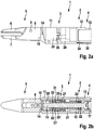
- FIGS. 2a and 2b is the distal portion of the medical instrument 1 as in Figs FIGS. 1a and 1b shown, however, the forceps jaw is in Fig. 2a and 2b closed.
- the closed position can be held between the jaws 6, 7, for example, a surgical needle (not shown).
- the tension sleeve 21 relative to the position with the jaw part 6 open (s. Fig. 1a, 1b ) in the proximal direction.
- the pull rod extending in or on the proximal section 4 of the shaft 2 has been pulled proximally, as a result of which the tension sleeve 21 has been displaced via the connecting lever 24, the intermediate piece 23 and the pivot bearing 22.
- the oblique surfaces 31, 31 ' now each such opposite to the inclined mating surfaces 32, 32' arranged that between these a larger gap is formed. Since the angle of inclination of the mating surfaces 32, 32 'is greater than that of the inclined surfaces 31, 31', the space in the in Fig. 2b shown axial longitudinal section on a wedge-shaped shape. The spaces are at the in Fig.
- FIG. 2b shown position of the tension sleeve 21 wide enough to each receive a locking element 25, 25 '.
- the locking slide 27 has been displaced in the distal direction. This can be effected by corresponding actuation of the push rod extending in or on the proximal section 4 of the shaft 2, which controls a corresponding axial displacement of the locking slide 27 via the connecting lever 30, the intermediate piece 29 and the pivot bearing 28.
- the locking slide 27 in turn displaces the locking elements 25, 25 'in the distal direction.
- the force to move the push rod distally and for moving the locking elements 25, 25 'in the interstices is characterized by a in a handle of the instrument (s. Fig. 4 ) applied control spring applied.
- the locking elements 25, 25 ' have a wedge shape at least in their distal region, wherein the wedge angle corresponds approximately to the opening angle of the intermediate space formed between the inclined surfaces 31, 31' and the respective mating surfaces 32, 32 '.
- the locking elements 25, 25 ' can be moved so far in the distal direction until they abut the respective oblique surface 31, 31' of the tension sleeve 21 and at the same time on the respective mating surface 32, 32 'of the guide sleeve 20; As a result, a distal stop for the movement of the locking elements 25, 25 'is achieved.
- the locking elements 25, 25 ' are so movably connected to the locking slide 27 that they can follow the oblique surfaces 31, 31' and the mating surfaces 32, 32 'to the two-sided concerns when inserted into the spaces. In this state, an axial displacement of the tension sleeve 21 in the distal direction is no longer possible because it is blocked by the locking elements 25, 25 '.
- the inclination angle of the inclined surfaces 31, 31 'and the mating surfaces 32, 32' are chosen such that a self-locking occurs, whereby a displacement of the tension sleeve 21 in the proximal direction is prevented.
- the oblique surfaces 31, 31 ' are inclined for this purpose by about 5 ° to 6 ° against the displacement direction of the tension sleeve 21, which is directed parallel to the longitudinal axis of the distal end portion 3 of the shaft 2, and the counter surfaces 32, 32' are about 10 ° inclined to 12 ° to the longitudinal axis.
- the movable jaw part 6 is thus locked in a self-locking manner, and a surgical needle held between the jaw parts 6, 7 is held firmly, without a user having to continue to exert a force for this purpose.
- the locking elements 25, 25 ', as well as the tension sleeve 21 and the guide sleeve 20, are made for example of stainless steel, wherein the locking elements 25, 25' and the surfaces 31, 31 'and the mating surfaces 32, 32' are preferably hardened.
- the jaws can be easily rotated by applying a torsional force on the rotatable shaft 15, 17. Also, the pivot bearings 22, 28 of the first and second transmission element are relieved and do not hinder the rotation. Furthermore, the distal end portion 3 of the shaft 2 can be pivoted freely relative to the proximal portion 4 of the shaft 2.
- the tension sleeve 21 is acted upon by the first transmission element again with tensile force.
- the clamping force is taken from the locking elements 25, 25 ', which can now be pulled out of the spaces controlled by the handle via the second transmission element.
- the tension sleeve 21 can move freely when the locking elements 25, 25 'are withdrawn, the jaw part 6 can be opened by means of the first transmission element, and the needle can be released from the jaw parts 6, 7.
- Fig. 3 are shown in the manner of an exploded view, the tension sleeve 21, the guide sleeve 20 and a locking element 25.
- the tension sleeve 21 is formed substantially cylindrical and has a continuous inner cavity 33 for receiving the distal end portion 15 of the rotatable shaft (s. Fig. 1b ).
- the tension sleeve 21 has a distal extension 34 which carries pins 35, 35 ', which engage in recesses of a fork-shaped extension of the pivotable jaw part 6 in order to pivot the jaw part 6 by axial displacement of the tension sleeve 21.
- On the outside of the tension sleeve 21 two flat inclined surfaces 31, 31 are arranged on opposite sides.
- the guide sleeve 20 is substantially formed as a cylindrical tube which carries on its inside two mutually opposite grooves 36, 36 ', in which the locking elements 25, 25' are guided.
- the respective bottom of the grooves 36, 36 ' forms the oblique mating surfaces 32, 32'. These are each flat surfaces in the illustrated embodiment.
- the tension sleeve 21 is received longitudinally displaceable within the guide sleeve 20, wherein the tension sleeve 21 is rotatably connected by the engagement of the extension 34 in the recess 37 of the guide sleeve 20 and at one of the distal portion 15 of the rotatable shaft and the pin 14 mediated rotation of the main part 8 is rotated by this.
- the oblique surfaces 31, 31 'on the outside of the tension sleeve 21 are arranged opposite the grooves 36, 36' and thus opposite the counter surfaces 32, 32 '.
- the locking element 25 is received with its distal part in the groove 36 and guided in this in the longitudinal direction.
- the distal part of the locking element 25 has a wedge-shaped shape, so that the locking element 25 can be easily inserted into the groove 36 until it makes surface contact with the surface 31 and the mating surface 32.
- Proximal note carries the locking element laterally two lugs 38, 38 ', with which it is attached to the locking slide 27 (s. Fig. 1b ).
- the locking element 25 can thus be displaced in the axial direction by means of the locking slide 27 and is pivotable about the axis formed by the lugs 38, 38 '.
- the locking element 25 is sufficiently movable in the radial direction to in between the Surface 31 and the counter surface 32 formed space to penetrate defined by abutment against the surface 31 and the counter surface 32 stop.
- the axially opposite the locking element 25 arranged second locking element 25 ' is designed in the same way and guided in the groove 36'.
- Fig. 4 the medical instrument according to the described embodiment is shown in an overall view.
- the distal end portion 3 of the shaft 2 can be pivoted relative to the proximal portion 4 of the shaft 2.
- a handle 40 is arranged, which has a handle with two handle parts 41, 41 ', which are connected to the proximal end of the tie rod 46 of the first transmission element.
- the pull rod 46 can be displaced proximally, thereby moving the movable jaw member 6 toward the stationary jaw member 7 to grip about a surgical needle.
- a slider 42 is arranged, which is connected to the push rod of the second transmission element. If the needle has been gripped firmly, the movable jaw part 6 can be unlocked by displacing the slider 42 in the distal direction.
- a catch 43 is provided between the handle parts 41, 41 '.
- the handle 40 has a rotary knob 44, with which the forceps jaw can be rotated about a longitudinal axis and which is for this purpose connected to the proximal portion 17 of the rotatable shaft, and a further rotary wheel 45, with which the pivoting movement of the distal end portion 3 of the shaft 2 can be controlled.
Abstract
Ein erfindungsgemäßes medizinisches Instrument weist einen langerstreckten Schaft (2) und ein an einem distalen Endabschnitt (3) des Schafts (2) angeordnetes Werkzeug (5) auf, das zwei insbesondere zum Halten eines Gegenstands miteinander zusammenwirkende Werkzeugelemente umfasst, von denen mindestens eines mittels eines längsverschiebbaren ersten Übertragungselements bewegbar ist. Dabei weist ein distaler Endabschnitt des ersten Übertragungselements eine zu einer Verschieberichtung geneigte Fläche (31, 31') auf, und der distale Endabschnitt (3) des Schafts (2) oder ein mit diesem verschiebefest verbundenes Element weist eine zur Verschieberichtung geneigte Gegenfläche (32, 32') auf, die mit der geneigten Fläche (31, 31') einen von einer Verschiebung des distalen Endabschnitts des ersten Übertragungselements abhängigen Zwischenraum bildet. Weiter ist mindestens ein Verriegelungselement (25, 25')ist, das zum Blockieren der Verschiebung des ersten Übertragungselements in den Zwischenraum hinein gerichtet und zum Lösen der Blockierung aus diesem heraus gerichtet bewegbar ist.A medical instrument according to the invention has an elongated shaft (2) and a tool (5) arranged on a distal end section (3) of the shaft (2), which comprises two tool elements cooperating with one another for holding an object, at least one of which by means of a longitudinally displaceable first transmission element is movable. In this case, a distal end section of the first transmission element has a surface (31, 31 ') inclined to a displacement direction, and the distal end section (3) of the shaft (2) or an element connected to the latter has a counter surface (32, 32 ') which forms with the inclined surface (31, 31') a dependent on a displacement of the distal end portion of the first transmission element gap. Further, at least one locking element (25, 25 ') is, which is directed to block the displacement of the first transmission element in the intermediate space and directed to release the blocking out of this movable.
Description
Die vorliegende Erfindung betrifft ein medizinisches Instrument, insbesondere ein chirurgisches Instrument, mit einem langerstreckten Schaft und einem an einem distalen Endabschnitt des Schafts angeordneten Werkzeug, das zwei insbesondere zum Halten eines Gegenstands miteinander zusammenwirkende Werkzeugelemente umfasst, von denen mindestens eines mittels eines längsverschiebbaren ersten Übertragungselements bewegbar ist.The present invention relates to a medical instrument, in particular a surgical instrument, having an elongate shaft and a tool arranged at a distal end portion of the shaft, comprising two tool elements cooperating with one another for holding an object, at least one of which is movable by means of a longitudinally displaceable first transmission element is.
Bei derartigen medizinischen Instrumenten stellt sich häufig die Aufgabe, dass ein Gegenstand mit dem Werkzeug gefasst und fest gehalten werden soll, um den Gegenstand mittels des chirurgischen Instruments bewegen und beispielsweise chirurgische Manipulationen mit dem Gegenstand ausführen zu können. So soll beispielsweise eine chirurgische Nadel gefasst und möglichst fest gehalten werden, um die Nadel in Gewebe einzustechen. Hierfür ist es wünschenswert, die miteinander zusammenwirkenden Werkzeugelemente in einer Halteposition, in der das chirurgische Element gegriffen ist, zu blockieren bzw. zu verriegeln, so dass ein Benutzer zum weiteren Halten des Gegenstands keine Kraft mehr aufwenden muss und diesen bequem bewegen kann. Eine derartige Verriegelung kann beispielsweise mittels einer an einer Handhabe angeordneten Raste erfolgen, mit der ein Handgriff, mit dem über eine Zugstange das mindestens eine bewegbare Werkzeugelement betätigt werden kann, in einer Halteposition verriegelt werden kann. Auf diese Weise kann zwar ein sicheres und festes Halten des Gegenstands ermöglicht werden, ohne dass hierfür eine fortgesetzte Kraftaufwendung durch den Benutzer erforderlich ist. Allerdings steht dabei die Zugstange unter Spannung, was im Hinblick auf die Handhabung und die Haltbarkeit des Instruments nachteilig ist. Ferner steht in dem Fall, dass das Werkzeug um eine Längsachse drehbar gelagert ist, im verriegelten Zustand das Drehlager des Werkzeugs unter Spannung und kann nur mit erheblichem Kraftaufwand rotiert werden. Die hohe Belastung bei Rotation kann auch zu einer Beschädigung des Instruments führen.In such medical instruments, the task often arises that an object should be grasped with the tool and held firmly in order to move the object by means of the surgical instrument and to be able to carry out, for example, surgical manipulations with the object. For example, a surgical needle should be grasped and held as tight as possible in order to pierce the needle into tissue. For this purpose, it is desirable to lock the interlocking tool elements in a holding position in which the surgical element is gripped, so that a user no longer needs to spend more power to hold the object further and can move it comfortably. Such a locking can be done for example by means of a handle arranged on a detent with which a handle with which a pull rod, the at least one movable tool element can be actuated, can be locked in a holding position. In this way, while a secure and firm hold of the object can be made possible without requiring a continuous application of force by the user is required. However, while the pull rod is under tension, which is disadvantageous in terms of handling and durability of the instrument. Furthermore, in the case that the tool is rotatably mounted about a longitudinal axis, in the locked state, the pivot bearing of the tool under tension and can only be rotated with considerable effort. The high load on rotation can also lead to damage to the instrument.
Aus
In
Gemäß
Bei den vorgenannten Lösungen erfolgt eine Verriegelung bzw. Feststellung der Maulteile in einer Halteposition, wobei der Riegelmechanismus im distalen Bereich des Instruments angeordnet ist. Es hat sich jedoch gezeigt, dass dabei nicht immer eine ausreichende Haltekraft zum Halten insbesondere einer chirurgischen Nadel erzielt werden kann und/oder zum Verriegeln bzw. Entriegeln ein relativ hoher Kraftaufwand notwendig ist.In the aforementioned solutions, a locking or determination of the jaw parts takes place in a holding position, wherein the locking mechanism is arranged in the distal region of the instrument. However, it has been found that not always a sufficient holding force for holding in particular a surgical needle can be achieved and / or for locking or unlocking a relatively high expenditure of force is necessary.
Es ist Aufgabe der vorliegenden Erfindung, ein medizinisches Instrument der genannten Art anzugeben, wobei die oben genannten Nachteile möglichst vermieden werden.It is an object of the present invention to provide a medical instrument of the type mentioned, wherein the above-mentioned disadvantages are avoided as possible.
Diese Aufgabe wird durch ein medizinisches Instrument gemäß Anspruch 1 gelöst.This object is achieved by a medical instrument according to
Vorteilhafte Weiterbildungen der Erfindung ergeben sich aus den Unteransprüchen.Advantageous developments of the invention will become apparent from the dependent claims.
Ein erfindungsgemäßes medizinisches Instrument ist insbesondere als chirurgisches, vorzugsweise als endoskopisches Instrument ausgebildet und weist einen lang erstreckten Schaft auf, der zum Einführen in einen körperinneren Hohlraum ausgebildet ist. Der Schaft ist vorzugsweise zumindest abschnittsweise starr, kann aber auch abschnittsweise flexibel sein. Am distalen (d.h. benutzerfernen) Endabschnitt des Schafts ist ein Werkzeug angeordnet, das insbesondere zur Durchführung chirurgischer Manipulationen bei einem endoskopischen Eingriff dient. Das Werkzeug ist vorzugsweise am distalen Ende des distalen Endabschnitts des Schafts angeordnet und ist vorzugsweise derart ausgebildet, dass es zumindest in einer geschlossenen Stellung an der Spitze des Schafts mit diesem durch eine Körperöffnung in den körperinneren Hohlraum eingeführt werden kann. Das Werkzeug umfasst zwei miteinander zusammenwirkende Werkzeugelemente, die insbesondere zum Greifen und Halten eines Gegenstands ausgebildet und gegeneinander bewegbar sind. Das medizinische Instrument kann beispielsweise als Nadelhalter ausgebildet sein, wobei die Werkzeugelemente zum Greifen und Halten einer chirurgischen Nadel angepasst sind.A medical instrument according to the invention is designed in particular as a surgical instrument, preferably as an endoscopic instrument, and has an elongated shaft which is designed for insertion into a body-internal cavity. The shank is preferably at least partially rigid, but may also be partially flexible. At the distal (i.e., away from the user) end portion of the shaft, a tool is arranged which is particularly useful for performing surgical manipulations in an endoscopic procedure. The tool is preferably located at the distal end of the distal end portion of the shaft and is preferably configured to be inserted into the body-internal cavity through the body opening, at least in a closed position at the tip of the shaft. The tool comprises two cooperating tool elements, which are designed in particular for gripping and holding an object and are movable relative to one another. The medical instrument can be designed, for example, as a needle holder, wherein the tool elements are adapted for gripping and holding a surgical needle.
Mindestens eines der beiden Werkzeugelemente, das im Folgenden als bewegliches Werkzeugelement bezeichnet wird, ist relativ zu dem distalen Endabschnitt des Schafts zum Zusammenwirken mit dem anderen Werkzeugelement beweglich angeordnet und mittels eines ersten Übertragungselements vom proximalen (d.h. benutzernahen) Ende des Schafts her bewegbar. Das erste Übertragungselement kann beispielsweise als Zugstange oder Schubstange ausgebildet sein und abschnittsweise innerhalb oder an einer Außenseite des Schafts verlaufen. Zum Bewegen des mindestens einen beweglichen Werkzeugelements ist das erste Übertragungselement im bzw. am Schaft längsverschiebbar gelagert. Um das mindestens eine bewegliche Werkzeugelement zu betätigen, kann am proximalen Ende des Schafts ein manuell betätigbarer Handgriff vorgesehen sein, der mit dem proximalen Ende des ersten Übertragungselements gekoppelt ist. Es kann aber auch eine motorische Betätigung des ersten Übertragungselements vorgesehen sein.At least one of the two tool members, hereinafter referred to as a movable tool member, is movably disposed relative to the distal end portion of the shaft for cooperation with the other tool member and by means of a first transmission member from the proximal (ie, near-user) end of the shaft movable. The first transmission element may be formed, for example, as a pull rod or push rod and extend in sections within or on an outer side of the shaft. For moving the at least one movable tool element, the first transmission element is mounted so as to be longitudinally displaceable in or on the shaft. In order to actuate the at least one movable tool element, a manually operable handle can be provided at the proximal end of the shaft, which is coupled to the proximal end of the first transmission element. But it can also be provided a motor actuation of the first transmission element.
Insbesondere kann das Werkzeug ein bewegliches und ein feststehendes Werkzeugelement umfassen, wobei das bewegliche Werkzeugelement zum Greifen und Halten des Gegenstands auf das feststehende zu bewegbar ist und zum Freigeben des Gegenstands von diesem wieder fort bewegbar ist. Das bewegliche Werkzeugelement kann schwenkbar an einem Hauptteil des Werkzeugs gelagert sein und beispielsweise als Maulteil ausgebildet sein, das gegenüber einem feststehenden, starr mit dem Hauptteil verbundenen Maulteil schwenkbar ist. Das Werkzeug kann aber auch beispielsweise zwei gegeneinander bewegliche Werkzeugelemente umfassen, etwa zwei schwenkbar am Hauptteil des Werkzeugs gelagerte Maulteile, die zum Greifen und Halten des Gegenstands aufeinander zu geschwenkt und zum Freigeben des Gegenstandes voneinander fort geschwenkt werden können. Sofern zwei schwenkbare Maulteile vorgesehen sind, können diese beispielsweise auf einer gemeinsamen Achse schwenkbar gelagert sein. Das erste Übertragungselement kann in an sich bekannter Weise mit dem schwenkbaren Maulteil bzw. mit den schwenkbaren Maulteilen gekoppelt sein, so dass durch eine Längsverschiebung des ersten Übertragungselements eine Schwenkbewegung des Maulteils bzw. der Maulteile bewirkt werden kann.In particular, the tool may comprise a movable and a stationary tool element, wherein the movable tool element for gripping and holding the object is to be moved to the fixed and movable to release the article from this again. The movable tool element may be pivotally mounted on a main part of the tool and be designed, for example, as a jaw part, which is pivotable relative to a stationary, rigidly connected to the main part jaw part. However, the tool may also include, for example, two mutually movable tool elements, such as two pivotally mounted on the main part of the tool jaw parts that can be pivoted toward each other for gripping and holding the object and pivoted to release the object from each other. If two pivotable jaw parts are provided, they can for example be mounted pivotably on a common axis. The first transmission element can be coupled in a manner known per se with the pivotable jaw part or with the pivotable jaw parts, so that a pivoting movement of the jaw part or the jaw parts can be effected by a longitudinal displacement of the first transmission element.
Erfindungsgemäß weist ein distaler Endabschnitt des ersten Übertragungselements eine zu einer Verschieberichtung des distalen Endabschnitts des ersten Übertragungselements geneigte Fläche auf. Die Verschieberichtung ist insbesondere parallel oder näherungsweise parallel zu einer Längsachse des distalen Endabschnitts des Schafts. Weiter weist der distale Endabschnitt des Schafts oder ein mit diesem verschiebefest verbundenes Element eine ebenfalls zur Verschieberichtung des distalen Endabschnitts des ersten Übertragungselements geneigte Gegenfläche auf. Die Gegenfläche kann beispielsweise an einem Außenrohr des distalen Endabschnitts des Schafts oder an einem Element des distalen Endabschnitts des Schafts angeordnet sein, das gegenüber dem Außenrohr axial nicht verschiebbar ist; das genannte Element kann beispielsweise fest mit dem Hauptteil des Werkzeugs verbunden sein. Die Fläche und die Gegenfläche, die im Folgenden auch als geneigte oder schräge Flächen bezeichnet werden, steigen insbesondere beide in proximaler oder beide in distaler Richtung an, wobei die Neigung bzw. Steigung der geneigten Flächen jeweils parallel zur Verschieberichtung betrachtet wird, beispielsweise entlang der Längsachse des distalen Endabschnitts des Schafts. Die Gegenfläche bildet mit der geneigten Fläche des distalen Endabschnitts des ersten Übertragungselements in Abhängigkeit von einer Verschiebeposition des distalen Endabschnitts des ersten Übertragungselements relativ zum distalen Endabschnitt des Schafts einen Zwischenraum aus. Insbesondere können die geneigte Fläche des distalen Endabschnitts des ersten Übertragungselements und die Gegenfläche zumindest in einer Verschiebeposition oder in einem Teilbereich eines Verschiebewegs des distalen Endabschnitts des ersten Übertragungselements einander gegenüberliegend angeordnet sein. Dabei können eine oder mehrere schräge Flächen und/oder Gegenflächen vorgesehen sein, die einander derart zugeordnet sein können, dass ein oder mehrere Zwischenräume gebildet werden.According to the invention, a distal end portion of the first transmission element has an inclined surface to a displacement direction of the distal end portion of the first transmission element. The displacement direction is in particular parallel or approximately parallel to a longitudinal axis of the distal end portion of the shaft. Furthermore, the distal end portion of the shaft or a member fixedly connected to the latter has a direction of displacement of the distal end portion of the first transmission element inclined counter surface on. The mating surface may, for example, be disposed on an outer tube of the distal end portion of the stem or on an element of the distal end portion of the stem which is axially non-displaceable with respect to the outer tube; said element may for example be firmly connected to the main part of the tool. The surface and the mating surface, which are also referred to below as inclined or inclined surfaces, increase in particular both in the proximal or both in the distal direction, wherein the inclination or slope of the inclined surfaces is viewed in each case parallel to the displacement direction, for example along the longitudinal axis the distal end portion of the shaft. The mating surface forms a gap with the inclined surface of the distal end portion of the first transmission member in response to a shift position of the distal end portion of the first transmission member relative to the distal end portion of the shaft. In particular, the inclined surface of the distal end portion of the first transmission element and the counter surface may be arranged opposite to each other at least in a sliding position or in a partial region of a displacement path of the distal end portion of the first transmission element. In this case, one or more inclined surfaces and / or mating surfaces can be provided, which can be associated with one another such that one or more intermediate spaces are formed.
Das erfindungsgemäße medizinische Instrument umfasst weiterhin mindestens ein Verriegelungselement, das derart in den Zwischenraum hinein bewegbar ist, dass eine Längsverschiebung des distalen Endabschnitts des ersten Übertragungselements relativ zum distalen Endabschnitt des Schafts blockiert und dadurch das mindestens eine bewegliche Werkzeugelement verriegelt werden kann. Zum Lösen der Blockierung bzw. zur Entriegelung ist das mindestens eine Verriegelungselement aus dem Zwischenraum wieder heraus bewegbar. Dabei muss das Verriegelungselement nicht vollständig in den Zwischenraum eingebracht und auch aus diesem nicht vollständig entfernt werden, sondern eine in den Zwischenraum hinein gerichtete Bewegung bzw. eine aus diesem heraus gerichtete Bewegung kann zum Blockieren bzw. zum Lösen der Blockierung ausreichen. Das mindestens eine Verriegelungselement ist insbesondere so weit in den Zwischenraum hinein bewegbar, dass es durch Kontakt mit der schrägen Fläche und der Gegenfläche eine Bewegung des ersten Übertragungselements relativ zum distalen Endabschnitt des Schafts zumindest in einer Bewegungsrichtung blockiert und dabei vorzugsweise durch Reibschluss in dem Zwischenraum gehalten wird. Entsprechend ist das mindestens eine Verriegelungselement so weit in umgekehrter Richtung bewegbar, dass der Reibschluss mit mindestens einer der den Zwischenraum bildenden schrägen Flächen aufgehoben wird und der distale Endabschnitt des ersten Übertragungselements relativ zum distalen Endabschnitt des Schafts wieder beweglich wird. Die entsprechende Bewegung des mindestens einen Verriegelungselements kann mittels eines zweiten Übertragungselements vom proximalen Ende des Schafts her steuerbar sein. Das zweite Übertragungselement kann insbesondere in einer Längsrichtung des Schafts verschiebbar sein und im Wesentlichen parallel zum ersten Übertragungselement geführt sein, etwa abschnittsweise an einer Außenseite des Schafts oder innerhalb des Schafts, und zumindest abschnittsweise als Zug- oder Schubstange ausgebildet sein. Es können mehrere Verriegelungselemente vorgesehen sein, die in der beschriebenen Weise in einen oder mehrere Zwischenräume hinein- und daraus heraus bewegbar sind.The medical instrument according to the invention further comprises at least one locking element which is movable into the space such that a longitudinal displacement of the distal end portion of the first transmission element relative to the distal end portion of the shaft blocked and thereby the at least one movable tool element can be locked. To release the blocking or unlocking the at least one locking element from the intermediate space is movable back out. In this case, the locking element does not have to be completely introduced into the intermediate space and also not completely removed therefrom, but a movement directed into the intermediate space or a movement directed out of this can be sufficient for blocking or for releasing the blockage. The at least one locking element is, in particular, movable into the intermediate space so far that, by contact with the inclined surface and the counter-surface, it moves the movement first transmission element is blocked relative to the distal end portion of the shaft at least in one direction of movement and is preferably held in the intermediate space by frictional engagement. Accordingly, the at least one locking element is movable so far in the reverse direction that the frictional engagement with at least one of the oblique surfaces forming the gap is canceled and the distal end portion of the first transmission element is movable again relative to the distal end portion of the shaft. The corresponding movement of the at least one locking element can be controllable by means of a second transmission element from the proximal end of the shaft. The second transmission element can in particular be displaceable in a longitudinal direction of the shaft and be guided substantially parallel to the first transmission element, approximately sectionally on an outer side of the shaft or within the shaft, and be formed at least in sections as a pull or push rod. There may be provided a plurality of locking elements, which in the manner described in one or more spaces in and out of it are movable.
Dadurch, dass der distale Endabschnitt des ersten Übertragungselements und der distale Endabschnitt des Schafts schräge Flächen aufweisen, die zumindest in einer Verschiebeposition des distalen Endabschnitts des ersten Übertragungselements einander gegenüberliegen, wird ein Zwischenraum gebildet, dessen Breite sich bei einer Längsverschiebung des ersten Übertragungselements relativ zum distalen Endabschnitt des Schafts verändert. Der Zwischenraum wird erfindungsgemäß genutzt, um durch Einbringen eines Verriegelungselements das erste Übertragungselement relativ zum distalen Endabschnitt des Schafts zu blockieren und damit das mindestens eine bewegliche Werkzeugelement in einer Halteposition zu arretieren, in der ein Gegenstand zwischen den Werkzeugelementen gehalten werden kann. Hierdurch kann auf einfache und sichere Weise eine Verriegelung des Werkzeugs ermöglicht werden, wodurch ein Gegenstand wie etwa eine chirurgische Nadel sicher zwischen den beiden Werkzeugelementen gehalten werden kann, ohne dass eine weitere Kraftausübung des Benutzers notwendig ist. Ferner kann hierdurch eine einfache und sichere Entriegelung zum Freigeben des gehaltenen Gegenstands ermöglicht werden, wobei zum Entriegeln vom Benutzer nur eine relativ geringe Kraft aufgebracht werden muss.Characterized in that the distal end portion of the first transmission element and the distal end portion of the shaft have inclined surfaces which face each other at least in a sliding position of the distal end portion of the first transmission element, a gap is formed whose width is at a longitudinal displacement of the first transmission element relative to the distal End portion of the shaft changed. The gap is used according to the invention to block by introducing a locking element, the first transmission element relative to the distal end portion of the shaft and thus to lock the at least one movable tool element in a holding position in which an object can be held between the tool elements. In this way, a locking of the tool can be made possible in a simple and secure manner, whereby an object such as a surgical needle can be securely held between the two tool elements, without further force application of the user is necessary. Furthermore, this can be a simple and secure release for releasing the held object are made possible, with only a relatively small force must be applied to unlock the user.
Gemäß einer bevorzugten Ausführungsform der Erfindung ist die schräge Fläche des distalen Endabschnitts des ersten Übertragungselements auf einer Außenseite des distalen Endabschnitts des ersten Übertragungselements angeordnet, und die Gegenfläche ist auf einer Innenseite eines rohrförmigen Elements angeordnet. Das rohrförmige Element kann beispielsweise ein Außenrohr des distalen Endabschnitts des Schafts sein, oder das rohrförmige Element kann das mit dem distalen Endabschnitt des Schafts verschiebefest verbundene Element sein. Insbesondere kann die Gegenfläche auf einer Innenseite eines rohr- oder hülsenförmigen Elements angeordnet sein, das drehbar, jedoch axial fixiert in das Außenrohr eingesetzt ist; das Element kann beispielsweise fest mit dem Hauptteil des Werkzeugs verbunden sein. Hierdurch wird eine einfach aufgebaute und besonders stabile und belastbare Anordnung geschaffen.According to a preferred embodiment of the invention, the inclined surface of the distal end portion of the first transmission member is disposed on an outer side of the distal end portion of the first transmission member, and the counter surface is disposed on an inner side of a tubular member. The tubular member may be, for example, an outer tube of the distal end portion of the stem, or the tubular member may be the element fixedly connected to the distal end portion of the stem. In particular, the mating surface may be disposed on an inner side of a tubular or sleeve-shaped element which is rotatably but axially fixed inserted into the outer tube; For example, the element may be fixedly connected to the main part of the tool. As a result, a simple structure and particularly stable and resilient arrangement is created.
Vorzugsweise ist das Werkzeug derart ausgebildet, dass durch eine Verschiebung des ersten Übertragungselements in der proximalen Richtung die beiden Werkzeugelemente zum Greifen eines Gegenstands geschlossen werden können und somit der Gegenstand durch eine innerhalb des ersten Übertragungselements wirkende Zugspannung gehalten werden kann. Die schräge Fläche und die Gegenfläche sind dabei beide in proximaler Richtung radial ansteigend ausgebildet, d.h. in einem axialen Schnitt gesehen beispielsweise mit in proximaler Richtung zunehmendem radialen Abstand von einer Längsachse des distalen Endabschnitts des ersten Übertragungselements. Bei dieser Ausführungsform kann das mindestens eine bewegliche Werkzeugelement zum festen Halten des Gegenstands durch Erzeugen einer Zugspannung im ersten Übertragungselement mit einer Haltekraft beaufschlagt werden, das bewegliche Werkzeugelement durch Bewegen des mindestens einen Verriegelungselements in dieser Halteposition verriegelt werden und die Haltekraft durch die Zugspannung zwischen dem distalen Endabschnitt des ersten Übertragungselements und dem beweglichen Werkzeugelement aufrecht erhalten werden. Dies ermöglicht die Ausübung einer besonders hohen Haltekraft und somit ein besonders festes und sicheres Halten des gegriffenen Gegenstands.Preferably, the tool is designed such that the two tool elements for gripping an object can be closed by a displacement of the first transmission element in the proximal direction and thus the article can be held by a tensile stress acting within the first transmission element. The oblique surface and the counter surface are both radially increasing in the proximal direction, i. seen in an axial section, for example, with increasing in the proximal direction radial distance from a longitudinal axis of the distal end portion of the first transmission element. In this embodiment, the at least one movable tool member for holding the object firmly by applying a tensile stress in the first transmission element can be acted upon with a holding force, the movable tool element are locked by moving the at least one locking element in this holding position and the holding force by the tension between the distal End portion of the first transmission element and the movable tool element are maintained. This allows the exercise of a particularly high holding force and thus a particularly firm and secure holding the gripped object.
Alternativ kann es beispielsweise vorgesehen sein, dass die Werkzeugelemente durch eine Verschiebung des ersten Übertragungselements in distaler Richtung geschlossen werden können, wobei beide schrägen Flächen in distaler Richtung radial ansteigend ausgebildet sind. Hierbei kann die Haltekraft durch eine Schubspannung zwischen dem beweglichen Werkzeugelement und dem distalen Endabschnitt des ersten Übertragungselements aufrecht erhalten werden.Alternatively, it can be provided, for example, that the tool elements are closed by a displacement of the first transmission element in the distal direction can, wherein both inclined surfaces are formed radially increasing in the distal direction. In this case, the holding force can be maintained by a shear stress between the movable tool element and the distal end portion of the first transmission element.
In besonders bevorzugter Weise bilden die beiden die Fläche und die Gegenfläche einen in einem axialen Schnitt gesehen keilförmigen Zwischenraum aus. In dem Fall, dass die Werkzeugelemente durch Verschiebung des ersten Übertragungselements in proximaler Richtung schließbar sind und die beiden schrägen Flächen in proximaler Richtung radial ansteigen, ist der keilförmige Zwischenraum vorzugsweise nach distal spitz zulaufend und nach proximal geöffnet. Dadurch, dass der Zwischenraum keilförmig ausgebildet ist, wird es ermöglicht, den distalen Endabschnitt des ersten Übertragungselements in einer Mehrzahl von Verschiebepositionen zu blockieren und damit das mindestens eine bewegliche Maulteil in einer Mehrzahl von Positionen zu verriegeln. Hierdurch wird ein Halten von unterschiedlich groß dimensionierten Gegenständen, beispielsweise von chirurgischen Nadeln mit unterschiedlichen Durchmessern, sowie ein Ausgleich von Toleranzen ermöglicht. Ferner kann auf diese Weise ein Hinein- und Herausbewegen des mindestens einen Verriegelungselements in den bzw. aus dem Zwischenraum mit nur einem geringen Kraftaufwand und damit ein besonders einfaches Ver- und Entriegeln ermöglicht werden.In a particularly preferred manner, the two form the surface and the counter surface seen in an axial section wedge-shaped gap. In the event that the tool elements can be closed by displacement of the first transmission element in the proximal direction and the two inclined surfaces increase radially in the proximal direction, the wedge-shaped intermediate space is preferably tapered towards the distal end and open proximally. Characterized in that the gap is wedge-shaped, it is possible to block the distal end portion of the first transmission element in a plurality of sliding positions and thus to lock the at least one movable jaw member in a plurality of positions. As a result, a holding of different sized objects, such as surgical needles with different diameters, as well as a compensation of tolerances is possible. Furthermore, in this way it is possible to move the at least one locking element in and out of the intermediate space with only little effort and thus a particularly simple locking and unlocking.
Vorzugsweise sind die schräge Fläche des distalen Endabschnitts des ersten Übertragungselements und die Gegenfläche mit solchen Neigungswinkeln zur Verschieberichtung geneigt, dass die Verschiebung des ersten Übertragungselements bei in den Zwischenraum eingeführtem Verriegelungselement selbsthemmend blockiert werden kann. Die schräge Fläche des distalen Endabschnitts des ersten Übertragungselements bildet beispielsweise einen Winkel im Bereich von beispielsweise etwa 5° bis 6° mit der Verschieberichtung des distalen Endabschnitts des ersten Übertragungselements, die zumindest näherungsweise parallel zur Längsachse des distalen Endabschnitts des Schafts verläuft, und die an dem distalen Endabschnitt des Schafts vorgesehene Gegenfläche bildet einen Winkel von beispielsweise etwa 10° bis 12° zur Verschieberichtung. Hierdurch wird eine selbsthemmende Blockierung der Bewegung des ersten Übertragungselements relativ zum distalen Endabschnitt des Schafts ermöglicht und insbesondere eine Verriegelung des mindestens einen beweglichen Werkzeugelements in beiden Richtungen, also sowohl gegen ein Öffnen als auch gegen ein weiteres Schließen der Werkzeugelemente.Preferably, the inclined surface of the distal end portion of the first transmission element and the counter surface are inclined at such inclination angles to the direction of displacement, that the displacement of the first transmission element can be self-locking blocked when inserted into the interspace locking element. For example, the sloped surface of the distal end portion of the first transmission member forms an angle in the range of, for example, about 5 ° to 6 ° with the direction of displacement of the distal end portion of the first transmission element that is at least approximately parallel to the longitudinal axis of the distal end portion of the stem distal end portion of the shaft provided counter surface forms an angle of, for example, about 10 ° to 12 ° to the direction of displacement. As a result, a self-locking blocking of the movement of the first transmission element relative to the distal end portion allows the shaft and in particular a locking of the at least one movable tool element in both directions, ie both against opening and against further closing of the tool elements.
In bevorzugter Weise ist das mindestens eine Verriegelungselement in einem axialen Schnitt gesehen näherungsweise keilförmig ausgebildet. Insbesondere ist das Verriegelungselement in dem Fall, dass die beiden schrägen Flächen in proximaler Richtung radial ansteigen, nach distal spitz zulaufend keilförmig ausgebildet. Hierdurch kann ebenfalls ein Halten von unterschiedlich großen Gegenständen und ein Ausgleich von Toleranzen sowie ein besonders leichtes Einführen und Herausziehen des Verriegelungselements in den bzw. aus dem Zwischenraum ermöglicht werden.Preferably, the at least one locking element seen in an axial section is formed approximately wedge-shaped. In particular, in the case in which the two inclined surfaces increase radially in the proximal direction, the locking element is wedge-shaped in a tapering manner towards the distal end. This can also be a holding of different sized objects and a compensation of tolerances and a particularly easy insertion and removal of the locking element in or out of the gap are made possible.
In besonders bevorzugter Weise sind sowohl der Zwischenraum als auch das Verriegelungselement in einem axialen Schnitt keilförmig ausgebildet, wobei die Keilwinkel des Verriegelungselements und des Zwischenraums im Wesentlichen gleich sind. Hierdurch kann eine größere Sicherheit bei der selbsthemmenden Blockierung erreichbar sein und zugleich eine Verriegelung in einem größeren Bereich der Längsverschiebung des ersten Übertragungselements und daher in einem größeren Bereich von Positionen des mindestens einen beweglichen Werkzeugelements bzw. Öffnungsweiten des Werkzeugs erreichbar sein. Hierdurch kann ein besonders sicheres Halten beispielsweise von Nadeln unterschiedlicher Durchmesser sowie ein verbesserter Ausgleich von Toleranzen ermöglicht werden.In a particularly preferred manner, both the gap and the locking element are wedge-shaped in an axial section, wherein the wedge angle of the locking element and the gap are substantially equal. In this way, a greater security in the self-locking blockage can be achieved and at the same time be achievable a locking in a larger region of the longitudinal displacement of the first transmission element and therefore in a larger range of positions of the at least one movable tool element or opening widths of the tool. This allows a particularly secure holding example of needles of different diameters and an improved compensation of tolerances are made possible.
Weiterhin ist es bevorzugt, dass das mindestens eine Verriegelungselement radial beweglich mit einem distalen Endabschnitt des zweiten Übertragungselements verbunden ist. Der distale Endabschnitt des zweiten Übertragungselements ist insbesondere als Verriegelungsschlitten ausgebildet, der parallel zur Verschieberichtung des distalen Endabschnitts des ersten Übertragungselements und damit zumindest näherungsweise parallel zur Längsachse des distalen Endabschnitts des Schafts verschiebbar ist. Das Verriegelungselement kann beispielsweise in radialer Richtung verschiebbar oder um eine Querachse schwenkbar mit dem Verriegelungsschlitten verbunden sein. Hierdurch wird eine einfache Anpassung des Verriegelungselements an unterschiedliche Verriegelungspositionen und damit auf einfache und sichere Weise eine Verriegelung des mindestens einen beweglichen Werkzeugelements in unterschiedlichen Stellungen ermöglicht.Furthermore, it is preferred that the at least one locking element is connected in a radially movable manner to a distal end section of the second transmission element. The distal end portion of the second transmission element is in particular designed as a locking slide, which is parallel to the displacement direction of the distal end portion of the first transmission element and thus at least approximately parallel to the longitudinal axis of the distal end portion of the shaft displaceable. The locking element may, for example, be displaceable in the radial direction or pivotally connected to the locking slide about a transverse axis. This will be a simple adaptation of the Locking element allows for different locking positions and thus in a simple and secure way locking the at least one movable tool element in different positions.
Vorzugsweise trägt das mindestens eine Verriegelungselement proximalseitig zwei einander gegenüberliegende, quer zur Längsrichtung des distalen Endabschnitts des Schafts bzw. quer zur Verschieberichtung des Verriegelungsschlittens gerichtete Nasen, mit denen es am Verriegelungsschlitten angehängt bzw. in entsprechende Ausnehmungen des Verriegelungsschlittens eingehängt ist. Hierdurch wird in besonders einfacher Weise eine radiale Beweglichkeit des mindestens einen Verriegelungselements zur Anpassung an unterschiedliche Verriegelungspositionen ermöglicht.Preferably, the at least one locking element carries on the proximal side two mutually opposite, transversely to the longitudinal direction of the distal end portion of the shaft or transversely to the direction of displacement of the locking slide directed lugs with which it is attached to the locking slide or hooked into corresponding recesses of the locking slide. As a result, a radial mobility of the at least one locking element for adaptation to different locking positions is made possible in a particularly simple manner.
In vorteilhafter Weise ist das mindestens eine Verriegelungselement im distalen Endabschnitt des Schafts in einer Nut geführt, deren Boden die Gegenfläche bildet. Insbesondere kann der distale Endabschnitt des Schafts rohrförmig ausgebildet sein, wobei an einer Innenseite des Rohrs oder an einer Innenseite eines in das Rohr eingesetzten rohr- oder hülsenförmigen Elements die Nut ausgebildet ist, die in der Verschieberichtung bzw. in Längsrichtung des distalen Endabschnitts des Schafts verläuft, deren Boden jedoch schräg zu dieser Richtung geneigt ist. Hierdurch wird auf besonders einfache und stabile Weise eine Verriegelung des mindestens einen beweglichen Werkzeugelements ermöglicht.Advantageously, the at least one locking element is guided in the distal end portion of the shaft in a groove whose bottom forms the counter surface. In particular, the distal end portion of the shaft may be tubular, wherein on an inner side of the tube or on an inner side of a tubular or sleeve-shaped element inserted into the tube, the groove is formed which extends in the displacement direction or in the longitudinal direction of the distal end portion of the shaft However, the bottom of which is inclined at an angle to this direction. As a result, a locking of the at least one movable tool element is made possible in a particularly simple and stable manner.
Vorzugsweise sind im distalen Endabschnitt des Schafts zwei Verriegelungselemente vorgesehen, die zur Verriegelung bzw. Entriegelung des mindestens einen beweglichen Werkzeugelements gemeinsam bewegbar sind, insbesondere mittels des zweiten Übertragungselements gemeinsam bewegbar sind, und in einen oder zwei entsprechende Zwischenräume hinein und daraus heraus bewegt werden können. Hierdurch wird auf einfache Weise eine besonders sichere Verriegelung ermöglicht.Preferably, two locking elements are provided in the distal end portion of the shaft, which are movable together for locking or unlocking of the at least one movable tool element, in particular by means of the second transmission element are jointly movable, and can be moved into one or two corresponding spaces in and out. As a result, a particularly secure locking is possible in a simple manner.
Die schräge Fläche und/oder die Gegenfläche können näherungsweise bzw. abschnittsweise eben oder konisch oder auch in einem axialen Schnitt ballig oder hohl ausgebildet sein. Gemäß einer bevorzugten Ausführungsform sind sowohl die schräge Fläche des distalen Endabschnitts des ersten Übertragungselements als auch die dieser zugeordnete Gegenfläche des distalen Endabschnitts des Schafts näherungsweise konisch ausgebildet, wobei die jeweilige Achse des Konus zumindest näherungsweise parallel zur Verschieberichtung des distalen Endabschnitts des ersten Übertragungselements bzw. zur Längsachse des distalen Endabschnitts des Schafts gerichtet ist. In diesem Fall können zwei Verriegelungselemente vorgesehen sein, die etwa symmetrisch auf bezüglich der Längsachse einander gegenüberliegenden Seiten angeordnet sein können.The oblique surface and / or the mating surface may be formed approximately or sectionally flat or conical or spherical or hollow in an axial section. According to a preferred embodiment, both the inclined surface of the distal end portion of the first transmission element and the mating surface associated therewith the distal end portion of the shaft is approximately conical, wherein the respective axis of the cone is at least approximately parallel to the displacement direction of the distal end portion of the first transmission element or to the longitudinal axis of the distal end portion of the shaft. In this case, two locking elements may be provided, which may be arranged approximately symmetrically with respect to the longitudinal axis of opposite sides.
Gemäß einer weiteren bevorzugten Ausführungsform der Erfindung weist der distale Endabschnitt des ersten Übertragungselements zwei einander axial gegenüberliegende, jeweils näherungsweise ebene schräge Flächen auf, und der distale Endabschnitt des Schafts weist zwei entsprechende, an einander gegenüberliegenden Seiten angeordnete näherungsweise ebene Gegenflächen auf. In diesem Fall sind zwei axial einander gegenüberliegend angeordnete Verriegelungselemente vorgesehen, die zum Verriegeln bzw. Entriegeln in die beiden, durch die jeweiligen einander gegenüber liegenden geneigten Flächen gebildeten Zwischenräume hinein bzw. aus diesen wieder herausbewegt werden können.According to a further preferred embodiment of the invention, the distal end portion of the first transmission element on two axially opposite, each approximately flat inclined surfaces, and the distal end portion of the shaft has two corresponding, arranged on opposite sides approximately flat mating surfaces. In this case, two locking elements arranged axially opposite one another are provided which can be moved in and out of the two spaces formed by the respective mutually opposite inclined surfaces for locking or unlocking.
Gemäß einer besonders bevorzugten Ausführungsform der Erfindung ist das Werkzeug relativ zum distalen Endabschnitt des Schafts um eine Drehachse drehbar, die mit der Längsachse des distalen Endabschnitts des Schafts zusammenfällt oder zu dieser parallel ist. Dabei kann das Werkzeug beispielsweise gegenüber einem Außenrohr des distalen Endabschnitts des Schafts drehbar sein. Weiter ist bei dieser Ausführungsform der distale Endabschnitt des ersten Übertragungselements ebenfalls um die Drehachse oder eine zu dieser parallele Achse relativ zu einem proximalen Abschnitt des ersten Übertragungselements drehbar ausgebildet. Der distale Endabschnitt des Schafts kann hierfür distalseitig ein entsprechendes Drehlager aufweisen, und der distale Endabschnitt des ersten Übertragungselements kann proximalseitig ein Drehlager aufweisen. Weiter kann ein distaler Endabschnitt des zweiten Übertragungselements als längsverschiebbarer Verriegelungsschlitten ausgebildet sein, der über ein relativ zum Verriegelungsschlitten um die Drehachse oder eine zu dieser parallele Achse drehbares Zwischenstück mit einem proximalen Abschnitt des zweiten Übertragungselements verbunden ist. Die Drehung des Werkzeugs zusammen mit dem distalen Endabschnitt des ersten Übertragungselements relativ zu den übrigen Abschnitten des Schafts bzw. des ersten Übertragungselements kann beispielsweise durch eine drehbare Welle gesteuert werden, die sich innerhalb des Schafts erstreckt und die drehfest mit einem Hauptteil des Werkzeugs verbunden ist. Dadurch, dass das Werkzeug um eine zur Längsachse des distalen Endabschnitts des Schafts parallele Drehachse drehbar ist, kann die Verwendbarkeit des medizinischen Instruments für eine Vielzahl von Situationen verbessert werden. Insbesondere kann es dadurch erreicht werden, dass die Werkzeugelemente sowie ein gegebenenfalls von diesen gehaltener Gegenstand in eine gewünschte Richtung orientiert werden können, ohne den proximalen Abschnitt des Schafts drehen zu müssen. Hierbei kann es dadurch, dass eine Verriegelung des mindestens einen beweglichen Werkzeugelements in einer Halteposition zum Halten des Gegenstands innerhalb des distalen Endabschnitts des Schafts erfolgt, ermöglicht werden, die Drehlager des Werkzeugs und des distalen Endabschnitts des ersten Übertragungselements von der Haltekraft zu entlasten. Hierdurch kann für einen Benutzer die Ausführung der Drehung erleichtert werden sowie ein übermäßiger Verschleiß des Instruments vermieden werden.According to a particularly preferred embodiment of the invention, the tool is rotatable relative to the distal end portion of the shaft about an axis of rotation coincident with or parallel to the longitudinal axis of the distal end portion of the shaft. In this case, the tool can be rotatable, for example, with respect to an outer tube of the distal end portion of the shaft. Further, in this embodiment, the distal end portion of the first transmission member is also formed to be rotatable about the rotation axis or an axis parallel thereto relative to a proximal portion of the first transmission member. The distal end section of the shaft can have a corresponding rotary bearing for this purpose on the distal side, and the distal end section of the first transmission element can have a rotary bearing on the proximal side. Further, a distal end portion of the second transmission element may be formed as a longitudinally displaceable locking slide, which is connected via a relative to the locking slide about the axis of rotation or an axis parallel to this axis rotatable intermediate piece with a proximal portion of the second transmission element. The rotation of the tool together with the distal end portion of the first transmission element relative to the remaining portions of the shaft or the first transmission element can be controlled for example by a rotatable shaft which extends within the shaft and which is non-rotatably connected to a main part of the tool. By virtue of the tool being rotatable about an axis of rotation parallel to the longitudinal axis of the distal end portion of the shaft, the usability of the medical instrument can be improved for a variety of situations. In particular, it can be achieved in that the tool elements and any object held by them can be oriented in a desired direction without having to rotate the proximal portion of the shaft. Here, by interlocking the at least one movable tool member in a holding position for holding the article within the distal end portion of the shaft, it is possible to relieve the rotational bearings of the tool and the distal end portion of the first transmission member of the holding force. This makes it easier for a user to perform the rotation and excessive wear of the instrument can be avoided.
Gemäß einer bevorzugten Ausführungsform der Erfindung ist der distale Endabschnitt des Schafts relativ zu einem proximalen Abschnitt des Schafts um eine quer zur Längsachse des Schafts gerichtete Querachse schwenkbar. Die Schwenkbewegung kann beispielsweise durch ein drittes Übertragungselement, das in oder am proximalen Abschnitt des Schafts verläuft, vom proximalen Ende des Schafts her gesteuert werden. In besonderes bevorzugter Weise ist sowohl der distale Endabschnitt des Schafts um die Querachse relativ zum proximalen Abschnitt des Schafts schwenkbar als auch das Werkzeug um eine parallel zur Längsachse des distalen Endabschnitts des Schafts gerichtete Drehachse drehbar. In diesem Fall kann es vorgesehen sein, dass die drehbare Welle, die zur Übertragung der Drehbewegung des Werkzeugs dient, im Bereich eines zum Abwinkeln des distalen Endabschnitts des Schafts dienenden Schwenkgelenks unterbrochen ist und die Übertragung einer Drehung beispielsweise mittels einer Verzahnung erfolgt, über die ein proximaler Abschnitt der Welle mit einem distalen Abschnitt zur Übertragung der Drehung zusammenwirkt. Weiter kann es vorgesehen sein, dass der distale Endabschnitt des ersten Übertragungselements über ein relativ zu diesem drehbar gelagertes Zwischenstück sowie im Bereich des Schwenkgelenks des distalen Endabschnitts des Schafts über einen Verbindungshebel mit einem proximalen Abschnitt des ersten Übertragungselements verbunden ist. In entsprechender Weise kann der distale Endabschnitt des zweiten Übertragungselements über ein drehbares Zwischenstück und im Bereich des Schwenkgelenks über einen Verbindungshebel mit einem proximalen Abschnitt des zweiten Übertragungselements verbunden sein. Die Verbindungshebel können insbesondere in einem radialen Außenbereich des Schafts angeordnet sein. Die drehbare Welle zur Steuerung der Drehbewegung des Werkzeugs verläuft vorzugsweise im Inneren des Schafts, insbesondere näherungsweise koaxial mit einer jeweiligen Längsachse sowohl des proximalen Abschnitts des Schafts als auch des distalen Endabschnitts. Das Schwenkgelenk zum Schwenken des distalen Endabschnitts des Schafts, einschließlich der drehbaren Welle und des ersten Übertragungselements im Bereich des Schwenkgelenks, kann wie in den nicht vorveröffentlichten Patentanmeldungen
Gemäß einer besonders bevorzugten Ausführungsform der Erfindung ist das mindestens eine Verriegelungselement in eine Verriegelungsposition durch Federkraft vorgespannt. Dies bedeutet beispielsweise in dem Fall, dass der Zwischenraum zwischen den einander zugeordneten schrägen Flächen in distaler Richtung keilförmig zuläuft, dass das Verriegelungselement in distaler Richtung federbelastet ist. Hierdurch kann es erreicht werden, dass das Verriegelungselement dann, wenn über das zweite Übertragungselement keine axiale Kraft ausgeübt wird, in die Verriegelungsposition gedrückt wird und somit das mindestens eine bewegliche Werkzeugelement verriegelt wird. Zum Entriegeln wird das mindestens eine Verriegelungselement mittels des zweiten Übertragungselements gegen die Federkraft bewegt, insbesondere aus dem keilförmig zulaufenden Zwischenraum so weit herausgezogen, dass der Kontakt mit mindestens einer der schrägen Flächen aufgehoben wird. Hierdurch kann die Sicherheit bei der Benutzung des medizinischen Instruments erhöht werden, da ein unbeabsichtigtes Freigeben der Bewegung des mindestens einen beweglichen Werkzeugelements mit größerer Sicherheit vermieden werden kann.According to a particularly preferred embodiment of the invention, the at least one locking element is biased in a locking position by spring force. This means, for example, in the case that the gap between the mutually associated inclined surfaces in the distal direction wedge-shaped, that the locking element is spring-loaded in the distal direction. In this way it can be achieved that, when no axial force is exerted on the second transmission element, the locking element is pressed into the locking position and thus the at least one movable tool element is locked. For unlocking the at least one locking element is moved by means of the second transmission element against the spring force, in particular pulled out so far from the wedge-shaped tapering gap that the contact with at least one of the inclined surfaces is canceled. This can increase the safety of using the medical instrument, since unintentional release of the movement of the at least one movable tool element can be avoided with greater certainty.
Vorzugsweise ist eine Steuerfeder, mit der das mindestens eine Verriegelungselement federbelastet ist, in einer Handhabe des medizinischen Instruments angeordnet. Hierdurch wird die Reinigung und Sterilisation des medizinischen Instruments erleichtert, da die Handhabe in der Regel nicht in direktem Kontakt mit Körperflüssigkeiten steht. Die von der Steuerfeder ausgeübte und über das zweite Übertragungselement übertragene Kraft ist relativ gering, so dass die Übertragung dieser Kraft über das zweite Übertragungselement nicht zu einer wesentlichen Belastung der Drehlager führt.Preferably, a control spring, with which the at least one locking element is spring-loaded, arranged in a handle of the medical instrument. This facilitates the cleaning and sterilization of the medical instrument, since the handle is generally not in direct contact with body fluids. The force exerted by the control spring and transmitted via the second transmission element is relatively small, so that the transmission of this force via the second transmission element does not lead to a significant load on the pivot bearing.
Es versteht sich, dass die vorstehend genannten und die nachstehend noch zu erläuternden Merkmale nicht nur in der jeweils angegebenen Kombination, sondern auch in anderen Kombinationen oder in Alleinstellung verwendbar sind, ohne den Rahmen der vorliegenden Erfindung zu verlassen.It is understood that the features mentioned above and those yet to be explained below can be used not only in the particular combination given, but also in other combinations or in isolation, without departing from the scope of the present invention.
Weitere Aspekte der Erfindung ergeben sich aus der nachfolgenden Beschreibung eines bevorzugten Ausführungsbeispiels und der beigefügten Zeichnung. Es zeigen:
-
Fig. 1a und 1b den distalen Endbereich eines medizinischen Instruments gemäß einem Ausführungsbeispiel der Erfindung mit geöffneten Maulteilen in einer teilweise transparenten Seitenansicht (Fig. 1a ) und einer axialen Schnittansicht (Fig. 1b ); -
Fig. 2a und 2b den distalen Endbereich des medizinischen Instruments gemäßFig. 1a und 1b in entsprechenden Ansichten, jedoch mit geschlossenen Maulteilen; -
Fig. 3 eine Zughülse, eine Führungshülse und ein Verriegelungselement des medizinischen Instruments gemäßFig. 1a und 1b ; -
Fig. 4 das medizinische Instrument gemäßFig. 1a und 1b in einer Gesamtansicht.
-
Fig. 1a and 1b the distal end region of a medical instrument according to an exemplary embodiment of the invention with open jaws in a partially transparent side view (FIG.Fig. 1a ) and an axial sectional view (Fig. 1b ); -
Fig. 2a and 2b the distal end portion of the medical instrument according toFig. 1a and 1b in corresponding views, but with closed jaw parts; -
Fig. 3 a tension sleeve, a guide sleeve and a locking element of the medical instrument according toFig. 1a and 1b ; -
Fig. 4 the medical instrument according toFig. 1a and 1b in an overall view.
In
Innerhalb des Außenrohrs 11 des distalen Endabschnitts 3 des Schafts 2 ist eine Führungshülse 20 angeordnet, die fest mit dem Hauptteil 8 verbunden ist und deren Funktion unten näher beschrieben wird. Innerhalb der Führungshülse 20 ist in Längsrichtung verschiebbar, jedoch gegenüber dem Hauptteil 8 und gegenüber der Führungshülse 20 drehfest, eine Zughülse 21 gelagert, die den distalen Endabschnitt 15 der drehbaren Welle aufnimmt und auf diesem gleitet. Die Zughülse 21 ist distalseitig so mit dem schwenkbaren Maulteil 6 gekoppelt, dass eine axiale Verschiebung der Zughülse 21 in distaler Richtung ein Öffnen des Maulteils 6 und eine axiale Verschiebung in proximaler Richtung ein Schließen des Maulteils 6 bewirkt. Proximalseitig ist die Zughülse 21 über ein Drehlager 22 mit einem ebenfalls axial verschiebbaren Zwischenstück 23 verbunden, das wiederum über einen Verbindungshebel 24 mit einer am bzw. im proximalen Abschnitt 4 des Schafts 2 verlaufenden Zugstange verbunden ist (s.
In der Führungshülse 20 sind zwei symmetrisch zur Längsachse angeordnete Verriegelungselemente 25, 25' längs verschiebbar geführt. Die Verriegelungselemente 25, 25' sind mit einem ringförmigen, längsverschiebbar auf der Zughülse 21 gelagerten Verriegelungsschlitten 27 verbunden. Der Verriegelungsschlitten 27 ist über ein Drehlager 28 drehbar mit einem Zwischenstück 29 verbunden, das über einen Verbindungshebel 30 mit einer Schubstange, die am bzw. im proximalen Abschnitt 4 des Schafts 2 verläuft, verbunden ist (s.
Wie in
In den
Die Verriegelungselemente 25, 25' weisen zumindest in ihrem distalen Bereich eine Keilform auf, wobei der Keilwinkel etwa dem Öffnungswinkel des zwischen den schrägen Flächen 31, 31' und den jeweiligen Gegenflächen 32, 32' gebildeten Zwischenraums entspricht. Wie in
Zum Halten einer chirurgischen Nadel wird diese zunächst durch Schließen des Maulteils 6 gegriffen. Dabei befinden sich die Verriegelungselemente 25, 25' außerhalb der Zwischenräume zwischen den Flächen 31, 31' der Zughülse 21 und den Gegenflächen 32, 32' der Führungshülse 20. Das erste Übertragungselement wird zum Schließen des Zangenmauls in proximaler Richtung gezogen, während das zweite Übertragungselement in seiner proximalen Endposition verbleibt (s.
Da das Drehlager 10 des Werkzeugs entlastet ist, können die Maulteile durch Aufbringung einer Torsionskraft über die drehbare Welle 15, 17 leicht rotiert werden. Auch die Drehlager 22, 28 des ersten bzw. zweiten Übertragungselements sind entlastet und behindern die Drehung nicht. Ferner kann der distale Endabschnitt 3 des Schafts 2 ungehindert gegenüber dem proximalen Abschnitt 4 des Schafts 2 geschwenkt werden.Since the pivot bearing 10 of the tool is relieved, the jaws can be easily rotated by applying a torsional force on the
Zum Lösen der Verriegelung wird die Zughülse 21 über das erste Übertragungselement wieder mit Zugkraft beaufschlagt. Damit wird die Klemmkraft von den Verriegelungselementen 25, 25' genommen, die nun von der Handhabe aus gesteuert über das zweite Übertragungselement aus den Zwischenräumen herausgezogen werden können. Die Zughülse 21 kann sich bei zurückgezogenen Verriegelungselementen 25, 25' wieder frei bewegen, das Maulteil 6 kann mittels des ersten Übertragungselements geöffnet werden, und die Nadel kann aus den Maulteilen 6, 7 gelöst werden.To release the lock, the
In
Die Führungshülse 20 ist im Wesentlichen als zylindrisches Rohr ausgebildet, das auf seiner Innenseite zwei einander gegenüberliegende Nuten 36, 36' trägt, in denen die Verriegelungselemente 25, 25' geführt sind. Der jeweilige Boden der Nuten 36, 36' bildet die schrägen Gegenflächen 32, 32'. Diese sind im dargestellten Ausführungsbeispiel jeweils ebene Flächen. In dem medizinischen Instrument 1 ist die Zughülse 21 innerhalb der Führungshülse 20 längsverschiebbar aufgenommen, wobei die Zughülse 21 durch den Eingriff des Fortsatzes 34 in die Ausnehmung 37 der Führungshülse 20 mit dieser drehfest verbunden ist und bei einer über den distalen Abschnitt 15 der drehbaren Welle und den Stift 14 vermittelten Drehung des Hauptteils 8 von diesem mitgedreht wird. Die schrägen Flächen 31, 31' auf der Außenseite der Zughülse 21 sind gegenüber den Nuten 36, 36' und damit gegenüber den Gegenflächen 32, 32' angeordnet.The
Das Verriegelungselement 25 ist mit seinem distalen Teil in der Nut 36 aufgenommen und in dieser in Längsrichtung geführt. Der distale Teil des Verriegelungselements 25 hat eine keilförmige Gestalt, so dass das Verriegelungselement 25 leicht bis zur flächigen Berührung mit der Fläche 31 und der Gegenfläche 32 in die Nut 36 eingeführt werden kann. Proximalseitig trägt das Verriegelungselement seitlich zwei Nasen 38, 38', mit denen es am Verriegelungsschlitten 27 angehängt ist (s.
In
Der Übersichtlichkeit halber sind nicht in allen Figuren alle Bezugszeichen dargestellt. Zu einer Figur nicht erläuterte Bezugszeichen haben die gleiche Bedeutung wie in den übrigen Figuren.For clarity, not all figures are shown in all figures. Reference numerals not explained to a figure have the same meaning as in the other figures.
- 11
- Instrumentinstrument
- 22
- Schaftshaft
- 33
- Distaler EndabschnittDistal end section
- 44
- Proximaler AbschnittProximal section
- 55
- WerkzeugTool
- 66
- Maulteiljaw
- 77
- Maulteiljaw
- 88th
- HauptteilBulk
- 99
- Schwenkachseswivel axis
- 1010
- Drehlagerpivot bearing
- 1111
- Außenrohrouter tube
- 1212
- Gelenkteiljoint part
- 1313
- Außenrohrouter tube
- 1414
- Stiftpen
- 1515
- Distaler EndabschnittDistal end section
- 1616
- Verzahnunggearing
- 1717
- Proximaler AbschnittProximal section
- 2020
- Führungshülseguide sleeve
- 2121
- Zughülsepulling sleeve
- 2222
- Drehlagerpivot bearing
- 2323
- Zwischenstückconnecting piece
- 2424
- Verbindungshebelconnecting lever
- 25, 25'25, 25 '
- Verriegelungselementlocking element
- 2727
- Verriegelungsschlittenlocking slide
- 2828
- Drehlagerpivot bearing
- 2929
- Zwischenstückconnecting piece
- 3030
- Verbindungshebelconnecting lever
- 31, 3131, 31
- 'Fläche'Area
- 32,32
- 32'Gegenfläche32'Gegenfläche
- 3333
- Hohlraumcavity
- 3434
- Fortsatzextension
- 35, 35'35, 35 '
- Stiftpen
- 36, 36'36, 36 '
- Nutgroove
- 3737
- Ausnehmungrecess
- 38, 38'38, 38 '
- Nasenose
- 4040
- Handhabehandle
- 41, 41'41, 41 '
- Griffteilhandle part
- 4242
- Schieberpusher
- 4343
- Rastenotch
- 4444
- Drehradrotating wheel
- 4545
- Drehradrotating wheel
- 4646
- Zugstangepull bar
Claims (14)
Applications Claiming Priority (1)
| Application Number | Priority Date | Filing Date | Title |
|---|---|---|---|
| DE102016103640.4A DE102016103640A1 (en) | 2016-03-01 | 2016-03-01 | Medical instrument |
Publications (2)
| Publication Number | Publication Date |
|---|---|
| EP3213700A1 true EP3213700A1 (en) | 2017-09-06 |
| EP3213700B1 EP3213700B1 (en) | 2018-10-24 |
Family
ID=58098428
Family Applications (1)
| Application Number | Title | Priority Date | Filing Date |
|---|---|---|---|
| EP17155947.9A Active EP3213700B1 (en) | 2016-03-01 | 2017-02-14 | Medical instrument |
Country Status (3)
| Country | Link |
|---|---|
| US (1) | US10342560B2 (en) |
| EP (1) | EP3213700B1 (en) |
| DE (1) | DE102016103640A1 (en) |
Families Citing this family (3)
| Publication number | Priority date | Publication date | Assignee | Title |
|---|---|---|---|---|
| EP2792319B1 (en) * | 2013-04-17 | 2020-10-21 | JakuTec Medizintechnik GmbH & Co. KG | Actuating element and rocker pair for an actuating element |
| DE102016103640A1 (en) * | 2016-03-01 | 2017-09-07 | Karl Storz Gmbh & Co. Kg | Medical instrument |
| DE102020119462A1 (en) | 2020-07-23 | 2022-01-27 | Karl Storz Se & Co. Kg | MEDICAL INSTRUMENT |
Citations (4)
| Publication number | Priority date | Publication date | Assignee | Title |
|---|---|---|---|---|
| US5626607A (en) * | 1995-04-03 | 1997-05-06 | Heartport, Inc. | Clamp assembly and method of use |
| US7896900B2 (en) | 2006-06-29 | 2011-03-01 | University Of Dundee | Medical instrument for grasping an object, in particular needle holder |
| DE102009055747A1 (en) | 2009-11-26 | 2011-06-09 | Olympus Winter & Ibe Gmbh | Surgical forceps with grooving |
| EP2522280A1 (en) | 2011-05-11 | 2012-11-14 | University Of Dundee | Medical instrument for grasping an object, in particular a needle holder |
Family Cites Families (4)
| Publication number | Priority date | Publication date | Assignee | Title |
|---|---|---|---|---|
| DE102011081464A1 (en) * | 2011-08-24 | 2013-02-28 | Karl Storz Gmbh & Co. Kg | Tool for a micro-invasive-surgical instrument |
| DE102015015655A1 (en) | 2015-12-01 | 2017-06-01 | Karl Storz Gmbh & Co. Kg | Medical instrument |
| DE102015015664A1 (en) | 2015-12-01 | 2017-06-14 | Karl Storz Gmbh & Co. Kg | Medical instrument |
| DE102016103640A1 (en) * | 2016-03-01 | 2017-09-07 | Karl Storz Gmbh & Co. Kg | Medical instrument |
-
2016
- 2016-03-01 DE DE102016103640.4A patent/DE102016103640A1/en not_active Withdrawn
-
2017
- 2017-02-14 EP EP17155947.9A patent/EP3213700B1/en active Active
- 2017-02-24 US US15/441,384 patent/US10342560B2/en active Active
Patent Citations (4)
| Publication number | Priority date | Publication date | Assignee | Title |
|---|---|---|---|---|
| US5626607A (en) * | 1995-04-03 | 1997-05-06 | Heartport, Inc. | Clamp assembly and method of use |
| US7896900B2 (en) | 2006-06-29 | 2011-03-01 | University Of Dundee | Medical instrument for grasping an object, in particular needle holder |
| DE102009055747A1 (en) | 2009-11-26 | 2011-06-09 | Olympus Winter & Ibe Gmbh | Surgical forceps with grooving |
| EP2522280A1 (en) | 2011-05-11 | 2012-11-14 | University Of Dundee | Medical instrument for grasping an object, in particular a needle holder |
Also Published As
| Publication number | Publication date |
|---|---|
| DE102016103640A1 (en) | 2017-09-07 |
| EP3213700B1 (en) | 2018-10-24 |
| US20170252053A1 (en) | 2017-09-07 |
| US10342560B2 (en) | 2019-07-09 |
Similar Documents
| Publication | Publication Date | Title |
|---|---|---|
| EP2510888B1 (en) | Handling device for a micro-invasive surgical instrument | |
| EP1014879B1 (en) | Medical screwdriver | |
| EP0645127B1 (en) | Hip prostheses extractor with sliding mass | |
| DE19707373C1 (en) | Releasable connection of two tube shaft instruments or instrument parts | |
| EP1082061A1 (en) | Handle for a medical hollow shaft instrument | |
| EP2510889B1 (en) | Handling device for a micro-invasive surgical instrument | |
| EP3213700B1 (en) | Medical instrument | |
| EP3410965B1 (en) | Instrument for guiding a rod into an implant holder | |
| EP1905369B1 (en) | Screwdriver for handling a screw in a human or animal body | |
| EP2904978A1 (en) | Retractor and operating method | |
| EP3351192A2 (en) | Surgical instrument, in particular for neurosurgery | |
| WO2011063892A1 (en) | Surgical forceps having engagement in a groove | |
| DE102006016214A1 (en) | Surgical instrument grip-handle e.g. for endoscope, uses resetting member for holding actuating element in idling position under pre-tension | |
| EP2785262B1 (en) | Surgical handgrip and surgical tubular shaft instrument with a surgical handgrip | |
| EP1365691B1 (en) | Medical instrument | |
| DE202011052176U1 (en) | Surgical handle and surgical tubular shaft instrument with a surgical handle | |
| DE202009003255U1 (en) | Trocar guide sleeve and trocar system | |
| DE202007000427U1 (en) | Surgical operating handle for a surgical instrument, especially an endoscopic instrument, comprises a handle part positioned on the operating handle | |
| EP4054447B1 (en) | Medical sliding shaft instrument | |
| DE202006005632U1 (en) | Endoscopic surgical instrument, comprising additional return element for smoother action | |
| EP3943024B1 (en) | Medical instrument | |
| EP2702950A1 (en) | Medical tool system and handle and tool for a medical tool system | |
| DE102016101822A1 (en) | Instrument for guiding a rod into an implant receptacle | |
| EP1941840B1 (en) | Surgical instrument | |
| WO2023011976A1 (en) | Medical instrument |
Legal Events
| Date | Code | Title | Description |
|---|---|---|---|
| PUAI | Public reference made under article 153(3) epc to a published international application that has entered the european phase |
Free format text: ORIGINAL CODE: 0009012 |
|
| STAA | Information on the status of an ep patent application or granted ep patent |
Free format text: STATUS: THE APPLICATION HAS BEEN PUBLISHED |
|
| AK | Designated contracting states |
Kind code of ref document: A1 Designated state(s): AL AT BE BG CH CY CZ DE DK EE ES FI FR GB GR HR HU IE IS IT LI LT LU LV MC MK MT NL NO PL PT RO RS SE SI SK SM TR |
|
| AX | Request for extension of the european patent |
Extension state: BA ME |
|
| RAP1 | Party data changed (applicant data changed or rights of an application transferred) |
Owner name: KARL STORZ SE & CO. KG |
|
| STAA | Information on the status of an ep patent application or granted ep patent |
Free format text: STATUS: REQUEST FOR EXAMINATION WAS MADE |
|
| 17P | Request for examination filed |
Effective date: 20180301 |
|
| RBV | Designated contracting states (corrected) |
Designated state(s): AL AT BE BG CH CY CZ DE DK EE ES FI FR GB GR HR HU IE IS IT LI LT LU LV MC MK MT NL NO PL PT RO RS SE SI SK SM TR |
|
| GRAP | Despatch of communication of intention to grant a patent |
Free format text: ORIGINAL CODE: EPIDOSNIGR1 |
|
| STAA | Information on the status of an ep patent application or granted ep patent |
Free format text: STATUS: GRANT OF PATENT IS INTENDED |
|
| INTG | Intention to grant announced |
Effective date: 20180718 |
|
| GRAS | Grant fee paid |
Free format text: ORIGINAL CODE: EPIDOSNIGR3 |
|
| GRAA | (expected) grant |
Free format text: ORIGINAL CODE: 0009210 |
|
| STAA | Information on the status of an ep patent application or granted ep patent |
Free format text: STATUS: THE PATENT HAS BEEN GRANTED |
|
| AK | Designated contracting states |
Kind code of ref document: B1 Designated state(s): AL AT BE BG CH CY CZ DE DK EE ES FI FR GB GR HR HU IE IS IT LI LT LU LV MC MK MT NL NO PL PT RO RS SE SI SK SM TR |
|
| REG | Reference to a national code |
Ref country code: CH Ref legal event code: EP |
|
| REG | Reference to a national code |
Ref country code: IE Ref legal event code: FG4D Free format text: LANGUAGE OF EP DOCUMENT: GERMAN |
|
| REG | Reference to a national code |
Ref country code: AT Ref legal event code: REF Ref document number: 1055750 Country of ref document: AT Kind code of ref document: T Effective date: 20181115 |
|
| REG | Reference to a national code |
Ref country code: DE Ref legal event code: R096 Ref document number: 502017000275 Country of ref document: DE |
|
| REG | Reference to a national code |
Ref country code: NL Ref legal event code: MP Effective date: 20181024 |
|
| REG | Reference to a national code |
Ref country code: LT Ref legal event code: MG4D |
|
| PG25 | Lapsed in a contracting state [announced via postgrant information from national office to epo] |
Ref country code: NL Free format text: LAPSE BECAUSE OF FAILURE TO SUBMIT A TRANSLATION OF THE DESCRIPTION OR TO PAY THE FEE WITHIN THE PRESCRIBED TIME-LIMIT Effective date: 20181024 |
|
| PG25 | Lapsed in a contracting state [announced via postgrant information from national office to epo] |
Ref country code: LV Free format text: LAPSE BECAUSE OF FAILURE TO SUBMIT A TRANSLATION OF THE DESCRIPTION OR TO PAY THE FEE WITHIN THE PRESCRIBED TIME-LIMIT Effective date: 20181024 Ref country code: HR Free format text: LAPSE BECAUSE OF FAILURE TO SUBMIT A TRANSLATION OF THE DESCRIPTION OR TO PAY THE FEE WITHIN THE PRESCRIBED TIME-LIMIT Effective date: 20181024 Ref country code: BG Free format text: LAPSE BECAUSE OF FAILURE TO SUBMIT A TRANSLATION OF THE DESCRIPTION OR TO PAY THE FEE WITHIN THE PRESCRIBED TIME-LIMIT Effective date: 20190124 Ref country code: NO Free format text: LAPSE BECAUSE OF FAILURE TO SUBMIT A TRANSLATION OF THE DESCRIPTION OR TO PAY THE FEE WITHIN THE PRESCRIBED TIME-LIMIT Effective date: 20190124 Ref country code: PL Free format text: LAPSE BECAUSE OF FAILURE TO SUBMIT A TRANSLATION OF THE DESCRIPTION OR TO PAY THE FEE WITHIN THE PRESCRIBED TIME-LIMIT Effective date: 20181024 Ref country code: ES Free format text: LAPSE BECAUSE OF FAILURE TO SUBMIT A TRANSLATION OF THE DESCRIPTION OR TO PAY THE FEE WITHIN THE PRESCRIBED TIME-LIMIT Effective date: 20181024 Ref country code: LT Free format text: LAPSE BECAUSE OF FAILURE TO SUBMIT A TRANSLATION OF THE DESCRIPTION OR TO PAY THE FEE WITHIN THE PRESCRIBED TIME-LIMIT Effective date: 20181024 Ref country code: IS Free format text: LAPSE BECAUSE OF FAILURE TO SUBMIT A TRANSLATION OF THE DESCRIPTION OR TO PAY THE FEE WITHIN THE PRESCRIBED TIME-LIMIT Effective date: 20190224 Ref country code: FI Free format text: LAPSE BECAUSE OF FAILURE TO SUBMIT A TRANSLATION OF THE DESCRIPTION OR TO PAY THE FEE WITHIN THE PRESCRIBED TIME-LIMIT Effective date: 20181024 |
|
| PG25 | Lapsed in a contracting state [announced via postgrant information from national office to epo] |
Ref country code: GR Free format text: LAPSE BECAUSE OF FAILURE TO SUBMIT A TRANSLATION OF THE DESCRIPTION OR TO PAY THE FEE WITHIN THE PRESCRIBED TIME-LIMIT Effective date: 20190125 Ref country code: SE Free format text: LAPSE BECAUSE OF FAILURE TO SUBMIT A TRANSLATION OF THE DESCRIPTION OR TO PAY THE FEE WITHIN THE PRESCRIBED TIME-LIMIT Effective date: 20181024 Ref country code: RS Free format text: LAPSE BECAUSE OF FAILURE TO SUBMIT A TRANSLATION OF THE DESCRIPTION OR TO PAY THE FEE WITHIN THE PRESCRIBED TIME-LIMIT Effective date: 20181024 Ref country code: PT Free format text: LAPSE BECAUSE OF FAILURE TO SUBMIT A TRANSLATION OF THE DESCRIPTION OR TO PAY THE FEE WITHIN THE PRESCRIBED TIME-LIMIT Effective date: 20190224 Ref country code: AL Free format text: LAPSE BECAUSE OF FAILURE TO SUBMIT A TRANSLATION OF THE DESCRIPTION OR TO PAY THE FEE WITHIN THE PRESCRIBED TIME-LIMIT Effective date: 20181024 |
|
| REG | Reference to a national code |
Ref country code: DE Ref legal event code: R097 Ref document number: 502017000275 Country of ref document: DE |
|
| PG25 | Lapsed in a contracting state [announced via postgrant information from national office to epo] |
Ref country code: DK Free format text: LAPSE BECAUSE OF FAILURE TO SUBMIT A TRANSLATION OF THE DESCRIPTION OR TO PAY THE FEE WITHIN THE PRESCRIBED TIME-LIMIT Effective date: 20181024 Ref country code: CZ Free format text: LAPSE BECAUSE OF FAILURE TO SUBMIT A TRANSLATION OF THE DESCRIPTION OR TO PAY THE FEE WITHIN THE PRESCRIBED TIME-LIMIT Effective date: 20181024 |
|
| PG25 | Lapsed in a contracting state [announced via postgrant information from national office to epo] |
Ref country code: RO Free format text: LAPSE BECAUSE OF FAILURE TO SUBMIT A TRANSLATION OF THE DESCRIPTION OR TO PAY THE FEE WITHIN THE PRESCRIBED TIME-LIMIT Effective date: 20181024 Ref country code: SK Free format text: LAPSE BECAUSE OF FAILURE TO SUBMIT A TRANSLATION OF THE DESCRIPTION OR TO PAY THE FEE WITHIN THE PRESCRIBED TIME-LIMIT Effective date: 20181024 Ref country code: EE Free format text: LAPSE BECAUSE OF FAILURE TO SUBMIT A TRANSLATION OF THE DESCRIPTION OR TO PAY THE FEE WITHIN THE PRESCRIBED TIME-LIMIT Effective date: 20181024 Ref country code: SM Free format text: LAPSE BECAUSE OF FAILURE TO SUBMIT A TRANSLATION OF THE DESCRIPTION OR TO PAY THE FEE WITHIN THE PRESCRIBED TIME-LIMIT Effective date: 20181024 |
|
| PLBE | No opposition filed within time limit |
Free format text: ORIGINAL CODE: 0009261 |
|
| STAA | Information on the status of an ep patent application or granted ep patent |
Free format text: STATUS: NO OPPOSITION FILED WITHIN TIME LIMIT |
|
| 26N | No opposition filed |
Effective date: 20190725 |
|
| PG25 | Lapsed in a contracting state [announced via postgrant information from national office to epo] |
Ref country code: SI Free format text: LAPSE BECAUSE OF FAILURE TO SUBMIT A TRANSLATION OF THE DESCRIPTION OR TO PAY THE FEE WITHIN THE PRESCRIBED TIME-LIMIT Effective date: 20181024 Ref country code: LU Free format text: LAPSE BECAUSE OF NON-PAYMENT OF DUE FEES Effective date: 20190214 Ref country code: MC Free format text: LAPSE BECAUSE OF FAILURE TO SUBMIT A TRANSLATION OF THE DESCRIPTION OR TO PAY THE FEE WITHIN THE PRESCRIBED TIME-LIMIT Effective date: 20181024 |
|
| REG | Reference to a national code |
Ref country code: BE Ref legal event code: MM Effective date: 20190228 |
|
| REG | Reference to a national code |
Ref country code: IE Ref legal event code: MM4A |
|
| PG25 | Lapsed in a contracting state [announced via postgrant information from national office to epo] |
Ref country code: IE Free format text: LAPSE BECAUSE OF NON-PAYMENT OF DUE FEES Effective date: 20190214 |
|
| PG25 | Lapsed in a contracting state [announced via postgrant information from national office to epo] |
Ref country code: BE Free format text: LAPSE BECAUSE OF NON-PAYMENT OF DUE FEES Effective date: 20190228 |
|
| PG25 | Lapsed in a contracting state [announced via postgrant information from national office to epo] |
Ref country code: TR Free format text: LAPSE BECAUSE OF FAILURE TO SUBMIT A TRANSLATION OF THE DESCRIPTION OR TO PAY THE FEE WITHIN THE PRESCRIBED TIME-LIMIT Effective date: 20181024 |
|
| PG25 | Lapsed in a contracting state [announced via postgrant information from national office to epo] |
Ref country code: MT Free format text: LAPSE BECAUSE OF FAILURE TO SUBMIT A TRANSLATION OF THE DESCRIPTION OR TO PAY THE FEE WITHIN THE PRESCRIBED TIME-LIMIT Effective date: 20181024 |
|
| REG | Reference to a national code |
Ref country code: CH Ref legal event code: PL |
|
| PG25 | Lapsed in a contracting state [announced via postgrant information from national office to epo] |
Ref country code: CH Free format text: LAPSE BECAUSE OF NON-PAYMENT OF DUE FEES Effective date: 20200229 Ref country code: LI Free format text: LAPSE BECAUSE OF NON-PAYMENT OF DUE FEES Effective date: 20200229 |
|
| PG25 | Lapsed in a contracting state [announced via postgrant information from national office to epo] |
Ref country code: CY Free format text: LAPSE BECAUSE OF FAILURE TO SUBMIT A TRANSLATION OF THE DESCRIPTION OR TO PAY THE FEE WITHIN THE PRESCRIBED TIME-LIMIT Effective date: 20181024 |
|
| PG25 | Lapsed in a contracting state [announced via postgrant information from national office to epo] |
Ref country code: HU Free format text: LAPSE BECAUSE OF FAILURE TO SUBMIT A TRANSLATION OF THE DESCRIPTION OR TO PAY THE FEE WITHIN THE PRESCRIBED TIME-LIMIT; INVALID AB INITIO Effective date: 20170214 |
|
| PG25 | Lapsed in a contracting state [announced via postgrant information from national office to epo] |
Ref country code: MK Free format text: LAPSE BECAUSE OF FAILURE TO SUBMIT A TRANSLATION OF THE DESCRIPTION OR TO PAY THE FEE WITHIN THE PRESCRIBED TIME-LIMIT Effective date: 20181024 |
|
| REG | Reference to a national code |
Ref country code: AT Ref legal event code: MM01 Ref document number: 1055750 Country of ref document: AT Kind code of ref document: T Effective date: 20220214 |
|
| PG25 | Lapsed in a contracting state [announced via postgrant information from national office to epo] |
Ref country code: AT Free format text: LAPSE BECAUSE OF NON-PAYMENT OF DUE FEES Effective date: 20220214 |
|
| PGFP | Annual fee paid to national office [announced via postgrant information from national office to epo] |
Ref country code: FR Payment date: 20230119 Year of fee payment: 7 |
|
| PGFP | Annual fee paid to national office [announced via postgrant information from national office to epo] |
Ref country code: IT Payment date: 20230120 Year of fee payment: 7 Ref country code: GB Payment date: 20230120 Year of fee payment: 7 Ref country code: DE Payment date: 20230119 Year of fee payment: 7 |
|
| P01 | Opt-out of the competence of the unified patent court (upc) registered |
Effective date: 20230527 |