EP3210521A1 - Endoscopic shaft instrument - Google Patents
Endoscopic shaft instrument Download PDFInfo
- Publication number
- EP3210521A1 EP3210521A1 EP17156366.1A EP17156366A EP3210521A1 EP 3210521 A1 EP3210521 A1 EP 3210521A1 EP 17156366 A EP17156366 A EP 17156366A EP 3210521 A1 EP3210521 A1 EP 3210521A1
- Authority
- EP
- European Patent Office
- Prior art keywords
- glass sleeve
- cover
- shaft
- glass
- shaft instrument
- Prior art date
- Legal status (The legal status is an assumption and is not a legal conclusion. Google has not performed a legal analysis and makes no representation as to the accuracy of the status listed.)
- Granted
Links
- 239000011521 glass Substances 0.000 claims abstract description 89
- 239000004020 conductor Substances 0.000 claims abstract description 20
- 230000003287 optical effect Effects 0.000 claims description 3
- 239000000463 material Substances 0.000 description 6
- 238000009413 insulation Methods 0.000 description 4
- 238000010292 electrical insulation Methods 0.000 description 3
- 239000000853 adhesive Substances 0.000 description 2
- 230000001070 adhesive effect Effects 0.000 description 2
- 238000011161 development Methods 0.000 description 2
- 230000018109 developmental process Effects 0.000 description 2
- 239000012530 fluid Substances 0.000 description 2
- 230000002093 peripheral effect Effects 0.000 description 2
- 238000002560 therapeutic procedure Methods 0.000 description 2
- 239000012780 transparent material Substances 0.000 description 2
- 150000001875 compounds Chemical class 0.000 description 1
- 230000001419 dependent effect Effects 0.000 description 1
- 230000000694 effects Effects 0.000 description 1
- 238000011010 flushing procedure Methods 0.000 description 1
- 230000017525 heat dissipation Effects 0.000 description 1
- 238000005286 illumination Methods 0.000 description 1
- 239000007788 liquid Substances 0.000 description 1
- 238000004519 manufacturing process Methods 0.000 description 1
- 239000012811 non-conductive material Substances 0.000 description 1
- 239000000615 nonconductor Substances 0.000 description 1
Images

Classifications
-
- A—HUMAN NECESSITIES
- A61—MEDICAL OR VETERINARY SCIENCE; HYGIENE
- A61B—DIAGNOSIS; SURGERY; IDENTIFICATION
- A61B1/00—Instruments for performing medical examinations of the interior of cavities or tubes of the body by visual or photographical inspection, e.g. endoscopes; Illuminating arrangements therefor
- A61B1/00064—Constructional details of the endoscope body
- A61B1/00071—Insertion part of the endoscope body
- A61B1/0008—Insertion part of the endoscope body characterised by distal tip features
- A61B1/00096—Optical elements
-
- A—HUMAN NECESSITIES
- A61—MEDICAL OR VETERINARY SCIENCE; HYGIENE
- A61B—DIAGNOSIS; SURGERY; IDENTIFICATION
- A61B1/00—Instruments for performing medical examinations of the interior of cavities or tubes of the body by visual or photographical inspection, e.g. endoscopes; Illuminating arrangements therefor
- A61B1/00112—Connection or coupling means
- A61B1/00114—Electrical cables in or with an endoscope
-
- A—HUMAN NECESSITIES
- A61—MEDICAL OR VETERINARY SCIENCE; HYGIENE
- A61B—DIAGNOSIS; SURGERY; IDENTIFICATION
- A61B1/00—Instruments for performing medical examinations of the interior of cavities or tubes of the body by visual or photographical inspection, e.g. endoscopes; Illuminating arrangements therefor
- A61B1/06—Instruments for performing medical examinations of the interior of cavities or tubes of the body by visual or photographical inspection, e.g. endoscopes; Illuminating arrangements therefor with illuminating arrangements
- A61B1/0661—Endoscope light sources
- A61B1/0676—Endoscope light sources at distal tip of an endoscope
-
- A—HUMAN NECESSITIES
- A61—MEDICAL OR VETERINARY SCIENCE; HYGIENE
- A61B—DIAGNOSIS; SURGERY; IDENTIFICATION
- A61B1/00—Instruments for performing medical examinations of the interior of cavities or tubes of the body by visual or photographical inspection, e.g. endoscopes; Illuminating arrangements therefor
- A61B1/06—Instruments for performing medical examinations of the interior of cavities or tubes of the body by visual or photographical inspection, e.g. endoscopes; Illuminating arrangements therefor with illuminating arrangements
- A61B1/0661—Endoscope light sources
- A61B1/0684—Endoscope light sources using light emitting diodes [LED]
-
- G—PHYSICS
- G02—OPTICS
- G02B—OPTICAL ELEMENTS, SYSTEMS OR APPARATUS
- G02B23/00—Telescopes, e.g. binoculars; Periscopes; Instruments for viewing the inside of hollow bodies; Viewfinders; Optical aiming or sighting devices
- G02B23/24—Instruments or systems for viewing the inside of hollow bodies, e.g. fibrescopes
- G02B23/2407—Optical details
- G02B23/2461—Illumination
-
- A—HUMAN NECESSITIES
- A61—MEDICAL OR VETERINARY SCIENCE; HYGIENE
- A61B—DIAGNOSIS; SURGERY; IDENTIFICATION
- A61B1/00—Instruments for performing medical examinations of the interior of cavities or tubes of the body by visual or photographical inspection, e.g. endoscopes; Illuminating arrangements therefor
- A61B1/00064—Constructional details of the endoscope body
- A61B1/0011—Manufacturing of endoscope parts
-
- H—ELECTRICITY
- H01—ELECTRIC ELEMENTS
- H01R—ELECTRICALLY-CONDUCTIVE CONNECTIONS; STRUCTURAL ASSOCIATIONS OF A PLURALITY OF MUTUALLY-INSULATED ELECTRICAL CONNECTING ELEMENTS; COUPLING DEVICES; CURRENT COLLECTORS
- H01R2201/00—Connectors or connections adapted for particular applications
- H01R2201/12—Connectors or connections adapted for particular applications for medicine and surgery
Definitions
- the invention relates to an endoscopic shaft instrument having the features specified in the preamble of claim 1.
- Starting point of the invention are those endoscopic instruments in which electronic components are arranged in the region of the distal end of a shaft to be introduced into the body of a patient.
- These electronic components may be part of a lighting or observation device and part of a therapy device, for example.
- the invention has the object to provide an endoscopic instrument of the type described above, which ensures sufficient electrical insulation of arranged in the region of the distal end of the instrument electronic components at the smallest possible lateral dimensions at its distal end portion.
- the endoscopic shaft instrument In the region of its distal end, ie in the region of the distal end of its shaft, the endoscopic shaft instrument according to the invention has at least one electronic component with an electrical conductor on the outside.
- the electronic component can, for. B. be part of a arranged in the distal end portion of the shaft lighting, observation or therapy device.
- the conductor located on the outside on the component is preferably used to supply the voltage to the component and is connected for this purpose to an electrical line leading to a voltage source and guided through the shaft.
- the peculiarity of the invention is that the at least one electronic component is surrounded at least externally by a glass sleeve.
- the shaft instrument according to the invention has several electronic components to be electrically insulated from the outside environment in the region of the distal end of its shaft, they can each be surrounded by a glass sleeve on the outside, or several electronic components can be surrounded by a glass sleeve on the outside, ie several in a glass sleeve be arranged electronic components.
- the sleeve which surrounds the outer circumference of the at least one electronic component is expediently arranged in the shaft in such a way that its central axis is aligned substantially parallel to the shaft center axis, that is to say in the case of the shaft.
- the wall of the glass sleeve is disposed between the electronic component with its external electrical conductor and the outer wall of the shaft and thus forms an electrical insulator arranged between the electronic component and the outer wall of the shaft, which is a current transfer from the electronic component or from the outside the component lying electrical conductor prevents the outer wall of the shaft.
- the glass sleeve can be made very thin-walled due to the good electrical insulation properties of glass and also very thin-walled produced. It can thus be provided an electrical insulation of the electronic component, which affects the radial dimensions of the shaft to a much lesser extent, as is the case with the known from the prior art endoscopic shaft instruments of the type in question.
- the glass sleeve is closed at its distal end by a cover.
- This design measure serves primarily to protect an arranged in the glass sleeve electronic component and is for example advantageous if the distal end of the shank instrument according to the invention is designed to be open in the direction of the electronic component.
- the component of the cover on the one hand mechanically protected and on the other hand shielded by possibly located in the outer environment of the distal end of the shaft fluids such as a flushing liquid used in conjunction with the shaft instrument, which otherwise also an undesirable current path from the electronic component to one with the Shank instrument to be treated patients and unwanted current paths on the electronic component itself could form.
- the cover is therefore preferably also formed of an electrically non-conductive material.
- a further advantage of the cover arranged at the distal end of the glass sleeve is that it stiffens the thin-walled glass sleeve and thus increases its stability.
- the covering the distal end of the glass sleeve cover is a glass cover.
- the use of a glass cover is typically useful when the electronic component disposed within the glass sleeve is a component for emitting or receiving light, the glass cover allowing light to pass from the electronic component to the distal exterior environment of the shank instrument and vice versa.
- the glass sleeve can be plane-parallel formed flat on its two flat sides or have to form a light-deflecting optical component, mutually obliquely aligned flat flat sides or on at least one of its flat sides have a convex or concave curvature.
- the glass sleeve and the cover are separate parts, which are materially interconnected.
- the cover can only be glued lying flat on the distal end of the glass sleeve with the glass sleeve.
- the cover engages with a corresponding with the inner cross section of the glass sleeve portion in the glass sleeve and is glued in this position with the glass sleeve, wherein the engaging in the distal end of the sleeve heel increases the stability of the glass sleeve to a particular extent.
- the use of separate, the glass sleeve and the cover forming parts is for example appropriate when a cover is provided, which is formed of a material other than glass or a combination of several materials. Regardless of whether the cover is formed of glass or another material or other materials, it proves to be advantageous that a glass sleeve closed distally from a cover when using two separate parts is relatively easy to produce by only one on the glass sleeve forming glass tube a covering forming plate must be stuck. With regard to a secure, stress-free adhesive bond between the glass sleeve and the cover, it is advantageous if the cover is formed of glass and thus with the glass sleeve identical or at least largely identical material properties such as having at least approximately the same coefficient of expansion.
- a monolithic component forms the glass sleeve and the cover. Accordingly, the electronic component is arranged in a sleeve-shaped and closed on a front side formed glass body. A loss of distal coverage is almost completely ruled out in this case.
- the glass sleeve may have a circular cross-section.
- the glass sleeve is preferably formed by a hollow cylindrical glass tube, which is inexpensive to produce and commercially available as semi-finished cost.
- the invention advantageously also provides embodiments of the glass sleeve, in which this has a deviating from a circular cross-section.
- the cross-sectional shape of the glass sleeve which is generally arbitrary, z. B. correspond to the cross-sectional dimensions of the electronic component disposed therein.
- the cross-sectional shape of the glass sleeve can also be adapted to further components of the endoscopic instrument, which are arranged in the cross-sectional direction of the shaft next to the glass sleeve or to channels extending through the shaft, such as working channels for carrying auxiliary instruments and / or rinsing fluid.
- the glass sleeve has a crescent-shaped cross section.
- the glass sleeve may have on its convexly curved outer side an outer radius which corresponds to the inner radius of the shank of the shank instrument, so that the glass sleeve can be arranged in the shank immediately adjacent to the inner wall of the shank, wherein a convexly curved outer side opposite concave curved area the outer side causes a comparatively large space for the arrangement of further components of the shaft instrument to be available in the shaft on the outside of the concavely curved region.
- the at least one outer circumference of a glass sleeve surrounding component is an LED.
- This LED is advantageously used to illuminate an area located on the distal side of the shaft instrument.
- the LED is furthermore preferably an LED chip which has at least one conductor arranged on the outside of the LED, which line connection connects a terminal contact provided on the light-emitting side to the LED to a pole of a DC voltage source.
- the glass sleeve and its distal cover shield the LED and in particular their outside conductors against the shaft of the shank instrument from electrically insulating, the glass sleeve and its cover also act to some extent thermally insulating, so that the radiated heat from the LED, especially at the same time Heat dissipation through the interior of the shaft in the proximal direction does not or only slightly reaches the radial and distal outer environment of the glass sleeve.
- a plurality of optical lenses are formed on the cover which preferably closes the glass sleeve at its distal end. Accordingly, a plurality of lenses are provided on the cover over the cross-sectional area distributed, which may be formed in a cover of a light transparent material by a corresponding bevel of the cover, but may also be formed by separate parts which are inserted in the cover or are placed on the cover.
- the lenses formed on the cover can be both collecting lenses and diverging lenses.
- the use of diverging lenses is particularly advantageous in connection with an LED of an illumination device arranged in the glass sleeve, in which a homogeneous distribution of the light emitted by the LED can be effected with the diverging lens.
- the lenses preferably concave lenses and preferably plano-concave lenses. In the latter case, it is primarily provided that a plurality of concave depressions are formed on the cover formed of a light-transmitting material on the flat side facing the glass sleeve.
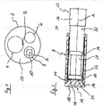
- Fig. 1 shows the distal end of a shaft 2 of an endoscopic shaft instrument. At this distal end of the shaft 2 opens a running through the entire shaft 2 working channel 4.
- the working channel 4 is primarily used to guide a used in conjunction with the shaft instrument, not shown auxiliary instrument to a distal side of the shaft 2 location.
- an image sensor unit 6 is arranged in the region of the distal end of the shaft 2 and an electronic component 10 in the form of an LED chip in a glass sleeve 8.
- the LED chip serves to illuminate a region located distally on the shaft 2.
- Glass sleeve 8 shown in detail which electrically isolates the LED chip arranged therein with respect to its outer environment, is formed as a hollow cylinder and closed by a cover 12 at its distal end.
- a cover 12 on the axially projecting cylindrical projection 14 whose outer diameter corresponds to the inner diameter of the glass sleeve 8 engages the glass formed cover 12 in the distal end of the glass sleeve 8, wherein a relation to the projection 14 radially enlarged portion 16 on the distal end of the glass sleeve 8 rests.
- the cover 12 is integrally connected to the glass sleeve 8 by means of an adhesive bond.
- the glass sleeve 8 is arranged such that a central axis A of the glass sleeve 8 is aligned parallel to a central axis B of the shaft 2.
- the glass sleeve 8 is arranged in the shaft 2 so that an outer side 18 of the glass sleeve 8 distal-closing cover 12 is flush with a distal end face 20 of the shaft 2.
- the LED chip is arranged in the glass sleeve 8 with a small distance to the cover 12 and is supported on the proximal side on a coaxial cable 22, which is guided through the entire shaft 2 and the LED chip with a proximal side of the shaft 2 arranged in the Drawing not shown DC voltage source connects.
- the coaxial cable 22 is shown cut, so that an inner conductor 28, an insulating sheath surrounding the inner conductor 22 on the outside 34, an outer conductor 32 and an outer insulation sheath 36 of the coaxial cable 22 become clear.
- the LED chip For electrical connection of the LED chip with the DC voltage source, the LED chip has on its light-emitting distal side 24 and on its proximal side 26 each have a connection contact, wherein the connection contacts are also not apparent from the drawing.
- the connection contact formed on the proximal side 26 of the LED chip is contacted by the inner conductor 28 of the coaxial cable 22, while the connection contact arranged on the distal side 24 of the LED chip is electrically conductively connected via a conductor 30 to an outer conductor 32 of the coaxial cable 22 ,
- the conductor 30 connecting the LED chip to the outer conductor 32 of the coaxial cable 22 is formed by a metallic sleeve.
- This sleeve is arranged so that it outside the LED chip, d. H. surrounds the outside and surrounds the outer conductor 32 of the coaxial cable 22 contacting in a distal end portion of the coaxial cable 22 on the outside. In this case, the sleeve is completely covered radially on the outside by the glass sleeve 8.
- the sleeve forming the conductor 30 has a web 38 protruding from the rest of the sleeve, which is angled transversely to the longitudinal extent of the sleeve for contacting the connection contact arranged on the distal side 24 of the LED chip.
- the in the Fig. 3-5 illustrated glass sleeve 8 ' is also used for electrical shielding at least one in the glass sleeve 8' arranged LED chip 10 with respect to the outside environment.
- the glass sleeve 8 ' is monolithic, wherein a peripheral part 40 is closed at its distal end by a cover 12'.
- the cross section of the glass sleeve 8 ' is sickle-shaped, with a convex curved wall portion 42 rounded into a concave curved wall portion 44 passes.
- a plurality of concave recesses 48 are formed, each forming a plano-concave lens.
- plano-concave lenses serve to scatter the light emitted by at least one LED chip arranged in the glass sleeve 8 'on the distal side of the glass sleeve 8' so as to bring about a homogeneous light distribution.
Abstract
Die Erfindung betrifft ein endoskopisches Schaftinstrument, welches im Bereich seines distalen Endes zumindest ein elektronisches Bauteil mit einem außenseitig liegenden Leiter aufweist. Das elektronische Bauteil ist zumindest außenumfänglich von einer Glashülse umgeben.The invention relates to an endoscopic shaft instrument which has at least one electronic component with an outside conductor in the region of its distal end. The electronic component is surrounded at least externally by a glass sleeve.
Description
Die Erfindung betrifft ein endoskopisches Schaftinstrument mit den im Oberbegriff von Anspruch 1 angegebenen Merkmalen.The invention relates to an endoscopic shaft instrument having the features specified in the preamble of claim 1.
Ausgangspunkt der Erfindung sind solche endoskopischen Instrumente, bei denen im Bereich des distalen Endes eines in den Körper eines Patienten einzuführenden Schaftes elektronische Bauteile angeordnet sind. Diese elektronischen Bauteile können beispielsweise Teil einer Beleuchtungs- oder Beobachtungseinrichtung sowie Teil einer Therapieeinrichtung sein.Starting point of the invention are those endoscopic instruments in which electronic components are arranged in the region of the distal end of a shaft to be introduced into the body of a patient. These electronic components may be part of a lighting or observation device and part of a therapy device, for example.
In Verbindung mit Instrumenten dieser Art ist es generell erforderlich, einen unbeabsichtigten Strompfad von den elektronischen Bauteilen zu einem mit dem Instrument zu behandelnden Patienten zu verhindern. Bei Instrumenten mit einem metallischen Schaft bzw. mit einem die elektronischen Bauteile radial umgebenden metallischen distalen Endabschnitt des Schaftes kann beispielsweise ein solcher Strompfad von einem elektronischen Bauteil zu dem Patienten über die metallische und damit elektrisch leitende Außenwandung des Schaftes erfolgen. Es ist daher notwendig, im Bereich des distalen Instrumentenendes angeordnete elektronische Bauteile gegenüber der Außenwandung des Schaftes elektrisch zu isolieren. Zu diesem Zweck werden üblicherweise Kunststoffmassen bzw. Kunststoffbauteile verwendet, welche die elektronischen Bauteile außenseitig ummanteln. In Abhängigkeit von einem erforderlichen Isolationswiderstand sowie herstellungsbedingt sind diese Kunststoffummantelungen allerdings vergleichsweise dickwandig, was sich unmittelbar auf die Abmessungen des Schaftes auswirkt. D. h., dass die elektrisch isolierende Ummantelung der elektronischen Bauteile im Normalfall immer einen vergleichsweise großen Schaftquerschnitt bedingt, obwohl es bei endoskopischen Instrumenten eigentlich anzustreben ist, den Schaftquerschnitt möglichst klein zu halten.In connection with instruments of this type, it is generally necessary to prevent an unintended current path from the electronic components to a patient to be treated with the instrument. In the case of instruments with a metallic shaft or with a metallic distal end section of the shaft radially surrounding the electronic components, for example, such a current path can take place from an electronic component to the patient via the metallic and thus electrically conductive outer wall of the shaft. It is therefore necessary to electrically isolate electronic components arranged in the region of the distal instrument end with respect to the outer wall of the shaft. For this purpose, plastic compounds or plastic components are usually used, which encase the electronic components on the outside. Depending on a required insulation resistance and production reasons, however, these plastic sheaths are comparatively thick-walled, which has a direct effect on the dimensions of the shank. This means that the electrically insulating sheath of the electronic components normally always requires a comparatively large shank cross-section, although it is actually desirable in endoscopic instruments to keep the shank cross-section as small as possible.
Vor diesem Hintergrund liegt der Erfindung die Aufgabe zugrunde, ein endoskopisches Instrument der eingangs beschriebenen Art zu schaffen, welches bei möglichst kleinen lateralen Abmessungen an seinem distalen Endabschnitt eine ausreichende elektrische Isolierung von im Bereich des distalen Endes des Instruments angeordneten elektronischen Bauteilen gewährleistet.Against this background, the invention has the object to provide an endoscopic instrument of the type described above, which ensures sufficient electrical insulation of arranged in the region of the distal end of the instrument electronic components at the smallest possible lateral dimensions at its distal end portion.
Diese Aufgabe wird durch ein endoskopisches Schaftinstrument mit den in Anspruch 1 angegebenen Merkmalen gelöst, wobei sich vorteilhafte Weiterbildungen dieses Schaftinstrumentes aus den Unteransprüchen, der nachfolgenden Beschreibung sowie aus den Zeichnungen ergeben. Hierbei können die in den Unteransprüchen angegebenen Merkmale vorteilhaft in der angegebenen Kombination, aber auch, soweit technisch sinnvoll, für sich oder in anderer Kombination zur Ausgestaltung der Erfindung beitragen.This object is achieved by an endoscopic shaft instrument having the features specified in claim 1, wherein advantageous developments of this Schaftinstrumentes from the dependent claims, the following description and from the drawings. In this case, the features specified in the subclaims can advantageously contribute in the specified combination, but also, as far as is technically meaningful, alone or in another combination for the embodiment of the invention.
Das erfindungsgemäße endoskopische Schaftinstrument weist im Bereich seines distalen Endes, d. h. im Bereich des distalen Endes seines Schaftes zumindest ein elektronisches Bauteil mit einem außenseitig liegenden elektrischen Leiter auf. Das elektronische Bauteil kann z. B. Bestandteil einer in dem distalen Endbereich des Schaftes angeordneten Beleuchtungs-, Beobachtungs- oder Therapieeinrichtung sein. Der außenseitig an dem Bauteil liegende Leiter dient vorzugsweise zur Spannungsversorgung des Bauteils und ist zu diesem Zweck mit einer zu einer Spannungsquelle führenden, durch den Schaft geführten elektrischen Leitung verbunden.In the region of its distal end, ie in the region of the distal end of its shaft, the endoscopic shaft instrument according to the invention has at least one electronic component with an electrical conductor on the outside. The electronic component can, for. B. be part of a arranged in the distal end portion of the shaft lighting, observation or therapy device. The conductor located on the outside on the component is preferably used to supply the voltage to the component and is connected for this purpose to an electrical line leading to a voltage source and guided through the shaft.
Die Besonderheit der Erfindung besteht darin, dass das zumindest eine elektronische Bauteil zumindest außenumfänglich von einer Glashülse umgeben ist. Weist das erfindungsgemäße Schaftinstrument im Bereich des distalen Endes seines Schaftes mehrere gegenüber der Außenumgebung elektrisch zu isolierende elektronische Bauteile auf, so können diese jeweils außenumfänglich von einer Glashülse umgeben sein oder es können mehrere elektronische Bauteile außenumfänglich von einer Glashülse umgeben sein, also in einer Glashülse mehrere elektronische Bauteile angeordnet sein.The peculiarity of the invention is that the at least one electronic component is surrounded at least externally by a glass sleeve. If the shaft instrument according to the invention has several electronic components to be electrically insulated from the outside environment in the region of the distal end of its shaft, they can each be surrounded by a glass sleeve on the outside, or several electronic components can be surrounded by a glass sleeve on the outside, ie several in a glass sleeve be arranged electronic components.
Die das zumindest eine elektronische Bauteil außenumfänglich umgebende Hülse ist in dem Schaft zweckmäßigerweise derart angeordnet, dass ihre Mittelachse im Wesentlichen parallel zur Schaftmittelachse ausgerichtet ist, d. h. die Wandung der Glashülse ist zwischen dem elektronischen Bauteil mit seinem außenseitig liegenden elektrischen Leiter und der Außenwandung des Schaftes angeordnet und bildet somit einen zwischen dem elektronischen Bauteil und der Außenwandung des Schaftes angeordneten elektrischen Isolator, der einen Stromübergang von dem elektronischen Bauteil bzw. von dem außenseitig des Bauteils liegenden elektrischen Leiter auf die Außenwandung des Schaftes verhindert. Hierbei erweist es sich als vorteilhaft, dass die Glashülse aufgrund der guten elektrischen Isolationseigenschaften von Glas sehr dünnwandig ausgebildet sein kann und auch sehr dünnwandig herstellbar ist. Es kann somit eine elektrische Isolation des elektronischen Bauteils geschaffen werden, die sich in deutlich geringerem Maße auf die radialen Abmessungen des Schaftes auswirkt, als dies bei den aus dem Stand der Technik bekannten endoskopischen Schaftinstrumenten der in Rede stehenden Art der Fall ist.The sleeve which surrounds the outer circumference of the at least one electronic component is expediently arranged in the shaft in such a way that its central axis is aligned substantially parallel to the shaft center axis, that is to say in the case of the shaft. H. the wall of the glass sleeve is disposed between the electronic component with its external electrical conductor and the outer wall of the shaft and thus forms an electrical insulator arranged between the electronic component and the outer wall of the shaft, which is a current transfer from the electronic component or from the outside the component lying electrical conductor prevents the outer wall of the shaft. It proves to be advantageous that the glass sleeve can be made very thin-walled due to the good electrical insulation properties of glass and also very thin-walled produced. It can thus be provided an electrical insulation of the electronic component, which affects the radial dimensions of the shaft to a much lesser extent, as is the case with the known from the prior art endoscopic shaft instruments of the type in question.
Bevorzugt ist die Glashülse an ihrem distalen Ende von einer Abdeckung verschlossen. Diese gestalterische Maßnahme dient vorrangig zum Schutz eines in der Glashülse angeordneten elektronischen Bauteils und ist beispielsweise dann von Vorteil, wenn das distale Ende des erfindungsgemäßen Schaftinstrumentes in Richtung des elektronischen Bauteiles offen ausgebildet ist. In diesem Fall wird das Bauteil von der Abdeckung einerseits mechanisch geschützt und andererseits von gegebenenfalls in der Außenumgebung des distalen Schaftendes befindlichen Flüssigkeiten wie beispielsweise einer in Verbindung mit dem Schaftinstrument eingesetzten Spülflüssigkeit abgeschirmt, welche ansonsten auch einen unerwünschten Strompfad von dem elektronischen Bauteil zu einem mit dem Schaftinstrument zu behandelnden Patienten und unerwünschte Strompfade an dem elektronischen Bauteil selbst bilden könnte. Die Abdeckung ist daher vorzugsweise ebenfalls aus einem elektrisch nicht leitenden Material ausgebildet. Ein weiterer Vorteil der an dem distalen Ende der Glashülse angeordneten Abdeckung besteht darin, dass sie die möglichst dünnwandig ausgebildete Glashülse versteift und somit deren Stabilität erhöht.Preferably, the glass sleeve is closed at its distal end by a cover. This design measure serves primarily to protect an arranged in the glass sleeve electronic component and is for example advantageous if the distal end of the shank instrument according to the invention is designed to be open in the direction of the electronic component. In this case, the component of the cover on the one hand mechanically protected and on the other hand shielded by possibly located in the outer environment of the distal end of the shaft fluids such as a flushing liquid used in conjunction with the shaft instrument, which otherwise also an undesirable current path from the electronic component to one with the Shank instrument to be treated patients and unwanted current paths on the electronic component itself could form. The cover is therefore preferably also formed of an electrically non-conductive material. A further advantage of the cover arranged at the distal end of the glass sleeve is that it stiffens the thin-walled glass sleeve and thus increases its stability.
Weiter bevorzugt ist die das distale Ende der Glashülse verschließende Abdeckung eine Glasabdeckung. Die Verwendung einer Glasabdeckung ist typischerweise dann zweckmäßig, wenn das in der Glashülse angeordnete elektronische Bauteil ein zur Emission oder Aufnahme von Licht bereitgestelltes Bauteil ist, wobei die Glasabdeckung einen Lichtdurchgang von dem elektronischen Bauteil zu der distalen Außenumgebung des Schaftinstrumentes und umgekehrt ermöglicht. Die Glashülse kann an ihren beiden Flachseiten planparallel eben ausgebildet sein oder zur Bildung eines lichtablenkenden optischen Bauteils, zueinander schräg ausgerichtete ebene Flachseiten aufweisen oder an mindestens einer ihrer Flachseiten eine konvexe oder konkave Wölbung aufweisen.More preferably, the covering the distal end of the glass sleeve cover is a glass cover. The use of a glass cover is typically useful when the electronic component disposed within the glass sleeve is a component for emitting or receiving light, the glass cover allowing light to pass from the electronic component to the distal exterior environment of the shank instrument and vice versa. The glass sleeve can be plane-parallel formed flat on its two flat sides or have to form a light-deflecting optical component, mutually obliquely aligned flat flat sides or on at least one of its flat sides have a convex or concave curvature.
Gemäß einer weiteren bevorzugten Weiterbildung der Erfindung sind die Glashülse und die Abdeckung separate Teile, welche stoffschlüssig miteinander verbunden sind. Zur stoffschlüssigen Verbindung von Glashülse und Abdeckung kann die Abdeckung lediglich plan auf dem distalen Ende der Glashülse aufliegend mit der Glashülse verklebt sein. Bevorzugt ist allerdings vorgesehen, dass die Abdeckung mit einem mit dem Innenquerschnitt der Glashülse korrespondierenden Abschnitt in die Glashülse eingreift und in dieser Position mit der Glashülse verklebt ist, wobei der in das distale Ende der Hülse eingreifende Absatz die Stabilität der Glashülse in besonderem Maße erhöht. Die Verwendung von separaten, die Glashülse und die Abdeckung bildenden Teilen ist beispielsweise dann angebracht, wenn eine Abdeckung vorgesehen ist, die aus einem anderen Material als Glas oder aus einer Kombination mehrerer Materialen ausgebildet ist. Unabhängig davon, ob die Abdeckung aus Glas oder einem anderen Material bzw. anderen Materialien ausgebildet ist, erweist es sich aber als vorteilhaft, dass eine distalseitig von einer Abdeckung verschlossene Glashülse bei Verwendung zweier separater Teile verhältnismäßig einfach herstellbar ist, indem lediglich auf einem die Glashülse bildenden Glasröhrchen ein die Abdeckung bildendes Plättchen aufgeklebt werden muss. Hinsichtlich einer sicheren, spannungsfreien Klebverbindung zwischen der Glashülse und der Abdeckung ist es von Vorteil, wenn die Abdeckung aus Glas ausgebildet ist und somit mit der Glashülse identische oder zumindest weitestgehend identische Werkstoffeigenschaften wie beispielsweise einen zumindest annähernd gleichen Ausdehnungskoeffizienten aufweist.According to a further preferred embodiment of the invention, the glass sleeve and the cover are separate parts, which are materially interconnected. For cohesive connection of glass sleeve and cover, the cover can only be glued lying flat on the distal end of the glass sleeve with the glass sleeve. Preferably, however, it is provided that the cover engages with a corresponding with the inner cross section of the glass sleeve portion in the glass sleeve and is glued in this position with the glass sleeve, wherein the engaging in the distal end of the sleeve heel increases the stability of the glass sleeve to a particular extent. The use of separate, the glass sleeve and the cover forming parts is for example appropriate when a cover is provided, which is formed of a material other than glass or a combination of several materials. Regardless of whether the cover is formed of glass or another material or other materials, it proves to be advantageous that a glass sleeve closed distally from a cover when using two separate parts is relatively easy to produce by only one on the glass sleeve forming glass tube a covering forming plate must be stuck. With regard to a secure, stress-free adhesive bond between the glass sleeve and the cover, it is advantageous if the cover is formed of glass and thus with the glass sleeve identical or at least largely identical material properties such as having at least approximately the same coefficient of expansion.
In einer alternativen Ausgestaltung zu einer von der Glashülse separaten Abdeckung und zumindest im Hinblick auf eine Reduzierung der Teilezahl des Schaftinstruments günstig ist erfindungsgemäß weiter vorgesehen, dass ein monolithisches Bauteil die Glashülse und die Abdeckung bildet. Dementsprechend ist das elektronische Bauteil in einem hülsenförmigen und an einer Stirnseite verschlossen ausgebildeten Glaskörper angeordnet. Ein Verlust der distalen Abdeckung ist in diesem Fall quasi vollständig auszuschließen.In an alternative embodiment to a separate from the glass sleeve cover and low, at least with a view to reducing the number of parts of the shank instrument according to the invention further provided that a monolithic component forms the glass sleeve and the cover. Accordingly, the electronic component is arranged in a sleeve-shaped and closed on a front side formed glass body. A loss of distal coverage is almost completely ruled out in this case.
Vorteilhaft kann die Glashülse einen kreisförmigen Querschnitt aufweisen. D. h., die Glashülse wird vorzugsweise von einem hohlzylindrischen Glasrohr gebildet, welches kostengünstig herstellbar und im Handel als Halbzeug kostengünstig erhältlich ist.Advantageously, the glass sleeve may have a circular cross-section. D. h., The glass sleeve is preferably formed by a hollow cylindrical glass tube, which is inexpensive to produce and commercially available as semi-finished cost.
Neben der Verwendung einer Glashülse mit einem kreisförmigen Querschnitt sieht die Erfindung vorteilhaft auch Ausgestaltungen der Glashülse vor, bei welchen diese einen von einer Kreisform abweichenden Querschnitt aufweist. Hierbei kann die Querschnittsform der Glashülse, die generell beliebig ist, z. B. mit den Querschnittsabmessungen des darin angeordneten elektronischen Bauteils korrespondieren. Ferner kann die Querschnittsform der Glashülse auch an weitere Komponenten des endoskopischen Instrumentes, welche in Querschnittsrichtung des Schaftes neben der Glashülse angeordnet sind bzw. an durch den Schaft verlaufende Kanäle, wie beispielsweise Arbeitskanäle zur Durchführung von Hilfsinstrumenten und/oder Spülflüssigkeit, angepasst werden. Insbesondere in diesem Zusammenhang ist bevorzugt vorgesehen, dass die Glashülse einen sichelförmigen Querschnitt aufweist. Hierbei kann die Glashülse an ihrer konvex gewölbten Außenseite einen Außenradius aufweisen, welcher mit dem Innenradius des Schaftes des Schaftinstrumentes korrespondiert, sodass die Glashülse in dem Schaft unmittelbar an der Innenwandung des Schaftes anliegend angeordnet werden kann, wobei ein der konvex gewölbten Außenseite gegenüberliegender konkav gewölbter Bereich der Außenseite dazu führt, dass in dem Schaft außenseitig des konkav gewölbten Bereichs ein vergleichsweise großer Raum für die Anordnung weiterer Komponenten des Schaftinstruments zur Verfügung steht.In addition to the use of a glass sleeve with a circular cross-section, the invention advantageously also provides embodiments of the glass sleeve, in which this has a deviating from a circular cross-section. Here, the cross-sectional shape of the glass sleeve, which is generally arbitrary, z. B. correspond to the cross-sectional dimensions of the electronic component disposed therein. Furthermore, the cross-sectional shape of the glass sleeve can also be adapted to further components of the endoscopic instrument, which are arranged in the cross-sectional direction of the shaft next to the glass sleeve or to channels extending through the shaft, such as working channels for carrying auxiliary instruments and / or rinsing fluid. In particular, in this context, it is preferably provided that the glass sleeve has a crescent-shaped cross section. Here, the glass sleeve may have on its convexly curved outer side an outer radius which corresponds to the inner radius of the shank of the shank instrument, so that the glass sleeve can be arranged in the shank immediately adjacent to the inner wall of the shank, wherein a convexly curved outer side opposite concave curved area the outer side causes a comparatively large space for the arrangement of further components of the shaft instrument to be available in the shaft on the outside of the concavely curved region.
Bevorzugt ist das zumindest eine außenumfänglich von einer Glashülse umgebende Bauteil eine LED. Diese LED dient vorteilhaft zur Ausleuchtung eines distalseitig des Schaftinstrumentes befindlichen Bereiches. Die vorzugsweise vorgesehene Abdeckung, welche die Glashülse an ihrem distalen Ende verschließt, ist hierbei zweckmäßigerweise aus einem lichttransparenten Material und bevorzugt aus Glas ausgebildet. Bei der LED handelt es sich weiter bevorzugt um einen LED-Chip, welcher zumindest einen außenseitig der LED angeordneten Leiter aufweist, der einen an der lichtemittierenden Seite an der LED vorgesehenen Anschlusskontakt mit einem Pol einer Gleichspannungsquelle leitungsverbindet. Die Glashülse und deren distalseitige Abdeckung schirmen die LED und insbesondere deren außenseitig liegenden Leiter gegenüber dem Schaft des Schaftinstrumentes elektrisch isolierend ab, wobei die Glashülse und deren Abdeckung auch in gewissem Grade thermisch isolierend wirken, so dass die von der LED abgestrahlte Wärme vor allem bei gleichzeitiger Wärmeabfuhr durch das Innere des Schaftes in proximaler Richtung nicht oder nur in geringem Maße in die radiale und distale Außenumgebung der Glashülse gelangt.Preferably, the at least one outer circumference of a glass sleeve surrounding component is an LED. This LED is advantageously used to illuminate an area located on the distal side of the shaft instrument. The preferably provided cover which the glass sleeve Closing at its distal end, this is expediently formed of a light-transparent material and preferably of glass. The LED is furthermore preferably an LED chip which has at least one conductor arranged on the outside of the LED, which line connection connects a terminal contact provided on the light-emitting side to the LED to a pole of a DC voltage source. The glass sleeve and its distal cover shield the LED and in particular their outside conductors against the shaft of the shank instrument from electrically insulating, the glass sleeve and its cover also act to some extent thermally insulating, so that the radiated heat from the LED, especially at the same time Heat dissipation through the interior of the shaft in the proximal direction does not or only slightly reaches the radial and distal outer environment of the glass sleeve.
Gemäß einer weiteren bevorzugten Weiterbildung der Erfindung sind an der vorzugsweise die Glashülse an ihrem distalen Ende verschließenden Abdeckung mehrere optische Linsen ausgebildet. Dementsprechend sind an der Abdeckung über deren Querschnittsfläche verteilt eine Vielzahl von Linsen vorgesehen, die bei einer Abdeckung aus einem lichttransparenten Material durch einen entsprechenden Anschliff der Abdeckung ausgebildet sein können, gegebenenfalls aber auch von separaten Teilen gebildet werden können, welche in der Abdeckung eingesetzt sind oder auf die Abdeckung aufgesetzt sind.According to a further preferred development of the invention, a plurality of optical lenses are formed on the cover which preferably closes the glass sleeve at its distal end. Accordingly, a plurality of lenses are provided on the cover over the cross-sectional area distributed, which may be formed in a cover of a light transparent material by a corresponding bevel of the cover, but may also be formed by separate parts which are inserted in the cover or are placed on the cover.
Bei den an der Abdeckung ausgebildeten Linsen kann es sich sowohl um Sammel- als auch um Zerstreuungslinsen handeln. Die Verwendung von Zerstreuungslinsen ist insbesondere in Verbindung mit einer in der Glashülse angeordneten LED einer Beleuchtungseinrichtung vorteilhaft, bei welcher mit der Zerstreuungslinse eine homogene Verteilung des von der LED emittierten Lichtes bewirkt werden kann. So sind die Linsen bevorzugt konkave Linsen und vorzugsweise plan-konkave Linsen. In letztgenanntem Fall ist vorrangig vorgesehen, dass an der aus einem lichtdurchlässigen Material ausgebildeten Abdeckung an der der Glashülse zugewandten Flachseite mehrere konkave Vertiefungen ausgebildet sind.The lenses formed on the cover can be both collecting lenses and diverging lenses. The use of diverging lenses is particularly advantageous in connection with an LED of an illumination device arranged in the glass sleeve, in which a homogeneous distribution of the light emitted by the LED can be effected with the diverging lens. So are the lenses preferably concave lenses and preferably plano-concave lenses. In the latter case, it is primarily provided that a plurality of concave depressions are formed on the cover formed of a light-transmitting material on the flat side facing the glass sleeve.
Nachfolgend ist die Erfindung anhand von in den Zeichnungen dargestellten Ausführungsbeispielen näher erläutert. In den Zeichnungen zeigt jeweils schematisch stark vereinfacht und in unterschiedlichen Maßstäben:
- Fig. 1:
- in einer Draufsicht ein distales Ende eines endoskopischen Schaftinstrumentes,
- Fig. 2:
- in einer geschnittenen Seitenansicht eine in einer Glashülse angeordnete LED des Schaftinstrumentes nach
Fig. 1 , - Fig. 3:
- in perspektivischer Darstellung eine Glashülse zur Aufnahme einer LED gemäß einer zweiten Ausgestaltung,
- Fig. 4:
- die Glashülse nach
Fig. 3 in einer geschnittenen Seitenansicht und - Fig. 5:
- die Glashülse nach
Fig. 3 in einer Untersicht.
- Fig. 1:
- in a plan view, a distal end of an endoscopic shaft instrument,
- Fig. 2:
- in a sectional side view arranged in a glass sleeve LED of the Schaftinstrumentes after
Fig. 1 . - 3:
- a perspective view of a glass sleeve for receiving an LED according to a second embodiment,
- 4:
- the glass sleeve after
Fig. 3 in a sectional side view and - Fig. 5:
- the glass sleeve after
Fig. 3 in a soffit.
Die in
In dem Schaft 2 ist die Glashülse 8 derart angeordnet, dass eine Mittelachse A der Glashülse 8 parallel zu einer Mittelachse B des Schaftes 2 ausgerichtet ist. Zudem ist die Glashülse 8 in dem Schaft 2 so angeordnet, dass eine Außenseite 18 der die Glashülse 8 distalseitig verschließenden Abdeckung 12 bündig mit einer distalen Stirnseite 20 des Schaftes 2 fluchtet.In the
Der LED-Chip ist in der Glashülse 8 mit geringem Abstand zu der Abdeckung 12 angeordnet und stützt sich proximalseitig auf einem Koaxialkabel 22 ab, welches durch den gesamten Schaft 2 geführt ist und den LED-Chip mit einer proximalseitig des Schaftes 2 angeordneten, in der Zeichnung nicht dargestellten Gleichspannungsquelle verbindet. In
Der den LED-Chip mit dem Außenleiter 32 des Koaxialkabels 22 verbindende Leiter 30 wird von einer metallischen Hülse gebildet. Diese Hülse ist derart angeordnet, dass sie den LED-Chip außenseitig, d. h. außenumfänglich umgibt und auch den Außenleiter 32 des Koaxialkabels 22 kontaktierend in einem distalen Endabschnitt des Koaxialkabels 22 außenseitig umgibt. Hierbei wird die Hülse radial außenseitig vollständig von der Glashülse 8 überdeckt. An ihrem distalen Ende weist die den Leiter 30 bildende Hülse einen gegenüber der übrigen Hülse vorstehenden Steg 38 auf, welcher zur Kontaktierung des an der distalen Seite 24 des LED-Chips angeordneten Anschlusskontakts quer zur Längsausdehnung der Hülse abgewinkelt ist.The
Die in den
- 22
- Schaftshaft
- 44
- Arbeitskanalworking channel
- 66
- BildsensoreinheitImage sensor unit
- 8, 8'8, 8 '
- Glashülseglass sleeve
- 1010
- elektronisches Bauteilelectronic component
- 12, 12'12, 12 '
- Abdeckungcover
- 1414
- Vorsprunghead Start
- 1616
- Abschnittsection
- 1818
- Außenseiteoutside
- 2020
- Stirnseitefront
- 2222
- Koaxialkabelcoaxial
- 2424
- Seitepage
- 2626
- Seitepage
- 2828
- Innenleiterinner conductor
- 3030
- Leiterladder
- 3232
- Außenleiterouter conductor
- 3434
- Isolationsummantelunginsulation sheathing
- 3636
- Isolationsummantelunginsulation sheathing
- 3838
- Stegweb
- 4040
- Umfangsteilperipheral part
- 4242
- Wandungsbereichwall region
- 4444
- Wandungsbereichwall region
- 4646
- Seitepage
- 4848
- Vertiefungdeepening
- AA
- Mittelachsecentral axis
- BB
- Mittelachsecentral axis
Claims (10)
Priority Applications (1)
| Application Number | Priority Date | Filing Date | Title |
|---|---|---|---|
| PL17156366T PL3210521T3 (en) | 2016-02-24 | 2017-02-15 | Endoscopic shaft instrument |
Applications Claiming Priority (1)
| Application Number | Priority Date | Filing Date | Title |
|---|---|---|---|
| DE102016202819.7A DE102016202819A1 (en) | 2016-02-24 | 2016-02-24 | Endoscopic shaft instrument |
Publications (2)
| Publication Number | Publication Date |
|---|---|
| EP3210521A1 true EP3210521A1 (en) | 2017-08-30 |
| EP3210521B1 EP3210521B1 (en) | 2019-12-04 |
Family
ID=58054029
Family Applications (1)
| Application Number | Title | Priority Date | Filing Date |
|---|---|---|---|
| EP17156366.1A Active EP3210521B1 (en) | 2016-02-24 | 2017-02-15 | Endoscopic shaft instrument |
Country Status (4)
| Country | Link |
|---|---|
| EP (1) | EP3210521B1 (en) |
| DE (1) | DE102016202819A1 (en) |
| ES (1) | ES2774129T3 (en) |
| PL (1) | PL3210521T3 (en) |
Cited By (1)
| Publication number | Priority date | Publication date | Assignee | Title |
|---|---|---|---|---|
| CN114222607A (en) * | 2019-08-14 | 2022-03-22 | 理查德·沃尔夫有限公司 | Optical therapeutic device |
Citations (8)
| Publication number | Priority date | Publication date | Assignee | Title |
|---|---|---|---|---|
| US4778247A (en) * | 1984-05-04 | 1988-10-18 | Warner Lambert Technologies, Inc. | Molded objective head for fiberscopes with integral lenses |
| US5337734A (en) * | 1992-10-29 | 1994-08-16 | Advanced Polymers, Incorporated | Disposable sheath with optically transparent window formed continuously integral therewith |
| EP1467416A2 (en) * | 2003-04-11 | 2004-10-13 | Weldon Technologies, Inc. | High power light emitting diode |
| US20070249907A1 (en) * | 2006-04-20 | 2007-10-25 | Boulais Dennis R | Imaging assembly with transparent distal cap |
| CN201044740Y (en) * | 2007-03-01 | 2008-04-09 | 范力 | Household endoscope |
| DE102013201808A1 (en) * | 2013-02-05 | 2014-08-07 | Richard Wolf Gmbh | LED lighting module |
| US20150005580A1 (en) * | 2008-12-10 | 2015-01-01 | Ambu A/S | Endoscope having a camera housing and method for making a camera housing |
| CN204863074U (en) * | 2015-06-26 | 2015-12-16 | 安姣 | General speculum device for internal medicine |
Family Cites Families (3)
| Publication number | Priority date | Publication date | Assignee | Title |
|---|---|---|---|---|
| DD10387A5 (en) * | 1951-11-11 | 1955-09-01 | Firma Hans Kollmorgen Gmbh | LIGHTING DEVICE FOR INSPECTION AND TREATMENT INSTRUMENTS FOR HOLLOW ROOMS e.g. ANIMAL BODIES |
| JPH07104494B2 (en) * | 1987-06-26 | 1995-11-13 | オリンパス光学工業株式会社 | Illumination optical system for endoscope |
| DE20309759U1 (en) * | 2003-06-25 | 2003-09-04 | Wolf Gmbh Richard | Medical endoscope |
-
2016
- 2016-02-24 DE DE102016202819.7A patent/DE102016202819A1/en not_active Withdrawn
-
2017
- 2017-02-15 EP EP17156366.1A patent/EP3210521B1/en active Active
- 2017-02-15 PL PL17156366T patent/PL3210521T3/en unknown
- 2017-02-15 ES ES17156366T patent/ES2774129T3/en active Active
Patent Citations (8)
| Publication number | Priority date | Publication date | Assignee | Title |
|---|---|---|---|---|
| US4778247A (en) * | 1984-05-04 | 1988-10-18 | Warner Lambert Technologies, Inc. | Molded objective head for fiberscopes with integral lenses |
| US5337734A (en) * | 1992-10-29 | 1994-08-16 | Advanced Polymers, Incorporated | Disposable sheath with optically transparent window formed continuously integral therewith |
| EP1467416A2 (en) * | 2003-04-11 | 2004-10-13 | Weldon Technologies, Inc. | High power light emitting diode |
| US20070249907A1 (en) * | 2006-04-20 | 2007-10-25 | Boulais Dennis R | Imaging assembly with transparent distal cap |
| CN201044740Y (en) * | 2007-03-01 | 2008-04-09 | 范力 | Household endoscope |
| US20150005580A1 (en) * | 2008-12-10 | 2015-01-01 | Ambu A/S | Endoscope having a camera housing and method for making a camera housing |
| DE102013201808A1 (en) * | 2013-02-05 | 2014-08-07 | Richard Wolf Gmbh | LED lighting module |
| CN204863074U (en) * | 2015-06-26 | 2015-12-16 | 安姣 | General speculum device for internal medicine |
Cited By (2)
| Publication number | Priority date | Publication date | Assignee | Title |
|---|---|---|---|---|
| CN114222607A (en) * | 2019-08-14 | 2022-03-22 | 理查德·沃尔夫有限公司 | Optical therapeutic device |
| CN114222607B (en) * | 2019-08-14 | 2024-02-06 | 理查德·沃尔夫有限公司 | Light therapeutic equipment |
Also Published As
| Publication number | Publication date |
|---|---|
| PL3210521T3 (en) | 2020-05-18 |
| ES2774129T3 (en) | 2020-07-16 |
| EP3210521B1 (en) | 2019-12-04 |
| DE102016202819A1 (en) | 2017-08-24 |
Similar Documents
| Publication | Publication Date | Title |
|---|---|---|
| EP2818127B1 (en) | Electrosurgical instrument with light guide | |
| DE102013001156B4 (en) | Bipolar resectoscope | |
| DE102007009725B4 (en) | High frequency treatment instrument for an endoscope | |
| EP2476455A1 (en) | Implantable electrode lead | |
| DE1764790A1 (en) | Electrodes that can be implanted in the living body | |
| EP1296606A1 (en) | Electrode configuration for a surgical instrument | |
| DE3600283A1 (en) | ENDOSCOPE | |
| EP2953519B1 (en) | Led lighting module | |
| DE102007053398B4 (en) | Treatment instrument for an endoscope | |
| DE10030482B4 (en) | endoscope | |
| DE10042095C1 (en) | Urological rectoscope has sliding body provided with transverse bore for 2-part clamp block for electrode carrier for HF electrode | |
| DE102019118824A1 (en) | endoscope | |
| EP3210521B1 (en) | Endoscopic shaft instrument | |
| DE102015106049A1 (en) | Lighting device with side-emitting light-conducting fiber bundle | |
| DE102010044786A1 (en) | Rigid video endoscope with insulating conductor carrier | |
| DE102012102271A1 (en) | Endoscopic surgical instrument | |
| DE102004009383A1 (en) | Rigid endoscope optics with multi-part housing | |
| DE102019100144A1 (en) | Endoscope and position securing element | |
| DE3214487A1 (en) | Cable bushing for RF energy | |
| DE102011105442A1 (en) | Laboratory use for an endoscopic hollow-shaft instrument | |
| DE102016008903A1 (en) | Coupler between a coaxial connector and a coaxial cable | |
| DE102012009058B4 (en) | Bipolar electrode connection | |
| DE202006001255U1 (en) | Endoscope in particular with electrically operated components, comprising inner shaft at maximal distance to outer shaft | |
| EP1897510A1 (en) | High frequency endoscopic instrument | |
| DE102010018818A1 (en) | Surgical instrument i.e. laparoscopic shaft instrument, for operation into abdominal cavity of human body, has shaft provided with coating of inner and outer layers with colors, where outer layer is opaque in color |
Legal Events
| Date | Code | Title | Description |
|---|---|---|---|
| PUAI | Public reference made under article 153(3) epc to a published international application that has entered the european phase |
Free format text: ORIGINAL CODE: 0009012 |
|
| STAA | Information on the status of an ep patent application or granted ep patent |
Free format text: STATUS: THE APPLICATION HAS BEEN PUBLISHED |
|
| AK | Designated contracting states |
Kind code of ref document: A1 Designated state(s): AL AT BE BG CH CY CZ DE DK EE ES FI FR GB GR HR HU IE IS IT LI LT LU LV MC MK MT NL NO PL PT RO RS SE SI SK SM TR |
|
| AX | Request for extension of the european patent |
Extension state: BA ME |
|
| STAA | Information on the status of an ep patent application or granted ep patent |
Free format text: STATUS: REQUEST FOR EXAMINATION WAS MADE |
|
| 17P | Request for examination filed |
Effective date: 20180220 |
|
| RBV | Designated contracting states (corrected) |
Designated state(s): AL AT BE BG CH CY CZ DE DK EE ES FI FR GB GR HR HU IE IS IT LI LT LU LV MC MK MT NL NO PL PT RO RS SE SI SK SM TR |
|
| STAA | Information on the status of an ep patent application or granted ep patent |
Free format text: STATUS: EXAMINATION IS IN PROGRESS |
|
| 17Q | First examination report despatched |
Effective date: 20180622 |
|
| GRAP | Despatch of communication of intention to grant a patent |
Free format text: ORIGINAL CODE: EPIDOSNIGR1 |
|
| STAA | Information on the status of an ep patent application or granted ep patent |
Free format text: STATUS: GRANT OF PATENT IS INTENDED |
|
| INTG | Intention to grant announced |
Effective date: 20190712 |
|
| GRAS | Grant fee paid |
Free format text: ORIGINAL CODE: EPIDOSNIGR3 |
|
| GRAA | (expected) grant |
Free format text: ORIGINAL CODE: 0009210 |
|
| STAA | Information on the status of an ep patent application or granted ep patent |
Free format text: STATUS: THE PATENT HAS BEEN GRANTED |
|
| AK | Designated contracting states |
Kind code of ref document: B1 Designated state(s): AL AT BE BG CH CY CZ DE DK EE ES FI FR GB GR HR HU IE IS IT LI LT LU LV MC MK MT NL NO PL PT RO RS SE SI SK SM TR |
|
| REG | Reference to a national code |
Ref country code: GB Ref legal event code: FG4D Free format text: NOT ENGLISH |
|
| REG | Reference to a national code |
Ref country code: CH Ref legal event code: EP |
|
| REG | Reference to a national code |
Ref country code: AT Ref legal event code: REF Ref document number: 1208357 Country of ref document: AT Kind code of ref document: T Effective date: 20191215 |
|
| REG | Reference to a national code |
Ref country code: DE Ref legal event code: R096 Ref document number: 502017003018 Country of ref document: DE |
|
| REG | Reference to a national code |
Ref country code: IE Ref legal event code: FG4D Free format text: LANGUAGE OF EP DOCUMENT: GERMAN |
|
| REG | Reference to a national code |
Ref country code: CH Ref legal event code: NV Representative=s name: ISLER AND PEDRAZZINI AG, CH |
|
| REG | Reference to a national code |
Ref country code: SE Ref legal event code: TRGR |
|
| REG | Reference to a national code |
Ref country code: NL Ref legal event code: FP |
|
| REG | Reference to a national code |
Ref country code: LT Ref legal event code: MG4D |
|
| PG25 | Lapsed in a contracting state [announced via postgrant information from national office to epo] |
Ref country code: LT Free format text: LAPSE BECAUSE OF FAILURE TO SUBMIT A TRANSLATION OF THE DESCRIPTION OR TO PAY THE FEE WITHIN THE PRESCRIBED TIME-LIMIT Effective date: 20191204 Ref country code: NO Free format text: LAPSE BECAUSE OF FAILURE TO SUBMIT A TRANSLATION OF THE DESCRIPTION OR TO PAY THE FEE WITHIN THE PRESCRIBED TIME-LIMIT Effective date: 20200304 Ref country code: GR Free format text: LAPSE BECAUSE OF FAILURE TO SUBMIT A TRANSLATION OF THE DESCRIPTION OR TO PAY THE FEE WITHIN THE PRESCRIBED TIME-LIMIT Effective date: 20200305 Ref country code: LV Free format text: LAPSE BECAUSE OF FAILURE TO SUBMIT A TRANSLATION OF THE DESCRIPTION OR TO PAY THE FEE WITHIN THE PRESCRIBED TIME-LIMIT Effective date: 20191204 Ref country code: FI Free format text: LAPSE BECAUSE OF FAILURE TO SUBMIT A TRANSLATION OF THE DESCRIPTION OR TO PAY THE FEE WITHIN THE PRESCRIBED TIME-LIMIT Effective date: 20191204 Ref country code: BG Free format text: LAPSE BECAUSE OF FAILURE TO SUBMIT A TRANSLATION OF THE DESCRIPTION OR TO PAY THE FEE WITHIN THE PRESCRIBED TIME-LIMIT Effective date: 20200304 |
|
| PG25 | Lapsed in a contracting state [announced via postgrant information from national office to epo] |
Ref country code: RS Free format text: LAPSE BECAUSE OF FAILURE TO SUBMIT A TRANSLATION OF THE DESCRIPTION OR TO PAY THE FEE WITHIN THE PRESCRIBED TIME-LIMIT Effective date: 20191204 Ref country code: HR Free format text: LAPSE BECAUSE OF FAILURE TO SUBMIT A TRANSLATION OF THE DESCRIPTION OR TO PAY THE FEE WITHIN THE PRESCRIBED TIME-LIMIT Effective date: 20191204 |
|
| PG25 | Lapsed in a contracting state [announced via postgrant information from national office to epo] |
Ref country code: AL Free format text: LAPSE BECAUSE OF FAILURE TO SUBMIT A TRANSLATION OF THE DESCRIPTION OR TO PAY THE FEE WITHIN THE PRESCRIBED TIME-LIMIT Effective date: 20191204 |
|
| REG | Reference to a national code |
Ref country code: ES Ref legal event code: FG2A Ref document number: 2774129 Country of ref document: ES Kind code of ref document: T3 Effective date: 20200716 |
|
| PG25 | Lapsed in a contracting state [announced via postgrant information from national office to epo] |
Ref country code: PT Free format text: LAPSE BECAUSE OF FAILURE TO SUBMIT A TRANSLATION OF THE DESCRIPTION OR TO PAY THE FEE WITHIN THE PRESCRIBED TIME-LIMIT Effective date: 20200429 Ref country code: EE Free format text: LAPSE BECAUSE OF FAILURE TO SUBMIT A TRANSLATION OF THE DESCRIPTION OR TO PAY THE FEE WITHIN THE PRESCRIBED TIME-LIMIT Effective date: 20191204 Ref country code: RO Free format text: LAPSE BECAUSE OF FAILURE TO SUBMIT A TRANSLATION OF THE DESCRIPTION OR TO PAY THE FEE WITHIN THE PRESCRIBED TIME-LIMIT Effective date: 20191204 |
|
| PG25 | Lapsed in a contracting state [announced via postgrant information from national office to epo] |
Ref country code: SK Free format text: LAPSE BECAUSE OF FAILURE TO SUBMIT A TRANSLATION OF THE DESCRIPTION OR TO PAY THE FEE WITHIN THE PRESCRIBED TIME-LIMIT Effective date: 20191204 Ref country code: IS Free format text: LAPSE BECAUSE OF FAILURE TO SUBMIT A TRANSLATION OF THE DESCRIPTION OR TO PAY THE FEE WITHIN THE PRESCRIBED TIME-LIMIT Effective date: 20200404 Ref country code: SM Free format text: LAPSE BECAUSE OF FAILURE TO SUBMIT A TRANSLATION OF THE DESCRIPTION OR TO PAY THE FEE WITHIN THE PRESCRIBED TIME-LIMIT Effective date: 20191204 |
|
| REG | Reference to a national code |
Ref country code: DE Ref legal event code: R097 Ref document number: 502017003018 Country of ref document: DE |
|
| PLBE | No opposition filed within time limit |
Free format text: ORIGINAL CODE: 0009261 |
|
| STAA | Information on the status of an ep patent application or granted ep patent |
Free format text: STATUS: NO OPPOSITION FILED WITHIN TIME LIMIT |
|
| PG25 | Lapsed in a contracting state [announced via postgrant information from national office to epo] |
Ref country code: DK Free format text: LAPSE BECAUSE OF FAILURE TO SUBMIT A TRANSLATION OF THE DESCRIPTION OR TO PAY THE FEE WITHIN THE PRESCRIBED TIME-LIMIT Effective date: 20191204 Ref country code: MC Free format text: LAPSE BECAUSE OF FAILURE TO SUBMIT A TRANSLATION OF THE DESCRIPTION OR TO PAY THE FEE WITHIN THE PRESCRIBED TIME-LIMIT Effective date: 20191204 |
|
| 26N | No opposition filed |
Effective date: 20200907 |
|
| PG25 | Lapsed in a contracting state [announced via postgrant information from national office to epo] |
Ref country code: SI Free format text: LAPSE BECAUSE OF FAILURE TO SUBMIT A TRANSLATION OF THE DESCRIPTION OR TO PAY THE FEE WITHIN THE PRESCRIBED TIME-LIMIT Effective date: 20191204 |
|
| PG25 | Lapsed in a contracting state [announced via postgrant information from national office to epo] |
Ref country code: IE Free format text: LAPSE BECAUSE OF NON-PAYMENT OF DUE FEES Effective date: 20200215 |
|
| PG25 | Lapsed in a contracting state [announced via postgrant information from national office to epo] |
Ref country code: MT Free format text: LAPSE BECAUSE OF FAILURE TO SUBMIT A TRANSLATION OF THE DESCRIPTION OR TO PAY THE FEE WITHIN THE PRESCRIBED TIME-LIMIT Effective date: 20191204 Ref country code: CY Free format text: LAPSE BECAUSE OF FAILURE TO SUBMIT A TRANSLATION OF THE DESCRIPTION OR TO PAY THE FEE WITHIN THE PRESCRIBED TIME-LIMIT Effective date: 20191204 |
|
| PG25 | Lapsed in a contracting state [announced via postgrant information from national office to epo] |
Ref country code: MK Free format text: LAPSE BECAUSE OF FAILURE TO SUBMIT A TRANSLATION OF THE DESCRIPTION OR TO PAY THE FEE WITHIN THE PRESCRIBED TIME-LIMIT Effective date: 20191204 |
|
| PGFP | Annual fee paid to national office [announced via postgrant information from national office to epo] |
Ref country code: NL Payment date: 20230220 Year of fee payment: 7 |
|
| REG | Reference to a national code |
Ref country code: AT Ref legal event code: MM01 Ref document number: 1208357 Country of ref document: AT Kind code of ref document: T Effective date: 20220215 |
|
| PG25 | Lapsed in a contracting state [announced via postgrant information from national office to epo] |
Ref country code: AT Free format text: LAPSE BECAUSE OF NON-PAYMENT OF DUE FEES Effective date: 20220215 |
|
| PGFP | Annual fee paid to national office [announced via postgrant information from national office to epo] |
Ref country code: LU Payment date: 20230216 Year of fee payment: 7 Ref country code: FR Payment date: 20230217 Year of fee payment: 7 Ref country code: ES Payment date: 20230317 Year of fee payment: 7 Ref country code: CZ Payment date: 20230203 Year of fee payment: 7 Ref country code: CH Payment date: 20230307 Year of fee payment: 7 |
|
| PGFP | Annual fee paid to national office [announced via postgrant information from national office to epo] |
Ref country code: TR Payment date: 20230210 Year of fee payment: 7 Ref country code: SE Payment date: 20230220 Year of fee payment: 7 Ref country code: PL Payment date: 20230207 Year of fee payment: 7 Ref country code: IT Payment date: 20230228 Year of fee payment: 7 Ref country code: GB Payment date: 20230221 Year of fee payment: 7 Ref country code: DE Payment date: 20230220 Year of fee payment: 7 Ref country code: BE Payment date: 20230220 Year of fee payment: 7 |
|
| PGFP | Annual fee paid to national office [announced via postgrant information from national office to epo] |
Ref country code: LU Payment date: 20240220 Year of fee payment: 8 |