EP3168515A1 - Camshaft phaser - Google Patents
Camshaft phaser Download PDFInfo
- Publication number
- EP3168515A1 EP3168515A1 EP16198051.1A EP16198051A EP3168515A1 EP 3168515 A1 EP3168515 A1 EP 3168515A1 EP 16198051 A EP16198051 A EP 16198051A EP 3168515 A1 EP3168515 A1 EP 3168515A1
- Authority
- EP
- European Patent Office
- Prior art keywords
- insert
- spool
- oil
- check valve
- volume
- Prior art date
- Legal status (The legal status is an assumption and is not a legal conclusion. Google has not performed a legal analysis and makes no representation as to the accuracy of the status listed.)
- Withdrawn
Links
Images


Classifications
-
- F—MECHANICAL ENGINEERING; LIGHTING; HEATING; WEAPONS; BLASTING
- F01—MACHINES OR ENGINES IN GENERAL; ENGINE PLANTS IN GENERAL; STEAM ENGINES
- F01L—CYCLICALLY OPERATING VALVES FOR MACHINES OR ENGINES
- F01L1/00—Valve-gear or valve arrangements, e.g. lift-valve gear
- F01L1/34—Valve-gear or valve arrangements, e.g. lift-valve gear characterised by the provision of means for changing the timing of the valves without changing the duration of opening and without affecting the magnitude of the valve lift
- F01L1/344—Valve-gear or valve arrangements, e.g. lift-valve gear characterised by the provision of means for changing the timing of the valves without changing the duration of opening and without affecting the magnitude of the valve lift changing the angular relationship between crankshaft and camshaft, e.g. using helicoidal gear
- F01L1/3442—Valve-gear or valve arrangements, e.g. lift-valve gear characterised by the provision of means for changing the timing of the valves without changing the duration of opening and without affecting the magnitude of the valve lift changing the angular relationship between crankshaft and camshaft, e.g. using helicoidal gear using hydraulic chambers with variable volume to transmit the rotating force
-
- F—MECHANICAL ENGINEERING; LIGHTING; HEATING; WEAPONS; BLASTING
- F01—MACHINES OR ENGINES IN GENERAL; ENGINE PLANTS IN GENERAL; STEAM ENGINES
- F01L—CYCLICALLY OPERATING VALVES FOR MACHINES OR ENGINES
- F01L1/00—Valve-gear or valve arrangements, e.g. lift-valve gear
- F01L1/02—Valve drive
- F01L1/04—Valve drive by means of cams, camshafts, cam discs, eccentrics or the like
- F01L1/047—Camshafts
-
- F—MECHANICAL ENGINEERING; LIGHTING; HEATING; WEAPONS; BLASTING
- F16—ENGINEERING ELEMENTS AND UNITS; GENERAL MEASURES FOR PRODUCING AND MAINTAINING EFFECTIVE FUNCTIONING OF MACHINES OR INSTALLATIONS; THERMAL INSULATION IN GENERAL
- F16K—VALVES; TAPS; COCKS; ACTUATING-FLOATS; DEVICES FOR VENTING OR AERATING
- F16K15/00—Check valves
- F16K15/14—Check valves with flexible valve members
-
- F—MECHANICAL ENGINEERING; LIGHTING; HEATING; WEAPONS; BLASTING
- F01—MACHINES OR ENGINES IN GENERAL; ENGINE PLANTS IN GENERAL; STEAM ENGINES
- F01L—CYCLICALLY OPERATING VALVES FOR MACHINES OR ENGINES
- F01L1/00—Valve-gear or valve arrangements, e.g. lift-valve gear
- F01L1/34—Valve-gear or valve arrangements, e.g. lift-valve gear characterised by the provision of means for changing the timing of the valves without changing the duration of opening and without affecting the magnitude of the valve lift
- F01L1/344—Valve-gear or valve arrangements, e.g. lift-valve gear characterised by the provision of means for changing the timing of the valves without changing the duration of opening and without affecting the magnitude of the valve lift changing the angular relationship between crankshaft and camshaft, e.g. using helicoidal gear
- F01L1/3442—Valve-gear or valve arrangements, e.g. lift-valve gear characterised by the provision of means for changing the timing of the valves without changing the duration of opening and without affecting the magnitude of the valve lift changing the angular relationship between crankshaft and camshaft, e.g. using helicoidal gear using hydraulic chambers with variable volume to transmit the rotating force
- F01L2001/34423—Details relating to the hydraulic feeding circuit
- F01L2001/34426—Oil control valves
- F01L2001/34433—Location oil control valves
Definitions
- the present invention relates to a camshaft phaser for varying the phase relationship between a crankshaft and a camshaft in an internal combustion engine; more particularly to such a camshaft phaser which is a vane-type camshaft phaser; even more particularly to a vane-type camshaft phaser which includes a centrally located valve spool to direct oil which is used to alter the phase relationship.
- a typical vane-type camshaft phaser for changing the phase relationship between a crankshaft and a camshaft of an internal combustion engine generally comprises a plurality of outwardly-extending vanes on a rotor interspersed with a plurality of inwardly-extending lobes on a stator, forming alternating advance and retard chambers between the vanes and lobes.
- Engine oil is selectively supplied to one of the advance and retard chambers and vacated from the other of the advance and retard chambers by a phasing oil control valve in order to rotate the rotor within the stator and thereby change the phase relationship between the camshaft and the crankshaft.
- a supply check valve is typically provided in order to prevent oil from flowing back to the source of the engine oil.
- a lock pin which is selectively engaged and disengaged with a lock pin seat.
- rotation of the rotor relative to the stator is prevented.
- rotation of the rotor relative to the stator is permitted based on input from the phasing oil control valve.
- One such camshaft phaser is described in United States Patent No. 6,772,721 to Gardner et al. , hereinafter referred to as Gardner et al. While the camshaft phaser of Gardner et al. may be effective, it may be difficult to implement the check valve within the rotor as taught by Gardner et al. In order to achieve compactness and simplify oil passages, it may be desirable to implement the check valve within the valve spool.
- camshaft phaser which minimizes or eliminates one or more the shortcomings as set forth above.
- a camshaft phaser for use with an internal combustion engine for controllably varying the phase relationship between a crankshaft and a camshaft in the internal combustion engine.
- the camshaft phaser includes an input member connectable to the crankshaft of the internal combustion engine to provide a fixed ratio of rotation between the input member and the crankshaft; an output member connectable to the camshaft of the internal combustion engine and defining an advance chamber and a retard chamber with the input member; and a valve spool moveable along an axis between an advance position and a retard position and having a valve spool bore with a phasing volume and a venting volume defined within the valve spool bore such that the phasing volume is fluidly segregated from the venting volume, the valve spool having a first spool supply passage and a second spool supply passage which is diametrically opposed to the first spool supply passage such that the first spool supply passage and the second spool supply passage each provide a path for pressur
- Oil is supplied to the advance chamber from the phasing volume and oil is vented from the retard chamber to the venting volume in order to retard the timing of the camshaft relative to the crankshaft and oil is supplied to the retard chamber from the phasing volume and oil is vented from the advance chamber to the venting volume in order to advance the timing of the camshaft relative to the crankshaft.
- the diametrically opposing spool supply passages accommodate greater oil flow, thereby increasing the phasing rate, i.e. the rate at which the timing of the camshaft relative to the crankshaft is advanced or retarded.
- the diametrically opposing spool recirculation passages also accommodate a check valve associated with the spool supply passages that is simple and economical to implement.
- camshaft phaser further comprises a supply check valve within said valve spool bore (which allows oil to flow to the phasing volume from said oil source while preventing oil from flowing from the phasing volume to the oil source.
- camshaft phaser further comprises a camshaft phaser attachment bolt for attaching said camshaft phaser to said camshaft wherein said camshaft phaser attachment bolt includes a valve bore within which said valve spool is slidably disposed.
- the supply check valve is disposed within said phasing volume.
- the supply check valve comprises a first check valve member which allows oil to enter said phasing volume through said first spool supply passage and which prevents oil from exiting said phasing volume through said first spool supply passage; and a second check valve member diametrically opposed to said first check valve member which allows oil to enter said phasing volume through said second spool supply passage and which prevents oil from exiting said phasing volume through said second spool supply passage.
- the phasing volume and said venting volume are defined by an insert that is disposed within said valve spool bore.
- the insert comprises an insert first end wall; an insert second end wall spaced axially from said insert first end wall; an insert third end wall spaced axially from said insert second end wall such that said insert second end wall is axially between said insert first end wall and said insert second end wall; an insert first sidewall between said insert first end wall and said insert second end wall such that that said insert first sidewall connects said insert first end wall to said insert second end wall; and an insert second sidewall between said insert second end wall and said insert third end wall such that said insert second sidewall connects said insert second end wall to said insert third end wall and such that said insert second sidewall is offset relative to said insert first sidewall in a direction perpendicular to said axis.
- the phasing volume is defined axially between said insert first end wall and said insert second end wall and is also defined axially between said insert second end wall and said insert third end wall.
- the first spool supply passage and said second spool supply passage are aligned with said insert first sidewall along said axis.
- the valve spool has a spool advance passage which provides a path for pressurized oil to be supplied to said advance chamber from said phasing volume in order to retard the timing of said camshaft relative to said crankshaft,.
- the spool advance passage is aligned with said insert first sidewall along said axis.
- the valve spool has a spool vent passage which provides a path for oil to vent from said retard chamber to the venting volume in order to retard the timing of the camshaft relative to the crankshaft and which also provides a path for oil to vent from said advance chamber to the venting volume in order to advance the timing of said camshaft relative to said crankshaft.
- the spool vent passage is aligned with the insert second sidewall along the axis; and said valve spool has a spool retard passage which provides a path for pressurized to be supplied to said retard chamber from said phasing volume in order to advance the timing of said camshaft relative to said crankshaft, said spool retard passage being aligned with the insert second sidewall along the axis.
- the insert second sidewall bifurcates the valve spool bore.
- the insert further comprises an insert rib which connects said insert first end wall to said insert second end wall and which also connects said insert first end wall to said insert third end wall, said insert rib extending from said insert first sidewall into the phasing volume and also extending from said insert second sidewall into said phasing volume, thereby bifurcating said phasing volume into a first phasing volume and a second phasing volume.
- the first check valve member within said first phasing volume which allows oil to enter said phasing volume through said first spool supply passage and which prevents oil from exiting said phasing volume through said first spool supply passage.
- Tthe supply check valve further comprises the second check valve member within said second phasing volume and diametrically opposed to said first check valve member such that said second check valve member allows oil to enter said phasing volume through said second spool supply passage and such that said second check valve member prevents oil from exiting said phasing volume through said second spool supply passage.
- the insert first sidewall has insert first sidewall recesses which accommodate said first check valve member and said second check valve member when said first check valve member allows oil to flow into said phasing volume and when said second check valve member allows oil to flow into said phasing volume.
- the supply check valve comprises:
- an internal combustion engine 10 which includes a camshaft phaser 12.
- Internal combustion engine 10 also includes a camshaft 14 which is rotatable about a camshaft axis 16 based on rotational input from a crankshaft and belt (not shown) driven by a plurality of reciprocating pistons (also not shown).
- camshaft 14 As camshaft 14 is rotated, it imparts valve lifting and closing motion to intake and/or exhaust valves (not shown) as is well known in the internal combustion engine art.
- Camshaft phaser 12 allows the timing between the crankshaft and camshaft 14 to be varied. In this way, opening and closing of the intake and/or exhaust valves can be advanced or retarded in order to achieve desired engine performance.
- Camshaft phaser 12 generally includes a stator 18 which acts and an input member, a rotor 20 disposed coaxially within stator 18 which acts as an output member, a back cover 22 closing off one end of stator 18, a front cover 24 closing off the other end of stator 18, a lock pin 26, a camshaft phaser attachment bolt 28 for attaching camshaft phaser 12 to camshaft 14, and a valve spool 30.
- stator 18 which acts and an input member
- a rotor 20 disposed coaxially within stator 18 which acts as an output member
- a back cover 22 closing off one end of stator 18
- a front cover 24 closing off the other end of stator 18
- a lock pin 26 closing off the other end of stator 18
- camshaft phaser attachment bolt 28 for attaching camshaft phaser 12 to camshaft 14, and a valve spool 30.
- Stator 18 is generally cylindrical and includes a plurality of radial chambers 31 defined by a plurality of lobes 32 extending radially inward. In the embodiment shown, there are four lobes 32 defining four radial chambers 31, however, it is to be understood that a different number of lobes 32 may be provided to define radial chambers 31 equal in quantity to the number of lobes 32.
- Stator 18 may also include a toothed pulley 34 formed integrally therewith or otherwise fixed thereto. Pulley 34 is configured to be driven by a belt that is driven by the crankshaft of internal combustion engine 10. Alternatively, pulley 34 may be a sprocket driven by a chain or any other known drive member known for driving camshaft phaser 12 by the crankshaft.
- Rotor 20 includes a central hub 36 with a plurality of vanes 38 extending radially outward therefrom and a rotor central through bore 40 extending axially therethrough.
- the number of vanes 38 is equal to the number of radial chambers 31 provided in stator 18.
- Rotor 20 is coaxially disposed within stator 18 such that each vane 38 divides each radial chamber 31 into advance chambers 42 and retard chambers 44.
- the radial tips of lobes 32 are mateable with central hub 36 in order to separate radial chambers 31 from each other.
- Each of the radial tips of vanes 38 may include one of a plurality of wiper seals 46 to substantially seal adjacent advance chambers 42 and retard chambers 44 from each other. While not shown, each of the radial tips of lobes 32 may also include one of a plurality of wiper seals 46.
- Back cover 22 is sealingly secured, using cover bolts 48, to the axial end of stator 18 that is proximal to camshaft 14. Tightening of cover bolts 48 prevents relative rotation between back cover 22 and stator 18.
- a back cover seal 50 for example only, an O-ring, may be provided between back cover 22 and stator 18 in order to provide an oil-tight seal between the interface of back cover 22 and stator 18.
- Back cover 22 includes a back cover central bore 52 extending coaxially therethrough. The end of camshaft 14 is received coaxially within back cover central bore 52 such that camshaft 14 is allowed to rotate relative to back cover 22.
- pulley 34 may be integrally formed or otherwise attached to back cover 22 rather than stator 18.
- front cover 24 is sealingly secured, using cover bolts 48, to the axial end of stator 18 that is opposite back cover 22.
- a front cover seal 54 for example only, an O-ring, may be provided between front cover 24 and stator 18 in order to provide an oil-tight seal between the interface of front cover 24 and stator 18.
- Cover bolts 48 pass through back cover 22 and stator 18 and threadably engage front cover 24, thereby clamping stator 18 between back cover 22 and front cover 24 to prevent relative rotation between stator 18, back cover 22, and front cover 24. In this way, advance chambers 42 and retard chambers 44 are defined axially between back cover 22 and front cover 24.
- Camshaft phaser 12 is attached to camshaft 14 with camshaft phaser attachment bolt 28 which extends coaxially through rotor central through bore 40 of rotor 20 and threadably engages camshaft 14, thereby by clamping rotor 20 securely to camshaft 14. In this way, relative rotation between stator 18 and rotor 20 results in a change is phase or timing between the crankshaft of internal combustion engine 10 and camshaft 14.
- Pressurized oil is selectively supplied to advance chambers 42 from an oil source 55, which may be an oil pump of internal combustion engine 10, while oil is simultaneously vented from retard chambers 44 in order to cause relative rotation between stator 18 and rotor 20 which results in retarding the timing of camshaft 14 relative to the crankshaft of internal combustion engine 10.
- pressurized oil is selectively supplied to retard chambers 44 from oil source 55 while oil is simultaneously vented from advance chambers 42 in order to cause relative rotation between stator 18 and rotor 20 which results in advancing the timing of camshaft 14 relative to the crankshaft of internal combustion engine 10.
- Rotor advance passages 56 may be provided in rotor 20 for supplying and venting oil to and from advance chambers 42 while rotor retard passages 58 may be provided in rotor 20 for supplying and venting oil to and from retard chambers 44.
- Supplying and venting oil to and from advance chambers 42 and to and from retard chambers 44 is controlled by valve spool 30, as will be described in detail later, such that valve spool 30 is coaxially disposed slidably within a valve bore 64 of camshaft phaser attachment bolt 28 where valve bore 64 is centered about camshaft axis 16.
- Lock pin 26 selectively prevents relative rotation between stator 18 and rotor 20 at a predetermined aligned position of rotor 20 within stator 18, which as shown, may be a full advance position, i.e. rotor 20 as far as possible within stator 18 in the advance direction of rotation.
- Lock pin 26 is slidably disposed within a lock pin bore 66 formed in one vane 38 of rotor 20.
- a lock pin seat 68 is provided in front cover 24 for selectively receiving lock pin 26 therewithin. Lock pin 26 and lock pin seat 68 are sized to substantially prevent rotation between stator 18 and rotor 20 when lock pin 26 is received within lock pin seat 68.
- lock pin 26 When lock pin 26 is not desired to be seated within lock pin seat 68, pressurized oil is supplied to lock pin bore 66 through a rotor lock pin passage 72 formed in rotor 20, thereby urging lock pin 26 out of lock pin seat 68 and compressing a lock pin spring 70. Conversely, when lock pin 26 is desired to be seated within lock pin seat 68, the pressurized oil is vented from lock pin bore 66 through rotor lock pin passage 72, thereby allowing lock pin spring 70 to urge lock pin 26 toward front cover 24. In this way, lock pin 26 is seated within lock pin seat 68 by lock pin spring 70 when rotor 20 is positioned within stator 18 to allow alignment of lock pin 26 with lock pin seat 68. Supplying and venting of pressurized oil to and from lock pin 26 is controlled by valve spool 30 as will be described later.
- Camshaft phaser attachment bolt 28 and valve spool 30, which act together to function as a valve, will now be described in greater detail with continued reference to Figs. 1-4 and now with additional reference to Figs. 5A-14 .
- Camshaft phaser attachment bolt 28 includes bolt supply passages 74 which extend radially outward from valve bore 64 to the outside surface of camshaft phaser attachment bolt 28.
- Bolt supply passages 74 receive pressurized oil from oil source 55 via an annular oil supply passage 78 formed radially between camshaft phaser attachment bolt 28 and a counter bore of camshaft 14 and also via radial camshaft oil passages 80 of camshaft 14.
- the pressurized oil from oil source 55 is used to 1) selectively supply oil to advance chambers 42, 2) selectively supply oil to retard chambers 44, and 3) selectively disengage lock pin 26 from lock pin seat 68.
- a filter 82 may circumferentially surround camshaft phaser attachment bolt 28 at bolt supply passages 74 in order to prevent foreign matter that may be present in the oil from reaching valve spool 30.
- Camshaft phaser attachment bolt 28 also includes a bolt annular lock pin groove 84 on the outer periphery of camshaft phaser attachment bolt 28 and bolt lock pin passages 86 extend radially outward from valve bore 64 to bolt annular lock pin groove 84.
- Bolt annular lock pin groove 84 is spaced axially apart from bolt supply passages 74 in a direction away from camshaft 14 and is aligned with a rotor annular lock pin groove 88 which extends radially outward from rotor central through bore 40 such that rotor lock pin passage 72 extends from rotor annular lock pin groove 88 to lock pin bore 66. In this way, fluid communication is provided between valve bore 64 and lock pin bore 66.
- Camshaft phaser attachment bolt 28 also includes a bolt annular advance groove 90 on the outer periphery of camshaft phaser attachment bolt 28 and bolt advance passages 92 extend radially outward from valve bore 64 to bolt annular advance groove 90.
- Bolt annular advance groove 90 is spaced axially apart from bolt supply passages 74 and bolt annular lock pin groove 84 such that bolt annular lock pin groove 84 is axially between bolt supply passages 74 and bolt annular advance groove 90.
- Bolt annular advance groove 90 is aligned with a rotor annular advance groove 94 which extends radially outward from rotor central through bore 40 such that rotor advance passages 56 extend from rotor annular advance groove 94 to advance chambers 42. In this way, fluid communication is provided between valve bore 64 and advance chambers 42.
- Camshaft phaser attachment bolt 28 also includes a bolt annular retard groove 96 on the outer periphery of camshaft phaser attachment bolt 28 and bolt retard passages 98 extend radially outward from valve bore 64 to bolt annular retard groove 96.
- Bolt annular retard groove 96 is spaced axially apart from bolt annular advance groove 90 such that bolt annular advance groove 90 is axially between bolt annular lock pin groove 84 and bolt annular retard groove 96.
- Bolt annular retard groove 96 and is aligned with a rotor annular retard groove 100 which extends radially outward from rotor central through bore 40 such that rotor retard passages 58 extend from rotor annular retard groove 100 to retard chambers 44. In this way, fluid communication is provided between valve bore 64 and retard chambers 44.
- Valve spool 30 is moved axially along camshaft axis 16 within valve bore 64 of camshaft phaser attachment bolt 28 by an actuator 102 and a valve spring 104 to achieve desired operational states of camshaft phaser 12 by opening and closing bolt supply passages 74, bolt lock pin passages 86, bolt advance passages 92, and bolt retard passages 98 as will now be described.
- Valve spool 30 includes a valve spool bore 106 extending axially thereinto from the end of valve spool 30 that is proximal to camshaft 14.
- An insert 108 is disposed within valve spool bore 106 such that insert 108 defines a phasing volume 110 and a venting volume 112 (best visible in Fig.
- insert 108 may be net-formed by plastic injection molding and may be easily inserted within valve spool bore 106 from the end of valve spool bore 106 that is proximal to valve spring 104 prior to valve spool 30 being inserted into valve bore 64 of camshaft phaser attachment bolt 28. In this way, phasing volume 110 and venting volume 112 are easily and economically formed.
- Valve spool 30 also includes a supply land 114 which is sized to fit within valve bore 64 in a close sliding relationship such that oil is substantially prevented from passing between the interface between supply land 114 and valve bore 64 while allowing valve spool 30 to be displaced axially within valve bore 64 substantially uninhibited.
- Valve spool 30 also includes a spool annular supply groove 116 that is axially adjacent to supply land 114.
- a spool supply passage 118a and a spool supply passage 118b are provided such that spool supply passage 118a and spool supply passage 118b each extend radially inward from spool annular supply groove 116 to phasing volume 110 within valve spool bore 106 and such that spool supply passage 118a is diametrically opposed to spool supply passage 118b.
- Spool supply passage 118a and spool supply passage 118b are both preferably slots which extend in a circumferential direction about camshaft axis 16 further than in the direction of camshaft axis 16.
- a supply check valve 120 is disposed within phasing volume 110, as will be described in greater detail later, in order to allow oil to enter phasing volume 110 from spool supply passage 118a and from spool supply passage 118b while substantially preventing oil from exiting phasing volume 110 to spool supply passage 118a and to spool supply passage 118b.
- Valve spool 30 also includes a lock pin land 122 that is axially adjacent to spool annular supply groove 116.
- Lock pin land 122 is sized to fit within valve bore 64 in a close sliding relationship such that oil is substantially prevented from passing between the interface between lock pin land 122 and valve bore 64 while allowing valve spool 30 to be displaced axially within valve bore 64 substantially uninhibited.
- Lock pin land 122 is axially divided by an spool annular lock pin groove 124 such that a spool lock pin passage 126 (best visible in Fig. 14 ) extends radially inward from spool annular lock pin groove 124 to venting volume 112 within valve spool bore 106, thereby providing fluid communication between spool annular lock pin groove 124 and venting volume 112.
- Valve spool 30 also includes a spool annular advance groove 128 that is axially adjacent to lock pin land 122.
- a spool advance passage 130 is provided which extends radially inward from spool annular advance groove 128 to phasing volume 110 within valve spool bore 106 in order to provide fluid communication between spool annular advance groove 128 and phasing volume 110.
- Spool advance passage 130 is preferably a slot which extends in a circumferential direction about camshaft axis 16 further than in the direction of camshaft axis 16 and preferably extends circumferentially about half of the way around spool annular advance groove 128.
- Valve spool 30 also includes an advance land 131 that is axially adjacent to spool annular advance groove 128.
- Advance land 131 is sized to fit within valve bore 64 in a close sliding relationship such that oil is substantially prevented from passing between the interface between advance land 131 and valve bore 64 while allowing valve spool 30 to be displaced axially within valve bore 64 substantially uninhibited.
- Valve spool 30 also includes a spool annular vent groove 132 that is axially adjacent to advance land 131.
- a spool vent passage 134 (best visible in Figs. 12 and 14 ) is provided such that spool vent passage 134 extends radially inward from spool annular vent groove 132 to phasing volume 110 within valve spool bore 106.
- Spool vent passage 134 is preferably a slot which extends in a circumferential direction about camshaft axis 16 further than in the direction of camshaft axis 16 and preferably extends circumferentially about half of the way around spool annular vent groove 132.
- Valve spool 30 also includes a retard land 138 that is axially adjacent to spool annular vent groove 132.
- Retard land 138 is sized to fit within valve bore 64 in a close sliding relationship such that oil is substantially prevented from passing between the interface between retard land 138 and valve bore 64 while allowing valve spool 30 to be displaced axially within valve bore 64 substantially uninhibited.
- Valve spool 30 also includes a spool annular retard groove 140 that is axially adjacent to retard land 138.
- a spool retard passage 142 is provided such that spool retard passage 142 extends radially inward from spool annular retard groove 140 to phasing volume 110 within valve spool bore 106 in order to provide fluid communication between spool annular retard groove 140 and phasing volume 110.
- Spool retard passage 142 is preferably a slot which extends in a circumferential direction about camshaft axis 16 further than in the direction of camshaft axis 16 and preferably extends circumferentially about half of the way around spool annular retard groove 140.
- Valve spool 30 also includes an end land 144 that is axially adjacent to spool annular retard groove 140. End land 144 is sized to fit within valve bore 64 in a close sliding relationship such that oil is substantially prevented from passing between the interface between end land 144 and valve bore 64 while allowing valve spool 30 to be displaced axially within valve bore 64 substantially uninhibited.
- Valve spool 30 also includes vent passages 146 which extend radially outward from venting volume 112, thereby allowing oil within venting volume 112 to be vented to valve bore 64 and out of camshaft phaser 12 where it may be drained back to oil source 55.
- a passage could be formed in camshaft phaser attachment bolt 28 which extends from valve bore 64 to a drain passage in camshaft 14 in order to vent oil within venting volume 112 where it may be drained back to oil source 55.
- Actuator 102 may be a solenoid actuator that is selectively energized with an electric current of varying magnitude in order to position valve spool 30 within valve bore 64 at desired axial positions, thereby controlling oil flow to achieve desired operation of camshaft phaser 12.
- valve spring 104 urges valve spool 30 in a direction toward actuator 102 until valve spool 30 axially abuts a first stop member 148, which may be, by way of non-limiting example only, a snap ring within a snap ring groove extending radially outward from valve bore 64.
- supply land 114 is positioned to provide fluid communication between bolt supply passages 74 and spool annular supply groove 116, thereby allowing pressurized oil to be supplied to phasing volume 110 through spool supply passages 118a,118b and supply check valve 120 from oil source 55.
- lock pin land 122 is positioned to align spool annular lock pin groove 124 with bolt lock pin passages 86, thereby allowing oil to be vented from lock pin bore 66 via rotor lock pin passage 72, rotor annular lock pin groove 88, bolt annular lock pin groove 84, bolt lock pin passages 86, spool annular lock pin groove 124, spool lock pin passage 126, venting volume 112, and vent passages 146 and consequently allowing lock pin spring 70 to urge lock pin 26 toward front cover 24.
- lock pin land 122 also blocks fluid communication between bolt lock pin passages 86 and phasing volume 110.
- advance land 131 is positioned to block fluid communication between bolt advance passages 92 and spool annular vent groove 132 while simultaneously permitting fluid communication between bolt advance passages 92 and phasing volume 110 via spool annular advance groove 128 and spool advance passage 130.
- retard land 138 is positioned to block fluid communication between phasing volume 110 and bolt retard passages 98 while simultaneously permitting fluid communication between bolt retard passages 98 and venting volume 112 via spool annular vent groove 132, and spool vent passage 134.
- pressurized oil that is supplied to phasing volume 110 from oil source 55 is supplied to advance chambers 42 via spool advance passage 130, spool annular advance groove 128, bolt advance passages 92, bolt annular advance groove 90, rotor annular advance groove 94, and rotor advance passages 56 while oil is simultaneously vented from retard chambers 44 via rotor retard passages 58, rotor annular retard groove 100, bolt annular retard groove 96, bolt retard passages 98, spool annular vent groove 132, spool vent passage 134, venting volume 112, and vent passages 146, thereby causing rotor 20 to rotate relative to stator 18 to cause a retard in timing of camshaft 14 relative to the crankshaft, and when lock pin 26 is aligned with lock pin seat 68, lock pin spring 70 urges lock pin 26 into lock pin seat 68 to retain rotor 20 in the predetermined aligned position with stator 18.
- Fig. 5B shows supply check valve 120 being open, but supply check valve 120 may also be closed if a torque reversal acting on camshaft 14 causes the pressure within phasing volume 110 to be greater than the pressure of oil from oil source 55.
- actuator 102 urges valve spool 30 in a direction toward valve spring 104 thereby causing valve spring 104 to be compressed slightly.
- supply land 114 is positioned to provide fluid communication between bolt supply passages 74 and spool annular supply groove 116, thereby allowing pressurized oil to be supplied to phasing volume 110 through spool supply passages 118a,118b and supply check valve 120 from oil source 55.
- lock pin land 122 is positioned to prevent fluid communication between bolt lock pin passages 86 and spool annular lock pin groove 124, thereby preventing oil from being vented from lock pin bore 66. Also in the retard position, lock pin land 122 is positioned to permit fluid communication between bolt lock pin passages 86 and phasing volume 110, thereby allowing pressurized oil to be supplied to lock pin bore 66 via spool advance passage 130, spool annular advance groove 128, bolt lock pin passages 86, bolt annular lock pin groove 84, rotor annular lock pin groove 88, and rotor lock pin passage 72, and as a result, lock pin 26 compresses lock pin spring 70 and lock pin 26 is retracted from lock pin seat 68.
- advance land 131 is positioned to block fluid communication between bolt advance passages 92 and spool annular vent groove 132 while simultaneously permitting fluid communication between bolt advance passages 92 and phasing volume 110 via spool annular advance groove 128 and spool advance passage 130.
- retard land 138 is positioned to block fluid communication between phasing volume 110 and bolt retard passages 98 while simultaneously permitting fluid communication between bolt retard passages 98 and venting volume 112 via spool annular vent groove 132, and spool vent passage 134.
- pressurized oil that is supplied to phasing volume 110 from oil source 55 is supplied to advance chambers 42 via spool advance passage 130, spool annular advance groove 128, bolt advance passages 92, bolt annular advance groove 90, rotor annular advance groove 94, and rotor advance passages 56 while oil is simultaneously vented from retard chambers 44 via rotor retard passages 58, rotor annular retard groove 100, bolt annular retard groove 96, bolt retard passages 98, spool annular vent groove 132, spool vent passage 134, venting volume 112, and vent passages 146, thereby causing rotor 20 to rotate relative to stator 18 to cause a retard in timing of camshaft 14 relative to the crankshaft.
- Fig. 6B shows supply check valve 120 being open, but supply check valve 120 may also be closed if a torque reversal acting on camshaft 14 causes the pressure within phasing volume 110 to be greater than the pressure of oil from oil source 55.
- actuator 102 urges valve spool 30 in a direction toward valve spring 104 thereby causing valve spring 104 to be compressed slightly more than in the retard position.
- supply land 114 is positioned to provide fluid communication between bolt supply passages 74 and spool annular supply groove 116, thereby allowing pressurized oil to be supplied to phasing volume 110 through spool supply passages 118a,118b and supply check valve 120 from oil source 55.
- lock pin land 122 is positioned to prevent fluid communication between bolt lock pin passages 86 and spool annular lock pin groove 124, thereby preventing oil from being vented from lock pin bore 66. Also in the hold position, lock pin land 122 is positioned to permit fluid communication between bolt lock pin passages 86 and phasing volume 110, thereby allowing pressurized oil to be supplied to lock pin bore 66 via spool advance passage 130, spool annular advance groove 128, bolt lock pin passages 86, bolt annular lock pin groove 84, rotor annular lock pin groove 88, and rotor lock pin passage 72, and as a result, lock pin 26 compresses lock pin spring 70 and lock pin 26 is retracted from lock pin seat 68.
- advance land 131 is positioned to block fluid communication between bolt advance passages 92 and spool annular vent groove 132 while simultaneously permitting restricted communication between bolt advance passages 92 and phasing volume 110 via spool annular advance groove 128 and spool advance passage 130.
- retard land 138 is positioned to block fluid communication between bolt retard passages 98 and spool annular vent groove 132 while simultaneously permitting restricted fluid communication between bolt retard passages 98 and phasing volume 110 via spool annular retard groove 140 and spool retard passage 142.
- Fig. 7B shows the reference numbers have been removed for clarity and arrows representing the path of travel of the oil have been included where arrows S represent oil from oil source 55 which retracts lock pin 26 from lock pin seat 68 and which is supplied restrictingly to advance chambers 42 and retard chambers 44. It should be noted that Fig. 7B shows supply check valve 120 being open, but may typically remain closed unless lock pin 26 is in the process of being retracted from lock pin seat 68.
- actuator 102 urges valve spool 30 in a direction toward valve spring 104 thereby causing valve spring 104 to be compressed slightly more than in the hold position until valve spool 30 abuts a second stop member 150, which may be, by way of non-limiting example only, a shoulder formed in valve bore 64.
- supply land 114 is positioned to provide fluid communication between bolt supply passages 74 and spool annular supply groove 116, thereby allowing pressurized oil to be supplied to phasing volume 110 through spool supply passages 118a, 118b and supply check valve 120 from oil source 55.
- lock pin land 122 is positioned to prevent fluid communication between bolt lock pin passages 86 and spool annular lock pin groove 124, thereby preventing oil from being vented from lock pin bore 66. Also in the advance position, lock pin land 122 is positioned to permit fluid communication between bolt lock pin passages 86 and phasing volume 110, thereby allowing pressurized oil to be supplied to lock pin bore 66 via spool advance passage 130, spool annular advance groove 128, bolt lock pin passages 86, bolt annular lock pin groove 84, rotor annular lock pin groove 88, and rotor lock pin passage 72, and as a result, lock pin 26 compresses lock pin spring 70 and lock pin 26 is retracted from lock pin seat 68.
- advance land 131 is positioned to block fluid communication between phasing volume 110 and bolt advance passages 92 while simultaneously permitting fluid communication between bolt advance passages 92 and venting volume 112 via spool annular vent groove 132, and spool vent passage 134.
- retard land 138 is positioned to block fluid communication between bolt retard passages 98 and spool annular vent groove 132 while simultaneously permitting fluid communication between bolt retard passages 98 and phasing volume 110 via spool annular retard groove 140 and spool retard passage 142.
- pressurized oil that is supplied to phasing volume 110 from oil source 55 is supplied to retard chambers 44 via spool retard passage 142, spool annular retard groove 140, bolt retard passages 98, bolt annular retard groove 96, rotor annular retard groove 100, and rotor retard passages 58 while oil is simultaneously vented from advance chambers 42 via rotor advance passages 56, rotor annular advance groove 94, bolt advance passages 92, spool annular vent groove 132, spool vent passage 134, venting volume 112, and vent passages 146, thereby causing rotor 20 to rotate relative to stator 18 to cause an advance in timing of camshaft 14 relative to the crankshaft.
- Fig. 8B shows supply check valve 120 being open, but supply check valve 120 may also be closed if a torque reversal acting on camshaft 14 causes the pressure within phasing volume 110 to be greater than the pressure of oil from oil source 55.
- Insert 108 will now be describe with particular reference to Figs. 9-12 where Figs. 9 and 10 are isometric views of insert 108 and Figs. 11 and 12 are isometric axial cross-sectional views of valve spool 30 and insert 108.
- Insert 108 is defined by an insert first sidewall 152 which extends axially within valve spool bore 106 and is also defined by an insert second sidewall 153 which extends axially within valve spool bore 106 such that insert first sidewall 152 and insert second sidewall 153 occupy distinct axial portions of valve spool bore 106.
- Insert first sidewall 152 is positioned to a side of valve spool bore 106 such that a first side 152a of insert first sidewall 152 faces toward and is contoured to mate sealingly with valve spool bore 106 while a second side 152b of insert first sidewall 152 which opposes first side 152a defines a portion of phasing volume 110 together with valve spool bore 106.
- Insert first sidewall 152 includes insert first sidewall recesses 152c which extend into second side 152b in order to accommodate opening of supply check valve 120 as will be described in greater detail later.
- Insert second sidewall 153 bifurcates valve spool bore 106 such that a first side 153a defines a portion of phasing volume 110 together with valve spool bore 106 and a second side 153b which opposes first side 153a defines a portion of venting volume 112 together with valve spool bore 106.
- Insert 108 is also defined by an insert first end wall 154 which traverses valve spool bore 106 in a direction substantially perpendicular to camshaft axis 16 such that insert first end wall 154 is contoured to sealing mate with valve spool bore 106.
- Insert 108 is also defined by an insert second end wall 156 which joins insert first sidewall 152 to insert second sidewall 153 such that insert second end wall 156 extends axially between insert first sidewall 152 and second sidewall 153 and such that insert first sidewall 152 joins insert first end wall 154 to insert second end wall 156.
- Insert second end wall 156 is contoured to mate sealingly with valve spool bore 106.
- Insert 108 is also defined by an insert third end wall 157 which extends from insert second sidewall 153 to valve spool bore 106 such that insert third end wall 157 is contoured to mate sealingly with valve spool bore 106.
- Insert 108 may include an insert rib 158 which extends axially from insert first end wall 154 to insert second end wall 156 and from insert first end wall 154 to insert third end wall 157 such that insert rib 158 extends from insert first sidewall 152 toward valve spool bore 106 and from insert second sidewall 153, thereby bifurcating phasing volume 110 into first phasing volume 110a and second phasing volume 110b.
- Insert rib 158 provides support to insert first end wall 154, insert second end wall 156, and insert third end wall 157 in order to resist force created during times when phasing volume 110 is exposed to high pressure.
- Insert rib 158 may also include an insert rib positioning notch 158a which positions supply check valve 120 as will be described in greater detail later. Insert rib positioning notch 158a extends into the edge of insert rib 158 which faces toward valve spool bore
- insert rib positioning notch 158a provides fluid communication between first phasing volume 110a and second phasing volume 110b, thereby preventing a pressure differential between first phasing volume 110a and second phasing volume 110b.
- An insert spring wall 160 extends axially from insert first end wall 154 in a direction that is opposite of insert first sidewall 152 such that insert spring wall 160 is hollow in order to receive a portion of valve spring 104 therein. In this way, one end of valve spring 104 mates with insert first end wall 154 and is maintained in a centered relationship about camshaft axis 16 by insert spring wall 160.
- insert spring wall 160 may include an alignment tab 160a which is received within a complementary spool alignment notch (not shown) in valve spool 30.
- An insert slot 162 extends axially along insert 108 such that insert slot 162 extends along insert spring wall 160, insert first end wall 154, first side 152a of insert first sidewall 152, and insert second end wall 156. In this way, a portion of venting volume 112 is defined between insert slot 162 and valve spool bore 106 while, as described previously, a portion of venting volume 112 is defined between insert second sidewall 153 and valve spool bore 106.
- phasing volume 110 and venting volume 112 have substantially the same cross-sectional areas when sectioned by a plane that is perpendicular to camshaft axis 16.
- the cross-sectional areas of phasing volume 110 and venting volume 112 may differ by about 10% or less while still being considered to be substantially the same.
- spool supply passages 118a,118b are aligned along camshaft axis 16 with the portion of phasing volume 110 that is defined by insert first sidewall 152
- spool advance passage 130 is aligned along camshaft axis 16 with the portion of phasing volume 110 that is defined by insert first sidewall 152
- spool vent passage 134 is aligned along camshaft axis 16 with the portion of venting volume 112 that is defined by insert second sidewall 153
- spool retard passage 142 is aligned along camshaft axis 16 with the portion of venting volume 112 that is defined by insert second sidewall 153.
- Supply check valve 120 includes a first check valve member 164 and a second check valve member 166 such that first check valve member 164 is located within first phasing volume 110a and second check valve member 166 is located within second phasing volume 110b and such that first check valve member 164 is diametrically opposed to second check valve member 166 within valve spool bore 106.
- First check valve member 164 and second check valve member 166 are each arcuate in shape in order to match the curvature of valve spool bore 106 and are sized to selectively block respective spool supply passages 118a, 118b.
- Supply check valve 120 also includes a biasing section 168 which joins first check valve member 164 and second check valve member 166.
- Biasing section 168 is resilient and compliant in order to bias first check valve member 164 and second check valve member 166 into contact with valve spool bore 106 while allowing first check valve member 164 and second check valve member 166 to be displaced inward under operating conditions as described previously which require flow into phasing volume 110 through spool supply passages 118a, 118b.
- Biasing section 168 includes a biasing section first leg 168a which extends axially from first check valve member 164 within first phasing volume 110a, a biasing section second leg 168b which extends axially from second check valve member 166 within second phasing volume 110b, and a biasing section bridge 168c which joins biasing section first leg 168a and biasing section second leg 168b such that biasing section bridge 168c is axially spaced from first check valve member 164 and from second check valve member 166.
- Biasing section bridge 168c passes between first phasing volume 110a and second phasing volume 110b through insert rib positioning notch 158a.
- Biasing section bridge 168c and insert rib positioning notch 158a are sized to maintain the axial position of supply check valve 120 within phasing volume 110 to ensure that first check valve member 164 and second check valve member 166 are properly positioned to block respective spool supply passages 118a, 118b when first check valve member 164 and second check valve member 166 are biased into contact with valve spool bore 106. It should be noted that when first check valve member 164 and second check valve member 166 are opened by oil pressure, first check valve member 164 and second check valve member 166 are each received within a respective insert first sidewall recess 152c. As shown, supply check valve 120 may be a simple one-piece device that is made of formed sheet metal.
- camshaft phaser 12 has been described as defaulting to full advance, it should now be understood that camshaft phaser 12 may alternatively default to full retard by simply rearranging oil passages.
- full advance has been described as full counterclockwise rotation of rotor 20 within stator 18 as shown in Fig. 2 , it should also now be understood that full advance may alternatively be full clockwise rotation of rotor 20 within stator 18 depending on whether camshaft phaser 12 is mounted to the front of internal combustion engine 10 (shown in the figures) or to the rear of internal combustion engine 10.
- camshaft phaser attachment bolt 28 has been described herein as including grooves on the outer periphery thereof which are aligned with corresponding grooves formed in rotor central through bore 40 of rotor 20, it should now be understood that the grooves on camshaft phaser attachment bolt 28 could be omitted and the grooves formed in rotor central through bore 40 could be used to serve the same function. Similarly, the grooves formed in rotor central through bore 40 could be omitted and the grooves on camshaft phaser attachment bolt 28 could be used to serve the same function.
- Valve spool 30, insert 108, and supply check valve 120 as described herein allow for simplified construction of camshaft phaser 12 compared to the prior art. Furthermore, supplying oil to lock pin 26 from phasing volume 110 eliminates the need for an additional groove in valve spool 30 and an additional groove between camshaft phaser attachment bolt 28 and rotor central through bore 40 to create a separate supply for lock pin 26. Moreover, insert 108 accommodates spool supply passages 118a,118b which are diametrically opposed. The diametrically opposed nature of spool supply passages 118a,118b accommodates greater flow while being able to utilize a check valve that is simple and economical to implement.
- insert 108 Another advantage of insert 108 is that by insert second sidewall 153 bifurcating valve spool bore 106 and by spool vent passage 134 being aligned along camshaft axis 16 with the portion of venting volume 112 that is defined by insert second sidewall 153, the flow of oil being vented can match the flow of oil being supplied, thereby increasing the phasing rate of camshaft phaser 12.
Abstract
Description
- The present invention relates to a camshaft phaser for varying the phase relationship between a crankshaft and a camshaft in an internal combustion engine; more particularly to such a camshaft phaser which is a vane-type camshaft phaser; even more particularly to a vane-type camshaft phaser which includes a centrally located valve spool to direct oil which is used to alter the phase relationship.
- A typical vane-type camshaft phaser for changing the phase relationship between a crankshaft and a camshaft of an internal combustion engine generally comprises a plurality of outwardly-extending vanes on a rotor interspersed with a plurality of inwardly-extending lobes on a stator, forming alternating advance and retard chambers between the vanes and lobes. Engine oil is selectively supplied to one of the advance and retard chambers and vacated from the other of the advance and retard chambers by a phasing oil control valve in order to rotate the rotor within the stator and thereby change the phase relationship between the camshaft and the crankshaft. A supply check valve is typically provided in order to prevent oil from flowing back to the source of the engine oil. It is also common to include a lock pin which is selectively engaged and disengaged with a lock pin seat. When the lock pin is engaged with the lock pin seat, rotation of the rotor relative to the stator is prevented. Conversely, when the lock pin is disengaged from the lock pin, rotation of the rotor relative to the stator is permitted based on input from the phasing oil control valve. One such camshaft phaser is described in United States Patent No.
6,772,721 to Gardner et al. , hereinafter referred to as Gardner et al. While the camshaft phaser of Gardner et al. may be effective, it may be difficult to implement the check valve within the rotor as taught by Gardner et al. In order to achieve compactness and simplify oil passages, it may be desirable to implement the check valve within the valve spool. - What is needed is camshaft phaser which minimizes or eliminates one or more the shortcomings as set forth above.
- Briefly described, a camshaft phaser is provided for use with an internal combustion engine for controllably varying the phase relationship between a crankshaft and a camshaft in the internal combustion engine. The camshaft phaser includes an input member connectable to the crankshaft of the internal combustion engine to provide a fixed ratio of rotation between the input member and the crankshaft; an output member connectable to the camshaft of the internal combustion engine and defining an advance chamber and a retard chamber with the input member; and a valve spool moveable along an axis between an advance position and a retard position and having a valve spool bore with a phasing volume and a venting volume defined within the valve spool bore such that the phasing volume is fluidly segregated from the venting volume, the valve spool having a first spool supply passage and a second spool supply passage which is diametrically opposed to the first spool supply passage such that the first spool supply passage and the second spool supply passage each provide a path for pressurized oil to be supplied to the phasing volume from an oil source. Oil is supplied to the advance chamber from the phasing volume and oil is vented from the retard chamber to the venting volume in order to retard the timing of the camshaft relative to the crankshaft and oil is supplied to the retard chamber from the phasing volume and oil is vented from the advance chamber to the venting volume in order to advance the timing of the camshaft relative to the crankshaft. The diametrically opposing spool supply passages accommodate greater oil flow, thereby increasing the phasing rate, i.e. the rate at which the timing of the camshaft relative to the crankshaft is advanced or retarded. The diametrically opposing spool recirculation passages also accommodate a check valve associated with the spool supply passages that is simple and economical to implement.
- Moreover the camshaft phaser further comprises a supply check valve within said valve spool bore (which allows oil to flow to the phasing volume from said oil source while preventing oil from flowing from the phasing volume to the oil source.
In addition the camshaft phaser further comprises a camshaft phaser attachment bolt for attaching said camshaft phaser to said camshaft wherein said camshaft phaser attachment bolt includes a valve bore within which said valve spool is slidably disposed. The supply check valve is disposed within said phasing volume. - Furthermore the supply check valve comprises a first check valve member which allows oil to enter said phasing volume through said first spool supply passage and which prevents oil from exiting said phasing volume through said first spool supply passage; and a second check valve member diametrically opposed to said first check valve member which allows oil to enter said phasing volume through said second spool supply passage and which prevents oil from exiting said phasing volume through said second spool supply passage. The phasing volume and said venting volume are defined by an insert that is disposed within said valve spool bore.
- The insert comprises an insert first end wall; an insert second end wall spaced axially from said insert first end wall; an insert third end wall spaced axially from said insert second end wall such that said insert second end wall is axially between said insert first end wall and said insert second end wall; an insert first sidewall between said insert first end wall and said insert second end wall such that that said insert first sidewall connects said insert first end wall to said insert second end wall; and an insert second sidewall between said insert second end wall and said insert third end wall such that said insert second sidewall connects said insert second end wall to said insert third end wall and such that said insert second sidewall is offset relative to said insert first sidewall in a direction perpendicular to said axis. The phasing volume is defined axially between said insert first end wall and said insert second end wall and is also defined axially between said insert second end wall and said insert third end wall. The first spool supply passage and said second spool supply passage are aligned with said insert first sidewall along said axis. Moreover the valve spool has a spool advance passage which provides a path for pressurized oil to be supplied to said advance chamber from said phasing volume in order to retard the timing of said camshaft relative to said crankshaft,. The spool advance passage is aligned with said insert first sidewall along said axis. The valve spool has a spool vent passage which provides a path for oil to vent from said retard chamber to the venting volume in order to retard the timing of the camshaft relative to the crankshaft and which also provides a path for oil to vent from said advance chamber to the venting volume in order to advance the timing of said camshaft relative to said crankshaft. The spool vent passage is aligned with the insert second sidewall along the axis; and said valve spool has a spool retard passage which provides a path for pressurized to be supplied to said retard chamber from said phasing volume in order to advance the timing of said camshaft relative to said crankshaft, said spool retard passage being aligned with the insert second sidewall along the axis. The insert second sidewall bifurcates the valve spool bore. The insert further comprises an insert rib which connects said insert first end wall to said insert second end wall and which also connects said insert first end wall to said insert third end wall, said insert rib extending from said insert first sidewall into the phasing volume and also extending from said insert second sidewall into said phasing volume, thereby bifurcating said phasing volume into a first phasing volume and a second phasing volume. Furthermore the first check valve member within said first phasing volume which allows oil to enter said phasing volume through said first spool supply passage and which prevents oil from exiting said phasing volume through said first spool supply passage. Tthe supply check valve further comprises the second check valve member within said second phasing volume and diametrically opposed to said first check valve member such that said second check valve member allows oil to enter said phasing volume through said second spool supply passage and such that said second check valve member prevents oil from exiting said phasing volume through said second spool supply passage. Furthermore the insert first sidewall has insert first sidewall recesses which accommodate said first check valve member and said second check valve member when said first check valve member allows oil to flow into said phasing volume and when said second check valve member allows oil to flow into said phasing volume.
- Moreover the supply check valve comprises:
- the first check valve member within the phasing volume which allows oil to enter said phasing volume through the first spool supply passage and which prevents oil from exiting said phasing volume through said first spool supply passage;
- the second check valve member within said phasing volume and diametrically opposed to said first check valve member such that said second check valve member allows oil to enter said phasing volume through said second spool supply passage and such that said second check valve member prevents oil from exiting said phasing volume through said second spool supply passage; and
- a biasing section which joins said first check valve member and said second check valve member, said biasing section being resilient and compliant such that said biasing section biases said first check valve member to block said first spool supply passage and such that said biasing section biases said second check valve member to block said second spool supply passage. The biasing section further comprises a biasing section first leg which extends axially from said first check valve member; a biasing section second leg which extends axially from said second check valve member; and a biasing section bridge which joins said biasing section first leg and said biasing section second leg such that said biasing section bridge is axially spaced from said first check valve member and from said second check valve member. The insert comprises an insert rib which connects said insert first end wall to said insert second end wall and which also connects said insert first end wall to said insert third end wall. The said insert rib extends from said insert first sidewall into said phasing volume and also extends from the insert second sidewall into said phasing volume, thereby bifurcating said phasing volume into a first phasing volume and a second phasing volume. Moreover the insert rib has an insert rib positioning notch through which the biasing section bridge passes from the first phasing volume to the second phasing volume. Besides the insert rib positioning notch axially positions the supply check valve within the phasing volume. The camshaft phaser further comprises a lock pin which selectively engages a lock pin seat, wherein pressurized oil supplied to said lock pin causes said lock pin to retract from said lock pin seat to permit relative movement between said input member and said output member and wherein venting oil from said lock pin allows said lock pin to engage said lock pin seat in order to prevent relative motion between said input member and said output member at a predetermined aligned position. Moreover the valve spool is also moveable between a default position and said advance position and said retard position; and the default position allows oil to be vented from said lock pin. The advance position and the retard position allow pressurized oil to be supplied to the lock pin. Furthermore the advance position and said retard position allow pressurized oil to be supplied to the lock pin from said phasing volume. Oil vented from the lock pin is vented through said venting volume of said valve spool bore. Moreover the insert comprises an insert first end wall; an insert second end wall spaced axially from said insert first end wall; an insert third end wall spaced axially from said insert second end wall such that said insert second end wall is axially between said insert first end wall and said insert second end wall; an insert first sidewall between said insert first end wall and said insert second end wall such that that said insert first sidewall connects said insert first end wall to said insert second end wall; and an insert second sidewall between said insert second end wall and said insert third end wall such that said insert second sidewall connects said insert second end wall to said insert third end wall and such that said insert second sidewall is offset relative to said insert first sidewall in a direction perpendicular to said axis. Furthermore the venting volume is defined in part by an insert slot which extends axially along said insert first end wall, said insert first sidewall, and said insert second end wall and is also defined in part by said insert second sidewall.
- Further features and advantages of the invention will appear more clearly on a reading of the following detail description of the preferred embodiment of the invention, which is given by way of non-limiting example only and with reference to the accompanying drawings.
- This invention will be further described with reference to the accompanying drawings in which:
-
Fig. 1 is an exploded isometric view of a camshaft phaser in accordance with the present invention; -
Fig. 2 is a radial cross-sectional view of the camshaft phaser in accordance with the present invention; -
Fig. 3 . is a cross-sectional view of the camshaft phaser in accordance with the present invention taken through advance and retard passages of a rotor of the camshaft phaser; -
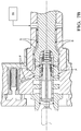
Fig. 4 . is a cross-sectional view of the camshaft phaser in accordance with the present invention taken through a lock pin of the camshaft phaser; -
Fig. 5A is an enlarged portion ofFig. 4 showing a valve spool of the camshaft phaser in a default position with a lock pin engaged with a lock pin seat; -
Fig. 5B is the view ofFig. 5A shown with reference numbers removed in order to clearly shown the path of travel of oil; -
Fig. 6A is the view ofFig. 5A now shown with the valve spool in a retard position now with the lock pin retracted from the lock pin seat; -
Fig. 6B is the view ofFig. 6A shown with reference numbers removed and arrows added in order to clearly show the path of travel of oil; -
Fig. 7A is the view ofFig. 5A now shown with the valve spool in a hold position now with the lock pin retracted from the lock pin seat; -
Fig. 7B is the view ofFig. 7A shown with reference numbers removed and arrows added in order to clearly show the path of travel of oil; -
Fig. 8A is the view ofFig. 5A now shown with the valve spool in an advance position now with the lock pin retracted from the lock pin seat; -
Fig. 8B is the view ofFig. 8A shown with reference numbers removed and arrows added in order to clearly show the path of travel of oil; -
Figs. 9 and 10 are isometric views of an insert of a valve spool of the camshaft phaser in accordance with the present invention; -
Figs. 11 and12 are isometric cross-sectional views of the valve spool and the insert of the camshaft phaser in accordance with the present invention; -
Fig. 13 is an isometric view of a supply check valve of the camshaft phaser in accordance with the present invention; and -
Fig. 14 is an elevation view of the valve spool. - In accordance with a preferred embodiment of this invention and referring to
Figs. 1-4 , aninternal combustion engine 10 is shown which includes acamshaft phaser 12.Internal combustion engine 10 also includes acamshaft 14 which is rotatable about acamshaft axis 16 based on rotational input from a crankshaft and belt (not shown) driven by a plurality of reciprocating pistons (also not shown). Ascamshaft 14 is rotated, it imparts valve lifting and closing motion to intake and/or exhaust valves (not shown) as is well known in the internal combustion engine art.Camshaft phaser 12 allows the timing between the crankshaft andcamshaft 14 to be varied. In this way, opening and closing of the intake and/or exhaust valves can be advanced or retarded in order to achieve desired engine performance. -
Camshaft phaser 12 generally includes astator 18 which acts and an input member, arotor 20 disposed coaxially withinstator 18 which acts as an output member, aback cover 22 closing off one end ofstator 18, afront cover 24 closing off the other end ofstator 18, alock pin 26, a camshaftphaser attachment bolt 28 for attachingcamshaft phaser 12 tocamshaft 14, and avalve spool 30. The various elements ofcamshaft phaser 12 will be described in greater detail in the paragraphs that follow. -
Stator 18 is generally cylindrical and includes a plurality ofradial chambers 31 defined by a plurality oflobes 32 extending radially inward. In the embodiment shown, there are fourlobes 32 defining fourradial chambers 31, however, it is to be understood that a different number oflobes 32 may be provided to defineradial chambers 31 equal in quantity to the number oflobes 32.Stator 18 may also include atoothed pulley 34 formed integrally therewith or otherwise fixed thereto.Pulley 34 is configured to be driven by a belt that is driven by the crankshaft ofinternal combustion engine 10. Alternatively,pulley 34 may be a sprocket driven by a chain or any other known drive member known for drivingcamshaft phaser 12 by the crankshaft. -
Rotor 20 includes acentral hub 36 with a plurality ofvanes 38 extending radially outward therefrom and a rotor central throughbore 40 extending axially therethrough. The number ofvanes 38 is equal to the number ofradial chambers 31 provided instator 18.Rotor 20 is coaxially disposed withinstator 18 such that eachvane 38 divides eachradial chamber 31 intoadvance chambers 42 andretard chambers 44. The radial tips oflobes 32 are mateable withcentral hub 36 in order to separateradial chambers 31 from each other. Each of the radial tips ofvanes 38 may include one of a plurality of wiper seals 46 to substantially sealadjacent advance chambers 42 andretard chambers 44 from each other. While not shown, each of the radial tips oflobes 32 may also include one of a plurality of wiper seals 46. - Back cover 22 is sealingly secured, using
cover bolts 48, to the axial end ofstator 18 that is proximal tocamshaft 14. Tightening ofcover bolts 48 prevents relative rotation betweenback cover 22 andstator 18. Aback cover seal 50, for example only, an O-ring, may be provided betweenback cover 22 andstator 18 in order to provide an oil-tight seal between the interface ofback cover 22 andstator 18. Back cover 22 includes a back cover central bore 52 extending coaxially therethrough. The end ofcamshaft 14 is received coaxially within back cover central bore 52 such thatcamshaft 14 is allowed to rotate relative to backcover 22. In an alternative arrangement,pulley 34 may be integrally formed or otherwise attached to backcover 22 rather thanstator 18. - Similarly,
front cover 24 is sealingly secured, usingcover bolts 48, to the axial end ofstator 18 that isopposite back cover 22. Afront cover seal 54, for example only, an O-ring, may be provided betweenfront cover 24 andstator 18 in order to provide an oil-tight seal between the interface offront cover 24 andstator 18. Coverbolts 48 pass throughback cover 22 andstator 18 and threadably engagefront cover 24, thereby clampingstator 18 betweenback cover 22 andfront cover 24 to prevent relative rotation betweenstator 18,back cover 22, andfront cover 24. In this way,advance chambers 42 andretard chambers 44 are defined axially betweenback cover 22 andfront cover 24. -
Camshaft phaser 12 is attached to camshaft 14 with camshaftphaser attachment bolt 28 which extends coaxially through rotor central throughbore 40 ofrotor 20 and threadably engagescamshaft 14, thereby by clampingrotor 20 securely tocamshaft 14. In this way, relative rotation betweenstator 18 androtor 20 results in a change is phase or timing between the crankshaft ofinternal combustion engine 10 andcamshaft 14. - Pressurized oil is selectively supplied to advance
chambers 42 from anoil source 55, which may be an oil pump ofinternal combustion engine 10, while oil is simultaneously vented fromretard chambers 44 in order to cause relative rotation betweenstator 18 androtor 20 which results in retarding the timing ofcamshaft 14 relative to the crankshaft ofinternal combustion engine 10. Conversely, pressurized oil is selectively supplied to retardchambers 44 fromoil source 55 while oil is simultaneously vented fromadvance chambers 42 in order to cause relative rotation betweenstator 18 androtor 20 which results in advancing the timing ofcamshaft 14 relative to the crankshaft ofinternal combustion engine 10.Rotor advance passages 56 may be provided inrotor 20 for supplying and venting oil to and fromadvance chambers 42 whilerotor retard passages 58 may be provided inrotor 20 for supplying and venting oil to and fromretard chambers 44. Supplying and venting oil to and fromadvance chambers 42 and to and fromretard chambers 44 is controlled byvalve spool 30, as will be described in detail later, such thatvalve spool 30 is coaxially disposed slidably within a valve bore 64 of camshaftphaser attachment bolt 28 where valve bore 64 is centered aboutcamshaft axis 16. -
Lock pin 26 selectively prevents relative rotation betweenstator 18 androtor 20 at a predetermined aligned position ofrotor 20 withinstator 18, which as shown, may be a full advance position, i.e.rotor 20 as far as possible withinstator 18 in the advance direction of rotation.Lock pin 26 is slidably disposed within a lock pin bore 66 formed in onevane 38 ofrotor 20. Alock pin seat 68 is provided infront cover 24 for selectively receivinglock pin 26 therewithin.Lock pin 26 andlock pin seat 68 are sized to substantially prevent rotation betweenstator 18 androtor 20 whenlock pin 26 is received withinlock pin seat 68. Whenlock pin 26 is not desired to be seated withinlock pin seat 68, pressurized oil is supplied to lock pin bore 66 through a rotorlock pin passage 72 formed inrotor 20, thereby urginglock pin 26 out oflock pin seat 68 and compressing alock pin spring 70. Conversely, whenlock pin 26 is desired to be seated withinlock pin seat 68, the pressurized oil is vented from lock pin bore 66 through rotorlock pin passage 72, thereby allowinglock pin spring 70 to urgelock pin 26 towardfront cover 24. In this way,lock pin 26 is seated withinlock pin seat 68 bylock pin spring 70 whenrotor 20 is positioned withinstator 18 to allow alignment oflock pin 26 withlock pin seat 68. Supplying and venting of pressurized oil to and fromlock pin 26 is controlled byvalve spool 30 as will be described later. - Camshaft
phaser attachment bolt 28 andvalve spool 30, which act together to function as a valve, will now be described in greater detail with continued reference toFigs. 1-4 and now with additional reference toFigs. 5A-14 . Camshaftphaser attachment bolt 28 includesbolt supply passages 74 which extend radially outward from valve bore 64 to the outside surface of camshaftphaser attachment bolt 28.Bolt supply passages 74 receive pressurized oil fromoil source 55 via an annularoil supply passage 78 formed radially between camshaftphaser attachment bolt 28 and a counter bore ofcamshaft 14 and also via radialcamshaft oil passages 80 ofcamshaft 14. The pressurized oil fromoil source 55 is used to 1) selectively supply oil to advancechambers 42, 2) selectively supply oil to retardchambers 44, and 3) selectively disengagelock pin 26 fromlock pin seat 68. Afilter 82 may circumferentially surround camshaftphaser attachment bolt 28 atbolt supply passages 74 in order to prevent foreign matter that may be present in the oil from reachingvalve spool 30. - Camshaft
phaser attachment bolt 28 also includes a bolt annularlock pin groove 84 on the outer periphery of camshaftphaser attachment bolt 28 and boltlock pin passages 86 extend radially outward from valve bore 64 to bolt annularlock pin groove 84. Bolt annularlock pin groove 84 is spaced axially apart frombolt supply passages 74 in a direction away fromcamshaft 14 and is aligned with a rotor annularlock pin groove 88 which extends radially outward from rotor central throughbore 40 such that rotorlock pin passage 72 extends from rotor annularlock pin groove 88 to lock pin bore 66. In this way, fluid communication is provided between valve bore 64 and lock pin bore 66. - Camshaft
phaser attachment bolt 28 also includes a boltannular advance groove 90 on the outer periphery of camshaftphaser attachment bolt 28 and bolt advancepassages 92 extend radially outward from valve bore 64 to boltannular advance groove 90. Boltannular advance groove 90 is spaced axially apart frombolt supply passages 74 and bolt annularlock pin groove 84 such that bolt annularlock pin groove 84 is axially betweenbolt supply passages 74 and boltannular advance groove 90. Boltannular advance groove 90 is aligned with a rotorannular advance groove 94 which extends radially outward from rotor central throughbore 40 such thatrotor advance passages 56 extend from rotorannular advance groove 94 to advancechambers 42. In this way, fluid communication is provided between valve bore 64 andadvance chambers 42. - Camshaft
phaser attachment bolt 28 also includes a boltannular retard groove 96 on the outer periphery of camshaftphaser attachment bolt 28 andbolt retard passages 98 extend radially outward from valve bore 64 to boltannular retard groove 96. Boltannular retard groove 96 is spaced axially apart from boltannular advance groove 90 such that boltannular advance groove 90 is axially between bolt annularlock pin groove 84 and boltannular retard groove 96. Boltannular retard groove 96 and is aligned with a rotorannular retard groove 100 which extends radially outward from rotor central throughbore 40 such thatrotor retard passages 58 extend from rotorannular retard groove 100 to retardchambers 44. In this way, fluid communication is provided between valve bore 64 andretard chambers 44. -
Valve spool 30 is moved axially alongcamshaft axis 16 within valve bore 64 of camshaftphaser attachment bolt 28 by anactuator 102 and avalve spring 104 to achieve desired operational states ofcamshaft phaser 12 by opening and closingbolt supply passages 74, boltlock pin passages 86,bolt advance passages 92, and boltretard passages 98 as will now be described.Valve spool 30 includes a valve spool bore 106 extending axially thereinto from the end ofvalve spool 30 that is proximal tocamshaft 14. Aninsert 108 is disposed within valve spool bore 106 such thatinsert 108 defines a phasing volume 110 and a venting volume 112 (best visible inFig. 11 ) such that phasing volume 110 is substantially fluidly segregated from ventingvolume 112, i.e. phasing volume 110 does not communicate with ventingvolume 112. By way of non-limiting example only, insert 108 may be net-formed by plastic injection molding and may be easily inserted within valve spool bore 106 from the end of valve spool bore 106 that is proximal tovalve spring 104 prior tovalve spool 30 being inserted into valve bore 64 of camshaftphaser attachment bolt 28. In this way, phasing volume 110 and ventingvolume 112 are easily and economically formed. -
Valve spool 30 also includes asupply land 114 which is sized to fit within valve bore 64 in a close sliding relationship such that oil is substantially prevented from passing between the interface betweensupply land 114 and valve bore 64 while allowingvalve spool 30 to be displaced axially within valve bore 64 substantially uninhibited. -
Valve spool 30 also includes a spoolannular supply groove 116 that is axially adjacent to supplyland 114. Aspool supply passage 118a and aspool supply passage 118b are provided such thatspool supply passage 118a andspool supply passage 118b each extend radially inward from spoolannular supply groove 116 to phasing volume 110 within valve spool bore 106 and such thatspool supply passage 118a is diametrically opposed tospool supply passage 118b.Spool supply passage 118a andspool supply passage 118b are both preferably slots which extend in a circumferential direction aboutcamshaft axis 16 further than in the direction ofcamshaft axis 16. Asupply check valve 120 is disposed within phasing volume 110, as will be described in greater detail later, in order to allow oil to enter phasing volume 110 fromspool supply passage 118a and fromspool supply passage 118b while substantially preventing oil from exiting phasing volume 110 tospool supply passage 118a and tospool supply passage 118b. -
Valve spool 30 also includes alock pin land 122 that is axially adjacent to spoolannular supply groove 116.Lock pin land 122 is sized to fit within valve bore 64 in a close sliding relationship such that oil is substantially prevented from passing between the interface betweenlock pin land 122 and valve bore 64 while allowingvalve spool 30 to be displaced axially within valve bore 64 substantially uninhibited.Lock pin land 122 is axially divided by an spool annularlock pin groove 124 such that a spool lock pin passage 126 (best visible inFig. 14 ) extends radially inward from spool annularlock pin groove 124 to ventingvolume 112 within valve spool bore 106, thereby providing fluid communication between spool annularlock pin groove 124 and ventingvolume 112. -
Valve spool 30 also includes a spoolannular advance groove 128 that is axially adjacent to lockpin land 122. Aspool advance passage 130 is provided which extends radially inward from spoolannular advance groove 128 to phasing volume 110 within valve spool bore 106 in order to provide fluid communication between spoolannular advance groove 128 and phasing volume 110.Spool advance passage 130 is preferably a slot which extends in a circumferential direction aboutcamshaft axis 16 further than in the direction ofcamshaft axis 16 and preferably extends circumferentially about half of the way around spoolannular advance groove 128. -
Valve spool 30 also includes anadvance land 131 that is axially adjacent to spoolannular advance groove 128.Advance land 131 is sized to fit within valve bore 64 in a close sliding relationship such that oil is substantially prevented from passing between the interface betweenadvance land 131 and valve bore 64 while allowingvalve spool 30 to be displaced axially within valve bore 64 substantially uninhibited. -
Valve spool 30 also includes a spoolannular vent groove 132 that is axially adjacent to advanceland 131. A spool vent passage 134 (best visible inFigs. 12 and14 ) is provided such thatspool vent passage 134 extends radially inward from spoolannular vent groove 132 to phasing volume 110 within valve spool bore 106.Spool vent passage 134 is preferably a slot which extends in a circumferential direction aboutcamshaft axis 16 further than in the direction ofcamshaft axis 16 and preferably extends circumferentially about half of the way around spoolannular vent groove 132. -
Valve spool 30 also includes aretard land 138 that is axially adjacent to spoolannular vent groove 132.Retard land 138 is sized to fit within valve bore 64 in a close sliding relationship such that oil is substantially prevented from passing between the interface betweenretard land 138 and valve bore 64 while allowingvalve spool 30 to be displaced axially within valve bore 64 substantially uninhibited. -
Valve spool 30 also includes a spoolannular retard groove 140 that is axially adjacent to retardland 138. Aspool retard passage 142 is provided such thatspool retard passage 142 extends radially inward from spoolannular retard groove 140 to phasing volume 110 within valve spool bore 106 in order to provide fluid communication between spoolannular retard groove 140 and phasing volume 110.Spool retard passage 142 is preferably a slot which extends in a circumferential direction aboutcamshaft axis 16 further than in the direction ofcamshaft axis 16 and preferably extends circumferentially about half of the way around spoolannular retard groove 140. -
Valve spool 30 also includes anend land 144 that is axially adjacent to spoolannular retard groove 140.End land 144 is sized to fit within valve bore 64 in a close sliding relationship such that oil is substantially prevented from passing between the interface betweenend land 144 and valve bore 64 while allowingvalve spool 30 to be displaced axially within valve bore 64 substantially uninhibited. -
Valve spool 30 also includes ventpassages 146 which extend radially outward from ventingvolume 112, thereby allowing oil within ventingvolume 112 to be vented to valve bore 64 and out ofcamshaft phaser 12 where it may be drained back tooil source 55. Alternatively, a passage could be formed in camshaftphaser attachment bolt 28 which extends from valve bore 64 to a drain passage incamshaft 14 in order to vent oil within ventingvolume 112 where it may be drained back tooil source 55. -
Actuator 102 may be a solenoid actuator that is selectively energized with an electric current of varying magnitude in order to positionvalve spool 30 within valve bore 64 at desired axial positions, thereby controlling oil flow to achieve desired operation ofcamshaft phaser 12. In a default position, when no electric current is supplied toactuator 102 as shown inFigs. 5A and5B ,valve spring 104 urgesvalve spool 30 in a direction towardactuator 102 untilvalve spool 30 axially abuts afirst stop member 148, which may be, by way of non-limiting example only, a snap ring within a snap ring groove extending radially outward from valve bore 64. In the default position,supply land 114 is positioned to provide fluid communication betweenbolt supply passages 74 and spoolannular supply groove 116, thereby allowing pressurized oil to be supplied to phasing volume 110 throughspool supply passages supply check valve 120 fromoil source 55. Also in the default position,lock pin land 122 is positioned to align spool annularlock pin groove 124 with boltlock pin passages 86, thereby allowing oil to be vented from lock pin bore 66 via rotorlock pin passage 72, rotor annularlock pin groove 88, bolt annularlock pin groove 84, boltlock pin passages 86, spool annularlock pin groove 124, spoollock pin passage 126, ventingvolume 112, and ventpassages 146 and consequently allowinglock pin spring 70 to urgelock pin 26 towardfront cover 24. In the default position,lock pin land 122 also blocks fluid communication between boltlock pin passages 86 and phasing volume 110. Also in the default position, advanceland 131 is positioned to block fluid communication betweenbolt advance passages 92 and spoolannular vent groove 132 while simultaneously permitting fluid communication betweenbolt advance passages 92 and phasing volume 110 via spoolannular advance groove 128 andspool advance passage 130. Also in the default position, retardland 138 is positioned to block fluid communication between phasing volume 110 and boltretard passages 98 while simultaneously permitting fluid communication betweenbolt retard passages 98 and ventingvolume 112 via spoolannular vent groove 132, andspool vent passage 134. In this way, pressurized oil that is supplied to phasing volume 110 fromoil source 55 is supplied to advancechambers 42 viaspool advance passage 130, spoolannular advance groove 128,bolt advance passages 92, boltannular advance groove 90, rotorannular advance groove 94, androtor advance passages 56 while oil is simultaneously vented fromretard chambers 44 viarotor retard passages 58, rotorannular retard groove 100, boltannular retard groove 96,bolt retard passages 98, spoolannular vent groove 132,spool vent passage 134, ventingvolume 112, and ventpassages 146, thereby causingrotor 20 to rotate relative tostator 18 to cause a retard in timing ofcamshaft 14 relative to the crankshaft, and whenlock pin 26 is aligned withlock pin seat 68,lock pin spring 70 urges lockpin 26 intolock pin seat 68 to retainrotor 20 in the predetermined aligned position withstator 18. InFig. 5B , the reference numbers have been removed for clarity and arrows representing the path of travel of the oil have been included where arrows S represent oil fromoil source 55 that is supplied to advancechambers 42 and arrows V represent vented oil from lock pin bore 66 and fromretard chambers 44. It should be noted thatFig. 5B showssupply check valve 120 being open, butsupply check valve 120 may also be closed if a torque reversal acting oncamshaft 14 causes the pressure within phasing volume 110 to be greater than the pressure of oil fromoil source 55. - In a retard position, when an electric current of a first magnitude is supplied to
actuator 102 as shown inFigs. 6A and6B ,actuator 102 urgesvalve spool 30 in a direction towardvalve spring 104 thereby causingvalve spring 104 to be compressed slightly. In the retard position,supply land 114 is positioned to provide fluid communication betweenbolt supply passages 74 and spoolannular supply groove 116, thereby allowing pressurized oil to be supplied to phasing volume 110 throughspool supply passages supply check valve 120 fromoil source 55. Also in the retard position,lock pin land 122 is positioned to prevent fluid communication between boltlock pin passages 86 and spool annularlock pin groove 124, thereby preventing oil from being vented from lock pin bore 66. Also in the retard position,lock pin land 122 is positioned to permit fluid communication between boltlock pin passages 86 and phasing volume 110, thereby allowing pressurized oil to be supplied to lock pin bore 66 viaspool advance passage 130, spoolannular advance groove 128, boltlock pin passages 86, bolt annularlock pin groove 84, rotor annularlock pin groove 88, and rotorlock pin passage 72, and as a result,lock pin 26 compresses lockpin spring 70 andlock pin 26 is retracted fromlock pin seat 68. Also in the retard position, advanceland 131 is positioned to block fluid communication betweenbolt advance passages 92 and spoolannular vent groove 132 while simultaneously permitting fluid communication betweenbolt advance passages 92 and phasing volume 110 via spoolannular advance groove 128 andspool advance passage 130. Also in the retard position, retardland 138 is positioned to block fluid communication between phasing volume 110 and boltretard passages 98 while simultaneously permitting fluid communication betweenbolt retard passages 98 and ventingvolume 112 via spoolannular vent groove 132, andspool vent passage 134. In this way, pressurized oil that is supplied to phasing volume 110 fromoil source 55 is supplied to advancechambers 42 viaspool advance passage 130, spoolannular advance groove 128,bolt advance passages 92, boltannular advance groove 90, rotorannular advance groove 94, androtor advance passages 56 while oil is simultaneously vented fromretard chambers 44 viarotor retard passages 58, rotorannular retard groove 100, boltannular retard groove 96,bolt retard passages 98, spoolannular vent groove 132,spool vent passage 134, ventingvolume 112, and ventpassages 146, thereby causingrotor 20 to rotate relative tostator 18 to cause a retard in timing ofcamshaft 14 relative to the crankshaft. InFig. 6B , the reference numbers have been removed for clarity and arrows representing the path of travel of the oil have been included where arrows S represent oil fromoil source 55 that is supplied to advancechambers 42 and to lock pin bore 66 and arrows V represent vented oil fromretard chambers 44. It should be noted thatFig. 6B showssupply check valve 120 being open, butsupply check valve 120 may also be closed if a torque reversal acting oncamshaft 14 causes the pressure within phasing volume 110 to be greater than the pressure of oil fromoil source 55. - In a hold position, when an electric current of a second magnitude is supplied to
actuator 102 as shown inFigs. 7A and7B ,actuator 102 urgesvalve spool 30 in a direction towardvalve spring 104 thereby causingvalve spring 104 to be compressed slightly more than in the retard position. In the hold position,supply land 114 is positioned to provide fluid communication betweenbolt supply passages 74 and spoolannular supply groove 116, thereby allowing pressurized oil to be supplied to phasing volume 110 throughspool supply passages supply check valve 120 fromoil source 55. Also in the hold position,lock pin land 122 is positioned to prevent fluid communication between boltlock pin passages 86 and spool annularlock pin groove 124, thereby preventing oil from being vented from lock pin bore 66. Also in the hold position,lock pin land 122 is positioned to permit fluid communication between boltlock pin passages 86 and phasing volume 110, thereby allowing pressurized oil to be supplied to lock pin bore 66 viaspool advance passage 130, spoolannular advance groove 128, boltlock pin passages 86, bolt annularlock pin groove 84, rotor annularlock pin groove 88, and rotorlock pin passage 72, and as a result,lock pin 26 compresses lockpin spring 70 andlock pin 26 is retracted fromlock pin seat 68. Also in the hold position, advanceland 131 is positioned to block fluid communication betweenbolt advance passages 92 and spoolannular vent groove 132 while simultaneously permitting restricted communication betweenbolt advance passages 92 and phasing volume 110 via spoolannular advance groove 128 andspool advance passage 130. Also in the hold position, retardland 138 is positioned to block fluid communication betweenbolt retard passages 98 and spoolannular vent groove 132 while simultaneously permitting restricted fluid communication betweenbolt retard passages 98 and phasing volume 110 via spoolannular retard groove 140 andspool retard passage 142. By providing restricted fluid communication betweenbolt advance passages 92 and phasing volume 110 and betweenbolt retard passages 98 and phasing volume 110 while simultaneously blocking fluid communication betweenbolt advance passages 92 and spoolannular vent groove 132 and betweenbolt retard passages 98 and spoolannular vent groove 132, the rotational position ofrotor 20 andstator 18 is substantially maintained in the hold position. InFig. 7B , the reference numbers have been removed for clarity and arrows representing the path of travel of the oil have been included where arrows S represent oil fromoil source 55 which retractslock pin 26 fromlock pin seat 68 and which is supplied restrictingly to advancechambers 42 andretard chambers 44. It should be noted thatFig. 7B showssupply check valve 120 being open, but may typically remain closed unlesslock pin 26 is in the process of being retracted fromlock pin seat 68. - In an advance position, when an electric current of a third magnitude is supplied to
actuator 102 as shown inFigs. 8A and8B ,actuator 102 urgesvalve spool 30 in a direction towardvalve spring 104 thereby causingvalve spring 104 to be compressed slightly more than in the hold position untilvalve spool 30 abuts asecond stop member 150, which may be, by way of non-limiting example only, a shoulder formed in valve bore 64. In the advance position,supply land 114 is positioned to provide fluid communication betweenbolt supply passages 74 and spoolannular supply groove 116, thereby allowing pressurized oil to be supplied to phasing volume 110 throughspool supply passages supply check valve 120 fromoil source 55. Also in the advance position,lock pin land 122 is positioned to prevent fluid communication between boltlock pin passages 86 and spool annularlock pin groove 124, thereby preventing oil from being vented from lock pin bore 66. Also in the advance position,lock pin land 122 is positioned to permit fluid communication between boltlock pin passages 86 and phasing volume 110, thereby allowing pressurized oil to be supplied to lock pin bore 66 viaspool advance passage 130, spoolannular advance groove 128, boltlock pin passages 86, bolt annularlock pin groove 84, rotor annularlock pin groove 88, and rotorlock pin passage 72, and as a result,lock pin 26 compresses lockpin spring 70 andlock pin 26 is retracted fromlock pin seat 68. Also in the advance position, advanceland 131 is positioned to block fluid communication between phasing volume 110 and boltadvance passages 92 while simultaneously permitting fluid communication betweenbolt advance passages 92 and ventingvolume 112 via spoolannular vent groove 132, andspool vent passage 134. Also in the advance position, retardland 138 is positioned to block fluid communication betweenbolt retard passages 98 and spoolannular vent groove 132 while simultaneously permitting fluid communication betweenbolt retard passages 98 and phasing volume 110 via spoolannular retard groove 140 andspool retard passage 142. In this way, pressurized oil that is supplied to phasing volume 110 fromoil source 55 is supplied to retardchambers 44 viaspool retard passage 142, spoolannular retard groove 140,bolt retard passages 98, boltannular retard groove 96, rotorannular retard groove 100, androtor retard passages 58 while oil is simultaneously vented fromadvance chambers 42 viarotor advance passages 56, rotorannular advance groove 94,bolt advance passages 92, spoolannular vent groove 132,spool vent passage 134, ventingvolume 112, and ventpassages 146, thereby causingrotor 20 to rotate relative tostator 18 to cause an advance in timing ofcamshaft 14 relative to the crankshaft. InFig. 8B , the reference numbers have been removed for clarity and arrows representing the path of travel of the oil have been included where arrows S represent oil fromoil source 55 that is supplied to retardchambers 44 and lock pin bore 66 and arrows V represent vented oil fromadvance chambers 42. It should be noted thatFig. 8B showssupply check valve 120 being open, butsupply check valve 120 may also be closed if a torque reversal acting oncamshaft 14 causes the pressure within phasing volume 110 to be greater than the pressure of oil fromoil source 55. -
Insert 108 will now be describe with particular reference toFigs. 9-12 whereFigs. 9 and 10 are isometric views ofinsert 108 andFigs. 11 and12 are isometric axial cross-sectional views ofvalve spool 30 andinsert 108.Insert 108 is defined by an insert first sidewall 152 which extends axially within valve spool bore 106 and is also defined by an insert second sidewall 153 which extends axially within valve spool bore 106 such that insert first sidewall 152 and insert second sidewall 153 occupy distinct axial portions of valve spool bore 106. Insert first sidewall 152 is positioned to a side of valve spool bore 106 such that a first side 152a of insert first sidewall 152 faces toward and is contoured to mate sealingly with valve spool bore 106 while a second side 152b of insert first sidewall 152 which opposes first side 152a defines a portion of phasing volume 110 together with valve spool bore 106. Insert first sidewall 152 includes insert first sidewall recesses 152c which extend into second side 152b in order to accommodate opening ofsupply check valve 120 as will be described in greater detail later. Insert second sidewall 153 bifurcates valve spool bore 106 such that a first side 153a defines a portion of phasing volume 110 together with valve spool bore 106 and a second side 153b which opposes first side 153a defines a portion of ventingvolume 112 together with valve spool bore 106.Insert 108 is also defined by an insertfirst end wall 154 which traverses valve spool bore 106 in a direction substantially perpendicular tocamshaft axis 16 such that insertfirst end wall 154 is contoured to sealing mate with valve spool bore 106.Insert 108 is also defined by an insertsecond end wall 156 which joins insert first sidewall 152 to insert second sidewall 153 such that insertsecond end wall 156 extends axially between insert first sidewall 152 and second sidewall 153 and such that insert first sidewall 152 joins insertfirst end wall 154 to insertsecond end wall 156. Insertsecond end wall 156 is contoured to mate sealingly with valve spool bore 106.Insert 108 is also defined by an insertthird end wall 157 which extends from insert second sidewall 153 to valve spool bore 106 such that insertthird end wall 157 is contoured to mate sealingly with valve spool bore 106. In this way, a portion of phasing volume 110 is defined axially between insertfirst end wall 154 and insertsecond end wall 156 and a portion of phasing volume 110 is defined axially between insertfirst end wall 154 and insertthird end wall 157.Insert 108 may include aninsert rib 158 which extends axially from insertfirst end wall 154 to insertsecond end wall 156 and from insertfirst end wall 154 to insertthird end wall 157 such that insertrib 158 extends from insert first sidewall 152 toward valve spool bore 106 and from insert second sidewall 153, thereby bifurcating phasing volume 110 intofirst phasing volume 110a andsecond phasing volume 110b.Insert rib 158 provides support to insertfirst end wall 154, insertsecond end wall 156, and insertthird end wall 157 in order to resist force created during times when phasing volume 110 is exposed to high pressure.Insert rib 158 may also include an insertrib positioning notch 158a which positionssupply check valve 120 as will be described in greater detail later. Insertrib positioning notch 158a extends into the edge ofinsert rib 158 which faces toward valve spool bore - 106 such that insert
rib positioning notch 158a provides fluid communication betweenfirst phasing volume 110a andsecond phasing volume 110b, thereby preventing a pressure differential betweenfirst phasing volume 110a andsecond phasing volume 110b. Aninsert spring wall 160 extends axially from insertfirst end wall 154 in a direction that is opposite of insert first sidewall 152 such that insertspring wall 160 is hollow in order to receive a portion ofvalve spring 104 therein. In this way, one end ofvalve spring 104 mates with insertfirst end wall 154 and is maintained in a centered relationship aboutcamshaft axis 16 byinsert spring wall 160. In order to provide proper orientation ofinsert 108 within valve spool bore 106, insertspring wall 160 may include analignment tab 160a which is received within a complementary spool alignment notch (not shown) invalve spool 30. Aninsert slot 162 extends axially alonginsert 108 such thatinsert slot 162 extends alonginsert spring wall 160, insertfirst end wall 154, first side 152a of insert first sidewall 152, and insertsecond end wall 156. In this way, a portion of ventingvolume 112 is defined betweeninsert slot 162 and valve spool bore 106 while, as described previously, a portion of ventingvolume 112 is defined between insert second sidewall 153 and valve spool bore 106. It should be noted that since insert second sidewall 153 bifurcates valve spool bore 106, the portions of phasing volume 110 and ventingvolume 112 have substantially the same cross-sectional areas when sectioned by a plane that is perpendicular tocamshaft axis 16. As used herein, the cross-sectional areas of phasing volume 110 and ventingvolume 112 may differ by about 10% or less while still being considered to be substantially the same. It should also be noted thatspool supply passages camshaft axis 16 with the portion of phasing volume 110 that is defined by insert first sidewall 152, thatspool advance passage 130 is aligned alongcamshaft axis 16 with the portion of phasing volume 110 that is defined by insert first sidewall 152, thatspool vent passage 134 is aligned alongcamshaft axis 16 with the portion of ventingvolume 112 that is defined by insert second sidewall 153, and thatspool retard passage 142 is aligned alongcamshaft axis 16 with the portion of ventingvolume 112 that is defined by insert second sidewall 153. -
Supply check valve 120 will now be described with particular reference toFig. 13 .Supply check valve 120 includes a firstcheck valve member 164 and a secondcheck valve member 166 such that firstcheck valve member 164 is located withinfirst phasing volume 110a and secondcheck valve member 166 is located withinsecond phasing volume 110b and such that firstcheck valve member 164 is diametrically opposed to secondcheck valve member 166 within valve spool bore 106. Firstcheck valve member 164 and secondcheck valve member 166 are each arcuate in shape in order to match the curvature of valve spool bore 106 and are sized to selectively block respectivespool supply passages Supply check valve 120 also includes a biasing section 168 which joins firstcheck valve member 164 and secondcheck valve member 166. Biasing section 168 is resilient and compliant in order to bias firstcheck valve member 164 and secondcheck valve member 166 into contact with valve spool bore 106 while allowing firstcheck valve member 164 and secondcheck valve member 166 to be displaced inward under operating conditions as described previously which require flow into phasing volume 110 throughspool supply passages check valve member 164 withinfirst phasing volume 110a, a biasing section second leg 168b which extends axially from secondcheck valve member 166 withinsecond phasing volume 110b, and a biasing section bridge 168c which joins biasing section first leg 168a and biasing section second leg 168b such that biasing section bridge 168c is axially spaced from firstcheck valve member 164 and from secondcheck valve member 166. Biasing section bridge 168c passes betweenfirst phasing volume 110a andsecond phasing volume 110b through insertrib positioning notch 158a. Biasing section bridge 168c and insertrib positioning notch 158a are sized to maintain the axial position ofsupply check valve 120 within phasing volume 110 to ensure that firstcheck valve member 164 and secondcheck valve member 166 are properly positioned to block respectivespool supply passages check valve member 164 and secondcheck valve member 166 are biased into contact with valve spool bore 106. It should be noted that when firstcheck valve member 164 and secondcheck valve member 166 are opened by oil pressure, firstcheck valve member 164 and secondcheck valve member 166 are each received within a respective insertfirst sidewall recess 152c. As shown,supply check valve 120 may be a simple one-piece device that is made of formed sheet metal. - While
camshaft phaser 12 has been described as defaulting to full advance, it should now be understood thatcamshaft phaser 12 may alternatively default to full retard by simply rearranging oil passages. Similarly, while full advance has been described as full counterclockwise rotation ofrotor 20 withinstator 18 as shown inFig. 2 , it should also now be understood that full advance may alternatively be full clockwise rotation ofrotor 20 withinstator 18 depending on whethercamshaft phaser 12 is mounted to the front of internal combustion engine 10 (shown in the figures) or to the rear ofinternal combustion engine 10. - While camshaft
phaser attachment bolt 28 has been described herein as including grooves on the outer periphery thereof which are aligned with corresponding grooves formed in rotor central throughbore 40 ofrotor 20, it should now be understood that the grooves on camshaftphaser attachment bolt 28 could be omitted and the grooves formed in rotor central throughbore 40 could be used to serve the same function. Similarly, the grooves formed in rotor central throughbore 40 could be omitted and the grooves on camshaftphaser attachment bolt 28 could be used to serve the same function. -
Valve spool 30,insert 108, andsupply check valve 120 as described herein allow for simplified construction ofcamshaft phaser 12 compared to the prior art. Furthermore, supplying oil to lockpin 26 from phasing volume 110 eliminates the need for an additional groove invalve spool 30 and an additional groove between camshaftphaser attachment bolt 28 and rotor central through bore 40 to create a separate supply forlock pin 26. Moreover, insert 108 accommodatesspool supply passages spool supply passages insert 108 is that by insert second sidewall 153 bifurcating valve spool bore 106 and byspool vent passage 134 being aligned alongcamshaft axis 16 with the portion of ventingvolume 112 that is defined by insert second sidewall 153, the flow of oil being vented can match the flow of oil being supplied, thereby increasing the phasing rate ofcamshaft phaser 12. - While this invention has been described in terms of preferred embodiments thereof, it is not intended to be so limited, but rather only to the extent set forth in the claims that follow.
Claims (15)
- A camshaft phaser (12) for use with an internal combustion engine (10) for controllably varying the phase relationship between a crankshaft and a camshaft (14) in said internal combustion engine (10), said camshaft phaser (12) comprising:an input member (18) connectable to said crankshaft of said internal combustion engine (10) to provide a fixed ratio of rotation between said input member (18) and said crankshaft;an output member (20) connectable to said camshaft (14) of said internal combustion engine (10) and defining an advance chamber (42) and a retard chamber (44) with said input member (18); anda valve spool (30) moveable along an axis (16) between an advance position and a retard position and having a valve spool bore (106) with a phasing volume (110) and a venting volume (112) defined within said valve spool bore (106) such that said phasing volume (110) is fluidly segregated from said venting volume (112), said valve spool (30) having a first spool supply passage (118a) and a second spool supply passage (118a) which is diametrically opposed to said first spool supply passage (118a) such that said first spool supply passage (118a) and said second spool supply passage (118a) each provide a path for pressurized oil to be supplied to said phasing volume (110) from an oil source (55);wherein oil is supplied to said advance chamber (42) from said phasing volume (110) and oil is vented from said retard chamber (44) to said venting volume (112) in order to retard the timing of said camshaft (14) relative to said crankshaft; andwherein oil is supplied to said retard chamber (44) from said phasing volume (110) and oil is vented from said advance chamber (42) to said venting volume (112) in order to advance the timing of said camshaft (14) relative to said crankshaft.
- A camshaft phaser (12) as in claim 1 further comprising a supply check valve (120) within said valve spool bore (106) which allows oil to flow to said phasing volume (110) from said oil source (55) while preventing oil from flowing from said phasing volume (110) to said oil source (55).
- A camshaft phaser (12) as in any one of claims 1 to 2 further comprising a camshaft phaser attachment bolt (28) for attaching said camshaft phaser (12) to said camshaft (14) wherein said camshaft phaser attachment bolt (28) includes a valve bore (64) within which said valve spool (30) is slidably disposed.
- A camshaft phaser (12) as in any one of claims 2 to 3 wherein said supply check valve (120) is disposed within said phasing volume (110).
- A camshaft phaser (12) as in any one of claims 2 to 4 wherein said supply check valve (120) comprises:a first check valve member (164) which allows oil to enter said phasing volume (110) through said first spool supply passage (118a) and which prevents oil from exiting said phasing volume (110) through said first spool supply passage (118a); anda second check valve member (166) diametrically opposed to said first check valve member (164) which allows oil to enter said phasing volume (110) through said second spool supply passage (118a) and which prevents oil from exiting said phasing volume (110) through said second spool supply passage (118a).
- A camshaft phaser (12) as in any one of claims 2 to 5 wherein said phasing volume (110) and said venting volume (112) are defined by an insert (108) that is disposed within said valve spool bore (106).
- A camshaft phaser (12) as in claim 6 wherein said insert (108) comprises:an insert first end wall (154);an insert second end wall (156) spaced axially from said insert first end wall (154);an insert third end wall (157) spaced axially from said insert second end wall (156) such that said insert second end wall (156) is axially between said insert first end wall (154) and said insert second end wall (156);an insert first sidewall (152) between said insert first end wall (154) and said insert second end wall (156) such that that said insert first sidewall (152) connects said insert first end wall (154) to said insert second end wall (156); andan insert second sidewall (153) between said insert second end wall (156) and said insert third end wall (157) such that said insert second sidewall (153) connects said insert second end wall (156) to said insert third end wall (157) and such that said insert second sidewall (153) is offset relative to said insert first sidewall (152) in a direction perpendicular to said axis (16).
- A camshaft phaser (12) as in claim 7 wherein said phasing volume (110) is defined axially between said insert first end wall (154) and said insert second end wall (156) and is also defined axially between said insert second end wall (156) and said insert third end wall (157).
- A camshaft phaser (12) as in any one of claims 7 to 8 wherein said first spool supply passage (118a) and said second spool supply passage (118a) are aligned with said insert first sidewall (152) along said axis (16).
- A camshaft phaser (12) as in any one of claims 7 to 9 wherein:said valve spool (30) has a spool advance passage (130) which provides a path for pressurized oil to be supplied to said advance chamber (42) from said phasing volume (110) in order to retard the timing of said camshaft (14) relative to said crankshaft, said spool advance passage (130) being aligned with said insert first sidewall (152) along said axis (16);said valve spool (30) has a spool vent passage (134) which provides a path for oil to vent from said retard chamber (44) to said venting volume (112) in order to retard the timing of said camshaft (14) relative to said crankshaft and which also provides a path for oil to vent from said advance chamber (42) to said venting volume (112) in order to advance the timing of said camshaft (14) relative to said crankshaft, said spool vent passage (134) being aligned with said insert second sidewall (153) along said axis (16); andsaid valve spool (30) has a spool retard passage (142) which provides a path for pressurized to be supplied to said retard chamber (44) from said phasing volume (110) in order to advance the timing of said camshaft (14) relative to said crankshaft, said spool retard passage (142) being aligned with said insert second sidewall (153) along said axis (16).
- A camshaft phaser (12) as in any one of claims 7 to 10 wherein said insert second sidewall (153) bifurcates said valve spool bore (106).
- A camshaft phaser (12) as in any one of claims 7 to 11 wherein said insert (108) further comprises an insert rib (158) which connects said insert first end wall (154) to said insert second end wall (156) and which also connects said insert first end wall (154) to said insert third end wall (157), said insert rib (158) extending from said insert first sidewall (152) into said phasing volume (110) and also extending from said insert second sidewall (153) into said phasing volume (110), thereby bifurcating said phasing volume (110) into a first phasing volume (110a) and a second phasing volume (110b).
- A camshaft phaser (12) as in claim 12 wherein said supply check valve (120) comprises:the first check valve member (164) within said first phasing volume (110a) which allows oil to enter said phasing volume (110) through said first spool supply passage (118a) and which prevents oil from exiting said phasing volume (110) through said first spool supply passage (118a); andthe second check valve member (166) within said second phasing volume (110b) and diametrically opposed to said first check valve member (164) such that said second check valve member (166) allows oil to enter said phasing volume (110) through said second spool supply passage (118a) and such that said second check valve member (166) prevents oil from exiting said phasing volume (110) through said second spool supply passage (118a).
- A camshaft phaser (12) as in any one of claims 7 to 13 wherein said insert first sidewall (152) has insert first sidewall recesses (152c) which accommodate said first check valve member (164) and said second check valve member (166) when said first check valve member (164) allows oil to flow into said phasing volume (110) and when said second check valve member (166) allows oil to flow into said phasing volume (110).
- A camshaft phaser (12) as in claim 7 wherein said supply check valve (120) comprises:the first check valve member (164) within said phasing volume (110) which allows oil to enter said phasing volume (110) through said first spool supply passage (118a) and which prevents oil from exiting said phasing volume (110) through said first spool supply passage (118a);the second check valve member (166) within said phasing volume (110) and diametrically opposed to said first check valve member (164) such that said second check valve member (166) allows oil to enter said phasing volume (110) through said second spool supply passage (118a) and such that said second check valve member (166) prevents oil from exiting said phasing volume (110) through said second spool supply passage (118a); anda biasing section (168) which joins said first check valve member (164) and said second check valve member (166), said biasing section (168) being resilient and compliant such that said biasing section (168) biases said first check valve member (164) to block said first spool supply passage (118a) and such that said biasing section (168) biases said second check valve member (166) to block said second spool supply passage (118a).
Applications Claiming Priority (1)
| Application Number | Priority Date | Filing Date | Title |
|---|---|---|---|
| US14/936,888 US10082054B2 (en) | 2015-11-10 | 2015-11-10 | Camshaft phaser |
Publications (1)
| Publication Number | Publication Date |
|---|---|
| EP3168515A1 true EP3168515A1 (en) | 2017-05-17 |
Family
ID=57281111
Family Applications (1)
| Application Number | Title | Priority Date | Filing Date |
|---|---|---|---|
| EP16198051.1A Withdrawn EP3168515A1 (en) | 2015-11-10 | 2016-11-09 | Camshaft phaser |
Country Status (2)
| Country | Link |
|---|---|
| US (1) | US10082054B2 (en) |
| EP (1) | EP3168515A1 (en) |
Cited By (1)
| Publication number | Priority date | Publication date | Assignee | Title |
|---|---|---|---|---|
| DE102017201743B4 (en) | 2016-02-05 | 2022-12-08 | Delphi Powertrain Systems Korea Ltd. | Control valve for a valve timing adjuster for an internal combustion engine |
Families Citing this family (4)
| Publication number | Priority date | Publication date | Assignee | Title |
|---|---|---|---|---|
| KR101679020B1 (en) | 2015-12-23 | 2016-12-29 | 현대자동차주식회사 | Locking structure of valve timing adjusting device for internal combustion engine |
| KR101679016B1 (en) | 2015-12-23 | 2017-01-02 | 현대자동차주식회사 | Apparatus of adjusting valve timing for internal combustion engine |
| US11174760B2 (en) * | 2018-12-11 | 2021-11-16 | Delphi Technologies Ip Limited | Camshaft phaser |
| US10662828B1 (en) | 2018-12-11 | 2020-05-26 | Delphi Technologies Ip Limited | Camshaft phaser |
Citations (5)
| Publication number | Priority date | Publication date | Assignee | Title |
|---|---|---|---|---|
| US6772721B1 (en) | 2003-06-11 | 2004-08-10 | Borgwarner Inc. | Torsional assist cam phaser for cam in block engines |
| EP1447602A1 (en) * | 2003-02-17 | 2004-08-18 | Delphi Technologies, Inc. | Oil flow control valve for a cam phaser |
| US20060225791A1 (en) * | 2005-03-18 | 2006-10-12 | Hydraulik-Ring Gmbh | Valve with check valve |
| US20080236529A1 (en) * | 2005-09-01 | 2008-10-02 | Schaeffler Kg | Control Valve for a Device for Changing the Control Times of an Internal Combustion Engine |
| WO2014006056A1 (en) * | 2012-07-06 | 2014-01-09 | Hilite Germany Gmbh | Oscillating motor adjuster with a hydraulic valve |
Family Cites Families (14)
| Publication number | Priority date | Publication date | Assignee | Title |
|---|---|---|---|---|
| DE10205415A1 (en) | 2002-02-09 | 2003-08-28 | Porsche Ag | Device for the relative rotation angle adjustment of a camshaft of an internal combustion engine to a drive wheel |
| US6814038B2 (en) | 2002-09-19 | 2004-11-09 | Borgwarner, Inc. | Spool valve controlled VCT locking pin release mechanism |
| US7137371B2 (en) | 2003-02-07 | 2006-11-21 | Borgwarner Inc. | Phaser with a single recirculation check valve and inlet valve |
| US7000580B1 (en) | 2004-09-28 | 2006-02-21 | Borgwarner Inc. | Control valves with integrated check valves |
| DE102005028757A1 (en) | 2005-06-22 | 2007-01-04 | Schaeffler Kg | Control valve for a device for the variable adjustment of the timing of gas exchange valves of an internal combustion engine |
| DE102005052481A1 (en) | 2005-11-03 | 2007-05-24 | Schaeffler Kg | Control valve for a device for the variable adjustment of the timing of gas exchange valves of an internal combustion engine |
| DE102009056020A1 (en) | 2009-11-27 | 2011-06-01 | Schaeffler Technologies Gmbh & Co. Kg | Device for the variable adjustment of the timing of gas exchange valves of an internal combustion engine |
| DE102010005604A1 (en) | 2010-01-25 | 2011-07-28 | Schaeffler Technologies GmbH & Co. KG, 91074 | Pressure medium controlled camshaft adjusting device for adjusting internal combustion engine camshaft rotational angle, has control edges arranged so that medium discharge from pump to chamber and from another chamber to chamber is allowed |
| DE102010021399A1 (en) | 2010-05-25 | 2011-12-01 | Schaeffler Technologies Gmbh & Co. Kg | Hydraulically actuated camshaft adjusting device |
| CN103168152B (en) | 2010-11-02 | 2015-10-21 | 博格华纳公司 | Cam torque actuation-torsion assist phaser |
| US8534246B2 (en) | 2011-04-08 | 2013-09-17 | Delphi Technologies, Inc. | Camshaft phaser with independent phasing and lock pin control |
| DE102012201567B4 (en) * | 2012-02-02 | 2013-12-05 | Schaeffler Technologies AG & Co. KG | Design of a hydraulic oil channel between a central valve and a volume accumulator of a camshaft adjuster |
| US9587526B2 (en) | 2014-07-25 | 2017-03-07 | Delphi Technologies, Inc. | Camshaft phaser |
| US9587527B2 (en) | 2014-11-04 | 2017-03-07 | Delphi Technologies, Inc. | Camshaft phaser |
-
2015
- 2015-11-10 US US14/936,888 patent/US10082054B2/en active Active
-
2016
- 2016-11-09 EP EP16198051.1A patent/EP3168515A1/en not_active Withdrawn
Patent Citations (5)
| Publication number | Priority date | Publication date | Assignee | Title |
|---|---|---|---|---|
| EP1447602A1 (en) * | 2003-02-17 | 2004-08-18 | Delphi Technologies, Inc. | Oil flow control valve for a cam phaser |
| US6772721B1 (en) | 2003-06-11 | 2004-08-10 | Borgwarner Inc. | Torsional assist cam phaser for cam in block engines |
| US20060225791A1 (en) * | 2005-03-18 | 2006-10-12 | Hydraulik-Ring Gmbh | Valve with check valve |
| US20080236529A1 (en) * | 2005-09-01 | 2008-10-02 | Schaeffler Kg | Control Valve for a Device for Changing the Control Times of an Internal Combustion Engine |
| WO2014006056A1 (en) * | 2012-07-06 | 2014-01-09 | Hilite Germany Gmbh | Oscillating motor adjuster with a hydraulic valve |
Cited By (1)
| Publication number | Priority date | Publication date | Assignee | Title |
|---|---|---|---|---|
| DE102017201743B4 (en) | 2016-02-05 | 2022-12-08 | Delphi Powertrain Systems Korea Ltd. | Control valve for a valve timing adjuster for an internal combustion engine |
Also Published As
| Publication number | Publication date |
|---|---|
| US10082054B2 (en) | 2018-09-25 |
| US20170130617A1 (en) | 2017-05-11 |
Similar Documents
| Publication | Publication Date | Title |
|---|---|---|
| EP2977569B1 (en) | Camshaft phaser | |
| EP3018307B1 (en) | Camshaft phaser | |
| US9976450B2 (en) | Camshaft phaser | |
| US9982576B2 (en) | Hydraulic camshaft phaser and valve for operation thereof | |
| EP3168515A1 (en) | Camshaft phaser | |
| EP3034819B1 (en) | Camshaft phaser with a rotary valve spool positioned hydraulically | |
| US9957853B2 (en) | Camshaft phaser | |
| EP2500531A1 (en) | Camshaft phaser with coaxial control valves | |
| US20190063270A1 (en) | Camshaft phaser | |
| EP3026233B1 (en) | Camshaft phaser with position control valve | |
| US9816408B2 (en) | Camshaft phaser | |
| EP3029285B1 (en) | Camshaft phaser | |
| US20150090207A1 (en) | Camshaft phase | |
| US10883395B2 (en) | Hydraulically biased camshaft phaser | |
| EP3667034B1 (en) | Camshaft phaser | |
| EP3121394B1 (en) | Camshaft phaser with a rotary valve spool | |
| US11174760B2 (en) | Camshaft phaser | |
| EP3026234B1 (en) | Camshaft phaser with position control valve |
Legal Events
| Date | Code | Title | Description |
|---|---|---|---|
| PUAI | Public reference made under article 153(3) epc to a published international application that has entered the european phase |
Free format text: ORIGINAL CODE: 0009012 |
|
| AK | Designated contracting states |
Kind code of ref document: A1 Designated state(s): AL AT BE BG CH CY CZ DE DK EE ES FI FR GB GR HR HU IE IS IT LI LT LU LV MC MK MT NL NO PL PT RO RS SE SI SK SM TR |
|
| AX | Request for extension of the european patent |
Extension state: BA ME |
|
| 17P | Request for examination filed |
Effective date: 20171117 |
|
| RBV | Designated contracting states (corrected) |
Designated state(s): AL AT BE BG CH CY CZ DE DK EE ES FI FR GB GR HR HU IE IS IT LI LT LU LV MC MK MT NL NO PL PT RO RS SE SI SK SM TR |
|
| GRAP | Despatch of communication of intention to grant a patent |
Free format text: ORIGINAL CODE: EPIDOSNIGR1 |
|
| INTG | Intention to grant announced |
Effective date: 20190605 |
|
| STAA | Information on the status of an ep patent application or granted ep patent |
Free format text: STATUS: THE APPLICATION IS DEEMED TO BE WITHDRAWN |
|
| 18D | Application deemed to be withdrawn |
Effective date: 20191016 |