EP3150104A1 - Device for white balancing and applying an anti-fog agent to medical videoscopes prior to medical procedures - Google Patents
Device for white balancing and applying an anti-fog agent to medical videoscopes prior to medical procedures Download PDFInfo
- Publication number
- EP3150104A1 EP3150104A1 EP16186613.2A EP16186613A EP3150104A1 EP 3150104 A1 EP3150104 A1 EP 3150104A1 EP 16186613 A EP16186613 A EP 16186613A EP 3150104 A1 EP3150104 A1 EP 3150104A1
- Authority
- EP
- European Patent Office
- Prior art keywords
- white
- canal
- medical
- white balancing
- reference material
- Prior art date
- Legal status (The legal status is an assumption and is not a legal conclusion. Google has not performed a legal analysis and makes no representation as to the accuracy of the status listed.)
- Withdrawn
Links
Images


Classifications
-
- A—HUMAN NECESSITIES
- A61—MEDICAL OR VETERINARY SCIENCE; HYGIENE
- A61B—DIAGNOSIS; SURGERY; IDENTIFICATION
- A61B1/00—Instruments for performing medical examinations of the interior of cavities or tubes of the body by visual or photographical inspection, e.g. endoscopes; Illuminating arrangements therefor
- A61B1/12—Instruments for performing medical examinations of the interior of cavities or tubes of the body by visual or photographical inspection, e.g. endoscopes; Illuminating arrangements therefor with cooling or rinsing arrangements
- A61B1/127—Instruments for performing medical examinations of the interior of cavities or tubes of the body by visual or photographical inspection, e.g. endoscopes; Illuminating arrangements therefor with cooling or rinsing arrangements with means for preventing fogging
-
- A—HUMAN NECESSITIES
- A61—MEDICAL OR VETERINARY SCIENCE; HYGIENE
- A61B—DIAGNOSIS; SURGERY; IDENTIFICATION
- A61B1/00—Instruments for performing medical examinations of the interior of cavities or tubes of the body by visual or photographical inspection, e.g. endoscopes; Illuminating arrangements therefor
- A61B1/00002—Operational features of endoscopes
- A61B1/00057—Operational features of endoscopes provided with means for testing or calibration
-
- A—HUMAN NECESSITIES
- A61—MEDICAL OR VETERINARY SCIENCE; HYGIENE
- A61B—DIAGNOSIS; SURGERY; IDENTIFICATION
- A61B1/00—Instruments for performing medical examinations of the interior of cavities or tubes of the body by visual or photographical inspection, e.g. endoscopes; Illuminating arrangements therefor
- A61B1/04—Instruments for performing medical examinations of the interior of cavities or tubes of the body by visual or photographical inspection, e.g. endoscopes; Illuminating arrangements therefor combined with photographic or television appliances
- A61B1/045—Control thereof
-
- A—HUMAN NECESSITIES
- A61—MEDICAL OR VETERINARY SCIENCE; HYGIENE
- A61B—DIAGNOSIS; SURGERY; IDENTIFICATION
- A61B1/00—Instruments for performing medical examinations of the interior of cavities or tubes of the body by visual or photographical inspection, e.g. endoscopes; Illuminating arrangements therefor
- A61B1/12—Instruments for performing medical examinations of the interior of cavities or tubes of the body by visual or photographical inspection, e.g. endoscopes; Illuminating arrangements therefor with cooling or rinsing arrangements
- A61B1/121—Instruments for performing medical examinations of the interior of cavities or tubes of the body by visual or photographical inspection, e.g. endoscopes; Illuminating arrangements therefor with cooling or rinsing arrangements provided with means for cleaning post-use
- A61B1/125—Instruments for performing medical examinations of the interior of cavities or tubes of the body by visual or photographical inspection, e.g. endoscopes; Illuminating arrangements therefor with cooling or rinsing arrangements provided with means for cleaning post-use using fluid circuits
-
- A—HUMAN NECESSITIES
- A61—MEDICAL OR VETERINARY SCIENCE; HYGIENE
- A61B—DIAGNOSIS; SURGERY; IDENTIFICATION
- A61B1/00—Instruments for performing medical examinations of the interior of cavities or tubes of the body by visual or photographical inspection, e.g. endoscopes; Illuminating arrangements therefor
- A61B1/227—Instruments for performing medical examinations of the interior of cavities or tubes of the body by visual or photographical inspection, e.g. endoscopes; Illuminating arrangements therefor for ears, i.e. otoscopes
-
- A—HUMAN NECESSITIES
- A61—MEDICAL OR VETERINARY SCIENCE; HYGIENE
- A61B—DIAGNOSIS; SURGERY; IDENTIFICATION
- A61B1/00—Instruments for performing medical examinations of the interior of cavities or tubes of the body by visual or photographical inspection, e.g. endoscopes; Illuminating arrangements therefor
- A61B1/267—Instruments for performing medical examinations of the interior of cavities or tubes of the body by visual or photographical inspection, e.g. endoscopes; Illuminating arrangements therefor for the respiratory tract, e.g. laryngoscopes, bronchoscopes
- A61B1/2676—Bronchoscopes
-
- A—HUMAN NECESSITIES
- A61—MEDICAL OR VETERINARY SCIENCE; HYGIENE
- A61B—DIAGNOSIS; SURGERY; IDENTIFICATION
- A61B1/00—Instruments for performing medical examinations of the interior of cavities or tubes of the body by visual or photographical inspection, e.g. endoscopes; Illuminating arrangements therefor
- A61B1/313—Instruments for performing medical examinations of the interior of cavities or tubes of the body by visual or photographical inspection, e.g. endoscopes; Illuminating arrangements therefor for introducing through surgical openings, e.g. laparoscopes
-
- H—ELECTRICITY
- H04—ELECTRIC COMMUNICATION TECHNIQUE
- H04N—PICTORIAL COMMUNICATION, e.g. TELEVISION
- H04N23/00—Cameras or camera modules comprising electronic image sensors; Control thereof
- H04N23/80—Camera processing pipelines; Components thereof
- H04N23/84—Camera processing pipelines; Components thereof for processing colour signals
- H04N23/88—Camera processing pipelines; Components thereof for processing colour signals for colour balance, e.g. white-balance circuits or colour temperature control
Definitions
- This invention generally relates to a device for white balancing a camera, and more specifically relates to a device for white balancing a medical videoscopic camera system prior to videoscopic medical procedures, as well as optionally simultaneously or non-simultaneously applying a fog prohibiting agent to the distal lens of a medical videoscope such as, for example, an endoscope, laparoscope, bronchoscope, cystoscope or otoscope.
- a medical videoscope such as, for example, an endoscope, laparoscope, bronchoscope, cystoscope or otoscope.
- the device combines a white balancing mechanism, protective mechanism, and defogging mechanism in one simple easy to use device.
- the color of light reflected off of a subject changes with the color of the light source. Unlike a human eye, a digital camera is unable to adapt to these changes.
- the human eye/brain automatically compensates for the color temperature of light falling on an object. When you move from the bright, blue-tinted sunlight to the dim, yellow-tinted indoor lighting, your eye automatically adjusts to the different color of light and changes your perception accordingly. If your brain knows it is looking at something white, it will look white in bright sunlight or inside even under a fluorescent light. Unfortunately, even the most expensive video cameras cannot automatically do what the eye does, so we have to show our cameras what we want them to read as "white” in any given scene.
- the illumination intensity and color temperature must be measured and adjusted to ensure that a white object is recorded as white. This process is often referred to as white balancing, and is a software or hardware option on all digital cameras. It is important with digital cameras to white balance manually for the absolute best video output results.
- White balancing is an important function that is carried out with all digital endoscopic and laparoscopic cameras prior to videoscopic medical procedures. Normally our eyes compensate for lighting conditions with different color temperatures. A digital camera needs to find a reference point which represents white. It will then calculate all the other colors based on this white point.
- the RGB system is one of the primary color models used to specify and represent colors in computer-controlled cameras and software.
- White is produced by combining equal parts of all three colors (red, green and blue) at levels of 100 percent.
- a sensor on or within the camera averages the light within the scene and automatically adjusts the camera's internal color balance to zero-out any generalized color bias.
- the camera can adjust for the difference for every other color, thereby generating a more accurate and realistic video image.
- Even professional photographers who use digital still cameras carry a white reference card to properly white balance in order to capture the most accurate life-like images. It is amazing that today, in the advanced medical procedures requiring realistic and accurate video images, white balancing is rarely done correctly.
- the video color quality is very much dependant on the accuracy of the white balance performed prior to the medical procedure. This is especially important in laparoscopic and endoscopic cameras that are involved in life and death situations. A realistic video image is crucial when trying to differentiate between slight pigmentation changes in tissues while looking for inflammation, metastasis during cancer resections or diagnostic procedures.
- Laparoscopic and endoscopic cameras are involved in life and death situations, such as trying to differentiate between slight pigmentation changes in tissues when looking for inflammation or metastasis during cancer resections.
- Another problem is that, currently, white balancing the medical videoscope during medical procedures is a hassle.
- the surgeon has to coordinate with the nurse for the right time to white balance.
- the doctor is often sterile and cannot press the white balance button on the camera equipment. He or she must hold the sterile scope facing the "white" gauze and at the same time synchronize with the nurse to press the white balance button in the equipment.
- This becomes complicated and time consuming because the nurse often is busy when the surgeon is ready to white balance or the surgeon is busy when the nurse is ready to white balance. This wastes time, and time is very expensive in the operating room.
- a device for white balancing a medical videoscope such as, for example, an endoscope or laparoscope includes a housing having an outer surface defining an opening, an interior of the housing defining a canal having a first end communicating with the opening and a second end terminating within the housing for receiving a distal lens of a medical videoscope, and a white balancing reference material disposed adjacent to the second end of the canal.
- the present invention entails a small, sterile, single patient use, disposable device containing an internal canal with a true white colored target at the end of the canal.
- the true white color inside the device is formulated to match the RGB combination most commonly used as internal reference true white for medical videoscopic digital camera systems.
- the target can be a painted surface, fabric pad, or another cushioning material, preferably a foam sponge.
- the target is designed to allow a space for the light to reflect, preferably with a concave space in the center of the foam sponge.
- an anti-fog agent Contained within the canal or in a reservoir surrounding the sponge is an anti-fog agent used to prevent fogging of the scope. This agent is preferably a surfactant wound cleaning solution that both inhibits fog and aids in the cleaning of the scope.
- the device is sterile and is opened prior to beginning a medical procedure. After the device is opened on a supply table, the nurse or doctor can place the device over the distal end of the medical videos cope. Inside the device, the distal lens of the scope faces a white material that covers the entire viewing area. The doctor or nurse then presses the white balance button on the camera equipment and the digital camera uses the white sponge as the reference white and properly executes the white balance calibration.
- the white target is optionally submerged in or impregnated with an anti-fog agent that is simultaneously or non-simultaneously applied to the distal lens upon the insertion of the distal scope into the device.
- the defogging mechanism can be activated and an antifog agent applied to the scope at the beginning and intermittently during the procedure.
- the device provides an environment for the scope which facilitates easy and accurate white balancing for medical videoscopes prior to and during medical procedures.
- the present invention relates to a single patient use, sterile device that contains a tunnel space within it.
- a white colored light diffusing material can be a colored surface cushion, fabric pad, or foam sponge.
- the material is impregnated or submerged in an anti-fog agent such as a liquid, a gel, a coating, or a surfactant cleaning solution which also has antifog properties.
- the white sponge has a specifically formulated white color to facilitate white balancing. White is generated from the equal combination of different colors.
- the true white material in the device is the same RGB combination most commonly used as internal reference white for medical videoscopic digital camera systems.
- the true white material can also be impregnated with a wound cleaning surfactant solution or be used to scrub the distal lens while the scope is inserted in the device.
- the device is placed over the distal lens of a medical videoscope such as an endoscope or laparoscope.
- a medical videoscope such as an endoscope or laparoscope.
- the scope is white balanced' correctly and conveniently.
- the optimum white balance is achieved by not only using a true white reference but also by illuminating the white reference solely with the camera's light source.
- white balancing is currently done in the open room which is illuminated by fluorescent lights and spotlights. This conventional way of white balancing is a mistake, since inside the body the only light illuminating the organs is a fiber optic light.
- the lens when the scope is inside the device for white balancing, the lens is making simultaneous contact with a solution or agent formulated to inhibit fog on the medical videoscope or aid in cleaning blood and debris from the lens.
- the liquid additionally provides an improvement in visualization. Fog is a major problem during endoscopic surgery. When cold scopes are introduced into the warm moist body, condensation occurs. This condensation fogs the viewing area forcing the procedure to be delayed until it clears up.
- the defogging mechanism may be with the use of a cold anti-fog liquid or and electrical or exothermic mechanism that heats the anti-fog liquid.
- the device is opened prior to any medical procedure and placed over the distal lens of the medical videoscope.
- White balancing is performed by pressing the white balance button in the camera equipment.
- the device is then removed from the distal scope immediately prior to its insertion into the body and can be reinserted into the device whenever the scope is removed from the body.
- the device is sterile, for single patient use, and can be discarded after each procedure or kept on the distal scope until the scope is resterilized.
- the device provides a mechanism that provides a consistent, set space between the scope lens and the true white target. This space is also part of the defogging mechanism.
- an antifog agent is kept. When the doctor decides, he can activate a mechanism which forces the defogging liquid to rush out of the reservoir and into the space between the white target and the scope.
- the scope lens is thoroughly covered with the antifog agent.
- a white balance device embodying the present invention is indicated generally by the reference number 10.
- the device 10 comprises a housing or outer shell 12.
- the housing 12 has an outer surface 14 defining an opening 16 for inserting therein a medical videoscope such as a laparoscope or endoscope.
- An interior of the housing 12 defines a canal 18 having a first end 20 communicating with the opening 16 and a second end 22 terminating within the housing 12 for receiving a distal lens of a medical videoscope.
- a white balancing reference material 24 (see FIGS. 5A through 5C ) is disposed within the housing 12 adjacent to the second end 22 of the canal 18.
- the device 10 preferably accommodates a defogging material 26 adjacent to the second end 22 of the canal 18 for treating and preventing the distal lens of a medical videos cope from fogging during a medical procedure.
- the device 10 preferably further comprises a heating mechanism 28 in thermal communication with the canal 18 for heating an interior wall of the canal and the surgical defogging material 26 disposed within the canal to further prevent the distal lens of a medical videoscope from fogging.
- the heating mechanism 28 can be in thermal communication with the canal 18 for heating an interior wall of the canal to prevent a distal lens of a medical videoscope disposed in the canal from fogging when no defogging material is disposed in the canal.
- the device 10 further comprises a self-sealing mechanism 30 (see FIGS.
- 6A through 6D disposed at least partly within the canal 18 and is configured for allowing a medical videoscope to enter the canal and make contact with the surgical defogging material 26 and for preventing the surgical defogging material from spilling out of the canal.
- the housing or shell 12 is made of an insulating foam material such as a medical grade polyurethane foam or any solid which can be a shock absorbing insulating material.
- the shell 12 can be designed to protect the lens of a medical videoscope or any other type of instrument from damage prior, during, and after a surgical procedure.
- the material is preferably inexpensive since the device 10 is preferably disposable and for single patient use.
- An outer cover of the shell 12 preferably is constructed of high-density polyurethane, etha, viscoelastic, latex foams, and the like.
- the outer cover can also be made from rubber-like foam.
- a semi-flexible thermoplastic can also be used.
- the outer cover can also be made from insulating cardboard or a thick insulating fabric.
- the outer cover can alternatively be constructed out of a plastic frame covered by a silicone or insulating plastic. It is important that the material have good shock absorbing and insulating properties.
- the device 10 is preferably shaped as in FIG. 1 but can alternatively be made in any other practical shape such as a cube, square or spherical shape.
- the device 10 can also have a tubular shape.
- the device 10 can have rounded corners or square corners.
- the device 10 exteriorly is preferably about 4 inches long, 3.5 inches wide, and 4 inches high, but generally can be as small as about 15 mm wide, 1 inch long, and 15 nun high.
- the device 10 generally can be as large as about 6 inches wide, 6 inches long and 8 inches high.
- the device 10 can be sized to accommodate the shape of any medical instrument used.
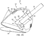
- the device 10 preferably includes a securing mechanism 32 (see FIGS. 2C , 8A and 8B ) coupled to a bottom of the housing 12.
- the securing mechanism 32 as illustrated is a solid flap, which can have the same perimeter as the base of the housing 12. This flap is attached only at the front bottom part of the device 10 so as to create a hinge.
- the flap is also preferably attached in the middle by two elastic bands.
- the flap can be constructed of a high-density foam material, cardboard or plastic.
- the flap is constructed of a microfiber material.
- the external face of the bottom flap has an adhesive material that has a protective cover until it is needed.
- the surgeon When surgery begins and the surgeon brings the device 10 up to the operative field he can secure the device anywhere on top of the drapes by removing a protective cover from an adhesive bottom of the securing mechanism 32 and securing the device 10 anywhere on the operative field.
- the device 10 can also be secured by an assistant to a sterile equipment tray, from which a medical videoscope can then be passed to the surgeon.
- the function of the securing mechanism 32 as a flap is so that the scope can be inserted vertically, but when it is not in use the flap 32 allows the device 10 to rotate horizontally and rest on the drapes while the scope remains inside the device. Although the device 10 rotates along the hinge of the flap 32, the flap maintains the device 10 securely attached to the drapes with the adhesive coating.
- the device 10 may be constructed without the flap 32 and adhesive can be placed directly on the bottom of the device. Furthermore, the device 10 can be secured to any surface through such components such as, but not limited to, adhesives, screws, magnetism, mounts, and clips. Moreover, the device 10 can remain unsecured to any surface and be put on and pulled off the scope as needed during the medical procedure.
- the device 10 preferably includes an opening adapter 33 to effectively reduce the diameter of the opening 16 for accommodating smaller diameter videoscopes.
- the adapter 33 includes a flexible longitudinal stem 35 having a base portion 37 at one end of the stem and a reduced opening portion 39 at another end of the stem.
- the base portion 37 is coupled to a lower portion of the housing 12.
- the flexible longitudinal stem 35 is bendable in order to insert the reduced opening portion 39 into the opening 16 of the housing 12.
- the opening adapter 33 is preferably made of a flexible medical grade silicone plastic, but can also be constructed out of other flexible materials.
- the diameter of the reduced opening portion 39 is shown by way of example to be 5 mm, but other sizes can be employed without departing from the scope of the present invention.
- FIGS. 2A through 2C show the white balance device 10 with the heating mechanism 28 removed for simplicity of illustration.
- the device 10 preferably includes an inner chamber or center sheath 34 (see also FIGS. 4A through 4C ) defining the canal 18 and accommodated within a cavity of the housing.
- the canal 18 and the center sheath 34 are sized and shaped to accommodate a medical videoscope when inserted therein.
- the canal 18 and the sheath 34 preferably extend directly down the center of the device 10 from an upper front to a lower back portion.
- the sheath 34 can alternatively extend directly down a center or lateral to a center of the device 10.
- the location of the sheath 34 can be in any configuration as long as uniform thermal conductivity is achieved.
- the length of the sheath 34 is preferably about 3 inches long but can be as long as about 8 inches or as short as about 0.5 inches.
- the sheath 34 preferably has the shape of a tube.
- the tubular diameter inside the sheath can be about 5 mm, 10 mm, or any other practical diameter depending on the size and shape of the medical instrument to be inserted therein.
- One embodiment of the sheath 34 is preferably constructed of stainless steel or aluminum for good heat transfer properties, but may also be constructed of, but not limited to, a thin piece of high-density polyurethane, etha, viscoelastic or latex foam.
- the sheath 34 can also be made of rubber-like foam or thin plastic. A water impermeable fabric can also be used.
- the sheath 34 can alternatively be constructed of silicone or a rubber-like material.
- the sheath 34 can all be white or any other color.
- the self-sealing mechanism 30 is disposed at least partly within the canal 18 and the sheath 34 to prevent the surgical defogging material 26 from spilling out of the opening 16 of the device 10.
- the canal 18 or the sheath 34 preferably accommodates the defogging material 26 such as an antifog, lens cleaning agent, or surfactant solution, and may lead into or define a reservoir which is filled with the defogging material.
- the self-sealing mechanism 30 generally has the shape of a tube within a tube.
- the self-sealing mechanism 30 is made of a flexible medical grade silicone plastic.
- the self-sealing mechanism 30 is configured to allow a medical videoscope to enter a reservoir at the second end 22 of the canal 18 or inner end of the sheath 34 and make contact with the defogging material 26 and prevent the defogging material when in the form of liquid or gel from spilling out of the opening 16 of the housing 12 when the device 10 is turned upside down while the scope is removed from the device.
- the self-sealing mechanism 30 is configured to function as a type of one-way valve to allow passage therethrough in only one direction.
- a preferred embodiment of the self-sealing mechanism 30 includes an upper lip 51 for being seated on the first end 20 of the sheath 34.
- the self-sealing mechanism 30 further includes three flaps or pockets 53 depending downwardly from the upper lip 51 and spaced from one another circumferentially about a periphery of the self-sealing mechanism 30 such that the pockets are facing an inner surface of the sheath 34.
- the self-sealing mechanism 30 has a center tube or duck bill 55 depending downwardly from the upper lip 51 and defines a slit 57 at a bottom portion thereof for permitting a scope to pass therethrough.
- the center tube 55 is spaced radially inwardly of the pockets 53 so as to define a space between the center tube and the pockets.
- the self-sealing mechanism 30 prevents liquid from spilling out by creating and trapping liquid in the space around the first end 20 of the canal 18 or the sheath 34 defining the canal.
- the sheath 34 is turned with the reservoir down all the liquid will fall into the reservoir.
- the sheath 34 and the reservoir are turned upside down, the liquid slides along the side of the sheath 34 and enters the space of the self-sealing mechanism 30 surrounding the distal end of the sheath 34.
- the pockets 53 relieve pressure caused by a scope entering the reservoir. With a sealed enclosure provided by the center tube 55, as a scope is inserted through the center tube 55 pressure builds as the scope takes up space within the reservoir.
- the center tube or duck bill 55 is configured to prevent fluid or air from escaping, and thus the pressure build-up tries to force the scope out of the reservoir.
- the pockets 53 overcome such detrimental pressure build-up upon the scope. As the pressure builds, instead of pushing the scope out of the reservoir, the pockets deform taking up less space and balancing out the pressure. In other words, the pockets 53 are configured to serve as a pressure compensating system of the self-sealing mechanism 30.
- the self-sealing mechanism can resemble a heart valve or be made with a flap and a hinge that only opens in one direction.
- the self-sealing mechanism can also resemble a valve in a human vein.
- the self-sealing mechanism can be a ball and socket mechanism in which a ball inside the reservoir plugs the hole when the reservoir is turned upside down but still allows for the scope to enter in the other direction.
- the self-sealing mechanism is preferably constructed from a resilient plastic or other rubber-like material. It can also be made from a high-density foam or water impermeable fabric.
- the self-sealing mechanism can also be made of metal, aluminum, or silicone plastic.
- the self-sealing mechanism can be any configuration known to a person skilled in the art to prevent leakage and splash back of fluid.
- the white balancing reference material 24 is disposed adjacent to the second end 22 of the canal 18 such that when a lens 25 of a scope 31 is placed into the reservoir, the lens approaches within a predetermined distance of the reference material 24.
- the white balancing reference material 24 is preferably a true white, soft, non-scratch, absorbent material. The material must have a good light diffusing property. More preferably, the white balancing reference material 24 includes a sponge having a white color with a chromaticity of about D-65 or about a D-50 or about D-100.
- the white color of the white balancing reference material 24 is preferably equal parts of red, blue and green, but can have slight deviations designed to match the camera system specifications of the medical videoscope 31 to be white balanced by the reference material.
- the white balancing reference material 24 can be square in shape or in the shape of a rectangle. Alternatively the reference material 24 can be in the shape of an ellipse or a circle. The shape of the reference material 24 is dependent on the shape of the scope to be white balanced.
- the reference material 24 can be about 1,4 to about 1/16 of an inch thick.
- the reference material 24 is made out of a low-density foam or other soft material which can be either hydrophobic or hydrophylic. Preferably, the reference material 24 is made out of a white medical grade closed cell foam.
- FIGS. 2B and SA through 5C show the shape of the white balancing reference material 24 in a preferred embodiment.
- the reference material 24 preferably defines an indentation or narrowing portion 36 which is small enough for the distal lens 25 of the videoscope 31 to come into contact with the narrowing portion 36 and not to be able to further enter the reference material.
- the narrowing portion 36 is configured to maintain a predetermined space or distance 41 between the lens and a white surface of a facing base portion 43 of the reference material.
- the space 41 is of a sufficient distance to allow for proper white balancing of the videoscope 31.
- the defogging material 26, preferably in the form of a gel or liquid, can be made of, but is not limited to, a combination of water, glycol, and a water-soluble wetting agent, alcohol, and a gelling agent.
- the defogging material 26 is made from 1 part poloxamer 188, 99 parts water.
- a commercially available wound cleaning surfactant solution such as ShurclenzTM can be diluted with water and used. It may also use any other non-ionic surfactant alone or in a mixture. Alcohol may also be used in the solution.
- a gelling agent it can be a starch or any super absorbent polymer.
- a defogging solution can be used, and it can be any commercially available surgical defogging solution such as, for example, F.R.E.D.TM or E.L.V.I.S.TM.
- the heating mechanism 28 is disposed adjacent to the reservoir of the second end 22 of the canal 18 or the sheath 34 so as to be in thermal communication therewith.
- the sheath 34 and the reservoir as part of the sheath are preferably made of stainless steel or aluminum for efficient heat transfer from the heating mechanism 28 to the defogging material 26 disposed within the reservoir.
- the heating mechanism 28 can include, for example, a heating element such as a wound 30 gauge copper wire or nichrome wire.
- the wire can be connected to a power source 40 such as a battery pack having a housing made of plastic (see FIG. 1 ) or to another source such as an AC outlet. When activated, electricity flows from the power source 40 through the heating element 38 so as to heat the reservoir and the defogging material 26 disposed therein.
- a thermistor or switch 27 having a thermal component may be placed in the electrical circuit of the heating mechanism 28 to turn off the flow of electricity when a predetermined temperature is reached by the defogging material 26 so as to allow the heating mechanism to maintain a constant temperature of the defogging material above body temperature for an extended period of time while being energized by the power source 40 such as, for example, only four AAA batteries 44 electrically connected in series, as shown in FIG. 1 . Although four AAA batteries 44 are shown by way of example, different size and different quantities of batteries may be used.
- a trigger or plunger 29 (see FIGS. 1 and 7 A through 7C ) communicates with the switch 27.
- the plunger 29 is preferably made of stainless steel or aluminum, but may be also be formed of plastic or other generally rigid materials. When the plunger 29 is pressed downwardly into the housing, the plunger initially closes the switch to electrically energize the heating mechanism 28 until the thermal component of the switch 27 opens the electrical circuit when the defogging material reaches the predetermined temperature.
- the device 10 can also include an alert mechanism 46 so that upon activation a user is notified that the device is being heated by the heating mechanism 28.
- the alert mechanism 46 can include a light such as an LED 48 (see FIG. 1 ) or an audible tone generator.
- a thermometer or heat sensitive paint may be used as an indicator of activation.
- the device 10 can also have a microfiber fabric 50 on all or part of the outer surface 14 of the housing 12 so that a scope lens can be wiped thereon and cleaned during a surgical procedure.
- the housing 12 preferably defines a ledge 61 and a depressed surface portion 63 which is covered by the microfiber 50 and against which a scope can be conveniently wiped clean.
- the microfiber 50 can be either permanently or removably attachable to the device 10.
- the microfiber 50 can be, but is not limited to, any combination of polyester and nylon.
- the sheath 34 and the reservoir may be constructed of stainless steel or aluminum, but any metal with good heat transfer properties can be used.
- the device 10 is a protector against fire hazards. This is because light from the scope is not allowed to be concentrated on any drapes or on the patient which could otherwise cause a bum or fire.
- the device 10 may also be packaged in combination with other medical videoscopic care products such as microfiber surgical sponges, trocar wipes, and a microfiber patient cleaning set.
- kit which contains this white balancing and defogging device of the present invention in combination with other medical videoscopic care products can be called a "laparoscopic care kit” or a “laparoscopic care pack.”
- FIG. 10 is a perspective view showing a device 10 embodying the present invention oriented to maintain a videoscope such as, for example, laparoscope 45 inserted therein in an upright position.
- a videoscope such as, for example, laparoscope 45
- FIG. 11 is a perspective view of the device 10 of FIG. 10 oriented to maintain the laparoscope 45 inserted therein in a resting position.
- the securing mechanism 32 of the device 10 serves a hinge.
- There is an adhesive in the bottom of the device 10 that allows the device to be secured to drapes or to a table and still allow for the scope 45 to rest freely. This allows for the scope 45 to remain inside the device 10 so as to prevent a fire hazard whenever the scope is not in use.
- the scope of the present invention is not limited to these embodiments.
- the white balancing reference material and defogging material are shown and described as being part of a single device, it should be understood that the white balancing reference material and defogging material can be disposed in separate devices working either simultaneously or non-simultaneously with one another without departing from the scope of the present invention.
- One skilled in the art may find other variations of these preferred embodiments which, nevertheless, fall within the scope and spirit of the present invention.
Landscapes
- Health & Medical Sciences (AREA)
- Life Sciences & Earth Sciences (AREA)
- Surgery (AREA)
- Engineering & Computer Science (AREA)
- Biomedical Technology (AREA)
- Molecular Biology (AREA)
- Biophysics (AREA)
- Nuclear Medicine, Radiotherapy & Molecular Imaging (AREA)
- Optics & Photonics (AREA)
- Pathology (AREA)
- Radiology & Medical Imaging (AREA)
- Veterinary Medicine (AREA)
- Public Health (AREA)
- Heart & Thoracic Surgery (AREA)
- Medical Informatics (AREA)
- Physics & Mathematics (AREA)
- Animal Behavior & Ethology (AREA)
- General Health & Medical Sciences (AREA)
- Pulmonology (AREA)
- Multimedia (AREA)
- Signal Processing (AREA)
- Otolaryngology (AREA)
- Physiology (AREA)
- Endoscopes (AREA)
- Instruments For Viewing The Inside Of Hollow Bodies (AREA)
Abstract
Description
- This application claims the benefit of
U.S. Provisional Application No. 60/763,472, filed on January 30, 2006 - This invention generally relates to a device for white balancing a camera, and more specifically relates to a device for white balancing a medical videoscopic camera system prior to videoscopic medical procedures, as well as optionally simultaneously or non-simultaneously applying a fog prohibiting agent to the distal lens of a medical videoscope such as, for example, an endoscope, laparoscope, bronchoscope, cystoscope or otoscope. The device combines a white balancing mechanism, protective mechanism, and defogging mechanism in one simple easy to use device.
- The color of light reflected off of a subject changes with the color of the light source. Unlike a human eye, a digital camera is unable to adapt to these changes. The human eye/brain automatically compensates for the color temperature of light falling on an object. When you move from the bright, blue-tinted sunlight to the dim, yellow-tinted indoor lighting, your eye automatically adjusts to the different color of light and changes your perception accordingly. If your brain knows it is looking at something white, it will look white in bright sunlight or inside even under a fluorescent light. Unfortunately, even the most expensive video cameras cannot automatically do what the eye does, so we have to show our cameras what we want them to read as "white" in any given scene.
- In most digital cameras, the illumination intensity and color temperature must be measured and adjusted to ensure that a white object is recorded as white. This process is often referred to as white balancing, and is a software or hardware option on all digital cameras. It is important with digital cameras to white balance manually for the absolute best video output results.
- White balancing is an important function that is carried out with all digital endoscopic and laparoscopic cameras prior to videoscopic medical procedures. Normally our eyes compensate for lighting conditions with different color temperatures. A digital camera needs to find a reference point which represents white. It will then calculate all the other colors based on this white point.
- The RGB system is one of the primary color models used to specify and represent colors in computer-controlled cameras and software. White is produced by combining equal parts of all three colors (red, green and blue) at levels of 100 percent. In white balancing a camera, a sensor on or within the camera averages the light within the scene and automatically adjusts the camera's internal color balance to zero-out any generalized color bias. By finding the difference between the white the camera sees and that of the internal reference white, the camera can adjust for the difference for every other color, thereby generating a more accurate and realistic video image. Even professional photographers who use digital still cameras carry a white reference card to properly white balance in order to capture the most accurate life-like images. It is amazing that today, in the advanced medical procedures requiring realistic and accurate video images, white balancing is rarely done correctly.
- The video color quality is very much dependant on the accuracy of the white balance performed prior to the medical procedure. This is especially important in laparoscopic and endoscopic cameras that are involved in life and death situations. A realistic video image is crucial when trying to differentiate between slight pigmentation changes in tissues while looking for inflammation, metastasis during cancer resections or diagnostic procedures.
- Often, doctors do not understand the importance of white balancing and so they will use a reference such as surgical gauze - which is actually full of holes and not truly white - to set the calibration. Moreover, white balancing is carried out in the open room where there is different light sources illuminating the "white" gauze sponge; this is a problem because the video inside the body will be generated using only the camera's fiber optic light source. Both of these mistakes generate an incorrect white balance point. Consequently, the video images generated often have a color shift away from the real colors. For photography, this is annoying. For medicine this can be dangerous. Moreover, doctors also often hold the scope too close to the white target distorting the camera's light, or too far exposing the white to room fluorescent lights and spot lights.
- Laparoscopic and endoscopic cameras are involved in life and death situations, such as trying to differentiate between slight pigmentation changes in tissues when looking for inflammation or metastasis during cancer resections. Another problem is that, currently, white balancing the medical videoscope during medical procedures is a hassle. The surgeon has to coordinate with the nurse for the right time to white balance. The doctor is often sterile and cannot press the white balance button on the camera equipment. He or she must hold the sterile scope facing the "white" gauze and at the same time synchronize with the nurse to press the white balance button in the equipment. This becomes complicated and time consuming because the nurse often is busy when the surgeon is ready to white balance or the surgeon is busy when the nurse is ready to white balance. This wastes time, and time is very expensive in the operating room.
- Additionally, from the birth of endoscopic and laparoscopic surgery to the present, surgeons have continually dealt with a persistent and annoying problem, the fogging of the scope lens. The fogging of the scope is very costly. When scopes fog up during surgery, the surgeon cannot see and must pause the surgery until the picture can be cleared up. This routine commonly occurs at least several times during every procedure. With the incredible costs relating to anesthesia and surgical staff, the wasted time in the aggregate equals hundreds and thousands of dollars.
- Condensation on the lens occurs because there are temperature differences which occur initially when the cold scope enters the warm moist body, and transiently during the procedure when the doctor coagulates tissue. Since many medical procedures are sterile, current methods to solve both these visualization problems are limited to messy anti-fog solutions and inaccurate white balancing techniques.
- Another major problem is that the white reference must often be sterile, so doctors typically use the "white" surgical gauze sponge to white balance. These sponges are in reality full of holes and actually not the ideal white. By white balancing with an off-white, that is illuminated by different lights with different color temperatures, doctors are settling for below optimum video image quality. Ultimately, this may distort the accuracy of the white balance and diminish the quality and the true reproduction of the color in the video generated from inside the body during the medical procedure. Having below optimum video color quality could be dangerous as inflammation and cancer metastasis often presents as discreet color changes. This is becoming more and more important as endoscopes and laparoscopes are becoming vital diagnostic instruments.
- In an aspect of the present invention, a device for white balancing a medical videoscope such as, for example, an endoscope or laparoscope includes a housing having an outer surface defining an opening, an interior of the housing defining a canal having a first end communicating with the opening and a second end terminating within the housing for receiving a distal lens of a medical videoscope, and a white balancing reference material disposed adjacent to the second end of the canal.
- It is an object of the present invention to provide a device for a multi-function device which is used for white balancing medical videoscopic cameras as well as an applicator for applying an anti-fog agent such as a liquid, gel or coating to the medical videoscope prior to a medical procedure.
- The present invention entails a small, sterile, single patient use, disposable device containing an internal canal with a true white colored target at the end of the canal. The true white color inside the device is formulated to match the RGB combination most commonly used as internal reference true white for medical videoscopic digital camera systems. The target can be a painted surface, fabric pad, or another cushioning material, preferably a foam sponge. The target is designed to allow a space for the light to reflect, preferably with a concave space in the center of the foam sponge. Contained within the canal or in a reservoir surrounding the sponge is an anti-fog agent used to prevent fogging of the scope. This agent is preferably a surfactant wound cleaning solution that both inhibits fog and aids in the cleaning of the scope.
- The device is sterile and is opened prior to beginning a medical procedure. After the device is opened on a supply table, the nurse or doctor can place the device over the distal end of the medical videos cope. Inside the device, the distal lens of the scope faces a white material that covers the entire viewing area. The doctor or nurse then presses the white balance button on the camera equipment and the digital camera uses the white sponge as the reference white and properly executes the white balance calibration. The white target is optionally submerged in or impregnated with an anti-fog agent that is simultaneously or non-simultaneously applied to the distal lens upon the insertion of the distal scope into the device. The defogging mechanism can be activated and an antifog agent applied to the scope at the beginning and intermittently during the procedure. The device provides an environment for the scope which facilitates easy and accurate white balancing for medical videoscopes prior to and during medical procedures.
- More specifically, the present invention relates to a single patient use, sterile device that contains a tunnel space within it. At the innermost end of the tunnel is contained a white colored light diffusing material. The material can be a colored surface cushion, fabric pad, or foam sponge. The material is impregnated or submerged in an anti-fog agent such as a liquid, a gel, a coating, or a surfactant cleaning solution which also has antifog properties. The white sponge has a specifically formulated white color to facilitate white balancing. White is generated from the equal combination of different colors. The true white material in the device is the same RGB combination most commonly used as internal reference white for medical videoscopic digital camera systems. The true white material can also be impregnated with a wound cleaning surfactant solution or be used to scrub the distal lens while the scope is inserted in the device.
- The device is placed over the distal lens of a medical videoscope such as an endoscope or laparoscope. By placing the scope inside the device and then activating a white balance button on the camera equipment, the scope is white balanced' correctly and conveniently. The optimum white balance is achieved by not only using a true white reference but also by illuminating the white reference solely with the camera's light source. During medical procedures, white balancing is currently done in the open room which is illuminated by fluorescent lights and spotlights. This conventional way of white balancing is a mistake, since inside the body the only light illuminating the organs is a fiber optic light.
- Additionally, when the scope is inside the device for white balancing, the lens is making simultaneous contact with a solution or agent formulated to inhibit fog on the medical videoscope or aid in cleaning blood and debris from the lens. The liquid additionally provides an improvement in visualization. Fog is a major problem during endoscopic surgery. When cold scopes are introduced into the warm moist body, condensation occurs. This condensation fogs the viewing area forcing the procedure to be delayed until it clears up.
- What is needed is a device that not only makes white balancing accurate and easy but also a device which includes a defogging mechanism. The defogging mechanism may be with the use of a cold anti-fog liquid or and electrical or exothermic mechanism that heats the anti-fog liquid. The device is opened prior to any medical procedure and placed over the distal lens of the medical videoscope. White balancing is performed by pressing the white balance button in the camera equipment. The device is then removed from the distal scope immediately prior to its insertion into the body and can be reinserted into the device whenever the scope is removed from the body. The device is sterile, for single patient use, and can be discarded after each procedure or kept on the distal scope until the scope is resterilized.
- Additionally even with a perfect white, it is vital that the scope lens be held at a certain minimum distance from the white target for the light to properly reflect. The device provides a mechanism that provides a consistent, set space between the scope lens and the true white target. This space is also part of the defogging mechanism. Within the device a collection of an antifog agent is kept. When the doctor decides, he can activate a mechanism which forces the defogging liquid to rush out of the reservoir and into the space between the white target and the scope. The scope lens is thoroughly covered with the antifog agent.
- These objects and features of the invention will be more clearly understood from the following detailed description along with the accompanying drawing figures, wherein:
-
FIG. 1 is a perspective view of a white balance device embodying the present invention. -
FIG. 2A is a side view of the device ofFIG. 1 with heating components removed. -
FIG. 2B is a side view of the device with a medical videoscope inserted therein. -
FIG. 2C is a perspective view of the device showing a securing mechanism. -
FIG. 3A is a front perspective view showing a housing of the device. -
FIG. 3B is a front view of the housing ofFIG. 3A . -
FIG. 3C is a cross-sectional view of the housing taken along thelines 3C-3C ofFIG. 3B . -
FIG. 3D is a top view of the housing. -
FIG. 3E is a cross-sectional view of the housing taken along thelines 3E-3E ofFIG. 3D . -
FIG. 3F is a cross-sectional view of the housing taken along thelines 3F-3F ofFIG. 3D . -
FIG. 4A is a perspective view of an embodiment of an inner chamber of a white balance device. -
FIG. 4B is a plan view of the inner chamber. -
FIG. 4C is a cross-sectional view of the inner chamber taken along thelines 4C-4C ofFIG. 4B . -
FIG. 5A is a perspective view of a white balancing reference material. -
FIG. 5B is a top plan view of the reference material. -
FIG. 5C is a cross-sectional view of the reference material taken along thelines 5C-5C ofFIG. 5B . -
FIG. 6A is a perspective view of an embodiment of a self-sealing mechanism of a white balance device. -
FIG. 6B is a bottom plan view of the self-sealing mechanism. -
FIG. 6C is a cross-sectional view of the self-sealing mechanism taken along thelines 6C-6C ofFIG. 6B . -
FIG. 6D is a top plan view of the self-sealing mechanism. -
FIG. 7 A is a perspective view of a trigger of a heat-activating switch. -
FIG. 7B is a side view of the trigger. -
FIG. 7C is a plan view of the trigger. -
FIG. 8A is a perspective view of a securing mechanism. -
FIG. 8B is a plan view of the securing mechanism. -
FIG. 9A is a perspective view of an insertion hole adapter. -
FIG. 9B is a plan view of the adapter. -
FIG. 9C is a cross-sectional view of the adapter taken along thelines 9C-9C ofFIG. 9B . -
FIG. 10 is a perspective view showing a white balance device embodying the present invention oriented to maintain a laparoscope inserted therein in an upright position. -
FIG. 11 is a perspective view showing the device ofFIG. 10 oriented to maintain the laparoscope inserted therein in a resting position. - With reference to
FIGS. 1 through 3F , a white balance device embodying the present invention is indicated generally by thereference number 10. Thedevice 10 comprises a housing orouter shell 12. Thehousing 12 has anouter surface 14 defining anopening 16 for inserting therein a medical videoscope such as a laparoscope or endoscope. An interior of thehousing 12 defines acanal 18 having afirst end 20 communicating with theopening 16 and asecond end 22 terminating within thehousing 12 for receiving a distal lens of a medical videoscope. A white balancing reference material 24 (seeFIGS. 5A through 5C ) is disposed within thehousing 12 adjacent to thesecond end 22 of thecanal 18. - The
device 10 preferably accommodates adefogging material 26 adjacent to thesecond end 22 of thecanal 18 for treating and preventing the distal lens of a medical videos cope from fogging during a medical procedure. Thedevice 10 preferably further comprises aheating mechanism 28 in thermal communication with thecanal 18 for heating an interior wall of the canal and thesurgical defogging material 26 disposed within the canal to further prevent the distal lens of a medical videoscope from fogging. Alternatively, theheating mechanism 28 can be in thermal communication with thecanal 18 for heating an interior wall of the canal to prevent a distal lens of a medical videoscope disposed in the canal from fogging when no defogging material is disposed in the canal. Thedevice 10 further comprises a self-sealing mechanism 30 (seeFIGS. 6A through 6D ) disposed at least partly within thecanal 18 and is configured for allowing a medical videoscope to enter the canal and make contact with thesurgical defogging material 26 and for preventing the surgical defogging material from spilling out of the canal. - Preferably, the housing or
shell 12 is made of an insulating foam material such as a medical grade polyurethane foam or any solid which can be a shock absorbing insulating material. Theshell 12 can be designed to protect the lens of a medical videoscope or any other type of instrument from damage prior, during, and after a surgical procedure. The material is preferably inexpensive since thedevice 10 is preferably disposable and for single patient use. An outer cover of theshell 12 preferably is constructed of high-density polyurethane, etha, viscoelastic, latex foams, and the like. The outer cover can also be made from rubber-like foam. A semi-flexible thermoplastic can also be used. The outer cover can also be made from insulating cardboard or a thick insulating fabric. The outer cover can alternatively be constructed out of a plastic frame covered by a silicone or insulating plastic. It is important that the material have good shock absorbing and insulating properties. - The
device 10 is preferably shaped as inFIG. 1 but can alternatively be made in any other practical shape such as a cube, square or spherical shape. Thedevice 10 can also have a tubular shape. Thedevice 10 can have rounded corners or square corners. Thedevice 10 exteriorly is preferably about 4 inches long, 3.5 inches wide, and 4 inches high, but generally can be as small as about 15 mm wide, 1 inch long, and 15 nun high. Alternatively thedevice 10 generally can be as large as about 6 inches wide, 6 inches long and 8 inches high. Clearly, thedevice 10 can be sized to accommodate the shape of any medical instrument used. - The
device 10 preferably includes a securing mechanism 32 (seeFIGS. 2C ,8A and 8B ) coupled to a bottom of thehousing 12. For example, the securingmechanism 32 as illustrated is a solid flap, which can have the same perimeter as the base of thehousing 12. This flap is attached only at the front bottom part of thedevice 10 so as to create a hinge. The flap is also preferably attached in the middle by two elastic bands. The flap can be constructed of a high-density foam material, cardboard or plastic. Preferably, the flap is constructed of a microfiber material. The external face of the bottom flap has an adhesive material that has a protective cover until it is needed. - When surgery begins and the surgeon brings the
device 10 up to the operative field he can secure the device anywhere on top of the drapes by removing a protective cover from an adhesive bottom of the securingmechanism 32 and securing thedevice 10 anywhere on the operative field. Thedevice 10 can also be secured by an assistant to a sterile equipment tray, from which a medical videoscope can then be passed to the surgeon. The function of the securingmechanism 32 as a flap is so that the scope can be inserted vertically, but when it is not in use theflap 32 allows thedevice 10 to rotate horizontally and rest on the drapes while the scope remains inside the device. Although thedevice 10 rotates along the hinge of theflap 32, the flap maintains thedevice 10 securely attached to the drapes with the adhesive coating. - Alternatively, the
device 10 may be constructed without theflap 32 and adhesive can be placed directly on the bottom of the device. Furthermore, thedevice 10 can be secured to any surface through such components such as, but not limited to, adhesives, screws, magnetism, mounts, and clips. Moreover, thedevice 10 can remain unsecured to any surface and be put on and pulled off the scope as needed during the medical procedure. - As shown in
FIGS. 1 and 9A through 9C , thedevice 10 preferably includes anopening adapter 33 to effectively reduce the diameter of theopening 16 for accommodating smaller diameter videoscopes. Theadapter 33 includes a flexiblelongitudinal stem 35 having abase portion 37 at one end of the stem and a reducedopening portion 39 at another end of the stem. As shown inFIG. 1 , thebase portion 37 is coupled to a lower portion of thehousing 12. The flexiblelongitudinal stem 35 is bendable in order to insert the reducedopening portion 39 into theopening 16 of thehousing 12. - The opening
adapter 33 is preferably made of a flexible medical grade silicone plastic, but can also be constructed out of other flexible materials. The diameter of the reducedopening portion 39 is shown by way of example to be 5 mm, but other sizes can be employed without departing from the scope of the present invention. -
FIGS. 2A through 2C show thewhite balance device 10 with theheating mechanism 28 removed for simplicity of illustration. Thedevice 10 preferably includes an inner chamber or center sheath 34 (see alsoFIGS. 4A through 4C ) defining thecanal 18 and accommodated within a cavity of the housing. Thecanal 18 and thecenter sheath 34 are sized and shaped to accommodate a medical videoscope when inserted therein. Thecanal 18 and thesheath 34 preferably extend directly down the center of thedevice 10 from an upper front to a lower back portion. Thesheath 34 can alternatively extend directly down a center or lateral to a center of thedevice 10. The location of thesheath 34 can be in any configuration as long as uniform thermal conductivity is achieved. The length of thesheath 34 is preferably about 3 inches long but can be as long as about 8 inches or as short as about 0.5 inches. Thesheath 34 preferably has the shape of a tube. The tubular diameter inside the sheath can be about 5 mm, 10 mm, or any other practical diameter depending on the size and shape of the medical instrument to be inserted therein. One embodiment of thesheath 34 is preferably constructed of stainless steel or aluminum for good heat transfer properties, but may also be constructed of, but not limited to, a thin piece of high-density polyurethane, etha, viscoelastic or latex foam. Thesheath 34 can also be made of rubber-like foam or thin plastic. A water impermeable fabric can also be used. Thesheath 34 can alternatively be constructed of silicone or a rubber-like material. Thesheath 34 can all be white or any other color. - As mentioned above, preferably the self-sealing
mechanism 30 is disposed at least partly within thecanal 18 and thesheath 34 to prevent thesurgical defogging material 26 from spilling out of theopening 16 of thedevice 10. Thecanal 18 or thesheath 34 preferably accommodates thedefogging material 26 such as an antifog, lens cleaning agent, or surfactant solution, and may lead into or define a reservoir which is filled with the defogging material. - An example of the self-sealing
mechanism 30 is illustrated with reference toFIGS. 6A through 6D . The self-sealingmechanism 30 generally has the shape of a tube within a tube. Preferably, the self-sealingmechanism 30 is made of a flexible medical grade silicone plastic. The self-sealingmechanism 30 is configured to allow a medical videoscope to enter a reservoir at thesecond end 22 of thecanal 18 or inner end of thesheath 34 and make contact with thedefogging material 26 and prevent the defogging material when in the form of liquid or gel from spilling out of theopening 16 of thehousing 12 when thedevice 10 is turned upside down while the scope is removed from the device. In other words, the self-sealingmechanism 30 is configured to function as a type of one-way valve to allow passage therethrough in only one direction. - As shown in
FIGS. 6A through 6D , a preferred embodiment of the self-sealingmechanism 30 includes anupper lip 51 for being seated on thefirst end 20 of thesheath 34. The self-sealingmechanism 30 further includes three flaps orpockets 53 depending downwardly from theupper lip 51 and spaced from one another circumferentially about a periphery of the self-sealingmechanism 30 such that the pockets are facing an inner surface of thesheath 34. The self-sealingmechanism 30 has a center tube or duck bill 55 depending downwardly from theupper lip 51 and defines aslit 57 at a bottom portion thereof for permitting a scope to pass therethrough. The center tube 55 is spaced radially inwardly of thepockets 53 so as to define a space between the center tube and the pockets. - The self-sealing
mechanism 30 prevents liquid from spilling out by creating and trapping liquid in the space around thefirst end 20 of thecanal 18 or thesheath 34 defining the canal. When thesheath 34 is turned with the reservoir down all the liquid will fall into the reservoir. As thesheath 34 and the reservoir are turned upside down, the liquid slides along the side of thesheath 34 and enters the space of the self-sealingmechanism 30 surrounding the distal end of thesheath 34. Thepockets 53 relieve pressure caused by a scope entering the reservoir. With a sealed enclosure provided by the center tube 55, as a scope is inserted through the center tube 55 pressure builds as the scope takes up space within the reservoir. The center tube or duck bill 55 is configured to prevent fluid or air from escaping, and thus the pressure build-up tries to force the scope out of the reservoir. Thepockets 53 overcome such detrimental pressure build-up upon the scope. As the pressure builds, instead of pushing the scope out of the reservoir, the pockets deform taking up less space and balancing out the pressure. In other words, thepockets 53 are configured to serve as a pressure compensating system of the self-sealingmechanism 30. - Alternatively, the self-sealing mechanism can resemble a heart valve or be made with a flap and a hinge that only opens in one direction. The self-sealing mechanism can also resemble a valve in a human vein. Moreover, the self-sealing mechanism can be a ball and socket mechanism in which a ball inside the reservoir plugs the hole when the reservoir is turned upside down but still allows for the scope to enter in the other direction. The self-sealing mechanism is preferably constructed from a resilient plastic or other rubber-like material. It can also be made from a high-density foam or water impermeable fabric. The self-sealing mechanism can also be made of metal, aluminum, or silicone plastic. The self-sealing mechanism can be any configuration known to a person skilled in the art to prevent leakage and splash back of fluid.
- As shown in
FIGS. 2A through 2C , the whitebalancing reference material 24 is disposed adjacent to thesecond end 22 of thecanal 18 such that when alens 25 of ascope 31 is placed into the reservoir, the lens approaches within a predetermined distance of thereference material 24. The whitebalancing reference material 24 is preferably a true white, soft, non-scratch, absorbent material. The material must have a good light diffusing property. More preferably, the whitebalancing reference material 24 includes a sponge having a white color with a chromaticity of about D-65 or about a D-50 or about D-100. The white color of the whitebalancing reference material 24 is preferably equal parts of red, blue and green, but can have slight deviations designed to match the camera system specifications of themedical videoscope 31 to be white balanced by the reference material. The whitebalancing reference material 24 can be square in shape or in the shape of a rectangle. Alternatively thereference material 24 can be in the shape of an ellipse or a circle. The shape of thereference material 24 is dependent on the shape of the scope to be white balanced. Thereference material 24 can be about 1,4 to about 1/16 of an inch thick. Thereference material 24 is made out of a low-density foam or other soft material which can be either hydrophobic or hydrophylic. Preferably, thereference material 24 is made out of a white medical grade closed cell foam. -
FIGS. 2B and SA through 5C show the shape of the whitebalancing reference material 24 in a preferred embodiment. Thereference material 24 preferably defines an indentation or narrowingportion 36 which is small enough for thedistal lens 25 of thevideoscope 31 to come into contact with the narrowingportion 36 and not to be able to further enter the reference material. The narrowingportion 36 is configured to maintain a predetermined space ordistance 41 between the lens and a white surface of a facingbase portion 43 of the reference material. Thespace 41 is of a sufficient distance to allow for proper white balancing of thevideoscope 31. - The
defogging material 26, preferably in the form of a gel or liquid, can be made of, but is not limited to, a combination of water, glycol, and a water-soluble wetting agent, alcohol, and a gelling agent. Preferably, when in the form of a liquid, thedefogging material 26 is made from 1 part poloxamer 188, 99 parts water. A commercially available wound cleaning surfactant solution such as Shurclenz™ can be diluted with water and used. It may also use any other non-ionic surfactant alone or in a mixture. Alcohol may also be used in the solution. If a gelling agent is used, it can be a starch or any super absorbent polymer. Alternatively, a defogging solution can be used, and it can be any commercially available surgical defogging solution such as, for example, F.R.E.D.™ or E.L.V.I.S.™. - With reference to
FIG. 1 , theheating mechanism 28 is disposed adjacent to the reservoir of thesecond end 22 of thecanal 18 or thesheath 34 so as to be in thermal communication therewith. Thesheath 34 and the reservoir as part of the sheath are preferably made of stainless steel or aluminum for efficient heat transfer from theheating mechanism 28 to thedefogging material 26 disposed within the reservoir. Theheating mechanism 28 can include, for example, a heating element such as awound 30 gauge copper wire or nichrome wire. The wire can be connected to apower source 40 such as a battery pack having a housing made of plastic (seeFIG. 1 ) or to another source such as an AC outlet. When activated, electricity flows from thepower source 40 through the heating element 38 so as to heat the reservoir and thedefogging material 26 disposed therein. - A thermistor or switch 27 having a thermal component may be placed in the electrical circuit of the
heating mechanism 28 to turn off the flow of electricity when a predetermined temperature is reached by thedefogging material 26 so as to allow the heating mechanism to maintain a constant temperature of the defogging material above body temperature for an extended period of time while being energized by thepower source 40 such as, for example, only fourAAA batteries 44 electrically connected in series, as shown inFIG. 1 . Although fourAAA batteries 44 are shown by way of example, different size and different quantities of batteries may be used. Preferably, a trigger or plunger 29 (seeFIGS. 1 and 7 A through 7C ) communicates with theswitch 27. Theplunger 29 is preferably made of stainless steel or aluminum, but may be also be formed of plastic or other generally rigid materials. When theplunger 29 is pressed downwardly into the housing, the plunger initially closes the switch to electrically energize theheating mechanism 28 until the thermal component of theswitch 27 opens the electrical circuit when the defogging material reaches the predetermined temperature. - The
device 10 can also include analert mechanism 46 so that upon activation a user is notified that the device is being heated by theheating mechanism 28. For example, thealert mechanism 46 can include a light such as an LED 48 (seeFIG. 1 ) or an audible tone generator. Alternatively a thermometer or heat sensitive paint may be used as an indicator of activation. - The
device 10 can also have amicrofiber fabric 50 on all or part of theouter surface 14 of thehousing 12 so that a scope lens can be wiped thereon and cleaned during a surgical procedure. Thehousing 12 preferably defines aledge 61 and adepressed surface portion 63 which is covered by themicrofiber 50 and against which a scope can be conveniently wiped clean. Themicrofiber 50 can be either permanently or removably attachable to thedevice 10. Themicrofiber 50 can be, but is not limited to, any combination of polyester and nylon. - As mentioned above, the
sheath 34 and the reservoir may be constructed of stainless steel or aluminum, but any metal with good heat transfer properties can be used. - Because a medical videoscope is submerged in the defogging material in the form of a liquid or gel, the
device 10 is a protector against fire hazards. This is because light from the scope is not allowed to be concentrated on any drapes or on the patient which could otherwise cause a bum or fire. - The
device 10 may also be packaged in combination with other medical videoscopic care products such as microfiber surgical sponges, trocar wipes, and a microfiber patient cleaning set. The kit which contains this white balancing and defogging device of the present invention in combination with other medical videoscopic care products can be called a "laparoscopic care kit" or a "laparoscopic care pack." -
FIG. 10 is a perspective view showing adevice 10 embodying the present invention oriented to maintain a videoscope such as, for example,laparoscope 45 inserted therein in an upright position. -
FIG. 11 is a perspective view of thedevice 10 ofFIG. 10 oriented to maintain thelaparoscope 45 inserted therein in a resting position. The securingmechanism 32 of thedevice 10 serves a hinge. There is an adhesive in the bottom of thedevice 10 that allows the device to be secured to drapes or to a table and still allow for thescope 45 to rest freely. This allows for thescope 45 to remain inside thedevice 10 so as to prevent a fire hazard whenever the scope is not in use. - While the above invention has been described with reference to certain preferred embodiments, the scope of the present invention is not limited to these embodiments. For example, although the white balancing reference material and defogging material are shown and described as being part of a single device, it should be understood that the white balancing reference material and defogging material can be disposed in separate devices working either simultaneously or non-simultaneously with one another without departing from the scope of the present invention. One skilled in the art may find other variations of these preferred embodiments which, nevertheless, fall within the scope and spirit of the present invention.
Claims (12)
- A device for white balancing a medical videoscope (31), comprising:a housing (12) having an outer surface (14) defining an opening (16), an interior of the housing (12) defining a canal (18) having a first end (20) communicating with the opening and a second end (22) terminating within the housing (12) for receiving a distal lens (25) of a medical videoscope (31); anda white balancing reference material (24) disposed adjacent to the second end (22) of the canal (18),characterized in thatthe white balancing reference material (24) includes a sponge.
- A device as defined in claim 1, further comprising a surgical defogging material (26) held by the sponge.
- A device as defined in claim 1, wherein the white balancing reference material (24) has a white color with a chromaticity in the range of D-50 to D-100.
- A device as defined in claim 1, further comprising a surgical defogging material (26) disposed within the canal (18).
- A device as defined in claim 4, further comprising a mechanism in thermal communication with the canal for heating the surgical defogging material (26).
- A device as defined in claim 5, wherein the mechanism includes a heating element (38) and a DC battery (44) or a source of electrical current (40) electrically coupled to the heating element (38).
- A device as defined in claim 6, further comprising a self-sealing mechanism disposed within the canal, the self-sealing mechanism (30) being configured to allow for a medial videoscope (31) to enter the canal (18) and make contact with the surgical defogging material (26) and to prevent the surgical defogging material (26) from spilling out of the canal (18).
- A device as defined in claim 7, wherein the self-sealing mechanism (30) is configured as a one-way valve.
- A device as defined in claim 7, wherein the self-sealing mechanism includes:a tube or duck bill (55) defining a slit (57) configured for allowing a scope (31) to enter through the slit (57) and to prevent surgical defogging material (26) from escaping through the slit (57); andat least one pocket (53) disposed at least partly peripherally about the tube (55), the at least one pocket (53) being configured for deforming to relieve pressure build-up between the tube (55) and the at least one pocket (53) as a scope (31) enters the slit (57).
- A device as defined in one of the preceding claims, characterized in that the white balancing reference material (24) is disposed adjacent to the second end (22) of the canal (18) such that when a lens (25) of a scope (31) is placed into the reservoir, the lens approaches within a predetermined distance of the reference material (24).
- A device as defined in one of the preceding claims, characterized in that the reference material (24) defines an indentation or narrowing portion which is small enough for the distal lens (25) of the videoscope (31) to come into contact with the narrowing portion and not to be able to further enter the reference material (24).
- A device as defined in one of the preceding claims, characterized in that the narrowing portion is configured to maintain a predetermined space or distance between the lens (25) and a white surface of a facing base portion of the reference material (24).
Applications Claiming Priority (2)
| Application Number | Priority Date | Filing Date | Title |
|---|---|---|---|
| US76347206P | 2006-01-30 | 2006-01-30 | |
| EP07709877.0A EP1981390B1 (en) | 2006-01-30 | 2007-01-29 | Device for white balancing and applying an anti-fog agent to medical videoscopes prior to medical procedures |
Related Parent Applications (2)
| Application Number | Title | Priority Date | Filing Date |
|---|---|---|---|
| EP07709877.0A Division-Into EP1981390B1 (en) | 2006-01-30 | 2007-01-29 | Device for white balancing and applying an anti-fog agent to medical videoscopes prior to medical procedures |
| EP07709877.0A Division EP1981390B1 (en) | 2006-01-30 | 2007-01-29 | Device for white balancing and applying an anti-fog agent to medical videoscopes prior to medical procedures |
Publications (1)
| Publication Number | Publication Date |
|---|---|
| EP3150104A1 true EP3150104A1 (en) | 2017-04-05 |
Family
ID=38327971
Family Applications (3)
| Application Number | Title | Priority Date | Filing Date |
|---|---|---|---|
| EP07709877.0A Not-in-force EP1981390B1 (en) | 2006-01-30 | 2007-01-29 | Device for white balancing and applying an anti-fog agent to medical videoscopes prior to medical procedures |
| EP13177779.9A Not-in-force EP2659829B1 (en) | 2006-01-30 | 2007-01-29 | Device for white balancing and applying an anti-fog agent to medical videoscopes prior to medical procedures |
| EP16186613.2A Withdrawn EP3150104A1 (en) | 2006-01-30 | 2007-01-29 | Device for white balancing and applying an anti-fog agent to medical videoscopes prior to medical procedures |
Family Applications Before (2)
| Application Number | Title | Priority Date | Filing Date |
|---|---|---|---|
| EP07709877.0A Not-in-force EP1981390B1 (en) | 2006-01-30 | 2007-01-29 | Device for white balancing and applying an anti-fog agent to medical videoscopes prior to medical procedures |
| EP13177779.9A Not-in-force EP2659829B1 (en) | 2006-01-30 | 2007-01-29 | Device for white balancing and applying an anti-fog agent to medical videoscopes prior to medical procedures |
Country Status (7)
| Country | Link |
|---|---|
| US (1) | US8152717B2 (en) |
| EP (3) | EP1981390B1 (en) |
| JP (1) | JP5266065B2 (en) |
| KR (1) | KR101250611B1 (en) |
| CN (1) | CN101374452B (en) |
| ES (1) | ES2614487T3 (en) |
| WO (1) | WO2007089719A2 (en) |
Families Citing this family (66)
| Publication number | Priority date | Publication date | Assignee | Title |
|---|---|---|---|---|
| CN101022759B (en) | 2004-04-05 | 2010-05-26 | 菲舍尔和佩克尔保健有限公司 | Lens warming device |
| US8915842B2 (en) | 2008-07-14 | 2014-12-23 | Ethicon Endo-Surgery, Inc. | Methods and devices for maintaining visibility and providing irrigation and/or suction during surgical procedures |
| US9050036B2 (en) | 2007-06-19 | 2015-06-09 | Minimally Invasive Devices, Inc. | Device for maintaining visualization with surgical scopes |
| JP2009213673A (en) * | 2008-03-11 | 2009-09-24 | Fujinon Corp | Endoscope system and endoscope inspecting method |
| EP2361034B1 (en) | 2008-12-10 | 2014-07-30 | Minimally Invasive Devices, Inc. | Systems and methods for optimizing and maintaining visualization of a surgical field during the use of surgical scopes |
| US10524645B2 (en) | 2009-06-18 | 2020-01-07 | Endochoice, Inc. | Method and system for eliminating image motion blur in a multiple viewing elements endoscope |
| US9474440B2 (en) | 2009-06-18 | 2016-10-25 | Endochoice, Inc. | Endoscope tip position visual indicator and heat management system |
| US10130246B2 (en) | 2009-06-18 | 2018-11-20 | Endochoice, Inc. | Systems and methods for regulating temperature and illumination intensity at the distal tip of an endoscope |
| US9078562B2 (en) | 2010-01-11 | 2015-07-14 | Minimally Invasive Devices, Inc. | Systems and methods for optimizing and maintaining visualization of a surgical field during the use of surgical scopes |
| JP5968886B2 (en) | 2010-08-04 | 2016-08-10 | ミニマリー インべーシブ デバイシーズ, インコーポレイテッド | System and method for optimizing and maintaining operative field visualization while using a surgical microscope |
| EP2700375B1 (en) * | 2010-09-02 | 2018-10-24 | Ecolab USA Inc. | Selective thermal treatment of medical instrument portions with thermal treatment system instrument holder |
| US10663714B2 (en) | 2010-10-28 | 2020-05-26 | Endochoice, Inc. | Optical system for an endoscope |
| US9706908B2 (en) | 2010-10-28 | 2017-07-18 | Endochoice, Inc. | Image capture and video processing systems and methods for multiple viewing element endoscopes |
| WO2012075487A2 (en) | 2010-12-03 | 2012-06-07 | Minimally Invasive Devices, Llc | Devices, systems, and methods for performing endoscopic surgical procedures |
| US10517464B2 (en) | 2011-02-07 | 2019-12-31 | Endochoice, Inc. | Multi-element cover for a multi-camera endoscope |
| US10912699B2 (en) | 2012-01-10 | 2021-02-09 | Alessio Pigazzi | Method of securing a patient onto an operating table when the patient is in a position such as the trendelenburg position and apparatus therefor including a kit |
| US10398292B2 (en) | 2013-03-14 | 2019-09-03 | Floshield, Inc. | Fluid dispensing control systems and methods |
| US10595714B2 (en) | 2013-03-28 | 2020-03-24 | Endochoice, Inc. | Multi-jet controller for an endoscope |
| US9636003B2 (en) | 2013-06-28 | 2017-05-02 | Endochoice, Inc. | Multi-jet distributor for an endoscope |
| WO2014182723A1 (en) * | 2013-05-07 | 2014-11-13 | Endochoice, Inc. | White balance enclosed for use with a multi-viewing elements endoscope |
| US9949623B2 (en) | 2013-05-17 | 2018-04-24 | Endochoice, Inc. | Endoscope control unit with braking system |
| US10064541B2 (en) | 2013-08-12 | 2018-09-04 | Endochoice, Inc. | Endoscope connector cover detection and warning system |
| USD758577S1 (en) * | 2013-09-03 | 2016-06-07 | Endochoice, Inc. | White balance enclosure cap for a medical device |
| ES2891080T3 (en) | 2013-09-18 | 2022-01-26 | Covidien Lp | laparoscopic visualization system |
| US9943218B2 (en) | 2013-10-01 | 2018-04-17 | Endochoice, Inc. | Endoscope having a supply cable attached thereto |
| US9795287B2 (en) | 2013-12-09 | 2017-10-24 | John Temple | System for simultaneously heating multiple surgical viewing instruments |
| US9968242B2 (en) | 2013-12-18 | 2018-05-15 | Endochoice, Inc. | Suction control unit for an endoscope having two working channels |
| EP3094280A1 (en) * | 2014-01-13 | 2016-11-23 | Covidien LP | Medical device cleaning system |
| WO2015112747A2 (en) | 2014-01-22 | 2015-07-30 | Endochoice, Inc. | Image capture and video processing systems and methods for multiple viewing element endoscopes |
| US10039442B2 (en) | 2014-02-07 | 2018-08-07 | Sur-Seal Corporation | Anti-fog film for an endoscope |
| USD767131S1 (en) | 2014-02-13 | 2016-09-20 | Covidien Lp | Laparoscopic visualization device |
| US20150313445A1 (en) * | 2014-05-01 | 2015-11-05 | Endochoice, Inc. | System and Method of Scanning a Body Cavity Using a Multiple Viewing Elements Endoscope |
| US11234581B2 (en) | 2014-05-02 | 2022-02-01 | Endochoice, Inc. | Elevator for directing medical tool |
| US9775502B2 (en) | 2014-05-06 | 2017-10-03 | Buffalo Filter Llc | Laparascope and endoscope cleaning and defogging device |
| CN111436896A (en) | 2014-07-21 | 2020-07-24 | 恩多巧爱思股份有限公司 | Multi-focus and multi-camera endoscope system |
| CN106687024B (en) | 2014-08-29 | 2020-10-09 | 恩多巧爱思股份有限公司 | System and method for varying the stiffness of an endoscope insertion tube |
| USD765840S1 (en) * | 2014-12-03 | 2016-09-06 | Buffalo Filter Llc | Laparoscope and endoscope cleaning and defogging device |
| US10080488B2 (en) | 2014-12-12 | 2018-09-25 | Medix3d LLC | Cleaning device for cleaning a scope, laparoscope or microscope used in surgery or other medical procedures and a method of using the device during surgical or other medical procedures |
| EP3235241B1 (en) | 2014-12-18 | 2023-09-06 | EndoChoice, Inc. | System for processing video images generated by a multiple viewing elements endoscope |
| WO2016112034A2 (en) | 2015-01-05 | 2016-07-14 | Endochoice, Inc. | Tubed manifold of a multiple viewing elements endoscope |
| CA2972482A1 (en) * | 2015-01-15 | 2016-07-21 | Covidien Lp | Device for accommodating surgical tool prior to and during medical procedures |
| CN104688171B (en) * | 2015-02-13 | 2016-06-29 | 浙江省人民医院 | A kind of special mirror surface antifogging device of endoscope-assistant surgery |
| US10376181B2 (en) | 2015-02-17 | 2019-08-13 | Endochoice, Inc. | System for detecting the location of an endoscopic device during a medical procedure |
| US10078207B2 (en) | 2015-03-18 | 2018-09-18 | Endochoice, Inc. | Systems and methods for image magnification using relative movement between an image sensor and a lens assembly |
| US10401611B2 (en) | 2015-04-27 | 2019-09-03 | Endochoice, Inc. | Endoscope with integrated measurement of distance to objects of interest |
| US10516865B2 (en) | 2015-05-17 | 2019-12-24 | Endochoice, Inc. | Endoscopic image enhancement using contrast limited adaptive histogram equalization (CLAHE) implemented in a processor |
| US20170119474A1 (en) | 2015-10-28 | 2017-05-04 | Endochoice, Inc. | Device and Method for Tracking the Position of an Endoscope within a Patient's Body |
| ES2928074T3 (en) | 2015-11-02 | 2022-11-15 | Buffalo Filter Llc | Fluid filtration, cleaning, and demisting device |
| EP3383244A4 (en) | 2015-11-24 | 2019-07-17 | Endochoice, Inc. | Disposable air/water and suction valves for an endoscope |
| EP3419497B1 (en) | 2016-02-24 | 2022-06-01 | Endochoice, Inc. | Circuit board assembly for a multiple viewing element endoscope using cmos sensors |
| US10292570B2 (en) | 2016-03-14 | 2019-05-21 | Endochoice, Inc. | System and method for guiding and tracking a region of interest using an endoscope |
| CN109310408B (en) | 2016-06-21 | 2021-11-23 | 安多卓思公司 | Endoscope system with multiple connection interfaces for connection to different video data signal sources |
| CN106108958B (en) * | 2016-07-18 | 2020-01-07 | 上海交通大学 | Clamping type laparoscope lens temperature control antifogging device |
| FR3056407B1 (en) * | 2016-09-27 | 2018-11-30 | Deltamedics | LARYNGE DEVICE COMPRISING A SLITTED TUBE AND A DISPLAY SCREEN |
| EP3539444A4 (en) | 2016-11-10 | 2019-11-20 | Kyocera Corporation | Body cavity observation system, trocar device, and method of operating body cavity observation system |
| CN106780384A (en) * | 2016-12-15 | 2017-05-31 | 上海交通大学 | A kind of the real-time of cold light source abdominal cavity image parameters self adaptation that be applicable goes smog method |
| US10368905B2 (en) | 2017-03-07 | 2019-08-06 | Carefusion 2200, Inc. | Trocar assembly with a cleaning element for use during a laparoscopic procedure |
| US10201396B2 (en) | 2017-03-07 | 2019-02-12 | Carefusion 2200, Inc. | Trocar assembly with a cleaning element for use during a laparoscopic procedure |
| US10398296B2 (en) | 2017-03-07 | 2019-09-03 | Carefusion 2200, Inc. | Trocar assembly with a cleaning element for use during a laparoscopic procedure |
| US20180344141A1 (en) | 2017-05-31 | 2018-12-06 | Carefusion 2200, Inc. | Scope with integral cleaning element for use during a laparoscopic procedure |
| USD868997S1 (en) | 2017-09-15 | 2019-12-03 | Adventist Health System/Sunbelt, Inc. | Scope warmer apparatus |
| US20190159665A1 (en) * | 2017-11-28 | 2019-05-30 | Covidien Lp | Devices for cleaning medical videoscopes |
| WO2020176717A1 (en) | 2019-02-28 | 2020-09-03 | Medix3d LLC | Scope cleaning device configured to be removably connected to a surgical tool |
| CN112998634A (en) * | 2021-02-20 | 2021-06-22 | 南京图格医疗科技有限公司 | Endoscope demisting, decontaminating and sterilizing device and method |
| CN113208549B (en) * | 2021-05-14 | 2023-06-16 | 宁波海泰科迈医疗器械有限公司 | Method and system for real-time monitoring and cleaning of laparoscopic lenses |
| WO2023111709A1 (en) * | 2021-12-15 | 2023-06-22 | Covidien Lp | Endoscope cleaning devices |
Citations (6)
| Publication number | Priority date | Publication date | Assignee | Title |
|---|---|---|---|---|
| US5111804A (en) * | 1989-02-15 | 1992-05-12 | Kabushiki Kaisha Toshiba | Electronic endoscope |
| DE4138128A1 (en) * | 1991-11-19 | 1993-05-27 | Lemke Gmbh | VIDEO SYSTEM FOR ENDOSCOPY |
| US20020022762A1 (en) * | 2000-02-18 | 2002-02-21 | Richard Beane | Devices and methods for warming and cleaning lenses of optical surgical instruments |
| DE10226582A1 (en) * | 2001-06-15 | 2002-12-19 | Asahi Optical Co Ltd | Electronic endoscope selects colour processing automatically to suit lamp type |
| EP1488731A1 (en) * | 2003-06-18 | 2004-12-22 | Olympus Corporation | Endoscope apparatus |
| US20050234301A1 (en) * | 2004-04-16 | 2005-10-20 | Gomez Ricardo A | Method and apparatus for heating and applying warm antifog solution to endoscopes as well as a distal lens protector |
Family Cites Families (9)
| Publication number | Priority date | Publication date | Assignee | Title |
|---|---|---|---|---|
| JPS645525A (en) * | 1987-06-29 | 1989-01-10 | Toshiba Corp | White balance control apparatus of endoscope |
| US4831437A (en) * | 1987-08-11 | 1989-05-16 | Olympus Optical Co., Ltd. | Video endoscope system provided with color balance adjusting means |
| US5274874A (en) * | 1992-03-13 | 1994-01-04 | Merocel Corporation | Endoscope cleaning and defogging apparatus |
| US6117070A (en) * | 1996-11-28 | 2000-09-12 | Fuji Photo Optical Co., Ltd. | Plug device for endoscopic instrument channel |
| US5852494A (en) * | 1997-03-17 | 1998-12-22 | Polartechnics Limited | Apparatus for checking the calibration of optical probes |
| US5880779A (en) * | 1997-06-09 | 1999-03-09 | Rhynes; Vincent | Sterile disposable white balance box |
| JP3811339B2 (en) * | 2000-08-07 | 2006-08-16 | オリンパス株式会社 | Endoscope system |
| JP4011888B2 (en) * | 2001-11-07 | 2007-11-21 | オリンパス株式会社 | Measuring endoscope device |
| CN101022759B (en) * | 2004-04-05 | 2010-05-26 | 菲舍尔和佩克尔保健有限公司 | Lens warming device |
-
2007
- 2007-01-29 US US11/908,447 patent/US8152717B2/en active Active
- 2007-01-29 WO PCT/US2007/002428 patent/WO2007089719A2/en active Application Filing
- 2007-01-29 JP JP2008552488A patent/JP5266065B2/en not_active Expired - Fee Related
- 2007-01-29 KR KR1020087020976A patent/KR101250611B1/en active IP Right Grant
- 2007-01-29 EP EP07709877.0A patent/EP1981390B1/en not_active Not-in-force
- 2007-01-29 CN CN2007800039705A patent/CN101374452B/en not_active Expired - Fee Related
- 2007-01-29 ES ES07709877.0T patent/ES2614487T3/en active Active
- 2007-01-29 EP EP13177779.9A patent/EP2659829B1/en not_active Not-in-force
- 2007-01-29 EP EP16186613.2A patent/EP3150104A1/en not_active Withdrawn
Patent Citations (6)
| Publication number | Priority date | Publication date | Assignee | Title |
|---|---|---|---|---|
| US5111804A (en) * | 1989-02-15 | 1992-05-12 | Kabushiki Kaisha Toshiba | Electronic endoscope |
| DE4138128A1 (en) * | 1991-11-19 | 1993-05-27 | Lemke Gmbh | VIDEO SYSTEM FOR ENDOSCOPY |
| US20020022762A1 (en) * | 2000-02-18 | 2002-02-21 | Richard Beane | Devices and methods for warming and cleaning lenses of optical surgical instruments |
| DE10226582A1 (en) * | 2001-06-15 | 2002-12-19 | Asahi Optical Co Ltd | Electronic endoscope selects colour processing automatically to suit lamp type |
| EP1488731A1 (en) * | 2003-06-18 | 2004-12-22 | Olympus Corporation | Endoscope apparatus |
| US20050234301A1 (en) * | 2004-04-16 | 2005-10-20 | Gomez Ricardo A | Method and apparatus for heating and applying warm antifog solution to endoscopes as well as a distal lens protector |
Also Published As
| Publication number | Publication date |
|---|---|
| EP1981390A4 (en) | 2013-03-27 |
| KR101250611B1 (en) | 2013-04-09 |
| CN101374452A (en) | 2009-02-25 |
| JP2009525068A (en) | 2009-07-09 |
| EP1981390B1 (en) | 2016-11-09 |
| JP5266065B2 (en) | 2013-08-21 |
| KR20080094080A (en) | 2008-10-22 |
| EP1981390A2 (en) | 2008-10-22 |
| EP2659829A3 (en) | 2013-12-11 |
| EP2659829B1 (en) | 2018-01-17 |
| ES2614487T3 (en) | 2017-05-31 |
| WO2007089719A3 (en) | 2007-12-13 |
| CN101374452B (en) | 2012-10-10 |
| WO2007089719A2 (en) | 2007-08-09 |
| US20080161646A1 (en) | 2008-07-03 |
| EP2659829A2 (en) | 2013-11-06 |
| US8152717B2 (en) | 2012-04-10 |
Similar Documents
| Publication | Publication Date | Title |
|---|---|---|
| EP1981390B1 (en) | Device for white balancing and applying an anti-fog agent to medical videoscopes prior to medical procedures | |
| US11284790B2 (en) | Laparoscopic visualization system | |
| AU2016206743B2 (en) | Device for accommodating surgical tool prior to and during medical procedures | |
| AU2005230803B2 (en) | Scope warming device | |
| WO2010007785A1 (en) | Lighting device | |
| US7803109B2 (en) | Method and apparatus for protecting the distal lens of endoscopes | |
| US20190159665A1 (en) | Devices for cleaning medical videoscopes | |
| WO2023111709A1 (en) | Endoscope cleaning devices | |
| US20210307591A1 (en) | Portable edoscope with side-mountable disposable portion | |
| WO2023073657A1 (en) | Pull tab including an integrated seal for use with an endoscope cleaning device | |
| Morton III | Endoscopic Forehead Rejuvenation: How to Set |
Legal Events
| Date | Code | Title | Description |
|---|---|---|---|
| PUAI | Public reference made under article 153(3) epc to a published international application that has entered the european phase |
Free format text: ORIGINAL CODE: 0009012 |
|
| STAA | Information on the status of an ep patent application or granted ep patent |
Free format text: STATUS: THE APPLICATION HAS BEEN PUBLISHED |
|
| AC | Divisional application: reference to earlier application |
Ref document number: 1981390 Country of ref document: EP Kind code of ref document: P |
|
| AK | Designated contracting states |
Kind code of ref document: A1 Designated state(s): AT BE BG CH CY CZ DE DK EE ES FI FR GB GR HU IE IS IT LI LT LU LV MC NL PL PT RO SE SI SK TR |
|
| STAA | Information on the status of an ep patent application or granted ep patent |
Free format text: STATUS: THE APPLICATION IS DEEMED TO BE WITHDRAWN |
|
| 18D | Application deemed to be withdrawn |
Effective date: 20171006 |