EP3138729A1 - Adjustable interface pressure device - Google Patents
Adjustable interface pressure device Download PDFInfo
- Publication number
- EP3138729A1 EP3138729A1 EP16185138.1A EP16185138A EP3138729A1 EP 3138729 A1 EP3138729 A1 EP 3138729A1 EP 16185138 A EP16185138 A EP 16185138A EP 3138729 A1 EP3138729 A1 EP 3138729A1
- Authority
- EP
- European Patent Office
- Prior art keywords
- inflatable tube
- inflatable
- tube
- providing
- inflation device
- Prior art date
- Legal status (The legal status is an assumption and is not a legal conclusion. Google has not performed a legal analysis and makes no representation as to the accuracy of the status listed.)
- Granted
Links
- 238000000034 method Methods 0.000 claims abstract description 14
- 239000006260 foam Substances 0.000 claims description 3
- 229920001971 elastomer Polymers 0.000 description 8
- 239000012530 fluid Substances 0.000 description 6
- 239000000806 elastomer Substances 0.000 description 4
- 239000000463 material Substances 0.000 description 4
- 239000004033 plastic Substances 0.000 description 4
- 229920003023 plastic Polymers 0.000 description 4
- 239000012858 resilient material Substances 0.000 description 4
- 239000005060 rubber Substances 0.000 description 4
- 230000006835 compression Effects 0.000 description 2
- 238000007906 compression Methods 0.000 description 2
- 206010064470 Muscle swelling Diseases 0.000 description 1
- 208000000112 Myalgia Diseases 0.000 description 1
- 206010030113 Oedema Diseases 0.000 description 1
- 230000004075 alteration Effects 0.000 description 1
- 206010003246 arthritis Diseases 0.000 description 1
- 238000009530 blood pressure measurement Methods 0.000 description 1
- 238000004891 communication Methods 0.000 description 1
- 230000006866 deterioration Effects 0.000 description 1
- 238000012986 modification Methods 0.000 description 1
- 230000004048 modification Effects 0.000 description 1
- 210000003205 muscle Anatomy 0.000 description 1
- 208000013465 muscle pain Diseases 0.000 description 1
- 230000003068 static effect Effects 0.000 description 1
- 238000006467 substitution reaction Methods 0.000 description 1
- 230000008961 swelling Effects 0.000 description 1
- 210000002435 tendon Anatomy 0.000 description 1
- 210000001519 tissue Anatomy 0.000 description 1
Images

Classifications
-
- B—PERFORMING OPERATIONS; TRANSPORTING
- B60—VEHICLES IN GENERAL
- B60N—SEATS SPECIALLY ADAPTED FOR VEHICLES; VEHICLE PASSENGER ACCOMMODATION NOT OTHERWISE PROVIDED FOR
- B60N2/00—Seats specially adapted for vehicles; Arrangement or mounting of seats in vehicles
- B60N2/90—Details or parts not otherwise provided for
- B60N2/976—Details or parts not otherwise provided for massaging systems
-
- A—HUMAN NECESSITIES
- A47—FURNITURE; DOMESTIC ARTICLES OR APPLIANCES; COFFEE MILLS; SPICE MILLS; SUCTION CLEANERS IN GENERAL
- A47C—CHAIRS; SOFAS; BEDS
- A47C7/00—Parts, details, or accessories of chairs or stools
- A47C7/02—Seat parts
- A47C7/16—Seats made of wooden, plastics, or metal sheet material; Panel seats
-
- A—HUMAN NECESSITIES
- A47—FURNITURE; DOMESTIC ARTICLES OR APPLIANCES; COFFEE MILLS; SPICE MILLS; SUCTION CLEANERS IN GENERAL
- A47C—CHAIRS; SOFAS; BEDS
- A47C27/00—Spring, stuffed or fluid mattresses or cushions specially adapted for chairs, beds or sofas
- A47C27/08—Fluid mattresses or cushions
- A47C27/10—Fluid mattresses or cushions with two or more independently-fillable chambers
-
- B—PERFORMING OPERATIONS; TRANSPORTING
- B60—VEHICLES IN GENERAL
- B60N—SEATS SPECIALLY ADAPTED FOR VEHICLES; VEHICLE PASSENGER ACCOMMODATION NOT OTHERWISE PROVIDED FOR
- B60N2/00—Seats specially adapted for vehicles; Arrangement or mounting of seats in vehicles
- B60N2/62—Thigh-rests
-
- A—HUMAN NECESSITIES
- A47—FURNITURE; DOMESTIC ARTICLES OR APPLIANCES; COFFEE MILLS; SPICE MILLS; SUCTION CLEANERS IN GENERAL
- A47C—CHAIRS; SOFAS; BEDS
- A47C27/00—Spring, stuffed or fluid mattresses or cushions specially adapted for chairs, beds or sofas
- A47C27/08—Fluid mattresses or cushions
- A47C27/081—Fluid mattresses or cushions of pneumatic type
- A47C27/083—Fluid mattresses or cushions of pneumatic type with pressure control, e.g. with pressure sensors
-
- A—HUMAN NECESSITIES
- A47—FURNITURE; DOMESTIC ARTICLES OR APPLIANCES; COFFEE MILLS; SPICE MILLS; SUCTION CLEANERS IN GENERAL
- A47C—CHAIRS; SOFAS; BEDS
- A47C7/00—Parts, details, or accessories of chairs or stools
- A47C7/02—Seat parts
- A47C7/021—Detachable or loose seat cushions
-
- A—HUMAN NECESSITIES
- A47—FURNITURE; DOMESTIC ARTICLES OR APPLIANCES; COFFEE MILLS; SPICE MILLS; SUCTION CLEANERS IN GENERAL
- A47C—CHAIRS; SOFAS; BEDS
- A47C7/00—Parts, details, or accessories of chairs or stools
- A47C7/02—Seat parts
- A47C7/18—Seat parts having foamed material included in cushioning part
-
- A—HUMAN NECESSITIES
- A47—FURNITURE; DOMESTIC ARTICLES OR APPLIANCES; COFFEE MILLS; SPICE MILLS; SUCTION CLEANERS IN GENERAL
- A47C—CHAIRS; SOFAS; BEDS
- A47C7/00—Parts, details, or accessories of chairs or stools
- A47C7/02—Seat parts
- A47C7/22—Straps or the like for direct user support or for carrying upholstery
-
- A—HUMAN NECESSITIES
- A47—FURNITURE; DOMESTIC ARTICLES OR APPLIANCES; COFFEE MILLS; SPICE MILLS; SUCTION CLEANERS IN GENERAL
- A47C—CHAIRS; SOFAS; BEDS
- A47C7/00—Parts, details, or accessories of chairs or stools
- A47C7/02—Seat parts
- A47C7/35—Combinations of different types of springs; Adjustable springs; Attachment of springs to other springs or to the base frame ; Springs for seat parts not provided for in other groups of this subclass
-
- B—PERFORMING OPERATIONS; TRANSPORTING
- B60—VEHICLES IN GENERAL
- B60N—SEATS SPECIALLY ADAPTED FOR VEHICLES; VEHICLE PASSENGER ACCOMMODATION NOT OTHERWISE PROVIDED FOR
- B60N2/00—Seats specially adapted for vehicles; Arrangement or mounting of seats in vehicles
- B60N2/64—Back-rests or cushions
-
- B—PERFORMING OPERATIONS; TRANSPORTING
- B60—VEHICLES IN GENERAL
- B60N—SEATS SPECIALLY ADAPTED FOR VEHICLES; VEHICLE PASSENGER ACCOMMODATION NOT OTHERWISE PROVIDED FOR
- B60N2/00—Seats specially adapted for vehicles; Arrangement or mounting of seats in vehicles
- B60N2/64—Back-rests or cushions
- B60N2/66—Lumbar supports
- B60N2/665—Lumbar supports using inflatable bladders
-
- B—PERFORMING OPERATIONS; TRANSPORTING
- B60—VEHICLES IN GENERAL
- B60N—SEATS SPECIALLY ADAPTED FOR VEHICLES; VEHICLE PASSENGER ACCOMMODATION NOT OTHERWISE PROVIDED FOR
- B60N2/00—Seats specially adapted for vehicles; Arrangement or mounting of seats in vehicles
- B60N2/90—Details or parts not otherwise provided for
- B60N2/914—Hydro-pneumatic adjustments of the shape
Definitions
- the subject matter disclosed herein relates to occupant support devices, and more particularly, to an apparatus and a method for providing varying interface pressure for an occupant.
- conventional occupant support devices such as seat cushions and webbing are utilized to support occupants.
- conventional occupant support devices create static interface pressure points that may result in poor circulation, compression of body tissues, arthritis, inflamed tendons and sheaths, joint deterioration, muscle pain, and swelling.
- an occupant support device includes a first inflatable tube, a second inflatable tube disposed parallel to the first inflatable tube, a third inflatable tube disposed at a relative angle to the first inflatable tube, above the first inflatable tube and below the second inflatable tube, a fourth inflatable tube disposed parallel to the third inflatable tube, below the first inflatable tube and above the second inflatable tube, and an inflation device to selectively provide a low pressure and a high pressure to at least one of the first inflatable tube, the second inflatable tube, the third inflatable tube, and the fourth inflatable tube.
- a method to vary an interface pressure for an occupant support device includes providing a first inflatable tube, providing a second inflatable tube disposed parallel to the first inflatable tube, providing a third inflatable tube disposed at a relative angle to the first inflatable tube, above the first inflatable tube and below the second inflatable tube, providing a fourth inflatable tube disposed parallel to the third inflatable tube, below the first inflatable tube and above the second inflatable tube, and selectively providing a low pressure and a high pressure to at least one of the first inflatable tube, the second inflatable tube, the third inflatable tube, and the fourth inflatable tube via an inflation device.
- a seating device includes a first plurality of inflatable tubes, a second plurality of inflatable tubes disposed parallel to the first plurality of inflatable tubes, a third plurality of inflatable tubes disposed at a relative angle to the first plurality of inflatable tubes, above the first plurality of inflatable tubes and below the second plurality of inflatable tubes, a fourth plurality of inflatable tubes disposed parallel to the third plurality of inflatable tubes, below the first plurality of inflatable tubes and above the second plurality of inflatable tubes, and an inflation device to selectively provide a low pressure and a high pressure to at least one of the first plurality of inflatable tubes, the second plurality of inflatable tubes, the third plurality of inflatable tubes, and the fourth plurality of inflatable tubes.
- an inflation device to selectively provide a low pressure and a high pressure to a group consisting of at least one of the first inflatable tube, the second inflatable tube, the third inflatable tube, and the fourth inflatable tube.
- FIG. 1 shows an occupant support system 100.
- the occupant support system 100 includes an interlaced tubing support 105, an inflator 110 and a controller 112.
- the occupant support system 100 can vary the location of interface pressure between the occupant and the occupant support system 100 to increase comfort and prevent harm to an occupant, particularly during limited mobility situations.
- the interlaced tubing support 105 includes a first inflatable tubing 101, a second inflatable tubing 102, a third inflatable tubing 103 and a fourth inflatable tubing 104.
- the first inflatable tubing 101 and the second inflatable tubing 102 are parallel to each other and are weaved between the third inflatable tubing 103 and the fourth inflatable tubing 104, which are also parallel to one another.
- additional sets of parallel tubings could be provided.
- the interlaced tubing support 105 can be selectively inflated and deflated to provide varying locations of interface pressure for an occupant. In one embodiment, by repositioning the interface pressure points of the interlaced tubing support 105 the pressure experienced by the occupant may be varied.
- the interlaced tubing support 105 can be utilized in aircrafts, wheel chairs, hospital beds, automobiles, massaging seats, etc.
- the first inflatable tube 101 is formed of a hollow tubular material.
- the first inflatable tube 101 can be formed of a resilient material to support the weight of an occupant when formed in the interlaced tubing support 105.
- the first inflatable tube 101 can be formed of elastomer, plastic, rubber, etc.
- the first inflatable tube 101 can include a hollow channel therein to allow for air or any other suitable fluid to flow there through to expand or increase in firmness.
- the first inflatable tube 101 is part of a plurality of first inflatable tubes 101 as shown in FIG. 1 .
- the second inflatable tube 102 is formed of a hollow tubular material.
- the second inflatable tube 102 can be formed of a resilient material to support the weight of an occupant when formed in the interlaced tubing support 105.
- the second inflatable tube 102 can be formed of elastomer, plastic, rubber, etc.
- the second inflatable tube 102 can include a hollow channel therein to allow for air or any other suitable fluid to flow there through to expand or increase in firmness.
- the second inflatable tube can be disposed in a direction generally parallel to the first inflatable tube 101.
- the second inflatable tube 102 is part of a plurality of second inflatable tubes 102 as shown in FIG. 1 .
- the third inflatable tube 103 is formed of a hollow tubular material.
- the third inflatable tube 103 can be formed of a resilient material to support the weight of an occupant when formed in the interlaced tubing support 105.
- the third inflatable tube 103 can be formed of elastomer, plastic, rubber, etc.
- the third inflatable tube 103 can include a hollow channel therein to allow for air or any other suitable fluid to flow there through to expand or increase in firmness.
- the third inflatable tube can be disposed generally at an angle relative to the first inflatable tube 101. In the illustrated embodiment, the relative angle is approximately 90 degrees or otherwise perpendicular to the first inflatable tube 101 and, by extension, the second inflatable tube 102.
- the third inflatable tube 103 is part of a plurality of third inflatable tubes 103 as shown in FIG. 1 .
- the fourth inflatable tube 104 is formed of a hollow tubular material.
- the fourth inflatable tube 104 can be formed of a resilient material to support the weight of an occupant when formed in the interlaced tubing support 105.
- the fourth inflatable tube 104 can be formed of elastomer, plastic, rubber, etc.
- the fourth inflatable tube 104 can include a hollow channel therein to allow for air or any other suitable fluid to flow there through to expand or increase in firmness.
- the fourth inflatable tube can be disposed generally parallel to the third inflatable tube 103.
- the fourth inflatable tube 104 is part of a plurality of fourth inflatable tubes 104 as shown in FIG. 1 .
- the inflatable tubes 101, 102, 103, and 104 are interlaced or woven together to form an interlaced tubing support 105.
- the first inflatable tube 101 is adjacent to the second inflatable tube 102.
- the third inflatable tube 103 is adjacent to the fourth inflatable tube 104.
- the inflatable tubes 101-104 can be disposed in a repeating pattern.
- the first inflatable tube 101 is woven such that the first inflatable tube 101 goes below the third inflatable tube 103 and above the fourth inflatable tube 104.
- the second inflatable tube 102 is woven such that the second inflatable tube 102 is disposed above the third inflatable tube 103 and below the fourth inflatable tube 104.
- the inflatable tubes 101-104 form a lattice that can support an occupant.
- the interlaced tubing support 105 can provide adequate occupant support in the absence of air or fluid pressure there through.
- interface pressure peaks between the interlaced tubing support 105 and the occupant can be localized and dynamically shifted by selectively inflating inflatable tubes 101-104 in a desired order.
- interface pressure locations experienced by an occupant can be continuously or periodically changed at intervals.
- a foam cushion 120 can be disposed above the interlaced tubing support 105 for increased occupant comfort.
- the foam cushion 120 can allow for occupant comfort in addition to the dynamic interface pressure locations provided by interlaced tubing support 105.
- an inflator 110 and a controller 112 are shown.
- the inflator 110 is in fluid communication with the inflatable tubes 101, 102, 103, and 104 of the interlaced tubing support 105.
- the inflator 110 can provide a low pressure and a high pressure to the inflatable tubes 101, 102, 103, and 104 of the interlaced tubing support 105.
- the high pressure and the low pressure can be any suitable pressures contingent on occupant parameters, inflatable tube 101-104 characteristics, etc.
- the inflator 110 can utilize compressor bleed air, a dedicated compressor, air pump etc.
- the controller 112 can receive interface pressure measurements, flight information, occupant parameters, etc. to command the inflator 110 to selectively provide high and low pressures to the inflatable tubes 101, 102, 103, and 104 of the interlaced tubing support 105.
- the controlled application of a high and low pressure to inflatable tubes 101-104 can provide occupant comfort, while minimizing compression of occupant muscle tissues, prevent edema, etc.
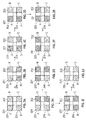
- FIGS. 2A-2J an illustrated embodiment of the inflation sequence of the inflatable tubes 201-204 is shown.
- the FIGS. 2A-2J depict a schematic representation of the inflatable tubes 201-204 disposed as shown in FIG. 1A .
- quadrant A depicts the overlapping of the inflatable tube 201 and the inflatable tube 203
- quadrant B depicts the overlapping of the inflatable tube 202 and the inflatable tube 203
- quadrant C depicts the overlapping of the inflatable tube 202 and the inflatable tube 204
- quadrant D depicts the overlapping of the inflatable tube 201 and the inflatable tube 204.
- quadrants A-D or a combination thereof can provide areas of peak interface pressure, which are depicted by cross-hatching.
- the inflation of the inflatable tubes 201-204 or a combination thereof can provide various locations of peak interface pressure as shown in FIGS. 2A-2J .
- the inflator 110 and the controller 112 can provide various locations of peak interface pressure and various sequences of shifting the peak interface pressure location. While an illustrated sequence of peak interface pressure locations is shown, the inflatable tubes 201-204 can be utilized with any suitable configuration and sequence of peak interface pressure locations.
- the inflatable tubes 201, 202, 203, and 204 are at the low pressure provided by the inflator.
- all quadrants A-D receive the peak interface pressure due to equal distribution of pressure within the inflatable tubes 201-204.
- the inflatable tube 203 is pressurized to the high pressure and inflatable tubes 201, 202, and 204 are pressurized to the low pressure.
- quadrants A and B receive the peak interface pressure due to a greater pressure within inflatable tube 203.
- the inflatable tubes 202 and 203 are pressurized at the high pressure and inflatable tubes 201 and 204 are pressurized to the low pressure.
- quadrant B receives the peak interface pressure due to a greater pressure within inflatable tubes 202 and 203, which overlap in quadrant B to form a higher pressure area.
- the inflatable tube 202 is pressurized to the high pressure and inflatable tubes 201, 203, and 204 are pressurized to the low pressure.
- quadrants B and C receive the peak interface pressure due to a greater pressure within inflatable tube 202.
- inflatable tubes 202 and 204 are pressurized to the high pressure and inflatable tubes 201 and 203 are pressurized to the low pressure.
- quadrant C receives the peak interface pressure due to a greater pressure within inflatable tubes 202 and 204, which overlap in quadrant C to form a higher pressure area.
- the inflatable tube 204 is pressurized to the high pressure and inflatable tubes 201, 202, and 203 are pressurized to the low pressure.
- quadrants C and D receive the peak interface pressure due to a greater pressure within inflatable tube 204.
- the inflatable tubes 201 and 204 are pressurized to the high pressure and inflatable tubes 202 and 203 are pressurized to the low pressure.
- quadrant D receives the peak interface pressure due to a greater pressure within inflatable tubes 201 and 204, which overlap in quadrant D to form a higher pressure area.
- the inflatable tube 201 is pressurized to the high pressure and inflatable tubes 202, 203, and 204 are pressurized to the low pressure.
- quadrants A and D receive the peak interface pressure due to a greater pressure within inflatable tube 201.
- the inflatable tubes 201 and 203 are pressurized to the high pressure and inflatable tubes 202 and 204 are pressurized to the low pressure.
- quadrant A receives the peak interface pressure due to a greater pressure within inflatable tubes 201 and 203, which overlap in quadrant A to form a higher pressure area.
- all the inflatable tubes 201, 202, 203, and 204 are pressurized to the high pressure.
- all quadrants A-D receive the peak interface pressure due to equal distribution of pressure within the inflatable tubes 201-204.
Abstract
Description
- This application claims priority from
Indian Provisional Patent Application No. 4365/CHE/2015, filed on August 20, 2015 - The subject matter disclosed herein relates to occupant support devices, and more particularly, to an apparatus and a method for providing varying interface pressure for an occupant.
- Typically, conventional occupant support devices such as seat cushions and webbing are utilized to support occupants. In some cases, conventional occupant support devices create static interface pressure points that may result in poor circulation, compression of body tissues, arthritis, inflamed tendons and sheaths, joint deterioration, muscle pain, and swelling.
- According to an embodiment, an occupant support device includes a first inflatable tube, a second inflatable tube disposed parallel to the first inflatable tube, a third inflatable tube disposed at a relative angle to the first inflatable tube, above the first inflatable tube and below the second inflatable tube, a fourth inflatable tube disposed parallel to the third inflatable tube, below the first inflatable tube and above the second inflatable tube, and an inflation device to selectively provide a low pressure and a high pressure to at least one of the first inflatable tube, the second inflatable tube, the third inflatable tube, and the fourth inflatable tube.
- According to an embodiment, a method to vary an interface pressure for an occupant support device includes providing a first inflatable tube, providing a second inflatable tube disposed parallel to the first inflatable tube, providing a third inflatable tube disposed at a relative angle to the first inflatable tube, above the first inflatable tube and below the second inflatable tube, providing a fourth inflatable tube disposed parallel to the third inflatable tube, below the first inflatable tube and above the second inflatable tube, and selectively providing a low pressure and a high pressure to at least one of the first inflatable tube, the second inflatable tube, the third inflatable tube, and the fourth inflatable tube via an inflation device.
- According to an embodiment, a seating device includes a first plurality of inflatable tubes, a second plurality of inflatable tubes disposed parallel to the first plurality of inflatable tubes, a third plurality of inflatable tubes disposed at a relative angle to the first plurality of inflatable tubes, above the first plurality of inflatable tubes and below the second plurality of inflatable tubes, a fourth plurality of inflatable tubes disposed parallel to the third plurality of inflatable tubes, below the first plurality of inflatable tubes and above the second plurality of inflatable tubes, and an inflation device to selectively provide a low pressure and a high pressure to at least one of the first plurality of inflatable tubes, the second plurality of inflatable tubes, the third plurality of inflatable tubes, and the fourth plurality of inflatable tubes.
- Technical function of the embodiments described above includes an inflation device to selectively provide a low pressure and a high pressure to a group consisting of at least one of the first inflatable tube, the second inflatable tube, the third inflatable tube, and the fourth inflatable tube.
- Other aspects, features, and techniques of the embodiments will become more apparent from the following description taken in conjunction with the drawings.
- The subject matter is particularly pointed out and distinctly claimed in the claims at the conclusion of the specification. The foregoing and other features, and advantages of the embodiments are apparent from the following detailed description taken in conjunction with the accompanying drawings in which like elements are numbered alike in the FIGURES:
-
FIG. 1A illustrates a pictorial view of one embodiment of an occupant support device; -
FIG. 1B illustrates a schematic view of one embodiment of an occupant support device; and -
FIGS.2A-2J are schematic views of various pressure distribution configurations of the occupant support device shown inFIGS. 1A and 1B . - Referring to the figures,
FIG. 1 shows anoccupant support system 100. In the illustrated embodiment, theoccupant support system 100 includes an interlacedtubing support 105, aninflator 110 and acontroller 112. Advantageously, theoccupant support system 100 can vary the location of interface pressure between the occupant and theoccupant support system 100 to increase comfort and prevent harm to an occupant, particularly during limited mobility situations. - In the illustrated embodiment, the interlaced
tubing support 105 includes a firstinflatable tubing 101, a secondinflatable tubing 102, a thirdinflatable tubing 103 and a fourthinflatable tubing 104. In the illustrated embodiment, the firstinflatable tubing 101 and the secondinflatable tubing 102 are parallel to each other and are weaved between the thirdinflatable tubing 103 and the fourthinflatable tubing 104, which are also parallel to one another. In certain embodiments, additional sets of parallel tubings could be provided. - The interlaced
tubing support 105 can be selectively inflated and deflated to provide varying locations of interface pressure for an occupant. In one embodiment, by repositioning the interface pressure points of the interlacedtubing support 105 the pressure experienced by the occupant may be varied. The interlacedtubing support 105 can be utilized in aircrafts, wheel chairs, hospital beds, automobiles, massaging seats, etc. - In the illustrated embodiment, the first
inflatable tube 101 is formed of a hollow tubular material. The firstinflatable tube 101 can be formed of a resilient material to support the weight of an occupant when formed in the interlacedtubing support 105. The firstinflatable tube 101 can be formed of elastomer, plastic, rubber, etc. The firstinflatable tube 101 can include a hollow channel therein to allow for air or any other suitable fluid to flow there through to expand or increase in firmness. In the illustrated embodiment, the firstinflatable tube 101 is part of a plurality of firstinflatable tubes 101 as shown inFIG. 1 . - In the illustrated embodiment, the second
inflatable tube 102 is formed of a hollow tubular material. The secondinflatable tube 102 can be formed of a resilient material to support the weight of an occupant when formed in the interlacedtubing support 105. The secondinflatable tube 102 can be formed of elastomer, plastic, rubber, etc. The secondinflatable tube 102 can include a hollow channel therein to allow for air or any other suitable fluid to flow there through to expand or increase in firmness. The second inflatable tube can be disposed in a direction generally parallel to the firstinflatable tube 101. In the illustrated embodiment, the secondinflatable tube 102 is part of a plurality of secondinflatable tubes 102 as shown inFIG. 1 . - In the illustrated embodiment, the third
inflatable tube 103 is formed of a hollow tubular material. The thirdinflatable tube 103 can be formed of a resilient material to support the weight of an occupant when formed in the interlacedtubing support 105. The thirdinflatable tube 103 can be formed of elastomer, plastic, rubber, etc. The thirdinflatable tube 103 can include a hollow channel therein to allow for air or any other suitable fluid to flow there through to expand or increase in firmness. The third inflatable tube can be disposed generally at an angle relative to the firstinflatable tube 101. In the illustrated embodiment, the relative angle is approximately 90 degrees or otherwise perpendicular to the firstinflatable tube 101 and, by extension, the secondinflatable tube 102. In the illustrated embodiment, the thirdinflatable tube 103 is part of a plurality of thirdinflatable tubes 103 as shown inFIG. 1 . - In the illustrated embodiment, the fourth
inflatable tube 104 is formed of a hollow tubular material. The fourthinflatable tube 104 can be formed of a resilient material to support the weight of an occupant when formed in the interlacedtubing support 105. The fourthinflatable tube 104 can be formed of elastomer, plastic, rubber, etc. The fourthinflatable tube 104 can include a hollow channel therein to allow for air or any other suitable fluid to flow there through to expand or increase in firmness. The fourth inflatable tube can be disposed generally parallel to the thirdinflatable tube 103. In the illustrated embodiment, the fourthinflatable tube 104 is part of a plurality of fourthinflatable tubes 104 as shown inFIG. 1 . - As shown in
FIG. 1A , theinflatable tubes tubing support 105. In the illustrated embodiment, the firstinflatable tube 101 is adjacent to the secondinflatable tube 102. Further, the thirdinflatable tube 103 is adjacent to the fourthinflatable tube 104. In the illustrated embodiment, the inflatable tubes 101-104 can be disposed in a repeating pattern. In the illustrated embodiment, the firstinflatable tube 101 is woven such that the firstinflatable tube 101 goes below the thirdinflatable tube 103 and above the fourthinflatable tube 104. Similarly, the secondinflatable tube 102 is woven such that the secondinflatable tube 102 is disposed above the thirdinflatable tube 103 and below the fourthinflatable tube 104. The inflatable tubes 101-104 form a lattice that can support an occupant. In certain embodiments, the interlacedtubing support 105 can provide adequate occupant support in the absence of air or fluid pressure there through. - In the illustrated embodiment, due to the interlaced structure of the interlaced
tubing support 105, interface pressure peaks between the interlacedtubing support 105 and the occupant can be localized and dynamically shifted by selectively inflating inflatable tubes 101-104 in a desired order. Advantageously, interface pressure locations experienced by an occupant can be continuously or periodically changed at intervals. - Referring to
FIG. 1B , in an illustrated embodiment, afoam cushion 120 can be disposed above the interlacedtubing support 105 for increased occupant comfort. Thefoam cushion 120 can allow for occupant comfort in addition to the dynamic interface pressure locations provided by interlacedtubing support 105. - Referring to
FIGS. 1A and 1B , aninflator 110 and acontroller 112 are shown. In the illustrated embodiment, theinflator 110 is in fluid communication with theinflatable tubes tubing support 105. In the illustrated embodiment, the inflator 110 can provide a low pressure and a high pressure to theinflatable tubes tubing support 105. In certain embodiments, the high pressure and the low pressure can be any suitable pressures contingent on occupant parameters, inflatable tube 101-104 characteristics, etc. In certain embodiments, the inflator 110 can utilize compressor bleed air, a dedicated compressor, air pump etc. - In the illustrated embodiment, the
controller 112 can receive interface pressure measurements, flight information, occupant parameters, etc. to command theinflator 110 to selectively provide high and low pressures to theinflatable tubes tubing support 105. Advantageously, the controlled application of a high and low pressure to inflatable tubes 101-104 can provide occupant comfort, while minimizing compression of occupant muscle tissues, prevent edema, etc. - Referring to
FIGS. 2A-2J an illustrated embodiment of the inflation sequence of the inflatable tubes 201-204 is shown. TheFIGS. 2A-2J depict a schematic representation of the inflatable tubes 201-204 disposed as shown inFIG. 1A . In theFIGS. 2A-2J , quadrant A depicts the overlapping of theinflatable tube 201 and theinflatable tube 203, quadrant B depicts the overlapping of theinflatable tube 202 and theinflatable tube 203, quadrant C depicts the overlapping of theinflatable tube 202 and theinflatable tube 204, and quadrant D depicts the overlapping of theinflatable tube 201 and theinflatable tube 204. - In the illustrated embodiment, quadrants A-D or a combination thereof can provide areas of peak interface pressure, which are depicted by cross-hatching. In the illustrated embodiment, the inflation of the inflatable tubes 201-204 or a combination thereof can provide various locations of peak interface pressure as shown in
FIGS. 2A-2J . In certain embodiments, theinflator 110 and thecontroller 112 can provide various locations of peak interface pressure and various sequences of shifting the peak interface pressure location. While an illustrated sequence of peak interface pressure locations is shown, the inflatable tubes 201-204 can be utilized with any suitable configuration and sequence of peak interface pressure locations. - In
FIG. 2A theinflatable tubes - In
FIG. 2B theinflatable tube 203 is pressurized to the high pressure andinflatable tubes inflatable tube 203. - In
FIG. 2C , theinflatable tubes inflatable tubes inflatable tubes - In
FIG. 2D , theinflatable tube 202 is pressurized to the high pressure andinflatable tubes inflatable tube 202. - In
FIG. 2E ,inflatable tubes inflatable tubes inflatable tubes - In
FIG. 2F , theinflatable tube 204 is pressurized to the high pressure andinflatable tubes inflatable tube 204. - In
FIG. 2G , theinflatable tubes inflatable tubes inflatable tubes - In
FIG. 2H , theinflatable tube 201 is pressurized to the high pressure andinflatable tubes inflatable tube 201. - In
FIG. 2I , theinflatable tubes inflatable tubes inflatable tubes - In
FIG. 2J all theinflatable tubes - The terminology used herein is for the purpose of describing particular embodiments only and is not intended to be limiting of the embodiments. While the description of the present embodiments has been presented for purposes of illustration and description, it is not intended to be exhaustive or limited to the embodiments in the form disclosed. Many modifications, variations, alterations, substitutions or equivalent arrangement not hereto described will be apparent to those of ordinary skill in the art without departing from the scope and spirit of the embodiments. Additionally, while various embodiments have been described, it is to be understood that aspects may include only some of the described embodiments. Accordingly, the embodiments are not to be seen as limited by the foregoing description, but are only limited by the scope of the appended claims.
Claims (15)
- An occupant support device, comprising:a first inflatable tube (141);a second inflatable tube (102) disposed parallel to the first inflatable tube (101);a third inflatable tube (103) disposed at a relative angle to the first inflatable tube (101), above the first inflatable tube (101) and below the second inflatable tube (102);a fourth inflatable tube (104) disposed parallel to the third inflatable tube (103), below the first inflatable tube (101) and above the second inflatable tube (102); andan inflation device to selectively provide a low pressure and a high pressure to at least one of the first inflatable tube (101), the second inflatable tube (102), the third inflatable tube (103), and the fourth inflatable tube (104).
- The occupant support device of claim 1, wherein the third inflatable tube (103) is disposed perpendicular to the first inflatable tube (101).
- The occupant support device of claims 1 or 2, further comprising a foam cushion (120) supported by the first inflatable tube (101), the second inflatable tube (102), the third inflatable tube (103), and the fourth inflatable tube (104).
- The occupant support device of claim 1, wherein the inflation device continuously selectively provides the low pressure and the high pressure to the group consisting of at least one of the first inflatable tube (101), the second inflatable tube (102), the third inflatable tube (103), and the fourth inflatable tube (104).
- The occupant support device of claim 1, wherein the inflation device selectively provides the low pressure and the high pressure at a predetermined interval to the group consisting of at least one of the first inflatable tube (101), the second inflatable tube (102), the third inflatable tube (103), and the fourth inflatable tube (104).
- A method to vary an interface pressure for an occupant support device, comprising:providing a first inflatable tube (101);providing a second inflatable tube (102) disposed parallel to the first inflatable tube (101);providing a third inflatable tube (103) disposed at a relative angle to the first inflatable tube (101), above the first inflatable tube (101) and below the second inflatable tube (102);providing a fourth inflatable tube (104) disposed parallel to the third inflatable tube (103), below the first inflatable tube (101) and above the second inflatable tube (102); andselectively providing a low pressure and a high pressure to at least one of the first inflatable tube (101), the second inflatable tube (102), the third inflatable tube (103), and the fourth inflatable tube (104) via an inflation device.
- The method of claim 6, further comprising providing the low pressure to the first inflatable tube (101), the second inflatable tube (102), the third inflatable tube (103), and the fourth inflatable tube (104) via the inflation device.
- The method of claim 6, further comprising providing the low pressure to the first inflatable tube (101), the second inflatable tube (102) and the fourth inflatable tube (104) via the inflation device and providing the high pressure to the third inflatable tube (103) via the inflation device.
- The method of claim 6, further comprising providing the low pressure to the first inflatable tube (101) and the fourth inflatable tube (104) via the inflation device and providing the high pressure to the third inflatable tube (103) and the second inflatable tube (102) via the inflation device.
- The method of claim 6, further comprising providing the low pressure to the first inflatable tube (101), the third inflatable tube (103), the fourth inflatable tube (104) via the inflation device and providing the high pressure to the second inflatable tube (102) via the inflation device.
- The method of claim 6, further comprising providing the low pressure to the first inflatable tube (101) and the third inflatable tube (103) via the inflation device and providing the high pressure to the second inflatable tube (102) and the fourth inflatable tube (104) via the inflation device.
- The method of claim 6, further comprising providing the low pressure to the first inflatable tube (101), the second inflatable tube (102) and the third inflatable tube (103) via the inflation device and providing the high pressure to the fourth inflatable tube (104) via the inflation device.
- The method of claim 6, further comprising providing the low pressure to the second inflatable tube (102) and the third inflatable tube (103) via the inflation device and providing the high pressure to the first inflatable tube (101) and the fourth inflatable tube (104) via the inflation device.
- The method of claim 6, further comprising providing the low pressure to the second inflatable tube (102), the third inflatable tube (103) and the fourth inflatable tube (104) via the inflation device and providing the high pressure to the first inflatable tube (101) via the inflation device.
- The method of claim 6, further comprising providing the low pressure to the second inflatable tube (102) and the fourth inflatable tube (104) via the inflation device and providing the high pressure to the first inflatable tube (101) and the third inflatable tube (103) via the inflation device.
Applications Claiming Priority (1)
| Application Number | Priority Date | Filing Date | Title |
|---|---|---|---|
| IN4365CH2015 | 2015-08-20 |
Publications (2)
| Publication Number | Publication Date |
|---|---|
| EP3138729A1 true EP3138729A1 (en) | 2017-03-08 |
| EP3138729B1 EP3138729B1 (en) | 2019-04-17 |
Family
ID=56799298
Family Applications (1)
| Application Number | Title | Priority Date | Filing Date |
|---|---|---|---|
| EP16185138.1A Active EP3138729B1 (en) | 2015-08-20 | 2016-08-22 | Adjustable interface pressure device |
Country Status (5)
| Country | Link |
|---|---|
| US (1) | US9615669B2 (en) |
| EP (1) | EP3138729B1 (en) |
| CN (1) | CN106467043B (en) |
| BR (1) | BR102016018999A2 (en) |
| CA (1) | CA2939712C (en) |
Families Citing this family (1)
| Publication number | Priority date | Publication date | Assignee | Title |
|---|---|---|---|---|
| JP6985586B2 (en) * | 2017-03-28 | 2021-12-22 | テイ・エス テック株式会社 | Vehicle seat |
Citations (4)
| Publication number | Priority date | Publication date | Assignee | Title |
|---|---|---|---|---|
| US3674019A (en) * | 1970-10-23 | 1972-07-04 | Grant Airmass Corp | Dual layer cellular inflatable pad |
| US4840425A (en) * | 1987-04-21 | 1989-06-20 | Tush Cush, Inc. | Varying support cushioned seating assembly and method |
| WO2000003625A2 (en) * | 1998-07-14 | 2000-01-27 | Maricevic Zdravko | Universal mattress for sitting, laying, decubitus prevention and curing |
| WO2015083603A1 (en) * | 2013-12-06 | 2015-06-11 | アイシン精機 株式会社 | Seat device |
Family Cites Families (26)
| Publication number | Priority date | Publication date | Assignee | Title |
|---|---|---|---|---|
| US2691179A (en) * | 1951-05-25 | 1954-10-12 | Englander Co Inc | Pneumatic structure for mattresses, seat and back cushions, and the like |
| US3680918A (en) * | 1970-10-26 | 1972-08-01 | Donald L Briggs | Air cushion and seat frame |
| US4255824A (en) * | 1979-06-07 | 1981-03-17 | Samuel Pertchik | Cushion for decubitus ulcers |
| US5303977A (en) * | 1986-04-02 | 1994-04-19 | Sereboff Joel L | Fluid cushion system |
| US4803744A (en) * | 1987-05-19 | 1989-02-14 | Hill-Rom Company, Inc. | Inflatable bed |
| US5044030A (en) * | 1990-06-06 | 1991-09-03 | Fabrico Manufacturing Corporation | Multiple layer fluid-containing cushion |
| CA2051275C (en) * | 1991-09-12 | 1999-01-05 | Elias A. M. Hendi | Hydropneumatic matress |
| GB9311069D0 (en) * | 1993-05-23 | 1993-07-14 | British Astec Medical | Alternating pressure pad |
| US5509155A (en) * | 1994-08-04 | 1996-04-23 | Creative Medical, Inc. | Alternating low air loss pressure overlay for patient bedside chair |
| US6212719B1 (en) * | 1997-10-10 | 2001-04-10 | D2Rm Corp. | Air massager cushioning device |
| US6551450B1 (en) * | 1997-10-10 | 2003-04-22 | D2Rm Corp. | Unique air and sonic massaging apparatus |
| FR2788595B1 (en) * | 1999-01-15 | 2001-04-27 | Soprolia | MEASURING APPARATUS AND INSTALLATION FOR ESTABLISHING A COMPARISON BETWEEN DIFFERENT TYPES OF COMFORT CONCERNING FAMILIES OF BEDDING PRODUCTS OR SEATS, TAKING INTO ACCOUNT THE WEIGHT AND THE MORPHOLOGY OF THE USER |
| US6467106B1 (en) * | 1999-06-14 | 2002-10-22 | Hill-Rom Services, Inc. | Patient transfer apparatus |
| US6502263B1 (en) * | 2001-07-26 | 2003-01-07 | Invacare Corporation | Seat cushion and positioning assembly including inflatable air cell pressure compensation insert |
| DE10232627A1 (en) | 2002-07-18 | 2004-01-29 | Prospective Concepts Ag | Adaptive pneumatic seat and backrest cushion for vehicles and airplanes |
| DE10232625A1 (en) * | 2002-07-18 | 2004-01-29 | Prospective Concepts Ag | Adaptive pneumatic seat and backrest cushion for vehicles and airplanes |
| DE20305023U1 (en) * | 2003-03-12 | 2003-07-03 | Thomas Gmbh & Co Technik Innovation Kg | Underlay for a human body, in particular, mattress for beds, loungers, armchairs and the like comprises a core with at least one layer of elastic tubes |
| ATE470377T1 (en) * | 2005-07-20 | 2010-06-15 | Prospective Concepts Ag | PNEUMATIC VEHICLE SEAT |
| US7441294B2 (en) * | 2007-01-22 | 2008-10-28 | L&P Property Management Company | Bedding or seating product having inflatable concentric air bladders |
| FR2917278A1 (en) * | 2007-06-18 | 2008-12-19 | Hill Rom Ind S A Sa | MATTRESS-TYPE SUPPORT DEVICE HAVING A HETEROGENEUS INFLATABLE STRUCTURE |
| FR2922427B1 (en) * | 2007-10-18 | 2013-03-29 | Hill Rom Ind Sa | INFLATABLE CELL, MANUFACTURING METHOD AND SUPPORTING DEVICE HAVING THE SAME |
| DE112010004064T5 (en) * | 2009-12-02 | 2012-12-27 | Faurecia Automotive Seating, Inc. | VEHICLE SEAT CUSHION WITH VENTILATORY SUPPORT |
| US8147000B1 (en) | 2010-05-11 | 2012-04-03 | Drake Terry G | Variable-pressure lumbar and back support cushion |
| US8678511B2 (en) | 2011-02-01 | 2014-03-25 | Vinod M. Grover | Adjustable automobile air cushion apparatus |
| CN203524902U (en) * | 2013-11-01 | 2014-04-09 | 贵族实业股份有限公司 | Air bed with body turning and body twisting function |
| CN204236284U (en) * | 2014-10-24 | 2015-04-01 | 苏州中航中振汽车饰件有限公司 | With the automotive seat of circulating gas-bag group |
-
2015
- 2015-10-16 US US14/885,026 patent/US9615669B2/en active Active
-
2016
- 2016-08-17 BR BR102016018999-3A patent/BR102016018999A2/en not_active Application Discontinuation
- 2016-08-19 CA CA2939712A patent/CA2939712C/en active Active
- 2016-08-19 CN CN201610696183.4A patent/CN106467043B/en active Active
- 2016-08-22 EP EP16185138.1A patent/EP3138729B1/en active Active
Patent Citations (4)
| Publication number | Priority date | Publication date | Assignee | Title |
|---|---|---|---|---|
| US3674019A (en) * | 1970-10-23 | 1972-07-04 | Grant Airmass Corp | Dual layer cellular inflatable pad |
| US4840425A (en) * | 1987-04-21 | 1989-06-20 | Tush Cush, Inc. | Varying support cushioned seating assembly and method |
| WO2000003625A2 (en) * | 1998-07-14 | 2000-01-27 | Maricevic Zdravko | Universal mattress for sitting, laying, decubitus prevention and curing |
| WO2015083603A1 (en) * | 2013-12-06 | 2015-06-11 | アイシン精機 株式会社 | Seat device |
Also Published As
| Publication number | Publication date |
|---|---|
| EP3138729B1 (en) | 2019-04-17 |
| CA2939712C (en) | 2023-10-24 |
| CN106467043A (en) | 2017-03-01 |
| CA2939712A1 (en) | 2017-02-20 |
| BR102016018999A2 (en) | 2017-07-25 |
| CN106467043B (en) | 2021-03-02 |
| US20170049244A1 (en) | 2017-02-23 |
| US9615669B2 (en) | 2017-04-11 |
Similar Documents
| Publication | Publication Date | Title |
|---|---|---|
| US10569678B2 (en) | Thoracic air bladder assembly | |
| CN105857135B (en) | Vehicle seat with muscle massage system | |
| US20170079872A1 (en) | Adjustable seat assembly | |
| US9949568B2 (en) | Pelvic and sacral bladder assembly | |
| EP1447070A1 (en) | Seat with massaging apparatus and process for performing a massage | |
| US10085565B2 (en) | Sacral air bladder assembly | |
| US20140265491A1 (en) | Thoracic region comfort vehicle seating system with pneumatic adjustment | |
| US10144318B2 (en) | Seat device | |
| US10300824B2 (en) | Vehicle seat with an adjustable seat base and method for adjusting an adjustable seat base | |
| EP3058851A1 (en) | Thoracic region comfort seating system | |
| CN106080278A (en) | Support means for children's seat | |
| CN110662459A (en) | Improved liner | |
| US20160183690A1 (en) | Seating apparatus with adjustable cushioning | |
| WO2018102684A1 (en) | Variable stiffness apparatuses using an interconnected dual layer fluid-filled cell array | |
| EP3159264B1 (en) | Pressure control system and method for an aircraft seat | |
| EP3138729B1 (en) | Adjustable interface pressure device | |
| JP2014083916A (en) | Vehicle sheet | |
| EP3171736B1 (en) | Therapeutic mattress with low volume bladders | |
| CN214231666U (en) | Neck support | |
| EP4234199A3 (en) | Seating apparatus | |
| GB2144984A (en) | Seat with variable support | |
| EP3925825A1 (en) | Vehicle for public transport comprising a health system for passengers | |
| CN215502053U (en) | Hardness-adjustable seat | |
| JP6389857B2 (en) | Mattress device and bed device |
Legal Events
| Date | Code | Title | Description |
|---|---|---|---|
| PUAI | Public reference made under article 153(3) epc to a published international application that has entered the european phase |
Free format text: ORIGINAL CODE: 0009012 |
|
| STAA | Information on the status of an ep patent application or granted ep patent |
Free format text: STATUS: THE APPLICATION HAS BEEN PUBLISHED |
|
| AK | Designated contracting states |
Kind code of ref document: A1 Designated state(s): AL AT BE BG CH CY CZ DE DK EE ES FI FR GB GR HR HU IE IS IT LI LT LU LV MC MK MT NL NO PL PT RO RS SE SI SK SM TR |
|
| AX | Request for extension of the european patent |
Extension state: BA ME |
|
| RAP1 | Party data changed (applicant data changed or rights of an application transferred) |
Owner name: AMI INDUSTRIES, INC. |
|
| STAA | Information on the status of an ep patent application or granted ep patent |
Free format text: STATUS: REQUEST FOR EXAMINATION WAS MADE |
|
| 17P | Request for examination filed |
Effective date: 20170829 |
|
| RBV | Designated contracting states (corrected) |
Designated state(s): AL AT BE BG CH CY CZ DE DK EE ES FI FR GB GR HR HU IE IS IT LI LT LU LV MC MK MT NL NO PL PT RO RS SE SI SK SM TR |
|
| REG | Reference to a national code |
Ref country code: DE Ref legal event code: R079 Ref document number: 602016012472 Country of ref document: DE Free format text: PREVIOUS MAIN CLASS: B60N0002440000 Ipc: B60N0002900000 |
|
| RIC1 | Information provided on ipc code assigned before grant |
Ipc: B60N 2/90 20180101AFI20180905BHEP |
|
| GRAP | Despatch of communication of intention to grant a patent |
Free format text: ORIGINAL CODE: EPIDOSNIGR1 |
|
| STAA | Information on the status of an ep patent application or granted ep patent |
Free format text: STATUS: GRANT OF PATENT IS INTENDED |
|
| INTG | Intention to grant announced |
Effective date: 20181109 |
|
| RIC1 | Information provided on ipc code assigned before grant |
Ipc: B60N 2/90 20180101AFI20180905BHEP |
|
| GRAS | Grant fee paid |
Free format text: ORIGINAL CODE: EPIDOSNIGR3 |
|
| GRAA | (expected) grant |
Free format text: ORIGINAL CODE: 0009210 |
|
| STAA | Information on the status of an ep patent application or granted ep patent |
Free format text: STATUS: THE PATENT HAS BEEN GRANTED |
|
| AK | Designated contracting states |
Kind code of ref document: B1 Designated state(s): AL AT BE BG CH CY CZ DE DK EE ES FI FR GB GR HR HU IE IS IT LI LT LU LV MC MK MT NL NO PL PT RO RS SE SI SK SM TR |
|
| REG | Reference to a national code |
Ref country code: GB Ref legal event code: FG4D |
|
| REG | Reference to a national code |
Ref country code: CH Ref legal event code: EP |
|
| REG | Reference to a national code |
Ref country code: DE Ref legal event code: R096 Ref document number: 602016012472 Country of ref document: DE |
|
| REG | Reference to a national code |
Ref country code: AT Ref legal event code: REF Ref document number: 1121171 Country of ref document: AT Kind code of ref document: T Effective date: 20190515 Ref country code: IE Ref legal event code: FG4D |
|
| REG | Reference to a national code |
Ref country code: NL Ref legal event code: MP Effective date: 20190417 |
|
| REG | Reference to a national code |
Ref country code: LT Ref legal event code: MG4D |
|
| PG25 | Lapsed in a contracting state [announced via postgrant information from national office to epo] |
Ref country code: NL Free format text: LAPSE BECAUSE OF FAILURE TO SUBMIT A TRANSLATION OF THE DESCRIPTION OR TO PAY THE FEE WITHIN THE PRESCRIBED TIME-LIMIT Effective date: 20190417 |
|
| PG25 | Lapsed in a contracting state [announced via postgrant information from national office to epo] |
Ref country code: NO Free format text: LAPSE BECAUSE OF FAILURE TO SUBMIT A TRANSLATION OF THE DESCRIPTION OR TO PAY THE FEE WITHIN THE PRESCRIBED TIME-LIMIT Effective date: 20190717 Ref country code: FI Free format text: LAPSE BECAUSE OF FAILURE TO SUBMIT A TRANSLATION OF THE DESCRIPTION OR TO PAY THE FEE WITHIN THE PRESCRIBED TIME-LIMIT Effective date: 20190417 Ref country code: LT Free format text: LAPSE BECAUSE OF FAILURE TO SUBMIT A TRANSLATION OF THE DESCRIPTION OR TO PAY THE FEE WITHIN THE PRESCRIBED TIME-LIMIT Effective date: 20190417 Ref country code: HR Free format text: LAPSE BECAUSE OF FAILURE TO SUBMIT A TRANSLATION OF THE DESCRIPTION OR TO PAY THE FEE WITHIN THE PRESCRIBED TIME-LIMIT Effective date: 20190417 Ref country code: PT Free format text: LAPSE BECAUSE OF FAILURE TO SUBMIT A TRANSLATION OF THE DESCRIPTION OR TO PAY THE FEE WITHIN THE PRESCRIBED TIME-LIMIT Effective date: 20190817 Ref country code: ES Free format text: LAPSE BECAUSE OF FAILURE TO SUBMIT A TRANSLATION OF THE DESCRIPTION OR TO PAY THE FEE WITHIN THE PRESCRIBED TIME-LIMIT Effective date: 20190417 Ref country code: AL Free format text: LAPSE BECAUSE OF FAILURE TO SUBMIT A TRANSLATION OF THE DESCRIPTION OR TO PAY THE FEE WITHIN THE PRESCRIBED TIME-LIMIT Effective date: 20190417 Ref country code: SE Free format text: LAPSE BECAUSE OF FAILURE TO SUBMIT A TRANSLATION OF THE DESCRIPTION OR TO PAY THE FEE WITHIN THE PRESCRIBED TIME-LIMIT Effective date: 20190417 |
|
| PG25 | Lapsed in a contracting state [announced via postgrant information from national office to epo] |
Ref country code: BG Free format text: LAPSE BECAUSE OF FAILURE TO SUBMIT A TRANSLATION OF THE DESCRIPTION OR TO PAY THE FEE WITHIN THE PRESCRIBED TIME-LIMIT Effective date: 20190717 Ref country code: LV Free format text: LAPSE BECAUSE OF FAILURE TO SUBMIT A TRANSLATION OF THE DESCRIPTION OR TO PAY THE FEE WITHIN THE PRESCRIBED TIME-LIMIT Effective date: 20190417 Ref country code: PL Free format text: LAPSE BECAUSE OF FAILURE TO SUBMIT A TRANSLATION OF THE DESCRIPTION OR TO PAY THE FEE WITHIN THE PRESCRIBED TIME-LIMIT Effective date: 20190417 Ref country code: RS Free format text: LAPSE BECAUSE OF FAILURE TO SUBMIT A TRANSLATION OF THE DESCRIPTION OR TO PAY THE FEE WITHIN THE PRESCRIBED TIME-LIMIT Effective date: 20190417 Ref country code: GR Free format text: LAPSE BECAUSE OF FAILURE TO SUBMIT A TRANSLATION OF THE DESCRIPTION OR TO PAY THE FEE WITHIN THE PRESCRIBED TIME-LIMIT Effective date: 20190718 |
|
| REG | Reference to a national code |
Ref country code: AT Ref legal event code: MK05 Ref document number: 1121171 Country of ref document: AT Kind code of ref document: T Effective date: 20190417 |
|
| PG25 | Lapsed in a contracting state [announced via postgrant information from national office to epo] |
Ref country code: IS Free format text: LAPSE BECAUSE OF FAILURE TO SUBMIT A TRANSLATION OF THE DESCRIPTION OR TO PAY THE FEE WITHIN THE PRESCRIBED TIME-LIMIT Effective date: 20190817 |
|
| REG | Reference to a national code |
Ref country code: DE Ref legal event code: R097 Ref document number: 602016012472 Country of ref document: DE |
|
| PG25 | Lapsed in a contracting state [announced via postgrant information from national office to epo] |
Ref country code: SK Free format text: LAPSE BECAUSE OF FAILURE TO SUBMIT A TRANSLATION OF THE DESCRIPTION OR TO PAY THE FEE WITHIN THE PRESCRIBED TIME-LIMIT Effective date: 20190417 Ref country code: AT Free format text: LAPSE BECAUSE OF FAILURE TO SUBMIT A TRANSLATION OF THE DESCRIPTION OR TO PAY THE FEE WITHIN THE PRESCRIBED TIME-LIMIT Effective date: 20190417 Ref country code: DK Free format text: LAPSE BECAUSE OF FAILURE TO SUBMIT A TRANSLATION OF THE DESCRIPTION OR TO PAY THE FEE WITHIN THE PRESCRIBED TIME-LIMIT Effective date: 20190417 Ref country code: EE Free format text: LAPSE BECAUSE OF FAILURE TO SUBMIT A TRANSLATION OF THE DESCRIPTION OR TO PAY THE FEE WITHIN THE PRESCRIBED TIME-LIMIT Effective date: 20190417 Ref country code: CZ Free format text: LAPSE BECAUSE OF FAILURE TO SUBMIT A TRANSLATION OF THE DESCRIPTION OR TO PAY THE FEE WITHIN THE PRESCRIBED TIME-LIMIT Effective date: 20190417 Ref country code: RO Free format text: LAPSE BECAUSE OF FAILURE TO SUBMIT A TRANSLATION OF THE DESCRIPTION OR TO PAY THE FEE WITHIN THE PRESCRIBED TIME-LIMIT Effective date: 20190417 |
|
| PLBE | No opposition filed within time limit |
Free format text: ORIGINAL CODE: 0009261 |
|
| STAA | Information on the status of an ep patent application or granted ep patent |
Free format text: STATUS: NO OPPOSITION FILED WITHIN TIME LIMIT |
|
| PG25 | Lapsed in a contracting state [announced via postgrant information from national office to epo] |
Ref country code: IT Free format text: LAPSE BECAUSE OF FAILURE TO SUBMIT A TRANSLATION OF THE DESCRIPTION OR TO PAY THE FEE WITHIN THE PRESCRIBED TIME-LIMIT Effective date: 20190417 Ref country code: SM Free format text: LAPSE BECAUSE OF FAILURE TO SUBMIT A TRANSLATION OF THE DESCRIPTION OR TO PAY THE FEE WITHIN THE PRESCRIBED TIME-LIMIT Effective date: 20190417 |
|
| 26N | No opposition filed |
Effective date: 20200120 |
|
| PG25 | Lapsed in a contracting state [announced via postgrant information from national office to epo] |
Ref country code: TR Free format text: LAPSE BECAUSE OF FAILURE TO SUBMIT A TRANSLATION OF THE DESCRIPTION OR TO PAY THE FEE WITHIN THE PRESCRIBED TIME-LIMIT Effective date: 20190417 |
|
| PG25 | Lapsed in a contracting state [announced via postgrant information from national office to epo] |
Ref country code: LI Free format text: LAPSE BECAUSE OF NON-PAYMENT OF DUE FEES Effective date: 20190831 Ref country code: CH Free format text: LAPSE BECAUSE OF NON-PAYMENT OF DUE FEES Effective date: 20190831 Ref country code: MC Free format text: LAPSE BECAUSE OF FAILURE TO SUBMIT A TRANSLATION OF THE DESCRIPTION OR TO PAY THE FEE WITHIN THE PRESCRIBED TIME-LIMIT Effective date: 20190417 Ref country code: SI Free format text: LAPSE BECAUSE OF FAILURE TO SUBMIT A TRANSLATION OF THE DESCRIPTION OR TO PAY THE FEE WITHIN THE PRESCRIBED TIME-LIMIT Effective date: 20190417 Ref country code: LU Free format text: LAPSE BECAUSE OF NON-PAYMENT OF DUE FEES Effective date: 20190822 |
|
| REG | Reference to a national code |
Ref country code: BE Ref legal event code: MM Effective date: 20190831 |
|
| PG25 | Lapsed in a contracting state [announced via postgrant information from national office to epo] |
Ref country code: IE Free format text: LAPSE BECAUSE OF NON-PAYMENT OF DUE FEES Effective date: 20190822 |
|
| PG25 | Lapsed in a contracting state [announced via postgrant information from national office to epo] |
Ref country code: BE Free format text: LAPSE BECAUSE OF NON-PAYMENT OF DUE FEES Effective date: 20190831 |
|
| PG25 | Lapsed in a contracting state [announced via postgrant information from national office to epo] |
Ref country code: CY Free format text: LAPSE BECAUSE OF FAILURE TO SUBMIT A TRANSLATION OF THE DESCRIPTION OR TO PAY THE FEE WITHIN THE PRESCRIBED TIME-LIMIT Effective date: 20190417 |
|
| PG25 | Lapsed in a contracting state [announced via postgrant information from national office to epo] |
Ref country code: HU Free format text: LAPSE BECAUSE OF FAILURE TO SUBMIT A TRANSLATION OF THE DESCRIPTION OR TO PAY THE FEE WITHIN THE PRESCRIBED TIME-LIMIT; INVALID AB INITIO Effective date: 20160822 Ref country code: MT Free format text: LAPSE BECAUSE OF FAILURE TO SUBMIT A TRANSLATION OF THE DESCRIPTION OR TO PAY THE FEE WITHIN THE PRESCRIBED TIME-LIMIT Effective date: 20190417 |
|
| PG25 | Lapsed in a contracting state [announced via postgrant information from national office to epo] |
Ref country code: MK Free format text: LAPSE BECAUSE OF FAILURE TO SUBMIT A TRANSLATION OF THE DESCRIPTION OR TO PAY THE FEE WITHIN THE PRESCRIBED TIME-LIMIT Effective date: 20190417 |
|
| P01 | Opt-out of the competence of the unified patent court (upc) registered |
Effective date: 20230521 |
|
| PGFP | Annual fee paid to national office [announced via postgrant information from national office to epo] |
Ref country code: GB Payment date: 20230720 Year of fee payment: 8 |
|
| PGFP | Annual fee paid to national office [announced via postgrant information from national office to epo] |
Ref country code: FR Payment date: 20230720 Year of fee payment: 8 Ref country code: DE Payment date: 20230720 Year of fee payment: 8 |