EP3085491A1 - Device for grinding and deburring of a planar workpiece - Google Patents
Device for grinding and deburring of a planar workpiece Download PDFInfo
- Publication number
- EP3085491A1 EP3085491A1 EP15165026.4A EP15165026A EP3085491A1 EP 3085491 A1 EP3085491 A1 EP 3085491A1 EP 15165026 A EP15165026 A EP 15165026A EP 3085491 A1 EP3085491 A1 EP 3085491A1
- Authority
- EP
- European Patent Office
- Prior art keywords
- grinding roller
- drive shaft
- drive
- belt
- control cylinder
- Prior art date
- Legal status (The legal status is an assumption and is not a legal conclusion. Google has not performed a legal analysis and makes no representation as to the accuracy of the status listed.)
- Granted
Links
Images

Classifications
-
- B—PERFORMING OPERATIONS; TRANSPORTING
- B24—GRINDING; POLISHING
- B24B—MACHINES, DEVICES, OR PROCESSES FOR GRINDING OR POLISHING; DRESSING OR CONDITIONING OF ABRADING SURFACES; FEEDING OF GRINDING, POLISHING, OR LAPPING AGENTS
- B24B7/00—Machines or devices designed for grinding plane surfaces on work, including polishing plane glass surfaces; Accessories therefor
- B24B7/10—Single-purpose machines or devices
- B24B7/12—Single-purpose machines or devices for grinding travelling elongated stock, e.g. strip-shaped work
-
- B—PERFORMING OPERATIONS; TRANSPORTING
- B24—GRINDING; POLISHING
- B24B—MACHINES, DEVICES, OR PROCESSES FOR GRINDING OR POLISHING; DRESSING OR CONDITIONING OF ABRADING SURFACES; FEEDING OF GRINDING, POLISHING, OR LAPPING AGENTS
- B24B9/00—Machines or devices designed for grinding edges or bevels on work or for removing burrs; Accessories therefor
- B24B9/02—Machines or devices designed for grinding edges or bevels on work or for removing burrs; Accessories therefor characterised by a special design with respect to properties of materials specific to articles to be ground
- B24B9/04—Machines or devices designed for grinding edges or bevels on work or for removing burrs; Accessories therefor characterised by a special design with respect to properties of materials specific to articles to be ground of metal, e.g. skate blades
-
- B—PERFORMING OPERATIONS; TRANSPORTING
- B24—GRINDING; POLISHING
- B24B—MACHINES, DEVICES, OR PROCESSES FOR GRINDING OR POLISHING; DRESSING OR CONDITIONING OF ABRADING SURFACES; FEEDING OF GRINDING, POLISHING, OR LAPPING AGENTS
- B24B27/00—Other grinding machines or devices
- B24B27/033—Other grinding machines or devices for grinding a surface for cleaning purposes, e.g. for descaling or for grinding off flaws in the surface
-
- B—PERFORMING OPERATIONS; TRANSPORTING
- B24—GRINDING; POLISHING
- B24B—MACHINES, DEVICES, OR PROCESSES FOR GRINDING OR POLISHING; DRESSING OR CONDITIONING OF ABRADING SURFACES; FEEDING OF GRINDING, POLISHING, OR LAPPING AGENTS
- B24B41/00—Component parts such as frames, beds, carriages, headstocks
- B24B41/002—Grinding heads
-
- B—PERFORMING OPERATIONS; TRANSPORTING
- B24—GRINDING; POLISHING
- B24B—MACHINES, DEVICES, OR PROCESSES FOR GRINDING OR POLISHING; DRESSING OR CONDITIONING OF ABRADING SURFACES; FEEDING OF GRINDING, POLISHING, OR LAPPING AGENTS
- B24B41/00—Component parts such as frames, beds, carriages, headstocks
- B24B41/04—Headstocks; Working-spindles; Features relating thereto
-
- B—PERFORMING OPERATIONS; TRANSPORTING
- B24—GRINDING; POLISHING
- B24B—MACHINES, DEVICES, OR PROCESSES FOR GRINDING OR POLISHING; DRESSING OR CONDITIONING OF ABRADING SURFACES; FEEDING OF GRINDING, POLISHING, OR LAPPING AGENTS
- B24B47/00—Drives or gearings; Equipment therefor
- B24B47/10—Drives or gearings; Equipment therefor for rotating or reciprocating working-spindles carrying grinding wheels or workpieces
- B24B47/12—Drives or gearings; Equipment therefor for rotating or reciprocating working-spindles carrying grinding wheels or workpieces by mechanical gearing or electric power
-
- B—PERFORMING OPERATIONS; TRANSPORTING
- B24—GRINDING; POLISHING
- B24B—MACHINES, DEVICES, OR PROCESSES FOR GRINDING OR POLISHING; DRESSING OR CONDITIONING OF ABRADING SURFACES; FEEDING OF GRINDING, POLISHING, OR LAPPING AGENTS
- B24B9/00—Machines or devices designed for grinding edges or bevels on work or for removing burrs; Accessories therefor
- B24B9/002—Machines or devices designed for grinding edges or bevels on work or for removing burrs; Accessories therefor for travelling workpieces
Abstract
Eine Vorrichtung zum Schleifen und Entgraten eines flächigen Werkstücks (6) umfasst eine Schleifwalze (2) mit einem Schleifbelag (5). Eine koaxiale, mit der Schleifwalze (2) drehfest verbundene Antriebswelle (3) wird von einem Antriebsmotor (7) über einen primären Riemenantrieb (9) angetrieben. Die Schleifwalze (2) ist auf der Antriebswelle (3) axial verschieblich gelagert. Über einen zweiten sekundären Riemenantrieb (16) treibt der Antriebsmotor (7) ein Kurvengetriebe an, umfassend einen auf der Antriebswelle (3) der Schleifwalze (2) drehbar gelagerten Steuerzylinder (23) mit einer Nutkurve (25) und einen an der Schleifwalze (2) angeordneten Kurvenreiter (26). Die rotierende Schleifwalze (2) führt somit eine oszillierende Hin- und Her-Bewegung in axialer Richtung aus.An apparatus for grinding and deburring a flat workpiece (6) comprises a grinding roller (2) with an abrasive coating (5). A coaxial, with the grinding roller (2) rotatably connected drive shaft (3) is driven by a drive motor (7) via a primary belt drive (9). The grinding roller (2) is mounted axially displaceably on the drive shaft (3). The drive motor (7) drives a cam mechanism via a second secondary belt drive (16), comprising a control cylinder (23) rotatably mounted on the drive shaft (3) of the grinding roller (2) with a cam groove (25) and a roller (2 ) arranged cam rider (26). The rotating grinding roller (2) thus performs an oscillating reciprocating motion in the axial direction.
Description
Die Erfindung betrifft eine Vorrichtung zum Schleifen und Entgraten eines flächigen Werkstücks gemäß dem Oberbegriff des ersten Patentanspruchs.The invention relates to a device for grinding and deburring a flat workpiece according to the preamble of the first claim.
Beim Stanzen oder Schneiden von Stahlblech, das durchaus mehrere Zentimeter dick sein kann, bilden sich an der Oberseite störende Grate. Diese können mittels einer Schleifwalze abgeschliffen werden. Hierzu wird das Werkstück mittels eines geeigneten Transportmechanismus unter der sich relativ schnell drehenden Schleifwalze vorbeigeführt.When punching or cutting sheet steel, which can be several centimeters thick, annoying burrs form on the top. These can be abraded by means of a grinding roller. For this purpose, the workpiece is passed by means of a suitable transport mechanism under the relatively fast rotating grinding roller.
Eine statisch gelagerte Schleifwalze nutzt sich ungleichmäßig ab, da immer wieder dieselben Stellen des Schleifbelags über die Oberfläche der Werkstücke schleifen. In der deutschen Offenlegungsschrift
Es liegt nahe, für die Hin- und Her-Bewegung der Schleifwalze in axialer Richtung einen vom Hauptantrieb unabhängigen zweiten Antrieb vorzusehen. Dies hat den Vorteil, dass die Drehzahl der Schleifwalze und die Frequenz der axialen Hin- und Her-Bewegung völlig unabhängig voneinander gewählt oder sogar im laufenden Betrieb eingestellt werden können. Allerdings wird die Maschine durch das Vorsehen eines zweiten separaten Antriebs für die Oszillation der Schleifwalze erheblich komplizierter und damit nicht nur teurer, sondern auch weniger zuverlässig im Betrieb.It makes sense to provide for the reciprocation of the grinding roller in the axial direction independent of the main drive second drive. This has the advantage that the speed of the grinding roller and the frequency of the axial reciprocating motion can be selected completely independently or even adjusted during operation. However, by providing a second separate drive for the oscillation of the sanding drum, the machine becomes considerably more complicated and thus not only more expensive, but also less reliable in operation.
Aufgabe der Erfindung ist somit die Schaffung einer Vorrichtung zum Schleifen und Entgraten eines flächigen Werkstücks mit einer Schleifwalze, die außer der Rotationsbewegung eine axiale Hin- und Her-Bewegung ausführt, ohne dass ein zweiter Motor vorgesehen werden muss.The object of the invention is therefore to provide a device for grinding and deburring a flat workpiece with a grinding roller, which performs an axial reciprocating motion in addition to the rotational movement without a second motor must be provided.
Diese Aufgabe wird bei einer Vorrichtung gemäß dem Oberbegriff des Patentanspruchs 1 dadurch gelöst, dass die Schleifwalze auf der Antriebswelle axial verschieblich gelagert ist, und dass mit dem Antriebsmotor ein Verschiebegetriebe gekoppelt ist, welches die oszillierende Hin- und Her-Bewegung der Schleifwalze auf der Antriebswelle erzeugt.This object is achieved in a device according to the preamble of patent claim 1, characterized in that the grinding roller is mounted axially displaceably on the drive shaft, and that a displacement gear is coupled to the drive motor, which oscillates the reciprocating motion of the grinding roller on the drive shaft generated.
Bei der erfindungsgemäßen Vorrichtung sitzt die Schleifwalze koaxial auf der Antriebswelle, wobei die Schleifwalze mit der Antriebswelle drehfest verbunden ist. Gleichzeitig ist die Schleifwalze auf der Antriebswelle axial verschieblich gelagert, so dass sie eine Hin- und Her-Bewegung gegenüber der ortsfesten Antriebswelle ausführen kann. Der Antriebsmotor treibt die Schleifwalze direkt an und ist gleichzeitig mit dem Verschiebegetriebe gekoppelt, das die oszillierende Bewegung der Schleifwalze in axialer Richtung erzeugt. Auf diese Weise genügt ein einziger Antriebsmotor, um sowohl die Rotationsbewegung der Schleifwalze als auch deren Hin- und Her-Bewegung in axialer Richtung zu erzeugen.In the apparatus according to the invention, the grinding roller is seated coaxially on the drive shaft, wherein the grinding roller is rotatably connected to the drive shaft. At the same time the grinding roller is mounted axially displaceably on the drive shaft, so that it can perform a reciprocating movement relative to the stationary drive shaft. The drive motor drives the grinding roller directly and at the same time is coupled to the shifting gear, which generates the oscillating movement of the grinding roller in the axial direction. In this way, a single drive motor is sufficient to both the rotational movement the grinding roller as well as their reciprocating motion to generate in the axial direction.
Das erfindungsgemäß zwischen dem Antriebsmotor und der Antriebswelle der Schleifwalze angeordnete Verschiebegetriebe ist vorzugsweise als Kurvengetriebe ausgebildet und umfasst einen auf der Antriebswelle der Schleifwalze drehbar gelagerten Steuerzylinder mit einer Nutkurve sowie einen an der Schleifwalze angeordneten Kurvenreiter, der die Nutkurve des Steuerzylinders abfährt. Die seitliche Auslenkung der Nutkurve bestimmt dabei die axiale Verlagerung der Schleifwalze auf der Antriebswelle.The sliding gear arranged according to the invention between the drive motor and the drive shaft of the grinding roller is preferably designed as a cam gear and comprises a rotatably mounted on the drive shaft of the grinding roller control cylinder with a cam groove and arranged on the grinding roller cam rider, which moves off the cam groove of the control cylinder. The lateral deflection of the cam groove determines the axial displacement of the grinding roller on the drive shaft.
Die Nutkurve kann z. B. sinusförmig ausgebildet sein. Bevorzugt durchfährt der Kurvenreiter eine vollständige Sinuskurve pro Umdrehung des Steuerzylinders, so dass nach einer vollständigen Umdrehung des Steuerzylinders die Schleifwalze genau eine Hin- und Her-Bewegung in axialer Richtung ausgeführt hat. Denkbar ist natürlich auch, dass die Nutkurve mehrere Minima und Maxima hat, so dass die Oszillationsfrequenz ein Mehrfaches der Umdrehungszahl des Steuerzylinders beträgt.The groove curve can z. B. be formed sinusoidal. Preferably, the cam rider passes through a complete sinusoid per revolution of the control cylinder, so that after a complete revolution of the control cylinder, the grinding roller has performed exactly one back and forth movement in the axial direction. It is also conceivable, of course, that the groove curve has several minima and maxima, so that the oscillation frequency is a multiple of the number of revolutions of the control cylinder.
Bei einer bevorzugten Ausführung der erfindungsgemäßen Vorrichtung hat die Schleifwalze an ihrer einen Stirnseite eine zylindrische Ausnehmung, in welcher der Steuerzylinder koaxial angeordnet ist. Auf diese Weise lässt sich das Kurvengetriebe in die Schleifwalze integrieren, ohne dass zusätzlicher Platz beansprucht würde.In a preferred embodiment of the device according to the invention, the grinding roller has at its one end face a cylindrical recess in which the control cylinder is arranged coaxially. In this way, the cam gear can be integrated into the grinding roller, without additional space would be claimed.
Die Schleifwalze ist bevorzugt als Hohlzylinder ausgebildet, an dessen Innenwand mindestens ein axialer Führungsschlitz angeordnet ist. Die Antriebswelle trägt wenigstens eine korrespondierende Kurvenrolle, die in den Führungsschlitz des Hohlzylinders eingreift. Vorteilhaft ist zudem zwischen der Antriebswelle und der Schleifwalze wenigstens ein Gleitlager angeordnet. Zweckmäßig ist es, zumindest zwei Führungsschlitze und korrespondierende Kurvenrollen vorzusehen, die jeweils im Bereich des rechten bzw. linken Endes der Schleifwalze angeordnet sind. Kurvenrollen und axiale Führungsschlitze bilden die notwendige drehfeste Verbindung zwischen Antriebswelle und Schleifwalze und ermöglichen gleichzeitig die Verschieblichkeit der Schleifwalze auf der Antriebswelle in axialer Richtung, um die oszillierende Hin- und Her-Bewegung der Schleifwalze zu erlauben.The grinding roller is preferably designed as a hollow cylinder, on whose inner wall at least one axial guide slot is arranged. The drive shaft carries at least one corresponding cam roller which engages in the guide slot of the hollow cylinder. Advantageously, at least one slide bearing is also arranged between the drive shaft and the grinding roller. It is expedient to provide at least two guide slots and corresponding cam rollers, which are each arranged in the region of the right or left end of the sanding roller. Cam rollers and axial guide slots form the necessary non-rotatable connection between drive shaft and grinding roller and at the same time allow the sliding of the grinding roller on the drive shaft in the axial direction to allow the oscillating reciprocating motion of the grinding roller.
Bei einer besonders bevorzugten Ausführung der erfindungsgemäßen Vorrichtung treibt der Antriebsmotor über einen ersten Riemenantrieb die Antriebswelle der Schleifwalze an und über einen zweiten Riemenantrieb das Verschiebegetriebe, das vorzugsweise als Kurvengetriebe ausgebildet ist. Zwei mit dem Antriebsmotor gekoppelte Riemenantriebe erlauben die Wahl unterschiedlicher Übersetzungen für den ersten und den zweiten Riemenantrieb. Auf diese Weise lässt sich die Frequenz der oszillierenden Hin- und Her-Bewegung der Schleifwalze auf der Antriebswelle unabhängig von der Umdrehungsgeschwindigkeit der Schleifwalze um ihre Achse einstellen. Bevorzugt ist der zweite Riemenantrieb, der das Verschiebegetriebe antreibt, mit dem ersten Riemenantrieb, der die Antriebswelle der Schleifwalze antreibt, über eine Verbindungswelle gekoppelt. Damit stellt der erste Riemenantrieb den Primärantrieb für die Schleifwalze dar und der zweite, über die Verbindungswelle angekoppelte Riemenantrieb einen Sekundärantrieb für die Hinund Her-Bewegung. Es ist allerdings auch möglich, zwei unabhängige Riemenantriebe vorzusehen, die jeweils direkt die Rotationsbewegung des Antriebsmotors auf die Schleifwalze bzw. das Verschiebegetriebe übertragen.In a particularly preferred embodiment of the device according to the invention, the drive motor drives the drive shaft of the grinding roller via a first belt drive and, via a second belt drive, the displacement gear, which is preferably designed as a cam gear. Two belt drives coupled to the drive motor allow the selection of different ratios for the first and second belt drives. In this way, the frequency of the oscillating reciprocating motion of the grinding roller on the drive shaft can be adjusted independently of the rotational speed of the grinding roller about its axis. Preferably, the second belt drive, which drives the shift gear, is coupled to the first belt drive, which drives the drive shaft of the grinding roller, via a connecting shaft. Thus, the first belt drive is the primary drive for the grinding roller and the second, coupled via the connecting shaft belt drive a secondary drive for the back-and-forth motion. However, it is also possible to provide two independent belt drives, which each directly transmit the rotational movement of the drive motor to the sanding roller or the sliding gear.
Zweckmäßig umfasst der erste Riemenantrieb eine erste Riemenscheibe, die auf der Antriebswelle der Schleifwalze sitzt, und umfasst der zweite Riemenantrieb eine zweite Riemenscheibe, die mit dem Steuerzylinder verbunden ist. Ein derart konstruierter doppelter Riemenantrieb erlaubt es auf einfache Weise, die Antriebswelle der Schleifwalze und den auf der Antriebswelle drehbar gelagerten Steuerzylinder mit verschiedenen Drehzahlen rotieren zu lassen, indem die beiden Riemenantriebe unterschiedliche Übersetzungsverhältnisse haben. Auch nachträglich lassen sich die Übersetzungsverhältnisse leicht verändern. Zum Beispiel kann bei unveränderten Drehzahlen des Antriebsmotors und der Schleifwalze die Frequenz der oszillierenden axialen Bewegung der Schleifwalze veränderten Bedingungen angepasst werden, z. B. allein durch den Austausch der mit dem Steuerzylinder verbundenen Riemenscheibe.Suitably, the first belt drive comprises a first pulley seated on the drive shaft of the sanding drum, and the second belt drive comprises a second pulley connected to the control cylinder. Such a constructed double belt drive allows to easily rotate the drive shaft of the grinding roller and rotatably mounted on the drive shaft control cylinder at different speeds by the two belt drives have different gear ratios. Even subsequently, the transmission ratios can be easily changed. For example, at unchanged speeds of the drive motor and the grinding roller, the frequency of the oscillating axial movement of the Grinding roller to be changed conditions, z. B. solely by the replacement of the pulley connected to the control cylinder.
Eine Lagerung der Schleifwalzenwelle im Maschinengestell derart, dass das eine, z. B. rechte Ende der Antriebswelle in einem abklappbaren Wälzlager gelagert ist, bietet den Vorteil, dass die zylindrische Schleifwalze in axialer Richtung von der Antriebswelle bzw. der Schleifbelag von der Schleifwalze abgezogen werden kann, was den Austausch sehr einfach macht. In diesem Fall ist es zweckmäßig, die beiden Riemenantriebe für die Schleifwalze bzw. den Steuerzylinder nebeneinander an dem Ende der Antriebswelle anzuordnen, das der abklappbaren Lagerstelle gegenüber liegt. Auch die Riemenantriebe bilden dann kein Hindernis für einen Austausch des Schleifbelags oder auch der kompletten Schleifwalze durch Abziehen in axialer Richtung von den Riemenantrieben weg.A storage of the grinding roller shaft in the machine frame such that the one, z. B. right end of the drive shaft is mounted in a hinged bearing, has the advantage that the cylindrical grinding roller can be deducted in the axial direction of the drive shaft or the abrasive coating of the sanding roller, which makes the exchange very easy. In this case, it is expedient to arrange the two belt drives for the grinding roller or the control cylinder next to each other at the end of the drive shaft, which lies opposite the hinged bearing point. The belt drives then form no obstacle to an exchange of the abrasive coating or the entire grinding roller by pulling in the axial direction of the belt drives away.
Ein Ausführungsbeispiel der Erfindung wird nachstehend anhand der beigefügten Zeichnungen erläutert. Es zeigen:
- Figur 1
- eine Entgratmaschine in einem stark vereinfachten Vertikalschnitt;
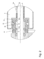
Figur 2- eine Ausschnittvergrößerung des Bereichs A von
Figur 1 .
- FIG. 1
- a deburring machine in a highly simplified vertical section;
- FIG. 2
- a detail enlargement of the area A of
FIG. 1 ,
In den Abbildungen sind nur die wesentlichen Teile der Entgratmaschine zu sehen, soweit sie für das Verständnis der Erfindung notwendig sind.In the figures, only the essential parts of the deburring machine are to be seen, as far as they are necessary for the understanding of the invention.
In einem Maschinenständer 1 ist eine Schleifwalze 2 um ihre horizontale Achse drehbar gelagert. Die Schleifwalze 2 sitzt koaxial auf einer Antriebswelle 3, welche durch zwei Wälzlager 4a, 4b im Maschinenständer 1 drehbar gelagert ist. Die beiden Wälzlager 4a, 4b sind mit einigem Abstand voneinander angeordnet. Ein drittes, hier nicht dargestelltes Wälzlager befindet sich am freien (in
Auf der zylindrischen Außenseite der Schleifwalze 2 ist ein Schleifbelag 5 zur abrasiven Bearbeitung eines flächigen Werkstücks 6 angeordnet. Der Schleifbelag 5 ist hier als endloser zylindrischer Schlauch ausgeführt und kann vom freien Ende der Antriebswelle 3 her in axialer Richtung auf die Schleifwalze 2 aufgezogen und in Gegenrichtung abgezogen werden. Zur Entfernung von Graten auf der im Wesentlichen ebenen Oberseite des Werkstücks 6 wird dieses in horizontaler Richtung unter der sich drehenden Schleifwalze 2 vorbeibewegt.On the cylindrical outer side of the
Angetrieben wird die Schleifwalze 2 von einem Antriebsmotor 7, einem starken Elektromotor. Dessen Motorwelle 8 ist ebenfalls horizontal im Maschinenständer 1 gelagert. Über einen ersten primären Riemenantrieb 9 treibt der Antriebsmotor 7 die Antriebswelle der Schleifwalze 2 an. Der Riemenantrieb 9 umfasst eine untere Riemenscheibe 10, eine obere Riemenscheibe 11, die auf der Antriebswelle 3 der Schleifwalze 2 sitzt, sowie einen über die Riemenscheiben 10, 11 geführten Treibriemen 12.The grinding
Die Antriebswelle 3 ist mit der Schleifwalze 2 drehfest verbunden. Gleichzeitig ist die Schleifwalze 2 auf der Antriebswelle 3 in axialer Richtung verschieblich gelagert. Realisiert wird dies durch zwei axiale Führungsschlitze 13a, 13b an der zylindrischen Innenseite der Schleifwalze 2, welche als Hohlzylinder ausgebildet ist, und zwei korrespondierende Kurvenrollen 14a, 14b, die auf der Antriebswelle 3 sitzen und in die Führungsschlitze 13a, 13b eingreifen. Zwischen Antriebswelle 3 und Schleifwalze 2 ist ein Gleitlager 15 angeordnet, so dass die Schleifwalze 2 leicht auf der Antriebswelle 3 axial hin- und hergleiten kann, soweit dies die relative Bewegung der Kurvenrollen 14a, 14b in den Führungsschlitzen 13a, 13b zulässt. Die Kurvenrollen 14a, 14b haben die Funktion von Mitnehmern, welche die Rotationsbewegung der Antriebswelle 3 auf die Schleifwalze 2 übertragen.The
Der Antriebsmotor 7 lässt nicht nur die Schleifwalze 2 rotieren, sondern bewirkt auch eine oszillierende Hin- und Her-Bewegung der Schleifwalze 2 gegenüber der Antriebswelle 3. Hierzu ist ein zweiter sekundärer Riemenantrieb 16 vorgesehen. Dieser Riemenantrieb 16 umfasst eine obere Riemenscheibe 17 und eine untere Riemenscheibe 18, über welche ein Treibriemen 19 läuft. Eine Verbindungswelle 20 ist horizontal und damit parallel zur Antriebswelle 3 und zur Motorwelle 8 im Maschinenständer 1 drehbar gelagert. Die untere Riemenscheibe 18 sitzt auf dem einen (in
Die Schleifwalze 2 hat an ihrer dem freien Ende gegenüberliegenden (in
An der freien (in
Die Nutkurve 25 verläuft sinusförmig auf der Mantelfläche des Steuerzylinders 23. Über eine volle Umdrehung betrachtet, wandert die Nutkurve 25 zwischen dem rechten und dem linken Rand des Steuerzylinders 23 hin- und her, wie in
Pro Umdrehung des Steuerzylinders 23 durchfährt der Kurvenreiter 26 eine volle Periode der sinusförmigen Nutkurve 25. Die Anzahl der Hin- und HerBewegungen der Schleifwalze 2 hängt von der Rotationsgeschwindigkeit des Steuerzylinders 23 im Verhältnis zur Rotationsgeschwindigkeit der Schleifwalze 2 ab. Dabei läuft die Schleifwalze 2 erheblich schneller um als der Steuerzylinder 23. Beispielsweise beträgt die Geschwindigkeit der Schleifwalze 1.000 U/min, während die Oszillationsfrequenz 2/sec beträgt. Durch Wahl der Übersetzungsverhältnisse der beiden Riemenantriebe 9 und 16 und insbesondere das Verhältnis der Durchmesser der Riemenscheiben 17, 18 des sekundären Riemenantriebs 16 lässt sich die Oszillationsfrequenz sehr leicht einstellen.Per revolution of the
- 11
- Maschinenständermachine stand
- 22
- Schleifwalzegrinding roll
- 33
- Antriebswelledrive shaft
- 4a, 4b4a, 4b
- WälzlagerRolling
- 55
- Schleifbelagabrasive coating
- 66
- Werkstückworkpiece
- 77
- Antriebsmotordrive motor
- 88th
- Motorwellemotor shaft
- 99
- primärer Riemenantriebprimary belt drive
- 1010
- untere Riemenscheibe (von 9)lower pulley (from 9)
- 1111
- obere Riemenscheibe (von 9)upper pulley (from 9)
- 1212
- Treibriemen (von 9)Transmission belt (from 9)
- 13a, 13b13a, 13b
- Führungsschlitze (in 2)Guide slots (in 2)
- 14a, 14b14a, 14b
- Kurvenrollen (an 3)Cam rollers (to 3)
- 1515
- Gleitlagerbearings
- 1616
- sekundärer Riemenantriebsecondary belt drive
- 1717
- obere Riemenscheibe (von 16)upper pulley (from 16)
- 1818
- untere Riemenscheibe (von 16)lower pulley (from 16)
- 1919
- Treibriemen (von 16)Transmission belt (from 16)
- 2020
- Verbindungswelleconnecting shaft
- 2121
- Riemenscheibe (an 20)Pulley (to 20)
- 2222
- Ausnehmung (in 2)Recess (in 2)
- 2323
- Steuerzylindercontrol cylinder
- 24a, 24b24a, 24b
- Wälzlager (von 23)Rolling bearings (from 23)
- 2525
- Nutkurve (in 23)Groove curve (in 23)
- 2626
- Kurvenreiter (an 2)Curve riders (at 2)
Claims (12)
eine Schleifwalze (2) mit einem Schleifbelag (5) zur abrasiven Bearbeitung des Werkstücks (6),
eine koaxiale, mit der Schleifwalze (2) drehfest verbundene Antriebswelle (3),
einen Antriebsmotor (7) zum Antrieb der Schleifwalze (2),
dadurch gekennzeichnet, dass
die Schleifwalze (2) auf der Antriebswelle (3) axial verschieblich gelagert ist,
mit dem Antriebsmotor (7) ein Verschiebegetriebe gekoppelt ist, welches eine oszillierende Hin- und Her-Bewegung der Schleifwalze (2) auf der Antriebswelle (3) erzeugt.Device for grinding and deburring a flat workpiece, comprising
a grinding roller (2) with an abrasive coating (5) for abrasive machining of the workpiece (6),
a coaxial, with the grinding roller (2) rotatably connected drive shaft (3),
a drive motor (7) for driving the grinding roller (2),
characterized in that
the grinding roller (2) is mounted so as to be axially displaceable on the drive shaft (3),
to the drive motor (7) a shift gear is coupled, which generates an oscillating reciprocating movement of the grinding roller (2) on the drive shaft (3).
Priority Applications (4)
| Application Number | Priority Date | Filing Date | Title |
|---|---|---|---|
| PL15165026T PL3085491T3 (en) | 2015-04-24 | 2015-04-24 | Device for grinding and deburring of a planar workpiece |
| EP15165026.4A EP3085491B1 (en) | 2015-04-24 | 2015-04-24 | Device for grinding and deburring of a planar workpiece |
| US15/134,471 US9950403B2 (en) | 2015-04-24 | 2016-04-21 | Device for grinding and deburring a flat workpiece |
| CN201610253385.1A CN106064331B (en) | 2015-04-24 | 2016-04-22 | For the device of grinding and the deburring of the workpiece of face type |
Applications Claiming Priority (1)
| Application Number | Priority Date | Filing Date | Title |
|---|---|---|---|
| EP15165026.4A EP3085491B1 (en) | 2015-04-24 | 2015-04-24 | Device for grinding and deburring of a planar workpiece |
Publications (2)
| Publication Number | Publication Date |
|---|---|
| EP3085491A1 true EP3085491A1 (en) | 2016-10-26 |
| EP3085491B1 EP3085491B1 (en) | 2017-04-12 |
Family
ID=53002574
Family Applications (1)
| Application Number | Title | Priority Date | Filing Date |
|---|---|---|---|
| EP15165026.4A Active EP3085491B1 (en) | 2015-04-24 | 2015-04-24 | Device for grinding and deburring of a planar workpiece |
Country Status (4)
| Country | Link |
|---|---|
| US (1) | US9950403B2 (en) |
| EP (1) | EP3085491B1 (en) |
| CN (1) | CN106064331B (en) |
| PL (1) | PL3085491T3 (en) |
Cited By (4)
| Publication number | Priority date | Publication date | Assignee | Title |
|---|---|---|---|---|
| CN108655842A (en) * | 2018-05-28 | 2018-10-16 | 郑州荣献新材料技术有限公司 | A kind of architectural engineering clamping hoop type short steel pipes grinding device |
| CN112570560A (en) * | 2020-11-03 | 2021-03-30 | 鄢海锋 | Punch forming die capable of performing optimized treatment on surface of workpiece |
| CN113211307A (en) * | 2021-05-25 | 2021-08-06 | 安徽鑫艺达抛光机械股份有限公司 | Swing grinding head of flat polishing machine |
| EP4015147A1 (en) | 2020-12-16 | 2022-06-22 | ARKU Maschinenbau GmbH | Machine for working sheet metal parts |
Families Citing this family (7)
| Publication number | Priority date | Publication date | Assignee | Title |
|---|---|---|---|---|
| CN206200893U (en) * | 2016-10-20 | 2017-05-31 | 布兰特·戈登·麦克阿瑟 | A kind of electronic chisel for coordinating Household electric drill to use |
| US10632549B2 (en) * | 2016-12-15 | 2020-04-28 | Ford Motor Company | Blanking and trim die including an integrated power grinding tool |
| CN107042181A (en) * | 2017-06-21 | 2017-08-15 | 孙美娟 | A kind of bridge equipment |
| CN107234532A (en) * | 2017-06-21 | 2017-10-10 | 孙美娟 | A kind of multi-functional bridge equipment |
| TWM561594U (en) * | 2017-12-21 | 2018-06-11 | Zhuang Bo Chang | Grinding machine with traverse grinding |
| CN111102078B (en) * | 2019-11-28 | 2022-10-18 | 四川泛华航空仪表电器有限公司 | Method for removing oxide layer of contact rod of ignition electric nozzle |
| CN112571077A (en) * | 2020-12-22 | 2021-03-30 | 南京皓政科技有限公司 | Rust removal device suitable for steel pipes with different diameters |
Citations (7)
| Publication number | Priority date | Publication date | Assignee | Title |
|---|---|---|---|---|
| US3435566A (en) * | 1964-07-20 | 1969-04-01 | Koninkl Nl Vliegtuigenfabriek | Method of deburring a flat workpiece |
| US3661018A (en) * | 1970-06-05 | 1972-05-09 | Richard K Keefer | Electric brusher |
| US4397055A (en) * | 1980-10-20 | 1983-08-09 | Cuchiara Samuel M | Reversable shaft with rotary and selective oscillating motion |
| US4537264A (en) * | 1974-10-16 | 1985-08-27 | Robert Bosch Gmbh | Power-driven hand tool |
| DE29618516U1 (en) * | 1995-10-23 | 1997-02-20 | Waxing Corp Of America Inc | Power tool |
| US20090007802A1 (en) * | 2007-07-02 | 2009-01-08 | Isaac Taitler | Method and device for multi-purpose applications using interchangeable heads |
| DE102007048544A1 (en) | 2007-10-09 | 2009-04-16 | Paul Ernst Maschinenfabrik Gmbh | Device for grinding workpieces |
Family Cites Families (12)
| Publication number | Priority date | Publication date | Assignee | Title |
|---|---|---|---|---|
| US101167A (en) * | 1870-03-22 | Improved machine for burnishing boot and shoe heels | ||
| US1849868A (en) * | 1923-11-08 | 1932-03-15 | Cincinnati Milling Machine Co | Grinder wheel oscillator |
| US3943666A (en) * | 1974-07-31 | 1976-03-16 | Dysan Corporation | Method and apparatus for burnishing flexible recording material |
| NL7904403A (en) * | 1979-06-05 | 1980-12-09 | Linden Bv Machine | APPARATUS FOR SURFACE PROCESSING OF OBJECTS. |
| US5402604A (en) * | 1993-03-17 | 1995-04-04 | Ryobi Motor Products | Oscillating spindle sander |
| DE4409300A1 (en) * | 1994-03-18 | 1995-09-21 | Schloemann Siemag Ag | Device for processing rolls during the rolling process |
| US6860797B1 (en) * | 2003-10-31 | 2005-03-01 | Bor Yann Chuang | Reciprocating device for a polishing roller of an emery-polishing machine |
| CN201329532Y (en) * | 2008-12-29 | 2009-10-21 | 浙江名媛工艺饰品有限公司 | Reciprocating movement structure for grinding and polishing roll |
| US20110028074A1 (en) * | 2009-08-03 | 2011-02-03 | Canon Kabushiki Kaisha | Polishing method for a workpiece and polishing tool used for the polishing method |
| CN201881240U (en) * | 2010-10-28 | 2011-06-29 | 浙江名媛工艺饰品有限公司 | Crystal grinding and polishing machine |
| CN203185100U (en) * | 2013-04-26 | 2013-09-11 | 付建芳 | Edge brushing device of electrode board edge brushing machine |
| CN204108766U (en) * | 2014-08-15 | 2015-01-21 | 福建时创电子科技有限公司 | A kind of small circuit board surface-treated Plate grinder |
-
2015
- 2015-04-24 EP EP15165026.4A patent/EP3085491B1/en active Active
- 2015-04-24 PL PL15165026T patent/PL3085491T3/en unknown
-
2016
- 2016-04-21 US US15/134,471 patent/US9950403B2/en active Active
- 2016-04-22 CN CN201610253385.1A patent/CN106064331B/en active Active
Patent Citations (8)
| Publication number | Priority date | Publication date | Assignee | Title |
|---|---|---|---|---|
| US3435566A (en) * | 1964-07-20 | 1969-04-01 | Koninkl Nl Vliegtuigenfabriek | Method of deburring a flat workpiece |
| DE1502538A1 (en) | 1964-07-20 | 1969-04-10 | Konink Nl Vliegguigenfabriek F | Method and device for trimming a flat workpiece |
| US3661018A (en) * | 1970-06-05 | 1972-05-09 | Richard K Keefer | Electric brusher |
| US4537264A (en) * | 1974-10-16 | 1985-08-27 | Robert Bosch Gmbh | Power-driven hand tool |
| US4397055A (en) * | 1980-10-20 | 1983-08-09 | Cuchiara Samuel M | Reversable shaft with rotary and selective oscillating motion |
| DE29618516U1 (en) * | 1995-10-23 | 1997-02-20 | Waxing Corp Of America Inc | Power tool |
| US20090007802A1 (en) * | 2007-07-02 | 2009-01-08 | Isaac Taitler | Method and device for multi-purpose applications using interchangeable heads |
| DE102007048544A1 (en) | 2007-10-09 | 2009-04-16 | Paul Ernst Maschinenfabrik Gmbh | Device for grinding workpieces |
Cited By (4)
| Publication number | Priority date | Publication date | Assignee | Title |
|---|---|---|---|---|
| CN108655842A (en) * | 2018-05-28 | 2018-10-16 | 郑州荣献新材料技术有限公司 | A kind of architectural engineering clamping hoop type short steel pipes grinding device |
| CN112570560A (en) * | 2020-11-03 | 2021-03-30 | 鄢海锋 | Punch forming die capable of performing optimized treatment on surface of workpiece |
| EP4015147A1 (en) | 2020-12-16 | 2022-06-22 | ARKU Maschinenbau GmbH | Machine for working sheet metal parts |
| CN113211307A (en) * | 2021-05-25 | 2021-08-06 | 安徽鑫艺达抛光机械股份有限公司 | Swing grinding head of flat polishing machine |
Also Published As
| Publication number | Publication date |
|---|---|
| PL3085491T3 (en) | 2017-09-29 |
| CN106064331B (en) | 2018-05-18 |
| US9950403B2 (en) | 2018-04-24 |
| EP3085491B1 (en) | 2017-04-12 |
| CN106064331A (en) | 2016-11-02 |
| US20160332275A1 (en) | 2016-11-17 |
Similar Documents
| Publication | Publication Date | Title |
|---|---|---|
| EP3085491B1 (en) | Device for grinding and deburring of a planar workpiece | |
| DE1652513B2 (en) | Machine for sawing fragile, especially crystalline materials | |
| DE3416664C2 (en) | Device for controlling the cutting speed of the saw blade of a band saw machine | |
| DE3000321C2 (en) | Rotating punching device | |
| DE2653173A1 (en) | METHOD AND DEVICE FOR CONTROLLING THE TENSION OF A CONTINUOUSLY CYCLE WORKING MACHINE | |
| DE2714222C2 (en) | Process and machine for grinding the thrust collars of the inner rings of tapered roller bearings | |
| DE69922998T2 (en) | DEVICE FOR POSITIONING A TOOL OR A TOOL HOLDER IN A MACHINE FOR MACHINING A RAIL MATERIAL | |
| DE2331466C3 (en) | Machine for the production of headless threaded parts | |
| DE2834149C2 (en) | Dressing device for a device working with a cup grinding wheel for grinding spiral-toothed bevel gears | |
| DE3533082A1 (en) | Process and apparatus for the fine machining of rotationally symmetrical workpieces | |
| DE4138896A1 (en) | Spring coiling machine - has alternative crank and cam mechanisms to give rotary or straight cut | |
| DE465862C (en) | Grinding of the flat faces of rotating bodies, in particular cylindrical rollers, round disks and rings | |
| DE2065101A1 (en) | Lap forming device | |
| DE1560126C3 (en) | Device for screw cutting a tubular fabric, in particular consisting of knitted fabric | |
| EP3159068A1 (en) | Forming machine for pressing/pressure rolling and method for pressing/pressure rolling | |
| DE2819778A1 (en) | FLYING SCISSORS | |
| DE1178677B (en) | Process for toothing a spiral bevel gear or spiral hyperboloid gear, the tooth flanks of which are helical surfaces with changing pitch, and a machine with a face cutter head to carry out this process | |
| DE102004043583B4 (en) | Expanded grid machine and method for producing a stretched grid | |
| DE664108C (en) | Device for dressing profiled grinding wheels | |
| EP1724042A2 (en) | Groove slotting method and groove slotting machine | |
| DE643632C (en) | Machine for copy grinding, especially the cams of control shafts | |
| DE3019003C2 (en) | ||
| DE3033148A1 (en) | MACHINE FOR CUTTING TEXTILE MATERIAL ROLLS | |
| DE1527653A1 (en) | System for the continuous cleaning of the outer surface of round rolling stock from scale and rust | |
| DE624663C (en) | Speed change gearbox for the drive of continuously working blueprint machines |
Legal Events
| Date | Code | Title | Description |
|---|---|---|---|
| PUAI | Public reference made under article 153(3) epc to a published international application that has entered the european phase |
Free format text: ORIGINAL CODE: 0009012 |
|
| 17P | Request for examination filed |
Effective date: 20160226 |
|
| AK | Designated contracting states |
Kind code of ref document: A1 Designated state(s): AL AT BE BG CH CY CZ DE DK EE ES FI FR GB GR HR HU IE IS IT LI LT LU LV MC MK MT NL NO PL PT RO RS SE SI SK SM TR |
|
| AX | Request for extension of the european patent |
Extension state: BA ME |
|
| GRAP | Despatch of communication of intention to grant a patent |
Free format text: ORIGINAL CODE: EPIDOSNIGR1 |
|
| RAP1 | Party data changed (applicant data changed or rights of an application transferred) |
Owner name: ARKU MASCHINENBAU GMBH |
|
| INTG | Intention to grant announced |
Effective date: 20161121 |
|
| GRAS | Grant fee paid |
Free format text: ORIGINAL CODE: EPIDOSNIGR3 |
|
| GRAA | (expected) grant |
Free format text: ORIGINAL CODE: 0009210 |
|
| AK | Designated contracting states |
Kind code of ref document: B1 Designated state(s): AL AT BE BG CH CY CZ DE DK EE ES FI FR GB GR HR HU IE IS IT LI LT LU LV MC MK MT NL NO PL PT RO RS SE SI SK SM TR |
|
| REG | Reference to a national code |
Ref country code: GB Ref legal event code: FG4D Free format text: NOT ENGLISH |
|
| REG | Reference to a national code |
Ref country code: CH Ref legal event code: EP |
|
| REG | Reference to a national code |
Ref country code: IE Ref legal event code: FG4D Free format text: LANGUAGE OF EP DOCUMENT: GERMAN |
|
| REG | Reference to a national code |
Ref country code: AT Ref legal event code: REF Ref document number: 883377 Country of ref document: AT Kind code of ref document: T Effective date: 20170515 |
|
| REG | Reference to a national code |
Ref country code: DE Ref legal event code: R096 Ref document number: 502015000843 Country of ref document: DE |
|
| REG | Reference to a national code |
Ref country code: NL Ref legal event code: FP |
|
| REG | Reference to a national code |
Ref country code: LT Ref legal event code: MG4D |
|
| PG25 | Lapsed in a contracting state [announced via postgrant information from national office to epo] |
Ref country code: HR Free format text: LAPSE BECAUSE OF FAILURE TO SUBMIT A TRANSLATION OF THE DESCRIPTION OR TO PAY THE FEE WITHIN THE PRESCRIBED TIME-LIMIT Effective date: 20170412 Ref country code: FI Free format text: LAPSE BECAUSE OF FAILURE TO SUBMIT A TRANSLATION OF THE DESCRIPTION OR TO PAY THE FEE WITHIN THE PRESCRIBED TIME-LIMIT Effective date: 20170412 Ref country code: ES Free format text: LAPSE BECAUSE OF FAILURE TO SUBMIT A TRANSLATION OF THE DESCRIPTION OR TO PAY THE FEE WITHIN THE PRESCRIBED TIME-LIMIT Effective date: 20170412 Ref country code: LT Free format text: LAPSE BECAUSE OF FAILURE TO SUBMIT A TRANSLATION OF THE DESCRIPTION OR TO PAY THE FEE WITHIN THE PRESCRIBED TIME-LIMIT Effective date: 20170412 Ref country code: GR Free format text: LAPSE BECAUSE OF FAILURE TO SUBMIT A TRANSLATION OF THE DESCRIPTION OR TO PAY THE FEE WITHIN THE PRESCRIBED TIME-LIMIT Effective date: 20170713 Ref country code: NO Free format text: LAPSE BECAUSE OF FAILURE TO SUBMIT A TRANSLATION OF THE DESCRIPTION OR TO PAY THE FEE WITHIN THE PRESCRIBED TIME-LIMIT Effective date: 20170712 |
|
| PG25 | Lapsed in a contracting state [announced via postgrant information from national office to epo] |
Ref country code: BG Free format text: LAPSE BECAUSE OF FAILURE TO SUBMIT A TRANSLATION OF THE DESCRIPTION OR TO PAY THE FEE WITHIN THE PRESCRIBED TIME-LIMIT Effective date: 20170712 Ref country code: SE Free format text: LAPSE BECAUSE OF FAILURE TO SUBMIT A TRANSLATION OF THE DESCRIPTION OR TO PAY THE FEE WITHIN THE PRESCRIBED TIME-LIMIT Effective date: 20170412 Ref country code: IS Free format text: LAPSE BECAUSE OF FAILURE TO SUBMIT A TRANSLATION OF THE DESCRIPTION OR TO PAY THE FEE WITHIN THE PRESCRIBED TIME-LIMIT Effective date: 20170812 Ref country code: RS Free format text: LAPSE BECAUSE OF FAILURE TO SUBMIT A TRANSLATION OF THE DESCRIPTION OR TO PAY THE FEE WITHIN THE PRESCRIBED TIME-LIMIT Effective date: 20170412 Ref country code: LV Free format text: LAPSE BECAUSE OF FAILURE TO SUBMIT A TRANSLATION OF THE DESCRIPTION OR TO PAY THE FEE WITHIN THE PRESCRIBED TIME-LIMIT Effective date: 20170412 |
|
| REG | Reference to a national code |
Ref country code: DE Ref legal event code: R097 Ref document number: 502015000843 Country of ref document: DE |
|
| REG | Reference to a national code |
Ref country code: IE Ref legal event code: MM4A |
|
| PG25 | Lapsed in a contracting state [announced via postgrant information from national office to epo] |
Ref country code: DK Free format text: LAPSE BECAUSE OF FAILURE TO SUBMIT A TRANSLATION OF THE DESCRIPTION OR TO PAY THE FEE WITHIN THE PRESCRIBED TIME-LIMIT Effective date: 20170412 Ref country code: MC Free format text: LAPSE BECAUSE OF FAILURE TO SUBMIT A TRANSLATION OF THE DESCRIPTION OR TO PAY THE FEE WITHIN THE PRESCRIBED TIME-LIMIT Effective date: 20170412 Ref country code: SK Free format text: LAPSE BECAUSE OF FAILURE TO SUBMIT A TRANSLATION OF THE DESCRIPTION OR TO PAY THE FEE WITHIN THE PRESCRIBED TIME-LIMIT Effective date: 20170412 Ref country code: EE Free format text: LAPSE BECAUSE OF FAILURE TO SUBMIT A TRANSLATION OF THE DESCRIPTION OR TO PAY THE FEE WITHIN THE PRESCRIBED TIME-LIMIT Effective date: 20170412 |
|
| PLBE | No opposition filed within time limit |
Free format text: ORIGINAL CODE: 0009261 |
|
| STAA | Information on the status of an ep patent application or granted ep patent |
Free format text: STATUS: NO OPPOSITION FILED WITHIN TIME LIMIT |
|
| PG25 | Lapsed in a contracting state [announced via postgrant information from national office to epo] |
Ref country code: LU Free format text: LAPSE BECAUSE OF NON-PAYMENT OF DUE FEES Effective date: 20170424 Ref country code: SM Free format text: LAPSE BECAUSE OF FAILURE TO SUBMIT A TRANSLATION OF THE DESCRIPTION OR TO PAY THE FEE WITHIN THE PRESCRIBED TIME-LIMIT Effective date: 20170412 |
|
| REG | Reference to a national code |
Ref country code: FR Ref legal event code: ST Effective date: 20180212 |
|
| 26N | No opposition filed |
Effective date: 20180115 |
|
| REG | Reference to a national code |
Ref country code: BE Ref legal event code: MM Effective date: 20170430 |
|
| PG25 | Lapsed in a contracting state [announced via postgrant information from national office to epo] |
Ref country code: IE Free format text: LAPSE BECAUSE OF NON-PAYMENT OF DUE FEES Effective date: 20170424 |
|
| PG25 | Lapsed in a contracting state [announced via postgrant information from national office to epo] |
Ref country code: BE Free format text: LAPSE BECAUSE OF NON-PAYMENT OF DUE FEES Effective date: 20170430 Ref country code: FR Free format text: LAPSE BECAUSE OF NON-PAYMENT OF DUE FEES Effective date: 20170612 |
|
| PG25 | Lapsed in a contracting state [announced via postgrant information from national office to epo] |
Ref country code: MT Free format text: LAPSE BECAUSE OF FAILURE TO SUBMIT A TRANSLATION OF THE DESCRIPTION OR TO PAY THE FEE WITHIN THE PRESCRIBED TIME-LIMIT Effective date: 20170412 |
|
| PG25 | Lapsed in a contracting state [announced via postgrant information from national office to epo] |
Ref country code: HU Free format text: LAPSE BECAUSE OF FAILURE TO SUBMIT A TRANSLATION OF THE DESCRIPTION OR TO PAY THE FEE WITHIN THE PRESCRIBED TIME-LIMIT; INVALID AB INITIO Effective date: 20150424 |
|
| PG25 | Lapsed in a contracting state [announced via postgrant information from national office to epo] |
Ref country code: RO Free format text: LAPSE BECAUSE OF FAILURE TO SUBMIT A TRANSLATION OF THE DESCRIPTION OR TO PAY THE FEE WITHIN THE PRESCRIBED TIME-LIMIT Effective date: 20170412 |
|
| PG25 | Lapsed in a contracting state [announced via postgrant information from national office to epo] |
Ref country code: SI Free format text: LAPSE BECAUSE OF FAILURE TO SUBMIT A TRANSLATION OF THE DESCRIPTION OR TO PAY THE FEE WITHIN THE PRESCRIBED TIME-LIMIT Effective date: 20170412 |
|
| PG25 | Lapsed in a contracting state [announced via postgrant information from national office to epo] |
Ref country code: CY Free format text: LAPSE BECAUSE OF FAILURE TO SUBMIT A TRANSLATION OF THE DESCRIPTION OR TO PAY THE FEE WITHIN THE PRESCRIBED TIME-LIMIT Effective date: 20170412 |
|
| PG25 | Lapsed in a contracting state [announced via postgrant information from national office to epo] |
Ref country code: MK Free format text: LAPSE BECAUSE OF FAILURE TO SUBMIT A TRANSLATION OF THE DESCRIPTION OR TO PAY THE FEE WITHIN THE PRESCRIBED TIME-LIMIT Effective date: 20170412 |
|
| GBPC | Gb: european patent ceased through non-payment of renewal fee |
Effective date: 20190424 |
|
| PG25 | Lapsed in a contracting state [announced via postgrant information from national office to epo] |
Ref country code: GB Free format text: LAPSE BECAUSE OF NON-PAYMENT OF DUE FEES Effective date: 20190424 |
|
| PG25 | Lapsed in a contracting state [announced via postgrant information from national office to epo] |
Ref country code: TR Free format text: LAPSE BECAUSE OF FAILURE TO SUBMIT A TRANSLATION OF THE DESCRIPTION OR TO PAY THE FEE WITHIN THE PRESCRIBED TIME-LIMIT Effective date: 20170412 |
|
| PG25 | Lapsed in a contracting state [announced via postgrant information from national office to epo] |
Ref country code: PT Free format text: LAPSE BECAUSE OF FAILURE TO SUBMIT A TRANSLATION OF THE DESCRIPTION OR TO PAY THE FEE WITHIN THE PRESCRIBED TIME-LIMIT Effective date: 20170412 |
|
| PG25 | Lapsed in a contracting state [announced via postgrant information from national office to epo] |
Ref country code: AL Free format text: LAPSE BECAUSE OF FAILURE TO SUBMIT A TRANSLATION OF THE DESCRIPTION OR TO PAY THE FEE WITHIN THE PRESCRIBED TIME-LIMIT Effective date: 20170412 |
|
| P01 | Opt-out of the competence of the unified patent court (upc) registered |
Effective date: 20230524 |
|
| PGFP | Annual fee paid to national office [announced via postgrant information from national office to epo] |
Ref country code: NL Payment date: 20230417 Year of fee payment: 9 |
|
| PGFP | Annual fee paid to national office [announced via postgrant information from national office to epo] |
Ref country code: IT Payment date: 20230428 Year of fee payment: 9 Ref country code: DE Payment date: 20230418 Year of fee payment: 9 Ref country code: CZ Payment date: 20230417 Year of fee payment: 9 Ref country code: CH Payment date: 20230502 Year of fee payment: 9 |
|
| PGFP | Annual fee paid to national office [announced via postgrant information from national office to epo] |
Ref country code: PL Payment date: 20230413 Year of fee payment: 9 Ref country code: AT Payment date: 20230414 Year of fee payment: 9 |