EP3073761A1 - Loudspeaker - Google Patents
Loudspeaker Download PDFInfo
- Publication number
- EP3073761A1 EP3073761A1 EP16161140.5A EP16161140A EP3073761A1 EP 3073761 A1 EP3073761 A1 EP 3073761A1 EP 16161140 A EP16161140 A EP 16161140A EP 3073761 A1 EP3073761 A1 EP 3073761A1
- Authority
- EP
- European Patent Office
- Prior art keywords
- loudspeaker
- front wall
- sound
- housing
- wall
- Prior art date
- Legal status (The legal status is an assumption and is not a legal conclusion. Google has not performed a legal analysis and makes no representation as to the accuracy of the status listed.)
- Withdrawn
Links
- 239000000463 material Substances 0.000 claims description 52
- 230000002787 reinforcement Effects 0.000 claims description 16
- 229910052500 inorganic mineral Inorganic materials 0.000 claims description 14
- 239000011707 mineral Substances 0.000 claims description 14
- 239000007787 solid Substances 0.000 claims description 11
- 230000007423 decrease Effects 0.000 claims description 3
- 239000012528 membrane Substances 0.000 description 27
- 238000000926 separation method Methods 0.000 description 9
- 238000004026 adhesive bonding Methods 0.000 description 4
- 239000002131 composite material Substances 0.000 description 3
- 238000005192 partition Methods 0.000 description 3
- XAGFODPZIPBFFR-UHFFFAOYSA-N aluminium Chemical compound [Al] XAGFODPZIPBFFR-UHFFFAOYSA-N 0.000 description 2
- 229910052782 aluminium Inorganic materials 0.000 description 2
- 230000005540 biological transmission Effects 0.000 description 2
- 238000013461 design Methods 0.000 description 2
- 230000000694 effects Effects 0.000 description 2
- 238000005516 engineering process Methods 0.000 description 2
- 230000002349 favourable effect Effects 0.000 description 2
- 239000012530 fluid Substances 0.000 description 2
- 239000007789 gas Substances 0.000 description 2
- 239000004579 marble Substances 0.000 description 2
- 229920003229 poly(methyl methacrylate) Polymers 0.000 description 2
- 239000004926 polymethyl methacrylate Substances 0.000 description 2
- 238000012552 review Methods 0.000 description 2
- NIXOWILDQLNWCW-UHFFFAOYSA-N acrylic acid group Chemical group C(C=C)(=O)O NIXOWILDQLNWCW-UHFFFAOYSA-N 0.000 description 1
- WNROFYMDJYEPJX-UHFFFAOYSA-K aluminium hydroxide Chemical compound [OH-].[OH-].[OH-].[Al+3] WNROFYMDJYEPJX-UHFFFAOYSA-K 0.000 description 1
- 230000003321 amplification Effects 0.000 description 1
- 239000003054 catalyst Substances 0.000 description 1
- 239000003795 chemical substances by application Substances 0.000 description 1
- 238000010276 construction Methods 0.000 description 1
- 238000013016 damping Methods 0.000 description 1
- 238000002955 isolation Methods 0.000 description 1
- 230000000670 limiting effect Effects 0.000 description 1
- 238000000034 method Methods 0.000 description 1
- 238000012986 modification Methods 0.000 description 1
- 230000004048 modification Effects 0.000 description 1
- 238000003199 nucleic acid amplification method Methods 0.000 description 1
- 230000010355 oscillation Effects 0.000 description 1
- 230000035939 shock Effects 0.000 description 1
- 239000004575 stone Substances 0.000 description 1
Images


Classifications
-
- H—ELECTRICITY
- H04—ELECTRIC COMMUNICATION TECHNIQUE
- H04R—LOUDSPEAKERS, MICROPHONES, GRAMOPHONE PICK-UPS OR LIKE ACOUSTIC ELECTROMECHANICAL TRANSDUCERS; DEAF-AID SETS; PUBLIC ADDRESS SYSTEMS
- H04R1/00—Details of transducers, loudspeakers or microphones
- H04R1/20—Arrangements for obtaining desired frequency or directional characteristics
- H04R1/22—Arrangements for obtaining desired frequency or directional characteristics for obtaining desired frequency characteristic only
- H04R1/28—Transducer mountings or enclosures modified by provision of mechanical or acoustic impedances, e.g. resonator, damping means
- H04R1/2807—Enclosures comprising vibrating or resonating arrangements
- H04R1/283—Enclosures comprising vibrating or resonating arrangements using a passive diaphragm
- H04R1/2834—Enclosures comprising vibrating or resonating arrangements using a passive diaphragm for loudspeaker transducers
-
- H—ELECTRICITY
- H04—ELECTRIC COMMUNICATION TECHNIQUE
- H04R—LOUDSPEAKERS, MICROPHONES, GRAMOPHONE PICK-UPS OR LIKE ACOUSTIC ELECTROMECHANICAL TRANSDUCERS; DEAF-AID SETS; PUBLIC ADDRESS SYSTEMS
- H04R2201/00—Details of transducers, loudspeakers or microphones covered by H04R1/00 but not provided for in any of its subgroups
- H04R2201/02—Details casings, cabinets or mounting therein for transducers covered by H04R1/02 but not provided for in any of its subgroups
- H04R2201/021—Transducers or their casings adapted for mounting in or to a wall or ceiling
-
- H—ELECTRICITY
- H04—ELECTRIC COMMUNICATION TECHNIQUE
- H04R—LOUDSPEAKERS, MICROPHONES, GRAMOPHONE PICK-UPS OR LIKE ACOUSTIC ELECTROMECHANICAL TRANSDUCERS; DEAF-AID SETS; PUBLIC ADDRESS SYSTEMS
- H04R2440/00—Bending wave transducers covered by H04R, not provided for in its groups
Definitions
- the present invention relates to a loudspeaker having a housing and a first sound generator. Moreover, the present invention relates to a vibration diaphragm for a loudspeaker.
- Loudspeakers themselves are known in the art. The structure and underlying technology should therefore not be discussed in detail here. Loudspeakers contain so-called sound generators, which are usually equipped with a vibration membrane in order to deliver the sound waves generated by the sound generator to the surrounding medium (air). Such sound generators exist for the low, mid, and high frequency ranges, with the frequency range of music perceptibility ranging from about 40 Hz to about 8,000 kHz.
- a loudspeaker sound generators can each be accommodated with a vibration diaphragm in a suitable loudspeaker box.
- a subwoofer basic box
- a list of such subwoofer in any place in the room is possible.
- the largest possible amount of air has to be moved, for which subwoofers either use a sound generator with the largest possible membrane area or else one Insert sound generator whose membrane surface can be deflected with large amplitude.
- the signal is supplied to a subwoofer via a loudspeaker switch, which filters the low-frequency components from the signals for the sound generators and then forwards them to the sound generator of the subwoofer, while the other components are forwarded to the remaining sound generators.
- exciters are known that represent membraneless sound generators. They use a solid object as a "membrane", for which purpose an exciter is fixed to such an object that it vibrates. Such exciters are mainly used in the field of sound furniture. For example, they can be stuck under tables, in cabinets, in ceilings, etc., thus acting as an invisible loudspeaker.
- Subwoofers are often large, unwieldy devices that require a lot of space. Separated from the subwoofers, high and midrange speakers must be placed in the room. This usually involves long cable runs. Wireless systems have not worked without sacrificing transmission and / or listening quality.
- the sound quality of furniture with directly attached exciters depends strongly on the surface, the geometry as well as the structure and the material of the respective furniture. In particular, bonding, gluing, joints, etc. disturb the sound propagation and have a strong effect on the sound quality.
- the DE 44 46 690 A1 to reduce the previously necessary subwoofer housing volume before a speaker assembly before, in the two Speakers are connected in series in a common housing.
- a speaker for the entire frequency range In the front wall of the housing is a speaker for the entire frequency range, while in a partition wall of the housing, a speaker for low frequencies is arranged.
- the rear wall of the housing In the rear wall of the housing, for example, there is a sound opening.
- the loudspeaker for low frequency range reproduction in the middle and high frequency ranges acts as a passive radiator of the loudspeaker for the entire frequency range reproduction.
- the reproduced sound pressure level in the low frequency range is increased and smoothed by the proposed arrangement there.
- the sound opening in the back of the housing can be replaced by another passive radiator, which can represent a resiliently inserted into the rear wall of the housing wall or a vibration membrane used there. This leads to a further improvement of the characteristic in the low frequency range.
- a loudspeaker is formed by a loudspeaker housing, which is divided by an intermediate wall into two cavities.
- the intermediate wall has a driver connected in series with a passive radiator in the front of the housing so that the sound producing side of the driver and the passive radiator face in the same direction.
- the passive radiator is designed as a flat rectangular passive radiator, ie as a flat rectangular membrane, which is inserted into the front wall of the housing.
- Passive radiators thus form in a housing wall or in an intermediate wall within the housing of a loudspeaker vibrationally decoupled sound generator or vibration diaphragm, which are set in vibration by a sound generator acting as a driver.
- Such passive radiators have in the presently considered particular use of a speaker as a sound furniture the disadvantage that a mounted in a visible front wall of the speaker housing passive radiator reduces the stability of the housing front wall.
- the part of the front wall that forms the passive radiator is mechanically less resilient and sensitive to pressure, shock or the like. In addition, this is in certain uses of sound furniture aesthetic disadvantages.
- An inventive loudspeaker has a housing and (at least) a first sound generator, wherein the first sound generator is mounted in a mounting wall and limits this mounting wall with a front side wall of the housing spaced apart on a sound-generating side of the first sound generator and an airtight space.
- the front wall forms a vibration diaphragm of the loudspeaker, which is rigidly connected to the housing of the loudspeaker.
- the first sound generator may also be referred to as an airborne sound transducer.
- the mounting wall and the front wall of the speaker may be substantially parallel to each other. Both walls define an airtight space, which is bounded on the other sides in particular by the housing of the speaker.
- the (first) sound generator is held by the mounting wall and, in particular via its own vibration membrane from sound waves in the hermetically sealed space. The sound waves propagate to the front wall of the housing and vibrate them in turn, so that the front wall (or at least part of this front wall) the vibration membrane of the speaker.
- the sound-transmitting surface can be increased by a factor corresponding to the ratio of the area of the vibration diaphragm of the loudspeaker formed by the front wall to the surface of the vibration diaphragm of the sound generator.
- the effective area of the vibrating diaphragm of the loudspeaker can be increased many times as compared with the actual area of the sound generator vibrating diaphragm, whereby a much better sound quality can be achieved especially in the low frequency range than with known solutions of the prior art.
- the vibration membrane of the speaker forming part of the front wall of the housing with the housing is rigid or rigid.
- this is not a vibration-decoupled attachment. Rather, forms the part of the front wall functioning as a vibration diaphragm of the speaker together with the front wall a solid surface, it being particularly advantageous if the entire front wall of the housing of the speaker forms the vibration membrane.
- the acting as a vibration member part of the front wall is frictionally, material and / or positively connected to the rest of the housing or may also be made in one piece. A cohesive connection, in particular by gluing, has proved to be particularly advantageous.
- the front wall of the housing a one-piece solid surface that is rigidly and rigidly connected to the rest of the housing.
- the entire front wall can serve as a vibration diaphragm of the speaker.
- the housing then forms a stable composite together with the front wall, so that the loudspeaker according to the invention can be used in a particularly suitable manner as sound furniture.
- the entire front wall of the vibration membrane of Speaker forms.
- the front side of the loudspeaker according to the invention used as sound furniture thus transmits the sound into the room.
- the sound quality is many times higher, because not an exciter directly sets the front of the housing in vibration, but a relatively small speaker (sound generator with vibration membrane in the mounting wall) the sound waves over the hermetically sealed space transfers to the large area of the front wall.
- this front wall simultaneously forms the vibration diaphragm of the loudspeaker and part of the furniture, such as a panel, an image, a wall unit, a sliding door or the like.
- said factor ie the ratio of the area of the vibration membrane formed by the front wall (or at least a part thereof) to the surface of the actual sound generator vibration membrane, is at least 2.0, more particularly 4.0 or 5.0 or 10 or 20 to about 25 or 30. In particular, ratios of 4 to 10 are preferred. Due to the fact that both oscillating surfaces are coupled via the airtight space, it is possible according to the invention to achieve a high magnification of the surface which effectively transmits sound to the surroundings.
- the front wall is, as will be explained below (at least in part) made of a suitable material capable of vibrating. It is advantageous if the entire front wall or at least the largest part of the front wall forms the vibration diaphragm of the loudspeaker according to the invention.
- the first sound generator mounted in the mounting wall is, in particular, an airborne sound transducer (woofer) for generating sound frequencies in a first frequency range, in particular in the range from 25 Hz to 600 Hz.
- an airborne sound transducer woofer
- the first sound generator mounted in the mounting wall emits sound waves only to the airtight space without vibrating the mounting wall itself (vibration-decoupled connection).
- the sound generator can be accommodated swinging in the mounting wall and indeed in such a way that as little vibration as possible is transmitted to the mounting wall itself.
- the holder made of a first material
- the holder can be integrated into a mounting wall (made of a second rigid material).
- a one-piece design is also possible, wherein the mounting wall has a comparatively high material thickness, in particular in comparison to the front wall, so that it is hardly vibrated.
- the vibration membrane forming part of the front wall of the speaker is made of a mineral material.
- mineral materials are mineral-organic composites, as they are for example under the name Corian on the market.
- Corian consists of about 66 wt .-% of a modification of aluminum hydroxide and about 33 wt .-% of polymethyl methacrylate (PMMA) and of catalysts and other curing agents.
- PMMA polymethyl methacrylate
- a mineral material used herein may contain about 40% ( ⁇ 10%) ground stone or marble and about 60% ( ⁇ 10%) acrylic. Externally, the material resembles marble, but is lighter, can be cut and cut, but also thermally deformed three-dimensionally.
- the housing of the speaker has a rear wall which lies on the side facing away from the front wall of the mounting wall and spaced from this mounting wall. Again, in particular the rear wall and mounting wall are substantially parallel to each other.
- the housing has a back wall and a front wall, wherein the mounting wall is located as an intermediate wall in the interior of the housing.
- second sound generators each have a sound-generating side connected in a sound conducting manner to the front wall of the housing.
- These second sound generators are in particular exciters already discussed in the introduction to the introduction of sound frequencies in a second frequency range.
- This second frequency range in particular, adjoins or overlaps the first frequency range and in particular ranges from 500 Hz to 20,000 Hz.
- Such exciters can sound conducting in a simple manner (for example, by gluing) with the front wall of the housing, so the vibration of the speaker according to the invention, are connected.
- An even number of exciters, in particular two or four exciters, has proven to be particularly advantageous.
- a material reinforcement located on the front wall extends between two of the second sound generators.
- the material reinforcement therefore extends in particular between two sound generators, so that the material reinforcement divides the front wall into two parts, in each of which two second sound generators are located.
- the material reinforcement causes a channel separation, which leads to the known stereo effect.
- the material reinforcement extends between two opposite sides of the front wall.
- the material reinforcement (s) in this case should divide the front wall approximately in equal parts of the surface.
- the material reinforcement with one of these opposite sides an angle of 80 ° to 90 °, in particular from 80 ° to 85 °, more particularly about 85 °, includes. This results in a rectangular front wall trapezoidal surface parts. This slight asymmetry causes natural frequencies to be effectively suppressed.
- the material reinforcement forms in particular a web or a web-like material reinforcement. It has proven to be advantageous if the web decreases in its dimension perpendicular to the front in each case to its two ends. This can be achieved in particular in that the web has a circular arc-shaped cross-section in the longitudinal direction. Such shaped webs cause a tontechnisch favorable channel separation, especially for the frequency range above 1,000 Hz.
- the material reinforcement is formed in particular by the rear of the front wall of the housing in particular perpendicular to the front wall surfaces. These surfaces may be part of a box or shelf system, for example, wherein the leading edges of this system can be glued or glued to the front wall of the speaker housing. This embodiment will be explained in more detail below in an embodiment of the invention.
- the front wall may have a rectangular shape with a longitudinal side of 1,000 to 1,500 mm and a width of 600 to 800 mm.
- the entire front wall can serve here as a vibration diaphragm of the speaker for the frequency range below 600 Hz.
- An imaginary line runs perpendicular to the middle of the long side, so that this imaginary line divides the front wall into two equal-sized surface parts. Instead of an angle of 90 ° this line is now tilted to about 85 ° (to about 80 °).
- a separating web is now applied to the side of the front wall facing the interior of the housing (for example by gluing).
- An even number, in particular two exciters are slightly offset from each other, approximately centrally, mounted on the inner sides of the surface parts of the front wall (for example, glued).
- the separation web mentioned acts tonally as channel separation, since vibrations of the right surface part can not reach the left surface part and vice versa.
- An airborne transducer or woofer is embedded in a mounting wall substantially vibration decoupled, said mounting wall forms an airtight space together with the front wall and the housing of the speaker.
- Front wall and mounting wall in particular run parallel to each other. The clear distance between the two walls is 3 to 8, in particular 5 mm.
- an aluminum plate can be used, which is as low as possible or stiff, so the sound does not transmit or record.
- a solid surface plate can serve as a mounting wall, this plate is preferably about 4 to 5 times as strong as serving as the vibration membrane of the speaker solid surface front wall.
- the latter may preferably be between about 2 and 4 mm thick.
- the vibration decoupling is achieved by suitable fastening means.
- the airborne transducer or woofer is preferably positioned centrally and below the connecting lines of the respective exciter in the left and right surface part of the front wall.
- the area of the front wall of such a loudspeaker serving as a vibration membrane may be about 10 to 30 times larger than the small area of the vibration membrane of the airborne transducer or woofer. Due to the airtight space, the vibration of the airborne transducer or woofer is optimally transmitted to the front wall.
- the above example of a speaker according to the invention illustrates its suitability as a sound furniture.
- the serving as a vibration membrane front wall is sufficiently stable, since the front wall can have sufficient material thickness.
- This is a great advantage over vibration membranes or passive radiators according to the prior art, which are often less than 1 mm in thickness and are mounted resiliently in the housing.
- Such material thicknesses or resilient housing parts would be less suitable for use as furniture due to their low load capacity.
- the loudspeaker described above by way of example may have a rear wall which is at a distance from the mounting wall, wherein the distance may be in particular 30 to 60 mm. Overall, this creates a panel that can serve as an image or wall element, for example.
- a vibration diaphragm for a loudspeaker wherein the vibration diaphragm is made of a solid surface material.
- the properties of mineral materials and examples of such mineral materials are given above and discussed in detail. Surprisingly, it has been found that such mineral materials are also suitable as a vibration membrane with sufficiently low material thickness. In particular, use in sound furniture is advantageous here.
- the material thickness should be between 1 mm and 5 mm, in particular 2 to 4 mm, in particular 3 mm. Due to the homogeneity and gap-free nature of mineral composite panels, they are optimally suited as a vibration membrane.
- FIG. 1 schematically shows the most essential elements of a loudspeaker 1 according to the invention with its front wall 6 in a view, so that the elements located behind the front wall 6 are visible.
- a total of four exciters 10, 11 and 13, 14 are attached as second sound generators.
- the front wall 6 of the speaker 1 forms a rectangle.
- a separation web 12 is arranged approximately in the middle of the longitudinal side of the rectangle, wherein the separation web 12 is not at a right angle to the longitudinal side, but is inclined at an angle of about 85 ° to the longitudinal side. In this way, the surface of the front wall 6 is divided into approximately two equal parts of the surface.
- the separation web 12 extends on the rear side of the front wall 6 and is used in sound engineering channel separation.
- the separation web 12 has a circular arc-shaped cross-section in the longitudinal direction, so that its dimensions decrease perpendicular to the front wall in each case towards its two ends or respectively to the two longitudinal sides of the front wall 6.
- the web 12 is made of the same material as the front wall and is glued to this or connected by a thermal joining method with this. Such a divider 12 leads to an optimal damping of frequencies from one surface part towards the other surface part of the front wall 6.
- the first sound generator recognizable which is here an airborne sound transducer, hereinafter referred to as woofer 3, is.
- This woofer 3 has its own vibration membrane 4. Projected on the plane of the FIG. 1 the woofer 3 is below the connecting line of the exciter 10 and 13 and slightly below the connecting line of the exciter 11 and 14. It has been shown that this arrangement is particularly favorable for the sound quality.
- the woofer 3 is in turn not arranged on the front wall 6, but on a separate mounting wall 5, as based on FIG. 2 is explained.
- FIG. 1 also shown is a crossover network 9, which filters the low-frequency components from a (sound) signal and feeds them to the woofer 3, while the remaining components are supplied to the exciters 10, 11 and 13, 14.
- FIG. 1 It can be seen that the area of the front wall 6, here the loudspeaker vibration diaphragm 6 ', which is about 30 times the area of the woofer vibration membrane 4, so that the sound-emitting surface according to the invention can be increased by a multiple.
- FIG. 2 shows a cross section of the speaker 1 from FIG. 1 along the dashed line AA in FIG. 1 ,
- the speaker 1 has a housing 2.
- the front wall is again denoted by 6.
- the exciters 10 and 11 are shown schematically in cross section.
- the woofer 3 is supported by a mounting wall 5 such that as possible no vibration is transmitted to the mounting wall 5.
- the mounting wall 5 also with correspondingly higher Material thickness and / or be made of a corresponding material.
- the woofer 3 outputs vibrations of low frequency, in particular between 25 and 600 Hz via the vibration diaphragm 4 to the airtight space 7 from.
- the space 7 is filled with air in this example. Other fluids, in particular gases for filling the space 7 are conceivable.
- the airtight space 7 is formed by the front wall 6, the mounting wall 5 and the rest of the housing 2. Behind the mounting wall 5, a rear wall 8 is arranged, which is part of the housing 2.
- a speaker 1 shown here is particularly well suited as sound furniture or as part of a piece of furniture, for example as a panel or as part of a counter, a door or a wall. With a somewhat less deep design, the speaker 1 can also be used as an image when the front wall 6 is painted or printed.
- the material of the front wall 6 of the mineral material Corian at a thickness of about 2 to 4 mm.
- the material of the mounting wall 5 is an aluminum plate or also a solid surface plate offers. For possible dimensions, please refer to the above.
- FIG. 3 A further embodiment of a loudspeaker 1 according to the invention is shown in FIG. 3 shown. Like elements are again denoted by the same reference numerals as in the previous figures and therefore will not be explained again in detail.
- FIG. 3 illustrated embodiment is particularly suitable as a panel or as a picture in the form of a sound cabinet.
- the exciters 10 and 11 are shown, which are applied directly on the inside of the front wall of the loudspeaker 1. These exciters are located in the airtight space 7.
- the sound generator 3 is held by both the mounting wall 5 and the rear wall 8 of the speaker 1.
- the sound generator 3 is in turn supported in the mounting wall in such a way that as far as possible no vibration is transmitted to the mounting wall 5.
- the sound generated by the sound generator 3 can be optimally transmitted through the airtight space 7 to the front wall 6 of the loudspeaker 1, which forms the loudspeaker vibration diaphragm 6 '.
- the sound furniture formed by the speaker 1 can be fixed, for example via the rear wall 8 to a wall.
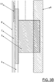
- FIG. 3B shows a detail view of in FIG. 3A circled area of the speaker 1 according to the invention to the sound generator 3, so the woofer, around.
- the existing of solid surface front wall 6 has a thickness of 3mm.
- the air chamber or the air-tight space 7 has a depth of 5mm.
- the mounting wall 5 may for example have a thickness of 13mm and also be made of mineral material.
- the woofer 3 is anchored in this embodiment in the rear wall 8 of the housing and is additionally supported by the mounting wall 5.
- FIG. 4 shows a third embodiment of a speaker 1 with a housing 2, which is only partially shown. Again, the drawing is not necessarily true to scale. Shown is the front wall 6 of the speaker 1, applied to the back of the second sound generator exciter 10, 11, 13, 14, 15 and 16, in particular glued. The surface of the front wall is divided into three parts by means of a box-like structure 17. The box structure 17 becomes, for example glued or glued to the rear side of the front wall 6, or more generally expressed, materially connected. In this way, the three resulting parts of the front wall 6 are acoustically or acoustically decoupled from each other. The three exciters 10, 11 and 16 are here in the left part of the front wall 6 according to FIG.
- the middle part of the front wall 6 in this embodiment forms the loudspeaker vibration diaphragm 6 '.
- the first sound generator 3, here the woofer can be mounted vibration-decoupled in a rear wall of the box structure 17 and / or in a rear wall of the housing 2 (cf. the embodiments according to FIG Figures 2 or 3 ).
- two first sound generator or woofer 3 may be present in the middle part of the front wall, the two woofers 3 in turn may be separated by a divider 12 on the inside of the front wall 6 tontechnisch.
Abstract
Die vorliegende Erfindung betrifft einen Lautsprecher (1) mit einem Gehäuse (2) und einem ersten Schallerzeuger (3), wobei der erste Schallerzeuger (3) in einer Befestigungswand (5) gehaltert ist und diese Befestigungswand (5) mit einer auf einer schallerzeugenden Seite des ersten Schallerzeugers (3) und zu diesem beabstandet liegenden Vorderwand (6) des Gehäuses (2) einen luftdichten Raum (7) begrenzt, und wobei zumindest ein Teil der Vorderwand (6) eine Schwingungsmembran (6') des Lautsprechers (1) bildet und dieser Teil der Vorderwand (6) mit dem übrigen Gehäuse (2) des Lautsprechers (1) starr verbunden ist.The present invention relates to a loudspeaker (1) comprising a housing (2) and a first sound generator (3), the first sound generator (3) being mounted in a mounting wall (5) and said mounting wall (5) being mounted on a sound generating side the first sound generator (3) and spaced front wall (6) of the housing (2) defines an airtight space (7), and wherein at least a part of the front wall (6) forms a vibration diaphragm (6 ') of the loudspeaker (1) and this part of the front wall (6) is rigidly connected to the rest of the housing (2) of the loudspeaker (1).
Description
Die vorliegende Erfindung betrifft einen Lautsprecher mit einem Gehäuse und einem ersten Schallerzeuger. Außerdem betrifft die vorliegende Erfindung eine Schwingungsmembran für einen Lautsprecher.The present invention relates to a loudspeaker having a housing and a first sound generator. Moreover, the present invention relates to a vibration diaphragm for a loudspeaker.
Lautsprecher an sich sind aus dem Stand der Technik bekannt. Aufbau und zugrunde liegende Technik sollen deshalb hier nicht im Detail erörtert werden. Lautsprecher enthalten sogenannte Schallerzeuger, die in der Regel mit einer Schwingungsmembran ausgestattet sind, um die vom Schallerzeuger erzeugten Schallwellen an das umgebende Medium (Luft) abzugeben. Solche Schallerzeuger existieren für den tiefen, mittleren und hohen Frequenzbereich, wobei der Frequenzbereich der Musikwahrnehmbarkeit von etwa 40 Hz bis etwa 8.000 kHz reicht.Speakers themselves are known in the art. The structure and underlying technology should therefore not be discussed in detail here. Loudspeakers contain so-called sound generators, which are usually equipped with a vibration membrane in order to deliver the sound waves generated by the sound generator to the surrounding medium (air). Such sound generators exist for the low, mid, and high frequency ranges, with the frequency range of music perceptibility ranging from about 40 Hz to about 8,000 kHz.
Zum Aufbau eines Lautsprechers können Schallerzeuger jeweils mit Schwingungsmembran in einer geeigneten Lautsprecherbox untergebracht werden. Neuere Lösungen, insbesondere auch für den Heimkinobereich, sehen häufig einen Subwoofer (Bassbox) vor, der zur Erzeugung von Schallfrequenzen im tieffrequenten Bereich konzipiert ist. Da derartige Schallquellen für das menschliche Gehör kaum zu lokalisieren sind, ist eine Aufstellung solcher Subwoofer an einem beliebigen Ort im Raum möglich. Um tiefe Töne zu erzeugen, muss allerdings eine möglichst große Menge Luft bewegt werden, wozu Subwoofer entweder einen Schallerzeuger mit einer möglichst großen Membranfläche einsetzen oder aber einen Schallerzeuger einsetzen, dessen Membranfläche mit großer Amplitude ausgelenkt werden kann. Die Signalversorgung eines Subwoofers erfolgt über eine Lautsprecherweiche, die aus den Signalen für die Schallerzeuger die niederfrequenten Anteile filtert und anschließend an den Schallerzeuger des Subwoofers weiterleitet, während die übrigen Anteile an die restlichen Schallerzeuger weitergeleitet werden.For the construction of a loudspeaker sound generators can each be accommodated with a vibration diaphragm in a suitable loudspeaker box. Recent solutions, especially for the home cinema sector, often provide a subwoofer (bass box), which is designed to generate sound frequencies in the low-frequency range. Since such sound sources for human hearing are difficult to localize, a list of such subwoofer in any place in the room is possible. In order to produce low tones, however, the largest possible amount of air has to be moved, for which subwoofers either use a sound generator with the largest possible membrane area or else one Insert sound generator whose membrane surface can be deflected with large amplitude. The signal is supplied to a subwoofer via a loudspeaker switch, which filters the low-frequency components from the signals for the sound generators and then forwards them to the sound generator of the subwoofer, while the other components are forwarded to the remaining sound generators.
Des Weiteren sind sogenannte Exciter bekannt, die membranlose Schallerzeuger darstellen. Sie verwenden ein festes Objekt als "Membran", wozu ein Exciter an einem solchen Objekt fixiert wird, das er in Schwingung versetzt. Solche Exciter werden überwiegend im Bereich der Soundmöbel eingesetzt. Sie lassen sich beispielsweise unter Tische, in Schränke, in Decken etc. kleben und agieren somit als unsichtbarer Lautsprecher.Furthermore, so-called exciters are known that represent membraneless sound generators. They use a solid object as a "membrane", for which purpose an exciter is fixed to such an object that it vibrates. Such exciters are mainly used in the field of sound furniture. For example, they can be stuck under tables, in cabinets, in ceilings, etc., thus acting as an invisible loudspeaker.
Andere Soundmöbel (auch Audiomöbel oder Medienmöbel genannt) verwenden abgedeckte herkömmliche Lautsprechersysteme im Inneren eines Möbels.Other sound furniture (also called audio furniture or media furniture) use covered conventional speaker systems inside a piece of furniture.
Der bisher bekannte Stand der Technik bringt mehrere Nachteile mit sich. Subwoofer sind häufig große, unhandliche Geräte, die viel Raum benötigen. Von den Subwoofern getrennt müssen Hoch- und Mitteltöner im Raum aufgestellt werden. Hiermit sind meistens lange Kabelwege verbunden. Kabellose Systeme funktionieren bislang nicht ohne Einbußen bei der Übertragungs- und/oder Hörqualität. Die Tonqualität von Möbel mit daran direkt aufgeklebten Exciter hängt stark von der Fläche, von der Geometrie sowie vom Aufbau und vom Material des jeweiligen Möbels ab. Insbesondere stören Verklebungen, Verleimungen, Fugen etc. die Schallausbreitung und wirken sich stark auf die Tonqualität aus.The hitherto known state of the art has several disadvantages. Subwoofers are often large, unwieldy devices that require a lot of space. Separated from the subwoofers, high and midrange speakers must be placed in the room. This usually involves long cable runs. Wireless systems have not worked without sacrificing transmission and / or listening quality. The sound quality of furniture with directly attached exciters depends strongly on the surface, the geometry as well as the structure and the material of the respective furniture. In particular, bonding, gluing, joints, etc. disturb the sound propagation and have a strong effect on the sound quality.
Aus dem Stand der Technik sind außerdem sogenannte "passive Strahler" bekannt.Also known from the prior art are so-called "passive radiators".
Beispielsweise schlägt die
Aus der
Passive Strahler bilden somit in einer Gehäusewand oder in einer Zwischenwand innerhalb des Gehäuses eines Lautsprechers schwingungsentkoppelt montierte Schallerzeuger oder Schwingungsmembrane, die durch einen als Treiber wirkenden Schallerzeuger in Schwingung versetzt werden.Passive radiators thus form in a housing wall or in an intermediate wall within the housing of a loudspeaker vibrationally decoupled sound generator or vibration diaphragm, which are set in vibration by a sound generator acting as a driver.
Derartige passive Strahler haben bei der vorliegend insbesondere betrachteten Verwendung eines Lautsprechers als Soundmöbel den Nachteil, dass ein in einer sichtbaren Vorderwand des Lautsprecher-Gehäuses montierter passiver Strahler die Stabilität der Gehäusevorderwand verringert. Derjenige Teil der Vorderwand, der den passiven Strahler bildet, ist mechanisch wenig belastbar und reagiert auf Druck, Schläge oder dergleichen empfindlich. Zudem bestehen hierdurch in bestimmten Verwendungen des Soundmöbels ästhetische Nachteile.Such passive radiators have in the presently considered particular use of a speaker as a sound furniture the disadvantage that a mounted in a visible front wall of the speaker housing passive radiator reduces the stability of the housing front wall. The part of the front wall that forms the passive radiator is mechanically less resilient and sensitive to pressure, shock or the like. In addition, this is in certain uses of sound furniture aesthetic disadvantages.
Es ist daher wünschenswert, einen Lautsprecher anzugeben, der die oben genannten Nachteile größtenteils überwindet und sich insbesondere zum Einsatz als Soundmöbel eignet.It is therefore desirable to provide a loudspeaker which largely overcomes the above-mentioned disadvantages and is particularly suitable for use as sound furniture.
Ein erfindungsgemäßer Lautsprecher weist ein Gehäuse und (mindestens) einen ersten Schallerzeuger auf, wobei der erste Schallerzeuger in einer Befestigungswand gehaltert ist und diese Befestigungswand mit einer auf einer schallerzeugenden Seite des ersten Schallerzeugers und zu diesem beabstandet liegenden Vorderwand des Gehäuses einen luftdichten Raum begrenzt. Hierbei bildet zumindest ein Teil der Vorderwand eine Schwingungsmembran des Lautsprechers, die mit dem Gehäuse des Lautsprechers starr verbunden ist. Der erste Schallerzeuger kann auch als Luftschallwandler bezeichnet werden.An inventive loudspeaker has a housing and (at least) a first sound generator, wherein the first sound generator is mounted in a mounting wall and limits this mounting wall with a front side wall of the housing spaced apart on a sound-generating side of the first sound generator and an airtight space. Here, at least a part of the front wall forms a vibration diaphragm of the loudspeaker, which is rigidly connected to the housing of the loudspeaker. The first sound generator may also be referred to as an airborne sound transducer.
Die Befestigungswand und die Vorderwand des Lautsprechers können im Wesentlichen parallel zueinander verlaufen. Beide Wände begrenzen einen luftdichten Raum, der an den übrigen Seiten insbesondere von dem Gehäuse des Lautsprechers begrenzt wird. Der (erste) Schallerzeuger wird durch die Befestigungswand gehalten und gibt insbesondere über eine eigene Schwingungsmembran Schallwellen in den luftdicht abgeschlossenen Raum ab. Die Schallwellen breiten sich zur Vorderwand des Gehäuses aus und versetzen diese ihrerseits in Schwingung, so dass die Vorderwand (oder zumindest ein Teil dieser Vorderwand) die Schwingungsmembran des Lautsprechers bildet. Erfindungsgemäß lässt sich somit die schallübertragende Fläche um einen Faktor vergrößern, der dem Verhältnis der Fläche der durch die Vorderwand gebildeten Schwingungsmembran des Lautsprechers zu der Fläche der Schwingungsmembran des Schallerzeugers entspricht. Auf diese Weise kann die effektive Fläche der Schwingungsmembran des Lautsprechers um ein Vielfaches im Vergleich zur tatsächlichen Fläche der Schallerzeuger-Schwingungsmembran erhöht werden, wodurch insbesondere im Tiefenfrequenzbereich sich eine weitaus bessere Tonqualität erzielen lässt als mit bekannten Lösungen des Standes der Technik.The mounting wall and the front wall of the speaker may be substantially parallel to each other. Both walls define an airtight space, which is bounded on the other sides in particular by the housing of the speaker. The (first) sound generator is held by the mounting wall and, in particular via its own vibration membrane from sound waves in the hermetically sealed space. The sound waves propagate to the front wall of the housing and vibrate them in turn, so that the front wall (or at least part of this front wall) the vibration membrane of the speaker. Thus, according to the invention, the sound-transmitting surface can be increased by a factor corresponding to the ratio of the area of the vibration diaphragm of the loudspeaker formed by the front wall to the surface of the vibration diaphragm of the sound generator. In this way, the effective area of the vibrating diaphragm of the loudspeaker can be increased many times as compared with the actual area of the sound generator vibrating diaphragm, whereby a much better sound quality can be achieved especially in the low frequency range than with known solutions of the prior art.
Erfindungsgemäß ist der die Schwingungsmembran des Lautsprechers bildende Teil der Vorderwand des Gehäuses mit dem Gehäuse starr oder steif verbunden. Im Gegensatz zu den in der Beschreibungseinleitung behandelnden passiven Strahlern handelt es sich hier nicht um eine schwingungsentkoppelte Befestigung. Vielmehr bildet der als Schwingungsmembran des Lautsprechers fungierende Teil der Vorderwand zusammen mit der Vorderwand eine solide Fläche, wobei es besonders vorteilhaft ist, wenn die gesamte Vorderwand des Gehäuses des Lautsprechers die Schwingungsmembran bildet. Der als Schwingungsmembran wirkende Teil der Vorderwand ist mit dem Rest des Gehäuses reib-, stoff- und/oder formschlüssig verbunden oder kann auch einstückig ausgeführt sein. Eine stoffschlüssige Verbindung, insbesondere durch Verkleben, hat sich als besonders vorteilhaft erwiesen. Es ist beispielsweise möglich, die Vorderwand des Gehäuses als einstückige solide Fläche, die starr und steif mit dem restlichen Gehäuse verbunden ist, auszuführen. In diesem Fall kann beispielsweise die gesamte Vorderwand als Schwingungsmembran des Lautsprechers dienen. Das Gehäuse bildet dann zusammen mit der Vorderwand einen stabilen Verbund, sodass der erfindungsgemäße Lautsprecher in besonders geeigneter Weise als Soundmöbel eingesetzt werden kann.According to the invention, the vibration membrane of the speaker forming part of the front wall of the housing with the housing is rigid or rigid. In contrast to the passive radiators treated in the introduction to the description, this is not a vibration-decoupled attachment. Rather, forms the part of the front wall functioning as a vibration diaphragm of the speaker together with the front wall a solid surface, it being particularly advantageous if the entire front wall of the housing of the speaker forms the vibration membrane. The acting as a vibration member part of the front wall is frictionally, material and / or positively connected to the rest of the housing or may also be made in one piece. A cohesive connection, in particular by gluing, has proved to be particularly advantageous. For example, it is possible to make the front wall of the housing a one-piece solid surface that is rigidly and rigidly connected to the rest of the housing. In this case, for example, the entire front wall can serve as a vibration diaphragm of the speaker. The housing then forms a stable composite together with the front wall, so that the loudspeaker according to the invention can be used in a particularly suitable manner as sound furniture.
Der Einfachheit halber soll - soweit nicht anders angegeben - von dem Fall ausgegangen werden, dass die gesamte Vorderwand die Schwingungsmembran des Lautsprechers bildet. In diesem Fall überträgt somit die Vorderseite des als Soundmöbel eingesetzten erfindungsgemäßen Lautsprechers den Schall in den Raum. Im Vergleich zur bisher bekannten Exciter-Technik ist die Tonqualität aber um ein Vielfaches höher, da nicht ein Exciter die Vorderseite des Gehäuses direkt in Schwingung versetzt, sondern ein vergleichsweise kleiner Lautsprecher (Schallerzeuger mit Schwingungsmembran in der Befestigungswand) die Schallwellen über den luftdicht abgeschlossenen Raum auf die große Fläche der Vorderwand überträgt. Diese Vorderwand bildet hierbei gleichzeitig die Schwingungsmembran des Lautsprechers und einen Teil des Möbels, wie ein Panel, ein Bild, eine Schrankwand, eine Schiebetür oder dergleichen.For the sake of simplicity, it should be assumed, unless stated otherwise, of the case that the entire front wall of the vibration membrane of Speaker forms. In this case, the front side of the loudspeaker according to the invention used as sound furniture thus transmits the sound into the room. Compared to the previously known exciter technology, however, the sound quality is many times higher, because not an exciter directly sets the front of the housing in vibration, but a relatively small speaker (sound generator with vibration membrane in the mounting wall) the sound waves over the hermetically sealed space transfers to the large area of the front wall. In this case, this front wall simultaneously forms the vibration diaphragm of the loudspeaker and part of the furniture, such as a panel, an image, a wall unit, a sliding door or the like.
Es ist insbesondere vorteilhaft, wenn der genannte Faktor, also das Verhältnis der Fläche der durch die Vorderwand (oder zumindest einem Teil derselbigen) gebildeten Schwingungsmembran zu der Fläche der eigentlichen Schallerzeuger-Schwingungsmembran mindestens 2,0, weiter insbesondere 4,0 oder 5,0 oder 10 oder 20 bis etwa 25 oder 30 beträgt. Insbesondere bevorzugt sind Verhältnisse von 4 bis 10. Dadurch, dass beide schwingenden Flächen über den luftdichten Raum gekoppelt sind, lässt sich hierdurch erfindungsgemäß eine starke Vergrößerung der effektiv an die Umgebung schallübertragenden Fläche erzielen.It is particularly advantageous if said factor, ie the ratio of the area of the vibration membrane formed by the front wall (or at least a part thereof) to the surface of the actual sound generator vibration membrane, is at least 2.0, more particularly 4.0 or 5.0 or 10 or 20 to about 25 or 30. In particular, ratios of 4 to 10 are preferred. Due to the fact that both oscillating surfaces are coupled via the airtight space, it is possible according to the invention to achieve a high magnification of the surface which effectively transmits sound to the surroundings.
Die Vorderwand ist, wie weiter unten noch zu erläutern sein wird (zumindest zum Teil) aus einem schwingungsfähigen geeigneten Material gefertigt. Es ist vorteilhaft, wenn die gesamte Vorderwand oder zumindest der größte Teil der Vorderwand die Schwingungsmembran des erfindungsgemäßen Lautsprechers bildet.The front wall is, as will be explained below (at least in part) made of a suitable material capable of vibrating. It is advantageous if the entire front wall or at least the largest part of the front wall forms the vibration diaphragm of the loudspeaker according to the invention.
Der in der Befestigungswand gehalterte erste Schallerzeuger ist insbesondere ein Luftschallwandler (Tieftöner) zur Erzeugung von Schallfrequenzen in einem ersten Frequenzbereich, insbesondere im Bereich von 25 Hz bis 600 Hz.The first sound generator mounted in the mounting wall is, in particular, an airborne sound transducer (woofer) for generating sound frequencies in a first frequency range, in particular in the range from 25 Hz to 600 Hz.
Es ist insbesondere von Vorteil, wenn der in der Befestigungswand gehalterte erste Schallerzeuger Schallwellen nur an den luftdichten Raum abgibt, ohne die Befestigungswand selbst in Schwingung zu versetzen (schwingungsentkoppelte Verbindung). Hierzu kann der Schallerzeuger schwingend in der Befestigungswand aufgenommen sein und zwar in einer Weise, dass möglichst wenig Schwingung auf die Befestigungswand selbst übertragen wird. Des Weiteren kann die Halterung (aus einem ersten Material) in eine Befestigungswand (aus einem zweiten steifen Material) integriert werden. Auch eine einteilige Ausführung ist möglich, wobei die Befestigungswand eine vergleichsweise hohe Materialstärke, insbesondere im Vergleich zur Vorderwand, besitzt, sodass sie kaum in Schwingung versetzt wird.It is particularly advantageous if the first sound generator mounted in the mounting wall emits sound waves only to the airtight space without vibrating the mounting wall itself (vibration-decoupled connection). For this purpose, the sound generator can be accommodated swinging in the mounting wall and indeed in such a way that as little vibration as possible is transmitted to the mounting wall itself. Furthermore, the holder (made of a first material) can be integrated into a mounting wall (made of a second rigid material). A one-piece design is also possible, wherein the mounting wall has a comparatively high material thickness, in particular in comparison to the front wall, so that it is hardly vibrated.
Es hat sich im Rahmen der Erfindung als besonders vorteilhaft gezeigt, wenn der die Schwingungsmembran bildende Teil der Vorderwand des Lautsprechers aus einem Mineralwerkstoff gefertigt ist. Bei solchen Mineralwerkstoffen handelt es sich um mineralisch-organische Verbundwerkstoffe, wie sie beispielsweise unter dem Namen Corian auf dem Markt sind. Corian besteht zu etwa 66 Gew.-% aus einer Modifikation von Aluminiumhydroxid sowie aus etwa 33 Gew.-% aus Polymethylmethacrylat (PMMA) sowie aus Katalysatoren und anderen Härtungsmittel. Allgemein kann ein hier verwendeter Mineralwerkstoff etwa 40 % (± 10%) gemahlenen Stein bzw. Marmor und etwa 60% (±10%) Acryl enthalten. Das Material ähnelt äußerlich dem Marmor, ist jedoch leichter, lässt sich fräsen und schneiden, aber auch dreidimensional thermisch verformen. Insbesondere lässt es sich fugenlos verbinden und wird bislang hauptsächlich im Sanitärbereich, in Küchen, Labors und Operationsräumen als Arbeitsflächen verwendet. Überraschenderweise hat sich herausgestellt, dass sich derartige Mineralwerkstoffe besonders gut als Membran insbesondere auch bei erfindungsgemäßen Lautsprechern eignen. Entsprechend dünne (insbesondere dünner als 5, 4, 3 oder 2 mm) Mineralwerkstoffplatten können die Vorderwand des Gehäuses eines erfindungsgemäßen Lautsprechers bilden, wobei sich herausgestellt hat, dass die Mineralwerkstoffplatte in besonders guter Weise zur Schallübertragung an den umgebenden Raum geeignet ist. Hierfür verantwortlich dürfte insbesondere der fugenlose Werkstoff sein, der sich gleichzeitig in großer Fläche und sehr dünn herstellen lässt. Vergleichbare auf dem Markt erhältliche Mineralwerkstoffe sind Hi-Macs oder Varicor.It has been found in the invention to be particularly advantageous if the vibration membrane forming part of the front wall of the speaker is made of a mineral material. Such mineral materials are mineral-organic composites, as they are for example under the name Corian on the market. Corian consists of about 66 wt .-% of a modification of aluminum hydroxide and about 33 wt .-% of polymethyl methacrylate (PMMA) and of catalysts and other curing agents. Generally, a mineral material used herein may contain about 40% (± 10%) ground stone or marble and about 60% (± 10%) acrylic. Externally, the material resembles marble, but is lighter, can be cut and cut, but also thermally deformed three-dimensionally. In particular, it can be joined seamlessly and has hitherto been used mainly in sanitary areas, in kitchens, laboratories and operating theaters as work surfaces. Surprisingly, it has been found that such mineral materials are particularly well suited as a membrane, especially in loudspeakers according to the invention. Correspondingly thin (in particular thinner than 5, 4, 3 or 2 mm) mineral material panels may form the front wall of the housing of a loudspeaker according to the invention, wherein it has been found that the solid surface panel is particularly well suited for sound transmission to the surrounding space. Responsible in particular for this is probably the jointless material, which itself can be produced simultaneously in a large area and very thin. Similar mineral materials available on the market are Hi-Macs or Varicor.
Es ist zweckmäßig, wenn das Gehäuse des Lautsprechers eine Rückwand aufweist, die auf der der Vorderwand abgewandten Seite der Befestigungswand und beabstandet zu dieser Befestigungswand liegt. Wiederum liegen insbesondere Rückwand und Befestigungswand im Wesentlichen parallel zu einander. Somit weist das Gehäuse in dieser Ausführungsform eine Rückwand und eine Vorderwand auf, wobei die Befestigungswand als Zwischenwand im Inneren des Gehäuses liegt.It is useful if the housing of the speaker has a rear wall which lies on the side facing away from the front wall of the mounting wall and spaced from this mounting wall. Again, in particular the rear wall and mounting wall are substantially parallel to each other. Thus, in this embodiment, the housing has a back wall and a front wall, wherein the mounting wall is located as an intermediate wall in the interior of the housing.
Es ist vorteilhaft, wenn mindestens zwei weitere Schallerzeuger ("zweite Schallerzeuger") innerhalb des Gehäuses jeweils mit einer schallerzeugenden Seite mit der Vorderwand des Gehäuses schallleitend verbunden sind. Bei diesen zweiten Schallerzeugern handelt es sich insbesondere um in der Beschreibungseinleitung bereits behandelte Exciter zur Erzeugung von Schallfrequenzen in einem zweiten Frequenzbereich. Dieser zweite Frequenzbereich grenzt insbesondere an den ersten Frequenzbereich an bzw. überlappt mit diesem und reicht insbesondere von 500 Hz bis 20.000 Hz.It is advantageous if at least two further sound generators ("second sound generators") within the housing each have a sound-generating side connected in a sound conducting manner to the front wall of the housing. These second sound generators are in particular exciters already discussed in the introduction to the introduction of sound frequencies in a second frequency range. This second frequency range, in particular, adjoins or overlaps the first frequency range and in particular ranges from 500 Hz to 20,000 Hz.
Solche Exciter können schallleitend in einfacher Weise (beispielsweise durch Kleben) mit der Vorderwand des Gehäuses, also der Schwingungsmembran des erfindungsgemäßen Lautsprechers, verbunden werden. Eine gerade Anzahl von Excitern, insbesondere zwei oder vier Exciter, hat sich als besonders vorteilhaft erwiesen.Such exciters can sound conducting in a simple manner (for example, by gluing) with the front wall of the housing, so the vibration of the speaker according to the invention, are connected. An even number of exciters, in particular two or four exciters, has proven to be particularly advantageous.
Insbesondere verläuft zwischen zwei der zweiten Schallerzeuger eine auf der Vorderwand befindliche Materialverstärkung. Bei vier solcher zweiten Schallerzeuger verläuft die Materialverstärkung somit insbesondere zwischen jeweils zwei Schallerzeugern, so dass die Materialverstärkung die Vorderwand in zwei Teile teilt, in denen jeweils zwei zweite Schallerzeuger liegen. Analoges gilt für eine andere geradzahlige Anzahl von zweiten Schallerzeugern (Excitern). Die Materialverstärkung bewirkt eine Kanaltrennung, wodurch es zu dem bekannten Stereoeffekt kommt.In particular, a material reinforcement located on the front wall extends between two of the second sound generators. In the case of four such second sound generators, the material reinforcement therefore extends in particular between two sound generators, so that the material reinforcement divides the front wall into two parts, in each of which two second sound generators are located. The same applies to another even number of second sound generators (exciters). The material reinforcement causes a channel separation, which leads to the known stereo effect.
Weiterhin ist vorteilhaft, wenn nicht nur jeweils ein Teil der mindestens zwei weiteren zweiten Schallerzeuger mittels einer Materialverstärkung von dem anderen Teil der mindestens zwei weiteren zweiten Schallerzeuger akustisch getrennt ist, sondern wenn darüber hinaus die weiteren zweiten Schallerzeuger von dem eine Schwingungsmembran des Lautsprechers bildenden Teil der Vorderwand des Gehäuses des Lautsprechers akustisch durch eine Materialverstärkung getrennt sind. Diese Ausgestaltung wird in einem Ausführungsbeispiel im Zusammenhang mit einer Figur weiter unten behandelt.Furthermore, it is advantageous if not only a respective part of the at least two further second sound generators is acoustically separated from the other part of the at least two further second sound generators by means of a material amplification, but if, in addition, the further second sound generators are part of the part forming the oscillation membrane of the loudspeaker Front wall of the housing of the speaker are acoustically separated by a material reinforcement. This embodiment is treated in an embodiment in connection with a figure below.
Es hat sich als vorteilhaft herausgestellt, wenn die Materialverstärkung zwischen zwei gegenüberliegenden Seiten der Vorderwand verläuft. Insbesondere sollte(n) die Materialverstärkung(en) hierbei die Vorderwand etwa in gleich große Flächenteile teilen. Es hat sich insbesondere als vorteilhaft erwiesen, wenn die Materialverstärkung mit einer dieser gegenüberliegenden Seiten einen Winkel von 80° bis 90°, insbesondere von 80° bis 85°, weiter insbesondere etwa 85°, einschließt. Hierdurch entstehen bei einer rechteckigen Vorderwand trapezförmige Flächenteile. Diese leichte Asymmetrie bewirkt, dass Eigenfrequenzen effektiv unterdrückt werden.It has proven to be advantageous if the material reinforcement extends between two opposite sides of the front wall. In particular, the material reinforcement (s) in this case should divide the front wall approximately in equal parts of the surface. It has proven to be particularly advantageous if the material reinforcement with one of these opposite sides an angle of 80 ° to 90 °, in particular from 80 ° to 85 °, more particularly about 85 °, includes. This results in a rectangular front wall trapezoidal surface parts. This slight asymmetry causes natural frequencies to be effectively suppressed.
Die Materialverstärkung bildet insbesondere einen Steg bzw. eine stegartige Materialverstärkung. Hierbei hat es sich als vorteilhaft erwiesen, wenn der Steg in seiner Abmessung senkrecht zur Vorderseite jeweils zu seinen beiden Enden hin abnimmt. Dies lässt sich insbesondere dadurch erreichen, dass der Steg in Längsrichtung einen kreisbogenförmigen Querschnitt hat. Derartig geformte Stege bewirken eine tontechnisch günstige Kanaltrennung, insbesondere für den Frequenzbereich oberhalb 1.000 Hz.The material reinforcement forms in particular a web or a web-like material reinforcement. It has proven to be advantageous if the web decreases in its dimension perpendicular to the front in each case to its two ends. This can be achieved in particular in that the web has a circular arc-shaped cross-section in the longitudinal direction. Such shaped webs cause a tontechnisch favorable channel separation, especially for the frequency range above 1,000 Hz.
Alternativ wird die Materialverstärkung durch insbesondere von hinten auf die Vorderwand des Gehäuses insbesondere senkrecht auf die Vorderwand stehende Flächen gebildet. Diese Flächen können beispielsweise Teil eines Kasten- oder Regalsystems sein, wobei die Vorderkanten dieses Systems mit der Vorderwand des Lautsprecher-Gehäuses verleimt beziehungsweise verklebt sein können. Diese Ausgestaltung wird weiter unten in einer Ausführungsform der Erfindung näher erläutert.Alternatively, the material reinforcement is formed in particular by the rear of the front wall of the housing in particular perpendicular to the front wall surfaces. These surfaces may be part of a box or shelf system, for example, wherein the leading edges of this system can be glued or glued to the front wall of the speaker housing. This embodiment will be explained in more detail below in an embodiment of the invention.
Bezüglich einiger Abmessungen einer möglichen Ausführungsform des erfindungsgemäßen Lautsprechers (siehe auch Ausführungsbeispiel gemäß
Das oben genannte Beispiel eines erfindungsgemäßen Lautsprechers verdeutlicht seine Eignung als Soundmöbel. Hierbei ist die als Schwingungsmembran dienende Vorderwand ausreichend stabil, da die Vorderwand eine ausreichende Materialstärke besitzen kann. Dies ist ein großer Vorteil gegenüber Schwingungsmembrane bzw. passive Strahler gemäß Stand der Technik, die häufig unter 1 mm Materialstärke besitzen bzw. federnd im Gehäuse angebracht sind. Derartige Materialstärken bzw. federnde Gehäuseteile wären aufgrund ihrer geringen Belastbarkeit für den Gebrauch als Möbel wenig geeignet. Der oben beispielhaft beschriebene Lautsprecher kann eine Rückwand aufweisen, die beabstandet zur Befestigungswand liegt, wobei der Abstand insbesondere 30 bis 60 mm betragen kann. Insgesamt entsteht hierdurch ein Panel, das beispielsweise als Bild oder als Wandelement dienen kann. Es sei darauf hingewiesen, dass dieses beschriebene Beispiel keinerlei einschränkende Wirkung für den erfindungsgemäßen Lautsprecher besitzen soll. Insbesondere sind sämtliche Geometrien der Lautsprechervorderwand, beispielsweise auch runde, ovale oder mehreckige, denkbar. Die genannten Bemaßungen sind bei anderen Größen und/oder Geometrien vom Fachmann geeignet zu wählen bzw. anzupassen.The above example of a speaker according to the invention illustrates its suitability as a sound furniture. Here, the serving as a vibration membrane front wall is sufficiently stable, since the front wall can have sufficient material thickness. This is a great advantage over vibration membranes or passive radiators according to the prior art, which are often less than 1 mm in thickness and are mounted resiliently in the housing. Such material thicknesses or resilient housing parts would be less suitable for use as furniture due to their low load capacity. The loudspeaker described above by way of example may have a rear wall which is at a distance from the mounting wall, wherein the distance may be in particular 30 to 60 mm. Overall, this creates a panel that can serve as an image or wall element, for example. It should be noted that this described example is not intended to have any limiting effect on the loudspeaker according to the invention. In particular, all the geometries of the loudspeaker front wall, for example also round, oval or polygonal, are conceivable. The dimensions mentioned are suitable for other sizes and / or geometries to be selected or adapted by a person skilled in the art.
Gemäß einem weiteren Aspekt der vorliegenden Erfindung wird eine Schwingungsmembran für einen Lautsprecher vorgeschlagen, wobei die Schwingungsmembran aus einem Mineralwerkstoff gefertigt ist. Die Eigenschaften von Mineralwerkstoffen sowie Beispiele solcher Mineralwerkstoffe sind oben angegeben und ausführlich diskutiert. Überraschenderweise hat sich gezeigt, dass solche Mineralwerkstoffe bei hinreichend geringer Werkstoffdicke auch als Schwingungsmembran geeignet sind. Insbesondere ein Einsatz bei Soundmöbel ist hier vorteilhaft. Die Materialdicke sollte zwischen 1 mm und 5 mm, insbesondere 2 bis 4 mm, insbesondere 3 mm betragen. Aufgrund der Homogenität und Fugenfreiheit von Mineralwerkstoffplatten sind diese optimal als Schwingungsmembran geeignet.According to a further aspect of the present invention, a vibration diaphragm for a loudspeaker is proposed, wherein the vibration diaphragm is made of a solid surface material. The properties of mineral materials and examples of such mineral materials are given above and discussed in detail. Surprisingly, it has been found that such mineral materials are also suitable as a vibration membrane with sufficiently low material thickness. In particular, use in sound furniture is advantageous here. The material thickness should be between 1 mm and 5 mm, in particular 2 to 4 mm, in particular 3 mm. Due to the homogeneity and gap-free nature of mineral composite panels, they are optimally suited as a vibration membrane.
Der Einsatz einer solchen Mineralwerkstoff-Schwingungsmembran als oder in einer Vorderwand eines oben beschriebenen erfindungsgemäßen Lautsprechers ist besonders bevorzugt.The use of such a mineral material vibration membrane as or in a front wall of a loudspeaker according to the invention described above is particularly preferred.
Es versteht sich, dass die vorstehend genannten und die nachstehend noch zu erläuternden Merkmale nicht nur in der jeweils angegebenen Kombination, sondern auch in anderen Kombinationen oder in Alleinstellung verwendbar sind, ohne den Rahmen der vorliegenden Erfindung zu verlassen.It is understood that the features mentioned above and those yet to be explained below can be used not only in the particular combination given, but also in other combinations or in isolation, without departing from the scope of the present invention.
Die Erfindung ist anhand eines Ausführungsbeispieles in der Zeichnung schematisch dargestellt und wird im Folgenden unter Bezugnahme auf die Zeichnung beschrieben.The invention is illustrated schematically with reference to an embodiment in the drawing and will be described below with reference to the drawing.
-
Figur 1 zeigt eine Durchsicht durch eine erste Ausführungsform eines erfindungsgemäßen Lautsprechers, betrachtet mit Blick auf dessen Vorderseite, mit dessen wesentlichsten Elementen,FIG. 1 3 shows a view through a first embodiment of a loudspeaker according to the invention, looking at its front side, with its essential elements, -
Figur 2 zeigt schematisch den erfindungsgemäßen Lautsprecher ausFigur 1 in Querschnitt entlang der Linie AA ausFigur 1 ,FIG. 2 schematically shows the speaker according to the inventionFIG. 1 in cross section along the line AAFIG. 1 . -
Figur 3 zeigt schematisch einen Vertikalschnitt durch eine zweite Ausführungsform eines erfindungsgemäßen Lautsprechers (Figur 3A ), wobei inFigur 3B eine Detailansicht gezeigt ist, undFIG. 3 schematically shows a vertical section through a second embodiment of a loudspeaker according to the invention (FIG. 3A ), where inFIG. 3B a detail view is shown, and -
Figur 4 zeigt eine Durchsicht durch eine dritte Ausführungsform eines erfindungsgemäßen Lautsprechers, betrachtet mit Blick auf dessen Vorderseite, mit dessen wesentlichsten Elementen.FIG. 4 shows a view through a third embodiment of a loudspeaker according to the invention, looking at the front, with its most essential elements.
In der Durchsicht gemäß
Der Tieftöner 3 ist seinerseits nicht an der Vorderwand 6 angeordnet, sondern an einer eigenen Befestigungswand 5, wie anhand von
In
Bezüglich beispielhafter Bemessungen des in den
Der Lautsprecher 1 weist ein Gehäuse 2 auf. Die Vorderwand ist wiederum mit 6 bezeichnet. Die Exciter 10 und 11 sind schematisch im Querschnitt dargestellt. Der Tieftöner 3 wird von einer Befestigungswand 5 derart gehaltert, dass möglichst keine Schwingung auf die Befestigungswand 5 übertragen wird. Zur Vermeidung von Schwingungen kann die Befestigungswand 5 auch mit entsprechend hoher Materialstärke und/oder aus einem entsprechenden Material gefertigt sein. Bezüglich möglicher Materialien und Bemessungen sei wiederum auf das oben ausgeführte Beispiel verwiesen. Der Tieftöner 3 gibt Schwingungen niedriger Frequenz, insbesondere zwischen 25 und 600 Hz über die Schwingungsmembran 4 an den luftdichten Raum 7 ab. Der Raum 7 ist in diesem Beispiel mit Luft gefüllt. Auch andere Fluide, insbesondere Gase zur Füllung des Raums 7 sind denkbar. Insbesondere können durch bestimmte Fluide bzw. Gase Schallfrequenzen in eine bestimmte Richtung verschoben werden. Der luftdichte Raum 7 wird von der Vorderwand 6, von der Befestigungswand 5 sowie vom übrigen Gehäuse 2 gebildet. Hinter der Befestigungswand 5 ist eine Rückwand 8 angeordnet, die Teil des Gehäuses 2 ist.The
Das hier dargestellte Beispiel eines Lautsprechers 1 eignet sich besonders gut als Soundmöbel oder als Bestandteil eines Möbels, beispielsweise als Panel oder als Bestandteil einer Theke, einer Tür oder einer Wand. Bei einer etwas weniger tiefen Ausführung kann der Lautsprecher 1 auch als Bild eingesetzt werden, wenn die Vorderwand 6 bemalt oder bedruckt ist.The example of a
Im hier dargestellten Ausführungsbeispiel wird als Material der Vorderwand 6 der Mineralwerkstoff Corian bei einer Materialstärke von ca. 2 bis 4 mm verwendet. Als Material der Befestigungswand 5 bietet sich eine Aluminiumplatte oder ebenfalls eine Mineralwerkstoffplatte an. Zu möglichen Bemessungen sei wieder auf das oben Gesagte verwiesen.In the embodiment shown here is used as the material of the
Schließlich sei noch angemerkt, dass die in
Ein weiteres Ausführungsbeispiel eines erfindungsgemäßen Lautsprechers 1 ist in
Im Vertikalschnitt gemäß
In diesem Ausführungsbeispiel weist die aus Mineralwerkstoff bestehende Vorderwand 6 eine Dicke von 3mm auf. Die Luftkammer bzw. der luftdichte Raum 7 besitzt eine Tiefe von 5mm. Die Befestigungswand 5 kann beispielsweise eine Stärke von 13mm aufweisen und ebenfalls aus Mineralwerkstoff gefertigt sein. Der Tieftöner 3 ist in dieser Ausführungsform in der Rückwand 8 des Gehäuses verankert und wird zusätzlich von der Befestigungswand 5 gehaltert.In this embodiment, the existing of solid surface
In einer weiteren von der Ausführungsform gemäß
- 11
- Lautsprecherspeaker
- 22
- Gehäusecasing
- 33
- erster Schallerzeuger, Tieftönerfirst sound generator, woofer
- 44
- Schallerzeuger-SchwingungsmembranSound generator-vibrating diaphragm
- 55
- Befestigungswandmounting wall
- 66
- Vorderwandfront wall
- 6'6 '
- Lautsprecher-SchwingungsmembranSpeaker vibrating diaphragm
- 77
- luftdichter Raumairtight room
- 88th
- Rückwandrear wall
- 99
- Frequenzweichecrossover
- 1010
- Exciter, zweiter SchallerzeugerExciter, second sound generator
- 1111
- Exciter, zweiter SchallerzeugerExciter, second sound generator
- 1212
- Trennstegdivider
- 1313
- Exciter, zweiter SchallerzeugerExciter, second sound generator
- 1414
- Exciter, zweiter SchallerzeugerExciter, second sound generator
- 1515
- Exciter, zweiter SchallerzeugerExciter, second sound generator
- 1616
- Exciter, zweiter SchallerzeugerExciter, second sound generator
- 1717
- Kastenstrukturbox structure
Claims (21)
Applications Claiming Priority (1)
| Application Number | Priority Date | Filing Date | Title |
|---|---|---|---|
| DE102015205658.9A DE102015205658B4 (en) | 2015-03-27 | 2015-03-27 | speaker |
Publications (1)
| Publication Number | Publication Date |
|---|---|
| EP3073761A1 true EP3073761A1 (en) | 2016-09-28 |
Family
ID=55586227
Family Applications (1)
| Application Number | Title | Priority Date | Filing Date |
|---|---|---|---|
| EP16161140.5A Withdrawn EP3073761A1 (en) | 2015-03-27 | 2016-03-18 | Loudspeaker |
Country Status (2)
| Country | Link |
|---|---|
| EP (1) | EP3073761A1 (en) |
| DE (1) | DE102015205658B4 (en) |
Cited By (1)
| Publication number | Priority date | Publication date | Assignee | Title |
|---|---|---|---|---|
| DE102021122597A1 (en) | 2021-09-01 | 2023-03-02 | Synotec Psychoinformatik Gmbh | Mobile immersive 3D audio space |
Families Citing this family (1)
| Publication number | Priority date | Publication date | Assignee | Title |
|---|---|---|---|---|
| DE202020005845U1 (en) | 2019-01-18 | 2022-10-13 | Hommbru Gmbh | Loudspeaker module for integration into a furniture body |
Citations (7)
| Publication number | Priority date | Publication date | Assignee | Title |
|---|---|---|---|---|
| DE534412C (en) * | 1926-11-25 | 1931-09-26 | Siemens & Halske Akt Ges | Device for generating or recording mechanical, in particular acoustic vibrations, the vibrating parts of which (e.g. membranes) are manufactured using pulverulent minerals |
| DE3709700A1 (en) * | 1987-03-25 | 1988-10-13 | Meggl Friedemann | SPEAKER HOUSING |
| US4783820A (en) * | 1985-01-03 | 1988-11-08 | Lyngdorf Johan P | Loudspeaker unit |
| US5147986A (en) * | 1990-12-03 | 1992-09-15 | Tandy Corporation | Subwoofer speaker system |
| DE4446690A1 (en) | 1993-12-28 | 1995-06-29 | Mitsubishi Electric Corp | Composite loudspeaker arrangement and method for controlling it |
| DE69533649T2 (en) | 1994-09-01 | 2006-02-23 | Matsushita Electric Industrial Co., Ltd., Kadoma | woofer |
| US20070081687A1 (en) * | 2005-10-07 | 2007-04-12 | Yamaha Corporation | Speaker system |
Family Cites Families (4)
| Publication number | Priority date | Publication date | Assignee | Title |
|---|---|---|---|---|
| JPS63254894A (en) * | 1987-04-11 | 1988-10-21 | Takeshi Teragaki | Planar speaker |
| US6188775B1 (en) * | 1995-09-02 | 2001-02-13 | New Transducers Limited | Panel-form loudspeakers |
| AT414199B (en) * | 2004-12-27 | 2006-10-15 | Gansterer Peter | SPEAKER MEMBRANE WITH STEEL RIBBON STRUCTURE |
| CN104285453A (en) * | 2012-05-08 | 2015-01-14 | 哈曼(中国)投资有限公司 | A new speaker |
-
2015
- 2015-03-27 DE DE102015205658.9A patent/DE102015205658B4/en not_active Expired - Fee Related
-
2016
- 2016-03-18 EP EP16161140.5A patent/EP3073761A1/en not_active Withdrawn
Patent Citations (7)
| Publication number | Priority date | Publication date | Assignee | Title |
|---|---|---|---|---|
| DE534412C (en) * | 1926-11-25 | 1931-09-26 | Siemens & Halske Akt Ges | Device for generating or recording mechanical, in particular acoustic vibrations, the vibrating parts of which (e.g. membranes) are manufactured using pulverulent minerals |
| US4783820A (en) * | 1985-01-03 | 1988-11-08 | Lyngdorf Johan P | Loudspeaker unit |
| DE3709700A1 (en) * | 1987-03-25 | 1988-10-13 | Meggl Friedemann | SPEAKER HOUSING |
| US5147986A (en) * | 1990-12-03 | 1992-09-15 | Tandy Corporation | Subwoofer speaker system |
| DE4446690A1 (en) | 1993-12-28 | 1995-06-29 | Mitsubishi Electric Corp | Composite loudspeaker arrangement and method for controlling it |
| DE69533649T2 (en) | 1994-09-01 | 2006-02-23 | Matsushita Electric Industrial Co., Ltd., Kadoma | woofer |
| US20070081687A1 (en) * | 2005-10-07 | 2007-04-12 | Yamaha Corporation | Speaker system |
Non-Patent Citations (1)
| Title |
|---|
| BAUMEISTER: "Minimalistischer Klangkörper - Baumeister", 23 January 2015 (2015-01-23), XP055289746, Retrieved from the Internet <URL:https://www.baumeister.de/minimalistischer-klangkoerper-hommbru/#IMM-Koeln-Hommbru-631x440> [retrieved on 20160719] * |
Cited By (2)
| Publication number | Priority date | Publication date | Assignee | Title |
|---|---|---|---|---|
| DE102021122597A1 (en) | 2021-09-01 | 2023-03-02 | Synotec Psychoinformatik Gmbh | Mobile immersive 3D audio space |
| EP4144928A1 (en) | 2021-09-01 | 2023-03-08 | Synotec Psychoinformatik GmbH | Mobile immersive 3d audio space |
Also Published As
| Publication number | Publication date |
|---|---|
| DE102015205658A1 (en) | 2016-09-29 |
| DE102015205658B4 (en) | 2017-03-16 |
Similar Documents
| Publication | Publication Date | Title |
|---|---|---|
| DE69533649T2 (en) | woofer | |
| DE2815051A1 (en) | CLOSED HEADPHONES | |
| DE3404655A1 (en) | Device for transmitting pressure waves | |
| DE2836937A1 (en) | HEADPHONE | |
| DE2536439A1 (en) | SPEAKER SYSTEM | |
| DE6809798U (en) | SPEAKER BOX. | |
| DE102016124084B4 (en) | Loudspeaker system with directional effect | |
| EP0125625A1 (en) | Loudspeaker box with integrated band-pass filter | |
| DE102013011696A1 (en) | Variable device for aligning sound wave fronts | |
| DE1166269B (en) | Low frequency speaker system | |
| DE102015205658B4 (en) | speaker | |
| DE102015104478B4 (en) | Flat speaker | |
| DE3201455C2 (en) | Speaker box | |
| DE60208245T2 (en) | Speaker System | |
| DE102008013627B4 (en) | speaker | |
| EP1142445B1 (en) | Low-frequency diaphragm speaker | |
| DE19639159A1 (en) | Speaker box | |
| DE1291790B (en) | Loudspeaker box with one or more loudspeakers | |
| EP1965602B1 (en) | Speaker | |
| DE3233990C2 (en) | Methods and devices for improved reproduction of phantom sound sources | |
| DE102015215429A1 (en) | Arrangement for holding a device and device | |
| DE945768C (en) | Loudspeaker group arrangement consisting of several loudspeakers built in a row in a common baffle-like baffle | |
| DE202012103862U1 (en) | Acoustic device and audio system with selfsame | |
| EP1718101A2 (en) | Loudspeaker | |
| DE3130789C2 (en) | Loudspeaker box with acoustically in-phase coupled drivers with simultaneous use of the rear sound components |
Legal Events
| Date | Code | Title | Description |
|---|---|---|---|
| PUAI | Public reference made under article 153(3) epc to a published international application that has entered the european phase |
Free format text: ORIGINAL CODE: 0009012 |
|
| AK | Designated contracting states |
Kind code of ref document: A1 Designated state(s): AL AT BE BG CH CY CZ DE DK EE ES FI FR GB GR HR HU IE IS IT LI LT LU LV MC MK MT NL NO PL PT RO RS SE SI SK SM TR |
|
| AX | Request for extension of the european patent |
Extension state: BA ME |
|
| STAA | Information on the status of an ep patent application or granted ep patent |
Free format text: STATUS: THE APPLICATION HAS BEEN PUBLISHED |
|
| STAA | Information on the status of an ep patent application or granted ep patent |
Free format text: STATUS: THE APPLICATION IS DEEMED TO BE WITHDRAWN |
|
| 18D | Application deemed to be withdrawn |
Effective date: 20170329 |