EP3028640A2 - Needle guide devices for mounting on imaging transducers or adaptors on imaging transducer, imaging transducers for mounting needle guide devices and adaptors for imaging transducers for mounting needle guide devices thereon - Google Patents
Needle guide devices for mounting on imaging transducers or adaptors on imaging transducer, imaging transducers for mounting needle guide devices and adaptors for imaging transducers for mounting needle guide devices thereon Download PDFInfo
- Publication number
- EP3028640A2 EP3028640A2 EP15003185.4A EP15003185A EP3028640A2 EP 3028640 A2 EP3028640 A2 EP 3028640A2 EP 15003185 A EP15003185 A EP 15003185A EP 3028640 A2 EP3028640 A2 EP 3028640A2
- Authority
- EP
- European Patent Office
- Prior art keywords
- needle
- guide device
- needle guide
- barrel
- slide
- Prior art date
- Legal status (The legal status is an assumption and is not a legal conclusion. Google has not performed a legal analysis and makes no representation as to the accuracy of the status listed.)
- Granted
Links
- 238000003384 imaging method Methods 0.000 title claims abstract description 122
- 230000008878 coupling Effects 0.000 claims abstract description 105
- 238000010168 coupling process Methods 0.000 claims abstract description 105
- 238000005859 coupling reaction Methods 0.000 claims abstract description 105
- 230000007246 mechanism Effects 0.000 claims description 12
- 238000004891 communication Methods 0.000 claims description 8
- 238000012800 visualization Methods 0.000 claims description 4
- 230000035515 penetration Effects 0.000 abstract description 11
- 238000002604 ultrasonography Methods 0.000 description 20
- 239000000523 sample Substances 0.000 description 12
- 239000000463 material Substances 0.000 description 10
- 210000005069 ears Anatomy 0.000 description 8
- 239000004033 plastic Substances 0.000 description 8
- 238000000034 method Methods 0.000 description 7
- 238000010276 construction Methods 0.000 description 6
- 230000009471 action Effects 0.000 description 5
- 238000001574 biopsy Methods 0.000 description 5
- 230000008859 change Effects 0.000 description 5
- 241001465754 Metazoa Species 0.000 description 3
- 206010028980 Neoplasm Diseases 0.000 description 3
- 230000001154 acute effect Effects 0.000 description 3
- 238000006073 displacement reaction Methods 0.000 description 3
- 230000000694 effects Effects 0.000 description 3
- 239000003086 colorant Substances 0.000 description 2
- -1 e.g. Substances 0.000 description 2
- 238000003780 insertion Methods 0.000 description 2
- 230000037431 insertion Effects 0.000 description 2
- 239000004816 latex Substances 0.000 description 2
- 229920000126 latex Polymers 0.000 description 2
- 238000012986 modification Methods 0.000 description 2
- 230000004048 modification Effects 0.000 description 2
- 241000748691 Furia Species 0.000 description 1
- 241000282412 Homo Species 0.000 description 1
- 238000013459 approach Methods 0.000 description 1
- 238000011109 contamination Methods 0.000 description 1
- 230000000593 degrading effect Effects 0.000 description 1
- 238000002059 diagnostic imaging Methods 0.000 description 1
- 230000001079 digestive effect Effects 0.000 description 1
- 238000007667 floating Methods 0.000 description 1
- 239000012530 fluid Substances 0.000 description 1
- 210000001035 gastrointestinal tract Anatomy 0.000 description 1
- 239000002991 molded plastic Substances 0.000 description 1
- 210000005000 reproductive tract Anatomy 0.000 description 1
- 230000001954 sterilising effect Effects 0.000 description 1
- 238000004659 sterilization and disinfection Methods 0.000 description 1
- 230000001225 therapeutic effect Effects 0.000 description 1
Images


Classifications
-
- A—HUMAN NECESSITIES
- A61—MEDICAL OR VETERINARY SCIENCE; HYGIENE
- A61B—DIAGNOSIS; SURGERY; IDENTIFICATION
- A61B17/00—Surgical instruments, devices or methods, e.g. tourniquets
- A61B17/34—Trocars; Puncturing needles
- A61B17/3403—Needle locating or guiding means
-
- A—HUMAN NECESSITIES
- A61—MEDICAL OR VETERINARY SCIENCE; HYGIENE
- A61B—DIAGNOSIS; SURGERY; IDENTIFICATION
- A61B8/00—Diagnosis using ultrasonic, sonic or infrasonic waves
- A61B8/08—Detecting organic movements or changes, e.g. tumours, cysts, swellings
- A61B8/0833—Detecting organic movements or changes, e.g. tumours, cysts, swellings involving detecting or locating foreign bodies or organic structures
- A61B8/0841—Detecting organic movements or changes, e.g. tumours, cysts, swellings involving detecting or locating foreign bodies or organic structures for locating instruments
-
- A—HUMAN NECESSITIES
- A61—MEDICAL OR VETERINARY SCIENCE; HYGIENE
- A61B—DIAGNOSIS; SURGERY; IDENTIFICATION
- A61B8/00—Diagnosis using ultrasonic, sonic or infrasonic waves
- A61B8/44—Constructional features of the ultrasonic, sonic or infrasonic diagnostic device
- A61B8/4444—Constructional features of the ultrasonic, sonic or infrasonic diagnostic device related to the probe
- A61B8/4455—Features of the external shape of the probe, e.g. ergonomic aspects
-
- A—HUMAN NECESSITIES
- A61—MEDICAL OR VETERINARY SCIENCE; HYGIENE
- A61B—DIAGNOSIS; SURGERY; IDENTIFICATION
- A61B17/00—Surgical instruments, devices or methods, e.g. tourniquets
- A61B17/34—Trocars; Puncturing needles
- A61B17/3403—Needle locating or guiding means
- A61B2017/3405—Needle locating or guiding means using mechanical guide means
-
- A—HUMAN NECESSITIES
- A61—MEDICAL OR VETERINARY SCIENCE; HYGIENE
- A61B—DIAGNOSIS; SURGERY; IDENTIFICATION
- A61B17/00—Surgical instruments, devices or methods, e.g. tourniquets
- A61B17/34—Trocars; Puncturing needles
- A61B17/3403—Needle locating or guiding means
- A61B2017/3413—Needle locating or guiding means guided by ultrasound
Definitions
- This invention relates generally to needle guides for medical imaging instruments and more particularly to devices for guiding needles into selected locations of a patient relative to a medical instrument imaging sensor.
- Imaging instruments such as ultrasound probes
- These medical instruments utilize substantially non-invasive imaging techniques to explore and assess the condition of human tissue.
- diagnostic and therapeutic protocols have been developed that allow many highly successful and safe procedures to be performed with a minimum of disturbance to patients.
- ultrasound probes have become an accepted modality for exploring endocavities, e.g., the human digestive and reproductive tracts, of humans and animals in order to conduct routine examinations, as well as to identify evidence of tumors.
- these tumors can be located and assessed.
- biopsy samples may be taken by carefully directing a hand-held needle, such as a biopsy instrument, catheter, or other thin instrument (hereafter referred to collectively as “needle” or “needles”) into the body of a patient in order to remove a tissue sample. It is normally desirable that the needle be guided to a specific position within the body.
- hand-held direction of a needle is often inadequate, being both inaccurate and time consuming.
- various needle guide devices have been designed for use with ultrasonic probes or other imaging transducers to assist in directing needles during imaging analysis.
- Some of the needle guides disclosed in the aforementioned patents and some commercially available needle guides are designed to be mounted on an ultrasonic probe or other imaging instrument that is itself enclosed within a sterile cover, such as a film. These covers serve to maintain the ultrasound sensor in a sterile environment, while reducing the likelihood of contamination between patients and also reduce the cost of medical procedures by minimizing sterilization costs.
- prior art needle guides typically have some portion which projects a substantial distance laterally outward from the transducer to establish that trajectory. That projecting portion creates a "blind" spot or zone by hiding or otherwise obscuring a portion of the patient's body from direct viewing by the user.
- a need also exists for a needle guide device that can establish a trajectory angle close to the image plane, without any portion of it projecting greatly outward laterally from the transducer to thereby minimize the size of any blind spot that could result.
- the subject invention also addresses that need.
- an adjustable needle guide device that: (1) is configured to permit the user to change the trajectory angle trajectory of the needle after the needle guide has been mounted on the transducer and also to change the trajectory angle of the needle while the needle is disposed within the needle guide; (2) is configured to enable the user to select desired predetermined needle trajectory angles corresponding to guidelines overlaid on the ultrasound system; (3) permits the user to utilize a "freehand" approach, i.e., to adjust the needle trajectory angle to any desired angle, to maintaining the needle within the ultrasound image plane of the transducer; and (4) is configured to enable the user to change the trajectory angle at any time, e.g., before introduction of the needle into the needle guide device or after the needle has been inserted therein.
- the subject invention also addresses those needs.
- a needle guide device configured for releasable mounting on an imaging transducer or on an adaptor on an imaging transducer.
- the imaging transducer or the adaptor each includes a coupling member comprising a first portion.
- the needle guide device comprises a lockable mounting member and a needle guide assembly.
- the needle guide assembly comprises a body member and a needle holder.
- the needle holder is mounted on the body member and comprises an elongated passageway for receipt of a needle to establish the trajectory of the needle when the needle is located therein.
- the lockable mounting member comprises a slidable member having a second portion. One of the first portion and the second portion comprises a projection, and the other of the first portion and the second portion comprises a recess.
- the slidable member is configured to be slidably coupled to the body member and slidable from an unlocked position to a locked position and vice versa.
- the projection is configured for receipt in the recess to releasably secure the slidable member to the imaging transducer or the adaptor when the slidable member is in the locked position, thereby releasably mounting the needle guide device on the imaging transducer.
- the needle holder is adjustably mounted on the body member to enable the needle holder to be oriented to various selected orientations, e.g., from approximately 0° to approximately 40° degrees, with respect to the body member to establish various angled trajectories for the needle.
- the needle holder is oriented at a predetermined fixed angle with respect to the body member to establish a desired angled trajectory for the needle.
- the slidable member comprises a portion of a lockable mounting assembly.
- the lockable mounting assembly comprises a body member including a stop. The stop is configured to engage the slidable member when the slidable member is in the locked position, whereupon the coupling member is held between the stop and the second portion of the slidable member.
- a needle guide device configured for mounting on an imaging transducer or on an adaptor on an imaging transducer.
- the needle guide device comprises a base member, a barrel member, a slide member and a needle holder.
- the needle holder is mounted on the barrel member and comprises an elongated passageway for receipt of a needle to establish the trajectory of the needle when the needle is located therein.
- the barrel member is pivotably mounted on the base member.
- the slide member is slidable with respect to the base member and coupled to the barrel member to pivot the barrel member with respect to the base member to a first angular orientation when the slide member is slid to a first position, and to pivot the barrel portion with respect to the base member to a second angular orientation when the slide member is slid to a second position.
- the needle holder establishes a first angular trajectory for the needle when the barrel member is in the first angular orientation and establishes a second angular trajectory for the needle when the barrel member is in the second angular orientation.
- the second angular trajectory is different than the first angular trajectory.
- the needle guide assembly comprises a base member, a needle holder subassembly and a slide member.
- the needle holder subassembly comprises a barrel member and the needle holder.
- the needle holder is located in the barrel member and comprises an elongated passageway for receipt of a needle to establish the trajectory of the needle when the needle is located therein.
- the barrel member is pivotably mounted on the base member.
- the slide member is slidable with respect to the base member and coupled to the barrel member to pivot the barrel member with respect to the base member to a first angular orientation when the slide member is slid to a first position, and to pivot the barrel portion with respect to the base member to a second angular orientation when the slide member is slid to a second position.
- the needle holder establishes a first angular trajectory for the needle when the barrel member is in the first angular orientation and establishes a second angular trajectory for the needle when the barrel member is in the second angular orientation.
- the second angular trajectory is different than the first angular trajectory.
- the barrel member comprises a cylindrical cavity having a central longitudinal axis and wherein the needle holder comprises an elongated cylindrical member located within the cylindrical cavity and rotatable about the central longitudinal axis.
- the needle holder has a passageway extending therethrough parallel to the central longitudinal axis.
- the passageway is configured for receipt of the needle therein to establish the needle's trajectory.
- the barrel portion includes a slot in communication with the cylindrical cavity and extending parallel and to the central longitudinal axis.
- the needle holder comprises a slot in communication with the passageway.
- the needle holder is rotatable within the cylindrical cavity between a closed and open position, and vice versa.
- the slot in the needle holder is aligned with the slot in the barrel when the needle holder is rotated to the open position.
- a needle extending through the passageway can be removed from the needle holder laterally through the aligned slots and a needle can be introduced into the passageway laterally through the aligned slots.
- the slots are unaligned when the needle holder is in the closed position, whereupon a needle disposed in the passageway is held therein.
- an imaging transducer for providing a signal representing an image of an internal portion of the body of a patient for visualization by a user of the imaging transducer.
- the imaging transducer has a housing comprising a coupling member for enabling the releasable securement of a needle guide device thereto.
- the needle guide device comprises a lockable mounting member having a second portion.
- the coupling member comprises a first portion.
- One of the first portion and the second portion comprises a projection, and the other of the first portion and the second portion comprises a recess.
- the lockable mounting member is slidable from an unlocked position to a locked position with respect to the needle guide device, and vice versa.
- the projection is configured for receipt in the recess to releasably secure the lockable mounting member to the coupling member when the lockable mounting member is in the locked position, thereby releasably mounting the needle guide device on the imaging transducer.
- an adaptor for mounting on an imaging transducer.
- the imaging transducer is configured for providing a signal representing an image of an internal portion of the body of a patient for visualization by a user of the imaging transducer.
- the adaptor has a housing comprising a coupling member for enabling the releasable securement of a needle guide device thereto.
- the needle guide device comprises a lockable mounting member.
- the lockable mounting member has a second portion.
- the coupling member comprises a first portion. One of the first portion and the second portion comprises a projection, and the other of the first portion and the second portion comprises a recess.
- the lockable mounting member is slidable from an unlocked position to a locked position with respect to the needle guide device, and vice versa.
- the projection is configured for receipt in the recess to releasably secure the lockable mounting member to the coupling member when the lockable mounting member is in the locked position, thereby releasably mounting the needle guide device on the adaptor.
- Fig. 1 one exemplary preferred embodiment of a reusable needle guide device 20 constructed in accordance with this invention.
- Another preferred exemplary embodiment of a reusable needle guide device 20' constructed in accordance with this invention is shown in Fig. 18 .
- Still another reusable needle guide device 20" constructed in accordance with this invention is shown in Fig. 21 .
- Those three exemplary embodiments are configured to be releasably mounted directly on an imaging instrument, e.g., an ultrasound transducer or probe 10, or indirectly mounted on an adaptor bracket 200 constructed in accordance with this invention and shown in Figs. 13 and 25 , to guide a needle 12 or any other elongated instrument through a desired path or trajectory into the body of a patient (human or animal) for a tissue biopsy procedure or any number of other medical procedures.
- an imaging instrument e.g., an ultrasound transducer or probe 10
- an adaptor bracket 200 constructed in accordance with this invention and shown in Figs. 13 and 25
- the needle guide device 20 is adjustable, so that it can establish a trajectory path enabling the needle or instrument to reach an internal site in the patient's body that is close to or far away from the distal or working end of the transducer.
- the needle guide device 20 is configured to enable the user to adjust the needle angle trajectory through a wide range, e.g., a range of approximately 40 degrees.
- the needle guide device 20' of Fig. 18 and the needle guide device 20" of Fig. 21 are not adjustable. Rather, each establishes a fixed, different respective, trajectory angle for the needle or other instrument.
- a plurality of fixed angle needle guide devices like guides 20' and 20" can be provided in the form of a kit of several fixed needle guide devices, each establishing its own, and different, angled trajectory path.
- the user can establish the desired angular path for the needle or other instrument.
- the needle guide device is an adjustable angle or fixed angle device
- all of the needle guide devices of this invention make use of a mounting feature to enable them to be readily and quickly mounted on an imaging transducer 10, with a conventional cover 14 interposed therebetween.
- That cover is typically formed of a thin, flexible sheath of any suitable material, e.g., latex, into a suitable shape, e.g., condom-shaped sheath, to be placed over the imaging transducer before the needle guide device is mounted thereon to keep the transducer sanitary.
- cover has been omitted from many of the figures of the drawing, it being understood that the cover is, in fact, interposed between the needle guide device and the imaging transducer on which the needle guide device is mounted or interposed between the needle guide device and the adaptor bracket on which the needle guide is mounted.
- the exemplary needle guide devices 20, 20' and 20" include a locking member that is configured to be slidably releasably secured to a locating feature or coupling member that is provided on a specially constructed imaging transducer housing or is provided on a bracket or adapter for use on a conventional imaging transducer.
- the adjustable needle guide device 20 and the fixed needle guide device 20" (and all other needle guides constructed in accordance with subject invention), enable the user to establish a very shallow depth of penetration for a needle, with a minimal blind spot, since the needle guides do not include any portion which projects far out from the transducer to block the view of the user, i.e., all of the needle guide devices of this invention have a compact form factor.
- the needle guide device 20 basically comprises a needle guide assembly 22 and a lockable mounting member 24.
- the lockable mounting member is configured to be releasably secured to a universal or common locating feature or coupling member 16 that is located on the housing of the transducer adjacent the distal or working end of the transducer.
- the coupling member 16 is preferably mounted at the location of the typical "#1 array indicator" of a conventional ultrasonic transducer.
- the coupling member 16 is in the form of a projection of somewhat rectangular profile and having an enlarged top portion 16A and a pair of undercut recesses 16B on the opposed long sides of the projection.
- the lockable mounting member 24 is best seen in Figs. 6 and 7 and basically comprises a rectangularly shaped frame, e.g., an integrally molded plastic component, having one side section in the form of a thickened handle 26, a pair of intermediate sections 28 and 30 extending from respective ends of the handle section and an opposite side section 32 connected between the intermediate sections.
- a cross-piece section 34 extends parallel and closely adjacent the handle section.
- the cross piece includes a projection, e.g., a flange, 36 extending along the length thereof.
- the sections 26, 28, 30 and 32 define a window 38 therebetween.
- the window 38 is configured to receive the transducer's coupling member 16 and the portion of the cover 14 overlying the top16A of the coupling member when the guide device 20 is to be mounted on the transducer.
- the lockable mounting member 24 is configured to be slidably received within a slot or channel 62 (to be described later) forming a portion of the needle guide assembly 22 so that it can be slid by a user pushing on the handle from an open position wherein the coupling member is located within the window 38, to a locked position, and vice versa.
- the lockable mounting member In order to ensure that the lockable mounting member is held in the locked position so that it is resistant to accidental displacement, it includes a pair of extending fingers 40 projecting outward from the respective ends of its side section 32.
- Each finger 40 is connected to its respective end of the side section 32 by a short flexible bridge section 42, which engages a respective portion in the slot or channel 62 of the needle guide assembly to securely hold the lockable mounting member in the locked position.
- the bridge sections 42 being resilient, are effectively spring-biased so that they are configured to be flexed inward when the fingers 40 are squeezed together by a user. This brings the bridge sections 42 towards each other to thereby release the lockable mounting member 24 from its locked position.
- the lockable mounting member can be removed from the needle guide by squeezing the fingers 40 together after the transducer's coupling member 16 is out of the window 38 and then pulling on the handle 36 to pull the lockable mounting member out of the slot or channel 62.
- the needle guide assembly 22 basically comprises a body or base member 44, a needle holder subassembly 46 and a slide member 48. Each is molded of a suitable plastic material.
- the body member 44 comprises a generally flat panel having a pair of long sides 50A and 50B.
- a pair of triangularly shaped flanged ears 52A and 52B project rearwardly from the bottom portions of the sides 50A and 50B, respectively.
- Each ear includes a short slot terminating in a circular hole 54 for accommodating a respective pivot pin of a cylindrically shaped barrel member 56 (to be described shortly) forming a portion of the needle holder subassembly 46.
- the holes 54 are axially aligned.
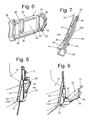
- a generally planar back wall 58 extends between the marginal edges of the triangular ears as best seen in Fig. 9 .
- the front portion of the body member 44 includes an arcuate recess or cavity 60, as best seen in Fig.8 , which is configured to accommodate the barrel member 56.
- the back wall 58 includes a slot or channel 62 extending from one side of the back wall to the other and is open to the back surface of the back wall from the ear 52A to a point adjacent the ear 52B.
- a central opening 64 is located in the front surface of the back wall and is shaped to accommodate the top portion 16A of the transducer coupling member 16 to releasably secure the needle guide device to the transducer.
- the barrel member 56 is an elongated generally tubular member having a centrally located front slot 66 extending parallel to the central longitudinal axis 78 of the barrel member.
- a pair of triangular ears 68 project outward from the barrel member 56 on opposite sides of the slot 66.
- Each ear includes a linear slot or track 70 (only one of which can be seen in the figures) which extends at an acute angle, e.g., 15°, from the longitudinal axis of the barrel member, and oriented upward and outward as shown in Figs. 2 and 8 - 12 .
- the bottom edge portion of the barrel member includes a pair of pivot pins 72 projecting outward therefrom.
- the pins 72 are diametrically opposed and axially aligned, and each pin is configured to be disposed within a respective hole 54 in the body member 44.
- the barrel member When so located the barrel member is able to pivot with respect to the body member about the axis of the aligned holes and pins to enable the barrel to assume any desired angular position with respect to the body member from 0° (as shown in Fig. 8) to 40 ° (as shown in Fig. 9 ).
- the means for effecting the pivoting of the barrel member with respect to the base member is the heretofore identified slide member 48.
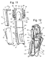
- a description of the member for holding the needle 12 in the needle guide device 20 is in order. That member is best seen in Figs. 10 and 11 . It is in the form of an elongated cylindrical needle holder or insert 74.
- the insert is molded of any suitable plastic material and is configured to be disposed within the barrel member 46 to directly hold the needle 12 therein.
- the insert 74 is configured to be rotated about the central axis 78 of the barrel member between an open position, such as shown in Fig. 12 , and a closed position, such as shown in Fig. 2 , and vice versa.
- the insert 74 has a slot 76 extending parallel to the central longitudinal axis 78 of the insert from one end of the insert to the other.
- the width of the slot 76 is just slightly larger than the diameter of the particular diameter needle 12 to be used with the needle guide device.
- the inner end 80 of the slot 76 extends parallel to the central longitudinal axis 78 and is circular in shape to accommodate the needle 12 therein.
- the depth of the slot i.e., the distance from the outer surface of the insert (and the inner surface of the barrel member) to the inner end of the slot is just slightly larger than the diameter of the needle.
- the upper or entrance end of the slot 76 is chamfered or tapered to facilitate the axial introduction of the needle therein, i.e., the tapered or chamfered surface directs the distal end of the needle towards the slot when the needle is introduced axially.
- a tab 82 projects radially outward from the top end of the insert to enable the user to rotate the insert 76 about central longitudinal axis 78 within the barrel member between the open and closed positions.
- the upper end of the barrel member has a pair of notches 84 immediately adjacent each side of the slot 66. The ends of the notches establish a pair of stops enabling the insert to be rotated through an angle of 180 degrees and no more.
- the needle 12 can be inserted laterally therein, instead of axially through the chamfered upper end of the insert as discussed above.
- the tab 82 is grasped by the user to rotate the insert 74 180° about central longitudinal axis 78 (which is also the longitudinal central axis of the barrel member) from the position shown in Figs. 1 and 2 to the position like shown in Fig. 12 .
- the slot 76 of the insert will be aligned with the slot 66 of the barrel member, whereupon the needle can be inserted laterally through the aligned slots.
- the tab 82 can be rotated 180° back to the closed position shown in Figs. 1 and 2 , thereby holding the needle in place.
- the imaging transducer 10 and needle guide device 20 can be freed (removed) from the needle leaving the needle 12 in place by merely rotating the insert 74 to its open position, like shown in Fig. 12 , whereupon the imaging transducer 10 and needle guide device 20 mounted thereon can be moved as a unit laterally with respect to the needle 12 so that the needle passes through the aligned slots 66 and 77.
- the slide member basically comprises a generally planar body section 86 having a thickened pair of side flanges 88, each of which includes a longitudinally extending slot or channel for receipt of a respective side edge 50A or 50B of the base member 44 to slidably mount the slide member thereon.
- the central portion of the body section includes a recess or cavity 90 to accommodate the barrel member 46 when it is in its 0° orientation, i.e., when the slot 76 of the needle holder mounted within the barrel member extends parallel to the plane of the slot 62 of the base member. That orientation is shown in Figs. 1 and 8 .
- a pair of ears 92 project outward perpendicularly from the bottom of the body section 86 on each side of the slot 90. Each ear terminates in a free end from which a pivot pin 94 projects.
- the pivot pins 94 are axially aligned and each is configured to be disposed within a respective one of the angularly extending tracks 70 of the barrel member.
- the exemplary embodiment of the variable angle needle guide device 20 shown herein includes a detent mechanism to hold the barrel member in any one of a number, e.g., seven, discrete distinct predetermined angular orientations with respect to the base member, so that the slide member can be readily and repeatedly slid to any one of those positions and to be held therein against accidental displacement therefrom.
- the detent mechanism basically comprises a plurality of pairs of notches 96 ( Figs. 10 and 11 ) extending along the sides 50A and 50B of the base member at various predetermined spaced locations therealong and which are configured to be engaged by pair of fingers on the slide member to releasably hold the slide member at the position established by the pair of notches into which the fingers have been disposed.
- the slide member 48 includes a pair of pivotable arms 98 mounted on the side flanges 88.
- the upper end of each arm 98 is in the form of a handle and a lower portion in the form of an inwardly directed free end finger 100.
- Each arm is mounted on a respective one of the side flanges by a flexible bridge section 102, whereupon when the handles 98 are squeezed together the flexible bridge sections 102 flex to cause the two opposed fingers 100 to move apart from each other.
- That action frees the pair of fingers 100 from whatever pair of notches 96 they had been located in so that the slide member 48 can then be slid to any other position with respect to the base member 44, whereupon the pair of fingers are aligned with the pair of notches at that new position.
- the handles 98 can then be released, causing them to snap back to bring the fingers into those notches to releasably secure the slide in that position.
- the device 20 includes indicia to provide an indication of the angle to which the needle guide has been set.
- the needle guide includes a plurality of letters, in this exemplary case the letters A through G, located on the front surface of the base member 44.
- the notches associated with the letters A - G establish the angles of 45°, 35°, 25°, 20°, 15°, 10°, and 5°, respectively.
- the indicia may be in the form of numerical indicia directly identifying the angle, e.g., indicia stating "40°", or numerical indicia representing a particular angle.
- the indicia may be in the form of different colors representing different angles or some other indicia representing different angles.
- the top edge portion of the body section 86 includes a pair of windows 104 ( Fig. 10 ) which are configured to expose the particular indicia, e.g., in this example the letters A - G, associated with the pair of notches 96 in which the pair of fingers 100 are located.
- the user of the device can press on the handles 98 of the slide member to free its fingers from the base member so that the slide member can be slid with respect to the base member until one of windows 104 exposes the letter (or other indicia) associated with the desired angle for the needle.
- the handles can then be released to enable the arms to spring back, whereupon the fingers enter the associated notches, thereby releasably locking the slide in that desired position.
- the needle guide device 20 as described above is configured so that the slide can be moved to any of the seven discrete positions established by the pairs of notches 96 to establish the angled needle trajectory associated with that pair of notches, the spring bias provided by the flexible bridge sections 102 will hold the free end of the fingers in sufficient frictional engagement with the side edges 50A and 5B of the base member between the notches 96.
- the slide member can be slid and held at a "free hand" position in between any of the notches. This feature is important to enable the user to establish a precise desired needle trajectory angle even if it isn't one of the pre-established angles defined by the pairs of notches.
- the needle guide 20 is configured to be directly mounted on an imaging transducer 10 which has been specially constructed or modified to include the heretofore described locating feature (e.g., coupling member 16).
- the needle guide devices of this invention are also suitable for use on conventional imaging transducers, i.e., imaging transducers without the locating feature or coupling member.
- the heretofore mentioned adaptor bracket constituting another aspect of this invention.
- the adaptor bracket 200 is best seen in Figs. 13 - 17 and enables a needle guide of this invention to be indirectly mounted on the prior art imaging transducer 10.
- the adaptor bracket 200 basically comprises a hollow housing 202 made of any suitable material, e.g., a plastic.
- the housing is hollow and shaped to accommodate the lower portion of whatever prior art imaging transducer it is to be used on.
- the housing 202 includes a front portion 204 and a rear portion 206 disposed opposite to the front portion.
- the bottom of the housing is open to expose the working end of the imaging transducer 10.
- the housing is split to enable the housing to be opened like a clamshell.
- the housing 202 includes a vertically oriented channel 208 extending from the top edge of the housing at the back portion to approximately the mid-height of the housing.
- the portion 210 of the housing 202 between the bottom of the channel 208 and the bottom edge of the housing forms the "hinge" of the clamshell arrangement.
- the front portion 204 of the housing is split in half from its top edge to its bottom edge by means of a top channel 212 and a bottom channel 214.
- the top channel merges with the bottom channel and is slightly wider than the top channel.
- the front portion of the housing 202 includes a coupling member 216.
- the coupling member 216 is constructed like the coupling member 16 described heretofore, except that it is split by the channel 214 into two halves.
- the coupling member 216 includes one half on one side of the channel 214 and the other half on the other side of that channel.
- the two half sections of the coupling member form of a projection of somewhat rectangular profile and having an enlarged top portion 116A and a pair of undercut recesses 116B on the opposed long sides of the projection, i.e., on one side of one half section and on the corresponding side of the other half section.
- the mounting of the adaptor bracket 200 can be readily accomplished by grasping portions of the front portion of the housing on opposite sides of the channel 212 to open that channel, whereupon the two portions of the housing on opposite sides of the channel can pivot open about hinge 210 so that the bottom portion of the conventional imaging transducer 10 can be placed between the two open halves of the housing, with the working end of the imaging transducer within the open bottom of the housing.
- the housing can then be released so that it snaps back into its normally closed state on the imaging transducer like shown in Fig. 14 .
- a cover 14 can then be placed over the adaptor bracket and the transducer.
- a needle guide device constructed in accordance with this invention can then be releasably mounted on the coupling member as described above with reference to the needle guide 20.
- any existing prior art imaging transducer can be readily retrofit by means of the adaptor 200 to accommodate the needle guide device 20 (or any other needle guide device making use of the lockable mounting member).
- Figs. 18 - 20 and 22 - 24 the details of the fixed angle needle guide device 20' will now be described. That device makes use of the same lockable mounting member 24 for releasable mounting on the same coupling member 16 or 216 as described heretofore.
- That device makes use of the same lockable mounting member 24 for releasable mounting on the same coupling member 16 or 216 as described heretofore.
- the needle guide device 20' basically comprises a needle guide assembly 122 and the lockable mounting member 24. Those components are each preferably molded of any suitable plastic material.
- the needle guide assembly 122 basically comprises a base member 126 having a slot or channel 128 extending through it from one side of the base member to the other side.
- the channel 128 is configured to slidably receive the lockable mounting member 24 in a manner similar to the slot or channel 62 in the adjustable needle guide device 20.
- the back surface of the base member 126 includes a recess 130.
- the coupling member 16 of the transducer With the lockable mounting member 24 in place within the slot or channel 128 in its open position, the coupling member 16 of the transducer, with a portion of the cover 14 overlying the top 16A of the coupling 16, can be extended through the recess 130 and through the window 38 in the lockable mounting member. Then the handle 26 of the lockable mounting member can be pushed inward to move the lockable mounting member to the locked position, whereupon the flanged projection 36 is located within the undercut recess 12B of the coupling member 16 or 216 to thereby releasably mounting the needle guide device 20' onto the imaging transducer or on the adaptor bracket with the cover 14 interposed therebetween.
- the needle guide assembly also includes a barrel member 132 and a needle holder 134.
- the barrel member 132 is an elongated generally tubular member having a slot 136 extending parallel to the central longitudinal axis 138 of the barrel member from the top of the barrel member to the bottom thereof.
- the barrel member is fixedly mounted on the base member 126 so that the longitudinal central axis 138 of the barrel member, which defines the needle trajectory, extends at a predetermined angle to the base member 126.
- the predetermined angle is 5° in relation to its mounting member 126.
- the predetermined angle is 45° in relation to its mounting member 126.
- the means for mounting the barrel member 132 in its particular angular orientation comprises a pair of arcuate struts 140 projecting outward from the base member 126.
- the needle holder 134 is in the form of an elongated cylindrical insert that is configured to be disposed within the barrel member 132 to directly hold the needle 12 therein. Moreover, the insert is configured to be rotated about the longitudinal central axis 138 of the barrel member between an open position, such as shown in Fig. 24 , and a closed position, such as shown in Figs. 18 and 20 , and vice versa.
- the elongated cylindrical insert has a slot 142 extending parallel to the central longitudinal axis of the insert from one end of the insert to the other. The width of the slot 142 is just slightly larger than the diameter of the particular diameter needle 12 to be used with the needle guide device 20'. The inner end of the slot 142 is circular in shape to accommodate the needle 12 therein.
- the depth of the slot i.e., the distance from the outer surface of the insert 134 (and the inner surface of the barrel member 132) to the inner end of the slot is just slightly greater than the diameter of the needle.
- the adjustable needle guide device 20 different inserts or needle holders can be provided with different size slots 142 to accommodate different diameter needles for use with a fixed angle needle guide device, like device 20'.
- the needle holder of device 20' makes use of a slot 142 whose upper end is chamfered to facilitate the axial introduction of the needle therein.
- a tab 144 projects radially outward from the top end of the insert 132 to enable the user to rotate the insert about central longitudinal axis 138 within the barrel member 134 between the open and closed positions, and vice versa.
- the upper end of the barrel member has an internal T-shaped slot having an elongated portion 146 extending about a portion of the periphery of the barrel member just below the top edge thereof and an entry portion 148 extending from the top edge to the elongated portion 146.
- the tab 144 includes a narrow section where the tab merges with the tubular insert and which is configured to be introduced through the entry portion 148 of the T-shaped slot and then into the elongated portion of that slot.
- the elongated portion of the T-shaped slot is of a sufficient length to enable the insert 132 to be rotated about an angle of approximately 180° between the closed position and the open position, and vice versa, when the tab 144 is within the elongated portion 146 of the slot.
- the needle 12 can be inserted therein laterally instead of axially through the chamfered upper end of the insert as discussed above.
- the tab is grasped by the user to rotate the insert 180° about central longitudinal axis 138 (which is also the longitudinal central axis of the barrel member) from the position like shown in Figs. 18 and 19 to the position like shown in Fig. 24 .
- the slot 142 of the insert will be aligned with the slot 136 of the barrel member, whereupon the needle 12 can be inserted laterally through the aligned slots.
- the tab 144 can be rotated 180 degrees back to the closed position shown in Figs. 18 and 19 , thereby holding the needle in place.
- the imaging transducer 10 and needle guide device 20' that is mounted thereon can be freed (removed) from the needle leaving the needle in place by merely rotating the insert 74 to its open position, like shown in Fig. 18 , whereupon the transducer and needle guide device can be moved as unit laterally with respect to the needle so that the needle passes through the aligned slots 136 and 142.
- Fig. 21 there is shown an alternative embodiment of a fixed angle needle guide device 20" constructed in accordance with this invention.
- the needle guide device 20" is virtually identical in construction to the needle guide device 20', except that it establishes a greater angled trajectory for the needle, i.e., a 40° angle with respect to the body member 126.
- the struts 140 are of a longer length, e.g., establish an angle of 40°.
- the common features of the embodiments of the devices 20' and 20" will be given the same reference numbers and the details of their construction and operation will not be reiterated.
- the subject invention contemplates providing a kit of plural fixed angle needle guide devices, like device 20' and 20" as well as others establishing other fixed angles desired for use.
- the fixed angle devices 20', 20' and any other fixed angle device are configured to be directly mounted on an imaging transducer which has been specially constructed or modified to include the heretofore described locating feature, e.g., the coupling member 16, and with a cover interposed therebetween.
- the bracket or adaptor 200 like shown in Fig. 14
- Fig. 25 shows a conventional imaging transducer 10 on which an adaptor 200, like that described above, has been mounted and over which a conventional cover 14 has been disposed.
- the fixed needle guide device 20" is releasably mounted to the coupling member 16 of the adaptor, with the cover interposed therebetween.
- the lockable mounting member of the needle guide device can make use of a recess, e.g., an undercut recess, while the coupling member can make use of a projection for slidable receipt in the recess of the lockable mounting member.
- the recess on the coupling member or the recess on the lockable mounting member need not be located as shown in the exemplary embodiment, e.g., on the sides of the coupling member, but can be in any suitable location to effect the slidable, releasably locking engagement between the coupling member and the lockable mounting member.
- the pivotable connection between the slide member and the barrel member can be reversed from the exemplary embodiment described above, i.e., the adjustable angle needle guide can make use of a barrel having at least one projecting fingers and a slide member having an ear with at least one angularly extending track or slot for receipt of the at least one finger.
- the pivotable connection between the slide member and the body member can be reversed from the exemplary embodiment described above, i.e., the barrel member can include a pair of aligned holes and the body member can include a pair of pins for receipt in the aligned holes to enable the barrel member to pivot thereabout.
- the common locating feature e.g., the coupling member
- the common locating feature can be applied to most general purpose ultrasound transducers. That common locating feature can be easily cleaned. Moreover, it is shaped similar to a #1 array indicator, so users of the invention should feel familiar with it. Moreover, the structure and arrangement of the common locating feature causes minimal interference or discomfort during scanning, yet provides stable support of for the needle guide device. Further still, the locating feature allows attachment without damaging an ultrasound cover. Insofar as the needle guide device is concerned, it enables one to fix the trajectory angle of the device and also allows for user selection of multiple trajectories.
- the device incorporates functionality where the user can change the needle trajectory angle before or after assembly to a transducer, bracket and/or insertion of the needle therein.
- the needle guide device provides visible indicia in the form of a character/number/identification element for each needle path trajectory, allowing the user to identify the trajectory and manually select the corresponding guidelines overlay on the ultrasound system.
- the needle guide devices enable the establishment of an angular range of at least 40° and can maintain a close proximity to the transducer to achieve a minimal "blind zone".
- the needle guide devices of this invention accept multiple versions of inserts sized for differing needle diameters.
- a needle guide device constructed in accordance with this invention exhibits a form factor that is minimal near the transducer lens so as not to interfere with scanning and has a sufficiently low profile without any fixed features that extend past the needle path.
- a reusable needle guide device 320 constructed in accordance with this invention is shown.
- the needle guide device 320 is configured to be releasably mounted directly on an imaging instrument, e.g., an ultrasound transducer or probe 10 like shown in Figs. 26 and 27 , or mounted on an adapter bracket 400 constructed in accordance with this invention and shown in Figs. 43 and 44 .
- an imaging instrument e.g., an ultrasound transducer or probe 10 like shown in Figs. 26 and 27
- an adapter bracket 400 constructed in accordance with this invention and shown in Figs. 43 and 44 .
- the device 320 when mounted on a transducer 10 or on an adaptor 400 which in turn is mounted on a transducer serves to mount and guide a needle 12 or any other elongated instrument through a desired path or trajectory into the body of a patient (human or animal) for a tissue biopsy procedure or any number of other medical procedures.
- the needle guide device 320 is adjustable, so that it can establish a trajectory path enabling the needle or instrument to reach an internal site in the patient's body that is close to or far away from the distal or working end of the transducer.
- the needle guide device 320 is configured to enable the user to adjust the needle angle trajectory through a wide range.
- the exemplary needle guide device 320 (and any other needle guide device constructed in accordance with this invention) makes use of a mounting feature to enable it to be readily and quickly mounted on an imaging transducer 10 either with or without a conventional cover 14 interposed therebetween. If a cover is used it will typically be formed of a thin, flexible sheath of any suitable material, e.g., latex, into a suitable shape, e.g., a condom-shaped sheath, to be placed over the imaging transducer before the needle guide device is mounted thereon to keep the transducer sanitary.
- a cover it will typically be formed of a thin, flexible sheath of any suitable material, e.g., latex, into a suitable shape, e.g., a condom-shaped sheath, to be placed over the imaging transducer before the needle guide device is mounted thereon to keep the transducer sanitary.
- the cover has been omitted from figures of the drawing of the embodiment 320, it being understood that the cover can be interposed between the needle guide device and the imaging transducer on which the needle guide device is mounted. Alternatively the cover can be interposed between the needle guide device and the adapter bracket on. In either such case the needle device can be releasably mounted without breaching the cover.
- the exemplary needle guide device 320 includes a lockable mounting assembly arranged to be releasably secured to a universal or common locating feature or coupling member that is provided on the housing of a specially constructed imaging transducer or on an adapter bracket for use on a conventional imaging transducer.
- the lockable mounting assembly includes a slidable member (e.g., a lock slide to be described later) that is configured to be slid from an unlocked position to enable the needle guide device to be mounted on the coupling member, to a locked position wherein the needle guide is releasably locked or secured to the coupling member and hence to the transducer.
- the needle guide device 320 (and all other needle guides constructed in accordance with subject invention) is configured to enable the user to adjust the angle of penetration for the needle between a minimum angle and a maximum angle.
- the needle guide device When adjusted to the maximum angle the needle guide device enables a very shallow depth of penetration for the needle, with a minimal blind spot, without any portion of the needle guide device projecting far out from the transducer to block the view of the user.
- the needle guide device 320 like other needle guide devices of this invention, has a compact form factor.
- the exemplary needle guide device 320 basically comprises a needle guide assembly 322 and a lockable mounting assembly 324.
- the lockable mounting assembly 324 is configured to be releasably secured to a universal or common locating coupling member 316 that is located on the housing of the transducer adjacent the distal or working end of the transducer.
- the coupling member 316 is preferably mounted at the location of the typical "#1 array indicator" of a conventional ultrasonic transducer.
- the common locating coupling member 316 is used on an adapter bracket 400, it will be located on that bracket at a position corresponding to the position that the coupling member is mounted on the transducer itself.
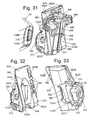
- the coupling member 16 is in the form of a projection of somewhat regular profile and having an enlarged generally planar front surface portion 316A, an undercut recesses 316B on the left side of the projection, an undercut recess 316C on the right side of the projection, and an undercut recess 316D on the top side of the projection.
- the undercut recess 316D slants downward symmetrically from the center of the top side towards the left side of the projection and also toward the right side of the projection.
- the lockable mounting assembly 324 is best seen in Figs. 32 - 36B and basically comprises a slidable member or lock slide 310 and a lock lever 312. Each is molded of a suitable plastic material.
- the lock slide 310 is a generally planar frame-like member having a generally linear side surface 310A and a pair of projecting ears 310B and 310C ( Fig. 34 ) located on opposite sides of the surface 310A.
- the surface 310A constitutes an engagement surface configured to mate with (be received within) the left side undercut recess 316C of the projection 316 when the lockable mounting assembly is in the locked position.
- the lock slide includes an opening 310D for receipt of portions of the lock lever 312 (to be described later).
- the lock slide is arranged for slidable receipt within an undercut slot 302 in a body or base member 304 of the needle guide device to enable the lock slide to be slid between the unlocked position (not shown) and the locked position ( Fig. 33 ), and vice versa.
- the body or base member 304 of the needle guide device forms a portion of the needle guide assembly 322.
- the undercut slot 302 includes short front edge surface 302A and an opposed pair of linear surfaces 302B and 302C which between them define the entryway to the undercut slot.
- the end of the slot opposite the slot's entryway is in the form of a generally planar, linear projection 306 overlying the slot.
- the ears 310B and 310C of the lock slide are configured to be introduced into the undercut slot by locating them within the portions of the slot contiguous with the surfaces 302B and 303C, respectively, and then sliding the lock slide towards projection 306.
- the projection 306 forms a stop surface which is configured to mate with (be received within) the right side undercut recess 316C of the coupling member (projection) 316 when the lockable mounting assembly is in the locked position, whereupon the projection 316 is tightly sandwiched between the engagement surface 310A and the stop surface 306.
- the means for sliding the lock slide 310 between the unlocked position and the locked position, and vice versa, is the heretofore identified lock lever 312.
- the lock lever 312 basically comprises a finger grip portion 312A, a pivot pin portion 312B ( Fig. 36B ), and a cam portion 312C.
- the pivot pin 312B is a split member of circular profile having an enlarged head 312D at the free end thereof.
- a small tab 312E projects outward from the head 312D.
- the cam 312C is laterally offset from the central axis of the pivot pin 312B.
- the cam 312C is configured to be located within the opening 310D of the lock slide 310, with the pivot pin 312B being located within a hole 304A in a projecting portion 304B of the body member 304 adjacent the slot 302 and with the head 312D of the pivot pin located on the opposite side of the projection 304B as the slot 302.
- the hole includes a recess 304C ( Figs. 32 and 34 ) which is provided for the purpose of providing an opening to allow tab 312E to fit through.
- the tab 312E is configured to fit through the recess 304C.
- the pivot pin 312B is arranged to be pivoted within the hole 304A about its central axis by the finger grip 312A to cause the cam 31C to engage portions of the lock slide to move it to either the locked or unlocked positions, depending upon the direction of notation of the pivot pin 312B.
- the cam 312C is laterally offset from the central axis of the pivot pin 312B, and since the cam is located within the opening 310D of the lock slide 310, the pressing downward on the finger grip 312A effects the clockwise rotation of the pivot pin, whereupon a portion of the surface of the cam pushes on a portion of the slide lock contiguous with the opening 310D towards the stop surface 306 to the locked position.
- the releasable mounting of the needle guide device 320 onto a transducer having a coupling member 316 or onto an adapter bracket 400 including a similarly constructed coupling member is achieved as follows.
- the finger grip 312A of the lock lever 312 is pressed upward to move the slide lock to the unlocked or open position (if the slide lock is not already in that position).
- the needle guide device 320 and the transducer or adapter bracket 400 are then moved relative to each other so that the coupling member or projection 316 is located within the undercut slot 302 between the engagement surface 310A and the stop surface 306.
- the finger grip 312A of the lock lever is pressed downward, to cause the cam 312C to engage a portion of the slide lock 310 contiguous with the opening 310D to slide the slide lock towards the stop surface 306, whereupon the stop surface is located within the right side recess 316C of the projection and the engagement surface 310 of the slide lock is located in the left side recess 316B of the projection whereupon the coupling member 316 is tightly sandwiched between the engagement surface 310A and the stop surface 306.
- This action effectively releasably secures the needle guide device onto the transducer or adapter bracket so that it is ready for use.
- the needle guide assembly 322 basically comprises the heretofore identified body or base member 304, a needle holder subassembly 346 and a slide member 348. Each is molded of a suitable plastic material.
- the body member 304 comprises a generally flat panel having a pair of long sides 350A and 350B. A pair of triangularly shaped flanges 352A and 52B project rearwardly from the bottom portions of the sides 350A and 350B, respectively.
- each flange includes a short slot terminating in a circular hole 354 for accommodating a respective pivot pin of a cylindrically shaped barrel member 356 (to be described shortly) forming a portion of the needle holder subassembly 346.
- the holes 354 are axially aligned.
- the front portion of the body member 304 includes an arcuate recess or cavity 360, as best seen in Figs. 32 and 40 , which is configured to accommodate the barrel member 356.
- the barrel member 356 forms a portion of the needle holder subassembly 346 and is an elongated generally tubular member having a centrally located linear front slot 366 ( Fig. 41 ) extending parallel to the central longitudinal axis of the barrel member.
- a pair of triangular ears 368 project outward from the barrel member 356 on opposite sides of the slot 366.
- Each ear 368 includes a linear slot or track 370 which extends at an acute angle, e.g., 15°, from the longitudinal axis of the barrel member, and oriented upward and outward as shown in Figs. 31 , 39 and 141. As best seen in Fig.
- the bottom edge portion of the barrel member includes a pair of axially aligned pivot pins 372 projecting outward therefrom (although only one the pins can be seen).
- the pins 372 are configured to be disposed within respective holes 354 in the body member 304.
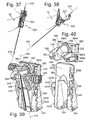
- the barrel member is able to pivot with respect to the body member about the axis of the aligned holes to enable the barrel to assume any desired angular position with respect to the body member from 0° (as shown in Figs. 26 and 27 ) to 40° (as shown in Figs. 27 and 38 ).
- the means for effecting the pivoting of the barrel member with respect to the base member is the heretofore identified slide member 248.
- That member forms a portion of the needle holder subassembly 346 and is best seen in Fig. 41 . It is in the form of an elongated cylindrical needle holder or insert 374.
- the insert is molded of any suitable plastic material and is configured to be disposed within the barrel member 346 to directly hold the needle 12 therein.
- the insert 374 is configured to be rotated about the central longitudinal axis 378 of the barrel member between an open position, such as shown in Fig. 41 , and a closed position, such as shown in Figs. 33 and 39 , and vice versa.
- the insert 374 has a slot 376 extending parallel to the central longitudinal axis of the insert from one end of the insert to the other.
- the width of the slot 376 is just slightly larger than the diameter of the particular diameter needle 12 to be used with the needle guide device.
- the inner end of the slot 376 extends parallel to the central longitudinal axis of the insert and is circular in shape to accommodate the needle 12 therein.
- the depth of the slot i.e., the distance from the outer surface of the insert (and the inner surface of the barrel member) to the inner end of the slot is just slightly larger than the diameter of the needle.
- the needle when the needle is inserted in the slot 376 a portion of the periphery of the slot at the inner end engages the needle, while a portion of the inner surface of the barrel member contiguous with the slot engages another portion of the periphery of the needle, thereby holding the needle in place along a path whose longitudinal axis 378 is parallel to but slightly laterally offset from the central longitudinal axis of the needle holder. That path establishes the trajectory for the needle.
- the upper or entrance end of the slot 376 is chamfered or tapered to facilitate the axial introduction of the needle therein, i.e., the tapered or chamfered surface directs the distal end of the needle towards the slot when the needle is introduced axially.
- a tab 82 projects radially outward from the top end of the insert to enable the user to rotate the insert 376 about central longitudinal axis of the barrel member within the barrel member between the open and closed positions.
- the upper end of the barrel member has a pair of notches 384 immediately adjacent each side of the slot 366. The ends of the notches establish a pair of stops enabling the insert to be rotated through an angle of 180 degrees and no more.
- the tab 382 is grasped by the user to rotate the needle holder 180° about central longitudinal axis 378 (which is also the longitudinal central axis of the barrel member) from the closed position shown in Figs. 31 and 39 to a position like shown in Fig. 41 where the slots 376 and 366 are aligned, whereupon the needle can be inserted laterally through the aligned slots.
- the tab 382 can be rotated 180° back to the closed position shown in Figs. 6 and 14 , thereby holding the needle in place.
- the imaging transducer 10 and needle guide device 20 can be freed (removed) from the needle leaving the needle 12 in place by merely rotating the insert 374 to its open position, whereupon the imaging transducer 10 and needle guide device 320 mounted thereon can be moved as a unit laterally with respect to the needle 12 so that the needle passes through the aligned slots 376 and 366.
- the slide member basically comprises a generally planar body section 386 having a pair of side flanges 388 projecting backward from respective side edges of the body section 386.
- Each flange 388 includes a longitudinally extending slot or channel 388A ( Fig. 31 ) for receipt of a respective side edge 350A or 350B of the base member 304 to slidably mount the slide member on the base member.
- the central portion of the body section 386 includes a recess or cavity 390 to accommodate the barrel member 346 when it is in its 0° orientation, i.e., when the slot 376 of the needle holder mounted within the barrel member extends parallel to the plane of the undercut slot 302 of the base member 304.
- a pair of ears 392 project outward perpendicularly from the lower portion of the body section 386 on each side of the slot 390. Each ear terminates in a free end from which a pivot pin 394 projects.
- the pivot pins 394 are axially aligned and each is configured to be disposed within a respective one of the angularly extending tracks 370 of the barrel member.
- the pivot pins 394 of the slide member When the slide member 348 is its upper-most position with respect to the base member 304, the pivot pins 394 of the slide member will be at the upper ends of the tracks 370 of the barrel member, whereupon the barrel member will be pivoted about its pivot pins 372 to the 0° angular orientation shown in Figs. 26 and 37 . Conversely, when the slide member 348 is its lower-most position with respect to the base member 304, the pivot pins 394 of the slide member will be at the lower ends of the tracks 370 of the barrel member, whereupon the barrel member will be pivoted about its pivot pins 372 to the 40° angular orientation shown in Fig. 27 and 38 .
- the exemplary embodiment of the variable angle needle guide device 320 shown herein includes a locking mechanism to hold the barrel member in any one of a number, e.g., five, discrete distinct predetermined angular orientations with respect to the base member, so that the slide member can be readily and repeatedly slid to any one of those positions and to be held against accidental displacement therefrom.
- the locking mechanism basically comprises a plurality of notches 396 ( Figs. 39 and 40 ) and a slide lock 398.
- the notches 396 extend along the side 350B of the base member 304 at various predetermined spaced locations therealong. Each notch is configured to be engaged by the slide lock 398 to hold the slide member at the position established by the selected notch.
- the slide lock is slidably mounted on the slide member via a flanged rail 330 ( Figs. 40 and 41 ) extending along the ear 392 adjacent the right side of the slide member.
- the flanged rail is configured for slidable receipt in the slide lock.
- the slide lock is best seen in Figs. 41 and 42 and basically comprises a member having a somewhat hollow body including a T-shaped slot 398A in the bottom portion thereof and a L-shaped flange 398B projecting outward from the inner end of the slide lock.
- the T-shaped slot is arranged to receive the flanged rail 330 ( Fig.
- a slot 386A is located adjacent the flanged rail 330 and extends through the channel 388A. When the slide lock is in the extended or locked position the upper section of the L-shaped flange 398B will extend through the slot 386A for disposition in any one of the notches 396 to thereby hold the slide member 348 in place with respect to the body member 304.
- the slide lock incudes a detent mechanism to ensure that the slide lock does not become disconnected from the flanged rail when it is in the retracted position.
- the device 320 includes indicia to provide an indication of the angle to which the needle guide has been set.
- the needle guide includes a plurality of letters, in this exemplary case the letters A through E, located on the front surface of the base member 304.
- the notches associated with the letters A - E establish the angles of 40°, 28°, 18°, 9°, and 3°, respectively.
- the indicia may be in the form of numerical indicia directly identifying the angle, e.g., indicia stating "28°", or numerical indicia representing a particular angle.
- the indicia may be in the form of different colors representing different angles or some other indicia representing different angles.
- the body section 386 includes a window 332 ( Figs. 39 - 41 ) which is configured to expose the particular indicia, e.g., in this example the letters A - E, associated with the notches 396 in which slide lock's L-shaped flange is located.
- the user of the device can press on the top surface of the slide lock to slide it to the retracted or unlocked position to free it from the base member so that the slide member can be slid with respect to the base member until the window 332 exposes the letter (or other indicia) associated with the desired angle for the needle.
- the slide lock can then be slid back to the extended or locked position, whereupon the upper section of the L-shaped flange 398B enters the associated notch 396, thereby releasably locking the slide member in that desired position.
- the needle guide device 320 can be used to establish an angular orientation for the needle that is different than the predetermined angles established by the notches 396, since the construction of the slide member is such that it is continuously slidable with respect to the base member to any position between discrete positions established by those notches. In such a case, all that the user has to do is slide the slide member to the desired position along the base member to establish a desired angle for the needle while keeping the slide lock 398 in its retracted or unlocked position.
- the needle guide device 320 can be used to guide needles or other elongated instruments within the center elevation plane of the transducer allowing free angle movement in relation to the center azimuth plane of the transducer by leaving the slide lock in the unlocked position.
- the needle guide 320 is configured to be directly mounted on an imaging transducer 10 which has been specially constructed or modified to include the heretofore described locating feature (e.g., the coupling member 316).
- the needle guide devices of this invention are also suitable for use on conventional imaging transducers, i.e., imaging transducers without the locating feature or coupling member.
- the heretofore mentioned adaptor bracket 400 constituting another aspect of this invention.
- the adaptor bracket 400 is best seen in Figs. 43 and 44 and enables a needle guide device of this invention to be indirectly mounted on any prior art imaging transducer.
- the adaptor bracket 400 basically comprises a hollow housing 402 made of any suitable material, e.g., a plastic.
- the housing is hollow shaped to accommodate the lower portion of whatever prior art imaging transducer it is to be used on.
- the housing 402 includes a front portion 404 ( Fig. 43 ) and a rear portion 406 ( Fig. 44 ) disposed opposite to the front portion.
- the bottom of the housing is open at 408 to expose the working end of a conventional imaging transducer 10.
- the housing is split to enable it to be opened like a clamshell.
- the housing 402 includes a vertically oriented channel 410 extending from the top edge of the housing at the back portion to approximately the mid-height of the housing.
- the portion of the housing between the bottom of the channel 410 and the bottom edge of the housing forms the "hinge" of the clamshell arrangement.
- the front portion 404 of the housing is split in half from its top edge to its bottom edge by means of a top channel 412A and a contiguous bottom channel 412B.
- the top channel is aligned with and merges with the bottom channel and is slightly wider than the bottom channel.
- the front portion 404 of the housing 402 includes a locating feature of coupling member like that described previously.
- the coupling member of the adaptor bracket 410 is constructed like the coupling member 316 described heretofore, except that it is split by the lower channel 412B into two halves, i.e., a left half and a right half.
- the coupling member 316 includes one half on one side of the channel 412B and the other half on the other side of that channel. Taken together the two half sections of the coupling member 316 form of a projection of the same shape as described earlier with respect to the coupling member forming a part of the transducer housing.
- the mounting of the adaptor bracket 400 on a conventional transducer 10 can be readily accomplished by grasping portions of the front portion 404 of the housing 402 on opposite sides of the channels 412A and 412B to open those channels, whereupon the two portions of the housing 402 on opposite sides of the channel can pivot open like the opening of a clamshell so that the bottom portion of the conventional imaging transducer 10 can be placed between the two open halves of the housing, with the working end of the imaging transducer within the open bottom of the housing.
- the housing can then be released so that it snaps back into its normally closed state on the imaging transducer like shown in Fig. 43 .
- a cover (not shown) can then be placed over the adaptor bracket and the transducer.
- a needle guide device constructed in accordance with this invention can then be releasably mounted on the coupling member as described above.
- any existing prior art imaging transducer can be readily retrofit by means of the adaptor 400 to accommodate the needle guide device 320 (or any other needle guide device in accordance with this invention).
- the structure of the needle guide devices, the coupling members and the adaptor brackets within the scope of this invention.
- the slidable connection between the coupling member of the imaging transducer or the adaptor bracket and the lockable mounting member can be reversed from the exemplary embodiment described above.
- the slide lock member 310 of the needle guide device having a projection which is configured to be received within a recess in the left side of the coupling member of the imaging transducer or the adaptor bracket
- the slide lock can make use of a recess, e.g., an undercut recess, while the left side of coupling member can make use of a projection for slidable receipt in the recess of the slide lock.
- the projection or stop 306 can be in the form of a recess at its free end, while the right side of coupling member includes a projection for receipt in the stop 306, so long as the coupling member is tightly sandwiched between opposing surfaces to releasably secure the needle guide device onto the coupling member.
- the pivotable connection between the slide member and the barrel member can be reversed from the exemplary embodiment described above, i.e., the adjustable angle needle guide can make use of a barrel having at least one projecting fingers and a slide member having an ear with at least one angularly extending track or slot for receipt of the at least one finger.
- the pivotable connection between the slide member and the body member can be reversed from the exemplary embodiment described above, i.e., the barrel member can include a pair of aligned holes and the body member can include a pair of pins for receipt in the aligned holes to enable the barrel member to pivot thereabout.
- the common locating feature e.g., the coupling member
- the common locating feature can be applied to most general purpose ultrasound transducers. That common locating feature can be easily cleaned. Moreover, it is shaped similar to a #1 array indicator, so users of the invention should feel familiar with it. Moreover, the structure and arrangement of the common locating feature causes minimal interference or discomfort during scanning, yet provides stable support of for the needle guide device. Further still, the locating feature allows attachment without damaging an ultrasound cover, if such is used.
- the needle guide device Insofar as the needle guide device is concerned, it enables one to fix the trajectory angle of the device and also allows for user selection of multiple trajectories.
- the device incorporates functionality where the user can change the needle trajectory angle before or after assembly to a transducer, bracket and/or insertion of the needle therein.
- the needle guide device provides visible indicia in the form of a character/number/identification element for each needle path trajectory, allowing the user to identify the trajectory and manually select the corresponding guidelines overlay on the ultrasound system.
- the needle guide devices enable the establishment of an angular range of at least 40° and can maintain a close proximity to the transducer to achieve a minimal "blind zone".
- the needle guide devices of this invention accept multiple versions of inserts sized for differing needle diameters.
- needle guide devices constructed in accordance with this invention exhibit a form factor that is minimal near the transducer lens so as not to interfere with scanning and has a sufficiently low profile without any fixed features that extend past the needle path.
Abstract
Description
- This application claims priority under 35 U.S.C. §119(e) from
U.S. Provisional Application S.N. 62/078,744, filed on November 12, 2014 U.S. Provisional Application S.N. 62/160,776, filed on May 13, 2015 - Needle Guide Devices For Mounting On Imaging Transducers Or Adaptors On Imaging Transducer, Imaging Transducers For Mounting Needle Guide Devices And Adaptors for Imaging Transducers for Mounting Needle Guide Devices Thereon
- This invention relates generally to needle guides for medical imaging instruments and more particularly to devices for guiding needles into selected locations of a patient relative to a medical instrument imaging sensor.
- Imaging instruments, such as ultrasound probes, have revolutionized the manner in which many important medical procedures are performed. These medical instruments utilize substantially non-invasive imaging techniques to explore and assess the condition of human tissue. As a result of these non-invasive imaging techniques, diagnostic and therapeutic protocols have been developed that allow many highly successful and safe procedures to be performed with a minimum of disturbance to patients. For example, ultrasound probes have become an accepted modality for exploring endocavities, e.g., the human digestive and reproductive tracts, of humans and animals in order to conduct routine examinations, as well as to identify evidence of tumors. In particular, using ultrasound, these tumors can be located and assessed. In conjunction therewith it is frequently desirable and even essential that biopsy samples of the tissue or fluid of a suspected tumor be removed for analysis. To that end, biopsy samples may be taken by carefully directing a hand-held needle, such as a biopsy instrument, catheter, or other thin instrument (hereafter referred to collectively as "needle" or "needles") into the body of a patient in order to remove a tissue sample. It is normally desirable that the needle be guided to a specific position within the body. Unfortunately, hand-held direction of a needle is often inadequate, being both inaccurate and time consuming. Thus, various needle guide devices have been designed for use with ultrasonic probes or other imaging transducers to assist in directing needles during imaging analysis.
- Examples of such devices are found in the following
United States Publications and Patents: 2006/0129046 (Stevens et al. ),2007/0049822 (Bunce et al. ),2012/0165679 (Orome et al. ),Des. 424,693 (Pruter 4,469,106 (Harui ),4,576,175 (Epstein ),4,899,756 (Sonek ),5,052,396 (Wedel et al. ),5,076,279 (Arenson et al. ),5,235,987 (Wolfe ),5,623,931 (Wung et al. ),5,758,650 (Miller et al. ),5,924,992 (Park et al. ),5,941,889 (Cermak ),6,203,499 (Imling et al. ),6,292,614 (Pruter ),6,361,499 (Bates et al. ),6,368,280 (Cermak et al. ),6,379,307 (Filly et al. ),6,485,426 (Sandhu ),6,884,219 (Pruter ),7,022,082 (Sonek ),7,087,024 (Pruter ),7,351,205 (Szczech et al. ),7,452,331 (Pruter ),7,588,541 (Floyd et al. ),7,635,336 (Pruter ),7,691,066 (Kosaku ),7,909,815 (Whitmore, III et al. )7,926,776 (Cermak ),7,959,573 (Furia ),8,073,529 (Cermak et al. ),8,137,281 (Huang et al. ),8,216,149 (Oonuki et al. ),8,401,617 (Whitmore, III et al. ) and8,430,889 (Zeng et al. ). - Some of the needle guides disclosed in the aforementioned patents and some commercially available needle guides are designed to be mounted on an ultrasonic probe or other imaging instrument that is itself enclosed within a sterile cover, such as a film. These covers serve to maintain the ultrasound sensor in a sterile environment, while reducing the likelihood of contamination between patients and also reduce the cost of medical procedures by minimizing sterilization costs.
- Notwithstanding the existence of the many prior art needle guides currently available, a need exists for an improved needle guide that is disposable and can be securely mounted on a transducer with a cover and dismounted therefrom and without breaching or otherwise degrading the transducer's cover's integrity, with both of such actions being accomplished easily with minimal effort. A need also exists for a needle guide making use of a universal releasably securable locking feature to either facilitate its direct releasable attachment to prior art transducers by modifying their housings to include a common or universal transducer locating feature or coupling to which the universal releasably locking feature can be releasably secured or to facilitate the indirect releasable attachment of the needle guide to an unmodified prior art transducer by the use of a specially constructed bracket or adapter including a common or universal transducer locating feature to which the universal releasably locking feature can be releasably secured.
- It is commonly a preference of users of ultrasound transducers on which a needle guide is mounted to be able to select a desired angled trajectory path to enable the user to reach an internal site in the patient's body that can be close to or far away from the transducer. That is typically achieved by using an adjustable angle needle guide or a fixed angle needle guide having a desired needle trajectory angle. When a prior art fixed angle needle guide is selected for the task of shallow needle penetration or a prior art adjustable needle guide is adjusted for a shallow needle penetration, the needle trajectory angle will be at a relatively large acute angle to the centerline of the transducer to bring the needle path close to transducer's image plane. In so doing, prior art needle guides typically have some portion which projects a substantial distance laterally outward from the transducer to establish that trajectory. That projecting portion creates a "blind" spot or zone by hiding or otherwise obscuring a portion of the patient's body from direct viewing by the user. Thus, a need also exists for a needle guide device that can establish a trajectory angle close to the image plane, without any portion of it projecting greatly outward laterally from the transducer to thereby minimize the size of any blind spot that could result. The subject invention also addresses that need.
- Moreover, a need exists for an adjustable needle guide device that: (1) is configured to permit the user to change the trajectory angle trajectory of the needle after the needle guide has been mounted on the transducer and also to change the trajectory angle of the needle while the needle is disposed within the needle guide; (2) is configured to enable the user to select desired predetermined needle trajectory angles corresponding to guidelines overlaid on the ultrasound system; (3) permits the user to utilize a "freehand" approach, i.e., to adjust the needle trajectory angle to any desired angle, to maintaining the needle within the ultrasound image plane of the transducer; and (4) is configured to enable the user to change the trajectory angle at any time, e.g., before introduction of the needle into the needle guide device or after the needle has been inserted therein. The subject invention also addresses those needs.
- In accordance with one aspect of this invention there is provided a needle guide device configured for releasable mounting on an imaging transducer or on an adaptor on an imaging transducer. The imaging transducer or the adaptor each includes a coupling member comprising a first portion. The needle guide device comprises a lockable mounting member and a needle guide assembly. The needle guide assembly comprises a body member and a needle holder. The needle holder is mounted on the body member and comprises an elongated passageway for receipt of a needle to establish the trajectory of the needle when the needle is located therein. The lockable mounting member comprises a slidable member having a second portion. One of the first portion and the second portion comprises a projection, and the other of the first portion and the second portion comprises a recess. The slidable member is configured to be slidably coupled to the body member and slidable from an unlocked position to a locked position and vice versa. The projection is configured for receipt in the recess to releasably secure the slidable member to the imaging transducer or the adaptor when the slidable member is in the locked position, thereby releasably mounting the needle guide device on the imaging transducer.
- In accordance with another aspect of this invention the needle holder is adjustably mounted on the body member to enable the needle holder to be oriented to various selected orientations, e.g., from approximately 0° to approximately 40° degrees, with respect to the body member to establish various angled trajectories for the needle.
- In accordance with another aspect of this invention the needle holder is oriented at a predetermined fixed angle with respect to the body member to establish a desired angled trajectory for the needle.
- In accordance with another aspect of this invention, the slidable member comprises a portion of a lockable mounting assembly. The lockable mounting assembly comprises a body member including a stop. The stop is configured to engage the slidable member when the slidable member is in the locked position, whereupon the coupling member is held between the stop and the second portion of the slidable member.
- In accordance with another aspect of this invention a needle guide device configured for mounting on an imaging transducer or on an adaptor on an imaging transducer is provided. The needle guide device comprises a base member, a barrel member, a slide member and a needle holder. The needle holder is mounted on the barrel member and comprises an elongated passageway for receipt of a needle to establish the trajectory of the needle when the needle is located therein. The barrel member is pivotably mounted on the base member. The slide member is slidable with respect to the base member and coupled to the barrel member to pivot the barrel member with respect to the base member to a first angular orientation when the slide member is slid to a first position, and to pivot the barrel portion with respect to the base member to a second angular orientation when the slide member is slid to a second position. The needle holder establishes a first angular trajectory for the needle when the barrel member is in the first angular orientation and establishes a second angular trajectory for the needle when the barrel member is in the second angular orientation. The second angular trajectory is different than the first angular trajectory.
- In accordance with another aspect of this invention the needle guide assembly comprises a base member, a needle holder subassembly and a slide member. The needle holder subassembly comprises a barrel member and the needle holder. The needle holder is located in the barrel member and comprises an elongated passageway for receipt of a needle to establish the trajectory of the needle when the needle is located therein. The barrel member is pivotably mounted on the base member. The slide member is slidable with respect to the base member and coupled to the barrel member to pivot the barrel member with respect to the base member to a first angular orientation when the slide member is slid to a first position, and to pivot the barrel portion with respect to the base member to a second angular orientation when the slide member is slid to a second position. The needle holder establishes a first angular trajectory for the needle when the barrel member is in the first angular orientation and establishes a second angular trajectory for the needle when the barrel member is in the second angular orientation. The second angular trajectory is different than the first angular trajectory.
- In accordance with another aspect of this invention the barrel member comprises a cylindrical cavity having a central longitudinal axis and wherein the needle holder comprises an elongated cylindrical member located within the cylindrical cavity and rotatable about the central longitudinal axis. The needle holder has a passageway extending therethrough parallel to the central longitudinal axis. The passageway is configured for receipt of the needle therein to establish the needle's trajectory. The barrel portion includes a slot in communication with the cylindrical cavity and extending parallel and to the central longitudinal axis. The needle holder comprises a slot in communication with the passageway. The needle holder is rotatable within the cylindrical cavity between a closed and open position, and vice versa. The slot in the needle holder is aligned with the slot in the barrel when the needle holder is rotated to the open position. When in the open position a needle extending through the passageway can be removed from the needle holder laterally through the aligned slots and a needle can be introduced into the passageway laterally through the aligned slots. The slots are unaligned when the needle holder is in the closed position, whereupon a needle disposed in the passageway is held therein.
- In accordance another aspect of this invention the barrel member comprises a cylindrical cavity having a central longitudinal axis and wherein the needle holder comprises an elongated cylindrical member located within the cylindrical cavity and rotatable about the central longitudinal axis. The needle holder has a passageway extending therethrough parallel to the central longitudinal axis. The passageway is configured for receipt of the needle therein to establish the needle's trajectory. The barrel portion includes a slot in communication with the cylindrical cavity and extending parallel and to the central longitudinal axis. The needle holder comprises a slot in communication with the passageway. The needle holder is rotatable within the cylindrical cavity between a closed and open position, and vice versa. The slot in the needle holder is aligned with the slot in the barrel when the needle holder is rotated to the open position. When in the open position a needle extending through the passageway can be removed from the needle holder laterally through the aligned slots and a needle can be introduced into the passageway laterally through the aligned slots. The slots are unaligned when the needle holder is in the closed position, whereupon a needle disposed in the passageway is held therein.
- In accordance with another aspect of this invention there is provided an imaging transducer for providing a signal representing an image of an internal portion of the body of a patient for visualization by a user of the imaging transducer. The imaging transducer has a housing comprising a coupling member for enabling the releasable securement of a needle guide device thereto. The needle guide device comprises a lockable mounting member having a second portion. The coupling member comprises a first portion. One of the first portion and the second portion comprises a projection, and the other of the first portion and the second portion comprises a recess. The lockable mounting member is slidable from an unlocked position to a locked position with respect to the needle guide device, and vice versa. The projection is configured for receipt in the recess to releasably secure the lockable mounting member to the coupling member when the lockable mounting member is in the locked position, thereby releasably mounting the needle guide device on the imaging transducer.
- In accordance with another aspect of this invention there is provided an adaptor for mounting on an imaging transducer. The imaging transducer is configured for providing a signal representing an image of an internal portion of the body of a patient for visualization by a user of the imaging transducer. The adaptor has a housing comprising a coupling member for enabling the releasable securement of a needle guide device thereto. The needle guide device comprises a lockable mounting member. The lockable mounting member has a second portion. The coupling member comprises a first portion. One of the first portion and the second portion comprises a projection, and the other of the first portion and the second portion comprises a recess. The lockable mounting member is slidable from an unlocked position to a locked position with respect to the needle guide device, and vice versa. The projection is configured for receipt in the recess to releasably secure the lockable mounting member to the coupling member when the lockable mounting member is in the locked position, thereby releasably mounting the needle guide device on the adaptor.
-
-
Fig.1 is an isometric view of one exemplary embodiment of a needle guide device constructed in accordance with this invention shown mounted on an imaging transducer, e.g., an ultrasound probe, with a conventional cover interposed therebetween, and with the needle guide device being configured to provide a needle trajectory angle that can be varied as desired; -
Fig. 2 is an enlarged isometric view of the needle guide device shown inFig. 1 , but without the needle shown therein; -
Fig. 3 is an isometric view of the bottom portion of the imaging transducer ofFig. 1 showing a coupling member serving as a locating feature for releasably mounting the needle guide on the transducer; -
Fig. 4 is a top plan view of the coupling member of the imaging transducer shown inFig. 3 ; -
Fig. 5 is an enlarged isometric view of a lockable mounting member forming a portion of the needle guide device ofFigs. 1 and 2 shown adjacent the coupling member of the imaging transducer, to enable the lockable mounting member to be releasably secured thereto to releasably mount the needle guide device on the transducer; -
Fig. 6 is an isometric view of the lockable mounting member shown inFig. 5 ; -
Fig. 7 is an isometric view of the lockable mounting member ofFig. 5 , but taken from a different direction; -
Fig. 8 is a reduced side elevation view of the needle guide device ofFig. 1 shown on the transducer establishing a 0° angle trajectory for the needle; -
Fig. 9 is a side elevation view, similar to that ofFig. 8 , but showing the needle guide device ofFig. 1 establishing a 40° angle trajectory for the needle; -
Fig. 10 is an exploded isometric view of the needle guide assembly shown inFig. 2 taken from a front oblique angle; -
Fig. 11 is an exploded isometric view of the needle guide assembly shown inFig. 2 taken from a rear oblique angle; -
Fig. 12 is an isometric view of the needle guide device, like that shown inFig. 2 , but with a component thereof in an open position to enable a needle to be inserted laterally into the needle guide device or removed laterally from the needle guide device; -
Fig. 13 is an isometric view of the needle guide device ofFig. 1 and 2 shown mounted on an adaptor bracket constructed in accordance with one aspect of this invention, with the adaptor bracket being mounted on a conventional imaging transducer, e.g., an ultrasound probe, with a conventional cover interposed therebetween (although not shown in this figure); -
Fig. 14 is an isometric view of the adaptor bracket ofFig. 13 shown mounted on a conventional imaging transducer; -
Fig. 15 is an enlarged isometric view of the bottom portion of the adaptor bracket ofFig. 14 showing a coupling member thereof which serves as a locating feature for releasably mounting the needle guide device on the adaptor bracket and hence on the conventional imaging transducer; -
Fig. 16 is a top elevation view of the portion of the coupling member of the adaptor bracket shown inFigs. 14 and 15 ; -
Fig. 17 is a reduced isometric view of the adaptor bracket ofFig. 14 but showing the opposite side thereof, i.e., the side opposite the coupling member; -
Fig. 18 is an isometric view of another exemplary embodiment of a needle guide device constructed in accordance with this invention shown mounted on an imaging transducer, e.g., an ultrasound probe, with a conventional cover interposed therebetween, and with the needle guide device being configured to provide a fixed predetermined needle trajectory angle; -
Fig. 19 is a side elevation view of the needle guide shown inFig. 18 ; -
Fig. 20 is a reduced side elevation view of the needle guide device ofFig. 18 shown on the transducer establishing a 0° angle trajectory for the needle; -
Fig. 21 is a side elevation view, similar to that ofFig. 20 , but showing the needle guide device ofFig. 18 establishing a 40° angle trajectory for the needle; -
Fig. 22 is an exploded isometric view of the needle guide assembly shown inFig. 18 taken from a front oblique angle; -
Fig. 23 is an exploded isometric view of the needle guide assembly shown inFig. 18 taken from the rear side thereof; -
Fig. 24 is an isometric view of the needle guide device ofFig. 18 , but with a component thereof in an open position to enable a needle to be inserted laterally into the needle guide device or removed laterally from the needle guide device; -
Fig. 25 is an isometric view of an adaptor bracket constructed in accordance with this invention shown mounted on a conventional transducer, e.g., an ultrasound probe, to enable a needle guide device like shown inFig. 18 to be mounted thereon; -
Fig. 26 is an isometric view of one exemplary embodiment of a needle guide device constructed in accordance with this invention shown mounted on an imaging transducer, e.g., an ultrasound probe, and with the needle guide device being configured to provide a needle trajectory angle that can be varied as desired, but which as shown has been adjusted to establish a 3° angle of penetration the needle; -
Fig. 27 is an isometric view similar toFig. 26 , but showing the needle guide device adjusted to establish a 40° angle of penetration for the needle; -
Fig. 28 is a slightly enlarged isometric view of the bottom portion of the imaging transducer ofFig. 26 showing a coupling member serving as a locating feature for releasably mounting the needle guide device on the transducer; -
Fig. 29 is a top plan view of the coupling member of the imaging transducer taken along line 29-29 ofFig. 28 ; -
Fig. 30 is a front elevation view of the coupling member shown inFigs. 28 and 29 ; -
Fig. 31 is an enlarged front oblique isometric view showing the needle guide device ofFig. 26 about to be mounted on the imaging transducer via the coupling member shown inFigs. 28-30 ; -
Fig. 32 is an front oblique isometric view of a portion of the needle guide device ofFig. 31 for releasable securement to the coupling member shown inFigs. 26-28 to releasably mount the needle guide device onto the imaging transducer; -
Fig. 33 is a rear oblique isometric view of the portion of the needle guide device shown inFig. 32 ; -
Fig. 34 is an enlarged exploded isometric view showing a portion of a lockable mounting assembly forming a portion of the needle guide device ofFig. 26 ; -
Fig. 35 is an isometric view similar toFig. 34 but showing the lockable mounting member of the lockable mounting assembly disposed within a corresponding slot in the body member of the needle guide device; -
Fig. 36A is a slightly enlarged elevation view of the locking lever forming a portion of the lockable mounting assembly shown inFig. 34 ; -
Fig. 36B is an isometric view of the locking lever shown inFig. 36A ; -
Fig. 37 is a reduced side elevation view of the needle guide device shown inFig. 26 ; -
Fig. 38 is a reduced side elevation view of the needle guide device shown inFig. 27 ; -
Fig. 39 is an enlarged front oblique isometric view of the needle guide device shown inFig. 31 but taken from a different angle to more clearly show the mechanism for adjusting the angle of penetration for a needle located within the needle guide device; -
Fig. 40 is an exploded isometric view showing a portion of the mechanism for adjusting the angle of penetration for a needle located within the needle guide device; -
Fig. 41 is an exploded isometric view of the needle guide device ofFig. 26 , but without the lockable mounting assembly; -
Fig. 42 is an enlarged isometric view of a lock slide or lever forming a portion of the mechanism for adjusting the angle of penetration of a needle located within the needle guide device; -
Fig. 43 is a reduced isometric view of an adaptor constructed in accordance with one aspect of this invention shown mounted on a conventional imaging transducer to enable a needle guide device constructed in accordance with this invention to be able to be mounted thereon, and hence mounted on a conventional imaging transducer; and -
Fig. 44 is an isometric view similar toFig. 43 , but showing the opposite side of the adaptor, i.e., the side opposite the coupling member, mounted on the conventional imaging transducer shown inFig. 43 . - Referring now to the various figures of the drawing wherein like reference characters refer to like parts, there is shown in
Fig. 1 one exemplary preferred embodiment of a reusableneedle guide device 20 constructed in accordance with this invention. Another preferred exemplary embodiment of a reusable needle guide device 20' constructed in accordance with this invention is shown inFig. 18 . Still another reusableneedle guide device 20" constructed in accordance with this invention is shown inFig. 21 . Those three exemplary embodiments are configured to be releasably mounted directly on an imaging instrument, e.g., an ultrasound transducer orprobe 10, or indirectly mounted on anadaptor bracket 200 constructed in accordance with this invention and shown inFigs. 13 and25 , to guide aneedle 12 or any other elongated instrument through a desired path or trajectory into the body of a patient (human or animal) for a tissue biopsy procedure or any number of other medical procedures. - As will be seen and described in detail later the
needle guide device 20 is adjustable, so that it can establish a trajectory path enabling the needle or instrument to reach an internal site in the patient's body that is close to or far away from the distal or working end of the transducer. In particular, theneedle guide device 20 is configured to enable the user to adjust the needle angle trajectory through a wide range, e.g., a range of approximately 40 degrees. The needle guide device 20' ofFig. 18 and theneedle guide device 20" ofFig. 21 are not adjustable. Rather, each establishes a fixed, different respective, trajectory angle for the needle or other instrument. In accordance with one preferred aspect of this invention a plurality of fixed angle needle guide devices, likeguides 20' and 20" can be provided in the form of a kit of several fixed needle guide devices, each establishing its own, and different, angled trajectory path. Thus, by the appropriate selection of the fixed angle needle guide the user can establish the desired angular path for the needle or other instrument. - Irrespective of whether the needle guide device is an adjustable angle or fixed angle device, all of the needle guide devices of this invention make use of a mounting feature to enable them to be readily and quickly mounted on an
imaging transducer 10, with aconventional cover 14 interposed therebetween. That cover is typically formed of a thin, flexible sheath of any suitable material, e.g., latex, into a suitable shape, e.g., condom-shaped sheath, to be placed over the imaging transducer before the needle guide device is mounted thereon to keep the transducer sanitary. In the interest of drawing simplicity the cover has been omitted from many of the figures of the drawing, it being understood that the cover is, in fact, interposed between the needle guide device and the imaging transducer on which the needle guide device is mounted or interposed between the needle guide device and the adaptor bracket on which the needle guide is mounted. - The releasably mounting feature of this invention will be described in detail later. Suffice it for now to state that the exemplary
needle guide devices needle guide device 20 and the fixedneedle guide device 20" (and all other needle guides constructed in accordance with subject invention), enable the user to establish a very shallow depth of penetration for a needle, with a minimal blind spot, since the needle guides do not include any portion which projects far out from the transducer to block the view of the user, i.e., all of the needle guide devices of this invention have a compact form factor. - Turning now to
Figs. 1 and 2 it can be seen that theneedle guide device 20 basically comprises aneedle guide assembly 22 and a lockable mountingmember 24. The lockable mounting member is configured to be releasably secured to a universal or common locating feature or couplingmember 16 that is located on the housing of the transducer adjacent the distal or working end of the transducer. Thecoupling member 16 is preferably mounted at the location of the typical "#1 array indicator" of a conventional ultrasonic transducer. As best seen inFigs. 3 - 5 thecoupling member 16 is in the form of a projection of somewhat rectangular profile and having an enlargedtop portion 16A and a pair of undercutrecesses 16B on the opposed long sides of the projection. - The
lockable mounting member 24 is best seen inFigs. 6 and 7 and basically comprises a rectangularly shaped frame, e.g., an integrally molded plastic component, having one side section in the form of a thickenedhandle 26, a pair ofintermediate sections opposite side section 32 connected between the intermediate sections. Across-piece section 34 extends parallel and closely adjacent the handle section. The cross piece includes a projection, e.g., a flange, 36 extending along the length thereof. As best seen inFig. 6 , thesections window 38 therebetween. Thewindow 38 is configured to receive the transducer'scoupling member 16 and the portion of thecover 14 overlying the top16A of the coupling member when theguide device 20 is to be mounted on the transducer. In particular, as will be described in detail later, thelockable mounting member 24 is configured to be slidably received within a slot or channel 62 (to be described later) forming a portion of theneedle guide assembly 22 so that it can be slid by a user pushing on the handle from an open position wherein the coupling member is located within thewindow 38, to a locked position, and vice versa. When the lockable mounting member is in the locked position the coupling member is still located within thewindow 38, but theflanged projection 36 is disposed within the confronting undercutrecess 16B of thecoupling member 16. This action releasable secures thelockable mounting member 24 to the transducer coupling member. - In order to ensure that the lockable mounting member is held in the locked position so that it is resistant to accidental displacement, it includes a pair of extending
fingers 40 projecting outward from the respective ends of itsside section 32. Eachfinger 40 is connected to its respective end of theside section 32 by a shortflexible bridge section 42, which engages a respective portion in the slot orchannel 62 of the needle guide assembly to securely hold the lockable mounting member in the locked position. Thebridge sections 42, being resilient, are effectively spring-biased so that they are configured to be flexed inward when thefingers 40 are squeezed together by a user. This brings thebridge sections 42 towards each other to thereby release thelockable mounting member 24 from its locked position. That action enables the lockable mounting member to be slid to its open position, wherein theflanged projection 36 is outside of (beyond) the undercutrecess 16B of the coupling member and with the coupling member being within thewindow 38 to effectively free the coupling member, thereby disconnecting the needle guide device from the imaging transducer. If desired, the lockable mounting member can be removed from the needle guide by squeezing thefingers 40 together after the transducer'scoupling member 16 is out of thewindow 38 and then pulling on thehandle 36 to pull the lockable mounting member out of the slot orchannel 62. - Referring now to
Figs. 2 ,10 and11 the details of theneedle guide assembly 22 will now be described. To that end, it basically comprises a body orbase member 44, aneedle holder subassembly 46 and a slide member 48. Each is molded of a suitable plastic material. Thebody member 44 comprises a generally flat panel having a pair oflong sides flanged ears sides circular hole 54 for accommodating a respective pivot pin of a cylindrically shaped barrel member 56 (to be described shortly) forming a portion of theneedle holder subassembly 46. Theholes 54 are axially aligned. A generallyplanar back wall 58 extends between the marginal edges of the triangular ears as best seen inFig. 9 . The front portion of thebody member 44 includes an arcuate recess orcavity 60, as best seen inFig.8 , which is configured to accommodate thebarrel member 56. Theback wall 58 includes a slot orchannel 62 extending from one side of the back wall to the other and is open to the back surface of the back wall from theear 52A to a point adjacent theear 52B. Acentral opening 64 is located in the front surface of the back wall and is shaped to accommodate thetop portion 16A of thetransducer coupling member 16 to releasably secure the needle guide device to the transducer. - The
barrel member 56 is an elongated generally tubular member having a centrally locatedfront slot 66 extending parallel to the centrallongitudinal axis 78 of the barrel member. A pair oftriangular ears 68 project outward from thebarrel member 56 on opposite sides of theslot 66. Each ear includes a linear slot or track 70 (only one of which can be seen in the figures) which extends at an acute angle, e.g., 15°, from the longitudinal axis of the barrel member, and oriented upward and outward as shown inFigs. 2 and 8 - 12 . The bottom edge portion of the barrel member includes a pair of pivot pins 72 projecting outward therefrom. Thepins 72 are diametrically opposed and axially aligned, and each pin is configured to be disposed within arespective hole 54 in thebody member 44. When so located the barrel member is able to pivot with respect to the body member about the axis of the aligned holes and pins to enable the barrel to assume any desired angular position with respect to the body member from 0° (as shown inFig. 8) to 40 ° (as shown inFig. 9 ). The means for effecting the pivoting of the barrel member with respect to the base member is the heretofore identified slide member 48. - Before describing the slide member, a description of the member for holding the
needle 12 in theneedle guide device 20 is in order. That member is best seen inFigs. 10 and11 . It is in the form of an elongated cylindrical needle holder orinsert 74. The insert is molded of any suitable plastic material and is configured to be disposed within thebarrel member 46 to directly hold theneedle 12 therein. Moreover, as will be seen and described later, theinsert 74 is configured to be rotated about thecentral axis 78 of the barrel member between an open position, such as shown inFig. 12 , and a closed position, such as shown inFig. 2 , and vice versa. Theinsert 74 has aslot 76 extending parallel to the centrallongitudinal axis 78 of the insert from one end of the insert to the other. The width of theslot 76 is just slightly larger than the diameter of theparticular diameter needle 12 to be used with the needle guide device. The inner end 80 of theslot 76 extends parallel to the centrallongitudinal axis 78 and is circular in shape to accommodate theneedle 12 therein. The depth of the slot, i.e., the distance from the outer surface of the insert (and the inner surface of the barrel member) to the inner end of the slot is just slightly larger than the diameter of the needle. Thus, when the needle is inserted in the slot 76 a portion of the periphery of the slot at the inner end 80 engages the needle, while a portion of the inner surface of the barrel member contiguous with the slot engages another portion of the periphery of the needle, thereby holding the needle in place along a path that is parallel to the longitudinalcentral axis 78 of the needle holder. That path establishes the trajectory for the needle. - It should be pointed out at this juncture that different inserts with
different size slots 76 can be provided in lieu of theinsert 76 shown herein to accommodate different diameter needles. - As best seen in
Fig. 11 the upper or entrance end of theslot 76 is chamfered or tapered to facilitate the axial introduction of the needle therein, i.e., the tapered or chamfered surface directs the distal end of the needle towards the slot when the needle is introduced axially. - A
tab 82 projects radially outward from the top end of the insert to enable the user to rotate theinsert 76 about centrallongitudinal axis 78 within the barrel member between the open and closed positions. In order to accommodate thetab 82 the upper end of the barrel member has a pair ofnotches 84 immediately adjacent each side of theslot 66. The ends of the notches establish a pair of stops enabling the insert to be rotated through an angle of 180 degrees and no more. - When the needle holder or insert 74 is in the open position, like that shown in
Fig. 12 , theneedle 12 can be inserted laterally therein, instead of axially through the chamfered upper end of the insert as discussed above. To that end, thetab 82 is grasped by the user to rotate theinsert 74 180° about central longitudinal axis 78 (which is also the longitudinal central axis of the barrel member) from the position shown inFigs. 1 and 2 to the position like shown inFig. 12 . At that time theslot 76 of the insert will be aligned with theslot 66 of the barrel member, whereupon the needle can be inserted laterally through the aligned slots. Once the needle is in theslot 76 and parallel to the longitudinalcentral axis 78, thetab 82 can be rotated 180° back to the closed position shown inFigs. 1 and 2 , thereby holding the needle in place. - As will be appreciated by one skilled in the art, after the needle has been deployed, i.e., inserted into the patient's body along the desired trajectory, the
imaging transducer 10 andneedle guide device 20 can be freed (removed) from the needle leaving theneedle 12 in place by merely rotating theinsert 74 to its open position, like shown inFig. 12 , whereupon theimaging transducer 10 andneedle guide device 20 mounted thereon can be moved as a unit laterally with respect to theneedle 12 so that the needle passes through the alignedslots 66 and 77. - Turning now to
Figs. 10 and11 the details of the construction and operation of the slide member 48 will be described. The slide member basically comprises a generallyplanar body section 86 having a thickened pair ofside flanges 88, each of which includes a longitudinally extending slot or channel for receipt of arespective side edge base member 44 to slidably mount the slide member thereon. The central portion of the body section includes a recess orcavity 90 to accommodate thebarrel member 46 when it is in its 0° orientation, i.e., when theslot 76 of the needle holder mounted within the barrel member extends parallel to the plane of theslot 62 of the base member. That orientation is shown inFigs. 1 and8 . A pair ofears 92 project outward perpendicularly from the bottom of thebody section 86 on each side of theslot 90. Each ear terminates in a free end from which apivot pin 94 projects. The pivot pins 94 are axially aligned and each is configured to be disposed within a respective one of theangularly extending tracks 70 of the barrel member. - When the slide member 48 is its upper-most position with respect to the
base member 46, the pivot pins 94 of the slide member will be at the upper ends of thetracks 70 of the barrel member, whereupon the barrel member will be pivoted about its pivot pins 70 to the 0° angular orientation shown inFig. 8 . Conversely, when the slide member 48 is its lower-most position with respect to thebase member 46, the pivot pins 94 of the slide member will be at the lower ends of thetracks 70 of the barrel member, whereupon the barrel member will be pivoted about its pivot pins 70 to the 40° angular orientation shown inFig. 9 . - The exemplary embodiment of the variable angle
needle guide device 20 shown herein includes a detent mechanism to hold the barrel member in any one of a number, e.g., seven, discrete distinct predetermined angular orientations with respect to the base member, so that the slide member can be readily and repeatedly slid to any one of those positions and to be held therein against accidental displacement therefrom. The detent mechanism basically comprises a plurality of pairs of notches 96 (Figs. 10 and11 ) extending along thesides pivotable arms 98 mounted on theside flanges 88. The upper end of eacharm 98 is in the form of a handle and a lower portion in the form of an inwardly directedfree end finger 100. Each arm is mounted on a respective one of the side flanges by aflexible bridge section 102, whereupon when thehandles 98 are squeezed together theflexible bridge sections 102 flex to cause the twoopposed fingers 100 to move apart from each other. That action frees the pair offingers 100 from whatever pair ofnotches 96 they had been located in so that the slide member 48 can then be slid to any other position with respect to thebase member 44, whereupon the pair of fingers are aligned with the pair of notches at that new position. Thehandles 98 can then be released, causing them to snap back to bring the fingers into those notches to releasably secure the slide in that position. - In order to facilitate usage of the
needle guide device 20 to establish a desired angular trajectory for the needle, thedevice 20 includes indicia to provide an indication of the angle to which the needle guide has been set. In particular, the needle guide includes a plurality of letters, in this exemplary case the letters A through G, located on the front surface of thebase member 44. The notches associated with the letters A - G, establish the angles of 45°, 35°, 25°, 20°, 15°, 10°, and 5°, respectively. - It should be pointed out at this juncture that the use of letters to indicate a desired angular orientation for the needle is merely exemplary. Thus, the indicia may be in the form of numerical indicia directly identifying the angle, e.g., indicia stating "40°", or numerical indicia representing a particular angle. Alternatively, the indicia may be in the form of different colors representing different angles or some other indicia representing different angles.
- In any case, the top edge portion of the
body section 86 includes a pair of windows 104 (Fig. 10 ) which are configured to expose the particular indicia, e.g., in this example the letters A - G, associated with the pair ofnotches 96 in which the pair offingers 100 are located. Thus, the user of the device can press on thehandles 98 of the slide member to free its fingers from the base member so that the slide member can be slid with respect to the base member until one ofwindows 104 exposes the letter (or other indicia) associated with the desired angle for the needle. The handles can then be released to enable the arms to spring back, whereupon the fingers enter the associated notches, thereby releasably locking the slide in that desired position. - It should be noted that while the
needle guide device 20 as described above is configured so that the slide can be moved to any of the seven discrete positions established by the pairs ofnotches 96 to establish the angled needle trajectory associated with that pair of notches, the spring bias provided by theflexible bridge sections 102 will hold the free end of the fingers in sufficient frictional engagement with the side edges 50A and 5B of the base member between thenotches 96. Thus, the slide member can be slid and held at a "free hand" position in between any of the notches. This feature is important to enable the user to establish a precise desired needle trajectory angle even if it isn't one of the pre-established angles defined by the pairs of notches. - As discussed above, the
needle guide 20 is configured to be directly mounted on animaging transducer 10 which has been specially constructed or modified to include the heretofore described locating feature (e.g., coupling member 16). The needle guide devices of this invention are also suitable for use on conventional imaging transducers, i.e., imaging transducers without the locating feature or coupling member. To that end, the heretofore mentioned adaptor bracket, constituting another aspect of this invention, is provided. Theadaptor bracket 200 is best seen inFigs. 13 - 17 and enables a needle guide of this invention to be indirectly mounted on the priorart imaging transducer 10. Theadaptor bracket 200 basically comprises ahollow housing 202 made of any suitable material, e.g., a plastic. The housing is hollow and shaped to accommodate the lower portion of whatever prior art imaging transducer it is to be used on. Thehousing 202 includes afront portion 204 and arear portion 206 disposed opposite to the front portion. The bottom of the housing is open to expose the working end of theimaging transducer 10. In order to facilitate the disposition of theadaptor bracket 200 on the bottom portion of the conventional imaging transducer, the housing is split to enable the housing to be opened like a clamshell. In particular thehousing 202 includes a vertically orientedchannel 208 extending from the top edge of the housing at the back portion to approximately the mid-height of the housing. Theportion 210 of thehousing 202 between the bottom of thechannel 208 and the bottom edge of the housing (i.e., the open bottom of the housing) forms the "hinge" of the clamshell arrangement. Thefront portion 204 of the housing is split in half from its top edge to its bottom edge by means of atop channel 212 and abottom channel 214. The top channel merges with the bottom channel and is slightly wider than the top channel. - In order to enable a needle guide device constructed in accordance with this invention on the
adaptor bracket 200, the front portion of thehousing 202 includes acoupling member 216. Thecoupling member 216 is constructed like thecoupling member 16 described heretofore, except that it is split by thechannel 214 into two halves. In particular, thecoupling member 216 includes one half on one side of thechannel 214 and the other half on the other side of that channel. Taken together the two half sections of the coupling member form of a projection of somewhat rectangular profile and having an enlarged top portion 116A and a pair of undercut recesses 116B on the opposed long sides of the projection, i.e., on one side of one half section and on the corresponding side of the other half section. - The mounting of the
adaptor bracket 200 can be readily accomplished by grasping portions of the front portion of the housing on opposite sides of thechannel 212 to open that channel, whereupon the two portions of the housing on opposite sides of the channel can pivot open abouthinge 210 so that the bottom portion of theconventional imaging transducer 10 can be placed between the two open halves of the housing, with the working end of the imaging transducer within the open bottom of the housing. The housing can then be released so that it snaps back into its normally closed state on the imaging transducer like shown inFig. 14 . Acover 14 can then be placed over the adaptor bracket and the transducer. A needle guide device constructed in accordance with this invention can then be releasably mounted on the coupling member as described above with reference to theneedle guide 20. - Thus, any existing prior art imaging transducer can be readily retrofit by means of the
adaptor 200 to accommodate the needle guide device 20 (or any other needle guide device making use of the lockable mounting member). - Turning now to
Figs. 18 - 20 and 22 - 24 the details of the fixed angle needle guide device 20' will now be described. That device makes use of the samelockable mounting member 24 for releasable mounting on thesame coupling member - As best seen in
Figs. 12 - 14 and 16 - 18 , the needle guide device 20' basically comprises aneedle guide assembly 122 and thelockable mounting member 24. Those components are each preferably molded of any suitable plastic material. Theneedle guide assembly 122 basically comprises abase member 126 having a slot orchannel 128 extending through it from one side of the base member to the other side. Thechannel 128 is configured to slidably receive thelockable mounting member 24 in a manner similar to the slot orchannel 62 in the adjustableneedle guide device 20. The back surface of thebase member 126 includes arecess 130. - With the
lockable mounting member 24 in place within the slot orchannel 128 in its open position, thecoupling member 16 of the transducer, with a portion of thecover 14 overlying the top 16A of thecoupling 16, can be extended through therecess 130 and through thewindow 38 in the lockable mounting member. Then thehandle 26 of the lockable mounting member can be pushed inward to move the lockable mounting member to the locked position, whereupon theflanged projection 36 is located within the undercut recess 12B of thecoupling member cover 14 interposed therebetween. - The needle guide assembly also includes a
barrel member 132 and aneedle holder 134. Thebarrel member 132 is an elongated generally tubular member having aslot 136 extending parallel to the centrallongitudinal axis 138 of the barrel member from the top of the barrel member to the bottom thereof. The barrel member is fixedly mounted on thebase member 126 so that the longitudinalcentral axis 138 of the barrel member, which defines the needle trajectory, extends at a predetermined angle to thebase member 126. In the exemplary embodiment 20' shown inFigs. 18 - 20, 22 and 24 the predetermined angle is 5° in relation to its mountingmember 126. In theexemplary embodiment 20" shown inFig. 21 and25 the predetermined angle is 45° in relation to its mountingmember 126. The means for mounting thebarrel member 132 in its particular angular orientation comprises a pair ofarcuate struts 140 projecting outward from thebase member 126. - The
needle holder 134 is in the form of an elongated cylindrical insert that is configured to be disposed within thebarrel member 132 to directly hold theneedle 12 therein. Moreover, the insert is configured to be rotated about the longitudinalcentral axis 138 of the barrel member between an open position, such as shown inFig. 24 , and a closed position, such as shown inFigs. 18 and 20 , and vice versa. The elongated cylindrical insert has aslot 142 extending parallel to the central longitudinal axis of the insert from one end of the insert to the other. The width of theslot 142 is just slightly larger than the diameter of theparticular diameter needle 12 to be used with the needle guide device 20'. The inner end of theslot 142 is circular in shape to accommodate theneedle 12 therein. The depth of the slot, i.e., the distance from the outer surface of the insert 134 (and the inner surface of the barrel member 132) to the inner end of the slot is just slightly greater than the diameter of the needle. Thus, when the needle is inserted in theslot 142 and the insert is in the closed position a portion of the periphery of theslot 142 engages a portion of the periphery of theneedle 12, while a portion of the inner surface of the barrel member contiguous with the slot engages another portion of the periphery of the needle, thereby holding the needle in place along a path that is parallel to the longitudinalcentral axis 138 of the needle holder. That path establishes the trajectory for the needle. - As is the case of the adjustable
needle guide device 20, different inserts or needle holders can be provided withdifferent size slots 142 to accommodate different diameter needles for use with a fixed angle needle guide device, like device 20'. Moreover, like theneedle holder 74 ofdevice 20, the needle holder of device 20' makes use of aslot 142 whose upper end is chamfered to facilitate the axial introduction of the needle therein. - A
tab 144 projects radially outward from the top end of theinsert 132 to enable the user to rotate the insert about centrallongitudinal axis 138 within thebarrel member 134 between the open and closed positions, and vice versa. In order to accommodate thetab 144 the upper end of the barrel member has an internal T-shaped slot having anelongated portion 146 extending about a portion of the periphery of the barrel member just below the top edge thereof and anentry portion 148 extending from the top edge to theelongated portion 146. Thetab 144 includes a narrow section where the tab merges with the tubular insert and which is configured to be introduced through theentry portion 148 of the T-shaped slot and then into the elongated portion of that slot. The elongated portion of the T-shaped slot is of a sufficient length to enable theinsert 132 to be rotated about an angle of approximately 180° between the closed position and the open position, and vice versa, when thetab 144 is within theelongated portion 146 of the slot. - It should be pointed out at this juncture that when the needle holder or insert 132 is in the open position, like that shown in
Fig. 24 , theneedle 12 can be inserted therein laterally instead of axially through the chamfered upper end of the insert as discussed above. In particular, the tab is grasped by the user to rotate the insert 180° about central longitudinal axis 138 (which is also the longitudinal central axis of the barrel member) from the position like shown inFigs. 18 and 19 to the position like shown inFig. 24 . At that time theslot 142 of the insert will be aligned with theslot 136 of the barrel member, whereupon theneedle 12 can be inserted laterally through the aligned slots. Once the needle is in theslot 142 thetab 144 can be rotated 180 degrees back to the closed position shown inFigs. 18 and 19 , thereby holding the needle in place. - After the needle has been deployed, i.e., inserted into the patient's body along the desired trajectory, the
imaging transducer 10 and needle guide device 20' that is mounted thereon can be freed (removed) from the needle leaving the needle in place by merely rotating theinsert 74 to its open position, like shown inFig. 18 , whereupon the transducer and needle guide device can be moved as unit laterally with respect to the needle so that the needle passes through the alignedslots - In
Fig. 21 there is shown an alternative embodiment of a fixed angleneedle guide device 20" constructed in accordance with this invention. Theneedle guide device 20" is virtually identical in construction to the needle guide device 20', except that it establishes a greater angled trajectory for the needle, i.e., a 40° angle with respect to thebody member 126. To that end, thestruts 140 are of a longer length, e.g., establish an angle of 40°. In the interest of brevity the common features of the embodiments of thedevices 20' and 20" will be given the same reference numbers and the details of their construction and operation will not be reiterated. - As mentioned above the subject invention contemplates providing a kit of plural fixed angle needle guide devices, like
device 20' and 20" as well as others establishing other fixed angles desired for use. - Like the adjustable
needle guide device 20, the fixed angle devices 20', 20' and any other fixed angle device, are configured to be directly mounted on an imaging transducer which has been specially constructed or modified to include the heretofore described locating feature, e.g., thecoupling member 16, and with a cover interposed therebetween. For applications making use of a conventional imaging transducer, the bracket oradaptor 200, like shown inFig. 14 , can be used with the fixed angle needle guide device. For example,Fig. 25 shows aconventional imaging transducer 10 on which anadaptor 200, like that described above, has been mounted and over which aconventional cover 14 has been disposed. In that embodiment the fixedneedle guide device 20" is releasably mounted to thecoupling member 16 of the adaptor, with the cover interposed therebetween. - It should be pointed out at this juncture that various modifications can be made to the structure of the needle guide devices, the coupling members and the adaptor brackets within the scope of this invention. By way of example, and not limitation, the slidable connection between the coupling member of the imaging transducer or the adaptor bracket and the lockable mounting member can be reversed from the exemplary embodiment described above. Thus, instead of the lockable mounting member of the needle guide device having a projection which is configured to be received within a recess in the coupling member of the imaging transducer or the adaptor bracket, the lockable mounting member can make use of a recess, e.g., an undercut recess, while the coupling member can make use of a projection for slidable receipt in the recess of the lockable mounting member. Moreover, the recess on the coupling member or the recess on the lockable mounting member (if the components are reversed) need not be located as shown in the exemplary embodiment, e.g., on the sides of the coupling member, but can be in any suitable location to effect the slidable, releasably locking engagement between the coupling member and the lockable mounting member. Furthermore, the pivotable connection between the slide member and the barrel member can be reversed from the exemplary embodiment described above, i.e., the adjustable angle needle guide can make use of a barrel having at least one projecting fingers and a slide member having an ear with at least one angularly extending track or slot for receipt of the at least one finger. Similarly, the pivotable connection between the slide member and the body member can be reversed from the exemplary embodiment described above, i.e., the barrel member can include a pair of aligned holes and the body member can include a pair of pins for receipt in the aligned holes to enable the barrel member to pivot thereabout.
- In view of the foregoing it should be appreciated by those skilled in the art that the common locating feature, e.g., the coupling member, of this invention can be applied to most general purpose ultrasound transducers. That common locating feature can be easily cleaned. Moreover, it is shaped similar to a #1 array indicator, so users of the invention should feel familiar with it. Moreover, the structure and arrangement of the common locating feature causes minimal interference or discomfort during scanning, yet provides stable support of for the needle guide device. Further still, the locating feature allows attachment without damaging an ultrasound cover. Insofar as the needle guide device is concerned, it enables one to fix the trajectory angle of the device and also allows for user selection of multiple trajectories. The device incorporates functionality where the user can change the needle trajectory angle before or after assembly to a transducer, bracket and/or insertion of the needle therein. Further yet, the needle guide device provides visible indicia in the form of a character/number/identification element for each needle path trajectory, allowing the user to identify the trajectory and manually select the corresponding guidelines overlay on the ultrasound system. In accordance with one preferred aspect of the invention the needle guide devices enable the establishment of an angular range of at least 40° and can maintain a close proximity to the transducer to achieve a minimal "blind zone". The needle guide devices of this invention accept multiple versions of inserts sized for differing needle diameters. Whether a fixed angle needle guide device or a variable need guide device, a needle guide device constructed in accordance with this invention exhibits a form factor that is minimal near the transducer lens so as not to interfere with scanning and has a sufficiently low profile without any fixed features that extend past the needle path.
- Referring now to
Fig. 26 another, and more preferred, exemplary embodiment of a reusableneedle guide device 320 constructed in accordance with this invention is shown. Theneedle guide device 320 is configured to be releasably mounted directly on an imaging instrument, e.g., an ultrasound transducer or probe 10 like shown inFigs. 26 and 27 , or mounted on anadapter bracket 400 constructed in accordance with this invention and shown inFigs. 43 and 44 . In any case thedevice 320 when mounted on atransducer 10 or on anadaptor 400 which in turn is mounted on a transducer serves to mount and guide aneedle 12 or any other elongated instrument through a desired path or trajectory into the body of a patient (human or animal) for a tissue biopsy procedure or any number of other medical procedures. - As will be seen and described in detail later the
needle guide device 320 is adjustable, so that it can establish a trajectory path enabling the needle or instrument to reach an internal site in the patient's body that is close to or far away from the distal or working end of the transducer. In particular, theneedle guide device 320 is configured to enable the user to adjust the needle angle trajectory through a wide range. - The exemplary needle guide device 320 (and any other needle guide device constructed in accordance with this invention) makes use of a mounting feature to enable it to be readily and quickly mounted on an
imaging transducer 10 either with or without aconventional cover 14 interposed therebetween. If a cover is used it will typically be formed of a thin, flexible sheath of any suitable material, e.g., latex, into a suitable shape, e.g., a condom-shaped sheath, to be placed over the imaging transducer before the needle guide device is mounted thereon to keep the transducer sanitary. In the interest of drawing simplicity the cover has been omitted from figures of the drawing of theembodiment 320, it being understood that the cover can be interposed between the needle guide device and the imaging transducer on which the needle guide device is mounted. Alternatively the cover can be interposed between the needle guide device and the adapter bracket on. In either such case the needle device can be releasably mounted without breaching the cover. - The releasably mounting feature of this invention will be described in detail later. Suffice it for now to state that the exemplary
needle guide device 320 includes a lockable mounting assembly arranged to be releasably secured to a universal or common locating feature or coupling member that is provided on the housing of a specially constructed imaging transducer or on an adapter bracket for use on a conventional imaging transducer. The lockable mounting assembly includes a slidable member (e.g., a lock slide to be described later) that is configured to be slid from an unlocked position to enable the needle guide device to be mounted on the coupling member, to a locked position wherein the needle guide is releasably locked or secured to the coupling member and hence to the transducer. - As will also be described later the needle guide device 320 (and all other needle guides constructed in accordance with subject invention) is configured to enable the user to adjust the angle of penetration for the needle between a minimum angle and a maximum angle. When adjusted to the maximum angle the needle guide device enables a very shallow depth of penetration for the needle, with a minimal blind spot, without any portion of the needle guide device projecting far out from the transducer to block the view of the user. Thus, the
needle guide device 320, like other needle guide devices of this invention, has a compact form factor. - Turning now to
Figs. 26, 27 and31 it can be seen that the exemplaryneedle guide device 320 basically comprises aneedle guide assembly 322 and alockable mounting assembly 324. Thelockable mounting assembly 324 is configured to be releasably secured to a universal or commonlocating coupling member 316 that is located on the housing of the transducer adjacent the distal or working end of the transducer. Thecoupling member 316 is preferably mounted at the location of the typical "#1 array indicator" of a conventional ultrasonic transducer. In the case where the commonlocating coupling member 316 is used on anadapter bracket 400, it will be located on that bracket at a position corresponding to the position that the coupling member is mounted on the transducer itself. - As best seen in
Figs. 28 - 31 thecoupling member 16 is in the form of a projection of somewhat regular profile and having an enlarged generally planarfront surface portion 316A, an undercut recesses 316B on the left side of the projection, an undercutrecess 316C on the right side of the projection, and an undercutrecess 316D on the top side of the projection. As best seen inFig 30 , the undercutrecess 316D slants downward symmetrically from the center of the top side towards the left side of the projection and also toward the right side of the projection. - The
lockable mounting assembly 324 is best seen inFigs. 32 - 36B and basically comprises a slidable member orlock slide 310 and alock lever 312. Each is molded of a suitable plastic material. Thelock slide 310 is a generally planar frame-like member having a generallylinear side surface 310A and a pair of projectingears Fig. 34 ) located on opposite sides of thesurface 310A. Thesurface 310A constitutes an engagement surface configured to mate with (be received within) the left side undercutrecess 316C of theprojection 316 when the lockable mounting assembly is in the locked position. The lock slide includes anopening 310D for receipt of portions of the lock lever 312 (to be described later). The lock slide is arranged for slidable receipt within an undercutslot 302 in a body orbase member 304 of the needle guide device to enable the lock slide to be slid between the unlocked position (not shown) and the locked position (Fig. 33 ), and vice versa. The body orbase member 304 of the needle guide device forms a portion of theneedle guide assembly 322. As best seen inFig. 34 the undercutslot 302 includes shortfront edge surface 302A and an opposed pair oflinear surfaces linear projection 306 overlying the slot. Theears surfaces 302B and 303C, respectively, and then sliding the lock slide towardsprojection 306. Theprojection 306 forms a stop surface which is configured to mate with (be received within) the right side undercutrecess 316C of the coupling member (projection) 316 when the lockable mounting assembly is in the locked position, whereupon theprojection 316 is tightly sandwiched between theengagement surface 310A and thestop surface 306. - The means for sliding the
lock slide 310 between the unlocked position and the locked position, and vice versa, is the heretofore identifiedlock lever 312. As can be seen inFigs. 35, 36A and 36B thelock lever 312 basically comprises afinger grip portion 312A, apivot pin portion 312B (Fig. 36B ), and acam portion 312C. Thepivot pin 312B is a split member of circular profile having anenlarged head 312D at the free end thereof. Asmall tab 312E projects outward from thehead 312D. As best seen inFig. 36A thecam 312C is laterally offset from the central axis of thepivot pin 312B. Thecam 312C is configured to be located within theopening 310D of thelock slide 310, with thepivot pin 312B being located within ahole 304A in a projectingportion 304B of thebody member 304 adjacent theslot 302 and with thehead 312D of the pivot pin located on the opposite side of theprojection 304B as theslot 302. The hole includes arecess 304C (Figs. 32 and34 ) which is provided for the purpose of providing an opening to allowtab 312E to fit through. Thetab 312E is configured to fit through therecess 304C. - The
pivot pin 312B is arranged to be pivoted within thehole 304A about its central axis by thefinger grip 312A to cause the cam 31C to engage portions of the lock slide to move it to either the locked or unlocked positions, depending upon the direction of notation of thepivot pin 312B. In particular, since thecam 312C is laterally offset from the central axis of thepivot pin 312B, and since the cam is located within theopening 310D of thelock slide 310, the pressing downward on thefinger grip 312A effects the clockwise rotation of the pivot pin, whereupon a portion of the surface of the cam pushes on a portion of the slide lock contiguous with theopening 310D towards thestop surface 306 to the locked position. Conversely, pressing upward on the finger grip effects the counter-clockwise rotation of the pivot pin, whereupon a portion of the surface of the cam pushes on a diametrically opposed portion of the slide lock contiguous with theopening 310D away from thestop surface 306 to move the slide lock to the unlocked position. - The releasable mounting of the
needle guide device 320 onto a transducer having acoupling member 316 or onto anadapter bracket 400 including a similarly constructed coupling member is achieved as follows. Thefinger grip 312A of thelock lever 312 is pressed upward to move the slide lock to the unlocked or open position (if the slide lock is not already in that position). Theneedle guide device 320 and the transducer oradapter bracket 400 are then moved relative to each other so that the coupling member orprojection 316 is located within the undercutslot 302 between theengagement surface 310A and thestop surface 306. Once that has been accomplished thefinger grip 312A of the lock lever is pressed downward, to cause thecam 312C to engage a portion of theslide lock 310 contiguous with theopening 310D to slide the slide lock towards thestop surface 306, whereupon the stop surface is located within theright side recess 316C of the projection and theengagement surface 310 of the slide lock is located in theleft side recess 316B of the projection whereupon thecoupling member 316 is tightly sandwiched between theengagement surface 310A and thestop surface 306. This action effectively releasably secures the needle guide device onto the transducer or adapter bracket so that it is ready for use. To remove the needle guide device from the transducer or adapter bracket, when such is desired, all that is required is to press upward on thefinger grip 312A of the lock lever to cause thecam 312B to engage a diametrically opposed portion of the slide lock contiguous with theopening 310D to slide the slide lock away from thestop surface 306, thereby freeing thecoupling member 316 so that it can be removed from the undercutslot 302. - Referring now to
Figs. 31, 37 - 42 the details of theneedle guide assembly 322 will now be described. To that end, it basically comprises the heretofore identified body orbase member 304, aneedle holder subassembly 346 and aslide member 348. Each is molded of a suitable plastic material. Thebody member 304 comprises a generally flat panel having a pair oflong sides flanges sides circular hole 354 for accommodating a respective pivot pin of a cylindrically shaped barrel member 356 (to be described shortly) forming a portion of theneedle holder subassembly 346. Theholes 354 are axially aligned. The front portion of thebody member 304 includes an arcuate recess orcavity 360, as best seen inFigs. 32 and40 , which is configured to accommodate the barrel member 356. - The barrel member 356 forms a portion of the
needle holder subassembly 346 and is an elongated generally tubular member having a centrally located linear front slot 366 (Fig. 41 ) extending parallel to the central longitudinal axis of the barrel member. A pair oftriangular ears 368 project outward from the barrel member 356 on opposite sides of theslot 366. Eachear 368 includes a linear slot or track 370 which extends at an acute angle, e.g., 15°, from the longitudinal axis of the barrel member, and oriented upward and outward as shown inFigs. 31 ,39 and 141. As best seen inFig. 41 , the bottom edge portion of the barrel member includes a pair of axially aligned pivot pins 372 projecting outward therefrom (although only one the pins can be seen). Thepins 372 are configured to be disposed withinrespective holes 354 in thebody member 304. When so located the barrel member is able to pivot with respect to the body member about the axis of the aligned holes to enable the barrel to assume any desired angular position with respect to the body member from 0° (as shown inFigs. 26 and 27 ) to 40° (as shown inFigs. 27 and38 ). The means for effecting the pivoting of the barrel member with respect to the base member is the heretofore identified slide member 248. - Before describing the slide member 248, a description of the member for holding the
needle 12 in theneedle guide device 320 is in order. That member forms a portion of theneedle holder subassembly 346 and is best seen inFig. 41 . It is in the form of an elongated cylindrical needle holder or insert 374. The insert is molded of any suitable plastic material and is configured to be disposed within thebarrel member 346 to directly hold theneedle 12 therein. Moreover, as will be seen and described later, theinsert 374 is configured to be rotated about the centrallongitudinal axis 378 of the barrel member between an open position, such as shown inFig. 41 , and a closed position, such as shown inFigs. 33 and39 , and vice versa. Theinsert 374 has aslot 376 extending parallel to the central longitudinal axis of the insert from one end of the insert to the other. The width of theslot 376 is just slightly larger than the diameter of theparticular diameter needle 12 to be used with the needle guide device. The inner end of theslot 376 extends parallel to the central longitudinal axis of the insert and is circular in shape to accommodate theneedle 12 therein. The depth of the slot, i.e., the distance from the outer surface of the insert (and the inner surface of the barrel member) to the inner end of the slot is just slightly larger than the diameter of the needle. Thus, when the needle is inserted in the slot 376 a portion of the periphery of the slot at the inner end engages the needle, while a portion of the inner surface of the barrel member contiguous with the slot engages another portion of the periphery of the needle, thereby holding the needle in place along a path whoselongitudinal axis 378 is parallel to but slightly laterally offset from the central longitudinal axis of the needle holder. That path establishes the trajectory for the needle. The upper or entrance end of theslot 376 is chamfered or tapered to facilitate the axial introduction of the needle therein, i.e., the tapered or chamfered surface directs the distal end of the needle towards the slot when the needle is introduced axially. - It should be pointed out at this juncture that different inserts with
different size slots 376 can be provided in lieu of the insert shown herein to accommodate different diameter needles. - A
tab 82 projects radially outward from the top end of the insert to enable the user to rotate theinsert 376 about central longitudinal axis of the barrel member within the barrel member between the open and closed positions. In order to accommodate thetab 382 the upper end of the barrel member has a pair ofnotches 384 immediately adjacent each side of theslot 366. The ends of the notches establish a pair of stops enabling the insert to be rotated through an angle of 180 degrees and no more. - When the needle holder or insert 374 is in the open position the
slot 376 of the needle holder is aligned with the slot 266 of the barrel member theneedle 12 can be inserted laterally through the aligned slots, instead of axially through the chamfered upper end of the needle holder as discussed above. To that end, thetab 382 is grasped by the user to rotate the needle holder 180° about central longitudinal axis 378 (which is also the longitudinal central axis of the barrel member) from the closed position shown inFigs. 31 and39 to a position like shown inFig. 41 where theslots slot 376 alongaxis 378, thetab 382 can be rotated 180° back to the closed position shown inFigs. 6 and14 , thereby holding the needle in place. - As will be appreciated by one skilled in the art, after the needle has been deployed, i.e., inserted into the patient's body along the desired path or trajectory, the
imaging transducer 10 andneedle guide device 20 can be freed (removed) from the needle leaving theneedle 12 in place by merely rotating theinsert 374 to its open position, whereupon theimaging transducer 10 andneedle guide device 320 mounted thereon can be moved as a unit laterally with respect to theneedle 12 so that the needle passes through the alignedslots - Turning now to
Figs. 6 ,15 and 16 the details of the construction and operation of theslide member 348 to pivot the needle holder assembly to the desired angle will be described. The slide member basically comprises a generallyplanar body section 386 having a pair ofside flanges 388 projecting backward from respective side edges of thebody section 386. Eachflange 388 includes a longitudinally extending slot orchannel 388A (Fig. 31 ) for receipt of arespective side edge base member 304 to slidably mount the slide member on the base member. The central portion of thebody section 386 includes a recess orcavity 390 to accommodate thebarrel member 346 when it is in its 0° orientation, i.e., when theslot 376 of the needle holder mounted within the barrel member extends parallel to the plane of the undercutslot 302 of thebase member 304. A pair ofears 392 project outward perpendicularly from the lower portion of thebody section 386 on each side of theslot 390. Each ear terminates in a free end from which apivot pin 394 projects. The pivot pins 394 are axially aligned and each is configured to be disposed within a respective one of theangularly extending tracks 370 of the barrel member. - When the
slide member 348 is its upper-most position with respect to thebase member 304, the pivot pins 394 of the slide member will be at the upper ends of thetracks 370 of the barrel member, whereupon the barrel member will be pivoted about its pivot pins 372 to the 0° angular orientation shown inFigs. 26 and37 . Conversely, when theslide member 348 is its lower-most position with respect to thebase member 304, the pivot pins 394 of the slide member will be at the lower ends of thetracks 370 of the barrel member, whereupon the barrel member will be pivoted about its pivot pins 372 to the 40° angular orientation shown inFig. 27 and38 . - The exemplary embodiment of the variable angle
needle guide device 320 shown herein includes a locking mechanism to hold the barrel member in any one of a number, e.g., five, discrete distinct predetermined angular orientations with respect to the base member, so that the slide member can be readily and repeatedly slid to any one of those positions and to be held against accidental displacement therefrom. The locking mechanism basically comprises a plurality of notches 396 (Figs. 39 and 40 ) and aslide lock 398. Thenotches 396 extend along theside 350B of thebase member 304 at various predetermined spaced locations therealong. Each notch is configured to be engaged by theslide lock 398 to hold the slide member at the position established by the selected notch. The slide lock is slidably mounted on the slide member via a flanged rail 330 (Figs. 40 and41 ) extending along theear 392 adjacent the right side of the slide member. The flanged rail is configured for slidable receipt in the slide lock. The slide lock is best seen inFigs. 41 and 42 and basically comprises a member having a somewhat hollow body including a T-shapedslot 398A in the bottom portion thereof and a L-shapedflange 398B projecting outward from the inner end of the slide lock. The T-shaped slot is arranged to receive the flanged rail 330 (Fig. 40 ) of the slide member to enable the slide lock to be slid therealong from an unlocked or retracted position to a locked or extended position, and vice versa. Aslot 386A is located adjacent theflanged rail 330 and extends through thechannel 388A. When the slide lock is in the extended or locked position the upper section of the L-shapedflange 398B will extend through theslot 386A for disposition in any one of thenotches 396 to thereby hold theslide member 348 in place with respect to thebody member 304. When the slide member is in the retracted or unlocked position, the upper section of the L-shapedflange 398B will be located outside all of the notches so that the slide member can be slid up or down the body member to any desired position therealong. The slide lock incudes a detent mechanism to ensure that the slide lock does not become disconnected from the flanged rail when it is in the retracted position. - In order to facilitate usage of the
needle guide device 320 to establish a desired angular trajectory for the needle, thedevice 320 includes indicia to provide an indication of the angle to which the needle guide has been set. In particular, the needle guide includes a plurality of letters, in this exemplary case the letters A through E, located on the front surface of thebase member 304. The notches associated with the letters A - E, establish the angles of 40°, 28°, 18°, 9°, and 3°, respectively. - It should be pointed out at this juncture that the use of letters to indicate a desired angular orientation for the needle is merely exemplary. Thus, the indicia may be in the form of numerical indicia directly identifying the angle, e.g., indicia stating "28°", or numerical indicia representing a particular angle. Alternatively, the indicia may be in the form of different colors representing different angles or some other indicia representing different angles.
- In any case, the
body section 386 includes a window 332 (Figs. 39 - 41 ) which is configured to expose the particular indicia, e.g., in this example the letters A - E, associated with thenotches 396 in which slide lock's L-shaped flange is located. Thus, the user of the device can press on the top surface of the slide lock to slide it to the retracted or unlocked position to free it from the base member so that the slide member can be slid with respect to the base member until thewindow 332 exposes the letter (or other indicia) associated with the desired angle for the needle. The slide lock can then be slid back to the extended or locked position, whereupon the upper section of the L-shapedflange 398B enters the associatednotch 396, thereby releasably locking the slide member in that desired position. - It should be pointed out at this juncture that the
needle guide device 320 can be used to establish an angular orientation for the needle that is different than the predetermined angles established by thenotches 396, since the construction of the slide member is such that it is continuously slidable with respect to the base member to any position between discrete positions established by those notches. In such a case, all that the user has to do is slide the slide member to the desired position along the base member to establish a desired angle for the needle while keeping theslide lock 398 in its retracted or unlocked position. When the slide lock is in the unlocked position, the upper section of the L-shapedflange 398B will be located outside all of the notches so that the slide member will effectively be floating and can be slid up or down the body member to any desired position therealong to establish any desired angle for the needle. Thus, theneedle guide device 320, and other needle guide devices constructed in accordance with this invention, can be used to guide needles or other elongated instruments within the center elevation plane of the transducer allowing free angle movement in relation to the center azimuth plane of the transducer by leaving the slide lock in the unlocked position. - As discussed above, the
needle guide 320 is configured to be directly mounted on animaging transducer 10 which has been specially constructed or modified to include the heretofore described locating feature (e.g., the coupling member 316). The needle guide devices of this invention are also suitable for use on conventional imaging transducers, i.e., imaging transducers without the locating feature or coupling member. To that end, the heretofore mentionedadaptor bracket 400, constituting another aspect of this invention, is provided. Theadaptor bracket 400 is best seen inFigs. 43 and 44 and enables a needle guide device of this invention to be indirectly mounted on any prior art imaging transducer. To that end, theadaptor bracket 400 basically comprises ahollow housing 402 made of any suitable material, e.g., a plastic. The housing is hollow shaped to accommodate the lower portion of whatever prior art imaging transducer it is to be used on. Thehousing 402 includes a front portion 404 (Fig. 43 ) and a rear portion 406 (Fig. 44 ) disposed opposite to the front portion. The bottom of the housing is open at 408 to expose the working end of aconventional imaging transducer 10. In order to facilitate the disposition of theadaptor bracket 400 on the bottom portion of the imaging transducer, the housing is split to enable it to be opened like a clamshell. In particular, thehousing 402 includes a vertically orientedchannel 410 extending from the top edge of the housing at the back portion to approximately the mid-height of the housing. The portion of the housing between the bottom of thechannel 410 and the bottom edge of the housing (i.e., the open bottom 408) forms the "hinge" of the clamshell arrangement. Thefront portion 404 of the housing is split in half from its top edge to its bottom edge by means of atop channel 412A and a contiguousbottom channel 412B. The top channel is aligned with and merges with the bottom channel and is slightly wider than the bottom channel. - In order to enable a needle guide device constructed in accordance with this invention to be releasably mounted on the
adaptor bracket 400, thefront portion 404 of thehousing 402 includes a locating feature of coupling member like that described previously. In particular the coupling member of theadaptor bracket 410 is constructed like thecoupling member 316 described heretofore, except that it is split by thelower channel 412B into two halves, i.e., a left half and a right half. In particular, thecoupling member 316 includes one half on one side of thechannel 412B and the other half on the other side of that channel. Taken together the two half sections of thecoupling member 316 form of a projection of the same shape as described earlier with respect to the coupling member forming a part of the transducer housing. - The mounting of the
adaptor bracket 400 on aconventional transducer 10 can be readily accomplished by grasping portions of thefront portion 404 of thehousing 402 on opposite sides of thechannels housing 402 on opposite sides of the channel can pivot open like the opening of a clamshell so that the bottom portion of theconventional imaging transducer 10 can be placed between the two open halves of the housing, with the working end of the imaging transducer within the open bottom of the housing. The housing can then be released so that it snaps back into its normally closed state on the imaging transducer like shown inFig. 43 . If desired a cover (not shown) can then be placed over the adaptor bracket and the transducer. A needle guide device constructed in accordance with this invention can then be releasably mounted on the coupling member as described above. - It should thus be apparent to those skilled in the art that any existing prior art imaging transducer can be readily retrofit by means of the
adaptor 400 to accommodate the needle guide device 320 (or any other needle guide device in accordance with this invention). - Various modifications can be made to the structure of the needle guide devices, the coupling members and the adaptor brackets within the scope of this invention. By way of example, and not limitation, the slidable connection between the coupling member of the imaging transducer or the adaptor bracket and the lockable mounting member can be reversed from the exemplary embodiment described above. Thus, instead of the
slide lock member 310 of the needle guide device having a projection which is configured to be received within a recess in the left side of the coupling member of the imaging transducer or the adaptor bracket, the slide lock can make use of a recess, e.g., an undercut recess, while the left side of coupling member can make use of a projection for slidable receipt in the recess of the slide lock. So too, the projection or stop 306 can be in the form of a recess at its free end, while the right side of coupling member includes a projection for receipt in thestop 306, so long as the coupling member is tightly sandwiched between opposing surfaces to releasably secure the needle guide device onto the coupling member. Furthermore, the pivotable connection between the slide member and the barrel member can be reversed from the exemplary embodiment described above, i.e., the adjustable angle needle guide can make use of a barrel having at least one projecting fingers and a slide member having an ear with at least one angularly extending track or slot for receipt of the at least one finger. Similarly, the pivotable connection between the slide member and the body member can be reversed from the exemplary embodiment described above, i.e., the barrel member can include a pair of aligned holes and the body member can include a pair of pins for receipt in the aligned holes to enable the barrel member to pivot thereabout. - In view of the foregoing it should be appreciated by those skilled in the art that the common locating feature, e.g., the coupling member, of this invention can be applied to most general purpose ultrasound transducers. That common locating feature can be easily cleaned. Moreover, it is shaped similar to a #1 array indicator, so users of the invention should feel familiar with it. Moreover, the structure and arrangement of the common locating feature causes minimal interference or discomfort during scanning, yet provides stable support of for the needle guide device. Further still, the locating feature allows attachment without damaging an ultrasound cover, if such is used.
- Insofar as the needle guide device is concerned, it enables one to fix the trajectory angle of the device and also allows for user selection of multiple trajectories. The device incorporates functionality where the user can change the needle trajectory angle before or after assembly to a transducer, bracket and/or insertion of the needle therein.
- Further yet, the needle guide device provides visible indicia in the form of a character/number/identification element for each needle path trajectory, allowing the user to identify the trajectory and manually select the corresponding guidelines overlay on the ultrasound system. In accordance with one preferred aspect of the invention the needle guide devices enable the establishment of an angular range of at least 40° and can maintain a close proximity to the transducer to achieve a minimal "blind zone". The needle guide devices of this invention accept multiple versions of inserts sized for differing needle diameters. Further still, needle guide devices constructed in accordance with this invention exhibit a form factor that is minimal near the transducer lens so as not to interfere with scanning and has a sufficiently low profile without any fixed features that extend past the needle path.
- Without further elaboration the foregoing will so fully illustrate my invention that others may, by applying current or future knowledge, adopt the same for use under various conditions of service.
Claims (34)
Priority Applications (1)
| Application Number | Priority Date | Filing Date | Title |
|---|---|---|---|
| EP20204854.2A EP3788963B1 (en) | 2014-11-12 | 2015-11-06 | Needle guide devices for mounting on imaging transducers or adaptors on imaging transducer, imaging transducers for mounting needle guide devices and adaptors for imaging transducers for mounting needle guide devices thereon |
Applications Claiming Priority (3)
| Application Number | Priority Date | Filing Date | Title |
|---|---|---|---|
| US201462078744P | 2014-11-12 | 2014-11-12 | |
| US201562160776P | 2015-05-13 | 2015-05-13 | |
| US14/930,077 US10507038B2 (en) | 2014-11-12 | 2015-11-02 | Needle guide devices for mounting on imaging transducers or adaptors on imaging transducer, imaging transducers for mounting needle guide devices and adaptors for imaging transducers for mounting needle guide devices thereon |
Related Child Applications (1)
| Application Number | Title | Priority Date | Filing Date |
|---|---|---|---|
| EP20204854.2A Division EP3788963B1 (en) | 2014-11-12 | 2015-11-06 | Needle guide devices for mounting on imaging transducers or adaptors on imaging transducer, imaging transducers for mounting needle guide devices and adaptors for imaging transducers for mounting needle guide devices thereon |
Publications (3)
| Publication Number | Publication Date |
|---|---|
| EP3028640A2 true EP3028640A2 (en) | 2016-06-08 |
| EP3028640A3 EP3028640A3 (en) | 2016-10-19 |
| EP3028640B1 EP3028640B1 (en) | 2020-11-04 |
Family
ID=54477819
Family Applications (2)
| Application Number | Title | Priority Date | Filing Date |
|---|---|---|---|
| EP20204854.2A Active EP3788963B1 (en) | 2014-11-12 | 2015-11-06 | Needle guide devices for mounting on imaging transducers or adaptors on imaging transducer, imaging transducers for mounting needle guide devices and adaptors for imaging transducers for mounting needle guide devices thereon |
| EP15003185.4A Active EP3028640B1 (en) | 2014-11-12 | 2015-11-06 | Needle guide devices for mounting on imaging transducers or adaptors on imaging transducer, imaging transducers for mounting needle guide devices and adaptors for imaging transducers for mounting needle guide devices thereon |
Family Applications Before (1)
| Application Number | Title | Priority Date | Filing Date |
|---|---|---|---|
| EP20204854.2A Active EP3788963B1 (en) | 2014-11-12 | 2015-11-06 | Needle guide devices for mounting on imaging transducers or adaptors on imaging transducer, imaging transducers for mounting needle guide devices and adaptors for imaging transducers for mounting needle guide devices thereon |
Country Status (5)
| Country | Link |
|---|---|
| US (4) | US10507038B2 (en) |
| EP (2) | EP3788963B1 (en) |
| JP (1) | JP6563314B2 (en) |
| KR (1) | KR102552247B1 (en) |
| CN (3) | CN113197628A (en) |
Cited By (1)
| Publication number | Priority date | Publication date | Assignee | Title |
|---|---|---|---|---|
| CN109009444A (en) * | 2018-08-23 | 2018-12-18 | 广州医科大学附属第医院 | A kind of electromagnetic type force feedback puncturing operation auxiliary device and robot puncturing system |
Families Citing this family (11)
| Publication number | Priority date | Publication date | Assignee | Title |
|---|---|---|---|---|
| US20160367766A1 (en) * | 2015-03-24 | 2016-12-22 | Jeff Baker | Injection training and compliance device and method |
| US10143810B2 (en) * | 2016-03-22 | 2018-12-04 | Muhammad Zubair Saeed Malik | Needle guide |
| WO2018156196A1 (en) * | 2017-02-22 | 2018-08-30 | Elkadi Hisham | Adjustable surgical device with ultrasound guidance and related techniques |
| EP3860425A4 (en) * | 2018-10-03 | 2022-06-22 | OtoNexus Medical Technologies, Inc. | Methods and devices for membrane characterization with ultrasound and optical illumination |
| US20220193458A1 (en) * | 2019-01-28 | 2022-06-23 | Biotec Italia S.R.L. | Ultrasound probe for treating body tissues |
| WO2021067734A1 (en) * | 2019-10-04 | 2021-04-08 | Civco Medical Instruments Co., Inc. | Parallel path puncture device guide |
| WO2021113085A1 (en) * | 2019-12-04 | 2021-06-10 | Baylor College Of Medicine | Image-guided tissue access device |
| US11446134B2 (en) | 2020-02-24 | 2022-09-20 | Community Blood Center | Suture guide devices for preparing tendon grafts and methods incorporating the same |
| WO2022067101A1 (en) | 2020-09-25 | 2022-03-31 | Bard Access Systems, Inc. | Minimum catheter length tool |
| JP2022157381A (en) * | 2021-03-31 | 2022-10-14 | キヤノンメディカルシステムズ株式会社 | Puncture adapter, ultrasonic probe, and ultrasonic probe unit |
| US20230380906A1 (en) * | 2022-05-26 | 2023-11-30 | Bard Access Systems, Inc. | Ultrasound Imaging Device with Automatic Adjusting Needle Guide |
Citations (35)
| Publication number | Priority date | Publication date | Assignee | Title |
|---|---|---|---|---|
| US424693A (en) | 1890-04-01 | turner | ||
| US4469106A (en) | 1982-09-02 | 1984-09-04 | Advanced Technology Laboratories, Inc. | Needle guide for use with medical ultrasonic scanning apparatus |
| US4576175A (en) | 1983-09-06 | 1986-03-18 | Moshe Epstein | Biopsy attachment for ultrasonic probe |
| US4899756A (en) | 1988-07-18 | 1990-02-13 | Sonek Jiri D | Articulated needle guide for ultrasound imaging and method of using same |
| US5052396A (en) | 1987-04-24 | 1991-10-01 | Victor J. Wedel | Needle guide for ultrasound transducers |
| US5076279A (en) | 1990-07-17 | 1991-12-31 | Acuson Corporation | Needle guide for assembly upon an ultrasound imaging transducer |
| US5235987A (en) | 1991-02-22 | 1993-08-17 | Dymax Corporation | Needle guide |
| US5623931A (en) | 1994-10-11 | 1997-04-29 | Siemens Medical Systems, Inc. | Needle guide for use with ultrasound imaging systems |
| US5758650A (en) | 1996-09-30 | 1998-06-02 | Siemens Medical Systems, Inc. | Universal needle guide for ultrasonic transducers |
| US5924992A (en) | 1997-11-26 | 1999-07-20 | Acuson Corporation | Semi-compliant needle guide for use with ultrasound transducers |
| US5941889A (en) | 1997-10-14 | 1999-08-24 | Civco Medical Instruments Inc. | Multiple angle disposable needle guide system |
| US6203499B1 (en) | 1998-10-05 | 2001-03-20 | Atl Ultrasound Inc. | Multiple angle needle guide |
| US6292614B1 (en) | 1999-08-24 | 2001-09-18 | Siecor Operations, Llc | Movable bracket for holding internal components of an optical fiber interconnection closure during servicing and associated method |
| US6361499B1 (en) | 1998-09-16 | 2002-03-26 | Civco Medical Instruments Inc. | Multiple angle needle guide |
| US6368280B1 (en) | 1999-04-30 | 2002-04-09 | Civco Medical Instruments Inc. | Endocavity needle guide apparatus and method |
| US6379307B1 (en) | 1998-09-16 | 2002-04-30 | Roy Filly | Adjustable needle guide apparatus and method |
| US6485426B2 (en) | 2001-03-14 | 2002-11-26 | Sandhu Navparkash | Needle guide for ultrasound transducer |
| US6884219B1 (en) | 2002-10-17 | 2005-04-26 | Rick L. Pruter | Method and disposable apparatus for guiding needles with an endocavity medical imaging device |
| US7022082B2 (en) | 2002-05-13 | 2006-04-04 | Sonek Jiri D | Needle guide systems and methods |
| US20060129046A1 (en) | 2004-12-03 | 2006-06-15 | Sheathing Technologies, Inc. | Methods and devices for coupling a needle to an ultrasound device and guiding advancement of the needle |
| US7087024B1 (en) | 1999-04-08 | 2006-08-08 | Pruter Rick L | Method and apparatus for guiding needles |
| US20070049822A1 (en) | 2005-08-31 | 2007-03-01 | Sonosite, Inc. | Medical device guide locator |
| US7351205B2 (en) | 2003-01-03 | 2008-04-01 | Civco Medical Instruments Co., Inc. | Shallow angle needle guide apparatus and method |
| US7452331B1 (en) | 1999-04-08 | 2008-11-18 | Rick L Pruter | Vascular adjustable multi-gauge tilt-out method and apparatus for guiding needles |
| US7588541B2 (en) | 2003-12-10 | 2009-09-15 | Sonosite, Inc. | Method and system for positioning a medical device at one or more angles relative to an imaging probe |
| US7691066B2 (en) | 2003-07-17 | 2010-04-06 | Kabushiki Kaisha Toshiba | Paracentesis needle holder |
| US7909815B2 (en) | 2003-05-23 | 2011-03-22 | Civco Medical Instruments Co., Inc. | Instrument guide for use with needles and catheters |
| US7926776B2 (en) | 2008-04-29 | 2011-04-19 | Civco Medical Instruments Co., Inc. | Bracket for mounting at least one position detecting sensor on an ultrasonic probe |
| US7959573B2 (en) | 2001-03-05 | 2011-06-14 | Esaote, S.P.A. | Needle-guide device, particularly for ultrasound probes |
| US8073529B2 (en) | 2007-12-04 | 2011-12-06 | Civco Medical Instruments Co., Inc. | Needle guide system for use with ultrasound transducers to effect shallow path needle entry and method of use |
| US8137281B2 (en) | 2005-12-20 | 2012-03-20 | Shenzhen Mindray Bio-Medical Electronics Co., Ltd. | Structure for attaching needle guide to ultrasound probe |
| US20120165679A1 (en) | 2010-12-22 | 2012-06-28 | C. R. Bard. Inc. | Selectable Angle Needle Guide |
| US8216149B2 (en) | 2005-08-11 | 2012-07-10 | Kabushiki Kaisha Toshiba | Puncture adaptor, ultrasonic probe for puncture, ultrasonic diagnostic apparatus for puncture, method for detecting angle of puncture needle |
| US8401617B2 (en) | 2008-09-29 | 2013-03-19 | Civco Medical Instruments Co., Inc. | EM tracking systems for use with ultrasound and other imaging modalities |
| US8430889B2 (en) | 2008-12-25 | 2013-04-30 | Shenzhen Mindray Bio-Medical Electronics Co., Ltd | Puncture needle holder |
Family Cites Families (34)
| Publication number | Priority date | Publication date | Assignee | Title |
|---|---|---|---|---|
| JPS53903A (en) * | 1976-06-09 | 1978-01-07 | Nec Corp | Digital code conversion device |
| JPS6131129A (en) * | 1984-07-25 | 1986-02-13 | 株式会社東芝 | Ultrasonic probe |
| JPS6238142A (en) * | 1985-08-14 | 1987-02-19 | 八光商事株式会社 | Puncturing adaptor apparatus for ultrasonic probe |
| JPH0197440A (en) | 1987-03-19 | 1989-04-14 | Toshiba Corp | Ultrasonic probe apparatus |
| US20030171680A1 (en) | 1998-10-26 | 2003-09-11 | Yoav Paltieli | Needle and sensor adapters for medical systems |
| USD424693S (en) | 1999-04-08 | 2000-05-09 | Pruter Rick L | Needle guide for attachment to an ultrasound transducer probe |
| US6296614B1 (en) | 1999-04-08 | 2001-10-02 | Rick L. Pruter | Needle guide for attachment to ultrasound transducer probe |
| JP2003522554A (en) * | 1999-09-14 | 2003-07-29 | コーニンクレッカ フィリップス エレクトロニクス エヌ ヴィ | Polygon needle guide device |
| US6758817B1 (en) * | 2002-09-11 | 2004-07-06 | Protek Medical Products, Inc. | Method and disposable apparatus for guiding needles |
| JP2005192915A (en) * | 2004-01-09 | 2005-07-21 | Toshiba Corp | Paracentesis adapter, and ultrasonic probe |
| JP2005211089A (en) * | 2004-01-27 | 2005-08-11 | Toshiba Corp | Ultrasonic probe for puncture |
| US20050267373A1 (en) * | 2004-05-28 | 2005-12-01 | Doohi Lee | Tool insertion guidance device for use with a medical imaging system |
| JP4580269B2 (en) | 2005-04-27 | 2010-11-10 | アロカ株式会社 | Puncture adapter |
| US20070027468A1 (en) * | 2005-08-01 | 2007-02-01 | Wales Kenneth S | Surgical instrument with an articulating shaft locking mechanism |
| US7828748B2 (en) * | 2005-08-05 | 2010-11-09 | Devicor Medical Products, Inc. | Vacuum syringe assisted biopsy device |
| US8852111B2 (en) * | 2005-09-02 | 2014-10-07 | Ultrasound Ventures, Llc | Ultrasound guidance system |
| CN100593393C (en) * | 2005-09-28 | 2010-03-10 | 张惠玲 | Manual puncture guider |
| CN2885145Y (en) * | 2005-12-05 | 2007-04-04 | 深圳迈瑞生物医疗电子股份有限公司 | Puncture rack device capable of selecting puncture angle |
| CN2897177Y (en) * | 2005-12-05 | 2007-05-09 | 深圳迈瑞生物医疗电子股份有限公司 | Puncture holder for guiding and separating puncture needle conveniently |
| GB0604459D0 (en) * | 2006-03-06 | 2006-04-12 | Gramplan Health Board | Needle guidance apparatus |
| AU2007311398A1 (en) * | 2006-03-07 | 2008-04-24 | Hirdesh Sahni | An image guided whole body stereotactic needle placement device |
| JP4280756B2 (en) * | 2006-06-15 | 2009-06-17 | ジーイー・メディカル・システムズ・グローバル・テクノロジー・カンパニー・エルエルシー | Ultrasonic diagnostic equipment |
| US9867610B2 (en) * | 2008-06-17 | 2018-01-16 | Apollo Endosurgery Us, Inc. | Endoscopic suturing system with retained end cap |
| US8574160B2 (en) * | 2008-12-18 | 2013-11-05 | C. R. Bard, Inc. | Needle guides for a sonographic imaging device |
| DE102010001506A1 (en) * | 2010-02-02 | 2011-08-04 | Vosseler, Michael, 78073 | Dermal access device |
| DE102010008491B4 (en) * | 2010-02-18 | 2018-01-04 | Pajunk Gmbh & Co. Kg Besitzverwaltung | Device for guiding a medical cannula on an ultrasound head |
| CN201879832U (en) * | 2010-12-03 | 2011-06-29 | 王世龙 | Ultrasonic puncture guiding device with continuous adjustable acoustic shadow positioning angle |
| US9033880B2 (en) | 2011-04-05 | 2015-05-19 | Houston Medical Robotics, Inc. | Robotic insertion systems and methods |
| CN103619263B (en) * | 2011-06-23 | 2017-02-15 | C·R·巴德股份有限公司 | Needle guide with selectable aspects |
| US20130150714A1 (en) | 2011-12-13 | 2013-06-13 | Michael W. Howlett | Vascular acess device ultrasound guidance system |
| CN103222897B (en) * | 2013-05-07 | 2015-06-17 | 王琛 | Ultrasound-guided out-of-plane puncture adapter, ultrasound-guided puncture device with same, and corresponding method |
| CN203425000U (en) * | 2013-07-29 | 2014-02-12 | 深圳市经方医疗器械有限公司 | Puncture needle guiding device and puncture frame |
| KR101655796B1 (en) * | 2014-01-03 | 2016-09-08 | 김동주 | Fixing jig for biopsy needle of ultrasonic probe |
| KR101872287B1 (en) * | 2016-09-05 | 2018-08-02 | 계명대학교 산학협력단 | Vascular puncture system using omni-attachable vascular puncture guiding device |
-
2015
- 2015-11-02 US US14/930,077 patent/US10507038B2/en active Active
- 2015-11-06 EP EP20204854.2A patent/EP3788963B1/en active Active
- 2015-11-06 EP EP15003185.4A patent/EP3028640B1/en active Active
- 2015-11-11 JP JP2015221273A patent/JP6563314B2/en active Active
- 2015-11-11 KR KR1020150158332A patent/KR102552247B1/en active IP Right Grant
- 2015-11-12 CN CN202110552312.3A patent/CN113197628A/en active Pending
- 2015-11-12 CN CN201510770771.3A patent/CN105380677B/en active Active
- 2015-11-12 CN CN202110561101.6A patent/CN113413199A/en active Pending
-
2019
- 2019-10-29 US US16/667,408 patent/US11497525B2/en active Active
- 2019-10-29 US US16/667,394 patent/US11497524B2/en active Active
- 2019-12-11 US US16/710,385 patent/US20200113596A1/en active Pending
Patent Citations (36)
| Publication number | Priority date | Publication date | Assignee | Title |
|---|---|---|---|---|
| US424693A (en) | 1890-04-01 | turner | ||
| US4469106A (en) | 1982-09-02 | 1984-09-04 | Advanced Technology Laboratories, Inc. | Needle guide for use with medical ultrasonic scanning apparatus |
| US4576175A (en) | 1983-09-06 | 1986-03-18 | Moshe Epstein | Biopsy attachment for ultrasonic probe |
| US5052396A (en) | 1987-04-24 | 1991-10-01 | Victor J. Wedel | Needle guide for ultrasound transducers |
| US4899756A (en) | 1988-07-18 | 1990-02-13 | Sonek Jiri D | Articulated needle guide for ultrasound imaging and method of using same |
| US5076279A (en) | 1990-07-17 | 1991-12-31 | Acuson Corporation | Needle guide for assembly upon an ultrasound imaging transducer |
| US5235987A (en) | 1991-02-22 | 1993-08-17 | Dymax Corporation | Needle guide |
| US5623931A (en) | 1994-10-11 | 1997-04-29 | Siemens Medical Systems, Inc. | Needle guide for use with ultrasound imaging systems |
| US5758650A (en) | 1996-09-30 | 1998-06-02 | Siemens Medical Systems, Inc. | Universal needle guide for ultrasonic transducers |
| US5941889A (en) | 1997-10-14 | 1999-08-24 | Civco Medical Instruments Inc. | Multiple angle disposable needle guide system |
| US5924992A (en) | 1997-11-26 | 1999-07-20 | Acuson Corporation | Semi-compliant needle guide for use with ultrasound transducers |
| US6361499B1 (en) | 1998-09-16 | 2002-03-26 | Civco Medical Instruments Inc. | Multiple angle needle guide |
| US6379307B1 (en) | 1998-09-16 | 2002-04-30 | Roy Filly | Adjustable needle guide apparatus and method |
| US6203499B1 (en) | 1998-10-05 | 2001-03-20 | Atl Ultrasound Inc. | Multiple angle needle guide |
| US7452331B1 (en) | 1999-04-08 | 2008-11-18 | Rick L Pruter | Vascular adjustable multi-gauge tilt-out method and apparatus for guiding needles |
| US7635336B1 (en) | 1999-04-08 | 2009-12-22 | Pruter Rick L | Method and apparatus for guiding needles |
| US7087024B1 (en) | 1999-04-08 | 2006-08-08 | Pruter Rick L | Method and apparatus for guiding needles |
| US6368280B1 (en) | 1999-04-30 | 2002-04-09 | Civco Medical Instruments Inc. | Endocavity needle guide apparatus and method |
| US6292614B1 (en) | 1999-08-24 | 2001-09-18 | Siecor Operations, Llc | Movable bracket for holding internal components of an optical fiber interconnection closure during servicing and associated method |
| US7959573B2 (en) | 2001-03-05 | 2011-06-14 | Esaote, S.P.A. | Needle-guide device, particularly for ultrasound probes |
| US6485426B2 (en) | 2001-03-14 | 2002-11-26 | Sandhu Navparkash | Needle guide for ultrasound transducer |
| US7022082B2 (en) | 2002-05-13 | 2006-04-04 | Sonek Jiri D | Needle guide systems and methods |
| US6884219B1 (en) | 2002-10-17 | 2005-04-26 | Rick L. Pruter | Method and disposable apparatus for guiding needles with an endocavity medical imaging device |
| US7351205B2 (en) | 2003-01-03 | 2008-04-01 | Civco Medical Instruments Co., Inc. | Shallow angle needle guide apparatus and method |
| US7909815B2 (en) | 2003-05-23 | 2011-03-22 | Civco Medical Instruments Co., Inc. | Instrument guide for use with needles and catheters |
| US7691066B2 (en) | 2003-07-17 | 2010-04-06 | Kabushiki Kaisha Toshiba | Paracentesis needle holder |
| US7588541B2 (en) | 2003-12-10 | 2009-09-15 | Sonosite, Inc. | Method and system for positioning a medical device at one or more angles relative to an imaging probe |
| US20060129046A1 (en) | 2004-12-03 | 2006-06-15 | Sheathing Technologies, Inc. | Methods and devices for coupling a needle to an ultrasound device and guiding advancement of the needle |
| US8216149B2 (en) | 2005-08-11 | 2012-07-10 | Kabushiki Kaisha Toshiba | Puncture adaptor, ultrasonic probe for puncture, ultrasonic diagnostic apparatus for puncture, method for detecting angle of puncture needle |
| US20070049822A1 (en) | 2005-08-31 | 2007-03-01 | Sonosite, Inc. | Medical device guide locator |
| US8137281B2 (en) | 2005-12-20 | 2012-03-20 | Shenzhen Mindray Bio-Medical Electronics Co., Ltd. | Structure for attaching needle guide to ultrasound probe |
| US8073529B2 (en) | 2007-12-04 | 2011-12-06 | Civco Medical Instruments Co., Inc. | Needle guide system for use with ultrasound transducers to effect shallow path needle entry and method of use |
| US7926776B2 (en) | 2008-04-29 | 2011-04-19 | Civco Medical Instruments Co., Inc. | Bracket for mounting at least one position detecting sensor on an ultrasonic probe |
| US8401617B2 (en) | 2008-09-29 | 2013-03-19 | Civco Medical Instruments Co., Inc. | EM tracking systems for use with ultrasound and other imaging modalities |
| US8430889B2 (en) | 2008-12-25 | 2013-04-30 | Shenzhen Mindray Bio-Medical Electronics Co., Ltd | Puncture needle holder |
| US20120165679A1 (en) | 2010-12-22 | 2012-06-28 | C. R. Bard. Inc. | Selectable Angle Needle Guide |
Cited By (2)
| Publication number | Priority date | Publication date | Assignee | Title |
|---|---|---|---|---|
| CN109009444A (en) * | 2018-08-23 | 2018-12-18 | 广州医科大学附属第医院 | A kind of electromagnetic type force feedback puncturing operation auxiliary device and robot puncturing system |
| CN109009444B (en) * | 2018-08-23 | 2023-09-01 | 广州医科大学附属第一医院 | Electromagnetic force feedback puncture operation auxiliary device and robot puncture system |
Also Published As
| Publication number | Publication date |
|---|---|
| EP3788963B1 (en) | 2023-08-09 |
| CN113197628A (en) | 2021-08-03 |
| US10507038B2 (en) | 2019-12-17 |
| US20160128719A1 (en) | 2016-05-12 |
| US20200113596A1 (en) | 2020-04-16 |
| CN113413199A (en) | 2021-09-21 |
| US20200060721A1 (en) | 2020-02-27 |
| CN105380677A (en) | 2016-03-09 |
| CN105380677B (en) | 2021-06-15 |
| EP3028640B1 (en) | 2020-11-04 |
| EP3788963A1 (en) | 2021-03-10 |
| JP2016093505A (en) | 2016-05-26 |
| US11497525B2 (en) | 2022-11-15 |
| EP3788963C0 (en) | 2023-08-09 |
| KR20160056831A (en) | 2016-05-20 |
| JP6563314B2 (en) | 2019-08-21 |
| EP3028640A3 (en) | 2016-10-19 |
| US20200060720A1 (en) | 2020-02-27 |
| KR102552247B1 (en) | 2023-07-05 |
| US11497524B2 (en) | 2022-11-15 |
Similar Documents
| Publication | Publication Date | Title |
|---|---|---|
| US11497524B2 (en) | Needle guide devices for mounting on imaging transducers or adaptors on imaging transducer, imaging transducers for mounting needle guide devices and adaptors for imaging transducers for mounting needle guide devices thereon | |
| US8197396B2 (en) | Treatment tool for endoscope and medical procedure | |
| US10555719B2 (en) | Ultrasound assisted needle puncture mechanism | |
| US10779795B2 (en) | Low profile endocavity needle guides | |
| US8449531B2 (en) | Instrument guide for use with needles and catheters | |
| EP2016907B1 (en) | Coaxial needle assembly | |
| JP5514119B2 (en) | Puncture instrument guide system used with an ultrasonic transducer to allow a needle to enter a shallow path | |
| US8979868B2 (en) | Stabilization system and aspiration device with rapid diagnostics | |
| US6361499B1 (en) | Multiple angle needle guide | |
| US20110218444A1 (en) | Hinged reusable endocavity needle guide | |
| EP2588002B1 (en) | Reduced profile biopsy device | |
| US20220160339A1 (en) | Transperineal puncture device guide | |
| US20220240904A1 (en) | Adjustable transperineal biopsy needle guide | |
| JP6535132B2 (en) | Treatment tool for endoscope |
Legal Events
| Date | Code | Title | Description |
|---|---|---|---|
| PUAI | Public reference made under article 153(3) epc to a published international application that has entered the european phase |
Free format text: ORIGINAL CODE: 0009012 |
|
| AK | Designated contracting states |
Kind code of ref document: A2 Designated state(s): AL AT BE BG CH CY CZ DE DK EE ES FI FR GB GR HR HU IE IS IT LI LT LU LV MC MK MT NL NO PL PT RO RS SE SI SK SM TR |
|
| AX | Request for extension of the european patent |
Extension state: BA ME |
|
| PUAL | Search report despatched |
Free format text: ORIGINAL CODE: 0009013 |
|
| AK | Designated contracting states |
Kind code of ref document: A3 Designated state(s): AL AT BE BG CH CY CZ DE DK EE ES FI FR GB GR HR HU IE IS IT LI LT LU LV MC MK MT NL NO PL PT RO RS SE SI SK SM TR |
|
| AX | Request for extension of the european patent |
Extension state: BA ME |
|
| RIC1 | Information provided on ipc code assigned before grant |
Ipc: A61B 8/08 20060101AFI20160915BHEP Ipc: A61B 17/34 20060101ALI20160915BHEP Ipc: A61B 8/00 20060101ALI20160915BHEP |
|
| STAA | Information on the status of an ep patent application or granted ep patent |
Free format text: STATUS: REQUEST FOR EXAMINATION WAS MADE |
|
| 17P | Request for examination filed |
Effective date: 20170419 |
|
| RBV | Designated contracting states (corrected) |
Designated state(s): AL AT BE BG CH CY CZ DE DK EE ES FI FR GB GR HR HU IE IS IT LI LT LU LV MC MK MT NL NO PL PT RO RS SE SI SK SM TR |
|
| GRAP | Despatch of communication of intention to grant a patent |
Free format text: ORIGINAL CODE: EPIDOSNIGR1 |
|
| STAA | Information on the status of an ep patent application or granted ep patent |
Free format text: STATUS: GRANT OF PATENT IS INTENDED |
|
| INTG | Intention to grant announced |
Effective date: 20200527 |
|
| GRAS | Grant fee paid |
Free format text: ORIGINAL CODE: EPIDOSNIGR3 |
|
| GRAA | (expected) grant |
Free format text: ORIGINAL CODE: 0009210 |
|
| STAA | Information on the status of an ep patent application or granted ep patent |
Free format text: STATUS: THE PATENT HAS BEEN GRANTED |
|
| AK | Designated contracting states |
Kind code of ref document: B1 Designated state(s): AL AT BE BG CH CY CZ DE DK EE ES FI FR GB GR HR HU IE IS IT LI LT LU LV MC MK MT NL NO PL PT RO RS SE SI SK SM TR |
|
| REG | Reference to a national code |
Ref country code: GB Ref legal event code: FG4D |
|
| REG | Reference to a national code |
Ref country code: CH Ref legal event code: EP |
|
| REG | Reference to a national code |
Ref country code: AT Ref legal event code: REF Ref document number: 1329781 Country of ref document: AT Kind code of ref document: T Effective date: 20201115 |
|
| REG | Reference to a national code |
Ref country code: IE Ref legal event code: FG4D |
|
| REG | Reference to a national code |
Ref country code: DE Ref legal event code: R096 Ref document number: 602015061376 Country of ref document: DE |
|
| REG | Reference to a national code |
Ref country code: NL Ref legal event code: MP Effective date: 20201104 |
|
| REG | Reference to a national code |
Ref country code: AT Ref legal event code: MK05 Ref document number: 1329781 Country of ref document: AT Kind code of ref document: T Effective date: 20201104 |
|
| PG25 | Lapsed in a contracting state [announced via postgrant information from national office to epo] |
Ref country code: GR Free format text: LAPSE BECAUSE OF FAILURE TO SUBMIT A TRANSLATION OF THE DESCRIPTION OR TO PAY THE FEE WITHIN THE PRESCRIBED TIME-LIMIT Effective date: 20210205 Ref country code: FI Free format text: LAPSE BECAUSE OF FAILURE TO SUBMIT A TRANSLATION OF THE DESCRIPTION OR TO PAY THE FEE WITHIN THE PRESCRIBED TIME-LIMIT Effective date: 20201104 Ref country code: RS Free format text: LAPSE BECAUSE OF FAILURE TO SUBMIT A TRANSLATION OF THE DESCRIPTION OR TO PAY THE FEE WITHIN THE PRESCRIBED TIME-LIMIT Effective date: 20201104 Ref country code: PT Free format text: LAPSE BECAUSE OF FAILURE TO SUBMIT A TRANSLATION OF THE DESCRIPTION OR TO PAY THE FEE WITHIN THE PRESCRIBED TIME-LIMIT Effective date: 20210304 Ref country code: NO Free format text: LAPSE BECAUSE OF FAILURE TO SUBMIT A TRANSLATION OF THE DESCRIPTION OR TO PAY THE FEE WITHIN THE PRESCRIBED TIME-LIMIT Effective date: 20210204 |
|
| PG25 | Lapsed in a contracting state [announced via postgrant information from national office to epo] |
Ref country code: ES Free format text: LAPSE BECAUSE OF FAILURE TO SUBMIT A TRANSLATION OF THE DESCRIPTION OR TO PAY THE FEE WITHIN THE PRESCRIBED TIME-LIMIT Effective date: 20201104 Ref country code: AT Free format text: LAPSE BECAUSE OF FAILURE TO SUBMIT A TRANSLATION OF THE DESCRIPTION OR TO PAY THE FEE WITHIN THE PRESCRIBED TIME-LIMIT Effective date: 20201104 Ref country code: BG Free format text: LAPSE BECAUSE OF FAILURE TO SUBMIT A TRANSLATION OF THE DESCRIPTION OR TO PAY THE FEE WITHIN THE PRESCRIBED TIME-LIMIT Effective date: 20210204 Ref country code: IS Free format text: LAPSE BECAUSE OF FAILURE TO SUBMIT A TRANSLATION OF THE DESCRIPTION OR TO PAY THE FEE WITHIN THE PRESCRIBED TIME-LIMIT Effective date: 20210304 Ref country code: LV Free format text: LAPSE BECAUSE OF FAILURE TO SUBMIT A TRANSLATION OF THE DESCRIPTION OR TO PAY THE FEE WITHIN THE PRESCRIBED TIME-LIMIT Effective date: 20201104 Ref country code: PL Free format text: LAPSE BECAUSE OF FAILURE TO SUBMIT A TRANSLATION OF THE DESCRIPTION OR TO PAY THE FEE WITHIN THE PRESCRIBED TIME-LIMIT Effective date: 20201104 |
|
| REG | Reference to a national code |
Ref country code: LT Ref legal event code: MG9D |
|
| PG25 | Lapsed in a contracting state [announced via postgrant information from national office to epo] |
Ref country code: HR Free format text: LAPSE BECAUSE OF FAILURE TO SUBMIT A TRANSLATION OF THE DESCRIPTION OR TO PAY THE FEE WITHIN THE PRESCRIBED TIME-LIMIT Effective date: 20201104 |
|
| REG | Reference to a national code |
Ref country code: CH Ref legal event code: PL |
|
| PG25 | Lapsed in a contracting state [announced via postgrant information from national office to epo] |
Ref country code: EE Free format text: LAPSE BECAUSE OF FAILURE TO SUBMIT A TRANSLATION OF THE DESCRIPTION OR TO PAY THE FEE WITHIN THE PRESCRIBED TIME-LIMIT Effective date: 20201104 Ref country code: CZ Free format text: LAPSE BECAUSE OF FAILURE TO SUBMIT A TRANSLATION OF THE DESCRIPTION OR TO PAY THE FEE WITHIN THE PRESCRIBED TIME-LIMIT Effective date: 20201104 Ref country code: SM Free format text: LAPSE BECAUSE OF FAILURE TO SUBMIT A TRANSLATION OF THE DESCRIPTION OR TO PAY THE FEE WITHIN THE PRESCRIBED TIME-LIMIT Effective date: 20201104 Ref country code: LU Free format text: LAPSE BECAUSE OF NON-PAYMENT OF DUE FEES Effective date: 20201106 Ref country code: LT Free format text: LAPSE BECAUSE OF FAILURE TO SUBMIT A TRANSLATION OF THE DESCRIPTION OR TO PAY THE FEE WITHIN THE PRESCRIBED TIME-LIMIT Effective date: 20201104 Ref country code: SK Free format text: LAPSE BECAUSE OF FAILURE TO SUBMIT A TRANSLATION OF THE DESCRIPTION OR TO PAY THE FEE WITHIN THE PRESCRIBED TIME-LIMIT Effective date: 20201104 Ref country code: RO Free format text: LAPSE BECAUSE OF FAILURE TO SUBMIT A TRANSLATION OF THE DESCRIPTION OR TO PAY THE FEE WITHIN THE PRESCRIBED TIME-LIMIT Effective date: 20201104 |
|
| REG | Reference to a national code |
Ref country code: DE Ref legal event code: R097 Ref document number: 602015061376 Country of ref document: DE |
|
| REG | Reference to a national code |
Ref country code: BE Ref legal event code: MM Effective date: 20201130 |
|
| PG25 | Lapsed in a contracting state [announced via postgrant information from national office to epo] |
Ref country code: LI Free format text: LAPSE BECAUSE OF NON-PAYMENT OF DUE FEES Effective date: 20201130 Ref country code: DK Free format text: LAPSE BECAUSE OF FAILURE TO SUBMIT A TRANSLATION OF THE DESCRIPTION OR TO PAY THE FEE WITHIN THE PRESCRIBED TIME-LIMIT Effective date: 20201104 Ref country code: CH Free format text: LAPSE BECAUSE OF NON-PAYMENT OF DUE FEES Effective date: 20201130 Ref country code: MC Free format text: LAPSE BECAUSE OF FAILURE TO SUBMIT A TRANSLATION OF THE DESCRIPTION OR TO PAY THE FEE WITHIN THE PRESCRIBED TIME-LIMIT Effective date: 20201104 |
|
| PLBE | No opposition filed within time limit |
Free format text: ORIGINAL CODE: 0009261 |
|
| STAA | Information on the status of an ep patent application or granted ep patent |
Free format text: STATUS: NO OPPOSITION FILED WITHIN TIME LIMIT |
|
| 26N | No opposition filed |
Effective date: 20210805 |
|
| GBPC | Gb: european patent ceased through non-payment of renewal fee |
Effective date: 20210204 |
|
| PG25 | Lapsed in a contracting state [announced via postgrant information from national office to epo] |
Ref country code: AL Free format text: LAPSE BECAUSE OF FAILURE TO SUBMIT A TRANSLATION OF THE DESCRIPTION OR TO PAY THE FEE WITHIN THE PRESCRIBED TIME-LIMIT Effective date: 20201104 Ref country code: NL Free format text: LAPSE BECAUSE OF FAILURE TO SUBMIT A TRANSLATION OF THE DESCRIPTION OR TO PAY THE FEE WITHIN THE PRESCRIBED TIME-LIMIT Effective date: 20201104 Ref country code: IE Free format text: LAPSE BECAUSE OF NON-PAYMENT OF DUE FEES Effective date: 20201106 |
|
| PG25 | Lapsed in a contracting state [announced via postgrant information from national office to epo] |
Ref country code: SI Free format text: LAPSE BECAUSE OF FAILURE TO SUBMIT A TRANSLATION OF THE DESCRIPTION OR TO PAY THE FEE WITHIN THE PRESCRIBED TIME-LIMIT Effective date: 20201104 |
|
| PG25 | Lapsed in a contracting state [announced via postgrant information from national office to epo] |
Ref country code: GB Free format text: LAPSE BECAUSE OF NON-PAYMENT OF DUE FEES Effective date: 20210204 |
|
| PG25 | Lapsed in a contracting state [announced via postgrant information from national office to epo] |
Ref country code: IS Free format text: LAPSE BECAUSE OF FAILURE TO SUBMIT A TRANSLATION OF THE DESCRIPTION OR TO PAY THE FEE WITHIN THE PRESCRIBED TIME-LIMIT Effective date: 20210304 Ref country code: TR Free format text: LAPSE BECAUSE OF FAILURE TO SUBMIT A TRANSLATION OF THE DESCRIPTION OR TO PAY THE FEE WITHIN THE PRESCRIBED TIME-LIMIT Effective date: 20201104 Ref country code: MT Free format text: LAPSE BECAUSE OF FAILURE TO SUBMIT A TRANSLATION OF THE DESCRIPTION OR TO PAY THE FEE WITHIN THE PRESCRIBED TIME-LIMIT Effective date: 20201104 Ref country code: CY Free format text: LAPSE BECAUSE OF FAILURE TO SUBMIT A TRANSLATION OF THE DESCRIPTION OR TO PAY THE FEE WITHIN THE PRESCRIBED TIME-LIMIT Effective date: 20201104 |
|
| PG25 | Lapsed in a contracting state [announced via postgrant information from national office to epo] |
Ref country code: MK Free format text: LAPSE BECAUSE OF FAILURE TO SUBMIT A TRANSLATION OF THE DESCRIPTION OR TO PAY THE FEE WITHIN THE PRESCRIBED TIME-LIMIT Effective date: 20201104 |
|
| PG25 | Lapsed in a contracting state [announced via postgrant information from national office to epo] |
Ref country code: BE Free format text: LAPSE BECAUSE OF NON-PAYMENT OF DUE FEES Effective date: 20201130 |
|
| P01 | Opt-out of the competence of the unified patent court (upc) registered |
Effective date: 20230527 |
|
| PGFP | Annual fee paid to national office [announced via postgrant information from national office to epo] |
Ref country code: SE Payment date: 20231123 Year of fee payment: 9 Ref country code: IT Payment date: 20231130 Year of fee payment: 9 Ref country code: FR Payment date: 20231120 Year of fee payment: 9 Ref country code: DE Payment date: 20231120 Year of fee payment: 9 |