EP3015082A1 - Dismountable medical instrument - Google Patents
Dismountable medical instrument Download PDFInfo
- Publication number
- EP3015082A1 EP3015082A1 EP15187886.5A EP15187886A EP3015082A1 EP 3015082 A1 EP3015082 A1 EP 3015082A1 EP 15187886 A EP15187886 A EP 15187886A EP 3015082 A1 EP3015082 A1 EP 3015082A1
- Authority
- EP
- European Patent Office
- Prior art keywords
- component
- medical instrument
- fluid channel
- predetermined position
- relative
- Prior art date
- Legal status (The legal status is an assumption and is not a legal conclusion. Google has not performed a legal analysis and makes no representation as to the accuracy of the status listed.)
- Granted
Links
- 239000012530 fluid Substances 0.000 claims description 53
- 238000004140 cleaning Methods 0.000 claims description 9
- 230000002401 inhibitory effect Effects 0.000 claims description 3
- 230000008878 coupling Effects 0.000 description 9
- 238000010168 coupling process Methods 0.000 description 9
- 238000005859 coupling reaction Methods 0.000 description 9
- 230000000694 effects Effects 0.000 description 5
- 238000011010 flushing procedure Methods 0.000 description 5
- 238000000034 method Methods 0.000 description 3
- 238000007789 sealing Methods 0.000 description 3
- 238000004073 vulcanization Methods 0.000 description 3
- 238000002679 ablation Methods 0.000 description 2
- 230000001066 destructive effect Effects 0.000 description 2
- 230000000712 assembly Effects 0.000 description 1
- 238000000429 assembly Methods 0.000 description 1
- 239000002131 composite material Substances 0.000 description 1
- 230000001276 controlling effect Effects 0.000 description 1
- 230000001419 dependent effect Effects 0.000 description 1
- 238000011161 development Methods 0.000 description 1
- 230000018109 developmental process Effects 0.000 description 1
- 239000013013 elastic material Substances 0.000 description 1
- 229920001971 elastomer Polymers 0.000 description 1
- 239000000806 elastomer Substances 0.000 description 1
- 239000000203 mixture Substances 0.000 description 1
- 230000000149 penetrating effect Effects 0.000 description 1
- 230000001105 regulatory effect Effects 0.000 description 1
Images

Classifications
-
- A—HUMAN NECESSITIES
- A61—MEDICAL OR VETERINARY SCIENCE; HYGIENE
- A61B—DIAGNOSIS; SURGERY; IDENTIFICATION
- A61B18/00—Surgical instruments, devices or methods for transferring non-mechanical forms of energy to or from the body
- A61B18/04—Surgical instruments, devices or methods for transferring non-mechanical forms of energy to or from the body by heating
- A61B18/12—Surgical instruments, devices or methods for transferring non-mechanical forms of energy to or from the body by heating by passing a current through the tissue to be heated, e.g. high-frequency current
- A61B18/14—Probes or electrodes therefor
- A61B18/1402—Probes for open surgery
-
- A—HUMAN NECESSITIES
- A61—MEDICAL OR VETERINARY SCIENCE; HYGIENE
- A61B—DIAGNOSIS; SURGERY; IDENTIFICATION
- A61B17/00—Surgical instruments, devices or methods, e.g. tourniquets
- A61B17/32—Surgical cutting instruments
-
- A—HUMAN NECESSITIES
- A61—MEDICAL OR VETERINARY SCIENCE; HYGIENE
- A61B—DIAGNOSIS; SURGERY; IDENTIFICATION
- A61B17/00—Surgical instruments, devices or methods, e.g. tourniquets
- A61B17/32—Surgical cutting instruments
- A61B17/320016—Endoscopic cutting instruments, e.g. arthroscopes, resectoscopes
- A61B17/32002—Endoscopic cutting instruments, e.g. arthroscopes, resectoscopes with continuously rotating, oscillating or reciprocating cutting instruments
-
- A—HUMAN NECESSITIES
- A61—MEDICAL OR VETERINARY SCIENCE; HYGIENE
- A61B—DIAGNOSIS; SURGERY; IDENTIFICATION
- A61B17/00—Surgical instruments, devices or methods, e.g. tourniquets
- A61B2017/0046—Surgical instruments, devices or methods, e.g. tourniquets with a releasable handle; with handle and operating part separable
-
- A—HUMAN NECESSITIES
- A61—MEDICAL OR VETERINARY SCIENCE; HYGIENE
- A61B—DIAGNOSIS; SURGERY; IDENTIFICATION
- A61B18/00—Surgical instruments, devices or methods for transferring non-mechanical forms of energy to or from the body
- A61B2018/00053—Mechanical features of the instrument of device
-
- A—HUMAN NECESSITIES
- A61—MEDICAL OR VETERINARY SCIENCE; HYGIENE
- A61B—DIAGNOSIS; SURGERY; IDENTIFICATION
- A61B18/00—Surgical instruments, devices or methods for transferring non-mechanical forms of energy to or from the body
- A61B2018/00053—Mechanical features of the instrument of device
- A61B2018/00172—Connectors and adapters therefor
-
- A—HUMAN NECESSITIES
- A61—MEDICAL OR VETERINARY SCIENCE; HYGIENE
- A61B—DIAGNOSIS; SURGERY; IDENTIFICATION
- A61B18/00—Surgical instruments, devices or methods for transferring non-mechanical forms of energy to or from the body
- A61B2018/00053—Mechanical features of the instrument of device
- A61B2018/00184—Moving parts
- A61B2018/00202—Moving parts rotating
- A61B2018/00208—Moving parts rotating actively driven, e.g. by a motor
-
- A—HUMAN NECESSITIES
- A61—MEDICAL OR VETERINARY SCIENCE; HYGIENE
- A61B—DIAGNOSIS; SURGERY; IDENTIFICATION
- A61B18/00—Surgical instruments, devices or methods for transferring non-mechanical forms of energy to or from the body
- A61B2018/00571—Surgical instruments, devices or methods for transferring non-mechanical forms of energy to or from the body for achieving a particular surgical effect
- A61B2018/00577—Ablation
-
- A—HUMAN NECESSITIES
- A61—MEDICAL OR VETERINARY SCIENCE; HYGIENE
- A61B—DIAGNOSIS; SURGERY; IDENTIFICATION
- A61B18/00—Surgical instruments, devices or methods for transferring non-mechanical forms of energy to or from the body
- A61B2018/00964—Features of probes
- A61B2018/0097—Cleaning probe surfaces
-
- A—HUMAN NECESSITIES
- A61—MEDICAL OR VETERINARY SCIENCE; HYGIENE
- A61B—DIAGNOSIS; SURGERY; IDENTIFICATION
- A61B18/00—Surgical instruments, devices or methods for transferring non-mechanical forms of energy to or from the body
- A61B18/04—Surgical instruments, devices or methods for transferring non-mechanical forms of energy to or from the body by heating
- A61B18/12—Surgical instruments, devices or methods for transferring non-mechanical forms of energy to or from the body by heating by passing a current through the tissue to be heated, e.g. high-frequency current
- A61B18/14—Probes or electrodes therefor
- A61B2018/1405—Electrodes having a specific shape
- A61B2018/1407—Loop
-
- A—HUMAN NECESSITIES
- A61—MEDICAL OR VETERINARY SCIENCE; HYGIENE
- A61B—DIAGNOSIS; SURGERY; IDENTIFICATION
- A61B90/00—Instruments, implements or accessories specially adapted for surgery or diagnosis and not covered by any of the groups A61B1/00 - A61B50/00, e.g. for luxation treatment or for protecting wound edges
- A61B90/08—Accessories or related features not otherwise provided for
- A61B2090/0813—Accessories designed for easy sterilising, i.e. re-usable
-
- A—HUMAN NECESSITIES
- A61—MEDICAL OR VETERINARY SCIENCE; HYGIENE
- A61B—DIAGNOSIS; SURGERY; IDENTIFICATION
- A61B2217/00—General characteristics of surgical instruments
- A61B2217/002—Auxiliary appliance
- A61B2217/005—Auxiliary appliance with suction drainage system
-
- A—HUMAN NECESSITIES
- A61—MEDICAL OR VETERINARY SCIENCE; HYGIENE
- A61B—DIAGNOSIS; SURGERY; IDENTIFICATION
- A61B2217/00—General characteristics of surgical instruments
- A61B2217/002—Auxiliary appliance
- A61B2217/007—Auxiliary appliance with irrigation system
-
- A—HUMAN NECESSITIES
- A61—MEDICAL OR VETERINARY SCIENCE; HYGIENE
- A61B—DIAGNOSIS; SURGERY; IDENTIFICATION
- A61B2218/00—Details of surgical instruments, devices or methods for transferring non-mechanical forms of energy to or from the body
- A61B2218/001—Details of surgical instruments, devices or methods for transferring non-mechanical forms of energy to or from the body having means for irrigation and/or aspiration of substances to and/or from the surgical site
- A61B2218/002—Irrigation
-
- A—HUMAN NECESSITIES
- A61—MEDICAL OR VETERINARY SCIENCE; HYGIENE
- A61B—DIAGNOSIS; SURGERY; IDENTIFICATION
- A61B2218/00—Details of surgical instruments, devices or methods for transferring non-mechanical forms of energy to or from the body
- A61B2218/001—Details of surgical instruments, devices or methods for transferring non-mechanical forms of energy to or from the body having means for irrigation and/or aspiration of substances to and/or from the surgical site
- A61B2218/007—Aspiration
-
- A—HUMAN NECESSITIES
- A61—MEDICAL OR VETERINARY SCIENCE; HYGIENE
- A61B—DIAGNOSIS; SURGERY; IDENTIFICATION
- A61B90/00—Instruments, implements or accessories specially adapted for surgery or diagnosis and not covered by any of the groups A61B1/00 - A61B50/00, e.g. for luxation treatment or for protecting wound edges
- A61B90/08—Accessories or related features not otherwise provided for
-
- A—HUMAN NECESSITIES
- A61—MEDICAL OR VETERINARY SCIENCE; HYGIENE
- A61M—DEVICES FOR INTRODUCING MEDIA INTO, OR ONTO, THE BODY; DEVICES FOR TRANSDUCING BODY MEDIA OR FOR TAKING MEDIA FROM THE BODY; DEVICES FOR PRODUCING OR ENDING SLEEP OR STUPOR
- A61M1/00—Suction or pumping devices for medical purposes; Devices for carrying-off, for treatment of, or for carrying-over, body-liquids; Drainage systems
- A61M1/71—Suction drainage systems
- A61M1/77—Suction-irrigation systems
- A61M1/772—Suction-irrigation systems operating alternately
-
- A—HUMAN NECESSITIES
- A61—MEDICAL OR VETERINARY SCIENCE; HYGIENE
- A61M—DEVICES FOR INTRODUCING MEDIA INTO, OR ONTO, THE BODY; DEVICES FOR TRANSDUCING BODY MEDIA OR FOR TAKING MEDIA FROM THE BODY; DEVICES FOR PRODUCING OR ENDING SLEEP OR STUPOR
- A61M1/00—Suction or pumping devices for medical purposes; Devices for carrying-off, for treatment of, or for carrying-over, body-liquids; Drainage systems
- A61M1/71—Suction drainage systems
- A61M1/77—Suction-irrigation systems
- A61M1/774—Handpieces specially adapted for providing suction as well as irrigation, either simultaneously or independently
Definitions
- the present invention relates to a disassemblable medical instrument, in particular a dismountable medical instrument having an integrated fluid channel, through which, for example, removed tissue can be aspirated.
- Shaver and other medical instruments for mechanical and / or electrosurgical ablation of tissue often have an integral fluid channel for flushing the surgical site or for aspirating ablated tissue.
- a valve may be provided to control the fluid flow and thus the rinsing or suction.
- tissue removed through the fluid channel is aspirated, thorough mechanical cleaning is required after each use of the medical instrument, including the fluid channel. This applies in particular to a valve provided in the fluid channel with its comparatively complex shaped surfaces.
- An object of the present invention is to provide an improved collapsible medical instrument, which is as far as possible dismantled in the simplest possible way, in order to simplify a complete cleaning.
- a collapsible medical instrument comprises a first component, a second component, a third component, a first Renkhrss adopted for releasably mechanically connecting the third component to the second component by a first Renktagen and a second Renkhrss adopted for releasably mechanically connecting the third component with the first component by a second Renkhrs, wherein at a first predetermined position of the third component relative to the second component, the third component is not connected to the second component, wherein at a second predetermined position of the third component relative to the second component, the third component through the first Renktagen is mechanically connected to the second component and the second component and the third component are not connected to the first component, and wherein at a third predetermined position of the third component relative to the second component and to the first component the third component is mechanically rigidly connected to the first component by the first recessed connection and to the first component by the second recessed connection.
- a collapsible medical instrument comprises a first component, a second component, a third component which is permanently mechanically connected to the second component in such a way that the third component is rotatable relative to the second component, and a reverse connection device for the detachable mechanical connection of the third component with the first component by a RenkMIS, wherein at a first predetermined position of the third component relative to the first component, the third component is not connected to the first component, and wherein at a second predetermined position of the third component relative to the first component, the third Component is mechanically rigidly connected by the Renkthetic with the first component.
- the third component is in particular mechanically permanently connected to the second component such that the third component is rotatable relative to the second component.
- the first component and the second component are configured such that there is only one predetermined position of the second component relative to the first component, in which the third component can reach the first predetermined position and the second predetermined position relative to the first component.
- the first predetermined position of the third component relative to the first component is also a first predetermined position of the third component relative to the second component and the second predetermined position of the third component relative to the first component is also a second predetermined position of the third component relative to the second component.
- the collapsible medical instrument is in particular a shaver or another medical instrument for ablating tissue by mechanical and / or electrosurgical means.
- the first component in particular comprises a handle or a handle for manually holding, guiding and moving the collapsible medical instrument during its intended use or its intended use as part of a medical procedure.
- the medical instrument is provided and designed to be largely disassembled after each use, in particular, the first component, the second component and the third component can be separated from each other without destroying each other. When disassembled, the medical instrument can be largely or completely cleaned. Contributing to this is that surfaces lying in the assembled configuration between the first component and the second component or between the second component and the third component or between the first component and the third component are in the disassembled state. In particular, surfaces of fluid channels or other cavities of the medical instrument are also open and are accessible to immediate manual or mechanical cleaning.
- a Renkharm (often referred to as a bayonet connection or bayonet coupling) is a positive and usually releasable without the use of tools destructive releasable mechanical connection between two components.
- a Renktagen is prepared by the components first by a translational movement (usually a pure translational movement without associated rotational movement) approached to each other and then rotated relative to each other. By a reverse movement sequence - first rotation, then translation - the two components can be separated again.
- the first Renkharms comprises in particular one or more lugs, webs or grooves on one of the two components involved, which are formed, arranged and provided to engage behind lugs or ridges on the other component involved or engage in grooves on the other component involved.
- one of the two components involved in each case has radially inwardly projecting lugs or webs, which can engage behind corresponding, radially outwardly projecting lugs or webs or in one or more radially outwardly open grooves on the other component involved.
- the first component, the second component, and the third component may be assembled in a suitable manner to produce the intended functionality of the medical instrument. This is described below for the medical instrument, in which the second component and the third component are not permanently connected to one another but by a first recessed connection. In the medical instrument, in which the second component and the third component are permanently connected to a mechanical instrument, steps for producing the first recessed connection between the second component and the third component are omitted.
- the first predetermined position comprises a first predetermined angular position or spatial orientation of the third component relative to the second component, in which the third component is approximated to the second component by a first, in particular rectilinear, pure translational movement (without associated rotational movement) until the third component Component has reached the first predetermined position relative to the second component.
- the third component can be brought by a first pure rotational movement about a predetermined axis of rotation in the second predetermined position relative to the second component.
- the third component and the second component are mechanically interconnected insofar as they are no longer separable from each other by a purely translational movement.
- the axis of rotation of the first rotational movement is in particular parallel to the direction of the preceding first translational movement.
- the second component and the third component can be brought together as an assembly to the first component. This is done in particular in a second straight pure translation movement in a direction parallel to the axis of rotation of the first Renktagen. In this pure translation movement, the second component relative to the first component in particular already reaches its final and predetermined for the intended use of the medical instrument position relative to the first component.
- the second recessed connection between the third component and the first component is produced.
- the rotation takes place in particular about the axis of rotation of the first Renktagen.
- the third component reaches the third predetermined position relative to the second component and to the first component, in which it is mechanically connected to the first component by the first recessed connection and to the first component by the second recessed connection.
- the design of the dismountable medical instrument with three components, which can be connected to one another by means of two recesses, can enable a very extensive disassembly and thus a substantial disclosure of internal surfaces of the medical instrument and thus a simple and complete cleaning.
- the detachable mechanical connection of the components by means of recessed joints can allow easy and quick disassembly and subsequent composition of the medical instrument even by untrained personnel.
- the first hinge connection between the third component and the second component prevents three unconnected components from having to be handled at the same time. Rather, no more than two components or related assemblies must be held and moved relative to each other at any time, namely first the second component and the third component and then the first component and the assembly of the second component and the third component.
- the first component and the second component need not be rotated relative to each other at any time.
- This provides additional structural degrees of freedom, for example, the second component can engage in a manner in the first component, which does not allow rotation of the second component relative to the first component and thus an immediate Renkharm between the first component and the second component would be prevented.
- the second component is arranged between the first component and the third component on the medical instrument assembled in the intended manner.
- the third component is arranged, in particular, on a side of the second component which is partially remote from the first component.
- the arrangement of the second component between the first component and the third component in particular creates a positive definition of the location of the second component and can largely or completely prevent movement of the second component relative to the first component and to the third component.
- a collapsible medical instrument as described here further comprises a latching device for holding the third component at least either in the second predetermined position or in the third predetermined position relative to the second component.
- the latching device comprises in particular a recess or depression and a protruding device which can be moved against the restoring force of an elastic device and which corresponds to the recess or depression.
- the recess or depression on the third component and the elastic device and the protruding device are arranged on the second component.
- the recess or recess on the second component and the elastic device and the protruding device are arranged on the third component.
- the resilient means comprises, for example, a coil spring in a bore, the protruding means comprising a ball which is positively constrained to completely leave the bore and is urged by the spring to a position partially protruding from the bore.
- the latch means facilitates assembly of the collapsible medical instrument by positively holding the third member both in the second predetermined position and in the third predetermined position and preventing unintentional release of the first turn link or the second turn link.
- the latching device provides a tactile and / or audible feedback upon reaching the second or third predetermined position, which also simplifies assembly.
- a collapsible medical instrument as described herein further includes means for inhibiting rotation of the second member relative to the first member when the third member is in the third predetermined position.
- the means for suppressing rotation comprises in particular a pipe socket on the second component and a corresponding opening on the first component or a pipe socket on the first component and a corresponding opening on the second component.
- the means for inhibiting a rotation comprises, for example, a pin or a nose or another convex portion on the second component, which engages in a corresponding opening on the first component or a pin or a nose or another convex portion on the first component, the or engages in a corresponding opening on the second component.
- a device for suppressing rotation of the second component relative to the first component can bring about a predetermined orientation of the second component relative to the first component and prevent inadvertent release of the second hinge connection between the third component and the first component.
- a pipe socket and a corresponding opening can, for example, engage in one another in a direction parallel to the axis of rotation of the RenkMISen, wherein the pipe socket and the opening are not rotationally symmetrical to the axis of rotation.
- the pipe socket and the opening are spaced from the axis of rotation of the RenkENSen.
- a pipe socket and a corresponding opening can in particular create a fluidic connection between the first component and the second component.
- the first component and the second component respectively comprise in particular one or more sections of a fluid channel for transporting a fluid, wherein the sections of the fluid channel are accessible for cleaning in the disassembled state of the medical instrument.
- first component and the second component each comprise parts of a fluid channel for transporting a fluid extracted from an operating area, which may contain, for example, removed tissue.
- the above-mentioned pipe socket and the above-mentioned opening, into which the pipe socket can engage form parts of a fluid channel in the medical instrument.
- a collapsible medical instrument as described here, in particular the medical instrument for removing tissue and the fluid channel for the suction of ablated tissue are provided and designed.
- the collapsible medical instrument is a shaver with a blade or wire loop to which a high frequency high voltage can be applied to mechanically and / or electrosurgically ablate tissue.
- the blade or wire loop may be rotatable by a motor provided in or on the medical device.
- a dismountable medical instrument as described here, further comprises, in particular, a valve for partially or completely interrupting the fluid channel in the second component.
- the valve can be provided and designed for switching on and off, changing, controlling or regulating the suction power or, in the case of a fluid channel carrying a flushing fluid, the flushing power. Due to the dismantling of the medical instrument, in particular by the separability of the second component of the first component inner surfaces of the valve can be exposed and made a mechanical cleaning accessible.
- the first component in particular has a protruding area, wherein the second component is substantially ring-like, and wherein on the intended manner assembled medical instrument, the second component of the projecting area on the first Encloses component.
- the third component is in particular substantially ring-like, wherein the third component surrounds the projecting area on the first component on the medical instrument assembled in the intended manner.
- a component is ring-like if, in the mathematical sense, it is multiply (in particular two-fold) connected or has the topology of a circular ring.
- the component does not have to be circular or have the shape of a torus, for example.
- a ring-like member has an opening completely penetrating the member, into which the projecting portion can be inserted on the first member.
- the second component and the third component in their configuration connected by the first recessed connection, in particular enclose a substantially circular-cylindrical interior.
- the projecting area on the first component has, in particular, a shape corresponding to the interior space enclosed by the second component and by the third component.
- the axis of rotation of the recessed joints and the translational directions of the recessed joints are in particular parallel to or identical to a longitudinal axis or an axis of symmetry of the projecting area on the first component.
- a first portion of the fluid channel is arranged substantially parallel to the longitudinal axis of the protruding area and a second portion of the fluid channel is substantially orthogonal to the longitudinal axis of the protruding area.
- the projecting area on the first component thus contains, in particular, an L-shaped or T-shaped part of the fluid channel.
- a collapsible medical instrument as described here, further comprises two gaskets each enclosing the protruding region on the first component, wherein the second section of the fluid channel terminates in an opening between the gaskets.
- the seals surrounding the protruding area on the first component in each case are, for example, O-rings in corresponding annular, outwardly and / or in the axial direction opening circular grooves.
- the ring-like seals may be bonded by vulcanization or otherwise connected to the first component.
- the second component is designed, in particular, to bear sealingly on the medical instrument which is functionally assembled in the intended manner on both seals.
- the second section of the fluid channel has an opening, in particular on two opposite sides of the protruding area on the first component.
- the branches of the fluid channel formed by the two openings can be brought together again by an annular cavity between the first component and the second component and between the two seals.
- the two openings can significantly simplify cleaning of the fluid channel, for example, by guiding a brush or a cleansing fluid stream across the protruding area from one of the two openings to the other.
- a third component and a second component are connected to one another by a first recessed connection and then the third component is connected to a first component by a second recessed connection.
- the method is particularly applicable to or practicable with a collapsible medical instrument as described herein.
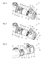
- FIG. 1 Figure 3 shows a schematic axonometric view of a disassemblable medical instrument or part of a disassemblable medical instrument 10 with a handle 12 in a proximal region of the collapsible medical instrument 10.
- Near the handle 12 are one or more buttons, pushbuttons, switches or other controls 14 and Valve operating lever 16 is arranged.
- the collapsible medical instrument 10 is in particular a shaver for mechanical and / or electrosurgical ablation of tissue.
- the operating elements 14 are provided for example for selecting an operating mode, for switching on and off a high voltage and / or a motor drive of an oscillating or rotating tool or for changing the frequency, the voltage or the rotational speed.
- the illustrated part of the collapsible medical instrument 10 comprises at its distal end (in FIG. 1 : Right) a substantially circular cylindrical coupling portion for mechanical coupling with a tool or with a proximal end of a shaft, the distal end of which has a tool or can be connected to a tool.
- the collapsible medical instrument 10 has, in the coupling region 18, a first section 51 of a fluid channel for aspirating ablated tissue.
- the first section 51 of the fluid channel extends in the axial direction of the substantially circular-cylindrical coupling region 18 FIG. 1 is only the entrance of the first, axial portion 51 of the fluid channel recognizable.
- the in FIG. 1 shown part of the collapsible medical instrument 10 has three components 20, 30, 40.
- a protruding region 21 is provided which comprises the coupling region 18.
- the second component 30 and the third component 40 are each of annular design and respectively enclose the protruding region 21.
- FIG. 1 shown part of the medical instrument 10 is destructible into the components 20, 30, 40 destructible and without the use of tools and can be easily and quickly assembled from the components 20, 30, 40 without the use of tools.
- the assembly of the components 20, 30, 40 is based on the FIGS. 2 to 5 shown.
- FIG. 2 shows a further schematic axonometric representation of the components 20, 30, 40 of the collapsible medical instrument 10 from FIG. 1 ,
- the components 20, 30, 40 spaced apart, but in the relative orientation in which they - as with reference to FIGS. 4 to 7 shown - can be assembled shown.
- the protruding region 21 on the first component 20 has - in particular of the features described below - essentially the shape of a circular cylinder with an axis of symmetry 60.
- the protruding region 21 on the first component 20 has, proximally of the coupling region 18 or between the handle 12 and the coupling region 18, two seals 22, 23 which surround the protruding region 21 in each case in an annular, in particular circular ring shape.
- the seals 22, 23 are, for example, O-rings in corresponding grooves which open in the axial direction or, as in the example shown, radially outward.
- each of the two seals can be adhesively bonded to the first component 20 by vulcanization.
- the projecting portion 21 of the first member 20 further includes one or more L-shaped grooves 24 each, of which in FIG. 2 one is visible and illustrated.
- the L-shaped groove 24 includes an axial portion 25 parallel to the axis of symmetry 60 of the protruding portion 21 and a portion 26 extending in the direction of the circumference of the protruding portion 21.
- the second component 30 is substantially annular and encloses a substantially circular cylindrical interior 39, the cross section of which substantially corresponds to the cross section of the protruding region 21 on the first component 20.
- the second component 30 has at its distal edge one or more respective arcuate and radially outwardly projecting webs 34, of which in FIG. 2 one is visible and shown.
- the second component 30 has a latching device 38 on its distal side and on the third component 40.
- the latching device 38 includes, for example, a ball in a bore which is movable in the bore parallel to the axis of symmetry 60, but by positive engagement on a complete exit the bore is prevented and pushed by a spring into a position in which the ball protrudes partially out of the bore.
- the third component 40 comprises one or more arcuate and radially inwardly projecting webs 43, of which in FIG. 2 only one is visible and shown.
- the circular-arc-shaped webs 34 on the second component 30 and the circular-arc-shaped webs 43 on the third component 40 are designed and arranged correspondingly such that the webs 34, 43 engage behind one another to form a positive connection between the second component 30 and the third component 40.
- two webs are arranged opposite each other both on the second component 30 and on the third component 40, each extending over slightly less than 90 degrees.
- the webs 34 on the second component 30 and the corresponding webs 43 on the third component 40 thus together form a first Renkhrss observed for forming a first RenkMIS between the second component 30 and the third component 40th
- each lug 42 on the third component 40 correspond in their shape and their arrangement to the L-shaped grooves 24 on the first component 20.
- a first, axial portion 51 of a fluid channel is provided, which is parallel or substantially parallel to the axis of symmetry 60 of the protruding region 21 on the first component 20 over the entire length or a large part of the length of the protruding portion 21 extends on the first member 20.
- the first, axial section 51 of the fluid channel has in particular a circular or substantially circular cross section.
- a second, radial portion 52 of the fluid channel extends orthogonal to the axis of symmetry 60 of the protruding region 21 on the first component 20 from the first portion 51 to an opening 53 between the seals 22, 23 on the protruding portion 21 on the first component 20.
- two opposing second radial portions 52 of the fluid channel are provided which terminate in two opposing openings 53 at the projecting portion 21 of the first member 20.
- the two second, radial sections 52 of the fluid channel are formed, in particular, by a through-hole or through-hole which extends orthogonally to the axis of symmetry 60 of the protruding region 21 on the first component 20.
- the fluid channel 51, 52 within the protruding region 21 on the first component 20 thus has a T-shaped configuration.
- a valve 54 is provided, which can be opened and closed by pivoting the valve actuating lever 16 about a pivot axis orthogonal to the axis of symmetry 60 of the projecting portion 21 on the first component 20.
- a pipe stub 55 is provided, which in FIG. 2 is almost completely obscured.
- the pipe socket 55 extends parallel or substantially parallel to the axis of symmetry 60 of the protruding region 21 on the first component 20.
- a substantially L-shaped section of the fluid channel is arranged FIG. 2 is not visible, in which the valve 54 and the pipe supports 55 are located.
- an opening 57 which corresponds to the pipe socket 55 on the second component 30, is provided on an end face facing the second component 30.
- the pipe socket 55 on the second component 30 engages in the opening 57 on the first component 20, and the mentioned L-shaped portion in the second component 30 connects the second, radial portion 52 of the fluid channel with the opening 57 in the first component 20.
- the composite The medical instrument 10 thus has a fluid channel, the components of which are the first, axial section 51, the second or the radial sections 52, the valve 54, the pipe socket 55 and the opening 57 in the first component 20.
- the fluid channel can be closed or interrupted and opened or made continuous.
- a suction effect on the medical instrument 10 can be switched on and off by means of the valve actuating lever 16 and the valve 54.
- the valve 54 may be configured so that the suction effect is infinitely or in stages adjustable.
- FIG. 3 shows a schematic representation of the third component 40 of the basis of the Figures 1 and 2 represented medical instruments 10.
- the second component 30 facing end face of the third component 40 visible.
- the ring-like or essentially annular third component 40 encloses a substantially circular or circular-cylindrical interior 49 whose cross-section substantially corresponds to the cross-section of the protruding region 21 on the first component 20.
- Two lugs 42 on the 40 protrude into the interior 40.
- Two opposite, each arcuate and inwardly projecting webs 43 each take an angle of almost 90 degrees and are separated by two gaps, each extending over a little more than 90 degrees ,
- the second component 30 (see. FIG. 2 ) to be facing end face a first recess 47 and a second recess 48 are provided, which in terms of their shape and their arrangement to the latching device 38 on the second component 30 (see. FIG. 2 ) correspond.
- FIG. 4 shows a further schematic axonometric representation of the components 20, 30, 40 from the FIGS. 1 to 3 .
- the type of representation corresponds to that of the Figures 1 and 2 ,
- FIG. 4 configuration shown differs from that in FIG. 2 shown in that the third component 40 is brought by a first pure translational movement parallel to the axis of symmetry 60 relative to the second component 30 in a first predetermined position relative to the second component 30.
- the first translation movement is in FIG. 2 indicated by an arrow 61.
- the second component 30 and the third component 40 are not yet mechanically positively connected to each other, but can be separated by a pure translational movement again.
- FIG. 5 shows a further schematic axonometric view of the collapsible medical instrument 10 of the FIGS. 1 to 4 .
- the type of representation corresponds to that of the FIGS. 1, 2 and 4 ,
- FIG. 5 the already mentioned second predetermined position of the third component 40 relative to the second component 30 is shown.
- the radially inwardly projecting webs 43 engage behind the third component 40, the radially outwardly projecting webs 34 on the second component 30 (see. FIGS. 2 and 3 ) partially.
- a form-fitting mechanical connection namely a first recessed connection, is produced between the second component 30 and the third component 40, which can not be separated again by a purely translatory relative movement.
- the second component 30 and the third component 40 form an assembly.
- FIG. 6 shows a further schematic axonometric representation of the first component 20 and the assembly formed from the second component 30 and the third component 40 from a slightly different perspective or viewing direction.
- the pipe socket 55 is visible on the end face of the second component 30 facing the first component 20.
- a seal 56 made of an elastomer or other elastic material is provided, which is connected by vulcanization cohesively with the second component 30, for example.
- the seal 56 forms almost the entire outer surface of the pipe socket 55 or at least a part thereof.
- the entire outer surface or the part of the outer surface of the pipe socket 55 formed by the seal 56 is, for example, conical or has the shape of a section of a lateral surface of a circular cone.
- the outer contour of the cross section of Seal 56 or the entire pipe socket for example, have steps or be formed step-shaped.
- the seal 56 when assembled in the intended manner medical instrument 10 (see. FIG. 1 ) the seal 56 in several narrow annular regions at the edge of the opening 57 (see. Figures 2 . 4, 5 ) issue. Thereby, the sealing effect of the seal 56 can be improved.
- the seal 56 can optionally effect a tolerance compensation between the first component 20 and the second component 30.
- the first component 20 and the second component 30 are in particular designed such that they have a predetermined clearance in order to be able to be put together with low friction. This game can be canceled by the elasticity of the seal 56 partially or completely.
- the assembly of the second component 30 and the third component 40 may be replaced by a second, pure translational movement shown in FIG. 5 is indicated by an arrow 63, are attached to the first component 20.
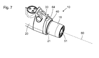
- FIG. 7 shows a further schematic axonometric representation of the components 20, 30, 40 from the FIGS. 1 to 6 .
- the type of representation corresponds to that of the FIGS. 1, 2 . 4 and 5 ,
- FIG. 7 the configuration shown starting from the in the FIGS. 5 and 6 as shown by the arrow 63 in FIG. 5 indicated second translational movement of the assembly of the second component 30 and the third component 40 is achieved relative to the first component 20.
- the lugs 42 on the third component 40 (see. FIGS. 2 to 5 ) is moved in the axial portions 25 of the L-shaped grooves 24.
- FIG. 7 illustrated configuration engages the pipe socket 55 on the second component 30 (see. FIG. 6 ) in the opening 57 on the first component 20 (see. Figures 2 . 4 and 5 ), and the seal 56 on the second component 30 sealingly abuts in one or more annular regions at the edge of the opening 57 on the first component 20. Furthermore, lies in the in FIG. 7 configuration shown, the wall surface of the substantially circular cylindrical interior 39 of the second component 30 (see, in particular Figures 2 and 6 ) on the seals 22, 23 at the projecting portion 21 on the first component 20 (see. Figures 2 . 4, 5 and 6 ) sealing. Thus, the aforementioned fluid channel inside the medical instrument 10 is completely manufactured and sealed from the outside world.
- the assembly of the second component 30 and the third component 40 can be separated from the first component 20 by a simple translational movement parallel to the axis of symmetry 60 of the protruding region 21 on the first component 20.
- the lugs 42 on the third component 40 (see FIG. FIGS. 2 to 5 ) is moved only in the axial portions 25 of the L-shaped grooves 24.
- the third component 40 may be connected to the first component 20 by a second rotational movement 64, indicated by an arrow 64, relative to the first component 20 and to the second component 30.
- the lugs 42 on the third component 40 (see. FIGS. 2 to 5 ) is moved in the direction of the circumference of the protruding portion 21 of the first member 20 extending portions 26 of the L-shaped grooves 24 in, and the third member 40 reaches the in FIG. 1 shown third predetermined position relative to the first component 20 and the second component 30th
- the first component 20 and the third component 40 are also mechanically rigidly connected to one another indirectly.
- the arrangement of the second component 30 between the first component prevent 20 and the third component 40 is a translational movement and the positive connection between the pipe socket 55 on the second component 30 and the opening 57 in the first component 20, a rotational movement of the second component 30 relative to the first component 20th
Abstract
Ein zerlegbares medizinisches Instrument (10) umfasst ein erstes Bauteil (20), ein zweites Bauteil (30), ein drittes Bauteil (40), eine erste Renkverbindungseinrichtung (34, 43) zum lösbaren mechanischen Verbinden des dritten Bauteils (40) mit dem zweiten Bauteil (30) durch eine erste Renkverbindung und eine zweite Renkverbindungseinrichtung (24, 42) zum lösbaren mechanischen Verbinden des dritten Bauteils (40) mit dem ersten Bauteil (20) durch eine zweite Renkverbindung. Bei einer ersten vorbestimmten Position des dritten Bauteils (40) relativ zu dem zweiten Bauteil (30) ist das dritte Bauteil (40) nicht mit dem zweiten Bauteil (30) verbunden. Bei einer zweiten vorbestimmten Position des dritten Bauteils (40) relativ zu dem zweiten Bauteil (30) ist das dritte Bauteil (40) durch die erste Renkverbindung mit dem zweiten Bauteil (30) mechanisch verbunden, und das zweite Bauteil (30) und das dritte Bauteil (40) sind nicht mit dem ersten Bauteil (20) verbunden. Bei einer dritten vorbestimmten Position des dritten Bauteils (40) relativ zu dem zweiten Bauteil (30) und zu dem ersten Bauteil (20) ist das dritte Bauteil (40) durch die erste Renkverbindung mit dem zweiten Bauteil (30) und durch die zweite Renkverbindung mit dem ersten Bauteil (20) mechanisch starr verbunden.A collapsible medical instrument (10) comprises a first component (20), a second component (30), a third component (40), a first hinge connection device (34, 43) for releasably mechanically connecting the third component (40) to the second Component (30) by a first Renkverbindung and a second Renkverbindungseinrichtung (24, 42) for releasably mechanically connecting the third component (40) with the first component (20) by a second Renkverbindung. At a first predetermined position of the third component (40) relative to the second component (30), the third component (40) is not connected to the second component (30). In a second predetermined position of the third component (40) relative to the second component (30), the third component (40) is mechanically connected to the second component (30) by the first hinge connection, and the second component (30) and the third Component (40) are not connected to the first component (20). At a third predetermined position of the third component (40) relative to the second component (30) and to the first component (20), the third component (40) is connected to the second component (30) through the first recessed connection and through the second recessed connection mechanically rigidly connected to the first component (20).
Description
Die vorliegende Erfindung ist auf ein zerlegbares medizinisches Instrument, insbesondere auf ein zerlegbares medizinisches Instrument mit einem integrierten Fluidkanal, durch den beispielsweise abgetragenes Gewebe abgesaugt werden kann, bezogen.The present invention relates to a disassemblable medical instrument, in particular a dismountable medical instrument having an integrated fluid channel, through which, for example, removed tissue can be aspirated.
Shaver und andere medizinische Instrumente zum mechanischen und/oder elektrochirurgischen Abtragen von Gewebe weisen oft einen integrierten Fluidkanal zum Spülen des Operationsorts oder zum Absaugen von abgetragenem Gewebe auf. Zur Steuerung des Fluidflusses und damit der Spül- oder Absaugwirkung kann ein Ventil vorgesehen sein. Insbesondere wenn durch den Fluidkanal abgetragenes Gewebe abgesaugt wird, ist eine gründliche mechanische Reinigung nach jeder Verwendung des medizinischen Instruments einschließlich des Fluidkanals erforderlich. Dies gilt besonders für ein im Fluidkanal vorgesehenes Ventil mit seinen vergleichsweise komplex geformten Oberflächen.Shaver and other medical instruments for mechanical and / or electrosurgical ablation of tissue often have an integral fluid channel for flushing the surgical site or for aspirating ablated tissue. To control the fluid flow and thus the rinsing or suction, a valve may be provided. In particular, when tissue removed through the fluid channel is aspirated, thorough mechanical cleaning is required after each use of the medical instrument, including the fluid channel. This applies in particular to a valve provided in the fluid channel with its comparatively complex shaped surfaces.
Eine Aufgabe der vorliegenden Erfindung besteht darin, ein verbessertes zerlegbares medizinisches Instrument zu schaffen, das insbesondere auf möglichst einfache Weise möglichst weitgehend zerlegbar ist, um eine vollständige Reinigung zu vereinfachen.An object of the present invention is to provide an improved collapsible medical instrument, which is as far as possible dismantled in the simplest possible way, in order to simplify a complete cleaning.
Diese Aufgabe wird durch den Gegenstand des unabhängigen Anspruchs gelöst.This object is solved by the subject matter of the independent claim.
Weiterbildungen sind in den abhängigen Ansprüchen angegeben.Further developments are specified in the dependent claims.
Ein zerlegbares medizinisches Instrument umfasst ein erstes Bauteil, ein zweites Bauteil, ein drittes Bauteil, eine erste Renkverbindungseinrichtung zum lösbaren mechanischen Verbinden des dritten Bauteils mit dem zweiten Bauteil durch eine erste Renkverbindung und eine zweite Renkverbindungseinrichtung zum lösbaren mechanischen Verbinden des dritten Bauteils mit dem ersten Bauteil durch eine zweite Renkverbindung, wobei bei einer ersten vorbestimmten Position des dritten Bauteils relativ zu dem zweiten Bauteil das dritte Bauteil nicht mit dem zweiten Bauteil verbunden ist, wobei bei einer zweiten vorbestimmten Position des dritten Bauteils relativ zu dem zweiten Bauteil das dritte Bauteil durch die erste Renkverbindung mit dem zweiten Bauteil mechanisch verbunden ist und das zweite Bauteil und das dritte Bauteil nicht mit dem ersten Bauteil verbunden sind, und wobei bei einer dritten vorbestimmten Position des dritten Bauteils relativ zu dem zweiten Bauteil und zu dem ersten Bauteil das dritte Bauteil durch die erste Renkverbindung mit dem zweiten Bauteil und durch die zweite Renkverbindung mit dem ersten Bauteil mechanisch starr verbunden ist.A collapsible medical instrument comprises a first component, a second component, a third component, a first Renkverbindungseinrichtung for releasably mechanically connecting the third component to the second component by a first Renkverbindung and a second Renkverbindungseinrichtung for releasably mechanically connecting the third component with the first component by a second Renkverbindung, wherein at a first predetermined position of the third component relative to the second component, the third component is not connected to the second component, wherein at a second predetermined position of the third component relative to the second component, the third component through the first Renkverbindung is mechanically connected to the second component and the second component and the third component are not connected to the first component, and wherein at a third predetermined position of the third component relative to the second component and to the first component the third component is mechanically rigidly connected to the first component by the first recessed connection and to the first component by the second recessed connection.
Ein zerlegbares medizinisches Instrument umfasst ein erstes Bauteil, ein zweites Bauteil, ein drittes Bauteil, das mit dem zweiten Bauteil derart dauerhaft mechanisch verbunden ist, dass das dritte Bauteil relativ zu dem zweiten Bauteil rotierbar ist, und eine Renkverbindungseinrichtung zum lösbaren mechanischen Verbinden des dritten Bauteils mit dem ersten Bauteil durch eine Renkverbindung, wobei bei einer ersten vorbestimmten Position des dritten Bauteils relativ zu dem ersten Bauteil das dritte Bauteil nicht mit dem ersten Bauteil verbunden ist, und wobei bei einer zweiten vorbestimmten Position des dritten Bauteils relativ zu dem ersten Bauteil das dritte Bauteil durch die Renkverbindung mit dem ersten Bauteil mechanisch starr verbunden ist.A collapsible medical instrument comprises a first component, a second component, a third component which is permanently mechanically connected to the second component in such a way that the third component is rotatable relative to the second component, and a reverse connection device for the detachable mechanical connection of the third component with the first component by a Renkverbindung, wherein at a first predetermined position of the third component relative to the first component, the third component is not connected to the first component, and wherein at a second predetermined position of the third component relative to the first component, the third Component is mechanically rigidly connected by the Renkverbindung with the first component.
Das dritte Bauteil ist mit dem zweiten Bauteil insbesondere derart dauerhaft mechanisch verbunden, dass das dritte Bauteil relativ zu dem zweiten Bauteil rotierbar ist. Das erste Bauteil und das zweite Bauteil sind insbesondere so ausgebildet, dass es nur eine vorbestimmte Position des zweiten Bauteils relativ zu dem ersten Bauteil gibt, in der das dritte Bauteil die erste vorbestimmte Position und die zweite vorbestimmte Position relativ zu dem ersten Bauteil erreichen kann. In diesem Fall sind die erste vorbestimmte Position des dritten Bauteils relativ zu dem ersten Bauteil auch eine erste vorbestimmte Position des dritten Bauteils relativ zu dem zweiten Bauteil und die zweite vorbestimmte Position des dritten Bauteils relativ zu dem ersten Bauteil auch eine zweite vorbestimmte Position des dritten Bauteils relativ zu dem zweiten Bauteil. Die Renkverbindung und die Renkverbindungseinrichtung des zuletzt genannten zerlegbaren medizinischen Instruments entsprechen der zweiten Renkverbindung bzw. der zweiten Renkverbindungseinrichtung der nachfolgend dargestellten Ausführungsformen und Varianten.The third component is in particular mechanically permanently connected to the second component such that the third component is rotatable relative to the second component. In particular, the first component and the second component are configured such that there is only one predetermined position of the second component relative to the first component, in which the third component can reach the first predetermined position and the second predetermined position relative to the first component. In this case, the first predetermined position of the third component relative to the first component is also a first predetermined position of the third component relative to the second component and the second predetermined position of the third component relative to the first component is also a second predetermined position of the third component relative to the second component. The Renkverbindung and the Renkverbindungseinrichtung of the last-mentioned dismountable medical instrument Correspond to the second and the second Renkverbindung Renkverbindungseinrichtung the embodiments and variants shown below.
Das zerlegbare medizinische Instrument ist insbesondere ein Shaver oder ein anderes medizinisches Instrument zum Abtragen von Gewebe auf mechanischem und/oder elektrochirurgischem Weg. Das erste Bauteil umfasst insbesondere einen Handgriff oder eine Handhabe zum manuellen Halten, Führen und Bewegen des zerlegbaren medizinischen Instruments während seines vorgesehenen Einsatzes bzw. seiner vorgesehenen Verwendung im Rahmen einer medizinischen Maßnahme. Das medizinische Instrument ist vorgesehen und ausgebildet, um nach jeder Verwendung weitgehend zerlegt zu werden, wobei insbesondere das erste Bauteil, das zweite Bauteil und das dritte Bauteil zerstörungsfrei voneinander getrennt werden können. Im zerlegten Zustand kann das medizinische Instrument weitgehend oder vollständig gereinigt werden. Dazu trägt bei, dass Oberflächen, die bei der zusammengesetzten Konfiguration zwischen dem ersten Bauteil und dem zweiten Bauteil oder zwischen dem zweiten Bauteil und dem dritten Bauteil oder zwischen dem ersten Bauteil und dem dritten Bauteil liegen, im zerlegten Zustand offen liegen. Dabei liegen insbesondere auch Oberflächen von Fluidkanälen oder anderen Hohlräumen des medizinischen Instruments offen und sind einer unmittelbaren manuellen oder maschinellen Reinigung zugänglich.The collapsible medical instrument is in particular a shaver or another medical instrument for ablating tissue by mechanical and / or electrosurgical means. The first component in particular comprises a handle or a handle for manually holding, guiding and moving the collapsible medical instrument during its intended use or its intended use as part of a medical procedure. The medical instrument is provided and designed to be largely disassembled after each use, in particular, the first component, the second component and the third component can be separated from each other without destroying each other. When disassembled, the medical instrument can be largely or completely cleaned. Contributing to this is that surfaces lying in the assembled configuration between the first component and the second component or between the second component and the third component or between the first component and the third component are in the disassembled state. In particular, surfaces of fluid channels or other cavities of the medical instrument are also open and are accessible to immediate manual or mechanical cleaning.
Eine Renkverbindung (oft auch als Bajonettverbindung oder Bajonettkupplung bezeichnet) ist eine formschlüssige und in der Regel lösbare ohne Verwendung von Werkzeug zerstörungsfrei lösbare mechanische Verbindung zwischen zwei Bauteilen. Eine Renkverbindung wird hergestellt, indem die Bauteile zunächst durch eine Translationsbewegung (in der Regel eine reine Translationsbewegung ohne damit einhergehender Rotationsbewegung) aneinander angenähert und danach relativ zueinander rotiert werden. Durch einen umgekehrten Bewegungsablauf - zunächst Rotation, dann Translation - können die beiden Bauteile wieder voneinander getrennt werden.A Renkverbindung (often referred to as a bayonet connection or bayonet coupling) is a positive and usually releasable without the use of tools destructive releasable mechanical connection between two components. A Renkverbindung is prepared by the components first by a translational movement (usually a pure translational movement without associated rotational movement) approached to each other and then rotated relative to each other. By a reverse movement sequence - first rotation, then translation - the two components can be separated again.
Die erste Renkverbindungseinrichtung umfasst insbesondere eine oder mehrere Knaggen, Stege oder Nuten an einem der beiden beteiligten Bauteile, die ausgebildet, angeordnet und vorgesehen sind, um Knaggen oder Stege am anderen beteiligten Bauteil zu hintergreifen oder in Nuten am anderen beteiligten Bauteil einzugreifen. Insbesondere weist jeweils eines der beiden beteiligten Bauteile nach radial innen ragende Knaggen oder Stege auf, die hinter korrespondierende, nach radial außen ragende Knaggen oder Stege oder in eine oder mehrere nach radial außen offene Nuten am anderen beteiligten Bauteil eingreifen können.The first Renkverbindungseinrichtung comprises in particular one or more lugs, webs or grooves on one of the two components involved, which are formed, arranged and provided to engage behind lugs or ridges on the other component involved or engage in grooves on the other component involved. In particular, one of the two components involved in each case has radially inwardly projecting lugs or webs, which can engage behind corresponding, radially outwardly projecting lugs or webs or in one or more radially outwardly open grooves on the other component involved.
Nach der Reinigung des medizinischen Instruments können das erste Bauteil, das zweite Bauteil und das dritte Bauteil in einer vorgesehenen Weise zusammengesetzt werden, um die vorgesehene Funktionalität des medizinischen Instruments herzustellen. Dies ist nachfolgend für das medizinische Instrument beschrieben, bei dem das zweite Bauteil und das dritte Bauteil nicht dauerhaft, sondern durch eine erste Renkverbindung miteinander verbunden sind. Bein dem medizinischen Instrument, bei dem das zweite Bauteil und das dritte Bauteil dauerhaft mechanische verbunden sind, entfallen Schritte zur Herstellung der ersten Renkverbindung zwischen dem zweiten Bauteil und dem dritten Bauteil.After cleaning the medical instrument, the first component, the second component, and the third component may be assembled in a suitable manner to produce the intended functionality of the medical instrument. This is described below for the medical instrument, in which the second component and the third component are not permanently connected to one another but by a first recessed connection. In the medical instrument, in which the second component and the third component are permanently connected to a mechanical instrument, steps for producing the first recessed connection between the second component and the third component are omitted.
Zum Zusammensetzen des medizinischen Instruments ist es insbesondere vorgesehen, zunächst das dritte Bauteil in einer ersten vorbestimmten Position an das zweite Bauteil anzusetzen. Die erste vorbestimmte Position umfasst eine erste vorbestimmte Winkelposition bzw. räumliche Orientierung des dritten Bauteils relativ zu dem zweiten Bauteil, in der das dritte Bauteil durch eine erste, insbesondere geradlinige reine Translationsbewegung (ohne damit einhergehende Rotationsbewegung) an das zweite Bauteil angenähert wird bis das dritte Bauteil die erste vorbestimmte Position relativ zu dem zweiten Bauteil erreicht hat.In order to assemble the medical instrument, it is provided, in particular, to initially attach the third component to the second component in a first predetermined position. The first predetermined position comprises a first predetermined angular position or spatial orientation of the third component relative to the second component, in which the third component is approximated to the second component by a first, in particular rectilinear, pure translational movement (without associated rotational movement) until the third component Component has reached the first predetermined position relative to the second component.
Ausgehend von der ersten vorbestimmten Position kann das dritte Bauteil durch eine erste reine Rotationsbewegung um eine vorbestimmte Rotationsachse in die zweite vorbestimmte Position relativ zu dem zweiten Bauteil gebracht werden. In der zweiten vorbestimmten Position des dritten Bauteils relativ zu dem zweiten Bauteil sind das dritte Bauteil und das zweite Bauteil insofern mechanisch miteinander verbunden, als sie nicht mehr durch eine rein translatorische Bewegung voneinander trennbar sind. Die Rotationsachse der ersten Rotationsbewegung ist insbesondere parallel zu der Richtung der vorangehenden ersten Translationsbewegung. Mit der ersten Translationsbewegung und der nachfolgenden ersten Rotationsbewegung wird die erste Renkverbindung zwischen dem dritten Bauteil und dem zweiten Bauteil hergestellt.Starting from the first predetermined position, the third component can be brought by a first pure rotational movement about a predetermined axis of rotation in the second predetermined position relative to the second component. In the second predetermined position of the third component relative to the second component, the third component and the second component are mechanically interconnected insofar as they are no longer separable from each other by a purely translational movement. The axis of rotation of the first rotational movement is in particular parallel to the direction of the preceding first translational movement. With the first translational movement and the subsequent first rotational movement, the first recessed connection between the third component and the second component is produced.
Wenn das dritte Bauteil durch die erste Renkverbindung mit dem zweiten Bauteil mechanisch verbunden ist, können das zweite Bauteil und das dritte Bauteil als Baugruppe gemeinsam an das erste Bauteil herangeführt werden. Dies erfolgt insbesondere in einer zweiten geradlinigen reinen Translationsbewegung in einer Richtung parallel zur Rotationsachse der ersten Renkverbindung. Bei dieser reinen Translationsbewegung erreicht das zweite Bauteil relativ zu dem ersten Bauteil insbesondere bereits seine endgültige und für die vorgesehene Verwendung des medizinischen Instruments vorbestimmte Position relativ zu dem ersten Bauteil.If the third component is mechanically connected to the second component by the first recessed connection, the second component and the third component can be brought together as an assembly to the first component. This is done in particular in a second straight pure translation movement in a direction parallel to the axis of rotation of the first Renkverbindung. In this pure translation movement, the second component relative to the first component in particular already reaches its final and predetermined for the intended use of the medical instrument position relative to the first component.
Mit einer nachfolgenden zweiten Rotationsbewegung des dritten Bauteils relativ zu dem zweiten Bauteil und zu dem ersten Bauteil wird die zweite Renkverbindung zwischen dem dritten Bauteil und dem ersten Bauteil hergestellt. Die Rotation erfolgt insbesondere um die Rotationsachse der ersten Renkverbindung. Mit dieser zweiten Rotationsbewegung erreicht das dritte Bauteil die dritte vorbestimmte Position relativ zu dem zweiten Bauteil und zu dem ersten Bauteil, in der es durch die erste Renkverbindung mit dem zweiten Bauteil und durch die zweite Renkverbindung mit dem ersten Bauteil mechanisch verbunden ist.With a subsequent second rotational movement of the third component relative to the second component and to the first component, the second recessed connection between the third component and the first component is produced. The rotation takes place in particular about the axis of rotation of the first Renkverbindung. With this second rotational movement, the third component reaches the third predetermined position relative to the second component and to the first component, in which it is mechanically connected to the first component by the first recessed connection and to the first component by the second recessed connection.
Die Ausbildung des zerlegbaren medizinischen Instruments mit drei Bauteilen, die durch zwei Renkverbindungen miteinander verbindbar sind, kann eine sehr weitgehende Zerlegung und damit eine weitgehende Offenlegung innerer Oberflächen des medizinischen Instruments und damit eine einfache und vollständige Reinigung ermöglichen. Die lösbare mechanische Verbindung der Bauteile durch Renkverbindungen kann eine einfache und schnelle Zerlegung und nachfolgende Zusammensetzung des medizinischen Instruments auch durch ungeübtes Personal ermöglichen.The design of the dismountable medical instrument with three components, which can be connected to one another by means of two recesses, can enable a very extensive disassembly and thus a substantial disclosure of internal surfaces of the medical instrument and thus a simple and complete cleaning. The detachable mechanical connection of the components by means of recessed joints can allow easy and quick disassembly and subsequent composition of the medical instrument even by untrained personnel.
Die erste Renkverbindung zwischen dem dritten Bauteil und dem zweiten Bauteil verhindert, dass gleichzeitig drei nicht miteinander verbundene Bauteile gehandhabt werden müssen. Vielmehr müssen jederzeit höchstens zwei Bauteile oder in sich zusammenhängende Baugruppen gehalten und relativ zueinander bewegt werden, nämlich zunächst das zweite Bauteil und das dritte Bauteil und danach das erste Bauteil und die Baugruppe aus dem zweiten Bauteil und dem dritten Bauteil.The first hinge connection between the third component and the second component prevents three unconnected components from having to be handled at the same time. Rather, no more than two components or related assemblies must be held and moved relative to each other at any time, namely first the second component and the third component and then the first component and the assembly of the second component and the third component.
Durch die indirekte mechanische Verbindung zwischen dem ersten Bauteil und dem zweiten Bauteil über das dritte Bauteil müssen das erste Bauteil und das zweite Bauteil zu keinem Zeitpunkt relativ zueinander rotiert werden. Dies schafft zusätzliche konstruktive Freiheitsgrade, beispielsweise kann das zweite Bauteil in einer Weise in das erste Bauteil eingreifen, die eine Rotation des zweiten Bauteils relativ zu dem ersten Bauteil nicht zulässt und damit eine unmittelbare Renkverbindung zwischen dem ersten Bauteil und dem zweiten Bauteil verhindert würde.Due to the indirect mechanical connection between the first component and the second component via the third component, the first component and the second component need not be rotated relative to each other at any time. This provides additional structural degrees of freedom, for example, the second component can engage in a manner in the first component, which does not allow rotation of the second component relative to the first component and thus an immediate Renkverbindung between the first component and the second component would be prevented.
Bei einem zerlegbaren medizinischen Instrument, wie es hier beschrieben ist, ist am in der vorgesehenen Weise funktionsfähig zusammengesetzten medizinischen Instrument insbesondere das zweite Bauteil zwischen dem ersten Bauteil und dem dritten Bauteil angeordnet.In a collapsible medical instrument, as described here, in particular the second component is arranged between the first component and the third component on the medical instrument assembled in the intended manner.
Anders ausgedrückt ist das dritte Bauteil insbesondere an einer vom ersten Bauteil teilweise abgewandten Seite des zweiten Bauteils angeordnet. Mit einer Anordnung des zweiten Bauteils zwischen dem ersten Bauteil und dem dritten Bauteil bzw. einer Anordnung des dritten Bauteils an einer vom ersten Bauteil abgewandten Seite des zweiten Bauteil ist eine unmittelbare Berührung zwischen dem ersten Bauteil und dem dritten Bauteil nicht ausgeschlossen, wie sie tatsächlich im Bereich der zweiten Renkverbindungseinrichtung erfolgt.In other words, the third component is arranged, in particular, on a side of the second component which is partially remote from the first component. With an arrangement of the second component between the first component and the third component or an arrangement of the third component a side facing away from the first component side of the second component is not excluded direct contact between the first component and the third component, as is actually done in the region of the second Renkverbindungseinrichtung.
Die Anordnung des zweiten Bauteils zwischen dem ersten Bauteil und dem dritten Bauteil schafft insbesondere eine formschlüssige Definition des Orts des zweiten Bauteils und kann eine Bewegung des zweiten Bauteils relativ zu dem ersten Bauteil und zu dem dritten Bauteil weitgehend oder vollständig unterbinden.The arrangement of the second component between the first component and the third component in particular creates a positive definition of the location of the second component and can largely or completely prevent movement of the second component relative to the first component and to the third component.
Ein zerlegbares medizinisches Instrument, wie es hier beschrieben ist, umfasst insbesondere ferner eine Rasteinrichtung zum Halten des dritten Bauteils zumindest entweder in der zweiten vorbestimmten Position oder in der dritten vorbestimmten Position relativ zu dem zweiten Bauteil.In particular, a collapsible medical instrument as described here further comprises a latching device for holding the third component at least either in the second predetermined position or in the third predetermined position relative to the second component.
Die Rasteinrichtung umfasst insbesondere eine Ausnehmung oder Vertiefung und eine gegen die Rückstellkraft einer elastischen Einrichtung bewegbare und zur Ausnehmung oder Vertiefung korrespondierende vorstehende Einrichtung. Insbesondere sind die Ausnehmung oder Vertiefung am dritten Bauteil und die elastische Einrichtung und die vorstehende Einrichtung am zweiten Bauteil angeordnet. Alternativ sind die Ausnehmung oder Vertiefung am zweiten Bauteil und die elastische Einrichtung und die vorstehende Einrichtung am dritten Bauteil angeordnet. Die elastische Einrichtung umfasst beispielsweise eine Spiralfeder in einer Bohrung, wobei die vorstehende Einrichtung eine Kugel umfasst, die durch Formschluss an einem vollständigen Verlassen der Bohrung gehindert und durch die Feder in eine Position, in der sie teilweise aus der Bohrung hervorragt, gedrückt wird.The latching device comprises in particular a recess or depression and a protruding device which can be moved against the restoring force of an elastic device and which corresponds to the recess or depression. In particular, the recess or depression on the third component and the elastic device and the protruding device are arranged on the second component. Alternatively, the recess or recess on the second component and the elastic device and the protruding device are arranged on the third component. The resilient means comprises, for example, a coil spring in a bore, the protruding means comprising a ball which is positively constrained to completely leave the bore and is urged by the spring to a position partially protruding from the bore.
Die Rasteinrichtung vereinfacht das Zusammensetzen des zerlegbaren medizinischen Instruments insbesondere, indem sie das dritte Bauteil sowohl in der zweiten vorbestimmten Position als auch in der dritten vorbestimmten Position formschlüssig hält und ein unbeabsichtigtes Lösen der ersten Renkverbindung oder der zweiten Renkverbindung verhindert. Ferner schafft die Rasteinrichtung eine taktile und/oder hörbare Rückmeldung bei Erreichen der zweiten oder der dritten vorbestimmten Position, die das Zusammensetzen ebenfalls vereinfacht.In particular, the latch means facilitates assembly of the collapsible medical instrument by positively holding the third member both in the second predetermined position and in the third predetermined position and preventing unintentional release of the first turn link or the second turn link. Furthermore, the latching device provides a tactile and / or audible feedback upon reaching the second or third predetermined position, which also simplifies assembly.
Ein zerlegbares medizinisches Instrument, wie es hier beschrieben ist, umfasst insbesondere ferner eine Einrichtung zur Unterbindung einer Rotation des zweiten Bauteils relativ zu dem ersten Bauteil, wenn das dritte Bauteil sich in der dritten vorbestimmten Position befindet.In particular, a collapsible medical instrument as described herein further includes means for inhibiting rotation of the second member relative to the first member when the third member is in the third predetermined position.
Bei einem zerlegbaren medizinischen Instrument, wie es hier beschrieben ist, umfasst die Einrichtung zur Unterbindung einer Rotation insbesondere einen Rohrstutzen am zweiten Bauteil und eine korrespondierende Öffnung am ersten Bauteil oder einen Rohrstutzen am ersten Bauteil und eine korrespondierende Öffnung am zweiten Bauteil.In a collapsible medical instrument, as described here, the means for suppressing rotation comprises in particular a pipe socket on the second component and a corresponding opening on the first component or a pipe socket on the first component and a corresponding opening on the second component.
Alternativ umfasst die Einrichtung zur Unterbindung einer Rotation beispielsweise einen Stift oder eine Nase oder einen anderen konvexen Bereich am zweiten Bauteil, der bzw. die in eine korrespondierende Öffnung am ersten Bauteil eingreift oder einen Stift oder eine Nase oder einen anderen konvexen Bereich am ersten Bauteil, der bzw. die in eine korrespondierende Öffnung am zweiten Bauteil eingreift.Alternatively, the means for inhibiting a rotation comprises, for example, a pin or a nose or another convex portion on the second component, which engages in a corresponding opening on the first component or a pin or a nose or another convex portion on the first component, the or engages in a corresponding opening on the second component.
Eine Einrichtung zur Unterbindung einer Rotation des zweiten Bauteils relativ zu dem ersten Bauteil kann eine vorbestimmte Orientierung des zweiten Bauteils relativ zu dem ersten Bauteil bewirken und ein unbeabsichtigtes Lösen der zweiten Renkverbindung zwischen dem dritten Bauteil und dem ersten Bauteil verhindern. Ein Rohrstutzen und eine korrespondierende Öffnung können beispielsweise in einer Richtung parallel zur Rotationsachse der Renkverbindungen ineinander eingreifen, wobei der Rohrstutzen und die Öffnung nicht rotationssymmetrisch zur Rotationsachse sind. Insbesondere sind der Rohrstutzen und die Öffnung von der Rotationsachse der Renkverbindungen beabstandet.A device for suppressing rotation of the second component relative to the first component can bring about a predetermined orientation of the second component relative to the first component and prevent inadvertent release of the second hinge connection between the third component and the first component. A pipe socket and a corresponding opening can, for example, engage in one another in a direction parallel to the axis of rotation of the Renkverbindungen, wherein the pipe socket and the opening are not rotationally symmetrical to the axis of rotation. In particular, the pipe socket and the opening are spaced from the axis of rotation of the Renkverbindungen.
Ein Rohrstutzen und eine korrespondierende Öffnung können insbesondere eine fluidische Verbindung zwischen dem ersten Bauteil und dem zweiten Bauteil schaffen.A pipe socket and a corresponding opening can in particular create a fluidic connection between the first component and the second component.
Bei einem zerlegbaren medizinischen Instrument, wie es hier beschrieben ist, umfassen das erste Bauteil und das zweite Bauteil jeweils insbesondere einen oder mehrere Abschnitte eines Fluidkanals zum Transport eines Fluids, wobei die Abschnitte des Fluidkanals im zerlegten Zustand des medizinischen Instruments für eine Reinigung zugänglich sind.In a collapsible medical instrument as described here, the first component and the second component respectively comprise in particular one or more sections of a fluid channel for transporting a fluid, wherein the sections of the fluid channel are accessible for cleaning in the disassembled state of the medical instrument.
Insbesondere umfassen das erste Bauteil und das zweite Bauteil jeweils Teile eines Fluidkanals zum Transport eines aus einem Operationsgebiet abgesaugten Fluids, das beispielsweise abgetragenes Gewebe enthalten kann.In particular, the first component and the second component each comprise parts of a fluid channel for transporting a fluid extracted from an operating area, which may contain, for example, removed tissue.
Insbesondere bilden der oben erwähnte Rohrstutzen und die oben erwähnte Öffnung, in die der Rohrstutzen eingreifen kann, Teile eines Fluidkanals in dem medizinischen Instrument.In particular, the above-mentioned pipe socket and the above-mentioned opening, into which the pipe socket can engage, form parts of a fluid channel in the medical instrument.
Bei einem zerlegbaren medizinischen Instrument, wie es hier beschrieben ist, sind insbesondere das medizinische Instrument zum Abtragen von Gewebe und der Fluidkanal zum Absaugen von abgetragenem Gewebe vorgesehen und ausgebildet.In a collapsible medical instrument, as described here, in particular the medical instrument for removing tissue and the fluid channel for the suction of ablated tissue are provided and designed.
Das zerlegbare medizinische Instrument ist insbesondere ein Shaver mit einer Klinge oder einer Drahtschlaufe, an die eine hochfrequente Hochspannung angelegt werden kann, um Gewebe mechanisch und/oder elektrochirurgisch abzutragen. Die Klinge oder die Drahtschlaufe können durch einen in oder an der medizinischen Vorrichtung vorgesehenen Motor rotierbar sein.In particular, the collapsible medical instrument is a shaver with a blade or wire loop to which a high frequency high voltage can be applied to mechanically and / or electrosurgically ablate tissue. The blade or wire loop may be rotatable by a motor provided in or on the medical device.
Ein zerlegbares medizinisches Instrument, wie es hier beschrieben ist, umfasst insbesondere ferner ein Ventil zum teilweisen oder vollständigen Unterbrechen des Fluidkanals im zweiten Bauteil.A dismountable medical instrument, as described here, further comprises, in particular, a valve for partially or completely interrupting the fluid channel in the second component.
Das Ventil kann zum An- und Ausschalten, Verändern, Steuern oder Regeln der Absaugleistung oder - im Falle eines ein Spül-Fluid transportierenden Fluidkanals - der Spülleistung vorgesehen und ausgebildet sein. Durch die Zerlegbarkeit des medizinischen Instruments, insbesondere durch die Trennbarkeit des zweiten Bauteils vom ersten Bauteil können innere Oberflächen des Ventils freigelegt und einer mechanischen Reinigung zugänglich gemacht werden.The valve can be provided and designed for switching on and off, changing, controlling or regulating the suction power or, in the case of a fluid channel carrying a flushing fluid, the flushing power. Due to the dismantling of the medical instrument, in particular by the separability of the second component of the first component inner surfaces of the valve can be exposed and made a mechanical cleaning accessible.
Bei einem zerlegbaren medizinischen Instrument, wie es hier beschrieben ist, weist das erste Bauteil insbesondere einen vorstehenden Bereich auf, wobei das zweite Bauteil im Wesentlichen ringartig ist, und wobei am in der vorgesehenen Weise funktionsfähig zusammengesetzten medizinischen Instrument das zweite Bauteil den vorstehenden Bereich am ersten Bauteil umschließt.In a collapsible medical instrument, as described here, the first component in particular has a protruding area, wherein the second component is substantially ring-like, and wherein on the intended manner assembled medical instrument, the second component of the projecting area on the first Encloses component.
Bei einem zerlegbaren medizinischen Instrument, wie es hier beschrieben ist, ist das dritte Bauteil insbesondere im Wesentlichen ringartig, wobei am in der vorgesehenen Weise funktionsfähig zusammengesetzten medizinischen Instrument das dritte Bauteil den vorstehenden Bereich am ersten Bauteil umschließt.In a collapsible medical instrument, as described here, the third component is in particular substantially ring-like, wherein the third component surrounds the projecting area on the first component on the medical instrument assembled in the intended manner.
Ein Bauteil ist ringartig, wenn es in mathematischem Sinne mehrfach (insbesondere zweifach) zusammenhängend ist bzw. die Topologie eines Kreisrings aufweist. Das Bauteil muss dabei weder kreisringförmig sein noch beispielsweise die Gestalt eines Torus aufweisen. Ein ringartiges Bauteil weist jedoch eine das Bauteil vollständig durchdringende Öffnung auf, in die der vorstehende Bereich am ersten Bauteil eingeführt werden kann.A component is ring-like if, in the mathematical sense, it is multiply (in particular two-fold) connected or has the topology of a circular ring. The component does not have to be circular or have the shape of a torus, for example. However, a ring-like member has an opening completely penetrating the member, into which the projecting portion can be inserted on the first member.
Bei einem zerlegbaren medizinischen Instrument, wie es hier beschrieben ist, umschließen das zweite Bauteil und das dritte Bauteil in ihrer durch die erste Renkverbindung verbundenen Konfiguration insbesondere einen im Wesentlichen kreiszylindrischen Innenraum.In a collapsible medical instrument, as described here, the second component and the third component, in their configuration connected by the first recessed connection, in particular enclose a substantially circular-cylindrical interior.
Der vorstehende Bereich am ersten Bauteil weist insbesondere eine zu dem vom zweiten Bauteil und vom dritten Bauteil umschlossenen Innenraum korrespondierende Gestalt auf.The projecting area on the first component has, in particular, a shape corresponding to the interior space enclosed by the second component and by the third component.
Die Rotationsachse der Renkverbindungen und die Translationsrichtungen der Renkverbindungen sind insbesondere parallel zu oder identisch mit einer Längsachse oder einer Symmetrieachse des vorstehenden Bereichs am ersten Bauteil.The axis of rotation of the recessed joints and the translational directions of the recessed joints are in particular parallel to or identical to a longitudinal axis or an axis of symmetry of the projecting area on the first component.
Bei einem zerlegbaren medizinischen Instrument, wie es hier beschrieben ist, sind insbesondere in dem vorstehenden Bereich ein erster Abschnitt des Fluidkanals im Wesentlichen parallel zur Längsachse des vorstehenden Bereichs und ein zweiter Abschnitt des Fluidkanals im Wesentlichen orthogonal zur Längsachse des vorstehenden Bereichs angeordnet.In a collapsible medical instrument as described herein, particularly in the protruding area, a first portion of the fluid channel is arranged substantially parallel to the longitudinal axis of the protruding area and a second portion of the fluid channel is substantially orthogonal to the longitudinal axis of the protruding area.
Der vorstehende Bereich am ersten Bauteil enthält also insbesondere einen L-förmigen oder T-förmigen Teil des Fluidkanals.The projecting area on the first component thus contains, in particular, an L-shaped or T-shaped part of the fluid channel.
Ein zerlegbares medizinisches Instrument, wie es hier beschrieben ist, umfasst insbesondere ferner zwei jeweils ringartig den vorstehenden Bereich am ersten Bauteil umschließende Dichtungen, wobei der zweite Abschnitt des Fluidkanals in einer Öffnung zwischen den Dichtungen endet.In particular, a collapsible medical instrument, as described here, further comprises two gaskets each enclosing the protruding region on the first component, wherein the second section of the fluid channel terminates in an opening between the gaskets.
Die den vorstehenden Bereich am ersten Bauteil jeweils ringartig umschließenden Dichtungen sind beispielsweise O-Ringe in entsprechenden ringförmigen, nach außen und/oder in axialer Richtung sich öffnenden kreisförmigen Nuten. Die ringartigen Dichtungen können durch Vulkanisation oder auf andere Weise mit dem ersten Bauteil stoffschlüssig verbunden sein.The seals surrounding the protruding area on the first component in each case are, for example, O-rings in corresponding annular, outwardly and / or in the axial direction opening circular grooves. The ring-like seals may be bonded by vulcanization or otherwise connected to the first component.
Bei einem zerlegbaren medizinischen Instrument, wie es hier beschrieben ist, ist das zweite Bauteil insbesondere ausgebildet, um am in der vorgesehenen Weise funktionsfähig zusammengesetzten medizinischen Instrument an beiden Dichtungen dichtend anzuliegen.In a collapsible medical instrument, as described here, the second component is designed, in particular, to bear sealingly on the medical instrument which is functionally assembled in the intended manner on both seals.
Bei einem zerlegbaren medizinischen Instrument, wie es hier beschrieben ist, weist der zweite Abschnitt des Fluidkanals insbesondere an zwei voneinander abgewandten Seiten des vorstehenden Bereichs am ersten Bauteil jeweils eine Öffnung auf.In a collapsible medical instrument, as described here, the second section of the fluid channel has an opening, in particular on two opposite sides of the protruding area on the first component.
Die durch die beiden Öffnungen gebildeten Zweige des Fluidkanals können durch einen ringförmigen Hohlraum zwischen dem ersten Bauteil und dem zweiten Bauteil und zwischen den beiden Dichtungen wieder zusammengeführt werden. Die beiden Öffnungen können eine Reinigung des Fluidkanals deutlich vereinfachen, indem beispielsweise eine Bürste oder ein reinigender Fluidstrom quer durch den vorstehenden Bereich von einer der beiden Öffnungen zur anderen hin geführt wird.The branches of the fluid channel formed by the two openings can be brought together again by an annular cavity between the first component and the second component and between the two seals. The two openings can significantly simplify cleaning of the fluid channel, for example, by guiding a brush or a cleansing fluid stream across the protruding area from one of the two openings to the other.
Bei einem Verfahren zum Zusammensetzen eines zerlegbaren medizinischen Instruments werden ein drittes Bauteil und ein zweites Bauteil durch eine erste Renkverbindung miteinander verbunden und dann das dritte Bauteil durch eine zweite Renkverbindung mit einem ersten Bauteil verbunden.In a method for assembling a dismountable medical instrument, a third component and a second component are connected to one another by a first recessed connection and then the third component is connected to a first component by a second recessed connection.
Das Verfahren ist insbesondere anwendbar auf oder ausführbar mit einem zerlegbaren medizinischen Instrument, wie es hier beschrieben ist.The method is particularly applicable to or practicable with a collapsible medical instrument as described herein.
Nachfolgend werden Ausführungsformen anhand der beigefügten Figuren näher erläutert. Es zeigen:
- Figur 1
- eine schematische axonometrische Darstellung eines zerlegbaren medizinischen Instruments;
- Figur 2
- eine weitere schematische axonometrische Darstellung des zerlegbaren medizinischen Instruments aus
Figur 1 ; - Figur 3
- eine schematische Darstellung eines dritten Bauteils des zerlegbaren medizinischen Instruments aus den
Figuren 1 und 2 ; - Figur 4
- eine weitere schematische axonometrische Darstellung des zerlegbaren medizinischen Instruments aus den
Figuren 1 bis 3 ; - Figur 5
- eine weitere schematische axonometrische Darstellung des zerlegbaren medizinischen Instruments aus den
Figuren 1 bis 4 ; - Figur 6
- eine weitere schematische axonometrische Darstellung des zerlegbaren medizinischen Instruments aus den
Figuren 1 bis 5 ; - Figur 7
- eine weitere schematische axonometrische Darstellung des zerlegbaren medizinischen Instruments aus den
Figuren 1 bis 6 .
- FIG. 1
- a schematic axonometric view of a collapsible medical instrument;
- FIG. 2
- a further schematic axonometric view of the collapsible medical instrument
FIG. 1 ; - FIG. 3
- a schematic representation of a third component of the collapsible medical instrument from the
Figures 1 and 2 ; - FIG. 4
- a further schematic axonometric representation of the dismountable medical instrument from the
FIGS. 1 to 3 ; - FIG. 5
- a further schematic axonometric representation of the dismountable medical instrument from the
FIGS. 1 to 4 ; - FIG. 6
- a further schematic axonometric representation of the dismountable medical instrument from the
FIGS. 1 to 5 ; - FIG. 7
- a further schematic axonometric representation of the dismountable medical instrument from the
FIGS. 1 to 6 ,
Der dargestellte Teil des zerlegbaren medizinischen Instruments 10 umfasst an seinem distalen Ende (in
Der in
Der in
Der vorstehende Bereich 21 am ersten Bauteil 20 weist - insbesondere von nachfolgend beschriebenen Merkmalen abgesehen - im Wesentlichen die Gestalt eines Kreiszylinders mit einer Symmetrieachse 60 auf. Der vorstehende Bereich 21 am ersten Bauteil 20 weist proximal des Kupplungsbereichs 18 bzw. zwischen dem Handgriff 12 und dem Kupplungsbereich 18 zwei Dichtungen 22, 23 auf, die den vorstehenden Bereich 21 jeweils ringförmig, insbesondere kreisringförmig umgeben. Die Dichtungen 22, 23 sind beispielsweise O-Ringe in entsprechenden in axialer Richtung oder - wie beim dargestellten Beispiel - nach radial außen sich öffnenden Nuten. Jede der beiden Dichtungen kann alternativ durch Vulkanisieren mit dem ersten Bauteil 20 stoffschlüssig verbunden sein.The protruding
Der vorstehende Bereich 21 des ersten Bauteils 20 weist ferner eine oder mehrere jeweils L-förmige Nuten 24 auf, von denen in
Das zweite Bauteil 30 ist im Wesentlichen ringförmig und umschließt einen im Wesentlichen kreiszylindrischen Innenraum 39, dessen Querschnitt im Wesentlichen dem Querschnitt des vorstehenden Bereichs 21 am ersten Bauteil 20 entspricht. Das zweite Bauteil 30 weist an seinem distalen Rand einen oder mehrere jeweils kreisbogenförmige und nach radial außen ragende Stege 34 auf, von denen in
Das dritte Bauteil 40 umfasst einen oder mehrere kreisbogenförmige und nach radial innen ragende Stege 43, von denen in
Am dritten Bauteil 40 sind ferner eine oder mehrere jeweils nach radial innen ragende Knaggen oder Nasen 42 angeordnet, von denen in
Wie bereits erwähnt ist im vorstehenden Bereich 21 am ersten Bauteil 20 ein erster, axialer Abschnitt 51 eines Fluidkanals vorgesehen, der sich parallel oder im Wesentlichen parallel zur Symmetrieachse 60 des vorstehenden Bereichs 21 am ersten Bauteil 20 über die gesamte Länge oder einen großen Teil der Länge des vorstehenden Bereichs 21 am ersten Bauteil 20 erstreckt. Der erste, axiale Abschnitt 51 des Fluidkanals weist insbesondere einen kreisförmigen oder im Wesentlichen kreisförmigen Querschnitt auf.As already mentioned, in the protruding
Ein zweiter, radialer Abschnitt 52 des Fluidkanals erstreckt sich orthogonal zur Symmetrieachse 60 des vorstehenden Bereichs 21 am ersten Bauteil 20 vom ersten Abschnitt 51 bis zu einer Öffnung 53 zwischen den Dichtungen 22, 23 am vorstehenden Bereich 21 am ersten Bauteil 20. Bei dem dargestellten Beispiel sind zwei einander gegenüberliegende zweite, radiale Abschnitte 52 des Fluidkanals vorgesehen, die in zwei einander gegenüberliegenden Öffnungen 53 am vorstehenden Bereich 21 des ersten Bauteils 20 enden. Die beiden zweiten, radialen Abschnitte 52 des Fluidkanals sind insbesondere durch eine Durchgangsbohrung oder ein Durchgangsloch, das sich orthogonal zur Symmetrieachse 60 des vorstehenden Bereichs 21 am ersten Bauteil 20 erstreckt, gebildet. Insgesamt weist der Fluidkanal 51, 52 innerhalb des vorstehenden Bereichs 21 am ersten Bauteil 20 somit eine T-förmige Gestalt auf.A second,
Im zweiten Bauteil 30 ist ein Ventil 54 vorgesehen, das durch Schwenken des Ventilbetätigungshebels 16 um eine Schwenkachse orthogonal zur Symmetrieachse 60 des vorstehenden Bereichs 21 am ersten Bauteil 20 geöffnet und geschlossen werden kann. Ferner ist an einer dem ersten Bauteil 20 zugewandten Seite des zweiten Bauteils 30 ein Rohrstutzen 55 vorgesehen, der in
Am ersten Bauteil 20 ist an einer dem zweiten Bauteil 30 zugewandten Stirnfläche eine zu dem Rohrstutzen 55 am zweiten Bauteil 30 korrespondierende Öffnung 57 vorgesehen. In der vorgesehenen Weise am funktionsfähig zusammengesetzten medizinischen Instrument 10 (vgl.
Mittels des Ventils 54 im zweiten Bauteil 30 kann der Fluidkanal verschlossen bzw. unterbrochen und geöffnet bzw. durchgängig gemacht werden. Wenn die Öffnung 57 im ersten Bauteil 20 beispielsweise mit einer Saug- oder Vakuumpumpe gekoppelt ist, kann mittels des Ventilbetätigungshebels 16 und des Ventils 54 eine Absaugwirkung am medizinischen Instrument 10 an- und ausgeschaltet werden. Optional kann das Ventil 54 so ausgestaltet sein, dass die Ansaugwirkung stufenlos oder in Stufen einstellbar ist. Wenn die Öffnung 57 im ersten Bauteil 20 über eine Förderpumpe mit einem Spülfluid-Reservoir gekoppelt ist, kann mittels des Ventilbetätigungshebels 16 und des Ventils 54 ein Spülfluid-Fluss am zerlegbaren medizinischen Instrument 10 an- und ausgeschaltet und optional stufenlos oder in Stufen eingestellt werden.By means of the
Das ringartige bzw. im Wesentlichen ringförmige dritte Bauteil 40 umschließt einen im Wesentlichen kreisförmigen oder kreiszylindrischen Innenraum 49, dessen Querschnitt im Wesentlichen dem Querschnitt des vorstehenden Bereichs 21 am ersten Bauteil 20 entspricht. Zwei Knaggen 42 am 40 ragen in den Innenraum 40. Zwei einander gegenüberliegende, jeweils kreisbogenförmige und nach innen ragende Stege 43 nehmen jeweils einen Winkel von fast 90 Grad ein und sind durch zwei Lücken, die sich jeweils über etwas mehr als 90 Grad erstrecken, getrennt. In der in
Die in
In der in
Ausgehend von der in
In
Bei der in
In
Die gesamte äußere Oberfläche oder der durch die Dichtung 56 gebildete Teil der äußeren Oberfläche des Rohrstutzens 55 ist beispielsweise konusförmig bzw. weist die Gestalt eines Ausschnitts einer Mantelfläche eines Kreiskegels auf. Alternativ kann die äußere Kontur des Querschnitts der Dichtung 56 oder des gesamten Rohrstutzens beispielsweise Stufen aufweisen oder treppenförmig ausgebildet sein. In diesem Fall kann beim in der vorgesehenen Weise funktionsfähig zusammengesetzten medizinischen Instrument 10 (vgl.
Die Dichtung 56 kann neben ihrer Dichtwirkung optional einen Toleranzausgleich zwischen dem ersten Bauteil 20 und dem zweiten Bauteil 30 bewirken. Das erste Bauteil 20 und das zweite Bauteil 30 sind insbesondere so ausgebildet, dass sie ein vorbestimmtes Spiel aufweisen, um reibungsarm zusammengesetzt werden zu können. Dieses Spiel kann durch die Elastizität der Dichtung 56 teilweise oder vollständig aufgehoben werden.In addition to its sealing effect, the
Ausgehend von der in den
In
In der in
Bei der in
Ausgehend von der in
Bei der in
In dieser dritten vorbestimmten Position ist durch den Eingriff der Knaggen 42 am dritten Bauteil 40 (vgl.
Durch die erste Renkverbindung zwischen dem zweiten Bauteil 30 und dem dritten Bauteil 40 und die zweite Renkverbindung zwischen dem dritten Bauteil 40 und dem ersten Bauteil 20 sind mittelbar auch das erste Bauteil 20 und das dritte Bauteil 40 miteinander mechanisch starr verbunden. Zusätzlich unterbinden die Anordnung des zweiten Bauteils 30 zwischen dem ersten Bauteil 20 und dem dritten Bauteil 40 eine Translationsbewegung und der Formschluss zwischen dem Rohrstutzen 55 am zweiten Bauteil 30 und der Öffnung 57 im ersten Bauteil 20 eine Rotationsbewegung des zweiten Bauteils 30 relativ zu dem ersten Bauteil 20.As a result of the first recessed connection between the
- 1010
- zerlegbares medizinisches Instrument oder Teil davondismountable medical instrument or part thereof
- 1212
- Handgriff in einem proximalen Bereich des zerlegbaren medizinischen Instruments 10Handle in a proximal region of the collapsible medical instrument 10th
- 1414
-
Bedienelement nahe dem Handgriff 12Operating element near the
handle 12 - 1616
-
Ventilbetätigungshebel nahe dem Handgriff 12Valve operating lever near the
handle 12 - 1818
- im Wesentlichen zylindrischer Kupplungsbereich für Schaft oder Werkzeugessentially cylindrical coupling area for shank or tool
- 2020
-
erstes Bauteil des zerlegbaren medizinischen Instruments 10first component of the collapsible
medical instrument 10 - 2121
-
vorstehender Bereich am ersten Bauteil 20projecting area on the
first component 20 - 2222
-
erste Dichtung am vorstehenden Bereich 21 am ersten Bauteil 20first seal on the projecting
portion 21 on the first component 20th - 2323
-
zweite Dichtung am vorstehenden Bereich 21 am ersten Bauteil 20second seal on the projecting
portion 21 on the first component 20th - 2424
-
L-förmige Nut am vorstehenden Bereich 21 am ersten Bauteil 20L-shaped groove on the projecting
portion 21 on the first component 20th - 2525
- axialer Abschnitt der L-förmigen Nut 24axial portion of the L-shaped groove 24th
- 2626
- in Richtung des Umfangs sich erstreckender Abschnitt der L-förmigen Nut 24in the direction of the circumference extending portion of the L-shaped groove 24th
- 3030
-
zweites Bauteil des zerlegbaren medizinischen Instruments 10second component of the collapsible
medical instrument 10 - 3434
- kreisbogenförmiger und nach radial außen ragender Steg am zweiten Bauteil 30arcuate and radially outwardly projecting web on the second component 30th
- 3838
- Rasteinrichtung am zweiten Bauteil 30Locking device on the second component 30th
- 3939
-
im Wesentlichen kreiszylindrischer Innenraum des zweiten Bauteils 30essentially circular-cylindrical interior of the
second component 30 - 4040
-
drittes Bauteil des zerlegbaren medizinischen Instruments 10third component of the collapsible
medical instrument 10 - 4242
-
zur L-förmigen Nut 24 am ersten Bauteil 20 korrespondierende Knagge am dritten Bauteil 40to the L-shaped
groove 24 on thefirst component 20 corresponding cam on the third component 40th - 4343
-
zum Steg 34 am zweiten Bauteil 30 korrespondierender Steg am dritten Bauteil 40to the
web 34 on thesecond component 30 corresponding web on the third component 40th - 4747
-
erste zur Rasteinrichtung 38 am zweiten Bauteil 30 korrespondierende Ausnehmung am dritten Bauteil 40first to the latching
device 38 on thesecond component 30 corresponding recess on the third component 40th - 4848
-
zweite zur Rasteinrichtung 38 am zweiten Bauteil 30 korrespondierende Ausnehmung am dritten Bauteil 40second to the latching
device 38 on thesecond component 30 corresponding recess on the third component 40th - 4949
-
im Wesentlichen kreiszylindrischer Innenraum des dritten Bauteils 40essentially circular-cylindrical interior of the
third component 40 - 5151
- erster, axialer Abschnitt eines Fluidkanals im zerlegbaren medizinischen Instrument 10first, axial portion of a fluid channel in the collapsible medical instrument 10th
- 5252
-
zweiter, radialer Abschnitt eines Fluidkanals im zerlegbaren medizinischen Instrument 10second, radial section of a fluid channel in the collapsible
medical instrument 10 - 5353
-
Öffnung am vorstehenden Bereich 21 des ersten Bauteils 20 und radial äußeres Ende des zweiten, radialen Abschnitts des Fluidkanals 52Opening at the protruding
portion 21 of thefirst member 20 and the radially outer end of the second, radial portion of the fluid channel 52nd - 5454
- Ventil im zweiten Bauteil 30Valve in the second component 30th
- 5555
-
Rohrstutzen am zweiten Bauteil 30Pipe socket on the
second component 30 - 5656
-
Dichtung am Rohrstutzen 55Seal on the
pipe socket 55 - 5757
-
zum Rohrstutzen 55 am zweiten Bauteil 30 korrespondierende Öffnung am ersten Bauteil 20to the
pipe stub 55 on thesecond component 30 corresponding opening on the first component 20th - 6060
-
Symmetrieachse des vorstehenden Bereichs 21 am ersten Bauteil 20 und gleichzeitig Rotationsachse der Renkverbindungseinrichtung 34, 43 und der Renkverbindung 24, 42Symmetryeachse of the protruding
portion 21 on thefirst component 20 and at the same time rotational axis of theRenkverbindungseinrichtung Renkverbindung 24, 42nd - 6161
-
geradlinige Translationsbewegung des dritten Bauteils 40 zu dem zweiten Bauteil 30 hinrectilinear translation movement of the
third component 40 toward thesecond component 30 - 6262
-
erste Rotationsbewegung des dritten Bauteils 40 relativ zu dem zweiten Bauteil 30first rotational movement of the
third component 40 relative to thesecond component 30 - 6363
-
geradlinige Translationsbewegung der Baugruppe aus dem zweiten Bauteil 30 und dem dritten Bauteil 40 zu dem ersten Bauteil 20 hin.rectilinear translation movement of the assembly of the
second component 30 and thethird component 40 to thefirst component 20 out. - 6464
-
zweite Rotationsbewegung des dritten Bauteils 40 relativ zu dem zweiten Bauteil 30 und zu dem ersten Bauteil 20second rotational movement of the
third component 40 relative to thesecond component 30 and to thefirst component 20
Claims (13)
einer zweiten Renkverbindungseinrichtung (24, 42) zum lösbaren mechanischen Verbinden des dritten Bauteils (40) mit dem ersten Bauteil (20) durch eine zweite Renkverbindung;
wobei bei einer ersten vorbestimmten Position des dritten Bauteils (40) relativ zu dem zweiten Bauteil (30) das dritte Bauteil (40) nicht mit dem zweiten Bauteil (30) verbunden ist,
wobei bei einer zweiten vorbestimmten Position des dritten Bauteils (40) relativ zu dem zweiten Bauteil (30) das dritte Bauteil (40) durch die erste Renkverbindung mit dem zweiten Bauteil (30) mechanisch verbunden ist und das zweite Bauteil (30) und das dritte Bauteil (40) nicht mit dem ersten Bauteil (20) verbunden sind,
wobei bei einer dritten vorbestimmten Position des dritten Bauteils (40) relativ zu dem zweiten Bauteil (30) und zu dem ersten Bauteil (20) das dritte Bauteil (40) durch die erste Renkverbindung mit dem zweiten Bauteil (30) und durch die zweite Renkverbindung mit dem ersten Bauteil (20) mechanisch starr verbunden ist. A collapsible medical instrument (10) comprising : a first component (20); a second component (30); a third component (40); a first Renkverbindungseinrichtung (34, 43) for releasably mechanically connecting the third component (40) with the second component (30) by a first Renkverbindung,
second link connecting means (24, 42) for releasably mechanically connecting the third member (40) to the first member (20) through a second link connection;
wherein at a first predetermined position of the third component (40) relative to the second component (30) the third component (40) is not connected to the second component (30),
wherein at a second predetermined position of the third member (40) relative to the second component (30), the third component (40) is mechanically connected by the first bayonet connection with the second component (30) and the second component (30) and the third Component (40) are not connected to the first component (20),
wherein at a third predetermined position of the third member (40) relative to the second member (30) and to the first member (20), the third member (40) is connected to the second member (30) through the first pivot connection and through the second pivot connection is mechanically rigidly connected to the first component (20).
das erste Bauteil (20) einen vorstehenden Bereich (21) aufweist,das zweite Bauteil (30) im wesentlichen ringartig ist,
am in der vorgesehenen Weise funktionsfähig zusammengesetzten medizinischen Instrument (10) das zweite Bauteil (30) den vorstehenden Bereich (21) am ersten Bauteil (20) umschließt.A collapsible medical instrument (10) according to any one of the preceding claims, wherein:
the first component (20) has a protruding region (21), the second component (30) is substantially annular ,
on the medical instrument (10) which is assembled in the intended manner, the second component (30) encloses the projecting region (21) on the first component (20).
das dritte Bauteil (40) im Wesentlichen ringartig ist,
am in der vorgesehenen Weise funktionsfähig zusammengesetzten medizinischen Instrument (10) das dritte Bauteil (40) den vorstehenden Bereich (21) am ersten Bauteil (20) umschließt.A collapsible medical instrument (10) according to the preceding claim, wherein
the third component (40) is substantially annular ,
on the medical instrument (10) which is operatively assembled in the intended manner, the third component (40) encloses the projecting region (21) on the first component (20).
Applications Claiming Priority (1)
| Application Number | Priority Date | Filing Date | Title |
|---|---|---|---|
| DE102014115873.3A DE102014115873A1 (en) | 2014-10-31 | 2014-10-31 | Disassemblable medical instrument |
Publications (2)
| Publication Number | Publication Date |
|---|---|
| EP3015082A1 true EP3015082A1 (en) | 2016-05-04 |
| EP3015082B1 EP3015082B1 (en) | 2018-07-11 |
Family
ID=54252127
Family Applications (1)
| Application Number | Title | Priority Date | Filing Date |
|---|---|---|---|
| EP15187886.5A Active EP3015082B1 (en) | 2014-10-31 | 2015-10-01 | Dismountable medical instrument |
Country Status (3)
| Country | Link |
|---|---|
| US (1) | US10709493B2 (en) |
| EP (1) | EP3015082B1 (en) |
| DE (1) | DE102014115873A1 (en) |
Cited By (1)
| Publication number | Priority date | Publication date | Assignee | Title |
|---|---|---|---|---|
| CN111481288A (en) * | 2020-05-06 | 2020-08-04 | 邱亦媚 | Heart conduction three-dimensional mapping and radio frequency ablation treatment system |
Families Citing this family (2)
| Publication number | Priority date | Publication date | Assignee | Title |
|---|---|---|---|---|
| US10864010B2 (en) | 2016-04-14 | 2020-12-15 | Smith & Nephew, Inc. | Surgical handpiece and latching hub system |
| WO2021245763A1 (en) * | 2020-06-01 | 2021-12-09 | オリンパス株式会社 | Treatment instrument |
Citations (7)
| Publication number | Priority date | Publication date | Assignee | Title |
|---|---|---|---|---|
| DE3227417A1 (en) * | 1981-08-03 | 1983-02-17 | Micro-Mega S.A., 25000 Besançon | DEVICE FOR FASTENING A DRIVE DEVICE IN THE BODY OF A DENTAL ANGLE PIECE |
| US4600384A (en) * | 1984-09-28 | 1986-07-15 | Sybron Corporation | Swivel coupling for illuminated dental handpiece |
| EP0634139A1 (en) * | 1993-07-14 | 1995-01-18 | DELMA ELEKTRO-UND MEDIZINISCHE APPARATEBAU GESELLSCHAFT mbH | Dismountable medical instrument |
| US5873886A (en) * | 1995-04-04 | 1999-02-23 | United States Surgical Corporation | Surgical cutting apparatus |
| US6494892B1 (en) * | 1998-10-20 | 2002-12-17 | Suros Surgical Systems, Inc. | Disposable hub for a surgical cutting instrument |
| EP1709932A1 (en) * | 2005-04-05 | 2006-10-11 | W & H Dentalwerk Bürmoos GmbH | Quick coupling for connecting medical devices |
| WO2011041520A1 (en) * | 2009-10-01 | 2011-04-07 | Smith & Nephew, Inc. | Surgical handpiece for endoscopic resection |
Family Cites Families (15)
| Publication number | Priority date | Publication date | Assignee | Title |
|---|---|---|---|---|
| DE624172C (en) * | 1936-01-14 | Electricitaetsgesellschaft San | Cable coupling for handpieces with electrical power supply for dental equipment stands | |
| US5088984A (en) * | 1990-10-03 | 1992-02-18 | Tri-State Hospital Supply Corporation | Medical connector |
| US5407293A (en) * | 1993-04-29 | 1995-04-18 | Crainich; Lawrence | Coupling apparatus for medical instrument |
| DE19704579C2 (en) * | 1997-02-07 | 1998-12-17 | Storz Karl Gmbh & Co | Coupling for the tight connection of two shaft-like medical instruments |
| DE19707373C1 (en) * | 1997-02-25 | 1998-02-05 | Storz Karl Gmbh & Co | Releasable connection of two tube shaft instruments or instrument parts |
| US7905879B2 (en) * | 1999-04-21 | 2011-03-15 | Medtronic Cryocath Lp | Cryoablation catheter handle |
| US6722705B2 (en) * | 2002-04-25 | 2004-04-20 | Ab Korkor Medical, Inc. | Medical tubing connector |
| DE102005029401A1 (en) * | 2005-06-24 | 2006-12-28 | Karl Storz Gmbh & Co. Kg | Eyepiece unit for endoscopes |
| DE102007008422A1 (en) * | 2007-02-21 | 2008-08-28 | Karl Storz Gmbh & Co. Kg | clutch mechanism |
| US7926856B2 (en) * | 2007-03-02 | 2011-04-19 | Smith & Nephew, Inc. | Fluid conduit connection |
| US9072523B2 (en) * | 2010-11-05 | 2015-07-07 | Ethicon Endo-Surgery, Inc. | Medical device with feature for sterile acceptance of non-sterile reusable component |
| DE102010050352A1 (en) * | 2010-11-05 | 2012-05-10 | Hopp-Elektronik Gmbh & Co. Kg | Surgical instrument |
| US8490250B2 (en) * | 2010-12-06 | 2013-07-23 | Tcm Consulting Llc | Interlocking extension poles and tool holder |
| DE102011001265A1 (en) * | 2011-03-14 | 2012-09-20 | Aesculap Ag | Adjustable suction shaver |
| US9358061B2 (en) * | 2012-11-16 | 2016-06-07 | Biosense Webster (Israel) Ltd. | Irrigated catheter with fluid evacuation |
-
2014
- 2014-10-31 DE DE102014115873.3A patent/DE102014115873A1/en not_active Withdrawn
-
2015
- 2015-10-01 EP EP15187886.5A patent/EP3015082B1/en active Active
- 2015-10-30 US US14/928,248 patent/US10709493B2/en active Active
Patent Citations (7)
| Publication number | Priority date | Publication date | Assignee | Title |
|---|---|---|---|---|
| DE3227417A1 (en) * | 1981-08-03 | 1983-02-17 | Micro-Mega S.A., 25000 Besançon | DEVICE FOR FASTENING A DRIVE DEVICE IN THE BODY OF A DENTAL ANGLE PIECE |
| US4600384A (en) * | 1984-09-28 | 1986-07-15 | Sybron Corporation | Swivel coupling for illuminated dental handpiece |
| EP0634139A1 (en) * | 1993-07-14 | 1995-01-18 | DELMA ELEKTRO-UND MEDIZINISCHE APPARATEBAU GESELLSCHAFT mbH | Dismountable medical instrument |
| US5873886A (en) * | 1995-04-04 | 1999-02-23 | United States Surgical Corporation | Surgical cutting apparatus |
| US6494892B1 (en) * | 1998-10-20 | 2002-12-17 | Suros Surgical Systems, Inc. | Disposable hub for a surgical cutting instrument |
| EP1709932A1 (en) * | 2005-04-05 | 2006-10-11 | W & H Dentalwerk Bürmoos GmbH | Quick coupling for connecting medical devices |
| WO2011041520A1 (en) * | 2009-10-01 | 2011-04-07 | Smith & Nephew, Inc. | Surgical handpiece for endoscopic resection |
Cited By (2)
| Publication number | Priority date | Publication date | Assignee | Title |
|---|---|---|---|---|
| CN111481288A (en) * | 2020-05-06 | 2020-08-04 | 邱亦媚 | Heart conduction three-dimensional mapping and radio frequency ablation treatment system |
| CN111481288B (en) * | 2020-05-06 | 2021-06-29 | 河北医科大学第一医院 | Heart conduction three-dimensional mapping and radio frequency ablation treatment system |
Also Published As
| Publication number | Publication date |
|---|---|
| US20160120586A1 (en) | 2016-05-05 |
| EP3015082B1 (en) | 2018-07-11 |
| US10709493B2 (en) | 2020-07-14 |
| DE102014115873A1 (en) | 2016-05-04 |
Similar Documents
| Publication | Publication Date | Title |
|---|---|---|
| EP1043955B1 (en) | Medical forceps with two independently mobile jaw parts | |
| EP3417906B1 (en) | Medical push key valve | |
| EP2561816B1 (en) | Tool for a micro-invasive surgical instrument | |
| DE10209124A1 (en) | Suction valve for an endoscope | |
| DE102011007121A1 (en) | Handling device for a micro-invasive-surgical instrument | |
| EP2510889B1 (en) | Handling device for a micro-invasive surgical instrument | |
| EP2580501B1 (en) | Diverter valve | |
| DE102011007122A1 (en) | Tool for a micro-invasive-surgical instrument | |
| DE202009017470U1 (en) | Surgical instrument for releasably connecting a handpiece with a surgical tool | |
| EP2897540A1 (en) | Surgical protective device for a surgical sealing element and surgical sealing system | |
| EP3015082B1 (en) | Dismountable medical instrument | |
| EP1637065B1 (en) | Endoscopic instrument | |
| EP2710972A1 (en) | Rotating valve body for a discharge device for bone cements | |
| EP3363395A1 (en) | Probe device for resectoscope or other micro-invasive instrument | |
| DE102011079867A1 (en) | Medical resector for use in electrosurgery for removing, cutting or coagulation of human or animal tissue, has suction opening for suction of fluid at distal end of spindle, where rotating electrode is arranged distal to suction opening | |
| EP3167824A1 (en) | Surgical instrument which can be disassembled | |
| DE102013224217A1 (en) | Handpiece for performing medical procedures | |
| WO2015113736A1 (en) | Stopcock for the liquid channel of a surgical instrument | |
| DE102009060714B4 (en) | Suction-irrigation handle for an endoscopic instrument | |
| DE102011121989A1 (en) | Surgical instrument e.g. elongated shaft pliers, for laparoscopic application, has locker including union nut that is screwed to coupled piece and on which mounting piece is rotated, where union nut is firmly supported in axis direction | |
| DE19859217A1 (en) | Electromotor drive for a surgical tool has a drive unit placed as a first module within a housing that forms a second module | |
| DE102011001265A1 (en) | Adjustable suction shaver | |
| DE102022109629A1 (en) | Stopcock for a medical instrument | |
| DE102022116372A1 (en) | SURGICAL INSTRUMENT AND METHOD FOR DISASSEMBLY THEREOF | |
| EP3158965B1 (en) | Medical instrument |
Legal Events
| Date | Code | Title | Description |
|---|---|---|---|
| PUAI | Public reference made under article 153(3) epc to a published international application that has entered the european phase |
Free format text: ORIGINAL CODE: 0009012 |
|
| AK | Designated contracting states |
Kind code of ref document: A1 Designated state(s): AL AT BE BG CH CY CZ DE DK EE ES FI FR GB GR HR HU IE IS IT LI LT LU LV MC MK MT NL NO PL PT RO RS SE SI SK SM TR |
|
| AX | Request for extension of the european patent |
Extension state: BA ME |
|
| 17P | Request for examination filed |
Effective date: 20161021 |
|
| RBV | Designated contracting states (corrected) |
Designated state(s): AL AT BE BG CH CY CZ DE DK EE ES FI FR GB GR HR HU IE IS IT LI LT LU LV MC MK MT NL NO PL PT RO RS SE SI SK SM TR |
|
| 17Q | First examination report despatched |
Effective date: 20170727 |
|
| RAP1 | Party data changed (applicant data changed or rights of an application transferred) |
Owner name: KARL STORZ SE & CO. KG |
|
| GRAP | Despatch of communication of intention to grant a patent |
Free format text: ORIGINAL CODE: EPIDOSNIGR1 |
|
| RIC1 | Information provided on ipc code assigned before grant |
Ipc: A61B 90/00 20160101ALI20180328BHEP Ipc: A61B 17/32 20060101AFI20180328BHEP Ipc: A61B 18/14 20060101ALI20180328BHEP |
|
| INTG | Intention to grant announced |
Effective date: 20180424 |
|
| GRAS | Grant fee paid |
Free format text: ORIGINAL CODE: EPIDOSNIGR3 |
|
| GRAA | (expected) grant |
Free format text: ORIGINAL CODE: 0009210 |
|
| AK | Designated contracting states |
Kind code of ref document: B1 Designated state(s): AL AT BE BG CH CY CZ DE DK EE ES FI FR GB GR HR HU IE IS IT LI LT LU LV MC MK MT NL NO PL PT RO RS SE SI SK SM TR |
|
| REG | Reference to a national code |
Ref country code: GB Ref legal event code: FG4D Free format text: NOT ENGLISH |
|
| REG | Reference to a national code |
Ref country code: CH Ref legal event code: EP |
|
| REG | Reference to a national code |
Ref country code: AT Ref legal event code: REF Ref document number: 1016090 Country of ref document: AT Kind code of ref document: T Effective date: 20180715 |
|
| REG | Reference to a national code |
Ref country code: IE Ref legal event code: FG4D Free format text: LANGUAGE OF EP DOCUMENT: GERMAN |
|
| REG | Reference to a national code |
Ref country code: DE Ref legal event code: R096 Ref document number: 502015005001 Country of ref document: DE |
|
| REG | Reference to a national code |
Ref country code: FR Ref legal event code: PLFP Year of fee payment: 4 |
|
| REG | Reference to a national code |
Ref country code: NL Ref legal event code: MP Effective date: 20180711 |
|
| REG | Reference to a national code |
Ref country code: LT Ref legal event code: MG4D |
|
| PG25 | Lapsed in a contracting state [announced via postgrant information from national office to epo] |
Ref country code: NL Free format text: LAPSE BECAUSE OF FAILURE TO SUBMIT A TRANSLATION OF THE DESCRIPTION OR TO PAY THE FEE WITHIN THE PRESCRIBED TIME-LIMIT Effective date: 20180711 |
|
| PG25 | Lapsed in a contracting state [announced via postgrant information from national office to epo] |
Ref country code: IS Free format text: LAPSE BECAUSE OF FAILURE TO SUBMIT A TRANSLATION OF THE DESCRIPTION OR TO PAY THE FEE WITHIN THE PRESCRIBED TIME-LIMIT Effective date: 20181111 Ref country code: RS Free format text: LAPSE BECAUSE OF FAILURE TO SUBMIT A TRANSLATION OF THE DESCRIPTION OR TO PAY THE FEE WITHIN THE PRESCRIBED TIME-LIMIT Effective date: 20180711 Ref country code: PL Free format text: LAPSE BECAUSE OF FAILURE TO SUBMIT A TRANSLATION OF THE DESCRIPTION OR TO PAY THE FEE WITHIN THE PRESCRIBED TIME-LIMIT Effective date: 20180711 Ref country code: BG Free format text: LAPSE BECAUSE OF FAILURE TO SUBMIT A TRANSLATION OF THE DESCRIPTION OR TO PAY THE FEE WITHIN THE PRESCRIBED TIME-LIMIT Effective date: 20181011 Ref country code: SE Free format text: LAPSE BECAUSE OF FAILURE TO SUBMIT A TRANSLATION OF THE DESCRIPTION OR TO PAY THE FEE WITHIN THE PRESCRIBED TIME-LIMIT Effective date: 20180711 Ref country code: FI Free format text: LAPSE BECAUSE OF FAILURE TO SUBMIT A TRANSLATION OF THE DESCRIPTION OR TO PAY THE FEE WITHIN THE PRESCRIBED TIME-LIMIT Effective date: 20180711 Ref country code: NO Free format text: LAPSE BECAUSE OF FAILURE TO SUBMIT A TRANSLATION OF THE DESCRIPTION OR TO PAY THE FEE WITHIN THE PRESCRIBED TIME-LIMIT Effective date: 20181011 Ref country code: GR Free format text: LAPSE BECAUSE OF FAILURE TO SUBMIT A TRANSLATION OF THE DESCRIPTION OR TO PAY THE FEE WITHIN THE PRESCRIBED TIME-LIMIT Effective date: 20181012 Ref country code: LT Free format text: LAPSE BECAUSE OF FAILURE TO SUBMIT A TRANSLATION OF THE DESCRIPTION OR TO PAY THE FEE WITHIN THE PRESCRIBED TIME-LIMIT Effective date: 20180711 |
|
| PG25 | Lapsed in a contracting state [announced via postgrant information from national office to epo] |
Ref country code: HR Free format text: LAPSE BECAUSE OF FAILURE TO SUBMIT A TRANSLATION OF THE DESCRIPTION OR TO PAY THE FEE WITHIN THE PRESCRIBED TIME-LIMIT Effective date: 20180711 Ref country code: AL Free format text: LAPSE BECAUSE OF FAILURE TO SUBMIT A TRANSLATION OF THE DESCRIPTION OR TO PAY THE FEE WITHIN THE PRESCRIBED TIME-LIMIT Effective date: 20180711 Ref country code: LV Free format text: LAPSE BECAUSE OF FAILURE TO SUBMIT A TRANSLATION OF THE DESCRIPTION OR TO PAY THE FEE WITHIN THE PRESCRIBED TIME-LIMIT Effective date: 20180711 Ref country code: ES Free format text: LAPSE BECAUSE OF FAILURE TO SUBMIT A TRANSLATION OF THE DESCRIPTION OR TO PAY THE FEE WITHIN THE PRESCRIBED TIME-LIMIT Effective date: 20180711 |
|
| REG | Reference to a national code |
Ref country code: DE Ref legal event code: R097 Ref document number: 502015005001 Country of ref document: DE |
|
| PG25 | Lapsed in a contracting state [announced via postgrant information from national office to epo] |
Ref country code: RO Free format text: LAPSE BECAUSE OF FAILURE TO SUBMIT A TRANSLATION OF THE DESCRIPTION OR TO PAY THE FEE WITHIN THE PRESCRIBED TIME-LIMIT Effective date: 20180711 Ref country code: CZ Free format text: LAPSE BECAUSE OF FAILURE TO SUBMIT A TRANSLATION OF THE DESCRIPTION OR TO PAY THE FEE WITHIN THE PRESCRIBED TIME-LIMIT Effective date: 20180711 Ref country code: EE Free format text: LAPSE BECAUSE OF FAILURE TO SUBMIT A TRANSLATION OF THE DESCRIPTION OR TO PAY THE FEE WITHIN THE PRESCRIBED TIME-LIMIT Effective date: 20180711 |
|
| PLBE | No opposition filed within time limit |
Free format text: ORIGINAL CODE: 0009261 |
|
| STAA | Information on the status of an ep patent application or granted ep patent |
Free format text: STATUS: NO OPPOSITION FILED WITHIN TIME LIMIT |
|
| PG25 | Lapsed in a contracting state [announced via postgrant information from national office to epo] |
Ref country code: DK Free format text: LAPSE BECAUSE OF FAILURE TO SUBMIT A TRANSLATION OF THE DESCRIPTION OR TO PAY THE FEE WITHIN THE PRESCRIBED TIME-LIMIT Effective date: 20180711 Ref country code: SM Free format text: LAPSE BECAUSE OF FAILURE TO SUBMIT A TRANSLATION OF THE DESCRIPTION OR TO PAY THE FEE WITHIN THE PRESCRIBED TIME-LIMIT Effective date: 20180711 Ref country code: SK Free format text: LAPSE BECAUSE OF FAILURE TO SUBMIT A TRANSLATION OF THE DESCRIPTION OR TO PAY THE FEE WITHIN THE PRESCRIBED TIME-LIMIT Effective date: 20180711 |
|
| REG | Reference to a national code |
Ref country code: CH Ref legal event code: PL |
|
| 26N | No opposition filed |
Effective date: 20190412 |
|
| REG | Reference to a national code |
Ref country code: BE Ref legal event code: MM Effective date: 20181031 |
|
| PG25 | Lapsed in a contracting state [announced via postgrant information from national office to epo] |
Ref country code: MC Free format text: LAPSE BECAUSE OF FAILURE TO SUBMIT A TRANSLATION OF THE DESCRIPTION OR TO PAY THE FEE WITHIN THE PRESCRIBED TIME-LIMIT Effective date: 20180711 Ref country code: LU Free format text: LAPSE BECAUSE OF NON-PAYMENT OF DUE FEES Effective date: 20181001 |
|
| REG | Reference to a national code |
Ref country code: IE Ref legal event code: MM4A |
|
| PG25 | Lapsed in a contracting state [announced via postgrant information from national office to epo] |
Ref country code: LI Free format text: LAPSE BECAUSE OF NON-PAYMENT OF DUE FEES Effective date: 20181031 Ref country code: CH Free format text: LAPSE BECAUSE OF NON-PAYMENT OF DUE FEES Effective date: 20181031 Ref country code: SI Free format text: LAPSE BECAUSE OF FAILURE TO SUBMIT A TRANSLATION OF THE DESCRIPTION OR TO PAY THE FEE WITHIN THE PRESCRIBED TIME-LIMIT Effective date: 20180711 Ref country code: BE Free format text: LAPSE BECAUSE OF NON-PAYMENT OF DUE FEES Effective date: 20181031 |
|
| PG25 | Lapsed in a contracting state [announced via postgrant information from national office to epo] |
Ref country code: IE Free format text: LAPSE BECAUSE OF NON-PAYMENT OF DUE FEES Effective date: 20181001 |
|
| PG25 | Lapsed in a contracting state [announced via postgrant information from national office to epo] |
Ref country code: MT Free format text: LAPSE BECAUSE OF FAILURE TO SUBMIT A TRANSLATION OF THE DESCRIPTION OR TO PAY THE FEE WITHIN THE PRESCRIBED TIME-LIMIT Effective date: 20180711 |
|
| PG25 | Lapsed in a contracting state [announced via postgrant information from national office to epo] |
Ref country code: TR Free format text: LAPSE BECAUSE OF FAILURE TO SUBMIT A TRANSLATION OF THE DESCRIPTION OR TO PAY THE FEE WITHIN THE PRESCRIBED TIME-LIMIT Effective date: 20180711 |
|
| PG25 | Lapsed in a contracting state [announced via postgrant information from national office to epo] |
Ref country code: PT Free format text: LAPSE BECAUSE OF FAILURE TO SUBMIT A TRANSLATION OF THE DESCRIPTION OR TO PAY THE FEE WITHIN THE PRESCRIBED TIME-LIMIT Effective date: 20180711 |
|
| PG25 | Lapsed in a contracting state [announced via postgrant information from national office to epo] |
Ref country code: HU Free format text: LAPSE BECAUSE OF FAILURE TO SUBMIT A TRANSLATION OF THE DESCRIPTION OR TO PAY THE FEE WITHIN THE PRESCRIBED TIME-LIMIT; INVALID AB INITIO Effective date: 20151001 Ref country code: CY Free format text: LAPSE BECAUSE OF FAILURE TO SUBMIT A TRANSLATION OF THE DESCRIPTION OR TO PAY THE FEE WITHIN THE PRESCRIBED TIME-LIMIT Effective date: 20180711 Ref country code: MK Free format text: LAPSE BECAUSE OF NON-PAYMENT OF DUE FEES Effective date: 20180711 |
|
| REG | Reference to a national code |
Ref country code: AT Ref legal event code: MM01 Ref document number: 1016090 Country of ref document: AT Kind code of ref document: T Effective date: 20201001 |
|
| PG25 | Lapsed in a contracting state [announced via postgrant information from national office to epo] |
Ref country code: AT Free format text: LAPSE BECAUSE OF NON-PAYMENT OF DUE FEES Effective date: 20201001 |
|
| P01 | Opt-out of the competence of the unified patent court (upc) registered |
Effective date: 20230527 |
|
| PGFP | Annual fee paid to national office [announced via postgrant information from national office to epo] |
Ref country code: IT Payment date: 20230920 Year of fee payment: 9 Ref country code: GB Payment date: 20230920 Year of fee payment: 9 |
|
| PGFP | Annual fee paid to national office [announced via postgrant information from national office to epo] |
Ref country code: FR Payment date: 20230920 Year of fee payment: 9 |
|
| PGFP | Annual fee paid to national office [announced via postgrant information from national office to epo] |
Ref country code: DE Payment date: 20230920 Year of fee payment: 9 |