EP2944221A1 - Universal adapter system for load bearing packs - Google Patents
Universal adapter system for load bearing packs Download PDFInfo
- Publication number
- EP2944221A1 EP2944221A1 EP15167421.5A EP15167421A EP2944221A1 EP 2944221 A1 EP2944221 A1 EP 2944221A1 EP 15167421 A EP15167421 A EP 15167421A EP 2944221 A1 EP2944221 A1 EP 2944221A1
- Authority
- EP
- European Patent Office
- Prior art keywords
- arm
- locking mechanism
- component
- channel
- universal adapter
- Prior art date
- Legal status (The legal status is an assumption and is not a legal conclusion. Google has not performed a legal analysis and makes no representation as to the accuracy of the status listed.)
- Granted
Links
Images


Classifications
-
- A—HUMAN NECESSITIES
- A45—HAND OR TRAVELLING ARTICLES
- A45F—TRAVELLING OR CAMP EQUIPMENT: SACKS OR PACKS CARRIED ON THE BODY
- A45F3/00—Travelling or camp articles; Sacks or packs carried on the body
- A45F3/04—Sacks or packs carried on the body by means of two straps passing over the two shoulders
-
- A—HUMAN NECESSITIES
- A41—WEARING APPAREL
- A41D—OUTERWEAR; PROTECTIVE GARMENTS; ACCESSORIES
- A41D13/00—Professional, industrial or sporting protective garments, e.g. surgeons' gowns or garments protecting against blows or punches
- A41D13/05—Professional, industrial or sporting protective garments, e.g. surgeons' gowns or garments protecting against blows or punches protecting only a particular body part
- A41D13/0518—Chest
-
- A—HUMAN NECESSITIES
- A41—WEARING APPAREL
- A41F—GARMENT FASTENINGS; SUSPENDERS
- A41F17/00—Means for holding-down garments
-
- A—HUMAN NECESSITIES
- A44—HABERDASHERY; JEWELLERY
- A44B—BUTTONS, PINS, BUCKLES, SLIDE FASTENERS, OR THE LIKE
- A44B13/00—Hook or eye fasteners
- A44B13/0029—Hook or eye fasteners characterised by their way of fastening to the support
-
- A—HUMAN NECESSITIES
- A44—HABERDASHERY; JEWELLERY
- A44B—BUTTONS, PINS, BUCKLES, SLIDE FASTENERS, OR THE LIKE
- A44B13/00—Hook or eye fasteners
- A44B13/02—Hook or eye fasteners with spring closure of hook
-
- A—HUMAN NECESSITIES
- A45—HAND OR TRAVELLING ARTICLES
- A45F—TRAVELLING OR CAMP EQUIPMENT: SACKS OR PACKS CARRIED ON THE BODY
- A45F3/00—Travelling or camp articles; Sacks or packs carried on the body
- A45F3/04—Sacks or packs carried on the body by means of two straps passing over the two shoulders
- A45F3/06—Sacks or packs carried on the body by means of two straps passing over the two shoulders specially adapted for military purposes
-
- A—HUMAN NECESSITIES
- A45—HAND OR TRAVELLING ARTICLES
- A45F—TRAVELLING OR CAMP EQUIPMENT: SACKS OR PACKS CARRIED ON THE BODY
- A45F3/00—Travelling or camp articles; Sacks or packs carried on the body
- A45F3/14—Carrying-straps; Pack-carrying harnesses
-
- A—HUMAN NECESSITIES
- A45—HAND OR TRAVELLING ARTICLES
- A45F—TRAVELLING OR CAMP EQUIPMENT: SACKS OR PACKS CARRIED ON THE BODY
- A45F3/00—Travelling or camp articles; Sacks or packs carried on the body
- A45F2003/001—Accessories
-
- A—HUMAN NECESSITIES
- A45—HAND OR TRAVELLING ARTICLES
- A45F—TRAVELLING OR CAMP EQUIPMENT: SACKS OR PACKS CARRIED ON THE BODY
- A45F3/00—Travelling or camp articles; Sacks or packs carried on the body
- A45F3/04—Sacks or packs carried on the body by means of two straps passing over the two shoulders
- A45F2003/045—Sacks or packs carried on the body by means of two straps passing over the two shoulders and one additional strap around the waist
-
- Y—GENERAL TAGGING OF NEW TECHNOLOGICAL DEVELOPMENTS; GENERAL TAGGING OF CROSS-SECTIONAL TECHNOLOGIES SPANNING OVER SEVERAL SECTIONS OF THE IPC; TECHNICAL SUBJECTS COVERED BY FORMER USPC CROSS-REFERENCE ART COLLECTIONS [XRACs] AND DIGESTS
- Y10—TECHNICAL SUBJECTS COVERED BY FORMER USPC
- Y10T—TECHNICAL SUBJECTS COVERED BY FORMER US CLASSIFICATION
- Y10T24/00—Buckles, buttons, clasps, etc.
- Y10T24/45—Separable-fastener or required component thereof [e.g., projection and cavity to complete interlock]
- Y10T24/45225—Separable-fastener or required component thereof [e.g., projection and cavity to complete interlock] including member having distinct formations and mating member selectively interlocking therewith
- Y10T24/45602—Receiving member includes either movable connection between interlocking components or variable configuration cavity
- Y10T24/45675—Receiving member includes either movable connection between interlocking components or variable configuration cavity having pivotally connected interlocking component
- Y10T24/45681—Blocking removal of formation on projection from complementary formation on side wall of cavity
-
- Y—GENERAL TAGGING OF NEW TECHNOLOGICAL DEVELOPMENTS; GENERAL TAGGING OF CROSS-SECTIONAL TECHNOLOGIES SPANNING OVER SEVERAL SECTIONS OF THE IPC; TECHNICAL SUBJECTS COVERED BY FORMER USPC CROSS-REFERENCE ART COLLECTIONS [XRACs] AND DIGESTS
- Y10—TECHNICAL SUBJECTS COVERED BY FORMER USPC
- Y10T—TECHNICAL SUBJECTS COVERED BY FORMER US CLASSIFICATION
- Y10T24/00—Buckles, buttons, clasps, etc.
- Y10T24/45—Separable-fastener or required component thereof [e.g., projection and cavity to complete interlock]
- Y10T24/45225—Separable-fastener or required component thereof [e.g., projection and cavity to complete interlock] including member having distinct formations and mating member selectively interlocking therewith
- Y10T24/45602—Receiving member includes either movable connection between interlocking components or variable configuration cavity
- Y10T24/45675—Receiving member includes either movable connection between interlocking components or variable configuration cavity having pivotally connected interlocking component
- Y10T24/45696—Requiring manual force thereon to interlock or disengage
-
- Y—GENERAL TAGGING OF NEW TECHNOLOGICAL DEVELOPMENTS; GENERAL TAGGING OF CROSS-SECTIONAL TECHNOLOGIES SPANNING OVER SEVERAL SECTIONS OF THE IPC; TECHNICAL SUBJECTS COVERED BY FORMER USPC CROSS-REFERENCE ART COLLECTIONS [XRACs] AND DIGESTS
- Y10—TECHNICAL SUBJECTS COVERED BY FORMER USPC
- Y10T—TECHNICAL SUBJECTS COVERED BY FORMER US CLASSIFICATION
- Y10T29/00—Metal working
- Y10T29/49—Method of mechanical manufacture
- Y10T29/49826—Assembling or joining
- Y10T29/49828—Progressively advancing of work assembly station or assembled portion of work
- Y10T29/49829—Advancing work to successive stations [i.e., assembly line]
Definitions
- the present document relates generally to systems and methods for a universal adapter system having modular components that operatively couple a base belt to different types of load-bearing packs, and in particular, to a universal adapter system having an adapter component that is adapted to be coupled to different types of receiver components and is capable of a compensating action whenever a shift in load occurs by an individual wearing the base belt.
- the tactical base belt worn by an individual may be designed to have a receiver that mounts onto an adapter coupled to a protective vest and/or a load-bearing pack, for example a backpack, such that the individual may comfortably wear the protective vest and/or carry the backpack over long distances and over hostile terrain.
- a universal adapter system provides a mechanical mounting arrangement for securing various types of load-bearing packs or tactical wear to a base belt, such as a tactical belt worn by an individual.
- the universal adapter system allows different types of load-bearing packs or tactical wear to be mounted to the same type of base belt regardless of the fact that each of the load-bearing packs and/or tactical wear may be from different manufacturers and incompatible for mounting with a particular base belt made from another manufacturer.
- the universal adapter system includes an adapter component configured to be secured to a load carrier in which the adapter component is specifically configured to engage a corresponding receiver component secured to the base belt for allowing various types of load carriers to be mounted directly to the same type of base belt.
- the adapter component is configured to be mechanically coupled to the receiver component to allow a sliding and/or twisting action between the receiver component and the adapter component to compensate for any shift in load that occurs during movement of the individual.
- a first embodiment of a universal adapter system designated 100, includes a receiver component 114 secured to a base belt 103 worn by an individual in which the receiver component 114 is configured to engage and disengage from an adapter component 316 for allowing different types of backpacks 101 to be secured to the same type of base belt 103.
- a receiver component 114 secured to a base belt 103 worn by an individual in which the receiver component 114 is configured to engage and disengage from an adapter component 316 for allowing different types of backpacks 101 to be secured to the same type of base belt 103.
- FIG. 1 a first embodiment of a universal adapter system, designated 100, includes a receiver component 114 secured to a base belt 103 worn by an individual in which the receiver component 114 is configured to engage and disengage from an adapter component 316 for allowing different types of backpacks 101 to be secured to the same type of base belt 103.
- the receiver component 114 secured to base belt 103 may be engaged to a respective adapter component 316 secured to different types of backpacks 101A, 101B and 101C, thereby allowing the base belt 103 to mount different types of backpacks 101A, 101B, and 101C.
- the universal adapter systems 100, 200, and 300 include the same universal adapter component 316 that is configured to be mechanically coupled to different types of receiver components 114, 214 and 314 as shall be described in greater detail below.
- the base belt 103 may be a tactical-type belt configured to be worn around the waist of an individual, although other types of belts are contemplated.
- universal adapter system 100 may include the receiver component 114 secured to base belt 103 and configured to be engaged and disengaged from a universal adapter component 316 secured to a load bearing pack 101.
- the base belt 103 may include an the elongated belt body 106 that defines an inner surface 136 and an outer surface 138 forming a first end 117 and a second end 119 that are secured together with a conventional buckle 118 as shown in FIG. 3 .
- the elongated belt body 106 may include one or more webbing sections 108 secured to the outer surface 138 of the belt body 106 with each webbing section 108 having one or more horizontal bands 110 sewn to the outside surface 138 of the belt body 106 through stitching lines 112.
- each band 110 may extend in substantial parallel orientation relative to the longitudinal axis 700 of the belt body 106 with each band 110 defining a vertically-oriented channel 120 formed between a respective band 110 and the outer surface 138 of the belt body 106.
- the bands 110 may be formed integral with the material of the belt body 106.
- the receiver component 114 that is secured to the elongated belt body 106 may define a middle portion 126 formed between first and second side portions 122 and 124 that collectively extend in parallel orientation relative to the middle portion 126.
- the middle portion 126, first side portion 122 and second side portion 124 are configured to be inserted through the channels 120 of respective bands 110 located around the elongated belt body 106 of the base belt 103 when securing the receiver component 114 to the elongated belt body 106.
- the middle portion 126 may further define first and second retention arms 140 and 142 each configured to extend through a respective channel 120 formed by the bands 110 to further secure the receiver component 114 to the belt body 106 of the base belt 103.
- the receiver component 114 includes a retention feature 128 that extends laterally outward from the middle portion 126, while the adapter component 316 includes a mounting bar 310 that is configured to be engaged or disengaged to or from the retention feature 128.
- the retention feature 128 of the receiver component 114 forms a first laterally-extending member 146 defining an open channel 144 which is configured to be mechanically coupled with the mounting bar 310 of the adapter component 316
- the individual wearing the base belt 103 may engage or disengage the mounting bar 310 of the adapter component 316 from the retention feature 128 of the receiver component 114 using either a hands-free or single-handed operation by the individual.
- the receiver component 114 defines an upper retention portion 132 formed along an upper portion 154 of the receiver component 114, which is configured to engage an upper edge 150 of the belt body 106 of the base belt 103 when securing the receiver component 114 to the base belt 103.
- the receiver component 114 may define a lower retention portion 134 formed along the lower portion 156 of the receiver component 114, which is configured to engage the lower portion 156 of the receiver component 114 to a lower portion 152 of a respective band 110 of a particular webbing section 108 along the belt body 106.
- a universal adapter system designated 200, includes a differently configured receiver component 214 secured to the same type of base belt 203 as base belt 103 worn by an individual and specifically configured to engage the same type of adapter component 316, which is secured to a backpack 201 or other types of load-bearing packs for mounting to the base belt 203.
- belt body 206 Similar to belt body 106, belt body 206 defines an inner surface 236 and an outer surface 238 having a first end 217 and a second end 219 coupled together with a conventional buckle 218 as illustrated in FIG. 5 .
- the belt body 206 may include a plurality of webbing sections 208 attached to the outer surface 238 of the belt body 206 with each webbing section 208 having one or more bands 210 sewn to the outside surface 238 of the base belt 204 through stitching lines 212.
- each band 210 may be formed in substantially parallel orientation relative to the longitudinal axis 700 of the belt body 206 with each band 210 defining a vertically-oriented channel 220 formed between the band 210 and the outer surface 238 of the belt body 206.
- the bands 210 may be formed integral with the material of the belt body 206.
- the receiver component 214 may define a middle portion 226 formed between first and second side portions 222 and 224 each configured to be inserted through respective bands 210 when mounting the receiver component 214 to the base belt 203.
- the middle portion 226 may include a raised bridge portion 228 configured to extend over a depression 230 formed within the middle portion 226 for collectively defining a slot 260.
- the first side portion 222 may define a first retention arm 242 and the second side portion 224 may define a second retention arm 244.
- the first and second retention arms 242 and 244 may be configured to engage a lower portion of a respective band 210 for securing the receiver component 214 to the base belt 203.
- the receiver component 214 may define a retention portion 234 formed along an upper portion 254 of the receiver component 214 which is configured to engage an upper edge 250 of the belt body 206 when securing the receiver component 214 to the base belt 204.
- the adapter component 316 may include a mounting bar 310 specifically configured to be secured to the raised bridge portion 228 of the receiver component 214 when engaging the adapter component 316 to the receiver component 214 as the backpack 201 is mounted to the base belt 203.
- the individual wearing the base belt 203 may engage or disengage the adapter component 316 from the receiver component 214 using either a hands-free or single-handed operation by the individual.
- a universal adapter system may include a differently configured receiver component 314 secured to a base belt 303 worn by an individual and specifically configured to engage the same type of universal adapter component 316 as described above, which is secured to webbing 302 of a backpack 301 or other types of load-bearing packs for coupling different types of backpacks 301 to the same type of base belt 303.
- the belt body 306 defines an inner surface 322 and an outer surface 324 having a first end 317 and a second end 319 secured together with a conventional buckle 318 as shown in FIG. 7 .
- the belt body 306 may also include a plurality of webbing sections 308 attached to the outer surface 324 of the belt body 306 with each webbing section 308 having one or more bands 311 sewn to the outside surface 324 of the belt 303 through sewn lines 312.
- each band 311 may be formed in substantially perpendicular orientation relative to the longitudinal axis 700 of the belt body 306 with each band 311 defining a vertically oriented channel 320 formed between the band 311 and the outer surface 324 of the belt body 306.
- the receiver component 314 may include a base portion 321 having a locking mechanism 322 for mechanically engaging and disengaging the receiver component 314 from the adapter component 316.
- the locking mechanism 322 includes a retention arm 338 that cooperates with a rotatable biased arm 336.
- the retention arm 338 and the rotatable biased arm 336 are operable to mechanically engage and disengage the adapter component 316 relative to the receiver component 314.
- the rotatable biased arm 336 is operative to rotate between an open position ( FIG. 16 ) in which the adapter component 316 may be allowed to engage or disengage relative to the receiver component 314 and a closed position ( FIG.
- the engagement and disengagement of the universal adapter system 300 is a "click-in” or “click-out” operation to engage or disengage the adapter component 316 from the receiver component 314 in either a hands-free or one handed operation by the individual wearing the base belt 303 as shall be discussed in greater detail below.
- the base portion 321 of the receiver component 314 defines a middle arm 325 having a first side arm 327 defined on one side of the middle arm 325 and a second side arm 329 defined on an opposite side of the middle arm 325 that collectively form an upper portion 339 and a lower portion 341 of the receiver component 314.
- the lower portion 341 of the middle arm 325 includes a first mounting member 361 and an opposite second mounting member 363 that each define a respective channel configured to receive respective ends of a bar 335 ( FIGS. 9 and 10 ), which allows the rotatable biased arm 336 to rotate about the bar 335 at pivot point 386 ( FIG.
- a recess 355 is formed between the first mounting member 361 and the second mounting member 363 of the middle arm 325 and defines a first plurality of openings 359 that are arranged to be aligned with a second plurality of openings 357 formed along a plate 353 secured behind the middle portion 325 of the base portion 321 for receiving securing members 356 that secure the plate 353 behind the recess 355.
- the retention arm 338 extends outwardly from the plate 353 and through the base portion 321 in a fixed position relative to the rotatable biased arm 336 as illustrated in FIG. 10 .
- the first side arm 327 may define a lower retention portion 397 and an upper retention portion 398
- the second side arm 329 also defines a lower retention portion 399 and an upper retention portion 387, which are each configured to engage respective channels 320 defined along one or more of webbing portions 308 to secure the receiver component 314 to the base belt 303.
- the base portion 321 of the receiver component 314 may define any combination of lower and upper retention portions 387, 397, 398 and 399 to secure the receiver component 314 to the base belt 303.
- the receiver component 314 may include a retainer portion 388 that defines an arm forming a slot 383 to couple the receiver component 314 to an upper edge 396 of the base belt 303 as shown in FIG. 7 .
- the rotatable biased arm 336 forms a first raised portion 380 and a second raised portion 382 that collectively form a channel 324 configured to receive the mounting bar 310 of the adapter component 316 therein when securing the receiver component 314 to the adapter component 316 as specifically shown in FIGS. 8 and 17 .
- a passage 390 is formed through first raised portion 380 and communicates with and is in perpendicular orientation relative to the channel 324 defined by the rotatable biased arm 336.
- the passage 390 is configured to permit the retention arm 338 to extend outwardly through the first raised portion 380 to block access to the channel 324, thereby preventing the mounting bar 310 from disengaging from the channel 324 of the rotatable biased arm 336 when the locking mechanism 322 is in the closed position ( FIGS. 8 and 17 ).
- the receiver component 314 includes a spring 315 that applies a bias to the rotatable biased arm 336 in direction A ( FIG. 16 ) to bias the rotatable biased arm 336 to a normally-closed position ( FIG. 17 ) such that the retention arm 338 extends outwardly through the passage 390 to block access with the channel 324 of the rotatable biased arm 336.
- the adapter component 316 is engaged to the receiver component 314, the mounting member 310 of the adapter component 316 is prevented from disengagement from the rotatable biased arm 336 by the retention arm 338. Conversely, as shown in FIG.
- rotation of the rotatable biased arm 336 in direction B moves the rotatable biased arm 336 from the closed position ( FIG. 17 ) to the open position ( FIG. 16 ) such that the retention arm 338 becomes recessed within the passage 390 and no longer blocks the channel 324, thereby allowing the mounting bar 310 to be disengaged from the rotatable biased arm 336.
- the adapter component 316 may include a mounting body 326 configured to be mounted to webbing sections of the backpack 301 ( FIGS. 1 and 6 ).
- the mounting body 326 defines a front surface 347 and a rear surface 348 that collectively form a first arm portion 350, a second arm portion 352, a first leg portion 354 and a second leg portion 356.
- the front surface 347 defines first and second sockets 358 and 360 each configured to securely engage respective ends of the mounting rod 310.
- first arm portion 350 of the mounting body 326 defines a slot 370
- second arm portion 352 defines a slot 372 which are configured to engage the adapter component 316 to the load bearing pack 301.
- first and second tab portions 366 and 368 provide an additional backing structure that extends outwardly from the mounting body 326 and in parallel orientation relative to the first and second arm portions 350 and 352 as shown in FIGS. 13-15 . As shown in FIG. 7 , the first and second tab portions 366 and 368 may engage webbing 302 of the backpack 301 when securing the adapter component 316 to the backpack 301. Referring to FIG.
- the first leg portion 354 may define a tang 362 at the free end thereof, while the second leg portion 356 may define a tang 364 at the thereof in which the tangs 362 and 364 provide a retention surface for engaging the edge of the webbing of the backpack 301.
- the universal adapter systems 100, 200 and 300 may interact with respective load bearing packs 101, 201 and 301 as a means for compensating in any shift in load when the individual assumes a different body position.
- the rotatable biased arm 336 may be in contact between the first and second ends 392 and 393 of the curved portion 391 of the mounting bar 310 when there is no shift in load, such as when the individual is stationary and/or in a substantially upright position. As illustrated in FIG.
- movement of the individual in a particular direction and/or the individual assuming a particular body position that causes a shift in load may be compensated by adapter component 316 through a sliding action of the mounting bar 310 in direction C along the channel 324 of the locking mechanism 322.
- movement of the individual in an opposite direction or the individual assuming another body position that causes a shift in load that may also be compensated through a sliding action of the mounting bar 310 in an opposite direction D along the channel 324 of the locking mechanism 322. In this manner, any shift in load that occurs is compensated through sliding action of the mounting bar 310 along the channel 324 of the receiver component 314.
- the mounting bar 310 may also move in a twisting action relative to channel 324.
- the twisting and/or sliding actions of the mounting bar 310 may also result in the mounting bar 310 becoming disengaged from the channel 324 of the rotatable biased arm 336 of the receiver component 314.
- a sliding action between the adapter component 316 and the receiver component 314 where either the first or second ends 392 and 393 of the mounting bar 310 contacts the channel 324 can cause the mounting bar 310 to disengage from the rotatable biased arm 336. This same disengagement feature also applies to universal adapter systems 100 and 200.
- the individual may either engage or disengage the adapter components 116, 216, 316 from the respective receiver components 114, 214, 314 in a hands-free operation while the individual is wearing respective base belts 103, 203, 303 and the backpacks 101, 201, 301 are mounted to respective base belts 103, 203, 303.
- the universal adapter systems 100, 200 and 300 allow the individual to either engage or disengage the adapter components 116, 216, 316 from the respective receiver components 114, 214, 314 in a one-handed operation while the individual is wearing the respective base belts 103, 203, 303 and the backpacks 101, 201, 301 are mounted to respective base belts 103, 203, 303.
- the universal adapter systems 100, 200, 300 comprise modular components that are secured to respective load bearing packs, dynamic load carriage apparatuses, protective vests, and tactical belts and may be interchanged for other embodiments of the universal adapter systems 100, 200, 300
- the universal adapter systems 100, 200, 300 comprise integral components that are permanently engaged to respective load bearing packs, dynamic load carriage apparatuses, protective vests, and tactical belts during manufacture.
Abstract
Description
- This is a non-provisional application that claims benefit to
U.S. provisional application serial number 61/992,116 filed on May 12, 2014 - The present document relates generally to systems and methods for a universal adapter system having modular components that operatively couple a base belt to different types of load-bearing packs, and in particular, to a universal adapter system having an adapter component that is adapted to be coupled to different types of receiver components and is capable of a compensating action whenever a shift in load occurs by an individual wearing the base belt.
- Many different types of tactical belts are worn by military personnel to provide a platform that allows various types of accessories, such as holsters and weapons, to be easily attached or detached for use by the individual. In some embodiments, the tactical base belt worn by an individual may be designed to have a receiver that mounts onto an adapter coupled to a protective vest and/or a load-bearing pack, for example a backpack, such that the individual may comfortably wear the protective vest and/or carry the backpack over long distances and over hostile terrain.
- There are many manufacturers that design and manufacture various types of backpacks, protective vests and other load-bearing packs or tactical wear designed for different types of tactical missions or purposes. As such, one type of backpack or protective vest from one manufacturer may be needed for a particular phase of a mission, while another type of backpack or protective vest from another manufacturer is required for a different phase of the mission. Unfortunately, the multitude of different tactical base belts in combination with the different types of backpacks and other load-bearing packs or tactical wear available in the market may make it difficult to find one kind of backpack or protective vest that is compatible for engagement and mounting with a particular type of tactical base belt since different types of backpacks and/or protective vests from one or more manufacturers may not have an adapter arrangement that is compatible for mounting with a particular type of tactical base belt from a different manufacturer.
-
-
FIG. 1 is a perspective view of an embodiment of a universal adapter system illustrated inFIGS. 6-20 showing different types of backpacks (shown in phantom) secured to a universal adapter component configured to be engaged and disengaged from a receiver component secured to a base belt (shown in phantom); -
FIG. 2 is a side view of another embodiment of the universal adapter system showing another type of receiver component secured to a base belt configured to be engaged and disengaged from the adapter component ofFIG. 1 secured to a backpack; -
FIG. 3 is a perspective view of the base belt showing the receiver component for the universal adapter system ofFIG. 2 ; -
FIG. 4 is a side view of yet another embodiment of the universal adapter system showing a receiver component having a raised bridge portion configured to be engaged and disengaged from the adapter component ofFIG. 1 secured to a backpack; -
FIG. 5 is a perspective view of the receiver component secured to the base belt of the universal adapter system ofFIG. 4 ; -
FIG. 6 is a side view of the universal adapter system ofFIG. 1 showing the receiver component configured to be engaged or disengaged from the adapter component ofFIG. 1 secured to a backpack; -
FIG. 7 is a perspective view of the receiver component secured to the base belt of the universal adapter system ofFIG. 6 ; -
FIG. 8 is an assembled perspective view of the universal adapter system ofFIG. 1 ; -
FIG. 9 is an exploded view of the universal adapter system ofFIG. 1 ; -
FIG. 10 is a perspective view of the receiver component ofFIG. 1 ; -
FIG. 11 is a front view of the receiver component ofFIG. 1 ; -
FIG. 12 is a rear view of the receiver component ofFIG. 1 ; -
FIG. 13 is a perspective view of the receiver component ofFIG. 1 ; -
FIG. 14 is a front view of the adapter component ofFIG. 1 ; -
FIG. 15 is a rear view of the adapter component ofFIG. 1 ; -
FIG. 16 is a side view of the adapter component prior to engagement with the receiver component for the universal adapter system ofFIG. 8 ; -
FIG. 17 is a side view of the adapter component after engagement with the receiver component for the universal adapter system ofFIG. 8 ; -
FIG. 18 is an isolated front view for the universal adapter system ofFIG. 8 showing the adapter component coupled to the receiver component when mounting the backpack to the base belt; -
FIG. 19 is an isolated front view for the universal adapter system ofFIG. 8 showing the sliding action of the adapter component relative to the receiver component in one direction when a shift in load occurs; and -
FIG. 20 is an isolated front view for the universal adapter system ofFIG. 8 showing the sliding action of the adapter component relative to the receiver component in an opposite direction when a shift in load occurs. - Corresponding reference characters indicate corresponding respective elements among the views of the drawings. The headings used in the figures should not be interpreted to limit the scope of the claims.
- As described herein, embodiments of a universal adapter system provide a mechanical mounting arrangement for securing various types of load-bearing packs or tactical wear to a base belt, such as a tactical belt worn by an individual. In general, the universal adapter system allows different types of load-bearing packs or tactical wear to be mounted to the same type of base belt regardless of the fact that each of the load-bearing packs and/or tactical wear may be from different manufacturers and incompatible for mounting with a particular base belt made from another manufacturer. In one aspect, the universal adapter system includes an adapter component configured to be secured to a load carrier in which the adapter component is specifically configured to engage a corresponding receiver component secured to the base belt for allowing various types of load carriers to be mounted directly to the same type of base belt. In addition, the adapter component is configured to be mechanically coupled to the receiver component to allow a sliding and/or twisting action between the receiver component and the adapter component to compensate for any shift in load that occurs during movement of the individual.
- Referring to the drawings, embodiments of a universal adapter system are illustrated and generally indicated as 100, 200, and 300 in
FIGS. 1-20 . Referring toFIG. 1 , a first embodiment of a universal adapter system, designated 100, includes areceiver component 114 secured to abase belt 103 worn by an individual in which thereceiver component 114 is configured to engage and disengage from anadapter component 316 for allowing different types ofbackpacks 101 to be secured to the same type ofbase belt 103. For example, as shown inFIG. 1 , thereceiver component 114 secured tobase belt 103 may be engaged to arespective adapter component 316 secured to different types ofbackpacks base belt 103 to mount different types ofbackpacks universal adapter systems universal adapter component 316 that is configured to be mechanically coupled to different types ofreceiver components base belt 103 may be a tactical-type belt configured to be worn around the waist of an individual, although other types of belts are contemplated. - Referring to
FIGS. 2 and 3 , as noted aboveuniversal adapter system 100 may include thereceiver component 114 secured tobase belt 103 and configured to be engaged and disengaged from auniversal adapter component 316 secured to aload bearing pack 101. In some embodiments, thebase belt 103 may include an theelongated belt body 106 that defines aninner surface 136 and anouter surface 138 forming afirst end 117 and asecond end 119 that are secured together with aconventional buckle 118 as shown inFIG. 3 . - In some embodiments, the
elongated belt body 106 may include one ormore webbing sections 108 secured to theouter surface 138 of thebelt body 106 with eachwebbing section 108 having one or morehorizontal bands 110 sewn to theoutside surface 138 of thebelt body 106 throughstitching lines 112. In addition, eachband 110 may extend in substantial parallel orientation relative to thelongitudinal axis 700 of thebelt body 106 with eachband 110 defining a vertically-oriented channel 120 formed between arespective band 110 and theouter surface 138 of thebelt body 106. In some embodiments, thebands 110 may be formed integral with the material of thebelt body 106. - In some embodiments, the
receiver component 114 that is secured to theelongated belt body 106 may define amiddle portion 126 formed between first andsecond side portions 122 and 124 that collectively extend in parallel orientation relative to themiddle portion 126. In some embodiments, themiddle portion 126, first side portion 122 andsecond side portion 124 are configured to be inserted through thechannels 120 ofrespective bands 110 located around theelongated belt body 106 of thebase belt 103 when securing thereceiver component 114 to theelongated belt body 106. In some embodiments, themiddle portion 126 may further define first andsecond retention arms respective channel 120 formed by thebands 110 to further secure thereceiver component 114 to thebelt body 106 of thebase belt 103. - In some embodiments, as shown in
FIG. 2 , thereceiver component 114 includes aretention feature 128 that extends laterally outward from themiddle portion 126, while theadapter component 316 includes amounting bar 310 that is configured to be engaged or disengaged to or from theretention feature 128. In particular, theretention feature 128 of thereceiver component 114 forms a first laterally-extendingmember 146 defining anopen channel 144 which is configured to be mechanically coupled with themounting bar 310 of theadapter component 316 In this mechanical coupling arrangement, the individual wearing thebase belt 103 may engage or disengage themounting bar 310 of theadapter component 316 from theretention feature 128 of thereceiver component 114 using either a hands-free or single-handed operation by the individual. It is this compatible structural interaction between thereceiver component 114 and theadapter component 316 that provides a universal system of engagement where one type ofbase belt 103 may be coupled to different types ofbackpacks respective adapter component 316 configured to be engaged and disengaged relative to thereceiver component 114. - As shown in
FIG. 3 , in some embodiments thereceiver component 114 defines anupper retention portion 132 formed along anupper portion 154 of thereceiver component 114, which is configured to engage anupper edge 150 of thebelt body 106 of thebase belt 103 when securing thereceiver component 114 to thebase belt 103. In some embodiments, thereceiver component 114 may define alower retention portion 134 formed along thelower portion 156 of thereceiver component 114, which is configured to engage thelower portion 156 of thereceiver component 114 to a lower portion 152 of arespective band 110 of aparticular webbing section 108 along thebelt body 106. - In a second embodiment shown in
FIGS. 4 and 5 , a universal adapter system, designated 200, includes a differently configuredreceiver component 214 secured to the same type ofbase belt 203 asbase belt 103 worn by an individual and specifically configured to engage the same type ofadapter component 316, which is secured to abackpack 201 or other types of load-bearing packs for mounting to thebase belt 203. Similar tobelt body 106,belt body 206 defines aninner surface 236 and anouter surface 238 having afirst end 217 and asecond end 219 coupled together with aconventional buckle 218 as illustrated inFIG. 5 . - Similarly, the
belt body 206 may include a plurality ofwebbing sections 208 attached to theouter surface 238 of thebelt body 206 with eachwebbing section 208 having one ormore bands 210 sewn to theoutside surface 238 of thebase belt 204 throughstitching lines 212. In addition, eachband 210 may be formed in substantially parallel orientation relative to thelongitudinal axis 700 of thebelt body 206 with eachband 210 defining a vertically-oriented channel 220 formed between theband 210 and theouter surface 238 of thebelt body 206. In some embodiments, thebands 210 may be formed integral with the material of thebelt body 206. - In some embodiments, the
receiver component 214 may define amiddle portion 226 formed between first andsecond side portions respective bands 210 when mounting thereceiver component 214 to thebase belt 203. In some embodiments, themiddle portion 226 may include a raisedbridge portion 228 configured to extend over adepression 230 formed within themiddle portion 226 for collectively defining aslot 260. In some embodiments, thefirst side portion 222 may define afirst retention arm 242 and thesecond side portion 224 may define asecond retention arm 244. The first andsecond retention arms respective band 210 for securing thereceiver component 214 to thebase belt 203. In some embodiments, thereceiver component 214 may define aretention portion 234 formed along anupper portion 254 of thereceiver component 214 which is configured to engage anupper edge 250 of thebelt body 206 when securing thereceiver component 214 to thebase belt 204. - As shown in
FIG. 4 and discussed above, theadapter component 316 may include a mountingbar 310 specifically configured to be secured to the raisedbridge portion 228 of thereceiver component 214 when engaging theadapter component 316 to thereceiver component 214 as thebackpack 201 is mounted to thebase belt 203. In this mechanical coupling arrangement, the individual wearing thebase belt 203 may engage or disengage theadapter component 316 from thereceiver component 214 using either a hands-free or single-handed operation by the individual. - In a third embodiment shown in
FIGS. 6 and 7 , a universal adapter system, designated 300, may include a differently configuredreceiver component 314 secured to abase belt 303 worn by an individual and specifically configured to engage the same type ofuniversal adapter component 316 as described above, which is secured towebbing 302 of abackpack 301 or other types of load-bearing packs for coupling different types ofbackpacks 301 to the same type ofbase belt 303. Similar to beltbody 106 andbelt body 206, thebelt body 306 defines aninner surface 322 and anouter surface 324 having afirst end 317 and asecond end 319 secured together with aconventional buckle 318 as shown inFIG. 7 . - Similarly, the
belt body 306 may also include a plurality ofwebbing sections 308 attached to theouter surface 324 of thebelt body 306 with eachwebbing section 308 having one ormore bands 311 sewn to theoutside surface 324 of thebelt 303 through sewnlines 312. In addition, eachband 311 may be formed in substantially perpendicular orientation relative to thelongitudinal axis 700 of thebelt body 306 with eachband 311 defining a vertically orientedchannel 320 formed between theband 311 and theouter surface 324 of thebelt body 306. - Referring to
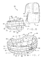
FIGS. 9-12 , in some embodiments, thereceiver component 314 may include abase portion 321 having alocking mechanism 322 for mechanically engaging and disengaging thereceiver component 314 from theadapter component 316. As shown inFIGS. 8 and 9 , thelocking mechanism 322 includes aretention arm 338 that cooperates with a rotatablebiased arm 336. Theretention arm 338 and the rotatablebiased arm 336 are operable to mechanically engage and disengage theadapter component 316 relative to thereceiver component 314. In particular, the rotatablebiased arm 336 is operative to rotate between an open position (FIG. 16 ) in which theadapter component 316 may be allowed to engage or disengage relative to thereceiver component 314 and a closed position (FIG. 17 ) in which theadapter component 316 is secured to thereceiver component 314. In some embodiments, the engagement and disengagement of theuniversal adapter system 300 is a "click-in" or "click-out" operation to engage or disengage theadapter component 316 from thereceiver component 314 in either a hands-free or one handed operation by the individual wearing thebase belt 303 as shall be discussed in greater detail below. - As shown in
FIGS. 10-12 , thebase portion 321 of thereceiver component 314 defines amiddle arm 325 having afirst side arm 327 defined on one side of themiddle arm 325 and asecond side arm 329 defined on an opposite side of themiddle arm 325 that collectively form anupper portion 339 and alower portion 341 of thereceiver component 314. In some embodiments, thelower portion 341 of themiddle arm 325 includes a first mountingmember 361 and an opposite second mountingmember 363 that each define a respective channel configured to receive respective ends of a bar 335 (FIGS. 9 and10 ), which allows the rotatablebiased arm 336 to rotate about thebar 335 at pivot point 386 (FIG. 10 ) such that the rotatablebiased arm 336 may rotate between the open and closed positions described above. As shown inFIG. 9 , arecess 355 is formed between the first mountingmember 361 and the second mountingmember 363 of themiddle arm 325 and defines a first plurality ofopenings 359 that are arranged to be aligned with a second plurality ofopenings 357 formed along aplate 353 secured behind themiddle portion 325 of thebase portion 321 for receiving securingmembers 356 that secure theplate 353 behind therecess 355. In this arrangement, theretention arm 338 extends outwardly from theplate 353 and through thebase portion 321 in a fixed position relative to the rotatablebiased arm 336 as illustrated inFIG. 10 . - As shown in
FIGS. 7 ,10 and 11 , in some embodiments thefirst side arm 327 may define alower retention portion 397 and anupper retention portion 398, while thesecond side arm 329 also defines alower retention portion 399 and anupper retention portion 387, which are each configured to engagerespective channels 320 defined along one or more ofwebbing portions 308 to secure thereceiver component 314 to thebase belt 303. In some embodiments, thebase portion 321 of thereceiver component 314 may define any combination of lower andupper retention portions receiver component 314 to thebase belt 303. In some embodiments as shown inFIG. 10 , thereceiver component 314 may include aretainer portion 388 that defines an arm forming aslot 383 to couple thereceiver component 314 to anupper edge 396 of thebase belt 303 as shown inFIG. 7 . - As further shown in
FIGS. 8-11 and 17 the rotatablebiased arm 336 forms a first raisedportion 380 and a second raisedportion 382 that collectively form achannel 324 configured to receive the mountingbar 310 of theadapter component 316 therein when securing thereceiver component 314 to theadapter component 316 as specifically shown inFIGS. 8 and17 . As illustrated inFIG. 9 , apassage 390 is formed through first raisedportion 380 and communicates with and is in perpendicular orientation relative to thechannel 324 defined by the rotatablebiased arm 336. Thepassage 390 is configured to permit theretention arm 338 to extend outwardly through the first raisedportion 380 to block access to thechannel 324, thereby preventing the mountingbar 310 from disengaging from thechannel 324 of the rotatablebiased arm 336 when thelocking mechanism 322 is in the closed position (FIGS. 8 and17 ). - As further shown in
FIGS. 8, 9 and11 , thereceiver component 314 includes aspring 315 that applies a bias to the rotatablebiased arm 336 in direction A (FIG. 16 ) to bias the rotatablebiased arm 336 to a normally-closed position (FIG. 17 ) such that theretention arm 338 extends outwardly through thepassage 390 to block access with thechannel 324 of the rotatablebiased arm 336. When theadapter component 316 is engaged to thereceiver component 314, the mountingmember 310 of theadapter component 316 is prevented from disengagement from the rotatablebiased arm 336 by theretention arm 338. Conversely, as shown inFIG. 16 rotation of the rotatablebiased arm 336 in direction B moves the rotatablebiased arm 336 from the closed position (FIG. 17 ) to the open position (FIG. 16 ) such that theretention arm 338 becomes recessed within thepassage 390 and no longer blocks thechannel 324, thereby allowing the mountingbar 310 to be disengaged from the rotatablebiased arm 336. - Referring to
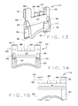
FIGS. 13-15 , in some embodiments theadapter component 316 may include a mountingbody 326 configured to be mounted to webbing sections of the backpack 301 (FIGS. 1 and6 ). The mountingbody 326 defines afront surface 347 and arear surface 348 that collectively form afirst arm portion 350, asecond arm portion 352, afirst leg portion 354 and asecond leg portion 356. In addition, thefront surface 347 defines first andsecond sockets rod 310. - As shown in
FIG. 13 , thefirst arm portion 350 of the mountingbody 326 defines aslot 370, while thesecond arm portion 352 defines aslot 372 which are configured to engage theadapter component 316 to theload bearing pack 301. In addition, first andsecond tab portions body 326 and in parallel orientation relative to the first andsecond arm portions FIGS. 13-15 . As shown inFIG. 7 , the first andsecond tab portions backpack 301 when securing theadapter component 316 to thebackpack 301. Referring toFIG. 13 , thefirst leg portion 354 may define atang 362 at the free end thereof, while thesecond leg portion 356 may define atang 364 at the thereof in which thetangs backpack 301. - In some embodiments, the
universal adapter systems universal adapter system 300 as an example, as shown inFIG. 18 the rotatablebiased arm 336 may be in contact between the first and second ends 392 and 393 of thecurved portion 391 of the mountingbar 310 when there is no shift in load, such as when the individual is stationary and/or in a substantially upright position. As illustrated inFIG. 19 , movement of the individual in a particular direction and/or the individual assuming a particular body position that causes a shift in load may be compensated byadapter component 316 through a sliding action of the mountingbar 310 in direction C along thechannel 324 of thelocking mechanism 322. As illustrated inFIG. 20 , movement of the individual in an opposite direction or the individual assuming another body position that causes a shift in load that may also be compensated through a sliding action of the mountingbar 310 in an opposite direction D along thechannel 324 of thelocking mechanism 322. In this manner, any shift in load that occurs is compensated through sliding action of the mountingbar 310 along thechannel 324 of thereceiver component 314. In addition to a sliding action that compensates for any shift in load when the individual assumes a different body position, the mountingbar 310 may also move in a twisting action relative to channel 324. In some embodiments, the twisting and/or sliding actions of the mountingbar 310 may also result in the mountingbar 310 becoming disengaged from thechannel 324 of the rotatablebiased arm 336 of thereceiver component 314. For example, a sliding action between theadapter component 316 and thereceiver component 314 where either the first or second ends 392 and 393 of the mountingbar 310 contacts thechannel 324 can cause the mountingbar 310 to disengage from the rotatablebiased arm 336. This same disengagement feature also applies touniversal adapter systems - In one aspect of the
universal adapter systems adapter components 116, 216, 316 from therespective receiver components respective base belts backpacks respective base belts universal adapter systems adapter components 116, 216, 316 from therespective receiver components respective base belts backpacks respective base belts - In some embodiments, the
universal adapter systems universal adapter systems universal adapter systems - It should be understood from the foregoing that, while particular embodiments have been illustrated and described, various modifications can be made thereto without departing from the spirit and scope of the invention as will be apparent to those skilled in the art. Such changes and modifications are within the scope and teachings of this invention as defined in the claims appended hereto.
- Some embodiments of the invention are illustrated by the following clauses:
- 1. A universal adapter system comprising:
- a receiver component comprising:
- a base portion configured to be coupled to a base belt and
- a locking mechanism secured to the base portion, the locking mechanism comprising a rotatable biased arm defining a channel and a retention arm in operative association with the rotatable biased arm, wherein the locking mechanism is rotatable between an open position that allows access to the channel by the retention arm and a closed position that blocks access to the channel by the retention arm; and
- an adapter component that is operative to be secured to the receiver component, the adapter component comprising:
- a mounting body configured to be coupled to a load bearing pack that compensates for shifting of a load associated with an individual; and
- a mounting bar extending from the mounting body and configured to be received within the channel of the rotatable biased arm, wherein a shift in load caused by the load bearing pack associated with movement of an individual generates a sliding action by the mounting bar relative to the rotatable biased arm.
- a receiver component comprising:
- 2. The universal adapter system of clause 1, wherein the load bearing pack comprises a backpack.
- 3. The universal adapter system of clause 1 or clause 2, wherein the mounting body of the adapter component comprises a first arm portion defining a first slot and a second arm portion defining a second slot configured for engaging the adapter component to the load bearing pack.
- 4. The universal adapter system of any preceding clause, wherein the mounting body of the adapter component comprises at least one tab portion configured for engaging the adapter component to the load bearing pack.
- 5. The universal adapter system of any preceding clause, wherein the mounting bar comprises a curved middle portion defined between a first end and a second end of the mounting bar that collectively extend axially outward relative to the mounting body.
- 6. The universal adapter system of clause 5, wherein the curved middle portion of the mounting bar is mechanically coupled to the locking mechanism of the receiver component such that the mounting bar is capable of a sliding action along the channel of the rotatable biased arm in response to the shift in load.
- 7. The universal adapter system of any preceding clause, wherein the rotatable biased arm comprises a first raised portion and a second raised portion that collectively define the channel, wherein the first raised portion defines a passage in perpendicular relation to the channel and configured to allow the retention arm to pass through when the locking mechanism is in the closed position.
- 8. The universal adapter system of any preceding clause, wherein the locking mechanism comprises a spring in operative engagement with the rotatable biased arm, wherein the spring applies a bias to maintain the rotatable biased arm in the closed position.
- 9. The universal adapter system of any preceding clause, wherein the rotatable biased arm comprises a rod member that secures the rotatable biased arm to the base portion such that the rotatable biased arm rotates about a pivot point defined by the rod member between the open and closed positions of the locking mechanism.
- 10. The universal adapter system of any preceding clause, wherein the base portion of the receiver component is configured to engage a base belt that includes at least one webbing portion, base portion defines a middle arm defined between a first side arm and a second side arm, wherein the first side arm and the second side arm define at least one retention portion configured to engage the at least one portion.
- 11. The universal adapter system of any preceding clause, wherein the retention arm is in a fixed position relative to the base portion of the receiver component when the locking mechanism is in either the open or closed positions.
- 12. The universal adapter system of any preceding clause, wherein the closed position the retention arm extends through a passage defined by the rotatable biased arm and blocks access to the channel when the locking mechanism is in the closed position.
- 13. The universal adapter system of any preceding clause, wherein base portion of the receiver component defines a middle arm defined between a first side arm and a second side arm.
- 14. The universal adapter system of any preceding clause, wherein the base portion is configured to receive a plate secured thereto, wherein the retention arm extends outwardly from the plate and through the base portion.
- 15. The universal adapter system of any preceding clause, wherein a shift in load caused by the load bearing pack generates a twisting action by the mounting bar relative to the rotatable biased arm.
- 16. A universal adapter system comprising:
- a receiver component comprising:
- a base portion configured to be coupled to a base belt; and
- a locking mechanism secured to the base portion, the locking mechanism comprising a rotatable biased arm defining a channel and a retention arm in operative association with the rotatable biased arm, wherein the locking mechanism is rotatable between an open position that allows access to the channel by the retention arm and a closed position that blocks access to the channel by the retention arm; and
- an adapter component that is operative to be coupled to the receiver component, the adapter component comprising:
- a mounting body secured to a load bearing pack; and
- a mounting bar extending from the mounting body and configured to be received within the channel of the rotatable biased arm, wherein a shift in load associated with an individual causes a sliding action by the mounting bar along the channel of the locking mechanism to compensate for a shifting of the load of the load bearing pack associated with movement of the individual.
- a receiver component comprising:
- 17. The universal adapter system of clause 13 or 16, wherein a shift in load caused the load bearing pack generates a twisting action by the mounting bar relative to the rotatable biased arm.
- 18. A method of assembling a universal adapter system comprising:
- coupling a receiver component to a base belt configured to be worn around the waist of an individual, the receiver component comprising:
- a base portion configured to be coupled to the base belt and
- a locking mechanism secured to the base portion, the locking mechanism comprising a rotatable biased arm defining a channel and a retention arm in operative association with the rotatable biased arm, wherein the locking mechanism is rotatable between an open position that allows access to the channel by the retention arm and a closed position that blocks access to the channel by the retention arm;
- placing the locking mechanism of the receiver component in the open position;
- engaging an adapter component to the locking mechanism of the receiver component, the adapter component comprising:
- a mounting body configured to be coupled to a load bearing pack; and
- a mounting bar extending from the mounting body, the mounting bar being configured to be received within the channel of rotatable biased arm, wherein a shift in load caused by the load bearing pack generates a sliding action by the mounting bar along the channel of the locking mechanism to compensate for a shifting of the load associated with movement of the individual; and
- placing the locking mechanism of the receiver component in the closed position.
- coupling a receiver component to a base belt configured to be worn around the waist of an individual, the receiver component comprising:
- 19. The method of clause 18, further comprising:
- coupling the mounting body of the adapter component to the load bearing pack.
- 20. The method of clause 18 or clause 19, wherein the load bearing pack is a backpack.
Claims (15)
- A universal adapter system comprising:a receiver component comprising:a base portion configured to be coupled to a base belt anda locking mechanism secured to the base portion, the locking mechanism comprising a rotatable biased arm defining a channel and a retention arm in operative association with the rotatable biased arm, wherein the locking mechanism is rotatable between an open position that allows access to the channel by the retention arm and a closed position that blocks access to the channel by the retention arm; andan adapter component that is operative to be secured to the receiver component, the adapter component comprising: a mounting body configured to be coupled to a load bearing pack that compensates for shifting of a load associated with an individual; anda mounting bar extending from the mounting body and configured to be received within the channel of the rotatable biased arm, wherein a shift in load caused by the load bearing pack associated with movement of an individual generates a sliding action by the mounting bar relative to the rotatable biased arm.
- The universal adapter system of claim 1, wherein the load bearing pack comprises a backpack.
- The universal adapter system of claim 1 or claim 2, wherein the mounting body of the adapter component comprises a first arm portion defining a first slot and a second arm portion defining a second slot configured for engaging the adapter component to the load bearing pack.
- The universal adapter system of any preceding claim, wherein the mounting body of the adapter component comprises at least one tab portion configured for engaging the adapter component to the load bearing pack.
- The universal adapter system of any preceding claim, wherein the mounting bar comprises a curved middle portion defined between a first end and a second end of the mounting bar that collectively extend axially outward relative to the mounting body.
- The universal adapter system of claim 5, wherein the curved middle portion of the mounting bar is mechanically coupled to the locking mechanism of the receiver component such that the mounting bar is capable of a sliding action along the channel of the rotatable biased arm in response to the shift in load.
- The universal adapter system of any preceding claim, wherein the rotatable biased arm comprises a first raised portion and a second raised portion that collectively define the channel, wherein the first raised portion defines a passage in perpendicular relation to the channel and configured to allow the retention arm to pass through when the locking mechanism is in the closed position.
- The universal adapter system of any preceding claim, wherein the locking mechanism comprises a spring in operative engagement with the rotatable biased arm, wherein the spring applies a bias to maintain the rotatable biased arm in the closed position.
- The universal adapter system of any preceding claim, wherein the rotatable biased arm comprises a rod member that secures the rotatable biased arm to the base portion such that the rotatable biased arm rotates about a pivot point defined by the rod member between the open and closed positions of the locking mechanism.
- The universal adapter system of any preceding claim, wherein the base portion of the receiver component is configured to engage a base belt that includes at least one webbing portion, base portion defines a middle arm defined between a first side arm and a second side arm, wherein the first side arm and the second side arm define at least one retention portion configured to engage the at least one portion.
- The universal adapter system of any preceding claim, wherein the retention arm is in a fixed position relative to the base portion of the receiver component when the locking mechanism is in either the open or closed positions.
- The universal adapter system of any preceding claim, wherein the closed position the retention arm extends through a passage defined by the rotatable biased arm and blocks access to the channel when the locking mechanism is in the closed position.
- A method of assembling a universal adapter system comprising:coupling a receiver component to a base belt configured to be worn around the waist of an individual, the receiver component comprising:a base portion configured to be coupled to the base belt anda locking mechanism secured to the base portion, the locking mechanism comprising a rotatable biased arm defining a channel and a retention arm in operative association with the rotatable biased arm, wherein the locking mechanism is rotatable between an open position that allows access to the channel by the retention arm and a closed position that blocks access to the channel by the retention arm;placing the locking mechanism of the receiver component in the open position;engaging an adapter component to the locking mechanism of the receiver component, the adapter component comprising:a mounting body configured to be coupled to a load bearing pack; anda mounting bar extending from the mounting body, the mounting bar being configured to be received within the channel of rotatable biased arm, wherein a shift in load caused by the load bearing pack generates a sliding action by the mounting bar along the channel of the locking mechanism to compensate for a shifting of the load associated with movement of the individual; andplacing the locking mechanism of the receiver component in the closed position.
- The method of claim 13, further comprising:coupling the mounting body of the adapter component to the load bearing pack.
- The method of claim 13 or claim 14, wherein the load bearing pack is a backpack.
Applications Claiming Priority (1)
| Application Number | Priority Date | Filing Date | Title |
|---|---|---|---|
| US201461992116P | 2014-05-12 | 2014-05-12 |
Publications (2)
| Publication Number | Publication Date |
|---|---|
| EP2944221A1 true EP2944221A1 (en) | 2015-11-18 |
| EP2944221B1 EP2944221B1 (en) | 2019-10-09 |
Family
ID=53719598
Family Applications (3)
| Application Number | Title | Priority Date | Filing Date |
|---|---|---|---|
| EP15167421.5A Active EP2944221B1 (en) | 2014-05-12 | 2015-05-12 | Universal adapter system for load bearing packs |
| EP15167420.7A Active EP2944220B1 (en) | 2014-05-12 | 2015-05-12 | Universal adapter system for a dynamic load carriage apparatus |
| EP18214725.6A Active EP3539415B1 (en) | 2014-05-12 | 2015-05-12 | Universal adapter system for a dynamic load carriage apparatus |
Family Applications After (2)
| Application Number | Title | Priority Date | Filing Date |
|---|---|---|---|
| EP15167420.7A Active EP2944220B1 (en) | 2014-05-12 | 2015-05-12 | Universal adapter system for a dynamic load carriage apparatus |
| EP18214725.6A Active EP3539415B1 (en) | 2014-05-12 | 2015-05-12 | Universal adapter system for a dynamic load carriage apparatus |
Country Status (5)
| Country | Link |
|---|---|
| US (4) | US9820555B2 (en) |
| EP (3) | EP2944221B1 (en) |
| AU (2) | AU2015202529B2 (en) |
| CA (2) | CA2890955C (en) |
| DK (3) | DK2944220T3 (en) |
Cited By (1)
| Publication number | Priority date | Publication date | Assignee | Title |
|---|---|---|---|---|
| JP5969684B1 (en) * | 2015-12-02 | 2016-08-17 | 恵子 儀間 | Backpack for school bag |
Families Citing this family (9)
| Publication number | Priority date | Publication date | Assignee | Title |
|---|---|---|---|---|
| AU2015202529B2 (en) * | 2014-05-12 | 2019-11-28 | Tyr Tactical, Llc | Universal adapter system for load bearing packs |
| NO3040988T3 (en) * | 2014-10-24 | 2018-03-24 | ||
| GB2563864B (en) * | 2017-06-27 | 2022-01-12 | Draeger Safety Uk Ltd | Harness for breathing apparatus |
| ES2895698T3 (en) * | 2017-09-27 | 2022-02-22 | Globe Jiangsu Co Ltd | Pivoting carrier assembly for a harness |
| US10842243B2 (en) * | 2017-12-15 | 2020-11-24 | Pantelis Chatzidakis | Weight support systems |
| EP3622849B1 (en) * | 2018-09-17 | 2022-11-02 | Andreas Stihl AG & Co. KG | Back-held carrying device, in particular for a battery pack |
| CN113027716B (en) * | 2021-04-08 | 2022-05-17 | 南京邮电大学 | Travelling speed self-adaptive power generation backpack |
| WO2023102616A1 (en) * | 2021-12-10 | 2023-06-15 | Emil Saad Andrawos | A backpack aid |
| CN115890633B (en) * | 2023-01-10 | 2023-05-12 | 中科携行(北京)科技有限公司 | Quick-wearing and taking-off bionic exoskeleton back frame |
Citations (4)
| Publication number | Priority date | Publication date | Assignee | Title |
|---|---|---|---|---|
| WO1998020772A1 (en) * | 1996-11-14 | 1998-05-22 | Down East, Inc. | Belt assembly to support and release a backpack |
| US5806741A (en) * | 1997-09-16 | 1998-09-15 | The United States Of America As Represented By The Secretary Of The Army | Load-carrying system |
| US6321959B1 (en) * | 1998-08-13 | 2001-11-27 | Down East, Inc. | Low profile socket for backpack |
| US7337935B1 (en) * | 2003-06-09 | 2008-03-04 | Glanville James J | Golf bag coupling system |
Family Cites Families (12)
| Publication number | Priority date | Publication date | Assignee | Title |
|---|---|---|---|---|
| US5201858A (en) * | 1992-08-07 | 1993-04-13 | Otrusina Edward C | Quick-release connector |
| US5609278A (en) * | 1994-11-18 | 1997-03-11 | Fresco; Andre | Articulated backpack apparatus |
| US5604958A (en) * | 1995-11-06 | 1997-02-25 | National Molding Corp. | Attachment system for backpacks, vests, belts and the like |
| US5622296A (en) * | 1995-12-06 | 1997-04-22 | Pirhonen; Ilkka | Releasable swivel holder for personal articles |
| US5954250A (en) * | 1996-05-31 | 1999-09-21 | Draeger Limited | Harnesses |
| US5730342A (en) * | 1997-04-11 | 1998-03-24 | Tien; Tse-Hsiung | Mobile telephone fastening |
| TW409043B (en) * | 1998-12-24 | 2000-10-21 | Ykk Corp | Buckle |
| DE102009042455B4 (en) * | 2009-09-23 | 2016-03-17 | Hexonia Gmbh | Support system with a ballistic protective vest |
| US8857681B2 (en) * | 2012-03-08 | 2014-10-14 | The United States Of America As Represented By The Secretary Of The Air Force | Load carriage connector and system |
| NL2008784C2 (en) * | 2012-05-09 | 2013-11-12 | Toto Carrying Systems B V | Load carrying system. |
| US9220333B2 (en) * | 2013-11-27 | 2015-12-29 | Msa Technology, Llc | Adjustable lumbar support for mounting on a backpack and backpack having the same |
| AU2015202529B2 (en) * | 2014-05-12 | 2019-11-28 | Tyr Tactical, Llc | Universal adapter system for load bearing packs |
-
2015
- 2015-05-11 AU AU2015202529A patent/AU2015202529B2/en active Active
- 2015-05-11 US US14/708,381 patent/US9820555B2/en active Active
- 2015-05-11 AU AU2015202531A patent/AU2015202531B2/en active Active
- 2015-05-11 CA CA2890955A patent/CA2890955C/en active Active
- 2015-05-11 US US14/708,398 patent/US10028570B2/en active Active
- 2015-05-11 CA CA2890959A patent/CA2890959C/en active Active
- 2015-05-12 DK DK15167420.7T patent/DK2944220T3/en active
- 2015-05-12 DK DK18214725.6T patent/DK3539415T3/en active
- 2015-05-12 EP EP15167421.5A patent/EP2944221B1/en active Active
- 2015-05-12 EP EP15167420.7A patent/EP2944220B1/en active Active
- 2015-05-12 DK DK15167421.5T patent/DK2944221T3/en active
- 2015-05-12 EP EP18214725.6A patent/EP3539415B1/en active Active
-
2018
- 2018-07-17 US US16/038,036 patent/US10568407B2/en active Active
-
2020
- 2020-02-24 US US16/799,261 patent/US11064793B2/en active Active
Patent Citations (4)
| Publication number | Priority date | Publication date | Assignee | Title |
|---|---|---|---|---|
| WO1998020772A1 (en) * | 1996-11-14 | 1998-05-22 | Down East, Inc. | Belt assembly to support and release a backpack |
| US5806741A (en) * | 1997-09-16 | 1998-09-15 | The United States Of America As Represented By The Secretary Of The Army | Load-carrying system |
| US6321959B1 (en) * | 1998-08-13 | 2001-11-27 | Down East, Inc. | Low profile socket for backpack |
| US7337935B1 (en) * | 2003-06-09 | 2008-03-04 | Glanville James J | Golf bag coupling system |
Cited By (1)
| Publication number | Priority date | Publication date | Assignee | Title |
|---|---|---|---|---|
| JP5969684B1 (en) * | 2015-12-02 | 2016-08-17 | 恵子 儀間 | Backpack for school bag |
Also Published As
| Publication number | Publication date |
|---|---|
| DK2944220T3 (en) | 2019-05-13 |
| EP3539415A1 (en) | 2019-09-18 |
| US20180338603A1 (en) | 2018-11-29 |
| CA2890955A1 (en) | 2015-11-12 |
| CA2890959C (en) | 2020-07-07 |
| US20150320182A1 (en) | 2015-11-12 |
| US11064793B2 (en) | 2021-07-20 |
| AU2015202529B2 (en) | 2019-11-28 |
| AU2015202531A1 (en) | 2015-11-26 |
| EP2944220A1 (en) | 2015-11-18 |
| US10028570B2 (en) | 2018-07-24 |
| US20150320150A1 (en) | 2015-11-12 |
| EP2944220B1 (en) | 2019-04-03 |
| CA2890959A1 (en) | 2015-11-12 |
| EP2944221B1 (en) | 2019-10-09 |
| DK2944221T3 (en) | 2020-01-20 |
| DK3539415T3 (en) | 2021-02-15 |
| US20200205555A1 (en) | 2020-07-02 |
| AU2015202531B2 (en) | 2019-11-21 |
| CA2890955C (en) | 2020-07-14 |
| US9820555B2 (en) | 2017-11-21 |
| US10568407B2 (en) | 2020-02-25 |
| EP3539415B1 (en) | 2020-11-11 |
| AU2015202529A1 (en) | 2015-11-26 |
Similar Documents
| Publication | Publication Date | Title |
|---|---|---|
| EP2944221B1 (en) | Universal adapter system for load bearing packs | |
| US10850940B2 (en) | Retracting device for mounting to a web strap | |
| EP2281170B1 (en) | Adjustable, detachable accessory attachment system | |
| US20190274415A1 (en) | Pouch or holster coupled with a retracting device | |
| US4214686A (en) | Keeper for load carrying equipment | |
| EP4011240B1 (en) | Molle adapter | |
| EP3048930B1 (en) | Gear track system | |
| EP3091871B1 (en) | Belt mounting system | |
| US11156436B2 (en) | Dynamic load carriage system | |
| CA2936781A1 (en) | Tactical belt | |
| US20140090145A1 (en) | Flexible Mid-Section Float System for Protective Outerwear | |
| TWI689393B (en) | Sheath with attachment system | |
| US20210071987A1 (en) | Molle/pals attachment system | |
| US20170097217A1 (en) | Belt adaptor for mounting accessories | |
| US20170284767A1 (en) | Wearable weapon support assembly | |
| US20230341211A1 (en) | Interchangeable, multi location, multi cant, auto locking, quick mount for holsters, handheld devices, and carried gear | |
| US20110036880A1 (en) | Clip system for use with belt | |
| AU2016213715A1 (en) | Tactical belt |
Legal Events
| Date | Code | Title | Description |
|---|---|---|---|
| PUAI | Public reference made under article 153(3) epc to a published international application that has entered the european phase |
Free format text: ORIGINAL CODE: 0009012 |
|
| AK | Designated contracting states |
Kind code of ref document: A1 Designated state(s): AL AT BE BG CH CY CZ DE DK EE ES FI FR GB GR HR HU IE IS IT LI LT LU LV MC MK MT NL NO PL PT RO RS SE SI SK SM TR |
|
| AX | Request for extension of the european patent |
Extension state: BA ME |
|
| 17P | Request for examination filed |
Effective date: 20160517 |
|
| RBV | Designated contracting states (corrected) |
Designated state(s): AL AT BE BG CH CY CZ DE DK EE ES FI FR GB GR HR HU IE IS IT LI LT LU LV MC MK MT NL NO PL PT RO RS SE SI SK SM TR |
|
| R17P | Request for examination filed (corrected) |
Effective date: 20160517 |
|
| RAP1 | Party data changed (applicant data changed or rights of an application transferred) |
Owner name: TYR TACTICAL, LLC |
|
| STAA | Information on the status of an ep patent application or granted ep patent |
Free format text: STATUS: EXAMINATION IS IN PROGRESS |
|
| 17Q | First examination report despatched |
Effective date: 20180817 |
|
| REG | Reference to a national code |
Ref country code: DE Ref legal event code: R079 Ref document number: 602015039358 Country of ref document: DE Free format text: PREVIOUS MAIN CLASS: A45F0003060000 Ipc: A45F0003040000 |
|
| RIC1 | Information provided on ipc code assigned before grant |
Ipc: A45F 3/14 20060101ALI20190228BHEP Ipc: A45F 3/04 20060101AFI20190228BHEP Ipc: A45F 3/06 20060101ALI20190228BHEP |
|
| GRAP | Despatch of communication of intention to grant a patent |
Free format text: ORIGINAL CODE: EPIDOSNIGR1 |
|
| STAA | Information on the status of an ep patent application or granted ep patent |
Free format text: STATUS: GRANT OF PATENT IS INTENDED |
|
| INTG | Intention to grant announced |
Effective date: 20190417 |
|
| GRAS | Grant fee paid |
Free format text: ORIGINAL CODE: EPIDOSNIGR3 |
|
| GRAA | (expected) grant |
Free format text: ORIGINAL CODE: 0009210 |
|
| STAA | Information on the status of an ep patent application or granted ep patent |
Free format text: STATUS: THE PATENT HAS BEEN GRANTED |
|
| RIN1 | Information on inventor provided before grant (corrected) |
Inventor name: BECK, JASON |
|
| AK | Designated contracting states |
Kind code of ref document: B1 Designated state(s): AL AT BE BG CH CY CZ DE DK EE ES FI FR GB GR HR HU IE IS IT LI LT LU LV MC MK MT NL NO PL PT RO RS SE SI SK SM TR |
|
| REG | Reference to a national code |
Ref country code: GB Ref legal event code: FG4D |
|
| REG | Reference to a national code |
Ref country code: CH Ref legal event code: EP |
|
| REG | Reference to a national code |
Ref country code: IE Ref legal event code: FG4D |
|
| REG | Reference to a national code |
Ref country code: DE Ref legal event code: R096 Ref document number: 602015039358 Country of ref document: DE |
|
| REG | Reference to a national code |
Ref country code: AT Ref legal event code: REF Ref document number: 1187774 Country of ref document: AT Kind code of ref document: T Effective date: 20191115 |
|
| REG | Reference to a national code |
Ref country code: NO Ref legal event code: T2 Effective date: 20191009 |
|
| REG | Reference to a national code |
Ref country code: NL Ref legal event code: FP |
|
| REG | Reference to a national code |
Ref country code: DK Ref legal event code: T3 Effective date: 20200114 |
|
| REG | Reference to a national code |
Ref country code: LT Ref legal event code: MG4D |
|
| REG | Reference to a national code |
Ref country code: AT Ref legal event code: MK05 Ref document number: 1187774 Country of ref document: AT Kind code of ref document: T Effective date: 20191009 |
|
| PG25 | Lapsed in a contracting state [announced via postgrant information from national office to epo] |
Ref country code: BG Free format text: LAPSE BECAUSE OF FAILURE TO SUBMIT A TRANSLATION OF THE DESCRIPTION OR TO PAY THE FEE WITHIN THE PRESCRIBED TIME-LIMIT Effective date: 20200109 Ref country code: FI Free format text: LAPSE BECAUSE OF FAILURE TO SUBMIT A TRANSLATION OF THE DESCRIPTION OR TO PAY THE FEE WITHIN THE PRESCRIBED TIME-LIMIT Effective date: 20191009 Ref country code: PL Free format text: LAPSE BECAUSE OF FAILURE TO SUBMIT A TRANSLATION OF THE DESCRIPTION OR TO PAY THE FEE WITHIN THE PRESCRIBED TIME-LIMIT Effective date: 20191009 Ref country code: AT Free format text: LAPSE BECAUSE OF FAILURE TO SUBMIT A TRANSLATION OF THE DESCRIPTION OR TO PAY THE FEE WITHIN THE PRESCRIBED TIME-LIMIT Effective date: 20191009 Ref country code: LT Free format text: LAPSE BECAUSE OF FAILURE TO SUBMIT A TRANSLATION OF THE DESCRIPTION OR TO PAY THE FEE WITHIN THE PRESCRIBED TIME-LIMIT Effective date: 20191009 Ref country code: PT Free format text: LAPSE BECAUSE OF FAILURE TO SUBMIT A TRANSLATION OF THE DESCRIPTION OR TO PAY THE FEE WITHIN THE PRESCRIBED TIME-LIMIT Effective date: 20200210 Ref country code: ES Free format text: LAPSE BECAUSE OF FAILURE TO SUBMIT A TRANSLATION OF THE DESCRIPTION OR TO PAY THE FEE WITHIN THE PRESCRIBED TIME-LIMIT Effective date: 20191009 Ref country code: GR Free format text: LAPSE BECAUSE OF FAILURE TO SUBMIT A TRANSLATION OF THE DESCRIPTION OR TO PAY THE FEE WITHIN THE PRESCRIBED TIME-LIMIT Effective date: 20200110 Ref country code: SE Free format text: LAPSE BECAUSE OF FAILURE TO SUBMIT A TRANSLATION OF THE DESCRIPTION OR TO PAY THE FEE WITHIN THE PRESCRIBED TIME-LIMIT Effective date: 20191009 Ref country code: LV Free format text: LAPSE BECAUSE OF FAILURE TO SUBMIT A TRANSLATION OF THE DESCRIPTION OR TO PAY THE FEE WITHIN THE PRESCRIBED TIME-LIMIT Effective date: 20191009 |
|
| PG25 | Lapsed in a contracting state [announced via postgrant information from national office to epo] |
Ref country code: RS Free format text: LAPSE BECAUSE OF FAILURE TO SUBMIT A TRANSLATION OF THE DESCRIPTION OR TO PAY THE FEE WITHIN THE PRESCRIBED TIME-LIMIT Effective date: 20191009 Ref country code: HR Free format text: LAPSE BECAUSE OF FAILURE TO SUBMIT A TRANSLATION OF THE DESCRIPTION OR TO PAY THE FEE WITHIN THE PRESCRIBED TIME-LIMIT Effective date: 20191009 Ref country code: IS Free format text: LAPSE BECAUSE OF FAILURE TO SUBMIT A TRANSLATION OF THE DESCRIPTION OR TO PAY THE FEE WITHIN THE PRESCRIBED TIME-LIMIT Effective date: 20200224 |
|
| PG25 | Lapsed in a contracting state [announced via postgrant information from national office to epo] |
Ref country code: AL Free format text: LAPSE BECAUSE OF FAILURE TO SUBMIT A TRANSLATION OF THE DESCRIPTION OR TO PAY THE FEE WITHIN THE PRESCRIBED TIME-LIMIT Effective date: 20191009 |
|
| REG | Reference to a national code |
Ref country code: DE Ref legal event code: R097 Ref document number: 602015039358 Country of ref document: DE |
|
| PG2D | Information on lapse in contracting state deleted |
Ref country code: IS |
|
| PG25 | Lapsed in a contracting state [announced via postgrant information from national office to epo] |
Ref country code: CZ Free format text: LAPSE BECAUSE OF FAILURE TO SUBMIT A TRANSLATION OF THE DESCRIPTION OR TO PAY THE FEE WITHIN THE PRESCRIBED TIME-LIMIT Effective date: 20191009 Ref country code: RO Free format text: LAPSE BECAUSE OF FAILURE TO SUBMIT A TRANSLATION OF THE DESCRIPTION OR TO PAY THE FEE WITHIN THE PRESCRIBED TIME-LIMIT Effective date: 20191009 Ref country code: EE Free format text: LAPSE BECAUSE OF FAILURE TO SUBMIT A TRANSLATION OF THE DESCRIPTION OR TO PAY THE FEE WITHIN THE PRESCRIBED TIME-LIMIT Effective date: 20191009 Ref country code: IS Free format text: LAPSE BECAUSE OF FAILURE TO SUBMIT A TRANSLATION OF THE DESCRIPTION OR TO PAY THE FEE WITHIN THE PRESCRIBED TIME-LIMIT Effective date: 20200209 |
|
| PLBE | No opposition filed within time limit |
Free format text: ORIGINAL CODE: 0009261 |
|
| STAA | Information on the status of an ep patent application or granted ep patent |
Free format text: STATUS: NO OPPOSITION FILED WITHIN TIME LIMIT |
|
| PG25 | Lapsed in a contracting state [announced via postgrant information from national office to epo] |
Ref country code: SK Free format text: LAPSE BECAUSE OF FAILURE TO SUBMIT A TRANSLATION OF THE DESCRIPTION OR TO PAY THE FEE WITHIN THE PRESCRIBED TIME-LIMIT Effective date: 20191009 Ref country code: SM Free format text: LAPSE BECAUSE OF FAILURE TO SUBMIT A TRANSLATION OF THE DESCRIPTION OR TO PAY THE FEE WITHIN THE PRESCRIBED TIME-LIMIT Effective date: 20191009 Ref country code: IT Free format text: LAPSE BECAUSE OF FAILURE TO SUBMIT A TRANSLATION OF THE DESCRIPTION OR TO PAY THE FEE WITHIN THE PRESCRIBED TIME-LIMIT Effective date: 20191009 |
|
| 26N | No opposition filed |
Effective date: 20200710 |
|
| PG25 | Lapsed in a contracting state [announced via postgrant information from national office to epo] |
Ref country code: SI Free format text: LAPSE BECAUSE OF FAILURE TO SUBMIT A TRANSLATION OF THE DESCRIPTION OR TO PAY THE FEE WITHIN THE PRESCRIBED TIME-LIMIT Effective date: 20191009 |
|
| PG25 | Lapsed in a contracting state [announced via postgrant information from national office to epo] |
Ref country code: MC Free format text: LAPSE BECAUSE OF FAILURE TO SUBMIT A TRANSLATION OF THE DESCRIPTION OR TO PAY THE FEE WITHIN THE PRESCRIBED TIME-LIMIT Effective date: 20191009 Ref country code: LI Free format text: LAPSE BECAUSE OF NON-PAYMENT OF DUE FEES Effective date: 20200531 Ref country code: CH Free format text: LAPSE BECAUSE OF NON-PAYMENT OF DUE FEES Effective date: 20200531 |
|
| REG | Reference to a national code |
Ref country code: BE Ref legal event code: MM Effective date: 20200531 |
|
| PG25 | Lapsed in a contracting state [announced via postgrant information from national office to epo] |
Ref country code: LU Free format text: LAPSE BECAUSE OF NON-PAYMENT OF DUE FEES Effective date: 20200512 |
|
| PG25 | Lapsed in a contracting state [announced via postgrant information from national office to epo] |
Ref country code: IE Free format text: LAPSE BECAUSE OF NON-PAYMENT OF DUE FEES Effective date: 20200512 |
|
| PG25 | Lapsed in a contracting state [announced via postgrant information from national office to epo] |
Ref country code: BE Free format text: LAPSE BECAUSE OF NON-PAYMENT OF DUE FEES Effective date: 20200531 |
|
| PG25 | Lapsed in a contracting state [announced via postgrant information from national office to epo] |
Ref country code: TR Free format text: LAPSE BECAUSE OF FAILURE TO SUBMIT A TRANSLATION OF THE DESCRIPTION OR TO PAY THE FEE WITHIN THE PRESCRIBED TIME-LIMIT Effective date: 20191009 Ref country code: MT Free format text: LAPSE BECAUSE OF FAILURE TO SUBMIT A TRANSLATION OF THE DESCRIPTION OR TO PAY THE FEE WITHIN THE PRESCRIBED TIME-LIMIT Effective date: 20191009 Ref country code: CY Free format text: LAPSE BECAUSE OF FAILURE TO SUBMIT A TRANSLATION OF THE DESCRIPTION OR TO PAY THE FEE WITHIN THE PRESCRIBED TIME-LIMIT Effective date: 20191009 |
|
| PG25 | Lapsed in a contracting state [announced via postgrant information from national office to epo] |
Ref country code: MK Free format text: LAPSE BECAUSE OF FAILURE TO SUBMIT A TRANSLATION OF THE DESCRIPTION OR TO PAY THE FEE WITHIN THE PRESCRIBED TIME-LIMIT Effective date: 20191009 |
|
| PGFP | Annual fee paid to national office [announced via postgrant information from national office to epo] |
Ref country code: GB Payment date: 20230307 Year of fee payment: 9 |
|
| PGFP | Annual fee paid to national office [announced via postgrant information from national office to epo] |
Ref country code: NO Payment date: 20230504 Year of fee payment: 9 Ref country code: NL Payment date: 20230510 Year of fee payment: 9 Ref country code: FR Payment date: 20230508 Year of fee payment: 9 Ref country code: DK Payment date: 20230509 Year of fee payment: 9 Ref country code: DE Payment date: 20230508 Year of fee payment: 9 |