EP2911237A1 - Receiver assembly - Google Patents
Receiver assembly Download PDFInfo
- Publication number
- EP2911237A1 EP2911237A1 EP15152618.3A EP15152618A EP2911237A1 EP 2911237 A1 EP2911237 A1 EP 2911237A1 EP 15152618 A EP15152618 A EP 15152618A EP 2911237 A1 EP2911237 A1 EP 2911237A1
- Authority
- EP
- European Patent Office
- Prior art keywords
- mast
- receiver
- arm
- bracket
- pivot pin
- Prior art date
- Legal status (The legal status is an assumption and is not a legal conclusion. Google has not performed a legal analysis and makes no representation as to the accuracy of the status listed.)
- Granted
Links
- 230000033001 locomotion Effects 0.000 claims description 14
- 239000000463 material Substances 0.000 description 7
- 230000007246 mechanism Effects 0.000 description 6
- 238000000034 method Methods 0.000 description 6
- 239000002689 soil Substances 0.000 description 6
- 230000000712 assembly Effects 0.000 description 5
- 238000000429 assembly Methods 0.000 description 5
- 238000010276 construction Methods 0.000 description 4
- 230000000694 effects Effects 0.000 description 3
- 238000009434 installation Methods 0.000 description 3
- VNWKTOKETHGBQD-UHFFFAOYSA-N methane Chemical compound C VNWKTOKETHGBQD-UHFFFAOYSA-N 0.000 description 2
- 238000005065 mining Methods 0.000 description 2
- 230000005540 biological transmission Effects 0.000 description 1
- 238000005219 brazing Methods 0.000 description 1
- 230000004048 modification Effects 0.000 description 1
- 238000012986 modification Methods 0.000 description 1
- 239000003345 natural gas Substances 0.000 description 1
- 230000000737 periodic effect Effects 0.000 description 1
- 230000002787 reinforcement Effects 0.000 description 1
- 238000009877 rendering Methods 0.000 description 1
- 238000003466 welding Methods 0.000 description 1
Images


Classifications
-
- G—PHYSICS
- G01—MEASURING; TESTING
- G01S—RADIO DIRECTION-FINDING; RADIO NAVIGATION; DETERMINING DISTANCE OR VELOCITY BY USE OF RADIO WAVES; LOCATING OR PRESENCE-DETECTING BY USE OF THE REFLECTION OR RERADIATION OF RADIO WAVES; ANALOGOUS ARRANGEMENTS USING OTHER WAVES
- G01S19/00—Satellite radio beacon positioning systems; Determining position, velocity or attitude using signals transmitted by such systems
- G01S19/01—Satellite radio beacon positioning systems transmitting time-stamped messages, e.g. GPS [Global Positioning System], GLONASS [Global Orbiting Navigation Satellite System] or GALILEO
- G01S19/13—Receivers
- G01S19/35—Constructional details or hardware or software details of the signal processing chain
-
- H—ELECTRICITY
- H01—ELECTRIC ELEMENTS
- H01Q—ANTENNAS, i.e. RADIO AERIALS
- H01Q1/00—Details of, or arrangements associated with, antennas
- H01Q1/12—Supports; Mounting means
- H01Q1/1235—Collapsible supports; Means for erecting a rigid antenna
-
- F—MECHANICAL ENGINEERING; LIGHTING; HEATING; WEAPONS; BLASTING
- F16—ENGINEERING ELEMENTS AND UNITS; GENERAL MEASURES FOR PRODUCING AND MAINTAINING EFFECTIVE FUNCTIONING OF MACHINES OR INSTALLATIONS; THERMAL INSULATION IN GENERAL
- F16B—DEVICES FOR FASTENING OR SECURING CONSTRUCTIONAL ELEMENTS OR MACHINE PARTS TOGETHER, e.g. NAILS, BOLTS, CIRCLIPS, CLAMPS, CLIPS OR WEDGES; JOINTS OR JOINTING
- F16B19/00—Bolts without screw-thread; Pins, including deformable elements; Rivets
-
- G—PHYSICS
- G01—MEASURING; TESTING
- G01S—RADIO DIRECTION-FINDING; RADIO NAVIGATION; DETERMINING DISTANCE OR VELOCITY BY USE OF RADIO WAVES; LOCATING OR PRESENCE-DETECTING BY USE OF THE REFLECTION OR RERADIATION OF RADIO WAVES; ANALOGOUS ARRANGEMENTS USING OTHER WAVES
- G01S19/00—Satellite radio beacon positioning systems; Determining position, velocity or attitude using signals transmitted by such systems
- G01S19/01—Satellite radio beacon positioning systems transmitting time-stamped messages, e.g. GPS [Global Positioning System], GLONASS [Global Orbiting Navigation Satellite System] or GALILEO
- G01S19/13—Receivers
- G01S19/14—Receivers specially adapted for specific applications
-
- H—ELECTRICITY
- H01—ELECTRIC ELEMENTS
- H01Q—ANTENNAS, i.e. RADIO AERIALS
- H01Q1/00—Details of, or arrangements associated with, antennas
- H01Q1/12—Supports; Mounting means
- H01Q1/22—Supports; Mounting means by structural association with other equipment or articles
-
- H—ELECTRICITY
- H01—ELECTRIC ELEMENTS
- H01Q—ANTENNAS, i.e. RADIO AERIALS
- H01Q1/00—Details of, or arrangements associated with, antennas
- H01Q1/27—Adaptation for use in or on movable bodies
- H01Q1/32—Adaptation for use in or on road or rail vehicles
- H01Q1/3208—Adaptation for use in or on road or rail vehicles characterised by the application wherein the antenna is used
- H01Q1/3233—Adaptation for use in or on road or rail vehicles characterised by the application wherein the antenna is used particular used as part of a sensor or in a security system, e.g. for automotive radar, navigation systems
-
- H—ELECTRICITY
- H01—ELECTRIC ELEMENTS
- H01Q—ANTENNAS, i.e. RADIO AERIALS
- H01Q1/00—Details of, or arrangements associated with, antennas
- H01Q1/27—Adaptation for use in or on movable bodies
- H01Q1/32—Adaptation for use in or on road or rail vehicles
- H01Q1/325—Adaptation for use in or on road or rail vehicles characterised by the location of the antenna on the vehicle
- H01Q1/3275—Adaptation for use in or on road or rail vehicles characterised by the location of the antenna on the vehicle mounted on a horizontal surface of the vehicle, e.g. on roof, hood, trunk
-
- B—PERFORMING OPERATIONS; TRANSPORTING
- B60—VEHICLES IN GENERAL
- B60R—VEHICLES, VEHICLE FITTINGS, OR VEHICLE PARTS, NOT OTHERWISE PROVIDED FOR
- B60R11/00—Arrangements for holding or mounting articles, not otherwise provided for
- B60R2011/0001—Arrangements for holding or mounting articles, not otherwise provided for characterised by position
- B60R2011/004—Arrangements for holding or mounting articles, not otherwise provided for characterised by position outside the vehicle
-
- Y—GENERAL TAGGING OF NEW TECHNOLOGICAL DEVELOPMENTS; GENERAL TAGGING OF CROSS-SECTIONAL TECHNOLOGIES SPANNING OVER SEVERAL SECTIONS OF THE IPC; TECHNICAL SUBJECTS COVERED BY FORMER USPC CROSS-REFERENCE ART COLLECTIONS [XRACs] AND DIGESTS
- Y10—TECHNICAL SUBJECTS COVERED BY FORMER USPC
- Y10T—TECHNICAL SUBJECTS COVERED BY FORMER US CLASSIFICATION
- Y10T29/00—Metal working
- Y10T29/49—Method of mechanical manufacture
- Y10T29/49826—Assembling or joining
- Y10T29/4984—Retaining clearance for motion between assembled parts
Abstract
Description
- The present disclosure relates to a receiver assembly, and more specifically to a receiver assembly for a machine.
- Construction machines such as tractors, graders, soil compactors and other machines may typically employ one or more receivers to perform diagnostic or other auxiliary functions during operation of the machine. The receivers may be, for example, GPS receivers to provide geographical information pertaining to a location of the machine. Typically, such receivers are mounted onto the machine at a considerable height from the ground surface. Conventional mounting systems used to mount the receivers onto the machine may include, for example, a long pole or shaft one end of which may be affixed to the machine while another end may hold the receiver.
- In some cases, the receivers may have to be periodically removed and re-installed after operation of the machine to perform service routines thereon or for preventing theft of the receivers. However, in such cases, the operating or service personnel may find it cumbersome to install or remove the receivers with use of the conventional mounting systems.
- In one aspect of the present disclosure, a receiver assembly is provided for a machine. The receiver assembly includes a bracket, a mast, and a receiver. The bracket includes a base disposed on the machine, at least one arm extending from the base, and a pivot pin disposed on the arm. The mast is disposed alongside the arm and pivotally supported on the pivot pin. The receiver is releasably engaged to the mast and is pivotable together with the mast about the pivot pin.
- In another aspect of the present disclosure, a machine includes a frame, an implement connected to the frame and configured to operate on a ground surface, and a receiver assembly disposed on the implement. The receiver assembly includes a bracket, a mast, and a receiver. The bracket includes a base disposed on the implement. The bracket further includes at least one arm extending from the base, and a pivot pin disposed on the arm. The mast is disposed alongside the arm and pivotally supported on the pivot pin. The receiver is releasably engaged to the mast and is pivotable together with the mast about the pivot pin.
- Other features and aspects of this disclosure will be apparent from the following description and the accompanying drawings.
-
-
Figure 1 is a side view of an exemplary machine employing a receiver assembly in accordance with an embodiment of the present disclosure; -
Figure 2 is a diagrammatic representation of the receiver assembly in an assembled state and an exploded state; -
Figure 3 is a perspective view of the receiver assembly showing a stop plate and various components thereon; -
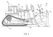
Figure 4 is a diagrammatic representation of the receiver assembly in use by an operator of the machine; -
Figure 5 is a diagrammatic representation of the receiver assembly having a one-arm configuration; -
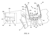
Figure 6 is a perspective view of the receiver assembly in accordance with a modified embodiment of the present disclosure; -
Figure 7 is an assembled view of the modified receiver assembly fromFigure 6 showing a working of the modified receiver assembly; -
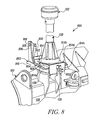
Figure 8 is a rear perspective view of the receiver assembly in accordance with another embodiment of the present disclosure; -
Figure 9 is a front perspective view of the receiver assembly ofFigure 8 ; -
Figure 10 is an exemplary diagrammatic representation of a fastening mechanism employed between the bracket and the mast in accordance with an embodiment of the present disclosure; -
Figure 11 is an exemplary diagrammatic view of the machine employing receiver assemblies in accordance with various embodiments of the present disclosure; and -
Figure 12 is a perspective view of yet another modified embodiment of the receiver assembly. - The present disclosure relates to a receiver assembly for a machine. Wherever possible the same reference numbers will be used throughout the drawings to refer to same or like parts.
Figure 1 illustrates anexemplary machine 100 according to one aspect of the present disclosure. As illustrated, themachine 100 may embody a track-type tractor (TTT). The track-type tractor (TTT) disclosed herein may be an elevated sprocket TTT (as shown) or may optionally embody an oval drive TTT. - Alternatively, the
machine 100 may be, for example, a snowplow, a backhoe loader, a skid steer loader, a wheel loader, a motor grader, a soil compactor and the like. Although a track-type tractor (TTT), a backhoe loader, a skid steer loader, a wheel loader, and a motor grader are disclosed herein, it may be noted that themachine 100 may be any wheeled or tracked vehicle employed in mining, agriculture, forestry, construction, shipping, and other industrial applications. - As illustrated in
Figure 1 , theexemplary machine 100 includes aframe 102. Further, theexemplary machine 100 may include apower source 104, and one or more groundengaging elements 106 mounted on theframe 102. The groundengaging elements 106 may be operatively coupled to thepower source 104 by a transmission system such as a gearbox (not shown) and/or a propulsion system such as axles (not shown). Thepower source 104 may be configured to drive the groundengaging elements 106 during operation of themachine 100 such that themachine 100 is propelled on aground surface 108. - The
power source 104, disclosed herein, may include, for example, a diesel engine, a gasoline engine, a natural gas engine or any other type of engine commonly known in the art. The groundengaging elements 106 may be a pair of tracks (one track shown on one side of the machine 100). However, in alternative embodiments, the groundengaging elements 106 may be embodied as wheels. - The
machine 100 further includes animplement 110 pivotally connected to theframe 102. Theimplement 110 is configured to operate on theground surface 108. As illustrated inFigure 1 , theimplement 110 may embody a blade. For purposes of ease and clarity in understanding the present disclosure, the term "implement" will hereinafter be referred to as "the blade" and will be designated with thesame numeral 110. - Although explanation to the present disclosure is hereinafter made with reference to the
blade 110, it is to be noted that structures and methods of the present disclosure are equally applicable to other types of implements commonly known in the art. Other exemplary implements that may be used in lieu of theblade 110 may include, but is not limited to, excavating buckets, loading buckets, soil compacting drums, snow-pushers, or soil tillers. Therefore, a scope of the term "implement" is not limited to theblade 110 disclosed herein, rather the scope may extend to include other types of implements commonly known in the art. A person having ordinary skill in the art will hence, acknowledge that a type of the implement disclosed herein is merely exemplary in nature and hence, non-limiting of this disclosure. - With reference to the specific embodiment of
Figure 1 , theblade 110 may include afront face 112 and a rear face 114 (shown inFigure 2 ). Thefront face 112 of theblade 110 may be configured to interface with earth materials on theground surface 108 when themachine 100 is propelled in the forward direction "A". Accordingly, thefront face 112 of theblade 110 may perform functions of moving, collecting, or transporting the earth materials on theground surface 108. The earth materials, disclosed herein, may include oil, debris, snow, or ice, but is not limited thereto. - Referring to
Figure 1 , themachine 100 further includes areceiver assembly 116 disposed on the implement i.e. theblade 110. Although it is disclosed herein that thereceiver assembly 116 is disposed on theblade 110, it should be noted that in other embodiments of the present disclosure, thereceiver assembly 116 could be suitably located at any location of themachine 100 depending on the specific machine type and/or specific requirements of an application. For example, if themachine 100 is a soil compactor, thereceiver assembly 116 may be located on a cab or a frame of the soil compactor. - Explanation pertaining to the
receiver assembly 116 will now be made in conjunction withFigures 2-5 . Referring toFigure 2 , tworeceiver assemblies 116 are shown in an assembled and exploded state respectively. Thereceiver assembly 116 includes abracket 118, amast 120, and areceiver 122. Thebracket 118 includes abase 124 horizontally disposed on the implement i.e.blade 110. - In an embodiment as shown in
Figure 2 , thebase 124 may be disposed horizontally on amounting pad 126 of theblade 110. The mountingpad 126 protrudes laterally from therear face 114 of theblade 110 and provides a surface area for mounting of the base 124 thereon. The base 124 may be releasably attached to themounting pad 126 by one ormore fasteners 128. Thefasteners 128 disclosed herein, may include, for example, setscrews, Allen screws, grub screws, hex bolts, rivets or any other type of fastener commonly known in the art to accomplish a releasable attachment between two components. - The
bracket 118 further includes at least onearm 130 upstanding from the base 124 (twoarms 130 shown upstanding from eachbracket 118 inFigure 2 ). Thebracket 118 further includes apivot pin 132 transversely disposed on thearm 130. In an embodiment as shown inFigure 2 , thepivot pin 132 may be inserted through co-axially locatedapertures 134 defined by therespective arms 130 of thebracket 118. Thepivot pin 132 may extend, at least in part, outwardly from thearms 130 and one or both ends 138 of thepivot pin 132 may be provided with connector elements (not shown) for releasably securing thepivot pin 132 to thearms 130. With regards to the present disclosure, it is contemplated that thepivot pin 132 may be disposed in stationary relationship with thearms 130 and provides a substantially frictionless outer surface thereon. - Optionally, the
arms 130 and/or thepivot pin 132 may be provided with respective interfitting or interlocking mechanisms (not shown) to accomplish the releasable securement of thepivot pin 132 to thearms 130. Accordingly, it is to be understood that a type of connector element is merely exemplary in nature and hence, non-limiting of this disclosure. The connector element, interfitting mechanism, or interlocking mechanism, disclosed herein, may include, for example, position retainers such as, but not limited to, wedges, keys, splines or other structures commonly known to a person ordinarily skilled in the art. - The
mast 120 is disposed alongside thearm 130 and pivotally supported on thepivot pin 132. As shown inFigure 2 , the twoarms 130 are axially spaced apart along axis Z-Z' to receive themast 120 therebetween. Themast 120 may define alateral opening 140 disposed in axial alignment with theapertures 134 of thearms 130. Thelateral opening 140 may be suitably sized and shaped to receive thepivot pin 132 therethrough. In an embodiment of the present disclosure, thelateral opening 140, disclosed herein, may be additionally provided with a bearing surface (not shown), for example, a journal, or a roller bearing press-fit therein, to help facilitate a smooth pivotal motion of themast 120 about thepivot pin 132. Although onelateral opening 140 is described herein, themast 120 may be optionally provided with multiple lateral openings 140 (as shown), explanation to which will be made later in this document. - The
receiver 122 is releasably engaged to themast 120 and is pivotable together with themast 120 about thepivot pin 132. As shown in the exemplary embodiment ofFigure 2 , thereceiver 122 is releasably engaged to atop end 142 of themast 120. The releasable engagement between thereceiver 122 and themast 120 may be accomplished bysuitable interfitting structures 144 disposed on themast 120 and thereceiver 122. Theinterfitting structures 144 may include bolts, screws, clamps, catches, holders, customized fixtures, or jigs, but is not limited thereto. Although someinterfitting structures 144 are disclosed herein, it is to be noted that many suitable structures are commonly known in the art and may be implemented to form theinterfitting structures 144 disclosed herein without deviating from the scope and spirit of the present disclosure. A person having ordinary skill in the art will therefore acknowledge that a type of interfitting structures employed to accomplish the aforesaid releasable engagement is merely exemplary in nature and non-limiting of this disclosure. - The
receiver 122, disclosed herein, may be of a type configured to execute mainstream functions in themachine 100. However, in alternative embodiments, thereceiver 122 may be of a type configured to perform support and/or auxiliary and/or diagnostic functions such as, but not limited to, collecting, recording, storing, transmitting, or receiving data pertaining to operation of themachine 100 on theground surface 108. In one embodiment, thereceiver 122 may be a Global Positioning System (GPS)receiver 122 configured to provide geographical information pertaining to a location of themachine 100. - In another embodiment, the
receiver 122 may be a Universal Target System (UTS) configured to provide data pertaining to a profile, contour or elevation of the ground surface 108 (referring toFigure 1 ). In an alternative embodiment, thereceiver 122 may be a laser catcher configured to provide articulation data of the implement 110. Although theGPS receiver 122, the UTS, and the laser catcher are disclosed herein, a type ofreceiver 122 used in themachine 100 is merely exemplary in nature and non-limiting of this disclosure. Anysuitable receiver 122 may be employed by themachine 100 depending on specific requirements of an application and/or machine type. - As shown in
Figure 2 , thereceiver assembly 116 may further include a lockingassembly 146 located on thearm 130 and disposed in an axially offset relation to thepivot pin 132. The lockingassembly 146 may be operable to lock themast 120 in an upright position. Additionally, the lockingassembly 146 may be operable to release themast 120 from the upright position and thereafter allow themast 120 to be pivoted about thepivot pin 132. - In the specific embodiment of
Figure 2 , the lockingassembly 146 may include one ormore holes 148 defined in therespective arms 130 of thebracket 118, and alocking pin 150 slidably received therethrough. Thelocking pin 150 may be substantially elongated such that when thelocking pin 150 is inserted through the hole, the lockingpin 150 extends at least partway between thearms 130 to retain themast 120 in the upright position. However, upon removal of thelocking pin 150 from the hole of thearm 130, themast 120 may be rendered pivotable about thepivot pin 132. Although, the lockingassembly 146 disclosed herein is implemented by way of theholes 148 and thelocking pin 150, it is to be noted that other implementations of the lockingassembly 146 are also possible and will be explained later in this document. - Turning to
Figure 3 , in an embodiment of the present disclosure, thearm 130 of thebracket 118 may preferably extend at least partway beyond a mid-portion 152 of themast 120 and thepivot pin 132 may be located proximate to anupper end 154 of thearm 130. The aforesaid arrangement may allow a weight of thereceiver 122 and theupper portion 156 of themast 120 to be counterbalanced by a weight of alower portion 158 of themast 120. Moreover, if themast 120 includes multiplelateral openings 140 along themid-portion 152 thereof, then an effective height of the mast 120 (i.e. height of themast 120 located outward of the bracket 118) can be suitably adjusted to obtain a desired counterbalance effect between the upper andlower portions mast 120. Thus, themast 120 may be prevented from inadvertently swinging or pivoting about thepivot pin 132 and causing thereceiver 122 to rapidly fall forward of theblade 110. - In an embodiment of the present disclosure, the
bracket 118 may further include astop plate 160 located adjacent to thebase 124 and thearm 130. In an exemplary embodiment as shown inFigure 3 , thestop plate 160 may extend partway along thebase 124 and affix with thearms 130 of thebracket 118. Thestop plate 160 may prevent a continuous pivotal motion of themast 120 about thepivot pin 132. Further, thestop plate 160 may be additionally configured to prevent earth materials and/or other objects such as dirt, ice, or muck from entering thebracket 118 from operation of the blade 110 (SeeFigure 1 ). As shown inFigure 1 , earth materials and/or other objects encountered at thefront face 112 of theblade 110 during operation of themachine 100 may be prevented by thestop plate 160 from entering onto atop face 162 of thebase 124. Consequently, thestop plate 160 may prevent the earth materials and/or other objects from settling onto thetop face 162 of thebase 124 and obstructing a positioning of themast 120 above thebase 124. - With continued reference to
Figure 3 , in an embodiment of the present disclosure, the top surface of thebase 124 and abottom end 164 of themast 120 may be configured to define a clearance 166 therebetween. Beneficially, the top surface of thebase 124 and thebottom end 164 of themast 120 may be sloped downward, i.e. in the direction of pivoting of themast 120, to facilitate free movement of themast 120 relative to thebase 124. Therefore, aslanted parting line 168 together with the clearance 166 may prevent any interference between thebottom end 164 of themast 120 and the top surface of the base 124 during pivotal movement of themast 120. - With reference to various embodiments of the present disclosure, although two
arms 130 are disclosed as being part of thebracket 118, the present disclosure may be equally implemented with just onearm 130, or with more than onearm 130 as set forth in the claims. In an exemplary embodiment as shown inFigure 5 , asingle arm 130 may be disposed on the base 124 while thepivot pin 132 may laterally extend from thearm 130 to pivotally support themast 120. -
Figures 6 and7 illustrate a modified embodiment of areceiver assembly 600. Referring toFigure 6 , thereceiver assembly 600 includes afirst bracket 618 having a fixedbase 624 and twoarms 630a and 630b upstanding from the fixedbase 624. The fixedbase 624 is configured to rigidly affix with the mountingpad 126 of theblade 110. As shown, the fixedbase 624 can be releasably coupled to themounting pad 126 with the help offasteners 128. However, other structures and methods of fastening commonly known in the art may be suitably employed in lieu of thefasteners 128. - The
receiver assembly 600 further includes asecond bracket 620 pivotally connected to thefirst bracket 618. As shown in the embodiment ofFigures 6 and7 , thesecond bracket 620 can include apivotable base 625 having a pair ofarms 631a and 631b upstanding therefrom. Thearms 631a and 631b of thesecond bracket 620 can be disposed between thearms 630a and 630b of thefirst bracket 618. Moreover, thearm 631 a may be pivotally coupled to thearm 630a with the help ofpivot pin 632a while the arm 631b may be pivotally coupled to the arm 630b via pivot pin 632b. The pivot pins 632a and 632b can therefore allow relative movement of thesecond bracket 620 with respect to thefirst bracket 618. Further, thefirst bracket 618 may optionally include astop plate 660 located adjacent to the fixedbase 624 and thearms 630a and 630b. Thestop plate 660 serves to prevent pivotal motion of thesecond bracket 620 upon contact therewith. - Furthermore, a
bottom side 646 of thepivotable base 625 includes one ormore ribs 656 extending therefrom. Theribs 656 may be provided for structural reinforcement of thesecond bracket 620. Theseribs 656 are disposed facing atop surface 662 of the fixedbase 624. Theribs 656 and thetop surface 662 of the fixedbase 624 can be beneficially sloped downward, i.e., in the direction of pivoting of thesecond bracket 620, to define aslanted parting line 668 therebetween and to facilitate free movement of thesecond bracket 620 relative to thefirst bracket 618. Therefore, upon assembly of thesecond bracket 620 and thefirst bracket 618, theslanted parting line 668 may prevent any interference between theribs 656 and the fixedbase 624 during pivotal movement of thesecond bracket 620 with respect to thefirst bracket 618. - Moreover, embodiments of the locking
assembly 146 described herein may be equally implemented in or applied to the one-arm configuration of the bracket 118 (as shown inFigure 5 ) or with thebrackets Figures 6-9 . For the sake of brevity in this document, it to be noted that a working of thereceiver assembly 116 may be similarly related to, and applied in understanding a working of thereceiver assembly 600. Accordingly, it is an aspect of the present disclosure that various configurations of thebracket 118 and/or themast 120 may be suitably modified to accomplish pivoting of themast 120 and thereceiver 122 thereabout and to lower thereceiver 122 preferably, forward of the blade 110 (i.e. towards the front face 112) without deviating from the scope of the present disclosure. References, if any, to specific numbers, shapes, sizes, and configurations of components in thereceiver assembly - Moreover, although various components of the
bracket 118 are described herein as being separate from each other and coupled using various mechanisms, it is also possible to have the components of thebracket 118 integrally formed with each other in order to impart a unitary and/or robust construction to thebracket 118. -
Figure 8 shows another embodiment of areceiver assembly 800. As shown in this embodiment, thereceiver assembly 800 can include afirst bracket 802 and asecond bracket 804. Thefirst bracket 802 can include a fixedbase 806 releasably fastened to themounting pad 126 of the implement 110. Thefirst bracket 802 can include a pair ofarms 806 extending from the fixed base (only one arm visible in this view). Thearms 806 may extend partway along a side 808 of the fixedbase 806. Moreover, thearms 806, as shown inFigures 8 and9 , are disposed only on aforward portion 810 of the fixedbase 806 and formed in combination with thestop plate 812. This configuration of thearms 806 can beneficially reduce material costs required to form thearms 806 while also rendering thearms 806 with adequate strength to pivotally support thesecond bracket 804 and themast 120 thereon. - The
second bracket 804 includes apivotable base 814 andarms 816 extending from thepivotable base 814. Thearms 816 of thesecond bracket 804 are disposed alongside and correspond to thearms 806 of thefirst bracket 802. Thearms 816 of thesecond bracket 804 can be coupled to thearms 806 of thefirst bracket 802 with the help of pivot pins 818. - In an embodiment as shown in
Figure 8 , thereceiver assembly 800 can additionally include one ormore retaining cylinders 820 disposed between thefirst bracket 802 and thesecond bracket 804. The retainingcylinders 820 can be pivotally coupled to thearms second brackets second bracket 804 relative to thefirst bracket 802. Moreover, the retainingcylinders 820 can beneficially offset forces that may be encountered by the pivot pins 818 from movement of thesecond bracket 804 relative to thefirst bracket 802. - Turning back to
Figure 8 , thepivotable base 814 has a first portion 814a, and asecond portion 814b that is angled away from the first portion 814a. The first portion 814a is angled such that it abuts the fixedbase 806 of thefirst bracket 802 when themast 120 is in the upright position. Thesecond portion 814b can be used to fasten themast 120 thereon. Thesecond portion 814b has atab 814c angularly extending from anend 814d thereof. - In an embodiment of the present disclosure, the
receiver assembly 800 can include a lockingassembly 822 disposed on thetab 814c of thepivotable base 814. As depicted inFigure 8 , the lockingassembly 822 is a spring-loaded latch that is operable between a latched and unlatched position. When the spring-loaded latch is in the latched position, it may prevent relative movement of thesecond bracket 804 with respect to thefirst bracket 802, while in the unlatched position; the spring-loaded latch may allow an operator to pivot thesecond bracket 804 about the pivot pins 818 and/or about the retainingcylinders 820. Although a spring-loaded latch is disclosed herein, other structures can be suitably implemented to form the locking assemblies 146 (seeFigure 2 ), or 822 of the present disclosure. Some examples of such structures may include clamps, bolts, catch plates, spring-loaded lock-pins, or snap-fitting arrangements, but are not limited thereto. Therefore, reference to specific types and/or configurations of thelocking assemblies locking assemblies - Referring to
Figure 10 , thereceiver assembly 800 can include afastening mechanism 824 to releasably fasten themast 120 onto thesecond bracket 804. Accordingly, as shown, thesecond bracket 804 may be suitably modified to include an interconnectingmember 826 disposed between thearms second bracket 804. In an embodiment as shown inFigure 10 , the interconnectingmember 826 may be an arcuate plate formed integrally with thepivotable base 814 and thearms member 826 may be joined to thepivotable base 814 and therespective arms - The
receiver assembly 800 can further include a pair oflegs 828 depending downwardly from thelower portion 158 of themast 120. Theselegs 828 may be coupled to the interconnectingmember 826 with the help of apin 830 to accomplish a pivotal connection between themast 120 and thepivotable base 814. The pivotal connection established by thepin 830 between themast 120 and thepivotable base 814 may allow pivoting of themast 120 in a plane different from that offered by the pivot pins 818 located between the first andsecond brackets - As shown in
Figure 11 , the pivot pins 818 between the first andsecond brackets mast 120 in the Y-Y plane, while thepin 830 between the interconnectingmember 826 of thesecond bracket 804 and thelegs 828 of themast 120 can allow the operator to pivot themast 120 in the X-X plane. Additionally, the receiver assembly can further include one ormore shackles 832 that are operable to selectively permit movement of themast 120 in the X-X plane. Specifically, theshackles 832 can be opened or closed by an operator to permit or restrict movement of themast 120 in the X-X plane. - With continued reference to
Figure 11 , tworeceivers 122 are shown in association with themasts 120 respectively. Thereceiver 122 associated with the mast 120 (depicted on left hand side ofFigure 11 ) may be a laser catcher while thereceiver 122 associated with the mast 120 (depicted on right hand side ofFigure 11 ) may be a GPS receiver. However, as disclosed earlier herein, thereceiver assembly 800 can include any type ofreceiver 122 therein depending on specific requirements of the machine. Moreover, various embodiments of thereceiver assembly 800 disclosed herein can be implemented onto a machine for mounting any known type of receiver without limiting a scope of the present disclosure. - Referring to
Figure 12 , another modified embodiment of thereceiver assembly 1200 is depicted. In this embodiment, thereceiver assembly 1200 can include afirst bracket 1202 having fourarms base 1206. The fourarms 1204 are grouped in pairs and located on either side of thefirst bracket 1202. Each of the fourarms 1204 includes ahole 1208 that is co-axially aligned withholes 1208 provided on theother arms 1204. - The
receiver assembly 1200 can further include asecond bracket 1210 having a pivotable base 1212 and fourarms arms 1214 are grouped in pairs and located on either side of thesecond bracket 1210. Thearms 1214 of thesecond bracket 1210 includeholes 1216 that correspond withholes 1208 on thearms 1204 of thefirst bracket 1202. Each grouped pair ofarms 1214 of thesecond bracket 1210 may be interspersed and alternately arranged with the pair ofarms 1204 of thefirst bracket 1202 such that theholes arms second brackets more pivot pins 1218 therethrough. It is to be noted that although twopivot pins 1218 are illustrated in the exemplary embodiment ofFigure 12 , any number ofpivot pins 1218 can be employed depending on the configuration of the first andsecond brackets - With reference to various embodiments of the present disclosure, it is to be noted that types, configurations, and/or numbers of specific components of the receiver assembly disclosed herein are merely exemplary in nature, and hence non-limiting of this disclosure. A person having ordinary skill in the art will appreciate that the receiver assembly can be formed with one or more structures removed, one or more structures added, or with one or more structures suitably modified or replaced with alternative structures without deviating from the scope of the claims appended herein.
- The
receiver assembly receiver assembly - The working of the
receiver assembly receiver 122 onto themachine 100, an operator or service personnel may stand on theground surface 108 and pivot themast 120 about the pivot pin 132 (seeFigure 4 ), thesecond bracket 620 about the pivot pins 632a and 632b (seeFigure 7 ), thesecond bracket 804 about the pivot pins 814 (seeFigure 8 ), or thesecond bracket 1210 about the pivot pins 1218 (seeFigure 12 ). Consequently, the operator may lower thereceiver 122, preferably forward of theblade 110 i.e. towards thefront face 112 of theblade 110. Thereafter, the operator may conveniently remove or re-install thereceiver 122 onto themast 120 since theupper end 154 of themast 120 and/or thereceiver 122 is now within the reach of the operator (SeeFigure 4 ). - Referring to
Figure 4 , the configurations and sizes of thebracket 118 and themast 120 together with the location of thepivot pin 132 from various embodiments disclosed herein may beneficially provide the desired counterbalance effect between the upper andlower portions mast 120. The counterbalance effect may prevent themast 120 from inadvertently swinging or pivoting about thepivot pin 132 and causing thereceiver 122 to rapidly fall forward of theblade 110. Therefore, the operator may have control of themast 120 and thereceiver 122 while turning or pivoting themast 120 about thepivot pin 132. - In cases such as, but not limited to, service routines of the
machine 100, or idle-time of themachine 100, the operator may quickly remove thereceiver 122 with use of the disclosed embodiments of thereceiver assembly receiver 122 onto themachine 100 before operation hours of themachine 100, the operator may quickly repeat the process as disclosed for removal but with steps for engaging thereceiver 122 to themast 120. It is evident from the present disclosure that the pivotal configuration of thereceiver assembly receiver 122 onto themachine 100. Consequently, implementation of thepresent receiver assembly 116 may reduce fatigue experienced by the personnel in performing frequent or periodic removal or installation of thereceiver 122 onto themachine 100. - Directional references (e.g. upper, lower, upward, downward, leftward, rightward, top, bottom, above, below, beside, upright, horizontal, clockwise, counter-clockwise), if present in this disclosure, is only used for identification purposes to aid the reader's understanding of the present disclosure, and may not create limitations, particularly as to the position, orientation, or use of the components and/or methods disclosed herein. Joinder references (e.g. attached, coupled, connected, hinged, affixed, engaged, and the like) are to be construed broadly and may include intermediate members between the disclosed components. As such, joinder references do not necessarily infer that two components are directly connected or are in fixed relation to each other.
- Similarly, adjectives and/or verbs, such as, but not limited to, "modified", "articulated", "pivotal" or similar, should be construed broadly and only as nominal, and may not create any limitations particularly as to the description, operation, or use unless specifically set forth in the claims.
- While aspects of the present disclosure have been particularly shown and described with reference to the embodiments above, it will be understood by those skilled in the art that various additional embodiments may be contemplated by the modification of the disclosed machines, systems and methods without departing from the spirit and scope of what is disclosed. Such embodiments should be understood to fall within the scope of the present disclosure as determined based upon the claims and any equivalents thereof.
Claims (15)
- A receiver assembly (116) for a machine (100), the receiver assembly (116) comprising:a bracket (118) comprising:a base (124) disposed on the machine (100);at least one arm (130) extending from the base (124);a pivot pin (132) disposed on the arm (130);a mast (120) disposed alongside the arm (130) and pivotally supported on the pivot pin (132); anda receiver (122) releasably engaged to the mast (120), wherein the receiver (122) together with the mast (120) is pivotable about the pivot pin (132).
- The receiver assembly (116) of claim 1, wherein the arm (130) extends at least partway beyond a mid-portion (152) of the mast (120).
- The receiver assembly (116) of claim 2, wherein the pivot pin (132) is proximate to an upper end (154) of the arm (130).
- The receiver assembly (116) of claim 1, wherein an upper portion (156) of the mast (120) is counterbalanced by a lower portion (158) of the mast (120).
- The receiver assembly (116) of claim 1 further including a locking assembly (146) located on the arm (130) and offset from the pivot pin (132), the locking assembly (146) operable to lock the mast (120) in an upright position.
- The receiver assembly (116) of claim 5, wherein the locking assembly (146) is further operable to pivot the mast (120) and the receiver (122) about the pivot pin (132).
- The receiver assembly (116) of claim 1, wherein the bracket (118) further includes a stop plate (160) located adjacent to the base (124) and the arm (130), the stop plate (160) configured to prevent a continuous pivotal motion of the mast (120) about the pivot pin (132).
- The receiver assembly (116) of claim 1, wherein a top surface of the base (124) and a bottom end (164) of the mast (120) together define a clearance (166) therebetween.
- The receiver assembly (116) of claim 1, wherein the receiver (122) is releasably engaged to a top end (142) of the mast (120).
- A machine (100) comprising:a frame;an implement connected to the frame, the implement configured to operate on a ground surface;a receiver assembly (116) disposed on the implement, the receiver assembly (116) comprising:a bracket (118) comprising:a base (124) disposed on the implement;at least one arm (130) extending from the base (124);a pivot pin (132) disposed on the arm (130);a mast (120) disposed alongside the arm (130) and pivotally supported on the pivot pin (132); anda receiver (122) releasably engaged to the mast (120),wherein the receiver (122) together with the mast (120) is pivotable about the pivot pin (132).
- The machine (100) of claim 10, wherein the arm (130) extends at least partway beyond a mid-portion (152) of the mast (120).
- The machine (100) of claim 10, wherein the receiver assembly (116) further includes a locking assembly (146) located on the arm (130) and offset from the pivot pin (132), the locking assembly (146) operable to lock the mast (120) in an upright position.
- The machine (100) of claim 10, wherein the bracket (118) further includes a stop plate (160) located adjacent to the base (124) and the arm (130), the stop plate (160) configured to limit a bi-directional rotation of the mast (120) about the pivot pin (132).
- The machine (100) of claim 10, wherein the receiver (122) is releasably engaged to a top end (142) of the mast (120).
- The machine (100) of claim 10, wherein the receiver (122) is at least one of a Global Positioning System (GPS) receiver, a Universal Target System (UTS), and a laser catcher.
Applications Claiming Priority (1)
| Application Number | Priority Date | Filing Date | Title |
|---|---|---|---|
| GB1403267.6A GB2523401B (en) | 2014-02-25 | 2014-02-25 | Receiver assembly |
Publications (2)
| Publication Number | Publication Date |
|---|---|
| EP2911237A1 true EP2911237A1 (en) | 2015-08-26 |
| EP2911237B1 EP2911237B1 (en) | 2023-04-19 |
Family
ID=50482743
Family Applications (1)
| Application Number | Title | Priority Date | Filing Date |
|---|---|---|---|
| EP15152618.3A Active EP2911237B1 (en) | 2014-02-25 | 2015-01-27 | Receiver assembly |
Country Status (4)
| Country | Link |
|---|---|
| US (1) | US20150244057A1 (en) |
| EP (1) | EP2911237B1 (en) |
| CN (1) | CN104868927A (en) |
| GB (1) | GB2523401B (en) |
Cited By (2)
| Publication number | Priority date | Publication date | Assignee | Title |
|---|---|---|---|---|
| GB2601988A (en) * | 2020-08-21 | 2022-06-22 | P Flannery Plant Hire Oval Ltd | Mount |
| EP4026412A4 (en) * | 2019-09-06 | 2023-10-11 | Kubota Corporation | Work vehicle |
Families Citing this family (2)
| Publication number | Priority date | Publication date | Assignee | Title |
|---|---|---|---|---|
| US10801178B2 (en) * | 2018-12-07 | 2020-10-13 | Deere & Company | Work tool attachment for a work machine |
| US11817616B2 (en) | 2021-04-12 | 2023-11-14 | Caterpillar Global Mining Equipment Llc | Antenna mast structure |
Citations (6)
| Publication number | Priority date | Publication date | Assignee | Title |
|---|---|---|---|---|
| WO1995019576A1 (en) * | 1994-01-14 | 1995-07-20 | Bicc Public Limited Company | Method and apparatus for positioning construction machinery |
| US6804587B1 (en) * | 2000-11-15 | 2004-10-12 | Integrinautics Corporation | Adjustment of vehicle-implement trajectories to compensate for lateral implement offset |
| US20050197756A1 (en) * | 1998-11-27 | 2005-09-08 | Taylor Arthur J. | Method and system for performing non-contact based determination of the position of an implement |
| US20060085118A1 (en) * | 2004-10-20 | 2006-04-20 | Leica Geosystems Ag | Method and apparatus for monitoring a load condition of a dragline |
| US20070255494A1 (en) * | 2006-04-27 | 2007-11-01 | Caterpillar Inc. | Boom-mounted machine locating system |
| US20080147282A1 (en) * | 2006-12-15 | 2008-06-19 | Georg Kormann | Tracking system configured to determine a parameter for use in guiding an implement attached to a work machine |
Family Cites Families (31)
| Publication number | Priority date | Publication date | Assignee | Title |
|---|---|---|---|---|
| US189514A (en) * | 1877-04-10 | Improvement in street and park lamps | ||
| US1971757A (en) * | 1933-08-08 | 1934-08-28 | Standard Oil Co | Flood lamp standard |
| US2667317A (en) * | 1949-08-04 | 1954-01-26 | Gabriel Co | Antenna mast support |
| US3224716A (en) * | 1961-12-28 | 1965-12-21 | Antenna Specialists Co | Collapsible antenna |
| FR2157044A5 (en) * | 1971-10-15 | 1973-06-01 | Eclairage Tech | |
| US3819136A (en) * | 1972-09-28 | 1974-06-25 | Allen Group | Marine antenna mount |
| US3886560A (en) * | 1974-05-31 | 1975-05-27 | Tandy Corp | Antenna swivel mount |
| US4266227A (en) * | 1979-08-20 | 1981-05-05 | Avanti Research & Development, Inc. | Mounting for mobile communications antenna |
| US5099251A (en) * | 1990-08-24 | 1992-03-24 | The Antenna Company | Evertight antenna mounting assembly |
| US5252985A (en) * | 1990-11-14 | 1993-10-12 | Christinsin Alan S | Whip tilt adapter |
| US5515064A (en) * | 1993-06-25 | 1996-05-07 | Allen Telecom Group, Inc. | Mobile communications antenna assembly |
| US5410325A (en) * | 1993-08-09 | 1995-04-25 | Caterpillar Inc. | Antenna mounting apparatus |
| US5449138A (en) * | 1993-12-23 | 1995-09-12 | Ciancio; Joseph | Convertible boom stand |
| FI943744A0 (en) * | 1994-08-15 | 1994-08-15 | Jouni Teodor Braks | Hopfaellbart staell Foer baerbar microdator i bil |
| US5506593A (en) * | 1995-02-17 | 1996-04-09 | Peng; Jung-Ching | Antenna protecting device for motor vehicles |
| US5459476A (en) * | 1995-02-17 | 1995-10-17 | Hsieh; Wu-Hsiung | Antenna protecting device for a motor vehicle |
| US5934694A (en) * | 1996-02-13 | 1999-08-10 | Dane Industries | Cart retriever vehicle |
| JP3031577U (en) * | 1996-05-22 | 1996-11-29 | 星野楽器株式会社 | Attachment / detachment structure of weight member in boom cymbal stand |
| JPH11129829A (en) * | 1997-10-31 | 1999-05-18 | Serustaa Kogyo Kk | On-vehicle article fixture |
| US6005518A (en) * | 1997-12-31 | 1999-12-21 | Kallina; Henry D. | Coaxial cable RF leakage detector |
| US6546677B1 (en) * | 2000-02-09 | 2003-04-15 | Featherstone Teamed Industries, Inc. | Telescoping mast assembly |
| US20080029669A1 (en) * | 2006-08-01 | 2008-02-07 | Rbw Industries, Inc. | Flat Screen TV Bracket For A Vehicle |
| USD593079S1 (en) * | 2008-04-25 | 2009-05-26 | The United States Of America As Represented By The Secretary Of The Army | Antenna tip-over mount |
| US8684373B2 (en) * | 2008-09-23 | 2014-04-01 | Dane Technologies, Inc. | Cart moving machine |
| US9139977B2 (en) * | 2010-01-12 | 2015-09-22 | Topcon Positioning Systems, Inc. | System and method for orienting an implement on a vehicle |
| US8272604B2 (en) * | 2010-03-24 | 2012-09-25 | Foster Gary D | Locking arm pedestal system |
| US8176832B1 (en) * | 2011-01-13 | 2012-05-15 | The United States Of America As Represented By The Secretary Of The Army | System and method for obstruction deflection |
| KR20120136475A (en) * | 2011-06-09 | 2012-12-20 | 전동욱 | Rest for hanging mobile communication terminals |
| US9130264B2 (en) * | 2012-05-09 | 2015-09-08 | Jeffrey Gervais | Apparatus for raising and lowering antennae |
| ES2444315B1 (en) * | 2012-07-24 | 2014-12-03 | Alfredo Vallés Navarro | Shooting crane balance weights device |
| CN103192771B (en) * | 2013-03-15 | 2015-12-02 | 杜浩明 | Automatic stationary type onboard digital equipment supporter |
-
2014
- 2014-02-25 GB GB1403267.6A patent/GB2523401B/en active Active
-
2015
- 2015-01-27 EP EP15152618.3A patent/EP2911237B1/en active Active
- 2015-02-15 CN CN201510082311.1A patent/CN104868927A/en active Pending
- 2015-02-23 US US14/629,482 patent/US20150244057A1/en not_active Abandoned
Patent Citations (6)
| Publication number | Priority date | Publication date | Assignee | Title |
|---|---|---|---|---|
| WO1995019576A1 (en) * | 1994-01-14 | 1995-07-20 | Bicc Public Limited Company | Method and apparatus for positioning construction machinery |
| US20050197756A1 (en) * | 1998-11-27 | 2005-09-08 | Taylor Arthur J. | Method and system for performing non-contact based determination of the position of an implement |
| US6804587B1 (en) * | 2000-11-15 | 2004-10-12 | Integrinautics Corporation | Adjustment of vehicle-implement trajectories to compensate for lateral implement offset |
| US20060085118A1 (en) * | 2004-10-20 | 2006-04-20 | Leica Geosystems Ag | Method and apparatus for monitoring a load condition of a dragline |
| US20070255494A1 (en) * | 2006-04-27 | 2007-11-01 | Caterpillar Inc. | Boom-mounted machine locating system |
| US20080147282A1 (en) * | 2006-12-15 | 2008-06-19 | Georg Kormann | Tracking system configured to determine a parameter for use in guiding an implement attached to a work machine |
Cited By (4)
| Publication number | Priority date | Publication date | Assignee | Title |
|---|---|---|---|---|
| EP4026412A4 (en) * | 2019-09-06 | 2023-10-11 | Kubota Corporation | Work vehicle |
| US11951910B2 (en) | 2019-09-06 | 2024-04-09 | Kubota Corporation | Working vehicle |
| GB2601988A (en) * | 2020-08-21 | 2022-06-22 | P Flannery Plant Hire Oval Ltd | Mount |
| GB2601988B (en) * | 2020-08-21 | 2023-03-15 | P Flannery Plant Hire Oval Ltd | Mount |
Also Published As
| Publication number | Publication date |
|---|---|
| GB2523401B (en) | 2017-02-15 |
| EP2911237B1 (en) | 2023-04-19 |
| GB201403267D0 (en) | 2014-04-09 |
| GB2523401A (en) | 2015-08-26 |
| CN104868927A (en) | 2015-08-26 |
| US20150244057A1 (en) | 2015-08-27 |
Similar Documents
| Publication | Publication Date | Title |
|---|---|---|
| US7980569B2 (en) | Platform assembly for use with working vehicle | |
| EP2911237B1 (en) | Receiver assembly | |
| US8813864B2 (en) | Support system for a box blade attached to a tractor | |
| US20100012399A1 (en) | Apparatus for converting a wheeled vehicle to a tracked vehicle | |
| US9133599B2 (en) | Skid device attachable to a bucket, bucket assembly for moving material, and method of forming the skid device | |
| US5775438A (en) | Earth working scraper apparatus | |
| AU2013299577B2 (en) | Cutter for dozing blade, service package, and method | |
| US9840824B2 (en) | Multi-position tool coupler | |
| US10851509B2 (en) | Wear pad assembly for implements of machines | |
| US20090183399A1 (en) | Machine with adapter frame for weight stabilization and related method | |
| US20090107016A1 (en) | Method and apparatus for attaching a work tool to a loader | |
| US8047311B2 (en) | Method of retaining structural transmission members | |
| EP3253928B1 (en) | Pin assembly for work implement coupling assembly having float and lock positions | |
| US20140332292A1 (en) | Powered guard group for a machine | |
| CN110387917B (en) | Motor grader with center-mounted turner system | |
| US20130062082A1 (en) | Systems and apparatuses for reshaping ground surfaces | |
| US20150360731A1 (en) | Powered bottom guard group with actuatable access | |
| CA2202847A1 (en) | Combined rock puller and land leveller | |
| US20160273188A1 (en) | Blade Assembly | |
| US20160265188A1 (en) | Wear plate for box blade | |
| US20150299979A1 (en) | Boom assembly for construction machines | |
| US20150159344A1 (en) | Bottom guard assembly | |
| US20160332511A1 (en) | Mounting assembly | |
| US11268258B2 (en) | Extendable scarifier system | |
| US20200056344A1 (en) | Rear attachment assembly for skid loaders |
Legal Events
| Date | Code | Title | Description |
|---|---|---|---|
| PUAI | Public reference made under article 153(3) epc to a published international application that has entered the european phase |
Free format text: ORIGINAL CODE: 0009012 |
|
| AK | Designated contracting states |
Kind code of ref document: A1 Designated state(s): AL AT BE BG CH CY CZ DE DK EE ES FI FR GB GR HR HU IE IS IT LI LT LU LV MC MK MT NL NO PL PT RO RS SE SI SK SM TR |
|
| AX | Request for extension of the european patent |
Extension state: BA ME |
|
| 17P | Request for examination filed |
Effective date: 20160223 |
|
| RBV | Designated contracting states (corrected) |
Designated state(s): AL AT BE BG CH CY CZ DE DK EE ES FI FR GB GR HR HU IE IS IT LI LT LU LV MC MK MT NL NO PL PT RO RS SE SI SK SM TR |
|
| STAA | Information on the status of an ep patent application or granted ep patent |
Free format text: STATUS: EXAMINATION IS IN PROGRESS |
|
| 17Q | First examination report despatched |
Effective date: 20180516 |
|
| STAA | Information on the status of an ep patent application or granted ep patent |
Free format text: STATUS: EXAMINATION IS IN PROGRESS |
|
| STAA | Information on the status of an ep patent application or granted ep patent |
Free format text: STATUS: EXAMINATION IS IN PROGRESS |
|
| GRAP | Despatch of communication of intention to grant a patent |
Free format text: ORIGINAL CODE: EPIDOSNIGR1 |
|
| STAA | Information on the status of an ep patent application or granted ep patent |
Free format text: STATUS: GRANT OF PATENT IS INTENDED |
|
| INTG | Intention to grant announced |
Effective date: 20221104 |
|
| RIN1 | Information on inventor provided before grant (corrected) |
Inventor name: HEBRARD DE VEYRINAS, FREDERIC |
|
| GRAS | Grant fee paid |
Free format text: ORIGINAL CODE: EPIDOSNIGR3 |
|
| GRAA | (expected) grant |
Free format text: ORIGINAL CODE: 0009210 |
|
| STAA | Information on the status of an ep patent application or granted ep patent |
Free format text: STATUS: THE PATENT HAS BEEN GRANTED |
|
| AK | Designated contracting states |
Kind code of ref document: B1 Designated state(s): AL AT BE BG CH CY CZ DE DK EE ES FI FR GB GR HR HU IE IS IT LI LT LU LV MC MK MT NL NO PL PT RO RS SE SI SK SM TR |
|
| REG | Reference to a national code |
Ref country code: GB Ref legal event code: FG4D |
|
| REG | Reference to a national code |
Ref country code: DE Ref legal event code: R096 Ref document number: 602015083197 Country of ref document: DE |
|
| REG | Reference to a national code |
Ref country code: CH Ref legal event code: EP |
|
| REG | Reference to a national code |
Ref country code: IE Ref legal event code: FG4D |
|
| REG | Reference to a national code |
Ref country code: AT Ref legal event code: REF Ref document number: 1561888 Country of ref document: AT Kind code of ref document: T Effective date: 20230515 |
|
| P01 | Opt-out of the competence of the unified patent court (upc) registered |
Effective date: 20230526 |
|
| REG | Reference to a national code |
Ref country code: LT Ref legal event code: MG9D |
|
| REG | Reference to a national code |
Ref country code: NL Ref legal event code: MP Effective date: 20230419 |
|
| REG | Reference to a national code |
Ref country code: AT Ref legal event code: MK05 Ref document number: 1561888 Country of ref document: AT Kind code of ref document: T Effective date: 20230419 |
|
| PG25 | Lapsed in a contracting state [announced via postgrant information from national office to epo] |
Ref country code: NL Free format text: LAPSE BECAUSE OF FAILURE TO SUBMIT A TRANSLATION OF THE DESCRIPTION OR TO PAY THE FEE WITHIN THE PRESCRIBED TIME-LIMIT Effective date: 20230419 |
|
| PG25 | Lapsed in a contracting state [announced via postgrant information from national office to epo] |
Ref country code: SE Free format text: LAPSE BECAUSE OF FAILURE TO SUBMIT A TRANSLATION OF THE DESCRIPTION OR TO PAY THE FEE WITHIN THE PRESCRIBED TIME-LIMIT Effective date: 20230419 Ref country code: PT Free format text: LAPSE BECAUSE OF FAILURE TO SUBMIT A TRANSLATION OF THE DESCRIPTION OR TO PAY THE FEE WITHIN THE PRESCRIBED TIME-LIMIT Effective date: 20230821 Ref country code: NO Free format text: LAPSE BECAUSE OF FAILURE TO SUBMIT A TRANSLATION OF THE DESCRIPTION OR TO PAY THE FEE WITHIN THE PRESCRIBED TIME-LIMIT Effective date: 20230719 Ref country code: ES Free format text: LAPSE BECAUSE OF FAILURE TO SUBMIT A TRANSLATION OF THE DESCRIPTION OR TO PAY THE FEE WITHIN THE PRESCRIBED TIME-LIMIT Effective date: 20230419 Ref country code: AT Free format text: LAPSE BECAUSE OF FAILURE TO SUBMIT A TRANSLATION OF THE DESCRIPTION OR TO PAY THE FEE WITHIN THE PRESCRIBED TIME-LIMIT Effective date: 20230419 |
|
| PG25 | Lapsed in a contracting state [announced via postgrant information from national office to epo] |
Ref country code: RS Free format text: LAPSE BECAUSE OF FAILURE TO SUBMIT A TRANSLATION OF THE DESCRIPTION OR TO PAY THE FEE WITHIN THE PRESCRIBED TIME-LIMIT Effective date: 20230419 Ref country code: PL Free format text: LAPSE BECAUSE OF FAILURE TO SUBMIT A TRANSLATION OF THE DESCRIPTION OR TO PAY THE FEE WITHIN THE PRESCRIBED TIME-LIMIT Effective date: 20230419 Ref country code: LV Free format text: LAPSE BECAUSE OF FAILURE TO SUBMIT A TRANSLATION OF THE DESCRIPTION OR TO PAY THE FEE WITHIN THE PRESCRIBED TIME-LIMIT Effective date: 20230419 Ref country code: LT Free format text: LAPSE BECAUSE OF FAILURE TO SUBMIT A TRANSLATION OF THE DESCRIPTION OR TO PAY THE FEE WITHIN THE PRESCRIBED TIME-LIMIT Effective date: 20230419 Ref country code: IS Free format text: LAPSE BECAUSE OF FAILURE TO SUBMIT A TRANSLATION OF THE DESCRIPTION OR TO PAY THE FEE WITHIN THE PRESCRIBED TIME-LIMIT Effective date: 20230819 Ref country code: HR Free format text: LAPSE BECAUSE OF FAILURE TO SUBMIT A TRANSLATION OF THE DESCRIPTION OR TO PAY THE FEE WITHIN THE PRESCRIBED TIME-LIMIT Effective date: 20230419 Ref country code: GR Free format text: LAPSE BECAUSE OF FAILURE TO SUBMIT A TRANSLATION OF THE DESCRIPTION OR TO PAY THE FEE WITHIN THE PRESCRIBED TIME-LIMIT Effective date: 20230720 Ref country code: AL Free format text: LAPSE BECAUSE OF FAILURE TO SUBMIT A TRANSLATION OF THE DESCRIPTION OR TO PAY THE FEE WITHIN THE PRESCRIBED TIME-LIMIT Effective date: 20230419 |
|
| PG25 | Lapsed in a contracting state [announced via postgrant information from national office to epo] |
Ref country code: FI Free format text: LAPSE BECAUSE OF FAILURE TO SUBMIT A TRANSLATION OF THE DESCRIPTION OR TO PAY THE FEE WITHIN THE PRESCRIBED TIME-LIMIT Effective date: 20230419 |
|
| PG25 | Lapsed in a contracting state [announced via postgrant information from national office to epo] |
Ref country code: SK Free format text: LAPSE BECAUSE OF FAILURE TO SUBMIT A TRANSLATION OF THE DESCRIPTION OR TO PAY THE FEE WITHIN THE PRESCRIBED TIME-LIMIT Effective date: 20230419 |
|
| REG | Reference to a national code |
Ref country code: DE Ref legal event code: R097 Ref document number: 602015083197 Country of ref document: DE |
|
| PG25 | Lapsed in a contracting state [announced via postgrant information from national office to epo] |
Ref country code: SM Free format text: LAPSE BECAUSE OF FAILURE TO SUBMIT A TRANSLATION OF THE DESCRIPTION OR TO PAY THE FEE WITHIN THE PRESCRIBED TIME-LIMIT Effective date: 20230419 Ref country code: SK Free format text: LAPSE BECAUSE OF FAILURE TO SUBMIT A TRANSLATION OF THE DESCRIPTION OR TO PAY THE FEE WITHIN THE PRESCRIBED TIME-LIMIT Effective date: 20230419 Ref country code: RO Free format text: LAPSE BECAUSE OF FAILURE TO SUBMIT A TRANSLATION OF THE DESCRIPTION OR TO PAY THE FEE WITHIN THE PRESCRIBED TIME-LIMIT Effective date: 20230419 Ref country code: EE Free format text: LAPSE BECAUSE OF FAILURE TO SUBMIT A TRANSLATION OF THE DESCRIPTION OR TO PAY THE FEE WITHIN THE PRESCRIBED TIME-LIMIT Effective date: 20230419 Ref country code: DK Free format text: LAPSE BECAUSE OF FAILURE TO SUBMIT A TRANSLATION OF THE DESCRIPTION OR TO PAY THE FEE WITHIN THE PRESCRIBED TIME-LIMIT Effective date: 20230419 Ref country code: CZ Free format text: LAPSE BECAUSE OF FAILURE TO SUBMIT A TRANSLATION OF THE DESCRIPTION OR TO PAY THE FEE WITHIN THE PRESCRIBED TIME-LIMIT Effective date: 20230419 |
|
| PGFP | Annual fee paid to national office [announced via postgrant information from national office to epo] |
Ref country code: FR Payment date: 20231219 Year of fee payment: 10 |
|
| PLBE | No opposition filed within time limit |
Free format text: ORIGINAL CODE: 0009261 |
|
| STAA | Information on the status of an ep patent application or granted ep patent |
Free format text: STATUS: NO OPPOSITION FILED WITHIN TIME LIMIT |
|
| 26N | No opposition filed |
Effective date: 20240122 |