EP2743210A1 - Method for attaching a lid of a tank opening made of composite material and corresponding tank - Google Patents
Method for attaching a lid of a tank opening made of composite material and corresponding tank Download PDFInfo
- Publication number
- EP2743210A1 EP2743210A1 EP13196942.0A EP13196942A EP2743210A1 EP 2743210 A1 EP2743210 A1 EP 2743210A1 EP 13196942 A EP13196942 A EP 13196942A EP 2743210 A1 EP2743210 A1 EP 2743210A1
- Authority
- EP
- European Patent Office
- Prior art keywords
- hinge
- tank
- lid
- riser
- cover
- Prior art date
- Legal status (The legal status is an assumption and is not a legal conclusion. Google has not performed a legal analysis and makes no representation as to the accuracy of the status listed.)
- Withdrawn
Links
Images

Classifications
-
- B—PERFORMING OPERATIONS; TRANSPORTING
- B65—CONVEYING; PACKING; STORING; HANDLING THIN OR FILAMENTARY MATERIAL
- B65D—CONTAINERS FOR STORAGE OR TRANSPORT OF ARTICLES OR MATERIALS, e.g. BAGS, BARRELS, BOTTLES, BOXES, CANS, CARTONS, CRATES, DRUMS, JARS, TANKS, HOPPERS, FORWARDING CONTAINERS; ACCESSORIES, CLOSURES, OR FITTINGS THEREFOR; PACKAGING ELEMENTS; PACKAGES
- B65D90/00—Component parts, details or accessories for large containers
- B65D90/10—Manholes; Inspection openings; Covers therefor
-
- B—PERFORMING OPERATIONS; TRANSPORTING
- B60—VEHICLES IN GENERAL
- B60P—VEHICLES ADAPTED FOR LOAD TRANSPORTATION OR TO TRANSPORT, TO CARRY, OR TO COMPRISE SPECIAL LOADS OR OBJECTS
- B60P3/00—Vehicles adapted to transport, to carry or to comprise special loads or objects
- B60P3/22—Tank vehicles
- B60P3/224—Tank vehicles comprising auxiliary devices, e.g. for unloading or level indicating
- B60P3/226—Arrangements of access openings or covers therefor
Landscapes
- Engineering & Computer Science (AREA)
- Mechanical Engineering (AREA)
- Health & Medical Sciences (AREA)
- Public Health (AREA)
- Transportation (AREA)
- Closures For Containers (AREA)
- Clamps And Clips (AREA)
Abstract
Description
L'invention concerne un procédé de fixation d'un couvercle d'orifice de citerne en structure composite, en particulier un trou d'homme. L'invention se rapporte également à une citerne en structure composite équipée d'au moins un orifice d'accès fermé par un couvercle, et s'applique plus particulièrement, mais non exclusivement, à une citerne de transport de produits liquides.The invention relates to a method for fixing a tank opening cover in a composite structure, in particular a manhole. The invention also relates to a composite structure tank equipped with at least one access port closed by a lid, and more particularly, but not exclusively, applies to a tank for transporting liquid products.
L'invention peut s'appliquer en effet à tout type de citerne pour stocker et/ou transporter des matériaux, en particulier aux citernes semi-remorques ou remorques de véhicules de transport de liquide, aux conteneurs et réservoirs fixes, dans les domaines du transport, du bâtiment, du recyclage ou équivalent.The invention can indeed be applied to any type of tank for storing and / or transporting materials, in particular for tank semi-trailers or trailers for liquid transport vehicles, for containers and fixed tanks, in the fields of transport , building, recycling or equivalent.
Classiquement, les citernes comportent une cuve métallique doublée d'un renfort annulaire de type profilé creux. Plus récemment, des structures composites ont été adoptées pour constituer des cuves de citerne. Ces structures composites se composent d'un matériau hétérogène à base de fibres de carbone ou de verre et de résine, formant des peaux. Ces peaux sont en général empilées en sandwich avec des couches de renfort (polyuréthane, balsa, polypropylène, ..), pouvant être conformées en nid d'abeille. Les structures composites présentent en effet de nombreux avantages en termes de poids, de résistance et de durée de vie par rapport aux alliages métalliques utilisés auparavant.Conventionally, the tanks comprise a metal tank lined with an annular reinforcement type hollow profile. More recently, composite structures have been adopted to form tank tanks. These composite structures consist of a heterogeneous material based on carbon fibers or glass and resin, forming skins. These skins are generally stacked sandwich with reinforcing layers (polyurethane, balsa, polypropylene, ..), which can be shaped honeycomb. Composite structures indeed have many advantages in terms of weight, strength and durability compared to previously used metal alloys.
Les citernes sont en général équipées d'orifices d'accès, en particulier d'orifices de visite appelés trous d'homme, ou d'autres orifices dédiés à des fonctions spécifiques (introduction de sonde, de tuyau de récupération de déchets ou de nettoyage, etc.). Le trou d'homme permet de contrôler le contenu de la cuve sans la vider et d'effectuer des prélèvements pour l'analyse de ce contenu. Il permet aussi de pénétrer dans la citerne pour effectuer ces contrôles, analyses, ainsi que d'autres vérifications et réparations.Tanks are generally equipped with access ports, in particular inspection holes called manholes, or other ports dedicated to specific functions (introduction of probe, waste collection or cleaning pipe). , etc.). The manhole makes it possible to control the contents of the tank without emptying it and to take samples for the analysis of this content. It also allows you to enter the tank to perform these checks, analyzes, and other checks and repairs.
Les orifices d'accès sont équipés de couvercles articulés pour permettre leur ouverture en mode opérationnel ou leur fermeture en mode de stockage ou de transport.The access ports are equipped with articulated covers to allow them to be opened in operational mode or closed in storage or transport mode.
Chaque couvercle est articulé autour d'une charnière de pivotement et maintenu fermé par des boulons basculants agencés le long de la circonférence du couvercle. La charnière et les boulons comportent des axes d'articulation montés sur des supports. Ces supports sont constitués d'une embase terminée par deux oreilles montées sur la rehausse tubulaire de l'orifice.Each lid is hinged around a pivot hinge and held closed by rocker bolts arranged along the circumference of the lid. The hinge and the bolts have hinge pins mounted on supports. These supports consist of a base terminated by two ears mounted on the tubular riser of the orifice.
Lorsque les citernes sont métalliques, les supports d'articulation sont directement soudés à la rehausse tubulaire de l'orifice d'accès qui est également métallique.When the tanks are metallic, the hinge supports are directly welded to the tubular riser of the access hole which is also metallic.
Dans un conditionnement en matériau composite, les supports d'articulation des charnières et des boulons sont solidarisés sur la rehausse tubulaire par vissage dans des inserts préalablement intégrés au matériau composite.In a packaging made of composite material, the articulation supports of the hinges and bolts are secured to the tubular riser by screwing into inserts previously integrated in the composite material.
Cependant, un tel montage présente des inconvénients car les inserts compliquent les travaux de stratification du matériau composite l'introduction d'inserts lors de la stratification des fibres : des problèmes de mise en place surgissent et une étape particulière est intégrée dans le procédé de fabrication, cette étape augmentant la durée et les coûts de réalisation. De plus, une fois le montage des supports d'articulation réalisé, l'utilisation d'inserts ne garantit pas une tenue invariable des supports. En effet, les supports et les inserts s'inclinent dans le temps en fonction du sens d'ouverture du couvercle.However, such an assembly has drawbacks because the inserts complicate the work of lamination of the composite material introduction of inserts during the lamination of the fibers: implementation problems arise and a particular step is integrated into the manufacturing process this step increases the duration and costs of implementation. In addition, once the mounting of the hinge supports achieved, the use of inserts does not guarantee an invariable holding of the supports. Indeed, the supports and the inserts are inclined in time depending on the opening direction of the lid.
L'invention vise à réaliser, dans le cas d'un conditionnement en structure composite, une solidarisation des supports d'articulation du couvercle sans insert, afin de s'affranchir des inconvénients générés par ces éléments. Pour ce faire, l'invention prévoit une pièce de fixation desdits supports autour de la rehausse tubulaire.The invention aims to achieve, in the case of a composite structure packaging, a solidarity of the hinge support cover without insert, to overcome the disadvantages generated by these elements. To do this, the invention provides a fastener of said supports around the tubular riser.
Plus précisément, la présente invention a pour objet un procédé de fixation d'un couvercle d'orifice de citerne en structure composite, en particulier un trou d'homme, l'orifice ayant une rehausse cylindrique et le couvercle étant articulé sur la citerne par une charnière et maintenu fermé par basculement de moyens également articulés sur le conditionnement. Dans ce procédé, un cerclage est mis en place sous tension mécanique autour de la rehausse, et les articulations de la charnière et des moyens basculants sont fixées sur le cerclage enserrant la rehausse.More specifically, the subject of the present invention is a method for fixing a tank opening cover in a composite structure, in particular a manhole, the orifice having a cylindrical riser and the cover being hinged to the tank by a hinge and held closed by tilting means also articulated on the packaging. In this method, a strapping is put in place under mechanical tension around the riser, and the hinge joints and tilting means are fixed on the hoop enclosing the riser.
Avantageusement, l'invention permet de garantir une tenue des moyens d'articulation invariable quel que soit le sens d'ouverture du couvercle, vers l'extérieur ou l'intérieur, et quelle que soit l'angle d'orientation de la charnière dans le plan horizontal de l'orifice.Advantageously, the invention makes it possible to guarantee the resistance of the hinge means, irrespective of the direction of opening of the lid, towards the outside or the inside, and whatever the angle of orientation of the hinge in the horizontal plane of the orifice.
Selon des modes de réalisation préférés :
- le cerclage est constitué d'au moins un tenant ;
- les moyens basculants sont régulièrement répartis autour du couvercle afin de maintenir le couvercle uniformément fermé.
- the strapping consists of at least one holding;
- the tilting means are evenly distributed around the cover to maintain the lid uniformly closed.
L'invention se rapporte également à une citerne en structure composite, en particulier une citerne de transport, équipée d'au moins un orifice d'accès ayant une rehausse cylindrique fermée par un couvercle. Le couvercle est articulé sur la rehausse par une charnière de pivotement et est maintenu fermé par des boulons basculants agencés le long de la circonférence du couvercle. La charnière et les boulons basculants comportent des axes d'articulation montés sur des supports. Dans cette citerne, la rehausse est enserrée dans au moins un collier de serrage et les supports d'articulation de la charnière et des boulons basculants sont fixés sur le collier.The invention also relates to a composite structure tank, in particular a transport tank, equipped with at least one access port having a cylindrical riser closed by a lid. The lid is hinged to the riser by a pivot hinge and is held closed by rocker bolts arranged along the circumference of the lid. The hinge and rocker bolts have hinge pins mounted on supports. In this tank, the riser is clamped in at least one clamp and the hinge hinge supports and rocker bolts are attached to the collar.
Selon des modes de réalisation préférés :
- le mode de fixation des supports d'articulation est choisi parmi le soudage, le collage, le clinchage, le sertissage et le rivetage ;
- chaque support d'articulation est constitué d'une embase terminée par des oreilles traversées par un axe d'articulation ;
- le collier est constitué d'au moins un seul tenant, une extrémité de chaque (ou du tenant) étant liée à une extrémité d'un autre tenant (ou respectivement du même tenant) via des moyens de mise sous tenson mécanique ajustable ;
- les moyens de mise sous tension mécanique ajustable sont choisis parmi une attache à boulons, une pince de serrage, un pot de serrage et une prise de mors.
- the method of fixing the hinge supports is selected from welding, gluing, clinching, crimping and riveting;
- each articulation support consists of a base terminated by ears traversed by a hinge pin;
- the collar consists of at least one piece, one end of each (or the holder) being connected to one end of another holding (or respectively of the same holder) via adjustable mechanical stressing means;
- the adjustable mechanical tensioning means are selected from a bolt fastener, a collet, a clamping jar and a grip jaws.
D'autres aspects et particularités de la mise en oeuvre de l'invention apparaîtront à la lecture de la description détaillée qui suit, accompagnée de dessins annexés qui représentent, respectivement :
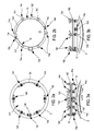
- en
figure 1 , une vue perspective d'un exemple de trou d'homme dans une citerne équipée d'un couvercle muni de supports d'articulation de charnière et de boulons basculants selon l'invention; - en
figures 2a et 2b , des vues de dessus et de dessous du couvercle muni d'une charnière et de boulons basculants selon lafigure 1 ; et - en
figures 3a et 3b , des vues latérales respectivement selon l'axe longitudinal de la citerne et orthogonalement à cet axe.
- in
figure 1 , a perspective view of an example of a manhole in a tank equipped with a lid provided with hinge hinge supports and rocker bolts according to the invention; - in
Figures 2a and 2b , top and bottom views of the hinged lid and rocker bolts in accordance with thefigure 1 ; and - in
Figures 3a and 3b , lateral views respectively along the longitudinal axis of the tank and orthogonal to this axis.
Des signes de référence identiques ou dérivés, utilisés dans les différentes figures, se rapportent à des éléments identiques, décrits dans les passages qui s'y réfèrent. Les termes « supérieur », « médian » et « inférieur » se réfèrent au positionnement relatif en mode standard d'utilisation ou de montage. Les termes « longitudinal » et « transversal » qualifient des éléments s'étendant selon une direction et un plan perpendiculaire à cette direction, en particulier « longitudinal » renvoie à l'axe principal X'X dans lequel s'étend la citerne.Identical or derivative reference signs used in the various figures refer to identical elements, described in the passages which refer to them. The terms "upper", "middle" and "lower" refer to relative positioning in standard mode of use or mounting. The terms "longitudinal" and "transverse" describe elements extending in a direction and a plane perpendicular to this direction, in particular "longitudinal" refers to the main axis X'X in which the tank extends.
En référence à la vue en perspective d'un exemple de réalisation de l'invention de la
- une
poignée 125 agencée de manière diamétralement opposée à unecharnière 130 d'articulation ducouvercle 100 sur le trou d'homme 10.
- a
handle 125 arranged diametrically opposite ahinge 130 for hinging thelid 100 on themanhole 10.
La charnière 130 comporte :
- un support d'articulation 13a constitué d'une
embase 131, en position horizontale en mode d'utilisation, terminée par deuxoreilles 132 dressées verticalement ; un axe d'articulation 133 montée dans les oreilles et fixépar une goupille 134 à chaque extrémité de l'axe 133 ;- deux vis à oeil 135, verrouillées de part et d'autre du couvercle 100 par des écrous 136, et terminées par des anneaux 137 montés en rotation sur l'axe 133.
- a
hinge support 13a consisting of abase 131, in horizontal position in the use mode, terminated by twoears 132 erected vertically; - a
hinge pin 133 mounted in the ears and fixed by apin 134 at each end of theaxis 133; - two
eye screws 135, locked on either side of thecover 100 bynuts 136, and terminated byrings 137 rotatably mounted on theaxis 133.
De plus, le couvercle 100 est fermé de manière amovible par six boulons basculants 140. Ces boulons basculants 140 sont accueillis dans des encoches 101, formées sur la circonférence du couvercle 100 selon une répartition régulière. Chaque boulon basculant 140 comporte :
un support d'articulation 14a constitué d'une embase 141, en position horizontale en mode d'utilisation, terminée par deux oreilles 142 dressées verticalement ;un axe d'articulation 143 montée dans les oreilles et fixépar une goupille 144 à chaque extrémité de l'axe 143 ;- une vis à oeil 145 munie d'une manette à deux
bras 146 ; la vis 145 est terminéepar un anneau 147 monté en rotation sur l'axe 143, après avoir traversée une platine 148 équipée d'une vis de serrage à tête hexagonale 149.
- a
hinge support 14a consisting of abase 141, in horizontal position in the use mode, terminated by twoears 142 erected vertically; - a
hinge pin 143 mounted in the ears and fixed by apin 144 at each end of theaxis 143; - an
eye screw 145 provided with a handle with twoarms 146; thescrew 145 is terminated by aring 147 rotatably mounted on theaxis 143, after passing through aplate 148 equipped with ahexagonal screw clamp 149.
Selon l'exemple de réalisation illustré par la
Les oreilles 132, 142 et les embases 131, 141 des supports d'articulation 13a, 14a, respectivement de la charnière 13 et de chaque boulon basculant 14, sont solidarisés à la face externe 15e de la paroi cylindrique 150 du collier de serrage 15. Dans l'exemple illustré, les supports d'articulation 13a, 14a sont soudés à la face externe 15e du collier de serrage 15. Alternativement, ces supports de serrage 13a, 14a peuvent être collés, avec une colle appropriée au collage métal/métal, ou peuvent être rivetés, clinchés ou encore sertis dans la paroi cylindrique 150.The
La vue de dessus de la
La vue de dessous de la
La vue latérale selon l'axe longitudinal X'X de la
Le collier 15 est avantageusement disposé sous un rebord 16 formé en extrémité de la réhausse 12 afin de positionner les supports d'articulation de manière uniforme sous ce rebord 16.The
La
L'invention n'est pas limitée aux exemples de réalisation décrits et représentés. Le cerclage de la rehausse peut être également réalisé par un joint ou une gaine cylindrique. Il est possible de prévoir d'autres dispositifs de fermeture amovible que les boulons basculants, par exemple des crochets ou des clips de fixation amovibles. Par ailleurs, le collier de serrage peut être constitué d'un seul tenant avec des moyens de serrage entre ses extrémités, de deux demi-colliers - comme dans l'exemple détaillé - ou de plus de deux demi-colliers. En outre, les moyens de serrage ajustable peuvent être constitués de pince de serrage, de pots de serrage ou de prise de mors.The invention is not limited to the embodiments described and shown. The strapping of the riser can also be achieved by a gasket or a cylindrical sheath. It is possible to provide other removable closure devices that the rocking bolts, for example hooks or removable fastening clips. Moreover, the clamping collar may consist of a single piece with clamping means between its ends, two half-collars - as in the detailed example - or more than two half-collars. In addition, the adjustable clamping means may consist of clamp, clamping jaws or grip jaws.
Claims (9)
Applications Claiming Priority (1)
| Application Number | Priority Date | Filing Date | Title |
|---|---|---|---|
| FR1261983A FR2999544B1 (en) | 2012-12-13 | 2012-12-13 | METHOD FOR FASTENING A CISTERN ORIFICE COVER IN COMPOSITE MATERIAL AND CORRESPONDING TANK |
Publications (1)
| Publication Number | Publication Date |
|---|---|
| EP2743210A1 true EP2743210A1 (en) | 2014-06-18 |
Family
ID=48521036
Family Applications (1)
| Application Number | Title | Priority Date | Filing Date |
|---|---|---|---|
| EP13196942.0A Withdrawn EP2743210A1 (en) | 2012-12-13 | 2013-12-12 | Method for attaching a lid of a tank opening made of composite material and corresponding tank |
Country Status (2)
| Country | Link |
|---|---|
| EP (1) | EP2743210A1 (en) |
| FR (1) | FR2999544B1 (en) |
Cited By (2)
| Publication number | Priority date | Publication date | Assignee | Title |
|---|---|---|---|---|
| CN104859523A (en) * | 2015-04-13 | 2015-08-26 | 泰州市建业车件制造有限公司 | External inlet assembly for dust tank car |
| EP3085643A1 (en) * | 2015-04-21 | 2016-10-26 | De Dietrich | Integral and quick opening/closing device for a manhole |
Citations (5)
| Publication number | Priority date | Publication date | Assignee | Title |
|---|---|---|---|---|
| JPS5311380U (en) * | 1976-07-12 | 1978-01-30 | ||
| US4137669A (en) * | 1978-02-08 | 1979-02-06 | Sybron Corporation | Balancing mechanism for manhole covers |
| JPH06127595A (en) * | 1992-10-13 | 1994-05-10 | Yatsumine Sangyo Kk | Device for suppressing deformation of cover for liquid injecting port in liquid transferring tank |
| US6196590B1 (en) * | 1999-07-09 | 2001-03-06 | Sun Y. Kim | Slide hatch for bulk carrier |
| US20070235463A1 (en) * | 2006-03-29 | 2007-10-11 | Wyler Norman C | Manway sealing system |
-
2012
- 2012-12-13 FR FR1261983A patent/FR2999544B1/en active Active
-
2013
- 2013-12-12 EP EP13196942.0A patent/EP2743210A1/en not_active Withdrawn
Patent Citations (5)
| Publication number | Priority date | Publication date | Assignee | Title |
|---|---|---|---|---|
| JPS5311380U (en) * | 1976-07-12 | 1978-01-30 | ||
| US4137669A (en) * | 1978-02-08 | 1979-02-06 | Sybron Corporation | Balancing mechanism for manhole covers |
| JPH06127595A (en) * | 1992-10-13 | 1994-05-10 | Yatsumine Sangyo Kk | Device for suppressing deformation of cover for liquid injecting port in liquid transferring tank |
| US6196590B1 (en) * | 1999-07-09 | 2001-03-06 | Sun Y. Kim | Slide hatch for bulk carrier |
| US20070235463A1 (en) * | 2006-03-29 | 2007-10-11 | Wyler Norman C | Manway sealing system |
Cited By (3)
| Publication number | Priority date | Publication date | Assignee | Title |
|---|---|---|---|---|
| CN104859523A (en) * | 2015-04-13 | 2015-08-26 | 泰州市建业车件制造有限公司 | External inlet assembly for dust tank car |
| EP3085643A1 (en) * | 2015-04-21 | 2016-10-26 | De Dietrich | Integral and quick opening/closing device for a manhole |
| FR3035384A1 (en) * | 2015-04-21 | 2016-10-28 | De Dietrich | FULL AND RAPID OPENING / CLOSING DEVICE FOR MANHOLE |
Also Published As
| Publication number | Publication date |
|---|---|
| FR2999544B1 (en) | 2014-12-05 |
| FR2999544A1 (en) | 2014-06-20 |
Similar Documents
| Publication | Publication Date | Title |
|---|---|---|
| FR2973165B1 (en) | BATTERY BOX | |
| EP2476162B1 (en) | Radome and fastening device for this radom on an aircraft | |
| FR2878915A1 (en) | Flush-mounted assembly component for sandwich panel used e.g. in aircraft comprises plastic housing with disc, plug and inner fixing element | |
| EP2743210A1 (en) | Method for attaching a lid of a tank opening made of composite material and corresponding tank | |
| FR2986767A1 (en) | ARRANGEMENT FOR A MOTOR VEHICLE WITH A WATER BOX IN THREE ELEMENTS | |
| FR2463074A1 (en) | CLOSURE CAP FOR A GOULOT VERSEUR CONTAINER | |
| WO2020229283A1 (en) | Glazing unit having two-part glass pane holder, and method for manufacturing the glazing unit | |
| EP0383745A1 (en) | Container | |
| FR2956859A1 (en) | Freight container for transporting e.g. nuclear waste, has walls and top part forming unitary assembly in form of cover removable with respect to base, where base comprises locking and fixation units cooperating with inner frame of cover | |
| FR3036011B1 (en) | SYSTEM FOR FIXING A PANEL ON A LONGERON AND CARRIER STRUCTURE COMPRISING IT | |
| WO2020127971A1 (en) | Flexible container for packaging waste | |
| FR2613334A1 (en) | CONTAINER FOR HEAVY LOADS | |
| FR2781461A1 (en) | Container for transporting blood bags, has catching portion in shape of fold and reduced thickness linking portion connecting catching portion to envelope side | |
| CA3087559A1 (en) | Improvement to a deflector for protecting the feet of a structure | |
| EP1879791B1 (en) | Device for fastening rigging elements, and mast equipped with same | |
| EP3165807B1 (en) | Protective cap for a gas cylinder | |
| WO2017191145A1 (en) | Item of luggage having a device for stiffening the lips of a closure | |
| BE844740R (en) | HYDRAULIC SEALER FOR MINES | |
| WO2022090502A1 (en) | Buckle for securing together end portions of a strap and use thereof | |
| BE893799Q (en) | LID FOR TRANSPORT CONTAINERS IN PLASTIC MATERIAL | |
| EP3766805A1 (en) | Sealed lid for waste collection container | |
| FR2485488A1 (en) | CLOSURE FOR PACKAGING CONTAINER OF SYNTHETIC MATERIAL AND MANUFACTURING METHOD THEREOF | |
| FR2730710A1 (en) | Sealing of container containing dangerous materials | |
| FR3056161A1 (en) | VEHICLE SEAT BACKREST STRUCTURE | |
| EP1705308A1 (en) | Fastening system for a building dome und unit comprising such a dome, a connecting piece and fastening means |
Legal Events
| Date | Code | Title | Description |
|---|---|---|---|
| PUAI | Public reference made under article 153(3) epc to a published international application that has entered the european phase |
Free format text: ORIGINAL CODE: 0009012 |
|
| 17P | Request for examination filed |
Effective date: 20131212 |
|
| AK | Designated contracting states |
Kind code of ref document: A1 Designated state(s): AL AT BE BG CH CY CZ DE DK EE ES FI FR GB GR HR HU IE IS IT LI LT LU LV MC MK MT NL NO PL PT RO RS SE SI SK SM TR |
|
| AX | Request for extension of the european patent |
Extension state: BA ME |
|
| STAA | Information on the status of an ep patent application or granted ep patent |
Free format text: STATUS: THE APPLICATION IS DEEMED TO BE WITHDRAWN |
|
| 18D | Application deemed to be withdrawn |
Effective date: 20141219 |