EP2695031B1 - Thermal management system - Google Patents
Thermal management system Download PDFInfo
- Publication number
- EP2695031B1 EP2695031B1 EP12768250.8A EP12768250A EP2695031B1 EP 2695031 B1 EP2695031 B1 EP 2695031B1 EP 12768250 A EP12768250 A EP 12768250A EP 2695031 B1 EP2695031 B1 EP 2695031B1
- Authority
- EP
- European Patent Office
- Prior art keywords
- electromagnet
- component
- target component
- particles
- thermally conductive
- Prior art date
- Legal status (The legal status is an assumption and is not a legal conclusion. Google has not performed a legal analysis and makes no representation as to the accuracy of the status listed.)
- Active
Links
- 239000002245 particle Substances 0.000 claims description 60
- 239000012530 fluid Substances 0.000 claims description 40
- CWYNVVGOOAEACU-UHFFFAOYSA-N Fe2+ Chemical compound [Fe+2] CWYNVVGOOAEACU-UHFFFAOYSA-N 0.000 claims description 39
- 238000000034 method Methods 0.000 claims description 22
- 230000005291 magnetic effect Effects 0.000 claims description 14
- 125000006850 spacer group Chemical group 0.000 claims description 9
- 239000000463 material Substances 0.000 claims description 8
- LYCAIKOWRPUZTN-UHFFFAOYSA-N Ethylene glycol Chemical compound OCCO LYCAIKOWRPUZTN-UHFFFAOYSA-N 0.000 description 9
- XEEYBQQBJWHFJM-UHFFFAOYSA-N Iron Chemical compound [Fe] XEEYBQQBJWHFJM-UHFFFAOYSA-N 0.000 description 8
- 238000005286 illumination Methods 0.000 description 7
- 229910052742 iron Inorganic materials 0.000 description 4
- 239000002105 nanoparticle Substances 0.000 description 4
- 238000013459 approach Methods 0.000 description 3
- 238000001816 cooling Methods 0.000 description 3
- 239000012782 phase change material Substances 0.000 description 3
- 239000011554 ferrofluid Substances 0.000 description 2
- 230000005294 ferromagnetic effect Effects 0.000 description 2
- XLYOFNOQVPJJNP-UHFFFAOYSA-N water Substances O XLYOFNOQVPJJNP-UHFFFAOYSA-N 0.000 description 2
- RYGMFSIKBFXOCR-UHFFFAOYSA-N Copper Chemical compound [Cu] RYGMFSIKBFXOCR-UHFFFAOYSA-N 0.000 description 1
- HCHKCACWOHOZIP-UHFFFAOYSA-N Zinc Chemical compound [Zn] HCHKCACWOHOZIP-UHFFFAOYSA-N 0.000 description 1
- 229910052782 aluminium Inorganic materials 0.000 description 1
- XAGFODPZIPBFFR-UHFFFAOYSA-N aluminium Chemical compound [Al] XAGFODPZIPBFFR-UHFFFAOYSA-N 0.000 description 1
- 229910052802 copper Inorganic materials 0.000 description 1
- 239000010949 copper Substances 0.000 description 1
- 230000003247 decreasing effect Effects 0.000 description 1
- 230000000694 effects Effects 0.000 description 1
- 239000013536 elastomeric material Substances 0.000 description 1
- 239000011521 glass Substances 0.000 description 1
- 238000010438 heat treatment Methods 0.000 description 1
- 229910052595 hematite Inorganic materials 0.000 description 1
- 239000011019 hematite Substances 0.000 description 1
- 238000003384 imaging method Methods 0.000 description 1
- 230000002401 inhibitory effect Effects 0.000 description 1
- -1 iron Chemical class 0.000 description 1
- LIKBJVNGSGBSGK-UHFFFAOYSA-N iron(3+);oxygen(2-) Chemical compound [O-2].[O-2].[O-2].[Fe+3].[Fe+3] LIKBJVNGSGBSGK-UHFFFAOYSA-N 0.000 description 1
- SZVJSHCCFOBDDC-UHFFFAOYSA-N iron(II,III) oxide Inorganic materials O=[Fe]O[Fe]O[Fe]=O SZVJSHCCFOBDDC-UHFFFAOYSA-N 0.000 description 1
- 238000005259 measurement Methods 0.000 description 1
- 229910052751 metal Inorganic materials 0.000 description 1
- 239000002184 metal Substances 0.000 description 1
- 150000001247 metal acetylides Chemical class 0.000 description 1
- 238000004806 packaging method and process Methods 0.000 description 1
- 229910052573 porcelain Inorganic materials 0.000 description 1
- 230000001846 repelling effect Effects 0.000 description 1
- 230000004044 response Effects 0.000 description 1
- 230000000153 supplemental effect Effects 0.000 description 1
- 229910052725 zinc Inorganic materials 0.000 description 1
- 239000011701 zinc Substances 0.000 description 1
Images

Classifications
-
- H—ELECTRICITY
- H01—ELECTRIC ELEMENTS
- H01S—DEVICES USING THE PROCESS OF LIGHT AMPLIFICATION BY STIMULATED EMISSION OF RADIATION [LASER] TO AMPLIFY OR GENERATE LIGHT; DEVICES USING STIMULATED EMISSION OF ELECTROMAGNETIC RADIATION IN WAVE RANGES OTHER THAN OPTICAL
- H01S5/00—Semiconductor lasers
- H01S5/02—Structural details or components not essential to laser action
- H01S5/024—Arrangements for thermal management
-
- G—PHYSICS
- G05—CONTROLLING; REGULATING
- G05D—SYSTEMS FOR CONTROLLING OR REGULATING NON-ELECTRIC VARIABLES
- G05D23/00—Control of temperature
- G05D23/19—Control of temperature characterised by the use of electric means
- G05D23/1919—Control of temperature characterised by the use of electric means characterised by the type of controller
- G05D23/192—Control of temperature characterised by the use of electric means characterised by the type of controller using a modification of the thermal impedance between a source and the load
-
- G—PHYSICS
- G05—CONTROLLING; REGULATING
- G05D—SYSTEMS FOR CONTROLLING OR REGULATING NON-ELECTRIC VARIABLES
- G05D23/00—Control of temperature
- G05D23/19—Control of temperature characterised by the use of electric means
- G05D23/20—Control of temperature characterised by the use of electric means with sensing elements having variation of electric or magnetic properties with change of temperature
-
- H—ELECTRICITY
- H01—ELECTRIC ELEMENTS
- H01S—DEVICES USING THE PROCESS OF LIGHT AMPLIFICATION BY STIMULATED EMISSION OF RADIATION [LASER] TO AMPLIFY OR GENERATE LIGHT; DEVICES USING STIMULATED EMISSION OF ELECTROMAGNETIC RADIATION IN WAVE RANGES OTHER THAN OPTICAL
- H01S3/00—Lasers, i.e. devices using stimulated emission of electromagnetic radiation in the infrared, visible or ultraviolet wave range
- H01S3/02—Constructional details
- H01S3/04—Arrangements for thermal management
Definitions
- Electronic components may be designed to operate within a desired temperature range between an upper and a lower target temperature.
- one input device for a gaming system is a depth camera.
- Depth cameras typically include an illumination system with a light source to illuminate an object with illumination light.
- the light source should be maintained within a desired temperature range.
- thermal management devices such as cooling fans or thermoelectric coolers (TECs).
- TECs thermoelectric coolers
- thermal management devices may be expensive and may require an amount of packaging space that is undesirable in certain electronic systems, such as gaming systems.
- these and other approaches to maintaining a desired temperature range may provide either a heating or cooling effect to an electronic component, but may be less effective at thermally isolating the component.
- DE 102008040281 A1 corresponding US 2011/167838 A1 , describes a device for cooling components, comprising a housing in which a cavity is formed, in which a phase-change material is accommodated, the housing having at least one surface, which is able to be brought into contact with the component to be cooled, and at least one heat-dissipating surface.
- the cavity accommodating the phase-change material is enclosed by at least one coil, and the phase-change material includes ferromagnetic or magnetizable particles.
- the thermal management system includes a first component having a first surface that is proximate to the target component.
- An electromagnet is positioned between the first surface and the target component.
- a second component is spaced apart from the first component to create a gap between the first and second components that serves as a thermal boundary between the components.
- a carrier fluid is disposed within the gap and includes multiple thermally conductive, ferrous particles.
- the carrier fluid When the electromagnet generates a magnetic field that attracts the thermally conductive, ferrous particles, the carrier fluid is configured to align at least a portion of the particles across a central region of the gap. Conversely, when the electromagnet generates a magnetic field that repels the particles, the carrier fluid is configured to displace at least a portion of the particles from a central region of the gap. In this manner, the thermal management system operates to selectively thermally connect and thermally isolate the first and second components.
- FIG. 1 schematically shows an example of a gaming system 10 that includes a computing device 12, such as a game console, and associated depth camera 20 with which a thermal management system according to an embodiment of the present disclosure may be utilized.
- the depth camera 20 emits light that illuminates an object, such as person 28, and senses reflected illuminated light at a light sensor.
- An imaging system within the depth camera 20 or computing device 12 is configured to generate an object image based on the reflected light that is captured.
- the object image may be used to present a graphical representation 32 of the illuminated object on a display 36.
- FIG. 2 schematically shows components of the depth camera 20 and computing device 12 of FIG. 1 .
- depth camera 20 includes a controller 40, memory 50 and power supply 60.
- Depth camera 20 also includes a light source 14 that is disposed within an illumination system 18.
- the depth camera 20 further includes a thermal management system 100 according to an embodiment of the present disclosure for selectively thermally isolating and thermally connecting a target component 30, such the light source 14.
- the illumination system 18 may control the light source 14 to illuminate an object, such as the person 28 in FIG. 1 .
- the illumination light may be structured light used to provide an interference pattern that is analyzed to determine three-dimensional information.
- the illumination light may be pulsed light used to provide a basis for time-of-flight measurements to determine three-dimensional information.
- the light source 14 may include an array of light emitting laser diodes 16 that are controlled to emit pulses of light at one or more wavelengths. It will be appreciated the light emitting laser diodes 16 generate heat, and that varying the operating temperature of the light emitting diodes 16 will also vary the emission wavelength of the emitted light. Increasing the operating temperature of the laser diode results in a corresponding increase in the wavelength of the emitted light. Conversely, decreasing the operating temperature of the laser diode results in a corresponding decrease in the wavelength of the emitted light. For reference and example purposes only, a theoretical 30 degree Celsius adjustment of the operating temperature of a standard edge emitting Fabret-Perot laser may result in a 10 nm wavelength shift of the emitted light.
- the computing device 12 includes a controller 72, memory 74, and associated mass storage device 76 and power supply 78.
- Computing device 12 is operably connected to the depth camera 20 to receive three-dimensional information from the depth camera.
- the depth camera 20 may not include a controller or memory, and the controller 72 and memory 74 of the computing device 12 may be used to control the depth camera and thermal management system 100.
- thermal management system 100 may be embedded in or operably connected to other electronic devices that provide one or more of a power supply, controller, mass storage, and/or memory. Accordingly, the embodiments of the thermal management system 100 described herein are merely illustrative, and other suitable embodiments in other operating contexts may be employed within the scope of the present disclosure.
- One approach to minimizing such a wavelength shift may be to maintain the operating temperature of the light emitting laser diodes 16 within a desired temperature range.
- the target component 30 may be one or more light emitting laser diodes 16 within a light source 14.
- thermal management system 100 may include a first component 202 that includes a first surface 206 proximate to the target component 30.
- a first electromagnet 210 may be disposed between the first surface 206 and the target component 30.
- the first electromagnet 210 may be comprised of a coil surrounding a ferromagnetic core.
- the first electromagnet 210 may have a toroidal shape.
- the first surface 206 of the first component 202 may be proximate to the target component 30 but may not be in contact with the target component.
- at least a portion of the first surface 206 may be proximate to and in contact with the target component 30.
- a width of the first electromagnet 210 may be less than a width of the first component 202, and an outer periphery of the first component and first surface 206 may extend to contact the target component 30.
- a second component 214 may be spaced apart from the first component 202 to form a gap 220.
- the gap 220 serves as a thermal boundary between the first component 202 and the second component 214.
- the second component 214 includes a second surface 208 proximate to a heat sink 270.
- the heat sink 270 may operate to lower the temperature of the second component 214, and thereby create a larger temperature difference between the second component 214 and the target component 30. As described in more detail below, in this manner the heat sink 270 may selectively enhance heat transfer from the target component 30.
- an existing heat sink 274 may be present in the electronic component with which the thermal management system 100 is used. In this embodiment, the existing heat sink 274 may be used in addition to or in place of heat sink 270.
- a second magnet 310 may be disposed between the second surface 208 and the heat sink 270.
- the second magnet 310 may be a permanent magnet or a second electromagnet.
- the second magnet 310 may be a permanent magnet, and the controller 40 is configured to selectively control the first electromagnet 210 as described in more detail below.
- the second magnet 310 is a second electromagnet that is also electrically connected to the power supply 60, and the controller 40 is configured to selectively control the first electromagnet 210 and the second electromagnet as described in more detail below.
- the second surface 208 of the second component 214 may be proximate to the heat sink 270 but may not be in contact with the heat sink 270. In other embodiments, at least a portion of the second surface 208 of the second component 214 may be proximate to and in contact with the heat sink 270.
- a width of the second magnet 310 may be less than a width of the second component 214, and an outer periphery of the second component and second surface 208 may extend to contact the heat sink 270.
- the first component 202 and the second component 214 may be separated by a spacer 224 that is formed from a material having a first thermal conductivity that is lower than a second thermal conductivity of the first component and the second component.
- a spacer 224 that is formed from a material having a first thermal conductivity that is lower than a second thermal conductivity of the first component and the second component. Examples of materials that may be used for the spacer 24 include glass, porcelain, plastic and elastomeric materials.
- the spacer 224 may be an O-ring formed of an elastomeric material.
- the first component 202 and the second component 214 may comprise ring-shaped plates positioned opposite to one another.
- the first component 202 and second component 214 may be separated by and overlap the spacer 224, which may comprise an elastomeric O-ring.
- the first electromagnet 210 may similarly comprise a ring-shaped plate having a diameter less than the diameter of the first component 202 and second component 214.
- the first component 202 and the second component 214 may be formed from a non-ferrous material. As noted above, the first component 202 and the second component 214 are also formed from a material having a second thermal conductivity that is higher than a first thermal conductivity of the spacer 24. Examples of non-ferrous materials that may be used for the first component 202 and the second component 214 include aluminum, zinc and copper.
- the first electromagnet 210 may be electrically connected to power supply 60 for selectively energizing the first electromagnet to generate a magnetic field that propagates through the first component 202 and into the gap 220.
- the power supply 60 may be operably connected to controller 40 that is configured to selectively control the first electromagnet 210 by providing electric current from the power supply to the first electromagnet.
- the controller 40 may be operably connected to a temperature sensor 70 that is operably connected to the target component 30.
- Memory 50 includes program logic instructions stored thereon and executed by the controller 40 to selectively control the power supply 60 to energize the first electromagnet 210 and provide the functionality described herein.
- the carrier fluid 240 disposed with the gap 220 between the first component 202 and the second component 214 is a carrier fluid 240 that includes multiple thermally conductive, ferrous particles 246.
- the carrier fluid 240 may comprise a colloidal solution comprising a base fluid and thermally conductive, ferrous nanoparticles suspended within the base fluid.
- Each of the nanoparticles may have a diameter of between approximately 1-100 nanometers, and may be formed from materials including, but not limited to oxides, carbides, or metal such as iron, magnetite, or hematite..
- Base fluids in which the nanoparticles may be suspended include water, ethylene glycol, or other fluids, some of which may have a thermal conductivity lower than water or ethylene glycol. It will be appreciated that the thermal conductivity of the base fluid is less than the thermal conductivity of the thermally conductive, ferrous nanoparticles.
- ethylene glycol may have a thermal conductivity of approximately 0.25 W/mK
- iron may have a thermal conductivity of approximately 80 W/mK.
- the carrier fluid 240 is configured to align the thermally conductive, ferrous particles 246 across a central region 226 of the gap 220 when the first electromagnet 210 and/or second magnet 310 generates a magnetic field that attracts the particles.
- the carrier fluid 240 is also configured to displace the particles from the central region 226 of the gap 220 when the first electromagnet 210 and/or second magnet 310 generates a magnetic field that repels the particles.
- the central region 226 of the gap 220 may be positioned substantially opposite to the first electromagnet 210 and may extend laterally beyond the edges 212 and 216 of the first electromagnet. In another example, the central region 226 of the gap 220 may not extend laterally beyond the edges 212 and 216 of the first electromagnet 210.
- the first component 202 and the second component 214 cooperate with the spacer 224 to form a fluidically sealed space, such that the carrier fluid 240 is substantially stationary within the gap 220.
- heat transfer from the first component 202 through the carrier fluid 240 to the target component 30 comprises conductive heat transfer.
- the - temperature of the target component 30 may increase or decrease depending upon various operating conditions and parameters, including but not limited to the duration of operation or non-operation of the target component, and the difference in temperature between the target component and its surroundings.
- the target component 30 may comprise one or more light emitting laser diodes 16 within depth camera 20. As the laser diodes 16 are operated, varying the temperature of the laser diodes will cause the emission wavelength of the emitted light to shift.
- the target operating temperature range may be between a first threshold temperature and a second threshold temperature.
- the first threshold temperature is approximately 42.1 degrees Celsius and the second threshold temperature is approximately 41.9 degrees Celsius. It will be appreciated that other temperatures may be used for the first and second threshold temperatures according to the particular requirements of the target component 30 and its operating conditions. Additionally, in some embodiments the first and second threshold temperatures may be equal.
- the thermal management system 100 may selectively thermally isolate and thermally connect the laser diodes 16 to maintain the laser diodes within the target operating temperature range.
- FIG. 7 a flow chart is provided for a method for selectively thermally isolating and thermally connecting a target component that generates heat, such as laser diodes 16.
- the method may comprise a control algorithm in the form of instructions stored in memory 50.
- the instructions may be executed by controller 40 and performed by the hardware and components illustrated in FIGS. 3 , 5 and 6 and described above. It will be appreciated that the method may also be performed by any other suitable hardware, software and/or components.
- a method 328 comprises controlling the first electromagnet 210 and/or second electromagnet to attract and repel thermally conductive, ferrous particles. More specifically, at step 314 the method includes controlling the first electromagnet 210 and/or second electromagnet to generate a magnetic field that attracts the thermally conductive, ferrous particles 246 within the carrier fluid 240, and thereby aligns at least a portion of the particles across the central region 226 of the gap 220.
- the method also includes controlling the first electromagnet 210 and/or second electromagnet to generate a magnetic field that repels the thermally conductive, ferrous particles 246 within the carrier fluid 240, and thereby displaces at least a portion of the particles from the central region 226 of the gap 220
- aligning the thermally conductive, ferrous particles 246 in the manner described will enhance heat transfer from the target component 30 across the gap to the heat sink 270, whereas displacing the particles in the manner described will inhibit heat transfer across the gap and through the carrier fluid 240.
- the current flow through the first electromagnet 210 and/or second electromagnet may be at a maximum rating of the electromagnet(s) to generate the strongest possible magnet field(s). In another example the current flow may be modulated to values less than the maximum rating of the first electromagnet 210 and/or second electromagnet to vary the intensity of the magnet field(s) generated by the electromagnet(s). The current flow through the first electromagnet 210 and/or second electromagnet may also be eliminated to produce an absence of a magnetic field.
- a method 302 comprises sensing an actual temperature of the target component 30.
- the temperature sensor 70 may determine an actual temperature of the target component 30 and deliver this information to controller 40.
- the actual temperature of the target component is compared to the first threshold temperature.
- the first threshold temperature for example, may be stored in memory 50 and accessed by controller 40.
- the method 300 returns to step 304 to again sense the actual temperature of the target component 30.
- step 316 the actual temperature of the target component is compared to a second threshold temperature.
- the second threshold temperature may also be stored in memory 50 and accessed by controller 40.
- step 320 the method determines whether the actual temperature is below the second threshold temperature. If the actual temperature is not below the second threshold temperature, then the method returns to step 304 to again sense the actual temperature of the target component 30. If the actual temperature of the target component 30 is below the second threshold temperature, and with reference now to FIG.
- the method includes controlling the first electromagnet 210 and/or second electromagnet to generate a magnetic field that repels the thermally conductive, ferrous particles 246 within the carrier fluid 240, and thereby displaces at least a portion of the particles from the central region 226 of the gap 220.
- the method returns to step 304 to again sense the actual temperature of the target component 30.
- repelling the thermally conductive, ferrous particles 246 and displacing at least a portion of the particles from the central region 226 of the gap 220 thermally isolates the target component 30 from the heat sink 270, and inhibits heat transfer from the target component 30 to the heat sink 270.
- the thermal conductivity of the base fluid is less than the thermal conductivity of the thermally conductive, ferrous particles suspended within the base fluid.
- displacing the particles from the central region 226 of the gap 220 leaves primarily only the base fluid within the central region of the gap, which serves to inhibit heat transfer across the gap.
- Such inhibited heat transfer is schematically indicated by the dashed arrow extending only to the first component 202 in FIG. 6 .
- the temperature of the target component 30 may rise by virtue of heat generated by the target component or heat transferred to the target component from other heat sources within the surrounding environment.
- an auxiliary heater 280 may be utilized to provide supplemental heat transfer to the target component 30 as desired.
- the depth camera 20 that includes the laser diodes 16 may be transported through and/or used in an environment with an ambient temperature well below the desired operating temperature range of the laser diodes.
- the target component 30 may be thermally isolated from the heat sink 270 as described above, and the auxiliary heater 280 may be utilized to heat the laser diodes 16 and reduce the time required to raise the temperature of the laser diodes to within their desired operating temperature range.
- the carrier fluid 240 may comprise a ferrofluid in which the entire fluid moves in response to the magnetic field(s) generated by the first electromagnet 210 and second electromagnet.
- the central region 226 of the gap 220 when the ferrofluid is repelled and displaced from the central region 226 of the gap 220, the central region is filled by air or vacuum that thermally isolates the target component 30 from the heat sink 270, and inhibits heat transfer from the target component 30 to the heat sink 270.
- the carrier fluid 240 may comprise air and the thermally conductive, ferrous particles may comprise iron filings.
- the central region 226 of the gap 220 when the iron filings are repelled and displaced from the central region 226 of the gap 220, the central region is filled by air that thermally isolates the target component 30 from the heat sink 270, and inhibits heat transfer from the target component 30 to the heat sink 270.
Description
- Electronic components may be designed to operate within a desired temperature range between an upper and a lower target temperature. For example, one input device for a gaming system is a depth camera. Depth cameras typically include an illumination system with a light source to illuminate an object with illumination light. For efficient operation, the light source should be maintained within a desired temperature range.
- Some approaches to maintaining a desired temperature range in an electronic component include utilizing thermal management devices, such as cooling fans or thermoelectric coolers (TECs). However, such thermal management devices may be expensive and may require an amount of packaging space that is undesirable in certain electronic systems, such as gaming systems. Further, these and other approaches to maintaining a desired temperature range may provide either a heating or cooling effect to an electronic component, but may be less effective at thermally isolating the component.
-
DE 102008040281 A1 , correspondingUS 2011/167838 A1 , describes a device for cooling components, comprising a housing in which a cavity is formed, in which a phase-change material is accommodated, the housing having at least one surface, which is able to be brought into contact with the component to be cooled, and at least one heat-dissipating surface. The cavity accommodating the phase-change material is enclosed by at least one coil, and the phase-change material includes ferromagnetic or magnetizable particles. - Various embodiments are disclosed for a thermal management system that selectively thermally isolates and thermally connects a target component. In one embodiment, the thermal management system includes a first component having a first surface that is proximate to the target component. An electromagnet is positioned between the first surface and the target component. A second component is spaced apart from the first component to create a gap between the first and second components that serves as a thermal boundary between the components. A carrier fluid is disposed within the gap and includes multiple thermally conductive, ferrous particles.
- When the electromagnet generates a magnetic field that attracts the thermally conductive, ferrous particles, the carrier fluid is configured to align at least a portion of the particles across a central region of the gap. Conversely, when the electromagnet generates a magnetic field that repels the particles, the carrier fluid is configured to displace at least a portion of the particles from a central region of the gap. In this manner, the thermal management system operates to selectively thermally connect and thermally isolate the first and second components.
-
-
FIG. 1 is a schematic view of a gaming system including a computing device and an associated depth camera that includes a thermal management system according to an embodiment of the present disclosure. -
FIG. 2 is a schematic view of the depth camera and the computing device ofFIG. 1 showing components of the depth camera and computing device according to an embodiment of the present disclosure. -
FIG. 3 . is a schematic view of the thermal management system ofFIG. 2 showing components of the thermal management system according to an embodiment of the present disclosure. -
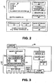
FIG. 4 is a perspective view of the thermal management system ofFIG. 3 showing a first thermally conductive component and a second thermally conductive component separated by a spacer, and a magnet proximate to the first conductive component according to an embodiment of the present disclosure. -
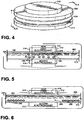
FIG. 5 is a partial cross sectional view of a component stack taken along lines 5,6 ofFIG. 4 and showing a thermal management system operating to align thermally conductive particles across a central region of a gap between a first component and a second component according to an embodiment of the present disclosure. -
FIG. 6 is a partial cross sectional view of the component stack ofFIG. 4 taken along lines 5,6 ofFIG. 4 and showing the thermal management system operating to displace thermally conductive particles from a central region of a gap between a first component and a second component according to an embodiment of the present disclosure. -
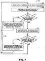
FIG. 7 shows a flow chart for a method of thermally isolating and thermally connecting a target component according to an embodiment of the present disclosure. - Aspects of this disclosure will now be described by example and with reference to the illustrated embodiments listed above.
FIG. 1 schematically shows an example of agaming system 10 that includes a computing device 12, such as a game console, and associateddepth camera 20 with which a thermal management system according to an embodiment of the present disclosure may be utilized. Thedepth camera 20 emits light that illuminates an object, such asperson 28, and senses reflected illuminated light at a light sensor. An imaging system within thedepth camera 20 or computing device 12 is configured to generate an object image based on the reflected light that is captured. The object image may be used to present agraphical representation 32 of the illuminated object on adisplay 36. -
FIG. 2 schematically shows components of thedepth camera 20 and computing device 12 ofFIG. 1 . In oneexample depth camera 20 includes acontroller 40,memory 50 andpower supply 60.Depth camera 20 also includes a light source 14 that is disposed within anillumination system 18. As described in more detail below, thedepth camera 20 further includes athermal management system 100 according to an embodiment of the present disclosure for selectively thermally isolating and thermally connecting atarget component 30, such the light source 14. Theillumination system 18 may control the light source 14 to illuminate an object, such as theperson 28 inFIG. 1 . In some examples, the illumination light may be structured light used to provide an interference pattern that is analyzed to determine three-dimensional information. In some other examples, the illumination light may be pulsed light used to provide a basis for time-of-flight measurements to determine three-dimensional information. - In one example, the light source 14 may include an array of light emitting
laser diodes 16 that are controlled to emit pulses of light at one or more wavelengths. It will be appreciated the light emittinglaser diodes 16 generate heat, and that varying the operating temperature of thelight emitting diodes 16 will also vary the emission wavelength of the emitted light. Increasing the operating temperature of the laser diode results in a corresponding increase in the wavelength of the emitted light. Conversely, decreasing the operating temperature of the laser diode results in a corresponding decrease in the wavelength of the emitted light. For reference and example purposes only, a theoretical 30 degree Celsius adjustment of the operating temperature of a standard edge emitting Fabret-Perot laser may result in a 10 nm wavelength shift of the emitted light. - With continued reference to
FIG. 2 , the computing device 12 includes acontroller 72,memory 74, and associatedmass storage device 76 andpower supply 78. Computing device 12 is operably connected to thedepth camera 20 to receive three-dimensional information from the depth camera. In other examples, thedepth camera 20 may not include a controller or memory, and thecontroller 72 andmemory 74 of the computing device 12 may be used to control the depth camera andthermal management system 100. In still other examples,thermal management system 100 may be embedded in or operably connected to other electronic devices that provide one or more of a power supply, controller, mass storage, and/or memory. Accordingly, the embodiments of thethermal management system 100 described herein are merely illustrative, and other suitable embodiments in other operating contexts may be employed within the scope of the present disclosure. - For efficient operation of the
illumination system 18 within thedepth camera 20, it is desirable to minimize wavelength shift in the lightemitting laser diodes 16. One approach to minimizing such a wavelength shift may be to maintain the operating temperature of the lightemitting laser diodes 16 within a desired temperature range. - With reference now to
FIG. 3 , a schematic representation of atarget component 30 and the components of thethermal management system 100 is provided. As explained above with reference toFIG. 2 , in one example thetarget component 30 may be one or more light emittinglaser diodes 16 within a light source 14. - In one example,
thermal management system 100 may include afirst component 202 that includes afirst surface 206 proximate to thetarget component 30. Afirst electromagnet 210 may be disposed between thefirst surface 206 and thetarget component 30. Thefirst electromagnet 210 may be comprised of a coil surrounding a ferromagnetic core. In one example, thefirst electromagnet 210 may have a toroidal shape. As shown inFIG. 3 , thefirst surface 206 of thefirst component 202 may be proximate to thetarget component 30 but may not be in contact with the target component. In other embodiments, at least a portion of thefirst surface 206 may be proximate to and in contact with thetarget component 30. For example, a width of thefirst electromagnet 210 may be less than a width of thefirst component 202, and an outer periphery of the first component andfirst surface 206 may extend to contact thetarget component 30. - With continued reference to
FIG. 3 , asecond component 214 may be spaced apart from thefirst component 202 to form agap 220. As explained in more detail below, thegap 220 serves as a thermal boundary between thefirst component 202 and thesecond component 214. Thesecond component 214 includes a second surface 208 proximate to aheat sink 270. - The
heat sink 270 may operate to lower the temperature of thesecond component 214, and thereby create a larger temperature difference between thesecond component 214 and thetarget component 30. As described in more detail below, in this manner theheat sink 270 may selectively enhance heat transfer from thetarget component 30. In another example an existingheat sink 274 may be present in the electronic component with which thethermal management system 100 is used. In this embodiment, the existingheat sink 274 may be used in addition to or in place ofheat sink 270. - In one embodiment, a
second magnet 310 may be disposed between the second surface 208 and theheat sink 270. Thesecond magnet 310 may be a permanent magnet or a second electromagnet. In one example, thesecond magnet 310 may be a permanent magnet, and thecontroller 40 is configured to selectively control thefirst electromagnet 210 as described in more detail below. In another example thesecond magnet 310 is a second electromagnet that is also electrically connected to thepower supply 60, and thecontroller 40 is configured to selectively control thefirst electromagnet 210 and the second electromagnet as described in more detail below. - As shown in
FIG. 3 , the second surface 208 of thesecond component 214 may be proximate to theheat sink 270 but may not be in contact with theheat sink 270. In other embodiments, at least a portion of the second surface 208 of thesecond component 214 may be proximate to and in contact with theheat sink 270. For example, a width of thesecond magnet 310 may be less than a width of thesecond component 214, and an outer periphery of the second component and second surface 208 may extend to contact theheat sink 270. - The
first component 202 and thesecond component 214 may be separated by aspacer 224 that is formed from a material having a first thermal conductivity that is lower than a second thermal conductivity of the first component and the second component. Examples of materials that may be used for the spacer 24 include glass, porcelain, plastic and elastomeric materials. In the example shown inFIGS. 3 and4 , thespacer 224 may be an O-ring formed of an elastomeric material. - With reference now to
FIG. 4 , in one example thefirst component 202 and thesecond component 214 may comprise ring-shaped plates positioned opposite to one another. In this embodiment, thefirst component 202 andsecond component 214 may be separated by and overlap thespacer 224, which may comprise an elastomeric O-ring. As shown inFIG. 4 , in this embodiment thefirst electromagnet 210 may similarly comprise a ring-shaped plate having a diameter less than the diameter of thefirst component 202 andsecond component 214. - The
first component 202 and thesecond component 214 may be formed from a non-ferrous material. As noted above, thefirst component 202 and thesecond component 214 are also formed from a material having a second thermal conductivity that is higher than a first thermal conductivity of the spacer 24. Examples of non-ferrous materials that may be used for thefirst component 202 and thesecond component 214 include aluminum, zinc and copper. - With continued reference to
FIG. 3 , thefirst electromagnet 210 may be electrically connected topower supply 60 for selectively energizing the first electromagnet to generate a magnetic field that propagates through thefirst component 202 and into thegap 220. Thepower supply 60 may be operably connected tocontroller 40 that is configured to selectively control thefirst electromagnet 210 by providing electric current from the power supply to the first electromagnet. As explained in more detail below, thecontroller 40 may be operably connected to atemperature sensor 70 that is operably connected to thetarget component 30.Memory 50 includes program logic instructions stored thereon and executed by thecontroller 40 to selectively control thepower supply 60 to energize thefirst electromagnet 210 and provide the functionality described herein. - With reference now to
FIGS. 5 and 6 , disposed with thegap 220 between thefirst component 202 and thesecond component 214 is acarrier fluid 240 that includes multiple thermally conductive,ferrous particles 246. In one example, thecarrier fluid 240 may comprise a colloidal solution comprising a base fluid and thermally conductive, ferrous nanoparticles suspended within the base fluid. Each of the nanoparticles may have a diameter of between approximately 1-100 nanometers, and may be formed from materials including, but not limited to oxides, carbides, or metal such as iron, magnetite, or hematite.. - Base fluids in which the nanoparticles may be suspended include water, ethylene glycol, or other fluids, some of which may have a thermal conductivity lower than water or ethylene glycol. It will be appreciated that the thermal conductivity of the base fluid is less than the thermal conductivity of the thermally conductive, ferrous nanoparticles. For example, ethylene glycol may have a thermal conductivity of approximately 0.25 W/mK, whereas iron may have a thermal conductivity of approximately 80 W/mK. As explained in more detail below, the
carrier fluid 240 is configured to align the thermally conductive,ferrous particles 246 across acentral region 226 of thegap 220 when thefirst electromagnet 210 and/orsecond magnet 310 generates a magnetic field that attracts the particles. Thecarrier fluid 240 is also configured to displace the particles from thecentral region 226 of thegap 220 when thefirst electromagnet 210 and/orsecond magnet 310 generates a magnetic field that repels the particles. - It will be appreciated that aligning the thermally conductive,
ferrous particles 246 across acentral region 226 of thegap 220 will enhance heat transfer across the gap and through thecarrier fluid 240, whereas displacing the particles from the central region of the gap will inhibit heat transfer across the gap and through thecarrier fluid 240. It will also be appreciated that thecentral region 226 of thegap 220 may be positioned substantially opposite to thefirst electromagnet 210 and may extend laterally beyond theedges central region 226 of thegap 220 may not extend laterally beyond theedges first electromagnet 210. - With reference also to
FIG. 3 , thefirst component 202 and thesecond component 214 cooperate with thespacer 224 to form a fluidically sealed space, such that thecarrier fluid 240 is substantially stationary within thegap 220. In this manner, heat transfer from thefirst component 202 through thecarrier fluid 240 to thetarget component 30 comprises conductive heat transfer. - With reference now to
FIG. 3 , it will be appreciated that the - temperature of thetarget component 30 may increase or decrease depending upon various operating conditions and parameters, including but not limited to the duration of operation or non-operation of the target component, and the difference in temperature between the target component and its surroundings. As explained above, in one example thetarget component 30 may comprise one or more light emittinglaser diodes 16 withindepth camera 20. As thelaser diodes 16 are operated, varying the temperature of the laser diodes will cause the emission wavelength of the emitted light to shift. - Also as noted above, it is desirable to operate the
laser diodes 16 within a target operating temperature range to minimize wavelength shift. The target operating temperature range may be between a first threshold temperature and a second threshold temperature. In one example, the first threshold temperature is approximately 42.1 degrees Celsius and the second threshold temperature is approximately 41.9 degrees Celsius. It will be appreciated that other temperatures may be used for the first and second threshold temperatures according to the particular requirements of thetarget component 30 and its operating conditions. Additionally, in some embodiments the first and second threshold temperatures may be equal. As described in more detail below, thethermal management system 100 may selectively thermally isolate and thermally connect thelaser diodes 16 to maintain the laser diodes within the target operating temperature range. - Turning now to
FIG. 7 , and with reference also to the embodiment illustrated inFIGS. 5 and 6 , a flow chart is provided for a method for selectively thermally isolating and thermally connecting a target component that generates heat, such aslaser diodes 16. The method may comprise a control algorithm in the form of instructions stored inmemory 50. The instructions may be executed bycontroller 40 and performed by the hardware and components illustrated inFIGS. 3 ,5 and 6 and described above. It will be appreciated that the method may also be performed by any other suitable hardware, software and/or components. - In one example embodiment beginning with
steps second magnet 310 is a second electromagnet, a method 328 comprises controlling thefirst electromagnet 210 and/or second electromagnet to attract and repel thermally conductive, ferrous particles. More specifically, atstep 314 the method includes controlling thefirst electromagnet 210 and/or second electromagnet to generate a magnetic field that attracts the thermally conductive,ferrous particles 246 within thecarrier fluid 240, and thereby aligns at least a portion of the particles across thecentral region 226 of thegap 220. Atstep 324, the method also includes controlling thefirst electromagnet 210 and/or second electromagnet to generate a magnetic field that repels the thermally conductive,ferrous particles 246 within thecarrier fluid 240, and thereby displaces at least a portion of the particles from thecentral region 226 of thegap 220 As described above, aligning the thermally conductive,ferrous particles 246 in the manner described will enhance heat transfer from thetarget component 30 across the gap to theheat sink 270, whereas displacing the particles in the manner described will inhibit heat transfer across the gap and through thecarrier fluid 240. - In one example the current flow through the
first electromagnet 210 and/or second electromagnet may be at a maximum rating of the electromagnet(s) to generate the strongest possible magnet field(s). In another example the current flow may be modulated to values less than the maximum rating of thefirst electromagnet 210 and/or second electromagnet to vary the intensity of the magnet field(s) generated by the electromagnet(s). The current flow through thefirst electromagnet 210 and/or second electromagnet may also be eliminated to produce an absence of a magnetic field. - In another example embodiment beginning with
step 304, amethod 302 comprises sensing an actual temperature of thetarget component 30. For example, thetemperature sensor 70 may determine an actual temperature of thetarget component 30 and deliver this information tocontroller 40. In thenext step 308, the actual temperature of the target component is compared to the first threshold temperature. The first threshold temperature, for example, may be stored inmemory 50 and accessed bycontroller 40. Next, atstep 312, it is determined whether the actual temperature of the target component is above the first threshold temperature. If the actual temperature of the target component is above the first threshold temperature, then atstep 314 themethod 300 includes controlling thefirst electromagnet 210 and/or second electromagnet to generate a magnetic field that attracts the thermally conductive,ferrous particles 246 within thecarrier fluid 240 as described above. Followingstep 314, themethod 300 returns to step 304 to again sense the actual temperature of thetarget component 30. - With reference now to
FIGS. 3 and5 , it will be appreciated that attracting the thermally conductive,ferrous particles 246 and aligning the particles across thecentral region 226 of thegap 220 thermally connects thetarget component 30 to theheat sink 270 and enhances heat transfer from thetarget component 30 to theheat sink 270. Such enhanced heat transfer is schematically indicated by the dashed arrow extending through thecarrier fluid 240,second component 214 and second electromagnet inFIG. 4 . It will be appreciated that at least a portion of the heat transferred from thetarget component 30 to theheat sink 270 may pass through thefirst electromagnet 210 and second electromagnet. In another example, at least a portion of the heat transferred from thetarget component 30 to theheat sink 270 may not pass through thefirst electromagnet 210 or second electromagnet. - Returning to
FIG. 7 and step 312, if the actual temperature of the target component is not above the first threshold temperature, then atstep 316 the actual temperature of the target component is compared to a second threshold temperature. The second threshold temperature may also be stored inmemory 50 and accessed bycontroller 40. Next, atstep 320 the method determines whether the actual temperature is below the second threshold temperature. If the actual temperature is not below the second threshold temperature, then the method returns to step 304 to again sense the actual temperature of thetarget component 30. If the actual temperature of thetarget component 30 is below the second threshold temperature, and with reference now toFIG. 6 , then atstep 324 the method includes controlling thefirst electromagnet 210 and/or second electromagnet to generate a magnetic field that repels the thermally conductive,ferrous particles 246 within thecarrier fluid 240, and thereby displaces at least a portion of the particles from thecentral region 226 of thegap 220. Followingstep 324, the method returns to step 304 to again sense the actual temperature of thetarget component 30. - With reference now to
FIGS. 3 and6 , it will be appreciated that repelling the thermally conductive,ferrous particles 246 and displacing at least a portion of the particles from thecentral region 226 of thegap 220 thermally isolates thetarget component 30 from theheat sink 270, and inhibits heat transfer from thetarget component 30 to theheat sink 270. As noted above with respect to thecarrier fluid 240, the thermal conductivity of the base fluid is less than the thermal conductivity of the thermally conductive, ferrous particles suspended within the base fluid. Thus, displacing the particles from thecentral region 226 of thegap 220 leaves primarily only the base fluid within the central region of the gap, which serves to inhibit heat transfer across the gap. Such inhibited heat transfer is schematically indicated by the dashed arrow extending only to thefirst component 202 inFIG. 6 . - By inhibiting heat transfer across the
gap 220 and thermally isolating thetarget component 30 from theheat sink 270, the temperature of thetarget component 30 may rise by virtue of heat generated by the target component or heat transferred to the target component from other heat sources within the surrounding environment. With reference toFIG. 3 , in one embodiment anauxiliary heater 280 may be utilized to provide supplemental heat transfer to thetarget component 30 as desired. In one example use case, thedepth camera 20 that includes thelaser diodes 16 may be transported through and/or used in an environment with an ambient temperature well below the desired operating temperature range of the laser diodes. In this example, thetarget component 30 may be thermally isolated from theheat sink 270 as described above, and theauxiliary heater 280 may be utilized to heat thelaser diodes 16 and reduce the time required to raise the temperature of the laser diodes to within their desired operating temperature range. - In another example, the
carrier fluid 240 may comprise a ferrofluid in which the entire fluid moves in response to the magnetic field(s) generated by thefirst electromagnet 210 and second electromagnet. In this example, when the ferrofluid is repelled and displaced from thecentral region 226 of thegap 220, the central region is filled by air or vacuum that thermally isolates thetarget component 30 from theheat sink 270, and inhibits heat transfer from thetarget component 30 to theheat sink 270. - In another example, the
carrier fluid 240 may comprise air and the thermally conductive, ferrous particles may comprise iron filings. In this example, when the iron filings are repelled and displaced from thecentral region 226 of thegap 220, the central region is filled by air that thermally isolates thetarget component 30 from theheat sink 270, and inhibits heat transfer from thetarget component 30 to theheat sink 270.
Claims (11)
- A thermal management system (100) for selectively thermally isolating and thermally connecting a target component (30), comprising:a first component (202) having a first surface (206) proximate to the target component (30);a first electromagnet (210) between the first surface (206) and the target component (30);a second component (214) spaced apart from the first component (202);a gap (220) serving as a thermal boundary between the first component (202) and the second component (214);a carrier fluid (240) disposed within the gap (220) and including a colloidal solution comprising a base fluid and multiple thermally conductive, ferrous particles (246), wherein a thermal conductivity of the base fluid is less than a thermal conductivity of the thermally conductive, ferrous particles suspended within the base fluid, the carrier fluid (240) being configured to align at least a portion of the thermally conductive, ferrous particles (246) across a central region (226) of the gap (220) when the first electromagnet (210) generates a magnetic field that attracts the particles (246), and to displace at least a portion of the particles (246) from the central region (226) of the gap (220) when the first electromagnet (210) generates a magnetic field that repels the particles (246), the carrier fluid (240) and the first electromagnet (210) operating to selectively thermally connect and thermally isolate the target component (30).
- The system (100) of claim 1, further including:a second electromagnet (310) proximate to the second component (214);a power supply (60) configured to supply power to the first electromagnet (210) and the second electromagnet (310); anda controller (40) operably connected to the power supply (60) and configured to selectively control the first electromagnet (210) and the second electromagnet (310) to either attract at least a portion of the thermally conductive, ferrous particles (246) and align the particles (246) across the central region (226) of the gap (220), or to repel at least a portion of the thermally conductive, ferrous particles (246) and displace the particles (246) from the central region (226) of the gap (220).
- The system (100) of claim 2, further comprising instructions executed by the controller (40) to selectively control the power supply (60) to energize the first electromagnet (210) to generate a magnetic field that either aligns the thermally conductive, ferrous particles (246) across the central region (226) of the gap (220), or displaces the thermally conductive, ferrous particles (246) from the central region (226) of the gap (220).
- The system (100) of claim 1, wherein the first component (202) and the second component (214) are comprised of a non-ferrous material, and further comprising a spacer (224) between the first component (202) and the second component (214), the spacer (224) having a first thermal conductivity that is lower than a second thermal conductivity of the first component (202) and the second component (214).
- A method (300) for selectively thermally isolating and thermally connecting a target component (30) that generates heat, comprising:controlling (314) a first electromagnet (210) to attract thermally conductive, ferrous particles (246) within a carrier fluid (240) disposed within a gap (220) between the target component (30) and a heat sink (270) and including a colloidal solution comprising a base fluid and the thermally conductive, ferrous particles (246), wherein a thermal conductivity of the base fluid is less than a thermal conductivity of the thermally conductive, ferrous particles suspended within the base fluid, and align at least a portion of the particles (246) across a central region (226) of the gap (220) between the target component (30) and the heat sink (270) that is spaced apart across the gap (220) from the target component (30) to enhance heat transfer from the target component (30) to the heat sink (270), andcontrolling (324) the first electromagnet (210) to repel the thermally conductive, ferrous particles (246) and displace at least a portion of the particles (246) from the central region (226) of the gap (220) between the target component (30) and the heat sink (270) to inhibit heat transfer from the target component (30) to the heat sink (270).
- The method (300) of claim 5, further comprising the steps of:sensing (304) an actual temperature of the target component (30);comparing (308) the actual temperature of the target component (30) to a first threshold temperature; andif the actual temperature is above (312-YES) the first threshold temperature, controlling (314) the first electromagnet (210) to attract at least a portion of the thermally conductive, ferrous particles (246) and enhance heat transfer from the target component (30) to the heat sink (270).
- The method (300) of claim 6, further comprising the steps of:comparing (308) the actual temperature of the target component (30) to a second threshold temperature; andif the actual temperature is below (320-YES) the second threshold temperature, controlling (324) the first electromagnet (210) to repel at least a portion of the thermally conductive, ferrous particles (246) and inhibit heat transfer from the target component (30) to the heat sink (270).
- The method (300) of claim 5, wherein:controlling (314) the first electromagnet (210) to attract thermally conductive, ferrous particles (246) further comprises controlling the first electromagnet (210) in combination with a permanent magnet, that is proximate to the heat sink (270), to attract the thermally conductive, ferrous particles (246) within the carrier fluid (240) and align at least a portion of the particles (246) across the central region (226) of the gap (220) between the target component (30) and the heat sink (270) that is spaced apart across the gap (220) from the target component (30) to enhance heat transfer from the target component (30) to the heat sink (270), andcontrolling (324) the first electromagnet (210) to repel the thermally conductive, ferrous particles (246) further comprises controlling the first electromagnet (210) in combination with the permanent magnet to repel the thermally conductive, ferrous particles (246) and displace at least a portion of the particles (246) from the central region (226) of the gap (220) between the target component (30) and the heat sink (270) to inhibit heat transfer from the target component (30) to the heat sink (270).
- The method (300) of claim 6, wherein a second electromagnet (310) is proximate to the heat sink (270), the method further comprising the step of, if the actual temperature is above (312-YES) the first threshold temperature, controlling the first electromagnet (210) and the second electromagnet (310) to attract at least a portion of the thermally conductive, ferrous particles (246) and enhance heat transfer from the target component (30) to the heat sink (270).
- The method (300) of claim 9, further comprising the steps of:if the actual temperature is below (320-YES) a second threshold temperature, controlling the first electromagnet (210) and the second electromagnet (310) to repel at least a portion of the thermally conductive, ferrous particles (246) and inhibit heat transfer from the target component (30) and the first component (202) to the second component (214).
- A memory (50) including program logic instructions stored thereon which, when executed by a controller (40), cause the controller (40) to perform the method (300) of any one of the claims 5 to 10.
Applications Claiming Priority (2)
| Application Number | Priority Date | Filing Date | Title |
|---|---|---|---|
| US13/080,549 US8503494B2 (en) | 2011-04-05 | 2011-04-05 | Thermal management system |
| PCT/US2012/030218 WO2012138486A2 (en) | 2011-04-05 | 2012-03-23 | Thermal management system |
Publications (3)
| Publication Number | Publication Date |
|---|---|
| EP2695031A2 EP2695031A2 (en) | 2014-02-12 |
| EP2695031A4 EP2695031A4 (en) | 2015-11-25 |
| EP2695031B1 true EP2695031B1 (en) | 2017-02-22 |
Family
ID=46966110
Family Applications (1)
| Application Number | Title | Priority Date | Filing Date |
|---|---|---|---|
| EP12768250.8A Active EP2695031B1 (en) | 2011-04-05 | 2012-03-23 | Thermal management system |
Country Status (7)
| Country | Link |
|---|---|
| US (1) | US8503494B2 (en) |
| EP (1) | EP2695031B1 (en) |
| JP (1) | JP5977813B2 (en) |
| KR (1) | KR101943125B1 (en) |
| CN (1) | CN103460153B (en) |
| ES (1) | ES2620656T3 (en) |
| WO (1) | WO2012138486A2 (en) |
Families Citing this family (7)
| Publication number | Priority date | Publication date | Assignee | Title |
|---|---|---|---|---|
| US9786969B2 (en) * | 2014-11-11 | 2017-10-10 | Ford Global Technologies, Llc | Magnetically controlled traction battery thermal plate |
| US10375479B2 (en) | 2015-08-04 | 2019-08-06 | Curtis E. Graber | Electric motor |
| US11172308B2 (en) | 2015-08-04 | 2021-11-09 | Curtis E. Graber | Electric motor |
| US9668060B2 (en) * | 2015-08-04 | 2017-05-30 | Curtis E. Graber | Transducer |
| US10375845B2 (en) * | 2017-01-06 | 2019-08-06 | Microsoft Technology Licensing, Llc | Devices with mounted components |
| US11622063B2 (en) * | 2020-02-11 | 2023-04-04 | Johnson Controls Tyco Pp Holdings Llp | Camera housing comprising movable thermal bridge for temperature regulation |
| US11477352B1 (en) * | 2021-04-09 | 2022-10-18 | Microsoft Technology Licensing, Llc | Accessory device heat dissipation by parent device |
Family Cites Families (178)
| Publication number | Priority date | Publication date | Assignee | Title |
|---|---|---|---|---|
| US4695953A (en) | 1983-08-25 | 1987-09-22 | Blair Preston E | TV animation interactively controlled by the viewer |
| US4630910A (en) | 1984-02-16 | 1986-12-23 | Robotic Vision Systems, Inc. | Method of measuring in three-dimensions at high speed |
| US4627620A (en) | 1984-12-26 | 1986-12-09 | Yang John P | Electronic athlete trainer for improving skills in reflex, speed and accuracy |
| US4645458A (en) | 1985-04-15 | 1987-02-24 | Harald Phillip | Athletic evaluation and training apparatus |
| US4702475A (en) | 1985-08-16 | 1987-10-27 | Innovating Training Products, Inc. | Sports technique and reaction training system |
| US4843568A (en) | 1986-04-11 | 1989-06-27 | Krueger Myron W | Real time perception of and response to the actions of an unencumbered participant/user |
| US4711543A (en) | 1986-04-14 | 1987-12-08 | Blair Preston E | TV animation interactively controlled by the viewer |
| US4796997A (en) | 1986-05-27 | 1989-01-10 | Synthetic Vision Systems, Inc. | Method and system for high-speed, 3-D imaging of an object at a vision station |
| US5184295A (en) | 1986-05-30 | 1993-02-02 | Mann Ralph V | System and method for teaching physical skills |
| US4751642A (en) | 1986-08-29 | 1988-06-14 | Silva John M | Interactive sports simulation system with physiological sensing and psychological conditioning |
| US4809065A (en) | 1986-12-01 | 1989-02-28 | Kabushiki Kaisha Toshiba | Interactive system and related method for displaying data to produce a three-dimensional image of an object |
| JPS63153386A (en) * | 1986-12-18 | 1988-06-25 | 松下電器産業株式会社 | Heat transfer controller |
| US4817950A (en) | 1987-05-08 | 1989-04-04 | Goo Paul E | Video game control unit and attitude sensor |
| US5239463A (en) | 1988-08-04 | 1993-08-24 | Blair Preston E | Method and apparatus for player interaction with animated characters and objects |
| US5239464A (en) | 1988-08-04 | 1993-08-24 | Blair Preston E | Interactive video system providing repeated switching of multiple tracks of actions sequences |
| US4901362A (en) | 1988-08-08 | 1990-02-13 | Raytheon Company | Method of recognizing patterns |
| US4893183A (en) | 1988-08-11 | 1990-01-09 | Carnegie-Mellon University | Robotic vision system |
| JPH02199526A (en) | 1988-10-14 | 1990-08-07 | David G Capper | Control interface apparatus |
| US4925189A (en) | 1989-01-13 | 1990-05-15 | Braeunig Thomas F | Body-mounted video game exercise device |
| US5229756A (en) | 1989-02-07 | 1993-07-20 | Yamaha Corporation | Image control apparatus |
| US5469740A (en) | 1989-07-14 | 1995-11-28 | Impulse Technology, Inc. | Interactive video testing and training system |
| JPH03103822U (en) | 1990-02-13 | 1991-10-29 | ||
| US5101444A (en) | 1990-05-18 | 1992-03-31 | Panacea, Inc. | Method and apparatus for high speed object location |
| US5088098A (en) | 1990-10-16 | 1992-02-11 | General Instrument Corporation | Thermoelectric cooler control circuit |
| US5148154A (en) | 1990-12-04 | 1992-09-15 | Sony Corporation Of America | Multi-dimensional user interface |
| US5534917A (en) | 1991-05-09 | 1996-07-09 | Very Vivid, Inc. | Video image based control system |
| US5417210A (en) | 1992-05-27 | 1995-05-23 | International Business Machines Corporation | System and method for augmentation of endoscopic surgery |
| US5295491A (en) | 1991-09-26 | 1994-03-22 | Sam Technology, Inc. | Non-invasive human neurocognitive performance capability testing method and system |
| US6054991A (en) | 1991-12-02 | 2000-04-25 | Texas Instruments Incorporated | Method of modeling player position and movement in a virtual reality system |
| EP0590101B1 (en) | 1991-12-03 | 1999-06-23 | French Sportech Corporation | Interactive video testing and training system |
| US5875108A (en) | 1991-12-23 | 1999-02-23 | Hoffberg; Steven M. | Ergonomic man-machine interface incorporating adaptive pattern recognition based control system |
| JPH07325934A (en) | 1992-07-10 | 1995-12-12 | Walt Disney Co:The | Method and equipment for provision of graphics enhanced to virtual world |
| DE4224449C2 (en) * | 1992-07-24 | 1996-06-20 | Daimler Benz Aerospace Ag | Active temperature control using an electrically controllable heat flow controller |
| US5999908A (en) | 1992-08-06 | 1999-12-07 | Abelow; Daniel H. | Customer-based product design module |
| US5320538A (en) | 1992-09-23 | 1994-06-14 | Hughes Training, Inc. | Interactive aircraft training system and method |
| IT1257294B (en) | 1992-11-20 | 1996-01-12 | DEVICE SUITABLE TO DETECT THE CONFIGURATION OF A PHYSIOLOGICAL-DISTAL UNIT, TO BE USED IN PARTICULAR AS AN ADVANCED INTERFACE FOR MACHINES AND CALCULATORS. | |
| US5495576A (en) | 1993-01-11 | 1996-02-27 | Ritchey; Kurtis J. | Panoramic image based virtual reality/telepresence audio-visual system and method |
| US5690582A (en) | 1993-02-02 | 1997-11-25 | Tectrix Fitness Equipment, Inc. | Interactive exercise apparatus |
| JP2799126B2 (en) | 1993-03-26 | 1998-09-17 | 株式会社ナムコ | Video game device and game input device |
| JPH06307753A (en) * | 1993-04-21 | 1994-11-01 | Matsushita Refrig Co Ltd | Controller for freezing refrigerator |
| US5405152A (en) | 1993-06-08 | 1995-04-11 | The Walt Disney Company | Method and apparatus for an interactive video game with physical feedback |
| US5454043A (en) | 1993-07-30 | 1995-09-26 | Mitsubishi Electric Research Laboratories, Inc. | Dynamic and static hand gesture recognition through low-level image analysis |
| US5423554A (en) | 1993-09-24 | 1995-06-13 | Metamedia Ventures, Inc. | Virtual reality game method and apparatus |
| US5980256A (en) | 1993-10-29 | 1999-11-09 | Carmein; David E. E. | Virtual reality system with enhanced sensory apparatus |
| JP3419050B2 (en) | 1993-11-19 | 2003-06-23 | 株式会社日立製作所 | Input device |
| US5347306A (en) | 1993-12-17 | 1994-09-13 | Mitsubishi Electric Research Laboratories, Inc. | Animated electronic meeting place |
| JP2552427B2 (en) | 1993-12-28 | 1996-11-13 | コナミ株式会社 | Tv play system |
| US5577981A (en) | 1994-01-19 | 1996-11-26 | Jarvik; Robert | Virtual reality exercise machine and computer controlled video system |
| US5580249A (en) | 1994-02-14 | 1996-12-03 | Sarcos Group | Apparatus for simulating mobility of a human |
| US5597309A (en) | 1994-03-28 | 1997-01-28 | Riess; Thomas | Method and apparatus for treatment of gait problems associated with parkinson's disease |
| US5385519A (en) | 1994-04-19 | 1995-01-31 | Hsu; Chi-Hsueh | Running machine |
| US5524637A (en) | 1994-06-29 | 1996-06-11 | Erickson; Jon W. | Interactive system for measuring physiological exertion |
| US5563988A (en) | 1994-08-01 | 1996-10-08 | Massachusetts Institute Of Technology | Method and system for facilitating wireless, full-body, real-time user interaction with a digitally represented visual environment |
| US6714665B1 (en) | 1994-09-02 | 2004-03-30 | Sarnoff Corporation | Fully automated iris recognition system utilizing wide and narrow fields of view |
| US5518560A (en) | 1994-09-26 | 1996-05-21 | Ford Motor Company | Method and system for controlling electromagnetic field generator for adhesive curing and sensing device for use therein |
| US5516105A (en) | 1994-10-06 | 1996-05-14 | Exergame, Inc. | Acceleration activated joystick |
| US5638300A (en) | 1994-12-05 | 1997-06-10 | Johnson; Lee E. | Golf swing analysis system |
| JPH08161292A (en) | 1994-12-09 | 1996-06-21 | Matsushita Electric Ind Co Ltd | Method and system for detecting congestion degree |
| US5594469A (en) | 1995-02-21 | 1997-01-14 | Mitsubishi Electric Information Technology Center America Inc. | Hand gesture machine control system |
| US5682229A (en) | 1995-04-14 | 1997-10-28 | Schwartz Electro-Optics, Inc. | Laser range camera |
| US5913727A (en) | 1995-06-02 | 1999-06-22 | Ahdoot; Ned | Interactive movement and contact simulation game |
| US6229913B1 (en) | 1995-06-07 | 2001-05-08 | The Trustees Of Columbia University In The City Of New York | Apparatus and methods for determining the three-dimensional shape of an object using active illumination and relative blurring in two-images due to defocus |
| US5682196A (en) | 1995-06-22 | 1997-10-28 | Actv, Inc. | Three-dimensional (3D) video presentation system providing interactive 3D presentation with personalized audio responses for multiple viewers |
| US5702323A (en) | 1995-07-26 | 1997-12-30 | Poulton; Craig K. | Electronic exercise enhancer |
| US6073489A (en) | 1995-11-06 | 2000-06-13 | French; Barry J. | Testing and training system for assessing the ability of a player to complete a task |
| US6098458A (en) | 1995-11-06 | 2000-08-08 | Impulse Technology, Ltd. | Testing and training system for assessing movement and agility skills without a confining field |
| US6430997B1 (en) | 1995-11-06 | 2002-08-13 | Trazer Technologies, Inc. | System and method for tracking and assessing movement skills in multidimensional space |
| US6308565B1 (en) | 1995-11-06 | 2001-10-30 | Impulse Technology Ltd. | System and method for tracking and assessing movement skills in multidimensional space |
| US6176782B1 (en) | 1997-12-22 | 2001-01-23 | Philips Electronics North America Corp. | Motion-based command generation technology |
| US5933125A (en) | 1995-11-27 | 1999-08-03 | Cae Electronics, Ltd. | Method and apparatus for reducing instability in the display of a virtual environment |
| US5641288A (en) | 1996-01-11 | 1997-06-24 | Zaenglein, Jr.; William G. | Shooting simulating process and training device using a virtual reality display screen |
| JPH09199882A (en) * | 1996-01-22 | 1997-07-31 | Topcon Corp | Temperature control device |
| EP0958002A4 (en) | 1996-05-08 | 2001-03-28 | Real Vision Corp | Real time simulation using position sensing |
| US6173066B1 (en) | 1996-05-21 | 2001-01-09 | Cybernet Systems Corporation | Pose determination and tracking by matching 3D objects to a 2D sensor |
| US5989157A (en) | 1996-08-06 | 1999-11-23 | Walton; Charles A. | Exercising system with electronic inertial game playing |
| CN1168057C (en) | 1996-08-14 | 2004-09-22 | 挪拉赫梅特·挪利斯拉莫维奇·拉都包夫 | Method for following and imaging a subject's three-dimensional position and orientation, method for presenting a virtual space to a subject,and systems for implementing said methods |
| JP3064928B2 (en) | 1996-09-20 | 2000-07-12 | 日本電気株式会社 | Subject extraction method |
| EP0849697B1 (en) | 1996-12-20 | 2003-02-12 | Hitachi Europe Limited | A hand gesture recognition system and method |
| US6009210A (en) | 1997-03-05 | 1999-12-28 | Digital Equipment Corporation | Hands-free interface to a virtual reality environment using head tracking |
| US6100896A (en) | 1997-03-24 | 2000-08-08 | Mitsubishi Electric Information Technology Center America, Inc. | System for designing graphical multi-participant environments |
| US5877803A (en) | 1997-04-07 | 1999-03-02 | Tritech Mircoelectronics International, Ltd. | 3-D image detector |
| US6215898B1 (en) | 1997-04-15 | 2001-04-10 | Interval Research Corporation | Data processing system and method |
| JP3077745B2 (en) | 1997-07-31 | 2000-08-14 | 日本電気株式会社 | Data processing method and apparatus, information storage medium |
| US6188777B1 (en) | 1997-08-01 | 2001-02-13 | Interval Research Corporation | Method and apparatus for personnel detection and tracking |
| US6720949B1 (en) | 1997-08-22 | 2004-04-13 | Timothy R. Pryor | Man machine interfaces and applications |
| US6289112B1 (en) | 1997-08-22 | 2001-09-11 | International Business Machines Corporation | System and method for determining block direction in fingerprint images |
| AUPO894497A0 (en) | 1997-09-02 | 1997-09-25 | Xenotech Research Pty Ltd | Image processing method and apparatus |
| EP0905644A3 (en) | 1997-09-26 | 2004-02-25 | Matsushita Electric Industrial Co., Ltd. | Hand gesture recognizing device |
| US6141463A (en) | 1997-10-10 | 2000-10-31 | Electric Planet Interactive | Method and system for estimating jointed-figure configurations |
| AU1099899A (en) | 1997-10-15 | 1999-05-03 | Electric Planet, Inc. | Method and apparatus for performing a clean background subtraction |
| US6101289A (en) | 1997-10-15 | 2000-08-08 | Electric Planet, Inc. | Method and apparatus for unencumbered capture of an object |
| US6072494A (en) | 1997-10-15 | 2000-06-06 | Electric Planet, Inc. | Method and apparatus for real-time gesture recognition |
| US6130677A (en) | 1997-10-15 | 2000-10-10 | Electric Planet, Inc. | Interactive computer vision system |
| US6384819B1 (en) | 1997-10-15 | 2002-05-07 | Electric Planet, Inc. | System and method for generating an animatable character |
| US6181343B1 (en) | 1997-12-23 | 2001-01-30 | Philips Electronics North America Corp. | System and method for permitting three-dimensional navigation through a virtual reality environment using camera-based gesture inputs |
| US6159100A (en) | 1998-04-23 | 2000-12-12 | Smith; Michael D. | Virtual reality game |
| US6077201A (en) | 1998-06-12 | 2000-06-20 | Cheng; Chau-Yang | Exercise bicycle |
| US6681031B2 (en) | 1998-08-10 | 2004-01-20 | Cybernet Systems Corporation | Gesture-controlled interfaces for self-service machines and other applications |
| US6950534B2 (en) | 1998-08-10 | 2005-09-27 | Cybernet Systems Corporation | Gesture-controlled interfaces for self-service machines and other applications |
| US20010008561A1 (en) | 1999-08-10 | 2001-07-19 | Paul George V. | Real-time object tracking system |
| US7036094B1 (en) | 1998-08-10 | 2006-04-25 | Cybernet Systems Corporation | Behavior recognition system |
| US7121946B2 (en) | 1998-08-10 | 2006-10-17 | Cybernet Systems Corporation | Real-time head tracking system for computer games and other applications |
| US6801637B2 (en) | 1999-08-10 | 2004-10-05 | Cybernet Systems Corporation | Optical body tracker |
| IL126284A (en) | 1998-09-17 | 2002-12-01 | Netmor Ltd | System and method for three dimensional positioning and tracking |
| EP0991011B1 (en) | 1998-09-28 | 2007-07-25 | Matsushita Electric Industrial Co., Ltd. | Method and device for segmenting hand gestures |
| AU1930700A (en) | 1998-12-04 | 2000-06-26 | Interval Research Corporation | Background estimation and segmentation based on range and color |
| US6147678A (en) | 1998-12-09 | 2000-11-14 | Lucent Technologies Inc. | Video hand image-three-dimensional computer interface with multiple degrees of freedom |
| WO2000036372A1 (en) | 1998-12-16 | 2000-06-22 | 3Dv Systems, Ltd. | Self gating photosurface |
| US6570555B1 (en) | 1998-12-30 | 2003-05-27 | Fuji Xerox Co., Ltd. | Method and apparatus for embodied conversational characters with multimodal input/output in an interface device |
| US6363160B1 (en) | 1999-01-22 | 2002-03-26 | Intel Corporation | Interface using pattern recognition and tracking |
| US7003134B1 (en) | 1999-03-08 | 2006-02-21 | Vulcan Patents Llc | Three dimensional object pose estimation which employs dense depth information |
| JP3082195B1 (en) * | 1999-03-26 | 2000-08-28 | 株式会社ホンダアクセス | Insulated double container |
| US6299308B1 (en) | 1999-04-02 | 2001-10-09 | Cybernet Systems Corporation | Low-cost non-imaging eye tracker system for computer control |
| US6503195B1 (en) | 1999-05-24 | 2003-01-07 | University Of North Carolina At Chapel Hill | Methods and systems for real-time structured light depth extraction and endoscope using real-time structured light depth extraction |
| US6476834B1 (en) | 1999-05-28 | 2002-11-05 | International Business Machines Corporation | Dynamic creation of selectable items on surfaces |
| US6873723B1 (en) | 1999-06-30 | 2005-03-29 | Intel Corporation | Segmenting three-dimensional video images using stereo |
| US6738066B1 (en) | 1999-07-30 | 2004-05-18 | Electric Plant, Inc. | System, method and article of manufacture for detecting collisions between video images generated by a camera and an object depicted on a display |
| US7113918B1 (en) | 1999-08-01 | 2006-09-26 | Electric Planet, Inc. | Method for video enabled electronic commerce |
| US7050606B2 (en) | 1999-08-10 | 2006-05-23 | Cybernet Systems Corporation | Tracking and gesture recognition system particularly suited to vehicular control applications |
| US6663491B2 (en) | 2000-02-18 | 2003-12-16 | Namco Ltd. | Game apparatus, storage medium and computer program that adjust tempo of sound |
| US6633294B1 (en) | 2000-03-09 | 2003-10-14 | Seth Rosenthal | Method and apparatus for using captured high density motion for animation |
| EP1152261A1 (en) | 2000-04-28 | 2001-11-07 | CSEM Centre Suisse d'Electronique et de Microtechnique SA | Device and method for spatially resolved photodetection and demodulation of modulated electromagnetic waves |
| US6640202B1 (en) | 2000-05-25 | 2003-10-28 | International Business Machines Corporation | Elastic sensor mesh system for 3-dimensional measurement, mapping and kinematics applications |
| US6731799B1 (en) | 2000-06-01 | 2004-05-04 | University Of Washington | Object segmentation with background extraction and moving boundary techniques |
| US6788809B1 (en) | 2000-06-30 | 2004-09-07 | Intel Corporation | System and method for gesture recognition in three dimensions using stereo imaging and color vision |
| US7227526B2 (en) | 2000-07-24 | 2007-06-05 | Gesturetek, Inc. | Video-based image control system |
| US7058204B2 (en) | 2000-10-03 | 2006-06-06 | Gesturetek, Inc. | Multiple camera control system |
| US7039676B1 (en) | 2000-10-31 | 2006-05-02 | International Business Machines Corporation | Using video image analysis to automatically transmit gestures over a network in a chat or instant messaging session |
| US6539931B2 (en) | 2001-04-16 | 2003-04-01 | Koninklijke Philips Electronics N.V. | Ball throwing assistant |
| JP4003540B2 (en) * | 2001-05-30 | 2007-11-07 | ヤマハ株式会社 | Substrate processing method and apparatus |
| US7259747B2 (en) | 2001-06-05 | 2007-08-21 | Reactrix Systems, Inc. | Interactive video display system |
| US8035612B2 (en) | 2002-05-28 | 2011-10-11 | Intellectual Ventures Holding 67 Llc | Self-contained interactive video display system |
| JP3420221B2 (en) | 2001-06-29 | 2003-06-23 | 株式会社コナミコンピュータエンタテインメント東京 | GAME DEVICE AND PROGRAM |
| US6937742B2 (en) | 2001-09-28 | 2005-08-30 | Bellsouth Intellectual Property Corporation | Gesture activated home appliance |
| EP1497160B2 (en) | 2002-04-19 | 2010-07-21 | IEE INTERNATIONAL ELECTRONICS & ENGINEERING S.A. | Safety device for a vehicle |
| US7348963B2 (en) | 2002-05-28 | 2008-03-25 | Reactrix Systems, Inc. | Interactive video display system |
| US7710391B2 (en) | 2002-05-28 | 2010-05-04 | Matthew Bell | Processing an image utilizing a spatially varying pattern |
| US7170492B2 (en) | 2002-05-28 | 2007-01-30 | Reactrix Systems, Inc. | Interactive video display system |
| US7489812B2 (en) | 2002-06-07 | 2009-02-10 | Dynamic Digital Depth Research Pty Ltd. | Conversion and encoding techniques |
| US7576727B2 (en) | 2002-12-13 | 2009-08-18 | Matthew Bell | Interactive directed light/sound system |
| JP4235729B2 (en) | 2003-02-03 | 2009-03-11 | 国立大学法人静岡大学 | Distance image sensor |
| EP1477924B1 (en) | 2003-03-31 | 2007-05-02 | HONDA MOTOR CO., Ltd. | Gesture recognition apparatus, method and program |
| US6676508B1 (en) | 2003-04-22 | 2004-01-13 | Gerald Graham | Magnetically controlled flow system |
| WO2004107266A1 (en) | 2003-05-29 | 2004-12-09 | Honda Motor Co., Ltd. | Visual tracking using depth data |
| US8072470B2 (en) | 2003-05-29 | 2011-12-06 | Sony Computer Entertainment Inc. | System and method for providing a real-time three-dimensional interactive environment |
| EP3196805A3 (en) | 2003-06-12 | 2017-11-01 | Honda Motor Co., Ltd. | Target orientation estimation using depth sensing |
| WO2005041579A2 (en) | 2003-10-24 | 2005-05-06 | Reactrix Systems, Inc. | Method and system for processing captured image information in an interactive video display system |
| US6828889B1 (en) * | 2003-11-26 | 2004-12-07 | Ge Medical Systems Information Technologies, Inc. | Recondensing superconducting magnet thermal management system and method |
| US7379563B2 (en) | 2004-04-15 | 2008-05-27 | Gesturetek, Inc. | Tracking bimanual movements |
| US7308112B2 (en) | 2004-05-14 | 2007-12-11 | Honda Motor Co., Ltd. | Sign based human-machine interaction |
| US20060018098A1 (en) * | 2004-07-22 | 2006-01-26 | Adrian Hill | PCB board incorporating thermo-encapsulant for providing controlled heat dissipation and electromagnetic functions and associated method of manufacturing a PCB board |
| US7704135B2 (en) | 2004-08-23 | 2010-04-27 | Harrison Jr Shelton E | Integrated game system, method, and device |
| EP1832828B1 (en) | 2004-12-03 | 2011-09-07 | Da Vinci Co., Ltd. | Magnetic convection heat circulation pump |
| KR20060070280A (en) | 2004-12-20 | 2006-06-23 | 한국전자통신연구원 | Apparatus and its method of user interface using hand gesture recognition |
| WO2006074310A2 (en) | 2005-01-07 | 2006-07-13 | Gesturetek, Inc. | Creating 3d images of objects by illuminating with infrared patterns |
| EP1849123A2 (en) | 2005-01-07 | 2007-10-31 | GestureTek, Inc. | Optical flow based tilt sensor |
| EP2487624B1 (en) | 2005-01-07 | 2020-02-19 | Qualcomm Incorporated(1/3) | Detecting and tracking objects in images |
| KR100960577B1 (en) | 2005-02-08 | 2010-06-03 | 오블롱 인더스트리즈, 인크 | System and method for gesture based control system |
| US7317836B2 (en) | 2005-03-17 | 2008-01-08 | Honda Motor Co., Ltd. | Pose estimation based on critical point analysis |
| CN103257684B (en) | 2005-05-17 | 2017-06-09 | 高通股份有限公司 | The signal output method and device of orientation-sensitive |
| GB2426862B (en) | 2005-06-04 | 2007-04-11 | Alan Charles Sturt | Thermonuclear power generation |
| US8011424B2 (en) | 2005-06-09 | 2011-09-06 | The United States Of America, As Represented By The Secretary Of The Navy | System and method for convective heat transfer utilizing a particulate solution in a time varying field |
| DE602005010696D1 (en) | 2005-08-12 | 2008-12-11 | Mesa Imaging Ag | Highly sensitive, fast pixel for use in an image sensor |
| US20080026838A1 (en) | 2005-08-22 | 2008-01-31 | Dunstan James E | Multi-player non-role-playing virtual world games: method for two-way interaction between participants and multi-player virtual world games |
| US7450736B2 (en) | 2005-10-28 | 2008-11-11 | Honda Motor Co., Ltd. | Monocular tracking of 3D human motion with a coordinated mixture of factor analyzers |
| JP5011786B2 (en) * | 2006-03-30 | 2012-08-29 | 豊田合成株式会社 | High thermal conductivity insulator and manufacturing method thereof |
| US7701439B2 (en) | 2006-07-13 | 2010-04-20 | Northrop Grumman Corporation | Gesture recognition simulation system and method |
| US7683509B2 (en) * | 2006-07-19 | 2010-03-23 | Encap Technologies Inc. | Electromagnetic device with open, non-linear heat transfer system |
| JP5395323B2 (en) | 2006-09-29 | 2014-01-22 | ブレインビジョン株式会社 | Solid-state image sensor |
| US7412077B2 (en) | 2006-12-29 | 2008-08-12 | Motorola, Inc. | Apparatus and methods for head pose estimation and head gesture detection |
| US7729530B2 (en) | 2007-03-03 | 2010-06-01 | Sergey Antonov | Method and apparatus for 3-D data input to a personal computer with a multimedia oriented operating system |
| EP2129458A2 (en) * | 2007-03-23 | 2009-12-09 | Koninklijke Philips Electronics N.V. | Integrated microfluidic device with reduced peak power consumption |
| WO2009013677A1 (en) * | 2007-07-24 | 2009-01-29 | Philips Intellectual Property & Standards Gmbh | Thermionic electron emitter and x-ray source including same |
| US7852262B2 (en) | 2007-08-16 | 2010-12-14 | Cybernet Systems Corporation | Wireless mobile indoor/outdoor tracking system |
| DE102008040281A1 (en) | 2008-07-09 | 2010-01-14 | Robert Bosch Gmbh | Device and method for cooling components |
| CN201254344Y (en) | 2008-08-20 | 2009-06-10 | 中国农业科学院草原研究所 | Plant specimens and seed storage |
| US8430531B2 (en) * | 2009-01-08 | 2013-04-30 | Terralux, Inc. | Advanced cooling method and device for LED lighting |
| EP2480955B1 (en) * | 2009-09-22 | 2018-05-16 | Facebook Inc. | Remote control of computer devices |
-
2011
- 2011-04-05 US US13/080,549 patent/US8503494B2/en active Active
-
2012
- 2012-03-23 JP JP2014503675A patent/JP5977813B2/en active Active
- 2012-03-23 EP EP12768250.8A patent/EP2695031B1/en active Active
- 2012-03-23 ES ES12768250.8T patent/ES2620656T3/en active Active
- 2012-03-23 WO PCT/US2012/030218 patent/WO2012138486A2/en active Application Filing
- 2012-03-23 KR KR1020137026096A patent/KR101943125B1/en active IP Right Grant
- 2012-03-23 CN CN201280016706.6A patent/CN103460153B/en active Active
Non-Patent Citations (1)
| Title |
|---|
| None * |
Also Published As
| Publication number | Publication date |
|---|---|
| CN103460153A (en) | 2013-12-18 |
| WO2012138486A2 (en) | 2012-10-11 |
| KR101943125B1 (en) | 2019-01-28 |
| EP2695031A2 (en) | 2014-02-12 |
| KR20140010422A (en) | 2014-01-24 |
| EP2695031A4 (en) | 2015-11-25 |
| JP5977813B2 (en) | 2016-08-24 |
| US8503494B2 (en) | 2013-08-06 |
| JP2014514657A (en) | 2014-06-19 |
| ES2620656T3 (en) | 2017-06-29 |
| WO2012138486A3 (en) | 2012-12-27 |
| US20120257646A1 (en) | 2012-10-11 |
| CN103460153B (en) | 2015-12-09 |
Similar Documents
| Publication | Publication Date | Title |
|---|---|---|
| EP2695031B1 (en) | Thermal management system | |
| US8430531B2 (en) | Advanced cooling method and device for LED lighting | |
| US6047766A (en) | Multi-mode heat transfer using a thermal heat pipe valve | |
| JP5708786B2 (en) | Actuators, micropumps, and electronic equipment | |
| EP2354547A1 (en) | System and method for moving a first fluid using a second fluid | |
| US20170150647A1 (en) | Microchannel heat transfer with liquid metals | |
| WO2006059622A1 (en) | Magnetic convection heat circulation pump | |
| RU2016138324A (en) | Inductive Energy Transfer Using Inductive Energy Transmission Area | |
| JP2014514657A5 (en) | ||
| US6648064B1 (en) | Active heat sink | |
| CN110621533A (en) | Induction charging device with cooling means | |
| EP1779778B1 (en) | Magnetic field generating device | |
| US20230130957A1 (en) | Deterrent Device Attachment Having Light Source With Thermal Management | |
| US20040222212A1 (en) | Cooking apparatus | |
| JP2008527965A (en) | Coil assembly for electric motor | |
| WO2015059226A1 (en) | Integrated circuit | |
| JP2010112572A (en) | Refrigerator | |
| CN103196059A (en) | Magnetic fluid heat exchange LED (light emitting diode) lamp | |
| Kim et al. | Device characteristics and thermal analysis of AlGaInP-based red monolithic light-emitting diode arrays | |
| KR20150128602A (en) | A Circulator Movement Device for Magnetocaloric Material and Power System | |
| CN111566926A (en) | Linear motor with heat dissipation capability and heat reduction consideration | |
| JP2013024304A (en) | Solenoid valve | |
| TW201524329A (en) | Hear dissipating device | |
| CN105135390A (en) | Heat radiating device | |
| US20140174607A1 (en) | Retention of magnetic properties |
Legal Events
| Date | Code | Title | Description |
|---|---|---|---|
| PUAI | Public reference made under article 153(3) epc to a published international application that has entered the european phase |
Free format text: ORIGINAL CODE: 0009012 |
|
| 17P | Request for examination filed |
Effective date: 20130920 |
|
| AK | Designated contracting states |
Kind code of ref document: A2 Designated state(s): AL AT BE BG CH CY CZ DE DK EE ES FI FR GB GR HR HU IE IS IT LI LT LU LV MC MK MT NL NO PL PT RO RS SE SI SK SM TR |
|
| DAX | Request for extension of the european patent (deleted) | ||
| RAP1 | Party data changed (applicant data changed or rights of an application transferred) |
Owner name: MICROSOFT TECHNOLOGY LICENSING, LLC |
|
| A4 | Supplementary search report drawn up and despatched |
Effective date: 20151028 |
|
| RIC1 | Information provided on ipc code assigned before grant |
Ipc: G05D 23/19 20060101AFI20151022BHEP |
|
| 17Q | First examination report despatched |
Effective date: 20151118 |
|
| REG | Reference to a national code |
Ref country code: DE Ref legal event code: R079 Ref document number: 602012028963 Country of ref document: DE Free format text: PREVIOUS MAIN CLASS: G05D0023200000 Ipc: G05D0023190000 |
|
| RIC1 | Information provided on ipc code assigned before grant |
Ipc: G05D 23/19 20060101AFI20160426BHEP |
|
| GRAP | Despatch of communication of intention to grant a patent |
Free format text: ORIGINAL CODE: EPIDOSNIGR1 |
|
| INTG | Intention to grant announced |
Effective date: 20160606 |
|
| RIN1 | Information on inventor provided before grant (corrected) |
Inventor name: YEE, DAWSON |
|
| GRAJ | Information related to disapproval of communication of intention to grant by the applicant or resumption of examination proceedings by the epo deleted |
Free format text: ORIGINAL CODE: EPIDOSDIGR1 |
|
| GRAP | Despatch of communication of intention to grant a patent |
Free format text: ORIGINAL CODE: EPIDOSNIGR1 |
|
| INTC | Intention to grant announced (deleted) | ||
| INTG | Intention to grant announced |
Effective date: 20161021 |
|
| INTG | Intention to grant announced |
Effective date: 20161026 |
|
| INTG | Intention to grant announced |
Effective date: 20161103 |
|
| GRAS | Grant fee paid |
Free format text: ORIGINAL CODE: EPIDOSNIGR3 |
|
| GRAA | (expected) grant |
Free format text: ORIGINAL CODE: 0009210 |
|
| AK | Designated contracting states |
Kind code of ref document: B1 Designated state(s): AL AT BE BG CH CY CZ DE DK EE ES FI FR GB GR HR HU IE IS IT LI LT LU LV MC MK MT NL NO PL PT RO RS SE SI SK SM TR |
|
| REG | Reference to a national code |
Ref country code: GB Ref legal event code: FG4D |
|
| REG | Reference to a national code |
Ref country code: FR Ref legal event code: PLFP Year of fee payment: 6 |
|
| REG | Reference to a national code |
Ref country code: CH Ref legal event code: EP |
|
| REG | Reference to a national code |
Ref country code: AT Ref legal event code: REF Ref document number: 869739 Country of ref document: AT Kind code of ref document: T Effective date: 20170315 |
|
| REG | Reference to a national code |
Ref country code: IE Ref legal event code: FG4D |
|
| REG | Reference to a national code |
Ref country code: DE Ref legal event code: R096 Ref document number: 602012028963 Country of ref document: DE |
|
| REG | Reference to a national code |
Ref country code: NL Ref legal event code: FP |
|
| REG | Reference to a national code |
Ref country code: LT Ref legal event code: MG4D |
|
| REG | Reference to a national code |
Ref country code: ES Ref legal event code: FG2A Ref document number: 2620656 Country of ref document: ES Kind code of ref document: T3 Effective date: 20170629 |
|
| REG | Reference to a national code |
Ref country code: AT Ref legal event code: MK05 Ref document number: 869739 Country of ref document: AT Kind code of ref document: T Effective date: 20170222 |
|
| PG25 | Lapsed in a contracting state [announced via postgrant information from national office to epo] |
Ref country code: HR Free format text: LAPSE BECAUSE OF FAILURE TO SUBMIT A TRANSLATION OF THE DESCRIPTION OR TO PAY THE FEE WITHIN THE PRESCRIBED TIME-LIMIT Effective date: 20170222 Ref country code: GR Free format text: LAPSE BECAUSE OF FAILURE TO SUBMIT A TRANSLATION OF THE DESCRIPTION OR TO PAY THE FEE WITHIN THE PRESCRIBED TIME-LIMIT Effective date: 20170523 Ref country code: FI Free format text: LAPSE BECAUSE OF FAILURE TO SUBMIT A TRANSLATION OF THE DESCRIPTION OR TO PAY THE FEE WITHIN THE PRESCRIBED TIME-LIMIT Effective date: 20170222 Ref country code: NO Free format text: LAPSE BECAUSE OF FAILURE TO SUBMIT A TRANSLATION OF THE DESCRIPTION OR TO PAY THE FEE WITHIN THE PRESCRIBED TIME-LIMIT Effective date: 20170522 Ref country code: LT Free format text: LAPSE BECAUSE OF FAILURE TO SUBMIT A TRANSLATION OF THE DESCRIPTION OR TO PAY THE FEE WITHIN THE PRESCRIBED TIME-LIMIT Effective date: 20170222 |
|
| PG25 | Lapsed in a contracting state [announced via postgrant information from national office to epo] |
Ref country code: BG Free format text: LAPSE BECAUSE OF FAILURE TO SUBMIT A TRANSLATION OF THE DESCRIPTION OR TO PAY THE FEE WITHIN THE PRESCRIBED TIME-LIMIT Effective date: 20170522 Ref country code: AT Free format text: LAPSE BECAUSE OF FAILURE TO SUBMIT A TRANSLATION OF THE DESCRIPTION OR TO PAY THE FEE WITHIN THE PRESCRIBED TIME-LIMIT Effective date: 20170222 Ref country code: SE Free format text: LAPSE BECAUSE OF FAILURE TO SUBMIT A TRANSLATION OF THE DESCRIPTION OR TO PAY THE FEE WITHIN THE PRESCRIBED TIME-LIMIT Effective date: 20170222 Ref country code: PT Free format text: LAPSE BECAUSE OF FAILURE TO SUBMIT A TRANSLATION OF THE DESCRIPTION OR TO PAY THE FEE WITHIN THE PRESCRIBED TIME-LIMIT Effective date: 20170622 Ref country code: LV Free format text: LAPSE BECAUSE OF FAILURE TO SUBMIT A TRANSLATION OF THE DESCRIPTION OR TO PAY THE FEE WITHIN THE PRESCRIBED TIME-LIMIT Effective date: 20170222 Ref country code: RS Free format text: LAPSE BECAUSE OF FAILURE TO SUBMIT A TRANSLATION OF THE DESCRIPTION OR TO PAY THE FEE WITHIN THE PRESCRIBED TIME-LIMIT Effective date: 20170222 |
|
| PG25 | Lapsed in a contracting state [announced via postgrant information from national office to epo] |
Ref country code: EE Free format text: LAPSE BECAUSE OF FAILURE TO SUBMIT A TRANSLATION OF THE DESCRIPTION OR TO PAY THE FEE WITHIN THE PRESCRIBED TIME-LIMIT Effective date: 20170222 Ref country code: RO Free format text: LAPSE BECAUSE OF FAILURE TO SUBMIT A TRANSLATION OF THE DESCRIPTION OR TO PAY THE FEE WITHIN THE PRESCRIBED TIME-LIMIT Effective date: 20170222 Ref country code: SK Free format text: LAPSE BECAUSE OF FAILURE TO SUBMIT A TRANSLATION OF THE DESCRIPTION OR TO PAY THE FEE WITHIN THE PRESCRIBED TIME-LIMIT Effective date: 20170222 Ref country code: CZ Free format text: LAPSE BECAUSE OF FAILURE TO SUBMIT A TRANSLATION OF THE DESCRIPTION OR TO PAY THE FEE WITHIN THE PRESCRIBED TIME-LIMIT Effective date: 20170222 |
|
| REG | Reference to a national code |
Ref country code: CH Ref legal event code: PL |
|
| REG | Reference to a national code |
Ref country code: DE Ref legal event code: R097 Ref document number: 602012028963 Country of ref document: DE |
|
| PG25 | Lapsed in a contracting state [announced via postgrant information from national office to epo] |
Ref country code: MC Free format text: LAPSE BECAUSE OF FAILURE TO SUBMIT A TRANSLATION OF THE DESCRIPTION OR TO PAY THE FEE WITHIN THE PRESCRIBED TIME-LIMIT Effective date: 20170222 Ref country code: PL Free format text: LAPSE BECAUSE OF FAILURE TO SUBMIT A TRANSLATION OF THE DESCRIPTION OR TO PAY THE FEE WITHIN THE PRESCRIBED TIME-LIMIT Effective date: 20170222 Ref country code: SM Free format text: LAPSE BECAUSE OF FAILURE TO SUBMIT A TRANSLATION OF THE DESCRIPTION OR TO PAY THE FEE WITHIN THE PRESCRIBED TIME-LIMIT Effective date: 20170222 Ref country code: DK Free format text: LAPSE BECAUSE OF FAILURE TO SUBMIT A TRANSLATION OF THE DESCRIPTION OR TO PAY THE FEE WITHIN THE PRESCRIBED TIME-LIMIT Effective date: 20170222 |
|
| REG | Reference to a national code |
Ref country code: IE Ref legal event code: MM4A |
|
| PLBE | No opposition filed within time limit |
Free format text: ORIGINAL CODE: 0009261 |
|
| STAA | Information on the status of an ep patent application or granted ep patent |
Free format text: STATUS: NO OPPOSITION FILED WITHIN TIME LIMIT |
|
| 26N | No opposition filed |
Effective date: 20171123 |
|
| PG25 | Lapsed in a contracting state [announced via postgrant information from national office to epo] |
Ref country code: LU Free format text: LAPSE BECAUSE OF NON-PAYMENT OF DUE FEES Effective date: 20170323 |
|
| REG | Reference to a national code |
Ref country code: FR Ref legal event code: PLFP Year of fee payment: 7 |
|
| PG25 | Lapsed in a contracting state [announced via postgrant information from national office to epo] |
Ref country code: CH Free format text: LAPSE BECAUSE OF NON-PAYMENT OF DUE FEES Effective date: 20170331 Ref country code: LI Free format text: LAPSE BECAUSE OF NON-PAYMENT OF DUE FEES Effective date: 20170331 Ref country code: IE Free format text: LAPSE BECAUSE OF NON-PAYMENT OF DUE FEES Effective date: 20170323 Ref country code: SI Free format text: LAPSE BECAUSE OF FAILURE TO SUBMIT A TRANSLATION OF THE DESCRIPTION OR TO PAY THE FEE WITHIN THE PRESCRIBED TIME-LIMIT Effective date: 20170222 |
|
| REG | Reference to a national code |
Ref country code: BE Ref legal event code: MM Effective date: 20170331 |
|
| PG25 | Lapsed in a contracting state [announced via postgrant information from national office to epo] |
Ref country code: BE Free format text: LAPSE BECAUSE OF NON-PAYMENT OF DUE FEES Effective date: 20170331 |
|
| PG25 | Lapsed in a contracting state [announced via postgrant information from national office to epo] |
Ref country code: MT Free format text: LAPSE BECAUSE OF NON-PAYMENT OF DUE FEES Effective date: 20170323 |
|
| PG25 | Lapsed in a contracting state [announced via postgrant information from national office to epo] |
Ref country code: HU Free format text: LAPSE BECAUSE OF FAILURE TO SUBMIT A TRANSLATION OF THE DESCRIPTION OR TO PAY THE FEE WITHIN THE PRESCRIBED TIME-LIMIT; INVALID AB INITIO Effective date: 20120323 |
|
| PG25 | Lapsed in a contracting state [announced via postgrant information from national office to epo] |
Ref country code: CY Free format text: LAPSE BECAUSE OF NON-PAYMENT OF DUE FEES Effective date: 20170222 |
|
| PG25 | Lapsed in a contracting state [announced via postgrant information from national office to epo] |
Ref country code: MK Free format text: LAPSE BECAUSE OF FAILURE TO SUBMIT A TRANSLATION OF THE DESCRIPTION OR TO PAY THE FEE WITHIN THE PRESCRIBED TIME-LIMIT Effective date: 20170222 |
|
| REG | Reference to a national code |
Ref country code: DE Ref legal event code: R082 Ref document number: 602012028963 Country of ref document: DE |
|
| PG25 | Lapsed in a contracting state [announced via postgrant information from national office to epo] |
Ref country code: TR Free format text: LAPSE BECAUSE OF FAILURE TO SUBMIT A TRANSLATION OF THE DESCRIPTION OR TO PAY THE FEE WITHIN THE PRESCRIBED TIME-LIMIT Effective date: 20170222 |
|
| PG25 | Lapsed in a contracting state [announced via postgrant information from national office to epo] |
Ref country code: AL Free format text: LAPSE BECAUSE OF FAILURE TO SUBMIT A TRANSLATION OF THE DESCRIPTION OR TO PAY THE FEE WITHIN THE PRESCRIBED TIME-LIMIT Effective date: 20170222 Ref country code: IS Free format text: LAPSE BECAUSE OF FAILURE TO SUBMIT A TRANSLATION OF THE DESCRIPTION OR TO PAY THE FEE WITHIN THE PRESCRIBED TIME-LIMIT Effective date: 20170622 |
|
| PGFP | Annual fee paid to national office [announced via postgrant information from national office to epo] |
Ref country code: NL Payment date: 20230215 Year of fee payment: 12 |
|
| PGFP | Annual fee paid to national office [announced via postgrant information from national office to epo] |
Ref country code: FR Payment date: 20230208 Year of fee payment: 12 |
|
| PGFP | Annual fee paid to national office [announced via postgrant information from national office to epo] |
Ref country code: IT Payment date: 20230213 Year of fee payment: 12 Ref country code: GB Payment date: 20230202 Year of fee payment: 12 Ref country code: DE Payment date: 20230131 Year of fee payment: 12 |
|
| P01 | Opt-out of the competence of the unified patent court (upc) registered |
Effective date: 20230501 |
|
| PGFP | Annual fee paid to national office [announced via postgrant information from national office to epo] |
Ref country code: ES Payment date: 20230406 Year of fee payment: 12 |
|
| PGFP | Annual fee paid to national office [announced via postgrant information from national office to epo] |
Ref country code: NL Payment date: 20240220 Year of fee payment: 13 |