EP2684544A1 - Patient-specific surgical instrument for preparing the knee of the patient - Google Patents
Patient-specific surgical instrument for preparing the knee of the patient Download PDFInfo
- Publication number
- EP2684544A1 EP2684544A1 EP13175368.3A EP13175368A EP2684544A1 EP 2684544 A1 EP2684544 A1 EP 2684544A1 EP 13175368 A EP13175368 A EP 13175368A EP 2684544 A1 EP2684544 A1 EP 2684544A1
- Authority
- EP
- European Patent Office
- Prior art keywords
- patient
- knee
- bone
- specific block
- femur
- Prior art date
- Legal status (The legal status is an assumption and is not a legal conclusion. Google has not performed a legal analysis and makes no representation as to the accuracy of the status listed.)
- Granted
Links
Images


Classifications
-
- A—HUMAN NECESSITIES
- A61—MEDICAL OR VETERINARY SCIENCE; HYGIENE
- A61F—FILTERS IMPLANTABLE INTO BLOOD VESSELS; PROSTHESES; DEVICES PROVIDING PATENCY TO, OR PREVENTING COLLAPSING OF, TUBULAR STRUCTURES OF THE BODY, e.g. STENTS; ORTHOPAEDIC, NURSING OR CONTRACEPTIVE DEVICES; FOMENTATION; TREATMENT OR PROTECTION OF EYES OR EARS; BANDAGES, DRESSINGS OR ABSORBENT PADS; FIRST-AID KITS
- A61F2/00—Filters implantable into blood vessels; Prostheses, i.e. artificial substitutes or replacements for parts of the body; Appliances for connecting them with the body; Devices providing patency to, or preventing collapsing of, tubular structures of the body, e.g. stents
- A61F2/02—Prostheses implantable into the body
- A61F2/30—Joints
- A61F2/46—Special tools or methods for implanting or extracting artificial joints, accessories, bone grafts or substitutes, or particular adaptations therefor
- A61F2/4657—Measuring instruments used for implanting artificial joints
-
- A—HUMAN NECESSITIES
- A61—MEDICAL OR VETERINARY SCIENCE; HYGIENE
- A61B—DIAGNOSIS; SURGERY; IDENTIFICATION
- A61B17/00—Surgical instruments, devices or methods, e.g. tourniquets
- A61B17/14—Surgical saws ; Accessories therefor
- A61B17/15—Guides therefor
- A61B17/154—Guides therefor for preparing bone for knee prosthesis
- A61B17/155—Cutting femur
-
- A—HUMAN NECESSITIES
- A61—MEDICAL OR VETERINARY SCIENCE; HYGIENE
- A61B—DIAGNOSIS; SURGERY; IDENTIFICATION
- A61B17/00—Surgical instruments, devices or methods, e.g. tourniquets
- A61B17/02—Surgical instruments, devices or methods, e.g. tourniquets for holding wounds open; Tractors
- A61B17/025—Joint distractors
- A61B2017/0268—Joint distractors for the knee
-
- A—HUMAN NECESSITIES
- A61—MEDICAL OR VETERINARY SCIENCE; HYGIENE
- A61B—DIAGNOSIS; SURGERY; IDENTIFICATION
- A61B17/00—Surgical instruments, devices or methods, e.g. tourniquets
- A61B17/56—Surgical instruments or methods for treatment of bones or joints; Devices specially adapted therefor
- A61B2017/568—Surgical instruments or methods for treatment of bones or joints; Devices specially adapted therefor produced with shape and dimensions specific for an individual patient
-
- A—HUMAN NECESSITIES
- A61—MEDICAL OR VETERINARY SCIENCE; HYGIENE
- A61F—FILTERS IMPLANTABLE INTO BLOOD VESSELS; PROSTHESES; DEVICES PROVIDING PATENCY TO, OR PREVENTING COLLAPSING OF, TUBULAR STRUCTURES OF THE BODY, e.g. STENTS; ORTHOPAEDIC, NURSING OR CONTRACEPTIVE DEVICES; FOMENTATION; TREATMENT OR PROTECTION OF EYES OR EARS; BANDAGES, DRESSINGS OR ABSORBENT PADS; FIRST-AID KITS
- A61F2/00—Filters implantable into blood vessels; Prostheses, i.e. artificial substitutes or replacements for parts of the body; Appliances for connecting them with the body; Devices providing patency to, or preventing collapsing of, tubular structures of the body, e.g. stents
- A61F2/02—Prostheses implantable into the body
- A61F2/30—Joints
- A61F2/46—Special tools or methods for implanting or extracting artificial joints, accessories, bone grafts or substitutes, or particular adaptations therefor
- A61F2/4657—Measuring instruments used for implanting artificial joints
- A61F2002/4658—Measuring instruments used for implanting artificial joints for measuring dimensions, e.g. length
- A61F2002/4661—Measuring instruments used for implanting artificial joints for measuring dimensions, e.g. length for measuring thickness
Definitions
- the present invention relates to a patient-specific surgical instrumentation for preparing the knee of this patient, typically for implanting a total knee prosthesis therein.
- the invention relates to an instrumentation that is also described as "customized” or personalized, in connection with a specific patient, exclusively on which the instrumentation is intended to be used.
- This kind of instrumentation specific to a patient is opposed to standard instruments, which are used interchangeably on various patients, if necessary by being reused several times in succession, being cleaned and sterilized between each use.
- the invention is more specifically concerned with tailor-made surgical instrumentation for preparing the lower extremity of the femur and / or the upper end of a patient's tibia, typically for implantation of the femoral and tibial of a knee prosthesis, being noticed that the latter can be a prosthesis also custom-made, that is to say customized specifically to the patient to operate, a knee prosthesis "catalog", it that is to say a standard prosthesis, produced in series, if necessary declined in dimensional range.
- the actual custom instrumentations usually consist of a monolithic block, which, as explained above, was fabricated using preoperative bone mapping data, relating to a specific patient to be operated on , and that the surgeon uses specifically on this patient: thus, if one takes the example of the case of a block made-to-measure for the preparation of the femur, the surgeon puts up this block on the lower end of the femur, according to a predetermined single configuration, related to the complementarity of forms between a fixed support surface, defined by this block, and the lower end of the femur, then the surgeon uses this guide to control the application of one or more bone preparation tools, such as a drill bit or an anchor pin.
- bone preparation tools such as a drill bit or an anchor pin.
- femoral and tibial prostheses in what is commonly referred to as the ligamentous balance of the knee, that is, the resultant tension between the tension of the lateral ligament and the lateral ligament of the knee, as well as cruciate ligaments: in case of imbalance of this ligament balance, residual laxity, positive or negative, affects one of the internal and external compartments of the knee relative to the other, with risks of instability of the implanted knee prosthesis .
- WO-2012/024306 on which the preamble of appended claim 1 is based, has recently proposed a patient-specific instrumentation for preparing the patient's knee, in which a spacer is interposed between the resected end of the tibia and a dedicated part. a femoral block specific to the patient. This spacing member cooperates in plane-plane contact with the aforementioned dedicated part to allow the surgeon to control the ligament balance of the knee, and this when the knee is in full extension, as shown in FIG. WO-2012/024306 or when the knee is flexed.
- the object of the present invention is to provide a custom instrumentation for the preparation of the knee, which allows the surgeon to easily and easily control quickly ligament balance knee in several flexion-extension configurations of the knee.
- the subject of the invention is a patient-specific surgical instrumentation for the preparation of the patient's knee, as defined in claim 1.
- One of the ideas underlying the invention is to seek to be able to control the balance of the ligamentous balance of the knee using a spacing member between the tibia and the femur, to interpose between a specific block at patient, attached to a first bone, not yet resected, among the femur and tibia, and the second bone, already resected.
- this spacer defines a curved surface that is designed to cooperate with a curved free surface delimited by the specific block.
- FIG. 1 On the Figures 2 to 9 is represented a surgical representation 1 comprising several components that will be detailed one after the other, as and when the description of a use of this instrumentation on the knee of the figure 1 , typically for the preparation of the ends facing femur F and tibia T at the implantation of the femoral and tibial components of a knee prosthesis, not shown.
- mapping data relating to the knee of the patient to be operated are collected, particularly relating to femur F.
- these preoperative mapping data can be obtained in a variety of ways.
- scanner and / or radiographic and / or ultrasound and / or MRI images are used.
- the femoral block 10 has, on its face 10A turned in service towards the femur F, a surface 11 which is shaped in a manner specifically fitted to the lower end of the femur F: in use, this surface 11 is firmly fixed against this end of femur, marrying the surface of the latter by complementarity of forms.
- the surface 11 is drawn using the preoperative map data relating to the femur.
- the bearing surface 11 has specific customized reliefs, which, by cooperating with complementary reliefs delimited by the surface of the lower end of the femur, allow only one configuration of support adjusted on the femur F, as shown on the figures 2 , 3 and 5 at 9 .
- the bearing surface 11 covers areas of the lower end of the femur, which are located on either side of the sagittal plane PS, marrying in an adjusted manner the reliefs of these areas.
- the bearing surface 11 covers the anterior and distal regions of the internal condyle F1, as well as the anterior and distal regions of the external condyle FE, so that the distal vertices of these condyles, connected by the line LDC, are covered. in a manner adjusted by the surface 11.
- the bearing surface 11 extends here on either side of the sagittal plane PS of the knee so as to cooperate with the inner and outer condyles of the end of femur F.
- the femoral block 10 is intended to be fixedly supported, by its surface 11, on the lower end of the femur F.
- this fixation is achieved by means of two bone anchoring pins 12 designed to be respectively engaged in complementary manner in through holes which each connect the face 10A of the femoral block to its opposite face 10B, that is to say that facing the surgeon.
- the anchoring pins 12 are thus engaged in the aforementioned through holes until they are planted and thus immobilized in the bone material of the femur F.
- the femoral block 10 On its face 10B, the femoral block 10 delimits a curved surface 13, clearly visible on the figures 2 and 3 . In the embodiment considered here, this curved surface 13 extends on either side of the sagittal plane PS.
- this curved surface 13 is roughly similar to a cylindrical surface portion whose central axis Z13 extends mediolaterally, being noted that this portion of cylindrical surface has a median throttling, which makes the surface 13 similar to a portion of diabolo. More generally, for reasons which will appear a little further, the curved surface 13 is provided to present, in any plane perpendicular to the axis Z13, a substantially arcuate profile centered on this axis.
- a first step of this procedure consists, after having cleared the soft flesh surrounding the lower end of the femur and the upper end of the tibia , to resect the upper end of the tibia T: thus, when one passes from the figure 1 to the figures 2 and 3 , it is observed that the end of the tibia was resected according to the PCT tibial cutting plane.
- various possibilities well known, are available to the surgeon and are not limiting of the present invention.
- the surgeon fixes the femoral block 10 on the lower end of the femur F, with the adjusted support of its surface 11 on this lower end of the femur as explained in detail above.
- the femoral block 10 is as shown in FIGS. figures 2 and 3 , being noted that, thanks to the prior resection of the upper end of the tibia T, a sufficient free space between the femur and the tibia receives, without interference, the portion of the femoral block 10 projecting from the distal region of the lower extremity of the femur F, even in full extension of the knee.
- the femoral block 10 is held in place on the lower end of the femur F, while the surgeon comes to interpose, between the femoral block 10 and the resected upper end of the tibia T, a spacer member 20 belonging to the instrumentation 1.
- This spacing member 20, which is shown alone to the figure 4 , comprises a gripping pallet 21 which, at the end of its handle 22, includes a wafer 23.
- the lower face of this wafer 23, that is to say its face facing the resected end of the tibia T has a flat surface 24 able to be pressed in plane contact against the resection of the end of the tibia T.
- the wafer 23 fixedly bears a solid insert 25.
- This insert 25 delimits, on its opposite face to that fixed to the pallet 23, a curved surface 26, which is clearly visible in FIG. 21 and which, as can be seen in FIGS. 17 and 18, is geometrically complementary to the curved surface 13.
- the curved surfaces 13 and 26 are provided to cooperate so that their press fit against each other characterizes the balance of the ligament balance of the knee for the flexion-extension configuration of the latter considered, typically in the full extension configuration on the knee.
- Figures 5 to 9 are provided to cooperate so that their press fit against each other characterizes the balance of the ligament balance of the knee for the flexion-extension configuration of the latter considered, typically in the full extension configuration on the knee.
- the knee flexion-extension configuration can be continuously modified between its full extension configuration and its 90 ° flexion configuration, or even beyond the latter, while maintaining the adjusted support between the surfaces 13 and 26 when the ligament balance of the knee thus driven remains balanced.
- the diabolo form mentioned above stabilizes, in a mediolateral direction, the cooperation in rotation about the axis Z13, between the surfaces 13 and 26.
- the angular range of flexion-extension of the knee which can be scanned to check the balance of the ligament balance of the knee, may be less extensive than that envisaged above with reference to the figures, with a adequate dimensioning of the curved surfaces 13 and 26 about their relative rotational axis Z13.
- the surgeon has the possibility of replacing the insert 25 used with an insert having the same overall geometrical shape, with the difference that the replacement insert has a thickness different from that of the insert previously used when the surgeon finds that, with the previously used insert, the free space between the femoral block 10 attached to the femur and the resected end of the tibia is too narrow to insert the spacer, which translates into a too thick of the insert previously used, or, conversely, when the surgeon finds that, after placing the spacing member 20, the entire surface 26 remains distant from the entire surface 13 , which reflects a too small thickness of the previously used insert.
- the surgeon has a dimensional data as to the spacing between, on the one hand, the resected end of the tibia T and, on the other hand, the femoral block 10 fixed to the femur F and therefore, more generally, the lower end of the femur F with respect to the precise predetermined positioning of the block Femoral 10 on femur F as explained above.
- This dimensional data proves useful for choosing the dimensioning of at least some of the prosthetic components of the knee prosthesis to be implanted, as well as for, if necessary, adjusting the altitude of the PCD plane and / or lowering the altitude of the PCT plan.
- the lower end of the femur F will be resected in a distal sectional plane, corresponding to the PCD plane initially envisaged or a parallel plane located at a different height relative to the femur, being extended that the plane in which the distal section will be effectively performed can advantageously be accurately positioned thanks to the femoral block 10, for example using the pins anchor 12 for bringing back a cutting block after having freed the femoral block 10.
- the surgeon can, over a continuous range of flexion-extension of the knee, effectively control the balance of the ligament balance.
- the curved surface 26 does not cooperate directly with the lower end of the femur F, which, otherwise, would make it difficult to control the internal-external balance of the ligament balance due to the non-orthogonal inclination of the line LDC relative to the sagittal plane PS, but this flat surface 26 is able to cooperate with a geometric reference surface defined by the surface 13 of the femoral block 10 designed accordingly.
- the rigorous congruence of the surfaces 13 and 26 makes it possible to precisely control the ligament balance in all the flexion-extension configurations between the two opposite extreme configurations mentioned above, by checking the space between the femur and the tibia.
- the surfaces 13 and 26 may be predetermined so as to simulate the interaction and kinematics between the components of a knee prosthesis to implant: in this case, these surfaces articulate on each other during knee flexion, by pressing against each other substantially but not rigorously enough, and in a manner sufficient to permit satisfactory control of the ligament balance, while allowing to check the kinematics of cooperation between these surfaces.
- an optional arrangement consists in that measurement means, such as pressure sensors, accelerometers, gyrometers, etc., are integrated into the instrumentation to characterize and / or quantifying the ligament balance and / or the kinematics of cooperation between the surfaces 13 and 26.
- measurement means such as pressure sensors, accelerometers, gyrometers, etc.
Abstract
Description
La présente invention concerne une instrumentation chirurgicale spécifique à un patient permettant de préparer le genou de ce patient, typiquement en vue d'y implanter une prothèse totale de genou.The present invention relates to a patient-specific surgical instrumentation for preparing the knee of this patient, typically for implanting a total knee prosthesis therein.
Ainsi, l'invention porte sur une instrumentation que l'on qualifie également de « sur mesure » ou personnalisée, en lien avec un patient précis, exclusivement sur lequel l'instrumentation est destinée à être utilisée. Ce genre d'instrumentation spécifique à un patient s'oppose aux instrumentations standards, qui sont utilisées indifféremment sur divers patients, le cas échéant en étant réutilisées plusieurs fois de manière successive, en étant nettoyées et stérilisées entre chaque utilisation.Thus, the invention relates to an instrumentation that is also described as "customized" or personalized, in connection with a specific patient, exclusively on which the instrumentation is intended to be used. This kind of instrumentation specific to a patient is opposed to standard instruments, which are used interchangeably on various patients, if necessary by being reused several times in succession, being cleaned and sterilized between each use.
L'avènement des instrumentations « sur mesure » est lié aux possibilités actuelles d'acquérir des données préopératoires suffisamment précises afin de concevoir, notamment du point de vue dimensionnel, des instruments dont les interfaces de coopération mécanique avec les os du patient sont spécifiquement définies en tenant compte de la forme précise, notamment des reliefs de surface, de ces os. Les données préopératoires utilisées proviennent typiquement d'images scanner ou, plus généralement, de tout enregistrement de données de cartographie osseuse avantageusement obtenues de manière non invasive. Ces données sont traitées par ordinateur afin de commander la fabrication d'instruments chirurgicaux sur mesure, une fois que le chirurgien a décidé des détails de la procédure chirurgicale qu'il va suivre pas à pas lors d'une intervention à venir.The advent of "tailor-made" instrumentation is linked to the current possibilities of acquiring pre-operative data that are sufficiently precise to design, especially from a dimensional point of view, instruments whose interfaces of mechanical cooperation with the patient's bones are specifically defined in taking into account the precise shape, in particular the surface reliefs, of these bones. The preoperative data used typically come from scanner images or, more generally, from any recording of bone mapping data advantageously obtained non-invasively. This data is processed by computer to order the manufacture of custom surgical instruments, once the surgeon has decided on the details of the surgical procedure that will be followed step by step in an upcoming procedure.
Dans ce contexte, l'invention s'intéresse plus spécifiquement aux instrumentations chirurgicales sur mesure destinées à préparer l'extrémité inférieure du fémur et/ou l'extrémité supérieure du tibia d'un patient, typiquement aux fins d'implantation des composants fémoral et tibial d'une prothèse de genou, étant remarqué que cette dernière peut aussi bien être une prothèse également sur mesure, c'est-à-dire personnalisée spécifiquement au patient à opérer, qu'une prothèse de genou « de catalogue », c'est-à-dire une prothèse standard, produite en série, le cas échéant déclinée en gamme dimensionnelle. Dans le contexte de la préparation de l'extrémité inférieure du fémur et/ou de l'extrémité supérieure du tibia, le recours à une instrumentation spécifique au patient à opérer présente un réel intérêt, du fait de la complexité de l'articulation du genou et de la nécessité de préparer les os du fémur et du tibia avec la plus grande précision possible, dans le sens où cette préparation détermine directement et significativement le positionnement d'implantation des composants fémoral et tibial sur le fémur et le tibia : on comprend donc que les performances mécaniques ultérieures de la prothèse implantée, et donc son usure et sa durée de vie, sont directement liées à la meilleure implantation possible, en ce qui concerne le positionnement des composants prothétiques vis-à-vis du fémur et du tibia.In this context, the invention is more specifically concerned with tailor-made surgical instrumentation for preparing the lower extremity of the femur and / or the upper end of a patient's tibia, typically for implantation of the femoral and tibial of a knee prosthesis, being noticed that the latter can be a prosthesis also custom-made, that is to say customized specifically to the patient to operate, a knee prosthesis "catalog", it that is to say a standard prosthesis, produced in series, if necessary declined in dimensional range. In the context of the preparation of the lower end of the femur and / or the upper end of the tibia, the use of instrumentation specific to the patient to operate is of real interest, because of the complexity of the knee joint and the need to prepare the bones of the femur and tibia as accurately as possible, in the sense that this preparation directly and significantly determines the implantation positioning of the femoral and tibial components on the femur and tibia: it is therefore easy to understand that the subsequent mechanical performances of the implanted prosthesis, and therefore its wear and its life, are directly linked to the best implantation possible with respect to the positioning of the prosthetic components with respect to the femur and tibia.
En pratique, dans le contexte évoqué juste ci-dessus, les instrumentations sur mesure actuelles consistent généralement en un bloc monolithique, qui, comme expliqué plus haut, a été fabriqué en utilisant des données de cartographie osseuse préopératoires, relatives à un patient précis à opérer, et que le chirurgien utilise spécifiquement sur ce patient : ainsi, si on prend l'exemple du cas d'un bloc sur mesure pour la préparation du fémur, le chirurgien met en place ce bloc sur l'extrémité inférieure du fémur, selon une configuration unique prédéterminée, liée à la coopération par complémentarité de formes entre une surface d'appui fixe, délimitée par ce bloc, et l'extrémité inférieure du fémur, puis le chirurgien utilise ce guide pour contrôler l'application d'un ou de plusieurs outils de préparation osseuse, tels qu'un foret de perçage ou une broche d'ancrage. Ces outils permettent alors au chirurgien de préparer l'extrémité du fémur, notamment lui permettent de réséquer cette extrémité du fémur selon un ou plusieurs plans géométriques précis, ces plans de coupe étant notamment dimensionnés pour former des appuis plans correspondants pour la fixation d'un composant prothétique fémoral. Par nature, un tel bloc de guidage, spécifique au patient à opérer, ne laisse au chirurgien aucune possibilité d'ajustement quant à l'application des outils de préparation osseuse précitée : en effet, le recours à un tel bloc de guidage sur mesure vise, justement, à faciliter et sécuriser les gestes chirurgicaux, ces derniers étant réalisés, au cours de l'intervention, en suivant un planning opératoire prédéterminé par le chirurgien, notamment sur la base des données de cartographie osseuse préopératoires. En théorie, cette approche contrainte, à sens unique, garantit un résultat implantatoire optimal. Toutefois, dans la pratique, les chirurgiens constatent fréquemment que, en raison notamment de l'environnement ligamentaire de l'articulation du genou, le planning opératoire prédécidé peut ne pas être totalement satisfaisant en ce qui concerne le positionnement d'implantation relatif entre les composants prothétiques fémoral et tibial, eu égard à ce qui est couramment appelé la balance ligamentaire du genou, c'est-à-dire la résultante de tension entre la tension du ligament latéral interne et celle du ligament latéral externe du genou, ainsi que celles des ligaments croisés : en cas de déséquilibre de cette balance ligamentaire, une laxité résiduelle, positive ou négative, affecte l'un des compartiments interne et externe du genou par rapport à l'autre, avec des risques d'instabilité de la prothèse de genou implantée.In practice, in the context just referred to above, the actual custom instrumentations usually consist of a monolithic block, which, as explained above, was fabricated using preoperative bone mapping data, relating to a specific patient to be operated on , and that the surgeon uses specifically on this patient: thus, if one takes the example of the case of a block made-to-measure for the preparation of the femur, the surgeon puts up this block on the lower end of the femur, according to a predetermined single configuration, related to the complementarity of forms between a fixed support surface, defined by this block, and the lower end of the femur, then the surgeon uses this guide to control the application of one or more bone preparation tools, such as a drill bit or an anchor pin. These tools then allow the surgeon to prepare the end of the femur, in particular allow him to resect this end of the femur according to one or more precise geometrical planes, these section planes being especially sized to form corresponding planar supports for fixing a femoral prosthetic component. By nature, such a guide block, specific to the patient to be operated, does not leave the surgeon any possibility of adjustment as to the application of the aforementioned bone preparation tools: in fact, the use of such a customized guide block precisely, to facilitate and secure surgical procedures, the latter being performed during the procedure, following a predetermined operative schedule by the surgeon, in particular on the basis of preoperative bone mapping data. In theory, this constrained, one-way approach ensures an optimal implant result. However, in practice, surgeons frequently find that, due in particular to the ligamentous environment of the knee joint, the predecided operative planning may not be totally satisfactory as regards the relative implantation positioning between the components. femoral and tibial prostheses, in what is commonly referred to as the ligamentous balance of the knee, that is, the resultant tension between the tension of the lateral ligament and the lateral ligament of the knee, as well as cruciate ligaments: in case of imbalance of this ligament balance, residual laxity, positive or negative, affects one of the internal and external compartments of the knee relative to the other, with risks of instability of the implanted knee prosthesis .
Pour contourner cette difficulté, il est recommandé au chirurgien utilisant des blocs de guidage sur mesure de vérifier la balance ligamentaire, mais ce après avoir reséqué l'extrémité du fémur comme expliqué plus haut : cependant, lorsque cette vérification s'avère négative, c'est-à-dire que le chirurgien constate un déséquilibre de la balance ligamentaire, le rééquilibrage de la balance ligamentaire oblige le chirurgien à tenter de corriger les coupes déjà réalisées, ce qui est particulièrement difficile, voire quasi-impossible notamment en cas de capital osseux insuffisant.To circumvent this difficulty, it is recommended to the surgeon using customized guide blocks to check the ligament balance, but after resecting the end of the femur as explained above: however, when this verification is negative, that is to say that the surgeon notes an imbalance of the ligament balance, the rebalancing of the ligament balance forces the surgeon to try to correct the cuts already made, which is particularly difficult, even almost impossible especially in case of insufficient bone capital.
Cela explique pourquoi certains chirurgiens préfèrent continuer d'utiliser des ancillaires non spécifiques, autrement dit des ancillaires standards, dont la mise en oeuvre est certes plus longue et moins sécurisante que les instrumentations sur mesure, mais qui permettent, avant toute coupe du fémur, à la fois de contrôler et, si besoin, de rétablir l'équilibre de la balance ligamentaire et de mesurer l'écartement fémoro-tibial alors que le genou est dans une première configuration de pleine extension ou de flexion à 90°, puis, après avoir passé le genou dans l'autre configuration, de reporter cet écartement entre le fémur et le tibia en tenant compte de la balance ligamentaire et de contrôler de nouveau l'équilibre de la balance ligamentaire : de cette façon, en fonction de la valeur de l'écartement fémoro-tibial, les coupes de l'extrémité du fémur, notamment les coupes distales et postérieures, peuvent être positionnées de manière précise par rapport au tibia, notamment par rapport à une coupe préalable de l'extrémité supérieure du tibia, tout en garantissant l'équilibre de la balance ligamentaire du genou prothésé.This explains why some surgeons prefer to continue to use non-specific ancillaries, ie standard ancillaries, whose implementation is certainly longer and less secure than custom instrumentations, but which allow, before cutting the femur, to both to control and, if necessary, to restore the equilibrium of the ligament balance and measure the femoro-tibial spacing while the knee is in a first configuration of full extension or flexion at 90 °, then, after having put the gap between the femur and the tibia, taking the ligament balance into account and again check the equilibrium of the ligament balance: in this way, depending on the value of the ligament femoro-tibial separation, the sections of the end of the femur, in particular the distal and posterior sections, can be positioned precisely in relation to the tibia, especially compared to a previous cut of the upper end of the tibia, while ensuring the balance of the ligamentous balance of the prosthetic knee.
Le but de la présente invention est de proposer une instrumentation sur mesure pour la préparation du genou, qui permet au chirurgien de contrôler facilement et rapidement la balance ligamentaire du genou dans plusieurs configurations de flexion-extension du genou.The object of the present invention is to provide a custom instrumentation for the preparation of the knee, which allows the surgeon to easily and easily control quickly ligament balance knee in several flexion-extension configurations of the knee.
A cet effet, l'invention a pour objet une instrumentation chirurgicale spécifique à un patient pour la préparation du genou du patient, telle que définie à la revendication 1.For this purpose, the subject of the invention is a patient-specific surgical instrumentation for the preparation of the patient's knee, as defined in
Une des idées à la base de l'invention est de chercher à pouvoir contrôler l'équilibre de la balance ligamentaire du genou à l'aide d'un organe d'espacement entre le tibia et le fémur, à interposer entre un bloc spécifique au patient, fixé à un premier os, non encore réséqué, parmi le fémur et le tibia, et le second os, déjà réséqué. Afin d'être facile à manipuler et de fournir une donnée d'écartement fémoro-tibial pratique à exploiter pour le chirurgien, cet organe d'espacement délimite une surface incurvée qui est conçue pour coopérer avec une surface libre incurvée, délimitée par le bloc spécifique au patient : selon l'invention, lorsque, en utilisation, ces deux surfaces incurvées se retrouvent appuyées l'une contre l'autre de manière au moins sensiblement, voire rigoureusement ajustée, cela traduit l'équilibre de la balance ligamentaire pour la configuration de flexion-extension considérée du genou, l'équilibre de cette balance ligamentaire pouvant être ainsi vérifié continument sur toute une plage de flexion-extension du genou, et ce en laissant en place l'instrumentation. En pratique, eu égard à la façon dont est réalisé le bloc spécifique au patient, comme expliqué dans la partie introductive de ce document, on comprend que la surface libre précitée est ménagée sur le bloc spécifique au patient de manière précise et peut ainsi servir de référence positionnelle fiable alors que l'extrémité du premier os n'est pas encore réséquée. Bien entendu, une fois que l'équilibre de la balance ligamentaire est contrôlé à l'aide de l'organe d'espacement, le bloc spécifique au patient est avantageusement utilisé par le chirurgien pour poursuivre la préparation osseuse du premier os.One of the ideas underlying the invention is to seek to be able to control the balance of the ligamentous balance of the knee using a spacing member between the tibia and the femur, to interpose between a specific block at patient, attached to a first bone, not yet resected, among the femur and tibia, and the second bone, already resected. In order to be easy to manipulate and to provide a practical femoro-tibial spreading data for the surgeon, this spacer defines a curved surface that is designed to cooperate with a curved free surface delimited by the specific block. to the patient: according to the invention, when, in use, these two curved surfaces are supported against each other at least substantially, or even rigorously adjusted, this reflects the equilibrium of the ligament balance for the configuration of considered flexion-extension of the knee, the balance of this ligament balance can thus be checked continuously over a range of flexion-extension of the knee, leaving the instrumentation in place. In practice, in view of the manner in which the patient-specific block is made, as explained in the introductory part of this document, it is understood that the aforementioned free surface is formed precisely on the patient-specific block and can thus serve as a Reliable positional reference while the end of the first bone is not yet resected. Of course, once the balance of the ligament balance is controlled using the spacer, the patient-specific block is advantageously used by the surgeon to continue the bone preparation of the first bone.
Ainsi, est également proposée ici une méthode de préparation du genou d'un patient, dans laquelle :
- sur une extrémité non réséquée d'un premier os parmi le fémur et le tibia du patient, tournée vers le second os, on appuie et fixe un bloc spécifique au patient, qui est conformé de manière spécifiquement ajustée à ladite extrémité du premier os,
- entre le bloc spécifique au patient, fixé sur ladite extrémité du premier os, et une extrémité réséquée du second os, tournée vers le premier os, on interpose un organe d'espacement, et
- on contrôle la balance ligamentaire du genou en vérifiant que, pendant que le genou est passé d'une configuration de flexion-extension à une autre configuration de flexion-extension, des surfaces incurvées, respectivement délimitées par le bloc spécifique au patient et par l'organe d'espacement, sont appuyées l'une contre l'autre de manière sensiblement ajustée.
- on an unresected end of a first bone of the patient's femur and tibia, facing the second bone, a patient specific block is supported and fixed, which is shaped in a manner specifically adjusted to said end of the first bone,
- between the patient-specific block attached to said end of the first bone and a resected end of the second bone facing the first bone, a spacer is interposed, and
- the ligament balance of the knee is checked by verifying that, while the knee has moved from one flexion-extension configuration to another flexion-extension configuration, curved surfaces respectively delimited by the block specific to the patient and by the spacing member, are pressed against each other substantially adjusted.
Des caractéristiques additionnelles avantageuses de l'instrumentation conforme à l'invention sont spécifiées aux revendications dépendantes.Additional advantageous features of the instrumentation according to the invention are specified in the dependent claims.
L'invention sera mieux comprise à la lecture de la description qui va suivre, donnée uniquement à titre d'exemple et faite en se référant aux dessins sur lesquels :
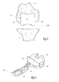
- la
figure 1 est une vue en élévation d'un genou à préparer, montrant l'extrémité inférieure d'un fémur et l'extrémité supérieure d'un tibia associé ; - la
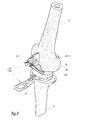
figure 2 est une vue en élévation similaire à lafigure 1 , montrant un bloc spécifique au patient appartenant à une instrumentation conforme à l'invention, en cours d'utilisation ; - la
figure 3 est une vue en élévation similaire à lafigure 2 , selon une direction opposée à cette dernière ; - la
figure 4 est une vue en perspective d'un organe d'espacement appartenant à l'instrumentation ; - la
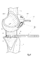
figure 5 est une vue en perspective montrant le bloc spécifique au patient dans une configuration subséquente à celle desfigures 2 et3 et associé à l'organe d'espacement de lafigure 4 ; - la
figure 6 est une vue similaire à lafigure 2 , illustrant le bloc spécifique au patient et l'organe d'espacement dans la configuration d'utilisation de lafigure 5 ; - la
figure 7 est une vue en élévation suivant la flèche VII de lafigure 6 ; et - les
figures 8 et9 sont des coupes selon respectivement la ligne VIII-VIII de lafigure 6 et la ligne IX-IX de lafigure 7 .
- the
figure 1 is an elevation view of a knee to be prepared, showing the lower end of a femur and the upper end of an associated tibia; - the
figure 2 is an elevation view similar to thefigure 1 , showing a patient-specific block belonging to an instrumentation according to the invention, in use; - the
figure 3 is an elevation view similar to thefigure 2 in a direction opposite to the latter; - the
figure 4 is a perspective view of a spacing member belonging to the instrumentation; - the
figure 5 is a perspective view showing the patient-specific block in a configuration subsequent to that of thefigures 2 and3 and associated with the spacing member of thefigure 4 ; - the
figure 6 is a view similar to thefigure 2 , illustrating the patient-specific block and the spacer in the use configuration of thefigure 5 ; - the
figure 7 is an elevation view along arrow VII of thefigure 6 ; and - the
figures 8 and9 are cuts along lines VIII-VIII of thefigure 6 and line IX-IX of thefigure 7 .
Sur la
Dans toute la suite de la description et, plus généralement, dans tout le présent document, les termes « supérieur », « inférieur », « vertical », « postérieur », etc. s'entendent dans leur sens anatomique usuel, en considérant que le patient opéré se tient debout sur une surface horizontale. Ainsi, la
Pour des raisons qui apparaîtront plus loin, on a représenté sur la
- une ligne référencée PS qui correspond à la trace, dans le plan frontal, du plan sagittal du genou,
- une ligne référencée PCD qui correspond à la trace, dans le plan frontal, du plan d'une coupe distale à venir de l'extrémité inférieure du fémur F,
- une ligne référencée PCT qui correspond à la trace, dans le plan frontal, du plan d'une coupe horizontale à venir de l'extrémité supérieure du tibia T, les plans PCD et PCT étant sensiblement parallèles lorsque le genou est en pleine extension et la balance ligamentaire du genou est équilibrée, et
- une ligne référencée LDC qui est une droite géométrique appartenant au plan frontal et passant par, à la fois, le sommet distal du condyle interne FI du fémur F et le sommet distal du condyle externe FE du fémur.
- a line referenced PS which corresponds to the trace, in the frontal plane, of the sagittal plane of the knee,
- a line referenced PCD which corresponds to the trace, in the frontal plane, of the plane of a distal section to come from the lower end of the femur F,
- a line referenced PCT which corresponds to the trace, in the frontal plane, of the plane of a future horizontal section of the upper end of the tibia T, the PCD and PCT planes being substantially parallel when the knee is in full extension and the ligament balance of the knee is balanced, and
- a line referenced LDC which is a geometrical line belonging to the frontal plane and passing through, at the same time, the distal vertex of the internal condyle FI of the femur F and the distal vertex of the external condyle FE of the femur.
Sur les
Préalablement à l'intervention chirurgicale d'implantation proprement dite, on recueille des données de cartographie relatives au genou du patient à opérer, en particulier relatives au fémur F. En pratique, ces données de cartographie préopératoires peuvent être obtenues de diverses manières. A titre d'exemple, des images scanner et/ou radiographiques et/ou échographiques et/ou d'IRM sont utilisées.Prior to actual implantation surgery, mapping data relating to the knee of the patient to be operated are collected, particularly relating to femur F. In practice, these preoperative mapping data can be obtained in a variety of ways. By way of example, scanner and / or radiographic and / or ultrasound and / or MRI images are used.
Dans tous les cas, à l'issue de cette étape préalable d'acquisition des données, on dispose de suffisamment d'informations pour concevoir et fabriquer un bloc fémoral 10 spécifique au patient, montré en position sur le fémur sur les
On notera que, dans le mode de réalisation considéré sur les figures, la surface d'appui 11 recouvre des zones de l'extrémité inférieure du fémur, qui sont situées de part et d'autre du plan sagittal PS, en épousant de manière ajustée les reliefs de ces zones. En particulier, la surface d'appui 11 recouvre des régions antérieures et distales du condyle interne FI, ainsi que des régions antérieures et distales du condyle externe FE, si bien que les sommets distaux de ces condyles, reliés par la ligne LDC, sont recouverts de manière ajustée par la surface 11. Ainsi, en d'autres termes, la surface d'appui 11 s'étend ici de part et d'autre du plan sagittal PS du genou de manière à coopérer avec les condyles interne et externe de l'extrémité du fémur F.Note that, in the embodiment considered in the figures, the bearing
En service, le bloc fémoral 10 est destiné à être appuyé fixement, par sa surface 11, sur l'extrémité inférieure du fémur F. Dans l'exemple de réalisation considéré, cette fixation est réalisée grâce à deux broches d'ancrage osseux 12 conçues pour être respectivement engagées de façon complémentaire dans des trous traversants qui relient chacun la face 10A du bloc fémoral à sa face opposée 10B, c'est-à-dire celle tournée vers le chirurgien. Les broches d'ancrage 12 sont ainsi engagées dans les trous traversants précités jusqu'à se planter et ainsi s'immobiliser dans la matière osseuse du fémur F.In use, the
Sur sa face 10B, le bloc fémoral 10 délimite une surface incurvée 13, bien visible sur les
Dans l'exemple de réalisation considéré sur les figures, cette surface incurvée 13 s'apparente grossièrement à une portion de surface cylindrique dont l'axe central Z13 s'étend de manière médio-latérale, étant remarqué que cette portion de surface cylindrique présente un étranglement médian, ce qui rend la surface 13 similaire à une portion de diabolo. Plus généralement, pour des raisons qui apparaîtront un peu plus loin, la surface incurvée 13 est prévue pour présenter, en tout plan perpendiculaire à l'axe Z13, un profil sensiblement en arc de cercle centré sur cet axe.In the exemplary embodiment considered in the figures, this
En revenant maintenant à la description de l'intervention chirurgicale au cours de laquelle l'instrumentation 1 est utilisée, une première étape de cette intervention consiste, après avoir dégagé les chairs molles entourant l'extrémité inférieure du fémur et l'extrémité supérieure du tibia, à réséquer l'extrémité supérieure du tibia T : ainsi, lorsqu'on passe de la
Dans un deuxième temps opératoire, le chirurgien fixe le bloc fémoral 10 sur l'extrémité inférieure du fémur F, moyennant l'appui ajusté de sa surface 11 sur cette extrémité inférieure du fémur comme expliqué en détail plus haut. Après mise en place des broches d'ancrage 12, le bloc fémoral 10 est tel que représenté sur les
Dans un troisième temps opératoire qui est illustré par les
En service, lorsque l'organe d'espacement 20 est interposé entre l'extrémité supérieure réséquée du tibia T et le bloc fémoral 10 fixé à l'extrémité inférieure du fémur F, les surfaces incurvées 13 et 26 sont prévues pour coopérer de sorte que leur mise en appui de manière ajustée l'une contre l'autre caractérise l'équilibre de la balance ligamentaire du genou pour la configuration de flexion-extension de ce dernier considérée, typiquement dans la configuration de pleine extension sur les
Si cette balance ligamentaire du genou en extension n'était pas équilibrée, les surfaces planes 13 et 26 ne seraient pas en appui jointif, mais, au contraire, s'écarteraient l'une de l'autre sur un des côtés interne et externe du genou. Bien entendu, si le chirurgien constate un défaut d'ajustement pour l'appui des surfaces 13 et 26 l'une contre l'autre, le chirurgien réalise des actes de correction de la balance ligamentaire, typiquement en relâchant la tension du ligament latéral interne ou celle du ligament latéral externe, jusqu'à faire sensiblement disparaître toute laxité résiduelle, ce qui s'observe par la fermeture du jour, externe ou interne, qui subsistait jusqu'alors entre les surfaces 13 et 26.If this ligamentary balance of the knee in extension was not balanced, the
Eu égard au profil en arc de cercle des surfaces complémentaires 13 et 26, on comprend que la configuration de flexion-extension du genou peut être continument modifiée entre sa configuration de pleine extension et sa configuration de flexion à 90°, voire au-delà de cette dernière, tout en maintenant l'appui ajusté entre les surfaces 13 et 26 lorsque la balance ligamentaire du genou ainsi entraînée reste équilibrée.With regard to the arcuate profile of the
Avantageusement, la forme en diabolo évoquée plus haut stabilise, suivant une direction médio-latérale, la coopération en rotation, autour de l'axe Z13, entre les surfaces 13 et 26.Advantageously, the diabolo form mentioned above stabilizes, in a mediolateral direction, the cooperation in rotation about the axis Z13, between the
Bien entendu, à titre de variante, la plage angulaire de flexion-extension du genou, pouvant être balayée pour vérifier l'équilibre de la balance ligamentaire du genou, peut être moins étendue que celle envisagée ci-dessus en regard des figures, moyennant un dimensionnement adéquat des surfaces incurvées 13 et 26 autour de leur axe de rotation relative Z13.Of course, as an alternative, the angular range of flexion-extension of the knee, which can be scanned to check the balance of the ligament balance of the knee, may be less extensive than that envisaged above with reference to the figures, with a adequate dimensioning of the
Par ailleurs, on comprend que le chirurgien a la possibilité de remplacer l'insert 25 utilisé par un insert ayant la même forme géométrique d'ensemble, à la différence que l'insert de remplacement présente une épaisseur différente de celle de l'insert précédemment utilisé lorsque le chirurgien constate que, avec l'insert précédemment utilisé, l'espace libre entre le bloc fémoral 10 fixé au fémur et l'extrémité réséquée du tibia est trop étroit pour y insérer l'organe d'espacement, ce qui traduit une trop forte épaisseur de l'insert précédemment utilisé, ou bien, au contraire, lorsque le chirurgien constate que, après mise en place de l'organe d'espacement 20, la totalité de la surface 26 reste distante de la totalité de la surface 13, ce qui traduit une trop faible épaisseur de l'insert précédemment utilisé. Sur la base des considérations qui précèdent, on comprend que, en fonction de l'insert 25 finalement retenu par le chirurgien pour lui permettre de contrôler l'équilibre de la balance ligamentaire, le chirurgien dispose d'une donnée dimensionnelle quant à l'écartement entre, d'une part, l'extrémité réséquée du tibia T et, d'autre part, le bloc fémoral 10 fixé au fémur F et donc, plus globalement, l'extrémité inférieure du fémur F eu égard au positionnement prédéterminé précis du bloc fémoral 10 sur le fémur F comme expliqué plus haut. Cette donnée dimensionnelle s'avère utile pour choisir le dimensionnement d'au moins certains des composant prothétiques de la prothèse de genou à implanter, ainsi que pour, le cas échéant, ajuster l'altitude du plan PCD et/ou abaisser l'altitude du plan PCT.Furthermore, it is understood that the surgeon has the possibility of replacing the
La suite de l'intervention chirurgicale, visant à implanter une prothèse de genou, ne sera pas détaillée dans la mesure où cet aspect n'est pas limitatif de la présente invention. On notera uniquement que, au cours de cette suite de l'intervention, l'extrémité inférieure du fémur F va être réséquée selon un plan de coupe distale, correspondant au plan PCD initialement envisagé ou à un plan parallèle situé à une hauteur différente par rapport au fémur, étant étendu que le plan dans lequel la coupe distale sera effectivement réalisée peut avantageusement être positionné avec précision grâce au bloc fémoral 10, par exemple en utilisant les broches d'ancrage 12 pour rapporter un bloc de coupe après avoir dégagé le bloc fémoral 10.The rest of the surgical procedure, aimed at implanting a knee prosthesis, will not be detailed to the extent that this aspect is not limiting of the present invention. Note only that during this continuation of the intervention, the lower end of the femur F will be resected in a distal sectional plane, corresponding to the PCD plane initially envisaged or a parallel plane located at a different height relative to the femur, being extended that the plane in which the distal section will be effectively performed can advantageously be accurately positioned thanks to the
Ainsi, grâce à l'instrumentation 1, le chirurgien peut, sur toute une plage continue de flexion-extension du genou, contrôler efficacement l'équilibre de la balance ligamentaire. En particulier, comme expliqué plus haut, la surface incurvée 26 ne coopère pas directement avec l'extrémité inférieure du fémur F, ce qui, dans le cas contraire, rendrait difficile le contrôle de l'équilibre interne-externe de la balance ligamentaire en raison de l'inclinaison non orthogonale de la ligne LDC par rapport au plan sagittal PS, mais cette surface plane 26 est en mesure de coopérer avec une surface géométrique de référence définie par la surface 13 du bloc fémoral 10 conçue en conséquence. Bien entendu, cela est obtenu sans que le chirurgien n'ait encore réséqué la région distale de l'extrémité inférieure du fémur, ce qui lui laisse, en fonction des conséquences potentielles liées au rééquilibrage de la balance ligamentaire du genou, la possibilité de modifier le long du fémur la hauteur à laquelle sera réalisée la coupe distale selon le plan PCD.Thus, thanks to the
Plus généralement, on comprend que la congruence rigoureuse des surfaces 13 et 26 permet de contrôler avec précision la balance ligamentaire dans toutes les configurations de flexion-extension entre les deux configurations extrêmes opposées précitées, en vérifiant l'espace entre le fémur et le tibia. A titre de variante, plutôt que d'être rigoureusement congruentes, les surfaces 13 et 26 peuvent être prédéterminées de manière à simuler l'interaction et la cinématique entre les composants d'une prothèse de genou à implanter : dans ce cas, ces surfaces s'articulent l'une sur l'autre lors de la flexion du genou, en s'appuyant l'une contre l'autre de manière sensiblement mais non rigoureusement ajustée, et ce de manière suffisante pour permettre un contrôle satisfaisant de la balance ligamentaire, tout en permettant de vérifier la cinématique de coopération entre ces surfaces.More generally, it will be understood that the rigorous congruence of the
Par ailleurs, dans les deux modes de réalisation évoqués juste ci-dessus, un aménagement optionnel consiste en ce que des moyens de mesure, tels que des capteurs de pression, des accéléromètres, des gyromètres, etc, sont intégrés à l'instrumentation pour caractériser et/ou quantifier la balance ligamentaire et/ou la cinématique de coopération entre les surfaces 13 et 26.Moreover, in the two embodiments mentioned just above, an optional arrangement consists in that measurement means, such as pressure sensors, accelerometers, gyrometers, etc., are integrated into the instrumentation to characterize and / or quantifying the ligament balance and / or the kinematics of cooperation between the
Divers aménagements et variantes à l'instrumentation 1 décrite jusqu'ici sont par ailleurs envisageables. A titre d'exemples :
- en variante non représentée, l'instrumentation peut être prévue unicompartimentale, c'est-à-dire que le bloc fémoral et l'organe d'espacement sont alors dimensionnés pour n'être utilisés qu'au niveau d'un seul des compartiments interne et externe du genou, étant entendu que, dans ce cas, cette instrumentation est particulièrement adaptée à la préparation du genou d'un patient en vue d'y implanter une prothèse totale unicompartimentale ;
- plutôt que de prévoir un bloc spécifique au patient à fixer au fémur, une solution « miroir » consiste à prévoir un bloc spécifique au patient à fixer à l'extrémité supérieure non réséquée du tibia T, autrement dit un bloc tibial spécifique au patient, étant entendu que, dans ce cas, d'une part, l'utilisation de l'instrumentation nécessite de commencer par une résection de l'extrémité inférieure du fémur et, d'autre part, cette instrumentation comprend un organe d'espacement à interposer entre l'extrémité inférieure réséquée du fémur et le bloc tibial précité, fixé à l'extrémité supérieure du tibia ; et/ou
- plutôt que d'être réalisé sous forme monolithique, comme c'est le cas pour
le bloc fémoral 10 considéré sur les figures, le bloc spécifique au patient appartenant à l'instrumentation conforme à l'invention peut être réalisé en deux matériaux différents, en particulier pour ce qui concerne le corps principal de ce bloc spécifique au patient, tel que le corps principal 15 pourle bloc fémoral 10 ; ainsi, le bloc spécifique au patient inclut une première partie réalisée en un premier matériau, qui porte la surface d'appui fixe sur le fémur ou le tibia, ce premier matériau étant typiquement une matière plastique pour des raisons de facilité de fabrication de cette première partie ; et le bloc spécifique au patient inclut en outre une seconde partie solidaire de la première partie, qui porte la ou les surfaces libres, telles que lasurface 13de l'instrumentation 1, et qui est réalisée en un autre matériau que celui de la première partie, en prévoyant que cet autre matériau permet un bon glissement à l'interface de contact entre la ou les surfaces libres précitées et la surface complémentaire de l'organe d'espacement ; une telle option de fabrication trouve un intérêt particulier pour le mode de réalisation de l'instrumentation 1 en raison de la mobilité rotative entre lebloc 10 et l'organe d'espacement 20.
- alternatively not shown, the instrumentation may be provided unicompartimentale, that is to say that the femoral block and the spacing member are then dimensioned to be used at only one of the internal compartments and external of the knee, it being understood that, in this case, this instrumentation is particularly adapted to the preparation of the knee of a patient in order to implant a total unicompartmental prosthesis;
- rather than providing a patient specific block to be attached to the femur, a "mirror" solution is to provide a patient-specific block to attach to the unresected upper end of the tibia T, ie a patient-specific tibial block, being understood that, in this case, on the one hand, the use of the instrumentation requires starting with a resection of the lower end of the femur and, secondly, this instrumentation comprises a spacing member to interpose between the resected lower end of the femur and the aforementioned tibial block attached to the upper end of the tibia; and or
- rather than being realized in monolithic form, as is the case for the
femoral block 10 considered in the figures, the patient-specific block belonging to the instrumentation according to the invention can be made of two different materials, particularly with respect to the main body of this patient-specific block, such as the main body 15 for thefemoral block 10; thus, the patient-specific block includes a first portion made of a first material, which carries the fixed bearing surface on the femur or the tibia, this first material being typically a plastic material for reasons of ease of manufacture of this first part ; and the patient-specific block further includes a second integral portion of the first portion, which carries the at least one free surface, such as thesurface 13 of theinstrumentation 1, and which is made of a material other than that of the first part, providing that this other material allows good sliding to the contact interface between the aforementioned free surface (s) and the complementary surface of the spacer member; such a manufacturing option is of particular interest for the embodiment of theinstrumentation 1 because of the rotational mobility between theblock 10 and the spacingmember 20.
Claims (8)
caractérisée en ce que la surface libre (13) du bloc spécifique au patient (10) est incurvée de manière que cette surface libre et la surface de coopération (26) de l'organe d'espacement (20) sont adaptées pour s'appuyer de manière sensiblement ajustée l'une contre l'autre lorsque la balance ligamentaire du genou est équilibrée pendant que le genou est passé d'une configuration de flexion-extension à une autre configuration de flexion-extension.
characterized in that the free surface (13) of the particular block to the patient (10) is curved so that the free surface and the engagement surface (26) of the spacer member (20) are adapted to support substantially adjusted against each other when the ligament balance of the knee is balanced while the knee has moved from a flexion-extension configuration to another flexion-extension configuration.
Applications Claiming Priority (1)
| Application Number | Priority Date | Filing Date | Title |
|---|---|---|---|
| FR1256601A FR2992850A1 (en) | 2012-07-09 | 2012-07-09 | PATIENT-SPECIFIC SURGICAL INSTRUMENTATION FOR THE PREPARATION OF THE PATIENT KNEE |
Publications (2)
| Publication Number | Publication Date |
|---|---|
| EP2684544A1 true EP2684544A1 (en) | 2014-01-15 |
| EP2684544B1 EP2684544B1 (en) | 2015-01-21 |
Family
ID=48700485
Family Applications (1)
| Application Number | Title | Priority Date | Filing Date |
|---|---|---|---|
| EP20130175368 Not-in-force EP2684544B1 (en) | 2012-07-09 | 2013-07-05 | Patient-specific surgical instrument for preparing the knee of the patient |
Country Status (2)
| Country | Link |
|---|---|
| EP (1) | EP2684544B1 (en) |
| FR (1) | FR2992850A1 (en) |
Citations (4)
| Publication number | Priority date | Publication date | Assignee | Title |
|---|---|---|---|---|
| WO2007036699A1 (en) * | 2005-09-30 | 2007-04-05 | Depuy International Limited | A distractor instrument |
| US20090087276A1 (en) * | 2007-09-30 | 2009-04-02 | Bryan Rose | Apparatus and Method for Fabricating a Customized Patient-Specific Orthopaedic Instrument |
| US20100212138A1 (en) * | 2009-02-24 | 2010-08-26 | Wright Medical Technology, Inc. | Method For Forming A Patient Specific Surgical Guide Mount |
| WO2012024306A2 (en) * | 2010-08-16 | 2012-02-23 | Aashiish Agnihotri | Surgical guides |
-
2012
- 2012-07-09 FR FR1256601A patent/FR2992850A1/en active Pending
-
2013
- 2013-07-05 EP EP20130175368 patent/EP2684544B1/en not_active Not-in-force
Patent Citations (4)
| Publication number | Priority date | Publication date | Assignee | Title |
|---|---|---|---|---|
| WO2007036699A1 (en) * | 2005-09-30 | 2007-04-05 | Depuy International Limited | A distractor instrument |
| US20090087276A1 (en) * | 2007-09-30 | 2009-04-02 | Bryan Rose | Apparatus and Method for Fabricating a Customized Patient-Specific Orthopaedic Instrument |
| US20100212138A1 (en) * | 2009-02-24 | 2010-08-26 | Wright Medical Technology, Inc. | Method For Forming A Patient Specific Surgical Guide Mount |
| WO2012024306A2 (en) * | 2010-08-16 | 2012-02-23 | Aashiish Agnihotri | Surgical guides |
Also Published As
| Publication number | Publication date |
|---|---|
| EP2684544B1 (en) | 2015-01-21 |
| FR2992850A1 (en) | 2014-01-10 |
Similar Documents
| Publication | Publication Date | Title |
|---|---|---|
| EP1732448B1 (en) | Ancillary assembly for implanting a knee prosthesis | |
| EP1813230B1 (en) | Chirurgical instumentation kit for placing a dowel prosthesis. | |
| EP2589354B1 (en) | Surgical instrument assembly for inserting an ankle prosthesis | |
| EP2277460A1 (en) | Surgical instrumentation for preparing the setting of a knee prosthesis | |
| EP1712192B1 (en) | Surgical device for implanting a partial or total knee prosthesis | |
| EP1643916B1 (en) | Device for assisting in total knee prosthesis implantation | |
| FR2955250A1 (en) | SURGICAL ASSISTANCE ASSEMBLY FOR THE IMPLANTATION OF A GLENOIDAL COMPONENT OF SHOULDER PROSTHESIS | |
| EP1712193A1 (en) | Surgical device for implanting a partial or total knee prosthesis | |
| WO2010023399A1 (en) | Set of ancillaries for implanting a knee prosthesis | |
| EP1915975B1 (en) | Ankle prosthesis with neutral position adjustment | |
| WO2005018509A2 (en) | Device for dynamic tensioning of a natural or prosthetic knee joint | |
| FR2635675A1 (en) | Accessory instrumentation for implanting a total knee prosthesis and secondarily for axial correction osteotomies | |
| WO2016012731A1 (en) | Surgical device to assist with placement of an orthopedic implant between two bones of a joint of a patient | |
| FR2949315A1 (en) | Surgical instrument for positioning knee prosthesis during orthopedic knee operation, has assembly including centro-medullary rod and interfacing unit to cooperate with another interfacing unit so as to create removable link | |
| EP2684544B1 (en) | Patient-specific surgical instrument for preparing the knee of the patient | |
| EP2687189B1 (en) | Interpositional trapezium implant | |
| FR2938178A1 (en) | Osseous preparation accessory for femur of patient to receive prosthetic femoral component of knee prosthesis, has positioning and orientation units comprising predetermined gaps along direction perpendicular to distal cutting plane | |
| FR2945436A1 (en) | SURGICAL INSTRUMENTATION OF BONE DISTRACTION OF THE SHOULDER | |
| EP2685916B1 (en) | Patient-specific surgical instrumentation for preparing the patient's femur | |
| FR2979056A1 (en) | PATIENT-SPECIFIC SURGICAL INSTRUMENTATION FOR PREPARING THE KNEE OF THIS PATIENT | |
| FR2829376A1 (en) | Knee joint arthroplasty cutting line marker has femoral and tibial instruments with assembly system | |
| FR3022764A1 (en) | GUIDE FOR BEING POSITIONED ON A BONE OF A JOINT TO BE OPERATED, METHOD OF MANUFACTURING THE SAME AND METHODS OF SURGICAL OPERATION USING THE SAME | |
| FR2966342A1 (en) | Resurfacing femoral implant assembly for e.g. strickle to install unicompartmental knee prosthesis, has implants with same radius, where distance between axis and face is same for all implants such that implants are anchored at femur end | |
| FR2883724A1 (en) | Ancilliary instrument for optimally positioning a rod-form joint prosthesis in long bone, e.g. the femur, comprises mutually movable elements for transferring position of trial prosthesis to final prosthesis | |
| EP2617394B1 (en) | Tibial implant for a unicompartmental knee prosthesis |
Legal Events
| Date | Code | Title | Description |
|---|---|---|---|
| PUAI | Public reference made under article 153(3) epc to a published international application that has entered the european phase |
Free format text: ORIGINAL CODE: 0009012 |
|
| AK | Designated contracting states |
Kind code of ref document: A1 Designated state(s): AL AT BE BG CH CY CZ DE DK EE ES FI FR GB GR HR HU IE IS IT LI LT LU LV MC MK MT NL NO PL PT RO RS SE SI SK SM TR |
|
| AX | Request for extension of the european patent |
Extension state: BA ME |
|
| 17P | Request for examination filed |
Effective date: 20140617 |
|
| RBV | Designated contracting states (corrected) |
Designated state(s): AL AT BE BG CH CY CZ DE DK EE ES FI FR GB GR HR HU IE IS IT LI LT LU LV MC MK MT NL NO PL PT RO RS SE SI SK SM TR |
|
| GRAP | Despatch of communication of intention to grant a patent |
Free format text: ORIGINAL CODE: EPIDOSNIGR1 |
|
| INTG | Intention to grant announced |
Effective date: 20140829 |
|
| GRAS | Grant fee paid |
Free format text: ORIGINAL CODE: EPIDOSNIGR3 |
|
| GRAA | (expected) grant |
Free format text: ORIGINAL CODE: 0009210 |
|
| AK | Designated contracting states |
Kind code of ref document: B1 Designated state(s): AL AT BE BG CH CY CZ DE DK EE ES FI FR GB GR HR HU IE IS IT LI LT LU LV MC MK MT NL NO PL PT RO RS SE SI SK SM TR |
|
| REG | Reference to a national code |
Ref country code: GB Ref legal event code: FG4D Free format text: NOT ENGLISH |
|
| REG | Reference to a national code |
Ref country code: CH Ref legal event code: EP |
|
| REG | Reference to a national code |
Ref country code: IE Ref legal event code: FG4D Free format text: LANGUAGE OF EP DOCUMENT: FRENCH |
|
| REG | Reference to a national code |
Ref country code: DE Ref legal event code: R096 Ref document number: 602013000877 Country of ref document: DE Effective date: 20150305 |
|
| REG | Reference to a national code |
Ref country code: AT Ref legal event code: REF Ref document number: 708810 Country of ref document: AT Kind code of ref document: T Effective date: 20150315 |
|
| REG | Reference to a national code |
Ref country code: NL Ref legal event code: VDEP Effective date: 20150121 |
|
| REG | Reference to a national code |
Ref country code: AT Ref legal event code: MK05 Ref document number: 708810 Country of ref document: AT Kind code of ref document: T Effective date: 20150121 |
|
| REG | Reference to a national code |
Ref country code: LT Ref legal event code: MG4D |
|
| PG25 | Lapsed in a contracting state [announced via postgrant information from national office to epo] |
Ref country code: BG Free format text: LAPSE BECAUSE OF FAILURE TO SUBMIT A TRANSLATION OF THE DESCRIPTION OR TO PAY THE FEE WITHIN THE PRESCRIBED TIME-LIMIT Effective date: 20150421 Ref country code: NO Free format text: LAPSE BECAUSE OF FAILURE TO SUBMIT A TRANSLATION OF THE DESCRIPTION OR TO PAY THE FEE WITHIN THE PRESCRIBED TIME-LIMIT Effective date: 20150421 Ref country code: LT Free format text: LAPSE BECAUSE OF FAILURE TO SUBMIT A TRANSLATION OF THE DESCRIPTION OR TO PAY THE FEE WITHIN THE PRESCRIBED TIME-LIMIT Effective date: 20150121 Ref country code: ES Free format text: LAPSE BECAUSE OF FAILURE TO SUBMIT A TRANSLATION OF THE DESCRIPTION OR TO PAY THE FEE WITHIN THE PRESCRIBED TIME-LIMIT Effective date: 20150121 Ref country code: HR Free format text: LAPSE BECAUSE OF FAILURE TO SUBMIT A TRANSLATION OF THE DESCRIPTION OR TO PAY THE FEE WITHIN THE PRESCRIBED TIME-LIMIT Effective date: 20150121 Ref country code: FI Free format text: LAPSE BECAUSE OF FAILURE TO SUBMIT A TRANSLATION OF THE DESCRIPTION OR TO PAY THE FEE WITHIN THE PRESCRIBED TIME-LIMIT Effective date: 20150121 Ref country code: SE Free format text: LAPSE BECAUSE OF FAILURE TO SUBMIT A TRANSLATION OF THE DESCRIPTION OR TO PAY THE FEE WITHIN THE PRESCRIBED TIME-LIMIT Effective date: 20150121 |
|
| PG25 | Lapsed in a contracting state [announced via postgrant information from national office to epo] |
Ref country code: RS Free format text: LAPSE BECAUSE OF FAILURE TO SUBMIT A TRANSLATION OF THE DESCRIPTION OR TO PAY THE FEE WITHIN THE PRESCRIBED TIME-LIMIT Effective date: 20150121 Ref country code: LV Free format text: LAPSE BECAUSE OF FAILURE TO SUBMIT A TRANSLATION OF THE DESCRIPTION OR TO PAY THE FEE WITHIN THE PRESCRIBED TIME-LIMIT Effective date: 20150121 Ref country code: NL Free format text: LAPSE BECAUSE OF FAILURE TO SUBMIT A TRANSLATION OF THE DESCRIPTION OR TO PAY THE FEE WITHIN THE PRESCRIBED TIME-LIMIT Effective date: 20150121 Ref country code: AT Free format text: LAPSE BECAUSE OF FAILURE TO SUBMIT A TRANSLATION OF THE DESCRIPTION OR TO PAY THE FEE WITHIN THE PRESCRIBED TIME-LIMIT Effective date: 20150121 Ref country code: IS Free format text: LAPSE BECAUSE OF FAILURE TO SUBMIT A TRANSLATION OF THE DESCRIPTION OR TO PAY THE FEE WITHIN THE PRESCRIBED TIME-LIMIT Effective date: 20150521 Ref country code: GR Free format text: LAPSE BECAUSE OF FAILURE TO SUBMIT A TRANSLATION OF THE DESCRIPTION OR TO PAY THE FEE WITHIN THE PRESCRIBED TIME-LIMIT Effective date: 20150422 Ref country code: PL Free format text: LAPSE BECAUSE OF FAILURE TO SUBMIT A TRANSLATION OF THE DESCRIPTION OR TO PAY THE FEE WITHIN THE PRESCRIBED TIME-LIMIT Effective date: 20150121 |
|
| REG | Reference to a national code |
Ref country code: DE Ref legal event code: R097 Ref document number: 602013000877 Country of ref document: DE |
|
| PG25 | Lapsed in a contracting state [announced via postgrant information from national office to epo] |
Ref country code: CZ Free format text: LAPSE BECAUSE OF FAILURE TO SUBMIT A TRANSLATION OF THE DESCRIPTION OR TO PAY THE FEE WITHIN THE PRESCRIBED TIME-LIMIT Effective date: 20150121 Ref country code: EE Free format text: LAPSE BECAUSE OF FAILURE TO SUBMIT A TRANSLATION OF THE DESCRIPTION OR TO PAY THE FEE WITHIN THE PRESCRIBED TIME-LIMIT Effective date: 20150121 Ref country code: SK Free format text: LAPSE BECAUSE OF FAILURE TO SUBMIT A TRANSLATION OF THE DESCRIPTION OR TO PAY THE FEE WITHIN THE PRESCRIBED TIME-LIMIT Effective date: 20150121 Ref country code: RO Free format text: LAPSE BECAUSE OF FAILURE TO SUBMIT A TRANSLATION OF THE DESCRIPTION OR TO PAY THE FEE WITHIN THE PRESCRIBED TIME-LIMIT Effective date: 20150121 Ref country code: DK Free format text: LAPSE BECAUSE OF FAILURE TO SUBMIT A TRANSLATION OF THE DESCRIPTION OR TO PAY THE FEE WITHIN THE PRESCRIBED TIME-LIMIT Effective date: 20150121 |
|
| PLBE | No opposition filed within time limit |
Free format text: ORIGINAL CODE: 0009261 |
|
| STAA | Information on the status of an ep patent application or granted ep patent |
Free format text: STATUS: NO OPPOSITION FILED WITHIN TIME LIMIT |
|
| 26N | No opposition filed |
Effective date: 20151022 |
|
| PG25 | Lapsed in a contracting state [announced via postgrant information from national office to epo] |
Ref country code: SI Free format text: LAPSE BECAUSE OF FAILURE TO SUBMIT A TRANSLATION OF THE DESCRIPTION OR TO PAY THE FEE WITHIN THE PRESCRIBED TIME-LIMIT Effective date: 20150121 Ref country code: MC Free format text: LAPSE BECAUSE OF FAILURE TO SUBMIT A TRANSLATION OF THE DESCRIPTION OR TO PAY THE FEE WITHIN THE PRESCRIBED TIME-LIMIT Effective date: 20150121 |
|
| PG25 | Lapsed in a contracting state [announced via postgrant information from national office to epo] |
Ref country code: LU Free format text: LAPSE BECAUSE OF FAILURE TO SUBMIT A TRANSLATION OF THE DESCRIPTION OR TO PAY THE FEE WITHIN THE PRESCRIBED TIME-LIMIT Effective date: 20150705 |
|
| REG | Reference to a national code |
Ref country code: IE Ref legal event code: MM4A |
|
| REG | Reference to a national code |
Ref country code: FR Ref legal event code: PLFP Year of fee payment: 4 |
|
| PG25 | Lapsed in a contracting state [announced via postgrant information from national office to epo] |
Ref country code: IE Free format text: LAPSE BECAUSE OF NON-PAYMENT OF DUE FEES Effective date: 20150705 |
|
| REG | Reference to a national code |
Ref country code: DE Ref legal event code: R082 Ref document number: 602013000877 Country of ref document: DE Representative=s name: LAVOIX MUNICH, DE Ref country code: DE Ref legal event code: R082 Ref document number: 602013000877 Country of ref document: DE Representative=s name: BECKER-KURIG-STRAUS PATENTANWAELTE PARTNERSCHA, DE Ref country code: DE Ref legal event code: R082 Ref document number: 602013000877 Country of ref document: DE Representative=s name: BECKER & KURIG PARTNERSCHAFT PATENTANWAELTE MB, DE Ref country code: DE Ref legal event code: R082 Ref document number: 602013000877 Country of ref document: DE Representative=s name: BECKER & KURIG PARTNERSCHAFT PATENTANWAELTE PA, DE Ref country code: DE Ref legal event code: R082 Ref document number: 602013000877 Country of ref document: DE Representative=s name: BECKER, KURIG, STRAUS, DE Ref country code: DE Ref legal event code: R081 Ref document number: 602013000877 Country of ref document: DE Owner name: CORIN LTD., CIRENCESTER, GB Free format text: FORMER OWNER: TORNIER, MONTBONNOT-SAINT-MARTIN, FR Ref country code: DE Ref legal event code: R081 Ref document number: 602013000877 Country of ref document: DE Owner name: CORIN LIMITED, CIRENCESTER, GB Free format text: FORMER OWNER: TORNIER, MONTBONNOT-SAINT-MARTIN, FR |
|
| REG | Reference to a national code |
Ref country code: GB Ref legal event code: 732E Free format text: REGISTERED BETWEEN 20170119 AND 20170125 |
|
| REG | Reference to a national code |
Ref country code: DE Ref legal event code: R082 Ref document number: 602013000877 Country of ref document: DE Representative=s name: BECKER, KURIG, STRAUS, DE Ref country code: DE Ref legal event code: R082 Ref document number: 602013000877 Country of ref document: DE Ref country code: DE Ref legal event code: R082 Ref document number: 602013000877 Country of ref document: DE Representative=s name: BECKER-KURIG-STRAUS PATENTANWAELTE PARTNERSCHA, DE Ref country code: DE Ref legal event code: R082 Ref document number: 602013000877 Country of ref document: DE Representative=s name: BECKER & KURIG PARTNERSCHAFT PATENTANWAELTE MB, DE Ref country code: DE Ref legal event code: R082 Ref document number: 602013000877 Country of ref document: DE Representative=s name: BECKER & KURIG PARTNERSCHAFT PATENTANWAELTE PA, DE |
|
| PG25 | Lapsed in a contracting state [announced via postgrant information from national office to epo] |
Ref country code: MT Free format text: LAPSE BECAUSE OF FAILURE TO SUBMIT A TRANSLATION OF THE DESCRIPTION OR TO PAY THE FEE WITHIN THE PRESCRIBED TIME-LIMIT Effective date: 20150121 |
|
| REG | Reference to a national code |
Ref country code: CH Ref legal event code: NV Representative=s name: VENI GMBH, CH Ref country code: CH Ref legal event code: PUE Owner name: CORIN LIMITED, GB Free format text: FORMER OWNER: TORNIER, FR |
|
| PG25 | Lapsed in a contracting state [announced via postgrant information from national office to epo] |
Ref country code: HU Free format text: LAPSE BECAUSE OF FAILURE TO SUBMIT A TRANSLATION OF THE DESCRIPTION OR TO PAY THE FEE WITHIN THE PRESCRIBED TIME-LIMIT; INVALID AB INITIO Effective date: 20130705 |
|
| PG25 | Lapsed in a contracting state [announced via postgrant information from national office to epo] |
Ref country code: CY Free format text: LAPSE BECAUSE OF FAILURE TO SUBMIT A TRANSLATION OF THE DESCRIPTION OR TO PAY THE FEE WITHIN THE PRESCRIBED TIME-LIMIT Effective date: 20150121 |
|
| REG | Reference to a national code |
Ref country code: FR Ref legal event code: TP Owner name: CORIN LIMITED, GB Effective date: 20170619 |
|
| REG | Reference to a national code |
Ref country code: FR Ref legal event code: PLFP Year of fee payment: 5 |
|
| PG25 | Lapsed in a contracting state [announced via postgrant information from national office to epo] |
Ref country code: BE Free format text: LAPSE BECAUSE OF NON-PAYMENT OF DUE FEES Effective date: 20150731 |
|
| REG | Reference to a national code |
Ref country code: DE Ref legal event code: R082 Ref document number: 602013000877 Country of ref document: DE Representative=s name: BECKER-KURIG-STRAUS PATENTANWAELTE PARTNERSCHA, DE Ref country code: DE Ref legal event code: R082 Ref document number: 602013000877 Country of ref document: DE Representative=s name: BECKER & KURIG PARTNERSCHAFT PATENTANWAELTE MB, DE Ref country code: DE Ref legal event code: R082 Ref document number: 602013000877 Country of ref document: DE Representative=s name: BECKER & KURIG PARTNERSCHAFT PATENTANWAELTE PA, DE Ref country code: DE Ref legal event code: R082 Ref document number: 602013000877 Country of ref document: DE Representative=s name: BECKER, KURIG, STRAUS, DE Ref country code: DE Ref legal event code: R081 Ref document number: 602013000877 Country of ref document: DE Owner name: CORIN LIMITED, CIRENCESTER, GB Free format text: FORMER OWNER: CORIN LTD., CIRENCESTER, GLOUCESTERSHIRE, GB |
|
| PG25 | Lapsed in a contracting state [announced via postgrant information from national office to epo] |
Ref country code: SM Free format text: LAPSE BECAUSE OF FAILURE TO SUBMIT A TRANSLATION OF THE DESCRIPTION OR TO PAY THE FEE WITHIN THE PRESCRIBED TIME-LIMIT Effective date: 20150121 |
|
| PG25 | Lapsed in a contracting state [announced via postgrant information from national office to epo] |
Ref country code: MK Free format text: LAPSE BECAUSE OF FAILURE TO SUBMIT A TRANSLATION OF THE DESCRIPTION OR TO PAY THE FEE WITHIN THE PRESCRIBED TIME-LIMIT Effective date: 20150121 Ref country code: PT Free format text: LAPSE BECAUSE OF FAILURE TO SUBMIT A TRANSLATION OF THE DESCRIPTION OR TO PAY THE FEE WITHIN THE PRESCRIBED TIME-LIMIT Effective date: 20150121 Ref country code: TR Free format text: LAPSE BECAUSE OF FAILURE TO SUBMIT A TRANSLATION OF THE DESCRIPTION OR TO PAY THE FEE WITHIN THE PRESCRIBED TIME-LIMIT Effective date: 20150121 |
|
| REG | Reference to a national code |
Ref country code: FR Ref legal event code: PLFP Year of fee payment: 6 |
|
| PG25 | Lapsed in a contracting state [announced via postgrant information from national office to epo] |
Ref country code: AL Free format text: LAPSE BECAUSE OF FAILURE TO SUBMIT A TRANSLATION OF THE DESCRIPTION OR TO PAY THE FEE WITHIN THE PRESCRIBED TIME-LIMIT Effective date: 20150121 |
|
| PGFP | Annual fee paid to national office [announced via postgrant information from national office to epo] |
Ref country code: FR Payment date: 20190731 Year of fee payment: 7 Ref country code: IT Payment date: 20190730 Year of fee payment: 7 Ref country code: DE Payment date: 20190730 Year of fee payment: 7 |
|
| PGFP | Annual fee paid to national office [announced via postgrant information from national office to epo] |
Ref country code: GB Payment date: 20190726 Year of fee payment: 7 |
|
| PGFP | Annual fee paid to national office [announced via postgrant information from national office to epo] |
Ref country code: CH Payment date: 20190821 Year of fee payment: 7 |
|
| REG | Reference to a national code |
Ref country code: DE Ref legal event code: R119 Ref document number: 602013000877 Country of ref document: DE |
|
| REG | Reference to a national code |
Ref country code: CH Ref legal event code: PL |
|
| GBPC | Gb: european patent ceased through non-payment of renewal fee |
Effective date: 20200705 |
|
| PG25 | Lapsed in a contracting state [announced via postgrant information from national office to epo] |
Ref country code: LI Free format text: LAPSE BECAUSE OF NON-PAYMENT OF DUE FEES Effective date: 20200731 Ref country code: CH Free format text: LAPSE BECAUSE OF NON-PAYMENT OF DUE FEES Effective date: 20200731 Ref country code: GB Free format text: LAPSE BECAUSE OF NON-PAYMENT OF DUE FEES Effective date: 20200705 Ref country code: FR Free format text: LAPSE BECAUSE OF NON-PAYMENT OF DUE FEES Effective date: 20200731 |
|
| PG25 | Lapsed in a contracting state [announced via postgrant information from national office to epo] |
Ref country code: DE Free format text: LAPSE BECAUSE OF NON-PAYMENT OF DUE FEES Effective date: 20210202 |
|
| PG25 | Lapsed in a contracting state [announced via postgrant information from national office to epo] |
Ref country code: IT Free format text: LAPSE BECAUSE OF NON-PAYMENT OF DUE FEES Effective date: 20200705 |