EP2679213A2 - System and method for delivering air through a boom assembly - Google Patents
System and method for delivering air through a boom assembly Download PDFInfo
- Publication number
- EP2679213A2 EP2679213A2 EP13170380.3A EP13170380A EP2679213A2 EP 2679213 A2 EP2679213 A2 EP 2679213A2 EP 13170380 A EP13170380 A EP 13170380A EP 2679213 A2 EP2679213 A2 EP 2679213A2
- Authority
- EP
- European Patent Office
- Prior art keywords
- air
- equipment
- boom assembly
- assembly
- air delivery
- Prior art date
- Legal status (The legal status is an assumption and is not a legal conclusion. Google has not performed a legal analysis and makes no representation as to the accuracy of the status listed.)
- Withdrawn
Links
- 238000000034 method Methods 0.000 title claims description 13
- 238000004891 communication Methods 0.000 claims abstract description 19
- 239000000463 material Substances 0.000 claims description 7
- 239000012530 fluid Substances 0.000 claims description 5
- 230000005465 channeling Effects 0.000 claims description 2
- 230000000712 assembly Effects 0.000 description 4
- 238000000429 assembly Methods 0.000 description 4
- 239000000356 contaminant Substances 0.000 description 2
- 238000003384 imaging method Methods 0.000 description 2
- 239000002184 metal Substances 0.000 description 2
- 229940074731 ophthalmologic surgical aids Drugs 0.000 description 2
- 239000004033 plastic Substances 0.000 description 2
- 239000000853 adhesive Substances 0.000 description 1
- 230000001070 adhesive effect Effects 0.000 description 1
- 230000002411 adverse Effects 0.000 description 1
- 230000000903 blocking effect Effects 0.000 description 1
- 238000010276 construction Methods 0.000 description 1
- 238000001816 cooling Methods 0.000 description 1
- 238000002059 diagnostic imaging Methods 0.000 description 1
- 230000007717 exclusion Effects 0.000 description 1
- 230000006870 function Effects 0.000 description 1
- 238000010438 heat treatment Methods 0.000 description 1
- 238000012986 modification Methods 0.000 description 1
- 230000004048 modification Effects 0.000 description 1
- 238000001356 surgical procedure Methods 0.000 description 1
- 238000009423 ventilation Methods 0.000 description 1
- 239000011800 void material Substances 0.000 description 1
Images


Classifications
-
- F—MECHANICAL ENGINEERING; LIGHTING; HEATING; WEAPONS; BLASTING
- F24—HEATING; RANGES; VENTILATING
- F24F—AIR-CONDITIONING; AIR-HUMIDIFICATION; VENTILATION; USE OF AIR CURRENTS FOR SCREENING
- F24F13/00—Details common to, or for air-conditioning, air-humidification, ventilation or use of air currents for screening
- F24F13/02—Ducting arrangements
- F24F13/06—Outlets for directing or distributing air into rooms or spaces, e.g. ceiling air diffuser
- F24F13/078—Outlets for directing or distributing air into rooms or spaces, e.g. ceiling air diffuser combined with lighting fixtures
-
- A—HUMAN NECESSITIES
- A61—MEDICAL OR VETERINARY SCIENCE; HYGIENE
- A61G—TRANSPORT, PERSONAL CONVEYANCES, OR ACCOMMODATION SPECIALLY ADAPTED FOR PATIENTS OR DISABLED PERSONS; OPERATING TABLES OR CHAIRS; CHAIRS FOR DENTISTRY; FUNERAL DEVICES
- A61G12/00—Accommodation for nursing, e.g. in hospitals, not covered by groups A61G1/00 - A61G11/00, e.g. trolleys for transport of medicaments or food; Prescription lists
- A61G12/002—Supply appliances, e.g. columns for gas, fluid, electricity supply
- A61G12/004—Supply appliances, e.g. columns for gas, fluid, electricity supply mounted on the ceiling
-
- A—HUMAN NECESSITIES
- A61—MEDICAL OR VETERINARY SCIENCE; HYGIENE
- A61G—TRANSPORT, PERSONAL CONVEYANCES, OR ACCOMMODATION SPECIALLY ADAPTED FOR PATIENTS OR DISABLED PERSONS; OPERATING TABLES OR CHAIRS; CHAIRS FOR DENTISTRY; FUNERAL DEVICES
- A61G13/00—Operating tables; Auxiliary appliances therefor
- A61G13/10—Parts, details or accessories
- A61G13/108—Means providing sterile air at a surgical operation table or area
-
- F—MECHANICAL ENGINEERING; LIGHTING; HEATING; WEAPONS; BLASTING
- F24—HEATING; RANGES; VENTILATING
- F24F—AIR-CONDITIONING; AIR-HUMIDIFICATION; VENTILATION; USE OF AIR CURRENTS FOR SCREENING
- F24F3/00—Air-conditioning systems in which conditioned primary air is supplied from one or more central stations to distributing units in the rooms or spaces where it may receive secondary treatment; Apparatus specially designed for such systems
- F24F3/12—Air-conditioning systems in which conditioned primary air is supplied from one or more central stations to distributing units in the rooms or spaces where it may receive secondary treatment; Apparatus specially designed for such systems characterised by the treatment of the air otherwise than by heating and cooling
- F24F3/16—Air-conditioning systems in which conditioned primary air is supplied from one or more central stations to distributing units in the rooms or spaces where it may receive secondary treatment; Apparatus specially designed for such systems characterised by the treatment of the air otherwise than by heating and cooling by purification, e.g. by filtering; by sterilisation; by ozonisation
- F24F3/163—Clean air work stations, i.e. selected areas within a space which filtered air is passed
Definitions
- Embodiments generally relate to a system and method for delivering filtered air within a clean environment, and, more particularly, to a system and method for delivering filtered air through a boom assembly.
- Certain interior environments such as clean rooms, hospital-like operating rooms, radiology rooms, and dental suites, utilize extremely clean air in order to protect target sites and work therein.
- Such rooms may also have disparate heating or cooling needs at different points in the room.
- electronic equipment may produce excess heat, and require cool air to be concentrated in a particular vicinity.
- Surgeons may also find it prudent to have available additional heated, cooled, and/or filtered air in the immediate vicinity of an operating table.
- the air proximate the operating table may be used to hold a patient at a stable temperature, dissipate excess heat created by bright lamps or a team of doctors and nurses surrounding the patient, or to provide a filtered air source to prevent contaminants from entering the surgical site.
- a boom assembly may be supported from a ceiling.
- an articulated boom assembly may extend from a ceiling of an operating environment.
- Ventilation equipment such as air diffusers, may be positioned within the ceiling and configured to direct air flow over the operating environment.
- the articulated boom assembly, and equipment secured to a distal end of the articulated boom assembly may be disposed within an airflow path between the ceiling and the operating environment. Therefore, airflow to the operating environment may be at least partially blocked by the articulated boom assembly and the equipment secured to the articulated boom assembly.
- the airflow may generate turbulence in the form of eddies, vortices, and the like. The turbulence may adversely affect the operating environment. For example, the resulting turbulence may cause components, items, and even anatomical portions of a patient within the operating environment to shift or move and/or cause contaminants to enter the operating environment.
- Certain embodiments provide a boom assembly configured to movably secure equipment to a ceiling or plenum extending from the ceiling.
- the boom assembly may include an arm sub-assembly configured to be secured to the ceiling, and an air delivery member extending through the arm sub-assembly.
- the air delivery member may include a first end configured to be in communication with an air delivery chamber within the ceiling or plenum, and a second end configured to be in communication with air passages formed through the equipment. Airflow is configured to be directed from the air delivery chamber out through the air passages formed through the equipment towards a target location.
- the arm sub-assembly may include a plurality of rotatable arms configured to move the equipment through various directions.
- the air delivery member may be separate and distinct from the arm sub-assembly.
- the air delivery member may be integrally formed through the boom assembly.
- the air delivery member may be formed of a fluid-tight material defining an air delivery channel.
- the air delivery member may include multiple openings formed over a length of the air delivery member.
- the arm-subassembly may also be configured to securely retain one or more of electrical power and control wiring, medical gas piping, vacuum channels, or data wiring.
- the boom assembly may also include at least one air-directing member configured to be in fluid communication with at least one of the air passages.
- the air-directing member(s) may include an air nozzle operatively connected to a valve.
- the air-directing member(s) may include at least one flow-directing fin configured to be selectively moved between open and closed positions.
- Certain embodiments provide a system for providing airflow to a target location.
- the system may include equipment, and a boom assembly configured to movably secure the equipment to a ceiling or plenum extending from the ceiling, as described above.
- the equipment may include a light assembly, a monitor, a control panel, a surgical instrument, an imaging device or system, or the like.
- Certain embodiments provide a method of providing airflow to a target location.
- the method may include passing airflow from a plenum into an air delivery member within an arm sub-assembly connected to equipment, channeling the airflow from the plenum to the air delivery member and into air passages formed through the equipment, directing the airflow out of the air passages formed through the equipment and toward a target location proximate the equipment.
- the method may also include selectively moving air-directing members that are in fluid communication with the air passages between open and closed positions.
- Figure 1 illustrates a boom assembly extending from a ceiling of an operating room, according to an embodiment of the present disclosure.
- Figure 2 illustrates a lateral view of a boom assembly, according to an embodiment of the present disclosure.
- Figure 3 illustrates a lateral view of a boom assembly, according to an embodiment of the present disclosure.
- Figure 4 illustrates a bottom view of a light assembly, according to an embodiment of the present disclosure.
- Figure 5 illustrates a bottom view of a light assembly, according to an embodiment of the present disclosure.
- Figure 6 illustrates a lateral view of a boom assembly, according to an embodiment of the present disclosure.
- Figure 7 illustrates a lateral view of a boom assembly, according to an embodiment of the present disclosure.
- Figure 8 illustrates a lateral view of equipment secured to an equipment attachment arm of a boom assembly, according to an embodiment of the present disclosure.
- Figure 9 illustrates a lateral view of equipment secured to an equipment attachment arm of a boom assembly, according to an embodiment of the present disclosure.
- Figure 10 illustrates a lateral view of equipment secured to an equipment attachment arm of a boom assembly, according to an embodiment of the present disclosure.
- Figure 11 illustrates a lateral view of equipment secured to an equipment attachment arm of a boom assembly, according to an embodiment of the present disclosure.
- FIG. 1 illustrates a boom assembly 10 extending from a ceiling 12 of an operating room 14, according to an embodiment of the present disclosure.
- the boom assembly 10 may include a mounting cover or cowling 16 connected to an arm sub-assembly 18 having equipment 20 secured to a distal end 22 thereof.
- the mounting cover 16 extends downwardly from a mounting support 17, such as a collar, flange, or the like secured within or to the ceiling 12.
- the ceiling 12 may be an actual ceiling of the operating room 14, or may be a structural support within a ceiling that supports an air plenum 24 and/or the boom assembly 10. As such, the actual ceiling as viewed within the operating room 14 may be the lower surface of the plenum 24.
- the mounting cover 16 and the mounting support 17 are configured to secure the boom assembly 10 to the ceiling 12, which may include the plenum 24 extending downwardly from the ceiling 12.
- the mounting cover 16 may include a housing 26 that secures to the mounting support 17, the ceiling 12, and/or the plenum 24 through fasteners, such as bolts, screws, and the like.
- the arm sub-assembly 18 includes a first rotatable arm 28 having a proximal end 30 that is rotatably secured to the mounting cover 16 and/or the mounting support 17.
- the first rotatable arm 28 may be configured to rotate about a central axis X of the mounting cover 16 through 360°. In this manner, the first rotatable arm 28 may be configured to allow the arm sub-assembly 18 to be rotated over a full range of rotation within the operating room 14.
- the first rotatable arm 28 may be configured to rotate with respect to the mounting cover 16 over a range of motion that is less than 360° with respect to the central axis of the mounting cover 16.
- a distal end 32 of the first rotatable arm 28 is secured to a connection joint 34, which may be secured underneath the distal end 32.
- the connection joint 34 includes a housing 36 having a pivot assembly 38 secured to a proximal end 40 of a second rotatable arm 42.
- the pivot assembly 38 is configured to allow the second rotatable arm 42 to pivot about a central axis Y of the pivot assembly 38 in the directions of arrows A.
- the central axis Y may generally be perpendicular to the central axis X of the mounting cover 16.
- the second rotatable arm 42 may pivot about the central axis Y to adjust the vertical height of the equipment 20.
- a distal end 44 of the second rotatable arm 42 is connected to a connection joint 46 having a pivot assembly 48.
- the pivot assembly 48 is configured to allow the second rotatable arm 42 to pivot about a central axis Z of the pivot assembly 48 to allow the distal end 44 to be moved up or down.
- An equipment attachment arm 50 includes a proximal end 52 pivotally secured to the connection joint 46 and a distal end 54 connected to the equipment 20.
- the distal end 54 may include a connection interface that allows the equipment 20 to be removably secured to the distal end 54.
- the equipment 20 may be removed from the distal end 54, and different equipment may be secured to the distal end 54.
- the boom assembly 10 may provide a modular system that is configured to be used with a wide range of equipment.
- More or less rotatable arms and connection joints than those shown may be used with the boom assembly 10. Additionally, the mounting cover 16 and connection joints 34 and 46 may be configured to provide for alternative or additional rotational movement. For example, the mounting cover 16 and/or the mounting support 17 may be configured to allow the first rotatable arm 28 to pivot about axes similar to the axes Y and Z.
- the equipment 20 may be a light assembly configured to direct light into a target location, such as an operating environment 56, in which a patient 58 is supported on an operating table 60.
- an air delivery member 62 is sized and shaped to pass through the boom assembly 10 and communicates with air passages 64 formed through the equipment 20 to allow airflow 66 directly onto and into the operating environment 56.
- the air delivery member 62 may include conduit, tubes, pipe, plenum, channels, or the like that pass through the boom assembly 10.
- the air delivery member 62 may be a single piece of flexible material, such as formed of rubber, plastic, or the like.
- the air delivery member 62 may be formed of metal conduit or plenum having flexible joints proximate areas where the boom assembly 10 is configured to articulate, rotate, pivot, or the like.
- metal conduit sections may be joined to rubber bellows or the like at the areas where the boom assembly is configured to articulate, rotate, pivot, or the like.
- the boom assembly 10 may include formed channels that define an integral air delivery member.
- the ceiling 12 may include the plenum 24 extending downwardly from the ceiling 12.
- the plenum 24 includes walls 68 supported by trusses 70 and/or other such support members.
- the plenum 24 defines an air delivery chamber 72 in communication with air delivery devices 74, such as vents, grates, fans, air diffusers, or the like. Accordingly, forced air within the plenum 24 is directed out of the air delivery devices 74 in the directions of arrows B.
- the plenum 24 may include modular units configured to secure to the ceiling 12, such as described in United States Patent Application Publication No. 2011/0097986 , entitled "Ceiling System With Integrated Equipment System Structure," which is hereby incorporated by reference in its entirety.
- the plenum and/or forced air system that is in communication with the air delivery devices 74 and the air delivery member 62 may be an integral part of and/or contained within the ceiling 12.
- the air delivery member 62 within the boom assembly 10 includes an open mounting end 76 in communication with the air delivery chamber 72 of the plenum 24.
- forced air within the plenum 24 is directed into the air delivery member 62.
- the forced air within the plenum 24 passes into and through the air delivery member 62 and out an open equipment end 78 that is in communication with the air passages 64 formed through the equipment 20.
- the airflow 66 exits the air passages 64 into and onto the operating environment 56 in the directions of arrows C. In this manner, the air delivery member 62 within the boom assembly 10 allows air to pass out of the equipment 20 onto and into the operating environment 56 without the equipment 20 or the boom assembly 10 blocking airflow to the operating environment 56.
- airflow is delivered into the operating room 14 by the air delivery devices 74 in the directions of arrows B, while the air passages 64 formed in the equipment 20 also generally direct airflow 66 into the operating room 14, and specifically to and into the operating environment 56.
- the air delivery devices 74 and the air passages 64 formed in the equipment 20 may be or include air diffusers, fans, air filters, and/or the like.
- the airflow 66 directed out of the air passages 64 from the air delivery member 62 creates a localized airflow environment within the operating environment 56. Moreover, because the airflow 66 is directed from the equipment 20 itself, as opposed to from the air delivery devices 74, the airflow 66 may be substantially laminar, and less susceptible to turbulence. Further, any turbulence caused from airflow from the air delivery devices 74 moving into and around the equipment 20 may be pushed away from the operating environment 56 by the airflow 66.
- the air delivery member 62 may be contained within the boom assembly 10.
- an air delivery member may be integrally formed within the boom assembly 10.
- the arms and connections joints of the boom assembly 10 may be or include fluid-tight channels configured to allow forced air to pass from the plenum 24 to the air passages 64 formed through the equipment 20.
- the air may be filtered at the source of air delivery, such as within the plenum 24, and/or within the air delivery member 62, and/or the equipment 20.
- the air delivery member 62 may be secured on the outside of the boom assembly 10.
- the air delivery member 62 may be securely fastened to the boom assembly 10 through various fasteners, adhesives, bonding, and the like.
- the air delivery member 62 may be removably secured to the outside of the boom assembly 10 through clips, latches, clamps, and the like.
- the boom assembly 10 may be used in various other settings in which airflow is to be directly delivered to a particular target location.
- the boom assembly 10 may be used with respect to data centers, such as shown and described in United States Patent Application Publication No. 2010/0051563 , entitled “Modular Data Center,” which is hereby incorporated by reference in its entirety.
- the boom assembly 10 may be used in conjunction with fan array systems, such as shown and described in United States Patent Application Publication No. 2011/0014061 , entitled “Fan Array Control System,” which is hereby incorporated by reference in its entirety, and United States Patent Application Publication No. 2011/0255704 , entitled “Methods and Systems for Active Sound Attenuation in an Air Handling Unit,” which is also hereby incorporated by reference in its entirety.
- FIG. 2 illustrates a lateral view of the boom assembly 10, according to an embodiment of the present disclosure.
- forced air from the plenum 24 passes into the air delivery member 62 by way of the open mounting end 76. Airflow passes through the air delivery member 62 in the directions of arrows D and passes through the air passages 64 formed through the equipment 20.
- the air delivery member 62 may be formed of a fluid-tight material, such as rubber, plastic, or the like, that defines an internal air passage. Thus, air does not leak out through the walls of the air delivery member 62. Instead, all of the airflow directed into the air delivery member 62 may be channeled to the air passages 64 of the equipment 20.
- the boom assembly 10 may include more or less rotatable arms and connection joints than shown in Figures 1 and 2 .
- the boom assembly 10 may include a first connection joint extending downwardly from a ceiling.
- the first connection joint may operatively connect to a rotatable arm, which is in turn connected to a second connection joint that connects to another rotatable arm that connects to equipment.
- the boom assembly 10 may include one or more rotatable arms and one or more connection joints.
- FIG 3 illustrates a lateral view of the boom assembly 10, according to an embodiment of the present disclosure.
- the air delivery member 62 may include a series of openings 80, such as perforations, channels, or the like, formed through lower portions of the air delivery member 62.
- the openings 80 may be directed toward open portions of the boom assembly 10, or aligned with openings formed through the boom assembly 10. Accordingly, airflow may be directed out of the air delivery member 62 in the directions of arrows E, in addition to passing out of the equipment 20 in the directions of arrows C.
- FIG 4 illustrates a bottom view of a light assembly 90, according to an embodiment of the present disclosure.
- the light assembly 90 is an example of the equipment 20 secured to the boom assembly 10 shown in Figures 1-3 .
- the light assembly 90 may include a main housing 92 having concentric, annular light-emitting devices 94, which are spaced apart from one another by concentric, annular air passages 96 that may be in communication with the air delivery member 62 (shown in Figures 1-3 ). As such, airflow may be directed through the light assembly 90 by way of the air passages 96.
- the air passages 96 may be concentric, annular or circular passages. However, the air passages 96 may be various other shapes and sizes. Additionally, the air passages 96 may not be concentric, but may be positioned at various locations of the light assembly 90. Additionally, the housing 92 may be various shapes and sizes other than circular.
- FIG 5 illustrates a bottom view of a light assembly 100, according to an embodiment of the present disclosure.
- the light assembly 100 is an example of the equipment 20 secured to the boom assembly 10 shown in Figures 1-3 .
- the light assembly 100 may include a main housing 102 having a light-emitting surface 104.
- a plurality of air passages 106 are formed through the light-emitting surface 104 and may be in communication with the air delivery member 62 (shown in Figures 1-3 ).
- the air passages may take the place of the light-surface, and vice versa.
- the air passages 106 may be various shapes and sizes, other than circular.
- the housing 102 may be various shapes and sizes other than circular.
- Figure 6 illustrates a lateral view of a boom assembly 110, according to an embodiment of the present disclosure.
- the boom assembly 110 connects to equipment 112.
- the equipment 112 may be a robotic operating assembly, a computer monitor, control panel, or the like. Air passages are formed through the equipment 112, as described above.
- Figure 7 illustrates a lateral view of a boom assembly 120, according to an embodiment of the present disclosure.
- the boom assembly 120 connects to equipment 122.
- the equipment 122 may be a monitor 122 having air passages formed therethrough, as described above.
- FIG 8 illustrates a lateral view of equipment 200 secured to an equipment attachment arm 202 of a boom assembly 204, according to an embodiment of the present disclosure.
- the equipment 200 may include a plurality of air-directing members 206 extending from a bottom surface 208.
- the air-directing members 206 may be air nozzles, for example.
- Each air-directing member 206 may be fluidly connected to a respective air passage 210 formed through the bottom surface 208.
- more or less air-directing members 206 than shown may be used.
- the equipment 200 may include exposed air passages 210 that are not connected to air-directing members 206.
- Each air-directing member 206 may include a flow-control device 212, such as a valve.
- the flow-control device 212 allows the air-directing member 206 to be selectively operated between open and closed positions.
- an operator may open certain air-directing members 206, close other air-directing members 206, and modulate air flow between open and closed positions with respect to other air-directing members 206. In this manner, airflow may be selectively directed through the air-directing members 206, independent of the movement of the boom assembly 204.
- the flow-control devices 212 of the air-directing members 206 may be manually operated.
- the flow control devices 212 may be operatively connected to a control unit, such as a digital control unit.
- a user may control operation of the flow control devices 212 through the control unit, which may be formed with the equipment 200 and/or the boom assembly 204, or may be remotely located from therefrom.
- the flow control devices 212 may be used with any of the embodiments described above with respect to Figures 1-7 .
- Figure 9 illustrates a lateral view of equipment 300 secured to an equipment attachment arm 302 of a boom assembly 304, according to an embodiment of the present disclosure.
- the equipment 300 is similar to the equipment 200, except that an air manifold 306 may be secured to a bottom surface 308 of the equipment 300.
- the air manifold 306 is in fluid communication with one or more air passages (hidden from view) of the equipment 300.
- the air manifold 306 includes air outlets 310.
- Air-directing members 312, such as the air-directing members 206 described with respect to Figure 8 may be connected to the air outlets 310.
- the air manifold 306 and the air-directing members 312 may be used with any of the embodiments described above with respect to Figures 1-7 .
- FIG 10 illustrates a lateral view of equipment 400 secured to an equipment attachment arm 402 of a boom assembly 404, according to an embodiment of the present disclosure.
- the equipment 400 may include an air-directing member 406 secured to a bottom surface 408.
- the air-directing member 406 may be a louver or damper having a one or more flow-directing fins 410 that are pivotally secured to a housing 412.
- Each flow-directing fin 410 is positioned with respect to an air passage.
- each flow-directing fin 410 may be selectively controlled to open or close a particular air passage.
- the flow-directing fins 410 may be moved between open and closed positions, or modulated therebetween.
- a control knob 414 may be operatively connected to the flow-directing fins 410.
- the control knob 414 allows an operator to manually control the flow directing fins 410.
- the control knob 414 may be a digital control unit configured to control operation of the flow directing fins 410.
- the housing 412 may include more or less flow directing fins 410 than shown. Additionally, the housing 412 may include exposed air passages that are not connected to a flow directing fins.
- the flow control device 406 may be used with any of the embodiments described above with respect to Figures 1-7 .
- FIG 11 illustrates a lateral view of equipment 500 secured to an equipment attachment arm 502 of a boom assembly 504, according to an embodiment of the present disclosure.
- the equipment 500 is similar to the equipment 400, except that the equipment 500 may include a multiple air-directing members 506, each of which may be operatively connected to an air passage formed through the equipment 500.
- Each air-directing member 506 may be a louver or damper having flow-directing fins 508.
- Each air-directing member 506a, 506b, 506c, and 506d may be independently controlled.
- the air-directing member 506a has flow-directing fins 508 that are configured to direct airflow toward a central longitudinal axis 512, while air-directing member 506b has flow-directing fins 508 that are configured to direct airflow away from the central longitudinal axis 512.
- Air-directing member 506c has flow-directing fins 508 that are closed, while air-directing member 506d has flow-directing fins 508 that are oriented to direct airflow vertically downward.
- Each of the air-directing members 506a-506d may be controlled to vary the orientations of the flow-directing fins 508.
- Each air-directing member 506a-506d may include a separate and distinct control, such as a control knob or control unit.
- all the air-directing members 506a-506d may be operatively connected to a single control unit on the equipment 500, the boom assembly 504, or remotely located therefrom.
- the single control unit may be a digital control unit that allows an operator to independently control each of the air-directing members 506a-506d.
- More or less air-directing members 506 than shown may be used. Further, the equipment 500 may include exposed air passages not connected to an air-directing member. The air-directing members 506 may be used with any of the embodiments described above with respect to Figures 1-7 .
- the equipment secured to a boom assembly may be various types of equipment, such as used in clean environments.
- the equipment may include light assemblies, robotic operating devices, control panels, monitors, surgical instruments and devices, imaging systems or devices, medical imaging systems or devices, or various other devices, structures, and the like that may be secured to a boom assembly.
- the boom assemblies described above may be modular systems in which rotatable arms, connection joints, and the like may be selectively added and/or removed.
- the boom assemblies may be configured to engage various types of equipment, so that particular equipment may be secured to the boom assembly, later removed, and other equipment attached to the boom assembly in place of the original equipment.
- the boom assembly may be configured to accommodate various other components, other than an air delivery system.
- the boom assembly may be configured to securely channel, retain, or the like, electrical power and control wiring, medical gas piping, vacuum channels, low voltage data wiring for telemetry and data, as well as video feed for a monitor, and the like.
- Embodiments of the present disclosure provide a boom assembly that creates a localized airflow environment within a target location or site, such as an operating environment.
- Embodiments provide a boom assembly that is configured to direct airflow from equipment secured to a boom assembly, which creates substantially laminar airflow within the target location or site. Further, turbulence caused from airflow from separate and distinct air delivery devices moving into and around the equipment may be pushed away from the target location site by the airflow directed out of the equipment secured to the boom assembly.
- embodiments of the present disclosure provide a boom assembly, system, and method that is configured to deliver air directly to a target site through equipment attached to a distal end of a boom.
Abstract
Description
- The present application relates to and claims priority to United States Application No.
13/682,339 filed November 20, 2012 61/663,712 filed June 25, 2012 - Embodiments generally relate to a system and method for delivering filtered air within a clean environment, and, more particularly, to a system and method for delivering filtered air through a boom assembly.
- Certain interior environments, such as clean rooms, hospital-like operating rooms, radiology rooms, and dental suites, utilize extremely clean air in order to protect target sites and work therein. Such rooms may also have disparate heating or cooling needs at different points in the room. For instance, electronic equipment may produce excess heat, and require cool air to be concentrated in a particular vicinity. Surgeons may also find it prudent to have available additional heated, cooled, and/or filtered air in the immediate vicinity of an operating table. The air proximate the operating table may be used to hold a patient at a stable temperature, dissipate excess heat created by bright lamps or a team of doctors and nurses surrounding the patient, or to provide a filtered air source to prevent contaminants from entering the surgical site.
- In modern operating rooms, equipment such as robotic surgical aids may be used. The surgical aids typically make surgery more precise and less prone to errors caused by the inherent fallibility of human hands. Additionally, even in typical clean environments, there may be a significant need for overhead-supported equipment, such as light boom assemblies, automated material handling systems, and the like. Typically, such equipment is hung from the building structure and descends through the ceiling in order to preserve valuable floor space.
- A boom assembly may be supported from a ceiling. For example, in a medical environment, an articulated boom assembly may extend from a ceiling of an operating environment. Ventilation equipment, such as air diffusers, may be positioned within the ceiling and configured to direct air flow over the operating environment. However, the articulated boom assembly, and equipment secured to a distal end of the articulated boom assembly, may be disposed within an airflow path between the ceiling and the operating environment. Therefore, airflow to the operating environment may be at least partially blocked by the articulated boom assembly and the equipment secured to the articulated boom assembly. Moreover, as the airflow passes over and around the articulated boom assembly, the airflow may generate turbulence in the form of eddies, vortices, and the like. The turbulence may adversely affect the operating environment. For example, the resulting turbulence may cause components, items, and even anatomical portions of a patient within the operating environment to shift or move and/or cause contaminants to enter the operating environment.
- Certain embodiments provide a boom assembly configured to movably secure equipment to a ceiling or plenum extending from the ceiling. The boom assembly may include an arm sub-assembly configured to be secured to the ceiling, and an air delivery member extending through the arm sub-assembly. The air delivery member may include a first end configured to be in communication with an air delivery chamber within the ceiling or plenum, and a second end configured to be in communication with air passages formed through the equipment. Airflow is configured to be directed from the air delivery chamber out through the air passages formed through the equipment towards a target location.
- The arm sub-assembly may include a plurality of rotatable arms configured to move the equipment through various directions.
- The air delivery member may be separate and distinct from the arm sub-assembly. Optionally, the air delivery member may be integrally formed through the boom assembly.
- The air delivery member may be formed of a fluid-tight material defining an air delivery channel. The air delivery member may include multiple openings formed over a length of the air delivery member.
- The arm-subassembly may also be configured to securely retain one or more of electrical power and control wiring, medical gas piping, vacuum channels, or data wiring.
- The boom assembly may also include at least one air-directing member configured to be in fluid communication with at least one of the air passages. The air-directing member(s) may include an air nozzle operatively connected to a valve. Optionally, the air-directing member(s) may include at least one flow-directing fin configured to be selectively moved between open and closed positions.
- Certain embodiments provide a system for providing airflow to a target location. The system may include equipment, and a boom assembly configured to movably secure the equipment to a ceiling or plenum extending from the ceiling, as described above. The equipment may include a light assembly, a monitor, a control panel, a surgical instrument, an imaging device or system, or the like.
- Certain embodiments provide a method of providing airflow to a target location. The method may include passing airflow from a plenum into an air delivery member within an arm sub-assembly connected to equipment, channeling the airflow from the plenum to the air delivery member and into air passages formed through the equipment, directing the airflow out of the air passages formed through the equipment and toward a target location proximate the equipment. The method may also include selectively moving air-directing members that are in fluid communication with the air passages between open and closed positions.
-
Figure 1 illustrates a boom assembly extending from a ceiling of an operating room, according to an embodiment of the present disclosure. -
Figure 2 illustrates a lateral view of a boom assembly, according to an embodiment of the present disclosure. -
Figure 3 illustrates a lateral view of a boom assembly, according to an embodiment of the present disclosure. -
Figure 4 illustrates a bottom view of a light assembly, according to an embodiment of the present disclosure. -
Figure 5 illustrates a bottom view of a light assembly, according to an embodiment of the present disclosure. -
Figure 6 illustrates a lateral view of a boom assembly, according to an embodiment of the present disclosure. -
Figure 7 illustrates a lateral view of a boom assembly, according to an embodiment of the present disclosure. -
Figure 8 illustrates a lateral view of equipment secured to an equipment attachment arm of a boom assembly, according to an embodiment of the present disclosure. -
Figure 9 illustrates a lateral view of equipment secured to an equipment attachment arm of a boom assembly, according to an embodiment of the present disclosure. -
Figure 10 illustrates a lateral view of equipment secured to an equipment attachment arm of a boom assembly, according to an embodiment of the present disclosure. -
Figure 11 illustrates a lateral view of equipment secured to an equipment attachment arm of a boom assembly, according to an embodiment of the present disclosure. - Before the embodiments are explained in detail, it is to be understood that the disclosure is not limited in its application to the details of construction and the arrangement of the components set forth in the following description or illustrated in the drawings. The disclosure is capable of other embodiments and of being practiced or being carried out in various ways. Also, it is to be understood that the phraseology and terminology used herein are for the purpose of description and should not be regarded as limiting. The use of "including" and "comprising" and variations thereof is meant to encompass the items listed thereafter and equivalents thereof as well as additional items and equivalents thereof.
-
Figure 1 illustrates aboom assembly 10 extending from aceiling 12 of anoperating room 14, according to an embodiment of the present disclosure. Theboom assembly 10 may include a mounting cover or cowling 16 connected to anarm sub-assembly 18 havingequipment 20 secured to adistal end 22 thereof. Themounting cover 16 extends downwardly from amounting support 17, such as a collar, flange, or the like secured within or to theceiling 12. Theceiling 12 may be an actual ceiling of theoperating room 14, or may be a structural support within a ceiling that supports anair plenum 24 and/or theboom assembly 10. As such, the actual ceiling as viewed within theoperating room 14 may be the lower surface of theplenum 24. - The
mounting cover 16 and themounting support 17 are configured to secure theboom assembly 10 to theceiling 12, which may include theplenum 24 extending downwardly from theceiling 12. Themounting cover 16 may include ahousing 26 that secures to themounting support 17, theceiling 12, and/or theplenum 24 through fasteners, such as bolts, screws, and the like. - The
arm sub-assembly 18 includes a firstrotatable arm 28 having aproximal end 30 that is rotatably secured to the mountingcover 16 and/or the mountingsupport 17. The firstrotatable arm 28 may be configured to rotate about a central axis X of the mountingcover 16 through 360°. In this manner, the firstrotatable arm 28 may be configured to allow thearm sub-assembly 18 to be rotated over a full range of rotation within theoperating room 14. Alternatively, the firstrotatable arm 28 may be configured to rotate with respect to the mountingcover 16 over a range of motion that is less than 360° with respect to the central axis of the mountingcover 16. - A
distal end 32 of the firstrotatable arm 28 is secured to a connection joint 34, which may be secured underneath thedistal end 32. The connection joint 34 includes ahousing 36 having apivot assembly 38 secured to aproximal end 40 of a secondrotatable arm 42. Thepivot assembly 38 is configured to allow the secondrotatable arm 42 to pivot about a central axis Y of thepivot assembly 38 in the directions of arrows A. The central axis Y may generally be perpendicular to the central axis X of the mountingcover 16. Accordingly, while the firstrotatable arm 28 is configured to rotate thearm sub-assembly 18 through a horizontal range of motion (as shown inFigure 1 ), the secondrotatable arm 42 may pivot about the central axis Y to adjust the vertical height of theequipment 20. - A
distal end 44 of the secondrotatable arm 42 is connected to a connection joint 46 having apivot assembly 48. Thepivot assembly 48 is configured to allow the secondrotatable arm 42 to pivot about a central axis Z of thepivot assembly 48 to allow thedistal end 44 to be moved up or down. - An
equipment attachment arm 50 includes aproximal end 52 pivotally secured to the connection joint 46 and adistal end 54 connected to theequipment 20. Thedistal end 54 may include a connection interface that allows theequipment 20 to be removably secured to thedistal end 54. Thus, theequipment 20 may be removed from thedistal end 54, and different equipment may be secured to thedistal end 54. In this manner, theboom assembly 10 may provide a modular system that is configured to be used with a wide range of equipment. - More or less rotatable arms and connection joints than those shown may be used with the
boom assembly 10. Additionally, the mountingcover 16 andconnection joints cover 16 and/or the mountingsupport 17 may be configured to allow the firstrotatable arm 28 to pivot about axes similar to the axes Y and Z. - As shown in
Figure 1 , theequipment 20 may be a light assembly configured to direct light into a target location, such as an operatingenvironment 56, in which apatient 58 is supported on an operating table 60. Additionally, anair delivery member 62 is sized and shaped to pass through theboom assembly 10 and communicates withair passages 64 formed through theequipment 20 to allowairflow 66 directly onto and into the operatingenvironment 56. Theair delivery member 62 may include conduit, tubes, pipe, plenum, channels, or the like that pass through theboom assembly 10. Theair delivery member 62 may be a single piece of flexible material, such as formed of rubber, plastic, or the like. Optionally, theair delivery member 62 may be formed of metal conduit or plenum having flexible joints proximate areas where theboom assembly 10 is configured to articulate, rotate, pivot, or the like. For example, metal conduit sections may be joined to rubber bellows or the like at the areas where the boom assembly is configured to articulate, rotate, pivot, or the like. Also, alternatively, theboom assembly 10 may include formed channels that define an integral air delivery member. - As shown in
Figure 1 , theceiling 12 may include theplenum 24 extending downwardly from theceiling 12. Theplenum 24 includeswalls 68 supported bytrusses 70 and/or other such support members. Theplenum 24 defines anair delivery chamber 72 in communication withair delivery devices 74, such as vents, grates, fans, air diffusers, or the like. Accordingly, forced air within theplenum 24 is directed out of theair delivery devices 74 in the directions of arrows B. Theplenum 24 may include modular units configured to secure to theceiling 12, such as described in United States Patent Application Publication No.2011/0097986 , entitled "Ceiling System With Integrated Equipment System Structure," which is hereby incorporated by reference in its entirety. Optionally, the plenum and/or forced air system that is in communication with theair delivery devices 74 and theair delivery member 62 may be an integral part of and/or contained within theceiling 12. - The
air delivery member 62 within theboom assembly 10 includes an open mountingend 76 in communication with theair delivery chamber 72 of theplenum 24. Thus, forced air within theplenum 24 is directed into theair delivery member 62. The forced air within theplenum 24 passes into and through theair delivery member 62 and out anopen equipment end 78 that is in communication with theair passages 64 formed through theequipment 20. Theairflow 66 exits theair passages 64 into and onto the operatingenvironment 56 in the directions of arrows C. In this manner, theair delivery member 62 within theboom assembly 10 allows air to pass out of theequipment 20 onto and into the operatingenvironment 56 without theequipment 20 or theboom assembly 10 blocking airflow to the operatingenvironment 56. As shown inFigure 1 , airflow is delivered into theoperating room 14 by theair delivery devices 74 in the directions of arrows B, while theair passages 64 formed in theequipment 20 also generallydirect airflow 66 into theoperating room 14, and specifically to and into the operatingenvironment 56. Theair delivery devices 74 and theair passages 64 formed in theequipment 20 may be or include air diffusers, fans, air filters, and/or the like. - The
airflow 66 directed out of theair passages 64 from theair delivery member 62 creates a localized airflow environment within the operatingenvironment 56. Moreover, because theairflow 66 is directed from theequipment 20 itself, as opposed to from theair delivery devices 74, theairflow 66 may be substantially laminar, and less susceptible to turbulence. Further, any turbulence caused from airflow from theair delivery devices 74 moving into and around theequipment 20 may be pushed away from the operatingenvironment 56 by theairflow 66. - As described above, the
air delivery member 62 may be contained within theboom assembly 10. Optionally, an air delivery member may be integrally formed within theboom assembly 10. For example, the arms and connections joints of theboom assembly 10 may be or include fluid-tight channels configured to allow forced air to pass from theplenum 24 to theair passages 64 formed through theequipment 20. The air may be filtered at the source of air delivery, such as within theplenum 24, and/or within theair delivery member 62, and/or theequipment 20. - Also, alternatively, the
air delivery member 62 may be secured on the outside of theboom assembly 10. For example, theair delivery member 62 may be securely fastened to theboom assembly 10 through various fasteners, adhesives, bonding, and the like. Additionally, theair delivery member 62 may be removably secured to the outside of theboom assembly 10 through clips, latches, clamps, and the like. - While the
boom assembly 10 is shown and described with respect to anoperating room 14, theboom assembly 10 may be used in various other settings in which airflow is to be directly delivered to a particular target location. For example, theboom assembly 10 may be used with respect to data centers, such as shown and described in United States Patent Application Publication No.2010/0051563 , entitled "Modular Data Center," which is hereby incorporated by reference in its entirety. Additionally, theboom assembly 10 may be used in conjunction with fan array systems, such as shown and described in United States Patent Application Publication No.2011/0014061 , entitled "Fan Array Control System," which is hereby incorporated by reference in its entirety, and United States Patent Application Publication No.2011/0255704 , entitled "Methods and Systems for Active Sound Attenuation in an Air Handling Unit," which is also hereby incorporated by reference in its entirety. -
Figure 2 illustrates a lateral view of theboom assembly 10, according to an embodiment of the present disclosure. As shown inFigure 2 , forced air from the plenum 24 (shown inFigure 1 ) passes into theair delivery member 62 by way of the open mountingend 76. Airflow passes through theair delivery member 62 in the directions of arrows D and passes through theair passages 64 formed through theequipment 20. Theair delivery member 62 may be formed of a fluid-tight material, such as rubber, plastic, or the like, that defines an internal air passage. Thus, air does not leak out through the walls of theair delivery member 62. Instead, all of the airflow directed into theair delivery member 62 may be channeled to theair passages 64 of theequipment 20. - The
boom assembly 10 may include more or less rotatable arms and connection joints than shown inFigures 1 and2 . For example, theboom assembly 10 may include a first connection joint extending downwardly from a ceiling. The first connection joint may operatively connect to a rotatable arm, which is in turn connected to a second connection joint that connects to another rotatable arm that connects to equipment. Theboom assembly 10 may include one or more rotatable arms and one or more connection joints. -
Figure 3 illustrates a lateral view of theboom assembly 10, according to an embodiment of the present disclosure. In the embodiment shown inFigure 3 , theair delivery member 62 may include a series ofopenings 80, such as perforations, channels, or the like, formed through lower portions of theair delivery member 62. Theopenings 80 may be directed toward open portions of theboom assembly 10, or aligned with openings formed through theboom assembly 10. Accordingly, airflow may be directed out of theair delivery member 62 in the directions of arrows E, in addition to passing out of theequipment 20 in the directions of arrows C. -
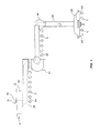
Figure 4 illustrates a bottom view of alight assembly 90, according to an embodiment of the present disclosure. Thelight assembly 90 is an example of theequipment 20 secured to theboom assembly 10 shown inFigures 1-3 . Thelight assembly 90 may include amain housing 92 having concentric, annular light-emittingdevices 94, which are spaced apart from one another by concentric,annular air passages 96 that may be in communication with the air delivery member 62 (shown inFigures 1-3 ). As such, airflow may be directed through thelight assembly 90 by way of theair passages 96. - As shown in
Figure 4 , theair passages 96 may be concentric, annular or circular passages. However, theair passages 96 may be various other shapes and sizes. Additionally, theair passages 96 may not be concentric, but may be positioned at various locations of thelight assembly 90. Additionally, thehousing 92 may be various shapes and sizes other than circular. -
Figure 5 illustrates a bottom view of alight assembly 100, according to an embodiment of the present disclosure. Thelight assembly 100 is an example of theequipment 20 secured to theboom assembly 10 shown inFigures 1-3 . Thelight assembly 100 may include amain housing 102 having a light-emittingsurface 104. A plurality ofair passages 106 are formed through the light-emittingsurface 104 and may be in communication with the air delivery member 62 (shown inFigures 1-3 ). - Optionally, the air passages may take the place of the light-surface, and vice versa. The
air passages 106 may be various shapes and sizes, other than circular. Additionally, thehousing 102 may be various shapes and sizes other than circular. -
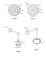
Figure 6 illustrates a lateral view of aboom assembly 110, according to an embodiment of the present disclosure. Theboom assembly 110 connects toequipment 112. Theequipment 112 may be a robotic operating assembly, a computer monitor, control panel, or the like. Air passages are formed through theequipment 112, as described above. -
Figure 7 illustrates a lateral view of aboom assembly 120, according to an embodiment of the present disclosure. Theboom assembly 120 connects toequipment 122. Theequipment 122 may be amonitor 122 having air passages formed therethrough, as described above. -
Figure 8 illustrates a lateral view ofequipment 200 secured to anequipment attachment arm 202 of aboom assembly 204, according to an embodiment of the present disclosure. Theequipment 200 may include a plurality of air-directingmembers 206 extending from abottom surface 208. The air-directingmembers 206 may be air nozzles, for example. Each air-directingmember 206 may be fluidly connected to arespective air passage 210 formed through thebottom surface 208. However, more or less air-directingmembers 206 than shown may be used. Additionally, theequipment 200 may include exposedair passages 210 that are not connected to air-directingmembers 206. - Each air-directing
member 206 may include a flow-control device 212, such as a valve. The flow-control device 212 allows the air-directingmember 206 to be selectively operated between open and closed positions. Thus, an operator may open certain air-directingmembers 206, close other air-directingmembers 206, and modulate air flow between open and closed positions with respect to other air-directingmembers 206. In this manner, airflow may be selectively directed through the air-directingmembers 206, independent of the movement of theboom assembly 204. - The flow-
control devices 212 of the air-directingmembers 206 may be manually operated. Optionally, theflow control devices 212 may be operatively connected to a control unit, such as a digital control unit. A user may control operation of theflow control devices 212 through the control unit, which may be formed with theequipment 200 and/or theboom assembly 204, or may be remotely located from therefrom. - The
flow control devices 212 may be used with any of the embodiments described above with respect toFigures 1-7 . -
Figure 9 illustrates a lateral view ofequipment 300 secured to anequipment attachment arm 302 of aboom assembly 304, according to an embodiment of the present disclosure. Theequipment 300 is similar to theequipment 200, except that anair manifold 306 may be secured to abottom surface 308 of theequipment 300. Theair manifold 306 is in fluid communication with one or more air passages (hidden from view) of theequipment 300. Theair manifold 306 includesair outlets 310. Air-directingmembers 312, such as the air-directingmembers 206 described with respect toFigure 8 , may be connected to theair outlets 310. Theair manifold 306 and the air-directingmembers 312 may be used with any of the embodiments described above with respect toFigures 1-7 . -
Figure 10 illustrates a lateral view ofequipment 400 secured to anequipment attachment arm 402 of aboom assembly 404, according to an embodiment of the present disclosure. Theequipment 400 may include an air-directingmember 406 secured to abottom surface 408. The air-directingmember 406 may be a louver or damper having a one or more flow-directingfins 410 that are pivotally secured to ahousing 412. Each flow-directingfin 410 is positioned with respect to an air passage. As such, each flow-directingfin 410 may be selectively controlled to open or close a particular air passage. For example, the flow-directingfins 410 may be moved between open and closed positions, or modulated therebetween. Acontrol knob 414 may be operatively connected to the flow-directingfins 410. Thecontrol knob 414 allows an operator to manually control theflow directing fins 410. Alternatively, thecontrol knob 414 may be a digital control unit configured to control operation of theflow directing fins 410. - The
housing 412 may include more or lessflow directing fins 410 than shown. Additionally, thehousing 412 may include exposed air passages that are not connected to a flow directing fins. Theflow control device 406 may be used with any of the embodiments described above with respect toFigures 1-7 . -
Figure 11 illustrates a lateral view ofequipment 500 secured to anequipment attachment arm 502 of aboom assembly 504, according to an embodiment of the present disclosure. Theequipment 500 is similar to theequipment 400, except that theequipment 500 may include a multiple air-directing members 506, each of which may be operatively connected to an air passage formed through theequipment 500. Each air-directing member 506 may be a louver or damper having flow-directingfins 508. Each air-directingmember member 506a has flow-directingfins 508 that are configured to direct airflow toward a centrallongitudinal axis 512, while air-directingmember 506b has flow-directingfins 508 that are configured to direct airflow away from the centrallongitudinal axis 512. Air-directingmember 506c has flow-directingfins 508 that are closed, while air-directingmember 506d has flow-directingfins 508 that are oriented to direct airflow vertically downward. Each of the air-directingmembers 506a-506d may be controlled to vary the orientations of the flow-directingfins 508. Each air-directingmember 506a-506d may include a separate and distinct control, such as a control knob or control unit. Optionally, all the air-directingmembers 506a-506d may be operatively connected to a single control unit on theequipment 500, theboom assembly 504, or remotely located therefrom. The single control unit may be a digital control unit that allows an operator to independently control each of the air-directingmembers 506a-506d. - More or less air-directing members 506 than shown may be used. Further, the
equipment 500 may include exposed air passages not connected to an air-directing member. The air-directing members 506 may be used with any of the embodiments described above with respect toFigures 1-7 . - Referring to
Figures 1-11 , the equipment secured to a boom assembly may be various types of equipment, such as used in clean environments. The equipment may include light assemblies, robotic operating devices, control panels, monitors, surgical instruments and devices, imaging systems or devices, medical imaging systems or devices, or various other devices, structures, and the like that may be secured to a boom assembly. The boom assemblies described above may be modular systems in which rotatable arms, connection joints, and the like may be selectively added and/or removed. The boom assemblies may be configured to engage various types of equipment, so that particular equipment may be secured to the boom assembly, later removed, and other equipment attached to the boom assembly in place of the original equipment. - Additionally, the boom assembly may be configured to accommodate various other components, other than an air delivery system. For example, the boom assembly may be configured to securely channel, retain, or the like, electrical power and control wiring, medical gas piping, vacuum channels, low voltage data wiring for telemetry and data, as well as video feed for a monitor, and the like.
- Embodiments of the present disclosure provide a boom assembly that creates a localized airflow environment within a target location or site, such as an operating environment. Embodiments provide a boom assembly that is configured to direct airflow from equipment secured to a boom assembly, which creates substantially laminar airflow within the target location or site. Further, turbulence caused from airflow from separate and distinct air delivery devices moving into and around the equipment may be pushed away from the target location site by the airflow directed out of the equipment secured to the boom assembly.
- Thus, embodiments of the present disclosure provide a boom assembly, system, and method that is configured to deliver air directly to a target site through equipment attached to a distal end of a boom.
- While various spatial and directional terms, such as top, bottom, lower, mid, lateral, horizontal, vertical, front and the like may be used to describe embodiments of the present disclosure, it is understood that such terms are merely used with respect to the orientations shown in the drawings. The orientations may be inverted, rotated, or otherwise changed, such that an upper portion is a lower portion, and vice versa, horizontal becomes vertical, and the like.
- It is to be understood that the above description is intended to be illustrative, and not restrictive. For example, the above-described embodiments (and/or aspects thereof) may be used in combination with each other. In addition, many modifications may be made to adapt a particular situation or material to the teachings of the various embodiments of the disclosure without departing from their scope. While the dimensions and types of materials described herein are intended to define the parameters of the various embodiments of the disclosure, the embodiments are by no means limiting and are exemplary embodiments. Many other embodiments will be apparent to those of skill in the art upon reviewing the above description. The scope of the various embodiments of the disclosure should, therefore, be determined with reference to the appended claims, along with the full scope of equivalents to which such claims are entitled. In the appended claims, the terms "including" and "in which" are used as the plain-English equivalents of the respective terms "comprising" and "wherein." Moreover, the terms "first," "second," and "third," etc. are used merely as labels, and are not intended to impose numerical requirements on their objects. Further, the limitations of the following claims are not written in means-plus-function format and are not intended to be interpreted based on 35 U.S.C. § 112, sixth paragraph, unless and until such claim limitations expressly use the phrase "means for" followed by a statement of function void of further structure.
- As used herein, an element or step recited in the singular and proceeded with the word "a" or "an" should be understood as not excluding plural of said elements or steps, unless such exclusion is explicitly stated. Furthermore, references to "one embodiment" are not intended to be interpreted as excluding the existence of additional embodiments that also incorporate the recited features. Moreover, unless explicitly stated to the contrary, embodiments "comprising" or "having" an element or a plurality of elements having a particular property may include additional such elements not having that property.
- This written description uses examples to disclose the various embodiments of the disclosure, including the best mode, and also to enable any person skilled in the art to practice the various embodiments of the disclosure, including making and using any devices or systems and performing any incorporated methods. The patentable scope of the various embodiments of the disclosure is defined by the claims, and may include other examples that occur to those skilled in the art. Such other examples are intended to be within the scope of the claims if the examples have structural elements that do not differ from the literal language of the claims, or if the examples include equivalent structural elements with insubstantial differences from the literal languages of the claims.
Claims (15)
- A boom assembly configured to movably secure equipment to a ceiling or plenum extending from the ceiling, the boom assembly comprising:an arm sub-assembly configured to be secured to the ceiling; andan air delivery member extending through and/or on the arm sub-assembly, wherein the air delivery member comprises a first end configured to be in communication with an air delivery chamber within the ceiling or plenum, and a second end configured to be in communication with air passages formed through the equipment, and wherein airflow is configured to be directed from the air delivery chamber out through the air passages formed through the equipment towards a target location.
- The boom assembly of claim 1, wherein the arm sub-assembly comprises a plurality of rotatable arms configured to move the equipment through various directions.
- The boom assembly of claim 1, wherein the air delivery member is separate and distinct from the arm sub-assembly.
- The boom assembly of claim 1, wherein the air delivery member is integrally formed through the boom assembly.
- The boom assembly of claim 1, wherein the air delivery member is formed of a fluid-tight material defining an air delivery channel.
- The boom assembly of claim 1, wherein the air delivery member comprises multiple openings formed over a length of the air delivery member.
- The boom assembly of claim 1, wherein the arm-subassembly is further configured to securely retain one or more of electrical power and control wiring, medical gas piping, vacuum channels, or data wiring.
- The boom assembly of claim 1, further comprising at least one air-directing member configured to be in fluid communication with at least one of the air passages.
- The boom assembly of claim 8, wherein the at least one air-directing member comprises an air nozzle operatively connected to a valve.
- The boom assembly of claim 8, wherein the at least one air-directing member comprises at least one flow-directing fin configured to be selectively moved between open and closed positions.
- A system configured to provide airflow to a target location, the system comprising:equipment configured to be positioned proximate the target location, wherein air passages are formed through at least a portion of the equipment; anda boom assembly configured to movably secure the equipment to a ceiling or plenum extending from the ceiling, the boom assembly comprising:an arm sub-assembly configured to be secured to the ceiling; andan air delivery member extending through and/or on the arm sub-assembly, wherein the air delivery member comprises a first end configured to be in communication with an air delivery chamber within the ceiling or plenum, and a second end in communication with the air passages formed through at least a portion of the equipment, and wherein airflow is configured to be directed from the air delivery chamber out through the air passages towards the target location.
- The system of claim 11, wherein the arm sub-assembly comprises a plurality of rotatable arm configured to move the equipment through various directions.
- The system of claim 11, wherein the air delivery member comprises multiple openings formed over a length of the air delivery member.
- The system of claim 11, further comprising at least one air-directing member in fluid communication with at least one of the air passages.
- A method of providing airflow to a target location, the method comprising:passing airflow from a plenum into an air delivery member within and/or on an arm sub-assembly connected to equipment;channeling the airflow from the plenum to the air delivery member and into air passages formed through the equipment;directing the airflow out of the air passages formed through the equipment and toward a target location proximate the equipment.
Applications Claiming Priority (2)
| Application Number | Priority Date | Filing Date | Title |
|---|---|---|---|
| US201261663712P | 2012-06-25 | 2012-06-25 | |
| US13/682,339 US20130344795A1 (en) | 2012-06-25 | 2012-11-20 | System and method for delivering air through a boom assembly |
Publications (2)
| Publication Number | Publication Date |
|---|---|
| EP2679213A2 true EP2679213A2 (en) | 2014-01-01 |
| EP2679213A3 EP2679213A3 (en) | 2014-08-06 |
Family
ID=48607068
Family Applications (1)
| Application Number | Title | Priority Date | Filing Date |
|---|---|---|---|
| EP13170380.3A Withdrawn EP2679213A3 (en) | 2012-06-25 | 2013-06-04 | System and method for delivering air through a boom assembly |
Country Status (3)
| Country | Link |
|---|---|
| US (1) | US20130344795A1 (en) |
| EP (1) | EP2679213A3 (en) |
| CN (1) | CN103512170A (en) |
Cited By (7)
| Publication number | Priority date | Publication date | Assignee | Title |
|---|---|---|---|---|
| WO2016116389A1 (en) * | 2015-01-20 | 2016-07-28 | Koninklijke Philips N.V. | Medical imaging with integrated air guidance |
| WO2017004523A1 (en) * | 2015-07-01 | 2017-01-05 | Kevin Joseph Schreiber | Airflow-channeling surgical light system and method |
| US9895202B2 (en) | 2015-07-01 | 2018-02-20 | Sld Technology, Inc. | Airflow-channeling surgical light system and method |
| WO2018087162A1 (en) * | 2016-11-08 | 2018-05-17 | Optimus Licensing Ag | Integrated operating room lighting and patient warming system - design and components |
| IT201800007200A1 (en) * | 2018-07-13 | 2020-01-13 | FAN LAMP | |
| WO2020012451A1 (en) * | 2018-07-13 | 2020-01-16 | Musco Carmelo | Ventilating lamp |
| US10775037B2 (en) | 2015-07-01 | 2020-09-15 | Sld Technology, Inc. | Airflow-channeling surgical light system and method |
Families Citing this family (10)
| Publication number | Priority date | Publication date | Assignee | Title |
|---|---|---|---|---|
| FI126595B (en) * | 2013-01-30 | 2017-02-28 | Merivaara Oy | Operating room lighting arrangement |
| US9341387B2 (en) * | 2013-05-30 | 2016-05-17 | Nortek Air Solutions, Llc | Illuminating airflow panel assembly |
| US10405942B2 (en) | 2015-10-07 | 2019-09-10 | Sld Technology, Inc. | Airframe system and method of controlling airflow |
| US9903115B2 (en) * | 2015-10-07 | 2018-02-27 | Sld Technology, Inc. | Airframe system and method of controlling airflow |
| US11186989B2 (en) * | 2015-10-07 | 2021-11-30 | Sld Technology, Inc. | Equipment support system and method of supporting equipment |
| CN105411787A (en) * | 2015-12-24 | 2016-03-23 | 王刚 | Medical hoisting tower for operating room |
| US10215441B2 (en) * | 2016-04-15 | 2019-02-26 | Hongyi CAI | Integrated light and heat arrangement of low profile light-emitting diode fixture |
| WO2017195041A1 (en) * | 2016-05-12 | 2017-11-16 | Price Industries Limited | Laminar flow diffuser with integrated lighting |
| TWI741539B (en) * | 2019-05-02 | 2021-10-01 | 國立成功大學 | Surgical smoke removing device and method therefor |
| US20220370272A1 (en) * | 2021-05-18 | 2022-11-24 | Sld Technology, Inc. | Modular patient lift system |
Citations (4)
| Publication number | Priority date | Publication date | Assignee | Title |
|---|---|---|---|---|
| US20100051563A1 (en) | 2008-08-29 | 2010-03-04 | Kevin Schreiber | Modular data center |
| US20110014061A1 (en) | 2003-03-20 | 2011-01-20 | Huntair, Inc. | Fan array control system |
| US20110097986A1 (en) | 2009-10-22 | 2011-04-28 | Huntair, Inc. | Ceiling system with integrated equipment support structure |
| US20110255704A1 (en) | 2010-04-15 | 2011-10-20 | Huntair, Inc. | Methods and systems for active sound attenuation in an air handling unit |
Family Cites Families (24)
| Publication number | Priority date | Publication date | Assignee | Title |
|---|---|---|---|---|
| US2173325A (en) * | 1936-02-24 | 1939-09-19 | American Sterilizer Co | Surgical operating luminaire |
| US3107863A (en) * | 1960-10-31 | 1963-10-22 | Reginald Robbins | Air directing isolation apparatus |
| DE2153743C3 (en) * | 1971-10-28 | 1979-08-16 | Daimler-Benz Ag, 7000 Stuttgart | Air nozzle for a ventilation system |
| DE2212493A1 (en) * | 1972-03-15 | 1973-09-27 | Hoechst Ag | KIT FOR CREATING ILLUMINATED ZONES IN ULTRA-CLEAN ATMOSPHERES |
| US3923482A (en) * | 1972-04-12 | 1975-12-02 | James V Knab | Clean air directing apparatus |
| SE365841B (en) * | 1972-09-26 | 1974-04-01 | A Nilsson | |
| FR2307230A1 (en) * | 1975-04-09 | 1976-11-05 | Kessler & Luch Kg | TUBULAR AIR OUTLET INTENDED TO BE CONNECTED TO AN AIR SUPPLY LAYED IN THE FLOOR OF A CONDITIONING SYSTEM |
| FR2348632A7 (en) * | 1976-04-13 | 1977-11-10 | Delbag Luftfilter Gmbh | Air conditioning system for operating theatres - has air supply system above false ceiling to provide laminar air curtain horizontally over operating table |
| AU5779286A (en) * | 1985-04-26 | 1986-11-18 | MTD Medical Development and Technology Ltd. | Method and means for supplying clean air to an operating room |
| US4967320A (en) * | 1989-04-24 | 1990-10-30 | Distinctively Different, Inc. | Dental protective air barrier light apparatus and method |
| GB2244126B (en) * | 1990-05-15 | 1994-03-02 | Univ Bath | Localised clean air system |
| NO934439D0 (en) * | 1993-12-06 | 1993-12-06 | Aet Arbeidsmiljoe Og Energitek | Device at ceiling mounted ventilation system |
| DE10058721C2 (en) * | 2000-11-25 | 2002-11-28 | Draeger Medical Ag | Operating light on a ceiling arm system |
| CA2476529C (en) * | 2002-02-25 | 2007-05-22 | Steris Inc. | Ergonomic controls in a surgical lighting system |
| US6602128B1 (en) * | 2002-05-24 | 2003-08-05 | Charles W. Spengler | Clean air room with a blower including a HEPA filter and ducts |
| US7073765B2 (en) * | 2002-11-13 | 2006-07-11 | Hill-Rom Services, Inc. | Apparatus for carrying medical equipment |
| US20060073784A1 (en) * | 2004-09-25 | 2006-04-06 | Terrel Porter | Air displacement upon a medical patient |
| FR2878019B1 (en) * | 2004-11-17 | 2007-05-18 | Alm Sa | CENTRAL DISTRIBUTION POST, CORRESPONDING SUPPORT AND MANUFACTURING METHOD. |
| SE532219C2 (en) * | 2006-02-28 | 2009-11-17 | Airsonett Ab | Method and apparatus for providing a clean air zone at an operating area in the medical field and use of said device |
| WO2008002728A2 (en) * | 2006-06-28 | 2008-01-03 | Alcon, Inc. | Control display positioning system |
| SE532217C2 (en) * | 2007-05-03 | 2009-11-17 | Airsonett Ab | Ventilation device for an operating room |
| US20100074681A1 (en) * | 2008-09-24 | 2010-03-25 | Shahriar Jamalzadeh | Equipment transfer system latching mechanism |
| US20100120349A1 (en) * | 2008-10-31 | 2010-05-13 | Airsonett Ab | Surgical theater ventilating devices and methods |
| DE102010054823A1 (en) * | 2010-12-16 | 2012-06-21 | TÜV Rheinland Industrie Service GmbH | Method for checking operating room, involves measuring flow conditions in operating room under operating lamp, where measurement results are evaluated, where operating lamp is adjusted by changing flow conditions |
-
2012
- 2012-11-20 US US13/682,339 patent/US20130344795A1/en not_active Abandoned
-
2013
- 2013-06-04 EP EP13170380.3A patent/EP2679213A3/en not_active Withdrawn
- 2013-06-25 CN CN201310254574.7A patent/CN103512170A/en active Pending
Patent Citations (4)
| Publication number | Priority date | Publication date | Assignee | Title |
|---|---|---|---|---|
| US20110014061A1 (en) | 2003-03-20 | 2011-01-20 | Huntair, Inc. | Fan array control system |
| US20100051563A1 (en) | 2008-08-29 | 2010-03-04 | Kevin Schreiber | Modular data center |
| US20110097986A1 (en) | 2009-10-22 | 2011-04-28 | Huntair, Inc. | Ceiling system with integrated equipment support structure |
| US20110255704A1 (en) | 2010-04-15 | 2011-10-20 | Huntair, Inc. | Methods and systems for active sound attenuation in an air handling unit |
Cited By (15)
| Publication number | Priority date | Publication date | Assignee | Title |
|---|---|---|---|---|
| US10512438B2 (en) | 2015-01-20 | 2019-12-24 | Koninklijke Philips N.V. | Medical imaging with integrated air guidance |
| WO2016116389A1 (en) * | 2015-01-20 | 2016-07-28 | Koninklijke Philips N.V. | Medical imaging with integrated air guidance |
| US10842451B2 (en) | 2015-01-20 | 2020-11-24 | Koninklijke Philips N.V. | Medical imaging with integrated air guidance |
| US20180008219A1 (en) * | 2015-01-20 | 2018-01-11 | Koninklijke Philips N.V. | Medical imaging with integrated air guidance |
| US20200085391A1 (en) * | 2015-01-20 | 2020-03-19 | Koninklijke Philips N.V. | Medical imaging with integrated air guidance |
| US10775037B2 (en) | 2015-07-01 | 2020-09-15 | Sld Technology, Inc. | Airflow-channeling surgical light system and method |
| WO2017004523A1 (en) * | 2015-07-01 | 2017-01-05 | Kevin Joseph Schreiber | Airflow-channeling surgical light system and method |
| US9895202B2 (en) | 2015-07-01 | 2018-02-20 | Sld Technology, Inc. | Airflow-channeling surgical light system and method |
| AU2016288607B2 (en) * | 2015-07-01 | 2020-10-15 | Sld Technology, Inc. | Airflow-channeling surgical light system and method |
| US9671100B2 (en) | 2015-07-01 | 2017-06-06 | Kevin Joseph Schreiber | Airflow-channeling surgical light system and method |
| US11555604B2 (en) | 2015-07-01 | 2023-01-17 | Sld Technology, Inc. | Airflow-channeling surgical light system and method |
| WO2018087162A1 (en) * | 2016-11-08 | 2018-05-17 | Optimus Licensing Ag | Integrated operating room lighting and patient warming system - design and components |
| US11389361B2 (en) | 2016-11-08 | 2022-07-19 | Optimus Licensing Ag | Integrated operating room lighting and patient warming system—design and components |
| WO2020012451A1 (en) * | 2018-07-13 | 2020-01-16 | Musco Carmelo | Ventilating lamp |
| IT201800007200A1 (en) * | 2018-07-13 | 2020-01-13 | FAN LAMP |
Also Published As
| Publication number | Publication date |
|---|---|
| US20130344795A1 (en) | 2013-12-26 |
| EP2679213A3 (en) | 2014-08-06 |
| CN103512170A (en) | 2014-01-15 |
Similar Documents
| Publication | Publication Date | Title |
|---|---|---|
| EP2679213A2 (en) | System and method for delivering air through a boom assembly | |
| JP5911862B2 (en) | lamp | |
| CN102667023B (en) | Ceiling system with integrated equipment support structure | |
| US20190234645A1 (en) | Sterile airflow delivery system | |
| US9310096B2 (en) | Overhead support system having adjustable lighting elements | |
| US10842451B2 (en) | Medical imaging with integrated air guidance | |
| EP2022435A1 (en) | Medical servicing system | |
| US20090288555A1 (en) | Method and device for providing a zone of clean air at an operation area and use of said device | |
| US9341387B2 (en) | Illuminating airflow panel assembly | |
| US20220081901A1 (en) | Equipment support system and method of supporting equipment | |
| CA2895473C (en) | Air filter assembly | |
| US20190374302A1 (en) | Airframe system and method of controlling airflow | |
| US20140191100A1 (en) | Adjustable equipment mount assembly for an overhead support module | |
| JP6017118B2 (en) | Air conditioning system | |
| US10874572B2 (en) | Particle deflection pad and method of use | |
| JP2010027274A (en) | Illumination device | |
| CN220423959U (en) | Disposable operation aseptic protective sleeve | |
| JP6865947B2 (en) | Soundproof structure of the blower of the house and the blower of the house | |
| JP3587628B2 (en) | Floor panel | |
| JP3564602B2 (en) | Ceiling-mounted indoor unit | |
| RU2575703C2 (en) | Ceiling for laminar air flow generation in operation room |
Legal Events
| Date | Code | Title | Description |
|---|---|---|---|
| PUAI | Public reference made under article 153(3) epc to a published international application that has entered the european phase |
Free format text: ORIGINAL CODE: 0009012 |
|
| AK | Designated contracting states |
Kind code of ref document: A2 Designated state(s): AL AT BE BG CH CY CZ DE DK EE ES FI FR GB GR HR HU IE IS IT LI LT LU LV MC MK MT NL NO PL PT RO RS SE SI SK SM TR |
|
| AX | Request for extension of the european patent |
Extension state: BA ME |
|
| PUAL | Search report despatched |
Free format text: ORIGINAL CODE: 0009013 |
|
| AK | Designated contracting states |
Kind code of ref document: A3 Designated state(s): AL AT BE BG CH CY CZ DE DK EE ES FI FR GB GR HR HU IE IS IT LI LT LU LV MC MK MT NL NO PL PT RO RS SE SI SK SM TR |
|
| AX | Request for extension of the european patent |
Extension state: BA ME |
|
| RIC1 | Information provided on ipc code assigned before grant |
Ipc: A61G 13/10 20060101AFI20140701BHEP Ipc: F24F 3/16 20060101ALI20140701BHEP Ipc: A61G 12/00 20060101ALI20140701BHEP |
|
| STAA | Information on the status of an ep patent application or granted ep patent |
Free format text: STATUS: THE APPLICATION IS DEEMED TO BE WITHDRAWN |
|
| 18D | Application deemed to be withdrawn |
Effective date: 20150207 |