EP2677223A1 - Fitting for connecting pipes, in particular flexible pipes - Google Patents
Fitting for connecting pipes, in particular flexible pipes Download PDFInfo
- Publication number
- EP2677223A1 EP2677223A1 EP13171013.9A EP13171013A EP2677223A1 EP 2677223 A1 EP2677223 A1 EP 2677223A1 EP 13171013 A EP13171013 A EP 13171013A EP 2677223 A1 EP2677223 A1 EP 2677223A1
- Authority
- EP
- European Patent Office
- Prior art keywords
- sleeve
- tubular element
- annular
- pipe
- blocking
- Prior art date
- Legal status (The legal status is an assumption and is not a legal conclusion. Google has not performed a legal analysis and makes no representation as to the accuracy of the status listed.)
- Granted
Links
Images


Classifications
-
- F—MECHANICAL ENGINEERING; LIGHTING; HEATING; WEAPONS; BLASTING
- F16—ENGINEERING ELEMENTS AND UNITS; GENERAL MEASURES FOR PRODUCING AND MAINTAINING EFFECTIVE FUNCTIONING OF MACHINES OR INSTALLATIONS; THERMAL INSULATION IN GENERAL
- F16L—PIPES; JOINTS OR FITTINGS FOR PIPES; SUPPORTS FOR PIPES, CABLES OR PROTECTIVE TUBING; MEANS FOR THERMAL INSULATION IN GENERAL
- F16L33/00—Arrangements for connecting hoses to rigid members; Rigid hose connectors, i.e. single members engaging both hoses
- F16L33/20—Undivided rings, sleeves or like members contracted on the hose or expanded in the hose by means of tools; Arrangements using such members
- F16L33/207—Undivided rings, sleeves or like members contracted on the hose or expanded in the hose by means of tools; Arrangements using such members only a sleeve being contracted on the hose
- F16L33/2071—Undivided rings, sleeves or like members contracted on the hose or expanded in the hose by means of tools; Arrangements using such members only a sleeve being contracted on the hose the sleeve being a separate connecting member
- F16L33/2078—Undivided rings, sleeves or like members contracted on the hose or expanded in the hose by means of tools; Arrangements using such members only a sleeve being contracted on the hose the sleeve being a separate connecting member connected to the rigid member via an intermediate element
-
- B—PERFORMING OPERATIONS; TRANSPORTING
- B25—HAND TOOLS; PORTABLE POWER-DRIVEN TOOLS; MANIPULATORS
- B25B—TOOLS OR BENCH DEVICES NOT OTHERWISE PROVIDED FOR, FOR FASTENING, CONNECTING, DISENGAGING OR HOLDING
- B25B27/00—Hand tools, specially adapted for fitting together or separating parts or objects whether or not involving some deformation, not otherwise provided for
- B25B27/02—Hand tools, specially adapted for fitting together or separating parts or objects whether or not involving some deformation, not otherwise provided for for connecting objects by press fit or detaching same
- B25B27/10—Hand tools, specially adapted for fitting together or separating parts or objects whether or not involving some deformation, not otherwise provided for for connecting objects by press fit or detaching same inserting fittings into hoses
Definitions
- the present invention relates to a fitting for connecting pipes, and is particularly applicable in the field of the connecting of flexible pipes for pressurised fluid circulation, for example water.
- the fitting of flexible pipes is generally realised by predisposing a fitting having an element of a rigid tubular shape, provided with two or more terminations couplable to a same number of pipes and able to place the pipes in reciprocal fluid communication with a fluid seal towards the outside environment.
- One or more terminations of the fitting destined for coupling with a flexible pipe, generally exhibits a profiled anchoring surface on which the flexible pipe is forced to adhere, and on which the flexible pipe stably grips following an elastic or permanent deformation.
- the anchoring surface can be realized by a surface exhibiting annular grooves, to which the pipe is forced to couple by virtue of the elastic deformability thereof.
- the anchoring surfaces are usually realized externally of the termination, and the termination itself is then inserted into an end of the pipe, to which it stably associates.
- the terminations of the fittings can all be provided with a grooved anchoring surface, for connecting pipes by deformation, or can be made for example with a threaded surface, on which the pipe is forced to engage by screwing; alternatively, a valve can be connected to the threaded surface of the terminal.
- external shields are usually employed (typically known as sleeves), for example metallic, which surround the end of the pipe coupled to the tubular element and are thus permanently deformed, for example by impressing a crushing with pliers, such as to generate a compression on the underlying pipe. In this way, the pipe is forced to crush against the underlying pipe, generating a stable coupling therewith.
- These connections are generally known as press-fits.
- seals are generally provided, to be interposed between each termination of the fitting and the respective piping to which it is coupled.
- these seals generally 0-rings, radially project beyond the volume of the grooves present on the anchoring surface and in this way they are able to provide a fluid seal even following the simple inserting of the pipe on the termination of the fitting; additionally, the seals can then be further deformed together with the pipe following the crushing of the external sleeve, if present, so as to adhere more effectively to both the termination of the fitting and to the pipe keyed thereto and prevent fluid leakage between the two towards the outside environment, even in high working pressure conditions.
- a first known solution includes the use of special seals affording localized radial irregularities, i.e. portions along the development circumference of the seal that are "lowered" with respect to the rest of the seal, which has a nominal and constant diameter.
- Each lowering in the seal realizes a passage between the two sides of the seal (with respect to the central axis of the seal which corresponds to the fluid flow direction); in this way the non-blocking of the sleeve corresponds to a poor crushing of the seal and thus to a leakage of fluid through the passages. If, on the contrary, the sleeve is correctly blocked, the seal is pressed radially to close the passages and no leakage ensues.
- the aim underpinning the present invention in its various aspects and/or embodiments, is to provide a fitting for connection of pipes that can obviate one or more of the mentioned drawbacks.
- a further aim of the present invention is to provide a fitting for connecting pipes that can autonomously evidence, during testing or in any case on first pressurizing, a missed blocking of the fitting on one or more pipes associated thereto.
- a further aim of the present invention is to provide a fitting for connecting connection of pipes characterised by a low cost of realisation.
- a further aim of the present invention is to provide a fitting for connecting pipes that is simple and rapid to realize.
- the invention relates to a fitting for connecting pipes, in particular including at least a flexible pipe, comprising:
- the fitting further comprises at least first blocking means comprising:
- the passage of the first blocking means from the insertion configuration to the blocking configuration occurs by means of a radial deformation of the sleeve, nearingly to the first tubular element, such as to compress the pipe between the sleeve and the first tubular element internally of the annular housing, the deformation being realised by acting on the external surface of the sleeve with a clamping profile of a blocking pliers, able to plastically deform the sleeve.
- first tubular element and the sleeve have a hollow cylindrical conformation and have a same longitudinal development axis.
- said blocking ring is housed in said annular gully of the sleeve in such a way as to be substantially flush with the internal surface of the sleeve and/or such as to realise an internal surface of the sleeve that is substantially cylindrical and/or has a constant diameter along the whole development of the sleeve along the longitudinal development axis.
- annular protrusion and said annular gully are realised substantially in a same position of the sleeve along the longitudinal development axis.
- the first tubular element comprises at least a first sealing element, externally enveloping the tubular element in such a way as to be interposed between the tubular element and a pipe inserted in said annular housing, said first sealing element being deformable, when the first blocking means are in blocking configuration, such as to inhibit a fluid communication between the first conduit and an external surface of the first tubular element.
- said annular protrusion and said annular gully are realised in a position of the sleeve, along said longitudinal axis development, that is close to, or at, the position occupied by the first sealing element on the tubular element, or the annular protrusion and the annular gully are substantially aligned along a plane that is perpendicular to the longitudinal development axis.
- the blocking ring is a closed ring, having a toroidal conformation, or - alternatively - it is a ring provided with a cut parallel to a central axis of the ring.
- the first tubular element comprises a plurality of ribs, extending externally of the tubular element and having a substantially annular profile, the ribs defining a plurality of grips for the pipe when the first blocking means are in the blocking configuration.
- the ribs extend radially from the external surface of the first tubular element over a rib diameter that is greater than an external diameter of the first tubular element.
- the first sealing element is enveloped externally of the first tubular element, between two adjacent ribs of the plurality of ribs, such as to be comprised radially within the rib diameter or such as to be substantially flush with the development of the ribs.
- the first tubular element comprises a second seal element, substantially identical to the first seal element, wound externally of the first tubular element in a different position along the longitudinal development axis.
- first and/or second seal element is toroidal, preferably being an 0-ring.
- the annular protrusion and the annular gully of the sleeve are realised in a position of the sleeve, along the longitudinal development axis, intermediate with respect to the positions occupied by the first and the second seal element on the first tubular element, in such a way that when the first blocking means are in the blocking configuration, the thrust of the locking ring on the underlying piping portion determines a deformation of the first and the second seal element and sealed blocking of the pipe on the first tubular element.
- the fitting comprises second blocking means comprising:
- the second tubular element comprises connecting means to a fluid source, for example a conduit, a tap or a tank.
- a fluid source for example a conduit, a tap or a tank.
- the connecting means comprise a threaded portion destined to connect to a corresponding counter-thread of the fluid source such as to set the second tubular element in fluid communication with the fluid source.
- the fitting comprises a plurality of tubular elements in reciprocal fluid communication, a respective piping being keyable onto each of the tubular elements, each tubular element preferably being identical to the first or second tubular element.
- the fitting has a linear conformation and the first tubular element has a longitudinal development coinciding with the longitudinal development axis of the second tubular element.
- the fitting has an angular conformation, i.e. the respective longitudinal development axes of the first and the second tubular elements form between them an angle that is not 180°, for example 45° or 90°.
- the fitting has a T shape and comprises three tubular elements of which two external tubular elements, aligned to one another, and a third intermediate tubular element interposed between the two external tubular elements and perpendicular thereto.
- the sleeve is configured to be blocked by pliers having a pinching profile of type B or type F or type H or type TH or type U.
- the present invention relates to a plant comprising at least a fitting according to one or more of the aspects and/or the claims and at least a pipe connected to the at least a fitting.
- the present invention relates to a production method of a fitting for connecting pipes, in particular flexible pipes, the method comprising steps of:
- the steps of realising, on an external surface of the sleeve, at least an annular protrusion and realising, on an internal surface of the sleeve, at least an annular gully are performed contemporaneously by means of a single operation of plastic deformation of the sleeve.
- the plastic deformation of the sleeve are preferably obtained by means of a moulding and/or forming and/or mechanical working operation.
- annular protrusion and the annular gully are realised in a single action, i.e. the creation of the annular gully on the internal surface of the sleeve determines the creation of the annular protrusion on the external surface of the sleeve.
- the step of predisposing a blocking ring comprises at least a step of realising a closed blocking ring, having a toroidal conformation, and optionally an additional step of cutting the ring such as to interrupt the circumferential continuity of the ring.
- the additional step of cutting the ring includes make a cut parallel to a central axis of the ring.
- the step of housing the blocking ring in the annular gully of the sleeve occurs before or after the step of mounting the sleeve to the first tubular element.
- the method comprises, preferably prior to the step of mounting the sleeve on the tubular element, a step of predisposing at least a sealing element, preferably two sealing elements, and enveloping it externally of the first tubular element in such a way that the sealing element is interposed between the first tubular element and a pipe inserted in the annular housing, the sealing element being preferably a seal or an O-ring.
- the steps of realising, on an external surface of the sleeve, at least an annular protrusion, and realising on an internal surface of the sleeve at least an annular gully are carried out on a same portion of the sleeve, along the longitudinal axis of development, and/or such that the annular protrusion and the annular gully are at the position occupied by the at least a sealing element on the tubular element.
- the method comprises, previously to the step of mounting the sleeve to the first tubular element, a step of predisposing a sleeve-holder removably associated to a mounting portion of the first tubular element, the sleeve-holder being configured such as to receive the sleeve and mount it on the first tubular element such that the sleeve stably envelops the first tubular element and defines the annular housing.
- the method comprises the step of inserting, in the annular housing, an end of a pipe to be connected to the fitting, such that the pipe is splined on the first tubular element and partially envelops the sleeve.
- the method comprises a step of exerting on the external surface of the sleeve, preferably by means of a clamping profile of a blocking pliers, a blocking force able to radially define, preferably plastically, the sleeve nearingly to the first tubular element, such as to compress the pipe between the sleeve and the first tubular element internally of the annular housing and stably and fluid-sealingly block the pipe in the annular housing.
- the at least a seal element deforms such as to inhibit a fluid communication between the first conduit and the external surface of the first tubular element.
- the method comprises steps of:
- the method comprises a step of predisposing, on the first and/or second tubular element, connecting means to a fluid source, for example a conduit, a tap or a tank, the connecting means comprising a threaded portion destined to connect to a corresponding counter-thread of the fluid source such as to set the tubular element in fluid communication with the fluid source.
- a fluid source for example a conduit, a tap or a tank
- the connecting means comprising a threaded portion destined to connect to a corresponding counter-thread of the fluid source such as to set the tubular element in fluid communication with the fluid source.
- the described fitting effectively carries out the function for which it was developed, i.e. signaling (with a fluid loss) a missed blocking of the connection on the pipe and realizing an excellent fluid seat when blocked.
- the described fitting, and the relative manufacturing method obviate the drawbacks described for the known solutions, in particular the solution with special seals and the solution described in patent EP 1 653 142 .
- the invention does not require the use of special seals (not always reliable) and is not limited to determined dimensions of the fitting, and on the other hand it does not require the use of a structurally complex sleeve.
- the described fitting is realizable at a modest cost, with respect to known fittings, for example thanks to the possibility of realizing the annular protrusion and the annular gully by means of a single deformation operation and adding the blocking ring, which has a unit cost (lined to the material of which it is made and the working operations for realizing it) that is extremely modest and substantially non-influential on the total cost of the fitting.
- the fitting of the present invention is usable with a plurality of blocking pliers, as will clearly emerge from the following part of the description.
- This flexibility is crucial for the object of the present invention, as a vital element regarding each pipe fitting is the fact that it has to be used with a conventional-type pliers that does not require a new-profile type of blocking clamp in order to be pinched.
- blocking pliers are devices responding to determined manufacturing standards (a very limited number of types exists).
- the pliers are expensive and widely used in the hydraulic sector; in substance, each operator possesses at least one and uses it with a multiplicity of fittings and installations.
- Each fitting has to guarantee compatibility with at least one of the pliers: if the fitting of the present invention required a new set of pliers, it would be difficult to place it on the market for fittings. For this reason the present fitting has been developed taking into account the defined standards for some blocking pliers, to which it responds.
- the fitting 1 is used for reciprocally connecting pipes T used for transporting pressurised fluid.
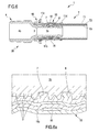
- the pipes T can be of the type made of a single material (for example rubber or plastic), as shown in figures 1 , 3 and 4 , or of the "multilayer" type.
- Multilayer pipes T are, for example, pips containing superposed layers of different materials in which, in the specific case, one or more of the layers is made of a metal material.
- the multilayer comprises three superposed layers T1, T2 and T3 (preferably glued to one another by means of intermediate adhesive layers); the external layers T1 and T3 are preferably made of plastic and the intermediate layer (T2 is made of metal material (for example aluminium).
- the fitting 1 comprises a first tubular element (or terminal) 3 and a second tubular element 4 respective provided with a first3a and a second inlet/outlet opening 4a and defining, internally thereof, respectively a first 3b and a second conduit 4b.
- the two tubular elements are connected to one another at respective opposite ends to the respective inlet/outlet opening, such that the first 3b and the second conduit 4b are in communication with one another and overall define an assembly conduit 2, which puts the first 3a and the second opening 4a in fluid communication with one another.
- the fitting 1 is further provided at least with first blocking means 10 comprising a sleeve 11 and a blocking ring 15.
- the sleeve 11 is associable, preferably removably, to the first tubular element 3 in such a way as to surround it externally and create, between the sleeve 11 and the first tubular element, an annular housing 12 destined to insertingly receive a pipe T; once the insertion has taken place the pipe is interposed between the first tubular element and the sleeve.
- the sleeve has an internal surface 11a, facing towards the first tubular element 3, and an external surface 11b; it is further provided with at least an annular protrusion 13, which extends from the external surface, and at least an annular gully 14 fashioned in the internal surface at the annular protrusion 13.
- the blocking ring 15 is housable in the annular gully 14.
- the first blocking means 10 are configured to operate in an inserting configuration, in which they enable insertion of the pipe T in the annular housing 12, and in a blocked configuration, in which they stably and fluid-sealingly block the pipe in the annular housing.
- the passage of the first blocking means 10 from the insertion configuration to the blocking configuration occurs by means of a radial deformation of the sleeve 11, nearingly to the first tubular element 3, such as to compress the pipe T between the sleeve and the first tubular element internally of the annular housing.
- This deformation is realized by acting on the external surface 11b of the sleeve with a clamping profile P1 of a clamping pliers P (visible in figures 4 and 5 ), able to plastically deform the sleeve.
- the passage of the blocking means into the blocking configuration determines a reduction of the radial extension of the annular housing 12, caused by the nearing of the sleeve 11 to the first tubular element 3, and a consequent compression of the pipe T internally of the annular housing.
- the blocking means 10 are illustrated with reference to the first tubular element (or terminal) 3.
- the blocking means may of course be replicated for the second tubular element (or terminal) 4 (for blocking the respective pipe) and possible for further tubular elements of the fitting.
- the first tubular element 3 and the sleeve 11 preferably have a hollow cylindrical conformation and exhibit a same longitudinal development axis X.
- the blocking ring 15 is housed in the annular gully 14 of the sleeve 11 in such a way as to be substantially flush with the internal surface 11a of the sleeve, i.e. to realize an internal surface 11 of the sleeve that is substantially cylindrical.
- the diameter of the internal surface of the sleeve (housing the ring 15) is constant along the whole development of the sleeve along the longitudinal development axis X.
- the annular protrusion 13 and the annular gully 14 are made in a same position of the sleeve 11 along the longitudinal development axis X.
- the correspondence between the protrusion and the gully is linked both to the correct functioning of the blocking means (as it is the protrusion which presses on the underlying ring, the ring having to be aligned therewith) and to the manufacturing process of the sleeve (which advantageously occurs by means of a single deformation which creates the annular protrusion and gully).
- the annular protrusion 13 and the annular gully 14 are substantially complementary, one being the "negative" of the other; the thickness (or external volume) of the protrusion, calculated as the distance from the external surface 11b of the sleeve, substantially corresponds to the depth of the gully 14; in other words, the addition of material on the external surface of the sleeve corresponds to the lack of material on the internal surface.
- the first tubular element 3 comprises at least a first seal element 7, externally enveloped on the tubular element such as to be interposed between it and a pipe T inserted in the annular housing 12.
- the first seal element 7 is able to deform, when the first blocking means 10 are in the blocked configuration, in order to inhibit a fluid communication between the first conduit 3b and an external surface of the first tubular element 3.
- the seal element 7 is elastic; in particular, it is a seal having an appropriately shaped section.
- the annular protrusion 13 and the annular gully 14 are preferably realised in a position of the sleeve 11, along the longitudinal development axis X, at the position occupied by the first seal element on the tubular element; in other words, the annular protrusion and the annular gully are aligned along a perpendicular plane to the longitudinal development axis X.
- the sleeve 11 preferably has a thickness, calculated as the distance between the internal surface 11a and the external surface 11b, that is substantially uniform over the whole longitudinal development thereof.
- the deforming thrust of the sleeve 11 preferably determines a radial nearing to the first tubular element 3 by the annular protrusion 13 and the blocking ring 15, housed in the annular gully 14; this thrust transmits through the blocking ring 15 to the underlying portion of pipe T at the first seal element 7, determining a deformation of the first seal element 7 and a sealed blocking of the pipe on the first tubular element.
- the blocking ring 15 can be a closed ring, with a toroidal conformation, or, alternatively, a ring provided with a cut.
- the cut of the ring is parallel to a central axis of the ring.
- the blocking ring is preferably made of rubber or a plastic material.
- the blocking ring 15 preferably has an external diameter that substantially corresponds to the diameter of the bottom of the annular ring 14, such that when it is inserted therein it is maintained stably internally of the gully by effect of the snug interference with the lateral walls of the gully.
- the ring 15 has a diameter that is such as to precisely occupy the annular gully 14 without accidentally exiting therefrom.
- the blocking ring is deformed such as to be insertable internally of the sleeve, and when it reaches the annular gully it is free to return to the initial shape thereof and thus occupy the annular gully. Additionally, or alternatively, the blocking ring is maintained in the annular gully by gluing.
- the blocking ring When the blocking ring comprises a cut making it discontinuous along the circumferential development thereof, it preferably has an elasticity that is such as to determine, when it is flexed by nearing or distancing the ends at the cut position, the development of an elastic force tending to return it into a rest configuration.
- This elasticity enables easy mounting of the ring: in fact it is deformed during the insertion in the sleeve and, on reaching the annular gully, the elasticity reopens it so that it occupies the gully; this elasticity further maintains it stably in contact with the bottom surface of the annular gully without any need to perform other operations.
- the blocking ring preferably has a radial thickness (calculated as the difference between the external diameter thereof and the internal diameter thereof) comprised between 0.3mm and 3mm or comprised between 0.8mm and 1.6mm, preferably about 1.2mm.
- the first tubular element 3 comprises a plurality of ribs 9 extending externally of the tubular element and having a substantially annular profile; the ribs define a plurality of grips for the pipe when the first blocking means are in the blocking configuration.
- the ribs 9 extend radially from the external surface of the first tubular element over a rib diameter that is greater than an external diameter of the first tubular element 3.
- the first sealing element 7 is enveloped externally of the first tubular element, between two adjacent ribs, such as to be comprised radially within the rib diameter or such as to be substantially flush with the development of the ribs 9.
- the first sealing element 7 is positioned between two adjacent ribs 9 so as not to interfere with a pipe T inserted in the annular housing 12 and such that (as previously illustrated) it does not realise a fluid seal between the first tubular element 3 and the pipe T when the first gripping means 10 are in the insertion configuration (with the aim of being able to detect a missed blocking of the fitting).
- the first blocking means when the first blocking means are in the blocked configuration, the combined action of the plurality of ribs 9 and the radial compression of the sleeve 11 towards the first tubular element 3 prevents de-insertion of the pipe T from the annular housing 12.
- the compression of the pipe T on the plurality of ribs 9 advantageously determines a deformation of the pipe by action of the plurality of fibs (clearly visible in figures 5 , 6 and 6a ) with a consequent jointing of the pipe on the ribs.
- the blocking ring 15 preferably has a width, measured parallel to the longitudinal development axis X, comprised between 2mm and 4mm or comprised between 2.5mm and 3.5mm or comprised between 2.8mm and 3.2mm, preferably about 3mm.
- the annular gully 14 preferably has a respective width, measured parallel to the longitudinal development axis X, comprised between 2mm and 6mm or comprised between 3mm and 5mm, preferably about 4mm.
- the annular gully might not be completely filled between the two lateral walls thereof by the blocking ring, but instead can maintain, on one or both sides of the blocking ring, a free space (see figures 1 , 3 , 8 , 9, 10 ).
- This space can be filled by the blocking ring when, by effect of the passage of the blocking means into the blocked configuration (i.e.
- the first tubular element 3 preferably comprises a second sealing element 8, substantially identical to the first sealing element 7, wound externally of the first tubular element in a different position along the longitudinal development axis X.
- the first and the second seal element preferably have a toroidal shape, and are both preferably 0-rings, widely known and used in the sector.
- the annular protrusion 13 and the annular gully 14 of the sleeve are preferably realised in a position of the sleeve 11 along the longitudinal development axis X, intermediate with respect to the positions occupied by the first and the second sealing element on the tubular element, such that when the first blocking means are in the blocked configuration, the thrust of the blocking ring 15 on the underlying portion of pipe T determines a deformation of the first 7 and the second sealing element 8 and a sealed blocking of the pipe on the first tubular element.
- the annular gully and the blocking ring cannot extend indefinitely in width, between the longitudinal ends of the sleeve, although preferably they are maintained within a width limit fixable at about 10mm.
- the annular gully occupies a substantially median position along the development of the sleeve with respect to the longitudinal axis X.
- the annular gully is preferably straddling one or both the sealing elements, as shown by way of example in figures 1 , 3 , 8 and 9 .
- the annular gully 14 interests the overlying zone comprised between the two sealing elements 7 and 8, extending limitedly externally of the elements.
- the pressure exerted during the blocking by the blocking ring is indicated (and especially designed) to interact with the sealing elements (by pressing and deforming them) and the portions adjacent thereto, but it is not recommended for compressing portions of pipes exclusively overlying one or more ribs.
- the pressure on parts that are distant from the sealing elements can cause excessive stress on the pipe, which can burst or be cut by effect of the shear counter-thrust exerted by the ribs.
- a further positioning constraint (preferably median) of the annular gully is due to the fact that the fitting has to be blockable using conventional pliers; it is necessary to avoid both the protrusion from being involved by the clamping profile P1 (in which case the sealing ring would be pushed insufficiently in a radial sense) and the protrusion from being excessively pressed by the profile P1 (in which case the pipe might excessively deform and break).
- the first tubular element 3 preferably exhibits, at the opposite end to the first inlet/outlet opening 3a, an abutting element 3c which extends distancingly from the external surface of the first tubular element and is able to define an abutting surface for a pipe T splined on the tubular element.
- the abutting element has a radial dimension that is greater than the external surface of the first tubular element, measured distancingly from the longitudinal development axis X.
- the first tubular element 3 preferably comprises an assembly portion 3d and the first blocking means 10 comprise a sleeve-bearing element 16 (preferably distinct from the sleeve (11) removably associable to the assembly portion; this sleeve-bearing element is configured to assembly the sleeve 11 to the first tubular element 3 in such a way that the sleeve stably surrounds the first tubular element and defines the annular housing 12.
- the sleeve-bearing element 16 preferably has an annular conformation and, when associated to the assembly portion, exhibits a central axis coinciding with the longitudinal development axis X.
- the sleeve-bearing element preferably extends along the central axis between a first annular engaging end 16a to the assembly portion of the first tubular element and a second annular engaging end 16b able to receive the sleeve.
- the assembly portion 3d of the first tubular element is preferably positioned at the abutting element 3c and consists of an annular gully (see figures 2 and 8 ).
- the assembly of the sleeve (associated to the sleeve-bearing element) to the tubular element3 preferably occurs with a press-fit by insertion of the first annular engaging end 16a into the gully defining the assembly portion 3d.
- the sleeve extends, along the longitudinal development axis X, between a first end 11c, destined to be mounted to the first tubular element 3, and a second end 11 d, opposite the first end, free and defining an opening for insertion of the pipe T in the annular housing.
- the first end of the sleeve is preferably associable to the sleeve-bearing element 16, in particular the second annular engaging end 16b.
- the second end 11d preferably comprises a lead-in (for example a flaring towards the outside) to facilitate the insertion of the end of the pipe to be connected.
- the sleeve-bearing element preferably comprises one or more openings 16c fashioned in one or more circumferential positions of the sleeve-bearing element and passing between the outside and inside of the sleeve-bearing element; these openings (overall defining a window-type hatch about the sleeve-bearing element) enable the observation (from outside the sleeve) of the pipe T inserted in the housing 12 with the aim of verifying the correct positioning of the pipe before proceeding to the blocking thereof in the fitting.
- the fitting 1 can comprise second blocking means, for example identical to the first blocking means 10 and destined to cooperate with a second tubular element in order to block a further pipe T.
- the second blocking means comprise a respective sleeve (with annular protrusion and gully) and a respective blocking ring.
- the second tubular element 4 of the fitting 1 comprises (in the place of second blocking means) connecting means 20 to a fluid source, for example a conduit, a tap or a tank (not shown and of known type).
- the connecting means preferably comprise a threaded portion destined to connect to a corresponding counter-thread of the fluid source such as to set the second tubular element 4 in fluid communication with the fluid source.
- the connecting means 20 preferably comprise a manoeuvring portion M engageable by a screwing tool.
- the manoeuvring portion M is generally a hexagonal projection, having a radial dimension that is greater than a the tubular element and able to be manoeuvred with a wrench to realize a sufficiently tight fastening of the device to the fluid source.
- the manoeuvring portion M is preferably realized on the abutting element 3c, such as to define a grip of the fitting 1 and at the same time be engaged to a screwing tool 1.
- the fitting preferably comprises a plurality of tubular elements in fluid communication with one another, a respective pipe being splinable on each of the tubular element, each tubular element being preferably identical to the first or second tubular element.
- the first 3 and/or the second tubular element 4 are preferably made of metal, preferably brass (for example yellow brass CW602N) or steel, or of plastic material (for example technopolymer PPSU).
- the sleeve 11 is made of a metal material, preferably steel (for example stainless steel AISI 304).
- the blocking ring 15 is preferably made of plastic or rubber or metal.
- the sealing elements 7 and 8 are preferably made of rubber (for example synthetic rubber EPDM - Ethylene-Propylene Diene Monomer ) .
- the pipe T is preferably made of plastic or, alternatively it is a multilayer pipe comprising an external layer T1 made of plastic, an intermediate layer T2 made of metal and an internal layer T3 made of plastic.
- the fitting of the present invention conforms to standards for use with potable water.
- the maximum working temperature can be 120°C in continuous functioning and the maximum working pressure is 10 bar.
- the embodiment shown in the figures illustrates a fitting having a linear conformation, in which the first and the second tubular element have the respective longitudinal extension axes coinciding with one another.
- the fitting of the present invention can have an angular conformation, i.e. the respective longitudinal development axes of the first and the second tubular element form, with one another, an angle which is not 180°, for example 45° or 90°.
- the angle between the tubular elements does not influence the technical characteristics described, nor the functioning of the fitting, although it enables arranging the different fittings usable in a plant in accordance with the angle between the pipes to be connected.
- the fitting can also have a T conformation and comprise three tubular elements of which two external tubular elements aligned to one another and third intermediate tubular element interposed between the two external tubular elements and perpendicular thereto.
- the sleeve 11 of the present invention is configured to be blocked by means of pliers having a clamping profile of type B or type F or type H or type TH or type U, with reference to clamping standards of known type in the hydraulic sector.
- the sleeve is conformed such that with each of the pliers the deformation of the blocking means is of the correct entity, i.e. neither insufficient (in which case there would be seal problems) nor excessive (in which case the pipe might be damaged).
- the dimensions are for a fitting structured to house a pipe T having a determined diameter. It is obviously possible to realize fittings for pipes of each diameter, by appropriately proportioning the dimensions of the single components (for example proportioning the dimensions shown in the figures.
- Figure 10 in particular illustrates the first blocking means 10.
- the dimension denoted by letter A indicates the width of the seal ring
- the size denoted by letter B indicates the internal diameter of the sleeve
- the size denoted by letter C indicates the external diameter of the sleeve (calculated as the radial dimension of the protrusion 13).
- annular protrusions can be included (for example two or three) in distinct positions of the sleeve and corresponding annular gullies with blocking rings.
- the production method of a fitting according to the present invention comprises steps of:
- the step of realising the annular protrusion and realising the annular gully are advantageously carried out contemporaneously by means of a single plastic deforming operation of the sleeve.
- the step of predisposing the blocking ring preferably includes realizing a closed blocking ring having a toroidal conformation (typically in the case of a rubber blocking ring), or realizing a closed ring and thus cut the ring (preferably in the case of a plastic blocking ring).
- the first tubular element 3 is predisposed with the first sealing element 7 and possibly the second sealing element 8 located in the respective seatings between two adjacent ribs. Thereafter, the tubular element 3 is inserted internally of the terminal section of a pipe T, such that the ribs 9 can act on the pipe and retain it couplingly with the tubular element and the sleeve externally envelops the terminal section of the pipe.
- the pipe obviously undergoes a deformation, preferably permanent (in particular in the case of a multilayer pipe).
- the presence of the sleeve in the annular protrusion and the underlying blocking ring enables locally availing of a surplus of material for pressing the underlying sealing element; this increase in material is necessary for operating with seals which do not project from the ribs (and which thus enable detection of the missed blocking of the fitting); without the blocking ring the drawback of the prior art would result, as there would be a "gap" at the position of the protrusion on the internal side of the sleeve, which would prevent transfer of the thrust from the pipe to the underlying sealing element, with a consequent poor seal even with the fitting tightly fastened.
- the sleeve has been acted on by modifying the structure thereof, without any need for modifications to the clamping profile of the pliers.
- a "classic" sleeve can be taken (i.e. of known type, meaning smooth and uniformly cylindrical on both internal and external sides) and modified by plastically deforming it such as to create the annular gully (a space) internally thereof and the corresponding annular protrusion externally thereof; then the sealing ring is inserted into the gully with the function of a washer (or filling material).
- seals for example 0-rings
- seals of entirely conventional type, simply by selecting them with a diameter of less than the diameter of the ribs.
Abstract
Description
- The present invention relates to a fitting for connecting pipes, and is particularly applicable in the field of the connecting of flexible pipes for pressurised fluid circulation, for example water.
- As is known, the fitting of flexible pipes is generally realised by predisposing a fitting having an element of a rigid tubular shape, provided with two or more terminations couplable to a same number of pipes and able to place the pipes in reciprocal fluid communication with a fluid seal towards the outside environment.
- One or more terminations of the fitting, destined for coupling with a flexible pipe, generally exhibits a profiled anchoring surface on which the flexible pipe is forced to adhere, and on which the flexible pipe stably grips following an elastic or permanent deformation. The anchoring surface can be realized by a surface exhibiting annular grooves, to which the pipe is forced to couple by virtue of the elastic deformability thereof. The anchoring surfaces are usually realized externally of the termination, and the termination itself is then inserted into an end of the pipe, to which it stably associates. The terminations of the fittings can all be provided with a grooved anchoring surface, for connecting pipes by deformation, or can be made for example with a threaded surface, on which the pipe is forced to engage by screwing; alternatively, a valve can be connected to the threaded surface of the terminal. With the aim of guaranteeing a fluid seal between the inside of the tubular element and the outside of the pipe associated thereto, and thus preventing leakage of fluid towards the outside, external shields are usually employed (typically known as sleeves), for example metallic, which surround the end of the pipe coupled to the tubular element and are thus permanently deformed, for example by impressing a crushing with pliers, such as to generate a compression on the underlying pipe. In this way, the pipe is forced to crush against the underlying pipe, generating a stable coupling therewith. These connections are generally known as press-fits.
- With the aim of improving the fluid seal between the inside of the fitting/pipe connection and the external environment, seals are generally provided, to be interposed between each termination of the fitting and the respective piping to which it is coupled. In some types of known fittings, these seals, generally 0-rings, radially project beyond the volume of the grooves present on the anchoring surface and in this way they are able to provide a fluid seal even following the simple inserting of the pipe on the termination of the fitting; additionally, the seals can then be further deformed together with the pipe following the crushing of the external sleeve, if present, so as to adhere more effectively to both the termination of the fitting and to the pipe keyed thereto and prevent fluid leakage between the two towards the outside environment, even in high working pressure conditions.
- The type of fitting described above exhibits some drawbacks. In fact, especially in complex plants and with a high number of connections, it is often advantageous to perform all the fittings in a first step, and then after, with the connections fitted, to proceed to blocking the external sleeves by crushing, for example using dedicated pliers (well known to operators and technical experts in the sector). This setting-up mode can lead, due to the large number of fittings to be blocked, to accidentally omitting to block one or more of the sleeve-pipe couplings. This can also happed for domestic plants or in any case plants that are less complex, as they are attributable to accidental occurrences or simple forgetfulness. It has been noted that during the step of testing the plant, and in particular the pressuring thereof, also following a missed blocking of one or more sleeves on the pipe, the seals predisposed between the terminations of the connecting elements and the pipes coupled thereto generate in any case a sufficient seal to prevent leakage and thus localized loss of fluid, also at non-blocked couplings. This is due to the fact that the seals deform in any case, though slightly, following insertion of the pipes of the terminal, and thus sets the seal in the sealed condition, sufficient to prevent leakage. Unfortunately the fluid seal of the non-blocked seals can give rise to leakage over time, for example due to de-inserting of the pipes, which leaks are however not encountered during the testing step for the above-mentioned reasons.
- To obviate this drawback, use is known of a different type of fitting, in which the seals are wound about the terminal of the fitting in such a way as not to project beyond the radial volume defined by the grooves of the anchoring surface. In this way, following the predisposing of the pipe on the fitting termination, the seals do not interfere with the pipe and thus do not realize any fluid seat between the inside of the fitting and the outside of the pipe. Thus, during the plant testing step (for example with a testing pressure of greater than 1 bar), the fitting-pipe connection inevitably loses liquid, and this can be immediately observed in the form of a load loss on the plant; this is indicative of the fact that a fitting has not been correctly blocked on the respective pipe.
- In this context, it has been found that the mere use of small-diameter seals (i.e. smaller 0-rings, such as not to pass beyond the crests of the anchoring surfaces), though enabling the detecting of the missed pinching, determines however a poor seal of the fitting even after blocking; this is due to the reduction of the dimensions of the seal, which does not correctly interfere with the terminal and pipe, even when the sleeve is pressed.
- To obviate this drawback, the prior art has proposed two different solutions. A first known solution includes the use of special seals affording localized radial irregularities, i.e. portions along the development circumference of the seal that are "lowered" with respect to the rest of the seal, which has a nominal and constant diameter. Each lowering in the seal realizes a passage between the two sides of the seal (with respect to the central axis of the seal which corresponds to the fluid flow direction); in this way the non-blocking of the sleeve corresponds to a poor crushing of the seal and thus to a leakage of fluid through the passages. If, on the contrary, the sleeve is correctly blocked, the seal is pressed radially to close the passages and no leakage ensues. In substance, the special seals enable easy verification of the correct blocking of all the sleeves of the plant, but present further drawbacks. In fact, it is clear that this solution can be implemented only on sufficiently large seals (in terms of diameter and/or thickness), i.e. provided with a sufficient quantity of material, such as to enable realizing the lowered portions without weakening the seal (and making it susceptible to wear and breakage).
- Further, manufacturing the special seals as well as making them sufficiently available on the market and providing replacement seals can be complicated and expensive. In the case of small seals it is possible to reduce the internal diameter of the connecting conduit (freeing up space to be destined to the thickness of the seal), but this limits the fluid flow in the fitting. Further, the reduction of the internal diameter of the fitting can sometimes not respond to the specifications required for obtaining product certification.
- An alternative solution to the above is described in patent document
EP 1 653 142 . This solution includes use of a sleeve having an annular portion with an increased thickness in an external direction with respect to the rest of the sleeve (in which the thickness is constant); the internal surface of the sleeve is cylindrical and has a uniform diameter, like known-type fittings. The above-described annular portion enables having available, during the blocking step, of a quantity of additional material in the part of sleeve destined to press the underlying seal (not projecting beyond the anchoring grooves). This would enable obtaining a correct deformation of the seal and therefore an adequate fluid seal. The correct functioning of the solution of the patent is subordinated to the lack of "gaps" in the internal surface of the sleeve, in particular at the external annular portion of the sleeve. In fact, the additional material of the external portion works by transferring the pressure of the pliers to the underlying seal only if the internal surface of the sleeve is maintained in contact with the pipe interposed between the sleeve and the seal. - However the Applicant has found that the latter solution described above is not free of relevant drawbacks. In fact, the manufacturing of a sleeve of the type described in patent
EP 1 653 142 , due exactly to the conformation thereof, is technically complex and characterised by a high cost. - In this situation the aim underpinning the present invention, in its various aspects and/or embodiments, is to provide a fitting for connection of pipes that can obviate one or more of the mentioned drawbacks. A further aim of the present invention is to provide a fitting for connecting pipes that can autonomously evidence, during testing or in any case on first pressurizing, a missed blocking of the fitting on one or more pipes associated thereto.
- A further aim of the present invention is to provide a fitting for connecting connection of pipes characterised by a low cost of realisation.
- A further aim of the present invention is to provide a fitting for connecting pipes that is simple and rapid to realize.
- These aims, and others besides, which will more fully emerge during the following description, are substantially attained by a fitting for connecting pipes according to one or more of the accompany claims, each of which taken one by one (without the relative dependencies) or in any combination with the other claims, as well as according to the following aspects and/or embodiments, variously combined, also with the above-mentioned claims.
- In a first aspect, the invention relates to a fitting for connecting pipes, in particular including at least a flexible pipe, comprising:
- at least a first tubular element provided, at an end thereof, with a first inlet/outlet opening and defining internally thereof a first conduit;
- at least a second tubular element provided, at an end thereof, with a second inlet/outlet opening and defining internally thereof a second conduit,
- In an aspect, the fitting further comprises at least first blocking means comprising:
- a sleeve associable to the first tubular element such as to surround the first tubular element externally and to create, between the sleeve and the first tubular element, an annular housing destined to insertingly receive a pipe, the pipe being interposed between the first tubular element and the sleeve, said sleeve having an internal surface, facing towards the first tubular element, and an external surface, and being provided with at least an annular protrusion extending from said external surface and with at least an annular gully afforded in said internal surface at said annular protrusion;
- at least a blocking ring housable in said at least an annular gully of said sleeve; said first blocking means being configured for operating at least in an insertion configuration, in which they enable insertion of a pipe into said annular housing, and a blocked configuration, in which they stably and fluid-sealingly block the pipe in the annular housing.
- In an aspect the passage of the first blocking means from the insertion configuration to the blocking configuration occurs by means of a radial deformation of the sleeve, nearingly to the first tubular element, such as to compress the pipe between the sleeve and the first tubular element internally of the annular housing, the deformation being realised by acting on the external surface of the sleeve with a clamping profile of a blocking pliers, able to plastically deform the sleeve.
- In an aspect the first tubular element and the sleeve have a hollow cylindrical conformation and have a same longitudinal development axis. In an aspect said blocking ring is housed in said annular gully of the sleeve in such a way as to be substantially flush with the internal surface of the sleeve and/or such as to realise an internal surface of the sleeve that is substantially cylindrical and/or has a constant diameter along the whole development of the sleeve along the longitudinal development axis.
- In an aspect the annular protrusion and said annular gully are realised substantially in a same position of the sleeve along the longitudinal development axis.
- In an aspect the first tubular element comprises at least a first sealing element, externally enveloping the tubular element in such a way as to be interposed between the tubular element and a pipe inserted in said annular housing, said first sealing element being deformable, when the first blocking means are in blocking configuration, such as to inhibit a fluid communication between the first conduit and an external surface of the first tubular element.
- In an aspect, said annular protrusion and said annular gully are realised in a position of the sleeve, along said longitudinal axis development, that is close to, or at, the position occupied by the first sealing element on the tubular element, or the annular protrusion and the annular gully are substantially aligned along a plane that is perpendicular to the longitudinal development axis.
- In an aspect, the blocking ring is a closed ring, having a toroidal conformation, or - alternatively - it is a ring provided with a cut parallel to a central axis of the ring.
- In an aspect, the first tubular element comprises a plurality of ribs, extending externally of the tubular element and having a substantially annular profile, the ribs defining a plurality of grips for the pipe when the first blocking means are in the blocking configuration. In an aspect the ribs extend radially from the external surface of the first tubular element over a rib diameter that is greater than an external diameter of the first tubular element.
- In an aspect, the first sealing element is enveloped externally of the first tubular element, between two adjacent ribs of the plurality of ribs, such as to be comprised radially within the rib diameter or such as to be substantially flush with the development of the ribs.
- In an aspect, the first tubular element comprises a second seal element, substantially identical to the first seal element, wound externally of the first tubular element in a different position along the longitudinal development axis.
- In an aspect the first and/or second seal element is toroidal, preferably being an 0-ring.
- In an aspect, the annular protrusion and the annular gully of the sleeve are realised in a position of the sleeve, along the longitudinal development axis, intermediate with respect to the positions occupied by the first and the second seal element on the first tubular element, in such a way that when the first blocking means are in the blocking configuration, the thrust of the locking ring on the underlying piping portion determines a deformation of the first and the second seal element and sealed blocking of the pipe on the first tubular element.
- In an aspect the fitting comprises second blocking means comprising:
- a respective sleeve associated to the second tubular element in such a way as to surround it externally and to create, between the sleeve and the second tubular element, a respective annular housing destined to insertingly receive a pipe, the pipe being interposed between the second tubular element and the sleeve, said respective sleeve having an internal surface, facing towards the second tubular element, and an external surface, and being provided with at least an annular protrusion extending from the external surface and at least an annular gully fashioned in the internal surface at the annular protrusion;
- a respective blocking ring housable in the at least an annular gully of the sleeve;
- In an alternative aspect, the second tubular element comprises connecting means to a fluid source, for example a conduit, a tap or a tank.
- In an aspect, the connecting means comprise a threaded portion destined to connect to a corresponding counter-thread of the fluid source such as to set the second tubular element in fluid communication with the fluid source.
- In an aspect, according to a possible embodiment of the invention, the fitting comprises a plurality of tubular elements in reciprocal fluid communication, a respective piping being keyable onto each of the tubular elements, each tubular element preferably being identical to the first or second tubular element. In an aspect, the fitting has a linear conformation and the first tubular element has a longitudinal development coinciding with the longitudinal development axis of the second tubular element.
- In an aspect the fitting has an angular conformation, i.e. the respective longitudinal development axes of the first and the second tubular elements form between them an angle that is not 180°, for example 45° or 90°.
- In an aspect the fitting has a T shape and comprises three tubular elements of which two external tubular elements, aligned to one another, and a third intermediate tubular element interposed between the two external tubular elements and perpendicular thereto.
- In an aspect the sleeve is configured to be blocked by pliers having a pinching profile of type B or type F or type H or type TH or type U.
- In an aspect the present invention relates to a plant comprising at least a fitting according to one or more of the aspects and/or the claims and at least a pipe connected to the at least a fitting.
- In an independent aspect the present invention relates to a production method of a fitting for connecting pipes, in particular flexible pipes, the method comprising steps of:
- predisposing at least a first tubular element provided, at an end thereof, with a first inlet/outlet opening and defining internally thereof a first conduit;
- predisposing at least a second tubular element provided, at an end thereof, with a second inlet/outlet opening and defining internally thereof a second conduit;
- predisposing a sleeve having a hollow cylindrical conformation and exhibiting a longitudinal axis of development;
- realising, on an external surface of the sleeve, at least an annular protrusion extending from the external surface;
- realising, on an internal surface of the sleeve, at the annular protrusion, at least an annular gully having a determined depth;
- predisposing a blocking ring, preferably having a thickness that is substantially equal to said determined depth of the annular gully;
- housing the blocking ring in the annular gully of the sleeve;
- mounting the sleeve to the first tubular element in such a way as to surround it externally and to create, between the internal surface of the sleeve and the first tubular element, an annular housing destined to insertingly receive a pipe, the pipe being interposed between the first tubular element and the sleeve.
- In an aspect, the steps of realising, on an external surface of the sleeve, at least an annular protrusion and realising, on an internal surface of the sleeve, at least an annular gully, are performed contemporaneously by means of a single operation of plastic deformation of the sleeve. The plastic deformation of the sleeve are preferably obtained by means of a moulding and/or forming and/or mechanical working operation.
- In other words, the annular protrusion and the annular gully are realised in a single action, i.e. the creation of the annular gully on the internal surface of the sleeve determines the creation of the annular protrusion on the external surface of the sleeve.
- In an aspect the step of predisposing a blocking ring comprises at least a step of realising a closed blocking ring, having a toroidal conformation, and optionally an additional step of cutting the ring such as to interrupt the circumferential continuity of the ring. In an aspect the additional step of cutting the ring includes make a cut parallel to a central axis of the ring.
- In an aspect the step of housing the blocking ring in the annular gully of the sleeve occurs before or after the step of mounting the sleeve to the first tubular element.
- In an aspect the method comprises, preferably prior to the step of mounting the sleeve on the tubular element, a step of predisposing at least a sealing element, preferably two sealing elements, and enveloping it externally of the first tubular element in such a way that the sealing element is interposed between the first tubular element and a pipe inserted in the annular housing, the sealing element being preferably a seal or an O-ring.
- In an aspect, the steps of realising, on an external surface of the sleeve, at least an annular protrusion, and realising on an internal surface of the sleeve at least an annular gully are carried out on a same portion of the sleeve, along the longitudinal axis of development, and/or such that the annular protrusion and the annular gully are at the position occupied by the at least a sealing element on the tubular element.
- In an aspect the method comprises, previously to the step of mounting the sleeve to the first tubular element, a step of predisposing a sleeve-holder removably associated to a mounting portion of the first tubular element, the sleeve-holder being configured such as to receive the sleeve and mount it on the first tubular element such that the sleeve stably envelops the first tubular element and defines the annular housing.
- In an aspect the method comprises the step of inserting, in the annular housing, an end of a pipe to be connected to the fitting, such that the pipe is splined on the first tubular element and partially envelops the sleeve.
- In an aspect, the method comprises a step of exerting on the external surface of the sleeve, preferably by means of a clamping profile of a blocking pliers, a blocking force able to radially define, preferably plastically, the sleeve nearingly to the first tubular element, such as to compress the pipe between the sleeve and the first tubular element internally of the annular housing and stably and fluid-sealingly block the pipe in the annular housing.
- In an aspect, during the step of exerting a blocking force on the external surface of the sleeve, the at least a seal element deforms such as to inhibit a fluid communication between the first conduit and the external surface of the first tubular element.
- In an aspect the method comprises steps of:
- predisposing a further sleeve having a hollow cylindrical conformation and exhibiting a longitudinal axis of development;
- realising, on an external surface of the further sleeve, at least an annular protrusion extending from the external surface;
- realising, on an internal surface of the sleeve, at the annular protrusion, at least an annular gully having a determined depth;
- predisposing a further blocking ring, preferably having a thickness that is substantially equal to said determined depth of the annular gully;
- housing the further blocking ring in the annular gully of the further sleeve;
- mounting the further sleeve to the first tubular element in such a way as to surround it externally and to create, between the internal surface of the further sleeve and the second tubular element, an annular housing destined to insertingly receive a further pipe, the further pipe being interposed between the second tubular element and the further sleeve.
- In a further aspect, the method comprises a step of predisposing, on the first and/or second tubular element, connecting means to a fluid source, for example a conduit, a tap or a tank, the connecting means comprising a threaded portion destined to connect to a corresponding counter-thread of the fluid source such as to set the tubular element in fluid communication with the fluid source.
- The Applicant considers that the combination of the above technical characteristics leads to obtaining numerous advantages.
- Firstly, the described fitting effectively carries out the function for which it was developed, i.e. signaling (with a fluid loss) a missed blocking of the connection on the pipe and realizing an excellent fluid seat when blocked.
- Further, the described fitting, and the relative manufacturing method, obviate the drawbacks described for the known solutions, in particular the solution with special seals and the solution described in patent
EP 1 653 142 . On the one hand the invention does not require the use of special seals (not always reliable) and is not limited to determined dimensions of the fitting, and on the other hand it does not require the use of a structurally complex sleeve. - Overall, the described fitting is realizable at a modest cost, with respect to known fittings, for example thanks to the possibility of realizing the annular protrusion and the annular gully by means of a single deformation operation and adding the blocking ring, which has a unit cost (lined to the material of which it is made and the working operations for realizing it) that is extremely modest and substantially non-influential on the total cost of the fitting.
- Further, the fitting of the present invention is usable with a plurality of blocking pliers, as will clearly emerge from the following part of the description. This flexibility is crucial for the object of the present invention, as a vital element regarding each pipe fitting is the fact that it has to be used with a conventional-type pliers that does not require a new-profile type of blocking clamp in order to be pinched. This is because blocking pliers are devices responding to determined manufacturing standards (a very limited number of types exists). The pliers are expensive and widely used in the hydraulic sector; in substance, each operator possesses at least one and uses it with a multiplicity of fittings and installations. Each fitting has to guarantee compatibility with at least one of the pliers: if the fitting of the present invention required a new set of pliers, it would be difficult to place it on the market for fittings. For this reason the present fitting has been developed taking into account the defined standards for some blocking pliers, to which it responds.
- Further characteristics and advantages will more fully emerge from the detailed description of some embodiments, among which also a preferred embodiment, by way of non-limiting examples, of a fitting for the connecting of pipes according to the present invention. This description will now be made with reference to the accompanying drawings, provided purely by way of non-limiting example, in which:
-
figure 1 is a section view of a possible embodiment of a fitting for connecting pipes, in particular of at least a flexible pipe, according to the present invention; -
figure 2 is a section view, exploded, of the fitting offigure 1 ; -
figure 3 is a section view of the fitting offigure 1 , in which a flexible pipe is inserted; -
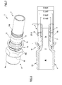
figure 4 is a perspective view of the fitting, and the relative flexible pipe, offigure 3 , and further shows an open blocking pliers in the step of nearing to the fitting to perform the blocking thereof; -
figure 5 is a fitting according to the present invention, blocked on a multi-layer pipe; also visible is the blocking pliers in the operating condition, i.e. closed on the blocking means of the fitting; -
figure 6 is a section view of the fitting offigure 5 and the pipe mounted thereto, on termination of the blocking operations; -
figure 6a is a larger-scale view of a portion of the view offigure 6 ; -
figure 7 is a perspective view of the fitting offigure 5 ; -
figure 8 shows the fitting offigure 1 with the addition of indications of the measurements of some components; -
figure 9 is a larger-scale view of a portion offigure 8 , with the addition of further measurements; -
figure 10 shows a possible embodiment of the blocking means of the fitting of the present invention. With reference to the figures of the drawings, a fitting for connecting pipes T is denoted in its entirety, in particular for connecting flexible pipes, according to the present invention. - The fitting 1 is used for reciprocally connecting pipes T used for transporting pressurised fluid. The pipes T can be of the type made of a single material (for example rubber or plastic), as shown in
figures 1 ,3 and4 , or of the "multilayer" type. Multilayer pipes T are, for example, pips containing superposed layers of different materials in which, in the specific case, one or more of the layers is made of a metal material. For example, as shown by way of example infigures 5 ,6 and7 , the multilayer comprises three superposed layers T1, T2 and T3 (preferably glued to one another by means of intermediate adhesive layers); the external layers T1 and T3 are preferably made of plastic and the intermediate layer (T2 is made of metal material (for example aluminium). - With reference to the embodiment, by way of non-exclusive example, shown in the figures, the fitting 1 comprises a first tubular element (or terminal) 3 and a second
tubular element 4 respective provided with a first3a and a second inlet/outlet opening 4a and defining, internally thereof, respectively a first 3b and asecond conduit 4b. The two tubular elements are connected to one another at respective opposite ends to the respective inlet/outlet opening, such that the first 3b and thesecond conduit 4b are in communication with one another and overall define anassembly conduit 2, which puts the first 3a and thesecond opening 4a in fluid communication with one another. - The fitting 1 is further provided at least with first blocking means 10 comprising a
sleeve 11 and a blockingring 15. Thesleeve 11 is associable, preferably removably, to the firsttubular element 3 in such a way as to surround it externally and create, between thesleeve 11 and the first tubular element, anannular housing 12 destined to insertingly receive a pipe T; once the insertion has taken place the pipe is interposed between the first tubular element and the sleeve. The sleeve has aninternal surface 11a, facing towards the firsttubular element 3, and anexternal surface 11b; it is further provided with at least anannular protrusion 13, which extends from the external surface, and at least anannular gully 14 fashioned in the internal surface at theannular protrusion 13. The blockingring 15 is housable in theannular gully 14. - The first blocking means 10 are configured to operate in an inserting configuration, in which they enable insertion of the pipe T in the
annular housing 12, and in a blocked configuration, in which they stably and fluid-sealingly block the pipe in the annular housing. - In more detail, the passage of the first blocking means 10 from the insertion configuration to the blocking configuration occurs by means of a radial deformation of the
sleeve 11, nearingly to the firsttubular element 3, such as to compress the pipe T between the sleeve and the first tubular element internally of the annular housing. This deformation is realized by acting on theexternal surface 11b of the sleeve with a clamping profile P1 of a clamping pliers P (visible infigures 4 and5 ), able to plastically deform the sleeve. In other words, the passage of the blocking means into the blocking configuration determines a reduction of the radial extension of theannular housing 12, caused by the nearing of thesleeve 11 to the firsttubular element 3, and a consequent compression of the pipe T internally of the annular housing. - In the embodiment shown in the figures, the blocking means 10 are illustrated with reference to the first tubular element (or terminal) 3. The blocking means may of course be replicated for the second tubular element (or terminal) 4 (for blocking the respective pipe) and possible for further tubular elements of the fitting.
- The first
tubular element 3 and thesleeve 11 preferably have a hollow cylindrical conformation and exhibit a same longitudinal development axis X. - As visible in particular in
figures 1 ,3 ,8 ,9 and 10 , the blockingring 15 is housed in theannular gully 14 of thesleeve 11 in such a way as to be substantially flush with theinternal surface 11a of the sleeve, i.e. to realize aninternal surface 11 of the sleeve that is substantially cylindrical. In other words the diameter of the internal surface of the sleeve (housing the ring 15) is constant along the whole development of the sleeve along the longitudinal development axis X. - In a preferred embodiment, the
annular protrusion 13 and theannular gully 14 are made in a same position of thesleeve 11 along the longitudinal development axis X. The correspondence between the protrusion and the gully (respectively externally and internally of the sleeve) is linked both to the correct functioning of the blocking means (as it is the protrusion which presses on the underlying ring, the ring having to be aligned therewith) and to the manufacturing process of the sleeve (which advantageously occurs by means of a single deformation which creates the annular protrusion and gully). - The
annular protrusion 13 and theannular gully 14 are substantially complementary, one being the "negative" of the other; the thickness (or external volume) of the protrusion, calculated as the distance from theexternal surface 11b of the sleeve, substantially corresponds to the depth of thegully 14; in other words, the addition of material on the external surface of the sleeve corresponds to the lack of material on the internal surface. - The first
tubular element 3 comprises at least afirst seal element 7, externally enveloped on the tubular element such as to be interposed between it and a pipe T inserted in theannular housing 12. Thefirst seal element 7 is able to deform, when the first blocking means 10 are in the blocked configuration, in order to inhibit a fluid communication between thefirst conduit 3b and an external surface of the firsttubular element 3. Theseal element 7 is elastic; in particular, it is a seal having an appropriately shaped section. - The
annular protrusion 13 and theannular gully 14 are preferably realised in a position of thesleeve 11, along the longitudinal development axis X, at the position occupied by the first seal element on the tubular element; in other words, the annular protrusion and the annular gully are aligned along a perpendicular plane to the longitudinal development axis X. Thesleeve 11 preferably has a thickness, calculated as the distance between theinternal surface 11a and theexternal surface 11b, that is substantially uniform over the whole longitudinal development thereof. - When the first blocking means 10 are in the blocked configuration, the deforming thrust of the
sleeve 11 preferably determines a radial nearing to the firsttubular element 3 by theannular protrusion 13 and the blockingring 15, housed in theannular gully 14; this thrust transmits through the blockingring 15 to the underlying portion of pipe T at thefirst seal element 7, determining a deformation of thefirst seal element 7 and a sealed blocking of the pipe on the first tubular element. - The blocking
ring 15 can be a closed ring, with a toroidal conformation, or, alternatively, a ring provided with a cut. By way of example, the cut of the ring is parallel to a central axis of the ring. The blocking ring is preferably made of rubber or a plastic material. - The blocking
ring 15 preferably has an external diameter that substantially corresponds to the diameter of the bottom of theannular ring 14, such that when it is inserted therein it is maintained stably internally of the gully by effect of the snug interference with the lateral walls of the gully. In substance, thering 15 has a diameter that is such as to precisely occupy theannular gully 14 without accidentally exiting therefrom. During the assembly step, the blocking ring is deformed such as to be insertable internally of the sleeve, and when it reaches the annular gully it is free to return to the initial shape thereof and thus occupy the annular gully. Additionally, or alternatively, the blocking ring is maintained in the annular gully by gluing. - When the blocking ring comprises a cut making it discontinuous along the circumferential development thereof, it preferably has an elasticity that is such as to determine, when it is flexed by nearing or distancing the ends at the cut position, the development of an elastic force tending to return it into a rest configuration. This elasticity enables easy mounting of the ring: in fact it is deformed during the insertion in the sleeve and, on reaching the annular gully, the elasticity reopens it so that it occupies the gully; this elasticity further maintains it stably in contact with the bottom surface of the annular gully without any need to perform other operations.
- The presence of the cut in the ring does not influence the correct functioning of the blocking means, as the discontinuity introduced by the cut is a minimum part of the whole ring and what is more the cut tends to close when the ring is inserted in the gully, with the result that the two edges of the ring (created with the cut) tend to return into contact with one another, thus re-establishing the circumferential continuity of the
ring 15. - The blocking ring preferably has a radial thickness (calculated as the difference between the external diameter thereof and the internal diameter thereof) comprised between 0.3mm and 3mm or comprised between 0.8mm and 1.6mm, preferably about 1.2mm.
- As can be seen in the figures, the first
tubular element 3 comprises a plurality ofribs 9 extending externally of the tubular element and having a substantially annular profile; the ribs define a plurality of grips for the pipe when the first blocking means are in the blocking configuration. In greater detail, theribs 9 extend radially from the external surface of the first tubular element over a rib diameter that is greater than an external diameter of the firsttubular element 3. - As illustrated in particular in
figures 1, 2 ,3 ,8 and9 , thefirst sealing element 7 is enveloped externally of the first tubular element, between two adjacent ribs, such as to be comprised radially within the rib diameter or such as to be substantially flush with the development of theribs 9. - The
first sealing element 7 is positioned between twoadjacent ribs 9 so as not to interfere with a pipe T inserted in theannular housing 12 and such that (as previously illustrated) it does not realise a fluid seal between the firsttubular element 3 and the pipe T when the firstgripping means 10 are in the insertion configuration (with the aim of being able to detect a missed blocking of the fitting). On the contrary, when the first blocking means are in the blocked configuration, the combined action of the plurality ofribs 9 and the radial compression of thesleeve 11 towards the firsttubular element 3 prevents de-insertion of the pipe T from theannular housing 12. - When the first
gripping means 10 are in the blocking configuration and thesleeve 11 is deformed towards the firsttubular element 3, the compression of the pipe T on the plurality ofribs 9 advantageously determines a deformation of the pipe by action of the plurality of fibs (clearly visible infigures 5 ,6 and 6a ) with a consequent jointing of the pipe on the ribs. - The blocking
ring 15 preferably has a width, measured parallel to the longitudinal development axis X, comprised between 2mm and 4mm or comprised between 2.5mm and 3.5mm or comprised between 2.8mm and 3.2mm, preferably about 3mm. - The
annular gully 14 preferably has a respective width, measured parallel to the longitudinal development axis X, comprised between 2mm and 6mm or comprised between 3mm and 5mm, preferably about 4mm. In this way the annular gully might not be completely filled between the two lateral walls thereof by the blocking ring, but instead can maintain, on one or both sides of the blocking ring, a free space (seefigures 1 ,3 ,8 ,9, 10 ). This space can be filled by the blocking ring when, by effect of the passage of the blocking means into the blocked configuration (i.e. the deformation of the sleeve), the ring undergoes a deformation by crushing that extends the width thereof; this crushing of the seal ring (and the relative axial "filling" of the annular gully) is shown infigures 6 and 6a . - As shown in the embodiment of the figures, the first
tubular element 3 preferably comprises asecond sealing element 8, substantially identical to thefirst sealing element 7, wound externally of the first tubular element in a different position along the longitudinal development axis X. The first and the second seal element preferably have a toroidal shape, and are both preferably 0-rings, widely known and used in the sector. - The presence of two sealing elements increases the seal of the fitting, the effectiveness of the blocking and the duration thereof over time.
- The
annular protrusion 13 and theannular gully 14 of the sleeve are preferably realised in a position of thesleeve 11 along the longitudinal development axis X, intermediate with respect to the positions occupied by the first and the second sealing element on the tubular element, such that when the first blocking means are in the blocked configuration, the thrust of the blockingring 15 on the underlying portion of pipe T determines a deformation of the first 7 and thesecond sealing element 8 and a sealed blocking of the pipe on the first tubular element. - The annular gully and the blocking ring cannot extend indefinitely in width, between the longitudinal ends of the sleeve, although preferably they are maintained within a width limit fixable at about 10mm. in general, the annular gully occupies a substantially median position along the development of the sleeve with respect to the longitudinal axis X. The annular gully is preferably straddling one or both the sealing elements, as shown by way of example in
figures 1 ,3 ,8 and9 . In substance, theannular gully 14 interests the overlying zone comprised between the two sealingelements tubular element 3 preferably exhibits, at the opposite end to the first inlet/outlet opening 3a, anabutting element 3c which extends distancingly from the external surface of the first tubular element and is able to define an abutting surface for a pipe T splined on the tubular element. The abutting element has a radial dimension that is greater than the external surface of the first tubular element, measured distancingly from the longitudinal development axis X. - The first
tubular element 3 preferably comprises anassembly portion 3d and the first blocking means 10 comprise a sleeve-bearing element 16 (preferably distinct from the sleeve (11) removably associable to the assembly portion; this sleeve-bearing element is configured to assembly thesleeve 11 to the firsttubular element 3 in such a way that the sleeve stably surrounds the first tubular element and defines theannular housing 12. The sleeve-bearingelement 16 preferably has an annular conformation and, when associated to the assembly portion, exhibits a central axis coinciding with the longitudinal development axis X. The sleeve-bearing element preferably extends along the central axis between a first annularengaging end 16a to the assembly portion of the first tubular element and a second annularengaging end 16b able to receive the sleeve. Theassembly portion 3d of the first tubular element is preferably positioned at theabutting element 3c and consists of an annular gully (seefigures 2 and8 ). The assembly of the sleeve (associated to the sleeve-bearing element) to the tubular element3 preferably occurs with a press-fit by insertion of the first annularengaging end 16a into the gully defining theassembly portion 3d. - The sleeve extends, along the longitudinal development axis X, between a
first end 11c, destined to be mounted to the firsttubular element 3, and asecond end 11 d, opposite the first end, free and defining an opening for insertion of the pipe T in the annular housing. - The first end of the sleeve is preferably associable to the sleeve-bearing
element 16, in particular the second annularengaging end 16b. Thesecond end 11d preferably comprises a lead-in (for example a flaring towards the outside) to facilitate the insertion of the end of the pipe to be connected. - The sleeve-bearing element preferably comprises one or
more openings 16c fashioned in one or more circumferential positions of the sleeve-bearing element and passing between the outside and inside of the sleeve-bearing element; these openings (overall defining a window-type hatch about the sleeve-bearing element) enable the observation (from outside the sleeve) of the pipe T inserted in thehousing 12 with the aim of verifying the correct positioning of the pipe before proceeding to the blocking thereof in the fitting. - The fitting 1 can comprise second blocking means, for example identical to the first blocking means 10 and destined to cooperate with a second tubular element in order to block a further pipe T. In this case the second blocking means comprise a respective sleeve (with annular protrusion and gully) and a respective blocking ring.
- Alternatively, as shown in the embodiment of the figures, the second
tubular element 4 of the fitting 1 comprises (in the place of second blocking means) connecting means 20 to a fluid source, for example a conduit, a tap or a tank (not shown and of known type). The connecting means preferably comprise a threaded portion destined to connect to a corresponding counter-thread of the fluid source such as to set the secondtubular element 4 in fluid communication with the fluid source. The connecting means 20 preferably comprise a manoeuvring portion M engageable by a screwing tool. The manoeuvring portion M is generally a hexagonal projection, having a radial dimension that is greater than a the tubular element and able to be manoeuvred with a wrench to realize a sufficiently tight fastening of the device to the fluid source. The manoeuvring portion M is preferably realized on theabutting element 3c, such as to define a grip of the fitting 1 and at the same time be engaged to a screwing tool 1. - In a possible embodiment of the invention (not shown) the fitting preferably comprises a plurality of tubular elements in fluid communication with one another, a respective pipe being splinable on each of the tubular element, each tubular element being preferably identical to the first or second tubular element.
- The first 3 and/or the second
tubular element 4 are preferably made of metal, preferably brass (for example yellow brass CW602N) or steel, or of plastic material (for example technopolymer PPSU). Thesleeve 11 is made of a metal material, preferably steel (for example stainless steel AISI 304). The blockingring 15 is preferably made of plastic or rubber or metal. The sealingelements - The fitting of the present invention conforms to standards for use with potable water. By way of example, the maximum working temperature can be 120°C in continuous functioning and the maximum working pressure is 10 bar.
- The embodiment shown in the figures illustrates a fitting having a linear conformation, in which the first and the second tubular element have the respective longitudinal extension axes coinciding with one another. However the fitting of the present invention can have an angular conformation, i.e. the respective longitudinal development axes of the first and the second tubular element form, with one another, an angle which is not 180°, for example 45° or 90°. The angle between the tubular elements does not influence the technical characteristics described, nor the functioning of the fitting, although it enables arranging the different fittings usable in a plant in accordance with the angle between the pipes to be connected.
- The fitting can also have a T conformation and comprise three tubular elements of which two external tubular elements aligned to one another and third intermediate tubular element interposed between the two external tubular elements and perpendicular thereto.
- The
sleeve 11 of the present invention is configured to be blocked by means of pliers having a clamping profile of type B or type F or type H or type TH or type U, with reference to clamping standards of known type in the hydraulic sector. This means that the position of theannular protrusion 13 and theannular gully 14 are such as to enable a correct blocking with each of the pliers (with clear advantages in terms of possibility of use of the fitting). In substance, the sleeve is conformed such that with each of the pliers the deformation of the blocking means is of the correct entity, i.e. neither insufficient (in which case there would be seal problems) nor excessive (in which case the pipe might be damaged). -
Figures 8 and9 illustrate a series of sizes, by way of example, for the fitting of the present invention. - The dimensions are for a fitting structured to house a pipe T having a determined diameter. It is obviously possible to realize fittings for pipes of each diameter, by appropriately proportioning the dimensions of the single components (for example proportioning the dimensions shown in the figures.
Figure 10 in particular illustrates the first blocking means 10. The dimension denoted by letter A indicates the width of the seal ring, the size denoted by letter B indicates the internal diameter of the sleeve and the size denoted by letter C indicates the external diameter of the sleeve (calculated as the radial dimension of the protrusion 13). - The following table reports, by way of example, constructional values for sizes A, B and C for some fittings of different dimensions (further diameters might be included):
Pipe measurement A B C 16/2 3 Ø16.3 Ø18.9 20/2 3 Ø20.3 Ø22.9 26/3 3 Ø26.3 Ø28.9 32/3 3 Ø32.3 Ø35.1 - The described fitting can be subjected to variants and modifications, all falling within the protective scope of the present invention. For example, several annular protrusions can be included (for example two or three) in distinct positions of the sleeve and corresponding annular gullies with blocking rings.
- The production method of a fitting according to the present invention comprises steps of:
- predisposing the first and second tubular element as described above;
- predisposing a sleeve having a hollow cylindrical conformation and exhibiting a longitudinal development axis;
- realising the annular protrusion on the external surface of the sleeve;
- realising the annular protrusion on the internal surface of the sleeve;
- predisposing the blocking ring and housing it in the annular gully;
- assembling the sleeve on the first tubular element such as to surround it externally and creating the annular housing destined to receive a pipe by insertion.
- The step of realising the annular protrusion and realising the annular gully are advantageously carried out contemporaneously by means of a single plastic deforming operation of the sleeve. The step of predisposing the blocking ring preferably includes realizing a closed blocking ring having a toroidal conformation (typically in the case of a rubber blocking ring), or realizing a closed ring and thus cut the ring (preferably in the case of a plastic blocking ring).
- In use, the first
tubular element 3 is predisposed with thefirst sealing element 7 and possibly thesecond sealing element 8 located in the respective seatings between two adjacent ribs. Thereafter, thetubular element 3 is inserted internally of the terminal section of a pipe T, such that theribs 9 can act on the pipe and retain it couplingly with the tubular element and the sleeve externally envelops the terminal section of the pipe. - Thereafter, for example by means of a pliers P, provided with a clamping profile P1, compression actions are generated on the
sleeve 10 at one or more portions of the sleeve, which undergo a permanent deformation which crushes the pipe T on the underlyingtubular element 3, and consequently generates a compression on the interposedsealing element 7 which maintains it in the deformed position. The same occurs for thesecond sealing element 8. - Note that the pipe obviously undergoes a deformation, preferably permanent (in particular in the case of a multilayer pipe).
- Note further (
figures 6 and7 ) that the effective action of the pliers P, pressing on the outside of thesleeve 11, determines a "flattening" of theprotrusion 13. In substance theprotrusion 13 has been radially deformed towards the inside of the tubular element and this has the effect of correspondingly thrusting on the sealingring 15 and on the underlying pipe T (as well as on thesealing elements 7 and 8). This result is clearly visible infigure 6a . - In the described fitting, the presence of the sleeve in the annular protrusion and the underlying blocking ring enables locally availing of a surplus of material for pressing the underlying sealing element; this increase in material is necessary for operating with seals which do not project from the ribs (and which thus enable detection of the missed blocking of the fitting); without the blocking ring the drawback of the prior art would result, as there would be a "gap" at the position of the protrusion on the internal side of the sleeve, which would prevent transfer of the thrust from the pipe to the underlying sealing element, with a consequent poor seal even with the fitting tightly fastened.
- In the present invention the sleeve has been acted on by modifying the structure thereof, without any need for modifications to the clamping profile of the pliers. In particular, at the productive level, a "classic" sleeve can be taken (i.e. of known type, meaning smooth and uniformly cylindrical on both internal and external sides) and modified by plastically deforming it such as to create the annular gully (a space) internally thereof and the corresponding annular protrusion externally thereof; then the sealing ring is inserted into the gully with the function of a washer (or filling material).
- It is further possible, with a consequent reduction in costs, to use seals (for example 0-rings) of entirely conventional type, simply by selecting them with a diameter of less than the diameter of the ribs.
- The use of conventional 0-rings (i.e. with a constant section) has the further advantage given the fact that no intrinsic structural pre-weakening is performed on the seals, which are dimensioned optimally and therefore exhibit optimum resistance and elasticity characteristics, as they do not exhibit any yielding or pre-weakened points. It follows that due to the absence of pre-weakening points in the seals, the fitting exhibits a working duration that is greater with respect to the seals of the prior art described above, and in particular enables guaranteeing a fluid seal for a longer time, including following stressful thermal and pressure cycles to which fluid plants are normally subject.
Claims (10)
- A fitting (1) for connecting pipes (T), in particular at least a pipe of the pipes being flexible, comprising:- at least a first tubular element (3) provided, at an end thereof, with a first inlet/outlet opening (3a) and defining internally 5 thereof a first conduit (3b);- at least a second tubular element (4) provided, at an end thereof, with a second inlet/outlet opening (4a) and defining internally thereof a second conduit (4b),
said first tubular element (3) and second tubular element (4) being connected with one another, at respective ends opposite to the respective inlet/outlet opening, such that said first conduit (3b) and second conduit are in communication with one another and overall define an assembly conduit (2), putting said first opening (3a) and said second opening (4a) in fluid communication,
the fitting further comprising at least first blocking means (10) comprising:- a sleeve (11) associable to the first tubular element (3) such as to surround the first tubular element (3) externally and to create, between the sleeve (11) and the first tubular element (3), an annular housing (12) destined to insertingly receive a pipe (T), the pipe (T) being interposed between the first tubular element and the sleeve, said sleeve having an internal surface (11a), facing towards the first tubular element (3), and an external surface (11b), and being provided with at least an annular protrusion (13) extending from said external surface and with at least an annular gully (14) afforded in said internal surface at said annular protrusion (13);- at least a blocking ring (15) housable in said at least an annular gully (14) of said sleeve (11);
said first blocking means (10) being configured for operating at least in an insertion configuration, in which they enable insertion of a pipe (T) into said annular housing (12), and a blocked configuration, in which they stably and fluid-sealingly block the pipe in the annular housing. - The fitting (1) of the preceding claim, wherein the passage of the first blocking means (10) from the insertion configuration to the blocking configuration occurs by means of a radial deformation of the sleeve (11), nearingly to the first tubular element (3), such as to compress the pipe (T) between the sleeve (11) and the first tubular element (3) internally of the annular housing (12), the deformation being realised by acting on the external surface (11b) of the sleeve with a clamping profile (P1) of a blocking pliers (P), able to plastically deform the sleeve, and/or wherein the passage of the blocking means (10) into the blocking configuration determines a reduction of the radial extension of the annular housing (12), caused by a nearing of the sleeve (11) to the first tubular element (3), and a consequent compression of the pipe (T) internally of the annular housing.
- The fitting (1) of claim 1 or 2, wherein the first tubular element (3) and the sleeve (11) have a hollow cylindrical conformation and have a same longitudinal 10 development axis (X), and/or wherein said blocking ring (15) is housed in said annular gully (14) of the sleeve (11) in such a way as to be substantially flush with the internal surface (11a) of the sleeve and/or such as to realise an internal surface (11a) of the sleeve that is substantially cylindrical and/or has a constant diameter along the whole development of the sleeve along the longitudinal development axis (X), and/or wherein said annular protrusion (13) and said annular gully (14) are realised substantially in a same position of the sleeve (11) along the longitudinal development axis (X).
- The fitting (1) of any one of the preceding claims, wherein the first tubular element (3) comprises at least a first sealing element (7), externally enveloping the tubular element in such a way as to be interposed between the tubular element and a pipe (T) inserted in said annular housing (12), said first sealing element (7) being deformable, when the first blocking means (10) are in the blocking configuration, such as to inhibit a fluid communication between the first conduit (3b) and an external surface of the first tubular element, and/or wherein said annular protrusion (13) and said annular gully (14) are realised in a position of the sleeve (11), along said longitudinal axis development (X), that is close to, or at, the position occupied by the first sealing element (7) on the tubular element (3), or the annular protrusion and the annular gully are substantially aligned along a plane that is perpendicular to the longitudinal development axis, and/or wherein the first tubular 30 element comprises a second sealing element (8), substantially identical to the first sealing element, enveloped externally of the first tubular element in a different position along the longitudinal development axis.
- The fitting (1) of any one of the preceding claims, wherein the sleeve has a thickness, calculated as the distance between the internal surface and the external surface, that is substantially uniform over a whole longitudinal development thereof, and/or wherein the blocking ring is a closed ring, having a toroidal conformation, or, alternatively, it is a ring provided with a cut, and/or wherein the first tubular element comprises a plurality of ribs (9), extending externally of the tubular element and having a substantially annular profile, the ribs defining a plurality of grips for the pipe when the first blocking means are in the blocking configuration, and/or wherein the ribs extend radially from the external surface of the first tubular element over a rib diameter that is greater than an external diameter of the first tubular element,
and/or wherein the first sealing element is enveloped externally of the first tubular element, between two adjacent ribs of the plurality of ribs, such as to be comprised radially within the rib diameter or such as to be substantially flush with the development of the ribs, and/or wherein the first sealing element is positioned between two adjacent ribs such as not to interfere with a pipe inserted in the annular housing and such as not to realise a fluid seal between the first tubular element and the pipe when the first blocking means are in the inserting configuration. - The fitting (1) of any one of the preceding claims, further comprising second blocking means including:- a respective sleeve associated to the second tubular element in such a way as to surround it externally and to create, between the sleeve and the second tubular element, a respective annular housing destined to insertingly receive a pipe, the pipe being interposed between the second tubular element and the sleeve, said respective sleeve having an internal surface, facing towards the second tubular element, and an external surface, and being provided with at least an annular protrusion extending from the external surface and at least an annular gully fashioned in the internal surface at the annular protrusion;- a respective blocking ring housable in the at least an annular gully of the sleeve;said second blocking means being preferably identical to the first blocking means and/or provided with one or more of the characteristics described in the aspects and/or in the claims in relation to the first blocking means.
- The fitting (1) of any one of the preceding claims, wherein said second tubular element comprises connecting means (20) to a fluid source, for example a conduit, a tap or a tank, and/or wherein the connecting means comprise a threaded portion destined to connect to a corresponding counter-thread of the fluid source such as to set the second tubular element in fluid communication with the fluid source, and/or wherein the fitting comprises a plurality of tubular elements in reciprocal fluid communication, each tubular element being preferably identical to the first or second tubular element.
- A production method of a fitting for connecting pipes, in particular flexible pipes, the method comprising steps of:- predisposing at least a first tubular element provided, at an end thereof, with a first inlet/outlet opening and defining internally thereof a first conduit;- predisposing at least a second tubular element provided, at an end thereof, with a second inlet/outlet opening and defining internally thereof a second conduit;
the first and second conduit being connected to one another, at respective opposite ends, to the respective inlet/outlet opening, such that the first and second conduit are in communication with one another and overall define an assembled conduit of the fitting that sets the first opening and the second opening in fluid communication,- predisposing a sleeve having a hollow cylindrical conformation and exhibiting a longitudinal axis of development;- realising, on an external surface of the sleeve, at least an annular protrusion extending from the external surface;- realising, on an internal surface of the sleeve, at the annular protrusion, at least an annular gully having a determined depth;- predisposing a blocking ring, preferably having a thickness that is substantially equal to said determined depth of the annular gully;- housing the blocking ring in the annular gully of the sleeve;- mounting the sleeve to the first tubular element in such a way as to surround it externally and to create, between the internal surface of the sleeve and the first tubular element, an annular housing destined to insertingly receive a pipe, the pipe being interposed between the first tubular element and the sleeve. - The method of the preceding claim, wherein the steps of realising, on an external surface of the sleeve, at least an annular protrusion and realising, on an internal surface of the sleeve, at least an annular gully, are performed contemporaneously by means of an operation of plastic deformation of the sleeve, the plastic deformation of the sleeve being preferably obtained by means of a moulding and/or forming and/or mechanical working operation.
- The method of claim 8 or 9, wherein the step of predisposing a blocking ring comprises at least a step of realising a closed blocking ring, having a toroidal conformation, and optionally an additional step of cutting the ring such as to interrupt the circumferential continuity of the ring, and/or wherein the step of housing the blocking ring in the annular gully of the sleeve occurs before or after the step of mounting the sleeve to the first tubular element, and/or wherein the method comprises, preferably before the step of mounting the sleeve to the tubular element, a step of predisposing at least a sealing element, preferably two sealing elements, and enveloping it externally of the first tubular element in such a way that the sealing element is interposed between the first tubular element and a pipe inserted in the annular housing, the sealing element being preferably a seal or an 0-ring, and/or wherein the steps of realising, on an external surface of the sleeve, at least an annular protrusion, and realising on an internal surface of the sleeve at least an annular gully are carried out on a same portion of the sleeve, along the longitudinal axis of development, and/or such that the annular protrusion and the annular gully are at the position occupied by the at least a sealing element on the tubular element.
Priority Applications (2)
| Application Number | Priority Date | Filing Date | Title |
|---|---|---|---|
| SI201330082T SI2677223T1 (en) | 2012-06-19 | 2013-06-07 | Fitting for connecting pipes, in particular flexible pipes |
| PL13171013T PL2677223T3 (en) | 2012-06-19 | 2013-06-07 | Fitting for connecting pipes, in particular flexible pipes |
Applications Claiming Priority (1)
| Application Number | Priority Date | Filing Date | Title |
|---|---|---|---|
| IT001068A ITMI20121068A1 (en) | 2012-06-19 | 2012-06-19 | FITTING FOR THE CONNECTION OF PIPES, IN PARTICULAR OF FLEXIBLE PIPES |
Publications (2)
| Publication Number | Publication Date |
|---|---|
| EP2677223A1 true EP2677223A1 (en) | 2013-12-25 |
| EP2677223B1 EP2677223B1 (en) | 2015-08-05 |
Family
ID=46727354
Family Applications (1)
| Application Number | Title | Priority Date | Filing Date |
|---|---|---|---|
| EP13171013.9A Active EP2677223B1 (en) | 2012-06-19 | 2013-06-07 | Fitting for connecting pipes, in particular flexible pipes |
Country Status (9)
| Country | Link |
|---|---|
| EP (1) | EP2677223B1 (en) |
| DK (1) | DK2677223T3 (en) |
| ES (1) | ES2550498T3 (en) |
| HU (1) | HUE028010T2 (en) |
| IT (1) | ITMI20121068A1 (en) |
| PL (1) | PL2677223T3 (en) |
| RS (1) | RS54304B1 (en) |
| RU (1) | RU2556944C2 (en) |
| SI (1) | SI2677223T1 (en) |
Cited By (6)
| Publication number | Priority date | Publication date | Assignee | Title |
|---|---|---|---|---|
| DE102017210844A1 (en) | 2017-06-27 | 2018-12-27 | Fränkische Rohrwerke Gebr. Kirchner Gmbh & Co. Kg | compression sleeve |
| IT201900002345A1 (en) | 2019-02-18 | 2020-08-18 | Ivar Spa | FITTING FOR THE CONNECTION OF PIPES, IN PARTICULAR OF FLEXIBLE HOSES |
| IT201900006496A1 (en) | 2019-05-02 | 2020-11-02 | Ivar Spa | FITTING FOR THE CONNECTION OF PIPES, IN PARTICULAR OF FLEXIBLE HOSES |
| JP2021516321A (en) * | 2018-01-24 | 2021-07-01 | ザルトリウス ステディム ノース アメリカ インコーポレイテッド | Fluid transfer assembly |
| IT202100006860A1 (en) * | 2021-03-22 | 2022-09-22 | Valsir S P A A Socio Unico | ADJUSTABLE JOINT, ESPECIALLY FOR CONNECTING TWO PIPES THROUGH A STRUCTURE |
| JP7427916B2 (en) | 2019-10-31 | 2024-02-06 | セイコーエプソン株式会社 | Channel member, channel unit, and liquid injection device |
Families Citing this family (5)
| Publication number | Priority date | Publication date | Assignee | Title |
|---|---|---|---|---|
| WO2020124123A1 (en) * | 2018-12-19 | 2020-06-25 | Mainset Pty Ltd | Plumbing fitting |
| EP4025292A4 (en) | 2019-09-06 | 2023-04-19 | Sartorius Stedim North America Inc. | Separable fluid transfer connector |
| DE102020130213A1 (en) * | 2020-11-16 | 2022-05-19 | Fränkische Industrial Pipes GmbH & Co. KG | fluid connection unit |
| AU2021399776A1 (en) * | 2020-12-17 | 2023-07-20 | REHAU Industries SE & Co. KG | Connecting element system for producing a tube connection, tube connection comprising the former, and method for producing a tube connection of this type |
| DE202020107328U1 (en) * | 2020-12-17 | 2022-03-18 | REHAU Industries SE & Co. KG | Pipe connection and connecting element for producing a pipe connection |
Citations (5)
| Publication number | Priority date | Publication date | Assignee | Title |
|---|---|---|---|---|
| US2250286A (en) * | 1937-09-27 | 1941-07-22 | United Metal Hose Company Inc | Hose coupling |
| GB554002A (en) * | 1942-02-04 | 1943-06-15 | Walter Arthur Melsom | Improvements in and relating to flexible hose couplings |
| US6581982B1 (en) * | 1997-11-03 | 2003-06-24 | Novopress Gmbh Pressen Und Presswerkzeuge & Co., Kg | Method for connecting a pipe and a pipe coupling, link between a pipe and a pipe coupling, and connector used |
| EP1653142A1 (en) | 2004-10-28 | 2006-05-03 | FRÄNKISCHE ROHRWERKE GEBR. KIRCHNER GmbH & Co KG | Press-fitting |
| US20100123310A1 (en) * | 2008-11-20 | 2010-05-20 | Marvin Miller | Crimpable or swageable fluid power ferrules, couplings, systems and methods |
Family Cites Families (4)
| Publication number | Priority date | Publication date | Assignee | Title |
|---|---|---|---|---|
| DE10137078B8 (en) * | 2001-07-28 | 2005-04-14 | Uponor Innovation Ab | Press fitting for pipes |
| RU2098711C1 (en) * | 1995-09-13 | 1997-12-10 | Константин Менделевич Бронзман | Permanent joint of high-pressure hose with connecting fittings |
| EP1096194B1 (en) * | 1999-10-28 | 2003-12-03 | Uponor Innovation Ab | Compression fitting for a pipe |
| DE10010573C1 (en) * | 2000-03-03 | 2001-03-01 | Unicor Rohrsysteme Gmbh | Pipe end closure device has pipe fitting body provided with support sleeve fitting into pipe enclosed by compression sleeve fitted around pipe end |
-
2012
- 2012-06-19 IT IT001068A patent/ITMI20121068A1/en unknown
-
2013
- 2013-06-07 SI SI201330082T patent/SI2677223T1/en unknown
- 2013-06-07 DK DK13171013.9T patent/DK2677223T3/en active
- 2013-06-07 PL PL13171013T patent/PL2677223T3/en unknown
- 2013-06-07 EP EP13171013.9A patent/EP2677223B1/en active Active
- 2013-06-07 RS RS20150683A patent/RS54304B1/en unknown
- 2013-06-07 ES ES13171013.9T patent/ES2550498T3/en active Active
- 2013-06-07 HU HUE13171013A patent/HUE028010T2/en unknown
- 2013-06-17 RU RU2013127175/06A patent/RU2556944C2/en active
Patent Citations (5)
| Publication number | Priority date | Publication date | Assignee | Title |
|---|---|---|---|---|
| US2250286A (en) * | 1937-09-27 | 1941-07-22 | United Metal Hose Company Inc | Hose coupling |
| GB554002A (en) * | 1942-02-04 | 1943-06-15 | Walter Arthur Melsom | Improvements in and relating to flexible hose couplings |
| US6581982B1 (en) * | 1997-11-03 | 2003-06-24 | Novopress Gmbh Pressen Und Presswerkzeuge & Co., Kg | Method for connecting a pipe and a pipe coupling, link between a pipe and a pipe coupling, and connector used |
| EP1653142A1 (en) | 2004-10-28 | 2006-05-03 | FRÄNKISCHE ROHRWERKE GEBR. KIRCHNER GmbH & Co KG | Press-fitting |
| US20100123310A1 (en) * | 2008-11-20 | 2010-05-20 | Marvin Miller | Crimpable or swageable fluid power ferrules, couplings, systems and methods |
Cited By (12)
| Publication number | Priority date | Publication date | Assignee | Title |
|---|---|---|---|---|
| DE102017210844A1 (en) | 2017-06-27 | 2018-12-27 | Fränkische Rohrwerke Gebr. Kirchner Gmbh & Co. Kg | compression sleeve |
| WO2019002323A1 (en) | 2017-06-27 | 2019-01-03 | Fränkische Rohrwerke Gebr. Kirchner Gmbh & Co. Kg | Press-fit sleeve |
| CN110462274A (en) * | 2017-06-27 | 2019-11-15 | 法兰克管厂基希讷兄弟有限两合公司 | Pressing sleeve |
| RU2721497C1 (en) * | 2017-06-27 | 2020-05-19 | ФРЕНКИШЕ РОРВЕРКЕ ГЕБР. КИРХНЕР ГМБХ унд КО. КГ | Press bushing |
| JP2021516321A (en) * | 2018-01-24 | 2021-07-01 | ザルトリウス ステディム ノース アメリカ インコーポレイテッド | Fluid transfer assembly |
| US11506310B2 (en) | 2018-01-24 | 2022-11-22 | Sartorius Stedim North America Inc. | Fluid transfer assembly |
| IT201900002345A1 (en) | 2019-02-18 | 2020-08-18 | Ivar Spa | FITTING FOR THE CONNECTION OF PIPES, IN PARTICULAR OF FLEXIBLE HOSES |
| CN113508256A (en) * | 2019-02-18 | 2021-10-15 | I.V.A.R.股份有限公司 | Fitting for connecting pipes, in particular flexible pipes |
| CN113508256B (en) * | 2019-02-18 | 2023-07-21 | I.V.A.R.股份有限公司 | Fitting for connecting flexible pipes and method for manufacturing same |
| IT201900006496A1 (en) | 2019-05-02 | 2020-11-02 | Ivar Spa | FITTING FOR THE CONNECTION OF PIPES, IN PARTICULAR OF FLEXIBLE HOSES |
| JP7427916B2 (en) | 2019-10-31 | 2024-02-06 | セイコーエプソン株式会社 | Channel member, channel unit, and liquid injection device |
| IT202100006860A1 (en) * | 2021-03-22 | 2022-09-22 | Valsir S P A A Socio Unico | ADJUSTABLE JOINT, ESPECIALLY FOR CONNECTING TWO PIPES THROUGH A STRUCTURE |
Also Published As
| Publication number | Publication date |
|---|---|
| ITMI20121068A1 (en) | 2013-12-20 |
| HUE028010T2 (en) | 2016-11-28 |
| EP2677223B1 (en) | 2015-08-05 |
| RU2013127175A (en) | 2014-12-27 |
| PL2677223T3 (en) | 2015-12-31 |
| ES2550498T3 (en) | 2015-11-10 |
| RU2556944C2 (en) | 2015-07-20 |
| RS54304B1 (en) | 2016-02-29 |
| DK2677223T3 (en) | 2015-10-26 |
| SI2677223T1 (en) | 2015-12-31 |
Similar Documents
| Publication | Publication Date | Title |
|---|---|---|
| EP2677223B1 (en) | Fitting for connecting pipes, in particular flexible pipes | |
| CA2358120C (en) | Pipe coupling | |
| EP2379926B1 (en) | Improved pipe coupling seal | |
| DK3027948T3 (en) | PRESSURE FITTING FOR WIRING CONNECTION AND PROCEDURE FOR DETERMINING A FITTING ON A WIRING CONNECTION | |
| CN108291671B (en) | Sprinkler adapter and pipe plug | |
| CA2829660C (en) | Fitting connection including compression nut with retainer | |
| KR101274094B1 (en) | Pipe connecting apparatus of one-touch type | |
| KR20170001915U (en) | Improved gas piping clamp | |
| US11187365B2 (en) | Connector for piping networks | |
| KR101187042B1 (en) | Device for connecting pipe | |
| CN112879701A (en) | Hot-melting type metal annular corrugated pipe (spiral corrugated pipe) connecting method | |
| EP3542093B1 (en) | Hydraulic closure device and hydraulic and measuring test apparatus using said hydraulic closure device | |
| IT202000009817A1 (en) | INTEGRATED JOINT SYSTEM FOR TUBULAR FLUID DISTRIBUTION ELEMENTS | |
| JP6360308B2 (en) | Pipe branching method and branch saddle joint used therefor | |
| KR101181489B1 (en) | Device for connecting pipe | |
| EP4163528A1 (en) | Fitting assembly for pipe connection | |
| ITMI992608A1 (en) | LOCKING DEVICE FOR PRESS FITTINGS FOR PIPES IN GENERAL | |
| KR101181488B1 (en) | Device for connecting pipe | |
| CN112081943A (en) | Integral structure's card pressure formula ball valve |
Legal Events
| Date | Code | Title | Description |
|---|---|---|---|
| PUAI | Public reference made under article 153(3) epc to a published international application that has entered the european phase |
Free format text: ORIGINAL CODE: 0009012 |
|
| 17P | Request for examination filed |
Effective date: 20130705 |
|
| AK | Designated contracting states |
Kind code of ref document: A1 Designated state(s): AL AT BE BG CH CY CZ DE DK EE ES FI FR GB GR HR HU IE IS IT LI LT LU LV MC MK MT NL NO PL PT RO RS SE SI SK SM TR |
|
| AX | Request for extension of the european patent |
Extension state: BA ME |
|
| RIC1 | Information provided on ipc code assigned before grant |
Ipc: F16L 33/207 20060101AFI20140530BHEP |
|
| GRAP | Despatch of communication of intention to grant a patent |
Free format text: ORIGINAL CODE: EPIDOSNIGR1 |
|
| INTG | Intention to grant announced |
Effective date: 20150217 |
|
| GRAS | Grant fee paid |
Free format text: ORIGINAL CODE: EPIDOSNIGR3 |
|
| GRAA | (expected) grant |
Free format text: ORIGINAL CODE: 0009210 |
|
| AK | Designated contracting states |
Kind code of ref document: B1 Designated state(s): AL AT BE BG CH CY CZ DE DK EE ES FI FR GB GR HR HU IE IS IT LI LT LU LV MC MK MT NL NO PL PT RO RS SE SI SK SM TR |
|
| AX | Request for extension of the european patent |
Extension state: BA |
|
| REG | Reference to a national code |
Ref country code: GB Ref legal event code: FG4D |
|
| REG | Reference to a national code |
Ref country code: CH Ref legal event code: EP |
|
| REG | Reference to a national code |
Ref country code: AT Ref legal event code: REF Ref document number: 740920 Country of ref document: AT Kind code of ref document: T Effective date: 20150815 |
|
| REG | Reference to a national code |
Ref country code: IE Ref legal event code: FG4D |
|
| REG | Reference to a national code |
Ref country code: DE Ref legal event code: R096 Ref document number: 602013002495 Country of ref document: DE |
|
| REG | Reference to a national code |
Ref country code: CH Ref legal event code: NV Representative=s name: ING. ALESSANDRO GALASSI C/O PGA SRL, MILANO, S, CH |
|
| REG | Reference to a national code |
Ref country code: DK Ref legal event code: T3 Effective date: 20151023 |
|
| REG | Reference to a national code |
Ref country code: RO Ref legal event code: EPE |
|
| REG | Reference to a national code |
Ref country code: ES Ref legal event code: FG2A Ref document number: 2550498 Country of ref document: ES Kind code of ref document: T3 Effective date: 20151110 |
|
| REG | Reference to a national code |
Ref country code: SE Ref legal event code: TRGR |
|
| REG | Reference to a national code |
Ref country code: NO Ref legal event code: T2 Effective date: 20150805 |
|
| REG | Reference to a national code |
Ref country code: PL Ref legal event code: T3 |
|
| REG | Reference to a national code |
Ref country code: LT Ref legal event code: MG4D |
|
| REG | Reference to a national code |
Ref country code: NL Ref legal event code: FP |
|
| PG25 | Lapsed in a contracting state [announced via postgrant information from national office to epo] |
Ref country code: LV Free format text: LAPSE BECAUSE OF FAILURE TO SUBMIT A TRANSLATION OF THE DESCRIPTION OR TO PAY THE FEE WITHIN THE PRESCRIBED TIME-LIMIT Effective date: 20150805 Ref country code: LT Free format text: LAPSE BECAUSE OF FAILURE TO SUBMIT A TRANSLATION OF THE DESCRIPTION OR TO PAY THE FEE WITHIN THE PRESCRIBED TIME-LIMIT Effective date: 20150805 Ref country code: GR Free format text: LAPSE BECAUSE OF FAILURE TO SUBMIT A TRANSLATION OF THE DESCRIPTION OR TO PAY THE FEE WITHIN THE PRESCRIBED TIME-LIMIT Effective date: 20151106 |
|
| PG25 | Lapsed in a contracting state [announced via postgrant information from national office to epo] |
Ref country code: PT Free format text: LAPSE BECAUSE OF FAILURE TO SUBMIT A TRANSLATION OF THE DESCRIPTION OR TO PAY THE FEE WITHIN THE PRESCRIBED TIME-LIMIT Effective date: 20151207 Ref country code: HR Free format text: LAPSE BECAUSE OF FAILURE TO SUBMIT A TRANSLATION OF THE DESCRIPTION OR TO PAY THE FEE WITHIN THE PRESCRIBED TIME-LIMIT Effective date: 20150805 Ref country code: IS Free format text: LAPSE BECAUSE OF FAILURE TO SUBMIT A TRANSLATION OF THE DESCRIPTION OR TO PAY THE FEE WITHIN THE PRESCRIBED TIME-LIMIT Effective date: 20151205 |
|
| REG | Reference to a national code |
Ref country code: SK Ref legal event code: T3 Ref document number: E 19772 Country of ref document: SK |
|
| PG25 | Lapsed in a contracting state [announced via postgrant information from national office to epo] |
Ref country code: EE Free format text: LAPSE BECAUSE OF FAILURE TO SUBMIT A TRANSLATION OF THE DESCRIPTION OR TO PAY THE FEE WITHIN THE PRESCRIBED TIME-LIMIT Effective date: 20150805 |
|
| REG | Reference to a national code |
Ref country code: DE Ref legal event code: R097 Ref document number: 602013002495 Country of ref document: DE |
|
| PLBE | No opposition filed within time limit |
Free format text: ORIGINAL CODE: 0009261 |
|
| STAA | Information on the status of an ep patent application or granted ep patent |
Free format text: STATUS: NO OPPOSITION FILED WITHIN TIME LIMIT |
|
| REG | Reference to a national code |
Ref country code: FR Ref legal event code: PLFP Year of fee payment: 4 |
|
| 26N | No opposition filed |
Effective date: 20160509 |
|
| REG | Reference to a national code |
Ref country code: HU Ref legal event code: AG4A Ref document number: E028010 Country of ref document: HU |
|
| REG | Reference to a national code |
Ref country code: CH Ref legal event code: PFA Owner name: I.V.A.R. S.P.A., IT Free format text: FORMER OWNER: I.V.A.R. S.P.A., IT |
|
| PG25 | Lapsed in a contracting state [announced via postgrant information from national office to epo] |
Ref country code: MC Free format text: LAPSE BECAUSE OF FAILURE TO SUBMIT A TRANSLATION OF THE DESCRIPTION OR TO PAY THE FEE WITHIN THE PRESCRIBED TIME-LIMIT Effective date: 20150805 |
|
| REG | Reference to a national code |
Ref country code: IE Ref legal event code: MM4A |
|
| PG25 | Lapsed in a contracting state [announced via postgrant information from national office to epo] |
Ref country code: IE Free format text: LAPSE BECAUSE OF NON-PAYMENT OF DUE FEES Effective date: 20160607 |
|
| REG | Reference to a national code |
Ref country code: FR Ref legal event code: PLFP Year of fee payment: 5 |
|
| REG | Reference to a national code |
Ref country code: AT Ref legal event code: UEP Ref document number: 740920 Country of ref document: AT Kind code of ref document: T Effective date: 20150805 |
|
| PG25 | Lapsed in a contracting state [announced via postgrant information from national office to epo] |
Ref country code: SM Free format text: LAPSE BECAUSE OF FAILURE TO SUBMIT A TRANSLATION OF THE DESCRIPTION OR TO PAY THE FEE WITHIN THE PRESCRIBED TIME-LIMIT Effective date: 20150805 Ref country code: CY Free format text: LAPSE BECAUSE OF FAILURE TO SUBMIT A TRANSLATION OF THE DESCRIPTION OR TO PAY THE FEE WITHIN THE PRESCRIBED TIME-LIMIT Effective date: 20150805 |
|
| REG | Reference to a national code |
Ref country code: FR Ref legal event code: PLFP Year of fee payment: 6 |
|
| PG25 | Lapsed in a contracting state [announced via postgrant information from national office to epo] |
Ref country code: MT Free format text: LAPSE BECAUSE OF NON-PAYMENT OF DUE FEES Effective date: 20160630 Ref country code: LU Free format text: LAPSE BECAUSE OF NON-PAYMENT OF DUE FEES Effective date: 20160607 Ref country code: TR Free format text: LAPSE BECAUSE OF FAILURE TO SUBMIT A TRANSLATION OF THE DESCRIPTION OR TO PAY THE FEE WITHIN THE PRESCRIBED TIME-LIMIT Effective date: 20150805 Ref country code: MK Free format text: LAPSE BECAUSE OF FAILURE TO SUBMIT A TRANSLATION OF THE DESCRIPTION OR TO PAY THE FEE WITHIN THE PRESCRIBED TIME-LIMIT Effective date: 20150805 |
|
| PG25 | Lapsed in a contracting state [announced via postgrant information from national office to epo] |
Ref country code: BG Free format text: LAPSE BECAUSE OF FAILURE TO SUBMIT A TRANSLATION OF THE DESCRIPTION OR TO PAY THE FEE WITHIN THE PRESCRIBED TIME-LIMIT Effective date: 20150805 |
|
| PGFP | Annual fee paid to national office [announced via postgrant information from national office to epo] |
Ref country code: SK Payment date: 20180605 Year of fee payment: 6 |
|
| PGFP | Annual fee paid to national office [announced via postgrant information from national office to epo] |
Ref country code: RS Payment date: 20180521 Year of fee payment: 6 |
|
| PG25 | Lapsed in a contracting state [announced via postgrant information from national office to epo] |
Ref country code: AL Free format text: LAPSE BECAUSE OF FAILURE TO SUBMIT A TRANSLATION OF THE DESCRIPTION OR TO PAY THE FEE WITHIN THE PRESCRIBED TIME-LIMIT Effective date: 20150805 |
|
| PGFP | Annual fee paid to national office [announced via postgrant information from national office to epo] |
Ref country code: HU Payment date: 20180713 Year of fee payment: 6 |
|
| PG25 | Lapsed in a contracting state [announced via postgrant information from national office to epo] |
Ref country code: RS Free format text: LAPSE BECAUSE OF NON-PAYMENT OF DUE FEES Effective date: 20191210 |
|
| REG | Reference to a national code |
Ref country code: SK Ref legal event code: MM4A Ref document number: E 19772 Country of ref document: SK Effective date: 20190607 |
|
| PG25 | Lapsed in a contracting state [announced via postgrant information from national office to epo] |
Ref country code: HU Free format text: LAPSE BECAUSE OF NON-PAYMENT OF DUE FEES Effective date: 20190608 |
|
| PG25 | Lapsed in a contracting state [announced via postgrant information from national office to epo] |
Ref country code: SK Free format text: LAPSE BECAUSE OF NON-PAYMENT OF DUE FEES Effective date: 20190607 |
|
| PGFP | Annual fee paid to national office [announced via postgrant information from national office to epo] |
Ref country code: SE Payment date: 20230317 Year of fee payment: 11 |
|
| P01 | Opt-out of the competence of the unified patent court (upc) registered |
Effective date: 20230529 |
|
| PGFP | Annual fee paid to national office [announced via postgrant information from national office to epo] |
Ref country code: RO Payment date: 20230522 Year of fee payment: 11 Ref country code: NO Payment date: 20230620 Year of fee payment: 11 Ref country code: NL Payment date: 20230626 Year of fee payment: 11 Ref country code: FR Payment date: 20230622 Year of fee payment: 11 Ref country code: DK Payment date: 20230621 Year of fee payment: 11 Ref country code: DE Payment date: 20230627 Year of fee payment: 11 Ref country code: CZ Payment date: 20230607 Year of fee payment: 11 |
|
| PGFP | Annual fee paid to national office [announced via postgrant information from national office to epo] |
Ref country code: SI Payment date: 20230517 Year of fee payment: 11 Ref country code: PL Payment date: 20230512 Year of fee payment: 11 Ref country code: FI Payment date: 20230626 Year of fee payment: 11 Ref country code: AT Payment date: 20230619 Year of fee payment: 11 |
|
| PGFP | Annual fee paid to national office [announced via postgrant information from national office to epo] |
Ref country code: BE Payment date: 20230626 Year of fee payment: 11 |
|
| PGFP | Annual fee paid to national office [announced via postgrant information from national office to epo] |
Ref country code: IT Payment date: 20230620 Year of fee payment: 11 Ref country code: GB Payment date: 20230620 Year of fee payment: 11 Ref country code: ES Payment date: 20230720 Year of fee payment: 11 Ref country code: CH Payment date: 20230702 Year of fee payment: 11 |