EP2666664A1 - Child safety seat for vehicles - Google Patents
Child safety seat for vehicles Download PDFInfo
- Publication number
- EP2666664A1 EP2666664A1 EP12168981.4A EP12168981A EP2666664A1 EP 2666664 A1 EP2666664 A1 EP 2666664A1 EP 12168981 A EP12168981 A EP 12168981A EP 2666664 A1 EP2666664 A1 EP 2666664A1
- Authority
- EP
- European Patent Office
- Prior art keywords
- backrest
- child safety
- safety seat
- locking
- gurtführungsteil
- Prior art date
- Legal status (The legal status is an assumption and is not a legal conclusion. Google has not performed a legal analysis and makes no representation as to the accuracy of the status listed.)
- Granted
Links
- 238000006073 displacement reaction Methods 0.000 claims abstract description 8
- 208000027418 Wounds and injury Diseases 0.000 description 2
- 230000006378 damage Effects 0.000 description 2
- 208000014674 injury Diseases 0.000 description 2
- 239000004753 textile Substances 0.000 description 2
- 230000006978 adaptation Effects 0.000 description 1
- 230000001419 dependent effect Effects 0.000 description 1
- 238000011161 development Methods 0.000 description 1
- 230000018109 developmental process Effects 0.000 description 1
- 230000000694 effects Effects 0.000 description 1
- 230000003993 interaction Effects 0.000 description 1
- 230000003278 mimic effect Effects 0.000 description 1
Images


Classifications
-
- B—PERFORMING OPERATIONS; TRANSPORTING
- B60—VEHICLES IN GENERAL
- B60N—SEATS SPECIALLY ADAPTED FOR VEHICLES; VEHICLE PASSENGER ACCOMMODATION NOT OTHERWISE PROVIDED FOR
- B60N2/00—Seats specially adapted for vehicles; Arrangement or mounting of seats in vehicles
- B60N2/24—Seats specially adapted for vehicles; Arrangement or mounting of seats in vehicles for particular purposes or particular vehicles
- B60N2/26—Seats specially adapted for vehicles; Arrangement or mounting of seats in vehicles for particular purposes or particular vehicles for children
- B60N2/265—Adaptations for seat belts
-
- B—PERFORMING OPERATIONS; TRANSPORTING
- B60—VEHICLES IN GENERAL
- B60N—SEATS SPECIALLY ADAPTED FOR VEHICLES; VEHICLE PASSENGER ACCOMMODATION NOT OTHERWISE PROVIDED FOR
- B60N2/00—Seats specially adapted for vehicles; Arrangement or mounting of seats in vehicles
- B60N2/24—Seats specially adapted for vehicles; Arrangement or mounting of seats in vehicles for particular purposes or particular vehicles
- B60N2/26—Seats specially adapted for vehicles; Arrangement or mounting of seats in vehicles for particular purposes or particular vehicles for children
- B60N2/28—Seats readily mountable on, and dismountable from, existing seats or other parts of the vehicle
- B60N2/2803—Adaptations for seat belts
- B60N2/2812—Adaptations for seat belts for securing the child to the child seat
-
- B—PERFORMING OPERATIONS; TRANSPORTING
- B60—VEHICLES IN GENERAL
- B60N—SEATS SPECIALLY ADAPTED FOR VEHICLES; VEHICLE PASSENGER ACCOMMODATION NOT OTHERWISE PROVIDED FOR
- B60N2/00—Seats specially adapted for vehicles; Arrangement or mounting of seats in vehicles
- B60N2/24—Seats specially adapted for vehicles; Arrangement or mounting of seats in vehicles for particular purposes or particular vehicles
- B60N2/26—Seats specially adapted for vehicles; Arrangement or mounting of seats in vehicles for particular purposes or particular vehicles for children
- B60N2/28—Seats readily mountable on, and dismountable from, existing seats or other parts of the vehicle
- B60N2/2842—Seats readily mountable on, and dismountable from, existing seats or other parts of the vehicle adapted to carry the child, when dismounted from the vehicle
- B60N2/2845—Seats readily mountable on, and dismountable from, existing seats or other parts of the vehicle adapted to carry the child, when dismounted from the vehicle having handles
-
- B—PERFORMING OPERATIONS; TRANSPORTING
- B60—VEHICLES IN GENERAL
- B60N—SEATS SPECIALLY ADAPTED FOR VEHICLES; VEHICLE PASSENGER ACCOMMODATION NOT OTHERWISE PROVIDED FOR
- B60N2/00—Seats specially adapted for vehicles; Arrangement or mounting of seats in vehicles
- B60N2/24—Seats specially adapted for vehicles; Arrangement or mounting of seats in vehicles for particular purposes or particular vehicles
- B60N2/26—Seats specially adapted for vehicles; Arrangement or mounting of seats in vehicles for particular purposes or particular vehicles for children
- B60N2/28—Seats readily mountable on, and dismountable from, existing seats or other parts of the vehicle
- B60N2/2851—Seats readily mountable on, and dismountable from, existing seats or other parts of the vehicle provided with head-rests
-
- B—PERFORMING OPERATIONS; TRANSPORTING
- B60—VEHICLES IN GENERAL
- B60N—SEATS SPECIALLY ADAPTED FOR VEHICLES; VEHICLE PASSENGER ACCOMMODATION NOT OTHERWISE PROVIDED FOR
- B60N2/00—Seats specially adapted for vehicles; Arrangement or mounting of seats in vehicles
- B60N2/24—Seats specially adapted for vehicles; Arrangement or mounting of seats in vehicles for particular purposes or particular vehicles
- B60N2/26—Seats specially adapted for vehicles; Arrangement or mounting of seats in vehicles for particular purposes or particular vehicles for children
- B60N2/28—Seats readily mountable on, and dismountable from, existing seats or other parts of the vehicle
- B60N2/2857—Seats readily mountable on, and dismountable from, existing seats or other parts of the vehicle characterised by the peculiar orientation of the child
- B60N2/2863—Seats readily mountable on, and dismountable from, existing seats or other parts of the vehicle characterised by the peculiar orientation of the child backward facing
Definitions
- the invention relates to a child safety seat for vehicles with the features of the preamble of claim 1.
- Such child safety seats are known from the prior art. They have a seat and a subsequent to the seat backrest for the child to be included in the child safety seat child. Further, they have means for fixing the child safety seat on a vehicle seat. These devices may be, for example, recordings for the vehicle's seat belts when the corresponding child safety seat is fixed by means of such an in-vehicle belt or belt system on the vehicle seat. Also, child safety seats are known, which can be coupled with fixed to the vehicle seats or on the vehicle chassis, in the region of the vehicle seat eyelets having attachment systems, as is given for example by the so-called ISOFIX system.
- child safety seats that are indirectly connected to a vehicle seat by first fixing a base to the vehicle seat via the vehicle's seat belts or the ISOFIX system or similar system, and then connecting the child safety seat to the base, for example, by a trained in the base and the actual safety seat locking system.
- Such child safety seats have their own belt system for buckling the child seated in the seat.
- Such belt devices have at least one shoulder belt, which is guided through an opening in the backrest and extends partially on a rear side of the backrest.
- the backrest can be subdivided into a backrest element and a relative to this relatively displaceable Gurt Entrysteil, wherein in the backrest element at least one extending in the longitudinal direction of the backrest longitudinal slot and in the Gurt Resultssteil a Gurtschlitz are arranged.
- a locking device which has a locking element which is biased by a restoring force in a locking position, and which further Has actuating element for releasing the locking element from its locking position and allowing a displacement of the Gurt Resultssteils.
- all these elements are arranged completely on a back of the backrest element.
- the mechanism for adjusting the height of the seat belt is from the back of the child safety seat to operate more accurately from the back of the backrest ago, with a respective Actuator must be taken on the back, this is the child safety seat with his back free and make accessible.
- Another example of a child safety seat in which, however, not all elements of the locking device are arranged on the back of the backrest element is in the EP 2 208 637 A1 shown.
- the object of the invention is, therefore, a generic prior art, as shown in the EP 2 066 526 B1 and the US 6,030,047 such as US 6,491,348 disclosed further to the effect that without the relocation of elements of the locking device from the back of the backrest element to other places unlocking the locking device and thus a shift of the Gurt Equipmentsteils and adaptation of the belt device to the size of the recorded in the child safety seat child even in the vehicle arranged child safety seat and even with already sitting in the child safety seat child is easy and reliable.
- the actuating element is a guided on the back of the backrest element in the direction of the upper longitudinal end out pulling element, by applying a tensile force on the tension element, the locking element against the restoring force from the locking position to a release position can be brought, in which it triggers an unlocking of the locking device, thus allowing a displacement of the Gurt Equipmentsteils in the longitudinal direction of the backrest.
- Such a pulling element guided in the direction of the upper end of the backrest element can also be grasped when the child safety seat is already arranged on a vehicle seat and fixed therein, and also when a child is already seated there, and the locking device can be released by means of pulling actuation Adjustment of the correct height position of the belt guide part and adjustment of the belt device to the height of the child. Not only is it not necessary to release the child safety seat from the vehicle seat to make an appropriate adjustment. Rather, the correct belt height adjustment can be made when the child has already taken place in the child safety seat, so that the belt height adjustment can be adjusted very accurately to the body size of the child and made accordingly, which contributes to an overall improved safety of the child in the seat.
- the tension member may take any desired and suitable form, for example the shape of a pull rod, a pull rope or a pull chain.
- a flat textile band or a textile belt is particularly preferred.
- Such a band or in particular such a belt is both flexible and does not lead to injury hazards, even if he is in an area on upper end of the backrest element projects beyond this.
- such a belt or such a band can also be made sufficiently resistant to tensile stress, that it holds it stable over a long period of time and for a large number of operating cycles.
- the locking device as a locking element by at least one transversely to a tangent plane to the backrest extending, formed in a fixedly connected to this extension of the Gurt Resultssteils longitudinal slot guided locking bar, at least two in different longitudinal positions formed of the backrest element receptacles for positively receiving at least a portion of the locking bar and a slidably disposed on the Gurt Entry part relative to this in the longitudinal direction of the backrest, at least partially transverse to the tangential plane and at the same time extending transversely to the longitudinal slot sliding guide slot comprising sliding carriage, a corresponding with a traction element operable locking device can be easily and reliably formed.
- the slotted guide slot in the slide carriage which extends both transversely to the extension direction of the longitudinal slot and transverse to the tangential plane, can at a corresponding movement of the slide carriage which guided through both the longitudinal slot and through the slotted guide bar locking bar, which may in particular have a circular diameter, with a displacement of the slide guide carriage depending on the direction of Verlagerugn in the longitudinal slot away, ie away from the back element or inwardly , so be led to this.
- the slide guide slot can run curved at least in one section.
- the slide guide slot differs in particular from the longitudinal slot, which extends in particular in a straight line. Due to the curved course of the slide guide slot results in this advantageous embodiment, a resulting movement of the locking bar, which can be adjusted by the nature and the course of curvature, this movement such that the locking bar initially slowly and shallowly released from its locking position and later with opposite the tangential plane becomes steeper course of the slide guide slot with faster movement further away from the backrest and is lifted from the latch position.
- the slide carriage is secured according to a further advantageous embodiment preferably forcibly guided on the Gurt Equipmentsteil.
- a drop or other release of the slide carriage is prevented by the Gurt Equipmentsteil. Due to the forced operation, the direction of movement of the slide carriage is specified.
- the slide guide slot is formed in particular in the slide carriage so that it starts from a top end of the backrest facing upper end of the slide carriage to a lower end the backrest facing the lower end of the slide carriage extends away from the back of the back element.
- the Gurt Resultssteil a fixed bearing bracket and arranged between this bearing bracket and an end face at the lower end of the slide carriage spring element which serves to apply the restoring force on the locking element by the slide carriage in the direction of pushes the upper end of the backrest, whereby forcibly guided by the slotted guide and the longitudinal slot, the locking bar is forced towards the back of the backrest element in the at least one receptacle in the locking position inside.
- the spring element can advantageously be a helical spring.
- the recordings in which the locking bar engage and can be fixed in a form-locking manner for locking, can be designed in particular and advantageously as described in claim 9.
- two fixedly connected thereto and opposing receiving strips are arranged, which extend substantially in the longitudinal direction of the backrest.
- a plurality of receptacles for positively receiving the locking bar in different positions along the longitudinal direction are each arranged and formed corresponding to each other at the same height.
- a pair of each arranged at the same height, in each case in one of the receiving strips formed receptacles then forms a total of the receptacle for the locking bar in a height or locking position of the Gurt Adjuststeils.
- a headrest his is then moved at a height adjustment of the Gurt Resultssteils at the same time with in the longitudinal direction of the backrest and adjusted in height and adjusted to a height of the male in the child safety seat child.
- the headrest is moved so far to the position at which the head of the child rests with a relaxed and leaning against the back posture.
- This headrest advantageously has side cheeks for lateral securing of the child's head. These serve in particular to intercept lateral forces acting on the child's head with a corresponding lateral impact and accident.
- the headrest may advantageously be articulated to the belt guide part about an axis of rotation extending essentially in the transverse direction of the backrest.
- Such an articulated fixing allows a tilting movement of the headrest, for example.
- To adapt to a curvature of the course of the backrest as is common in particular in such child safety seats group O / O +.
- the safety in the event of an accident is improved.
- the child's head can shift with the headrest during an impact or by a subsequent return pulse, and a subsequent backward movement of the head significantly improves the impact of the head on or in the headrest.
- the belt guide part can be advantageously formed by a arranged on the back of the backrest element Gurt Resultssplatte in which the corresponding transversely to the course of the longitudinal slots formed Gurt Equipmentsschlitze are arranged.
- a child safety seat 1 which is designed for a firm and safe arrangement and transport of a toddler in a vehicle and the group 0/0 + listens
- a possible implementation of a child safety seat according to the invention for vehicles in different views and shown with different positions of the child safety seat 1 own belt device and its locking device can also be implemented in a child safety seat of another class, for example the group 1.
- the child safety seat 1 has a seat 2 and a subsequent to this seat 2 backrest 3.
- a arranged on the back of the backrest 3 belt hooks 4 and two laterally adjacent to the seat 2 Gurtnessn 5 are used in the usual and known manner the threaded receiving the Schultergurtabiteses (in the belt hook 4) and the lap belt section (by the Gurtnessn 5) in the Vehicle located three-point belt to the child safety seat 1 so against the direction of travel on a vehicle seat, eg in the passenger seat or rear seat of a vehicle.
- the child safety seat 1 further has a self-trained and there arranged belt device, the trained in the manner of harness straps shoulder straps 6 (indicated here only in a section) and a in the region of the seat 2 arranged, not shown here includes buckle.
- a locking device 14 is formed, by means of which the Gurt Adjuststeil 9 can be adjusted in different possible positions relative to the backrest part 8 and firmly locked in relation to the latter in its position.
- the belt guide part 9 comprises a completely arranged on the back of the backrest 3 cover plate 15 which covers the longitudinal slots 7.
- FIGS. 3a . 4a . 6a . 7a . 8a and 9a In each case different positions and different views, the locking device 14 is shown in greater detail. Insofar as the locking device 14 is described in more detail below, reference is made in particular to the figures just mentioned.
- the locking device 14 has two mutually opposite, extending in the longitudinal direction of the backrest 3, with the backrest element 8 firmly connected and each at the same height opposite each other lying receiving notches 16 having receiving strips 17. It further comprises a locking bar 18 having a circular diameter and with their ends can each be received in a receiving notch 16 of the two receiving strips 17 so as to lock against longitudinal movement.
- the locking bar 18 is guided through longitudinal slots 20 formed in extensions 19 fixedly connected to the cover plate 15 of the belt guiding part 9, wherein the longitudinal slots 20 and the extensions 19 are dimensioned such that the locking bar 18 in the longitudinal slots 20 transversely to the plane of the backrest 3, in particular so that it can also be moved transversely to the cover plate 15 so far that it is completely lifted off the receiving notches 16 of the receiving strips 17 and thus allows a relative displacement of the Gurt Equipmentsteils 9 relative to the backrest part 8.
- stops for limiting movement formed on the cover plate 15 of the Gurt Resultssteils 9 and fixedly connected to this guide 21 relative to this guide 21 and thus the Gurt Resultssteil 9 in the longitudinal direction of the backrest 3 movable slide carriage 22 is arranged.
- the slide carriage 22 has in this embodiment, two legs 22a, in each of which a sliding guide slot 23 is formed.
- the locking bar 18 extends therethrough, wherein the slide guide slots 23 have a course which extends at least in a section transverse to the longitudinal extension of the longitudinal slots 19 and transverse to the tangent plane of the backrest 3, thus also transverse to the plane of the cover plate 15.
- the course of the slot guide slots 23 is curved.
- the shoulder straps 6 extend, as can be seen by a representation only partially shown, on the back of the backrest 3 on the locking bar 18 of time and are deflected at this.
- a tension belt 26 is fixed on the slide carriage 22 on the slide carriage 22, a tension belt 26 is fixed.
- This tension belt 26 is threaded with a fixed to the slide carriage 22 end opposite, free end through the headrest 11 and protrudes there on the back of this element.
- the belt guide member 9 can be locked in all possible intermediate positions, which are predetermined by the formed at different longitudinal positions of the receiving strips 17 receiving notches 16. If the tension belt 26 is relieved, the force of the helical spring 25 forces the sliding block 22 back into its basic position displaced in the direction of the seat surface 2, in which the sliding guide slot 23 has a course close to the backrest, so that the locking bar 18 is forced in the direction of the backrest 3 and pressed into matching receiving notches 16 in the female strips 17 and held there in the corresponding locking position.
- the Headrest 11 on the Gurt Evaluationsteil 9 in the longitudinal direction of the backrest 3 immovably (only in one direction parallel to the extension of the locking bar 18, so transversely to the longitudinal direction of the backrest 3 pivoted) is set, the Headrest 11 in adjusting the correct position of the Gurt Resultssteils 9 and thus the corresponding distance of the Gurtschlitze 10 and thus the exit position of the shoulder straps 6 adjusted to the seat 2 for a corresponding adjustment to the size of the male in the child safety seat 1 child.
- the great advantage of the embodiment of the invention is that even when installed in the vehicle and fixed child safety seat 1 and in the child safety seat 1 already inserted child the tension belt 26 simply gripped and with this the locking device 15 for correct adjustment of the position of the belt slots 10 and thus of the Distance between the passage of the shoulder straps 6 through the backrest 3 to the seat 2 can be adjusted and this with a few and easy to be performed handles. If the distance to be increased, it can be done at the same time with the pulling on the tension belt 26 for unlocking the locking device 15 also pointing in the direction of the upper end of the backrest 3 displacement of the Gurt Adjuststeils 9 and the associated headrest 11, for example, these from the in the FIGS. 5 to 7a shown lower positions in one in the FIGS. 3 to 4a to shift shown upper position or any intermediate position.
- FIGS. 8 to 9a is again shown the situation in which the slide carriage 22 is displaced by applying a tensile force on the tension belt 26 relative to the Gurt Adjuststeil 9 and the cover plate 15 disposed thereon in the direction of the upper end of the backrest 3, so that formed by the forced operation of slide guide slots 23 and longitudinal slots 20, the locking bar 18 is lifted from the receiving strips 17 so far that it passes over the receiving notches 16 away and the Gurt Resultssteil 9 unlocked relative to the backrest part 8.
Abstract
Description
Die Erfindung betrifft einen Kindersicherheitssitz für Fahrzeuge mit den Merkmalen des Oberbegriffs des Patentanspruches 1 .The invention relates to a child safety seat for vehicles with the features of the preamble of
Derartige Kindersicherheitssitze sind aus dem Stand der Technik bekannt. Sie verfügen über eine Sitzfläche und eine sich an die Sitzfläche anschließende Rückenlehne für das in dem Kindersicherheitssitz aufzunehmende Kind. Ferner weisen sie Einrichtungen zum Festlegen des Kindersicherheitssitzes auf einem Fahrzeugsitz auf. Diese Einrichtungen können beispielsweise Aufnahmen für die fahrzeugeigenen Sicherheitsgurte sein, wenn der entsprechende Kindersicherheitssitz mittels eines derartigen fahrzeugeigenen Gurtes bzw. Gurtsystems am Fahrzeugsitz festgelegt wird. Auch sind Kindersicherheitssitze bekannt, die mit an den Fahrzeugsitzen bzw. am Fahrzeugchassis festgelegten, im Bereich der Fahrzeugsitze Halteösen aufweisenden Befestigungssystemen gekoppelt werden können, wie dies beispielsweise durch das sogenannte ISOFIX-System gegeben ist. Schließlich gibt es Kindersicherheitssitze, die mittelbar mit einem Fahrzeugsitz verbunden bzw. an diesem festgelegt werden, indem zunächst eine Basis über die fahrzeugeigenen Gurte oder das ISOFIX-System oder ein vergleichbares System an dem Fahrzeugsitz festgelegt wird und der Kindersicherheitssitz anschließend mit der Basis verbunden wird, beispielsweise durch einen in der Basis und dem eigentlichen Sicherheitssitz ausgebildeten Rastsystem.Such child safety seats are known from the prior art. They have a seat and a subsequent to the seat backrest for the child to be included in the child safety seat child. Further, they have means for fixing the child safety seat on a vehicle seat. These devices may be, for example, recordings for the vehicle's seat belts when the corresponding child safety seat is fixed by means of such an in-vehicle belt or belt system on the vehicle seat. Also, child safety seats are known, which can be coupled with fixed to the vehicle seats or on the vehicle chassis, in the region of the vehicle seat eyelets having attachment systems, as is given for example by the so-called ISOFIX system. Finally, there are child safety seats that are indirectly connected to a vehicle seat by first fixing a base to the vehicle seat via the vehicle's seat belts or the ISOFIX system or similar system, and then connecting the child safety seat to the base, for example, by a trained in the base and the actual safety seat locking system.
Ferner weisen derartige Kindersicherheitssitze ein eigenes Gurtsystem zum Anschnallen des in dem Sitz aufgenommenen Kindes auf. Derartige Gurteinrichtungen verfügen über wenigstens einen Schultergurt, welcher durch eine Öffnung in der Rückenlehne geführt ist und teilweise auf einer Rückseite der Rückenlehne verläuft. Die Rückenlehne lässt sich unterteilen in ein Lehnenelement und ein gegenüber diesem relativ verschiebbares Gurtführungsteil, wobei in dem Lehnenelement wenigstens ein sich in Längsrichtung der Rückenlehne erstreckender Längsschlitz und in dem Gurtführungsteil ein Gurtschlitz angeordnet sind. Durch Verlagerung des Gurtführungsteils in Längsrichtung der Rückenlehne wird die Höhe des Gurtschlitzes und damit die Austrittshöhe des wenigstens einen Schultergurtes, der durch den Gurtschlitz hindurch geführt ist, aus der Rückenlehne auf deren Vorderseite eingestellt und damit die Gurtposition an die Körpergröße des Kindes angepasst.Furthermore, such child safety seats have their own belt system for buckling the child seated in the seat. Such belt devices have at least one shoulder belt, which is guided through an opening in the backrest and extends partially on a rear side of the backrest. The backrest can be subdivided into a backrest element and a relative to this relatively displaceable Gurtführungsteil, wherein in the backrest element at least one extending in the longitudinal direction of the backrest longitudinal slot and in the Gurtführungsteil a Gurtschlitz are arranged. By shifting the Gurtführungsteils in the longitudinal direction of the backrest, the height of the Gurtschlitzes and thus the exit height of the at least one shoulder belt, which is guided through the Gurtschlitz, set from the backrest on the front and thus adjusted the belt position to the height of the child.
Da eine entsprechende Einstellung und Anpassung der Position des Gurtführungsteils so erfolgen muss, dass eine einmal eingestellte Position zuverlässig festgehalten wird, ist bei derartigen Kindersicherheitssitzen eine Verriegelungseinrichtung vorgesehen, die ein Riegelelement aufweist, welches durch eine Rückstellkraft in eine Riegelstellung vorgespannt ist, und welches ferner ein Betätigungselement zum Lösen des Riegelelementes aus seiner Riegelstellung und Ermöglichen einer Verlagerung des Gurtführungsteils aufweist. Bei gattungsgemäßen Kindersicherheitssitzen sind all diese Elemente vollständig auf einer Rückseite des Lehnenelementes angeordnet.Since a corresponding adjustment and adjustment of the position of the Gurtführungsteils must be made so that a once set position is reliably held in such child safety seats, a locking device is provided which has a locking element which is biased by a restoring force in a locking position, and which further Has actuating element for releasing the locking element from its locking position and allowing a displacement of the Gurtführungsteils. In generic child safety seats all these elements are arranged completely on a back of the backrest element.
Entsprechende gattungsgemäße Kindersicherheitssitze sind beispielsweise bekannt aus der
Bei den in dem genannten Stand der Technik offenbarten Kindersicherheitssitzen, bei denen es sich jeweils um Sitze für Kleinkinder, Sitze der sogenannten Gruppe 0/0+, bzw. der Gruppe 1 handelt, ist der Mechanismus zur Höhenverstellung der sitzeigenen Gurteinrichtung von der Rückseite des Kindersicherheitssitzes, genauer von der Rückseite der Rückenlehne her zu betätigen, wobei ein jeweiliges Betätigungselement an der Rückseite ergriffen werden muss, hierzu der Kindersicherheitssitz mit seiner Rückseite freizustellen und zugänglich zu machen ist.In the child safety seats disclosed in the cited prior art, which are seats for infants, seats of so-called group 0/0 +, and
Ein weiteres Beispiel eines Kindersicherheitssitzes, bei dem jedoch nicht alle Elemente der Verriegelungseinrichtung auf der Rückseite des Lehnenelementes angeordnet sind, ist in der
Aufgabe der Erfindung ist es mithin, einen gattungsgemäßen Stand der Technik, wie er in der
Diese Aufgabe wird gelöst durch einen Kindersicherheitssitz mit den Merkmalen des Patentanspruches 1. Vorteilhafte Weiterbildungen eines solchen erfindungsgemäßen Kindersicherheitssitzes sind in den abhängigen Ansprüchen 2 bis 12 angegeben.This object is achieved by a child safety seat with the features of
Erfindungsgemäß wird bei einem gattungsgemäßen Kindersicherheitssitz der eingangs beschriebenen Art vorgesehen, dass das Betätigungselement ein auf der Rückseite des Lehnenelementes in Richtung dessen oberen Längsendes hin geführtes Zugelement ist, wobei durch Aufbringen einer Zugkraft auf das Zugelement das Riegelelement gegen die Rückstellkraft aus der Riegelstellung in eine Freigabestellung verbringbar ist, in der es eine Entriegelung der Verriegelungseinrichtung auslöst und so eine Verlagerung des Gurtführungsteils in Längsrichtung der Rückenlehne ermöglicht.According to the invention is provided in a generic child safety seat of the type described above, that the actuating element is a guided on the back of the backrest element in the direction of the upper longitudinal end out pulling element, by applying a tensile force on the tension element, the locking element against the restoring force from the locking position to a release position can be brought, in which it triggers an unlocking of the locking device, thus allowing a displacement of the Gurtführungsteils in the longitudinal direction of the backrest.
Ein solches in Richtung des oberen Endes des Lehnenelementes hin geführtes Zugelement kann auch bei im Fahrzeug bereits auf einem Fahrzeugsitz angeordnetem und dort festgelegtem Kindersicherheitssitz und auch bei einem darin bereits aufgenommenem Kind ergriffen werden, und es kann so mittels desselben durch Zugbetätigung die Verriegelungseinrichtung gelöst werden zur Einstellung der korrekten Höhenposition des Gurtführungsteils und Anpassung der Gurteinrichtung an die Körpergröße des Kindes. Damit ist es nicht nur nicht erforderlich, den Kindersicherheitssitz vom Fahrzeugsitz zu lösen, um eine entsprechende Einstellung vorzunehmen. Vielmehr kann die korrekte Gurthöheneinstellung vorgenommen werden, wenn das Kind in dem Kindersicherheitssitz bereits Platz genommen hat, so dass die Gurthöheneinstellung sehr exakt an die Körpermaße des Kindes angepasst und entsprechend vorgenommen werden kann, was insgesamt zu einer verbesserten Sicherheit des Kindes in dem Sitz beiträgt.Such a pulling element guided in the direction of the upper end of the backrest element can also be grasped when the child safety seat is already arranged on a vehicle seat and fixed therein, and also when a child is already seated there, and the locking device can be released by means of pulling actuation Adjustment of the correct height position of the belt guide part and adjustment of the belt device to the height of the child. Not only is it not necessary to release the child safety seat from the vehicle seat to make an appropriate adjustment. Rather, the correct belt height adjustment can be made when the child has already taken place in the child safety seat, so that the belt height adjustment can be adjusted very accurately to the body size of the child and made accordingly, which contributes to an overall improved safety of the child in the seat.
Das Zugelement kann jede beliebige und geeignete Form annehmen, beispielsweise die Form einer Zugstange, eines Zugseiles oder einer Zugkette. Besonders bevorzugt wird hierbei jedoch ein flaches Textilband bzw. ein textiler Gurt. Ein solches Band bzw. insbesondere ein solcher Gurt ist einerseits flexibel und führt nicht zu Verletzungsgefahren, auch dann nicht, wenn er in einem Bereich am oberen Ende des Lehnenelementes über dieses vorsteht. Auf der anderen Seite kann ein solcher Gurt bzw. ein solches Band auch hinreichend zugfest ausgebildet werden, dass er bzw. es stabil über einen langen Zeitraum und für eine hohe Anzahl von Betätigungszyklen hält.The tension member may take any desired and suitable form, for example the shape of a pull rod, a pull rope or a pull chain. However, in this case, a flat textile band or a textile belt is particularly preferred. Such a band or in particular such a belt is both flexible and does not lead to injury hazards, even if he is in an area on upper end of the backrest element projects beyond this. On the other hand, such a belt or such a band can also be made sufficiently resistant to tensile stress, that it holds it stable over a long period of time and for a large number of operating cycles.
Insbesondere wenn, wie gemäß einer vorteilhaften Weiterbildung der Erfindung nach Anspruch 2 vorgeschlagen, die Verriegelungseinrichtung als Riegelelement eine durch wenigstens eine quer zu einer Tangentialebene zur Rückenlehne verlaufende, in einem fest mit diesem verbundenen Fortsatz des Gurtführungsteils ausgebildeten Längsschlitz geführte Riegelstange, wenigstens zwei in unterschiedlichen Längspositionen des Lehnenelementes ausgebildete Aufnahmen zum formschlüssigen Aufnehmen wenigstens eines Abschnittes der Riegelstange und einen an dem Gurtführungsteil relativ zu diesem in Längsrichtung der Rückenlehne verschiebbar angeordneten, einen jedenfalls abschnittsweise quer zu der Tangentialebene und zugleich quer zu dem Längsschlitz verlaufenden Kulissenführungsschlitz aufweisenden Kulissenschlitten umfasst, kann eine entsprechend mit einem Zugelement betätigbare Verriegelungseinrichtung einfach und zuverlässig gebildet werden.In particular, when, as proposed according to an advantageous embodiment of the invention according to
Durch das Zusammenspiel der quer zu einer Tangentialebene der Rückenlehne in den Fortsätzen ausgebildeten Längsschlitze, die insbesondere im Wesentlichen senkrecht zu dieser Tangentialebene verlaufen können, und dem Kulissenführungsschlitz in dem Kulissenschlitten, der sowohl quer zur Erstreckungsrichtung des Längsschlitzes als auch quer zur Tangentialebene verläuft, kann bei einer entsprechenden Bewegung des Kulissenschlittens die sowohl durch den Längsschlitz als auch durch den Kulissenführungsschlitz hindurch geführte Riegelstange, die insbesondere einen kreisförmigen Durchmesser aufweisen kann, bei einer Verlagerung des Kulissenführungsschlittens je nach Richtung dieser Verlagerugn in dem Längsschlitz auswärts, also von dem Lehnenelement weg bzw. einwärts, also zu diesem hin geführt werden. Dadurch ergibt sich ein Abheben der Riegelstange aus der wenigstens einen Aufnahme, in der diese in einer Riegelposition formschlüssig aufgenommen ist und ruht, bzw. ein Absenken der Riegelstange in eine solche Aufnahme zum Verriegeln in einer ausgewählten Position. Die durch die beschriebene Mimik gebildete Bewegungsumsetzungsmechanik erlaubt ein Übersetzen einer im Wesentlichen tangential zur Rückenlehne gerichteten Zugkraft bzw. einer entsprechenden Zugbewegung in eine quer, insbesondere weitgehend senkrecht dazu gerichtete Bewegung der Riegelstange aus wenigstens einer Aufnahme, in welcher sie in einer Riegelposition ruht, heraus bzw. in eine solche herein, wobei die Rückstellkraft die Riegelstange in die Aufnahme hinein zwingt. Dabei kann das Zugelement mit Vorteil unmittelbar an dem Kulissenschlitten festgelegt sein.Due to the interplay of the longitudinal slots formed transversely to a tangential plane of the backrest in the projections, which can extend in particular substantially perpendicular to this tangential plane, and the slotted guide slot in the slide carriage, which extends both transversely to the extension direction of the longitudinal slot and transverse to the tangential plane, can at a corresponding movement of the slide carriage which guided through both the longitudinal slot and through the slotted guide bar locking bar, which may in particular have a circular diameter, with a displacement of the slide guide carriage depending on the direction of Verlagerugn in the longitudinal slot away, ie away from the back element or inwardly , so be led to this. This results in a lifting of the locking bar from the at least one receptacle in which it is positively received in a locking position and rests, or a lowering of the locking bar in such a receptacle for locking in a selected position. By the described mimic formed Bewegungsumsetzungsmechanik allows translating a substantially tangential to the backrest directed tensile force or a corresponding pulling movement in a transversely, in particular largely perpendicular thereto directed movement of the locking bar from at least one receptacle in which it rests in a locking position out or in such in, the restoring force forcing the locking bar into the receptacle. In this case, the tension element can advantageously be fixed directly on the slide carriage.
Dabei kann der Kulissenführungsschlitz zumindest in einem Abschnitt gekrümmt verlaufen. In dieser vorteilhaften Ausgestaltung unterscheidet sich der Kulissenführungsschlitz insbesondere von dem Längsschlitz, der sich insbesondere in gerader Linie erstreckt. Durch den gekrümmten Verlauf des Kulissenführungsschlitzes ergibt sich in dieser vorteilhaften Ausgestaltung eine resultierende Bewegung der Riegelstange, wobei durch die Art und den Verlauf der Krümmung diese Bewegung derart eingestellt werden kann, dass die Riegelstange zunächst langsam und seicht aus ihrer Verriegelungsposition gelöst und erst später mit gegenüber der Tangentialebene steiler werdendem Verlauf des Kulissenführungsschlitzes mit schnellerer Bewegung weiter von der Rückenlehne entfernt und aus der Riegelstellung abgehoben wird.In this case, the slide guide slot can run curved at least in one section. In this advantageous embodiment, the slide guide slot differs in particular from the longitudinal slot, which extends in particular in a straight line. Due to the curved course of the slide guide slot results in this advantageous embodiment, a resulting movement of the locking bar, which can be adjusted by the nature and the course of curvature, this movement such that the locking bar initially slowly and shallowly released from its locking position and later with opposite the tangential plane becomes steeper course of the slide guide slot with faster movement further away from the backrest and is lifted from the latch position.
Der Kulissenschlitten ist gemäß einer weiteren vorteilhaften Weiterbildung bevorzugt an dem Gurtführungsteil zwangsgeführt gesichert. Somit wird ein Abfallen oder sonstigen Lösen des Kulissenschlittens von dem Gurtführungsteil verhindert. Durch die Zwangsführung ist die Bewegungsrichtung des Kulissenschlittens vorgegeben.The slide carriage is secured according to a further advantageous embodiment preferably forcibly guided on the Gurtführungsteil. Thus, a drop or other release of the slide carriage is prevented by the Gurtführungsteil. Due to the forced operation, the direction of movement of the slide carriage is specified.
Zur Begrenzung der Bewegungslinien des Kulissenschlittens können an dem Gurtführungsteil mit Vorteil Anschläge angeordnet sein, wie dies gemäß Anspruch 5 vorgesehen ist.To limit the lines of movement of the slide carriage can be arranged on the Gurtführungsteil with advantage stops, as provided in accordance with
Der Kulissenführungsschlitz ist insbesondere in dem Kulissenschlitten so ausgebildet, dass er sich ausgehend von einem dem oberen Ende der Rückenlehne zugewandten oberen Ende des Kulissenschlittens hin zu einem dem unteren Ende der Rückenlehne zugewandten unteren Ende des Kulissenschlittens von der Rückseite des Lehnenelementes weg erstreckt. Diese Gestaltung und Führung des Kulissenschlittens ergibt ein zwangsgeführtes Bewegen der Riegelstange weg von dem Lehnenelement, wenn der Kulissenschlitten in Richtung des oberen Endes des Lehnenelementes bewegt, insbesondere mit dem an dem Kulissenschlitten festgelegten Zugelement gezogen wird.The slide guide slot is formed in particular in the slide carriage so that it starts from a top end of the backrest facing upper end of the slide carriage to a lower end the backrest facing the lower end of the slide carriage extends away from the back of the back element. This design and leadership of the slide carriage results in a positively guided movement of the locking bar away from the backrest element when the slide carriage moves in the direction of the upper end of the backrest element, in particular is pulled with the set on the slide carriage traction element.
Gemäß einer weiteren vorteilhaften Weiterbildung der Erfindung kann an dem Gurtführungsteil eine fest angeordnete Lagerkonsole vorgesehen sein sowie ein zwischen dieser Lagerkonsole und einer Stirnfläche am unteren Ende der Kulissenschlittens angeordnetes Federelement, welches der Aufbringung der Rückstellkraft auf das Riegelelement dient, indem es den Kulissenschlitten in Richtung des oberen Endes der Rückenlehne drückt, wodurch zwangsgeführt durch die Kulissenführung und den Längsschlitz die Riegelstange in Richtung der Rückseite des Lehnenelementes gezwungen wird in die wenigstens eine Aufnahme in der Riegelposition hinein. Das Federelement kann mit Vorteil eine Schraubenfeder sein.According to a further advantageous embodiment of the invention may be provided on the Gurtführungsteil a fixed bearing bracket and arranged between this bearing bracket and an end face at the lower end of the slide carriage spring element which serves to apply the restoring force on the locking element by the slide carriage in the direction of pushes the upper end of the backrest, whereby forcibly guided by the slotted guide and the longitudinal slot, the locking bar is forced towards the back of the backrest element in the at least one receptacle in the locking position inside. The spring element can advantageously be a helical spring.
Die Aufnahmen, in welchen die Riegelstange eingreifen und formschlüssig zur Verriegelung festgelegt werden können, können insbesondere und mit Vorteil wie in Anspruch 9 beschrieben ausgebildet sein. Demnach sind auf der Rückseite des Lehnenelementes zwei mit diesem fest verbundene und einander gegenüberliegende Aufnahmeleisten angeordnet, die sich im Wesentlichen in Längsrichtung der Rückenlehne erstrecken. In diesen Aufnahmeleisten sind jeweils zueinander korrespondierend auf gleicher Höhe eine Mehrzahl von Aufnahmen zur formschlüssigen Aufnahme der Riegelstange in unterschiedlichen Positionen entlang der Längsrichtung angeordnet bzw. ausgebildet. Ein Paar von jeweils auf gleicher Höhe angeordneten, jeweils in einer der Aufnahmeleisten ausgebildeten Aufnahmen bildet dann insgesamt die Aufnahme für die Riegelstange in einer Höhen- bzw. Verriegelungsposition des Gurtführungsteils.The recordings, in which the locking bar engage and can be fixed in a form-locking manner for locking, can be designed in particular and advantageously as described in
Gemäß einer weiteren vorteilhaften Weiterbildung der Erfindung kann an dem Gurtführungsteil auf der Vorderseite des Lehnenelementes eine Kopfstütze angeordnet sein. Diese wird dann bei einer Höheneinstellung des Gurtführungsteils zugleich mit in Längsrichtung der Rückenlehne bewegt und in ihrer Höhe eingestellt und an eine Körpergröße des in dem Kindersicherheitssitz aufzunehmenden Kindes angepasst. Die Kopfstütze wird insoweit an die Position verschoben, an der der Kopf des Kindes bei entspannter und an die Rückenlehne angelehnter Körperhaltung ruht. Diese Kopfstütze weist mit Vorteil Seitenwangen für eine seitliche Sicherung des Kopfes des Kindes auf. Diese dienen insbesondere dem Abfangen von auf den Kopf des Kindes wirkenden seitlichen Kräften bei einem entsprechenden seitlichen Aufprall und Unfall. Die Kopfstütze kann an dem Gurtführungsteil mit Vorteil um eine im Wesentlichen in Querrichtung der Rückenlehne verlaufende Drehachse gelenkig festgelegt sein. Eine solche gelenkige Festlegung erlaubt eine Kippbewegung der Kopfstütze, bspw. zur Anpassung an eine Krümmung des Verlaufes der Rücklehne, wie sie insbesondere bei solchen Kindersicherheitssitzen der Gruppe O/O + häufig anzutreffen ist. Insbesondere wird durch eine solche gelenkige Anbindung aber auch die Sicherheit im Falle eines Unfalles verbessert. Dadurch kann sich nämlich bei einem Aufprall bzw. durch einen diesem nachfolgenden Rückimpuls der Kinderkopf mit der der Kopfstütze verlagern, und bei einer anschließenden Rückwärtsbewegung des Kopfes wird ein Auftreffen des Kopfes auf die bzw. in der Kopfstütze deutlich verbessert. Es ergibt sich insbesondere eine weitreichende Überdeckung der Seitenwangen der Kopfstütze mit dem Kopf des Kindes.According to a further advantageous embodiment of the invention can be arranged on the Gurtführungsteil on the front of the backrest element, a headrest his. This is then moved at a height adjustment of the Gurtführungsteils at the same time with in the longitudinal direction of the backrest and adjusted in height and adjusted to a height of the male in the child safety seat child. The headrest is moved so far to the position at which the head of the child rests with a relaxed and leaning against the back posture. This headrest advantageously has side cheeks for lateral securing of the child's head. These serve in particular to intercept lateral forces acting on the child's head with a corresponding lateral impact and accident. The headrest may advantageously be articulated to the belt guide part about an axis of rotation extending essentially in the transverse direction of the backrest. Such an articulated fixing allows a tilting movement of the headrest, for example. To adapt to a curvature of the course of the backrest, as is common in particular in such child safety seats group O / O +. In particular, by such an articulated connection but also the safety in the event of an accident is improved. As a result, the child's head can shift with the headrest during an impact or by a subsequent return pulse, and a subsequent backward movement of the head significantly improves the impact of the head on or in the headrest. In particular, there is a far-reaching overlap of the side cheeks of the headrest with the head of the child.
Das Gurtführungsteil kann mit Vorteil durch eine auf der Rückseite des Lehnenelementes angeordnete Gurtführungsplatte, in der die entsprechenden quer zum Verlauf der Längsschlitze ausgebildeten Gurtführungsschlitze angeordnet sind, gebildet sein.The belt guide part can be advantageously formed by a arranged on the back of the backrest element Gurtführungsplatte in which the corresponding transversely to the course of the longitudinal slots formed Gurtführungsschlitze are arranged.
Weitere Vorteile und Merkmale der Erfindung ergeben sich aus der nachfolgenden Beschreibung eines Ausführungsbeispiels anhand der beigefügten Figuren. Dabei zeigen:
- Fig. 1
- eine Seitenansicht eines Ausführungsbeispiels eines erfindungsgemäßen Kindersicherheitssitzes,
- Fig. 2
- eine Draufsicht auf den Kindersicherheitssitz gemäß
Fig. 1 bei maximal hoch eingestellten Gurtführungsteil und Kopfstütze, - Fig. 3
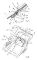
- eine perspektivische Ansicht des Kindersicherheitssitzes von hinten unten her in der Position der maximal hoch eingestellten Gurtführungsteil und Kopfstütze,
- Fig. 3a
- eine vergrößerte Ausschnittsdarstellung der Verriegelungseinrichtung in der in
Fig. 3 dargestellten Position, - Fig. 4
- eine Längsschnittdarstellung durch den Kindersicherheitssitz mit der maximal hoch eingestellten Kombination aus Gurtführungsteil und Kopfstütze,
- Fig. 4a
- eine Ausschnittsdarstellung der Verriegelungseinrichtung aus
Fig. 4 , - Fig. 5
- eine Draufsicht auf den Kindersicherheitssitz mit in maximal niedriger Position eingestellten Gurtführungsteil und Kopfstütze,
- Fig. 6
- eine perspektivische Ansicht von hinten unten auf den Kindersicherheitssitz in der Einstellung und Positionierung von Gurtführungsteil und Kopfstütze in maximal niedriger Position gemäß
Fig. 5 , - Fig. 6a
- eine Ausschnittsvergrößerung der Verriegelungseinrichtung aus
Fig. 6 , - Fig. 7
- eine Längsschnittdarstellung des Kindersicherheitssitzes in der Einstellung und Position von Gurtführungsteil und Kopfstütze gemäß
Fig. 5 , - Fig. 7a
- eine vergrößerte Ausschnittsdarstellung der Verriegelungseinrichtung aus
Fig. 7 , - Fig. 8
- eine perspektivische Ansicht von hinten unten des Kindersicherheitssitzes mit Gurtführungsteil und Kopfstütze in maximal hoher Position und mit durch Ziehen an dem Betätigungselement entriegelter Verriegelungseinrichtung,
- Fig. 8a
- eine vergrößerte Ausschnittsdarstellung der Verriegelungseinrichtung aus
Fig. 8 , - Fig. 9
- eine Längsschnittdarstellung des Kindersicherheitssitzes mit Gurtführungsteil und Kopfstützin maximal hoher Position und mit durch Ziehen an dem Betätigungselement in Entriegelungsstellung gebrachter Verriegelungseinrichtung und
- Fig. 9a
- eine Ausschnittsdarstellung der Verriegelungseinrichtung gemäß
Fig. 9 .
- Fig. 1
- a side view of an embodiment of a child safety seat according to the invention,
- Fig. 2
- a plan view of the child safety seat according to
Fig. 1 at maximum high set belt guide and headrest, - Fig. 3
- a perspective view of the child safety seat from the rear below in the position of the maximum high adjusted Gurtführungsteil and headrest,
- Fig. 3a
- an enlarged sectional view of the locking device in the in
Fig. 3 position shown, - Fig. 4
- a longitudinal sectional view through the child safety seat with the maximum set high combination of Gurtführungsteil and headrest,
- Fig. 4a
- a sectional view of the locking device
Fig. 4 . - Fig. 5
- a top view of the child safety seat with set in maximum low position Gurtführungsteil and headrest,
- Fig. 6
- a perspective view from the rear bottom of the child safety seat in the adjustment and positioning of Gurtführungsteil and headrest in maximum low position according to
Fig. 5 . - Fig. 6a
- an enlarged detail of the locking device
Fig. 6 . - Fig. 7
- a longitudinal sectional view of the child safety seat in the setting and position of Gurtführungsteil and headrest according to
Fig. 5 . - Fig. 7a
- an enlarged sectional view of the locking device
Fig. 7 . - Fig. 8
- a perspective view from the rear bottom of the child safety seat with Gurtführungsteil and headrest in the maximum high position and with unlocked by pulling on the actuator locking device,
- Fig. 8a
- an enlarged sectional view of the locking device
Fig. 8 . - Fig. 9
- a longitudinal sectional view of the child safety seat with Gurtführungsteil and headrestin a maximum high position and with by pulling on the actuator in unlocked position locking device and
- Fig. 9a
- a sectional view of the locking device according to
Fig. 9 ,
In den Figuren ist anhand eines Ausführungsbeispiels in Form eines Kindersicherheitssitzes 1, der für eine feste und sichere Anordnung und den Transport eines Kleinkindes in einem Fahrzeug ausgelegt ist und der Gruppe 0/0+ zugehört, eine mögliche Realisierung eines erfindungsgemäßen Kindersicherheitssitzes für Fahrzeuge in unterschiedlichsten Ansichten und mit verschiedenen Positionen der dem Kindersicherheitssitz 1 eigenen Gurteinrichtung sowie seiner Verriegelungseinrichtung dargestellt. Selbstverständlich kann die Erfindung auch in einem Kindersicherheitssitz einer anderen Klasse, bspw. der Gruppe 1, realisiert werden.In the figures, based on an embodiment in the form of a
Der Kindersicherheitssitz 1 gemäß dem Ausführungsbeispiel weist eine Sitzfläche 2 und eine sich an diese Sitzfläche 2 anschließende Rückenlehne 3 auf. Ein auf der Rückseite der Rückenlehne 3 angeordneter Gurthaken 4 sowie zwei seitlich angrenzend an die Sitzfläche 2 angeordnete Gurtaufnahmen 5 dienen in der üblichen und bekannten Weise der eingefädelten Aufnahme des Schultergurtabschnittes (in dem Gurthaken 4) sowie des Beckengurtabschnittes (durch die Gurtaufnahmen 5) eines im Fahrzeug befindlichen Dreipunktgurtes, um den Kindersicherheitssitz 1 so entgegen der Fahrtrichtung auf einem Fahrzeugsitz, z.B. auf dem Beifahrersitz oder einer Rückbank eines Fahrzeuges festzulegen.The
Der Kindersicherheitssitz 1 verfügt ferner über eine an diesem selbst ausgebildete und dort angeordnete Gurteinrichtung, die nach Art von Hosenträgergurten ausgebildete Schultergurte 6 (hier nur in einem Ausschnitt angedeutet) sowie eine im Bereich der Sitzfläche 2 angeordnete, hier nicht dargestellte Gurtschnalle enthält.The
In der Rückenlehne 3 sind zwei parallel und in Längsrichtung der Rückenlehne 3 verlaufende Längsschlitze 7 ausgebildet. Diese Längsschlitze 7 sind in einem starr mit der Sitzfläche 2 verbundenen Lehnenelement 8 gebildet. Auf der der Vorderseite der Rückenlehne 3, auf der ein in dem Kindersicherheitssitz 1 untergebrachtes Kind ruht, gegenüberliegenden Seite der Rückenlehne 3 ist ein Gurtführungsteil 9 angeordnet mit Gurtschlitzen 10, durch die die Schultergurte 6 von der Rückseite der Rückenlehne 3 her zu deren Vorderseite hin durchgeführt sind. An dem relativ zu dem Lehnenelement 8 in Längsrichtung der Rückenlehne 3 verschiebbar auf der Rückseite dieser Rückenlehne 3 angeordneten Gurtführungsteil 9 ist mit einer gelenkigen Anbindung eine Kopfstütze 11 angeordnet. Ein um eine Schwenkachse 12 verschwenkbarer Tragegriff 13 dient dem Erfassen und Transportieren des Kindersicherheitssitzes 1 in an sich bekannter Weise.In the
Auf der Rückseite der Rückenlehne 3 ist eine Verriegelungseinrichtung 14 ausgebildet, mittels derer das Gurtführungsteil 9 in unterschiedlichen möglichen Positionen relativ zu dem Lehnenteil 8 eingestellt und in Bezug zu letzterem in seiner Position fest verriegelt werden kann. Dabei umfasst das Gurtführungsteil 9 eine vollständig auf der Rückseite der Rückenlehne 3 angeordnete Deckplatte 15, welche die Längsschlitze 7 überdeckt.On the back of the
In den vergrößerten Darstellungen der
Die Verriegelungseinrichtung 14 weist zwei einander gegenüber liegende, in Längsrichtung der Rückenlehne 3 verlaufende, mit dem Lehnenelement 8 fest verbundene und jeweils auf gleicher Höhe einander gegenüber liegende Aufnahmekerben 16 aufweisende Aufnahmeleisten 17 auf. Sie umfasst ferner eine Riegelstange 18, die einen kreisrunden Durchmesser aufweist und mit ihren Enden jeweils in einer Aufnahmekerbe 16 der beiden Aufnahmeleisten 17 aufgenommen werden kann, um so gegen eine Längsbewegung zu verriegeln. Die Riegelstange 18 ist durch in mit der Abdeckplatte 15 des Gurtführungsteils 9 fest verbundenen Fortsätzen 19 ausgebildete Längsschlitze 20 hindurch geführt, wobei die Längsschlitze 20 und die Fortsätze 19 derart dimensioniert sind, dass die Riegelstange 18 in den Längsschlitzen 20 quer zur Ebene der Rückenlehne 3, insbesondere damit auch quer zur Abdeckplatte 15 soweit bewegt werden kann, dass sie vollständig aus den Aufnahmekerben 16 der Aufnahmeleisten 17 abgehoben ist und somit eine Relativverschiebung des Gurtführungsteils 9 gegenüber dem Lehnenteil 8 erlaubt.The locking
In einer mit hier nicht näher dargestellten Anschlägen zur Bewegungsbegrenzung versehenen, an der Abdeckplatte 15 des Gurtführungsteils 9 ausgebildeten und mit dieser fest verbundenen Führung 21 ist ein relativ zu dieser Führung 21 und damit dem Gurtführungsteil 9 in Längsrichtung der Rückenlehne 3 bewegbarer Kulissenschlitten 22 angeordnet.In a provided with not shown here stops for limiting movement, formed on the
Der Kulissenschlitten 22 weist in diesem Ausführungsbeispiel zwei Schenkel 22a auf, in denen jeweils ein Kulissenführungsschlitz 23 ausgebildet ist. Durch diese Kulissenführungsschlitze 23 verläuft die Riegelstange 18 hindurch, wobei die Kulissenführungsschlitze 23 einen Verlauf aufweisen, der jedenfalls in einem Abschnitt quer zu der Längserstreckung der Längsschlitze 19 sowie quer zu der Tangentialebene der Rückenlehne 3, mithin auch quer zu der Ebene der Abdeckplatte 15 verläuft. Insbesondere ist der Verlauf der Kulissenführungsschlitze 23 gekrümmt.The
Durch eine zwischen dem Kulissenschlitten 22 und einem fest mit der Abdeckplatte 15 verbundenen Widerlager 24 eingesetzte Schraubenfeder 25 wird der Kulissenschlitten 22 in eine maximal in Richtung der Sitzfläche 2 gelegene Position relativ zu der Abdeckplatte 15 und damit relativ zu dem Gurtführungsteil 9 gezwungen.By a between the
Die Schultergurte 6 verlaufen, wie durch eine nur ausschnittsweise gezeigte Darstellung erkennbar, auf der Rückseite der Rückenlehne 3 über die Riegelstange 18 hinweg und werden an dieser umgelenkt.The shoulder straps 6 extend, as can be seen by a representation only partially shown, on the back of the
An dem Kulissenschlitten 22 ist ein Zuggurt 26 festgelegt. Dieser Zuggurt 26 ist mit einem dem an dem Kulissenschlitten 22 festgelegten Ende gegenüber liegenden, freien Ende durch die Kopfstütze 11 gefädelt und ragt dort auf der Rückseite dieses Elementes hervor.On the
Durch Ziehen an dem Zuggurt 26 wird der Kulissenschlitten 22 entgegen der Federkraft der Schraubenfeder 25 relativ zu dem Gurtführungsteil 9, genauer zu der daran angeordneten und zu dem Gurtführungsteil gehörigen Abdeckplatte 15 in Richtung des oberen Endes der Rückenlehne 3 verschoben. Dadurch wird, gezwungen durch die in Richtung des unteren, zur Sitzfläche 2 hin gelegenen Endes des Kulissenschlittens 22 von der Rückseite der Rückenlehne 3 weg gerichtete, quer zur Ebene der Rückenlehne 3 verlaufende Führung des Kulissenführungsschlitzes 23 die Riegelstange 18 in den Längsschlitzen 20 nach außen zwangsgeführt und aus den Aufnahmekerben 16 der Aufnahmeleisten 17 heraus geführt. Nun kann das Gurtführungsteil 9 relativ zu dem Lehnenteil 8 in Längsrichtung der Lehne verschoben werden, bspw. aus einer in den
Aufgrund der Tatsache, dass auf der Vorderseite der Rückenlehne 3 die Kopfstütze 11 an dem Gurtführungsteil 9 in Längsrichtung der Rückenlehne 3 unverrückbar (lediglich in einer Richtung parallel zur Erstreckung der Riegelstange 18, also quer zur Längsrichtung der Rückenlehne 3 verschwenkbar) festgelegt ist, wird die Kopfstütze 11 bei der Einstellung der korrekten Lage des Gurtführungsteils 9 und damit des entsprechenden Abstandes der Gurtschlitze 10 und mithin der Austrittsposition der Schultergurte 6 zu der Sitzfläche 2 für eine entsprechende Anpassung an die Körpergröße des in dem Kindersicherheitssitz 1 aufzunehmenden Kindes mit justiert.Due to the fact that on the front of the
Der große Vorteil der erfindungsgemäßen Ausgestaltung besteht darin, dass auch bei in dem Fahrzeug installierten und festgelegten Kindersicherheitssitz 1 sowie in dem Kindersicherheitssitz 1 bereits eingesetztem Kind der Zuggurt 26 einfach ergriffen und mit diesem die Verriegelungseinrichtung 15 zur korrekten Justage der Position der Gurtschlitze 10 und damit des Abstandes des Durchtrittes der Schultergurte 6 durch die Rückenlehne 3 zur Sitzfläche 2 eingestellt werden kann und dies mit wenigen und einfach durchzuführenden Handgriffen. Soll der Abstand vergrößert werden, so kann zugleich mit dem Ziehen an dem Zuggurt 26 zum Entriegeln der Verriegelungsvorrichtung 15 auch eine in Richtung des oberen Endes der Rückenlehne 3 weisende Verschiebung des Gurtführungsteils 9 und der damit verbundenen Kopfstütze 11 vorgenommen werden, z.B. um diese aus der in den
In den
- 11
- KindersicherheitssitzChild safety seat
- 22
- Sitzflächeseat
- 33
- Rückenlehnebackrest
- 44
- GurthakenBelt hooks
- 55
- Gurtaufnahmebelt receiver
- 66
- Schultergurtshoulder
- 77
- Längsschlitzlongitudinal slot
- 88th
- Lehnenelementrest element
- 99
- GurtführungsteilGurtführungsteil
- 1010
- Gurtschlitzstrap slot
- 1111
- Kopfstützeheadrest
- 1212
- Schwenkachseswivel axis
- 1313
- Tragegriffhandle
- 1414
- Verriegelungseinrichtunglocking device
- 1515
- Abdeckplattecover
- 1616
- Aufnahmekerbereceiving notch
- 1717
- Aufnahmeleisterecording toolbar
- 1818
- Riegelstangelocking bar
- 1919
- Fortsatzextension
- 2020
- Längsschlitzlongitudinal slot
- 2121
- Führungguide
- 2222
- Kulissenschlittensetting slide
- 22a22a
- Schenkelleg
- 2323
- KulissenführungsschlitzLink guide slot
- 2424
- Widerlagerabutment
- 2525
- Schraubenfedercoil spring
- 2626
- ZuggurtTension Strap
Claims (12)
Priority Applications (3)
| Application Number | Priority Date | Filing Date | Title |
|---|---|---|---|
| EP12168981.4A EP2666664B1 (en) | 2012-05-22 | 2012-05-22 | Child safety seat for vehicles |
| CN2013101198566A CN103419688A (en) | 2012-05-22 | 2013-04-08 | Child safety seat for vehicles |
| US13/864,737 US8991919B2 (en) | 2012-05-22 | 2013-04-17 | Child safety seat for vehicles |
Applications Claiming Priority (1)
| Application Number | Priority Date | Filing Date | Title |
|---|---|---|---|
| EP12168981.4A EP2666664B1 (en) | 2012-05-22 | 2012-05-22 | Child safety seat for vehicles |
Publications (2)
| Publication Number | Publication Date |
|---|---|
| EP2666664A1 true EP2666664A1 (en) | 2013-11-27 |
| EP2666664B1 EP2666664B1 (en) | 2014-04-02 |
Family
ID=46149228
Family Applications (1)
| Application Number | Title | Priority Date | Filing Date |
|---|---|---|---|
| EP12168981.4A Active EP2666664B1 (en) | 2012-05-22 | 2012-05-22 | Child safety seat for vehicles |
Country Status (3)
| Country | Link |
|---|---|
| US (1) | US8991919B2 (en) |
| EP (1) | EP2666664B1 (en) |
| CN (1) | CN103419688A (en) |
Cited By (3)
| Publication number | Priority date | Publication date | Assignee | Title |
|---|---|---|---|---|
| CN105711450A (en) * | 2016-01-21 | 2016-06-29 | 宁波永驰婴童用品有限公司 | Headrest height adjusting mechanism of child safety seat |
| CN105946637A (en) * | 2016-04-15 | 2016-09-21 | 苏州纪宝儿童用品有限公司 | Child seat head support adjusting device |
| CN107856585A (en) * | 2016-09-16 | 2018-03-30 | 明门瑞士股份有限公司 | Child safety seat |
Families Citing this family (7)
| Publication number | Priority date | Publication date | Assignee | Title |
|---|---|---|---|---|
| US9327619B2 (en) * | 2013-03-08 | 2016-05-03 | Wonderland Nurserygood Company Limited | Child safety seat |
| US10435078B2 (en) | 2017-02-15 | 2019-10-08 | Nissan North America, Inc. | Airbox drain syphon tube valve |
| US10167967B2 (en) | 2017-02-15 | 2019-01-01 | Nissan North America, Inc. | Airbox drain valve |
| DE202018102435U1 (en) | 2018-05-02 | 2019-08-06 | Cybex Gmbh | Child seat for attachment to a motor vehicle seat |
| USD953757S1 (en) * | 2019-09-18 | 2022-06-07 | Cybex Gmbh | Child seat for motor car |
| CN110466399B (en) * | 2019-09-20 | 2024-03-08 | 安徽永驰婴童科技股份有限公司 | Child safety seat and rotary connection structure of base and seat body |
| CN114728606A (en) * | 2019-11-22 | 2022-07-08 | G·米特 | Child safety seat |
Citations (8)
| Publication number | Priority date | Publication date | Assignee | Title |
|---|---|---|---|---|
| EP0287259A2 (en) * | 1987-04-15 | 1988-10-19 | Britax-Excelsior Limited | Child's seat for a motor vehicle |
| US6030047A (en) | 1998-04-06 | 2000-02-29 | Cosco, Inc. | Child vehicle seat with child-restraint harness adjustment mechanism |
| US6491348B1 (en) | 2000-07-31 | 2002-12-10 | Cosco Management, Inc. | Child vehicle seat with child-restraint harness adjustment mechanism |
| US20030151282A1 (en) * | 2002-02-11 | 2003-08-14 | Bruce Williams | Child seat |
| EP1564065A2 (en) * | 2004-02-10 | 2005-08-17 | Takata Corporation | Child seat and shoulder adjuster |
| EP2208637A1 (en) | 2009-01-15 | 2010-07-21 | Dorel France Sa | Juvenile vehicle seat with headrest-height controller |
| EP2066526B1 (en) | 2006-09-21 | 2011-04-27 | Takata-Petri AG | Child's protection system |
| DE202011051484U1 (en) * | 2010-09-30 | 2012-01-31 | Ningbo Global Kids Baby Products Co., Ltd. | Device for adjusting headrest height for vehicle child safety seat |
Family Cites Families (21)
| Publication number | Priority date | Publication date | Assignee | Title |
|---|---|---|---|---|
| US4047755A (en) * | 1976-03-22 | 1977-09-13 | Quentin H. McDonald | Restraining means for an infant car seat |
| US4858997A (en) * | 1986-12-31 | 1989-08-22 | Shubin Steven A | Child safety car seat |
| GB2284012A (en) * | 1993-11-23 | 1995-05-24 | Wang Sheng Feng | A foldable baby chair |
| PT751033E (en) * | 1995-06-30 | 2001-06-29 | Margarete Schrader | CHILD SEAT FOR CARS |
| US6779843B2 (en) * | 2002-12-27 | 2004-08-24 | Cosco Management, Inc. | Harness-control panel adjuster for child-restraint seat |
| WO2006004896A2 (en) * | 2004-06-29 | 2006-01-12 | Kidnetik Corp. | Child restraint apparatus for a vehicle |
| US7625043B2 (en) * | 2005-09-15 | 2009-12-01 | Wonderland Nurserygoods Co., Ltd. | Child car seat with multiple use configurations |
| GB2444834B (en) * | 2006-12-12 | 2011-12-14 | Wonderland Nursery Goods | Head rest and harness adjustment for child car seat |
| US7547065B2 (en) * | 2007-02-23 | 2009-06-16 | Evenflo Company, Inc. | Child vehicle seat with harness adjustment mechanism |
| CN201176133Y (en) * | 2008-02-29 | 2009-01-07 | 林锡雷 | Child's safety seat for vehicle with headrest adjustable |
| CN201192996Y (en) * | 2008-04-10 | 2009-02-11 | 林锡雷 | Automobile children safety seat |
| CN102341268B (en) * | 2009-01-27 | 2014-03-12 | 葛莱儿婴儿产品股份有限公司 | Child safety seat with height adjust able harness and headrest |
| US8186757B2 (en) * | 2009-03-04 | 2012-05-29 | Cosco Management, Inc. | Child restraint system including a stationary seat support and a removable juvenile vehicle seat on the seat support |
| US8474907B2 (en) * | 2009-07-05 | 2013-07-02 | Graco Children's Products Inc. | Car seat installation and recline mechanism |
| CN201597477U (en) * | 2009-10-11 | 2010-10-06 | 林江娟 | Headrest adjusting mechanism of child safety seat for vehicle |
| CN201566523U (en) * | 2009-11-26 | 2010-09-01 | 宁波安普力儿童用品有限公司 | Children safety chair telescopic head resting mechanism for automobile |
| CN102811884B (en) * | 2010-03-24 | 2015-11-25 | 谛欧诺有限责任公司 | For children car seat being fastened to the coupling device of vehicle |
| CN201736846U (en) * | 2010-06-17 | 2011-02-09 | 宁波中哲汽车安全系统有限公司 | Child seat |
| JP5685509B2 (en) * | 2010-11-08 | 2015-03-18 | タカタ株式会社 | child seat |
| CN201941624U (en) * | 2011-03-02 | 2011-08-24 | 江苏幸运宝贝安全装置制造有限公司 | ISOFIX (international standards organization FIX) system for child safety seat of car |
| CN102390294B (en) * | 2011-10-17 | 2012-11-21 | 江苏幸运宝贝安全装置制造有限公司 | Full-azimuth, three-dimensional and adjustable children vehicle-mounted restraint system |
-
2012
- 2012-05-22 EP EP12168981.4A patent/EP2666664B1/en active Active
-
2013
- 2013-04-08 CN CN2013101198566A patent/CN103419688A/en active Pending
- 2013-04-17 US US13/864,737 patent/US8991919B2/en active Active
Patent Citations (8)
| Publication number | Priority date | Publication date | Assignee | Title |
|---|---|---|---|---|
| EP0287259A2 (en) * | 1987-04-15 | 1988-10-19 | Britax-Excelsior Limited | Child's seat for a motor vehicle |
| US6030047A (en) | 1998-04-06 | 2000-02-29 | Cosco, Inc. | Child vehicle seat with child-restraint harness adjustment mechanism |
| US6491348B1 (en) | 2000-07-31 | 2002-12-10 | Cosco Management, Inc. | Child vehicle seat with child-restraint harness adjustment mechanism |
| US20030151282A1 (en) * | 2002-02-11 | 2003-08-14 | Bruce Williams | Child seat |
| EP1564065A2 (en) * | 2004-02-10 | 2005-08-17 | Takata Corporation | Child seat and shoulder adjuster |
| EP2066526B1 (en) | 2006-09-21 | 2011-04-27 | Takata-Petri AG | Child's protection system |
| EP2208637A1 (en) | 2009-01-15 | 2010-07-21 | Dorel France Sa | Juvenile vehicle seat with headrest-height controller |
| DE202011051484U1 (en) * | 2010-09-30 | 2012-01-31 | Ningbo Global Kids Baby Products Co., Ltd. | Device for adjusting headrest height for vehicle child safety seat |
Cited By (4)
| Publication number | Priority date | Publication date | Assignee | Title |
|---|---|---|---|---|
| CN105711450A (en) * | 2016-01-21 | 2016-06-29 | 宁波永驰婴童用品有限公司 | Headrest height adjusting mechanism of child safety seat |
| CN105946637A (en) * | 2016-04-15 | 2016-09-21 | 苏州纪宝儿童用品有限公司 | Child seat head support adjusting device |
| CN107856585A (en) * | 2016-09-16 | 2018-03-30 | 明门瑞士股份有限公司 | Child safety seat |
| CN107856585B (en) * | 2016-09-16 | 2020-09-11 | 明门瑞士股份有限公司 | Child safety seat |
Also Published As
| Publication number | Publication date |
|---|---|
| US8991919B2 (en) | 2015-03-31 |
| US20130313874A1 (en) | 2013-11-28 |
| EP2666664B1 (en) | 2014-04-02 |
| CN103419688A (en) | 2013-12-04 |
Similar Documents
| Publication | Publication Date | Title |
|---|---|---|
| EP2666664B1 (en) | Child safety seat for vehicles | |
| EP2627533B1 (en) | Seat anchoring element for child safety seat or infant carrier | |
| EP2708407B1 (en) | Child seat, in particular for vehicles | |
| DE2802617A1 (en) | ANCHORING FOR BELT LOCKERS OF SAFETY BELTS ARRANGED IN VEHICLES | |
| DE202008005361U1 (en) | Device for fastening a child car seat to an anchoring web or bar of the body of a vehicle | |
| EP0191118B1 (en) | Child's safety device for vehicles | |
| DE19647448C2 (en) | Longitudinal adjustment device for seats, in particular motor vehicle seats | |
| DE202009013376U1 (en) | Car seat | |
| EP2139746B1 (en) | Stroller having a seat belt attachment and adjustment device | |
| DE102012220644A1 (en) | vehicle seat | |
| EP2161159B1 (en) | Safety device for a child seat in a vehicle | |
| DE102011008778A1 (en) | Belt lock feeder for vehicle, comprises drive unit, which is coupled with adjusting unit that moves belt lock between initial position and brought position | |
| DE3005818A1 (en) | Seat belt anchor point adjustment - has spring loaded block with stud engaging with optional hole in wall of C=section rail | |
| EP1452409A1 (en) | Seatbelt pretensioner with a height-adjustable belt guide | |
| DE102013010705B4 (en) | HEADREST, IN X-DIRECTION TO A SAFETY POSITION AND A COMPLETE POSITION | |
| DE102005050971A1 (en) | Crash-activated headrest for motor vehicle, has blocking part with opening for link from carrier structure, and release device which allows release of tension spring | |
| DE102014013080B4 (en) | Guide rail for a height adjuster | |
| DE202020100086U1 (en) | Child restraint system and associated adjustable headrest | |
| DE102009015202B3 (en) | Belt tongue for three-point-safety belt, is provided with tongue base body, C- shaped deflecting and clamping element with contact surface for three-point-safety belt | |
| DE2023957A1 (en) | ||
| DE1911872A1 (en) | Swivel seat belt buckle | |
| DE2419368B2 (en) | SAFETY DEVICE FOR THE OCCUPANTS OF VEHICLES, IN PARTICULAR OF MOTOR VEHICLES | |
| DE102005050223A1 (en) | Headrest for motor vehicle seat, has tension spring extending in direction between linear displacement path of support body and z-axis | |
| AT3133U1 (en) | SLIDE LADDER WITH CABLE AND LOCKING DEVICE | |
| EP1808092A1 (en) | Rucksack with two straps |
Legal Events
| Date | Code | Title | Description |
|---|---|---|---|
| PUAI | Public reference made under article 153(3) epc to a published international application that has entered the european phase |
Free format text: ORIGINAL CODE: 0009012 |
|
| 17P | Request for examination filed |
Effective date: 20121126 |
|
| AK | Designated contracting states |
Kind code of ref document: A1 Designated state(s): AL AT BE BG CH CY CZ DE DK EE ES FI FR GB GR HR HU IE IS IT LI LT LU LV MC MK MT NL NO PL PT RO RS SE SI SK SM TR |
|
| AX | Request for extension of the european patent |
Extension state: BA ME |
|
| GRAP | Despatch of communication of intention to grant a patent |
Free format text: ORIGINAL CODE: EPIDOSNIGR1 |
|
| INTG | Intention to grant announced |
Effective date: 20131218 |
|
| RBV | Designated contracting states (corrected) |
Designated state(s): AL AT BE BG CH CY CZ DE DK EE ES FI FR GB GR HR HU IE IS IT LI LT LU LV MC MK MT NL NO PL PT RO RS SE SI SK SM TR |
|
| GRAS | Grant fee paid |
Free format text: ORIGINAL CODE: EPIDOSNIGR3 |
|
| GRAA | (expected) grant |
Free format text: ORIGINAL CODE: 0009210 |
|
| AK | Designated contracting states |
Kind code of ref document: B1 Designated state(s): AL AT BE BG CH CY CZ DE DK EE ES FI FR GB GR HR HU IE IS IT LI LT LU LV MC MK MT NL NO PL PT RO RS SE SI SK SM TR |
|
| REG | Reference to a national code |
Ref country code: GB Ref legal event code: FG4D Free format text: NOT ENGLISH |
|
| REG | Reference to a national code |
Ref country code: CH Ref legal event code: EP Ref country code: AT Ref legal event code: REF Ref document number: 659871 Country of ref document: AT Kind code of ref document: T Effective date: 20140415 |
|
| REG | Reference to a national code |
Ref country code: IE Ref legal event code: FG4D Free format text: LANGUAGE OF EP DOCUMENT: GERMAN |
|
| REG | Reference to a national code |
Ref country code: DE Ref legal event code: R096 Ref document number: 502012000546 Country of ref document: DE Effective date: 20140515 |
|
| REG | Reference to a national code |
Ref country code: NL Ref legal event code: VDEP Effective date: 20140402 |
|
| PGFP | Annual fee paid to national office [announced via postgrant information from national office to epo] |
Ref country code: ES Payment date: 20140618 Year of fee payment: 3 |
|
| REG | Reference to a national code |
Ref country code: LT Ref legal event code: MG4D |
|
| PG25 | Lapsed in a contracting state [announced via postgrant information from national office to epo] |
Ref country code: NL Free format text: LAPSE BECAUSE OF FAILURE TO SUBMIT A TRANSLATION OF THE DESCRIPTION OR TO PAY THE FEE WITHIN THE PRESCRIBED TIME-LIMIT Effective date: 20140402 Ref country code: GR Free format text: LAPSE BECAUSE OF FAILURE TO SUBMIT A TRANSLATION OF THE DESCRIPTION OR TO PAY THE FEE WITHIN THE PRESCRIBED TIME-LIMIT Effective date: 20140703 Ref country code: FI Free format text: LAPSE BECAUSE OF FAILURE TO SUBMIT A TRANSLATION OF THE DESCRIPTION OR TO PAY THE FEE WITHIN THE PRESCRIBED TIME-LIMIT Effective date: 20140402 Ref country code: LT Free format text: LAPSE BECAUSE OF FAILURE TO SUBMIT A TRANSLATION OF THE DESCRIPTION OR TO PAY THE FEE WITHIN THE PRESCRIBED TIME-LIMIT Effective date: 20140402 Ref country code: BG Free format text: LAPSE BECAUSE OF FAILURE TO SUBMIT A TRANSLATION OF THE DESCRIPTION OR TO PAY THE FEE WITHIN THE PRESCRIBED TIME-LIMIT Effective date: 20140702 Ref country code: CY Free format text: LAPSE BECAUSE OF FAILURE TO SUBMIT A TRANSLATION OF THE DESCRIPTION OR TO PAY THE FEE WITHIN THE PRESCRIBED TIME-LIMIT Effective date: 20140402 Ref country code: IS Free format text: LAPSE BECAUSE OF FAILURE TO SUBMIT A TRANSLATION OF THE DESCRIPTION OR TO PAY THE FEE WITHIN THE PRESCRIBED TIME-LIMIT Effective date: 20140802 Ref country code: CZ Free format text: LAPSE BECAUSE OF FAILURE TO SUBMIT A TRANSLATION OF THE DESCRIPTION OR TO PAY THE FEE WITHIN THE PRESCRIBED TIME-LIMIT Effective date: 20140402 Ref country code: NO Free format text: LAPSE BECAUSE OF FAILURE TO SUBMIT A TRANSLATION OF THE DESCRIPTION OR TO PAY THE FEE WITHIN THE PRESCRIBED TIME-LIMIT Effective date: 20140702 |
|
| PG25 | Lapsed in a contracting state [announced via postgrant information from national office to epo] |
Ref country code: PL Free format text: LAPSE BECAUSE OF FAILURE TO SUBMIT A TRANSLATION OF THE DESCRIPTION OR TO PAY THE FEE WITHIN THE PRESCRIBED TIME-LIMIT Effective date: 20140402 Ref country code: LV Free format text: LAPSE BECAUSE OF FAILURE TO SUBMIT A TRANSLATION OF THE DESCRIPTION OR TO PAY THE FEE WITHIN THE PRESCRIBED TIME-LIMIT Effective date: 20140402 Ref country code: RS Free format text: LAPSE BECAUSE OF FAILURE TO SUBMIT A TRANSLATION OF THE DESCRIPTION OR TO PAY THE FEE WITHIN THE PRESCRIBED TIME-LIMIT Effective date: 20140402 Ref country code: SE Free format text: LAPSE BECAUSE OF FAILURE TO SUBMIT A TRANSLATION OF THE DESCRIPTION OR TO PAY THE FEE WITHIN THE PRESCRIBED TIME-LIMIT Effective date: 20140402 Ref country code: ES Free format text: LAPSE BECAUSE OF FAILURE TO SUBMIT A TRANSLATION OF THE DESCRIPTION OR TO PAY THE FEE WITHIN THE PRESCRIBED TIME-LIMIT Effective date: 20140402 Ref country code: HR Free format text: LAPSE BECAUSE OF FAILURE TO SUBMIT A TRANSLATION OF THE DESCRIPTION OR TO PAY THE FEE WITHIN THE PRESCRIBED TIME-LIMIT Effective date: 20140402 |
|
| PG25 | Lapsed in a contracting state [announced via postgrant information from national office to epo] |
Ref country code: PT Free format text: LAPSE BECAUSE OF FAILURE TO SUBMIT A TRANSLATION OF THE DESCRIPTION OR TO PAY THE FEE WITHIN THE PRESCRIBED TIME-LIMIT Effective date: 20140804 |
|
| REG | Reference to a national code |
Ref country code: DE Ref legal event code: R097 Ref document number: 502012000546 Country of ref document: DE |
|
| PG25 | Lapsed in a contracting state [announced via postgrant information from national office to epo] |
Ref country code: RO Free format text: LAPSE BECAUSE OF FAILURE TO SUBMIT A TRANSLATION OF THE DESCRIPTION OR TO PAY THE FEE WITHIN THE PRESCRIBED TIME-LIMIT Effective date: 20140402 Ref country code: MC Free format text: LAPSE BECAUSE OF FAILURE TO SUBMIT A TRANSLATION OF THE DESCRIPTION OR TO PAY THE FEE WITHIN THE PRESCRIBED TIME-LIMIT Effective date: 20140402 Ref country code: EE Free format text: LAPSE BECAUSE OF FAILURE TO SUBMIT A TRANSLATION OF THE DESCRIPTION OR TO PAY THE FEE WITHIN THE PRESCRIBED TIME-LIMIT Effective date: 20140402 Ref country code: DK Free format text: LAPSE BECAUSE OF FAILURE TO SUBMIT A TRANSLATION OF THE DESCRIPTION OR TO PAY THE FEE WITHIN THE PRESCRIBED TIME-LIMIT Effective date: 20140402 Ref country code: SK Free format text: LAPSE BECAUSE OF FAILURE TO SUBMIT A TRANSLATION OF THE DESCRIPTION OR TO PAY THE FEE WITHIN THE PRESCRIBED TIME-LIMIT Effective date: 20140402 |
|
| PLBE | No opposition filed within time limit |
Free format text: ORIGINAL CODE: 0009261 |
|
| STAA | Information on the status of an ep patent application or granted ep patent |
Free format text: STATUS: NO OPPOSITION FILED WITHIN TIME LIMIT |
|
| REG | Reference to a national code |
Ref country code: IE Ref legal event code: MM4A |
|
| 26N | No opposition filed |
Effective date: 20150106 |
|
| PG25 | Lapsed in a contracting state [announced via postgrant information from national office to epo] |
Ref country code: IT Free format text: LAPSE BECAUSE OF FAILURE TO SUBMIT A TRANSLATION OF THE DESCRIPTION OR TO PAY THE FEE WITHIN THE PRESCRIBED TIME-LIMIT Effective date: 20140402 |
|
| REG | Reference to a national code |
Ref country code: DE Ref legal event code: R097 Ref document number: 502012000546 Country of ref document: DE Effective date: 20150106 |
|
| PG25 | Lapsed in a contracting state [announced via postgrant information from national office to epo] |
Ref country code: IE Free format text: LAPSE BECAUSE OF NON-PAYMENT OF DUE FEES Effective date: 20140522 |
|
| PG25 | Lapsed in a contracting state [announced via postgrant information from national office to epo] |
Ref country code: RS Free format text: LAPSE BECAUSE OF FAILURE TO SUBMIT A TRANSLATION OF THE DESCRIPTION OR TO PAY THE FEE WITHIN THE PRESCRIBED TIME-LIMIT Effective date: 20141119 |
|
| PG25 | Lapsed in a contracting state [announced via postgrant information from national office to epo] |
Ref country code: SI Free format text: LAPSE BECAUSE OF FAILURE TO SUBMIT A TRANSLATION OF THE DESCRIPTION OR TO PAY THE FEE WITHIN THE PRESCRIBED TIME-LIMIT Effective date: 20140402 |
|
| PG25 | Lapsed in a contracting state [announced via postgrant information from national office to epo] |
Ref country code: MT Free format text: LAPSE BECAUSE OF FAILURE TO SUBMIT A TRANSLATION OF THE DESCRIPTION OR TO PAY THE FEE WITHIN THE PRESCRIBED TIME-LIMIT Effective date: 20140402 |
|
| PG25 | Lapsed in a contracting state [announced via postgrant information from national office to epo] |
Ref country code: SM Free format text: LAPSE BECAUSE OF FAILURE TO SUBMIT A TRANSLATION OF THE DESCRIPTION OR TO PAY THE FEE WITHIN THE PRESCRIBED TIME-LIMIT Effective date: 20140402 |
|
| REG | Reference to a national code |
Ref country code: FR Ref legal event code: PLFP Year of fee payment: 5 |
|
| PG25 | Lapsed in a contracting state [announced via postgrant information from national office to epo] |
Ref country code: HU Free format text: LAPSE BECAUSE OF FAILURE TO SUBMIT A TRANSLATION OF THE DESCRIPTION OR TO PAY THE FEE WITHIN THE PRESCRIBED TIME-LIMIT; INVALID AB INITIO Effective date: 20120522 Ref country code: LU Free format text: LAPSE BECAUSE OF NON-PAYMENT OF DUE FEES Effective date: 20140522 Ref country code: TR Free format text: LAPSE BECAUSE OF FAILURE TO SUBMIT A TRANSLATION OF THE DESCRIPTION OR TO PAY THE FEE WITHIN THE PRESCRIBED TIME-LIMIT Effective date: 20140402 Ref country code: BE Free format text: LAPSE BECAUSE OF FAILURE TO SUBMIT A TRANSLATION OF THE DESCRIPTION OR TO PAY THE FEE WITHIN THE PRESCRIBED TIME-LIMIT Effective date: 20140531 |
|
| REG | Reference to a national code |
Ref country code: FR Ref legal event code: PLFP Year of fee payment: 6 |
|
| REG | Reference to a national code |
Ref country code: FR Ref legal event code: PLFP Year of fee payment: 7 |
|
| PG25 | Lapsed in a contracting state [announced via postgrant information from national office to epo] |
Ref country code: MK Free format text: LAPSE BECAUSE OF FAILURE TO SUBMIT A TRANSLATION OF THE DESCRIPTION OR TO PAY THE FEE WITHIN THE PRESCRIBED TIME-LIMIT Effective date: 20140402 |
|
| PG25 | Lapsed in a contracting state [announced via postgrant information from national office to epo] |
Ref country code: AL Free format text: LAPSE BECAUSE OF FAILURE TO SUBMIT A TRANSLATION OF THE DESCRIPTION OR TO PAY THE FEE WITHIN THE PRESCRIBED TIME-LIMIT Effective date: 20140402 |
|
| PG25 | Lapsed in a contracting state [announced via postgrant information from national office to epo] |
Ref country code: ES Free format text: THE PATENT HAS BEEN ANNULLED BY A DECISION OF A NATIONAL AUTHORITY Effective date: 20140402 |
|
| PGFP | Annual fee paid to national office [announced via postgrant information from national office to epo] |
Ref country code: FR Payment date: 20230517 Year of fee payment: 12 Ref country code: DE Payment date: 20230424 Year of fee payment: 12 Ref country code: CH Payment date: 20230605 Year of fee payment: 12 |
|
| PGFP | Annual fee paid to national office [announced via postgrant information from national office to epo] |
Ref country code: AT Payment date: 20230516 Year of fee payment: 12 |
|
| PGFP | Annual fee paid to national office [announced via postgrant information from national office to epo] |
Ref country code: GB Payment date: 20230522 Year of fee payment: 12 |