EP2665294A2 - Support of a multichannel audio extension - Google Patents
Support of a multichannel audio extension Download PDFInfo
- Publication number
- EP2665294A2 EP2665294A2 EP13165116.8A EP13165116A EP2665294A2 EP 2665294 A2 EP2665294 A2 EP 2665294A2 EP 13165116 A EP13165116 A EP 13165116A EP 2665294 A2 EP2665294 A2 EP 2665294A2
- Authority
- EP
- European Patent Office
- Prior art keywords
- spectral
- mdct
- channel signal
- frequency band
- channel
- Prior art date
- Legal status (The legal status is an assumption and is not a legal conclusion. Google has not performed a legal analysis and makes no representation as to the accuracy of the status listed.)
- Withdrawn
Links
Images


Classifications
-
- H—ELECTRICITY
- H04—ELECTRIC COMMUNICATION TECHNIQUE
- H04S—STEREOPHONIC SYSTEMS
- H04S3/00—Systems employing more than two channels, e.g. quadraphonic
-
- G—PHYSICS
- G10—MUSICAL INSTRUMENTS; ACOUSTICS
- G10L—SPEECH ANALYSIS OR SYNTHESIS; SPEECH RECOGNITION; SPEECH OR VOICE PROCESSING; SPEECH OR AUDIO CODING OR DECODING
- G10L19/00—Speech or audio signals analysis-synthesis techniques for redundancy reduction, e.g. in vocoders; Coding or decoding of speech or audio signals, using source filter models or psychoacoustic analysis
- G10L19/008—Multichannel audio signal coding or decoding using interchannel correlation to reduce redundancy, e.g. joint-stereo, intensity-coding or matrixing
-
- H—ELECTRICITY
- H04—ELECTRIC COMMUNICATION TECHNIQUE
- H04S—STEREOPHONIC SYSTEMS
- H04S1/00—Two-channel systems
- H04S1/007—Two-channel systems in which the audio signals are in digital form
Landscapes
- Engineering & Computer Science (AREA)
- Physics & Mathematics (AREA)
- Acoustics & Sound (AREA)
- Signal Processing (AREA)
- Multimedia (AREA)
- Mathematical Physics (AREA)
- Computational Linguistics (AREA)
- Health & Medical Sciences (AREA)
- Audiology, Speech & Language Pathology (AREA)
- Human Computer Interaction (AREA)
- Compression, Expansion, Code Conversion, And Decoders (AREA)
Abstract
Description
- The invention relates to multichannel audio coding and to multichannel audio extension in multichannel audio coding. More specifically, the invention relates to a method for supporting a multichannel audio extension at an encoding end of a multichannel audio coding system, to a method for supporting a multichannel audio extension at a decoding end of a multichannel audio coding system, to pa multichannel audio encoder and a multichannel extension encoder for a multichannel audio encoder, to a multichannel audio decoder and a multichannel extension decoder for a multichannel audio decoder, and finally, to a multichannel audio coding system.
- Audio coding systems are known from the state of the art. They are used in particular for transmitting or storing audio signals.
-
Figure 1 shows the basic structure of an audio coding system, which is employed for transmission of audio signals. The audio coding system comprises anencoder 10 at a transmitting side and adecoder 11 at a receiving side. An audio signal that is to be transmitted is provided to theencoder 10. The encoder is responsible for adapting the incoming audio data rate to a bitrate level at which the bandwidth conditions in the transmission channel are not violated. Ideally, theencoder 10 discards only irrelevant information from the audio signal in this encoding process. The encoded audio signal is then transmitted by the transmitting side of the audio coding system and received at the receiving side of the audio coding system. Thedecoder 11 at the receiving side reverses the encoding process to obtain a decoded audio signal with little or no audible degradation. - Alternatively, the audio coding system of
figure 1 could be employed for archiving audio data. In that case, the encoded audio data provided by theencoder 10 is stored in some storage unit, and thedecoder 11 decodes audio data retrieved from this storage unit. In this alternative, it is the target that the encoder achieves a bitrate which is as low as possible, in order to save storage space. - The original audio signal which is to be processed can be a mono audio signal or a multichannel audio signal containing at least a first and a second channel signal. An example of a multichannel audio signal is a stereo audio signal, which is composed of a left channel signal and a right channel signal.
- Depending on the allowed bitrate, different encoding schemes can be applied to a stereo audio signal. The left and right channel signals can be encoded for instance independently from each other. But typically, a correlation exists between the left and the right channel signals, and the most advanced coding schemes exploit this correlation to achieve a further reduction in the bitrate.
- Particularly suited for reducing the bitrate are low bitrate stereo extension methods. In a stereo extension method, the stereo audio signal is encoded as a high bitrate mono signal, which is provided by the encoder together with some side information reserved for a stereo extension. In the decoder, the stereo audio signal is then reconstructed from the high bitrate mono signal in a stereo extension making use of the side information. The side information typically takes only a few kbps of the total bitrate.
- If a stereo extension scheme aims at operating at low bitrates, an exact replica of the original stereo audio signal cannot be obtained in the decoding process. For the thus required approximation of the original stereo audio signal, an efficient coding model is necessary.
- The most commonly used stereo audio coding schemes are Mid Side (MS) stereo and Intensity Stereo (IS).
- In MS stereo, the left and right channel signals are transformed into sum and difference signals, as described for example by J. D. Johnston and A. J . Ferreira in "Sum-difference stereo transform coding", ICASSP-92 Conference Record, 1992, pp. 569-572. For a maximum coding efficiency, this transformation is done in both, a frequency and a time dependent manner. MS stereo is especially useful for high quality, high bitrate stereophonic coding.
- In the attempt to achieve lower bitrates, IS has been used in combination with this MS coding, where IS constitutes a stereo extension scheme. In IS coding, a portion of the spectrum is coded only in mono mode, and the stereo audio signal is reconstructed by providing in addition different scaling factors for the left and right channels, as described for instance in documents
US 5,539,829 andUS 5,606,618 . - Two further, very low bitrate stereo extension schemes have been proposed with Binaural Cue Coding (BCC) and Bandwidth Extension (BWE). In BCC, described by F. Baumgarte and C. Faller in "Why Binaural Cue Coding is Better than Intensity Stereo Coding, AES 112th Convention, May 10-13, 2002, Preprint 5575, the whole spectrum is coded with IS. In BWE coding, described in ISO/IEC JTC1/SC29/WG11 (MPEG-4), "Text of ISO/IEC 14496-3:2001/FPDAM 1, Bandwidth Extension", N5203 (output document from MPEG 62nd meeting), October 2002, a bandwidth extension is used to extend the mono signal to a stereo signal.
- Moreover, document
US 6,016,473 proposes a low bit-rate spatial coding system for coding a plurality of audio streams representing a soundfield. On the encoder side, the audio streams are divided into a plurality of subband signals, representing a respective frequency subband. Then, a composite signals representing the combination of these subband signals is generated. In addition, a steering control signal is generated, which indicates the principal direction of the soundfield in the subbands, e.g. in form of weighted vectors. On the decoder side, an audio stream in up to two channels is generated based on the composite signal and the associated steering control signal. - It is an object of the invention to support the extension of a mono audio signal to a multichannel audio signal based on side information in an efficient way.
- For the encoding end of a multichannel audio coding system, a first method for supporting a multichannel audio extension is proposed, which comprises transforming a first channel signal of a multichannel audio signal into the frequency domain, resulting in a spectral first channel signal and transforming a second channel signal of this multichannel audio signal into the frequency domain, resulting in a spectral second channel signal. The proposed method further comprises determining for each of a plurality of adjacent frequency bands whether the spectral first channel signal, the spectral second channel signal or none of the spectral channel signals is dominant in the respective frequency band, and providing a corresponding state information for each of the frequency bands.
- In addition, a multichannel audio encoder and an extension encoder for a multichannel audio encoder are proposed, which comprise means for realizing the first proposed method.
- For the decoding end of a multichannel audio coding system, a second method for supporting a multichannel audio extension is proposed, which comprises transforming a received mono audio signal into the frequency domain, resulting in a spectral mono audio signal. The proposed second method further comprises generating a spectral first channel signal and a spectral second channel signal out of the spectral mono audio signal by weighting the spectral mono audio signal separately in each of a plurality of adjacent frequency bands for each of the spectral first channel signal and the spectral second channel signal based on at least one gain value and in accordance with a received state information. The state information indicates for each of the frequency bands whether the spectral first channel signal, the spectral second channel signal or none of these spectral channel signals is to be dominant within the respective frequency band.
- In addition, a multichannel audio decoder and an extension decoder for a multichannel audio decoder are proposed, which comprise means for realizing the second proposed method.
- Finally, a multichannel audio coding system is proposed, which comprises as well the proposed multichannel audio encoder as the proposed multichannel audio decoder.
- The invention proceeds from the consideration that a stereo extension on a frequency band basis is particularly efficient. The invention proceeds further from the idea that a state information indicating which channel signal is dominant in each frequency band, if any, are particularly suited as side information for extending a mono audio signal to a multichannel audio signal. The state information can be evaluated at a receiving end under consideration of a gain information representing a specific degree of the dominance of channel signals for reconstructing the original stereo signal.
- The invention provides an alternative to the known solutions.
- It is an advantage of the invention that it supports an efficient multichannel audio coding, which requires at the same time a relatively low computational complexity compared to known multichannel extension solutions.
- Also compared to the solution of document
US 6,016,473 , which is targeted more towards surround coding than stereo or other multichannel audio coding, lower bitrates and less required computations can be expected. - Preferred embodiments of the invention become apparent from the dependent claims.
- In a preferred embodiment, at least one gain value representative of the degree of this dominance is calculated and provided by the encoding end, in case it was determined that one of the spectral first channel signal and the spectral second channel signal is dominant in at least one of the frequency bands. Alternatively, at least one gain value could be predetermined and stored at the receiving end.
- In the decision which state information should be assigned to a certain frequency band, a binaural psychoacoustical model is suited to provide a useful assistance. Since psychoacoustical models typically require relatively high computational resources, they may take effect in particular in devices in which the computational resources are not very limited.
- The spectral first channel signal and the spectral second channel signal generated at the decoding end have to be transformed into the time domain, before they can be presented to a user.
- In a first advantageous embodiment, the generated spectral first and second channel signals are transformed at the decoding end directly into the time domain, resulting in a first channel signal and a second channel signal of a reconstructed multichannel audio signal.
- Such an embodiment, however, will usually operate at rather low bitrates, e.g. at less than 4 kbps, and for applications in which a higher stereo extension bitrate is available, this embodiment does not scale in quality.
- With a second advantageous embodiment, an improved stereo extension can be achieved that is suited to scale both in quality and bitrate. In the second advantageous embodiment, an additional enhancement information is generated on the encoding end, and this additional enhancement information is used at the decoding end in addition for reconstructing the original multichannel audio signal based on the generated spectral first and second channel signals.
- For generating the enhancement information at the encoding end, the spectral first channel signal and the spectral second channel signal are reconstructed not only at the decoding end but also at the encoding end based on the state information. The enhancement information is then generated such that it reflects for each spectral sample of those frequency bands, for which the state information indicates that one of the channel signals is dominant, sample-by-sample the difference between the reconstructed spectral first and second channel signals on the one hand and original spectral first and second channel signals on the other hand. It is to be noted that the reflected difference for some of the samples may also consist in an indication that the difference is so minor that it is not considered.
- The second advantageous embodiment improves the first advantageous embodiment with only moderate additional complexity and provides a wider operating coverage of the invention. It is an advantage particularly of the second advantageous embodiment that it utilizes already created stereo extension information to obtain a more accurate approximation of the original stereo audio image, without generating extra side information. It is further an advantage particularly of the second advantageous embodiment that it enables a scalability in the sense that the decoding end can decide depending on its resources, e.g. on its memory or on its processing capacities, whether to decode only the base stereo extension bitstream or in addition the enhancement information. In order to enable the encoding end to adjust the amount of the additional enhancement information to the available bitrate, the encoding end preferably provides an information on the bitrate employed for the stereo extension information, i.e. at least the state information, and the additional enhancement information.
- The enhancement information can be processed at the encoding end and the decoding end either as well in the extension encoder and decoder, respectively, or in a dedicated additional component.
- The multichannel audio signal can be in particular a stereo audio signal having a left channel signal and a right channel signal. In case of more channels, the proposed coding is performed to channel pairs.
- The multichannel audio extension enabled by the invention performs best at mid and high frequencies, at which spatial hearing relies mostly on amplitude level differences. For low frequencies, preferably a fine-tuning is realized in addition. Especially the dynamic range of the level modification gain may be limited in this fine-tuning.
- The required transformations from the time domain into the frequency domain and from the frequency domain into the time domain can be achieved with different types of transforms, for example with a Modified Discrete Cosine Transform (MDCT) and an Inverse MDCT (IMDCT), with a Fast Fourier Transform (FFT) and an Inverse FFT (IFFT) or with a Discrete Cosine Transform (DCT) and an Inverse DCT (IDCT).
- The invention can be used with various codecs, in particular, though not exclusively, with Adaptive Multi-Rate Wideband extension (AMR-WB+), which is suited for high audio quality.
- The invention can further be implemented either in software or using a dedicated hardware solution. Since the enabled multichannel audio extension is part of a coding system, it is preferably implemented in the same way as the overall coding system.
- The invention can be employed in particular for storage purposes and for transmissions, e.g. to and from mobile terminals.
- Other objects and features of the present invention will become apparent from the following detailed description of exemplary embodiments of the invention considered in conjunction with the accompanying drawings.
- Fig. 1
- is a block diagram presenting the general structure of an audio coding system;
- Fig. 2
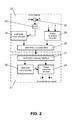
- is a high level block diagram of a stereo audio coding system in which a first embodiment of the invention can be implemented;
- Fig. 3
- illustrates the processing on a transmitting side of the stereo audio coding system of
figure 2 in the first embodiment of the invention; - Fig. 4
- illustrates the processing on a receiving side of the stereo audio coding system of
figure 2 in the first embodiment of the invention; - Fig. 5
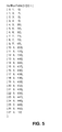
- is an exemplary Huffman table employed in a first possible supplementation of the first embodiment of the invention;
- Fig. 6
- is a flow chart illustrating a second possible supplementation of the embodiment of the first invention;
- Fig. 7
- is a high level block diagram of a stereo audio coding system in which a second embodiment of the invention can be implemented;
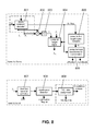
- Fig. 8
- illustrates the processing on a transmitting side of the stereo audio coding system of
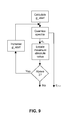
figure 7 in the second embodiment of the invention; - Fig. 9
- is a flow chart illustrating a quantization loop used in the processing of
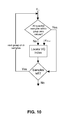
figure 8 ; - Fig. 10
- is a flow chart illustrating a codebook index assignment loop used in the processing of
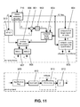
figure 8 ; and - Fig. 11
- illustrates the processing on a receiving side of the stereo audio coding system of
figure 7 in the second embodiment of the invention. -
Figure 1 has already been described above. - A first embodiment of the invention will now be described with reference to
figures 2 to 6 . -
Figure 2 presents the general structure of a stereo audio coding system, in which the invention can be implemented. The stereo audio coding system can be employed for transmitting a stereo audio signal which is composed of a left channel signal and a right channel signal. - The stereo audio coding system of
figure 2 comprises astereo encoder 20 and astereo decoder 21. Thestereo encoder 20 encodes stereo audio signals and transmits them to thestereo decoder 21, while thestereo decoder 21 receives the encoded signals, decodes them and makes them available again as stereo audio signals. Alternatively, the encoded stereo audio signals could also be provided by thestereo encoder 20 for storage in a storing unit, from which they can be extracted again by thestereo decoder 21. - The
stereo encoder 20 comprises a summingpoint 22, which is connected via ascaling unit 23 to an AMR-WB+mono encoder component 24. The AMR-WB+mono encoder component 24 is further connected to an AMR-WB+ bitstream multiplexer (MUX) 25. In addition, thestereo encoder 20 comprises astereo extension encoder 26, which is equally connected to the AMR-WB+ bitstream multiplexer 25. - The
stereo decoder 21 comprises an AMR-WB+ bitstream demultiplexer (DEMUX) 27, which is connected on the one hand to an AMR-WB+mono decoder component 28 and on the other hand to astereo extension decoder 29. The AMR-WB+mono decoder component 28 is further connected to thestereo extension decoder 29. - When a stereo audio signal is to be transmitted, the left channel signal L and the right channel signal R of the stereo audio signal are provided to the
stereo encoder 20. The left channel signal L and the right channel signal R are assumed to be arranged in frames. - The left and right channel signals L, R are summed by the summing
point 22 and scaled by a factor 0.5 in thescaling unit 23 to form a mono audio signal M. The AMR-WB+mono encoder component 24 is then responsible for encoding the mono audio signal in a known manner to obtain a mono signal bitstream. - The left and right channel signals L, R provided to the
stereo encoder 20 are processed in addition in thestereo extension encoder 26, in order to obtain a bitstream containing side information for a stereo extension. - The bitstreams provided by the AMR-WB+
mono encoder component 24 and thestereo extension encoder 26 are multiplexed by the AMR-WB+ bitstream multiplexer 25 for transmission. - The transmitted multiplexed bitstream is received by the
stereo decoder 21 and demultiplexed by the AMR-WB+ bitstream demultiplexer 27 into a mono signal bitstream and a side information bitstream again. The mono signal bitstream is forwarded to the AMR-WB+mono decoder component 28 and the side information bitstream is forwarded to thestereo extension decoder 29. - The mono signal bitstream is then decoded in the AMR-WB+
mono decoder component 28 in a known manner. The resulting mono audio signal M is provided to thestereo extension decoder 29. Thestereo extension decoder 29 decodes the bitstream containing the side information for the stereo extension and extends the received mono audio signal M based on the obtained side information into a left channel signal L and a right channel signal R. The left and right channel signals L, R are then output by thestereo decoder 21 as reconstructed stereo audio signal. - The
stereo extension encoder 26 and thestereo extension decoder 29 are designed according to an embodiment of the invention, as will be explained in the following. - The processing in the
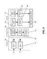
stereo extension encoder 26 is illustrated in more detail infigure 3 . - The processing in the
stereo extension encoder 26 comprises three stages. In a first stage, which is illustrated on the left hand side offigure 3 , signals are processed per frame. In a second stage, which is illustrated in the middle offigure 3 , signals are processed per frequency band. In a third stage, which is illustrated on the right hand side offigure 3 , signals are processed again per frame. In each stage, various processing portions 30-38 are indicated. - In the first stage, a received left channel signal L is transformed by an
MDCT portion 30 by means of a frame based MDCT into the frequency domain, resulting in a spectral channel signal LMDCT. In parallel, a received right channel signal R is transformed by anMDCT portion 31 by means of a frame based MDCT into the frequency domain, resulting in a spectral channel signal RMDCT. The MDCT has been described in detail e.g. by J.P. Princen, A.B. Bradley in "Analysis/synthesis filter bank design based on time domain aliasing cancellation", IEEE Trans. Acoustics, Speech, and Signal Processing, 1986, Vol. ASSP-34, No. 5, Oct. 1986, pp. 1153-1161, and by S. Shlien in "The modulated lapped transform, its time-varying forms, and its applications to audio coding standards", IEEE Trans. Speech, and Audio Processing, Vol. 5, No. 4, Jul. 1997, pp. 359-366. - In the second stage, the spectral channel signals LMDCT and RMDCT are processed within the current frame in several adjacent frequency bands. The frequency bands follow the boundaries of critical bands, as explained in detail by E. Zwicker, H. Fastl in "Psychoacoustics, Facts and Models", Springer-Verlag, 1990. For example, for coding of mid frequencies from 750 Hz to 6 kHz at a sample rate of 24kHz, the widths IS_ WidthLenBuf[] in samples of the frequency bands for a total number of frequency bands numTotalBands of 27 are as follows:
- IS_WidthLenBuf[] = {3, 3, 3, 3, 3, 3, 3, 4, 4, 5, 5, 5, 6, 6, 7, 7, 8, 9, 9, 10, 11, 14, 14, 15, 15, 17, 18}.
- First, a
processing portion 32 computes channel weights for each frequency band for the spectral channel signals LMDCT and RMDCT, in order to determine the respective influence of the left and right channel signals L and R in the original stereo audio signal in each frequency band. - The two channels weights for each frequency band are computed according to the following equations:

with

where fband is a number associated to the respectively considered frequency band, and where n is the offset in spectral samples to the start of this frequency band fband. That is, the intermediate values EL and ER represent the sum of the squared level of each spectral sample in a respective frequency band and a respective spectral channel signal. - In a
subsequent processing portion 33, to each frequency band one of the states LEFT, RIGHT and CENTER is assigned. The LEFT state indicates a dominance of the left channel signal in the respective frequency band, the RIGHT state indicates a dominance of the right channel signal in the respective frequency band, and the CENTER state represents mono audio signals in the respective frequency band. The assigned states are represented by a respective state flag IS_flag(fband) which is generated for each frequency band. - The state flags are generated more specifically based on the following equation:

with


- The parameter threshold in equation (2) determines how good the reconstruction of the stereo image should be. In the current embodiment, the value of the parameter threshold is set to 1.5. Thus, if the weight of one of the spectral channels does not exceed the weight of the respective other one of the spectral channels by at least 50%, the state flag represents the CENTER state.
- In case the state flag represents a LEFT state or a RIGHT state, in addition level modification gains are calculated in a
subsequent processing portion 34. The level modification gains allow a reconstruction of the stereo audio signal within the frequency bands when proceeding from the mono audio signal M. - The level modification gain gLR(fband) is calculated for each frequency band fband according to the equation:

- In the third stage, the generated level modification gains gLR(fband) and the generated stage flags IS_flag(fband) are further processed on a frame basis for transmission.
- The level modification gains can be transmitted for each frequency band or only once per frame. If only a common gain value is to be transmitted for all frequency bands, the common level modification gain gLR_average is calculated in processing
portion 35 for each frame according to the equation: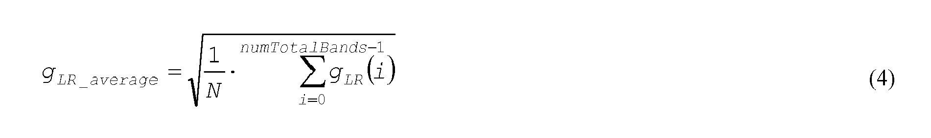

- Thus, the common level modification gain gLR_average constitutes the average of all frequency band associated level modification gains gLR(fband) which are no equal to zero.
- Processing
portion 36 then quantizes the common level modification gain gLR_average or the dedicated level modification gains gLR(fband) using scalar or, preferably, vector quantization techniques. The quantized gain or gains are coded into a bit sequence and provided as a first part of a side information bitstream to the AMR-WB+ bitstream multiplexer 25 of thestereo encoder 20 offigure 2 . In the presented embodiment, the gain is coded using 5 bits, but this value can be changed depending on how coarsely the gain(s) is (are) to be quantized. - For coding the state flags for transmission, a coding scheme is selected in processing
portion 37 for each frame, in order to minimize the bit consumption with a maximum efficiency. - More specifically, three coding schemes are defined for selection. The coding scheme indicates which state appears most frequently within the frame and is selected according to the following equation:


- Thus, a CENTER coding scheme is selected in case the CENTER state appears most frequently within a frame, a LEFT coding scheme is selected in case the LEFT state appears most frequently within a frame, and a RIGHT coding scheme is selected in case the RIGHT state appears most frequently within a frame. The selected coding scheme itself is coded by two bits.
- Processing
portion 37 codes the state flags according the coding scheme selected in processingportion 36. - In each of the coding schemes, the state which appears most frequently is coded in a respective first bit, while the remaining two states are coded in an eventual second bit.
- In case the CENTER coding scheme was selected and in case the CENTER state was also assigned to a specific frequency band, a '1' is provided as first bit for this specific frequency band, otherwise a '0' is provided as first bit. In the latter case, a '0' is provided as second bit, if the LEFT state was assigned to this specific frequency band, and a '1' is provided as second bit, if the RIGHT state was assigned to this specific frequency band.
- In case the LEFT coding scheme was selected and in case the LEFT state was also assigned to a specific frequency band, a '1' is provided as first bit for this specific frequency band, otherwise, a '0' is provided as first bit. In the latter case, a '0' is provided as second bit, if the RIGHT state was assigned to this specific frequency band, and a '1' is provided as second bit, if the CENTER state was assigned to this specific frequency band.
- Finally, in case the RIGHT coding scheme was selected and in case the RIGHT state was also assigned to a specific frequency band, a '1' is provided as first bit for this specific frequency band, otherwise, a '0' is provided as first bit. In the latter case, a '0' is provided as second bit, if the CENTER state was assigned to this specific frequency band, and a '1' is provided as second bit, if the LEFT state was assigned to this specific frequency band.
- The 2-bit indication of the coding scheme and the coded state flags for all frequency bands are provided as a second part of a side information bitstream to the AMR-
WB+ bitstream multiplexer 25 of thestereo encoder 20 offigure 2 . - The AMR-
WB+ bitstream multiplexer 25 multiplexes the received side information bitstream with the mono signal bitstream for transmission, as described above with reference tofigure 2 . - The transmitted signal is received by the
stereo decoder 21 offigure 2 and processed by the AMR-WB+ bitstream demultiplexer 27 and the AMR-WB+mono decoder component 28 as decribed above. - The processing in the
stereo extension decoder 29 of thestereo decoder 21 offigure 2 is illustrated in more detail infigure 4. Figure 4 is a schematic block diagram of thestereo extension decoder 29. - The
stereo extension decoder 29 comprises a delayingportion 40, which is connected via anMDCT portion 41 to aweighting portion 42. Thestereo extension decoder 29 further comprises again extraction portion 43 and anIS_flag extraction portion 44, an output of both being connected to an input of theweighting portion 42. Theweighting portion 42 has two outputs, each one connected to the input of anotherIMDCT portion - A mono audio signal M output by the AMR-WB+
mono decoder component 28 of thestereo decoder 21 offigure 2 is first fed to the delayingportion 40, since the mono audio signal M may have to be delayed if the decoded mono audio signal is not time-aligned with the encoder input signal. - Then, the mono audio signal is transformed by the
MDCT portion 41 into the frequency domain by means of a frame based MDCT. The resulting spectral mono audio signal MMDCT is fed to theweighting portion 42. - At the same time, the AMR-
WB+ bitstream demultiplexer 27 offigure 2 , which is also indicated infigure 4 , provides the first portion of the side information bitstream to thegain extraction portion 43 and the second portion of the side information bitstream to theIS_flag extraction portion 44. - The
gain extraction portion 43 extracts for each frame the common level modification gain or the dedicated level modification gains from the first part of the side information bitstream, and decodes the extracted gain or gains. The decoded gain gLR_average is or the decoded gains gLR(fband) are provided to theweighting portion 42. - The
IS_flag extraction portion 44 extracts and decodes for each frame the indication of the coding scheme and the state flags IS_flag(fband) from the second part of the side information bitstream. - Decoding of the state flags is performed such that for each frequency band, first only one bit is read. In case this bit is equal to '1', the state represented by the indicated coding scheme is assigned to the respective frequency band. In case the first bit is equal to '0', a second bit is read and the correct state is assigned to the respective frequency band depending on this second bit.
- If the CENTER coding scheme is indicated, the state flags are set as follows depending on the last read bit:

- If the LEFT coding scheme is indicated, the state flags are set as follows depending on the last read bit:

- And finally, if RIGHT coding scheme is indicated, the state flags are set as follows depending on the last read bit:

- In the above equations (6) to (8), the function BsGetBits(x) reads x bits from an input bitstream buffer.
- For each frequency band, the resulting state flag IS_flag(fband) is provided to the
weighting portion 42. - Based on the received level modification gain or gains and the received state flags, the spectral mono audio signal MMDCT is extended in the
weighting portion 42 to spectral left and right channel signals. - The spectral left and right channel signals are obtained from the spectral mono audio signal MMDCT according to the following equations:


- Equations (9) and (10) operate on a frequency band basis. For each frequency band associated to the number fband, a respective state flag IS_flag indicates to the
weighting portion 42 whether the spectral mono audio signal samples MMDCT(n) within the frequency band originate mainly from the original left or the original right channel signal. The level modification gain gLR(fband) represents the degree of the dominance of the left or the right channel signal in the original stereo audio signal, if any, and is used for reconstructing the stereo image within each frequency band. To this end, the level modification gain is multiplied to the spectral mono audio signal samples for obtaining samples for the dominant channel signal and the reciprocal value of the level modification gain is multiplied to the spectral mono audio signal samples for obtaining samples for the respective other channel. It is to be noted that this reciprocal value may also be weighted by a fixed or a variable value. The reciprocal value in equations (9) and (10) it may be substituted for instance by
- The entire spectral left channel signal within a specific frequency band is composed of all sample values LMDCT(n) determined for this specific frequency band. Equally, the entire spectral right channel signal within a specific frequency band is composed of all sample values RMDCT(n) determined for this specific frequency band.
- In case a common level modification gain is used, the gain gLR(fband) in equations (9) and (10) is the equal to this common value gLR_average for all frequency bands.
- If multiple level modification gains are used within the frame, i.e. if a dedicated level modification gain is provided for each frequency band, a smoothing of the gains is performed at the boundaries of the frequency bands. Smoothing at the start of a frame is performed according to the following two equations:


where gs = (gLR(fband-1)+gLR(fband))/2. - Smoothing at the end of a frame is performed according to the following two equations:


where gend =[gLR (fband)+gLR (fband+1)]/2. - The smoothing is performed only for a few samples at the start and the end of the frequency band. The width of the smoothing region increases with the frequency. For example, in case of 27 frequency band, in the first 16 frequency bands, the first and the last spectral sample may be smoothed. For the next 5 frequency bands, the smoothing may be applied to the first and the last 2 spectral samples. For the remaining frequency bands, the first and the last 4 spectral samples may be smoothed.
- Finally, the left channel signal LMDCT is transformed into the time domain by means of a frame based IMDCT by the
IMDCT portion 45, in order to obtain the restored left channel signal L, which is then output by thestereo decoder 21. The right channel signal RMDCT is transformed into the time domain by means of a frame based IMDCT by theIMDCT portion 46, in order to obtain the restored right channel signal R, which is equally output by thestereo decoder 21. - In some special situations, the states assigned to the frequency bands could be communicated to the decoder even more efficiently than described above, as will be explained for two examples in the following.
- In the above presented exemplary embodiment, two bits are reserved for communicating the employed coding scheme. CENTER ('00'), LEFT ('01') and RIGHT ('10') schemes, however, occupy only three of the four possible values that can be signaled with two bits. The remaining value ('11') can thus be used for coding highly correlated stereo audio frames. In these frames, the CENTER, LEFT, and RIGHT states of the previous frame are used also for the current frame. This way, only the above mentioned two signaling bits indicating the coding scheme have to be transmitted for the entire frame, i.e. no additional bits are transmitted for a state flag for each frequency band of the current frame.
- Furthermore, depending on the strength of the stereo image, occasionally only few LEFT and/or RIGHT states may appear within the current coding frame, that is, the CENTER state is assigned to almost all frequency bands. In order to achieve an efficient coding of these so-called sparsely populated LEFT and RIGHT states, an entropy coding of the CENTER, LEFT, and RIGHT states may be beneficial. In an entropy coding, the CENTER states are regarded as zero-valued bands, which are entropy coded, for example with Huffman codewords. A Huffman codeword describes the run of zeros, that is, the run of successive CENTER states, and each Huffman codeword is followed by one bit indicating whether a LEFT or a RIGHT state follows the run of successive CENTER states. The LEFT state can be signaled, for example, with a value '1' and the RIGHT state with a value '0' of the one bit. The signaling can also be vice versa, as long as both, the encoder and the decoder know the coding convention.
- An example of a Huffman table that could be employed for obtaining Huffman codewords is presented in
figure 5 . - The table comprises a first column indicating the count of consecutive zeros, a second column describing the number of bits used for the corresponding Huffman codeword, and a third column presenting the actual Huffman codeword to be used for the respective run of zeros. The table assigns Huffman codewords for counts of zeros from no zeros up to 26 zeros. The last row, which is associated to a theoretical count of 27 zeros, is used for the cases when the rest of the states in a frame are CENTER states only.
- A first example of sparsely populated LEFT and/or RIGHT states which is coded based on the Huffman table of
figure 5 is presented below.
- In the above sequence, C stands for CENTER state, L for LEFT state and R for RIGHT state. In the proposed entropy coding, first, three CENTER states are Huffman coded, resulting in a 4-bit codeword having the
value 9, which is followed by one bit having the value '1' representing a LEFT state. Next, again three CENTER states are Huffman coded, resulting in a 4-bit codeword having thevalue 9, which is followed by one bit having the value '0' representing a RIGHT state. Finally, one CENTER-state is Huffman coded, resulting in a 3-bit codeword having thevalue 7, which is followed by one bit having the value '0' representing again a RIGHT state. - A second example of sparsely populated LEFT and/or RIGHT states is presented below.

- In the proposed entropy coding, first three CENTER states are Huffman coded, resulting in a 4-bit codeword having the
value 9, which is followed by one bit having the value '1'. Next, again three CENTER states are Huffman coded, resulting in a 4-bit codeword having thevalue 9, which is followed by one bit having the value '0' bit. Finally a special Huffman symbol is used to indicate that the rest of states in the frame are CENTER states, in this case two CENTER states. According to the table offigure 5 , this special symbol is a 4-bit codeword having the value 12. - In the most efficient implementation of the stereo audio coding system presented with reference to
figures 2 to 4 , the bit consumption of all presented coding methods is checked and the method that results in the minimum bit consumption is selected for communicating the required states. One extra signaling bit has to be transmitted for each frame from thestereo encoder 20 to thestereo decoder 21, in order to separate the two-bit coding scheme from the entropy coding scheme. For example, a value of '0' of the extra signaling bit can indicate that the two-bit coding scheme will follow, and a value of '1' of the extra signaling bit can indicate that entropy coding will be used. - In the following, a further possible supplementation of the exemplary embodiment of the invention presented above with reference to
figures 2 to 4 . - The embodiment of the invention presented above may be based on the transmission of an average gain for each frame, which average gain is determined according to equation (4). An average gain, however, represents only the spatial strength within the frame and basically discards any differences between the frequency bands within the frame. If large spatial differences are present between the frequency bands, at least the most significant bands should be considered separately. To this end, multiple gains may have to be transmitted within the frame basically at any time instant.
- A coding scheme will now be presented, which allows to achieve an adaptive allocation of the gains not only between the frames, but equally between the frequency bands within the frame.
- At the transmitting side, the
stereo extension encoder 26 of thestereo encoder 20 first determines and quantizes the average gain gLR_average for a respective frame as explained above with reference to equation (4) and with reference to processingportions 
with
and with
where Q[] represents a quantization operator and where 0≤fband<numTotalBands. Thus, the flag gain_flag(fband) indicates for each frequency band whether a gain and the associated frequency band is significant or not. It is to be noted that the gain of the frequency bands which are assigned to the CENTER state are always considered to be insignificant. - Now, the number of bands that are determined to be significant are counted. If zero bands are determined to be significant, a bit having the value '0' is transmitted to indicate that no further gain information will follow. If more than zero bands are determined to be significant, a bit having the value '1' is transmitted to indicate that further gain information will follow.
-
Figure 6 is a flow chart illustrating the further steps in thestereo extension encoder 26 for the case at least one significant band was found. - If exactly one frequency band is determined to be significant, a first encoding scheme is selected. In this encoding scheme, a second bit having the value '1' is provided for transmission to indicate that information about one significant gain will follow. Additional two bits are provided for signaling an index indicating where the significant gain is located within the gain_flags. When locating a gain, CENTER states are excluded to achieve the most efficient coding of the index. In case the value of the resulting index is larger than what can be represented with two bits, an escape coding of three bits is used. Escape coding is thus always triggered when the value of the index is equal or larger than 3. Typically, the distribution of the index is below 3 so that escape coding is used rarely. The determined gain related value gRatio which is associated to the identified significant frequency band is then quantized by vector quantization. Five bits are provided for transmission of a codebook index corresponding to the quantization result.
- If two or more frequency bands are determined to be significant, a second bit having the value '0' is provided for transmission to indicate that information about two or more significant gains will follow.
- If two frequency bands are determined to be significant, a second encoding scheme is selected. In this second encoding scheme, next a bit having the value '1' is provided for transmission to indicate that only information about two significant gains will follow. The first significant gain is localized within the gain_flags and associated to a first index, which is coded with two bits. Three bits are used again for a possible escape coding. The second significant gain is also localized within the gain_flags and associated to a second index, which is coded with three bits, and for the possible escape coding again three bits are used. The determined gain related values gRatio which are associated to the identified significant frequency bands are quantized by vector quantization. Five bits, respectively, are provided for transmission of a codebook index corresponding to the quantization result.
- If three or more frequency bands are determined to be significant, a third encoding scheme is selected. In this third encoding scheme, next a bit having the value '0' is provided for transmission to indicate that information about at least three significant gains will follow. For each LEFT or RIGHT state frequency band, then one bit is provided for transmission to indicate whether the respective frequency band is significant or not. A bit having the value '0' is used to indicate that the band is insignificant and a bit having the value '1' is used to indicate that the band is significant. In case a frequency band is significant, the gain related values gRatio which is associated to this frequency band is quantized by a vector quantization resulting in five bits. Five bits, respectively, are provided for transmission of a codebook index corresponding to the quantization result in sequence with the respective one bit indicating that the frequency band is significant.
- Before the actual transmission of the bits provided in accordance with one of the three encoding schemes, it is first determined whether the third encoding scheme would result in a lower bit consumption than the first or the second encoding scheme, in case only one or two significant bands are present. It is possible that in some cases, for example due to escape coding, the third encoding scheme provides a more efficient bit usage even though only one or two significant bands are present. To achieve the maximum coding efficiency, the respective encoding scheme which results in the lowest bit consumption is selected for providing the bits for the actual transmission.
- In addition, it is also determined whether the number of bits that are to be transmitted is smaller than the number of available bits. If this is not the case, the least significant gain is discarded and the determination of the bits that are to be transmitted is started anew as described above.
- The least significant gain is determined to this end as follows. First, the gRatio values are mapped to the same signal level. As can be seen from equation (15), gRatio(fband) can be either below or above
value 1. The mapping is done such that the reciprocal value of gRatio(fband) is taken, if the value of gRatio(fband) is below 1, otherwise the value of gRatio(fband) is taken, as indicated in the following equation:
- Equation (16) is repeated for 0≤Jband< numTotalBands, but only for those frequency bands which were marked to be significant. Next, gRatioNew is sorted in the order of decreasing importance, that is, the first item in gRatioNew is the largest value, the second item in gRatioNew is the second largest value, and so on. The least significant gain is the smallest value in the sorted gRatioNew. The frequency band corresponding to this value is then marked as insignificant.
- At the receiving side, more specifically in the
gain extraction portion 43 of theencoder 21, first, the average gain value is read as described above. Then, one bit is read to check whether any significant gain is present. In case the first bit is equal to '0', no significant gain is present, otherwise at least one significant gain is present. - In case at least one significant gain is present, the
gain extraction portion 43 then reads a second bit to check whether only one significant gain is present. - If the second bit has a value of '1', the
gain extraction portion 43 knows that only one significant gain is present and reads two further bits in order to determine the index and thus the location of the significant gain. If the index has a value of 3, three escape coding bits are read. The index is inverse mapped to the correct frequency band index by excluding the CENTER states. Finally, five bits are read for obtaining the codebook index of the quantized gain related value gRatio, - If the second read bit has a value of '0', the
gain extraction portion 43 knows that two or more significant gains are present, and reads a third bit. - If the third read bit has a value of '1', the
gain extraction portion 43 knows that only two significant gains are present. In this case, two further bits are read in order to determine the index and thus the location of the first significant gain. If the first index has a value of 3, three escape coding bits are read. Next, three bits are read to decoded the second index and thus the location of the second significant gain. If the second index has a value of 7, three escape coding bits are read. The indices are inverse mapped to the correct frequency band indices by excluding the CENTER states. Finally, five bits are read for the codebook indices of the first and second quantized gain related value gRatio, respectively. - If the third read bit has a value of '0', the
gain extraction portion 43 knows that three or more significant gains are present. In this case, one further bit is read for each LEFT or RIGHT state frequency band. If the respective further read bit has a value of '1', the decoder knows that the frequency band is significant and additional five bits are read immediately after the respective further bit, in order to obtain the codebook index to decode the quantized gain related value gRatio of the associated frequency band. If the respective further read bit has a value of '0', no additional bits are read for the respective frequency band. - The gain for each frequency band is finally reconstructed according to the following equation:

where Q└gLR_average┘ represents the transmitted average gain. Equation (17) is repeated for 0 ≤ fband< numTotalBands. - A second embodiment of the invention, which proceeds from the first presented embodiment, will now be described with reference to
figures 7 to 11 . -
Figure 7 presents the general structure of a stereo audio coding system, in which the second embodiment of the invention can be implemented. This stereo audio coding system can be employed as well for transmitting a stereo audio signal which is composed of a left channel signal and a right channel signal. - The stereo audio coding system of
figure 7 comprises again astereo encoder 70 and astereo decoder 71. Thestereo encoder 70 encodes stereo audio signals and transmits them to thestereo decoder 71, while thestereo decoder 71 receives the encoded signals, decodes them and makes them available again as stereo audio signals. Alternatively, the encoded stereo audio signals could also be provided by thestereo encoder 70 for storage in a storing unit, from which they can be extracted again by thestereo decoder 71. - The
stereo encoder 70 comprises a summingpoint 702, which is connected via ascaling unit 703 to an AMR-WB+mono encoder component 704. The AMR-WB+mono encoder component 704 is further connected to an AMR-WB+ bitstream multiplexer (MUX) 705. Moreover, thestereo encoder 70 comprises astereo extension encoder 706, which is equally connected to the AMR-WB+ bitstream multiplexer 705. In addition to these components, which are also present in thestereo encoder 20 of the first embodiment, thestereo encoder 70 comprises a stereoenhancement layer encoder 707, which is connected to the AMR-WB+mono encoder component 704, to thestereo extension encoder 706 and to the AMR-WB+ bitstream multiplexer 705. - The
stereo decoder 71 comprises an AMR-WB+ bitstream demultiplexer (DEMUX) 715, which is connected on the one hand to an AMR-WB+mono decoder component 714 and on the other hand to astereo extension decoder 716. The AMR-WB+mono decoder component 714 is further connected to thestereo extension decoder 716. In addition to these components, which are also present in thestereo encoder 21 of the first embodiment, thestereo encoder 71 comprises a stereoenhancement layer decoder 717, which is connected to the AMR-WB+ bitstream demultiplexer 715, to the AMR-WB+mono decoder component 714 and to thestereo extension decoder 716. - When a stereo audio signal is to be transmitted, the left channel signal L and the right channel signal R of the stereo audio signal are provided to the
stereo encoder 70. The left channel signal L and the right channel signal R are assumed to be arranged in frames. - In the
stereo encoder 70, first a mono audio signal M=(L+R)/2 is generated by means of the summingpoint 702 and thescaling unit 703 based on the left L and right R channel signals, encoded by the AMR-WB+mono encoder component 704 and provided to the AMR-WB+ bitstream multiplexer 705, exactly as in the first presented embodiment. Moreover, side information for a stereo extension is generated in thestereo extension encoder 706 based on the left L and right R channel signals and provided to the AMR-WB+ bitstream multiplexer 705 exactly as in the first presented embodiment. - In the second presented embodiment, however, the original left channel signal L, the original right channel signal R, the coded mono audio signal M and the generated side information are passed on in addition to the stereo
enhancement layer encoder 707. The stereo enhancement layer encoder processes the received signals in order to obtain additional enhancement information, which ensures that, compared to the first embodiment, an improved stereo image can be achieved at the decoder side. Also this enhancement information is provided as bitstream to the AMR-WB+ bitstream multiplexer 705. - Finally, the bitstreams provided by the AMR-WB+
mono encoder component 704, thestereo extension encoder 706 and the stereoenhancement layer encoder 707 are multiplexed by the AMR-WB+ bitstream multiplexer 705 for transmission. - The transmitted multiplexed bitstream is received by the
stereo decoder 71 and demultiplexed by the AMR-WB+ bitstream demultiplexer 715 into a mono signal bitstream, a side information bitstream and an enhancement information bitstream. The mono signal bitstream and the side information bitstream are processed by the AMR-WB+mono decoder component 714 and thestereo extension decoder 716 exactly as in the first embodiment by the corresponding components, except that thestereo extension decoder 716 does not necessarily perform any IMDCT. In order to indicate this slight difference, thestereo extension decoder 716 is indicated infigure 7 as stereo extension decoder'. The spectral left L̃f and right R̃f channel signals obtained in thestereo extension decoder 716 are provided to the stereoenhancement layer decoder 717, which outputs new reconstructed left and right channel signals L̃new, R̃new with an improved stereo image. It is to be noted that for the second embodiment, a different notation is employed for the spectral left L̃f and right R̃f channel signals generated in thestereo extension decoder 716 compared to the spectral left LMDCT and right RMDCT channel signals generated in thestereo extension decoder 29 of the first embodiment. This is due to the fact that in the first embodiment, the difference between the spectral left LMDCT and right RMDCT channel signals generated in thestereo extension encoder 26 and thestereo extension decoder 29 were neglected. - Structure and operation of the stereo
enhancement layer encoder 707 and the stereoenhancement layer decoder 717 will be explained in the following. - The processing in the stereo
enhancement layer encoder 707 is illustrated in more detail infigure 8. Figure 8 is a schematic block diagram of the stereoenhancement layer encoder 707. In the upper part offigure 8 , components are depicted which are employed in a frame-by-frame processing in the stereoenhancement layer encoder 707, while in the lower part offigure 8 , components are depicted which are employed in a processing on a frequency band basis in the stereoenhancement layer encoder 707. It is to be noted that for reasons of clarity, not all connections between the different components are depicted. - The components of the stereo
enhancement layer encoder 707 depicted in the upper part offigure 8 comprise astereo extension decoder 801, which corresponds to thestereo extension decoder 716. Two outputs of thestereo extension decoder 801 are connected via a summingpoint 802 and ascaling unit 803 to afirst processing portion 804. A third output of thestereo extension decoder 801 is connected equally to thefirst processing portion 804 and in addition to asecond processing portion 805 and athird processing portion 806. The output of thesecond processing portion 805 is equally connected to thethird processing portion 806. - The components of stereo
enhancement layer encoder 707 depicted in the lower part offigure 8 comprise a quantizingportion 807, asignificance detection portion 808 and a codebookindex assignment portion 809. - Based on a coded mono audio signal M received from the AMR-WB+
mono encoder component 704 and on side information received from thestereo extension encoder 706, first an exact replica of the stereo extended signal, which will be generated at the receiving side by thestereo extension decoder 716, is generated by thestereo extension decoder 801. The processing in thestereo extension decoder 801 can thus be exactly the same as the processing performed by thestereo extension encoder 29 offigure 2 , except that the resulting spectral left L̃f and right R̃f channel signals in the frequency domain are not transformed into the time domain, since the stereoenhancement layer encoder 707 operates as well in the frequency domain. The spectral left L̃f and right R̃f channel signals provided by thestereo extension decoder 801 thus correspond to signals LMDCT, RMDCT mentioned above with reference tofigure 4 . In addition, thestereo extension decoder 801 forwards the state flags IS_flag comprised in the received side information. - It is to be noted that in a practical implementation, the internal decoding will not be performed starting from the bitstream level. Typically, an internal decoding is embedded into the encoding routines such that each encoding routine will also return the synthesized decoded output signal after processing the received input signal. The separate internal
stereo extension decoder 801 is only shown for illustration purposes. - Next, a difference signal S̃f is determined from the reconstructed spectral left L̃f and right R̃f channel signals as S̃f = (L̃f-R̃f) /2 and provided to the
first processing portion 804. In addition, the original spectral left and right channel signals are used for calculating a corresponding original difference signal Sf , which is equally provided to thefirst processing portion 804. The original spectral left and right channel signals correspond to the to signals LMDCT and RMDCT mentioned above with reference tofigure 3 . The generation of the original difference signal Sf is not shown infigure 8 . - The
first processing portion 804 determines a target signal S̃fe out of the received difference signal S̃f and the received original difference signal Sf according to the following equations:
- The parameter offset indicates the offset in samples to the start of spectral samples in frequency band k.
- Target signal S̃fe thus indicates in the frequency domain to which extend the signals reconstructed by the
stereo extension decoder 716 will differ from the original stereo channel signals. After a quantization, this signal constitutes the enhancement information that is to be transmitted in addition by thestereo audio encoder 70. - Equation (18) takes into account only those spectral samples from the difference signals that belong to a frequency band which has been determined to be relevant by the
stereo extension encoder 706 from the stereo image point of view. This relevance information is forwarded to thefirst processing portion 804 in form of the state flags IS_flag by thestereo extension decoder 801. It is quite safe to assume that those frequency bands to which the CENTER state has been assigned are more or less irrelevant from a spatial perspective. Also the second embodiment is not aiming at reconstructing the exact replica of the stereo image but a close approximation at relatively low bitrates. - The target signal S̃fe will be quantized by the
quantizing component 807 on a frequency band basis, and to this end, the number of frequency bands considered to be relevant and the frequency band boundaries have to be known. - In order to be able to determine the number of frequency bands and the frequency band boundaries, first the number of spectral samples present in signal S̃fe have to be known. This number of spectral samples is thus determined in the
second processing portion 805 based on the received state flags IS_flag according to the following equation:
- The number of relevant frequency bands numBands and the frequency band boundaries offsetBuf[n] are then calculated by the
third processing portion 806, for example as described in the following first pseudo C-code:
numBands = 0;
      offsetBuf[0] = 0;
      If (N)
      {
         int16 loopLimit;
         If (N<= 50)
          loopLimit = 2;
         else if (N<= 85)
          loopLimit = 3;
         else if (N<= 120)
          loopLimit = 4;
         else if (N<= 180)
          loopLimit = 5;
         else if (N <= frameLen)
          loopLimit = 6;
         for(i = 1; i < (loopLimit + 1); i++)
          {
           numBufs++;
           bandLen = Minimum(qBandLen[i -1], N/2);
           if(offset < qBandLen[i-1])
            bandLen = N;
           offsetBuf[i] = offsetBuf[i - 1] + bandLen;
           N -= bandLen;
           if (N <= 0) break;
          }
      }
where qBandLen describes the maximum length of each frequency band. In the current embodiment, the maximum lengths of the frequency bands is given by qBandLen ={22, 25, 32, 38, 44, 49}. The width of each frequency band bandLen is also determined by the above procedure.


      for (i = 0; i< numBands; i++)
      {
         int16 bandLen, offset;
         offset = offsetBuf[i];
         bandLen = offsetBuf[i + 1] - offsetBuf[i];
         if(bandLen % m)
          {
           bandLen -= bandLen % m;
           offsetBuf[i + 1] = offset + bandLen;
          }
      }
      Enhancement_StereoData(numBands)
      {
        brMode = BsGetBits(2);
        for(i=0; i < numBands; i++)
        {
         int16 bandLen, offset;
         offset = offsetBuf[i];
         bandLen = offsetBuf[i + 1] - offsetBuf[i];
         if(bandLen % m)
          {
           bandLen -= bandLen % m;
           offsetBuf[i + 1] = offset + bandLen;
         }
         bandPresent= BsGetBits(1);
         if(bandPresent == 1)
          {
           int16 vqFlagPresent;
           gain[i]= BsGetBits(6) + 10;
           vqFlagPresent= BsGetBits(1);
           for(j = 0; j < bandLen; j++)
          {
            int16 vqFlagGroup = TRUE;
            if(vqFlagPresent == FALSE)
             vqFlagGroup= BsGetBits(1);
            if(vqFlagGroup)
             codebookIdx[i][j] = BsGetBits(3);
          }
        }
      }


where the parameter offset is the offset in samples to the start of the spectral samples in the frequency band k.
- Example clause 1: Method for supporting a multichannel audio extension at an encoding end of a multichannel audio coding system, said method comprising: transforming a first channel signal (L) of a multichannel audio signal into the frequency domain, resulting in a spectral first channel signal (LMDCT); transforming a second channel signal (R) of said multichannel audio signal into the frequency domain, resulting in a spectral second channel signal (RMDCT); determining for each of a plurality of adjacent frequency bands whether said spectral first channel signal (LMDCT), said spectral second channel signal (RMDCT) or none of said spectral channel signals (LMDCT,RMDcT) is dominant in the respective frequency band and providing a corresponding state information for each of said frequency bands.
- Example clause 2: Method according to
clause 1, comprising in addition combining said first channel signal (L) and said second channel signal (R) to a mono audio signal (M) and encoding said mono signal (M) to a mono signal bitstream; and multiplexing at least said mono signal bitstream and said provided state information into a single bitstream. - Example clause 3: Method according to
clause - Example clause 4: Method according to one of the preceding clauses, further comprising in case it was determined that one of said spectral first channel signal (LMDCT); and said spectral second channel signal (RMDCT) is dominant in at least one of said frequency bands calculating and providing at least one gain value representative of the degree of said dominance.
- Example clause 5: Method according to clause 4, comprising combining said first channel signal (L) and said second channel signal (R) to a mono audio signal (M) and encoding said mono signal (M) to a mono signal bitstream; and multiplexing said mono signal bitstream, said provided state information and said provided at least one gain value into a single bitstream.
- Example clause 6: Method according to
clause 4 or 5, wherein said first channel signal (L) and said second channel signal (R) are arranged in a sequence of frames, and wherein said at least one gain is provided for each frame of said first channel signal (L) and said second channel signal (R). - Example clause 7: Method according to one of clauses 4 to 6, wherein said at least one gain value comprises a dedicated gain value for each of said frequency bands, each dedicated gain value being representative of the degree of the determined dominance of the respective dominant one of said spectral first channel signal (LMDCT); and said spectral second channel signal (RMDCT) in the respective frequency band.
- Example clause 8: Method according to
clause 7, wherein channel weights are calculated for said spectral first channel signal (LMDCT) and for said spectral second channel signal (RMDCT) separately for each of said frequency bands based on the levels of spectral samples in said spectral channel signals (LMDCT,RMDCT), and wherein said dedicated gain value for a particular frequency band is determined to correspond to the ratio between the higher weight calculated for one of said spectral channel signals (LMDCT,RMDCT) for said particular frequency band and the lower weight calculated for the respective other one of said spectral channel signals (RMDCT,LMDCT) for said particular frequency band. - Example clause 9: Method according to one of clauses 4 to 6, wherein said at least one gain value comprises a common gain value representing an average degree of a dominance of said spectral first channel signal (LMDCT); and said spectral second channel signal (RMDCT) in all of said frequency bands.
- Example clause 10: Method according to
clause 9, wherein channel weights are calculated for said spectral first channel signal (LMDCT); and for said spectral second channel signal (RMDCT) separately for each of said frequency bands based on the levels of spectral samples in said spectral channel signals (LMDCT,RMDCT), wherein a preliminary dedicated gain value for each frequency band is determined to correspond to the ratio between the higher weight calculated for one of said spectral channel signals (LMDCT,RMDCT) for a respective frequency band and the lower weight calculated for the respective other one of said spectral channel signals (RMDCT,LMDCT) for said respective frequency band, and wherein said common gain value is determined to be the average of said preliminary dedicated gain values. - Example clause 11: Method according to one of clauses 4 to 10, wherein the dynamic range of said at least one gain value is limited to a predetermined value at least for the lower ones of said frequency bands.
- Example clause 12: Method according to one of the preceding clauses, wherein said state information is coded according to one of several coding schemes, the coding scheme being selected at least partly depending on which one of said spectral first channel signal (LMDCT); and said spectral second channel signal (RMDCT) is more frequently dominant in all of said frequency bands.
- Example clause 13: Method according to one of the preceding clauses, wherein channel weights are calculated for said spectral first channel signal (LMDCT); and for said spectral second channel signal (RMDCT) separately for each of said frequency bands based on the levels of spectral samples in said spectral channel signals (LMDCT,RMDCT), and wherein the presence of a dominance in a particular one of said frequency bands is assumed in case the ratio between the higher channel weight resulting for said frequency band and the lower channel weight resulting for said frequency band reaches or exceeds a predetermined threshold value.
- Example clause 14: Method according to one of the preceding clauses, further comprising generating a reconstructed spectral first channel signal (L̃f ) and a reconstructed spectral second channel signal (R̃f ) based on said state information and on a mono channel version of said first channel signal (L) and said second channel signal (R); and generating and providing for those frequency bands, for which said state information indicates that one of said channel signals (L,R) is dominant, an enhancement information which reflects on a sample basis the difference between said reconstructed spectral first and second channel signals (L̃f, R̃f )on the one hand and said original spectral first and second channel signals on the other hand.
- Example clause 15: Method according to clause 14, wherein generating said enhancement information comprises quantizing said difference on a frequency band basis sample-by-sample to a predetermined range by adjusting a quantization gain for the respective frequency band, said quantizing resulting in quantized spectral enhancement samples, wherein said quantization gain employed for a respective frequency band are provided as part of said enhancement information.
- Example clause 16: Method according to clause 15, wherein said quantized spectral enhancement samples are provided for said enhancement information only for those frequency bands for which quantized spectral enhancement samples having non-zero values are available and which frequency bands require a quantization gain exceeding a specific threshold, an identification of those frequency bands for which said quantized spectral enhancement samples are provided for said enhancement information being provided as part of said enhancement information.
- Example clause 17: Method according to clause 15 or 16, wherein generating said enhancement information further comprises assigning said quantized spectral enhancement samples in groups of a predetermined number of samples to a respective codebook index, said codebood indices being provided as part of said enhancement information.
- Example clause 18: Method according to clause 17, wherein a respective codebook index is assigned only to those groups of quantized spectral enhancement samples, which comprise at least one quantized spectral enhancement sample having a value unequal to zero.
- Example clause 19: Method according to one of clauses 14 to 18, further comprising providing an information on a bitrate employed for providing at least said state information and said enhancement information, said information on said bitrate being provided as part of said enhancement information.
- Example clause 20: Method according to one of the preceding clauses, wherein said first channel signal (L) is a left channel signal of a stereo audio signal and wherein said second channel signal (R) is a right channel signal of said stereo audio signal.
- Example clause 21: Method for supporting a multichannel audio extension at a decoding end of a multichannel audio coding system, said method comprising: transforming a received mono audio signal (M) into the frequency domain, resulting in a spectral mono audio signal; and generating a spectral first channel signal (LMDCT, L̃f ) and a spectral second channel signal (RMDCT, R̃f) out of said spectral mono audio signal by weighting said spectral mono audio signal separately in each of a plurality of adjacent frequency bands for each of said spectral first channel signal (LMDCT, L̃f ) and said spectral second channel signal (RMDCT, R̃f) based on at least one gain value and in accordance with a received state information, said state information indicating for each of said frequency bands whether said spectral first channel signal (LMDCT, L̃f ), said spectral second channel signal (RMDCT, R̃f ) or none of said spectral channel signals (LMDCT, L̃f ,RMDCT, R̃f ) is to be dominant within the respective frequency band.
- Example clause 22: Method according to clause 21, comprising generating said spectral first channel signal (LMDCT) within each of said frequency bands by multiplying one of said at least one gain values valid for a respective frequency band with samples of said spectral mono audio signal within said respective frequency band in case said state information indicates for said respective frequency band a dominance of said first channel signal (LMDCT), by multiplying the reciprocal value of said gain value with samples of said spectral mono audio signal within said respective frequency band in case said state information indicates for said respective frequency band a dominance of said second channel signal (RMDCT), and by taking over said spectral mono audio signal within said respective frequency band otherwise; and generating said spectral second channel signal (RMDCT) within each of said frequency bands by multiplying one of said at least one gain values valid for a respective frequency band with samples of said spectral mono audio signal within said respective frequency band in case said state information indicates for said respective frequency band a dominance of said second channel signal (RMDCT), by multiplying the weighted or not-weighted reciprocal value of said gain value with samples of said spectral mono audio signal within said respective frequency band in case said state information indicates for said respective frequency band a dominance of said first channel signal (LMDCT), and by taking over said spectral mono audio signal within said respective frequency band otherwise.
- Example clause 23: Method according to
clause - Example clause 24: Method according to
clause 23, wherein said received bitstream is demultiplexed into a mono signal bitstream, a state information bitstream and a gain bitstream, said method further comprising decoding said gain bitstream into said at least one gain value. - Example clause 25: Method according to one of
clauses 21 to 24, wherein said mono audio signal (M) is delayed before being transformed into the time domain, in case said mono audio signal (M) is not time-aligned with an original multichannel audio signal which is to be reconstructed. - Example clause 26: Method according to one of
clauses 21 to 25, wherein said at least one gain value comprises a dedicated gain value for each of said plurality of frequency bands. - Example clause 27: Method according to
clause 26, wherein said mono audio signal (M) is arranged in frames, wherein said gain values are smoothed at the start of each frame by averaging the gain value valid for the respective frequency band and the gain value valid for the respective next lower frequency band, and wherein said gain values are smoothed at the end of each frame by averaging the gain value valid for the respective frequency band and the gain value valid for the respective next higher frequency band. - Example clause 28: Method according to one of
clauses 21 to 27, wherein for obtaining said state information, a received state information bitstream is decoded, which state information bitstream comprises at least partly in addition to said state information a coding scheme information, said coding scheme information indicating a coding scheme which has been employed for encoding said state information, said state information being decoded based on said coding scheme information. - Example clause 29: Method according to one of
clauses 21 to 28, further comprising transforming said spectral first and second channel signals (LMDCT,RMDCT) into the time domain, resulting in a first channel signal (L) and a second channel signal (R) of a reconstructed multichannel audio signal. - Example clause 30: Method according to one of
clauses 21 to 28, further comprising receiving enhancement information which reflects at least for some spectral sample of those frequency bands, for which said state information indicates that one of said channel signals (L,R) is dominant, on a sample basis the difference between said generated spectral first and second channel signals (L̃f, R̃f) on the one hand and original spectral first and second channel signals on the other hand; generating enhanced spectral first and second channel signals by taking into account on a sample-by-sample basis said difference reflected by said enhancement information; and transforming said enhanced spectral first and second channel signals into the time domain, resulting in a first channel signal (L̃new )and a second channel signal (R̃new ) of a reconstructed multichannel audio signal. - Example clause 31: Method according to
clause 30, wherein said difference is obtained by dequantizing quantized spectral enhancement samples obtained from said received enhancement information, said dequantizing employing a dedicated quantization gain for each frequency band for which quantized spectral enhancement samples are available, wherein said quantization gains are indicated in said enhancement information. - Example clause 32: Method according to
clause 31, wherein said received enhancement information identifies in addition those frequency bands among all frequency bands for which said state information indicates that one of said channel signals (L,R) is dominant, for which frequency bands quantized spectral enhancement samples are available, and wherein said identification of frequency bands is taken into account in generating said enhanced spectral first and second channel signals. - Example clause 33: Method according to
clause - Example clause 34: Method according to
clause 33, wherein said received enhancement information comprises only codebook indices for selected groups of samples, wherein said enhancement information further comprises an identification of said groups for which codebook indices are comprised, and wherein said identification of groups is taken into account in generating said enhanced spectral first and second channel signals. - Example clause 35: Method according to one of
clauses 30 to 34, wherein said enhancement information further comprises an indication of a bitrate with which at least said state information and said enhancement information are provided, which bitrate indication is employed for determining the amount of received enhancement information. - Example clause 36: Method according to one of
clauses 21 to 35, wherein said first channel signal (L) is a left channel signal of a stereo audio signal and wherein said second channel signal (R) is a right channel signal of said stereo audio signal. - Example clause 37: Multichannel audio encoder (20) comprising means (22-26;30-38) for realizing the steps of the method of one of
clauses 1 to 20. - Example clause 38: Multichannel extension encoder (26) for a multichannel audio encoder (20), said multichannel extension encoder (26) comprising means (30-38) for realizing the steps of the method of one of
clauses - Example clause 39: Multichannel audio decoder (21) comprising means (27-29;40-46) for realizing the steps of the method of one of
clauses 21 to 36. - Example clause 40: Multichannel extension decoder (29) for a multichannel audio decoder (20), said multichannel extension decoder (29) comprising means (40-46) for realizing the steps of the method of one of
clauses - Example clause 41: Multichannel audio coding system comprising an encoder (20) with means (22-26;30-38) for realizing the steps of the method of one of
clauses 1 to 20, and a decoder (21) with means (27-29;40-46) for realizing the steps of the method of one ofclauses 21 to 36.
Claims (15)
- Method for supporting a multichannel audio extension at a decoding end of a multichannel audio coding system, said method comprising:- transforming a received mono audio signal (M) into the frequency domain, resulting in a spectral mono audio signal; and- generating a spectral first channel signal (LMDCT, L̃f ) and a spectral second channel signal (RMDCT, R̃f ) out of said spectral mono audio signal by weighting said spectral mono audio signal separately in each of a plurality of adjacent frequency bands for each of said spectral first channel signal (LMDCT, L̃f ) and said spectral second channel signal (RMDCT, R̃f ) based on at least one gain value and in accordance with a received state information, said state information indicating for each of said frequency bands whether said spectral first channel signal (LMDCT, L̃f ), said spectral second channel signal (RMDCT, R̃f ) or none of said spectral channel signals (LMDCT, L̃f ,RMDCT, R̃f ) is to be dominant within the respective frequency band.
- Method according to claim 1, comprising- generating said spectral first channel signal (LMDCT); within each of said frequency bands by multiplying one of said at least one gain values valid for a respective frequency band with samples of said spectral mono audio signal within said respective frequency band in case said state information indicates for said respective frequency band a dominance of said first channel signal (LMDCT), by multiplying the reciprocal value of said gain value with samples of said spectral mono audio signal within said respective frequency band in case said state information indicates for said respective frequency band a dominance of said second channel signal (RMDCT), and by taking over said spectral mono audio signal within said respective frequency band otherwise; and- generating said spectral second channel signal (RMDCT) within each of said frequency bands by multiplying one of said at least one gain values valid for a respective frequency band with samples of said spectral mono audio signal within said respective frequency band in case said state information indicates for said respective frequency band a dominance of said second channel signal (RMDCT), by multiplying the weighted or not-weighted reciprocal value of said gain value with samples of said spectral mono audio signal within said respective frequency band in case said state information indicates for said respective frequency band a dominance of said first channel signal (LMDCT), and by taking over said spectral mono audio signal within said respective frequency band otherwise.
- Method according to claim 1 or 2, wherein said at least one gain value comprises a dedicated gain value for each of said plurality of frequency bands.
- Method according to claim 3, wherein said mono audio signal (M) is arranged in frames, wherein said gain values are smoothed at the start of each frame by averaging the gain value valid for the respective frequency band and the gain value valid for the respective next lower frequency band, and wherein said gain values are smoothed at the end of each frame by averaging the gain value valid for the respective frequency band and the gain value valid for the respective next higher frequency band.
- Method according to one of claims 1 to 4, further comprising- receiving enhancement information which reflects at least for some spectral sample of those frequency bands, for which said state information indicates that one of said channel signals (L,R) is dominant, on a sample basis the difference between said generated spectral first and second channel signals (L̃f, R̃f) on the one hand and original spectral first and second channel signals on the other hand;- generating enhanced spectral first and second channel signals by taking into account on a sample-by-sample basis said difference reflected by said enhancement information; and- transforming said enhanced spectral first and second channel signals into the time domain, resulting in a first channel signal (L̃ new) and a second channel signal (R̃new) of a reconstructed multichannel audio signal.
- Apparatus (21, 29) comprising means (27-29;40-46) for realizing the steps of the method of one of claims 1 to 5.
- Apparatus according to claim 6, wherein the apparatus is one of a multichannel audio decoder (21) and a multichannel extension decoder (29).
- Method for supporting a multichannel audio extension at an encoding end of a multichannel audio coding system, said method comprising:- transforming a first channel signal (L) of a multichannel audio signal into the frequency domain, resulting in a spectral first channel signal (LMDCT);- transforming a second channel signal (R) of said multichannel audio signal into the frequency domain, resulting in a spectral second channel signal (RMDCT);- determining for each of a plurality of adjacent frequency bands whether said spectral first channel signal (LMDCT), said spectral second channel signal (RMDCT) or none of said spectral channel signals (LMDCT,RMDCT) is dominant in the respective frequency band and providing a corresponding state information for each of said frequency bands.
- Method according to claim 8, further comprising in case it was determined that one of said spectral first channel signal (RMDCT) and said spectral second channel signal (RMDCT) is dominant in at least one of said frequency bands calculating and providing at least one gain value representative of the degree of said dominance.
- Method according to claim 8 or 9, wherein channel weights are calculated for said spectral first channel signal (RMDCT) and for said spectral second channel signal (RMDCT) separately for each of said frequency bands based on the levels of spectral samples in said spectral channel signals (LMDCT,RMDCT), and wherein the presence of a dominance in a particular one of said frequency bands is assumed in case the ratio between the higher channel weight resulting for said frequency band and the lower channel weight resulting for said frequency band reaches or exceeds a predetermined threshold value.
- Method according to one of claims 8 to 10, further comprising- generating a reconstructed spectral first channel signal (L̃f ) and a reconstructed spectral second channel signal (R̃f ) based on said state information and on a mono channel version of said first channel signal (L) and said second channel signal (R); and- generating and providing for those frequency bands, for which said state information indicates that one of said channel signals (L,R) is dominant, an enhancement information which reflects on a sample basis the difference between said reconstructed spectral first and second channel signals (L̃f, R̃f) on the one hand and said original spectral first and second channel signals on the other hand.
- Apparatus (20, 26) comprising means (22-26;30-38) for realizing the steps of the method of one of claims 8 to 11.
- Apparatus according to claim 12, wherein the apparatus is one of a multichannel audio encoder (20) and a multichannel extension encoder (26).
- Method for supporting a multichannel audio extension at an encoding end of a multichannel audio coding system, said method comprising:- generating a reconstructed spectral first channel signal (L̃f ) and a reconstructed spectral second channel signal (R̃f ) based on state information for each of a plurality of adjacent frequency bands and on a mono channel version of a first channel signal (L) and a second channel signal (R), wherein the state information indicates whether a spectral first channel signal (LMDCT), a spectral second channel signal (RMDCT) or none of said spectral channel signals (LMDCT,RMDCT) is dominant in the respective frequency band, said spectral first channel signal (RMDCT) being a transformation of said first channel signal (L) into the frequency domain and said spectral second channel signal (RMDCT) being a transformation of said second channel signal (R) into the frequency domain; and- generating and providing for those frequency bands, for which said state information indicates that one of said channel signals (L,R) is dominant, an enhancement information which reflects on a sample basis the difference between said reconstructed spectral first and second channel signals (L̃f, R̃f) on the one hand and said original spectral first and second channel signals (LMDCT,RMDCT) on the other hand.
- Apparatus (70, 707) comprising means (707) configured to realize the steps of the method of claim 14.
Applications Claiming Priority (2)
| Application Number | Priority Date | Filing Date | Title |
|---|---|---|---|
| IB0300793 | 2003-03-04 | ||
| EP03715242A EP1611772A1 (en) | 2003-03-04 | 2003-03-21 | Support of a multichannel audio extension |
Publications (1)
| Publication Number | Publication Date |
|---|---|
| EP2665294A2 true EP2665294A2 (en) | 2013-11-20 |
Family
ID=32948030
Family Applications (2)
| Application Number | Title | Priority Date | Filing Date |
|---|---|---|---|
| EP13165116.8A Withdrawn EP2665294A2 (en) | 2003-03-04 | 2003-03-21 | Support of a multichannel audio extension |
| EP03715242A Withdrawn EP1611772A1 (en) | 2003-03-04 | 2003-03-21 | Support of a multichannel audio extension |
Family Applications After (1)
| Application Number | Title | Priority Date | Filing Date |
|---|---|---|---|
| EP03715242A Withdrawn EP1611772A1 (en) | 2003-03-04 | 2003-03-21 | Support of a multichannel audio extension |
Country Status (5)
| Country | Link |
|---|---|
| US (1) | US7787632B2 (en) |
| EP (2) | EP2665294A2 (en) |
| CN (1) | CN1748443B (en) |
| AU (1) | AU2003219430A1 (en) |
| WO (1) | WO2004080125A1 (en) |
Families Citing this family (62)
| Publication number | Priority date | Publication date | Assignee | Title |
|---|---|---|---|---|
| ATE527654T1 (en) * | 2004-03-01 | 2011-10-15 | Dolby Lab Licensing Corp | MULTI-CHANNEL AUDIO CODING |
| KR100773539B1 (en) * | 2004-07-14 | 2007-11-05 | 삼성전자주식회사 | Multi channel audio data encoding/decoding method and apparatus |
| BRPI0515128A (en) * | 2004-08-31 | 2008-07-08 | Matsushita Electric Ind Co Ltd | stereo signal generation apparatus and stereo signal generation method |
| WO2006046547A1 (en) * | 2004-10-27 | 2006-05-04 | Matsushita Electric Industrial Co., Ltd. | Sound encoder and sound encoding method |
| WO2006126859A2 (en) | 2005-05-26 | 2006-11-30 | Lg Electronics Inc. | Method of encoding and decoding an audio signal |
| US8494667B2 (en) | 2005-06-30 | 2013-07-23 | Lg Electronics Inc. | Apparatus for encoding and decoding audio signal and method thereof |
| EP1908057B1 (en) | 2005-06-30 | 2012-06-20 | LG Electronics Inc. | Method and apparatus for decoding an audio signal |
| AU2006266655B2 (en) * | 2005-06-30 | 2009-08-20 | Lg Electronics Inc. | Apparatus for encoding and decoding audio signal and method thereof |
| US7788107B2 (en) | 2005-08-30 | 2010-08-31 | Lg Electronics Inc. | Method for decoding an audio signal |
| US8577483B2 (en) | 2005-08-30 | 2013-11-05 | Lg Electronics, Inc. | Method for decoding an audio signal |
| WO2007055464A1 (en) | 2005-08-30 | 2007-05-18 | Lg Electronics Inc. | Apparatus for encoding and decoding audio signal and method thereof |
| US7987097B2 (en) | 2005-08-30 | 2011-07-26 | Lg Electronics | Method for decoding an audio signal |
| RU2473062C2 (en) * | 2005-08-30 | 2013-01-20 | ЭлДжи ЭЛЕКТРОНИКС ИНК. | Method of encoding and decoding audio signal and device for realising said method |
| US7646319B2 (en) | 2005-10-05 | 2010-01-12 | Lg Electronics Inc. | Method and apparatus for signal processing and encoding and decoding method, and apparatus therefor |
| US7751485B2 (en) | 2005-10-05 | 2010-07-06 | Lg Electronics Inc. | Signal processing using pilot based coding |
| KR100857112B1 (en) | 2005-10-05 | 2008-09-05 | 엘지전자 주식회사 | Method and apparatus for signal processing and encoding and decoding method, and apparatus therefor |
| US8068569B2 (en) | 2005-10-05 | 2011-11-29 | Lg Electronics, Inc. | Method and apparatus for signal processing and encoding and decoding |
| US7672379B2 (en) | 2005-10-05 | 2010-03-02 | Lg Electronics Inc. | Audio signal processing, encoding, and decoding |
| US7696907B2 (en) | 2005-10-05 | 2010-04-13 | Lg Electronics Inc. | Method and apparatus for signal processing and encoding and decoding method, and apparatus therefor |
| EP1952113A4 (en) | 2005-10-05 | 2009-05-27 | Lg Electronics Inc | Method and apparatus for signal processing and encoding and decoding method, and apparatus therefor |
| KR100866885B1 (en) | 2005-10-20 | 2008-11-04 | 엘지전자 주식회사 | Method for encoding and decoding multi-channel audio signal and apparatus thereof |
| US7761289B2 (en) | 2005-10-24 | 2010-07-20 | Lg Electronics Inc. | Removing time delays in signal paths |
| KR100852223B1 (en) * | 2006-02-03 | 2008-08-13 | 한국전자통신연구원 | Apparatus and Method for visualization of multichannel audio signals |
| TWI336599B (en) | 2006-02-23 | 2011-01-21 | Lg Electronics Inc | Method and apparatus for processing a audio signal |
| BRPI0718614A2 (en) * | 2006-11-15 | 2014-02-25 | Lg Electronics Inc | METHOD AND APPARATUS FOR DECODING AUDIO SIGNAL. |
| KR101434198B1 (en) * | 2006-11-17 | 2014-08-26 | 삼성전자주식회사 | Method of decoding a signal |
| KR101062353B1 (en) | 2006-12-07 | 2011-09-05 | 엘지전자 주식회사 | Method for decoding audio signal and apparatus therefor |
| WO2008100067A1 (en) * | 2007-02-13 | 2008-08-21 | Lg Electronics Inc. | A method and an apparatus for processing an audio signal |
| US20100121470A1 (en) * | 2007-02-13 | 2010-05-13 | Lg Electronics Inc. | Method and an apparatus for processing an audio signal |
| CA2645915C (en) | 2007-02-14 | 2012-10-23 | Lg Electronics Inc. | Methods and apparatuses for encoding and decoding object-based audio signals |
| EP2137726B1 (en) * | 2007-03-09 | 2011-09-28 | LG Electronics Inc. | A method and an apparatus for processing an audio signal |
| KR20080082917A (en) * | 2007-03-09 | 2008-09-12 | 엘지전자 주식회사 | A method and an apparatus for processing an audio signal |
| WO2009031870A1 (en) * | 2007-09-06 | 2009-03-12 | Lg Electronics Inc. | A method and an apparatus of decoding an audio signal |
| US8548815B2 (en) * | 2007-09-19 | 2013-10-01 | Qualcomm Incorporated | Efficient design of MDCT / IMDCT filterbanks for speech and audio coding applications |
| US20100324708A1 (en) * | 2007-11-27 | 2010-12-23 | Nokia Corporation | encoder |
| WO2009068086A1 (en) * | 2007-11-27 | 2009-06-04 | Nokia Corporation | Mutichannel audio encoder, decoder, and method thereof |
| WO2009116280A1 (en) * | 2008-03-19 | 2009-09-24 | パナソニック株式会社 | Stereo signal encoding device, stereo signal decoding device and methods for them |
| EP3373297B1 (en) * | 2008-09-18 | 2023-12-06 | Electronics and Telecommunications Research Institute | Decoding apparatus for transforming between modified discrete cosine transform-based coder and hetero coder |
| CN101521012B (en) * | 2009-04-08 | 2011-12-28 | 武汉大学 | Method and device for MDCT domain signal energy and phase compensation |
| JP5754899B2 (en) | 2009-10-07 | 2015-07-29 | ソニー株式会社 | Decoding apparatus and method, and program |
| JP5850216B2 (en) | 2010-04-13 | 2016-02-03 | ソニー株式会社 | Signal processing apparatus and method, encoding apparatus and method, decoding apparatus and method, and program |
| JP5609737B2 (en) | 2010-04-13 | 2014-10-22 | ソニー株式会社 | Signal processing apparatus and method, encoding apparatus and method, decoding apparatus and method, and program |
| US9112591B2 (en) * | 2010-04-16 | 2015-08-18 | Samsung Electronics Co., Ltd. | Apparatus for encoding/decoding multichannel signal and method thereof |
| JP6075743B2 (en) | 2010-08-03 | 2017-02-08 | ソニー株式会社 | Signal processing apparatus and method, and program |
| JP5707842B2 (en) | 2010-10-15 | 2015-04-30 | ソニー株式会社 | Encoding apparatus and method, decoding apparatus and method, and program |
| US8706509B2 (en) | 2011-04-15 | 2014-04-22 | Telefonaktiebolaget L M Ericsson (Publ) | Method and a decoder for attenuation of signal regions reconstructed with low accuracy |
| US8666753B2 (en) * | 2011-12-12 | 2014-03-04 | Motorola Mobility Llc | Apparatus and method for audio encoding |
| US9111542B1 (en) * | 2012-03-26 | 2015-08-18 | Amazon Technologies, Inc. | Audio signal transmission techniques |
| RU2725416C1 (en) | 2012-03-29 | 2020-07-02 | Телефонактиеболагет Лм Эрикссон (Пабл) | Broadband of harmonic audio signal |
| CN103971692A (en) * | 2013-01-28 | 2014-08-06 | 北京三星通信技术研究有限公司 | Audio processing method, device and system |
| KR20220140002A (en) * | 2013-04-05 | 2022-10-17 | 돌비 레버러토리즈 라이쎈싱 코오포레이션 | Companding apparatus and method to reduce quantization noise using advanced spectral extension |
| US9659569B2 (en) | 2013-04-26 | 2017-05-23 | Nokia Technologies Oy | Audio signal encoder |
| CN103413553B (en) * | 2013-08-20 | 2016-03-09 | 腾讯科技(深圳)有限公司 | Audio coding method, audio-frequency decoding method, coding side, decoding end and system |
| KR102329309B1 (en) * | 2013-09-12 | 2021-11-19 | 돌비 인터네셔널 에이비 | Time-alignment of qmf based processing data |
| JP6531649B2 (en) | 2013-09-19 | 2019-06-19 | ソニー株式会社 | Encoding apparatus and method, decoding apparatus and method, and program |
| RU2764260C2 (en) | 2013-12-27 | 2022-01-14 | Сони Корпорейшн | Decoding device and method |
| CN103680546A (en) * | 2013-12-31 | 2014-03-26 | 深圳市金立通信设备有限公司 | Audio playing method, terminal and system |
| RU2648632C2 (en) | 2014-01-13 | 2018-03-26 | Нокиа Текнолоджиз Ой | Multi-channel audio signal classifier |
| EP2980789A1 (en) * | 2014-07-30 | 2016-02-03 | Fraunhofer-Gesellschaft zur Förderung der angewandten Forschung e.V. | Apparatus and method for enhancing an audio signal, sound enhancing system |
| EP3175634B1 (en) | 2014-08-01 | 2021-01-06 | Steven Jay Borne | Audio device |
| US10362423B2 (en) | 2016-10-13 | 2019-07-23 | Qualcomm Incorporated | Parametric audio decoding |
| JP7092049B2 (en) * | 2019-01-17 | 2022-06-28 | 日本電信電話株式会社 | Multipoint control methods, devices and programs |
Citations (3)
| Publication number | Priority date | Publication date | Assignee | Title |
|---|---|---|---|---|
| US5539829A (en) | 1989-06-02 | 1996-07-23 | U.S. Philips Corporation | Subband coded digital transmission system using some composite signals |
| US5606618A (en) | 1989-06-02 | 1997-02-25 | U.S. Philips Corporation | Subband coded digital transmission system using some composite signals |
| US6016473A (en) | 1998-04-07 | 2000-01-18 | Dolby; Ray M. | Low bit-rate spatial coding method and system |
Family Cites Families (9)
| Publication number | Priority date | Publication date | Assignee | Title |
|---|---|---|---|---|
| US5649029A (en) * | 1991-03-15 | 1997-07-15 | Galbi; David E. | MPEG audio/video decoder |
| DE4136825C1 (en) * | 1991-11-08 | 1993-03-18 | Fraunhofer-Gesellschaft Zur Foerderung Der Angewandten Forschung Ev, 8000 Muenchen, De | |
| DE4331376C1 (en) * | 1993-09-15 | 1994-11-10 | Fraunhofer Ges Forschung | Method for determining the type of encoding to selected for the encoding of at least two signals |
| US5774837A (en) * | 1995-09-13 | 1998-06-30 | Voxware, Inc. | Speech coding system and method using voicing probability determination |
| US5890125A (en) * | 1997-07-16 | 1999-03-30 | Dolby Laboratories Licensing Corporation | Method and apparatus for encoding and decoding multiple audio channels at low bit rates using adaptive selection of encoding method |
| KR100335611B1 (en) * | 1997-11-20 | 2002-10-09 | 삼성전자 주식회사 | Scalable stereo audio encoding/decoding method and apparatus |
| US6757659B1 (en) * | 1998-11-16 | 2004-06-29 | Victor Company Of Japan, Ltd. | Audio signal processing apparatus |
| AU2002314444A1 (en) | 2001-07-09 | 2003-01-29 | Rosemary Ann Ainslie | Power supply for electrical resistance operated installations and appliances |
| SE0202159D0 (en) | 2001-07-10 | 2002-07-09 | Coding Technologies Sweden Ab | Efficientand scalable parametric stereo coding for low bitrate applications |
-
2003
- 2003-03-21 EP EP13165116.8A patent/EP2665294A2/en not_active Withdrawn
- 2003-03-21 EP EP03715242A patent/EP1611772A1/en not_active Withdrawn
- 2003-03-21 WO PCT/IB2003/001662 patent/WO2004080125A1/en not_active Application Discontinuation
- 2003-03-21 CN CN038260743A patent/CN1748443B/en not_active Expired - Fee Related
- 2003-03-21 US US10/548,227 patent/US7787632B2/en not_active Expired - Fee Related
- 2003-03-21 AU AU2003219430A patent/AU2003219430A1/en not_active Abandoned
Patent Citations (3)
| Publication number | Priority date | Publication date | Assignee | Title |
|---|---|---|---|---|
| US5539829A (en) | 1989-06-02 | 1996-07-23 | U.S. Philips Corporation | Subband coded digital transmission system using some composite signals |
| US5606618A (en) | 1989-06-02 | 1997-02-25 | U.S. Philips Corporation | Subband coded digital transmission system using some composite signals |
| US6016473A (en) | 1998-04-07 | 2000-01-18 | Dolby; Ray M. | Low bit-rate spatial coding method and system |
Non-Patent Citations (6)
| Title |
|---|
| "Text of ISO/IEC 14496-3:2001/FPDAM 1, Bandwidth Extension", ISO/IEC JTC1/SC29/WG11 (MPEG-4, October 2002 (2002-10-01) |
| E. ZWICKER; H. FASTL: "Psychoacoustics, Facts and Models", 1990, SPRINGER-VERLAG |
| F. BAUMGARTE; C. FALLER: "Why Binaural Cue Coding is Better than Intensity Stereo Coding", AES I 12TH CONVENTION, 10 May 2002 (2002-05-10) |
| J. D. JOHNSTON; A. J . FERREIRA: "Sum-difference stereo transform coding", ICASSP-92 CONFERENCE RECORD, 1992, pages 569 - 572 |
| J.P. PRINCEN; A.B. BRADLEY: "Analysis/synthesis filter bank design based on time domain aliasing cancellation", IEEE TRANS. ACOUSTICS, SPEECH, AND SIGNAL PROCESSING, vol. ASSP-34, no. 5, October 1986 (1986-10-01), pages 1153 - 1161 |
| S. SHLIEN: "The modulated lapped transform, its time-varying forms, and its applications to audio coding standards", IEEE TRANS. SPEECH, AND AUDIO PROCESSING, vol. 5, no. 4, July 1997 (1997-07-01), pages 359 - 366 |
Also Published As
| Publication number | Publication date |
|---|---|
| EP1611772A1 (en) | 2006-01-04 |
| CN1748443B (en) | 2010-09-22 |
| US7787632B2 (en) | 2010-08-31 |
| US20070165869A1 (en) | 2007-07-19 |
| CN1748443A (en) | 2006-03-15 |
| AU2003219430A1 (en) | 2004-09-28 |
| WO2004080125A1 (en) | 2004-09-16 |
Similar Documents
| Publication | Publication Date | Title |
|---|---|---|
| US7787632B2 (en) | Support of a multichannel audio extension | |
| US7620554B2 (en) | Multichannel audio extension | |
| US7627480B2 (en) | Support of a multichannel audio extension | |
| US6766293B1 (en) | Method for signalling a noise substitution during audio signal coding | |
| US7813932B2 (en) | Apparatus and method of encoding and decoding bitrate adjusted audio data | |
| US8612215B2 (en) | Method and apparatus to extract important frequency component of audio signal and method and apparatus to encode and/or decode audio signal using the same | |
| US7392195B2 (en) | Lossless multi-channel audio codec | |
| US7848931B2 (en) | Audio encoder | |
| US8364471B2 (en) | Apparatus and method for processing a time domain audio signal with a noise filling flag | |
| EP2276022A2 (en) | Multichannel audio data encoding/decoding method and apparatus | |
| CN110495105B (en) | Coding and decoding method and coder and decoder of multi-channel signal | |
| US7912731B2 (en) | Methods, storage medium and apparatus for encoding and decoding sound signals from multiple channels | |
| US20090164223A1 (en) | Lossless multi-channel audio codec | |
| KR100755471B1 (en) | Virtual source location information based channel level difference quantization and dequantization method | |
| WO2007011157A1 (en) | Virtual source location information based channel level difference quantization and dequantization method | |
| US20100114568A1 (en) | Apparatus for processing an audio signal and method thereof | |
| US7181079B2 (en) | Time signal analysis and derivation of scale factors | |
| Lincoln | An experimental high fidelity perceptual audio coder | |
| US20230133513A1 (en) | Audio decoder, audio encoder, and related methods using joint coding of scale parameters for channels of a multi-channel audio signal | |
| Bosi et al. | MPEG-1 Audio |
Legal Events
| Date | Code | Title | Description |
|---|---|---|---|
| PUAI | Public reference made under article 153(3) epc to a published international application that has entered the european phase |
Free format text: ORIGINAL CODE: 0009012 |
|
| AC | Divisional application: reference to earlier application |
Ref document number: 1611772 Country of ref document: EP Kind code of ref document: P |
|
| AK | Designated contracting states |
Kind code of ref document: A2 Designated state(s): AT BE BG CH CY CZ DE DK EE ES FI FR GB GR HU IE IT LI LU MC NL PT RO SE SI SK TR |
|
| REG | Reference to a national code |
Ref country code: HK Ref legal event code: DE Ref document number: 1185744 Country of ref document: HK |
|
| STAA | Information on the status of an ep patent application or granted ep patent |
Free format text: STATUS: THE APPLICATION IS DEEMED TO BE WITHDRAWN |
|
| 18D | Application deemed to be withdrawn |
Effective date: 20161001 |
|
| REG | Reference to a national code |
Ref country code: HK Ref legal event code: WD Ref document number: 1185744 Country of ref document: HK |