EP2653196A2 - Exercise machine with unstable user support - Google Patents
Exercise machine with unstable user support Download PDFInfo
- Publication number
- EP2653196A2 EP2653196A2 EP13150819.4A EP13150819A EP2653196A2 EP 2653196 A2 EP2653196 A2 EP 2653196A2 EP 13150819 A EP13150819 A EP 13150819A EP 2653196 A2 EP2653196 A2 EP 2653196A2
- Authority
- EP
- European Patent Office
- Prior art keywords
- user
- user support
- exercise
- support
- support platform
- Prior art date
- Legal status (The legal status is an assumption and is not a legal conclusion. Google has not performed a legal analysis and makes no representation as to the accuracy of the status listed.)
- Granted
Links
- 238000012559 user support system Methods 0.000 title claims abstract description 228
- 210000003127 knee Anatomy 0.000 claims description 9
- 210000002414 leg Anatomy 0.000 claims description 9
- 210000003205 muscle Anatomy 0.000 abstract description 19
- 230000000087 stabilizing effect Effects 0.000 description 7
- 239000011435 rock Substances 0.000 description 5
- 230000009977 dual effect Effects 0.000 description 1
- 238000010348 incorporation Methods 0.000 description 1
- 238000012986 modification Methods 0.000 description 1
- 230000004048 modification Effects 0.000 description 1
- 230000006641 stabilisation Effects 0.000 description 1
- 238000011105 stabilization Methods 0.000 description 1
- 238000003466 welding Methods 0.000 description 1
Images


Classifications
-
- A—HUMAN NECESSITIES
- A63—SPORTS; GAMES; AMUSEMENTS
- A63B—APPARATUS FOR PHYSICAL TRAINING, GYMNASTICS, SWIMMING, CLIMBING, OR FENCING; BALL GAMES; TRAINING EQUIPMENT
- A63B22/00—Exercising apparatus specially adapted for conditioning the cardio-vascular system, for training agility or co-ordination of movements
- A63B22/16—Platforms for rocking motion about a horizontal axis, e.g. axis through the middle of the platform; Balancing drums; Balancing boards or the like
-
- A—HUMAN NECESSITIES
- A63—SPORTS; GAMES; AMUSEMENTS
- A63B—APPARATUS FOR PHYSICAL TRAINING, GYMNASTICS, SWIMMING, CLIMBING, OR FENCING; BALL GAMES; TRAINING EQUIPMENT
- A63B21/00—Exercising apparatus for developing or strengthening the muscles or joints of the body by working against a counterforce, with or without measuring devices
- A63B21/40—Interfaces with the user related to strength training; Details thereof
- A63B21/4027—Specific exercise interfaces
- A63B21/4033—Handles, pedals, bars or platforms
-
- A—HUMAN NECESSITIES
- A63—SPORTS; GAMES; AMUSEMENTS
- A63B—APPARATUS FOR PHYSICAL TRAINING, GYMNASTICS, SWIMMING, CLIMBING, OR FENCING; BALL GAMES; TRAINING EQUIPMENT
- A63B21/00—Exercising apparatus for developing or strengthening the muscles or joints of the body by working against a counterforce, with or without measuring devices
- A63B21/40—Interfaces with the user related to strength training; Details thereof
- A63B21/4041—Interfaces with the user related to strength training; Details thereof characterised by the movements of the interface
- A63B21/4043—Free movement, i.e. the only restriction coming from the resistance
-
- A—HUMAN NECESSITIES
- A63—SPORTS; GAMES; AMUSEMENTS
- A63B—APPARATUS FOR PHYSICAL TRAINING, GYMNASTICS, SWIMMING, CLIMBING, OR FENCING; BALL GAMES; TRAINING EQUIPMENT
- A63B22/00—Exercising apparatus specially adapted for conditioning the cardio-vascular system, for training agility or co-ordination of movements
- A63B22/14—Platforms for reciprocating rotating motion about a vertical axis, e.g. axis through the middle of the platform
-
- A—HUMAN NECESSITIES
- A63—SPORTS; GAMES; AMUSEMENTS
- A63B—APPARATUS FOR PHYSICAL TRAINING, GYMNASTICS, SWIMMING, CLIMBING, OR FENCING; BALL GAMES; TRAINING EQUIPMENT
- A63B23/00—Exercising apparatus specially adapted for particular parts of the body
- A63B23/02—Exercising apparatus specially adapted for particular parts of the body for the abdomen, the spinal column or the torso muscles related to shoulders (e.g. chest muscles)
- A63B23/0205—Abdomen
- A63B23/0216—Abdomen moving lower limbs with immobilized torso
-
- A—HUMAN NECESSITIES
- A63—SPORTS; GAMES; AMUSEMENTS
- A63B—APPARATUS FOR PHYSICAL TRAINING, GYMNASTICS, SWIMMING, CLIMBING, OR FENCING; BALL GAMES; TRAINING EQUIPMENT
- A63B23/00—Exercising apparatus specially adapted for particular parts of the body
- A63B23/035—Exercising apparatus specially adapted for particular parts of the body for limbs, i.e. upper or lower limbs, e.g. simultaneously
- A63B23/12—Exercising apparatus specially adapted for particular parts of the body for limbs, i.e. upper or lower limbs, e.g. simultaneously for upper limbs or related muscles, e.g. chest, upper back or shoulder muscles
-
- A—HUMAN NECESSITIES
- A63—SPORTS; GAMES; AMUSEMENTS
- A63B—APPARATUS FOR PHYSICAL TRAINING, GYMNASTICS, SWIMMING, CLIMBING, OR FENCING; BALL GAMES; TRAINING EQUIPMENT
- A63B26/00—Exercising apparatus not covered by groups A63B1/00 - A63B25/00
- A63B26/003—Exercising apparatus not covered by groups A63B1/00 - A63B25/00 for improving balance or equilibrium
-
- A—HUMAN NECESSITIES
- A63—SPORTS; GAMES; AMUSEMENTS
- A63B—APPARATUS FOR PHYSICAL TRAINING, GYMNASTICS, SWIMMING, CLIMBING, OR FENCING; BALL GAMES; TRAINING EQUIPMENT
- A63B23/00—Exercising apparatus specially adapted for particular parts of the body
- A63B2023/003—Exercising apparatus specially adapted for particular parts of the body by torsion of the body part around its longitudinal axis
-
- A—HUMAN NECESSITIES
- A63—SPORTS; GAMES; AMUSEMENTS
- A63B—APPARATUS FOR PHYSICAL TRAINING, GYMNASTICS, SWIMMING, CLIMBING, OR FENCING; BALL GAMES; TRAINING EQUIPMENT
- A63B21/00—Exercising apparatus for developing or strengthening the muscles or joints of the body by working against a counterforce, with or without measuring devices
- A63B21/40—Interfaces with the user related to strength training; Details thereof
- A63B21/4027—Specific exercise interfaces
- A63B21/4033—Handles, pedals, bars or platforms
- A63B21/4035—Handles, pedals, bars or platforms for operation by hand
-
- A—HUMAN NECESSITIES
- A63—SPORTS; GAMES; AMUSEMENTS
- A63B—APPARATUS FOR PHYSICAL TRAINING, GYMNASTICS, SWIMMING, CLIMBING, OR FENCING; BALL GAMES; TRAINING EQUIPMENT
- A63B2208/00—Characteristics or parameters related to the user or player
- A63B2208/02—Characteristics or parameters related to the user or player posture
- A63B2208/0214—Kneeling
-
- A—HUMAN NECESSITIES
- A63—SPORTS; GAMES; AMUSEMENTS
- A63B—APPARATUS FOR PHYSICAL TRAINING, GYMNASTICS, SWIMMING, CLIMBING, OR FENCING; BALL GAMES; TRAINING EQUIPMENT
- A63B2208/00—Characteristics or parameters related to the user or player
- A63B2208/02—Characteristics or parameters related to the user or player posture
- A63B2208/0228—Sitting on the buttocks
- A63B2208/0233—Sitting on the buttocks in 90/90 position, like on a chair
-
- A—HUMAN NECESSITIES
- A63—SPORTS; GAMES; AMUSEMENTS
- A63B—APPARATUS FOR PHYSICAL TRAINING, GYMNASTICS, SWIMMING, CLIMBING, OR FENCING; BALL GAMES; TRAINING EQUIPMENT
- A63B23/00—Exercising apparatus specially adapted for particular parts of the body
- A63B23/035—Exercising apparatus specially adapted for particular parts of the body for limbs, i.e. upper or lower limbs, e.g. simultaneously
- A63B23/03516—For both arms together or both legs together; Aspects related to the co-ordination between right and left side limbs of a user
- A63B23/03525—Supports for both feet or both hands performing simultaneously the same movement, e.g. single pedal or single handle
-
- A—HUMAN NECESSITIES
- A63—SPORTS; GAMES; AMUSEMENTS
- A63B—APPARATUS FOR PHYSICAL TRAINING, GYMNASTICS, SWIMMING, CLIMBING, OR FENCING; BALL GAMES; TRAINING EQUIPMENT
- A63B23/00—Exercising apparatus specially adapted for particular parts of the body
- A63B23/035—Exercising apparatus specially adapted for particular parts of the body for limbs, i.e. upper or lower limbs, e.g. simultaneously
- A63B23/12—Exercising apparatus specially adapted for particular parts of the body for limbs, i.e. upper or lower limbs, e.g. simultaneously for upper limbs or related muscles, e.g. chest, upper back or shoulder muscles
- A63B23/1209—Involving a bending of elbow and shoulder joints simultaneously
Definitions
- This invention relates generally to exercise machines and is particularly concerned with an unstable user support for an exercise machine which is designed to involve additional core muscles in holding the support steady while exercising.
- a user support which support an exerciser in seated, prone, kneeling, or upright positions while performing an exercise on an exercise machine are known. Such supports may be stationary, or may be designed to rock during an exercise.
- a user support In a rotary torso exercise machine, a user support is mounted for rotation about a vertical axis and the user rotates their lower torso relative to their upper torso to the right and left of a central position.
- the angular range may be around 5 degrees from the horizontal orientation.
- the user support platform may be designed for supporting a user in a seated position in one embodiment, or a kneeling position in another embodiment.
- the unstable user support is designed for supporting a user in a kneeling position, and may be provided on a rotary torso exercise machine.
- the rotary torso machine in one embodiment comprises a main frame, a user lower torso support rotatably mounted on the frame for rotation about a first, vertical axis, and an upper torso support mounted on the frame for supporting the upper torso in a fixed position while the lower torso is rotated.
- the lower torso support is an unstable user support and is also pivotally mounted for limited rotation about a horizontal pivot axis so that the user has to balance the support while performing the rotating or twisting exercise motion. This produces a greater engagement of the user's core muscles in maintaining the user support in a horizontal plane while rotating their lower torso about a central vertical axis.
- an unstable user support may be provided on any one of a plurality of different upper torso machines to support a user in a seated position while performing an upper torso exercise, so the user employs core muscles to hold the seat level while exercising selected upper torso muscles.
- the unstable user support may be provided on an arm exercise machine, a shoulder press exercise machine, a chest exercise machine, a pec fly exercise machine, or a seated mid row exercise machine, or other types of exercise machine in which the user is supported in a seated or kneeling position.
- Unstable user supports may also be designed in a similar way for supporting users in other exercise positions in other alternative embodiments, such as prone or standing positions.
- FIG. 1 is a front elevation view of an unstable user support device according to a first embodiment for supporting a user in a kneeling position;
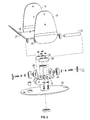
- FIG. 2 is an exploded view of the components of the unstable user support device of FIG. 1 ;
- FIG. 3 is a top plan view of the unstable user support device of FIG. 1 ;
- FIG. 4 is a cross-sectional view of the support device on the lines 4-4 of FIG. 3 , with the user support pad in a balanced position;
- FIG. 5 is a cross-sectional view similar to FIG. 3 but illustrating the user support pad tilted down on one side and contacting the rubber bumper pad or stop;
- FIG. 6 is a cross-sectional view on the lines 6-6 of FIG. 3 ;
- FIG. 7 is a front elevation view of the user support device similar to FIG. 1 but illustrating right and left tilted positions in dotted outline;
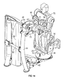
- FIG. 8 is a perspective view of a rotary torso exercise machine incorporating the unstable user support device of FIGS. 1 to 5 , with the user support device positioned in a first start position and the weight stack housing removed to reveal the exercise resistance cable routing;
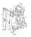
- FIG. 9 is a perspective view of the machine of FIG. 8 with the weight stack housing included and the user support device positioned in a second, oppositely directed start position for a rotary torso exercise;
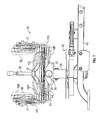
- FIG. 10 is a top plan view of the rotary torso exercise machine of FIGS. 8 and 9 ;
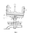
- FIG. 11 is a side elevation view of the rotary torso exercise machine in the start position of FIG. 8 , with a user in a keeling position on the user support pad ready to start an exercise;
- FIG. 12 is a side elevation view similar to FIG. 11 but with the user in an alternative start position in which they do not engage the upper torso support for an added level of core muscle engagement when performing an exercise;
- FIG. 13 is a side elevation view similar to FIG. 11 but with the user's lower torso and the user support device rotated into alignment with the upper torso and facing forward in an end position of a first rotary torso exercise;
- FIG. 14 is a front perspective view of the user and user support device in the position of FIG. 13 ;
- FIG. 15 is a side elevation view similar to FIG. 11 , but with the user support device in the second start position of FIG. 9 and a user kneeling on the user support pad and ready to perform the exercise;
- FIG. 16 is a front perspective view of the user support and user in the position of FIG. 15 ;
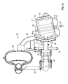
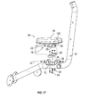
- FIG. 17 is an exploded view of a second embodiment of an unstable user support device for mounting on part of a user support member of an exercise machine;
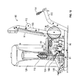
- FIG. 18 is a side elevation view of one embodiment of an arm exercise machine incorporating the unstable user support device of FIG. 17 ;
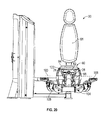
- FIG. 19 is an enlarged front elevation view of the exercise machine of FIG. 18 ;
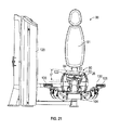
- FIG. 20 is a front elevation view similar to FIG. 19 with a front portion of the user support mounting bracket removed to reveal the bumper pads;
- FIG. 21 is a front elevation view similar to FIG. 20 illustrating the user support tilted in one direction and engaging one of the bumper pads;
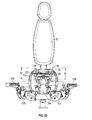
- FIG. 22 is a front elevation view similar to FIG. 20 but has an overlay illustrating tilting of the user support in both directions in dotted outline.
- Certain embodiments as disclosed herein provide for an unstable user support device which is tiltable to the left and right through a predetermined angle so that the user must exercise core muscles in order to keep the user support pad balanced in a horizontal orientation.
- the user support device is incorporated in a rotary torso exercise machine for supporting the user while they rotate their lower torso relative to their upper torso is rotatable about a vertical pivot axis, with the user support having a limited rotation about a horizontal pivot axis to produce a predetermined amount of instability in the platform so that the user has to engage core muscles to a greater extent in order to maintain the platform in a level position while rotating the lower torso.
- the user support device has a kneeling platform or support pad configured for engagement by the user in an upright kneeling position.
- the user support device is designed for supporting a user in a seated position and may be incorporated on other types of exercise machines.
- FIGS. 1 to 7 illustrate a first embodiment of an unstable user support device 10 for incorporation on a selected exercise machine, such as the rotary torso exercise machine 40 illustrated in FIGS. 8 to 16 .
- the user support device 10 is designed to support a user in a kneeling position, but it should be understood that the device may alternatively be designed for supporting users in different positions, such as seated positions, for example as shown in the second embodiment of an unstable user support device described below in connection with FIGS. 17 to 21 .
- the kneeling user support device 10 may also be incorporated on other exercise machines in which a user performs the exercise in a kneeling position.
- unstable user support device 10 basically comprises a base support or mounting bracket 12, a user support platform 14 on which a kneeling pad 15 and side support pads 16 are mounted, and a pivot connection 18 between user support platform 14 and generally U-shaped base mounting bracket 12 which rotatably secures platform 14 to mounting bracket 12 for rotation about horizontal pivot axis 20 beneath platform 14 which is aligned with the direction of the user's knees when kneeling on the user support and parallel to the plane of platform 14.
- Side support pads 16 are secured to the inner faces of respective side portions 17 of user support platform 14, as best illustrated in FIGS. 1 and 4 . As best illustrated in FIGS.
- the pivot connection 18 comprises a pivot pin 22 secured between end plates or portions 24 of mounting bracket 12 and rotatably engaged in pivot sleeve 25 secured to the lower surface of user support platform 14.
- a pair of bumper pads 26 which may be of rubber or the like are secured to the base of mounting bracket 12 on opposite sides of the pivot axis, as best illustrated in FIGS. 2 and 3 .
- Mounting bracket 12 is designed for mounting on a user support mounting post or other mounting device on an exercise machine, in place of a conventional, stable user support, such as the user support of a rotary torso machine or any other exercise machine designed for users to perform exercises in a kneeling position.
- mounting bracket 12 is secured to the upper rotating portion or turntable 28 of a user support rotational pivot 30 assembly via mounting post 60.
- Pivot assembly 30 is described in more detail below in connection with FIGS. 8 to 16 .
- An angled guide 21 with a notch 23 for receiving a rotational range adjust lever 29 of the user support rotational pivot 30 projects from the forward end of user support platform 15, as illustrated in FIGS. 2 and 3 , but guide 21 may be eliminated in alternative embodiments of the unstable user support
- the user support platform 14 of the unstable user support device 10 can pivot from side to side relative to support bracket 12 about the horizontal pivot axis 20 by an amount determined by the height of rubber bumper pads or stops 26.
- FIG. 4 illustrates a balanced, centered or 0 degrees orientation of the user support platform 14 in which the platform does not contact either bumper pad.
- the user support can pivot down to the left or the right about axis 20 through an angle of 0 to around 5 degrees in either direction before contacting a bumper pad or stop 26.
- FIG. 5 illustrates the platform 14 pivoted downwardly on the right hand side (i.e.
- FIG. 7 illustrates the end positions of the user support platform in dotted outline superimposed over the balanced position of FIG. 4 , with reference numbers ending in an R representing rotation to the right (clockwise as viewed in FIG. 7 ) and reference numbers ending in an L representing rotation to the left (anti-clockwise as viewed in FIG. 7 ).
- the user support platform in the illustrated embodiment has a degree of instability of five degrees off horizontal from side to side. A user kneeling on the user support must use core muscles in order to maintain the platform in a stable, horizontal position while performing an exercise.
- the user support platform tilts from side to side about a horizontal pivot axis extending in a front to rear direction in the illustrated embodiments
- other embodiments may have different pivot joints between platform 14 and mounting bracket 12 to allow pivoting about different pivot axes or in different planes, for example a universal joint to provide instability in all directions, or a horizontal pivot axis perpendicular to axis 20 to permit pivoting down at the front and rear of the platform 14.
- the user support platform is oriented horizontally in the illustrated embodiment, it may be slightly tilted or angled downwards or upwards when mounted on an exercise machine support structure in other embodiments, depending on the type of exercise.
- the axis 20 is not horizontal but extends parallel to the plane of the user support platform, and the platform still tilts from side to side about the axis 20.
- the user support platform pivots freely up and down between zero and five degrees on each side about pivot axis 20.
- a releasable locking mechanism may be provided to secure user support platform 14 in the horizontal orientation of FIG. 4 if a user wishes to perform the exercise without core muscle involvement.
- FIGS. 8 to 15 illustrate one embodiment of an exercise machine 40 incorporating the unstable kneeling user support device 10 of FIGS. 1 to 7 .
- User support device 10 is identical to the device shown in FIGS. 1 to 7 and described above, and like reference numbers are used for like parts as appropriate.
- the exercise machine in this case is a rotary torso machine in which the user rotates their lower torso between left and right swiveled positions relative to the upper torso, back into an aligned, front facing position relative to the upper torso.
- the user support device 10 may be used on other exercise machines for performing different exercises in other embodiments.
- Rotary torso exercise machine 40 basically comprises a main frame having a base strut 42 and a main upright 44, an upper torso stabilizing assembly 45 mounted at the upper end of main upright 44, and unstable kneeling user support device 10 mounted on rotational pivot assembly 30 supported on the base strut 42 of the main frame and configured for rotation of the user support device about vertical pivot axis 46 (see FIG. 11 ).
- exercise resistance is provided by a selectorized weight stack 48 located in weight stack housing 50 secured to the vertical upright 44 via cross bar 52 and to base strut 42 via cross member or guide tube 53.
- a selected amount of weight is secured to the rotating upper part of pivot assembly 30 via one or more cables 54 extending around various guide pulleys in a conventional manner, as illustrated in FIG. 8 .
- Other types of exercise resistance may be provided in alternative embodiments.
- Rotational pivot assembly 30 comprises a lower plate 55 secured to base strut 42 via mounting post 56, and an upper, rotating plate or turntable 28 rotatably mounted on lower plate 55 via a pivot pin at the center of plate 55 which is rotatably engaged in hollow mounting tube 60 which extends upwards from turntable 28.
- Mounting bracket 12 of the kneeling user support device 10 is secured to the upper end of mounting tube 60.
- Turntable 28 and mounting tube 60 together form the upper, rotating part of the pivot assembly 30.
- the rotational range adjustment lever 29 is pivotally secured to the mounting tube 60 and extends outwardly and upwardly at an angle from tube 60 so that it is conveniently located for gripping by a user kneeling on the platform in order to adjust the starting position for a rotary torso exercise.
- a user can adjust the user support device to a desired exercise starting position at an angle to the right or left of a forward facing position in alignment with the upper torso by gripping and pulling the handle and rotating the user support device to the desired position, as described in more detail below
- the upper torso stabilizing assembly 45 is secured to main upright 44 via four bar pivot assembly 61 and comprises a pair of stabilizing handles 62 and a pair of upper torso stabilizing pads 64 for engaging the user's chest.
- Support post 77 extends upward from a cross bar extending between the forward ends of the lower bars of pivot assembly 61, and handles 62 and pads 64 are mounted on post 77 via mounting bar 63 and cross bar 71, as best illustrated in FIGS. 8 and 9 .
- a range of motion (ROM) device 65 between the upper and lower bars of the four bar pivot assembly allows user adjustment of the height of chest pads 64 and handles 62 so that the pads are at chest level.
- Device 65 comprises ROM plate 67 also secured to support post 77 and having a series of openings 69.
- Range of adjustment knob 66 is mounted on a forward end of one of the lower bars of the pivot assembly, as illustrated in FIG. 8 , and extends into an aligned opening in ROM plate 67. Range adjustment knob 66 is released from the ROM plate 67 by a user to allow the height of the pads to be adjusted, and is then released to engage in the appropriate opening when the pads are at the desired chest level height. Gas springs 73 extend between the upper and lower bar of the four bar pivot assembly on each side of the assembly.
- FIG. 8 and 10 illustrate a first start position for a rotary torso exercise in which the user support device 10 is rotated to the left of a central position in alignment with the upper torso stabilizing assembly 45.
- the central position is illustrated in FIG. 13 and 14 with a user 70 kneeling on the user support and engaging the upper torso stabilizing assembly.
- the user support device 10 faces the main upright and the lower torso of a user kneeling on the support pad 15 is aligned with the upper torso.
- FIG. 9 illustrates a second start position for a rotary torso exercise in which the user support device 10 is rotated to the right of the central position.
- the start position may be adjusted by the user by gripping the handle of adjustment lever 29, pulling it towards their body so as to lift pin 72 ( FIGS. 11-13 ) out of slot 73 or 74 in the lower fixed plate or base plate 55 of pivot assembly 30, then rotating the user support device into the desired adjusted position and releasing the lever 29 so that the pin 72 drops back into aligned slot 73 or 74.
- the angular length of slots 73 and 74 controls the amount of rotation of the lower torso relative to the upper torso.
- the user 70 In order to perform the exercise, the user 70 first adjusts the kneeling user support device 10 to the desired starting position, i.e. degrees of exercise range to rotate lower torso to face forward alignment with upper torso. Exercise is performed in one direction, starting either from the position of FIG. 8 or FIG. 9 , then the user re-adjusts the platform or support device 10 to exercise in the opposite direction. Once the user support device 10 is in the desired start position, user 70 assumes a kneeling upright position on the keeling platform, as illustrated in FIG. 11 for the starting position of FIGS. 8 and 10 . Note that the kneeling platform rocks side to side about axis 20 during this positioning, which requires balancing using core muscles to keep level.
- the desired starting position i.e. degrees of exercise range to rotate lower torso to face forward alignment with upper torso.
- Exercise is performed in one direction, starting either from the position of FIG. 8 or FIG. 9 , then the user re-adjusts the platform or support device 10 to exercise in
- the upper torso stabilizing pads / handles assembly 45 is then adjusted so the pads 64 are at chest level, using ROM device 65. Once the pads are locked in position, the user grasps the handles and pulls their chest tight to pads for stabilization, as illustrated in FIG. 11 .
- the exercise may be performed using handles 62 only to stabilize the upper torso, keeping the chest off the pads 64 during the exercise, as illustrated in FIG. 12 . This provides an added level of core engagement.
- the user's tower torso is in a rotated away position from the upper torso.
- the lower torso is rotated to the left relative to the upper torso.
- the user rotates the lower torso into alignment with the stabilized face forward position of the upper torso, using a slow controlled movement, and ending up in the end position of FIGS. 13 and 14 .
- the user exercises core muscles in order to keep the kneeling platform 14 of unstable user support device 10 balanced during the movement.
- the lower torso and user support device are then rotated back to the starting position of FIG. 11 and the exercise is repeated for the desired number of repetitions.
- the platform is then readjusted to the opposite starting position of FIG. 9 , the user 70 kneels back on the kneeling pad 15 in the position of FIGS. 15 and 16 , and again grips the handles 42 and pulls the chest pads 64 in to their chest.
- the lower torso is rotated to the right of the upper torso. They then rotate their lower body on the user support device 10 back into the forward facing end position of FIGS. 13 and 14 , and the exercise is repeated for the desired number of repetitions.
- Load bearing cable 54 linked to the selected number of weights in weight stack 48 provides the desired amount of resistance to rotation of the user support device between either start position and the end position.
- the kneeling platform or user support device 10 is designed to provide a level of instability for the purpose of greater challenging the core muscles to balance the platform while performing the exercise motion.
- the kneeling platform instability may be provided in any or all planes to aid in engaging the core muscles.
- the unstable plane selection for the user support device of FIGS. 1 to 16 is left to right or side to side.
- the degree of instability is approximately 5 degrees off horizontal, left or right.
- the rubber bumper pads 26 ( FIG. 4 , 5 and 7 ) contact the undersurface of the platform when tilted through five degrees to the left or right, limiting the amount of instability.
- Different degrees of instability may be provided in alternative embodiments by bumper pads of different heights, for example the platform may be tiltable through an angle in the range of about 3 to 10 degrees off horizontal.
- the more weight stack resistance selected the greater degree of aided core muscle engagement necessary to keep the kneeling platform balanced.
- the handles alone may be used to stabilize the upper torso while keeping the chest off the pads during the exercise motion.
- the unstable user support device 10 in the previous embodiment is designed to support a user in an upright kneeling position.
- the unstable user support device may be designed to support users in different positions, such as seated positions.
- FIG. 17 illustrates a second embodiment of an unstable user support device 80 which is designed for supporting a seated user.
- Device 80 may be used to replace a stable user support seat on an exercise machine designed for supporting a seated user.
- FIG. 17 is an exploded view showing device 80 ready for mounting on a base support strut or arm 81 of an exercise machine in place of a conventional, fixed user support or seat.
- Some examples of exercise machines on which unstable seated user support device 80 may be used are upper body exercise machines such as biceps curl exercise machines, seated mid row exercise machines, pec fly exercise machines, and chest press and shoulder press exercise machines.
- Some examples of such exercise machines on which unstable user support device 80 may be used are the RS-1102 biceps curl exercise machine, the RS-1203 seated mid row exercise machine, the RS-1302 pec fly exercise machine, the RPL-5301 chest press exercise machine, and the RS-1501 and RPL-5501 shoulder press exercise machines which all have rocking seats and are manufactured by Hoist Fitness Systems, Inc. of San Diego, California, or any of the rocking user support exercise machines described in US Pat. Nos.
- the unstable user support device 80 may also be used on other types of exercise machines with rocking and non-rocking seated user supports in alternative embodiments.
- Unstable user support device 80 is similar to the unstable kneeling user support device 10 of the previous embodiment, and like reference numbers are used for like parts as appropriate. The main difference is the replacement of the kneeling support platform and pads with seated support platform 82 on which seat pad 84 is mounted. Seated support platform is mounted on base support or mounting bracket 12 via pivot connection 18 which rotatably secures platform 82 to mounting bracket 12 for rotation about a pivot axis 20 directed between the front and rear ends of the user support device, so that the seated support platform rocks from side to side as in the previous embodiment.
- the pivot connection 18 comprises a pivot pin 22 secured between end portions 24 of mounting bracket 12 and rotatably engaged in pivot sleeve 25 secured to the lower surface of user support platform 82 via mounting bracket 12.
- Rubber bumper pads 26 are secured on opposite sides of the pivot axis by fasteners 83, and control the range of pivoting of the seat as in the previous embodiment. Pads 26 may also be positioned so that the seat rocks through about five degrees from the horizontal orientation on each side before engaging the respective bumper pad.
- Mounting bracket 12 is secured in a seat on the upper surface of support post or base support strut 81 by welding, bolting or the like, so that unstable user support device 80 can be used on an exercise machine in place of the standard stable seated user support, as described below for one type of exercise machine.
- FIGS. 18 to 22 illustrate unstable user support device 80 of FIG. 17 installed on a biceps curl exercise machine 90 for supporting a seated user while performing biceps curl exercises.
- the unstable seated user support platform or device 80 may be used in conjunction with a back rest or back pad 91 as illustrated, or may be used on its own, depending on the type of exercise involved.
- arm exercise machine 90 has a rocking user support, but it will be understood that unstable user support device 80 may be installed on any exercise machine designed for engagement by a user in a seated position.
- exercise machine 90 of FIGS. 18 to 22 is the same as the RS-1102 Biceps Curl Exercise Machine of Hoist Fitness Systems, Inc. of San Diego, California, as referenced above.
- Machine 90 includes a main frame and a user support assembly including a seat support tube or frame 81 pivotally mounted on the base strut 96 of the main frame by means of pivot mount 98 for rearward and forward rotation about horizontal pivot axis 100 (see FIG. 20 ).
- the seat support tube or frame 81 is generally "L" shaped, with a rear upright 103 and a forwardly extending leg 104 with foot rests 105 mounted at the forward end of leg 104.
- Back pad 91 is mounted on the rear upright 103.
- a seat pad is mounted at a fixed position on a mounting post on the forwardly extending leg 104 of the user support tube, at the appropriate position relative to the back pad 91.
- a telescopic mounting arrangement may be used to allow the height of the seat pad to be adjusted, but the seat pad in the existing machine is otherwise fixed in position relative to the seat support tube and back pad.
- the existing seat pad is removed from the telescopic mounting post and replaced by unstable user support device 80 which is mounted on leg 104 as illustrated in FIG. 17 , at a location spaced forward from rear upright 103.
- Mounting bracket 12 may alternatively be adjustably mounted on leg 104 for adjusting the height of seat pad 84.
- User engageable handles 106 on each side of the user support assembly are secured to ends of a cable exercise arm assembly including at least one cable (not illustrated) extending between the handles in a selected cable route which includes first and second dual diameter double pulleys or cams 110, 116 on opposite sides of the user support, a pair of pulleys 112 on rear upright 103 of the user support assembly, and a rear pulley 114 on main frame rear upright 115.
- a weight stack 118 housed in a vertical weight stack housing 120 provides exercise resistance. The weight stack 118 is linked to the user support assembly by a cable and pulley linkage.
- the arrangement is such that pulling up on handles 106 in a biceps curl exercise simultaneously rocks the user support assembly rearwards about pivot axis 100 against the exercise resistance, between the generally upright position of FIG. 18 into a rearwardly reclined position.
- the unstable user seat pad is free to tilt from side to side about instability pivot axis 20 which extends perpendicular to the rocking user support pivot axis 100, as seen in FIG. 19 to 22 .
- the user seated on seat pad 84 engages core muscles to balance the seat platform in a stable, central position while performing a biceps curl exercise
- FIGS. 20 to 22 the front end portion or plate 24 of mounting bracket 12 is removed to reveal the bumper pads 26.
- the user support platform 82 is in a centered, 0 degree orientation in FIG. 20 .
- FIG. 21 illustrates the seat tilted down on the seated user's left hand side until the lower part or pivot sleeve mounting bracket 122 at the bottom of platform 82 on one side of pivot sleeve 25 contacts bumper 26.
- FIG. 22 illustrates left and right downwardly tilted unstable positions in dotted outline.
- the user support can pivot down to the left or the right about axis 20 through an angle of 0 to around 5 degrees in either direction before contacting a bumper pad or stop 26.
- seated user support platform 82 in the illustrated embodiment has a degree of instability of five degrees off a level or centered orientation from side to side.
- the seat starts from a horizontal centered orientation in FIG. 20 , it will be understood that the same side-to-side instabality continues throughout an exercise as the user support tilts rearward about axis 100 during the exercise.
- a user seated on the user support pad 84 and performing biceps curl exercises on the machine 90 uses core muscles in order to maintain the platform in a stable, level position while performing the exercise, while the user support assembly simultaneously tilts rearward about pivot axis 100.
- the unstable user support devices described above allow for tilting of a user support platform from side to side through a limited angle, so as to involve core muscles to stabilize the support platform while performing various types of exercises, including exercises performed in kneeling and seated positions.
- tilting is from side to side in the described embodiments, tilting about different axes may be provided in alternative embodiments, including an alternative embodiment with a universal or multi-directional pivot connection between the mounting bracket or base and the user support platform.
- the instability of the user support platform may therefore be provided in multiple directions or planes, and through any desired angular range.
- the instability of the user support platform challenges the core muscles in balancing the platform while performing the exercise, providing enhanced exercise and training.
- the pivot axis is parallel to the user support platform.
- the stop assembly comprises first and second end stops defining the respective first and second end positions.
- the end stops comprise resilient bumpers mounted on one of the base and the user support platform on opposite sides of the pivot axis.
- the resilient bumpers are mounted on the base.
- the predetermined angular range is from zero to approximately 5 degrees.
- the pivotal connection defines at least two non-vertical pivot axes.
- the pivotal connection is a universal joint configured for tilting of the user support platform in multiple directions from the centered support position.
- the user support platform has at least one user support pad having a rear end, a forward end, and a central axis between the rear and forward ends, and the user support pad is configured for engagement by a user's knees and lower legs on opposite sides of the central axis with the user in a kneeling position.
- the pivot axis is parallel to the central axis of the user support pad and configured for side-to-side tilting movement of the support platform to the right and left of the centered support position.
- the user support platform has at least one user support pad configured to support a user in a seated position.
- a rotary torso exercise machine which can comprise a main frame, a lower torso support rotatably mounted on the frame for rotation about a first, vertical axis between a forward facing position and opposite left and right swiveled positions, the lower torso support confired to support a lower torso of a user an upper torso support mounted on the frame for supporting the upper torso of the user in a fixed position while the lower torso is rotated
- the lower torso support can comprise a base mounted on the frame for rotation about the first, vertical axis between left and right swiveled positions and the forward facing position, and an unstable user support platform pivotally mounted on the base for rotation in at least two opposite directions between a centered orientation and first and second tilted orientations about at least one second, non-vertical pivot axis and a stop assembly between the base and user support platform configured to limit tilting of the user support platform to a predetermined angular range between the centered position and each tilted orientation.
- the left and right swiveled positions are adjustable to provide adjustable left and right starting positions for a user's lower torso when performing a rotary torso exercise.
- the exercise machine can further comprise a load which resists rotation of the user support from the left or right starting position to the forward facing position.
- the second pivot axis is horizontal and the centered orientation of the user support platform lies in a horizontal plane.
- the stop assembly can comprise first and second end stops defining the respective first and second tilted orientations.
- the end stops can comprise resilient bumpers mounted on one of the base and the user support platform on opposite sides of the second pivot axis.
- the resilient bumpers are mounted on the base.
- the predetermined angular range is from zero to approximately 5 degrees.
- the pivotal connection defines at least two non-vertical pivot axes.
- the pivotal connection is a universal joint configured for tilting of the user support platform in multiple directions from a centered horizontal orientation.
- the user support platform has at least one user support pad having knee support portions configured to support a user's knees and at least part of the user's lower legs with the user in a kneeling position, and defining a center line of the pad extending between the knee support portions.
- the pivot axis is beneath and parallel to the center line of the user support pad and configured for side-to-side tilting movement of the support platform to the right and left of the centered orientation.
- an exercise machine which can comprise a stationary main frame having a forward end, a rear end, and opposite sides an exercise arm assembly movably mounted relative to the main frame and having a user engaging portion which adapted for engagement by a part of a user's body to perform an exercise when a user is supported in an exercise position on the user support assembly a user support assembly mounted on the main frame and adapted to support a user in an exercise position during an exercise the user support assembly can comprise a base pivotally mounted on the main frame for rotation above a first pivot axis, an unstable user support platform, and a pivot connection between the user support platform and the base configured for allowing free rotation of the user support platform about at least one non-vertical tilting pivot axis in at least two opposite directions between a centered user support position and first and second tilted end positions and a stop assembly between the base and user support platform which defines the respective first and second end positions and limits tilting movement from said centered support position in each direction to a predetermined angular range.
- the first pivot axis is perpendicular to the tilting pivot axis of the user support platform.
- the exercise machine can further comprise a connecting linkage between the user support assembly and exercise arm assembly which links movement of the exercise arm assembly during an exercise to movement of the user support assembly about said second pivot axis, and a load which resists movement of at least one of the user support assembly, the exercise arm assembly and the connecting linkage.
- the pivot axes are horizontal pivot axes.
- the stop assembly comprises first and second end stops defining the respective first and second end positions.
- the tilting pivot axis is in a plane parallel to the user support platform and the end stops comprise resilient bumpers mounted on one of the base and the user support platform on opposite sides of the tilting pivot axis.
- the resilient bumpers are mounted on the base.
- the predetermined angular range is from zero to at least approximately 5 degrees.
- the pivot connection between the base and the user support platform defines at least two non-vertical tilting pivot axes.
- the pivotal connection is a universal joint configured for tilting of the user support platform in multiple directions from the centered user support position.
- the user support platform has at least one user seat pad configured to support a user in a seated position in a generally forward facing direction.
- the tilting pivot axis extends beneath the support platform in a plane parallel to the user support platform in a direction generally towards the forward end of the main frame at a start position of an exercise, and is configured for side-to-side tilting movement of the user support platform to the right and left of the centered user support position.
- the first pivot axis extends perpendicular to the tilting pivot axis.
- the base comprises a base portion on which said user support platform is pivotally mounted and a back support portion extending upwardly at an angle to the base portion, the user support further comprising a back pad on the back support portion configured for supporting a user's back.
Abstract
Description
- This invention relates generally to exercise machines and is particularly concerned with an unstable user support for an exercise machine which is designed to involve additional core muscles in holding the support steady while exercising.
- User supports which support an exerciser in seated, prone, kneeling, or upright positions while performing an exercise on an exercise machine are known. Such supports may be stationary, or may be designed to rock during an exercise. In a rotary torso exercise machine, a user support is mounted for rotation about a vertical axis and the user rotates their lower torso relative to their upper torso to the right and left of a central position.
- In one aspect, an unstable user support for supporting a user in a seated or kneeling position while performing an exercise on an exercise machine is provided, which comprises a base, a user support platform pivotally mounted on the base for side to side pivoting motion about a pivot axis beneath the user support platform, and a pair of bumper pads on the base on opposite sides of the pivot axis for engaging the user support pad to limit rotation of the user support pad in each direction to a predetermined angular range. In one embodiment, the angular range may be around 5 degrees from the horizontal orientation.
- The user support platform may be designed for supporting a user in a seated position in one embodiment, or a kneeling position in another embodiment. In one embodiment, the unstable user support is designed for supporting a user in a kneeling position, and may be provided on a rotary torso exercise machine. The rotary torso machine in one embodiment comprises a main frame, a user lower torso support rotatably mounted on the frame for rotation about a first, vertical axis, and an upper torso support mounted on the frame for supporting the upper torso in a fixed position while the lower torso is rotated. The lower torso support is an unstable user support and is also pivotally mounted for limited rotation about a horizontal pivot axis so that the user has to balance the support while performing the rotating or twisting exercise motion. This produces a greater engagement of the user's core muscles in maintaining the user support in a horizontal plane while rotating their lower torso about a central vertical axis.
- In another embodiment, an unstable user support may be provided on any one of a plurality of different upper torso machines to support a user in a seated position while performing an upper torso exercise, so the user employs core muscles to hold the seat level while exercising selected upper torso muscles. The unstable user support may be provided on an arm exercise machine, a shoulder press exercise machine, a chest exercise machine, a pec fly exercise machine, or a seated mid row exercise machine, or other types of exercise machine in which the user is supported in a seated or kneeling position. Unstable user supports may also be designed in a similar way for supporting users in other exercise positions in other alternative embodiments, such as prone or standing positions.
- The details of the present invention, both as to its structure and operation, may be gleaned in part by study of the accompanying drawings, in which like reference numerals refer to like parts, and in which:
-
FIG. 1 is a front elevation view of an unstable user support device according to a first embodiment for supporting a user in a kneeling position; -
FIG. 2 is an exploded view of the components of the unstable user support device ofFIG. 1 ; -
FIG. 3 is a top plan view of the unstable user support device ofFIG. 1 ; -
FIG. 4 is a cross-sectional view of the support device on the lines 4-4 ofFIG. 3 , with the user support pad in a balanced position; -
FIG. 5 is a cross-sectional view similar toFIG. 3 but illustrating the user support pad tilted down on one side and contacting the rubber bumper pad or stop; -
FIG. 6 is a cross-sectional view on the lines 6-6 ofFIG. 3 ; -
FIG. 7 is a front elevation view of the user support device similar toFIG. 1 but illustrating right and left tilted positions in dotted outline; -
FIG. 8 is a perspective view of a rotary torso exercise machine incorporating the unstable user support device ofFIGS. 1 to 5 , with the user support device positioned in a first start position and the weight stack housing removed to reveal the exercise resistance cable routing; -
FIG. 9 is a perspective view of the machine ofFIG. 8 with the weight stack housing included and the user support device positioned in a second, oppositely directed start position for a rotary torso exercise; -
FIG. 10 is a top plan view of the rotary torso exercise machine ofFIGS. 8 and9 ; -
FIG. 11 is a side elevation view of the rotary torso exercise machine in the start position ofFIG. 8 , with a user in a keeling position on the user support pad ready to start an exercise; -
FIG. 12 is a side elevation view similar toFIG. 11 but with the user in an alternative start position in which they do not engage the upper torso support for an added level of core muscle engagement when performing an exercise; -
FIG. 13 is a side elevation view similar toFIG. 11 but with the user's lower torso and the user support device rotated into alignment with the upper torso and facing forward in an end position of a first rotary torso exercise; -
FIG. 14 is a front perspective view of the user and user support device in the position ofFIG. 13 ; -
FIG. 15 is a side elevation view similar toFIG. 11 , but with the user support device in the second start position ofFIG. 9 and a user kneeling on the user support pad and ready to perform the exercise; -
FIG. 16 is a front perspective view of the user support and user in the position ofFIG. 15 ; -
FIG. 17 is an exploded view of a second embodiment of an unstable user support device for mounting on part of a user support member of an exercise machine; -
FIG. 18 is a side elevation view of one embodiment of an arm exercise machine incorporating the unstable user support device ofFIG. 17 ; -
FIG. 19 is an enlarged front elevation view of the exercise machine ofFIG. 18 ; -
FIG. 20 is a front elevation view similar toFIG. 19 with a front portion of the user support mounting bracket removed to reveal the bumper pads; -
FIG. 21 is a front elevation view similar toFIG. 20 illustrating the user support tilted in one direction and engaging one of the bumper pads; and -
FIG. 22 is a front elevation view similar toFIG. 20 but has an overlay illustrating tilting of the user support in both directions in dotted outline. - Certain embodiments as disclosed herein provide for an unstable user support device which is tiltable to the left and right through a predetermined angle so that the user must exercise core muscles in order to keep the user support pad balanced in a horizontal orientation. In one embodiment, the user support device is incorporated in a rotary torso exercise machine for supporting the user while they rotate their lower torso relative to their upper torso is rotatable about a vertical pivot axis, with the user support having a limited rotation about a horizontal pivot axis to produce a predetermined amount of instability in the platform so that the user has to engage core muscles to a greater extent in order to maintain the platform in a level position while rotating the lower torso. In one embodiment, the user support device has a kneeling platform or support pad configured for engagement by the user in an upright kneeling position. In alternative embodiments, the user support device is designed for supporting a user in a seated position and may be incorporated on other types of exercise machines.
- After reading this description it will become apparent to one skilled in the art how to implement the invention in various alternative embodiments and alternative applications. However, although various embodiments of the present invention will be described herein, it is understood that these embodiments are presented by way of example only, and not limitation.
-
FIGS. 1 to 7 illustrate a first embodiment of an unstableuser support device 10 for incorporation on a selected exercise machine, such as the rotarytorso exercise machine 40 illustrated inFIGS. 8 to 16 . Theuser support device 10 is designed to support a user in a kneeling position, but it should be understood that the device may alternatively be designed for supporting users in different positions, such as seated positions, for example as shown in the second embodiment of an unstable user support device described below in connection withFIGS. 17 to 21 . The kneelinguser support device 10 may also be incorporated on other exercise machines in which a user performs the exercise in a kneeling position. - As illustrated in
FIGS. 1 to 7 , unstableuser support device 10 basically comprises a base support ormounting bracket 12, auser support platform 14 on which a kneelingpad 15 andside support pads 16 are mounted, and apivot connection 18 betweenuser support platform 14 and generally U-shapedbase mounting bracket 12 which rotatably securesplatform 14 to mountingbracket 12 for rotation abouthorizontal pivot axis 20 beneathplatform 14 which is aligned with the direction of the user's knees when kneeling on the user support and parallel to the plane ofplatform 14.Side support pads 16 are secured to the inner faces ofrespective side portions 17 ofuser support platform 14, as best illustrated inFIGS. 1 and4 . As best illustrated inFIGS. 2 and4 , thepivot connection 18 comprises apivot pin 22 secured between end plates orportions 24 ofmounting bracket 12 and rotatably engaged inpivot sleeve 25 secured to the lower surface ofuser support platform 14. A pair ofbumper pads 26 which may be of rubber or the like are secured to the base ofmounting bracket 12 on opposite sides of the pivot axis, as best illustrated inFIGS. 2 and3 . -
Mounting bracket 12 is designed for mounting on a user support mounting post or other mounting device on an exercise machine, in place of a conventional, stable user support, such as the user support of a rotary torso machine or any other exercise machine designed for users to perform exercises in a kneeling position. In the illustrated embodiment,mounting bracket 12 is secured to the upper rotating portion orturntable 28 of a user supportrotational pivot 30 assembly viamounting post 60.Pivot assembly 30 is described in more detail below in connection withFIGS. 8 to 16 . Anangled guide 21 with anotch 23 for receiving a rotational range adjustlever 29 of the user supportrotational pivot 30 projects from the forward end ofuser support platform 15, as illustrated inFIGS. 2 and3 , butguide 21 may be eliminated in alternative embodiments of the unstable user support - The
user support platform 14 of the unstableuser support device 10 can pivot from side to side relative to supportbracket 12 about thehorizontal pivot axis 20 by an amount determined by the height of rubber bumper pads or stops 26.FIG. 4 illustrates a balanced, centered or 0 degrees orientation of theuser support platform 14 in which the platform does not contact either bumper pad. In the illustrated embodiment, the user support can pivot down to the left or the right aboutaxis 20 through an angle of 0 to around 5 degrees in either direction before contacting a bumper pad or stop 26.FIG. 5 illustrates theplatform 14 pivoted downwardly on the right hand side (i.e. the right hand side of a user kneeling on the user support pad facing in a forward direction) through 5 degrees, with the lower surface ofplatform 14 contacting the righthand bumper pad 26 to limit the downward rotation to about five degrees. The platform can similarly pivot downwardly on the left hand side to contact the left hand bumper pad.FIG. 7 illustrates the end positions of the user support platform in dotted outline superimposed over the balanced position ofFIG. 4 , with reference numbers ending in an R representing rotation to the right (clockwise as viewed inFIG. 7 ) and reference numbers ending in an L representing rotation to the left (anti-clockwise as viewed inFIG. 7 ). Thus, the user support platform in the illustrated embodiment has a degree of instability of five degrees off horizontal from side to side. A user kneeling on the user support must use core muscles in order to maintain the platform in a stable, horizontal position while performing an exercise. - Although the user support platform tilts from side to side about a horizontal pivot axis extending in a front to rear direction in the illustrated embodiments, other embodiments may have different pivot joints between
platform 14 and mountingbracket 12 to allow pivoting about different pivot axes or in different planes, for example a universal joint to provide instability in all directions, or a horizontal pivot axis perpendicular toaxis 20 to permit pivoting down at the front and rear of theplatform 14. Additionally, although the user support platform is oriented horizontally in the illustrated embodiment, it may be slightly tilted or angled downwards or upwards when mounted on an exercise machine support structure in other embodiments, depending on the type of exercise. In such alternatives, theaxis 20 is not horizontal but extends parallel to the plane of the user support platform, and the platform still tilts from side to side about theaxis 20. - In the illustrated embodiment, the user support platform pivots freely up and down between zero and five degrees on each side about
pivot axis 20. In an alternative embodiment, a releasable locking mechanism may be provided to secureuser support platform 14 in the horizontal orientation ofFIG. 4 if a user wishes to perform the exercise without core muscle involvement. -
FIGS. 8 to 15 illustrate one embodiment of anexercise machine 40 incorporating the unstable kneelinguser support device 10 ofFIGS. 1 to 7 .User support device 10 is identical to the device shown inFIGS. 1 to 7 and described above, and like reference numbers are used for like parts as appropriate. The exercise machine in this case is a rotary torso machine in which the user rotates their lower torso between left and right swiveled positions relative to the upper torso, back into an aligned, front facing position relative to the upper torso. However, it will be understood that theuser support device 10 may be used on other exercise machines for performing different exercises in other embodiments. - Rotary
torso exercise machine 40 basically comprises a main frame having abase strut 42 and amain upright 44, an uppertorso stabilizing assembly 45 mounted at the upper end ofmain upright 44, and unstable kneelinguser support device 10 mounted onrotational pivot assembly 30 supported on thebase strut 42 of the main frame and configured for rotation of the user support device about vertical pivot axis 46 (seeFIG. 11 ). In this embodiment, exercise resistance is provided by aselectorized weight stack 48 located inweight stack housing 50 secured to thevertical upright 44 viacross bar 52 and tobase strut 42 via cross member or guidetube 53. A selected amount of weight is secured to the rotating upper part ofpivot assembly 30 via one ormore cables 54 extending around various guide pulleys in a conventional manner, as illustrated inFIG. 8 . Other types of exercise resistance may be provided in alternative embodiments. -
Rotational pivot assembly 30 comprises alower plate 55 secured tobase strut 42 via mountingpost 56, and an upper, rotating plate orturntable 28 rotatably mounted onlower plate 55 via a pivot pin at the center ofplate 55 which is rotatably engaged in hollow mountingtube 60 which extends upwards fromturntable 28. Mountingbracket 12 of the kneelinguser support device 10 is secured to the upper end of mountingtube 60.Turntable 28 and mountingtube 60 together form the upper, rotating part of thepivot assembly 30. The rotationalrange adjustment lever 29 is pivotally secured to the mountingtube 60 and extends outwardly and upwardly at an angle fromtube 60 so that it is conveniently located for gripping by a user kneeling on the platform in order to adjust the starting position for a rotary torso exercise. A user can adjust the user support device to a desired exercise starting position at an angle to the right or left of a forward facing position in alignment with the upper torso by gripping and pulling the handle and rotating the user support device to the desired position, as described in more detail below. - The upper
torso stabilizing assembly 45 is secured tomain upright 44 via fourbar pivot assembly 61 and comprises a pair of stabilizinghandles 62 and a pair of uppertorso stabilizing pads 64 for engaging the user's chest.Support post 77 extends upward from a cross bar extending between the forward ends of the lower bars ofpivot assembly 61, and handles 62 andpads 64 are mounted onpost 77 via mountingbar 63 andcross bar 71, as best illustrated inFIGS. 8 and9 . A range of motion (ROM)device 65 between the upper and lower bars of the four bar pivot assembly allows user adjustment of the height ofchest pads 64 and handles 62 so that the pads are at chest level.Device 65 comprisesROM plate 67 also secured to supportpost 77 and having a series ofopenings 69. Range ofadjustment knob 66 is mounted on a forward end of one of the lower bars of the pivot assembly, as illustrated inFIG. 8 , and extends into an aligned opening inROM plate 67.Range adjustment knob 66 is released from theROM plate 67 by a user to allow the height of the pads to be adjusted, and is then released to engage in the appropriate opening when the pads are at the desired chest level height. Gas springs 73 extend between the upper and lower bar of the four bar pivot assembly on each side of the assembly. -
FIG. 8 and10 illustrate a first start position for a rotary torso exercise in which theuser support device 10 is rotated to the left of a central position in alignment with the uppertorso stabilizing assembly 45. The central position is illustrated inFIG. 13 and14 with auser 70 kneeling on the user support and engaging the upper torso stabilizing assembly. In the central position, theuser support device 10 faces the main upright and the lower torso of a user kneeling on thesupport pad 15 is aligned with the upper torso.FIG. 9 illustrates a second start position for a rotary torso exercise in which theuser support device 10 is rotated to the right of the central position. The start position may be adjusted by the user by gripping the handle ofadjustment lever 29, pulling it towards their body so as to lift pin 72 (FIGS. 11-13 ) out ofslot base plate 55 ofpivot assembly 30, then rotating the user support device into the desired adjusted position and releasing thelever 29 so that thepin 72 drops back into alignedslot slots - In order to perform the exercise, the
user 70 first adjusts the kneelinguser support device 10 to the desired starting position, i.e. degrees of exercise range to rotate lower torso to face forward alignment with upper torso. Exercise is performed in one direction, starting either from the position ofFIG. 8 orFIG. 9 , then the user re-adjusts the platform orsupport device 10 to exercise in the opposite direction. Once theuser support device 10 is in the desired start position,user 70 assumes a kneeling upright position on the keeling platform, as illustrated inFIG. 11 for the starting position ofFIGS. 8 and10 . Note that the kneeling platform rocks side to side aboutaxis 20 during this positioning, which requires balancing using core muscles to keep level. - The upper torso stabilizing pads /
handles assembly 45 is then adjusted so thepads 64 are at chest level, usingROM device 65. Once the pads are locked in position, the user grasps the handles and pulls their chest tight to pads for stabilization, as illustrated inFIG. 11 . Alternatively, the exercise may be performed usinghandles 62 only to stabilize the upper torso, keeping the chest off thepads 64 during the exercise, as illustrated inFIG. 12 . This provides an added level of core engagement. - Once the user is properly positioned on the kneeling platform or
user support device 10, while grippinghandles 62 and optionally engaging the chest pads of the uppertorso support assembly 45, the user's tower torso is in a rotated away position from the upper torso. In the start position ofFIG. 12 , the lower torso is rotated to the left relative to the upper torso. In order to perform the exercise motion, the user rotates the lower torso into alignment with the stabilized face forward position of the upper torso, using a slow controlled movement, and ending up in the end position ofFIGS. 13 and14 . During this movement, the user exercises core muscles in order to keep the kneelingplatform 14 of unstableuser support device 10 balanced during the movement. The lower torso and user support device are then rotated back to the starting position ofFIG. 11 and the exercise is repeated for the desired number of repetitions. The platform is then readjusted to the opposite starting position ofFIG. 9 , theuser 70 kneels back on thekneeling pad 15 in the position ofFIGS. 15 and16 , and again grips thehandles 42 and pulls thechest pads 64 in to their chest. In this start position, the lower torso is rotated to the right of the upper torso. They then rotate their lower body on theuser support device 10 back into the forward facing end position ofFIGS. 13 and14 , and the exercise is repeated for the desired number of repetitions.Load bearing cable 54 linked to the selected number of weights inweight stack 48 provides the desired amount of resistance to rotation of the user support device between either start position and the end position. - The kneeling platform or
user support device 10 is designed to provide a level of instability for the purpose of greater challenging the core muscles to balance the platform while performing the exercise motion. The kneeling platform instability may be provided in any or all planes to aid in engaging the core muscles. The unstable plane selection for the user support device ofFIGS. 1 to 16 is left to right or side to side. The degree of instability is approximately 5 degrees off horizontal, left or right. The rubber bumper pads 26 (FIG. 4 ,5 and7 ) contact the undersurface of the platform when tilted through five degrees to the left or right, limiting the amount of instability. Different degrees of instability may be provided in alternative embodiments by bumper pads of different heights, for example the platform may be tiltable through an angle in the range of about 3 to 10 degrees off horizontal. The more weight stack resistance selected, the greater degree of aided core muscle engagement necessary to keep the kneeling platform balanced. For an added level of core engagement, the handles alone may be used to stabilize the upper torso while keeping the chest off the pads during the exercise motion. - The unstable
user support device 10 in the previous embodiment is designed to support a user in an upright kneeling position. In alternative embodiments, the unstable user support device may be designed to support users in different positions, such as seated positions.FIG. 17 illustrates a second embodiment of an unstableuser support device 80 which is designed for supporting a seated user.Device 80 may be used to replace a stable user support seat on an exercise machine designed for supporting a seated user.FIG. 17 is an explodedview showing device 80 ready for mounting on a base support strut orarm 81 of an exercise machine in place of a conventional, fixed user support or seat. - Some examples of exercise machines on which unstable seated
user support device 80 may be used are upper body exercise machines such as biceps curl exercise machines, seated mid row exercise machines, pec fly exercise machines, and chest press and shoulder press exercise machines. Some examples of such exercise machines on which unstableuser support device 80 may be used are the RS-1102 biceps curl exercise machine, the RS-1203 seated mid row exercise machine, the RS-1302 pec fly exercise machine, the RPL-5301 chest press exercise machine, and the RS-1501 and RPL-5501 shoulder press exercise machines which all have rocking seats and are manufactured by Hoist Fitness Systems, Inc. of San Diego, California, or any of the rocking user support exercise machines described inUS Pat. Nos. 7,717,832 ,7,760,269 ,7,766,802 ,7,794,371 ,7,901,337 ,7,938,760 ,7,976,440 ,7,981,010 ,7,993,251 , and8,002,679 of Hoist Fitness Systems, Inc.. The unstableuser support device 80 may also be used on other types of exercise machines with rocking and non-rocking seated user supports in alternative embodiments. - Unstable
user support device 80 is similar to the unstable kneelinguser support device 10 of the previous embodiment, and like reference numbers are used for like parts as appropriate. The main difference is the replacement of the kneeling support platform and pads withseated support platform 82 on whichseat pad 84 is mounted. Seated support platform is mounted on base support or mountingbracket 12 viapivot connection 18 which rotatably securesplatform 82 to mountingbracket 12 for rotation about apivot axis 20 directed between the front and rear ends of the user support device, so that the seated support platform rocks from side to side as in the previous embodiment. As in the previous embodiment, thepivot connection 18 comprises apivot pin 22 secured betweenend portions 24 of mountingbracket 12 and rotatably engaged inpivot sleeve 25 secured to the lower surface ofuser support platform 82 via mountingbracket 12.Rubber bumper pads 26 are secured on opposite sides of the pivot axis byfasteners 83, and control the range of pivoting of the seat as in the previous embodiment.Pads 26 may also be positioned so that the seat rocks through about five degrees from the horizontal orientation on each side before engaging the respective bumper pad. Mountingbracket 12 is secured in a seat on the upper surface of support post orbase support strut 81 by welding, bolting or the like, so that unstableuser support device 80 can be used on an exercise machine in place of the standard stable seated user support, as described below for one type of exercise machine. -
FIGS. 18 to 22 illustrate unstableuser support device 80 ofFIG. 17 installed on a bicepscurl exercise machine 90 for supporting a seated user while performing biceps curl exercises. The unstable seated user support platform ordevice 80 may be used in conjunction with a back rest or backpad 91 as illustrated, or may be used on its own, depending on the type of exercise involved. In the illustrated embodiment,arm exercise machine 90 has a rocking user support, but it will be understood that unstableuser support device 80 may be installed on any exercise machine designed for engagement by a user in a seated position. Apart from the unstableuser support device 80,exercise machine 90 ofFIGS. 18 to 22 is the same as the RS-1102 Biceps Curl Exercise Machine of Hoist Fitness Systems, Inc. of San Diego, California, as referenced above. -
Machine 90 includes a main frame and a user support assembly including a seat support tube orframe 81 pivotally mounted on thebase strut 96 of the main frame by means ofpivot mount 98 for rearward and forward rotation about horizontal pivot axis 100 (seeFIG. 20 ). The seat support tube orframe 81 is generally "L" shaped, with arear upright 103 and a forwardly extendingleg 104 with foot rests 105 mounted at the forward end ofleg 104. Backpad 91 is mounted on therear upright 103. In the RS-1102 machine described above, a seat pad is mounted at a fixed position on a mounting post on the forwardly extendingleg 104 of the user support tube, at the appropriate position relative to theback pad 91. A telescopic mounting arrangement may be used to allow the height of the seat pad to be adjusted, but the seat pad in the existing machine is otherwise fixed in position relative to the seat support tube and back pad. In this embodiment, the existing seat pad is removed from the telescopic mounting post and replaced by unstableuser support device 80 which is mounted onleg 104 as illustrated inFIG. 17 , at a location spaced forward fromrear upright 103. Mountingbracket 12 may alternatively be adjustably mounted onleg 104 for adjusting the height ofseat pad 84. - User engageable handles 106 on each side of the user support assembly are secured to ends of a cable exercise arm assembly including at least one cable (not illustrated) extending between the handles in a selected cable route which includes first and second dual diameter double pulleys or
cams pulleys 112 onrear upright 103 of the user support assembly, and arear pulley 114 on main framerear upright 115. Aweight stack 118 housed in a verticalweight stack housing 120 provides exercise resistance. Theweight stack 118 is linked to the user support assembly by a cable and pulley linkage. The arrangement is such that pulling up onhandles 106 in a biceps curl exercise simultaneously rocks the user support assembly rearwards aboutpivot axis 100 against the exercise resistance, between the generally upright position ofFIG. 18 into a rearwardly reclined position. At the same time, the unstable user seat pad is free to tilt from side to side aboutinstability pivot axis 20 which extends perpendicular to the rocking usersupport pivot axis 100, as seen inFIG. 19 to 22 . The user seated onseat pad 84 engages core muscles to balance the seat platform in a stable, central position while performing a biceps curl exercise - In
FIGS. 20 to 22 , the front end portion orplate 24 of mountingbracket 12 is removed to reveal thebumper pads 26. Theuser support platform 82 is in a centered, 0 degree orientation inFIG. 20 .FIG. 21 illustrates the seat tilted down on the seated user's left hand side until the lower part or pivotsleeve mounting bracket 122 at the bottom ofplatform 82 on one side ofpivot sleeve 25contacts bumper 26.FIG. 22 illustrates left and right downwardly tilted unstable positions in dotted outline. In the illustrated embodiment, the user support can pivot down to the left or the right aboutaxis 20 through an angle of 0 to around 5 degrees in either direction before contacting a bumper pad or stop 26. Thus, seateduser support platform 82 in the illustrated embodiment has a degree of instability of five degrees off a level or centered orientation from side to side. Although the seat starts from a horizontal centered orientation inFIG. 20 , it will be understood that the same side-to-side instabality continues throughout an exercise as the user support tilts rearward aboutaxis 100 during the exercise. A user seated on theuser support pad 84 and performing biceps curl exercises on themachine 90 uses core muscles in order to maintain the platform in a stable, level position while performing the exercise, while the user support assembly simultaneously tilts rearward aboutpivot axis 100. - The unstable user support devices described above allow for tilting of a user support platform from side to side through a limited angle, so as to involve core muscles to stabilize the support platform while performing various types of exercises, including exercises performed in kneeling and seated positions. Although the tilting is from side to side in the described embodiments, tilting about different axes may be provided in alternative embodiments, including an alternative embodiment with a universal or multi-directional pivot connection between the mounting bracket or base and the user support platform. The instability of the user support platform may therefore be provided in multiple directions or planes, and through any desired angular range. The instability of the user support platform challenges the core muscles in balancing the platform while performing the exercise, providing enhanced exercise and training.
- The above description of the disclosed embodiments is provided to enable any person skilled in the art to make or use the invention. Various modifications to these embodiments will be readily apparent to those skilled in the art, and the generic principles described herein can be applied to other embodiments without departing from the spirit or scope of the invention. Thus, it is to be understood that the description and drawings presented herein represent a presently preferred embodiment of the invention and are therefore representative of the subject matter which is broadly contemplated by the present invention. It is further understood that the scope of the present invention fully encompasses other embodiments that may become obvious to those skilled in the art and that the scope of the present invention is accordingly limited by nothing other than the appended claims.
- Preferably, an unstable user support for supporting a user in a seated or kneeling position while performing an exercise on an exercise machine can comprise a base, an unstable user support platform configured to support a user in an exercise position while performing an exercise the user support platform pivotally mounted on the base for free rotational tilting movement about at least one non-vertical pivot axis in at least two opposite directions between first and second tilted end positions, the user support platform having a centered support position between said tilted end positions and a stop assembly between the base and user support platform which defines the respective first and second end positions and limits tilting movement from said centered support position in each direction to a predetermined angular range.
- Preferably, the pivot axis is parallel to the user support platform.
- Preferably, the stop assembly comprises first and second end stops defining the respective first and second end positions.
- Preferably, the end stops comprise resilient bumpers mounted on one of the base and the user support platform on opposite sides of the pivot axis.
- Preferably, the resilient bumpers are mounted on the base.
- Preferably, the predetermined angular range is from zero to approximately 5 degrees.
- Preferably, the pivotal connection defines at least two non-vertical pivot axes.
- Preferably, the pivotal connection is a universal joint configured for tilting of the user support platform in multiple directions from the centered support position.
- Preferably, the user support platform has at least one user support pad having a rear end, a forward end, and a central axis between the rear and forward ends, and the user support pad is configured for engagement by a user's knees and lower legs on opposite sides of the central axis with the user in a kneeling position.
- Preferably, the pivot axis is parallel to the central axis of the user support pad and configured for side-to-side tilting movement of the support platform to the right and left of the centered support position.
- Preferably, the user support platform has at least one user support pad configured to support a user in a seated position.
- Preferably, a rotary torso exercise machine which can comprise a main frame, a lower torso support rotatably mounted on the frame for rotation about a first, vertical axis between a forward facing position and opposite left and right swiveled positions, the lower torso support confired to support a lower torso of a user an upper torso support mounted on the frame for supporting the upper torso of the user in a fixed position while the lower torso is rotated the lower torso support can comprise a base mounted on the frame for rotation about the first, vertical axis between left and right swiveled positions and the forward facing position, and an unstable user support platform pivotally mounted on the base for rotation in at least two opposite directions between a centered orientation and first and second tilted orientations about at least one second, non-vertical pivot axis and a stop assembly between the base and user support platform configured to limit tilting of the user support platform to a predetermined angular range between the centered position and each tilted orientation.
- Preferably, the left and right swiveled positions are adjustable to provide adjustable left and right starting positions for a user's lower torso when performing a rotary torso exercise.
- Preferably, the exercise machine can further comprise a load which resists rotation of the user support from the left or right starting position to the forward facing position.
- Preferably, the second pivot axis is horizontal and the centered orientation of the user support platform lies in a horizontal plane.
- Preferably, the stop assembly can comprise first and second end stops defining the respective first and second tilted orientations.
- Preferably, the end stops can comprise resilient bumpers mounted on one of the base and the user support platform on opposite sides of the second pivot axis.
- Preferably, the resilient bumpers are mounted on the base.
- Preferably, the predetermined angular range is from zero to approximately 5 degrees.
- Preferably, the pivotal connection defines at least two non-vertical pivot axes.
- Preferably, the pivotal connection is a universal joint configured for tilting of the user support platform in multiple directions from a centered horizontal orientation.
- Preferably, the user support platform has at least one user support pad having knee support portions configured to support a user's knees and at least part of the user's lower legs with the user in a kneeling position, and defining a center line of the pad extending between the knee support portions.
- Preferably, the pivot axis is beneath and parallel to the center line of the user support pad and configured for side-to-side tilting movement of the support platform to the right and left of the centered orientation.
- Preferably, an exercise machine which can comprise a stationary main frame having a forward end, a rear end, and opposite sides an exercise arm assembly movably mounted relative to the main frame and having a user engaging portion which adapted for engagement by a part of a user's body to perform an exercise when a user is supported in an exercise position on the user support assembly a user support assembly mounted on the main frame and adapted to support a user in an exercise position during an exercise the user support assembly can comprise a base pivotally mounted on the main frame for rotation above a first pivot axis, an unstable user support platform, and a pivot connection between the user support platform and the base configured for allowing free rotation of the user support platform about at least one non-vertical tilting pivot axis in at least two opposite directions between a centered user support position and first and second tilted end positions and a stop assembly between the base and user support platform which defines the respective first and second end positions and limits tilting movement from said centered support position in each direction to a predetermined angular range.
- Preferably, the first pivot axis is perpendicular to the tilting pivot axis of the user support platform.
- Preferably, the exercise machine can further comprise a connecting linkage between the user support assembly and exercise arm assembly which links movement of the exercise arm assembly during an exercise to movement of the user support assembly about said second pivot axis, and a load which resists movement of at least one of the user support assembly, the exercise arm assembly and the connecting linkage.
- Preferably, the pivot axes are horizontal pivot axes.
- Preferably, the stop assembly comprises first and second end stops defining the respective first and second end positions.
- Preferably, the tilting pivot axis is in a plane parallel to the user support platform and the end stops comprise resilient bumpers mounted on one of the base and the user support platform on opposite sides of the tilting pivot axis.
- Preferably, the resilient bumpers are mounted on the base.
- Preferably, the predetermined angular range is from zero to at least approximately 5 degrees.
- Preferably, the pivot connection between the base and the user support platform defines at least two non-vertical tilting pivot axes.
- Preferably, the pivotal connection is a universal joint configured for tilting of the user support platform in multiple directions from the centered user support position.
- Preferably, the user support platform has at least one user seat pad configured to support a user in a seated position in a generally forward facing direction.
- Preferably, the tilting pivot axis extends beneath the support platform in a plane parallel to the user support platform in a direction generally towards the forward end of the main frame at a start position of an exercise, and is configured for side-to-side tilting movement of the user support platform to the right and left of the centered user support position.
- Preferably, the first pivot axis extends perpendicular to the tilting pivot axis.
- Preferably, the base comprises a base portion on which said user support platform is pivotally mounted and a back support portion extending upwardly at an angle to the base portion, the user support further comprising a back pad on the back support portion configured for supporting a user's back.
Claims (16)
- An unstable user support for supporting a user in a seated or kneeling position while performing an exercise on an exercise machine, comprising:a base;an unstable user support platform configured to support a user in an exercise position while performing an exercise;the user support platform pivotally mounted on the base for free rotational tilting movement about at least one non-vertical pivot axis in at least two opposite directions between first and second tilted end positions, the user support platform having a centered support position between said tilted end positions; anda stop assembly between the base and user support platform which defines the respective first and second end positions and limits tilting movement from said centered support position in each direction to a predetermined angular range.
- The user support of claim 1, wherein the pivot axis is parallel to the user support platform.
- The user support of claim 2, wherein the stop assembly comprises first and second end stops defining the respective first and second end positions, and wherein the end stops comprise resilient bumpers mounted on one of the base and the user support platform on opposite sides of the pivot axis.
- The user support of claim 1, wherein the predetermined angular range is from zero to approximately 5 degrees.
- The user support of claim 1, wherein the pivotal connection defines at least two non-vertical pivot axes or is a universal joint configured for tilting of the user support platform in multiple directions from the centered support position.
- The user support of claim 1, wherein the user support platform has at least one user support pad having a rear end, a forward end, and a central axis between the rear and forward ends, and the user support pad is configured for engagement by a user's knees and lower legs on opposite sides of the central axis with the user in a kneeling position, and the pivot axis is parallel to the central axis of the user support pad and configured for side-to-side tilting movement of the support platform to the right and left of the centered support position.
- The user support of claim 1, wherein the user support platform has at least one user support pad configured to support a user in a seated position.
- An exercise machine, comprising:a stationary main frame having a forward end, a rear end, and opposite sides;an exercise arm assembly movably mounted relative to the main frame and having a user engaging portion which adapted for engagement by a part of a user's body to perform an exercise when a user is supported in an exercise position on the user support assembly;a user support assembly mounted on the main frame and adapted to support a user in an exercise position during an exercise;the user support assembly comprise a base pivotally mounted on the main frame for rotation above a first pivot axis, an unstable user support platform, and a pivot connection between the user support platform and the base configured for allowing free rotation of the user support platform about at least one non-vertical tilting pivot axis in at least two opposite directions between a centered user support position and first and second tilted end positions; anda stop assembly between the base and user support platform which defines the respective first and second end positions and limits tilting movement from said centered support position in each direction to a predetermined angular range.
- The exercise machine of claim 8, wherein the first pivot axis is perpendicular to the tilting pivot axis of the user support platform.
- The exercise machine of claim 8, further comprising a connecting linkage between the user support assembly and exercise arm assembly which links movement of the exercise arm assembly during an exercise to movement of the user support assembly about said first pivot axis, and a load which resists movement of at least one of the user support assembly, the exercise arm assembly and the connecting linkage.
- The exercise machine of claim 9, wherein the pivot axes are horizontal pivot axes.
- The exercise machine of claim 8, wherein the user support platform has at least one user seat pad configured to support a user in a seated position in a generally forward facing direction, and the tilting pivot axis extends beneath the support platform in a plane parallel to the user support platform in a direction generally towards the forward end of the main frame at a start position of an exercise, and is configured for side-to-side tilting movement of the user support platform to the right and left of the centered user support position.
- The exercise machine of claim 8, wherein the stop assembly comprises first and second end stops defining the respective first and second tilted orientations; and the end stops comprise resilient bumpers mounted on one of the base and the user support platform on opposite sides of the second pivot axis.
- The exercise machine of claim 12, wherein the pivot connection between the user support platform and the base defines at least two non-vertical pivot axes.
- The exercise machine of claim 8, wherein the first pivot axis is a vertical pivot axis, the base is rotatably mounted on the frame for rotation about the first, vertical pivot axis between a forward facing position and opposite left and right swiveled positions, the unstable user support platform is configured to support a lower torso of a user, and an upper torso support is mounted on the frame for supporting the upper torso of the user in a fixed position while the lower torso is rotated to perform a rotary torso exercise.
- The exercise machine of claim 15, wherein the user support platform has at least one user support pad having knee support portions configured to support a user's knees and at least part of the user's lower legs with the user in a kneeling position, and defining a center line of the pad extending between the knee support portions, and the tilting pivot axis is beneath and parallel to the center line of the user support pad and configured for side-to-side tilting movement of the support platform to the right and left of the centered orientation.
Applications Claiming Priority (2)
| Application Number | Priority Date | Filing Date | Title |
|---|---|---|---|
| US201261625228P | 2012-04-17 | 2012-04-17 | |
| US13/491,256 US9205298B2 (en) | 2012-04-17 | 2012-06-07 | Exercise machine with unstable user support |
Publications (3)
| Publication Number | Publication Date |
|---|---|
| EP2653196A2 true EP2653196A2 (en) | 2013-10-23 |
| EP2653196A3 EP2653196A3 (en) | 2013-11-06 |
| EP2653196B1 EP2653196B1 (en) | 2019-10-16 |
Family
ID=47522388
Family Applications (1)
| Application Number | Title | Priority Date | Filing Date |
|---|---|---|---|
| EP13150819.4A Active EP2653196B1 (en) | 2012-04-17 | 2013-01-10 | Exercise machine with unstable user support |
Country Status (4)
| Country | Link |
|---|---|
| US (2) | US9205298B2 (en) |
| EP (1) | EP2653196B1 (en) |
| DK (1) | DK2653196T3 (en) |
| ES (1) | ES2760983T3 (en) |
Cited By (2)
| Publication number | Priority date | Publication date | Assignee | Title |
|---|---|---|---|---|
| WO2016080935A3 (en) * | 2014-11-18 | 2016-07-14 | Acar Caglar Huseyin | A sports equipment |
| ITUB20160960A1 (en) * | 2016-02-22 | 2017-08-22 | Francesco Paolo Costantino | THERAPEUTIC ARMCHAIR WITH MOBILE SEATING PLAN, PARTICULARLY FOR PEOPLE WITH DISABILITIES OF NEUROLOGICAL TYPE. |
Families Citing this family (8)
| Publication number | Priority date | Publication date | Assignee | Title |
|---|---|---|---|---|
| US20150105226A1 (en) * | 2013-10-15 | 2015-04-16 | Nabile Lalaoua | Abdominal rocking exercise apparatus |
| CN105080065A (en) * | 2014-04-27 | 2015-11-25 | 青岛瑞箭机电工程技术有限公司 | Arm bending exerciser |
| US9492702B1 (en) | 2014-10-28 | 2016-11-15 | Brunswick Corporation | Strength training apparatuses |
| US10212994B2 (en) | 2015-11-02 | 2019-02-26 | Icon Health & Fitness, Inc. | Smart watch band |
| WO2019125973A2 (en) | 2017-12-19 | 2019-06-27 | Gouzenko Alexander | Exercise device |
| US10967237B2 (en) | 2017-12-19 | 2021-04-06 | Alexander Gouzenko | Exercise device |
| CA3072522A1 (en) * | 2018-06-10 | 2019-12-19 | Alexander GOUZENKO | Exercise device |
| US10814163B2 (en) | 2018-07-09 | 2020-10-27 | Allen Sinegal | Exercise apparatus and method |
Citations (9)
| Publication number | Priority date | Publication date | Assignee | Title |
|---|---|---|---|---|
| US7717832B2 (en) | 2003-11-03 | 2010-05-18 | Hoist Fitness Systems, Inc. | Shoulder press exercise machine |
| US7760269B2 (en) | 2005-08-22 | 2010-07-20 | Hewlett-Packard Development Company, L.P. | Method and apparatus for sizing an image on a display |
| US7766802B2 (en) | 2003-08-04 | 2010-08-03 | Hoist Fitness Systems, Inc. | Rowing exercise machine with self-aligning pivoting user support |
| US7794371B2 (en) | 2003-08-04 | 2010-09-14 | Hoist Fitness Systems, Inc. | Lat exercise machine with self-aligning pivoting user support |
| US7901337B2 (en) | 2006-09-06 | 2011-03-08 | Hoist Fitness Systems, Inc. | Arm exercise machine with self-aligning pivoting user support |
| US7938760B1 (en) | 2008-10-17 | 2011-05-10 | Hoist Fitness Systems, Inc. | Exercise machine with lifting arm |
| US7976440B2 (en) | 2003-08-04 | 2011-07-12 | Hoist Fitness Systems, Inc. | Upper back exercise machine with self-aligning pivoting user support |
| US7981010B1 (en) | 2003-08-04 | 2011-07-19 | Hoist Fitness Systems, Inc. | Exercise machine with multi-function user engagement device |
| US7993251B1 (en) | 2003-08-04 | 2011-08-09 | Hoist Fitness Systems, Inc. | Pectoral fly exercise machine |
Family Cites Families (81)
| Publication number | Priority date | Publication date | Assignee | Title |
|---|---|---|---|---|
| US3207464A (en) | 1964-04-23 | 1965-09-21 | B L Marble Furniture Inc | Swivel chair |
| US3367613A (en) | 1966-06-15 | 1968-02-06 | Lars N. Christensen | Gravity return mechanism for mail boxes, gates or the like |
| US3999702A (en) | 1975-07-09 | 1976-12-28 | Edward Jay Conroy | Mailbox standard |
| US4349191A (en) * | 1979-12-05 | 1982-09-14 | Lambert Jr Lloyd J | Abdominal sidebend machine-upper |
| US4349193A (en) * | 1980-06-30 | 1982-09-14 | Lambert Jr Lloyd J | Lower abdominal twist machine |
| US4387893A (en) | 1981-05-06 | 1983-06-14 | Nautilus Sports/Medical Industries, Inc. | Abdominal weight lifting apparatus |
| US4456245A (en) | 1981-12-11 | 1984-06-26 | Nautilus Sports/Medical Industries, Inc. | Rotary torso exercise apparatus |
| US4627619A (en) | 1985-01-31 | 1986-12-09 | Diversified Products Corporation | Abdominal and back weight type exercising device |
| US4623144A (en) | 1985-01-31 | 1986-11-18 | Diversified Products Corporation | Weight lifting type abdominal/back exercising apparatus |
| JPS6346167U (en) | 1986-09-10 | 1988-03-29 | ||
| US4729562A (en) | 1986-10-22 | 1988-03-08 | George Pipasik | Total abdominal workout machine |
| US4836536A (en) | 1987-06-11 | 1989-06-06 | Arthur Jones | Apparatus for exercising muscles of the lower trunk of the human body |
| US5007675A (en) | 1989-07-14 | 1991-04-16 | Musto Mario S | Fore-and-aft adjuster for bicycle seat |
| US5056779A (en) | 1990-07-20 | 1991-10-15 | Nautilus Acquisition Corporation | Torso exercise machine with range limiter |
| US5094449A (en) | 1990-08-07 | 1992-03-10 | Stearns Kenneth W | Exercise apparatus for abdominal exercises |
| US5938575A (en) | 1991-11-18 | 1999-08-17 | Stearns; Kenneth W. | Exercise machine |
| US5692997A (en) | 1991-11-18 | 1997-12-02 | Stearns Technologies, Inc. | Exercise machine |
| US5346447A (en) | 1991-11-18 | 1994-09-13 | Stearns Technologies, Inc. | Exercise machine |
| US5167364A (en) | 1992-03-24 | 1992-12-01 | Wenning Joseph R | Rotatable mounting assembly for a rural mailbox |
| US5284461A (en) | 1992-09-16 | 1994-02-08 | William T. Wilkinson | Combination twister and stepper exercise device |
| US5360383A (en) | 1992-10-16 | 1994-11-01 | Boren John P | Apparatus and method for testing and exercising cevical muscles |
| US5577987A (en) | 1994-07-07 | 1996-11-26 | Precise Exercise Equipment Co. | Abdominal exerciser device |
| US5492520A (en) * | 1994-07-07 | 1996-02-20 | Brown; Donald | Abdominal exerciser device |
| US5669865A (en) | 1996-02-22 | 1997-09-23 | Gordon; Trace O. | body fold and extension exercise apparatus |
| US5681250A (en) | 1996-02-26 | 1997-10-28 | Hoover; Richard L. | Combination chair and exercise apparatus and method therefor |
| US5702332A (en) | 1996-03-22 | 1997-12-30 | Lifegear, Inc. | Dual exercise apparatus with resistance adjustment and interconnection arrangement for user movable elements |
| US5749813A (en) | 1996-07-05 | 1998-05-12 | 3266974 Canada Inc. | Exercising machine with direct drive to weight stack |
| US5665041A (en) | 1996-12-30 | 1997-09-09 | Lifegear, Inc. | Abdominal exerciser |
| US6015370A (en) | 1997-05-29 | 2000-01-18 | Pandozy; Raffaele Martini | Combined therapeutic exercise apparatus for the back |
| DE29709558U1 (en) | 1997-06-02 | 1997-09-18 | Gloeckl Josef | barstool |
| USD408875S (en) | 1997-07-26 | 1999-04-27 | Fitness Products International | Exercise apparatus |
| US6248047B1 (en) | 1998-01-13 | 2001-06-19 | John S. Abdo | Exercise device |
| US5902220A (en) | 1998-03-30 | 1999-05-11 | Lin; Chen-Da | Reclining chair with exercising function |
| US6379289B1 (en) | 1998-08-10 | 2002-04-30 | Albert M. Gossie | Mid-section exercise apparatus with multi-axis capabilities |
| AU5687299A (en) | 1998-08-21 | 2000-03-14 | James C. Hunter | Abdominal/lowback isolation apparatus |
| US6126577A (en) * | 1998-09-04 | 2000-10-03 | Chang; Jeffery | Exercise stationary bicycle |
| GB2341331A (en) | 1998-09-08 | 2000-03-15 | Jeffery Chang | Stationary exercise bicycle |
| US6273841B1 (en) | 1999-03-26 | 2001-08-14 | Gary L. Johnston | Twisting exercise apparatus |
| US6186926B1 (en) | 1999-04-22 | 2001-02-13 | Northland Industries, Inc. | Seated abdominal exercise machine |
| US6575884B1 (en) | 1999-07-27 | 2003-06-10 | Robert C. Eazor | Abdominal exercise machine |
| US6168557B1 (en) | 1999-08-03 | 2001-01-02 | Sound Sports Co., Ltd. | Complex exerciser structure |
| US6491611B1 (en) | 1999-11-15 | 2002-12-10 | Kenneth W. Stearns | Torso exercise methods and machines |
| US7220221B2 (en) | 2000-05-03 | 2007-05-22 | Nautilus, Inc. | Exercise device with body extension mechanism |
| US6475123B1 (en) | 2000-10-04 | 2002-11-05 | Layne W. Evans | Abdominal weight lifting apparatus and method |
| NO315933B1 (en) | 2000-12-22 | 2003-11-17 | Flexiped As | Exercise device with imbalance to train a person's musculature |
| US6544154B2 (en) | 2001-05-14 | 2003-04-08 | John Forcillo | Variable resistance abdominal bench |
| US6676573B2 (en) | 2001-05-31 | 2004-01-13 | Lawrence S. Kaye | Multiple function exercise device and method |
| US6468191B1 (en) | 2001-07-11 | 2002-10-22 | Larry Cameron | Abdomen exercise bench |
| US7150702B2 (en) | 2002-07-01 | 2006-12-19 | Nautilus Human Performance Systems, Inc. | Leg curl/leg extension weight training machine |
| US6966872B2 (en) | 2002-10-04 | 2005-11-22 | Paul William Eschenbach | Articulating abdominal exercise bench |
| US20040204298A1 (en) | 2003-04-11 | 2004-10-14 | Shawn Chen | Seat pad adjusting device of an exerciser |
| US6752748B1 (en) | 2003-04-17 | 2004-06-22 | Body By Jake Enterprises | Abdominal exerciser |
| US6899385B2 (en) | 2003-08-29 | 2005-05-31 | Global Total Office, An Ontario Limited Partnership Having Global Upholstery Co. Inc. As Its General Partner | Auditorium seating |
| US20050101460A1 (en) * | 2003-10-16 | 2005-05-12 | Lobban Mark J. | Multi directional abdominal exercise device |
| DE20317170U1 (en) | 2003-10-29 | 2004-03-18 | Ever Viva Corp. | Swing balance training apparatus has lower structure with upper side, two ends and middle section, rotary frame formation, rotatably connected with lower structure |
| USD513293S1 (en) | 2004-01-23 | 2005-12-27 | Rodolfo Panatta | Body-building machine |
| US7115081B2 (en) | 2004-06-07 | 2006-10-03 | Stearns Kenneth W | Exercise methods and apparatus with total body support |
| US20060166799A1 (en) | 2004-10-26 | 2006-07-27 | Boland Kevin O | Abdominal exercise apparatus |
| USD520084S1 (en) | 2005-01-07 | 2006-05-02 | Fitness Quest Inc. | Exercise device |
| US20100105533A1 (en) * | 2005-03-18 | 2010-04-29 | Nohejl Russell J | Abdominal exercise and training apparatus |
| US20060211549A1 (en) | 2005-03-18 | 2006-09-21 | Nohejl Russell J | Abdominal exercise and training apparatus |
| WO2006132891A2 (en) | 2005-06-03 | 2006-12-14 | Travis Burrell | Exercise sitting apparatus for enhancing muscle development, strength, flexibility and/or rehabilitation |
| US7635324B2 (en) * | 2005-10-04 | 2009-12-22 | Anastasios Balis | Extensor muscle based postural rehabilitation systems and methods with integrated multimedia therapy and instructional components |
| US20070179022A1 (en) * | 2006-01-27 | 2007-08-02 | Tsung-Yu Chen | Surfing exercisers |
| US20070213187A1 (en) | 2006-03-10 | 2007-09-13 | Justwise Group Ltd | Balance assembly of an exercise auxiliary system |
| US8944977B2 (en) * | 2006-04-12 | 2015-02-03 | Daniel N. Foster | Combination ergonomic task chair and exercise device |
| RU2438549C2 (en) * | 2006-08-28 | 2012-01-10 | Гайо Лэбс Лтд. | Adjustable armchair with ability to follow multiple body positions and methods of its use |
| US7494181B2 (en) | 2006-09-05 | 2009-02-24 | Samuel Tucker | Bicycle seat |
| US7658701B2 (en) | 2006-10-04 | 2010-02-09 | Nautilus, Inc. | Dual axis abdominal exercise apparatus |
| US7438675B2 (en) * | 2007-02-26 | 2008-10-21 | Xiamen Kang Sou Fitness Co. | Rotatory abdominal crunch machine |
| US8172732B1 (en) | 2007-07-26 | 2012-05-08 | Hoist Fitness Systems, Inc. | Exercise machine with two-directional pivoting user support |
| US7867149B1 (en) | 2007-07-27 | 2011-01-11 | Hoist Fitness Systems, Inc. | Swiveling user support for exercise machine |
| JP5236576B2 (en) | 2009-06-10 | 2013-07-17 | セノー株式会社 | Training machine |
| US8540610B2 (en) * | 2010-02-03 | 2013-09-24 | John D. Derrick | Exercise machine |
| US20120108405A1 (en) * | 2010-09-22 | 2012-05-03 | Pride International, Inc. | Exercise device with track and sleds |
| US20120115694A1 (en) * | 2010-11-08 | 2012-05-10 | Paul Chen | Swinging and climbing exercise apparatus |
| BRMU9002222U2 (en) * | 2010-11-10 | 2013-03-05 | Icon Ip Inc | system and method for doing gymnastics |
| US8668633B2 (en) * | 2011-03-14 | 2014-03-11 | Wei-Teh Ho | Waist and hip developer |
| DE202011102658U1 (en) * | 2011-07-01 | 2011-11-29 | Preventive Medical Health Care Co., Ltd. | Rehabilitation and sports equipment with balance and turning function |
| US8721510B2 (en) * | 2011-10-17 | 2014-05-13 | Tseng Chung-Ting | Foldable skateboarding fitness equipment |
| US8727956B2 (en) * | 2011-10-31 | 2014-05-20 | Wei-Teh Ho | Waist and hip developer |
-
2012
- 2012-06-07 US US13/491,256 patent/US9205298B2/en active Active
-
2013
- 2013-01-10 ES ES13150819T patent/ES2760983T3/en active Active
- 2013-01-10 DK DK13150819T patent/DK2653196T3/en active
- 2013-01-10 EP EP13150819.4A patent/EP2653196B1/en active Active
-
2015
- 2015-12-07 US US14/961,879 patent/US9517379B2/en active Active
Patent Citations (10)
| Publication number | Priority date | Publication date | Assignee | Title |
|---|---|---|---|---|
| US7766802B2 (en) | 2003-08-04 | 2010-08-03 | Hoist Fitness Systems, Inc. | Rowing exercise machine with self-aligning pivoting user support |
| US7794371B2 (en) | 2003-08-04 | 2010-09-14 | Hoist Fitness Systems, Inc. | Lat exercise machine with self-aligning pivoting user support |
| US7976440B2 (en) | 2003-08-04 | 2011-07-12 | Hoist Fitness Systems, Inc. | Upper back exercise machine with self-aligning pivoting user support |
| US7981010B1 (en) | 2003-08-04 | 2011-07-19 | Hoist Fitness Systems, Inc. | Exercise machine with multi-function user engagement device |
| US7993251B1 (en) | 2003-08-04 | 2011-08-09 | Hoist Fitness Systems, Inc. | Pectoral fly exercise machine |
| US8002679B2 (en) | 2003-08-04 | 2011-08-23 | Hoist Fitness Systems, Inc. | Chest exercise machine with self-aligning pivoting user support |
| US7717832B2 (en) | 2003-11-03 | 2010-05-18 | Hoist Fitness Systems, Inc. | Shoulder press exercise machine |
| US7760269B2 (en) | 2005-08-22 | 2010-07-20 | Hewlett-Packard Development Company, L.P. | Method and apparatus for sizing an image on a display |
| US7901337B2 (en) | 2006-09-06 | 2011-03-08 | Hoist Fitness Systems, Inc. | Arm exercise machine with self-aligning pivoting user support |
| US7938760B1 (en) | 2008-10-17 | 2011-05-10 | Hoist Fitness Systems, Inc. | Exercise machine with lifting arm |
Cited By (2)
| Publication number | Priority date | Publication date | Assignee | Title |
|---|---|---|---|---|
| WO2016080935A3 (en) * | 2014-11-18 | 2016-07-14 | Acar Caglar Huseyin | A sports equipment |
| ITUB20160960A1 (en) * | 2016-02-22 | 2017-08-22 | Francesco Paolo Costantino | THERAPEUTIC ARMCHAIR WITH MOBILE SEATING PLAN, PARTICULARLY FOR PEOPLE WITH DISABILITIES OF NEUROLOGICAL TYPE. |
Also Published As
| Publication number | Publication date |
|---|---|
| US9205298B2 (en) | 2015-12-08 |
| ES2760983T3 (en) | 2020-05-18 |
| EP2653196B1 (en) | 2019-10-16 |
| DK2653196T3 (en) | 2019-12-02 |
| US20160082312A1 (en) | 2016-03-24 |
| US9517379B2 (en) | 2016-12-13 |
| EP2653196A3 (en) | 2013-11-06 |
| US20130274079A1 (en) | 2013-10-17 |
Similar Documents
| Publication | Publication Date | Title |
|---|---|---|
| US9517379B2 (en) | Exercise machine with unstable user support | |
| US11504583B2 (en) | Exercise machine with movable user support | |
| US7476188B2 (en) | Torso exercise device | |
| JP4722662B2 (en) | Press station with additional weights | |
| US20110207584A1 (en) | Calf Exercise Machine With Rocking User Support | |
| US20120100970A9 (en) | Thigh exercise machine with rocking user support | |
| US7435207B2 (en) | Collapsible and storable apparatus for exercising core muscles | |
| US9616285B2 (en) | Core exercise apparatus and methods | |
| US10737131B2 (en) | Triceps press exercise machine with a moving user support | |
| US20130267391A1 (en) | Core Exercise Apparatus and Methods | |
| US20210046355A1 (en) | Balancing push up bar | |
| CN103372283B (en) | Health and fitness facilities with unstable formula user support member | |
| KR102645853B1 (en) | Drop squat machine | |
| US20190076689A1 (en) | Core muscle exercise system | |
| KR102610310B1 (en) | Two-way Row Machine |
Legal Events
| Date | Code | Title | Description |
|---|---|---|---|
| PUAL | Search report despatched |
Free format text: ORIGINAL CODE: 0009013 |
|
| PUAI | Public reference made under article 153(3) epc to a published international application that has entered the european phase |
Free format text: ORIGINAL CODE: 0009012 |
|
| AK | Designated contracting states |
Kind code of ref document: A2 Designated state(s): AL AT BE BG CH CY CZ DE DK EE ES FI FR GB GR HR HU IE IS IT LI LT LU LV MC MK MT NL NO PL PT RO RS SE SI SK SM TR |
|
| AX | Request for extension of the european patent |
Extension state: BA ME |
|
| AK | Designated contracting states |
Kind code of ref document: A3 Designated state(s): AL AT BE BG CH CY CZ DE DK EE ES FI FR GB GR HR HU IE IS IT LI LT LU LV MC MK MT NL NO PL PT RO RS SE SI SK SM TR |
|
| AX | Request for extension of the european patent |
Extension state: BA ME |
|
| RIC1 | Information provided on ipc code assigned before grant |
Ipc: A63B 22/14 20060101ALI20131001BHEP Ipc: A63B 23/12 20060101ALI20131001BHEP Ipc: A63B 22/16 20060101AFI20131001BHEP Ipc: A63B 26/00 20060101ALI20131001BHEP |
|
| 17P | Request for examination filed |
Effective date: 20140429 |
|
| RBV | Designated contracting states (corrected) |
Designated state(s): AL AT BE BG CH CY CZ DE DK EE ES FI FR GB GR HR HU IE IS IT LI LT LU LV MC MK MT NL NO PL PT RO RS SE SI SK SM TR |
|
| STAA | Information on the status of an ep patent application or granted ep patent |
Free format text: STATUS: EXAMINATION IS IN PROGRESS |
|
| 17Q | First examination report despatched |
Effective date: 20170206 |
|
| GRAP | Despatch of communication of intention to grant a patent |
Free format text: ORIGINAL CODE: EPIDOSNIGR1 |
|
| STAA | Information on the status of an ep patent application or granted ep patent |
Free format text: STATUS: GRANT OF PATENT IS INTENDED |
|
| INTG | Intention to grant announced |
Effective date: 20190509 |
|
| GRAS | Grant fee paid |
Free format text: ORIGINAL CODE: EPIDOSNIGR3 |
|
| GRAA | (expected) grant |
Free format text: ORIGINAL CODE: 0009210 |
|
| STAA | Information on the status of an ep patent application or granted ep patent |
Free format text: STATUS: THE PATENT HAS BEEN GRANTED |
|
| AK | Designated contracting states |
Kind code of ref document: B1 Designated state(s): AL AT BE BG CH CY CZ DE DK EE ES FI FR GB GR HR HU IE IS IT LI LT LU LV MC MK MT NL NO PL PT RO RS SE SI SK SM TR |
|
| REG | Reference to a national code |
Ref country code: GB Ref legal event code: FG4D |
|
| REG | Reference to a national code |
Ref country code: CH Ref legal event code: EP |
|
| REG | Reference to a national code |
Ref country code: DE Ref legal event code: R096 Ref document number: 602013061693 Country of ref document: DE |
|
| REG | Reference to a national code |
Ref country code: IE Ref legal event code: FG4D |
|
| REG | Reference to a national code |
Ref country code: AT Ref legal event code: REF Ref document number: 1190732 Country of ref document: AT Kind code of ref document: T Effective date: 20191115 |
|
| REG | Reference to a national code |
Ref country code: DK Ref legal event code: T3 Effective date: 20191128 |
|
| REG | Reference to a national code |
Ref country code: NL Ref legal event code: FP |
|
| REG | Reference to a national code |
Ref country code: LT Ref legal event code: MG4D |
|
| REG | Reference to a national code |
Ref country code: AT Ref legal event code: MK05 Ref document number: 1190732 Country of ref document: AT Kind code of ref document: T Effective date: 20191016 |
|
| PG25 | Lapsed in a contracting state [announced via postgrant information from national office to epo] |
Ref country code: PT Free format text: LAPSE BECAUSE OF FAILURE TO SUBMIT A TRANSLATION OF THE DESCRIPTION OR TO PAY THE FEE WITHIN THE PRESCRIBED TIME-LIMIT Effective date: 20200217 Ref country code: FI Free format text: LAPSE BECAUSE OF FAILURE TO SUBMIT A TRANSLATION OF THE DESCRIPTION OR TO PAY THE FEE WITHIN THE PRESCRIBED TIME-LIMIT Effective date: 20191016 Ref country code: BG Free format text: LAPSE BECAUSE OF FAILURE TO SUBMIT A TRANSLATION OF THE DESCRIPTION OR TO PAY THE FEE WITHIN THE PRESCRIBED TIME-LIMIT Effective date: 20200116 Ref country code: AT Free format text: LAPSE BECAUSE OF FAILURE TO SUBMIT A TRANSLATION OF THE DESCRIPTION OR TO PAY THE FEE WITHIN THE PRESCRIBED TIME-LIMIT Effective date: 20191016 Ref country code: LV Free format text: LAPSE BECAUSE OF FAILURE TO SUBMIT A TRANSLATION OF THE DESCRIPTION OR TO PAY THE FEE WITHIN THE PRESCRIBED TIME-LIMIT Effective date: 20191016 Ref country code: SE Free format text: LAPSE BECAUSE OF FAILURE TO SUBMIT A TRANSLATION OF THE DESCRIPTION OR TO PAY THE FEE WITHIN THE PRESCRIBED TIME-LIMIT Effective date: 20191016 Ref country code: NO Free format text: LAPSE BECAUSE OF FAILURE TO SUBMIT A TRANSLATION OF THE DESCRIPTION OR TO PAY THE FEE WITHIN THE PRESCRIBED TIME-LIMIT Effective date: 20200116 Ref country code: GR Free format text: LAPSE BECAUSE OF FAILURE TO SUBMIT A TRANSLATION OF THE DESCRIPTION OR TO PAY THE FEE WITHIN THE PRESCRIBED TIME-LIMIT Effective date: 20200117 Ref country code: LT Free format text: LAPSE BECAUSE OF FAILURE TO SUBMIT A TRANSLATION OF THE DESCRIPTION OR TO PAY THE FEE WITHIN THE PRESCRIBED TIME-LIMIT Effective date: 20191016 Ref country code: PL Free format text: LAPSE BECAUSE OF FAILURE TO SUBMIT A TRANSLATION OF THE DESCRIPTION OR TO PAY THE FEE WITHIN THE PRESCRIBED TIME-LIMIT Effective date: 20191016 |
|
| REG | Reference to a national code |
Ref country code: ES Ref legal event code: FG2A Ref document number: 2760983 Country of ref document: ES Kind code of ref document: T3 Effective date: 20200518 |
|
| PG25 | Lapsed in a contracting state [announced via postgrant information from national office to epo] |
Ref country code: HR Free format text: LAPSE BECAUSE OF FAILURE TO SUBMIT A TRANSLATION OF THE DESCRIPTION OR TO PAY THE FEE WITHIN THE PRESCRIBED TIME-LIMIT Effective date: 20191016 Ref country code: RS Free format text: LAPSE BECAUSE OF FAILURE TO SUBMIT A TRANSLATION OF THE DESCRIPTION OR TO PAY THE FEE WITHIN THE PRESCRIBED TIME-LIMIT Effective date: 20191016 Ref country code: IS Free format text: LAPSE BECAUSE OF FAILURE TO SUBMIT A TRANSLATION OF THE DESCRIPTION OR TO PAY THE FEE WITHIN THE PRESCRIBED TIME-LIMIT Effective date: 20200224 |
|
| PG25 | Lapsed in a contracting state [announced via postgrant information from national office to epo] |
Ref country code: AL Free format text: LAPSE BECAUSE OF FAILURE TO SUBMIT A TRANSLATION OF THE DESCRIPTION OR TO PAY THE FEE WITHIN THE PRESCRIBED TIME-LIMIT Effective date: 20191016 |
|
| REG | Reference to a national code |
Ref country code: DE Ref legal event code: R097 Ref document number: 602013061693 Country of ref document: DE |
|
| PG2D | Information on lapse in contracting state deleted |
Ref country code: IS |
|
| PG25 | Lapsed in a contracting state [announced via postgrant information from national office to epo] |
Ref country code: EE Free format text: LAPSE BECAUSE OF FAILURE TO SUBMIT A TRANSLATION OF THE DESCRIPTION OR TO PAY THE FEE WITHIN THE PRESCRIBED TIME-LIMIT Effective date: 20191016 Ref country code: RO Free format text: LAPSE BECAUSE OF FAILURE TO SUBMIT A TRANSLATION OF THE DESCRIPTION OR TO PAY THE FEE WITHIN THE PRESCRIBED TIME-LIMIT Effective date: 20191016 Ref country code: CZ Free format text: LAPSE BECAUSE OF FAILURE TO SUBMIT A TRANSLATION OF THE DESCRIPTION OR TO PAY THE FEE WITHIN THE PRESCRIBED TIME-LIMIT Effective date: 20191016 Ref country code: IS Free format text: LAPSE BECAUSE OF FAILURE TO SUBMIT A TRANSLATION OF THE DESCRIPTION OR TO PAY THE FEE WITHIN THE PRESCRIBED TIME-LIMIT Effective date: 20200216 |
|
| PLBE | No opposition filed within time limit |
Free format text: ORIGINAL CODE: 0009261 |
|
| STAA | Information on the status of an ep patent application or granted ep patent |
Free format text: STATUS: NO OPPOSITION FILED WITHIN TIME LIMIT |
|
| PG25 | Lapsed in a contracting state [announced via postgrant information from national office to epo] |
Ref country code: MC Free format text: LAPSE BECAUSE OF FAILURE TO SUBMIT A TRANSLATION OF THE DESCRIPTION OR TO PAY THE FEE WITHIN THE PRESCRIBED TIME-LIMIT Effective date: 20191016 Ref country code: IT Free format text: LAPSE BECAUSE OF FAILURE TO SUBMIT A TRANSLATION OF THE DESCRIPTION OR TO PAY THE FEE WITHIN THE PRESCRIBED TIME-LIMIT Effective date: 20191016 Ref country code: SK Free format text: LAPSE BECAUSE OF FAILURE TO SUBMIT A TRANSLATION OF THE DESCRIPTION OR TO PAY THE FEE WITHIN THE PRESCRIBED TIME-LIMIT Effective date: 20191016 Ref country code: SM Free format text: LAPSE BECAUSE OF FAILURE TO SUBMIT A TRANSLATION OF THE DESCRIPTION OR TO PAY THE FEE WITHIN THE PRESCRIBED TIME-LIMIT Effective date: 20191016 |
|
| REG | Reference to a national code |
Ref country code: CH Ref legal event code: PL |
|
| 26N | No opposition filed |
Effective date: 20200717 |
|
| REG | Reference to a national code |
Ref country code: BE Ref legal event code: MM Effective date: 20200131 |
|
| PG25 | Lapsed in a contracting state [announced via postgrant information from national office to epo] |
Ref country code: LU Free format text: LAPSE BECAUSE OF NON-PAYMENT OF DUE FEES Effective date: 20200110 |
|
| PG25 | Lapsed in a contracting state [announced via postgrant information from national office to epo] |
Ref country code: SI Free format text: LAPSE BECAUSE OF FAILURE TO SUBMIT A TRANSLATION OF THE DESCRIPTION OR TO PAY THE FEE WITHIN THE PRESCRIBED TIME-LIMIT Effective date: 20191016 Ref country code: BE Free format text: LAPSE BECAUSE OF NON-PAYMENT OF DUE FEES Effective date: 20200131 Ref country code: CH Free format text: LAPSE BECAUSE OF NON-PAYMENT OF DUE FEES Effective date: 20200131 Ref country code: LI Free format text: LAPSE BECAUSE OF NON-PAYMENT OF DUE FEES Effective date: 20200131 |
|
| PG25 | Lapsed in a contracting state [announced via postgrant information from national office to epo] |
Ref country code: IE Free format text: LAPSE BECAUSE OF NON-PAYMENT OF DUE FEES Effective date: 20200110 |
|
| PG25 | Lapsed in a contracting state [announced via postgrant information from national office to epo] |
Ref country code: TR Free format text: LAPSE BECAUSE OF FAILURE TO SUBMIT A TRANSLATION OF THE DESCRIPTION OR TO PAY THE FEE WITHIN THE PRESCRIBED TIME-LIMIT Effective date: 20191016 Ref country code: MT Free format text: LAPSE BECAUSE OF FAILURE TO SUBMIT A TRANSLATION OF THE DESCRIPTION OR TO PAY THE FEE WITHIN THE PRESCRIBED TIME-LIMIT Effective date: 20191016 Ref country code: CY Free format text: LAPSE BECAUSE OF FAILURE TO SUBMIT A TRANSLATION OF THE DESCRIPTION OR TO PAY THE FEE WITHIN THE PRESCRIBED TIME-LIMIT Effective date: 20191016 |
|
| PG25 | Lapsed in a contracting state [announced via postgrant information from national office to epo] |
Ref country code: MK Free format text: LAPSE BECAUSE OF FAILURE TO SUBMIT A TRANSLATION OF THE DESCRIPTION OR TO PAY THE FEE WITHIN THE PRESCRIBED TIME-LIMIT Effective date: 20191016 |
|
| PGFP | Annual fee paid to national office [announced via postgrant information from national office to epo] |
Ref country code: FR Payment date: 20230125 Year of fee payment: 11 Ref country code: ES Payment date: 20230201 Year of fee payment: 11 Ref country code: DK Payment date: 20230127 Year of fee payment: 11 |
|
| PGFP | Annual fee paid to national office [announced via postgrant information from national office to epo] |
Ref country code: GB Payment date: 20230127 Year of fee payment: 11 Ref country code: DE Payment date: 20230127 Year of fee payment: 11 |
|
| PGFP | Annual fee paid to national office [announced via postgrant information from national office to epo] |
Ref country code: NL Payment date: 20230126 Year of fee payment: 11 |
|
| PGFP | Annual fee paid to national office [announced via postgrant information from national office to epo] |
Ref country code: NL Payment date: 20240126 Year of fee payment: 12 |
|
| PGFP | Annual fee paid to national office [announced via postgrant information from national office to epo] |
Ref country code: ES Payment date: 20240201 Year of fee payment: 12 |