EP2633799A1 - Port access visualization platform - Google Patents
Port access visualization platform Download PDFInfo
- Publication number
- EP2633799A1 EP2633799A1 EP13155705.0A EP13155705A EP2633799A1 EP 2633799 A1 EP2633799 A1 EP 2633799A1 EP 13155705 A EP13155705 A EP 13155705A EP 2633799 A1 EP2633799 A1 EP 2633799A1
- Authority
- EP
- European Patent Office
- Prior art keywords
- sheath
- medical system
- guide sheath
- relative
- bend
- Prior art date
- Legal status (The legal status is an assumption and is not a legal conclusion. Google has not performed a legal analysis and makes no representation as to the accuracy of the status listed.)
- Granted
Links
- 238000012800 visualization Methods 0.000 title description 5
- 238000005452 bending Methods 0.000 claims abstract description 21
- 238000001356 surgical procedure Methods 0.000 claims description 5
- 238000000034 method Methods 0.000 description 10
- 210000003813 thumb Anatomy 0.000 description 6
- 238000013519 translation Methods 0.000 description 5
- 239000000463 material Substances 0.000 description 4
- 238000002324 minimally invasive surgery Methods 0.000 description 4
- 241001465754 Metazoa Species 0.000 description 3
- 238000012986 modification Methods 0.000 description 3
- 230000004048 modification Effects 0.000 description 3
- 229920003023 plastic Polymers 0.000 description 3
- 239000004033 plastic Substances 0.000 description 3
- 230000015572 biosynthetic process Effects 0.000 description 2
- 229920001971 elastomer Polymers 0.000 description 2
- 239000004744 fabric Substances 0.000 description 2
- 230000005484 gravity Effects 0.000 description 2
- 238000003384 imaging method Methods 0.000 description 2
- 239000002184 metal Substances 0.000 description 2
- 210000000056 organ Anatomy 0.000 description 2
- 238000005476 soldering Methods 0.000 description 2
- 208000032544 Cicatrix Diseases 0.000 description 1
- 101000916532 Rattus norvegicus Zinc finger and BTB domain-containing protein 38 Proteins 0.000 description 1
- 210000000683 abdominal cavity Anatomy 0.000 description 1
- 230000003187 abdominal effect Effects 0.000 description 1
- 238000012084 abdominal surgery Methods 0.000 description 1
- 239000000853 adhesive Substances 0.000 description 1
- 230000001070 adhesive effect Effects 0.000 description 1
- 229910045601 alloy Inorganic materials 0.000 description 1
- 239000000956 alloy Substances 0.000 description 1
- 230000000694 effects Effects 0.000 description 1
- 239000000806 elastomer Substances 0.000 description 1
- 238000005516 engineering process Methods 0.000 description 1
- 239000000835 fiber Substances 0.000 description 1
- 230000004927 fusion Effects 0.000 description 1
- 238000005286 illumination Methods 0.000 description 1
- 238000002347 injection Methods 0.000 description 1
- 239000007924 injection Substances 0.000 description 1
- 230000007246 mechanism Effects 0.000 description 1
- HLXZNVUGXRDIFK-UHFFFAOYSA-N nickel titanium Chemical compound [Ti].[Ti].[Ti].[Ti].[Ti].[Ti].[Ti].[Ti].[Ti].[Ti].[Ti].[Ni].[Ni].[Ni].[Ni].[Ni].[Ni].[Ni].[Ni].[Ni].[Ni].[Ni].[Ni].[Ni].[Ni] HLXZNVUGXRDIFK-UHFFFAOYSA-N 0.000 description 1
- 229910001000 nickel titanium Inorganic materials 0.000 description 1
- 230000003287 optical effect Effects 0.000 description 1
- 229920000642 polymer Polymers 0.000 description 1
- 239000005060 rubber Substances 0.000 description 1
- 231100000241 scar Toxicity 0.000 description 1
- 230000037387 scars Effects 0.000 description 1
- 239000007787 solid Substances 0.000 description 1
- 210000000115 thoracic cavity Anatomy 0.000 description 1
- 238000012546 transfer Methods 0.000 description 1
- 230000000007 visual effect Effects 0.000 description 1
- 238000003466 welding Methods 0.000 description 1
- 238000004804 winding Methods 0.000 description 1
Images


Classifications
-
- A—HUMAN NECESSITIES
- A61—MEDICAL OR VETERINARY SCIENCE; HYGIENE
- A61B—DIAGNOSIS; SURGERY; IDENTIFICATION
- A61B1/00—Instruments for performing medical examinations of the interior of cavities or tubes of the body by visual or photographical inspection, e.g. endoscopes; Illuminating arrangements therefor
- A61B1/313—Instruments for performing medical examinations of the interior of cavities or tubes of the body by visual or photographical inspection, e.g. endoscopes; Illuminating arrangements therefor for introducing through surgical openings, e.g. laparoscopes
- A61B1/3132—Instruments for performing medical examinations of the interior of cavities or tubes of the body by visual or photographical inspection, e.g. endoscopes; Illuminating arrangements therefor for introducing through surgical openings, e.g. laparoscopes for laparoscopy
-
- A—HUMAN NECESSITIES
- A61—MEDICAL OR VETERINARY SCIENCE; HYGIENE
- A61B—DIAGNOSIS; SURGERY; IDENTIFICATION
- A61B1/00—Instruments for performing medical examinations of the interior of cavities or tubes of the body by visual or photographical inspection, e.g. endoscopes; Illuminating arrangements therefor
- A61B1/00147—Holding or positioning arrangements
- A61B1/00154—Holding or positioning arrangements using guiding arrangements for insertion
-
- A—HUMAN NECESSITIES
- A61—MEDICAL OR VETERINARY SCIENCE; HYGIENE
- A61B—DIAGNOSIS; SURGERY; IDENTIFICATION
- A61B1/00—Instruments for performing medical examinations of the interior of cavities or tubes of the body by visual or photographical inspection, e.g. endoscopes; Illuminating arrangements therefor
- A61B1/005—Flexible endoscopes
- A61B1/0051—Flexible endoscopes with controlled bending of insertion part
- A61B1/0055—Constructional details of insertion parts, e.g. vertebral elements
- A61B1/0056—Constructional details of insertion parts, e.g. vertebral elements the insertion parts being asymmetric, e.g. for unilateral bending mechanisms
-
- A—HUMAN NECESSITIES
- A61—MEDICAL OR VETERINARY SCIENCE; HYGIENE
- A61B—DIAGNOSIS; SURGERY; IDENTIFICATION
- A61B1/00—Instruments for performing medical examinations of the interior of cavities or tubes of the body by visual or photographical inspection, e.g. endoscopes; Illuminating arrangements therefor
- A61B1/005—Flexible endoscopes
- A61B1/008—Articulations
-
- A—HUMAN NECESSITIES
- A61—MEDICAL OR VETERINARY SCIENCE; HYGIENE
- A61B—DIAGNOSIS; SURGERY; IDENTIFICATION
- A61B1/00—Instruments for performing medical examinations of the interior of cavities or tubes of the body by visual or photographical inspection, e.g. endoscopes; Illuminating arrangements therefor
- A61B1/04—Instruments for performing medical examinations of the interior of cavities or tubes of the body by visual or photographical inspection, e.g. endoscopes; Illuminating arrangements therefor combined with photographic or television appliances
- A61B1/044—Instruments for performing medical examinations of the interior of cavities or tubes of the body by visual or photographical inspection, e.g. endoscopes; Illuminating arrangements therefor combined with photographic or television appliances for absorption imaging
-
- A—HUMAN NECESSITIES
- A61—MEDICAL OR VETERINARY SCIENCE; HYGIENE
- A61B—DIAGNOSIS; SURGERY; IDENTIFICATION
- A61B17/00—Surgical instruments, devices or methods, e.g. tourniquets
- A61B17/02—Surgical instruments, devices or methods, e.g. tourniquets for holding wounds open; Tractors
- A61B17/0293—Surgical instruments, devices or methods, e.g. tourniquets for holding wounds open; Tractors with ring member to support retractor elements
-
- A—HUMAN NECESSITIES
- A61—MEDICAL OR VETERINARY SCIENCE; HYGIENE
- A61B—DIAGNOSIS; SURGERY; IDENTIFICATION
- A61B17/00—Surgical instruments, devices or methods, e.g. tourniquets
- A61B17/34—Trocars; Puncturing needles
- A61B17/3417—Details of tips or shafts, e.g. grooves, expandable, bendable; Multiple coaxial sliding cannulas, e.g. for dilating
- A61B17/3421—Cannulas
- A61B17/3423—Access ports, e.g. toroid shape introducers for instruments or hands
-
- A—HUMAN NECESSITIES
- A61—MEDICAL OR VETERINARY SCIENCE; HYGIENE
- A61B—DIAGNOSIS; SURGERY; IDENTIFICATION
- A61B1/00—Instruments for performing medical examinations of the interior of cavities or tubes of the body by visual or photographical inspection, e.g. endoscopes; Illuminating arrangements therefor
- A61B1/04—Instruments for performing medical examinations of the interior of cavities or tubes of the body by visual or photographical inspection, e.g. endoscopes; Illuminating arrangements therefor combined with photographic or television appliances
- A61B1/05—Instruments for performing medical examinations of the interior of cavities or tubes of the body by visual or photographical inspection, e.g. endoscopes; Illuminating arrangements therefor combined with photographic or television appliances characterised by the image sensor, e.g. camera, being in the distal end portion
-
- A—HUMAN NECESSITIES
- A61—MEDICAL OR VETERINARY SCIENCE; HYGIENE
- A61B—DIAGNOSIS; SURGERY; IDENTIFICATION
- A61B17/00—Surgical instruments, devices or methods, e.g. tourniquets
- A61B17/00234—Surgical instruments, devices or methods, e.g. tourniquets for minimally invasive surgery
- A61B2017/00238—Type of minimally invasive operation
- A61B2017/00283—Type of minimally invasive operation with a device releasably connected to an inner wall of the abdomen during surgery, e.g. an illumination source
-
- A—HUMAN NECESSITIES
- A61—MEDICAL OR VETERINARY SCIENCE; HYGIENE
- A61B—DIAGNOSIS; SURGERY; IDENTIFICATION
- A61B17/00—Surgical instruments, devices or methods, e.g. tourniquets
- A61B17/00234—Surgical instruments, devices or methods, e.g. tourniquets for minimally invasive surgery
- A61B2017/00292—Surgical instruments, devices or methods, e.g. tourniquets for minimally invasive surgery mounted on or guided by flexible, e.g. catheter-like, means
- A61B2017/003—Steerable
- A61B2017/00305—Constructional details of the flexible means
-
- A—HUMAN NECESSITIES
- A61—MEDICAL OR VETERINARY SCIENCE; HYGIENE
- A61B—DIAGNOSIS; SURGERY; IDENTIFICATION
- A61B17/00—Surgical instruments, devices or methods, e.g. tourniquets
- A61B17/34—Trocars; Puncturing needles
- A61B17/3417—Details of tips or shafts, e.g. grooves, expandable, bendable; Multiple coaxial sliding cannulas, e.g. for dilating
- A61B17/3421—Cannulas
- A61B2017/3445—Cannulas used as instrument channel for multiple instruments
-
- A—HUMAN NECESSITIES
- A61—MEDICAL OR VETERINARY SCIENCE; HYGIENE
- A61B—DIAGNOSIS; SURGERY; IDENTIFICATION
- A61B90/00—Instruments, implements or accessories specially adapted for surgery or diagnosis and not covered by any of the groups A61B1/00 - A61B50/00, e.g. for luxation treatment or for protecting wound edges
- A61B90/36—Image-producing devices or illumination devices not otherwise provided for
- A61B90/361—Image-producing devices, e.g. surgical cameras
Definitions
- the present invention relates generally to medical devices and systems for use with laparoscopic procedures, and more particularly to apparatus for guiding medical instruments during such procedures.
- a trocar port is device having a tubular configuration defining a port opening and having a configuration that engages the tissue to hold the site open.
- Multiple puncture sites are provided in the desired area so that multiple instruments may be used for the particular laparoscopic procedure, as well as to allow for triangulation of the target structure.
- a laparoscope or other visualization system may utilize one port, while a grasper or other tissue manipulator is used with the second port in conjunction with a cutting or suturing device utilized through the third port. While laparoscopic procedures are less invasive when compared to traditional open surgery, these procedures still leave multiple scars.
- One embodiment of a medical system for use intracorporeally to assist in surgical procedures beneath a tissue layer, generally comprises a camera head, a beam, and a guide sheath.
- the camera head has a camera attached thereto, and the beam has a distal end attached to the camera head.
- the beam is bendable in a first direction and resists bending in a second direction opposite the first direction.
- the guide sheath slidably receives the beam, the beam extending through a distal end of the guide sheath such that the camera head projects from the distal end of the guide sheath.
- the guide sheath includes a first sheath portion defining a first axis and a second sheath portion defining a second axis, the guide sheath having an operative configuration wherein the first sheath portion is angled relative to the second sheath portion to define a first bend.
- the beam is oriented relative to the guide sheath such that, as the beam is slid relative to guide sheath, the beam bends in the first direction through the first bend, and a projecting portion of the beam projecting from the distal end of the guide sheath resists bending in the second direction.
- a port may optionally be provided as part of the system, and the components are sized such that the first sheath portion may pass through the port with the beam extending from a first side of the tissue layer to a second side of the tissue layer opposite the first side.
- the beam sufficiently resists bending such that it does not bend under its own weight and the weight of the camera head.
- the beam sufficiently resists bending such that the projecting portion of the beam defines a beam axis extending linearly from the distal end of the guide sheath.
- the beam may be formed by a plurality of links connected together for relative rotation between adjacent links.
- the links are connected by bendable strip on a first side of each link.
- the links are hinged together at their ends, the ends defining an end surface that is structured to permit rotation of adjacent links relative to each other in the first direction, but restricts rotation of adjacent links towards each other in the second direction.
- the beam is preferably hollow to define a passageway extending to the distal end of the beam, and the system further includes one or more control wires extending through the passageway and operatively connected to the camera head.
- the first bend is formed by the first sheath section being angled about 90 degrees relative to the second sheath section.
- the first sheath section is rotatably attached to the second sheath section.
- the guide sheath has an introduction configuration wherein the first sheath section is generally parallel to the second sheath section.
- the first sheath section is operable to rotate relative to the second sheath section over an arc spanning about 90 to about 180 degrees.
- the guide sheath may further include a third sheath section angled relative to second section to define a second bend.
- the second bend may be at a fixed angle, such as 90 degrees.
- the first and second bend are oriented in the operative configuration to bend the beam over 180 degrees such that a proximal beam portion is about parallel to a distal beam portion.
- the camera head includes a proximal head portion fixed to the beam and a distal head portion rotatably attached to the proximal head portion.
- the distal head portion may rotate about a pivot axis such that the distal head portion is angled relative to the proximal head portion.
- the pivot axis is perpendicular to a longitudinal axis of a projecting portion of the beam that projects from the guide sheath.
- the pivot axis may also be about parallel to a longitudinal axis of a projecting portion of the beam that projects from the guide sheath.
- the camera head further includes an intermediate head portion interconnecting the proximal and distal head portions, wherein the intermediate head portion is rotatable relative to one of the proximal and distal head portions about a first pivot axis such that the distal head portion is angled relative to the proximal head portion, and wherein the intermediate head portion is rotatable relative to other of the proximal and distal head portions about a second pivot axis that is about parallel to a longitudinal axis of a projecting portion of the beam that projects from the guide sheath.
- the medical system may further comprise a handle attached to the guide sheath.
- the handle preferably includes a handle housing and a control slider slidably attached thereto, the control slider attached to the beam for translation of the beam through the guide sheath to position the camera head relative to the guide sheath.
- the handle is operatively connected to one or more control wires, such as a sheath control wire operatively connected to the first sheath section, one or more camera control wire extending through the passageway of the beam operatively connected to the camera head.
- the camera control wires may be mechanical, electrical and/or optical control wires for operation of the camera head. Any of these control wires preferably extend through the passageway of the beam
- FIG. 1 is a perspective view of the medical system constructed in accordance with the teachings of the present invention
- FIG. 2 is another perspective view, partially in cross-section, with the medical system depicted in FIG. 1 ;
- FIG. 3 is a cross-sectional view of the medical system depicted in FIG. 2 ;
- FIG. 4 is a cross-sectional view, partially cut-away or a beam forming a portion of the medical system depicted in FIGS. 1-3 ;
- FIG. 4a is a top view of an alternate of the beam of FIG. 4 ;
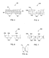
- FIG. 5 is a side view, partially cut-away of an alternate embodiment of the beam depicted in FIG. 4 ;
- FIGS. 6 and 7 are side views, partially cut-away of another alternate embodiment of the rail and yet another alternate embodiment of the rail depicted in FIG. 5 ;
- FIGS. 8-10 are cross-sectional views of the medical system depicted in FIGS. 1-3 , showing steps of operating the medical system;
- FIG. 11 is a plan view showing operation of the medical system depicted in FIGS. 1-3 .
- proximal and distal as used herein are intended to have a reference point relative to the user. Specifically, throughout the specification, the terms “distal” and “distally” shall denote a position, direction, or orientation that is generally away from the user, and the terms “proximal” and “proximally” shall denote a position, direction, or orientation that is generally towards the user.
- FIGS. 1-3 depict a medical system 20 for use intracorporeally to assist in surgical procedures beneath a tissue layer 10.
- the tissue layer 10 is typically that of a mammalian patient having a skin layer covering an bodily cavity 12 such as the abdominal or thoracic cavity having various organs 18 ( FIG. 11 ) therein.
- an bodily cavity 12 such as the abdominal or thoracic cavity having various organs 18 ( FIG. 11 ) therein.
- the medical system 20 generally includes a distal portion 22 intended to be utilized beneath the tissue 10 and within the body cavity 12, and a proximal portion 24 intended to reside above the tissue 10 and controlled by the medical professional or other user.
- the distal portion 22 of the medical system 20 generally includes a camera head 30 that is connected to a translating beam 50.
- the beam 50 slidably attaches through a guide sheath 70, part of which is also within the distal portion 22.
- the guide sheath 70 attaches to a handle 90 within the proximal portion 22 of the medical system 20, which -is utilized to orient and control translation of the beam 50 and camera head 30.
- the medical system 20 is generally intended to be used in conjunction with a port 14 positioned within an opening 13 ( FIG. 11 ) in the tissue 10.
- the port 14 has been depicted in FIG. 1 is a simple tubular member that is fitted within the opening 13, although various types of ports utilized in laparoscopic or other minimally invasive surgeries may be employed.
- One preferred port is that disclosed in US Appl. No. 61/564,021 filed November 28, 2011 entitled SURGICAL ACCESS PORT the contents of which are incorporated herein by reference in its entirety.
- the beam 50 is a one-way bending beam which can bend through the angles formed by the guide sheath 70 to allow the system 20 to rotate through the tissue 10 and extend generally in the plane of the tissue 10.
- the beam 50 resists bending in one direction and is oriented relative to the guide sheath such that, as the beam is slid relative to guide sheath, the beam bends in a first direction (generally down on the page in FIGS.
- the beam 50 is a cantilevered beam that is supported at the distal opening of the guide sheath 70.
- the beam 50 resistance to bending 'downward' under the force of gravity, assuming the system 20 and beam 50 are oriented appropriately relative to gravity, e.g. in most abdominal surgeries where the patient is in a supine or semi-supine position.
- the system 20 may be utilized when the patient is in other positions or the system 20 and beam 50 are rotated such that the plane of the first and second directions is not perfectly perpendicular to the ground.
- the apparatus 20, and in particular the handle 90 and guide sheath 70, may also be rotated relative to the port 14 such that the distal port 22 and its camera head 30 sweep through a plane generally parallel to the tissue 10.
- the beam 50 may be extended and retracted distally and proximally to position the camera head 30 within the cavity 12.
- the camera head 30 pivots relative to the beam 50, and preferably provides for both rotation about an axis 16 defined by the beam 50 as well as pivoting about an axis transverse to the axis of the beam 50. Accordingly, the medical system 20 provides 4 degrees of freedom to the camera head 34 for improved visualization and lighting throughout the body cavity 12.
- the camera head 30 generally includes a camera 32 and one or more lighting elements 34. Additional elements such as an electro cautery device 36 or injection ports may be provided within the camera head 30.
- the camera 32 is an HD camera which utilizes laparoscope camera technology having rod-lens imaging and "chip-in-the-tip" imaging. Utilizing rod-lenses, the images from the cameral 32 are captured on a sensor within the camera head 30 or within the handle 90.
- the lighting elements 34 are preferably LED elements and provide illumination via a electrical connection with the handle 90, or are lenses connected to a fiber optic cable carrying light from an external lamp, such as a Zenon arc lamp.
- the camera head 30 generally includes a joint member 38 connecting a distal head 40 to a proximal head portion 42.
- the joint 38 is pivotally connected to the proximal head portion 42, e.g. via a pin, ball-and-socket or other pivotal connection, to allow the joint 38 and the distal head portion 40 to pivot relative to the proximal head portion 42 and beam 50.
- the joint 38 also provides a flange 48 defining a surface about which the distal head portion 40 may rotate about the longitudinal axis of the joint 38 (and often axis 16 as shown).
- the pivoting and rotation of the camera head 30 may be accomplished via appropriately located control wires 44 which pass through an interior passageway 46 of the joint 38 and through the interior of the beam 50.
- the control wires 44 may mechanically transfer energy to the camera head 34 for articulation, or the camera head 30 may include small motors or prime movers (not shown) that are electrically driven via electric control wires 44.
- the beam 50 is generally formed by a plurality of links 52 connected on one side by a flexible strip 54.
- each of the links 52 preferably includes a bore 56 which is aligned with adjacent bores 56 to form an internal passageway through the beam 50 leading between the camera head 30 and the handle 90.
- One or more links 52 at the distal end of the beam 50 is attached to the proximal head portion 42 of the camera head 30.
- the links 52 may be formed of plastic or metal, while the strip 54 is formed of a resilient but flexible material, preferably of nitinol or other biocompatible metal or alloy, although sufficiently resilient plastics can also be used.
- the flexible strip 54 may be attached to the links 52 via an adhesive or using other bonding techniques such as fusion, soldering or welding at appropriate points to provide one-way bending.
- the strip 54 may include lateral slots, preferably at axial positions spaced from the abutting corners of the links, to provide a location for soldering or to control the stiffness and flexibility of the strip 54.
- the links may be attached to the strip 54a by bending small tabs 53a formed in the links, namely bending the tabs 53a through the lateral slots 55a and over the strip 54a thereby locking the links in place.
- the beam 50 does not flex more than 1 to 10 degrees from the straight linear axis 16 depicted in the figures. For example, in FIG.
- an alternate beam 150 (shown from the side) includes a plurality of links 152 which are connected to a plurality of small strips 154.
- the plurality of strips 154 are positioned to extend over the abutting corners 158 defining by the abutting surfaces 160 of adjacent links 152.
- the plurality of strips 154 are flexible such that the lower corners 162 (i.e. those down on the page in FIG. 5 ) may move away from each other while the links 152 general pivot about the other edges 158 which are held together via the strips 154.
- an alternate beam 250 includes a plurality of links 252 that are pivotally connected together at their upper adjacent corners via corresponding tabs and detents 254 which provide a hinge joint.
- FIG. 7 depicts an alternate beam 350 which includes a plurality of links 352 and each are pivotally attached at their upper corners to pins 354 which allow the links 352 to rotate relative to one another about the pins 354.
- the corners of the upper surfaces 356 are rounded (or chamfered, filleted, etc.) to accommodate the rotation, while the links include adjacent abutting surfaces 358 which extend below the pins 354 to prevent bending in the opposite direction (i.e. down on the page).
- the guide sheath 70 is tubular and generally includes a first sheath portion 72 and a second sheath portion 74.
- the first sheath portion is straight and defines a first axis (shown as coincident with axis 16 in FIG. 2 ), and likewise the second sheath portion 74 is generally straight and defines a second axis 75.
- the first sheath portion 72 is rotatable relative to the second sheath portion 74 about a hinge 76 to adjust the angle between the first and second axes.
- a control wire or other control member (not shown) is attached to the first sheath portion at a position distal to the hinge 76 to control articulation of the first sheath portion 72 between an introduction configuration and an operative configuration.
- the first sheath portion 72 In the introduction configuration ( FIG. 8 ) the first sheath portion 72 is generally aligned with the second sheath portion 74 such that the first axis and second axis are generally parallel.
- the first axis is rotated relative to the second axis, preferably between 1 and 135 degrees and most preferably around 90 degrees.
- FIG. 2 also shows that the first sheath portion 72 preferably includes plurality of projecting tabs 73 in an area of the hinge connection that are angularly spaced. The tabs 73 are sized and position engage the second sheath portion 74 (or are otherwise operatively connected thereto) to provide for discrete angular positioning of the first sheath portion 72 relative to the second sheath portion 74.
- a recess 78 is formed in the first sheath portion 72 and a corresponding recess (not shown) in the second sheath portion 74 provides an open space for the beam 50 to pass through a first bend 75 formed between the first and second sheath portions 72, 74.
- a third portion 80 of the guide sheath 70 (at a proximal end thereof) further defines a second bend 82.
- the second bend is fixed, such as by rigidly joining or unitarily forming the second and third sheath portions 74, 80, and is preferably around 90 degrees.
- the second bend could also be a controllable pivoting joint.
- the beam 50 rotates about 90 degrees through the second bend 82, and then rotates another 90 degrees through the first bend 75 such that a distal portion of the beam 50 extends generally parallel to a proximal portion of the beam 50 that is external to the tissue 10 (as with the distal and proximal portions 22, 24 of the system 20 described above).
- a proximal end 50 of the beam is attached to the handle 90.
- the handle 90 generally includes a housing 92 defining a guide rail 94, which has been depicted as a simple slot 94 formed longitudinally through the housing 92.
- a thumb slider 96 slides along the housing 92 guided by the slot 94, and includes a tab 98 projecting through the slot 94 and riding within the housing 92.
- the tab 98 is attached to the proximal end 58 of the beam 50, i.e. to one or more proximal links 52.
- the beam 50 may be moved distally and proximally through the guide sheath 70 and within the body cavity 12.
- the control wires 44 extending from the camera head 30 through the beam 50 also extend through the thumb slider 96 to various controls 100 located on thereon.
- the controls 100 may be operatively connected to a circuit board 102 or other electronic elements for transmitting and storing signals from the camera head 30, or may be attaching to winding wheels, torque wheels, tensioning mechanisms and the like for transmitting mechanical energy through the control wires 44 (e.g. for rotation of the camera 32).
- FIGS. 8-10 operation of the medical system 20 will be described.
- the medical system 20 is shown in the introduction configuration where the thumb slider 96 of the handle 90 is moved proximally (to the left on the page) to retract the beam 50.
- the beam 50 extends through the second bend 82 of the guide sheath 70 and through both the first and second sheath portions 72, 74 which are generally parallel.
- the angle of the second bend 82, the angle of the first bend 75 (which can be greater than zero in the introduction configuration), and the size of the first and second sheath portions 72, 74 are configured relative to one another to allow the distal portion 22 of the medical system 20 to pass through the opening in the port 14 (or directly through the opening 13 in tissue 10.
- the first sheath section 72 may be rotated relative to the second sheath portion 74 such that the guide sheath 70 forms the second bend 75, as shown in FIG. 9 .
- Rotation of the first sheath section 72 causes the distal end of the beam 50 to be rotated a total of about 180 degrees relative to the proximal portion residing in the handle 90. In this position, the entire handle assembly 90 may be rotated about a plane of the tissue 10 and the camera head 30 rotated or pivoted to initially identify the structures within the cavity 12.
- the beam 50 may be slid through the guide sheath and distally projected as shown in FIG. 10 .
- the beam 50 and camera head 30 project beyond a distal end of the guide sheath 70 and further into the cavity 12.
- additional instruments 125 may be passed through the port 14 or through other access points into the cavity 12 for performing surgery such as a laparoscopic or other minimally invasive surgery.
- the medical system 20 provides a means for introducing a distal section 22 of the device within the bodily cavity 12 while a proximal portion of the device 24 remains above the tissue 10 while the two portions 22, 24 are generally parallel to one another.
- This configuration is relatively unobtrusive to other instruments, and provides complete viewing of the cavity 12 by providing the camera 32 with 3 or 4 degrees of freedom.
- One of the advantages of the system 20 is that the camera 30 is moved away from the immediate vicinity of the operating field and other instruments, so that the instruments may be viewed from a side-view rather than head-on. This is likely to be an ideal perspective for operative visualization.
- the guide sheath 70 is generally depicted as performing a U-turn or bend in the operative configuration, it will be recognized that the pivotal connection between the first and second sheath portions 72, 74 can be such that the beam 50 is not coplanar with the handle 90 or the portion of the beam therein, or such that the beam 50 follows one or more bends that form an S-shape or Z-turn.
- the camera head 30 is provided with 4 degrees of freedom to find the best position within the cavity 12 to navigate around adjacent structures to illuminate and visualize an organ or other bodily structure 18 within the cavity 12, while still providing sufficient space for additional medical instruments 125 to be inserted through the opening 13 and the tissue 10 for operation on the same bodily structure 18.
- the articulation of the camera head 30 allows any degree of triangulation between the additional instruments and the camera head pointing towards the target. Accordingly, the medical system 20 is especially adapted for minimally invasive surgery which utilizes a single incision or single port.
- the camera head 30 includes side viewing camera 32, although it can also be provided at the distal end of the distal housing 40.
- control wires 44 need not extend through the beam 50, and could be provided alongside the exterior of the beam 50 such that the plurality of links 52 may be solid.
- the thumb slider 96 could be motorized, and further be electrically connected to a computer with proper software to control articulation of the slider 96 and translation of the beam 50, as well as both mechanical and electrical control over camera head 30 and receipt of its visual information.
- the systems, devices and methods may be used on any layer of material (e.g. fabrics, cloth, polymers, elastomers, plastics and rubber) that may or may not be associated with a human or animal body and a bodily lumen.
- the systems, devices and methods can find use in laboratory and industrial settings for placing devices through one or more layers of material that may or may not find application to the human or animal body, and likewise closing holes or perforations in layers of material that are not bodily tissue.
- Some examples include viewing behind structures such as walls, plates, floors, rubble (e.g. in rescue work), as well as working with synthetic tissues, polymeric sheets, animal studies, veterinary applications, and post-mortem activities.
Abstract
Description
- This application is a continuation-in-part of
US Appl. No. 12/896,373 filed October 1, 2010 - The present invention relates generally to medical devices and systems for use with laparoscopic procedures, and more particularly to apparatus for guiding medical instruments during such procedures.
- Traditional laparoscopic procedures involve the formation of puncture sites through the skin and related tissue layers to provide access to an internal structure within a bodily cavity. Upon formation of a puncture site, the natural elasticity of the tissue tends to close the opening, and thus a port is utilized to hold the site open. For example, a trocar port is device having a tubular configuration defining a port opening and having a configuration that engages the tissue to hold the site open.
- Multiple puncture sites, for example three or more, are provided in the desired area so that multiple instruments may be used for the particular laparoscopic procedure, as well as to allow for triangulation of the target structure. For example, a laparoscope or other visualization system may utilize one port, while a grasper or other tissue manipulator is used with the second port in conjunction with a cutting or suturing device utilized through the third port. While laparoscopic procedures are less invasive when compared to traditional open surgery, these procedures still leave multiple scars.
- One embodiment of a medical system, for use intracorporeally to assist in surgical procedures beneath a tissue layer, generally comprises a camera head, a beam, and a guide sheath. The camera head has a camera attached thereto, and the beam has a distal end attached to the camera head. The beam is bendable in a first direction and resists bending in a second direction opposite the first direction. The guide sheath slidably receives the beam, the beam extending through a distal end of the guide sheath such that the camera head projects from the distal end of the guide sheath. The guide sheath includes a first sheath portion defining a first axis and a second sheath portion defining a second axis, the guide sheath having an operative configuration wherein the first sheath portion is angled relative to the second sheath portion to define a first bend. The beam is oriented relative to the guide sheath such that, as the beam is slid relative to guide sheath, the beam bends in the first direction through the first bend, and a projecting portion of the beam projecting from the distal end of the guide sheath resists bending in the second direction. A port may optionally be provided as part of the system, and the components are sized such that the first sheath portion may pass through the port with the beam extending from a first side of the tissue layer to a second side of the tissue layer opposite the first side.
- According to more detailed aspects of this embodiment of the medical system, the beam sufficiently resists bending such that it does not bend under its own weight and the weight of the camera head. Preferably the beam sufficiently resists bending such that the projecting portion of the beam defines a beam axis extending linearly from the distal end of the guide sheath. The beam may be formed by a plurality of links connected together for relative rotation between adjacent links. In one variation, the links are connected by bendable strip on a first side of each link. In another variation, the links are hinged together at their ends, the ends defining an end surface that is structured to permit rotation of adjacent links relative to each other in the first direction, but restricts rotation of adjacent links towards each other in the second direction. The beam is preferably hollow to define a passageway extending to the distal end of the beam, and the system further includes one or more control wires extending through the passageway and operatively connected to the camera head.
- According to further detailed aspects of this embodiment of the medical system, the first bend is formed by the first sheath section being angled about 90 degrees relative to the second sheath section. The first sheath section is rotatably attached to the second sheath section. As such, the guide sheath has an introduction configuration wherein the first sheath section is generally parallel to the second sheath section. Preferably, the first sheath section is operable to rotate relative to the second sheath section over an arc spanning about 90 to about 180 degrees. The guide sheath may further include a third sheath section angled relative to second section to define a second bend. The second bend may be at a fixed angle, such as 90 degrees. Preferably, the first and second bend are oriented in the operative configuration to bend the beam over 180 degrees such that a proximal beam portion is about parallel to a distal beam portion.
- According to still further detailed aspects of this embodiment of the medical system, the camera head includes a proximal head portion fixed to the beam and a distal head portion rotatably attached to the proximal head portion. The distal head portion may rotate about a pivot axis such that the distal head portion is angled relative to the proximal head portion. Here, the pivot axis is perpendicular to a longitudinal axis of a projecting portion of the beam that projects from the guide sheath. The pivot axis may also be about parallel to a longitudinal axis of a projecting portion of the beam that projects from the guide sheath. In a preferred variation, the camera head further includes an intermediate head portion interconnecting the proximal and distal head portions, wherein the intermediate head portion is rotatable relative to one of the proximal and distal head portions about a first pivot axis such that the distal head portion is angled relative to the proximal head portion, and wherein the intermediate head portion is rotatable relative to other of the proximal and distal head portions about a second pivot axis that is about parallel to a longitudinal axis of a projecting portion of the beam that projects from the guide sheath.
- According to yet further detailed aspects of this embodiment of the medical system, the medical system may further comprise a handle attached to the guide sheath. The handle preferably includes a handle housing and a control slider slidably attached thereto, the control slider attached to the beam for translation of the beam through the guide sheath to position the camera head relative to the guide sheath. The handle is operatively connected to one or more control wires, such as a sheath control wire operatively connected to the first sheath section, one or more camera control wire extending through the passageway of the beam operatively connected to the camera head. The camera control wires may be mechanical, electrical and/or optical control wires for operation of the camera head. Any of these control wires preferably extend through the passageway of the beam
-
FIG. 1 is a perspective view of the medical system constructed in accordance with the teachings of the present invention; -
FIG. 2 is another perspective view, partially in cross-section, with the medical system depicted inFIG. 1 ; -
FIG. 3 is a cross-sectional view of the medical system depicted inFIG. 2 ; -
FIG. 4 is a cross-sectional view, partially cut-away or a beam forming a portion of the medical system depicted inFIGS. 1-3 ; -
FIG. 4a is a top view of an alternate of the beam ofFIG. 4 ; -
FIG. 5 is a side view, partially cut-away of an alternate embodiment of the beam depicted inFIG. 4 ; -
FIGS. 6 and 7 are side views, partially cut-away of another alternate embodiment of the rail and yet another alternate embodiment of the rail depicted inFIG. 5 ; -
FIGS. 8-10 are cross-sectional views of the medical system depicted inFIGS. 1-3 , showing steps of operating the medical system; -
FIG. 11 is a plan view showing operation of the medical system depicted inFIGS. 1-3 . - The terms "proximal" and "distal" as used herein are intended to have a reference point relative to the user. Specifically, throughout the specification, the terms "distal" and "distally" shall denote a position, direction, or orientation that is generally away from the user, and the terms "proximal" and "proximally" shall denote a position, direction, or orientation that is generally towards the user.
- Turning now to the figures,
FIGS. 1-3 depict amedical system 20 for use intracorporeally to assist in surgical procedures beneath atissue layer 10. Thetissue layer 10 is typically that of a mammalian patient having a skin layer covering anbodily cavity 12 such as the abdominal or thoracic cavity having various organs 18 (FIG. 11 ) therein. It will be readily apparent to those skilled in the art that themedical system 20 may be employed with many different bodily cavities and bodily structures, and is not limited to those described or depicted herein. Themedical system 20 generally includes adistal portion 22 intended to be utilized beneath thetissue 10 and within thebody cavity 12, and aproximal portion 24 intended to reside above thetissue 10 and controlled by the medical professional or other user. - In particular, the
distal portion 22 of themedical system 20 generally includes acamera head 30 that is connected to a translatingbeam 50. Thebeam 50 slidably attaches through aguide sheath 70, part of which is also within thedistal portion 22. Theguide sheath 70 attaches to ahandle 90 within theproximal portion 22 of themedical system 20, which -is utilized to orient and control translation of thebeam 50 andcamera head 30. Themedical system 20 is generally intended to be used in conjunction with aport 14 positioned within an opening 13 (FIG. 11 ) in thetissue 10. Theport 14 has been depicted inFIG. 1 is a simple tubular member that is fitted within theopening 13, although various types of ports utilized in laparoscopic or other minimally invasive surgeries may be employed. One preferred port is that disclosed inUS Appl. No. 61/564,021 filed November 28, 2011 - Through use of the
medical system 20 the entire area of thebodily cavity 12 may be visualized while additional medical instruments may be employed through theport 14 or through other access points to perform minimally invasive surgeries. As will be described in more detail herein, thebeam 50 is a one-way bending beam which can bend through the angles formed by theguide sheath 70 to allow thesystem 20 to rotate through thetissue 10 and extend generally in the plane of thetissue 10. Thebeam 50 resists bending in one direction and is oriented relative to the guide sheath such that, as the beam is slid relative to guide sheath, the beam bends in a first direction (generally down on the page inFIGS. 1-3 ) through the bends in theguide sheath 70, while a projecting portion of the beam (projecting from the distal end of the guide sheath) resists bending in a second direction opposite the first direction (generally up on the page inFIGS. 1-3 ). Stated another way, thebeam 50 is a cantilevered beam that is supported at the distal opening of theguide sheath 70. Thebeam 50 resistance to bending 'downward' under the force of gravity, assuming thesystem 20 andbeam 50 are oriented appropriately relative to gravity, e.g. in most abdominal surgeries where the patient is in a supine or semi-supine position. However, the skilled artisan will recognize that thesystem 20 may be utilized when the patient is in other positions or thesystem 20 andbeam 50 are rotated such that the plane of the first and second directions is not perfectly perpendicular to the ground. - The
apparatus 20, and in particular thehandle 90 and guidesheath 70, may also be rotated relative to theport 14 such that thedistal port 22 and itscamera head 30 sweep through a plane generally parallel to thetissue 10. Further, thebeam 50 may be extended and retracted distally and proximally to position thecamera head 30 within thecavity 12. Additionally, thecamera head 30 pivots relative to thebeam 50, and preferably provides for both rotation about anaxis 16 defined by thebeam 50 as well as pivoting about an axis transverse to the axis of thebeam 50. Accordingly, themedical system 20 provides 4 degrees of freedom to thecamera head 34 for improved visualization and lighting throughout thebody cavity 12. - Turning now to
FIG. 2 , thecamera head 30 generally includes acamera 32 and one ormore lighting elements 34. Additional elements such as anelectro cautery device 36 or injection ports may be provided within thecamera head 30. Preferably, thecamera 32 is an HD camera which utilizes laparoscope camera technology having rod-lens imaging and "chip-in-the-tip" imaging. Utilizing rod-lenses, the images from the cameral 32 are captured on a sensor within thecamera head 30 or within thehandle 90. Thelighting elements 34 are preferably LED elements and provide illumination via a electrical connection with thehandle 90, or are lenses connected to a fiber optic cable carrying light from an external lamp, such as a Zenon arc lamp. - The
camera head 30 generally includes ajoint member 38 connecting adistal head 40 to aproximal head portion 42. The joint 38 is pivotally connected to theproximal head portion 42, e.g. via a pin, ball-and-socket or other pivotal connection, to allow the joint 38 and thedistal head portion 40 to pivot relative to theproximal head portion 42 andbeam 50. The joint 38 also provides aflange 48 defining a surface about which thedistal head portion 40 may rotate about the longitudinal axis of the joint 38 (and oftenaxis 16 as shown). The pivoting and rotation of thecamera head 30 may be accomplished via appropriately locatedcontrol wires 44 which pass through aninterior passageway 46 of the joint 38 and through the interior of thebeam 50. Thecontrol wires 44 may mechanically transfer energy to thecamera head 34 for articulation, or thecamera head 30 may include small motors or prime movers (not shown) that are electrically driven viaelectric control wires 44. - As also shown in
FIGS. 2 and3 , thebeam 50 is generally formed by a plurality oflinks 52 connected on one side by aflexible strip 54. As best seen inFIG. 4 , each of thelinks 52 preferably includes abore 56 which is aligned withadjacent bores 56 to form an internal passageway through thebeam 50 leading between thecamera head 30 and thehandle 90. One ormore links 52 at the distal end of thebeam 50 is attached to theproximal head portion 42 of thecamera head 30. Thelinks 52 may be formed of plastic or metal, while thestrip 54 is formed of a resilient but flexible material, preferably of nitinol or other biocompatible metal or alloy, although sufficiently resilient plastics can also be used. Theflexible strip 54 may be attached to thelinks 52 via an adhesive or using other bonding techniques such as fusion, soldering or welding at appropriate points to provide one-way bending. For example, thestrip 54 may include lateral slots, preferably at axial positions spaced from the abutting corners of the links, to provide a location for soldering or to control the stiffness and flexibility of thestrip 54. Likewise, as shown inFIG. 4a , the links may be attached to thestrip 54a by bending small tabs 53a formed in the links, namely bending the tabs 53a through the lateral slots 55a and over thestrip 54a thereby locking the links in place. - It will be recognized by the skilled artisan, in view of this disclosure, that other variations of the
beam 50 are possible to provide for a one-way bending beam which allows bending in a first direction (i.e. towards one side of the beam) so that it may pass through the bends formed in theguide sheath 70 as shown inFIGS. 2 and3 , while resisting bending in a second direction opposite the first direction so that thebeam 50 may be extended distally from theguide sheath 70 as also shown inFIGS. 2 and3 . Preferably, thebeam 50 does not flex more than 1 to 10 degrees from the straightlinear axis 16 depicted in the figures. For example, inFIG. 5 an alternate beam 150 (shown from the side) includes a plurality oflinks 152 which are connected to a plurality ofsmall strips 154. The plurality ofstrips 154 are positioned to extend over the abuttingcorners 158 defining by the abuttingsurfaces 160 ofadjacent links 152. As in the prior embodiment, the plurality ofstrips 154 are flexible such that the lower corners 162 (i.e. those down on the page inFIG. 5 ) may move away from each other while thelinks 152 general pivot about theother edges 158 which are held together via thestrips 154. - In
FIG. 6 , analternate beam 250 includes a plurality oflinks 252 that are pivotally connected together at their upper adjacent corners via corresponding tabs anddetents 254 which provide a hinge joint. Similarly,FIG. 7 depicts analternate beam 350 which includes a plurality oflinks 352 and each are pivotally attached at their upper corners topins 354 which allow thelinks 352 to rotate relative to one another about thepins 354. Here the corners of theupper surfaces 356 are rounded (or chamfered, filleted, etc.) to accommodate the rotation, while the links include adjacent abuttingsurfaces 358 which extend below thepins 354 to prevent bending in the opposite direction (i.e. down on the page). - Turning back to
FIG. 2 , theguide sheath 70 is tubular and generally includes afirst sheath portion 72 and asecond sheath portion 74. The first sheath portion is straight and defines a first axis (shown as coincident withaxis 16 inFIG. 2 ), and likewise thesecond sheath portion 74 is generally straight and defines asecond axis 75. Thefirst sheath portion 72 is rotatable relative to thesecond sheath portion 74 about ahinge 76 to adjust the angle between the first and second axes. A control wire or other control member (not shown) is attached to the first sheath portion at a position distal to thehinge 76 to control articulation of thefirst sheath portion 72 between an introduction configuration and an operative configuration. In the introduction configuration (FIG. 8 ) thefirst sheath portion 72 is generally aligned with thesecond sheath portion 74 such that the first axis and second axis are generally parallel. In the operative configuration (FIGS. 2 ,3 ,9 ) the first axis is rotated relative to the second axis, preferably between 1 and 135 degrees and most preferably around 90 degrees.FIG. 2 also shows that thefirst sheath portion 72 preferably includes plurality of projectingtabs 73 in an area of the hinge connection that are angularly spaced. Thetabs 73 are sized and position engage the second sheath portion 74 (or are otherwise operatively connected thereto) to provide for discrete angular positioning of thefirst sheath portion 72 relative to thesecond sheath portion 74. - In the operative configuration shown in
FIG. 2 , it can be seen that arecess 78 is formed in thefirst sheath portion 72 and a corresponding recess (not shown) in thesecond sheath portion 74 provides an open space for thebeam 50 to pass through afirst bend 75 formed between the first andsecond sheath portions third portion 80 of the guide sheath 70 (at a proximal end thereof) further defines asecond bend 82. The second bend is fixed, such as by rigidly joining or unitarily forming the second andthird sheath portions - Accordingly, in the operative configuration shown in
FIGS. 2 and3 , thebeam 50 rotates about 90 degrees through thesecond bend 82, and then rotates another 90 degrees through thefirst bend 75 such that a distal portion of thebeam 50 extends generally parallel to a proximal portion of thebeam 50 that is external to the tissue 10 (as with the distal andproximal portions system 20 described above). - As also seen in
FIGS. 2-3 , aproximal end 50 of the beam is attached to thehandle 90. As best seen inFIG. 3 , thehandle 90 generally includes ahousing 92 defining aguide rail 94, which has been depicted as asimple slot 94 formed longitudinally through thehousing 92. Athumb slider 96 slides along thehousing 92 guided by theslot 94, and includes atab 98 projecting through theslot 94 and riding within thehousing 92. Thetab 98 is attached to theproximal end 58 of thebeam 50, i.e. to one or moreproximal links 52. Through translation of thethumb slider 96, thebeam 50 may be moved distally and proximally through theguide sheath 70 and within thebody cavity 12. Thecontrol wires 44 extending from thecamera head 30 through thebeam 50 also extend through thethumb slider 96 tovarious controls 100 located on thereon. Thecontrols 100 may be operatively connected to acircuit board 102 or other electronic elements for transmitting and storing signals from thecamera head 30, or may be attaching to winding wheels, torque wheels, tensioning mechanisms and the like for transmitting mechanical energy through the control wires 44 (e.g. for rotation of the camera 32). - Turning now to
FIGS. 8-10 , operation of themedical system 20 will be described. InFIG. 8 themedical system 20 is shown in the introduction configuration where thethumb slider 96 of thehandle 90 is moved proximally (to the left on the page) to retract thebeam 50. Thebeam 50 extends through thesecond bend 82 of theguide sheath 70 and through both the first andsecond sheath portions second bend 82, the angle of the first bend 75 (which can be greater than zero in the introduction configuration), and the size of the first andsecond sheath portions distal portion 22 of themedical system 20 to pass through the opening in the port 14 (or directly through theopening 13 intissue 10. - After the
camera head 30 andfirst sheath portion 72 are passed through the port 14 (or otherwise through the tissue 10), thefirst sheath section 72 may be rotated relative to thesecond sheath portion 74 such that theguide sheath 70 forms thesecond bend 75, as shown inFIG. 9 . Rotation of thefirst sheath section 72 causes the distal end of thebeam 50 to be rotated a total of about 180 degrees relative to the proximal portion residing in thehandle 90. In this position, theentire handle assembly 90 may be rotated about a plane of thetissue 10 and thecamera head 30 rotated or pivoted to initially identify the structures within thecavity 12. - Through translation of the
thumb 96 relative to thehousing 92 of thehandle 90, thebeam 50 may be slid through the guide sheath and distally projected as shown inFIG. 10 . Thebeam 50 andcamera head 30 project beyond a distal end of theguide sheath 70 and further into thecavity 12. As shown inFIG. 11 , upon securing ideal lighting and visualization of the target within thecavity 12,additional instruments 125 may be passed through theport 14 or through other access points into thecavity 12 for performing surgery such as a laparoscopic or other minimally invasive surgery. Accordingly, it can be seen that themedical system 20 provides a means for introducing adistal section 22 of the device within thebodily cavity 12 while a proximal portion of thedevice 24 remains above thetissue 10 while the twoportions cavity 12 by providing thecamera 32 with 3 or 4 degrees of freedom. One of the advantages of thesystem 20 is that thecamera 30 is moved away from the immediate vicinity of the operating field and other instruments, so that the instruments may be viewed from a side-view rather than head-on. This is likely to be an ideal perspective for operative visualization. - While the
guide sheath 70 is generally depicted as performing a U-turn or bend in the operative configuration, it will be recognized that the pivotal connection between the first andsecond sheath portions beam 50 is not coplanar with thehandle 90 or the portion of the beam therein, or such that thebeam 50 follows one or more bends that form an S-shape or Z-turn. In the operative configuration depicted inFIG. 11 , thecamera head 30 is provided with 4 degrees of freedom to find the best position within thecavity 12 to navigate around adjacent structures to illuminate and visualize an organ or otherbodily structure 18 within thecavity 12, while still providing sufficient space for additionalmedical instruments 125 to be inserted through theopening 13 and thetissue 10 for operation on the samebodily structure 18. The articulation of thecamera head 30 allows any degree of triangulation between the additional instruments and the camera head pointing towards the target. Accordingly, themedical system 20 is especially adapted for minimally invasive surgery which utilizes a single incision or single port. - Preferably, the
camera head 30 includesside viewing camera 32, although it can also be provided at the distal end of thedistal housing 40. It will also be recognized thatcontrol wires 44 need not extend through thebeam 50, and could be provided alongside the exterior of thebeam 50 such that the plurality oflinks 52 may be solid. In some embodiments, thethumb slider 96 could be motorized, and further be electrically connected to a computer with proper software to control articulation of theslider 96 and translation of thebeam 50, as well as both mechanical and electrical control overcamera head 30 and receipt of its visual information. - It will also be recognized by those skilled in the art that, while the methods described above generally include passing through tissue and into an internal bodily cavity or lumen, it will be recognized that the systems, devices and methods may be used on any layer of material (e.g. fabrics, cloth, polymers, elastomers, plastics and rubber) that may or may not be associated with a human or animal body and a bodily lumen. For example, the systems, devices and methods can find use in laboratory and industrial settings for placing devices through one or more layers of material that may or may not find application to the human or animal body, and likewise closing holes or perforations in layers of material that are not bodily tissue. Some examples include viewing behind structures such as walls, plates, floors, rubble (e.g. in rescue work), as well as working with synthetic tissues, polymeric sheets, animal studies, veterinary applications, and post-mortem activities.
- The foregoing description of various embodiments of the invention has been presented for purposes of illustration and description. It is not intended to be exhaustive or to limit the invention to the precise embodiments disclosed. Numerous modifications or variations are possible in light of the above teachings. The embodiments discussed were chosen and described to provide the best illustration of the principles of the invention and its practical application to thereby enable one of ordinary skill in the art to utilize the invention in various embodiments and with various modifications as are suited to the particular use contemplated. All such modifications and variations are within the scope of the invention as determined by the appended claims when interpreted in accordance with the breadth to which they are fairly, legally, and equitably entitled.
Claims (20)
- A medical system for use intracorporeally to assist in surgical procedures beneath a tissue layer, the system comprising:a camera;a beam having a distal end attached to the camera, the beam bendable in a first direction and resisting bending in a second direction opposite the first direction;a guide sheath slidably receiving the beam, the beam extending through a distal end of the guide sheath such that the camera projects from the distal end of the guide sheath, the guide sheath including a first sheath portion defining a first axis and a second sheath portion defining a second axis, the guide sheath having an operative configuration wherein the first sheath portion is angled relative to the second sheath portion to define a first bend; andthe beam oriented relative to the guide sheath such that, as the beam is slid relative to guide sheath, the beam bends in the first direction through the first bend, and a projecting portion of the beam projecting from the distal end of the guide sheath resists bending in the second direction.
- The medical system of claim 1, wherein the beam sufficiently resists bending such that it does not bend under its own weight and the weight of the camera.
- The medical system of claim 1, wherein the beam sufficiently resists bending such that the projecting portion of the beam defines a beam axis extending linearly from the distal end of the guide sheath.
- The medical system of claim 1, wherein the beam is formed by a plurality of links connected together for relative rotation between adjacent links.
- The medical system of claim 4, wherein the links are connected by bendable strip on a first side of each link.
- The medical system of claim 4, wherein the links are hinged together at their ends, the ends defining an end surface that is structured to permit rotation of adjacent links relative to each other in the first direction, but restricts rotation of adjacent links towards each other in the second direction
- The medical system of claim 4, wherein the end surfaces define chamfers with a first side surface located towards the first direction.
- The medical system of claim 1, wherein the beam is hollow to define a passageway extending to the distal end of the beam, and further comprising a control wire extending through the passageway and operatively connected to the camera.
- The medical system of claim 1, wherein the first bend is formed by the first sheath section being angled about 90 degrees relative to the second sheath section.
- The medical system of claim 1, wherein the first sheath section is rotatably attached to the second sheath section.
- The medical system of claim 10, wherein the guide sheath has an introduction configuration wherein the first sheath section is generally parallel to the second sheath section.
- The medical system of claim 1, wherein the first sheath section is operable to rotate relative to the second sheath section over an arc spanning about 90 to about 135 degrees.
- The medical system of claim 1, further comprising a third sheath section angled relative to second section to define a second bend.
- The medical system of claim 13, wherein the second bend is at a fixed angle.
- The medical system of claim 13, wherein the first and second bend are oriented in the operative configuration to bend the beam over 180 degrees such that a proximal beam portion is about parallel to a distal beam portion.
- The medical system of claim 1, further comprising a camera head supporting the camera and attached to the distal end of the beam, wherein the camera head includes a proximal head portion fixed to the beam and a distal head portion rotatably attached to the proximal head portion.
- The medical system of claim 16, wherein the distal head portion rotates about a pivot axis such that the distal head portion is angled relative to the proximal head portion.
- The medical system of claim 17, wherein the pivot axis is perpendicular to a longitudinal axis of a projecting portion of the beam that projects from the guide sheath.
- The medical system of claim 16, wherein the distal head portion rotates about a pivot axis, the pivot axis about parallel to a longitudinal axis of a projecting portion of the beam that projects from the guide sheath.
- The medical system of claim 19, further comprising an intermediate head portion interconnecting the proximal and distal head portions, wherein the intermediate head portion is rotatable relative to one of the proximal and distal head portions about a first pivot axis such that the distal head portion is angled relative to the proximal head portion, and wherein the intermediate head portion is rotatable relative to other of the proximal and distal head portions about a second pivot axis that is about parallel to a longitudinal axis of a projecting portion of the beam that projects from the guide sheath.
Applications Claiming Priority (1)
| Application Number | Priority Date | Filing Date | Title |
|---|---|---|---|
| US13/408,640 US9339264B2 (en) | 2010-10-01 | 2012-02-29 | Port access visualization platform |
Publications (2)
| Publication Number | Publication Date |
|---|---|
| EP2633799A1 true EP2633799A1 (en) | 2013-09-04 |
| EP2633799B1 EP2633799B1 (en) | 2014-11-05 |
Family
ID=46637401
Family Applications (1)
| Application Number | Title | Priority Date | Filing Date |
|---|---|---|---|
| EP13155705.0A Active EP2633799B1 (en) | 2012-02-29 | 2013-02-19 | Port access visualization platform |
Country Status (4)
| Country | Link |
|---|---|
| US (2) | US9339264B2 (en) |
| EP (1) | EP2633799B1 (en) |
| JP (1) | JP5666638B2 (en) |
| AU (1) | AU2013201155B2 (en) |
Cited By (2)
| Publication number | Priority date | Publication date | Assignee | Title |
|---|---|---|---|---|
| CN104939800A (en) * | 2015-06-16 | 2015-09-30 | 山东省肿瘤防治研究院 | Gastrointestinal automatic detection surgical instrument |
| US10076239B2 (en) | 2009-10-02 | 2018-09-18 | Cook Medical Technologies Llc | Port access visualization platform |
Families Citing this family (15)
| Publication number | Priority date | Publication date | Assignee | Title |
|---|---|---|---|---|
| US8888792B2 (en) | 2008-07-14 | 2014-11-18 | Ethicon Endo-Surgery, Inc. | Tissue apposition clip application devices and methods |
| US20110082370A1 (en) * | 2009-10-02 | 2011-04-07 | Wilson-Cook Medical Inc. | Endoscopic fascia tunneling |
| US9427255B2 (en) | 2012-05-14 | 2016-08-30 | Ethicon Endo-Surgery, Inc. | Apparatus for introducing a steerable camera assembly into a patient |
| US10098527B2 (en) * | 2013-02-27 | 2018-10-16 | Ethidcon Endo-Surgery, Inc. | System for performing a minimally invasive surgical procedure |
| DE102013211698B4 (en) * | 2013-06-20 | 2017-07-06 | Fraunhofer-Gesellschaft zur Förderung der angewandten Forschung e.V. | Endoabdominal camera system |
| US10849483B2 (en) | 2014-09-15 | 2020-12-01 | Vivid Medical, Inc. | Single-use, port deployable articulating endoscope |
| US10850046B2 (en) * | 2016-03-28 | 2020-12-01 | Becton, Dickinson And Company | Cannula locator device |
| EP3827770A4 (en) * | 2018-05-09 | 2022-08-24 | Arroyo Tristan, Andres del Amor | Endoscope video camera head which can be attached to a surgical wound protector, without a rigid tube or manual support |
| ES2730387B2 (en) * | 2018-05-09 | 2020-10-01 | Tristan Andres Del Amor Arroyo | ENDOSCOPIC CAMERA HEAD ATTACHED TO SURGICAL WOUND PROTECTOR, WITHOUT RIGID TUBE OR MANUAL RESTRAINT |
| JP7256848B2 (en) * | 2019-04-04 | 2023-04-12 | グリー株式会社 | Program, control method and computer |
| EP4099009A4 (en) * | 2020-01-30 | 2023-08-30 | Mitsubishi Heavy Industries, Ltd. | Non-destructive inspection device and non-destructive inspection method |
| DE102020132776A1 (en) * | 2020-12-09 | 2022-06-09 | Karl Storz Se & Co. Kg | Hybrid endoscope with rotating drum for sterile medical applications |
| EP4066770A1 (en) * | 2021-04-02 | 2022-10-05 | Robeaute | Delivery and gathering system comprising a microrobot |
| KR20230119150A (en) * | 2020-12-16 | 2023-08-16 | 로보테 | Delivery and collection system including microrobot |
| US20220395171A1 (en) * | 2021-06-15 | 2022-12-15 | Arthrex, Inc. | Surgical camera system |
Citations (5)
| Publication number | Priority date | Publication date | Assignee | Title |
|---|---|---|---|---|
| US20090062604A1 (en) * | 2006-02-27 | 2009-03-05 | Ryo Minosawa | Endoscopic surgery tool |
| US20090082723A1 (en) * | 2005-11-17 | 2009-03-26 | Magnus Krogh | Medical devices and methods for their fabrication and use |
| US20110082345A1 (en) * | 2009-10-02 | 2011-04-07 | Wilson-Cook Medical Inc. | Apparatus for single port access |
| US20110207999A1 (en) * | 2010-02-24 | 2011-08-25 | Nobuyuki Torisawa | Torque transmission device having control wire |
| US20110251519A1 (en) * | 2010-04-09 | 2011-10-13 | Alexandre Romoscanu | Variable stiffness steering mechanism for catheters |
Family Cites Families (160)
| Publication number | Priority date | Publication date | Assignee | Title |
|---|---|---|---|---|
| US11025A (en) * | 1854-06-06 | litta | ||
| US3677262A (en) | 1970-07-23 | 1972-07-18 | Henry J Zukowski | Surgical instrument illuminating endotracheal tube inserter |
| US3690775A (en) * | 1971-09-01 | 1972-09-12 | Avco Corp | Borescope fixture |
| US3778170A (en) * | 1972-11-02 | 1973-12-11 | Gen Electric | Borescope guide tube |
| US3858577A (en) | 1974-04-05 | 1975-01-07 | Univ Southern California | Fiber optic laser light delivery system |
| JPS5552747A (en) | 1978-10-12 | 1980-04-17 | Tokyo Ika Shika Daigakuchiyou | Medical appliance holding instrument |
| US4222382A (en) * | 1979-01-26 | 1980-09-16 | Massachusetts Institute Of Technology | Femoral component hip joint prosthesis extractor |
| US4254763A (en) | 1979-06-07 | 1981-03-10 | Codman & Shurtleff, Inc. | Surgical retractor assembly |
| GB2147210B (en) | 1983-09-28 | 1986-12-17 | Wolf Gmbh Richard | An endoscope |
| US4640124A (en) * | 1984-02-16 | 1987-02-03 | Richard Wolf Gmbh | Tecnoscopes |
| US4640273A (en) | 1985-05-08 | 1987-02-03 | E-Z-Em, Inc. | Mouth guard for use with a diagnostic instrument |
| JPH0546406Y2 (en) * | 1988-07-20 | 1993-12-06 | ||
| US4911148A (en) * | 1989-03-14 | 1990-03-27 | Intramed Laboratories, Inc. | Deflectable-end endoscope with detachable flexible shaft assembly |
| US5643221A (en) * | 1990-05-04 | 1997-07-01 | Bullard; James Roger | Controlled targeting laryngoscope |
| US5133336A (en) * | 1990-10-22 | 1992-07-28 | Endoscopy Support Services, Inc. | Disposable liquid supply system for use in an endoscope |
| US5716327A (en) | 1991-05-29 | 1998-02-10 | Origin Medsystems, Inc. | Body wall retraction system for wide cavity retraction |
| MX9202604A (en) | 1991-05-29 | 1994-05-31 | Origin Medsystems Inc | APPARATUS FOR MECHANICAL PROPERTY RETRACTION AND METHODS OF USE. |
| US5571215A (en) | 1993-02-22 | 1996-11-05 | Heartport, Inc. | Devices and methods for intracardiac procedures |
| JPH05123287A (en) * | 1991-11-08 | 1993-05-21 | Olympus Optical Co Ltd | Protective sheath |
| JP3147318B2 (en) * | 1992-08-26 | 2001-03-19 | オリンパス光学工業株式会社 | Forward scan type internal ultrasound probe |
| US5469853A (en) | 1992-12-11 | 1995-11-28 | Tetrad Corporation | Bendable ultrasonic probe and sheath for use therewith |
| US5547458A (en) | 1994-07-11 | 1996-08-20 | Ethicon, Inc. | T-shaped abdominal wall lift with telescoping member |
| US5522788A (en) * | 1994-10-26 | 1996-06-04 | Kuzmak; Lubomyr I. | Finger-like laparoscopic blunt dissector device |
| US5512035A (en) * | 1994-10-27 | 1996-04-30 | Circon Corporation, A Delaware Corporation | Cable compensating mechanism for an endoscope |
| US5749889A (en) | 1996-02-13 | 1998-05-12 | Imagyn Medical, Inc. | Method and apparatus for performing biopsy |
| CA2197614C (en) | 1996-02-20 | 2002-07-02 | Charles S. Taylor | Surgical instruments and procedures for stabilizing the beating heart during coronary artery bypass graft surgery |
| US6196968B1 (en) * | 1997-06-02 | 2001-03-06 | General Surgical Innovations, Inc. | Direct vision subcutaneous tissue retractor and method for use |
| US5913818A (en) | 1997-06-02 | 1999-06-22 | General Surgical Innovations, Inc. | Vascular retractor |
| JP4121615B2 (en) | 1997-10-31 | 2008-07-23 | オリンパス株式会社 | Endoscope |
| US5976075A (en) * | 1997-12-15 | 1999-11-02 | University Of Massachusetts | Endoscope deployment apparatus |
| DE19906191A1 (en) | 1999-02-15 | 2000-08-17 | Ingo F Herrmann | Mouldable endoscope for transmitting light and images with supplementary device has non-round cross section along longitudinal section for inserting in human or animal body opening |
| CA2286929A1 (en) | 1999-10-18 | 2001-04-18 | Anthony Paolitto | Valve surgery apparatus |
| US6530929B1 (en) | 1999-10-20 | 2003-03-11 | Sdgi Holdings, Inc. | Instruments for stabilization of bony structures |
| US6416469B1 (en) | 2000-01-26 | 2002-07-09 | Genzyme Corporation | Suture organizing and retaining device and base member for surgical retractor |
| US6235028B1 (en) | 2000-02-14 | 2001-05-22 | Sdgi Holdings, Inc. | Surgical guide rod |
| US6539942B2 (en) * | 2001-04-19 | 2003-04-01 | Richard Schwartz | Endotracheal intubation device |
| US6528908B1 (en) * | 2001-10-09 | 2003-03-04 | Rick Lee | Induction drive for induction driven conveyor including a virtual continuous magnetic body and method of driving induction driven conveyor including a virtual continuous magnetic body |
| JP2007525242A (en) | 2003-04-25 | 2007-09-06 | タイコ ヘルスケア グループ エルピー | Surgical access device |
| US7431694B2 (en) | 2003-05-16 | 2008-10-07 | Ethicon Endo-Surgery, Inc. | Method of guiding medical devices |
| US7815565B2 (en) | 2003-05-16 | 2010-10-19 | Ethicon Endo-Surgery, Inc. | Endcap for use with an endoscope |
| US7615003B2 (en) | 2005-05-13 | 2009-11-10 | Ethicon Endo-Surgery, Inc. | Track for medical devices |
| JP3521910B1 (en) | 2003-05-29 | 2004-04-26 | 清輝 司馬 | External forceps channel device for endoscope |
| US7753901B2 (en) | 2004-07-21 | 2010-07-13 | Tyco Healthcare Group Lp | Laparoscopic instrument and cannula assembly and related surgical method |
| US7717847B2 (en) | 2004-04-05 | 2010-05-18 | Tyco Healthcare Group Lp | Surgical hand access apparatus |
| US20070167682A1 (en) * | 2004-04-21 | 2007-07-19 | Acclarent, Inc. | Endoscopic methods and devices for transnasal procedures |
| US7658738B2 (en) | 2004-05-14 | 2010-02-09 | Ethicon Endo-Surgery, Inc. | Medical devices for use with endoscope |
| US8328810B2 (en) | 2004-06-17 | 2012-12-11 | Boston Scientific Scimed, Inc. | Slidable sheaths for tissue removal devices |
| JP4980899B2 (en) * | 2004-06-25 | 2012-07-18 | カーネギー メロン ユニバーシティ | Steerable follow-the-reader device |
| JP4302602B2 (en) | 2004-09-24 | 2009-07-29 | オリンパス株式会社 | Endoscopic treatment tool, endoscopic treatment system, and support adapter |
| US7963976B2 (en) * | 2004-11-04 | 2011-06-21 | Dynamic Surgical Inventions, Llc | Articulated surgical probe and method for use |
| FR2879914B1 (en) | 2004-12-24 | 2007-03-09 | Protomed Sarl | INTESTINAL RETRACTOR RETRACTOR FOR COELIOSCOPIC SURGERY |
| JP4477519B2 (en) | 2005-02-14 | 2010-06-09 | オリンパス株式会社 | Endoscope |
| US7766810B2 (en) | 2005-03-10 | 2010-08-03 | Olympus Medical Systems Corp. | Probing method and holding method for luminal organ |
| US7717878B2 (en) | 2005-04-25 | 2010-05-18 | Tyco Healthcare Group Lp | Surgical portal with seal system |
| WO2007011689A2 (en) | 2005-07-15 | 2007-01-25 | The Brigham And Women's Hospital, Inc. | Sterile access conduit |
| EP1759629B1 (en) * | 2005-08-31 | 2014-04-02 | Karl Storz GmbH & Co. KG | Endoscope with variable direction of view |
| US7520879B2 (en) | 2006-02-07 | 2009-04-21 | Warsaw Orthopedic, Inc. | Surgical instruments and techniques for percutaneous placement of spinal stabilization elements |
| US20070213754A1 (en) | 2006-03-08 | 2007-09-13 | Olympus Medical Systems Corp. | Incision instrument, incision apparatus, and organ incision method |
| US8961406B2 (en) | 2009-03-06 | 2015-02-24 | Ethicon Endo-Surgery, Inc. | Surgical access devices and methods providing seal movement in predefined movement regions |
| US8425410B2 (en) | 2008-09-30 | 2013-04-23 | Ethicon Endo-Surgery, Inc. | Surgical access device with protective element |
| US8926506B2 (en) | 2009-03-06 | 2015-01-06 | Ethicon Endo-Surgery, Inc. | Methods and devices for providing access into a body cavity |
| US20100228096A1 (en) | 2009-03-06 | 2010-09-09 | Ethicon Endo-Surgery, Inc. | Methods and devices for providing access into a body cavity |
| US20100081883A1 (en) | 2008-09-30 | 2010-04-01 | Ethicon Endo-Surgery, Inc. | Methods and devices for performing gastroplasties using a multiple port access device |
| US8430811B2 (en) | 2008-09-30 | 2013-04-30 | Ethicon Endo-Surgery, Inc. | Multiple port surgical access device |
| US8485970B2 (en) | 2008-09-30 | 2013-07-16 | Ethicon Endo-Surgery, Inc. | Surgical access device |
| US20100081864A1 (en) | 2008-09-30 | 2010-04-01 | Ethicon Endo-Surgery, Inc. | Methods and devices for performing gastrectomies and gastroplasties |
| US8206294B2 (en) | 2008-09-30 | 2012-06-26 | Ethicon Endo-Surgery, Inc. | Surgical access device with flexible seal channel |
| US8821391B2 (en) | 2009-03-06 | 2014-09-02 | Ethicon Endo-Surgery, Inc. | Methods and devices for providing access into a body cavity |
| US8251900B2 (en) | 2009-03-06 | 2012-08-28 | Ethicon Endo-Surgery, Inc. | Surgical access devices and methods providing seal movement in predefined paths |
| US8357085B2 (en) | 2009-03-31 | 2013-01-22 | Ethicon Endo-Surgery, Inc. | Devices and methods for providing access into a body cavity |
| DE102006016845B3 (en) * | 2006-04-07 | 2007-08-30 | Olympus Winter & Ibe Gmbh | Medical endoscope has shaft, and main part and end part are surrounded in sealed manner by rigid shaft tube, which are sealed at hinge with hollow axle that is perpendicular to longitudinal axis of shaft parts and supported together |
| US20070244362A1 (en) * | 2006-04-12 | 2007-10-18 | Roger El-Hachem | Segmented colonoscope |
| EP2012697A4 (en) | 2006-04-29 | 2010-07-21 | Univ Texas | Devices for use in transluminal and endoluminal surgery |
| US7841980B2 (en) | 2006-05-11 | 2010-11-30 | Olympus Medical Systems Corp. | Treatment system, trocar, treatment method and calibration method |
| AU2007269043A1 (en) | 2006-07-07 | 2008-01-10 | Alan Kessler | Channeled flexible sleeve for medical articles |
| DE102006000399A1 (en) * | 2006-08-10 | 2008-02-14 | Novineon Healthcare Technology Partners Gmbh | Medical instrument |
| JP5226197B2 (en) * | 2006-08-25 | 2013-07-03 | オリンパス株式会社 | Endoscope guide tube and endoscope apparatus |
| US7806870B2 (en) | 2006-10-06 | 2010-10-05 | Surgiquest, Incorporated | Elastically deformable surgical access device having telescoping guide tube |
| US7798998B2 (en) | 2006-10-06 | 2010-09-21 | Surgiquest, Inc. | Elastically deformable surgical access device |
| US7976458B2 (en) * | 2006-12-05 | 2011-07-12 | Ethicon Endo-Surgery, Inc. | Independent articulating accessory channel |
| US20080208001A1 (en) * | 2007-02-26 | 2008-08-28 | Ron Hadani | Conforming endoscope |
| US20100261962A1 (en) | 2007-03-21 | 2010-10-14 | Friedberg Joseph S | Natural orifice transluminal endoscopic surgery overtube and method of introducing multiple endoscopes |
| JP5021346B2 (en) * | 2007-03-23 | 2012-09-05 | オリンパス株式会社 | Endoscope guide tube and endoscope apparatus |
| US8353819B2 (en) | 2007-04-11 | 2013-01-15 | Covidien Lp | Endoscopic/laparoscopic introducer sleeve |
| JP2008259701A (en) | 2007-04-12 | 2008-10-30 | Olympus Corp | Apparatus inserted into living body |
| JP2008284107A (en) | 2007-05-16 | 2008-11-27 | Olympus Corp | Intracavitary insertion implement guiding instrument and intracavitary insertion implement guiding system |
| US20080287743A1 (en) | 2007-05-17 | 2008-11-20 | Boston Scientific Scimed, Inc. | Medical retractor and stabilizing assembly and related methods of use |
| US8465420B2 (en) * | 2007-05-18 | 2013-06-18 | Boston Scientific Scimed, Inc. | Articulating torqueable hollow device |
| EP1994895B1 (en) | 2007-05-22 | 2015-09-23 | Covidien LP | Surgical portal apparatus with variable adjustment |
| US7762990B2 (en) | 2007-05-24 | 2010-07-27 | Tyco Healthcare Group Lp | Surgical access apparatus with centering mechanism |
| US7967842B2 (en) | 2007-06-01 | 2011-06-28 | Ethicon Endo-Surgery, Inc. | Integrated securement and closure apparatus |
| US20090054728A1 (en) | 2007-08-21 | 2009-02-26 | Trusty Robert M | Manipulatable guide system and methods for natural orifice translumenal endoscopic surgery |
| GB0716672D0 (en) * | 2007-08-28 | 2007-10-03 | Aircraft Medical Ltd | Laryngoscope |
| EP2194834A2 (en) | 2007-09-24 | 2010-06-16 | Jetprep Ltd. | Virtual channel enabling device for use in endoscopic instrument insertion and body cavity cleansing |
| ES2559864T3 (en) | 2007-10-05 | 2016-02-16 | Boston Scientific Scimed, Inc. | Endoscopic Transluminal Surgery Team |
| US7553227B2 (en) | 2007-10-31 | 2009-06-30 | Cnh America Llc | Residue splitter |
| US20090149714A1 (en) | 2007-12-05 | 2009-06-11 | Frank Bonadio | Surgical devices and methods |
| US8118783B2 (en) | 2008-01-30 | 2012-02-21 | Tyco Healthcare Group Lp | Access assembly with spherical valve |
| US20090259172A1 (en) | 2008-04-09 | 2009-10-15 | Koji Yamaoka | Over tube |
| US10350050B2 (en) | 2008-05-01 | 2019-07-16 | Ethicon Endo-Surgery, Inc. | Method for gastric volume reduction surgery |
| US8197504B2 (en) | 2008-05-01 | 2012-06-12 | Ethicon Endo-Surgery, Inc. | Safe tissue puncture device |
| JP5336760B2 (en) | 2008-05-01 | 2013-11-06 | オリンパスメディカルシステムズ株式会社 | Endoscope system |
| US20100010298A1 (en) | 2008-07-14 | 2010-01-14 | Ethicon Endo-Surgery, Inc. | Endoscopic translumenal flexible overtube |
| US8262563B2 (en) | 2008-07-14 | 2012-09-11 | Ethicon Endo-Surgery, Inc. | Endoscopic translumenal articulatable steerable overtube |
| US8951226B2 (en) | 2008-08-20 | 2015-02-10 | Chest Innovations, Inc. | Mediastinoscopy access, sampling, and visualization kit featuring toroidal balloons and exotracheal method of using |
| US8328761B2 (en) | 2008-09-30 | 2012-12-11 | Ethicon Endo-Surgery, Inc. | Variable surgical access device |
| US8337394B2 (en) | 2008-10-01 | 2012-12-25 | Ethicon Endo-Surgery, Inc. | Overtube with expandable tip |
| US20100168522A1 (en) | 2008-10-23 | 2010-07-01 | Thomas Wenchell | Surgical access assembly |
| US20100114033A1 (en) | 2008-11-06 | 2010-05-06 | Tyco Healthcare Group Lp | Surgical access device |
| US20100331622A2 (en) | 2008-11-25 | 2010-12-30 | Ethicon Endo-Surgery, Inc. | Tissue manipulation devices |
| DE202008015763U1 (en) * | 2008-11-27 | 2010-04-08 | Q Medical International Ag | Instrument for laparoscopic surgery |
| EP2194624A1 (en) * | 2008-12-02 | 2010-06-09 | Swisscom AG | Insertion device for a cable into an existing pipe network |
| US20100152539A1 (en) | 2008-12-17 | 2010-06-17 | Ethicon Endo-Surgery, Inc. | Positionable imaging medical devices |
| US8348834B2 (en) | 2008-12-18 | 2013-01-08 | Ethicon Endo-Surgery, Inc. | Steerable surgical access devices and methods |
| US8425406B2 (en) | 2008-12-19 | 2013-04-23 | Boston Scientific Scimed, Inc. | Systems and methods for directing instruments to varying positions at the distal end of a guide tube |
| JP5276998B2 (en) * | 2009-01-08 | 2013-08-28 | オリンパス株式会社 | Endoscope insertion aid |
| US20100210912A1 (en) | 2009-02-17 | 2010-08-19 | Tyco Healthcare Group Lp | Access port with suture management system including flapper with inserts |
| US7988669B2 (en) | 2009-02-17 | 2011-08-02 | Tyco Healthcare Group Lp | Port fixation with filament actuating member |
| US20100211084A1 (en) | 2009-02-18 | 2010-08-19 | Tyco Healthcare Group Lp | Suture management system for surgical portal apparatus including numbered clips |
| US9737334B2 (en) | 2009-03-06 | 2017-08-22 | Ethicon Llc | Methods and devices for accessing a body cavity |
| US20100228090A1 (en) | 2009-03-06 | 2010-09-09 | Ethicon Endo-Surgery, Inc. | Methods and devices for providing access into a body cavity |
| US20100234688A1 (en) | 2009-03-10 | 2010-09-16 | Tyco Healthcare Group Lp | Access port including multi-layer seal and suture parks |
| US7857789B2 (en) | 2009-03-10 | 2010-12-28 | Tyco Healthcare Group Lp | Port fixation using expandable threads |
| US8177754B2 (en) | 2009-03-19 | 2012-05-15 | Tyco Healthcare Group Lp | Surgical port seal |
| US8574153B2 (en) | 2009-03-20 | 2013-11-05 | Covidien Lp | Flexible port seal |
| US20100249810A1 (en) | 2009-03-24 | 2010-09-30 | Tyco Healthcare Group Lp | Suture management system for surgical portal apparatus including slotted ring |
| US20100249498A1 (en) | 2009-03-24 | 2010-09-30 | Tyco Healthcare Group Lp | Endoscopic Apparatus for Manipulating Tissue |
| US8206357B2 (en) | 2009-03-26 | 2012-06-26 | Tyco Healthcare Group Lp | Articulating surgical portal apparatus with spring |
| US20100249709A1 (en) | 2009-03-27 | 2010-09-30 | Tyco Healthcare Group Lp | Surgical access assembly including shield member |
| US7938804B2 (en) | 2009-03-30 | 2011-05-10 | Tyco Healthcare Group Lp | Surgical access apparatus with seal and closure valve assembly |
| US8449459B2 (en) | 2009-03-31 | 2013-05-28 | Covidien Lp | Access portal including silicone foam three layer seal |
| US8353825B2 (en) | 2009-04-02 | 2013-01-15 | Covidien Lp | Access portal including sponge |
| US8257251B2 (en) * | 2009-04-08 | 2012-09-04 | Ethicon Endo-Surgery, Inc. | Methods and devices for providing access into a body cavity |
| US8419635B2 (en) | 2009-04-08 | 2013-04-16 | Ethicon Endo-Surgery, Inc. | Surgical access device having removable and replaceable components |
| US20100261976A1 (en) | 2009-04-14 | 2010-10-14 | Tyco Healthcare Group Lp | Apparatus and System for Performing Surgery |
| US20100261969A1 (en) | 2009-04-14 | 2010-10-14 | Tyco Healthcare Group Lp | Vibrating seal for a surgical trocar apparatus |
| US20100268162A1 (en) | 2009-04-15 | 2010-10-21 | Ethicon Endo-Surgery, Inc. | Cannula with sealing elements |
| US20100274093A1 (en) | 2009-04-22 | 2010-10-28 | Ethicon Endo-Surgery, Inc. | Methods and devices for identifying sealing port size |
| US20100286478A1 (en) | 2009-04-23 | 2010-11-11 | Usgi Medical, Inc. | Flexible surgery access systems |
| US20100280327A1 (en) | 2009-05-04 | 2010-11-04 | Ethicon Endo-Surgery, Inc. | Methods and devices for providing access through tissue to a surgical site |
| US20100286483A1 (en) | 2009-05-06 | 2010-11-11 | Tyco Healthcare Group Lp | Surgical portal device |
| US8968189B2 (en) | 2009-05-07 | 2015-03-03 | Covidien Lp | Flexible access assembly with multiple ports |
| US20100298646A1 (en) | 2009-05-19 | 2010-11-25 | Tyco Healthcare Group Lp | Flexible access assembly with reinforced lumen |
| US8177755B2 (en) | 2009-05-21 | 2012-05-15 | Tyco Healthcare Group Lp | Access sheath with central seal |
| US9078695B2 (en) | 2009-06-05 | 2015-07-14 | Ethicon Endo-Surgery, Inc. | Methods and devices for accessing a body cavity using a surgical access device with modular seal components |
| US8475490B2 (en) | 2009-06-05 | 2013-07-02 | Ethicon Endo-Surgery, Inc. | Methods and devices for providing access through tissue to a surgical site |
| US8241209B2 (en) | 2009-06-05 | 2012-08-14 | Ethicon Endo-Surgery, Inc. | Active seal components |
| US8795163B2 (en) | 2009-06-05 | 2014-08-05 | Ethicon Endo-Surgery, Inc. | Interlocking seal components |
| US20110021877A1 (en) | 2009-07-24 | 2011-01-27 | Tyco Healthcare Group Lp | Surgical port and frangible introducer assembly |
| US20110028795A1 (en) | 2009-07-29 | 2011-02-03 | Tyco Healthcare Group Lp | Surgical portal device including textured surface |
| US20110028794A1 (en) | 2009-07-30 | 2011-02-03 | Ethicon Endo-Surgery, Inc. | Methods and devices for providing access into a body cavity |
| US20110028793A1 (en) | 2009-07-30 | 2011-02-03 | Ethicon Endo-Surgery, Inc. | Methods and devices for providing access into a body cavity |
| US8585632B2 (en) | 2009-07-31 | 2013-11-19 | Covidien LLP | Single port device having integral filter/vent |
| US8454502B2 (en) | 2009-08-06 | 2013-06-04 | Covidien Lp | Surgical device having a port with an undercut |
| US8257252B2 (en) | 2009-08-06 | 2012-09-04 | Tyco Healthcare Group Lp | Elongated seal anchor for use in surgical procedures |
| US8845528B2 (en) | 2009-08-06 | 2014-09-30 | Covidien Lp | Surgical device having non-circular cross-section |
| US9339264B2 (en) * | 2010-10-01 | 2016-05-17 | Cook Medical Technologies Llc | Port access visualization platform |
| KR20120060244A (en) * | 2009-11-10 | 2012-06-11 | 지멘스 악티엔게젤샤프트 | Inspection device and method for positioning an inspection device |
| US8353873B2 (en) * | 2009-12-11 | 2013-01-15 | Ethicon Endo-Surgery, Inc. | Methods and devices for providing access through tissue to a surgical site |
| US20110196204A1 (en) * | 2010-02-11 | 2011-08-11 | Al Medical Devices, Inc. | Shape-conforming intubation device |
-
2012
- 2012-02-29 US US13/408,640 patent/US9339264B2/en active Active
-
2013
- 2013-02-19 EP EP13155705.0A patent/EP2633799B1/en active Active
- 2013-02-25 AU AU2013201155A patent/AU2013201155B2/en active Active
- 2013-02-26 JP JP2013035550A patent/JP5666638B2/en active Active
-
2016
- 2016-04-15 US US15/099,988 patent/US10076239B2/en active Active
Patent Citations (5)
| Publication number | Priority date | Publication date | Assignee | Title |
|---|---|---|---|---|
| US20090082723A1 (en) * | 2005-11-17 | 2009-03-26 | Magnus Krogh | Medical devices and methods for their fabrication and use |
| US20090062604A1 (en) * | 2006-02-27 | 2009-03-05 | Ryo Minosawa | Endoscopic surgery tool |
| US20110082345A1 (en) * | 2009-10-02 | 2011-04-07 | Wilson-Cook Medical Inc. | Apparatus for single port access |
| US20110207999A1 (en) * | 2010-02-24 | 2011-08-25 | Nobuyuki Torisawa | Torque transmission device having control wire |
| US20110251519A1 (en) * | 2010-04-09 | 2011-10-13 | Alexandre Romoscanu | Variable stiffness steering mechanism for catheters |
Cited By (2)
| Publication number | Priority date | Publication date | Assignee | Title |
|---|---|---|---|---|
| US10076239B2 (en) | 2009-10-02 | 2018-09-18 | Cook Medical Technologies Llc | Port access visualization platform |
| CN104939800A (en) * | 2015-06-16 | 2015-09-30 | 山东省肿瘤防治研究院 | Gastrointestinal automatic detection surgical instrument |
Also Published As
| Publication number | Publication date |
|---|---|
| US10076239B2 (en) | 2018-09-18 |
| US20160227995A1 (en) | 2016-08-11 |
| US9339264B2 (en) | 2016-05-17 |
| JP5666638B2 (en) | 2015-02-12 |
| AU2013201155B2 (en) | 2013-12-12 |
| US20120209070A1 (en) | 2012-08-16 |
| EP2633799B1 (en) | 2014-11-05 |
| JP2013180202A (en) | 2013-09-12 |
| AU2013201155A1 (en) | 2013-09-12 |
Similar Documents
| Publication | Publication Date | Title |
|---|---|---|
| US10076239B2 (en) | Port access visualization platform | |
| US20230320710A1 (en) | Steerable medical device | |
| US10568613B2 (en) | Multi-linked endoscopic device with spherical distal assembly | |
| US9554790B2 (en) | Robotic endoscopic retractor for use in minimally invasive surgery | |
| EP2243435B1 (en) | Visual veress needle assembly | |
| US20140350337A1 (en) | Systems, devices, and methods for providing insertable robotic sensory and manipulation platforms for single port surgery | |
| US20100081875A1 (en) | Surgical Device For Minimal Access Surgery | |
| US20130338433A1 (en) | Rapidly deployable flexible robotic instrumentation | |
| JP2007532240A (en) | Method and apparatus for obtaining intraluminal access | |
| BRPI0410599B1 (en) | Articulated mechanism for remote manipulation of a surgical or diagnostic instrument | |
| WO2009057117A2 (en) | Platform scope and tools therefor | |
| Xu et al. | A foldable stereo vision unit for single port access laparoscopy | |
| KR102596872B1 (en) | Dual structure laparoscopic surgery instrument |
Legal Events
| Date | Code | Title | Description |
|---|---|---|---|
| PUAI | Public reference made under article 153(3) epc to a published international application that has entered the european phase |
Free format text: ORIGINAL CODE: 0009012 |
|
| AK | Designated contracting states |
Kind code of ref document: A1 Designated state(s): AL AT BE BG CH CY CZ DE DK EE ES FI FR GB GR HR HU IE IS IT LI LT LU LV MC MK MT NL NO PL PT RO RS SE SI SK SM TR |
|
| AX | Request for extension of the european patent |
Extension state: BA ME |
|
| 17P | Request for examination filed |
Effective date: 20140124 |
|
| RBV | Designated contracting states (corrected) |
Designated state(s): AL AT BE BG CH CY CZ DE DK EE ES FI FR GB GR HR HU IE IS IT LI LT LU LV MC MK MT NL NO PL PT RO RS SE SI SK SM TR |
|
| RIC1 | Information provided on ipc code assigned before grant |
Ipc: A61B 17/02 20060101ALI20140305BHEP Ipc: A61B 1/05 20060101AFI20140305BHEP Ipc: A61B 17/34 20060101ALI20140305BHEP |
|
| GRAP | Despatch of communication of intention to grant a patent |
Free format text: ORIGINAL CODE: EPIDOSNIGR1 |
|
| INTG | Intention to grant announced |
Effective date: 20140513 |
|
| RAP1 | Party data changed (applicant data changed or rights of an application transferred) |
Owner name: COOK MEDICAL TECHNOLOGIES LLC |
|
| GRAS | Grant fee paid |
Free format text: ORIGINAL CODE: EPIDOSNIGR3 |
|
| GRAA | (expected) grant |
Free format text: ORIGINAL CODE: 0009210 |
|
| AK | Designated contracting states |
Kind code of ref document: B1 Designated state(s): AL AT BE BG CH CY CZ DE DK EE ES FI FR GB GR HR HU IE IS IT LI LT LU LV MC MK MT NL NO PL PT RO RS SE SI SK SM TR |
|
| REG | Reference to a national code |
Ref country code: GB Ref legal event code: FG4D |
|
| REG | Reference to a national code |
Ref country code: CH Ref legal event code: EP |
|
| REG | Reference to a national code |
Ref country code: AT Ref legal event code: REF Ref document number: 694145 Country of ref document: AT Kind code of ref document: T Effective date: 20141115 |
|
| REG | Reference to a national code |
Ref country code: IE Ref legal event code: FG4D |
|
| REG | Reference to a national code |
Ref country code: DE Ref legal event code: R096 Ref document number: 602013000419 Country of ref document: DE Effective date: 20141218 |
|
| REG | Reference to a national code |
Ref country code: AT Ref legal event code: MK05 Ref document number: 694145 Country of ref document: AT Kind code of ref document: T Effective date: 20141105 |
|
| REG | Reference to a national code |
Ref country code: NL Ref legal event code: VDEP Effective date: 20141105 |
|
| REG | Reference to a national code |
Ref country code: LT Ref legal event code: MG4D |
|
| PG25 | Lapsed in a contracting state [announced via postgrant information from national office to epo] |
Ref country code: NO Free format text: LAPSE BECAUSE OF FAILURE TO SUBMIT A TRANSLATION OF THE DESCRIPTION OR TO PAY THE FEE WITHIN THE PRESCRIBED TIME-LIMIT Effective date: 20150205 Ref country code: IS Free format text: LAPSE BECAUSE OF FAILURE TO SUBMIT A TRANSLATION OF THE DESCRIPTION OR TO PAY THE FEE WITHIN THE PRESCRIBED TIME-LIMIT Effective date: 20150305 Ref country code: FI Free format text: LAPSE BECAUSE OF FAILURE TO SUBMIT A TRANSLATION OF THE DESCRIPTION OR TO PAY THE FEE WITHIN THE PRESCRIBED TIME-LIMIT Effective date: 20141105 Ref country code: LT Free format text: LAPSE BECAUSE OF FAILURE TO SUBMIT A TRANSLATION OF THE DESCRIPTION OR TO PAY THE FEE WITHIN THE PRESCRIBED TIME-LIMIT Effective date: 20141105 Ref country code: ES Free format text: LAPSE BECAUSE OF FAILURE TO SUBMIT A TRANSLATION OF THE DESCRIPTION OR TO PAY THE FEE WITHIN THE PRESCRIBED TIME-LIMIT Effective date: 20141105 Ref country code: NL Free format text: LAPSE BECAUSE OF FAILURE TO SUBMIT A TRANSLATION OF THE DESCRIPTION OR TO PAY THE FEE WITHIN THE PRESCRIBED TIME-LIMIT Effective date: 20141105 Ref country code: PT Free format text: LAPSE BECAUSE OF FAILURE TO SUBMIT A TRANSLATION OF THE DESCRIPTION OR TO PAY THE FEE WITHIN THE PRESCRIBED TIME-LIMIT Effective date: 20150305 |
|
| PG25 | Lapsed in a contracting state [announced via postgrant information from national office to epo] |
Ref country code: CY Free format text: LAPSE BECAUSE OF FAILURE TO SUBMIT A TRANSLATION OF THE DESCRIPTION OR TO PAY THE FEE WITHIN THE PRESCRIBED TIME-LIMIT Effective date: 20141105 Ref country code: GR Free format text: LAPSE BECAUSE OF FAILURE TO SUBMIT A TRANSLATION OF THE DESCRIPTION OR TO PAY THE FEE WITHIN THE PRESCRIBED TIME-LIMIT Effective date: 20150206 Ref country code: PL Free format text: LAPSE BECAUSE OF FAILURE TO SUBMIT A TRANSLATION OF THE DESCRIPTION OR TO PAY THE FEE WITHIN THE PRESCRIBED TIME-LIMIT Effective date: 20141105 Ref country code: SE Free format text: LAPSE BECAUSE OF FAILURE TO SUBMIT A TRANSLATION OF THE DESCRIPTION OR TO PAY THE FEE WITHIN THE PRESCRIBED TIME-LIMIT Effective date: 20141105 Ref country code: AT Free format text: LAPSE BECAUSE OF FAILURE TO SUBMIT A TRANSLATION OF THE DESCRIPTION OR TO PAY THE FEE WITHIN THE PRESCRIBED TIME-LIMIT Effective date: 20141105 Ref country code: RS Free format text: LAPSE BECAUSE OF FAILURE TO SUBMIT A TRANSLATION OF THE DESCRIPTION OR TO PAY THE FEE WITHIN THE PRESCRIBED TIME-LIMIT Effective date: 20141105 Ref country code: HR Free format text: LAPSE BECAUSE OF FAILURE TO SUBMIT A TRANSLATION OF THE DESCRIPTION OR TO PAY THE FEE WITHIN THE PRESCRIBED TIME-LIMIT Effective date: 20141105 Ref country code: LV Free format text: LAPSE BECAUSE OF FAILURE TO SUBMIT A TRANSLATION OF THE DESCRIPTION OR TO PAY THE FEE WITHIN THE PRESCRIBED TIME-LIMIT Effective date: 20141105 |
|
| PG25 | Lapsed in a contracting state [announced via postgrant information from national office to epo] |
Ref country code: EE Free format text: LAPSE BECAUSE OF FAILURE TO SUBMIT A TRANSLATION OF THE DESCRIPTION OR TO PAY THE FEE WITHIN THE PRESCRIBED TIME-LIMIT Effective date: 20141105 Ref country code: CZ Free format text: LAPSE BECAUSE OF FAILURE TO SUBMIT A TRANSLATION OF THE DESCRIPTION OR TO PAY THE FEE WITHIN THE PRESCRIBED TIME-LIMIT Effective date: 20141105 Ref country code: DK Free format text: LAPSE BECAUSE OF FAILURE TO SUBMIT A TRANSLATION OF THE DESCRIPTION OR TO PAY THE FEE WITHIN THE PRESCRIBED TIME-LIMIT Effective date: 20141105 Ref country code: SK Free format text: LAPSE BECAUSE OF FAILURE TO SUBMIT A TRANSLATION OF THE DESCRIPTION OR TO PAY THE FEE WITHIN THE PRESCRIBED TIME-LIMIT Effective date: 20141105 |
|
| REG | Reference to a national code |
Ref country code: DE Ref legal event code: R097 Ref document number: 602013000419 Country of ref document: DE |
|
| PLBE | No opposition filed within time limit |
Free format text: ORIGINAL CODE: 0009261 |
|
| STAA | Information on the status of an ep patent application or granted ep patent |
Free format text: STATUS: NO OPPOSITION FILED WITHIN TIME LIMIT |
|
| PG25 | Lapsed in a contracting state [announced via postgrant information from national office to epo] |
Ref country code: LU Free format text: LAPSE BECAUSE OF FAILURE TO SUBMIT A TRANSLATION OF THE DESCRIPTION OR TO PAY THE FEE WITHIN THE PRESCRIBED TIME-LIMIT Effective date: 20150219 |
|
| 26N | No opposition filed |
Effective date: 20150806 |
|
| PG25 | Lapsed in a contracting state [announced via postgrant information from national office to epo] |
Ref country code: MC Free format text: LAPSE BECAUSE OF FAILURE TO SUBMIT A TRANSLATION OF THE DESCRIPTION OR TO PAY THE FEE WITHIN THE PRESCRIBED TIME-LIMIT Effective date: 20141105 |
|
| REG | Reference to a national code |
Ref country code: FR Ref legal event code: ST Effective date: 20151030 |
|
| PG25 | Lapsed in a contracting state [announced via postgrant information from national office to epo] |
Ref country code: IT Free format text: LAPSE BECAUSE OF FAILURE TO SUBMIT A TRANSLATION OF THE DESCRIPTION OR TO PAY THE FEE WITHIN THE PRESCRIBED TIME-LIMIT Effective date: 20141105 |
|
| PG25 | Lapsed in a contracting state [announced via postgrant information from national office to epo] |
Ref country code: SI Free format text: LAPSE BECAUSE OF FAILURE TO SUBMIT A TRANSLATION OF THE DESCRIPTION OR TO PAY THE FEE WITHIN THE PRESCRIBED TIME-LIMIT Effective date: 20141105 Ref country code: FR Free format text: LAPSE BECAUSE OF NON-PAYMENT OF DUE FEES Effective date: 20150302 |
|
| PG25 | Lapsed in a contracting state [announced via postgrant information from national office to epo] |
Ref country code: RO Free format text: LAPSE BECAUSE OF FAILURE TO SUBMIT A TRANSLATION OF THE DESCRIPTION OR TO PAY THE FEE WITHIN THE PRESCRIBED TIME-LIMIT Effective date: 20141105 |
|
| REG | Reference to a national code |
Ref country code: CH Ref legal event code: PL |
|
| PG25 | Lapsed in a contracting state [announced via postgrant information from national office to epo] |
Ref country code: CH Free format text: LAPSE BECAUSE OF NON-PAYMENT OF DUE FEES Effective date: 20160229 Ref country code: LI Free format text: LAPSE BECAUSE OF NON-PAYMENT OF DUE FEES Effective date: 20160229 |
|
| PG25 | Lapsed in a contracting state [announced via postgrant information from national office to epo] |
Ref country code: MT Free format text: LAPSE BECAUSE OF FAILURE TO SUBMIT A TRANSLATION OF THE DESCRIPTION OR TO PAY THE FEE WITHIN THE PRESCRIBED TIME-LIMIT Effective date: 20141105 |
|
| PG25 | Lapsed in a contracting state [announced via postgrant information from national office to epo] |
Ref country code: BG Free format text: LAPSE BECAUSE OF FAILURE TO SUBMIT A TRANSLATION OF THE DESCRIPTION OR TO PAY THE FEE WITHIN THE PRESCRIBED TIME-LIMIT Effective date: 20141105 Ref country code: HU Free format text: LAPSE BECAUSE OF FAILURE TO SUBMIT A TRANSLATION OF THE DESCRIPTION OR TO PAY THE FEE WITHIN THE PRESCRIBED TIME-LIMIT; INVALID AB INITIO Effective date: 20130219 |
|
| PG25 | Lapsed in a contracting state [announced via postgrant information from national office to epo] |
Ref country code: TR Free format text: LAPSE BECAUSE OF FAILURE TO SUBMIT A TRANSLATION OF THE DESCRIPTION OR TO PAY THE FEE WITHIN THE PRESCRIBED TIME-LIMIT Effective date: 20141105 |
|
| PG25 | Lapsed in a contracting state [announced via postgrant information from national office to epo] |
Ref country code: BE Free format text: LAPSE BECAUSE OF FAILURE TO SUBMIT A TRANSLATION OF THE DESCRIPTION OR TO PAY THE FEE WITHIN THE PRESCRIBED TIME-LIMIT Effective date: 20141105 |
|
| PG25 | Lapsed in a contracting state [announced via postgrant information from national office to epo] |
Ref country code: SM Free format text: LAPSE BECAUSE OF FAILURE TO SUBMIT A TRANSLATION OF THE DESCRIPTION OR TO PAY THE FEE WITHIN THE PRESCRIBED TIME-LIMIT Effective date: 20141105 |
|
| PG25 | Lapsed in a contracting state [announced via postgrant information from national office to epo] |
Ref country code: MK Free format text: LAPSE BECAUSE OF FAILURE TO SUBMIT A TRANSLATION OF THE DESCRIPTION OR TO PAY THE FEE WITHIN THE PRESCRIBED TIME-LIMIT Effective date: 20141105 |
|
| PG25 | Lapsed in a contracting state [announced via postgrant information from national office to epo] |
Ref country code: AL Free format text: LAPSE BECAUSE OF FAILURE TO SUBMIT A TRANSLATION OF THE DESCRIPTION OR TO PAY THE FEE WITHIN THE PRESCRIBED TIME-LIMIT Effective date: 20141105 |
|
| PGFP | Annual fee paid to national office [announced via postgrant information from national office to epo] |
Ref country code: IE Payment date: 20230127 Year of fee payment: 11 |
|
| PGFP | Annual fee paid to national office [announced via postgrant information from national office to epo] |
Ref country code: GB Payment date: 20230111 Year of fee payment: 11 Ref country code: DE Payment date: 20230111 Year of fee payment: 11 |
|
| P01 | Opt-out of the competence of the unified patent court (upc) registered |
Effective date: 20230602 |
|
| PGFP | Annual fee paid to national office [announced via postgrant information from national office to epo] |
Ref country code: IE Payment date: 20240126 Year of fee payment: 12 |