EP2612684A2 - Balanced flow dialysis machine - Google Patents
Balanced flow dialysis machine Download PDFInfo
- Publication number
- EP2612684A2 EP2612684A2 EP13155663.1A EP13155663A EP2612684A2 EP 2612684 A2 EP2612684 A2 EP 2612684A2 EP 13155663 A EP13155663 A EP 13155663A EP 2612684 A2 EP2612684 A2 EP 2612684A2
- Authority
- EP
- European Patent Office
- Prior art keywords
- fluid
- dialysate
- pump
- dialyzer
- fresh
- Prior art date
- Legal status (The legal status is an assumption and is not a legal conclusion. Google has not performed a legal analysis and makes no representation as to the accuracy of the status listed.)
- Granted
Links
- 238000000502 dialysis Methods 0.000 title description 86
- 239000012530 fluid Substances 0.000 claims abstract description 555
- 238000002560 therapeutic procedure Methods 0.000 claims abstract description 223
- 208000001647 Renal Insufficiency Diseases 0.000 claims abstract description 99
- 201000006370 kidney failure Diseases 0.000 claims abstract description 99
- 238000011144 upstream manufacturing Methods 0.000 claims description 16
- 239000008280 blood Substances 0.000 description 181
- 210000004369 blood Anatomy 0.000 description 181
- 239000012528 membrane Substances 0.000 description 109
- 238000000034 method Methods 0.000 description 99
- 238000011282 treatment Methods 0.000 description 90
- 239000000385 dialysis solution Substances 0.000 description 79
- 239000000243 solution Substances 0.000 description 70
- 230000002572 peristaltic effect Effects 0.000 description 58
- 238000005086 pumping Methods 0.000 description 49
- 239000002594 sorbent Substances 0.000 description 43
- 238000002615 hemofiltration Methods 0.000 description 35
- FAPWRFPIFSIZLT-UHFFFAOYSA-M Sodium chloride Chemical compound [Na+].[Cl-] FAPWRFPIFSIZLT-UHFFFAOYSA-M 0.000 description 34
- 238000001631 haemodialysis Methods 0.000 description 34
- 230000000322 hemodialysis Effects 0.000 description 34
- 239000011780 sodium chloride Substances 0.000 description 34
- 230000009977 dual effect Effects 0.000 description 32
- 230000001276 controlling effect Effects 0.000 description 30
- 239000000306 component Substances 0.000 description 28
- 230000037452 priming Effects 0.000 description 26
- 230000009471 action Effects 0.000 description 23
- 238000001802 infusion Methods 0.000 description 23
- 239000002699 waste material Substances 0.000 description 22
- 230000001105 regulatory effect Effects 0.000 description 21
- 238000006467 substitution reaction Methods 0.000 description 19
- 230000008859 change Effects 0.000 description 16
- 230000004907 flux Effects 0.000 description 15
- 230000006870 function Effects 0.000 description 15
- 239000004033 plastic Substances 0.000 description 15
- 229920003023 plastic Polymers 0.000 description 15
- 238000000108 ultra-filtration Methods 0.000 description 15
- XLYOFNOQVPJJNP-UHFFFAOYSA-N water Substances O XLYOFNOQVPJJNP-UHFFFAOYSA-N 0.000 description 15
- 230000037361 pathway Effects 0.000 description 14
- 230000008929 regeneration Effects 0.000 description 14
- 238000011069 regeneration method Methods 0.000 description 14
- 230000008901 benefit Effects 0.000 description 13
- 102100021834 3-hydroxyacyl-CoA dehydrogenase Human genes 0.000 description 12
- 101000896020 Homo sapiens 3-hydroxyacyl-CoA dehydrogenase Proteins 0.000 description 12
- 230000017531 blood circulation Effects 0.000 description 11
- 238000010438 heat treatment Methods 0.000 description 11
- 230000001965 increasing effect Effects 0.000 description 11
- 239000000463 material Substances 0.000 description 10
- 230000013011 mating Effects 0.000 description 10
- 238000005096 rolling process Methods 0.000 description 10
- 238000012360 testing method Methods 0.000 description 10
- 238000002156 mixing Methods 0.000 description 9
- 230000008569 process Effects 0.000 description 9
- 230000002441 reversible effect Effects 0.000 description 9
- 241000894006 Bacteria Species 0.000 description 8
- 239000003990 capacitor Substances 0.000 description 8
- 239000003792 electrolyte Substances 0.000 description 8
- 238000011049 filling Methods 0.000 description 8
- OKTJSMMVPCPJKN-UHFFFAOYSA-N Carbon Chemical compound [C] OKTJSMMVPCPJKN-UHFFFAOYSA-N 0.000 description 7
- 238000004891 communication Methods 0.000 description 7
- 238000010586 diagram Methods 0.000 description 7
- 230000001939 inductive effect Effects 0.000 description 7
- 238000007726 management method Methods 0.000 description 7
- 238000012544 monitoring process Methods 0.000 description 7
- 238000004382 potting Methods 0.000 description 7
- 238000002360 preparation method Methods 0.000 description 7
- 239000000047 product Substances 0.000 description 7
- 230000000541 pulsatile effect Effects 0.000 description 7
- 238000004659 sterilization and disinfection Methods 0.000 description 7
- 239000003053 toxin Substances 0.000 description 7
- 231100000765 toxin Toxicity 0.000 description 7
- 108700012359 toxins Proteins 0.000 description 7
- 238000005516 engineering process Methods 0.000 description 6
- 238000001914 filtration Methods 0.000 description 6
- 239000007788 liquid Substances 0.000 description 6
- 238000005259 measurement Methods 0.000 description 6
- 230000001154 acute effect Effects 0.000 description 5
- 238000001514 detection method Methods 0.000 description 5
- 238000009792 diffusion process Methods 0.000 description 5
- 239000000835 fiber Substances 0.000 description 5
- 238000004519 manufacturing process Methods 0.000 description 5
- 230000007246 mechanism Effects 0.000 description 5
- 230000003287 optical effect Effects 0.000 description 5
- 230000001954 sterilising effect Effects 0.000 description 5
- 206010018873 Haemoconcentration Diseases 0.000 description 4
- 230000000903 blocking effect Effects 0.000 description 4
- 239000004202 carbamide Substances 0.000 description 4
- 238000006073 displacement reaction Methods 0.000 description 4
- 229920001971 elastomer Polymers 0.000 description 4
- 150000002605 large molecules Chemical class 0.000 description 4
- 229920002521 macromolecule Polymers 0.000 description 4
- 239000000203 mixture Substances 0.000 description 4
- 238000012986 modification Methods 0.000 description 4
- 230000004048 modification Effects 0.000 description 4
- 239000004800 polyvinyl chloride Substances 0.000 description 4
- 239000000126 substance Substances 0.000 description 4
- XSQUKJJJFZCRTK-UHFFFAOYSA-N urea group Chemical group NC(=O)N XSQUKJJJFZCRTK-UHFFFAOYSA-N 0.000 description 4
- OYPRJOBELJOOCE-UHFFFAOYSA-N Calcium Chemical compound [Ca] OYPRJOBELJOOCE-UHFFFAOYSA-N 0.000 description 3
- FYYHWMGAXLPEAU-UHFFFAOYSA-N Magnesium Chemical compound [Mg] FYYHWMGAXLPEAU-UHFFFAOYSA-N 0.000 description 3
- ZLMJMSJWJFRBEC-UHFFFAOYSA-N Potassium Chemical compound [K] ZLMJMSJWJFRBEC-UHFFFAOYSA-N 0.000 description 3
- 230000009286 beneficial effect Effects 0.000 description 3
- 239000011575 calcium Substances 0.000 description 3
- 229910052791 calcium Inorganic materials 0.000 description 3
- 239000003610 charcoal Substances 0.000 description 3
- 230000008878 coupling Effects 0.000 description 3
- 238000010168 coupling process Methods 0.000 description 3
- 238000005859 coupling reaction Methods 0.000 description 3
- 230000007423 decrease Effects 0.000 description 3
- 239000002158 endotoxin Substances 0.000 description 3
- 239000012510 hollow fiber Substances 0.000 description 3
- 239000011777 magnesium Substances 0.000 description 3
- 229910052749 magnesium Inorganic materials 0.000 description 3
- 238000004023 plastic welding Methods 0.000 description 3
- -1 polypropylene Polymers 0.000 description 3
- 239000011591 potassium Substances 0.000 description 3
- 229910052700 potassium Inorganic materials 0.000 description 3
- 238000012959 renal replacement therapy Methods 0.000 description 3
- 239000002904 solvent Substances 0.000 description 3
- 230000004584 weight gain Effects 0.000 description 3
- 235000019786 weight gain Nutrition 0.000 description 3
- BVKZGUZCCUSVTD-UHFFFAOYSA-M Bicarbonate Chemical compound OC([O-])=O BVKZGUZCCUSVTD-UHFFFAOYSA-M 0.000 description 2
- 206010007559 Cardiac failure congestive Diseases 0.000 description 2
- IAYPIBMASNFSPL-UHFFFAOYSA-N Ethylene oxide Chemical compound C1CO1 IAYPIBMASNFSPL-UHFFFAOYSA-N 0.000 description 2
- 206010019280 Heart failures Diseases 0.000 description 2
- 208000001953 Hypotension Diseases 0.000 description 2
- RRHGJUQNOFWUDK-UHFFFAOYSA-N Isoprene Chemical compound CC(=C)C=C RRHGJUQNOFWUDK-UHFFFAOYSA-N 0.000 description 2
- TWRXJAOTZQYOKJ-UHFFFAOYSA-L Magnesium chloride Chemical compound [Mg+2].[Cl-].[Cl-] TWRXJAOTZQYOKJ-UHFFFAOYSA-L 0.000 description 2
- 229910019142 PO4 Inorganic materials 0.000 description 2
- 239000004743 Polypropylene Substances 0.000 description 2
- WCUXLLCKKVVCTQ-UHFFFAOYSA-M Potassium chloride Chemical compound [Cl-].[K+] WCUXLLCKKVVCTQ-UHFFFAOYSA-M 0.000 description 2
- 239000000654 additive Substances 0.000 description 2
- 230000000996 additive effect Effects 0.000 description 2
- 238000004026 adhesive bonding Methods 0.000 description 2
- 238000013459 approach Methods 0.000 description 2
- 239000003795 chemical substances by application Substances 0.000 description 2
- 238000004140 cleaning Methods 0.000 description 2
- 230000001010 compromised effect Effects 0.000 description 2
- 230000001186 cumulative effect Effects 0.000 description 2
- 238000011461 current therapy Methods 0.000 description 2
- 239000000806 elastomer Substances 0.000 description 2
- 238000011013 endotoxin removal Methods 0.000 description 2
- 238000002347 injection Methods 0.000 description 2
- 239000007924 injection Substances 0.000 description 2
- 230000000670 limiting effect Effects 0.000 description 2
- 238000000691 measurement method Methods 0.000 description 2
- 238000000465 moulding Methods 0.000 description 2
- NBIIXXVUZAFLBC-UHFFFAOYSA-K phosphate Chemical compound [O-]P([O-])([O-])=O NBIIXXVUZAFLBC-UHFFFAOYSA-K 0.000 description 2
- 239000010452 phosphate Substances 0.000 description 2
- 229920000642 polymer Polymers 0.000 description 2
- 229920001155 polypropylene Polymers 0.000 description 2
- 230000001012 protector Effects 0.000 description 2
- 238000010926 purge Methods 0.000 description 2
- 230000002829 reductive effect Effects 0.000 description 2
- 238000007789 sealing Methods 0.000 description 2
- 238000011125 single therapy Methods 0.000 description 2
- 239000008174 sterile solution Substances 0.000 description 2
- 238000003856 thermoforming Methods 0.000 description 2
- 238000002604 ultrasonography Methods 0.000 description 2
- 238000013022 venting Methods 0.000 description 2
- UXVMQQNJUSDDNG-UHFFFAOYSA-L Calcium chloride Chemical compound [Cl-].[Cl-].[Ca+2] UXVMQQNJUSDDNG-UHFFFAOYSA-L 0.000 description 1
- 239000004803 Di-2ethylhexylphthalate Substances 0.000 description 1
- 230000005355 Hall effect Effects 0.000 description 1
- 206010021137 Hypovolaemia Diseases 0.000 description 1
- 239000004698 Polyethylene Substances 0.000 description 1
- VMHLLURERBWHNL-UHFFFAOYSA-M Sodium acetate Chemical compound [Na+].CC([O-])=O VMHLLURERBWHNL-UHFFFAOYSA-M 0.000 description 1
- 108010046334 Urease Proteins 0.000 description 1
- 230000002745 absorbent Effects 0.000 description 1
- 239000002250 absorbent Substances 0.000 description 1
- 239000006096 absorbing agent Substances 0.000 description 1
- 230000001133 acceleration Effects 0.000 description 1
- NIXOWILDQLNWCW-UHFFFAOYSA-N acrylic acid group Chemical group C(C=C)(=O)O NIXOWILDQLNWCW-UHFFFAOYSA-N 0.000 description 1
- 230000004913 activation Effects 0.000 description 1
- 239000000853 adhesive Substances 0.000 description 1
- 230000001070 adhesive effect Effects 0.000 description 1
- 238000004458 analytical method Methods 0.000 description 1
- 238000002399 angioplasty Methods 0.000 description 1
- 239000003146 anticoagulant agent Substances 0.000 description 1
- 229940127219 anticoagulant drug Drugs 0.000 description 1
- 230000000712 assembly Effects 0.000 description 1
- 238000000429 assembly Methods 0.000 description 1
- 230000004888 barrier function Effects 0.000 description 1
- 238000005452 bending Methods 0.000 description 1
- 230000002457 bidirectional effect Effects 0.000 description 1
- BJQHLKABXJIVAM-UHFFFAOYSA-N bis(2-ethylhexyl) phthalate Chemical compound CCCCC(CC)COC(=O)C1=CC=CC=C1C(=O)OCC(CC)CCCC BJQHLKABXJIVAM-UHFFFAOYSA-N 0.000 description 1
- 239000012503 blood component Substances 0.000 description 1
- 230000036765 blood level Effects 0.000 description 1
- 238000000071 blow moulding Methods 0.000 description 1
- 239000001110 calcium chloride Substances 0.000 description 1
- 229910001628 calcium chloride Inorganic materials 0.000 description 1
- 229910052799 carbon Inorganic materials 0.000 description 1
- 230000015556 catabolic process Effects 0.000 description 1
- 230000004087 circulation Effects 0.000 description 1
- 238000000748 compression moulding Methods 0.000 description 1
- 239000012141 concentrate Substances 0.000 description 1
- 238000007485 conventional hemodialysis Methods 0.000 description 1
- 229920001577 copolymer Polymers 0.000 description 1
- 238000009526 daily hemodialysis Methods 0.000 description 1
- 230000003247 decreasing effect Effects 0.000 description 1
- 230000001419 dependent effect Effects 0.000 description 1
- 238000013461 design Methods 0.000 description 1
- 238000010790 dilution Methods 0.000 description 1
- 239000012895 dilution Substances 0.000 description 1
- 230000003467 diminishing effect Effects 0.000 description 1
- 238000007599 discharging Methods 0.000 description 1
- 239000013013 elastic material Substances 0.000 description 1
- 230000005611 electricity Effects 0.000 description 1
- 239000008151 electrolyte solution Substances 0.000 description 1
- 238000010894 electron beam technology Methods 0.000 description 1
- 238000006911 enzymatic reaction Methods 0.000 description 1
- 238000011156 evaluation Methods 0.000 description 1
- 238000001125 extrusion Methods 0.000 description 1
- 230000002209 hydrophobic effect Effects 0.000 description 1
- 208000021822 hypotensive Diseases 0.000 description 1
- 230000001077 hypotensive effect Effects 0.000 description 1
- 230000008676 import Effects 0.000 description 1
- 238000010348 incorporation Methods 0.000 description 1
- 230000006698 induction Effects 0.000 description 1
- 230000000977 initiatory effect Effects 0.000 description 1
- 150000002500 ions Chemical class 0.000 description 1
- 238000005304 joining Methods 0.000 description 1
- 210000003734 kidney Anatomy 0.000 description 1
- 238000011068 loading method Methods 0.000 description 1
- 208000012866 low blood pressure Diseases 0.000 description 1
- 229910001629 magnesium chloride Inorganic materials 0.000 description 1
- 229940127554 medical product Drugs 0.000 description 1
- 229910052751 metal Inorganic materials 0.000 description 1
- 239000002184 metal Substances 0.000 description 1
- 239000011259 mixed solution Substances 0.000 description 1
- 239000002991 molded plastic Substances 0.000 description 1
- 238000010137 moulding (plastic) Methods 0.000 description 1
- 230000009972 noncorrosive effect Effects 0.000 description 1
- 238000005457 optimization Methods 0.000 description 1
- 238000013021 overheating Methods 0.000 description 1
- 230000036961 partial effect Effects 0.000 description 1
- 239000004417 polycarbonate Substances 0.000 description 1
- 229920000515 polycarbonate Polymers 0.000 description 1
- 229920000573 polyethylene Polymers 0.000 description 1
- 229920000915 polyvinyl chloride Polymers 0.000 description 1
- 238000009258 post-therapy Methods 0.000 description 1
- 239000001103 potassium chloride Substances 0.000 description 1
- 235000011164 potassium chloride Nutrition 0.000 description 1
- 239000000843 powder Substances 0.000 description 1
- 239000002244 precipitate Substances 0.000 description 1
- 238000000746 purification Methods 0.000 description 1
- 239000002510 pyrogen Substances 0.000 description 1
- 230000003134 recirculating effect Effects 0.000 description 1
- 230000009467 reduction Effects 0.000 description 1
- 230000001172 regenerating effect Effects 0.000 description 1
- 230000000284 resting effect Effects 0.000 description 1
- 239000000523 sample Substances 0.000 description 1
- 238000012163 sequencing technique Methods 0.000 description 1
- 239000001632 sodium acetate Substances 0.000 description 1
- 235000017281 sodium acetate Nutrition 0.000 description 1
- 238000001179 sorption measurement Methods 0.000 description 1
- 229910001220 stainless steel Inorganic materials 0.000 description 1
- 239000010935 stainless steel Substances 0.000 description 1
- 238000012546 transfer Methods 0.000 description 1
- 230000007704 transition Effects 0.000 description 1
- 230000007723 transport mechanism Effects 0.000 description 1
- 238000011277 treatment modality Methods 0.000 description 1
- 230000000007 visual effect Effects 0.000 description 1
- 239000011800 void material Substances 0.000 description 1
- 238000004260 weight control Methods 0.000 description 1
- 238000003466 welding Methods 0.000 description 1
Images


Classifications
-
- A—HUMAN NECESSITIES
- A61—MEDICAL OR VETERINARY SCIENCE; HYGIENE
- A61M—DEVICES FOR INTRODUCING MEDIA INTO, OR ONTO, THE BODY; DEVICES FOR TRANSDUCING BODY MEDIA OR FOR TAKING MEDIA FROM THE BODY; DEVICES FOR PRODUCING OR ENDING SLEEP OR STUPOR
- A61M1/00—Suction or pumping devices for medical purposes; Devices for carrying-off, for treatment of, or for carrying-over, body-liquids; Drainage systems
- A61M1/14—Dialysis systems; Artificial kidneys; Blood oxygenators ; Reciprocating systems for treatment of body fluids, e.g. single needle systems for hemofiltration or pheresis
- A61M1/16—Dialysis systems; Artificial kidneys; Blood oxygenators ; Reciprocating systems for treatment of body fluids, e.g. single needle systems for hemofiltration or pheresis with membranes
- A61M1/1694—Dialysis systems; Artificial kidneys; Blood oxygenators ; Reciprocating systems for treatment of body fluids, e.g. single needle systems for hemofiltration or pheresis with membranes with recirculating dialysing liquid
- A61M1/1696—Dialysis systems; Artificial kidneys; Blood oxygenators ; Reciprocating systems for treatment of body fluids, e.g. single needle systems for hemofiltration or pheresis with membranes with recirculating dialysing liquid with dialysate regeneration
-
- A—HUMAN NECESSITIES
- A61—MEDICAL OR VETERINARY SCIENCE; HYGIENE
- A61M—DEVICES FOR INTRODUCING MEDIA INTO, OR ONTO, THE BODY; DEVICES FOR TRANSDUCING BODY MEDIA OR FOR TAKING MEDIA FROM THE BODY; DEVICES FOR PRODUCING OR ENDING SLEEP OR STUPOR
- A61M1/00—Suction or pumping devices for medical purposes; Devices for carrying-off, for treatment of, or for carrying-over, body-liquids; Drainage systems
- A61M1/14—Dialysis systems; Artificial kidneys; Blood oxygenators ; Reciprocating systems for treatment of body fluids, e.g. single needle systems for hemofiltration or pheresis
- A61M1/15—Dialysis systems; Artificial kidneys; Blood oxygenators ; Reciprocating systems for treatment of body fluids, e.g. single needle systems for hemofiltration or pheresis with a cassette forming partially or totally the flow circuit for the treating fluid, e.g. the dialysate fluid circuit or the treating gas circuit
- A61M1/152—Details related to the interface between cassette and machine
- A61M1/1522—Details related to the interface between cassette and machine the interface being evacuated interfaces to enhance contact
-
- A—HUMAN NECESSITIES
- A61—MEDICAL OR VETERINARY SCIENCE; HYGIENE
- A61M—DEVICES FOR INTRODUCING MEDIA INTO, OR ONTO, THE BODY; DEVICES FOR TRANSDUCING BODY MEDIA OR FOR TAKING MEDIA FROM THE BODY; DEVICES FOR PRODUCING OR ENDING SLEEP OR STUPOR
- A61M1/00—Suction or pumping devices for medical purposes; Devices for carrying-off, for treatment of, or for carrying-over, body-liquids; Drainage systems
- A61M1/14—Dialysis systems; Artificial kidneys; Blood oxygenators ; Reciprocating systems for treatment of body fluids, e.g. single needle systems for hemofiltration or pheresis
- A61M1/15—Dialysis systems; Artificial kidneys; Blood oxygenators ; Reciprocating systems for treatment of body fluids, e.g. single needle systems for hemofiltration or pheresis with a cassette forming partially or totally the flow circuit for the treating fluid, e.g. the dialysate fluid circuit or the treating gas circuit
- A61M1/153—Dialysis systems; Artificial kidneys; Blood oxygenators ; Reciprocating systems for treatment of body fluids, e.g. single needle systems for hemofiltration or pheresis with a cassette forming partially or totally the flow circuit for the treating fluid, e.g. the dialysate fluid circuit or the treating gas circuit the cassette being adapted for heating or cooling the treating fluid, e.g. the dialysate or the treating gas
-
- A—HUMAN NECESSITIES
- A61—MEDICAL OR VETERINARY SCIENCE; HYGIENE
- A61M—DEVICES FOR INTRODUCING MEDIA INTO, OR ONTO, THE BODY; DEVICES FOR TRANSDUCING BODY MEDIA OR FOR TAKING MEDIA FROM THE BODY; DEVICES FOR PRODUCING OR ENDING SLEEP OR STUPOR
- A61M1/00—Suction or pumping devices for medical purposes; Devices for carrying-off, for treatment of, or for carrying-over, body-liquids; Drainage systems
- A61M1/14—Dialysis systems; Artificial kidneys; Blood oxygenators ; Reciprocating systems for treatment of body fluids, e.g. single needle systems for hemofiltration or pheresis
- A61M1/15—Dialysis systems; Artificial kidneys; Blood oxygenators ; Reciprocating systems for treatment of body fluids, e.g. single needle systems for hemofiltration or pheresis with a cassette forming partially or totally the flow circuit for the treating fluid, e.g. the dialysate fluid circuit or the treating gas circuit
- A61M1/154—Dialysis systems; Artificial kidneys; Blood oxygenators ; Reciprocating systems for treatment of body fluids, e.g. single needle systems for hemofiltration or pheresis with a cassette forming partially or totally the flow circuit for the treating fluid, e.g. the dialysate fluid circuit or the treating gas circuit with sensing means or components thereof
-
- A—HUMAN NECESSITIES
- A61—MEDICAL OR VETERINARY SCIENCE; HYGIENE
- A61M—DEVICES FOR INTRODUCING MEDIA INTO, OR ONTO, THE BODY; DEVICES FOR TRANSDUCING BODY MEDIA OR FOR TAKING MEDIA FROM THE BODY; DEVICES FOR PRODUCING OR ENDING SLEEP OR STUPOR
- A61M1/00—Suction or pumping devices for medical purposes; Devices for carrying-off, for treatment of, or for carrying-over, body-liquids; Drainage systems
- A61M1/14—Dialysis systems; Artificial kidneys; Blood oxygenators ; Reciprocating systems for treatment of body fluids, e.g. single needle systems for hemofiltration or pheresis
- A61M1/15—Dialysis systems; Artificial kidneys; Blood oxygenators ; Reciprocating systems for treatment of body fluids, e.g. single needle systems for hemofiltration or pheresis with a cassette forming partially or totally the flow circuit for the treating fluid, e.g. the dialysate fluid circuit or the treating gas circuit
- A61M1/155—Dialysis systems; Artificial kidneys; Blood oxygenators ; Reciprocating systems for treatment of body fluids, e.g. single needle systems for hemofiltration or pheresis with a cassette forming partially or totally the flow circuit for the treating fluid, e.g. the dialysate fluid circuit or the treating gas circuit with treatment-fluid pumping means or components thereof
-
- A—HUMAN NECESSITIES
- A61—MEDICAL OR VETERINARY SCIENCE; HYGIENE
- A61M—DEVICES FOR INTRODUCING MEDIA INTO, OR ONTO, THE BODY; DEVICES FOR TRANSDUCING BODY MEDIA OR FOR TAKING MEDIA FROM THE BODY; DEVICES FOR PRODUCING OR ENDING SLEEP OR STUPOR
- A61M1/00—Suction or pumping devices for medical purposes; Devices for carrying-off, for treatment of, or for carrying-over, body-liquids; Drainage systems
- A61M1/14—Dialysis systems; Artificial kidneys; Blood oxygenators ; Reciprocating systems for treatment of body fluids, e.g. single needle systems for hemofiltration or pheresis
- A61M1/15—Dialysis systems; Artificial kidneys; Blood oxygenators ; Reciprocating systems for treatment of body fluids, e.g. single needle systems for hemofiltration or pheresis with a cassette forming partially or totally the flow circuit for the treating fluid, e.g. the dialysate fluid circuit or the treating gas circuit
- A61M1/156—Constructional details of the cassette, e.g. specific details on material or shape
- A61M1/1561—Constructional details of the cassette, e.g. specific details on material or shape at least one cassette surface or portion thereof being flexible, e.g. the cassette having a rigid base portion with preformed channels and being covered with a foil
-
- A—HUMAN NECESSITIES
- A61—MEDICAL OR VETERINARY SCIENCE; HYGIENE
- A61M—DEVICES FOR INTRODUCING MEDIA INTO, OR ONTO, THE BODY; DEVICES FOR TRANSDUCING BODY MEDIA OR FOR TAKING MEDIA FROM THE BODY; DEVICES FOR PRODUCING OR ENDING SLEEP OR STUPOR
- A61M1/00—Suction or pumping devices for medical purposes; Devices for carrying-off, for treatment of, or for carrying-over, body-liquids; Drainage systems
- A61M1/14—Dialysis systems; Artificial kidneys; Blood oxygenators ; Reciprocating systems for treatment of body fluids, e.g. single needle systems for hemofiltration or pheresis
- A61M1/15—Dialysis systems; Artificial kidneys; Blood oxygenators ; Reciprocating systems for treatment of body fluids, e.g. single needle systems for hemofiltration or pheresis with a cassette forming partially or totally the flow circuit for the treating fluid, e.g. the dialysate fluid circuit or the treating gas circuit
- A61M1/156—Constructional details of the cassette, e.g. specific details on material or shape
- A61M1/1562—Details of incorporated reservoirs
- A61M1/15625—Details of incorporated reservoirs the reservoirs acting as balance chambers
-
- A—HUMAN NECESSITIES
- A61—MEDICAL OR VETERINARY SCIENCE; HYGIENE
- A61M—DEVICES FOR INTRODUCING MEDIA INTO, OR ONTO, THE BODY; DEVICES FOR TRANSDUCING BODY MEDIA OR FOR TAKING MEDIA FROM THE BODY; DEVICES FOR PRODUCING OR ENDING SLEEP OR STUPOR
- A61M1/00—Suction or pumping devices for medical purposes; Devices for carrying-off, for treatment of, or for carrying-over, body-liquids; Drainage systems
- A61M1/14—Dialysis systems; Artificial kidneys; Blood oxygenators ; Reciprocating systems for treatment of body fluids, e.g. single needle systems for hemofiltration or pheresis
- A61M1/15—Dialysis systems; Artificial kidneys; Blood oxygenators ; Reciprocating systems for treatment of body fluids, e.g. single needle systems for hemofiltration or pheresis with a cassette forming partially or totally the flow circuit for the treating fluid, e.g. the dialysate fluid circuit or the treating gas circuit
- A61M1/156—Constructional details of the cassette, e.g. specific details on material or shape
- A61M1/1563—Details of incorporated filters
- A61M1/15632—Details of incorporated filters the filter being a dialyser
-
- A—HUMAN NECESSITIES
- A61—MEDICAL OR VETERINARY SCIENCE; HYGIENE
- A61M—DEVICES FOR INTRODUCING MEDIA INTO, OR ONTO, THE BODY; DEVICES FOR TRANSDUCING BODY MEDIA OR FOR TAKING MEDIA FROM THE BODY; DEVICES FOR PRODUCING OR ENDING SLEEP OR STUPOR
- A61M1/00—Suction or pumping devices for medical purposes; Devices for carrying-off, for treatment of, or for carrying-over, body-liquids; Drainage systems
- A61M1/14—Dialysis systems; Artificial kidneys; Blood oxygenators ; Reciprocating systems for treatment of body fluids, e.g. single needle systems for hemofiltration or pheresis
- A61M1/15—Dialysis systems; Artificial kidneys; Blood oxygenators ; Reciprocating systems for treatment of body fluids, e.g. single needle systems for hemofiltration or pheresis with a cassette forming partially or totally the flow circuit for the treating fluid, e.g. the dialysate fluid circuit or the treating gas circuit
- A61M1/156—Constructional details of the cassette, e.g. specific details on material or shape
- A61M1/1565—Details of valves
-
- A—HUMAN NECESSITIES
- A61—MEDICAL OR VETERINARY SCIENCE; HYGIENE
- A61M—DEVICES FOR INTRODUCING MEDIA INTO, OR ONTO, THE BODY; DEVICES FOR TRANSDUCING BODY MEDIA OR FOR TAKING MEDIA FROM THE BODY; DEVICES FOR PRODUCING OR ENDING SLEEP OR STUPOR
- A61M1/00—Suction or pumping devices for medical purposes; Devices for carrying-off, for treatment of, or for carrying-over, body-liquids; Drainage systems
- A61M1/14—Dialysis systems; Artificial kidneys; Blood oxygenators ; Reciprocating systems for treatment of body fluids, e.g. single needle systems for hemofiltration or pheresis
- A61M1/16—Dialysis systems; Artificial kidneys; Blood oxygenators ; Reciprocating systems for treatment of body fluids, e.g. single needle systems for hemofiltration or pheresis with membranes
- A61M1/1601—Control or regulation
- A61M1/1603—Regulation parameters
- A61M1/1605—Physical characteristics of the dialysate fluid
-
- A—HUMAN NECESSITIES
- A61—MEDICAL OR VETERINARY SCIENCE; HYGIENE
- A61M—DEVICES FOR INTRODUCING MEDIA INTO, OR ONTO, THE BODY; DEVICES FOR TRANSDUCING BODY MEDIA OR FOR TAKING MEDIA FROM THE BODY; DEVICES FOR PRODUCING OR ENDING SLEEP OR STUPOR
- A61M1/00—Suction or pumping devices for medical purposes; Devices for carrying-off, for treatment of, or for carrying-over, body-liquids; Drainage systems
- A61M1/14—Dialysis systems; Artificial kidneys; Blood oxygenators ; Reciprocating systems for treatment of body fluids, e.g. single needle systems for hemofiltration or pheresis
- A61M1/16—Dialysis systems; Artificial kidneys; Blood oxygenators ; Reciprocating systems for treatment of body fluids, e.g. single needle systems for hemofiltration or pheresis with membranes
- A61M1/1601—Control or regulation
- A61M1/1613—Profiling or modelling of patient or predicted treatment evolution or outcome
-
- A—HUMAN NECESSITIES
- A61—MEDICAL OR VETERINARY SCIENCE; HYGIENE
- A61M—DEVICES FOR INTRODUCING MEDIA INTO, OR ONTO, THE BODY; DEVICES FOR TRANSDUCING BODY MEDIA OR FOR TAKING MEDIA FROM THE BODY; DEVICES FOR PRODUCING OR ENDING SLEEP OR STUPOR
- A61M1/00—Suction or pumping devices for medical purposes; Devices for carrying-off, for treatment of, or for carrying-over, body-liquids; Drainage systems
- A61M1/14—Dialysis systems; Artificial kidneys; Blood oxygenators ; Reciprocating systems for treatment of body fluids, e.g. single needle systems for hemofiltration or pheresis
- A61M1/16—Dialysis systems; Artificial kidneys; Blood oxygenators ; Reciprocating systems for treatment of body fluids, e.g. single needle systems for hemofiltration or pheresis with membranes
- A61M1/1621—Constructional aspects thereof
- A61M1/1635—Constructional aspects thereof with volume chamber balancing devices between used and fresh dialysis fluid
-
- A—HUMAN NECESSITIES
- A61—MEDICAL OR VETERINARY SCIENCE; HYGIENE
- A61M—DEVICES FOR INTRODUCING MEDIA INTO, OR ONTO, THE BODY; DEVICES FOR TRANSDUCING BODY MEDIA OR FOR TAKING MEDIA FROM THE BODY; DEVICES FOR PRODUCING OR ENDING SLEEP OR STUPOR
- A61M1/00—Suction or pumping devices for medical purposes; Devices for carrying-off, for treatment of, or for carrying-over, body-liquids; Drainage systems
- A61M1/14—Dialysis systems; Artificial kidneys; Blood oxygenators ; Reciprocating systems for treatment of body fluids, e.g. single needle systems for hemofiltration or pheresis
- A61M1/16—Dialysis systems; Artificial kidneys; Blood oxygenators ; Reciprocating systems for treatment of body fluids, e.g. single needle systems for hemofiltration or pheresis with membranes
- A61M1/1654—Dialysates therefor
- A61M1/1656—Apparatus for preparing dialysates
- A61M1/166—Heating
-
- A—HUMAN NECESSITIES
- A61—MEDICAL OR VETERINARY SCIENCE; HYGIENE
- A61M—DEVICES FOR INTRODUCING MEDIA INTO, OR ONTO, THE BODY; DEVICES FOR TRANSDUCING BODY MEDIA OR FOR TAKING MEDIA FROM THE BODY; DEVICES FOR PRODUCING OR ENDING SLEEP OR STUPOR
- A61M1/00—Suction or pumping devices for medical purposes; Devices for carrying-off, for treatment of, or for carrying-over, body-liquids; Drainage systems
- A61M1/14—Dialysis systems; Artificial kidneys; Blood oxygenators ; Reciprocating systems for treatment of body fluids, e.g. single needle systems for hemofiltration or pheresis
- A61M1/28—Peritoneal dialysis ; Other peritoneal treatment, e.g. oxygenation
- A61M1/282—Operational modes
- A61M1/284—Continuous flow peritoneal dialysis [CFPD]
-
- A—HUMAN NECESSITIES
- A61—MEDICAL OR VETERINARY SCIENCE; HYGIENE
- A61M—DEVICES FOR INTRODUCING MEDIA INTO, OR ONTO, THE BODY; DEVICES FOR TRANSDUCING BODY MEDIA OR FOR TAKING MEDIA FROM THE BODY; DEVICES FOR PRODUCING OR ENDING SLEEP OR STUPOR
- A61M1/00—Suction or pumping devices for medical purposes; Devices for carrying-off, for treatment of, or for carrying-over, body-liquids; Drainage systems
- A61M1/14—Dialysis systems; Artificial kidneys; Blood oxygenators ; Reciprocating systems for treatment of body fluids, e.g. single needle systems for hemofiltration or pheresis
- A61M1/28—Peritoneal dialysis ; Other peritoneal treatment, e.g. oxygenation
- A61M1/288—Priming
-
- A—HUMAN NECESSITIES
- A61—MEDICAL OR VETERINARY SCIENCE; HYGIENE
- A61M—DEVICES FOR INTRODUCING MEDIA INTO, OR ONTO, THE BODY; DEVICES FOR TRANSDUCING BODY MEDIA OR FOR TAKING MEDIA FROM THE BODY; DEVICES FOR PRODUCING OR ENDING SLEEP OR STUPOR
- A61M1/00—Suction or pumping devices for medical purposes; Devices for carrying-off, for treatment of, or for carrying-over, body-liquids; Drainage systems
- A61M1/34—Filtering material out of the blood by passing it through a membrane, i.e. hemofiltration or diafiltration
- A61M1/3401—Cassettes therefor
-
- A—HUMAN NECESSITIES
- A61—MEDICAL OR VETERINARY SCIENCE; HYGIENE
- A61M—DEVICES FOR INTRODUCING MEDIA INTO, OR ONTO, THE BODY; DEVICES FOR TRANSDUCING BODY MEDIA OR FOR TAKING MEDIA FROM THE BODY; DEVICES FOR PRODUCING OR ENDING SLEEP OR STUPOR
- A61M1/00—Suction or pumping devices for medical purposes; Devices for carrying-off, for treatment of, or for carrying-over, body-liquids; Drainage systems
- A61M1/34—Filtering material out of the blood by passing it through a membrane, i.e. hemofiltration or diafiltration
- A61M1/3403—Regulation parameters
- A61M1/341—Regulation parameters by measuring the filtrate rate or volume
-
- A—HUMAN NECESSITIES
- A61—MEDICAL OR VETERINARY SCIENCE; HYGIENE
- A61M—DEVICES FOR INTRODUCING MEDIA INTO, OR ONTO, THE BODY; DEVICES FOR TRANSDUCING BODY MEDIA OR FOR TAKING MEDIA FROM THE BODY; DEVICES FOR PRODUCING OR ENDING SLEEP OR STUPOR
- A61M1/00—Suction or pumping devices for medical purposes; Devices for carrying-off, for treatment of, or for carrying-over, body-liquids; Drainage systems
- A61M1/34—Filtering material out of the blood by passing it through a membrane, i.e. hemofiltration or diafiltration
- A61M1/3413—Diafiltration
- A61M1/3417—Diafiltration using distinct filters for dialysis and ultra-filtration
-
- A—HUMAN NECESSITIES
- A61—MEDICAL OR VETERINARY SCIENCE; HYGIENE
- A61M—DEVICES FOR INTRODUCING MEDIA INTO, OR ONTO, THE BODY; DEVICES FOR TRANSDUCING BODY MEDIA OR FOR TAKING MEDIA FROM THE BODY; DEVICES FOR PRODUCING OR ENDING SLEEP OR STUPOR
- A61M1/00—Suction or pumping devices for medical purposes; Devices for carrying-off, for treatment of, or for carrying-over, body-liquids; Drainage systems
- A61M1/34—Filtering material out of the blood by passing it through a membrane, i.e. hemofiltration or diafiltration
- A61M1/342—Adding solutions to the blood, e.g. substitution solutions
- A61M1/3424—Substitution fluid path
- A61M1/3427—Substitution fluid path back through the membrane, e.g. by inverted trans-membrane pressure [TMP]
-
- A—HUMAN NECESSITIES
- A61—MEDICAL OR VETERINARY SCIENCE; HYGIENE
- A61M—DEVICES FOR INTRODUCING MEDIA INTO, OR ONTO, THE BODY; DEVICES FOR TRANSDUCING BODY MEDIA OR FOR TAKING MEDIA FROM THE BODY; DEVICES FOR PRODUCING OR ENDING SLEEP OR STUPOR
- A61M1/00—Suction or pumping devices for medical purposes; Devices for carrying-off, for treatment of, or for carrying-over, body-liquids; Drainage systems
- A61M1/34—Filtering material out of the blood by passing it through a membrane, i.e. hemofiltration or diafiltration
- A61M1/342—Adding solutions to the blood, e.g. substitution solutions
- A61M1/3424—Substitution fluid path
- A61M1/3431—Substitution fluid path upstream of the filter
- A61M1/3434—Substitution fluid path upstream of the filter with pre-dilution and post-dilution
-
- A—HUMAN NECESSITIES
- A61—MEDICAL OR VETERINARY SCIENCE; HYGIENE
- A61M—DEVICES FOR INTRODUCING MEDIA INTO, OR ONTO, THE BODY; DEVICES FOR TRANSDUCING BODY MEDIA OR FOR TAKING MEDIA FROM THE BODY; DEVICES FOR PRODUCING OR ENDING SLEEP OR STUPOR
- A61M1/00—Suction or pumping devices for medical purposes; Devices for carrying-off, for treatment of, or for carrying-over, body-liquids; Drainage systems
- A61M1/34—Filtering material out of the blood by passing it through a membrane, i.e. hemofiltration or diafiltration
- A61M1/342—Adding solutions to the blood, e.g. substitution solutions
- A61M1/3424—Substitution fluid path
- A61M1/3437—Substitution fluid path downstream of the filter, e.g. post-dilution with filtrate
-
- A—HUMAN NECESSITIES
- A61—MEDICAL OR VETERINARY SCIENCE; HYGIENE
- A61M—DEVICES FOR INTRODUCING MEDIA INTO, OR ONTO, THE BODY; DEVICES FOR TRANSDUCING BODY MEDIA OR FOR TAKING MEDIA FROM THE BODY; DEVICES FOR PRODUCING OR ENDING SLEEP OR STUPOR
- A61M1/00—Suction or pumping devices for medical purposes; Devices for carrying-off, for treatment of, or for carrying-over, body-liquids; Drainage systems
- A61M1/34—Filtering material out of the blood by passing it through a membrane, i.e. hemofiltration or diafiltration
- A61M1/342—Adding solutions to the blood, e.g. substitution solutions
- A61M1/3441—Substitution rate control as a function of the ultrafiltration rate
- A61M1/3444—Substitution rate control as a function of the ultrafiltration rate in which the collected ultra-filtrate expels an equal volume of substitution fluid from a reservoir
-
- A—HUMAN NECESSITIES
- A61—MEDICAL OR VETERINARY SCIENCE; HYGIENE
- A61M—DEVICES FOR INTRODUCING MEDIA INTO, OR ONTO, THE BODY; DEVICES FOR TRANSDUCING BODY MEDIA OR FOR TAKING MEDIA FROM THE BODY; DEVICES FOR PRODUCING OR ENDING SLEEP OR STUPOR
- A61M1/00—Suction or pumping devices for medical purposes; Devices for carrying-off, for treatment of, or for carrying-over, body-liquids; Drainage systems
- A61M1/34—Filtering material out of the blood by passing it through a membrane, i.e. hemofiltration or diafiltration
- A61M1/342—Adding solutions to the blood, e.g. substitution solutions
- A61M1/3455—Substitution fluids
- A61M1/3458—Substitution fluids having electrolytes not present in the dialysate
-
- A—HUMAN NECESSITIES
- A61—MEDICAL OR VETERINARY SCIENCE; HYGIENE
- A61M—DEVICES FOR INTRODUCING MEDIA INTO, OR ONTO, THE BODY; DEVICES FOR TRANSDUCING BODY MEDIA OR FOR TAKING MEDIA FROM THE BODY; DEVICES FOR PRODUCING OR ENDING SLEEP OR STUPOR
- A61M1/00—Suction or pumping devices for medical purposes; Devices for carrying-off, for treatment of, or for carrying-over, body-liquids; Drainage systems
- A61M1/34—Filtering material out of the blood by passing it through a membrane, i.e. hemofiltration or diafiltration
- A61M1/342—Adding solutions to the blood, e.g. substitution solutions
- A61M1/3455—Substitution fluids
- A61M1/3465—Substitution fluids using dialysate as substitution fluid
-
- A—HUMAN NECESSITIES
- A61—MEDICAL OR VETERINARY SCIENCE; HYGIENE
- A61M—DEVICES FOR INTRODUCING MEDIA INTO, OR ONTO, THE BODY; DEVICES FOR TRANSDUCING BODY MEDIA OR FOR TAKING MEDIA FROM THE BODY; DEVICES FOR PRODUCING OR ENDING SLEEP OR STUPOR
- A61M1/00—Suction or pumping devices for medical purposes; Devices for carrying-off, for treatment of, or for carrying-over, body-liquids; Drainage systems
- A61M1/34—Filtering material out of the blood by passing it through a membrane, i.e. hemofiltration or diafiltration
- A61M1/342—Adding solutions to the blood, e.g. substitution solutions
- A61M1/3455—Substitution fluids
- A61M1/3468—Substitution fluids using treated filtrate as substitution fluid
-
- A—HUMAN NECESSITIES
- A61—MEDICAL OR VETERINARY SCIENCE; HYGIENE
- A61M—DEVICES FOR INTRODUCING MEDIA INTO, OR ONTO, THE BODY; DEVICES FOR TRANSDUCING BODY MEDIA OR FOR TAKING MEDIA FROM THE BODY; DEVICES FOR PRODUCING OR ENDING SLEEP OR STUPOR
- A61M1/00—Suction or pumping devices for medical purposes; Devices for carrying-off, for treatment of, or for carrying-over, body-liquids; Drainage systems
- A61M1/36—Other treatment of blood in a by-pass of the natural circulatory system, e.g. temperature adaptation, irradiation ; Extra-corporeal blood circuits
- A61M1/3621—Extra-corporeal blood circuits
- A61M1/3622—Extra-corporeal blood circuits with a cassette forming partially or totally the blood circuit
- A61M1/36222—Details related to the interface between cassette and machine
- A61M1/362223—Details related to the interface between cassette and machine the interface being evacuated interfaces to enhance contact
-
- A—HUMAN NECESSITIES
- A61—MEDICAL OR VETERINARY SCIENCE; HYGIENE
- A61M—DEVICES FOR INTRODUCING MEDIA INTO, OR ONTO, THE BODY; DEVICES FOR TRANSDUCING BODY MEDIA OR FOR TAKING MEDIA FROM THE BODY; DEVICES FOR PRODUCING OR ENDING SLEEP OR STUPOR
- A61M1/00—Suction or pumping devices for medical purposes; Devices for carrying-off, for treatment of, or for carrying-over, body-liquids; Drainage systems
- A61M1/36—Other treatment of blood in a by-pass of the natural circulatory system, e.g. temperature adaptation, irradiation ; Extra-corporeal blood circuits
- A61M1/3621—Extra-corporeal blood circuits
- A61M1/3622—Extra-corporeal blood circuits with a cassette forming partially or totally the blood circuit
- A61M1/36224—Extra-corporeal blood circuits with a cassette forming partially or totally the blood circuit with sensing means or components thereof
-
- A—HUMAN NECESSITIES
- A61—MEDICAL OR VETERINARY SCIENCE; HYGIENE
- A61M—DEVICES FOR INTRODUCING MEDIA INTO, OR ONTO, THE BODY; DEVICES FOR TRANSDUCING BODY MEDIA OR FOR TAKING MEDIA FROM THE BODY; DEVICES FOR PRODUCING OR ENDING SLEEP OR STUPOR
- A61M1/00—Suction or pumping devices for medical purposes; Devices for carrying-off, for treatment of, or for carrying-over, body-liquids; Drainage systems
- A61M1/36—Other treatment of blood in a by-pass of the natural circulatory system, e.g. temperature adaptation, irradiation ; Extra-corporeal blood circuits
- A61M1/3621—Extra-corporeal blood circuits
- A61M1/3622—Extra-corporeal blood circuits with a cassette forming partially or totally the blood circuit
- A61M1/36226—Constructional details of cassettes, e.g. specific details on material or shape
- A61M1/362261—Constructional details of cassettes, e.g. specific details on material or shape at least one cassette surface or portion thereof being flexible, e.g. the cassette having a rigid base portion with preformed channels and being covered with a foil
-
- A—HUMAN NECESSITIES
- A61—MEDICAL OR VETERINARY SCIENCE; HYGIENE
- A61M—DEVICES FOR INTRODUCING MEDIA INTO, OR ONTO, THE BODY; DEVICES FOR TRANSDUCING BODY MEDIA OR FOR TAKING MEDIA FROM THE BODY; DEVICES FOR PRODUCING OR ENDING SLEEP OR STUPOR
- A61M1/00—Suction or pumping devices for medical purposes; Devices for carrying-off, for treatment of, or for carrying-over, body-liquids; Drainage systems
- A61M1/36—Other treatment of blood in a by-pass of the natural circulatory system, e.g. temperature adaptation, irradiation ; Extra-corporeal blood circuits
- A61M1/3621—Extra-corporeal blood circuits
- A61M1/3622—Extra-corporeal blood circuits with a cassette forming partially or totally the blood circuit
- A61M1/36226—Constructional details of cassettes, e.g. specific details on material or shape
- A61M1/362262—Details of incorporated reservoirs
-
- A—HUMAN NECESSITIES
- A61—MEDICAL OR VETERINARY SCIENCE; HYGIENE
- A61M—DEVICES FOR INTRODUCING MEDIA INTO, OR ONTO, THE BODY; DEVICES FOR TRANSDUCING BODY MEDIA OR FOR TAKING MEDIA FROM THE BODY; DEVICES FOR PRODUCING OR ENDING SLEEP OR STUPOR
- A61M1/00—Suction or pumping devices for medical purposes; Devices for carrying-off, for treatment of, or for carrying-over, body-liquids; Drainage systems
- A61M1/36—Other treatment of blood in a by-pass of the natural circulatory system, e.g. temperature adaptation, irradiation ; Extra-corporeal blood circuits
- A61M1/3621—Extra-corporeal blood circuits
- A61M1/3622—Extra-corporeal blood circuits with a cassette forming partially or totally the blood circuit
- A61M1/36226—Constructional details of cassettes, e.g. specific details on material or shape
- A61M1/362263—Details of incorporated filters
- A61M1/362264—Details of incorporated filters the filter being a blood filter
-
- A—HUMAN NECESSITIES
- A61—MEDICAL OR VETERINARY SCIENCE; HYGIENE
- A61M—DEVICES FOR INTRODUCING MEDIA INTO, OR ONTO, THE BODY; DEVICES FOR TRANSDUCING BODY MEDIA OR FOR TAKING MEDIA FROM THE BODY; DEVICES FOR PRODUCING OR ENDING SLEEP OR STUPOR
- A61M1/00—Suction or pumping devices for medical purposes; Devices for carrying-off, for treatment of, or for carrying-over, body-liquids; Drainage systems
- A61M1/36—Other treatment of blood in a by-pass of the natural circulatory system, e.g. temperature adaptation, irradiation ; Extra-corporeal blood circuits
- A61M1/3621—Extra-corporeal blood circuits
- A61M1/3622—Extra-corporeal blood circuits with a cassette forming partially or totally the blood circuit
- A61M1/36226—Constructional details of cassettes, e.g. specific details on material or shape
- A61M1/362265—Details of valves
-
- A—HUMAN NECESSITIES
- A61—MEDICAL OR VETERINARY SCIENCE; HYGIENE
- A61M—DEVICES FOR INTRODUCING MEDIA INTO, OR ONTO, THE BODY; DEVICES FOR TRANSDUCING BODY MEDIA OR FOR TAKING MEDIA FROM THE BODY; DEVICES FOR PRODUCING OR ENDING SLEEP OR STUPOR
- A61M2205/00—General characteristics of the apparatus
- A61M2205/12—General characteristics of the apparatus with interchangeable cassettes forming partially or totally the fluid circuit
-
- A—HUMAN NECESSITIES
- A61—MEDICAL OR VETERINARY SCIENCE; HYGIENE
- A61M—DEVICES FOR INTRODUCING MEDIA INTO, OR ONTO, THE BODY; DEVICES FOR TRANSDUCING BODY MEDIA OR FOR TAKING MEDIA FROM THE BODY; DEVICES FOR PRODUCING OR ENDING SLEEP OR STUPOR
- A61M2205/00—General characteristics of the apparatus
- A61M2205/33—Controlling, regulating or measuring
- A61M2205/3331—Pressure; Flow
- A61M2205/3334—Measuring or controlling the flow rate
-
- A—HUMAN NECESSITIES
- A61—MEDICAL OR VETERINARY SCIENCE; HYGIENE
- A61M—DEVICES FOR INTRODUCING MEDIA INTO, OR ONTO, THE BODY; DEVICES FOR TRANSDUCING BODY MEDIA OR FOR TAKING MEDIA FROM THE BODY; DEVICES FOR PRODUCING OR ENDING SLEEP OR STUPOR
- A61M2205/00—General characteristics of the apparatus
- A61M2205/33—Controlling, regulating or measuring
- A61M2205/3368—Temperature
-
- A—HUMAN NECESSITIES
- A61—MEDICAL OR VETERINARY SCIENCE; HYGIENE
- A61M—DEVICES FOR INTRODUCING MEDIA INTO, OR ONTO, THE BODY; DEVICES FOR TRANSDUCING BODY MEDIA OR FOR TAKING MEDIA FROM THE BODY; DEVICES FOR PRODUCING OR ENDING SLEEP OR STUPOR
- A61M2205/00—General characteristics of the apparatus
- A61M2205/33—Controlling, regulating or measuring
- A61M2205/3379—Masses, volumes, levels of fluids in reservoirs, flow rates
- A61M2205/3393—Masses, volumes, levels of fluids in reservoirs, flow rates by weighing the reservoir
Landscapes
- Health & Medical Sciences (AREA)
- Heart & Thoracic Surgery (AREA)
- Vascular Medicine (AREA)
- Hematology (AREA)
- Engineering & Computer Science (AREA)
- Anesthesiology (AREA)
- Biomedical Technology (AREA)
- Life Sciences & Earth Sciences (AREA)
- Animal Behavior & Ethology (AREA)
- General Health & Medical Sciences (AREA)
- Public Health (AREA)
- Veterinary Medicine (AREA)
- Urology & Nephrology (AREA)
- Emergency Medicine (AREA)
- Cardiology (AREA)
- External Artificial Organs (AREA)
Abstract
Description
- The present invention relates generally to medical treatments. More specifically, the present invention relates to medical fluid treatments, such as the treatment of renal failure and fluid removal for congestive heart failure.
- Hemodialysis ("HD") in general uses diffusion to remove waste products from a patient's blood. A diffusive gradient that occurs across the semi-permeable dialyzer between the blood and an electrolyte solution called dialysate causes diffusion. Hemofiltration ("HF") is an alternative renal replacement therapy that relies on a convective transport of toxins from the patient's blood. This therapy is accomplished by adding substitution or replacement fluid to the extracorporeal circuit during treatment (typically ten to ninety liters of such fluid). That substitution fluid and the fluid accumulated by the patient in between treatments is ultrafiltered over the course of the HF treatment, providing a convective transport mechanism that is particularly beneficial in removing middle and large molecules (in hemodialysis there is a small amount of waste removed along with the fluid gained between dialysis sessions, however, the solute drag from the removal of that ultrafiltrate is not enough to provide convective clearance).
- Hemodiafiltration ("HDF") is a treatment modality that combines convective and diffusive clearances. HDF uses dialysate to flow through a dialyzer, similar to standard hemodialysis, providing diffusive clearance. In addition, substitution solution is provided directly to the extracorporeal circuit, providing convective clearance.
- Home hemodialysis ("HHD") has declined in the last twenty years even though the clinical outcomes of this modality are more attractive than conventional hemodialysis. One of the drawbacks of home hemodialysis is the need for a dedicated water treatment, which includes equipment, water connection and drainage. Installing and using those components is a difficult and cumbersome task that can require a patient's home to be modified. Nevertheless, there are benefits to daily hemodialysis treatments versus bi- or triweekly visits to a treatment center. In particular, a patient receiving more frequent treatments removes more toxins and waste products than a patient receiving less frequent but perhaps longer treatments, leading to a healthier, more energetic person.
- There are many embodiments of the present invention, of which only a few are described herein. The disclosure is intended to be descriptive but not limiting.
- One embodiment is a dialysis cassette for a renal therapy machine. The cassette includes a housing configured and arranged to be placed in the machine, a flexible membrane attached to the housing, the membrane and housing cooperating with the machine to perform a valving function controlling flow of a renal failure therapy fluid, fluid pathways within the housing for routing the renal failure therapy fluid, and at least one balancing system and at least four valves operably connected to the at least one balancing system, the balancing system operably connected to the fluid pathways and to pumps for pumping the renal failure therapy fluid, the at least one balancing system configured to equalize the flow of the renal failure therapy fluid to and from a dialyzer or a patient, wherein the cassette and the at least one balancing system are responsive to at least one pressure sensor for sensing a pressure of the renal failure therapy fluid and conveying a signal representative of the pressure to a controller of the machine, wherein the controller and the signal are configured to control the valves for a flow of renal failure therapy fluid to and from the at least one balancing system so that a pressure of the fresh renal failure therapy fluid to the at least one balancing system is equal to a pressure of spent renal failure therapy fluid to the at least one balancing system.
- Another embodiment is a dialysis cassette for a renal therapy machine. The cassette includes a housing for the cassette configured and arranged to be placed in the machine, a flexible membrane attached to the housing, the membrane and housing cooperating with a controller of the machine to operate valves controlling a flow of a renal failure therapy fluid, fluid pathways within the housing for pumping the renal failure therapy fluid, at least one balancing system operably connected to the fluid pathways and to pumps for pumping the renal failure therapy fluid, and at least four valves operably connected to the at least one balancing system, wherein the at least one balancing system is configured to equalize the flow of the renal failure therapy fluid to and from a dialyzer or a patient, and optionally, a temperature sensor for sensing a temperature of the renal failure therapy fluid within the at least one balancing system, and a separator in the at least one balancing system, the separator configured to move freely within the balancing system, wherein the controller is configured to control the valves for the flow of the renal failure therapy fluid to and from the at least one balancing system so that a pressure of the fresh renal failure therapy fluid to the at least one balancing system is equal to a pressure of spent renal failure therapy fluid to the at least one balancing system.
- Another embodiment is a method of equalizing fluid flow in a dialysis cassette for a renal therapy machine. The method includes steps of providing a renal failure therapy machine with a controller and a dialysis cassette therefor, the cassette and the controller configured for equalizing flow of fresh and spent dialysis fluid, sequentially pumping the fresh and spent dialysis fluid into at least one balancing system of the cassette, optionally, selecting an operating pressure for the at least one balancing system, and controlling a flow of the fresh and spent dialysis fluid into the at least one balancing system so that a pressure of the fresh dialysis fluid in the at least one balancing system when the at least one balancing system is filled with fresh dialysis fluid equals a pressure of the spent dialysis fluid in the at least one balancing system when the at least one balancing system is filled with spent dialysis fluid, and if an operating pressure has been selected, wherein the pressures in the at least one balancing system equal the operating pressure.
- Another embodiment is a method of equalizing fluid flow in a dialysis cassette for a renal therapy machine. The method includes providing a renal failure therapy machine with a controller and a dialysis cassette therefor, the cassette and the controller configured for equalizing flows of fresh and spent dialysis fluid, sequentially pumping the fresh and spent dialysis fluid into at least one balancing system of the cassette, the at least one balancing system operably connected to at least four valves for inflow and outflow of dialysis fluid, sensing a pressure of the fresh dialysis fluid and the spent dialysis fluid in the at least one balancing system, and controlling a flow of the fresh and spent dialysis fluid into the at least one balancing system so that a pressure of the fresh dialysis fluid in the at least one balancing system when the at least one balancing system is filled with fresh dialysis fluid equals a pressure of the spent dialysis fluid in the at least one balancing system when the at least one balancing system is filled with spent dialysis fluid.
- Air bubble detectors, heating elements, pressure sensors, temperature sensors, etc. are also integrated into the cassette for both the dialysate management and extracorporeal blood sides as necessary to allow for a safe treatment for the patient and reliable operation of the system.
- Recently published studies show that ultrapure dialysate produces better outcomes when compared to standard dialysate. The prepackaged, sterilized dialysate used in one embodiment of the present invention may produce outcomes that are as good as, if not better than, ultrapure dialysate. It should be appreciated however that the present invention is not limited to the use of prepackaged dialysate bags, but instead, may use dialysate prepared on-line or at home. The advantage of the online system to the patient is to eliminate the solution bags and the space they consume. The dialysate, whether supplied from a sterilized bag or made online, may also be recirculated in one or more loops using one or more charcoal or sorbent cartridge.
- One preferred at home generation system is described herein. That system uses a reservoir, such as a five liter bag of sterile dialysate installed in a rigid container. A shunt is placed across the dialyzers at start-up for rinsing and priming. During treatment, a sorbent cartridge that operates using an urea exchange or a binding urea is placed in the post dialyzer or ultrafilter ("UF") loop. The sorbents may remove other substances, such as β2 microglobulin or phosphate, etc. A series of infusion pumps simultaneously pull dialysate from the sterile bag, through a heater, through an ultrafilter and through the shunt to the sorbent cartridge. If necessary, an infusate such as a gamma sterilized infusate that includes calcium, magnesium, and potassium is added to the dialysate reservoir.
- After the solution is heated and ready for treatment, the blood treatment machine prompts the user to install the cassette. The blood circuit can be primed with a saline bag hooked via the arterial bloodline or by backfiltering dialysate through the blood treatment venous filter. Air bubble detectors, heating elements, pressure sensors, temperature sensors, etc., are integrated into the cassette for both the dialysate and extracorporeal blood circuits as necessary to enable a safe treatment for the patient and a system that operates reliably.
- The patient is then hooked to the arterial and venous needles and the treatment begins. For short therapies, the dialysate flow can be relatively high, for example, three hundred ml/min for three hours or one hundred ml/min for up to eight hours. The dialysate/UF flow control pumps control the flow to and from the dialyzers. By increasing the frequency of the pumps that pull the effluent dialysate from the arterial dialyzer, the fluid accumulated in the patient in the interdialytic period is removed. Portions of the dialysate/UF flow control pumps are integrated into the cassette along with a portion of the blood pump in one embodiment or are alternately provided separate from the cassette and integrated into the machine.
- Due to the impracticality of hanging and storing bags, solution-bag based systems are limited to a total practical amount of dialysate per treatment. The sorbent-based fluid regeneration system enables a therapy that uses more dialysate and thereby provides enhanced waste clearance. Providing an increased amount of dialysate beneficially enhances the clearance of waste products from the renal patient. For example, the sorbent cartridge could be used for a four hour treatment at two hundred to two hundred fifty ml/min dialysate flow or about fifty liters of dialysate over the entire treatment, which would provide an increased volume of dialysate and better waste clearance over other hemofiltration systems. The sorbent system is also applicable to the hemofiltration systems described herein, making even predilution HF possible. For hemofiltration, an additional reusable ultrafilter is provided to maintain redundancy of bacteria and endotoxin removal.
- The sorbent-based regeneration system is particularly suited for home use because it eliminates the need to store numerous solution bags, eases therapy setup and does not require a connection to the patient's water tap. Also, the patient does not have to connect a tubing set. The patient instead places the cassette into the machine, adds an initial five liter bag of sterile dialysate to the reservoir and starts the automated priming sequence. When the priming is complete, the patient connects himself/herself to the blood circuit and starts the dialysis therapy.
- The portable device, the use of prepackaged solutions or an on-line fluid generation system and the use of a disposable set each provide dialysis patients with the flexibility and freedom that previously has only been available to peritoneal dialysis patients. Because there is no dedicated water hookup and the present machines are small, it is possible for a patient using the present systems to travel and perform blood therapy dialysis sessions on the road. Many of the systems and methods described herein can be adapted to work with in-center solutions, and many of the aspects of the present invention are not limited to home use.
- High convection hemodialysis is believed to be more effective than conventional hemofiltration because it has convective clearance in addition to the diffusive transport of toxins. The therapy is expected to provide good waste clearance of small, middle and large molecules from even end-stage renal patients.
- The device is well-suited for use in hospitals for acute patients for situations in which a required water supply and dialysis proportioning system are unavailable. The present device is easier to set up and use in an intermittent acute setting.
- The present invention provides multiple methods and apparatuses for not only controlling the amount of dialysate or substitution fluid that is delivered to the extracorporeal circuit or dialyzer but also for accurately controlling the amount of ultrafiltrate removed from the patient. The various alternatives can be divided into three main types. One type of control used is a pneumatic control based on Boyle's Law. Here, the fluid pumps are placed in fluid communication with a known volume of air. The system uses Boyle's Law to place into an equation a series of known or measured values to calculate accurately the amount of fluid (e.g., versus air) from a pump chamber pumped to the patient. The method and apparatus use fluid and air pressure signals generated and converted to numbers that are placed into an equation.
- The equation yields the fluid volume pumped per cycle or stroke of the pump. The Boyle's law system in one embodiment provides accurate information on an end stroke or pump cycle basis but not necessarily on a real time basis. The present invention also includes a system and method based on Boyle's Law that generates flow rate data on a real time basis.
- A second large category of volumetric control includes the use of a balancing device. Many embodiments for employing such balancing device are discussed below.
- The balancing device embodiments may be parsed into two main subgroups. One sub-group uses a single balancing device. Another sub-group includes dual balancing devices.
- The present invention also teaches and discloses a plurality of different types of balancing devices. In one embodiment, the system employs one or two balancing chambers. In another embodiment, the system employs one or two balancing tubes. The balancing tubes include a tubular housing with a piston or ball like separator within the housing. The separator acts similarly to the membrane or diaphragm of the balance chamber.
- A third type balancing device is one or more torturous paths. The torturous path is defined in one embodiment by a disposable cassette as an elongated channel. The diameter or cross-sectional area of the channel is configured so that bulk movement of fresh or effluent dialysate can efficiently move an existing bulk of fluid within the torturous path. That is, fresh dialysate in bulk moves a bulk of spent or effluent dialysate currently residing in the path to drain. In the next cycle, spent or effluent dialysate in bulk pushes the bulk of fresh fluid just introduced into the torturous path to the patient or dialyzer. The cross-section and the length of the path are configured to minimize an amount of mixing of the fresh and spent fluids at the ends of the bulks of fluid.
- The various volumetric balancing devices can be used with many different types of pumps, such as a peristaltic pumps, membrane pumps, gear pumps or a combination thereof. A single pump may be used with the balancing devices. Separate fresh and spent dialysate pumps may be used alternatively. Further, a separate ultrafiltrate pump is also contemplated and discussed, which enables the main pump(s) to be dedicated to pumping an equal volume of fluid to and from the patient.
- The third major type of fluid management uses a weight or scale to measure the amount of fluid delivered to the patient and the amount of fluid removed from the patient. In an embodiment illustrated below, fluid bags are placed on a stand, which is coupled to a shaft. At one end, the shaft couples to a rolling diaphragm. The rolling diaphragm, in combination with other apparatus, defines a closed but variable volume. As the weight in the fluid bags fluctuates, a pressure within the volume also fluctuates. A pressure sensor senses the pressure and the controller or processor of the machine processes the signal from the pressure sensor to develop a corresponding weight signal. The weight signal is then used to determine how much fluid has been delivered and or removed from the patient. In one embodiment, fresh and spent fluid bags are measured by the same weight sensing device, so that the system expects to see a net overall weight gain over time due to the ultrafiltrate removed from the patient. A load cell could also be used for this application.
- As illustrated in detail below, the present invention provides multiple embodiments for other components of the systems and methods of the present invention, such as the fluid heater, the balancing devices, the disposable cassette, bag positioning and other important features of the present invention. For example, the present invention includes an access disconnection sensor ("ADS"), which can detect when either the arterial or venous needle has been removed inadvertently from the patient during treatment. Further, various pressure relief schemes, integrity tests, etc., are discussed herein, which are important especially for a home-use machine, which the patient may be use while sleeping.
- Additional features and advantages of the present invention are described in, and will be apparent from, the following Detailed Description of the Invention and the figures.
- BRIEF DESCRIPTION OF THE FIGURES
-
FIG. 1 is a schematic illustration of one embodiment of a renal failure blood treatment therapy system of the present invention that provides diffusive and convective clearance modes. -
FIGS. 2 and 3 are perspective views of one embodiment of a disposable cassette and associated flow components for use with the blood treatment therapies described herein. -
FIG. 4 is a schematic illustration of a renal failure therapy system that operates with a dialysate fluid generation unit. -
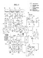
FIG. 5 is a schematic illustration of a renal failure blood treatment therapy system having a therapy fluid recirculation loop. -
FIG. 6 is a schematic illustration of one embodiment of a home use hemofiltration system of the present invention. -
FIG. 7 is a schematic view of another embodiment of a home use hemofiltration system of the present invention. -
FIG. 8 is a schematic view of one embodiment of a home use hemodiafiltration system of the present invention. -
FIGS. 9 to 11 show various embodiments of a home use blood treatment therapy that employs a regeneration unit that regenerates and reuses spent dialysis fluid and fluid ultrafiltered from the patient. -
FIGS. 12 and13 are alternative hemodialysis and hemofiltration systems using peristaltic pumps to pump the therapy fluid. -
FIG. 14 is an alternative hemodialysis system, wherein the flow of dialysate and blood are co-current. -
FIGS. 15 and16 are schematic views of one embodiment of a pneumatically controlled method and apparatus for controlling the volume of ultrafiltrate removed from the patient. -
FIGS. 17 to 22 are schematic flow diagrams of various embodiments for controlling the volume of ultrafiltrate removed from the patient via a single balance chamber. -
FIG. 23 is a schematic flow diagram illustrating various steps of one ultrafiltrate control method and apparatus employing a single balance tube. -
FIG. 24 is a schematic flow diagram illustrating one embodiment for controlling the volume of fluid exchanged with the patient and the volume of ultrafiltrate removed from the patient employing a single torturous path. -
FIGS. 25 and26 are schematic flow diagrams illustrating various features and advantages associated with an ultrafiltrate control method and apparatus that employs dual balance chambers. -
FIGS. 27A to 27D are schematic flow diagrams illustrating the valve operation and associated flow outcomes of another method and apparatus for controlling the volume of fluid exchanged with the patient and the volume of ultrafiltrate removed from the patient, which includes dual balance tubes. -
FIG. 28 illustrates one alternative valve arrangement for the balance tube volume control device of the present invention. -
FIG. 29 is a schematic flow diagram illustrating yet another embodiment for controlling the volume of ultrafiltrate removed from the patient, which includes dual torturous paths. -
FIGS. 30 and31 illustrate yet a further alternative embodiment for controlling the amount of fluid that has been exchanged with and the amount of ultrafiltrate removed from the patient, which includes a weight measurement system. -
FIG. 32 is an elevation view of one embodiment of an enhanced convection of hemodialysis filter of the present invention. -
FIG. 33 is a schematic view of one embodiment for the variable flow restriction located between the dual dialyzers of the present invention. -
FIG. 34 is a perspective view showing the cassette operably configured with flow actuation components of the dialysis systems of the present invention. -
FIG. 35 is a perspective view of one embodiment for operably coupling the solution bags to the renal failure therapy machine of the present invention. -
FIGS. 36 and37 are perspective views of embodiments for coupling the solution bags to the renal failure therapy machine, which also show one embodiment for enabling the machine to receive the cassette of the present invention. -
FIG. 38 is a perspective view of an alternative embodiment for pumping therapy fluid employing linear tubing pumps. -
FIG. 39 is a perspective view of one embodiment for operably coupling the solution bags to a system using linear tubing pumps. -
FIG. 40 is a schematic diagram showing one embodiment of a cassette of the present invention, which operates linear tubing pumps of the present invention. -
FIG. 41 is a schematic illustration of another embodiment of a cassette of the present invention, which operates with linear tubing pumps. -
FIGS. 42 and 43 are sectioned perspective views of different alternative implementations of one embodiment of a fluid heater of the present invention. -
FIG. 44 is a cutaway section view illustrating one embodiment for incorporating a balance chamber into a disposable cassette. -
FIG. 45 is a cutaway section view illustrating another embodiment for a home use balance chamber of the present invention. -
FIG. 45 is a perspective cutaway view of one embodiment of the balance tube of the present invention. -
FIG. 46 is a first embodiment of a control system for equalizing pressures on the fresh and spent sides of systems with a single balance tube. -
FIG. 47 is a second embodiment of a control system with pressure regulating valves for equalizing pressures on the fresh and spent sides of a system with a single balance tube. -
FIG. 48 is an embodiment of a control system for equalizing pressures on the fresh and spent sides of systems with two balance tubes. -
FIG. 49 is an embodiment of a control system with pressure regulating valves for equalizing pressures on the fresh and spent sides of a system with two balance tubes. -
FIGS. 50A-50C depict pressure regulating valves useful in embodiments of the present system. -
FIGS. 51 ,52A and 52B depict different embodiments of cassettes with balance tubes, the cassettes made from rigid plastic moldings or from flexible sheeting. -
FIGS. 53-54 depict additional embodiments of discrete balance tubes. -
FIGS. 55A-55B, 56A-56B depict additional embodiments of balance tubes and their component parts. -
FIG. 57 depicts a balance tube with stops at both ends. -
FIGS. 58A-58B depict additional embodiments of balance tubes with stops at both ends. -
FIGS. 59A-59B disclose embodiments with non-spherical separators. -
FIG. 60 depicts a balance tube embodiment made from a pre-formed medical balloon, with separate input/output ports for fresh and spent dialysate. -
FIGS. 61-63 depict balance tube embodiments with diaphragms as actuating elements. -
FIG. 64 depicts a balance tube with a positive displacement output. -
FIG. 65 depicts another embodiment of a balance tube with an internal reversing mechanism. -
FIG. 66 depicts a dialysis machine with pressure sensors for interfacing with a dialysis cassette. -
Fig. 67 depicts a dialysis machine with peristaltic pumps and with balance tubes on the cassette. - There are many embodiments of the present invention, of which only a few are described herein. The disclosure is intended to be descriptive but not limiting.
- One embodiment is a dialysis cassette for a renal therapy machine. The cassette includes a housing configured and arranged to be placed in the machine, a flexible membrane attached to the housing, the membrane and housing cooperating with the machine to perform a valving function controlling flow of a renal failure therapy fluid, two pumping chambers within the housing for pumping the renal failure therapy fluid, at least one balancing system and at least four valves operably connected to the at least one balancing system, the balancing system operably connected to the pumping chambers, the at least one balancing system configured to equalize the flow of the renal failure therapy fluid to and from a dialyzer or a patient, and at least one pressure sensor for sensing a pressure of the renal failure therapy fluid and conveying a signal representative of the pressure to a controller of the machine, wherein the controller and the signal are configured to control the valves for flow of renal failure therapy fluid to and from the at least one balancing system so that a pressure of the fresh renal failure therapy fluid to the at least one balancing system is equal to a pressure of spent renal failure therapy fluid to the at least one balancing system.
- Another embodiment is a dialysis cassette for a renal therapy machine. The cassette includes a housing for the cassette configured and arranged to be placed in the machine, a flexible membrane attached to the housing, the membrane and housing cooperating with a controller of the machine to operate valves controlling flow of a renal failure therapy fluid, two pumping chambers within the housing for pumping the renal failure therapy fluid, at least one balancing system operably connected to the pumping chambers, and at least four valves operably connected to the at least one balance tube, wherein the at least one balancing system is configured to equalize the flow of the renal failure therapy fluid to and from a dialyzer or a patient, and optionally, a temperature sensor for sensing a temperature of the renal failure therapy fluid within the at least one balance tube, a separator in the at least one balancing system, the separator configured to move freely within the balancing system, wherein the controller is configured to control the valves for flow of renal failure therapy fluid to and from the at least one balancing system so that a pressure of the fresh renal failure therapy fluid to the at least one balancing system is equal to a pressure of spent renal failure therapy fluid to the at least one balancing system.
- Another embodiment is a method of equalizing fluid flow in a dialysis cassette for a renal therapy machine. The method includes steps of providing a renal failure therapy machine with a controller and a dialysis cassette therefor, the cassette and the controller configured for equalizing flow of fresh and spent dialysis fluid, sequentially pumping the fresh and spent dialysis fluid into at least one balancing system of the cassette, optionally, selecting an operating pressure for the at least one balancing system, and controlling a flow of the fresh and spent dialysis fluid into the at least one balancing system so that a pressure of the fresh dialysis fluid in the at least one balancing system when the at least one balancing system is filled with fresh dialysis fluid equals a pressure of the spent dialysis fluid in the at least one balancing system when the at least one balancing system is filled with spent dialysis fluid, and if an operating pressure has been selected, wherein the pressures in the at least one balancing system equal the operating pressure.
- Another embodiment is a method of equalizing fluid flow in a dialysis cassette for a renal therapy machine. The method includes providing a renal failure therapy machine with a controller and a dialysis cassette therefor, the cassette and the controller configured for equalizing flows of fresh and spent dialysis fluid, sequentially pumping the fresh and spent dialysis fluid into at least one balancing system of the cassette, the at least one balancing system operably connected to at least four valves for inflow and outflow of dialysis fluid, sensing a pressure of the fresh dialysis fluid and the spent dialysis fluid in the at least one balancing system, and controlling a flow of the fresh and spent dialysis fluid into the at least one balancing system so that a pressure of the fresh dialysis fluid in the at least one balancing system when the at least one balancing system is filled with fresh dialysis fluid equals a pressure of the spent dialysis fluid in the at least one balancing system when the at least one balancing system is filled with spent dialysis fluid.
- Air bubble detectors, heating elements, pressure sensors, temperature sensors, etc. are also integrated into the cassette for both the dialysate management and extracorporeal blood sides as necessary to allow for a safe treatment for the patient and reliable operation of the system.
- Recently published studies show that ultrapure dialysate produces better outcomes when compared to standard dialysate. The prepackaged, sterilized dialysate used in one embodiment of the present invention may produce outcomes that are as good as, if not better than, ultrapure dialysate. It should be appreciated however that the present invention is not limited to the use of prepackaged dialysate bags, but instead, may use dialysate prepared on-line or at home. The advantage of the online system to the patient is to eliminate the solution bags and the space they consume. The dialysate, whether supplied from a sterilized bag or made online, may also be recirculated in one or more loops using one or more charcoal or sorbent cartridge.
- One preferred at home generation system is described herein. That system uses a reservoir, such as a five liter bag of sterile dialysate installed in a rigid container. A shunt is placed across the dialyzers at start-up for rinsing and priming. During treatment, a sorbent cartridge that operates using an urea exchange or a binding urea is placed in the post dialyzer or ultrafilter ("UF") loop. The sorbents may remove other substances, such as β2 microglobulin or phosphate, etc. A series of infusion pumps simultaneously pull dialysate from the sterile bag, through a heater, through an ultrafilter and through the shunt to the sorbent cartridge. If necessary, an infusate such as a gamma sterilized infusate that includes calcium, magnesium, and potassium is added to the dialysate reservoir.
- After the solution is heated and ready for treatment, the blood treatment machine prompts the user to install the cassette. The blood circuit can be primed with a saline bag hooked via the arterial bloodline or by backfiltering dialysate through the blood treatment venous filter. Air bubble detectors, heating elements, pressure sensors, temperature sensors, etc., are integrated into the cassette for both the dialysate and extracorporeal blood circuits as necessary to enable a safe treatment for the patient and a system that operates reliably.
- The patient is then hooked to the arterial and venous needles and the treatment begins. For short therapies, the dialysate flow can be relatively high, for example, three hundred ml/min for three hours or one hundred ml/min for up to eight hours. The dialysate/UF flow control pumps control the flow to and from the dialyzers. By increasing the frequency of the pumps that pull the effluent dialysate from the arterial dialyzer, the fluid accumulated in the patient in the interdialytic period is removed. Portions of the dialysate/UF flow control pumps are integrated into the cassette along with a portion of the blood pump in one embodiment or are alternately provided separate from the cassette and integrated into the machine.
- Due to the impracticality of hanging and storing bags, solution-bag based systems are limited to a total practical amount of dialysate per treatment. The sorbent-based fluid regeneration system enables a therapy that uses more dialysate and thereby provides enhanced waste clearance. Providing an increased amount of dialysate beneficially enhances the clearance of waste products from the renal patient. For example, the sorbent cartridge could be used for a four hour treatment at two hundred to two hundred fifty ml/min dialysate flow or about fifty liters of dialysate over the entire treatment, which would provide an increased volume of dialysate and better waste clearance over other hemofiltration systems. The sorbent system is also applicable to the hemofiltration systems described herein, making even predilution HF possible. For hemofiltration, an additional reusable ultrafilter is provided to maintain redundancy of bacteria and endotoxin removal.
- The sorbent-based regeneration system is particularly suited for home use because it eliminates the need to store numerous solution bags, eases therapy setup and does not require a connection to the patient's water tap. Also, the patient does not have to connect a tubing set. The patient instead places the cassette into the machine, adds an initial five liter bag of sterile dialysate to the reservoir and starts the automated priming sequence. When the priming is complete, the patient connects himself/herself to the blood circuit and starts the dialysis therapy.
- The portable device, the use of prepackaged solutions or an on-line fluid generation system and the use of a disposable set each provide dialysis patients with the flexibility and freedom that previously has only been available to peritoneal dialysis patients. Because there is no dedicated water hookup and the present machines are small, it is possible for a patient using the present systems to travel and perform blood therapy dialysis sessions on the road. Many of the systems and methods described herein can be adapted to work with in-center solutions, and many of the aspects of the present invention are not limited to home use.
- High convection hemodialysis is believed to be more effective than conventional hemofiltration because it has convective clearance in addition to the diffusive transport of toxins. The therapy is expected to provide good waste clearance of small, middle and large molecules from even end-stage renal patients.
- The device is well-suited for use in hospitals for acute patients for situations in which a required water supply and dialysis proportioning system are unavailable. The present device is easier to set up and use in an intermittent acute setting.
- The present invention provides multiple methods and apparatuses for not only controlling the amount of dialysate or substitution fluid that is delivered to the extracorporeal circuit or dialyzer but also for accurately controlling the amount of ultrafiltrate removed from the patient. The various alternatives can be divided into three main types. One type of control used is a pneumatic control based on Boyle's Law. Here, the fluid pumps are placed in fluid communication with a known volume of air. The system uses Boyle's Law to place into an equation a series of known or measured values to calculate accurately the amount of fluid (e.g., versus air) from a pump chamber pumped to the patient. The method and apparatus use fluid and air pressure signals generated and converted to numbers that are placed into an equation.
- The equation yields the fluid volume pumped per cycle or stroke of the pump. The Boyle's law system in one embodiment provides accurate information on an end stroke or pump cycle basis but not necessarily on a real time basis. The present invention also includes a system and method based on Boyle's Law that generates flow rate data on a real time basis.
- A second large category of volumetric control includes the use of a balancing device. Many embodiments for employing such balancing device are discussed below.
- The balancing device embodiments may be parsed into two main subgroups. One sub-group uses a single balancing device. Another sub-group includes dual balancing devices.
- The present invention also teaches and discloses a plurality of different types of balancing devices. In one embodiment, the system employs one or two balancing chambers. In another embodiment, the system employs one or two balancing tubes. The balancing tubes include a tubular housing with a piston or ball like separator within the housing. The separator acts similarly to the membrane or diaphragm of the balance chamber.
- A third type balancing device is one or more torturous paths. The torturous path is defined in one embodiment by a disposable cassette as an elongated channel. The diameter or cross-sectional area of the channel is configured so that bulk movement of fresh or effluent dialysate can efficiently move an existing bulk of fluid within the torturous path. That is, fresh dialysate in bulk moves a bulk of spent or effluent dialysate currently residing in the path to drain. In the next cycle, spent or effluent dialysate in bulk pushes the bulk of fresh fluid just introduced into the torturous path to the patient or dialyzer. The cross-section and the length of the path are configured to minimize an amount of mixing of the fresh and spent fluids at the ends of the bulks of fluid.
- The various volumetric balancing devices can be used with many different types of pumps, such as a peristaltic pumps, membrane pumps, gear pumps or a combination thereof. A single pump may be used with the balancing devices. Separate fresh and spent dialysate pumps may be used alternatively. Further, a separate ultrafiltrate pump is also contemplated and discussed, which enables the main pump(s) to be dedicated to pumping an equal volume of fluid to and from the patient.
- The third major type of fluid management uses a weight or scale to measure the amount of fluid delivered to the patient and the amount of fluid removed from the patient. In an embodiment illustrated below, fluid bags are placed on a stand, which is coupled to a shaft. At one end, the shaft couples to a rolling diaphragm. The rolling diaphragm, in combination with other apparatus, defines a closed but variable volume. As the weight in the fluid bags fluctuates, a pressure within the volume also fluctuates. A pressure sensor senses the pressure and the controller or processor of the machine processes the signal from the pressure sensor to develop a corresponding weight signal. The weight signal is then used to determine how much fluid has been delivered and or removed from the patient. In one embodiment, fresh and spent fluid bags are measured by the same weight sensing device, so that the system expects to see a net overall weight gain over time due to the ultrafiltrate removed from the patient. A load cell could also be used for this application.
- As illustrated in detail below, the present invention provides multiple embodiments for other components of the systems and methods of the present invention, such as the fluid heater, the balancing devices, the disposable cassette, bag positioning and other important features of the present invention. For example, the present invention includes an access disconnection sensor ("ADS"), which can detect when either the arterial or venous needle has been removed inadvertently from the patient during treatment. Further, various pressure relief schemes, integrity tests, etc., are discussed herein, which are important especially for a home-use machine, which the patient may be use while sleeping.
- Additional features and advantages of the present invention are described in, and will be apparent from, the following Detailed Description of the Invention and the figures. The present invention provides various apparatuses and methods for a home hemodialysis ("HHD") treatment that increases and enhances the amount of backfiltration during treatment. It is important to note that even though this system is designed for the home, it is also suitable for use in a clinic, acute renal treatment center or self care center. The system uses a disposable fluid management system, which may include a disposable set having a disposable cassette or tubing organizer (referred to herein collectively as cassette). The cassette houses at least a portion of at least one of the dialysate and extracorporeal flow paths. In one embodiment, two small high flux dialyzers are connected fluidly and in series to the cassette. In one embodiment, dialysate and blood flow in a countercurrent manner through the dialyzers with respect to each other. A restriction is placed between the two dialyzers in the dialysate flow path. The restriction is variable and adjustable in one embodiment to account for different treatment conditions or to be adjusted during a single treatment. The restriction is alternatively fixed, such as an orifice plate with a restricting orifice.
- Due to the restriction between the filters, a positive pressure is built in the venous dialyzer (first dialyzer to receive dialysate but second dialyzer to receive blood in countercurrent arrangement), intentionally causing a relatively high degree of backfiltration. Depending on the size of the restriction between the dialyzers, that backfiltration causes a significant flow (e.g., 10 to 70 percent of total dialysate flow) of dialysate through the high flux venous membranes and into the blood circuit. The backfiltered solution provides convective clearance. In one embodiment, ultrafiltrate is removed from the patient via the arterial dialyzer (first dialyzer to receive blood but second dialyzer to receive dialysate in countercurrent arrangement).
- The diffusion of dialysate into the venous dialyzer and removal of dialysate from the arterial dialyzer causes a convective transport of toxins from the patient. Additionally, the dialysate that does not move directly into the extracorporeal circuit (e.g., the other percentage of the dialysate) but instead flows across the membranes of both dialyzers, providing a diffusive clearance of waste products. This system, referred to herein as an enhanced convection hemodialysis ("ECHD") system. Similar to a hemodiafiltration system, which provides both convective and diffusive clearances. The system in one embodiment is configured for home use, wherein at least a portion of the dialysate and extracorporeal flow paths are sterilized and provided in a disposable set, which is loaded into a machine having multiple pumps, a heater, valve actuators and the like.
- Referring now to the drawings and in particular to
FIG. 1 , one embodiment of the renalfailure therapy system 10 of the present invention is illustrated.System 10 employs two or more high flux hemodialyzers, such as avenous dialyzer 20 and anarterial dialyzer 30. In one embodiment, hemodialyzers 20 and 30 are relatively small, e.g., on the order of one quarter to three square meters of membrane surface area. Dialyzers or hemodialyzers 20 and 30 are relatively high flux dialyzers, e.g., having a UF coefficient of eight milliliters of water diffused per hour per millimeters Hg pressure or greater (as used herein, the term "flux" refers to the above UF coefficient, which measures the ease of water transport through the membrane, expressed in milliliters/hour/millimeter Hg. - As discussed above, hemodialyzers 20 and 30 cause backfiltration in the
venous dialyzer 20 of a relatively large portion of the fresh dialysate. The backfiltered dialysate and the fluid accumulated during the interdialytic period is ultrafiltered or removed from thepatient 42 via thearterial dialyzer 30. The fluid not backfiltered flows across the semi-permeable membrane in the arterial 30 and venous 20 dialyzers, enablingsystem 10 to provide both diffusive and convective removal of waste from the patient's blood. - In one home use and in-center embodiment shown in
FIG. 1 , sterile dialysate is stored in bags orcontainers System 10 in the illustrated embodiment employspumps volume measuring device pumps 22 to 28. That measurement in one embodiment informs a controller or microprocessor how much fluid (or air) has been pumped. The controller or microprocessor compares the actual amount of fluid pumped to an expected amount of fluid pumped and adjusts the pumping rates accordingly to make-up or back-off the delivery of new fluid todialyzers capacitive measuring devices 32 to 38 can sense when a larger volumetric error in the system occurs and trigger, for example, an error message (e.g., when air becomes trapped in the system or a majority of a stroke length is missed). - It should be appreciated that the present invention is not limited to capacitive fluid volume measuring but can use instead other suitable types of volume measuring. Moreover, the present invention is not limited to volume measuring but instead can employ balancing devices that ensure a set amount of dialysate is pumped to the dialyzers, from the dialyzers and from the
patient 42. Further alternatively, fluid pump management can be accomplished on a mass basis, via one or more scales. Still further, flowrate and volume pumped can be calculated based on a number of pump strokes, such as a number of peristaltic pump revolutions based on a number of steps of a stepper motor, based on a sensed amount of movement of a linear of rotating pump actuator or via a device that operates according to Boyle's Law. All of those measuring alternatives are included in the term "volume measuring device." Control using the volume measuring device can be closed loop, where the actual amount of fluid delivered is monitored, or open loop, where the scheme relies on the inherent accuracy of the pump and perhaps motion control feedback, such as a monitoring of number of step pulses sent to drive the motor, linear encoder feedback or rotary encoder feedback, etc. -
FIG. 1 illustrates twopumps Pump Set 1 and twopumps Pump Set 2. It is important to note that a single pump may alternatively be used in place of each set of pumps, e.g., one to input dialysate to the dialyzers and one to remove dialysate from the dialyzers and UF from the patient, however, that configuration would create pulsatile or uneven flow, which is less desirable. In the illustrated configuration, a first pump of each set is pulling fluid from the pump set's source, while a second pump of each set is pushing fluid towards the pump set's destination. After that set of pump strokes, the roles of the pumps in the respective sets alternate, so that the first pump (now full of fluid) pushes fluid towards the pumps set's destination, while the second pump (now empty) pulls fluid from the pump set's source. The above cycle is repeated multiple times. -
Pump Set 1 inputs fresh dialysate frombags 14 to 18 to thesystem 10 andPump Set 2 removes a volumetric equivalent of the fluid pumped byPump Set 1 and any fluid removed frompatient 42 during the course of the treatment. As illustrated, fresh dialysate is pumped viapumps sources venous dialyzer 20. Arestriction 40 is located betweenvenous dialyzer 20 andarterial dialyzer 30.Restriction 40 builds pressurevenous dialyzer 20, so that a relatively large amount of fresh dialysate enteringvenous dialyzer 20 is forced through the walls of the membranes insidevenous dialyzer 20 and into the extracorporeal orblood circuit 50. The other portion of the fresh dialysate enteringvenous dialyzer 20 flows across the membranes insidevenous dialyzer 20, throughrestriction 40 and intoarterial dialyzer 30. - Convective clearance occurs when a volumetric equivalent of the fluid backfiltered through
venous dialyzer 20 is removed from thearterial dialyzer 30. Also, a diffusive transport of toxins occurs across bothdialyzers blood circuit 50 and the flow of dialysate. Over the total therapy, the total amount of fluid removed from thearterial dialyzer 30 is greater than the total amount of dialysate supplied to thevenous dialyzer 20, accounting for an amount of UF removal prescribed for the therapy. - The following example further illustrates one preferred therapy for the present invention. In the example, pumps 22 and 24 of
Pump Set 1 infuse eighteen liters of dialysate fromsources blood circuit 50 through the membrane walls ofvenous dialyzer 20. Fifty ml/min of dialysate passes through thevenous dialyzer 20,restriction 40 and intovenous dialyzer 30.Pumps Pump Set 2 remove the total of eighteen liters of dialysate frombags venous dialyzer 20.Pumps Pump Set 2 remove that twelve liters, the six liters of dialysate that is not backfiltered intoblood circuit 50 plus any fluid ultrafiltered from the patient. - The addition and removal of the twelve liters of dialysate from
blood circuit 50 over the two hour therapy yields an overall convective removal according to the equation HF stdKt/V of - 2, which has been reported to be a suitable daily amount (see Jaber B T, Zimmerman D L, and Leypoldt J K., Adequacy of Daily Hemofiltration: Clinical Evaluation of Standard KtlV (stdKt/V), Abstract . Additionally, over the course of two hours, six liters of dialysate was used for diffusive clearance via the dialysate gradient across the membranes ofdialyzers - Referring additionally to
FIGS. 2 and 3 , dialyzers 20 and 30 as well as many other flow components described herein are provided in one preferred embodiment attached to a disposable cassette.Disposable cassette 100a can otherwise be referred to as an organizer, disposable, disposable set, etc.Disposable cassette 100a includes at least a portion of theextracorporeal circuit 50 and dialysate flow path 60 (seeFIG. 1 ) for the renal failure therapy treatment (e.g., all ofextracorporeal circuit 50 is integrated intocassette 100a with the exception of the tubing going to and from the patient as illustrated inFIGS. 2 and 3 ).Disposable cassette 100a provides a space efficient apparatus for handling the dialysate or therapy fluid flow portions of the many pumps and valves described herein, which are actuated pneumatically or mechanically as described below.Cassette 100a is therefore well suited for home use, where space, capability and resources are limited. - In one preferred embodiment,
disposable cassette 100a and associated attached tubing are gamma sterilized and sealed prior to use. Alternatively, sterilization via ethylene oxide or electron beam is employed. The patient or operator opens the seal just prior to use, insertscassette 100a into the therapy machine for a single use and then discards thecassette 100a and associated tubing. Whilecassette 100a and flowpaths cassette 100a and flowpaths - Incorporation of Cassette and ECHD System
- Referring to
FIGS. 1 to 3 , beginning from thearterial access 44a of thepatient 42, the extracorporeal orblood circuit 50 includes apressure sensor 46, labeled PT1. PT1 is alternatively a pressure switch with the ability to stop blood flow prior to reachingblood pump 48. As a safety measure,system 10 in one embodiment includes a multitude of electrodes (not shown), such as two to four electrodes, which provide an access disconnection sensor, which is integrated half in thearterial line 44a and half in thevenous line 44b to detect access disconnection ofpatient 42 from thesystem 10. An alternative mechanism for detection of accidental needle disconnections is the use of a conductive blanket underneath the patient's access. The presence of blood changes the conductivity of the blanket and sets off an alarm and stop the pumps. -
Blood pump 48 isperistaltic pump 48 in one embodiment and is located between pressure sensor PT1 and adrip chamber 52a withintegral pressure transducer 46, labeled PT2. Thedrip chambers 52a to 52c remove air from the fluids passing through the drip chambers. One, a multiple of or all thedrip chambers 52a to 52c in an alternative embodiment includes an associatedlevel sensor 68a to 68c. Those sensors are connected to or integrated into the associated drip chambers.Level sensors 68a to 68c sense and indicate the level or height of dialysate or therapy fluid in the dialyzer.Blood pump 48 is alternatively a volumetric pumping device other then a peristaltic pump, such as a diaphragm pump or centrifugal pump.Blood pump 48 can also be bidirectional for system priming as discussed below.Pressure sensor PT2 46 is alternatively not associated with a drip chamber, where for example pressure transducers are used instead. Pressure sensors PT1 and PT2,drip chamber 52a as well as thetubing 102 forperistaltic pump 48 are all connected tocassette 100a. - After
drip chamber 52a, blood flows out of thehousing 104 ofcassette 100a into a the relatively small, high flux dialyzerarterial dialyzer 30. As seen inFIG. 2 ,arterial dialyzer 30 andvenous dialyzer 20 are attached to an end ofhousing 104 ofcassette 100a. Blood then flows from thearterial dialyzer 30 to thevenous dialyzer 20, back intohousing 104 ofcassette 100a and through asecond drip chamber 52b.Drip chamber 52b also has anintegral pressure sensor 46, labeled PT3. PT3 is alternatively provided without a drip chamber when, for example, pressure transducers that coupled directly to the line are used instead. - An
air bubble detector 54 labeled ABD is located downstream fromdrip chamber 52b inblood line 50. A venous line clamp orvalve 56, labeled V1, which may be cassette-based or provided external tocassette 100a, and which shuts down blood flow if air is detected inline 50 bydetector 54, is located between theair detector 54 andarterial access 44b, which returns blood topatient 42. An air level sensor (not illustrated) ondrip chamber 52b is used alternatively or in addition toABD 54. To detect air in the blood, a level detect scheme is alternatively or additionally provided withdrip chamber 52b orpressure transmitter 46, labeled PT3. For example, an ultrasonic sensor can be placed on opposite sides of the drip chamber. The sensor generates a signal that depends upon the percentage of air in the blood that passes between a transmitting and receiving positions of the sensor. Under normal operation, when no air is present, the blood withindrip chamber 52b resides at a relatively steady level, although level fluctuations do occur due to changes in pressure, amount of blood pumped, etc. A threshold level of blood inchamber 52b does exist below which the blood should not drop. When air in the blood lines is present, the blood level in thechamber 52b is lower than threshold level, triggering an alarm from the alternative air/blood detector. It is important to note that an air detector and line clamp may be used online 44a, if required by rinse, prime or blood rinseback. -
Dialysate flow path 60 is also located primarily in the housing of organizer orcassette 100a. The dialysate is supplied initially in dialysate or therapyfluid supply bags FIGS. 4 and9 to 11 , the source is an on-line source or other type of non-prepackaged source. In the embodiment illustrated inFIG. 1 , a minimum of one infusion bag is provided and in one preferred embodiment multiple bags, such as threesources 14 to 18 are provided.FIG. 1 also illustrates that the system is provided initially with anempty drain bag 12, which is filled with spent solution from thesupply bag supply bags supply bags 14 to 18 is used to receive spend fluid and UF. The bag sequencing is controlled as illustrated byvalves 56, labeled V8 to V14. - Dialysate or therapy solution flows from one of
sources 14 to 18 to the volumetric diaphragm pumps 22 and 24 ofset 1. The volumetric accuracy of pumps is confirmed by monitoring. As discussed above, it is desirable to use two alternating solution delivery pumps 22 and 24 to limit the amount of pulsatile flow. As a safety measure, the diaphragms of each of thepumps 22 to 28 are configured so that if they leak, the can only leak externally. Any leaks collected externally frompumps 22 to 28 are then diverted towards a moisture sensor built into thecassette 100a, machine and/or cassette/machine interface, which senses such leak and signals: (i) an alarm; (ii) to shut down pumps 22 to 28 and 48; and (iii) to take any other appropriate action. - Suitable pneumatically and mechanically driven medical fluid pumps and diaphragms therefore are described in commonly owned
U.S. Pat. No. 7,238,164 , entitled Systems, Methods And Apparatuses For Pumping Cassette-Based Therapies, the teachings of which are incorporated herein by reference. The pumps and pumping technology currently used in the HomeChoice® series of APD devices, as embodied inU.S. Pat. No. 5,431,626 and its associated family of patents, the teachings of each of which are incorporated herein by reference, are also suitable, as are various pumping technologies described in commonly ownedU.S. Pat. No. 6,814,547 , entitled "Medical Fluid Pump," and commonly-ownedU.S. Pat. Appl. Publ. 2005/0131332, filed November 4, 2004 , entitled "High Convection Home Hemodialysis/Hemofiltration and Sorbent System," the teachings of each of which are incorporated herein by reference. - As discussed above, each of the
pumps 22 to 28 operates individually with avolume measuring device 32 to 38. In one preferred embodiment,volume measuring devices 32 to 38 are capacitance fluid volume sensors, indicated inFIG. 1 by dashed lines representing the associated capacitor plates. One embodiment of a capacitance sensor is disclosed in greater detail in the commonly owned patent application entitled, "Capacitance Fluid Volume Measurement,"U.S. Pat. No. 7,107,837 , incorporated herein by reference. That capacitance sensor uses capacitance measurement techniques to determine the volume of a fluid inside of a chamber. As the volume of the fluid changes, a sensed voltage that is proportional to the change in capacitance changes. Therefore, the sensor can determine whether the chamber is, for example, empty, an eighth full, quarter full, half full, full, or any other percent full. Each of these measurements can be made accurately, for example, at least on the order of the accuracy achieved by known gravimetric scales or pressure/volume measurements. Capacitance sensing, however, is simpler, non-invasive, inexpensive and is operable with continuous, non-batch, type pumping operations. - Generally, the capacitance C between two capacitor plates changes according to the function C=k x (S/d), wherein k is the dielectric constant, S is the surface area of the individual plates and d is the distance between the plates. The capacitance between the plates changes proportionally according to the
function 1/(R x V), wherein R is a known resistance and V is the voltage measured across the capacitor plates. - The dielectric constant k of medical fluid or dialysate is much higher than that of air, which typically fills a pump chamber (such as
pump chambers FIG. 2 , which are part ofpumps 22 to 28 inFIG. 1 ) that is empty or at the end of a pump out stroke. In one embodiment, one of the capacitance plates is moveable with the volume of fluid entering or exiting thechambers 122, yielding the changing distance, Δ d, between the plates a factor in determining capacitance. Likewise the surface area, S, of the capacitance plates could be varied. In one preferred embodiment shown figuratively inFIG. 1 , thecapacitance plates housing 104 ofcassette 100a. In that instance, the surface area S is also fixed, leaving the change in the dielectric constant k to account for the change in capacitance as thepump chambers 122 to 128 are filled or emptied of dialysate. - As at least one flexible membrane positioned within
chambers 122 to 128 expands and fills with medical fluid, the overall capacitance changes, i.e., increases, creating a high impedance potential across the capacitor plates, one of which is grounded, the other of which is active. That high impedance potential is indicative of an amount of fluid in thechambers 122 to 128. If the sensed potential does not change, or does not change enough when it is expected to change, the system controller recognizes such lack of change as air that has been trapped in the dialysis fluid and requires appropriate action. - A capacitance sensing circuit is provided, which amplifies the high impedance signal to produce a low impedance potential. The low impedance is fed back to the,
capacitance plates 32 to 38 and is used to protect the sensitive generated capacitance signal from being effected by outside electrical influences. The amplified potential is also converted to a digital signal and fed to a the system controller, where it is filtered and or summed. A video monitor having a graphical user interface can then be used to visually provide a volume and/or a flowrate indication to a patient or operator based on the digital signal. Additionally, the controller uses the flowrate and volume information to ensure that Pump Set 2 (pumps 26 and 28) withdraws the appropriate amount of fluid fromarterial dialyzer 30, namely, the amount of dialysate pumped from Pump Set 1 (pumps 22 and 24) plus the prescribed amount of UF removed from the patient. - An additional use for capacitance plates or
volume measuring devices 32 to 38 is to detect a leak across pump valves V3 and V5, V2 and V4, V15 and V16 and/or V17 and V18. Those valves cycle and alternate during the pump-in and pump-out strokes ofpumps system 10, such as fluid container valves V8 to V14. The pump valves are therefore more susceptible to leakage than are other valves and are relatively critical to the operation ofsystem 10. - The pump valves operate in alternating pairs. For instance, to deliver fluid into
pump 22, valve V3 is opened while valve V5 is closed. Conversely, to push fluid frompump 22, valve V3 is closed while valve V5 is opened. If both valves are either opened or closed while a pump stroke takes place, volumetric error occurs. The present invention contemplates a method and apparatus for testing valves V3 and V5, usingvolume measuring devices 32 to 38. - The valve test in one embodiment utilizes the fact that the pump has flexible fluid membranes that are crimped between a fixed volume pump chamber. When a pump-in stroke takes place, the membranes fill with fluid expanding the membrane. The corresponding pump inlet valve (e.g., valve V3) is then closed, trapping fluid within the flexible pump chamber membranes. A partial pump-out stroke is attempted either via a mechanical piston or positive/negative pneumatic pressure. The pressure exerted is not enough to damage the pump components but is enough so that if either inlet or outlet valves (e.g., V3 and V5) is faulty or leaking, fluid would flow, creating a volume change that would be sensed by
volume measuring devices 32 to 36. - If the valves close properly, and assuming dialysate to be incompressible, the small pressure exerted should move no fluid and produce no detectable volume change. If a leak is present, a volume change occurs and is detected, causing the controller to issue an alarm condition or take other appropriate action. The above-described test can be performed at the start of therapy and/or intermittently and periodically throughout therapy, e.g., every five minutes or every one thousand strokes. The test, it should be appreciated, can at least detect which set of pump valves V3 and V5, V2 and V4, V15 and V16 or V17 and V18 is leaking. The test is applicable to all types of medical fluid systems, including blood therapy systems, congestive heart failure systems and peritoneal dialyzer systems.
- The
chambers 122 to 128 andhousing 104 ofcassette 100a form a first portion of a clamshell, the second portion being formed by the renal therapy machine. The first and second portions house at least one flexible membrane and the dialysate when dialysate is present. The portions are rigid and form a fixed volume in one preferred embodiment. The portions form the shape of and also house thecapacitor plates 32 to 38. That is, one of the capacitor plates is housed incassette 100a, while the other is housed inside the therapy machine. Alternatively, both plates are housed in the therapy machine, one on either side of the cassette. As stated above, either the cassette or machine (whichever houses the active rather than the ground capacitor plate) houses an additional guard or shield plate that provides noise protection for the high impedance signal transmitted from the active capacitor plate. - As an alternative to the capacitance volume sensor described above, the volume or mass of dialysate fluid flowing through the
pumps 22 to 28 can be determined using other methods, such as through an electronic scale or balance. In other alternative embodiments, the mass or volume of dialysate flowed in any of the systems described herein can be sensed using various types of medical grade flowmeters, orifice plates, mass flow meters or other devices employing Boyle's Law. Further, the Fluid Management System ("FMS") technology used in HomeChoice®, as embodied inU.S. Pat. No. 5,431,626 and its associated family of patents, the teachings of each of which are incorporated herein by reference, is also suitable for use in the present invention. A pneumatically controlled system employing this technology is discussed in more detail below. Conductivity sensors may also check for conductive and nonconductive states across the valves, detection of valve leaks is easy with this method. - Still further alternatively, fluid balancing chambers or match flow equalizers may be used, such as those described in
U.S. Pat. No. 5,486,286 , assigned to the assignee of the present invention, incorporated herein by reference, which are also employed in the System 1000™ produced by the assignee of the present invention. The balancing chambers or flow equalizers are integrated in the cassette in one embodiment and require a separate pump or pressurization source. The chambers or equalizers would manage fresh dialysate on one side of a diaphragm and the spent dialysate on the other side of the diaphragm, matching the volume flow of fresh and spent dialysate. A separate pump is then used to ultrafiltrate fluid frompatient 42 accumulated between patient sessions. Peristaltic pumps may also be used to pump dialysate todialyzers FIG. 12 . Systems employing balancing chambers and other volumetric control devices are discussed in more detail below. - Referring still to
FIGS. 1 to 3 ,valves 56 labeled V2, V3, V4 and V5 control which pump is filling and which pump is exhausting dialysate at any given time. Those valves, as well as most if not all the valves of the systems described herein have an electromechanical portion housed inside the blood treatment machine and afluid flow portion 156, shown inFIG. 2 . Dialysate or renal therapyfluid exiting pumps heater 58.Heater 58 is located alternatively prior to volumetric diaphragm pumps 22 and 24.Heater 58 may be any suitable type of electrical medical fluid heater, such as a plate (electrical resistance) heater, infrared or other radiant heater, convective heater, and any combination thereof.Heater 58 is illustrated as an in-line heater. As seen inFIG. 2 , dialysate flows through a flexiblemembrane heating portion 158 ofcassette 100a. The electronics and other hardware associated withheater 58 are located inside the renal failure therapy machine.Heater 58 is located alternatively to batchheat solution bags -
Valve 56 labeled V6 provides a bypass that enables solution at too high or too low a temperature to be diverted to a point upstream ofpumps dialyzers blood circuit 50. To that end,temperature sensor 62 labeled T2 senses and provides feedback to the controller ofsystem 10 indicating the temperature ofdialysate leaving heater 58. Thetemperature sensor 62 could be a thermocouple or IR sensor or thermistor, which is housed inside, integral with or directly adjacent to a conductivity sensor probe 63. Conductivity sensing is temperature dependent, so it is logical to locate the twosensors 62 and 63 together or directly adjacent to each other. - A suitable location for the temperature sensor/conducting sensor is, for example, at sensor location T2, T3 which senses the conductivity of the fluid prior to the
fluid reaching dialyzers containers - A
pressure sensor 46 labeled PT4 measures the pressure of the fluid flowing tovenous dialyzer 20 and in one embodiment is provided in association with anadditional drip chamber 52c that purges air throughvent 64c and ventvalve 56 labeled V19. Sensor PT4 andchamber 52c are located alternatively prior to volumetric diaphragm pumps 22 and 24. - The dialysate next flows into
venous dialyzer 20. The membranes housed inside venous dialyzer are high flux membranes as discussed above. The dialysate flow path connects to the venous 20 and arterial 30 dialyzers via therestriction 40.Restriction 40 provides backpressure that drives a significant amount of the dialysate through the high flux membranes of thevenous dialyzer 20 and directly into the blood flowing through the membranes insidevenous dialyzer 20. Restriction can be set to backpressure ten to ninety percent of the dialysate enteringvenous dialyzer 20 into the bloodline. As discussed above,restriction 40 can be set or variable. If a fixed restriction is desired, it is possible to use a single dialyzer rather using the twodialyzers FIG. 1 . A dialyzer having an internal flow restriction suitable for use in place ofitems FIG. 1 is described in commonly ownedU.S. Pat. No. 5,730,712 , entitled "Extracorporeal Blood Treatment Apparatus and Method", incorporated herein by reference. That dialyzer as indicated is limited to having a fixed orifice. - As alluded to above, it is desirable for a number of reasons that
restriction 40 be a variable restriction. For one reason, different patients may respond to a therapy that is more convective or more diffusive. From a cost and manufacturing standpoint, it is desirable to have a unit that can be adjusted for any patient rather than "custom" units fitted with the necessary flow restriction. Second, it is very possible that the patient and doctor will not know initially what the optimal percentage convective clearance versus diffusive clearance breakdown is, requiring some period of experimentation and optimization. Moreover, it may be desirable for a patient to perform a first treatment using a first percentage convective clearance versus diffusive clearance and later in the week, the next day or later in the same day perform a second treatment using a different percentage convective clearance versus diffusive clearance. - Still further,
system 10 has the capability of varying the percentage convective clearance versus diffusive clearance over a single therapy session or treatment, for example in step increments or continuously. Such changes can be made as gradually or quickly as desired and span as great a range as desired, e.g., starting with 90 percent convective and ending with 90 percent diffusive. It may be determined that it is desirable to clear molecules of a particular size or range of sizes or molecules of a particular type during a certain point in the therapy, e.g., at the beginning or end.Variable restriction 40 also makes it possible to repeat certain settings or patterns of settings during a single treatment. - The present invention contemplates at least three levels of variability for
restriction 40. The first level can be referred to as "semi-fixed". Here, the restriction could use a fixed orifice restriction plate, but whereinrestriction 40 is configured and arranged so that the plate can be swapped out for a plate having a different sized orifice. Such swapping out would occur, however, between therapies. A second level of variability can be referred to as "manual-on-the-fly".Restriction 40 in this instance could be a backpressure regulator or variable orifice valve with a manual adjustment that enables the patient or operator to adjust the backpressure and thus the convective versus diffusive clearance percentage. The manual adjustment could be made during a current therapy or between therapies. The third level of variability is automatic, which could be effected for example via a pneumatically operated backpressure regulator or variable orifice valve. Such pneumatically operated device receives a pneumatic signal at a controlled pressure, which sets the backpressure accordingly. The controller could be configured to output for example an analog signal, e.g., a 0-5 VDC or 4-20 mA signal, which is converted via an I/P converter to a pressure signal at a corresponding pressure. The automatic adjustment could be made during a current therapy or between therapies. - Referring still to
FIGS. 1 to 3 ,Pump Set 2 includingpumps arterial dialyzer 30. Each of the various embodiments described above forPump Set 1, including the pump configuration, is applicable forPump Set 2.Pump Set 2 is normally configured to pump at the rate of the fresh dialysate input ofPump Set 1 plus an additional amount to remove excess fluid that has accumulated in the patient's blood and tissues between treatment sessions. - The waste dialysate and a volumetric equivalent to the patient's fluid gained in the interdialytic period flows from
arterial dialyzer 30, throughvalves 56 labeled V16 and V18, throughpumps valves 56 labeled V15 and V17, through ablood leak detector 66 and to on of thedrain bags 12 to 16, which as discussed above are opened selectively viavalves 56 labeled V9 to V14.Valves 56,detector 66 and fluid contacting portions ofpumps housing portion 104 ofcassette 100a. The waste and a volumetric equivalent to the patient's UF may alternatively be routed afterBLD 66 to a long tubing placed in an acceptable drain. This alternative will not work with balance scale systems. -
Blood leak detector 66 includes in one embodiment a light source and a photo sensor. Blood components that are not meant to be filtered throughdialyzers detector 66 if such components do travel through the membrane walls of the dialyzers into the therapy solution flow path. The controller ofsystem 10 continuously monitors the photo sensor. Detection of a blood leak triggers an audio and/or visual alarm, stopsblood pump 48 and closes venous line valve V1. A blood sensor, such asdetector 66, is alternatively or additionally placed in the venous line running fromvenous dialyzer 30 topumps - In special modes, infusion pumps 22 and 24 of
Pump Set 1 can infuse more solution than is removed to drain bypumps Pump Set 2. For example, during priming, during blood rinseback or for bolus infusion, infusion pumps 22 and 24 can infuse a volume that is greater than the volume removed bypumps line 50 at the end of therapy to rinseback to the patient 42 or for the patient 42 to receive a bolus of solution via the venous dialyzer into the post dialyzer portion ofcircuit 50 and throughvenous access 44b topatient 42. - During priming, the arterial and
venous needles FIG. 2 . The pumps ofPump Sets dialysate flow path 60. When blood pump 48 begins pumping, dialysate and/or saline is backfiltered fromvenous dialyzer 20 intoblood line 50, priming the remainder of theextracorporeal circuit 50. An alternative or additional form of priming is to connect a bag of saline atarterial access 44a. - In one embodiment, blood is returned to the body by reversing the flow direction of
blood pump 48, which would require an additional air/blood detector and clamp, such asABD 54 and clamp V1 placed inline 44a, betweenpump 48 andpatient 42.Blood pump 48 would run in reverse until the additional air blood sensor detected an absence of blood inline 44a.Pump 48 would be reversed again to flow fluid in the normal direction, which would return filtered dialysate and blood topatient 42 until the absence of blood is sensed in thevenous line 44b. Alternatively, this same method of blood rinseback may be employed but the air blood sensor would only be used to confirm the absence of blood, but the rinse controlled by pre-set dialysate and/or saline volume. - Referring now to
FIG. 4 , analternative system 110 is provided that operates in a very similar manner to thesystem 10 described above. Indeed, each of the like reference numerals shown inFIGS. 1 and4 have the same functionality and the same alternatives as described previously.System 110 performs convective and diffusive clearance as described above and removes the amount of fluid gained bypatient 42 between therapy sessions. -
System 110 differs fromsystem 10 in thatsystem 110 does not usesolution bags 14 to 18 anddrain bag 12, instead,system 110 operates with and connects to a separatefluid preparation module 112.System 110 is advantageous becausepatient 42 is not required to store, connect to, disconnect from and discard multiple solution bags as described above. As seen by comparingsystems system 110 eliminates multiple valves 56 (V9, V10 and V12 to V14) by using an on-linedialysate generation source 112. - One suitable
fluid preparation module 112 suitable for home use is commercially available from PrisMedical, however, other systems having a water purification pack and electrolyte cartridge to prepare the dialysate could be used.System 110 alternatively uses a large, e.g., about 120 liters, fill bag or fill container (not illustrated), which receives dialysate or therapy fluid from thepreparation module 112.System 110 is also compatible with an in-center environment, wherein a single-patent or centralfluid preparation module 112 supplies a single ormultiple systems 110. The single patient or central proportioning module could prepare dialysate or substitution fluid using a proportioning system. For an in-center use, it is contemplated not to usecassette 100a but instead provide a machine that can be sterilized and re-used. In any of the above-described embodiments forsystem 110, the system pumps waste dialysate and UF to a waste dialysate bag, waste container, drain orwaste area 114. - Referring now to
FIG. 5 , analternative system 210 is provided that adds aregeneration loop 212 to the dialysate flow path. As withFIG. 4 , each of the like reference numerals shown inFIGS. 1 ,4 and5 have the same functionality and the same alternatives as described previously.System 210 also performs convective and diffusive clearance as described above and removes an amount of fluid or ultrafiltrate gained bypatient 42 between therapy sessions. -
Regeneration loop 212 includes anadditional pump 214, which operates with an associatedvolumetric measuring device 216. Any of the embodiments described above for pumping, measuring flow and controlling flow may be employed forpump 214 and measuringdevice 216. Additional inlet andoutlet valves 56, labeled V22, V23 and V26 are provided to allow or disallow flow of spent dialysate/UF fromarterial dialyzer 30 to be pumped to pump 214. As illustrated, pump 214 can pump to therecirculation sorbent cartridge 222 or to drain.Additional outlet valves 56, labeled V24 and V25, are connected fluidly to UF pumps 26 and 28, so that those pumps can pump selectively to drain or to therecirculation sorbent cartridge 222. In short, any combination ofpumps - As illustrated, pump 214 as illustrated is configured to pump spent dialysate/UF back to the inlet of
arterial dialyzer 30 vialine 220.Line 220 alternatively runs to the inlet ofvenous dialyzer 20, wherein the regenerated fluid is reintroduced into that dialyzer. Moreover, regenerated fluid could be pumped to both of the inlets ofvenous dialyzer 20 andarterial dialyzer 30. Still further, it is possible to regenerate fluid exitingvenous dialyzer 20 alternatively or additionally to the regeneration of fluid exitingarterial dialyzer 30. - In
system 210, the total amount pumped through UF pumps changes due to theadditional recirculation pump 214. In the example given above, pumps 26 and 28 ofPump Set 2 were said to remove eighteen liters of dialysate added over the course of the therapy (wherein twelve liters was used for convective clearance, while six liters of dialysate was used for diffusive clearance) plus any fluid ultrafiltered from the patient. - Applying the eighteen liters used in the above Example to
system 210, and assuming twelve liters is used to produce convective clearance, the remaining six liters plus the volume of fluid that is recirculated throughrecirculation loop 212 is then used to produce diffusive clearance. If pumps 26, 28 and 214 are configured so that one-third of all fluid exitingarterial dialyzer 30 is recirculated, then 225 ml/min is pulled fromarterial dialyzer 30, 75 ml is passed throughrecirculation loop drain bags recirculation loop 212 dialysate for 120 minutes, or six liters plus nine liters, totaling fifteen liters of diffusive clearance. If pumps 26, 28 and 214 are each operated at 100 ml/min, one-half of all fluid exitingarterial dialyzer 30 is recirculated throughrecirculation loop 212 and the diffusive clearance increases to six liters plus 150 ml/min for 120 minutes or six liters plus eighteen liters, totaling twenty-four liters of total diffusive clearance. - The trade-off for the increased clearance is that a
sorbent cartridge 222 is required inrecirculation loop 212 to clean or regenerate the spent dialysate/UF pulled exitingarterial dialyzer 30. Depending on quantity and quality needed for the regenerated fluid,cartridge 222 may be as simple as a carbon cartridge but is alternatively a multilayer cartridge with Urease (similar to the cartridges described inU.S. Pat. Nos. 3,669,880 and3,669,878 , the teachings of which are incorporated herein by reference). Other suitable cartridges and materials therefore are discussed in commonly ownedU.S. patent application Ser. No. 10/624,150 , entitled, "Systems And Methods For Performing Peritoneal Dialysis" and commonly ownedU.S. Pat. No. 7,208,092 , entitled, "Systems And Methods For Peritoneal Dialysis", the teachings of each of which are incorporated herein by reference. Depending on the type of sorbent used incartridge 222,system 210 as well as any other system described herein that uses sorbents may require asterile infusate additive 616 online 220 to replace electrolytes lost in the sorbent cartridge and aconductivity temperature sensor 62, 63 to measure the electrolytes independently of the infusion. - In general, the cleaning cartridges remove waste products from the spent fluid and improve the efficiency of same for causing diffusive transport of toxins. Sorbent cartridge or cleaning
cartridge 22, can employ one or more different types of cleaners or exchangers, such as an activated charcoal filter, a sorbent exchange, a chemical cleaner, a chemical exchange, a biological cleanser, a binding adsorption agent, an enzymatic reaction agent, a mechanical cleaner and any combination thereof. - Referring now to
FIGS. 6 and7 ,systems systems systems venous dialyzer 20 and therestriction 40, which may simply be removed from or bypassed incassette 100a to formhemofiltration system Arterial dialyzer 30 inFIG. 1 then operates ashemofilter 312 insystem Arterial dialyzer 30/hemofilter 312 is therefore chosen to be able to perform both roles. - The remainder of
system 310 is configured by disconnecting the line 314 (shown inFIG. 1 ) from venous dialyzer 20 (FIG. 1 ) and reconnecting the line topostdilution line 316 inFIG. 6 . Such disconnection and connection and can occur either inhousing 104 ofcassette 100a or via tubing connected tocassette 100a. The present invention accordingly contemplates expressly the provision of a cassette that can either be factory set or be set in the field or at home by the patient for hemofiltration or for the backfiltered hemodiafiltration ("HDF") therapy described above. - A
check valve 326 is placed inline 314 to prevent blood from backing up intopumps similar check valve 326 can be used in an analogous location in any hemofiltration or HDF embodiment described herein, e.g.,FIGS. 6 to 8 and11 .Optional shunt line 324 andvalve 56, labeled V20, may be used so that predilution and postdilution HF can be performed selectively individually or simultaneously withsystem 310 and other systems shown below. -
System 310 as illustrated is a postdilution hemofiltration device, wherein fluid from infusion pumps 22 and 24 is injected directly into thepostdilution bloodline 316, which is located downstream ofhemofilter 312. In an alternative embodiment, fluid from infusion pumps 22 and 24 is injected directly into thepredilution bloodline 318, which is located upstream ofhemofilter 312. In such a case, the fluid in one preferred embodiment is injected at or upstream ofdrip chamber 52a to prevent air from enteringfilter 312. Predilution and postdilution both have own particular advantages over one another. - Postdilution provides better clearance per liter of substitution solution than does the predilution clearance mode. Postdilution clearance per liter of substitution fluid can, for example, be twice as effective as predilution clearance. Postdilution blood flow rate limitations, however, restrict the total amount of substitution fluid due to the risk of hemoconcentration. Predilution allows for higher clearance rates because the volume of substitution fluid is not limited by hemoconcentration. Therefore, the overall clearance over a given time can be, albeit less efficiently, greater using predilution therapy than for postdilution therapy.
-
FIG. 7 illustrates another alternative embodiment for a hemofiltration system of the present invention.System 410 ofFIG. 7 illustrates that afirst dialysate line 320 extends from the output ofpostdilution infusion pump 22 and feeds directly intopostdilution line 316, which exitshemofilter 312. - A
second line 322 extends from the output ofpredilution pump 24 to thedrip chamber 52a placed just in front ofpredilution line 318, which extends to the input ofhemofilter 312. Checkvalves 326 are placed in bothlines pumps FIGS. 6 and7 have many of the same components described above in connection withFIGS. 1 ,4 and5 . Those components are marked with the same element numbers and include each of the characteristics and alternatives described above for such numbers. - The
dialysate flow path 460 is configured somewhat differently than dialysate or therapysolution flow path 60 described above. As illustrated,heater 58 is moved in front ofPump Set 1, namely,postdilution pump 22 andpredilution pump 24. Further,drip chamber 52c likewise has been moved to be in front of infusion pumps 22 and 24 ofPump Set 1.Drip chamber 52c is provided with two temperature sensors, labeled T1 and T2, as illustrated.Drip chamber 52c also operates withvent 64c as described above. Heatedfluid leaving heater 58 enters postdilution and predilution pumps 22 and 24. - Fluid exiting
postdilution pump 22 flows vialine 320 topostdilution line 316, where that fluid entersalternative blood circuit 350 to perform convective clearance. Fluid pumped frompredilution pump 24 flows viapredilution line 322 todrip chamber 52a, wherein the dialysate or therapy fluid is mixed indrip chamber 52a with blood pumped viapump 48. The blood and dialysate or therapy fluid thereafter flow tohemofilter 312. - Assuming pumps 22 and 24 pump about the same amount of fluid over a given period of time, fifty percent of the dialysate or therapy fluid is used for postdilution clearance, while the other fifty percent, approximately, is used for predilution clearance. It is important to note that this ratio can be varied by changing the frequency of
pumps hemofilter 312. The predilution dialysate or therapy fluid on the other hand flows throughhemofilter 312 before reachingpatient 42. - Any of the embodiments described herein for providing dialysate, either prepackaged or prepared on-line, is applicable to
system FIGS. 6 and7 , as well as each of the other embodiments described herein. Moreover, the cassette described above in connection withFIGS. 2 and 3 as well as each of the embodiments shown below for configuring the therapy machine and supply bags is additionally operable with the hemofiltration embodiments ofFIGS. 6 and7 . Thehemofiltration systems - Referring now to
FIG. 8 , one embodiment of a home-basedhemodiafiltration system 510 is illustrated.Systems restriction 40 placed betweendialyzer portions System 510 on the other hand provides ahemodiafiltration system 510 via a different flow configuration. Nevertheless, many of the flow components ofhemodiafiltration system 510, as before, are provided on a disposable cassette, which is inserted for a single therapy into a hemodiafiltration machine. - The dialysate or therapy
fluid flow path 560 ofhemodiafiltration unit 510 is a hybrid of theflow path 460 ofsystem 410 described in connection withFIG. 7 and thesystem 210 described in connection withFIG. 5 . LikeFIG. 7 , a postdilution infusion pump 22 pumps dialysate directly intopostdilution blood line 316 vialine 320, while predilution infusion pump 24 pumps dialysate or therapy fluid vialine 322 intofilter hemodiafiltration system 510 infuses dialysate only intopredilution line 318 orpostdilution line 316. - Like
FIG. 5 ,system 510 is also illustrated as having theadditional ultrafiltrate pump 216 that pulls a portion of the spent dialysate fromdialyzer recirculation line 220 and activated charcoal or otherabsorbent cartridge 222. As described above,cartridge 222 regenerates some of the spent dialysate and ultrafiltrate fromdialyzer containers 14 to 18 per liter of diffusive clearance. Depending on the type of sorbent used incartridge 222,system 210 as well as any other system described herein that uses sorbents may require asterile infusate additive 616 online 220 to replace electrolytes lost in the sorbent cartridge and aconductivity temperature sensor 62, 63 to measure the electrolytes independently of the infusion. It should appreciated, however, thathemodiafiltration system 510 does not require aregeneration loop 220 or cartridge 224. -
Hemodiafiltration system 510 operates in a similar manner to thesystem system 510, the convective clearance occurs becauselines blood circuit 350. Checkvalves 326 are placed in bothlines pumps dialyzer - At least a portion of many of the sensors, the pump chambers, the fluid heating pathway, the fluid flow portions of
valves 56 as well as many other components ofsystem 510 are provided in whole or in part on a cassette, such ascassette 100a.Cassette 100a is then loaded into a hemodiafiltration machine for a single use and then discarded.System 510 is thereby well suited for home use. - The systems described previously require a fluid source, such as, sterile dialysate from bags, e.g., as in
FIG. 1 , or from a fluid generation pack, e.g., as seen inFIG. 2 .FIGS. 9 to 11 describe systems that are applicable to any of the therapies described herein (e.g., using convection and/or diffusive clearance modes). The systems ofFIGS. 9 to 11 , however, use a recirculating sorbent system with various filters to produce an ultrapure dialysate source. - Referring now to
FIGS. 9 to 11 , various sorbent-based regeneration systems are illustrated.FIG. 9 shows a sorbent-basedregeneration system 610 that performs the back-filtered convection and diffusion described insystems FIG. 10 shows the system (610 ofFIG. 9 or 710 ofFIG. 11 ) being shunted at start-up for rinsing and priming.System 710 ofFIG. 11 is a hemofiltration system using sorbent-based regeneration, which is applicable to pre- and postdilution type HF systems as well as theHDF system 510 described inFIG. 8 . - In the
system 610 ofFIG. 9 ,patient 42 uses an initial five liter bag of sterile dialysate, which is installed in a rigid container to form areservoir 612. Alternatively, five liters of water and concentrate powders or liquids are mixed insidereservoir 612 to form an initial therapy solution. -
FIG. 10 illustrates that ashunt 614 is placed acrossdialyzers sorbent cartridge 222 is placed in thedialysate flow path 620 downstream ofshunt 614.Cartridge 222 is, for example, any of the types of sorbent systems described above in connection withsystem 210 ofFIG. 5 . Aninfusate 616 including, e.g., calcium, magnesium and/or potassium is pumped viainfusate pump 618 intoreservoir 612 as necessary to replenish ions that are removed via thesorbent cartridge 222. -
Heater 58 heats thesolution leaving reservoir 612. After the solution is heated,system 610 prompts the user orpatient 42 to install a disposable, sterile cassette, such ascassette 100a described above. At least a portion of theair bubble detectors 54, heating elements ofheater 58,pressure sensors 46,temperature sensors 62, etc., are integrated into the cassette in both the dialysate and extracorporeal blood flow paths as necessary to allow for a safe treatment for the patient and reliable operation ofsystem 610. Theblood circuit 50 is primed with a saline bag connected to the arterial bloodline or via backfiltering dialysate or saline throughvenous dialyzer 20. - The patient is connected to the arterial and
venous access lines dialyzers pumps arterial dialyzer 30, the fluid accumulated in the patient in the interdialytic period is removed. The fluid flow portions of dialysate/UF pumps 22 to 28 are integrated into the cassette along with the extracorporeal circuit in one embodiment. Alternatively, those components are maintained separately from the cassette and are integrated into the machine. -
FIG. 9 shows twovolumetric devices - Fresh dialysate flows initially to
venous hemodialyzer 20. Arestriction 40 placed betweendialyzers dialyzer 20, so that a relatively large amount of the dialysate is backfiltered intoblood circuit 50, with the remaining portion of the dialysate flowing toarterial dialyzer 30.System 610 in that manner provides diffusive as well as convective clearance as has been described herein. - Used dialysate and UF pulled from
arterial dialyzer 30 is then circulated through thesorbent cartridge 222.Cartridge 222 removes waste products from the spent dialysate/UF fluid. The cleaned fluid is pumped to reservoir/bag 612, whereinfusate 616 is added to replace the electrolytes removed by thesorbent cartridge 222. - The majority of
dialysate flow path 620 is located within the cassette. The cassette is single use in one embodiment but is alternatively reusable with suitable disinfection and/or sterilization. Most all components of theextracorporeal circuit 50 may be integrated into the cassette except, e.g., the tubing extending to and from the patient. Theextracorporeal circuit 50 ofsystem 610 is similar to thecircuit 50 described above insystems - The dialysate/infusate is heated as it exits
reservoir 612 and flows past a temperature/conductivity sensor 62. If the solution is too hot, too cold or otherwise outside of a defined physiological range, abypass valve 56 provided withultrafilter 626 is closed and apurge valve 56 inbypass line 628 is opened to bypassdialyzers reservoir 612, asecond circulation pump 624b may be employed. - When the solution is within the defined temperature/physiological range, the solution passes through
reusable ultrafilter 626, which employs a molecular weight cutoff that filters bacteria.Ultrafilter 626 also filters and absorbs endotoxin. The filtration ofsystem 610, includingultrafilter 626, is intended to provide dialysate in as pure a form as possible.Ultrafilter 626 may also be a microfilter, if the microfilter can remove acceptable amounts of bacteria and pyrogens. - From
ultrafilter 626 the dialysate or therapy solution is pumped to infusion pumps 22 and 24. Flow measuringdevices 32 to 38 monitor the volume of the fluid pumped bypumps 22 to 28.Pumps 22 to 28 are configured as described above to leak to an external point. Any leaks are diverted into a moisture sensor built into the cassette and/or cassette/machine interface, so that corrective action is taken upon detection of a leak. - Fluid flows from infusion pumps 22 and 24 through a small 0.2
micron microfilter 630 in one embodiment.Filter 630 is integrated into the cassette and provides additional filtration of bacteria and endotoxin. The dialysate flows fromfilter 630 tovenous dialyzer 20, which employs high flux membranes. Thedialysate flow path 620 connects the venous and arterial dialyzers via arestriction 40 between the two dialyzers.Restriction 40 provides backpressure to drive a significant amount of the dialysate directly into theblood circuit 50 insidevenous dialyzer 20. The remainder of the dialysate flows toarterial dialyzer 30. - UF pumps 26 and 28 are provided on the exit side of the
arterial dialyzer 30. Those pumps are normally be configured to pump at the rate of the fresh dialysate plus an additional amount to remove the fluid accumulated in the patient between treatment sessions. The used dialysate fluid and UF fluid is then circulated to thesorbent cartridge 222 and cleaned before returning toreservoir 612 and receiving aninfusate 616 of e.g., calcium chloride, magnesium chloride, potassium chloride and possibly sodium acetate. As described above in connection withsystem 10, pumps 22 to 28 may operate differently for priming, for bolus infusion or for blood rinseback. -
FIG. 11 illustrates asystem 710, which replaces dialyzers 20 and 30 with ahemofilter 312.System 710 is configurable to provide predilution, postdilution or both types of HF therapies viavalves 56 and pre andpostdilution flow lines 712 and 714, respectively. Pre and post dilution HF eliminates the need for an anti-coagulant.System 710 can employmultiple ultrafilters 626 andmultiple bypass lines 628 as illustrated for redundancy. Multiple filters in series ensure that if one filter becomes compromised or otherwise does not function properly, the other filter in the series ensures proper filtration. The filters each have a rated log reduction of bacteria and endotoxin. Thus, if bacteria levels reach a high enough point, some bacteria could be carried through the first filter in a series to the second filter in the series, and so on. -
Systems Ultrafilters 626 and/ormicrofilter 630 may or may not be reusable.Pumps 22 to 28 andflow measuring devices 32 to 38 include any of the alternatives described above in connection withsystem 10, such as the matched flow equalizers in such as in the System 1000™, produced by the assignee of the present invention. Any of the alternatives may be at least partially integrated with the cassette or provided elsewhere in the dialysis machine. A further alternative method is to use other volumetric pumping technology, such as piston pumps (with some piston pumps, depending upon if the piston exposes the solution to air, the ultrafilter needs to be placed after the pumps in the fresh dialysate loop to prevent the solution from becoming contaminated. Still further, flow monitoring could be employed instead of the volumetric pumps. Here, flow sensors measure flow and provide flowrate feedback to one or more pumps located upstream and/or downstream of thedialyzers hemofilter 312. - Referring now to
systems FIGS. 12 and13 , respectively, alternative medical fluid treatment systems usingperistaltic pumps bags FIGS. 12 and13 are simplified with respect to the figures illustrating earlier systems. It should be appreciated that many of the components and devices shown above in those systems are also used insystems FIGS. 12 and13 . Moreover, elements inFIGS. 12 and13 listed with like element numbers with respect to those shown above operate the same as described above and include each of the alternatives for those element numbers described above. -
System 810 ofFIG. 12 illustrates a hemodiafiltration system usinginline hemodialyzers restriction 40, as described above. Blood flows fromarterial access line 44a ofextracorporeal circuit 50 viaperistaltic pump 48, througharterial dialyzer 30, throughvenous dialyzer 20, intovenous drip chamber 52b, throughblood leak detector 54 and clamp orvalve 56 andvenous access line 44b back intopatient 42. Dialysate flows from one of thesource bags drip chamber 52c andpast heater 58. Insystem 810,peristaltic pumps venous dialyzer 20. -
Valves 56a to 56h are configured and arranged to enable eitherperistaltic pump 820 orperistaltic pump 830 to perform either of the fluid infusion or fluid removals tasks, namely, to infuse fluid intovenous dialyzer 20 or to pull ultrafiltrate fromarterial dialyzer 30. Peristaltic pumps are inherently less accurate than the volumetric diaphragm pumps described above as well as other types of pumps or volumetric devices, such as fluid balancing chambers. Due to this inaccuracy, peristaltic pumps may have to be combined with a balance scale or another balancing method. Peristaltic pumps are, however, easy to sterilize and maintain in an injectible quality state, the pumps are generally hearty, robust and also provide built-in clamping when the pump stops pumping because the pump head pinches closed the tubing wrapped around the head. The pumps are also well accepted by the dialysis community. The valve arrangement ofvalves 56a to 56h and the use of the peristaltic pumps is advantageous for the above reasons. - The inaccuracy inherent in peristaltic pumps is repeatable especially when the pumps are rotated in the same direction.
Systems dual pumps valves 56a to 56h that are opened and closed to enable thesame pump - It should be appreciated that the above canceling can also be achieved by running one pump in one direction for the appropriate number of strokes and alternating the valves to sequentially pump-in and pump-out with the single peristaltic pump. Such an arrangement creates pulsatile flow, however, which is less desirable than a steady flow from
dual pumps -
Valves heater 58 to flow to eitherperistaltic pump Valves venous dialyzer 20.Valves arterial dialyzer 30 to eitherperistaltic pump valves dialyzer 30 to be pumped via eithervalve bag - The operation of
dialyzers restriction 40 does not change insystem 810 from their operation described above in connection withsystem 10 ofFIG. 1 . The dual operating pumps 820 and 830 enable a continuous flow of fluid into and out ofdialyzers peristaltic pumps - Flow or
volume measuring devices respective pump Devices devices peristaltic pumps pumps -
System 910 ofFIG. 13 illustrates a hemofiltration version ofsystem 810 described inFIG. 12 .System 910 is similar in all respects tosystem 810 except thathemofilter 312 replaces hemodialyzers 20 and 30 andrestriction 40 ofsystem 810. Also, theinlet line 314 extending fromvalves hemofilter 312 tovenous drip chamber 52b insystem 910. Insystem 810 ofFIG. 12 ,line 314 as illustrated is connected instead to the inlet ofvenous dialyzer 20.Line 328 in bothsystems valves valves 56a to 56h does not change fromsystem 810 tosystem 910. That is,valves Valves Valves Valves System 910 optionally provides abypass line 828 and shuntvalve 56i that enablessystem 910 to perform pre or postdilution hemofiltration as described above. - Any of the alternative embodiments for providing a sterile solution or for regenerating used solution described above are applicable to
systems valves 56, drip chambers 52 (collectively referring todrip chambers heater 58, etc., or those portions thereof that contact the fluids used in the systems, can be provided in a disposable cassette insystems systems - Referring now to
system 950 ofFIG. 14 , an alternative medical fluid treatment system using co-current flow is illustrated.System 950 ofFIG. 14 includes many of the same components described above, for example, in connection withsystem 10 ofFIG. 1 . Many element numbers shown inFIG. 14 are the same as the element numbers shown in previous embodiments. Those like element numbers inFIG. 14 operate the same as described above for those numbers and include each of the alternatives described previously for same. -
System 950 operates in a similar manner tosystem 10 ofFIG. 1 , both of which includedual dialyzers variable restriction 40, placed between the dialyzer portions.System 10 ofFIG. 1 , it should be appreciated, is a counter-current flow system. That is,dialysate line 314 inFIG. 1 , which receives therapy fluid frompumps venous dialyzer 20. The fluid flows throughvenous dialyzer 20,variable restriction 40 and througharterial dialyzer 30. At the same time, blood flows initially intoarterial dialyzer 30, continues throughblood circuit 50, throughvenous dialyzer 20 and eventually intopatient 42.System 950 ofFIG. 14 , on the other hand, includesoutput dialysate line 952 instead ofline 314 inFIG. 1 .Dialysate line 952 carries fresh and heated therapy fluid intoarterial dialyzer 30 instead ofvenous dialyzer 20. The dialysate insystem 950 therefore flows fromarterial dialyzer 30, throughvariable restriction 40, intovenous dialyzer 20 and outvenous dialyzer 20 to ultrafiltrate pumps 26 and 28.Blood leak detector 66 is alternatively placed upstream ofpumps FIG. 14 or downstream of those pumps as illustrated inFIG. 1 . - Co-current flow of dialysate via
line 952 ofsystem 950 is beneficial in one respect because, as with predilution hemofiltration, dialysate is introduced intoarterial dialyzer 30 at the start of the blood filtration portion ofblood circuit 50, and may, therefore, help to prevent hemoconcentration of the patient's blood.Variable restriction 40 operates to backfilter therapy fluid insidearterial dialyzer 30 intoextracorporeal circuit 50. Afterwards, blood and therapy fluid flow intovenous dialyzer 20 viabloodline 50 and are subjected to diffusive clearance via the non-backfiltered dialysate that flows fromarterial dialyzer 30 intovenous dialyzer 20 throughrestriction 40. The roles ofdialyzers system 950 with respect tosystem 10 ofFIG. 1 , wherein the clearance mode invenous dialyzer 20 is primarily diffusive, while the clearance mode inarterial dialyzer 30 is primarily convective. - Operation of
system 950 is otherwise substantially similar to that described above in connection withsystem 10 ofFIG. 1 . Whilesystem 950 is operable withsupply bags 14 to 18 anddrain bag 12, any of the above-described embodiments for supplying fresh dialysate are alternatively operable withsystem 950. Further,system 950 is operable with the regeneration sorbent system described above in connection withsystem 210 ofFIG. 5 . Still further, co-current flow can be provided in connection with thehemodiafiltration system 510 ofFIG. 8 . Still further, the volumetric diaphragm pumps 22 to 28 can be replaced byperistaltic pumps system 810 ofFIG. 12 . - Ultrafiltrate Control--Boyle's Law
- Referring now to
FIGS. 15 and16 , a method of determining the volume of fluid pumped through a membrane pump is illustrated.Pumps cassette 100a. The cassette includes a flexible membrane or sheeting. Another portion of the pump chamber is defined in one embodiment by the renal replacement therapy machine into which the cassette is inserted. InFIGS. 15 and16 , pump 22 includes amembrane 252.Pump 24 includes amembrane 254. Positive andnegative tanks move membranes valves reference reservoirs Reservoir 256 communicates with air residing on the non-fluid side ofmembrane 252 ofpump 22. Likewise,reference reservoir 258 communicates with air residing on the non-fluid side ofmembrane 254 ofpump 24. -
Reference reservoirs reservoirs reference reservoirs FIG. 15 , whenvalves valves absorbers reservoirs FIG. 16 , whenvent valves reservoir valves pump chamber 1 equalizes with the pressure insidereservoir 256. The pressure insidepump chamber 2 equalizes with the pressure insidereservoir 258. - The cassette is also configured such that a pressure sensor housed within the blood therapy unit measures the initial and final air fluid pressures, inside pumps 22 and 24. In the equations shown below, the fluid pressure inside
pump 22 is designated as P1 chamber. The fluid pressure insidepump 24 is designated as P2 chamber. The fluid pressures vary from an initial pressure to a final pressure. Likewise, the pressures P1 and P2 withinreservoirs - The volume of air within either one of the
pumps 22 or 24 (volume V1 forpump 22 which is supposed to be full is shown for example) is calculated viaEquation 1 as follows:
- The volume of air for an empty chamber for either one of the
pumps 22 or 24 (shown in this example forpump 24 or V2) is calculated according toEquation 2 as follows:
- Each of the pressures for each of the
pumps Equation 1 is measured via a suitably placed transducer. The final air pressure within thereservoirs Equations - For each pump then,
Equation 3 calculates the volume pumped for a stroke as follows:
- The fluid volume pumped for a stroke of a pump is equal to the volume of air when that pump chamber is empty or void of fluid less the volume of air in that pump chamber when the chamber is expected to be full of fluid. It should be appreciated that the
Equations 1 to 3 that are derived from Boyle's law compensate for air bubbles that may be present in the dialysate and for instances wheremembranes pumps - The above-described method provides an accurate, after-the-fact, measurement of the volume of fluid that has been moved by either one of the
pumps FIGS. 1 ,4 ,6 ,7 ). Because the volume for each stroke can be calculated, the amount of fluid removed from the patient can be summed and controlled. - It should be appreciated that
Equations 1 to 3 described above could be used in a machine that mechanically movesmembranes negative pressure tanks separate reference reservoirs test pressure tank 272 are needed.Test pressure tank 272 may be employed even in the present embodiment so thatpressure tanks - Calculating the volume of fluid pumped according to
Equations 1 to 3 provides information on how much volume has been moved per pump stroke. The equations do not provide real time information of actual fluid flow. That is the valve opening and closing, sequence inFIGS. 15 and16 occurs between pump strokes, whenvalves reference reservoirs - If fluid flow stops or occurs at a flow rate that is greater than a desired flow rate, the pneumatic system may not detect this until after the undesired fluid flow rate has occurred. In blood therapy systems, such as dialysis, hemofiltration or hemodiafiltration, if the withdrawal of the fluid from circulating blood exceeds about thirty percent of the blood flow rate, the blood thickens and may clog the dialyzer or hemofilter fibers. If the dialyzer or filter becomes clogged, therapy may have to be terminated and the patient may lose an amount of blood trapped in the extracorporeal circuit.
- The apparatus shown in
FIGS. 15 and16 , however, provides a solution for real-time flow rate data for both blood flow and dialysate infusion and removal. The real-time flow rate is again calculated using principals of Boyle's law. As described above, equations one and two calculate the volume of air within thepump chambers valves reservoirs positive pressure tank 268 andnegative pressure tank 270 are opened. For example,valve 274 may be opened to supply positive pressure to pump 22 to push fluid from that pump. At the same time,valve 280 may be opened to pull a vacuum onpump 24 to draw fluid into the pump. Since the volumes of air in the pump chambers are known fromEquations pressure reservoirs 268 and 270 (e.g., 500 ml) to form total initial volumes. The pressures are measured as themembranes - In the following equations, the total initial volume in
pump 22 and the respective pressure chamber is V1 total, initial=V1 chamber, initial plus Vpos/neg tank. The total volume inpump 24 and the respective pressure chamber is V2 total, initial=V2 chamber, initial plus Vpos/neg tank. The pressure of thepump 22 system as measured at the positive or negative tank is initially Ppos/neg, tank, intial. The pressure of thepump 24 system as measured at the positive or negative tank is initially Ppos/neg tank, initial. The pressure of either system at any time T is Ppos/neg tank, time T. The volume in either pump at time T is therefore as follows:
- The fluid moved by either pump at time T is therefore as follows:

- Knowing the time T and the volume of fluid moved by
pump - Each of the
systems pumps blood pump 48 described above, may more easily integrate into a disposable cassette or tubing set because the disposable part of a peristaltic pump is essentially a loop of tubing. The accuracy of peristaltic pumps, however, may not alone be precise enough for pumping dialysate in systems, such as hemofiltration, hemodialysis and hemodiafiltration, in which a prescribed amount of ultrafiltrate or effluent dialysate needs to be removed from the patient. -
Patient 42 between dialysis or hemofiltration treatments gains water depending on the extent of kidney loss and fluid intake. Many people suffering kidney failure do not have the ability to urinate. Over the time between dialysis treatments, those patients accumulate fluid. The patient's total fluid weight gain can vary over different treatments based on the amount of fluid the patient has consumed between treatments and the amount of time between treatments. Therefore, the systems and methods of the present invention need to have a controllable and accurate way of removing whatever amount of fluid is needed to be taken from the patient during the home treatment. Because home patients can treat themselves more often, the amount of fluid that needs to be removed will be typically less than that for in-center treatments. Nevertheless, the home dialysis machine needs to be able to remove the amount of fluid gained between treatments. - Referring now to
FIGS. 17 to 22 ,various systems 300a to 300f (referred to herein collectively as systems 300 or generally as system 300) employing asingle balance chamber 340 are illustrated.Systems peristaltic dialysate pump 370. As discussed above, a peristaltic pump is desirable for a cassette-based system because the cassette portion of the pump consists primarily of a looped tube that fits around the pumping head housed by the renal failure therapy machine. - Balancing
chamber 340 provides the level of volumetric accuracy provided by the membrane pumps discussed above. The majority of systems 300 useperistaltic pump 370 to drive the dialysate, while balancingchamber 340 meters a precise amount of dialysate to the dialyzer, hemofiltration line, etc.Balance chamber 340 in turn meters a pressurized amount of ultrafiltrate from the dialyzer or hemofilter.System 300f ofFIG. 22 shows one alternative embodiment, which combinesbalance chamber 340 with one of the fresh dialysate membrane pumps 22 or 24 and one of the effluent dialysate membrane pumps 26 or 28 discussed above. - One primary difference between
systems 300a to 300d is the modality or type of therapy with whichbalance chamber 340 andperistaltic dialysate pump 370 are used.System 300a ofFIG. 17 uses asingle dialyzer system 300a, the modality performed is a primarily diffusive hemodialysis treatment unless the dialyzer has an internal restriction as mentioned previously. However this dialyzer requires a high flux membrane. Longer and narrower dialyzers will increase the percentage of backfiltration. Also a dialyzer having an internal flow restriction suitable for use, such as described in commonly ownedU.S. Pat. No. 5,730,712 , entitled "Extracorporeal Blood Treatment Apparatus and Method", is incorporated herein by reference. That dialyzer as indicated is limited to having a fixed orifice. The modality or therapy ofsystem 300b ofFIG. 18 is the advanced convection hemodialysis ("ECHD") treatment provided by arterial and venoushigh flux dialyzers variable restriction 40. The modality or treatment provided bysystem 300c ofFIG. 19 is the convective treatment, hemofiltration, wherein substitution fluid is pumped directly intovenous line 44b, and wherein ultrafiltrate is removed via ahemofilter 312. -
System 300d ofFIG. 20 illustratesbalance chamber 340 operating in combination with a hemodiafiltration modality. As discussed above, hemodiafiltration combines the diffusive clearance of hemodialysis with the convective clearance of hemofiltration. As seen inFIG. 20 , adialyzer separate line 320, coupled with an additionalperistaltic pump 380, feeds dialysate or substitution fluid directly intovenous line 44b.FIGS. 17 to 20 illustrate that the volumetric control of ultrafiltration viasingle balance chamber 340 can be provided for many different types of modalities, such as hemodialysis, ECHD, hemofiltration and hemodiafiltration. The remainder of the description may in certain cases be specific to dialysis or ECHD. It should be appreciated, however, that those teachings are applicable to each of the systems 300 shown inFIGS. 17 to 20 . - Viewing any of the systems 300, effluent or spent dialysate flows from a
dialyzer hemofilter 312 througheffluent line 328 and valve V5 toperistaltic dialysate pump 370. Whilepump 370 in one preferred embodiment is a peristaltic pump, pump 370 can alternatively be of any desired variety, such as a piston-driven diaphragm pump, a pneumatic pump or a gear pump. The output of fluid frompump 370 flows via valve V4 to a spentside 342 of thebalance chamber 340. Similar to the flexible membrane in the membrane pump,balance chamber 340 is separated into a spentcompartment 342 and afresh compartment 344 via aflexible membrane 346. As discussed herein,valves 56, such as valve V4, may be any suitable type of valve, such as a standard solenoid valve or a volcano-type valve formed partially in the cassette, which is the same or similar to that used in a HomeChoice® system. -
Balance chamber 340 is a passive volumetric metering device. The same or substantially the same amount of fluid is pushed out ofbalance chamber 340 as is received intobalance chamber 340. Pumping effluent dialysate into spentcompartment 342 in turn pushesmembrane 346, which forces an equal amount of fresh dialysate to exitfresh compartment 344 and travel through valve V1 inline 314 and intodialyzer venous line 44b depending on the modality used.FIGS. 17 to 20 are not meant to describe each of the flow components that would be associated with the respective system 300. For example, ifbalance chamber 340 pushes substitution fluid through valve V1 andinlet line 314, a suitable check valve would be placed inline 314, which would prevent blood from backing intobalance chamber 340. When enough effluent dialysate enters spentchamber 342 via valve V4, so thatmembrane 346 traverses all the way or substantially all the way towards the chamber wall offresh compartment 344, valves V1, V4 and V5 shut off. -
FIGS. 17 to 20 show apressure relief 332 located between the inlet and outlet ofdialysate pump 370. In one embodiment,pressure relief 332 includes a check valve that cracks or relieves at a specific pressure. Alternatively,pressure relief 332 includes a valve seat that relieves pressure at a preset value. For example, a spring tension can control the amount of force or pressure within the pressure relief line that is needed to crack oropen pressure relief 332. When system 300 is used with a disposable cassette, the opening of the valve or seat is configured so that the relieved dialysate is collected and does not contact any of the components within the renal failure therapy machine. - In an alternative embodiment,
dialysate pump 370 is placed upstream ofheater 58. In such case,pressure relief 332 can extend from the inlet ofdialysate pump 370 to freshdialysate inlet line 334 upstream of valve V3. In yet another alternative embodiment,pressure relief 332 incorporates sterile dialysate bags orsubstitution bags 14 to 18. That configuration is desirable because it preventsinline heater 58 from overheating fluid when idle, e.g., during an ultrafiltration stroke. - A cycle in which effluent fluid is removed from the dialyzer or hemofilter and fresh fluid is sent to the patient or dialyzer has been described. A next cycle sends fluid to drain. Here, heated and fresh dialysate from one of
supplies dialysate pump 370, valve V3 and intodialysate compartment 344 ofbalance chamber 340. Valves V1, V4 and V5 are closed. The receipt of fresh dialysate intocompartment 344 pushesflexible membrane 346, causing an equal amount of spent or effluent dialysate to drain via valve V2 anddrain line 338. Depending on the point in time in the therapy in which this drain cycle takes place, spent effluent can be sent to drainbag 12 or one of the usedsupply bags chamber 342 is emptied through valve V2 anddrain line 338, all valves V1 to V6 are shut off. The fill with spent fluid and pump to patient cycle may then be repeated via the cycle described above. - It should be appreciated that the two cycles just described ensure that an equal amount of fluid is sent to the patient and taken from the patient. A UF sequence is described below in which fluid is taken from the patient but not sent to the patient. Calculating the total volume of ultrafiltrate moved is readily done in the illustrated systems 300. The cumulative volume of the UF cycles is added to determine the total amount of fluid removed from the patient.
- In one embodiment, pump 370 is run at a slower speed when fresh dialysate is pumped to the dialyzer or patient than when dialysate is pumped from the patient. The difference in speed increases the time that fresh dialysate is flowing to the dialyzer. For hemodialysis, the speed difference increases the diffusion time by increasing the time that dialysate is flowing along the hollow fibers within the dialyzer. The increased time also benefits HF, HDF and ECHD by producing a more gradual ultrafiltration of the patient. The gradual ultrafiltration reduces the risk of hemoconcentration.
- To remove ultrafiltrate, system 300 begins from an all valves closed position and opens valves V2, V3 and V5. Pump 370 causes effluent dialysate to fill the
fresh compartment 344 with spent dialysate. That action movesmembrane 346 and forces an equal amount of spent fluid previously removed from the patient in spentchamber 342 to be pushed through valve V2 andline 338 to one of the drain bags. Because the source of fluid used to push this amount of fluid to drain is used dialysate, the amount of used dialysate pumped intofresh compartment 344 is also removed from the patient as ultrafiltrate. That is, there is a small net loss of fluid from the patient during this cycle. In one embodiment, the ultrafiltrate cycle just described is timed to occur every so often during the previously described pump to patient and pump to drain cycles, so as to remove an overall net amount of ultrafiltrate that has collected in the patient between treatments. That net amount is entered into the machine at the start of therapy. - One potential drawback of the
single balance chamber 340 andsingle dialysate pump 370 approach is that when spent dialysate is pulled from the dialyzer or hemofilter throughline 328 andline 336 viapump 370 into the spent chamber orcompartment 342, a small amount of fresh dialysate is also pushed into spentcompartment 342. That small amount of fresh dialysate is the amount that remains in the tubing leading from valve V6, bending aroundperistaltic pump 370, and extending further alongline 328 towards valves V3 and V4. While the single pump and single balance chamber system is desirable from the standpoint of having a cassette that is simple and relatively inexpensive, it may not be desirable to lose fresh dialysate especially if bagged sterilized dialysate is used. It should be appreciated, however, that if the dialysate is made online, the drawback is less of a concern. - Referring now to
FIG. 21 ,system 300e includes anadditional dialysate pump 390, which is dedicated to removing spent or effluent fluid from the dialyzer or hemofilter.Dialysate pump 370 in turn is dedicated to pumping fresh dialysate.Dialysate pump 390 in one embodiment is a peristaltic pump, however, pump 390 may be of any of the types described above fordialysate pump 370. Moreover, while the alternative pump configuration ofsystem 300e is shown for simplicity in combination with asingle dialyzer system 300e is compatible with any of the modalities set forth inFIGS. 17 to 20 . - In the alternative pump arrangement of
system 300e, pump 390 pumps spent fluid throughline 328, valve V4 and into the spentcompartment 342 ofsingle balance chamber 340. That action causesmembrane 346 to move and push an equal amount of fresh dialysate fromfresh chamber 344 through valve V1,line 314 and into the dialyzer or patient. At the end of the pump to patient cycle, all valves shut off. Afterwards, valves V2 and V3 open allowingfresh dialysate pump 370 to pull fresh, heated dialysate from one of the supplies, throughline 330, through valve V3 and intofresh compartment 344. That action movesmembrane 346 to push spent dialysate from spentcompartment 342 through valve V2 andline 338, to one of the drain bags. - Each of the alternative configurations for the placement of
pressure relief 332 is equally applicable to the dualdialysate pump system 300e. In a further alternative embodiment (seeFIG. 23 ),pressure relief 332 is located instead from the outlet ofdialysate pump 370 across to the inlet side ofheater 58. Here,pressure relief 332 connects to line 330 betweensupply bags 14 to 18 andheater 58 andline 330 downstream ofpump 370. - To remove ultrafiltrate from the patient via the dual
dialysate pump system 300e, with the spentcompartment 342 full of effluent dialysate, valves V2, V3 and V5 are opened. Spentfluid pump 390 pumps effluent fluid throughline 328, valve V5,line 348 and valve V3 intofresh compartment 344. Such action causesmembrane 346 to move and push effluent fluid fromcompartment 342 through valve V2,line 338 and into one of the drain bags. Because the source of matching fluid for the balance chamber is used dialysate, that amount of matching fluid is removed from the patient as ultrafiltrate. - It should be appreciated that after the ultrafiltrate stroke, the next action is to again pump spent fluid from the dialyzer or hemofilter through valve V4 into spent
chamber 342. That action causesmembrane 346 to move and in turn pump one balance chamber volume worth of spent fluid from fresh compartment 344 (used previously to push the volume of ultrafiltrate) throughline 314 to either the dialyzer or the patient. The spent dialysate still provides a clearance benefit to the patient, especially with respect to larger molecules, such as β2M. This action also extends the life of a certain amount of the dialysate, which is beneficial especially in the case of a home treatment using sterilized and bagged fluid. - Referring now to
FIG. 22 , analternative hybrid system 300f is illustrated.System 300f provides thesingle balance chamber 340 in combination with adialysate fill pump ultrafiltrate removal pump ultrafiltrate line 348 inFIG. 21 . Otherwise, the two systems are very similar, including the dedicateddialysate removal line 328 operating withpump line 330 operating with adedicated pump - As with the other systems,
system 300f is operable with any of the modalities discussed herein and is illustrated only for convenience in combination with asingle dialyzer system 300f is that there is no mixing of fresh and spent dialysate at the balancing chamber. It should be appreciated that even inFIG. 21 , with aseparate dialysate pump 390, a small amount of fresh solution will be mixed with spent dialysate during the ultrafiltrate cycle in which pump 390 pushes fluid throughline 328, valve V5,line 348 and a small portion ofline 330 and valve V3 intofresh compartment 344. InFIG. 22 , ultrafiltration is performed by opening valve V6 and pulling a predetermined amount of spent dialysate throughpump line 328 and valve V4 into the spentcompartment 342 ofsingle balance chamber 340. That action movesmembrane 346, which pushes fresh dialysate fromfresh compartment 344 back through valve V3 andline 330. Afterwards, all valves are closed for an instant. Then valves V2 and V3 are opened, enablingpump fresh compartment 344, forcing spent dialysate fromcompartment 342 to move throughdrain line 338 into one of the drain bags. - It is necessary in renal replacement therapies, such as hemodialysis to provide a bolus of fresh solution to the patient for various reasons. For instance, the patient may need a bolus or volume of fluid if the patient becomes hypovolemic (abnormally low volume of circulating blood) or hypotensive (low blood pressure). To provide a bolus of solution for
system 300f,fresh dialysate pump line 330, valve V3 and intofresh compartment 344 ofbalance chamber 340. That action causesmembrane 346 to move and push fluid back throughline 328 andvalve 324 intoeffluent dialysate pump effluent dialysate pump chamber 342 of balancingchamber 340. That action causesmembrane 346 to move, pushing fresh solution fromfresh chamber 344 into the dialyzer. Since no ultrafiltration is removed in this cycle, the amount of fluid sent to the dialyzer represents a net gain or bolus of fluid for the patient. This process can be repeated as many times as necessary to provide a patient with an overall net gain in fluid, if needed. - Previous
FIG. 21 also illustrates one embodiment for providing a bolus of fluid to the patient. Here, anadditional line 352 and valve V6 are provided. To provide the bolus, valves V3 and V6 are opened, while valves V1, V2, V4 and V5 are closed.Fresh dialysate pump 370 causes fresh dialysate to fill through valve V3 intofresh chamber 344 ofbalance chamber 340. An equivalent amount of spent fluid is pushed via that action andmembrane 346 out ofbalance chamber 340, throughline 352 and valve V6 intoline 314 anddialyzer dialyzer system 300e ofFIG. 21 can provide a bolus of solution by opening valves V1, V4 and V5. Valve V3 is closed.Fresh dialysate pump 370 pumps fresh dialysate into spentcompartment 342. Then all valves are closed for an instant. Afterwards, valves V3 and V6 are opened andfresh dialysate pump 370 pumps dialysate intofresh compartment 344, forcing the fresh fluid in spentcompartment 342 to flow throughbolus line 352, valve V6 andline 314 into the dialyzer.System 300e is also restored to balancing mode. - A number of alternative embodiments may be used with
systems 300a to 300f. Any of the dialyzers discussed herein, such as the single filter disclosed inU.S. Pat. No. 5,730,712 , assigned to the assignee of the present invention, may be used. Furthermore, the single dialyzer discussed below in connection withFIG. 32 may also be used.Arterial line 44a in an embodiment includes an air sensor and clamp 54 for automatic blood rinseback. Additionally, any of the fluid preparation and recirculation embodiments discussed above may be implemented with the single balance chamber systems 300. Moreover, any of the alternative embodiments listed above forsystems -
Systems 300a to 300f also include electrodes orcontacts ADS contacts arterial line 44a andvenous line 44b. If one of the arterial or venous lines becomes disconnected from the patient, an electrical impedance is changed. The break of the loop is sensed,blood pump 48 is shut down and corresponding clamps are closed. An alternative mechanism for the detection of accidental needle disconnection is the use of a conductive blanket underneath the patient's access. Any spillage of blood changes the conductivity of the blanket, setting off an alarm and stopping the pumping of blood and dialysate. - The principles described above in
FIGS. 17 to 22 , covering systems 300, are applicable to different types of balancing apparatuses contemplated by the present invention. Each of systems 300 employs asingle balance chamber 340. Referring toFIG. 23 , analternative system 400 employs analternative balancing device 360. One embodiment for a balancingtube 360 is shown and discussed in more detail below in connection withFIG. 45 . In general,balance tube 360 includes a cylindrical or otherwise tubular member. Inside such member resides a piston, ball orother separator 366 that fits snugly within the tube or cylinder.Balance tube 360 includes a tube or cylinder having a fresh portion 362 and a spent portion 364.Separator 366 fits snugly within the tube and moves back and forth between the fresh side 362 and spent side 364 of the tube. -
System 400 ofFIG. 23 is configured in a similar manner tosystem 300e ofFIG. 21 . Each component marked with an identical element number performs the same function and includes each of the same alternatives described above insystem 300e. The primary difference betweensystem 400 andsystem 300e as noted is the use of thebalance tube 360 as opposed tobalance chamber 340. - Valves V1 and V4 are opened, while valves V2, V3, V5 and V6 are closed for the pump to dialyzer or patient cycle in
system 400.Spent dialysate pump 390 pumps effluent dialysate throughline 328 and valve V4 into the spent side 364 ofbalance tube 360. That action causesseparator 366 to move towards the fresh side 362 ofbalance tube 360 and push a like amount of fluid out throughline 314 and valve V1 intodialyzer system 400 ofFIG. 23 is applicable to any of the modalities discussed herein). - In the pump to drain cycle, valves V2 and V3 are opened, while valves V1, V4, V5 and V6 are closed.
Fresh dialysate pump 370 pumps fresh fluid throughline 330 and valve V3 into the fresh side 362 ofbalance tube 360. That action causesseparator 366 to move towards the spent side 364 ofbalance tube 360. A like amount of fluid is forced out of spent side 364, throughdrain line 338 and valve V2 to one of the drain bags. - For the ultrafiltration cycle of
system 400, valves V2, V3 and V5 are opened, while valves V1, V4 and V6 are closed. Prior to this cycle, effluent dialysate resides withinbalance tube 360 andseparator 366 is pushed all the way to the fresh side 362 of thebalance tube 360. Next, spentdialysate pump 390 pulls effluent dialysate from the dialyzer or hemofilter throughline 328, throughultrafiltrate line 348 and valve V5, throughfill line 330 and valve V3 into the fresh side 362 ofbalance tube 360. That action causesseparator 366 to move towards spent side 364, pushing an equal volume of fluid out through valve V2 anddrain line 338 to one of the drain bags. Because the fluid sent to drain is matched with effluent dialysate from the dialyzer or ultrafilter, the fluid sent to drain constitutes fluid removed or ultrafiltered from the patient. - For a bolus of fluid to the patient, valves V3 and V6 are opened, while valves V1, V2, V4 and V5 are closed. In essence, no fluid can be drawn from the dialyzer or hemofilter. Instead,
fresh dialysate pump 370 pumps fresh dialysate throughline 330, through valve V3 and into the fresh dialysate side 362 ofbalance tube 360. Such action causesseparator 366 to move towards side 364 ofbalance tube 360. A like volume of fluid is pushed frombalance tube 360, throughbolus line 352 and valve V6, throughfill line 314 intodialyzer venous line 44b. Because the fluid delivered to the dialyzer or patient is not matched with an amount of fluid removed from the dialyzer or hemofilter, the fluid delivered to the dialyzer or patient constitutes a net fluid gain or bolus for the patient. Such procedure is repeated as necessary until the patient receives a needed amount of fluid. Any of the alternative bolus embodiments described above in connection withFIG. 21 may also be used withsystem 400 andbalance tube 360. Other features ofbalance tube 360 also applicable tosystem 400, such as end stroke sensors, are shown below in connection withFIG. 28 . - Referring now to
FIG. 24 , a further alternative flow balancing device is illustrated bysystem 450.System 450 employs a singletorturous path 470.System 450 includes many of the same components described above, such asdrain bag 12,supply bags 14 to 18,fresh dialysate pump 370,heater 58, spentdialysate pump 390 andblood pump 48.System 450 is shown in use with the ECHDdual dialyzers variable restriction 40. It should be appreciated thatsystem 450 may be operated with any of the modalities described herein. Other components with like element numbers are also shown. - The primary difference between
system 450 and the previous single balance device systems is the use of atorturous path 470 as opposed to a confined volume that is divided by a separator, such as a membrane or moving ball or piston. The advantage ofsystem 450 is that to placetorturous path 470 in a cassette is relatively simple compared with either the volumetric membrane pumps or the balance chambers and tubes described above, which each require a flexible sheeting or membrane to be sonically welded, chemically adhered or otherwise fused to a rigid plastic cassette. -
Torturous path 470 as seen inFIG. 24 includes a combination ofultrafiltrate line 328 anddialysate input line 330. Fluid line 328,330 is sized to provide as best a bulk transport of fluid as possible, while attempting to minimize pressure drop. That is, atorturous path 470 in an embodiment is a U-shaped, V-shaped or rectangular-shaped channel in the cassette, which is relatively long and thin or of a small diameter or cross section. The goal oftorturous path 470 is to allow one bulk infusion of fluid, such as fresh dialysate, to move a bulk of fluid already existing in the flow path to a desired place, such as spent dialysate to drain. - A drawback of
torturous path 470 ofsystem 450 is the potential for fresh dialysate and spent dialysate to mix within the torturous path as opposed to moving as bulk fluids. The configuration of the path is refined so that such mixing is minimized and occurs as much as possible only at the interface between the fresh and used dialysate, leaving the middle of the bulk of either fluid relatively unmixed and consistent. To this end, measures may be taken to maintain the flow of both fluids in either a laminar or turbulent state as desired to minimize mixing. For the online systems described herein especially,torturous path 470 offers a viable solution, wherein the cost and complexity of a cassette or volumetric control system is reduced. - To perform the fill to dialyzer or patient cycle in
system 450, fresh dialysate is pumped viadialysate pump 370 throughline 330 and valve V2 up to closed valves V7 and V9. Next, valves V5 and V9 are opened, while valves V2 and V7 are closed.Spent dialysate pump 390 pulls effluent dialysate fromarterial dialyzer 30 throughline 328, valve V5,torturous path line torturous path line fill line 314 and intovenous dialyzer 20 orvenous line 44b. - After the fill cycle takes place,
torturous path line Fresh dialysate pump 370 pumps fresh, heated dialysate through valve V2,line 330, throughtorturous path line drain line 338 and valve V7 into one of the drain bags. - The ultrafiltrate cycle takes place as follows. With the
torturous path line Spent dialysate pump 390 pulls fluid fromarterial dialyzer 30 throughline 328, valve V5 to filltorturous path line line 338, to drain. Because the amount of fluid moved to drain is matched at least substantially by effluent or spent dialysate, the patient experiences a net loss or ultrafiltration of fluid. - To provide a bolus of fluid to the patient, with the
torturous path line Fresh dialysate pump 370 pumps fresh dialysate throughline 330 and fillstorturous path line line 314 and intovenous dialyzer 20. Because the patient or dialyzer has received an amount of fluid without a corresponding amount of fluid being withdrawn fromarterial dialyzer 30,patient 42 experiences a net gain or bolus of fluid. - One potential problem with the single balancing device embodiments just previously described is pulsatile flow. The single balancing device systems can compensate the pulsatile nature of the flow somewhat by slowing the flowrate of fresh fluid to the dialyzer relative to the flowrate of fluid from the dialyzer. Other solutions are provided by
system 500 ofFIG. 25 and other dual balance device systems shown below. These systems provide two balance chambers, two balance tubes or two torturous paths that operate in parallel and at alternating cycles so that flow is delivered to the dialyzer or patient as it is being removed from the dialyzer or hemofilter.System 500 includes many of the same components described above, which are shown with like numbers that do not need to be re-described. Further,system 500 is shown in operation with the ECHD dualhigh flux dialyzers variable restriction 40. It should be abundantly apparent however from the previous descriptions thatsystem 500 can operate with any of the modalities described herein. -
System 500 includes first andsecond balance chambers balance chamber 340 described above in connection withFIGS. 17 to 22 .Balance chambers - In the illustrated embodiment, dialysate pumps 370 and 390 are peristaltic pumps. They may alternatively be membrane pumps or other types of pumps described herein.
Fresh dialysate pump 370 is shown upstream ofheater 58, which is different from the single balance device configurations. Either configuration is possible for either of the single and double balance device systems. Further, each of the valves used insystem 500 may be configured in a cassette or be any type of valve as discussed herein. - In a first exchange cycle, one of the
balance chambers other balance chamber dialyzer 20 or the patient according to the modality. Then, in a second cycle, thebalance chambers - Based on the foregoing description of the operation of
balance chamber 340 in connection withFIGS. 17 to 22 , it is not necessary to repeat the valve description for each of thebalance chambers system 500. One important aspect to distinguish, however, is that there is a short dwell time at the end of each exchange cycle when all valves are closed to ensure that the twobalance chambers - The flow equalizer or
balance chambers system 500. That is, in other systems employing a flow equalizer or dual balance chambers, the balance chambers are dedicated to removing an amount of fluid from the dialyzer, while at the same time filling the dialyzer with a like amount of fluid.System 500, on the other hand, usesbalance chambers patient 42. The valve operation for removing a net loss or ultrafiltration of fluid from the patient includes opening valves V1, V2, V6, V7, and V9, while closing valves V3, V4, V5, V8 and V10. This valve configuration pushes effluent dialysate to drain by pushing the fresh dialysate frombalance chamber 340b to balancechamber 340a. - The systems herein including
system 500 havingdual balancing chambers -
System 500 can also provide a bolus of solution to the patient when needed. Valves V2, V3, V7, V8 and V10 are opened and valves V1, V4, V5, V6 and V9 are closed.Pump 370 is run forcing one balance chamber bolus of dialysate and/or substitution fluid to the dialyzer or patient. - In any of the embodiments described herein, it is important that the valves of the systems are checked to ensure that they open and close properly. In one embodiment, the valves are checked periodically throughout treatment using conductive sensing. That is, if fluid escapes from the system via a faulty valve or tear in a cassette membrane, conductive sensors that measure a flow of electricity across a liquid can send an alarm and trigger appropriate action. Further, with a cassette, temperature sensing may be employed, for example, by applying a thermistor, IR sensor or thermocouple on one side of the sheeting of the cassette. Here, the temperature sensor is attached to the blood therapy instrument and, for example, contacts the sheeting membrane so as to obtain a quick reading of the temperature of the dialysate.
- Referring now to
FIG. 26 , it is necessary to prime the extracorporeal circuits of the present invention with sterile solution prior to connectingpatient access line 44a andvenous access line 44b to the patient. To do so, the ends of the arterial and venous lines are connected together atconnection 358. In one embodiment,fresh dialysate pump 370 andeffluent dialysate pump 390 run and pump fluid throughbalance chambers venous drip chamber 52 fills with fluid. Excess air in the line and drip chamber vents through a transducer protector or vent 64 provided or with or in communication withdrip chamber 52. Transducer protector or vent 64 in one embodiment is a 0.2 micron hydrophobic membrane. - In the next step of this first priming method of the present invention, blood pump 48 runs in its operational direction until half the volume of the drip chamber is moved. Then, blood pump 48 runs in the reverse direction again until
drip chamber 52 is again filled and vented. The pump then runs again in the normal operation direction enough to move half a drip chamber volume worth of fluid in the normal operating direction. In each cycle, dialysate or substitution fluid is back-filtered throughdialyzer 20, 30 (or different filter for a different modality), adding to the total volume of fluid in the extracorporeal circuit over each cycle period. This first priming method cycles back and forth as described until the extracorporeal circuit is completely filled with dialysate or substitution fluid. It should be appreciated that this priming method applies to any of the modalities described herein, any of the pumping arrangements described herein and any of the volumetric control methods described herein. - In a second priming method, a separate saline or priming
fluid bag 368 is connected to the extracorporeal circuit viasaline line 372. In the illustrated embodiment,saline line 372 tees into the extracorporeal circuit at two places, upstream and downstream ofblood pump 48. Valves V11 and V12 are positioned insaline line 372 so as to allow saline to flow selectively to one of or both of the teed connections upstream and downstream ofblood pump 48.Arterial access line 44a is again connected tovenous access line 44b viaconnection 358. - In the operation of the second priming method of the present invention, valve V11 located downstream of
pump 48 is opened, enablingblood pump 48 to run in reverse and pump saline frombag 368, throughsaline line 372, through valve V11 throughaccess line 44a, throughconnection 358, throughaccess line 44b, and intodrip chamber 52.Blood pump 48 pumps saline untildrip chamber 52 is full and air is purged viavent 64. Next, valve V11 and air detector clamp 53 are closed and valve V12 is opened, enablingblood pump 48 to pull saline frombag 368 and push that volume of fluid in the normal operating direction downstream ofpump 48, venting air throughvent 64. This cycle continues until the extracorporeal circuit is fully primed. It should be appreciated that this second priming method is equally applicable to any of the modalities, pumping regimes, and volumetric control methods discussed herein. - Modifications to either of the first and second priming methods can also be made to provide a blood rinseback to
patient 42 this is done at the end of therapy to return any blood in the extracorporeal line to the patient. The primary difference for blood rinseback is thataccess lines patient 42 instead of to each other viaconnection 358. For example, usingsaline 368 or other suitable source, valve V11 is opened and pump 48 runs in reverse to rinseback blood to the pre-pump portion ofarterial line 44a. Anair detector 54 in that portion ofarterial line 44a detects any air in the blood or saline and clamps the circuits if such air is detected.Pump 48 runs for an appropriate amount of time to ensure that blood has been fully rinsed back to the patient through the pre-pump portion ofarterial line 44a. - Next, valve V11 closes and valve V12 opens, enabling
pump 48 to pull saline fromsupply 368 and operate in the normal direction.Pump 48 pumps saline or other suitable fluid fromsource 368 through the remaining portion ofarterial line 44a, throughdialyzer 20, 30 (depending on modality) and throughvenous line 44b includingdrip chamber 52. The rinseback returns blood from those portions of the extracorporeal circuit topatient 42. In an embodiment, saline sensors on the arterial andvenous lines - The first priming method described above may also be adapted for blood rinseback. Here either dialysate or saline is back-filtered through the dialyzer or other modality filter.
Blood pump 48 is run in the reverse and forward cycles described above in connection with the first priming method.Pump 48 may be run at a slower speed for blood rinseback so as to limit an amount of mixing between saline and blood. The saline or other solution needed to fully rinseback the blood to the patient is thereby minimized. - In an alternative method for priming
system 500 or rinsing back blood to the patient, one of the line clamps 54 in the extracorporeal circuit is closed and saline or dialysate is pumped via one or both dialysate pumps 370 and 390 into the extracorporeal circuit untildrip chamber 52 fills to a preset level, such as 3/4 full. After thedrip chamber 52 is filled to the preset level, the dialysate or saline infusion is stopped, and pumps 370 and 390 no longer pump fluid into the extracorporeal circuit. Then,line clamp 54 is opened.Blood pump 48 circulates the dialysate through the extracorporeal circuit. If needed,line clamp 54 may be clamped again to repeat the process. - In a further alternative prime or rinseback embodiment,
saline bag 368, dialysate from a supply or drain bag,saline line 372, valve V12 and the portion ofline 372 leading to the extracorporeal circuit betweenclamp 54 andblood pump 48 are used. Here, valve V11 inFIG. 26 is not needed. Dialysate or saline is pumped via one or more of the dialysate pumps 370 and 390 throughdialyzer blood pump 48 running in the reverse direction and valve V12 closed so as to prime or rinseback thearterial line 44a. Then, valve V12 is opened and saline or dialysate is pulled fromsupply bag 368 withpump 48 running in the normal operating direction to prime or rinsebackvenous line 44b. This method uses dialysate or saline pumped through the dialysate circuit as well as a dialysate or saline source running directly to the extracorporeal circuit. This embodiment eliminates valve V11 shown insystem 500. - It should be appreciated that each of the forgoing methods of prime and rinseback may be used in any of the forgoing modalities, pump configurations and volumetric control schemes. Further, those of skill in the art may be able to determine additional valving operations to achieve an effective prime and rinseback using the apparatuses and methods of the present invention.
- While the present invention sets forth multiple embodiments for balancing devices, it is believed that the balancing tubes provide a good trade-off between ease of manufacturing, cost and effectiveness. The balancing chambers shown previously for example in
FIGS. 25 and26 are time-tested and proven to effectively meter and control ultrafiltrate in blood kidney failure therapies, such as hemodialysis. The sheeting and chambers associated with balance chambers, while certainly manufacturable, present a more complicated cassette than simply one having valve chambers, tubing for peristaltic pumps and tubes for the balance tubes of the present invention. - The torturous path embodiment, while perhaps involving the simplest cassette, may not be as desirable with respect to efficient use of fresh dialysate (due to the tendency of the fresh and effluent dialysates to mix). Again, this potential drawback is not as much of a concern when dialysate is made online. The balance tubes may offer the best solution however for home use with fresh dialysate bags.
- Referring to
FIGS. 27A to 27D , different flow cycles pertinent to volumetric control of dialysate using dual balance tubes are illustrated. It should be appreciated that the layout of valves V1 to V10 with respect tobalance tubes dual balance chambers FIGS. 25 and26 . One can therefore readily visualizebalance tube 360a being used in place ofbalance chamber 340a andbalance tube 360b being used in place ofbalance chamber 340b inFIG. 25 . - The cycle shown in
FIG. 27A is a first dialysate exchange cycle. Here, valves V1, V4, V5, V8, V9, and V10 are open while valves V2, V3, V6 and V7 are closed. At the start of thiscycle balance tube 360a is filled with fresh dialysate andseparator 366a is located at least substantially at the end of spentportion 364a. Also,balance tube 360b is filled with effluent dialysate andseparator 366b is located at least substantially at the end offresh portion 362b ofbalance tube 360b. In this first cycle,fresh dialysate pump 370 pumps fresh dialysate throughline 330,line 330b and valve V5 intofresh dialysate portion 362b ofbalance tube 360b. The force of fluid enteringfresh portion 362b pushesseparator 366b, which in turn pushes spent dialysate through open valve V8,line 338b,manifold 338 and valve V9 to one of the drain bags. - At the same time spent
dialysate pump 330 pushes effluent dialysate from a dialyzer or hemofilter throughmanifold 328,line 328a, valve V4 and into the spentportion 364a ofbalance tube 360a. The force of fluid entering spentportion 364a ofbalance tube 360a causesseparator 366a to move towards the fresh portion 362 ofbalance tube 360a. In turn, fresh dialysate is pushed through valve V1,line 314a, manifold 314 and valve V10 to a dialyzer or the extracorporeal circuit, depending on the modality used. It should be appreciated from the valving description ofFIG. 27A that one of the balancing chambers is metering fresh fluid to the patient, while the other balancing chamber is metering spent fluid to drain. -
FIG. 27B showsseparators fresh end 362a and spentend 364b ofbalance tubes FIG. 27A ). At this moment all valves V1 to V10 are closed. The all valves closed sequence ensures thatbalance tubes - Referring now to
FIG. 27C , an opposite fluid transport cycle of that shown inFIG. 27A is illustrated here beginning from the valve conditions shown inFIG. 27B , namely, withbalance tube 360a filled with effluent dialysate andbalance tube 360b filled with fresh dialysate. The opposite flow now occurs in whichbalance tube 360a meters spent fluid to drain, whilebalance tube 360b meters fresh fluid to the dialyzer or extracorporeal circuit. In this cycle, valves V2, V3, V6, V7, V9, and V10 are open, while valves V1, V4, V5 and V8 are closed.Fresh dialysate pump 370 pumps fresh dialysate throughmanifold 330,line 330a and valve V3 into thefresh portion 362a ofbalance tube 360a. Such action causesseparator 366a to push spent dialysate through valve V2,line 338a, manifold 338 and valve V9 to drain. At the same time, spentdialysate pump 390 pumps spent dialysate from a dialyzer or hemofilter throughmanifold 328,line 328b, valve V6 and into the spent oreffluent portion 364b ofbalance tube 360b. Such action causesseparator 366b to push fresh dialysate through valve V7,line 314b,manifold 314 and valve V10 to the patient or dialyzer. - After the cycle of
FIG. 27C is completed each of the valves closes with the balance tubes in the same state shown inFIG. 27A , so that the above three cycles shown inFIGS. 27A and27C can be repeated. It should be appreciated that the all valves closed state ofFIG. 27B occurs for a relatively short period of time, so that the flow of fluid to the patient or dialyzer and from the dialyzer or hemofilter is substantially nonpulsatile. Such nonpulsatile flow is advantageous versus the relatively pulsatile flow of the single balance device systems because (i) treatment is administered more efficiently and (ii) the fresh and spent pumping cycles may be carried out at the same speed reducing the risk of pulling too much fluid from the patient. - Referring now to
FIG. 27D , one embodiment for performing ultrafiltration with thedual balance tubes separators balance tubes FIG. 27A . Instead of performing the exchange cycle, however, the valve arrangement shown inFIG. 27D is employed. Here, valves V1, V4, and V7 to V9 are opened, while valves V2, V3, V5, V6 and V10 are closed. In the ultrafiltration cycle only useddialysate pump 390 is run. Pump 370 may stop or run throughrecirculation line 332. Pump 390 pumps effluent fluid throughmanifold 328,line 328a and valve V4 to pushseparator 366a from spentportion 364a ofbalance tube 360a towardsfresh portion 362a of the tube. That action causes fresh dialysate through valve V1,line 314a, manifold 314,line 314b and valve V7 intobalance tube 360b. Fluid enteringbalance tube 360 in turn pushesseparator 366b, forcing effluent fluid through valve V8,line 338b andmanifold 338 to drain through valve V9. The fluid sent to drain represents ultrafiltrate because during that cycle no corresponding amount of fluid is sent to the patient or dialyzer. - This ultrafiltrate cycle may be varied in frequency relative to the fluid exchange cycles to vary the rate of ultrafiltrate removal over time. It should be appreciated that a bolus of fluid may be given to the patient in a similar manner, with incoming fresh dialysate pushing effluent dialysate via a separator from one balance tube to the other, forcing the separator in the other balance tube to push fresh solution towards the dialyzer or extracorporeal circuit depending on modality. The patient or dialyzer gains fluid without a corresponding loss of fluid from the patient, resulting in a bolus of fluid.
- Referring now to
FIG. 28 , an alternative valve configuration forbalance tube 360a of the present invention is illustrated. Here, a pair oftees 374 are mated or sealed to theends balance tube 360a. Valves V1 to V4 are placed in the same configuration relative to the inlets and outlets oftube 360a shown inFIGS. 27A to 27D . Here, only one pathway to eachend balance tube 360a is needed. As inFIGS. 27A to 27D , valve V2 controls whether effluent dialysate is delivered to the drain or the drain bag throughline 338. Valve V4 controls whether effluent dialysate from the dialyzer or hemofilter entersbalance tube 360a throughline 328a. Valves V2 and V4 are both located at the spentdialysate end 364a ofbalance 360a. Valve V3 controls whether fresh dialysate from one of the supply bags entersbalance tube 360a throughline 330a. Valve V1 controls whether dialysate leavesbalance tube 360a throughline 314a. Valves V1 and V3 are both located at thefresh dialysate end 362a ofbalance 360a. -
FIG. 28 also illustrates that a pair ofsensors 376, such as optical sensors, are positioned in the instrument so as to detect and ensure thatseparator 366a has traveled to theappropriate end balance tube 360a. For example if fluid is expected to be received from the dialyzer throughline 328a and V4, the logic in the renal failure therapy machine will expect to see a beam of light of thesensor 376 atend 362a broken and then reestablished onceseparator 366a passessensor 376 and reaches the end of its stroke. If the beam of light is either not broken or not reestablished the machine knows thatseparator 366a has not traveled to its appropriate destination for the given cycle and sends an appropriate signal. Alternative sensors, such as proximity, capacitance, Hall Effect, ultrasound or others may be employed instead of the illustratedoptical sensors 376. These sensors may also be employed to check valve function. Here, ifseparator 366a moves due to a valve being open when that valve is supposed to be closed, the valve is detected to have a leak. - Referring now to
FIG. 29 , another dual balance device embodiment is illustrated. Here the balance chambers and balance tubes shown previously inFIGS. 25 to 28 are replaced by a pair oftorturous paths Torturous paths FIGS. 25 and26 . Indeed, the operation of valves V1 to V8 inFIGS. 25 ,26 and29 operate identically to continuously send fluid to the patient, send spent fluid to drain and remove ultrafiltrate from the dialyzer or hemofilter. As before, the dualtorturous paths torturous path line line torturous path 470a or valves V6 and V7 fortorturous path 470b are opened. Pump 390 pumps spent dialysate through eitherline line - In one preferred embodiment, the
torturous paths paths torturous paths - To remove ultrafiltrate, fresh fluid from one
line torturous path 470a may be opened so that spent dialysate entersline line torturous path 470b. Valve V6 is opened and spent dialysate is moved throughline 572 to drain. If needed, a valve may be added afterdialysate pump 390 so that spent fluid does not flow back intopump 390 during the ultrafiltrate cycle. - As illustrated, a
separate ultrafiltrate pump 570 may be added tosystem 550 or to any of the forgoing systems.Ultrafiltrate pump 570 enablestorturous paths ultrafiltrate pump 570 removes dialysate throughultrafiltrate 572 to one of the drain bags. It is believed that removing the ultrafiltrate function from thetorturous paths additional ultrafiltrate pump 570 can also be run in reverse withpump 390 to provide a bolus of fluid to a patient in need same. - It should appreciated that any of the dual balancing device systems described herein can employ the
ADS contacts access lines various pressure reliefs 332 shown inFIG. 25 ,26 and29 and described previously. Furthermore, the heater may be placed before or afterfresh dialysate pump 370. Again the pumps may be of any of the varieties described herein. Moreover, any of the dual balance device systems may be used with any of the fluid preparation modules described above as well as the recirculation loops. The systems may also employ noninvasive temperature measuring devices to measure the temperature of fluid within a disposable cassette. - Referring now to
FIGS. 30 and31 , a further alternative method of controlling the amount of dialysate exchanged and ultrafiltrate removed is to do so by measuring the weight of fluid within supply anddrain bags 12 to 18. For convenience only supply/drain bags FIG. 30 . It is well known to use weight to control a renal failure therapy process. A single scale can be employed that accounts for both fresh fluid lost and spent fluid gained. Here, because a net volume of fluid is removed or ultrafiltered from the patient, the system expects to see an increase in weight over time. Alternatively, a first scale for the fresh bags and a second scale for the drain bags are used. Two signals are produced and summed to determine the amount of ultrafiltrate accumulated for any give point in time. The system ofFIGS. 30 and31 uses a single scale, however, the dual scale approach may be used instead. - The import of
FIGS. 30 and31 is to show one apparatus by which a scale or weight measuring device may be implemented into the various systems described herein. InFIG. 30 , ablood treatment machine 140 is illustrated. In the illustrated embodiment,blood machine 140 accepts a cassette atcassette loading portion 142, which is on a front, angled part ofmachine 140. Other embodiments of a machine that can accept a disposable cassette and employ a scale are shown below inFIGS. 35 to 39 .Bags stand 144. Stand 144 is coupled to ashaft 146. - FTG. 31 shows an enlarged view of the cutaway in
FIG. 30 and thatshaft 146, stand 144 and the bags are supported by afoot 152 that rests on a table of wherevermachine 140 is placed for treatment.Shaft 146 is movable linearly within alinear bearing 148. Acap 154 having a plurality ofanti-rotation pins 162 is fitted to the end ofmovable shaft 146.Pins 162 reside within mating slots or grooves defined in the housing ofmachine 140.Pins 162 and the mating slots or grooves enableshaft 146 to move linearly but not rotationally with respect tomachine 140. - A
seat 164 seals one end of a rollingdiaphragm 168 between the seat andcap 154. Ahousing 176 coupled tofoot 152 and the machine frame seals the other end of rollingdiaphragm 168 betweenhousing 176 and the frame ofmachine 140.Housing 176, rollingdiaphragm 168 andseat 164 form a closed volume chamber. The rolling diaphragm enables the volume to remain closed and also enablesshaft 146 to fluctuate up and down due to the varying weight within the supply end drain bags. The rollingdiaphragm 168 may be made of any suitable deformable but impermeable material, such as rubber or plastic sheeting. The volume of air within the closed volume chamber pressurizes due to the weight of thebags 14 to 18 and supporting apparatus. The amount of pressure indicates or varies with the amount of liquid inbags 14 to 18. - A pressure sensor, which may be any suitable type of sensor (not illustrated), is provided for example within opening 178 defined by
seat 164. The pressure sensor senses the amount of pressure within the closed volume chamber. The sensor sends a signal to a processor or a controller withinmachine 140, which processes that signal and determines the corresponding weight inbags 14 to 18. - The weight control system is desirable because it removes the need for the volumetric control devices described above. The cassette for
machine 140 is much simpler, including mainly valve flow paths. One disadvantage of the weight system is that it requires the patient to load the bags properly ontostand 144. The stand and assembly described in connection withFIGS. 30 and31 may also add weight and size to the overall device. The home renal failure therapy machine of the present invention is desirably small and light, so that a person can travel or maneuver the device easily within or outside of the home. - Referring now to
FIG. 32 , one embodiment for an ECHD filter is illustrated byfilter 600. As incorporated above, one suitable ECHD filter is described inU.S. Pat. No. 5,730,712 , assigned to the assignee of the present invention.Filter 600 like the filter described in the patent is provided in a single unit.Filter 600 however differs from the one in the patent in that it allows for operation with avariable restriction 40. -
Filter 600 includes ahousing 602 corresponding tovenous dialyzer 20 and ahousing 602 corresponding toarterial dialyzer 30.Housing 602 may be made of any suitable material, such as a cylindrical, rigid plastic. Fibrous, semi-permeable membranes are loaded within thevenous section 20 and thearterial section 30. Those membranes are potted at the outside ends ofhousings 602 via apotting 604 according to any method known to those of skill in the art. The membranes are potted at the inside ends of each of the venous 20 and arterial 30 sections offilter 600 via apotting 606. - A
blood entry cap 608 is fixed in a sealed manner tohousing 602 so that blood may entercap 608 via a blood tube, be dispersed within the cap and enter the inside of the hollow semi-permeable fiber membranes ofarterial section 30. At the same time, blood is blocked from enteringhousing 602 on the outside of hollow fiber membranes viapotting 604. - Blood travels through
filter 600 via the arrow shown inFIG. 32 . That is, blood travels upward through thearterial portion 30 offilter 600 and outinternal potting 606 of thearterial portion 30. Blood then enters inintermediate chamber 642. Theintermediate chamber 642 is a bond or outer tube that is secured sealingly the internal ends ofhousings 602. - Blood then enters the second set of hollow semi-permeable membranes housed within
venous portion 20 offilter 600. The blood enters those fibers and is prevented from enteringhousing 602 ofvenous portion 20 outside the fibers viainternal potting 606 at the internal end ofhousing 602 ofvenous portion 20. Blood flows through the venous portion membranes, through anouter potting 604 and into ablood exit cap 632.Blood exit cap 632 in turn couples sealingly to a tube that carries the blood away fromfilter 600 within the extracorporeal circuit. -
Housing 602 ofvenous portion 20 includes adialysate entry port 634 and adialysate exit port 636. Likewise,housing 602 ofarterial portion 30 includes adialysate inlet port 638 and a dialysate exit andultrafiltrate port 640.Ports Port 634 receives dialysate from the dialysate supply.Port 640 enables dialysate and ultrafiltrate from the patients to be pulled out offilter 600. The effluent dialysate stream existsfilter 600 viaport 640. -
Variable restriction 40 is placed in fluid communication withports housing 602 ofvenous portion 20. As described above, the clearance offilter 600 is convective and diffusive.Filter 600 achieves one desired goal the present invention, namely, to provide an overall effective treatment of small, middle and large molecules of a patient's waste via both convective and diffusive clearance modes.Housings 602, caps 632, 608, the potting material, the porous fibers and the ports may be made of any suitable materials. In one embodiment,restriction 40 is an in-line peristaltic pump for controlling the flow. - Referring now to
FIG. 33 , one embodiment forvariable flow restriction 40 is illustrated. While it is contended that there are likely many different ways to provide a repeatable and accurate variable flow restriction,variable restriction 40 ofFIG. 33 provides one suitable-configuration.System 40 includes astepper motor 954, which is coupled to alever arm 956 via acoupler 958. Stepper motors are known in the art as highly accurate and repeatable positioning devices that can receive signals from a microprocessor that commandsstepper motor 954 to turn a precise distance, and perhaps at a desired acceleration and velocity. InFIG. 33 ,stepper motor 954 is used primarily to positionlever arm 956 to a precise position with respect to a fixedsurface 960. - A
tube section 962 shown also inFIGS. 1 ,4 ,5 ,9 ,12 and14 , connects dialysate flow betweendialyzers FIG. 33 illustrates thatsection 956 is held in place againstsurface 960 viabracket 964.Lever arm 956 as seen inFIG. 33 is currently in a position that enables full flow throughtube section 962. That is, in the configuration illustrated inFIG. 33 , very little dialysate would backflow through the membranes of one of thedialyzers lever arm 956 is rotated in a counterclockwise direction as seen inFIG. 33 ,tube section 962 deforms and increasingly decreases in cross-sectional area, causing the amount of restriction indevice 40 to continuously increase. Indeed,lever arm 956 could be rotated to a point that would virtually restrict all flow throughtube section 962, forcing virtually all of the therapy fluid to enter theextracorporeal circuit 50 through the membranes of one of thedialyzers - Importantly,
stepper motor 954 is accurate and repeatable. That is,stepper motor 954 can be commanded to rotatelever arm 956 to virtually the same position time and time again. Becausetube section 962 is held in the same position viabracket 964 relative to leverarm 956 and fixedsurface 960,lever arm 956 accurately and repeatedly creates the same amount of restriction throughline 962 when thearm 956 travels to the same commanded position. The programmable nature ofstepper motor 954 also enablesrestriction 40 to have virtually any desired restriction profile that varies over the duration of therapy as desired by the patient, physician or other operator. Such variable restriction profiles are described above and can be stored as programs within a memory device of the controller of the systems described herein, such that one of the variable restriction profiles can be called upon and implemented as desired. - Referring now to
FIG. 34 ,cassette 100a (shown above inFIGS. 2 and 3 ) is shown in an operable position interfaced with a number of the flow devices that are located inside of the blood treatment machine.Cassette 100a as illustrated includes ahousing 104. Attached tohousing 104 are a number of flow components, which are provided either in part or completely on or incassette 100a. As illustrated, dialyzers 20 and 30 are attached tohousing 104. Thetubing 102 extends so as to be able to loop around a pump head portion of blood peristaltic pump and connects fluidly to housing 104 ofcassette 100a. The arterial andvenous patient lines cassette 100a. As illustrated inFIG. 33 ,patient access lines pressure sensors 46 are further integrated withcassette 100a. - For reference,
drain container 12 andsolution bags 14 to 18 are shown in one possible proximal position tocassette 100a inFIG. 34 .Bags 12 to 18 connect via tubes (not illustrated) tobag ports 132 to 138, respectively, extending fromhousing 104 ofcassette 100a.Ports 132 to 138 are also shown inFIGS. 2 and 3. FIGS. 2 and 3 also show a number of additional ports. For example, ports 106 connect to dialyzers 20 and 30. Ports 108 connected toperistaltic pump 102 shown inFIGS. 2 and12 .FIGS. 2, 3 and12 also show a number ofadditional ports 116, which are connected tofilters FIGS. 2 and 3 . Additional ports, such asports 116, andvalve portions 156 can be added tocassette 100a to operate and communicate withsorbent cartridge 222 ofFIGS. 5 to 8 . -
FIG. 34 also illustrates a number of the devices that are housed inside the blood treatment machine. For example,FIG. 34 illustrates a number ofvalves 56, which are operably connected tocassette valve positions 156 shown inFIG. 2 . The fluids at all time flow through thesterile cassette 100a, which is disposable. The mechanics and electronics ofvalves 56, on the other hand, are placed inside the machine and reused. In a similar manner,heater 58 couples operably tofluid heating portion 158 ofcassette 100a shown inFIG. 2 .FIG. 34 also shows drip chambers 52 (referring collectively tochambers 52a to 52c, e.g.) as well astemperature sensors 62 operable withcassette 100a. Further, infusion pump actuators ofpumps FIG. 12 , are coupled operably to pumpchambers FIG. 2 . Likewise, ultrafiltrate pumps actuators or pumps 26 and 28 are coupled operably to pumpchambers FIG. 2 . - Referring now to
FIG. 35 , the flow devices ofFIG. 34 are shown this time housed insideblood treatment machine 150.Blood treatment machine 150 is a machine that performs any of the systems and therapies described herein.FIG. 35 illustrates that in one embodiment,drain bag 12 andsolution bags 14 to 18 are stored in operation in a two-by-two arrangement on top ofmachine 150.Machine 150 also shows the relative placement ofcassette 100 withinmachine 150. In particular,bag ports 132 to 138 extend upwardly from the top of the machine in relatively close proximity tobags 12 to 18. Ports 116 (e.g., attaching to the dialyzers or hemofilters, the sorbent cartridge or attachingdrip chambers 52, etc.) extend from the side ofmachine 150. -
FIG. 35 also illustrates that peristalticpump blood line 102 extends outsidemachine 150 and mates with the pumping head portion of theperistaltic pump 48, which is housed mainly insidemachine 150, but which has a rotating head that is located outsidemachine 150 to receivetube 102.Cassette 100a slides almost entirely insidemachine 150, leavingdialyzers peristaltic line 102,patient access lines ports 116 outside ofmachine 150. -
Machine 150 includes agraphical user interface 160 that enables thepatient 42, nurse or other operator, to begin therapy, monitor therapy, receive status messages from the therapy, as well as collect data for post-therapy analysis of the patient's treatment and status. Graphical user interface ("GUI") 160 allows patient 42 or other operator to select the desired therapy and to adjust the desired or necessary fluid loss or UF volume for each treatment.GUI 160 receives prescription entries via the packetized or checked data packets via memory card, flash memory, modem, internet connection, or other suitable local area or wide area mode of data communication. The electronic and softwarearchitecture running GUI 160 is redundant in one preferred embodiment, so that monitoring and controlling any critical function is executed through separate hardware and software. -
GUI 160 in one embodiment includes a touch screen that enables the patient 42 or operator to enter desired parameters. In an alternative embodiment,GUI 160 uses electromechanical devices, membrane switches, voice activation, memory cards, or any combination of the above-described input devices. In one embodiment,GUI 160 is run via multiple processors, such as a supervisory/delegate processor system. A separate processor is provided for monitoring and checking that the critical functions of the machine are being performed correctly. That is, while one processor is dedicated to controlling the flow devices of the system to achieve the desired therapy, another processor is provided to check that the hardware processor and the associated flow devices are operating properly. -
FIGS. 36 and37 illustrate an alternativeblood treatment machine 170, which differs frommachine 150 primarily in the arrangement of drawingbag 12 andsolution bags 14 to 18. In particular,machine 170 uses a carousel-type arrangement 172 that enablescontainers 12 to 18 to hang vertically. -
FIG. 36 illustratescassette 100a removed frommachine 170.Machine 170 definesslot 174 shown inFIG. 36 , which enablescassette 100a to be inserted intomachine 170, as illustrated byFIG. 37 . As illustrated,machine 170 employsGUI 160 described above in connection withFIG. 35 .FIGS. 35 to 37 illustrate that it is possible to configure the support ofsolution bags 12 to 18 in multiple ways. - Referring now to
FIGS. 38 to 41 , an alternativeblood treatment machine 180 employs linear tubing pumps to move one or both the dialysate and blood instead of the pumps described above for such fluid transport. Indeed, it is possible to use any one of a multitude of different types of pumping technologies for either the dialysate flow path or the patient's blood circuit. For example, as shown inFIG. 34 , peristaltic pumps, such aspump 48, used earlier for the blood circuit can be used instead of thevolumetric pumps 22 to 28 described above for the dialysate flow path. The peristaltic pumps, likepump 48, are located mainly in the blood therapy machine and receive tubes outside the machine, similar totube 102, but which pump dialysate or therapy fluid. -
Machine 180 ofFIG. 38 illustrates a similar type of alternative, which uses a series of adjacently placed rounddriver fingers 182 that run generally perpendicular to dialysate or therapy flow tubes, which are located within alternative cassette 190.Linear fingers 182compress dialysate tubes 184 sequentially in a manner similar to the rollers in a peristaltic pump to compress and move fluid withinflexible dialysate tubes 184 ofcassette 100b through such tubes and to the desired destination for the fluid.High flux dialyzers alternative cassette 100b as described above and in one embodiment extend from one side ofmachine 180 as illustrated. One ormore motors 186 are provided to rotate cams that drivelinear fingers 182 according to the prescribed sequence. - Referring now to
FIG. 39 , one embodiment of the linear tubing system is illustrated. Here,drain bag 12 and a plurality ofsolution bags tabletop 192. Tubing connections, such as viatubes alternative cassette 100b and thebags 12 to 18 and 188.Cassette 100b is positioned into a slot 198 defined bymachine 180.Machine 180 also includesGUI 160 described above. - Referring now to
FIGS. 40 and41 ,cassette 100b and analternative cassette 100c illustrate schematically and respectively various embodiments for configuring the cassettes of the present invention to operate with linear tubing pumps.Cassettes drain bag 12 andsolution bags 14 to 18 and 188. Bothcassettes blood leak detector 66, a plurality ofpressure sensors 46 and a plurality of air/water level sensors 68. Bothcassettes high flux dialyzers restriction 40 is placed in the dialysate path between the arterial and venous dialyzers. -
Cassettes linear tubing portions 184 shown above inFIG. 38 .FIGS. 40 and41 illustrate one advantage of the linear tubing pumps of the present invention, namely, that thedriver fingers 182 associated withmachine 180 are operable withlinear tubing portions 184 ofcassette 100b/100c for both the blood and dialysate flow paths, eliminating the need for having two types of pumping systems. -
Cassette 100c ofFIG. 41 includes an additionallinear tubing portion 184 that is connected fluidly withrecirculation line 220, which leads to an activated charcoal orsorbent cartridge 222.Recirculation line 220 also extends fromcartridge 222 into the dialysate input and ofhigh flux dialyzer 30. The flow of dialysate tovenous dialyzer 20 and fromarterial dialyzer 30 is monitored in connection with the linear tubing pumps in one embodiment via a flow measuring device that measures flow at theinput line 202 intovenous dialyzer 20, which senses how much fresh dialysate is supplied frombags arterial dialyzer 30 vialine 204 that leads via the leak detector 166 to drainbag 12.FIG. 41 shows abranch line 206 which selectively allows a portion of the spent dialysate or UF to be shunted viarecirculation line 220 to charcoal orsorbent cartridge 222 and then back intoarterial dialyzer 30. - Referring now to
FIGS. 42 and 43 , two embodiments for theheater 58 of the present invention are illustrated byheaters heater 58 may be any suitable type of medical fluid heater such as a plate heater, infrared or other type of radiant heater, convective heater, or any combination thereof.Heater 58a, is an inductive heater or heater with an inductive coil.Inductive heater 58a is configured integrally or connected fixedly to a disposable cassette, such ascassette 100.Inductive heater 58b, on the other hand, connects to thedisposable cassette 100 via a pair of tubes and is located apart from the main body ofcassette 100. - As seen in
FIG. 42 , a portion ofcassette 100 is shown.Cassette 100 definesfluid flow path 76 andfluid flow path 78. In the illustrated embodiment,fluid flow path 76 is the inlet toinductive heater 58a.Fluid flow path 78 is the outlet offluid heater 58a. That is, a fresh dialysate pump can pump fluid to flowpath 76 and into afluid chamber 74a defined byheater housing 72a. The heated fluid then flows fromfluid chamber 74a throughflow channel 78 for example to a dialyzer or volumetric balancing device. - Regarding
inline heater 58b, fluid flows via a dialysate pump through a tube (not illustrated) connected sealingly toinlet port 82. Fluid flows out ofheater 58b to the disposable cassette through a tube (not illustrated) connected sealingly tooutlet port 84 and a similar port located on the main body of the disposable cassette. -
Heaters inductive coil 80.Heater element 80 is inserted into each of thefluid flow channels heater element 80 is substantially cylindrical and when placed within the substantiallycylindrical housings heater element 80 and up the inside ofheater element 80 before leavingheater Heater elements 80 can be corrugated or otherwise have fin-like structures to increase the surface area of the heating element with respect to the fluid flowing throughheaters - In an embodiment,
heater element 80 is a or acts as a shorted secondary coil of a transformer. The closed or looped element does not allow energy to dissipate electrically, instead is converted to heat. A transformer located in the machine includes a primary coil. The primary coil can be powered by an AC high frequency supplier. - The
fluid heaters Heater element 80 in an embodiment is made of a non-corrosive metal, such as stainless steel. - In operation, cold or room temperature dialysate is pumped into the
induction heaters heater element 80, around the bottom ofheater element 80 and then along the inside ofheater element 80, finally exited the heater. In an embodiment, the disposable cassette, such ascassette 100 is inserted such that the heating cavity defined byhousing 72a is as positioned directly on the primary coil located within the renal therapy machine. When energized, the primary coil magnetically induces a current into the shortedcoil 80, causing theelement 80 and surrounding fluid to heat. The primary coil serves a secondary purpose of centering and steadying the cassette within the renal failure therapy machine. - In one implementation, the surface area of the
element 80 may be around or less than ten square inches to heat dialysate from five degrees Celsius to thirty-seven degrees Celsius at a flow rate of approximate 150 milliliters per minute. The heater may have a dimension of about 1 inch (25.4 mm) in diameter by 1.5 inches (38.1 mm). Other sizes, shapes and/ormultiple coils 80 may be used alternatively. - Referring now to
FIG. 44 , a portion ofcassette 100 shown in cross-section illustrates one embodiment for providing a cassette-basedbalance chamber 340 of the present invention. Cassette 100 (including each of thecassettes 100a to 100c includes anupper portion 96, alower portion 98 and aflexible sheeting 346. In an embodiment,portions diaphragm 346 is made of a suitable plastic or rubber material, such as PVC, non DEHP-PVC, Krayton polypropylene mixture or similar materials. - The
sheeting 346 is welded or bonded to onehalf portions sheeting 346 betweenportions Portions sheeting 346 is constrained betweenportions Portions diaphragm 346 of the cassette. - Using the same nomenclature from
FIGS. 17 to 21 for the inlet and outlet flow paths to balancechamber 340,upper portion 96, which receives and dispenses fresh dialysate, defines aninlet flow path 334 and an outlet freshfluid flow path 314. Likewise,lower portion 98, which receives and dispenses effluent dialysate defines andinlet effluent path 336 and anoutlet effluent 338. Those fluid paths are in fluid communication with the like numbered fluid lines shown inFIGS. 17 to 21 . - When
balance chamber 340 is full of fresh fluid, a valve located upstream of the balance chamber and freshfluid path 334 is closed. To push dialysate to the patient or dialyzer, a valve communicating withinlet effluent line 336 is opened as is a valve communicating with freshdialysate delivery line 314. That valve configuration enables pressurized effluent fluid to push membrane ordiaphragm 346 away from the opening ofeffluent inlet 336 and towards the top ofchamber 340, thereby dispelling fresh dialysate withinchamber 340 to a dialyzer or patient. -
Balance chamber 340 may be oriented horizontally as shown or vertically. If vertically, the inlets are preferably located below the outlets to better enable air to escape from the fluid. Also, the ports may be combined to a single port for each chamber, similar to the alternative valve configuration ofFIG. 38 for the balance tube. The single ports may be located closer to or directly adjacent to the interface betweenportions - In another embodiment (not illustrated) the portion of
cassette 100 that provides a balance chamber does not include upper and lowerrigid portions cassette 100 includes three-ply or three separate flexible membranes. When the cassette is loaded into the renal failure therapy machine, the machine pulls a vacuum on the two outer membranes, causing the outer membranes to be sucked against the machine walls defining the balance chamber. This configuration reduces the amount of rigid plastic needed and is believed to be simpler and cheaper to produce. In an alternative configuration, the pressures in the balance chamber cavities push the sheeting to conform to the cavities, negating the need for a vacuum. The outer plies may have ports formed integrally with or connected sealingly to the plies to mate with inlet and outlet dialysate lines. - Referring now to
FIG. 45 , one embodiment of thebalance tube 360 is illustrated. As discussed above and using like nomenclature,balance tube 360 includes aseparator 366, which functions similar to theflexible membrane 346 ofbalance chamber 340. In the illustrated embodiment,separator 366 is a ball or spherical object that moves snuggly within acylindrical housing 382. A pair ofcaps cylindrical housing 382.Caps cylindrical tubing 382 via outer O-rings 388. Separator orball 366 seals tocaps rings 392. In an alternative embodiment, caps 384 and 386 are permanently or hermetically sealed tocylindrical tube 382.Ports caps Ports - In an embodiment,
cylindrical tube 382 is translucent or transparent, so that an optical sensor can detect if ball orseparator 366 has properly reached the end of travel. Ultrasonic or other types of sensors may be used alternatively. The assembly could be made of two pieces of injection molded plastic that mate in the center of the tubes with theseparator 366 installed prior to mating. Mating may be done by solvent bond, ultrasound or other techniques known to one of skill in the art.Tube 382 may also be a simple extrusion with molded end caps applied by a secondary operation. - Ball or
separator 366 is sized to fit snuggly but smoothly within the interior ofcylinder 382. A small amount of mixing between fresh and effluent fluid may occur without substantially affecting the performance of the system. In an alternative embodiment, a cylindrical piston type separator is provided. In either case,separator 366 may have additional sealing apparatus, such as wipers or deformable flanges that help to enhance the sliding or rolling seal as the case may be. - Each of the components shown in
FIG. 45 forbalance tube 360 may be made of plastic or other suitable material. In an embodiment,balance tube 360 is a disposable item, which may be formed integrally withcassette 100 or attached to the cassette via tubing, similar toheaters FIGS. 42 and 43 . It is important to note that the 0-rings and fittings are not be necessary if injection molded caps or assemblies are used. In addition, sensors such as ultrasonic or optical sensors, for the positioning of the separator can eliminate a need for sealing at the end of the tube. - The balance tubes and chambers discussed above are specific examples of what may be generally termed a balancing system. A balancing system is a reservoir capable of holding a liquid volume, such as a tube or a chamber. A balancing system may also include a tortuous path which has a constant volume and is also capable of balancing the inflow and outflow of dialysate or other fluid in a dialysis system.
- The balance tubes and chambers discussed with respect to
Figs. 27A-27D , for dialysis systems with dual balance tubes or chambers, andFIG. 45 , for dialysis systems with a single balance tube or chamber may be used to help control and equalize the pressure on the fresh and used or spent dialysate sides. Equalizing the pressure helps to insure that precisely the same of amount of fluid is pumped during both the fresh and spent cycles. Equal pressure on both sides may be particularly useful for ensuring the pumping of equal volumes during both cycles. These systems use pressure sensors and existing valves, pressure regulators, or may instead use pressure-regulating valves and sophisticated controls to insure equal pressure on both sides, and thus equal volume, i.e., balanced flows in both directions. While many of the techniques and figures lend themselves to hemodialysis, these techniques are just as applicable to peritoneal dialysis. -
FIG. 46 depicts abalance tube 360a for a dialysis system.Tube 360a is in the shape of a right cylinder, and includesseparator 366a, which may be a piston, a ball, or other separator within the balance tube. The balance tube receives fresh dialysate fromfresh dialysate pump 370 and open valve V3. With valve V1 and V4 closed and valve V2 open, the pump routes the fresh dialysate throughbalance tube 360a, until theseparator 366a reaches a stop neartop tee 374. As noted above, thesystem controller 10a knows when the separator has stopped by means of optical sensors. Since dialysis cassettes are very reliable, a known time may also be used to determine when the flow is complete. At that point, valves V2 and V3 are closed, and valve V1 to the dialyzer is opened. Simultaneously, valve V4 is opened and spent dialysate from spentdialysate pump 390 is pumped to balancetube 360a, usingseparator 366a to push the fresh dialysate from the balance tube, through valve V1, and to the dialyzer. The flow from the spent dialysate pump will stop when the separator is observed in position atbottom tee 374 or by the passage of time. Then, the cycle described above for the fresh dialysate is repeated. Of course, other events may occur during the dialysis treatment. For example, the dialysis system runs ultrafiltration cycles to drain fluid from the system, and occasional bolus cycles for the patient may be necessary. Transitions for turning the pumps off and on also occur. Thus, the in-and-out cycles described above are not the only cycle types that occur during treatment. Ultrafiltration cycles and bolus cycles are the only way that the instrument actually moves fluid to and from the patient. Balancing systems are used to keep the net fluid transfer as close to zero as possible so the removal or addition of fluid to the patient can be accurately metered during the other cycles. - In a dialysis system using only a single balance tube, balance chamber or balancing system, only a single pressure sensor or transducer may be required.
System controller 10a receives signals from the pressure sensor orpressure transducer 406, and uses those signals to control the pump and valves at the end of the balance cycle. Optionally,additional pressure sensors fresh pump 370 or spentpump 390, respectively, continues to run until the operating pressure is achieved. Once the operating pressure is achieved, the particular pump is turned off, and the next balancing cycle is initiated.Temperature sensor 62 is used to note the temperature of the dialysate fluid. Temperature compensation may also be applied to insure that equal volumes of fresh and spent fluid are pumped. - The above is not the only way that a dialysis system with a single balance tube may be operated. Another embodiment is shown in
FIG. 47 . In this embodiment,valves pumps Single balance tube 360a functions in a manner very similar to that of the previous figure. The separator moves back and forth depending on which valves are closed and which are open.Pressure sensors balance chamber 360a will be equal to the pressure near the tees, such as the pressure sensed bypressure sensor 412 orpressure sensor 416. Thus, sensing the fluid pressure in contiguous fluid conduits with the same fluid and at the same pressure is equivalent to sensing the fluid pressure within the balance chamber, because, for all practical purposes it is the same pressure. - As before, the controller selects the higher of the two cycle pressures as the operating pressure for equalizing pressure in the balance tube or balance chamber. The cycle with the lower pressure is then regulated up to the operating pressure using the corresponding
pressure regulating valve dialyzer using pump 390 may be higher than the cycle controlled bypump 370. In this example, the controller usesvalve 418 to regulate the pressure of the balancing cycle delivered bypump 370 to be equal to the cycle delivered bypump 390. Another way to balance pressure between cycles is to use fixed pressure regulators nearvalves - This use of pressure-regulating valves, pressure sensors, and a controller is not limited to dialysis systems with a single balance tube or chamber. As shown in
FIGS. 48-49 , dialysis systems with two balance tubes or chambers may also be equipped with pressure regulating valves and with pressure sensors. For example, inFIG. 48 the system includes two balance tubes, 360a, 360b, with interconnecting lines that allow the same flow paths described in the previous figures. In these examples, valves in white are open and valves in black are closed. - Spent dialysate is pumped through valve V6 into
lower balance tube 360b, filling the balance tube with spent dialysate and causingseparator 366b to move to the left. At the same time, the fresh dialysate that was inbalance tube 360b now moves through open valve V7 throughline 314b and valve V10 to the dialyzer. In theupper balance tube 360a, fresh dialysate flows through open valve V3 into the upper balance tube, sending spent dialysate through open valve V2 throughlines - The system is controlled in the following manner. Drain pressure is read by
pressure sensor 424 near the outlet ofupper balance tube 360a to the drain valve V9, and dialysate pressure is read by pressure sensor 428 in the inlet line upstream of the dialyzer inlet valve V10. At the beginning of this sequence, theupper separator 366a is all the way to the left, pushed there by the pressure from the spent dialysate pump, and thebottom separator 366b will be all the way to the right.Additional pressure sensors sensors 424, 428. The system is controlled in the manner described above forFIG. 46 , using valves V9 and V10 as the output valves. That is, at cycle switch time, one of the pump/output valve combinations is used to pressurize the balancing element at the lower operating pressure to the control pressure set by the controller. Thus, whensensor 424 reads the desired (control) pressure from spent or fresh dialysate, and sensor 428 reads the desired (control) fresh dialysate pressure, the tubes are balanced. The appropriate valves are reversed, fresh dialysate flows to the dialyzer and spent dialysate to drain, which may be a drain bag. The process is then repeated. - Alternatively, the balancing system may be controlled based on the pressure readings at
sensors 424, 428 when valves V9 and V10 are pressure regulating valves. The following is a description of a process for equalizing pressures in the system ofFIG. 48 . In the system as depicted inFIG. 48 , drain valve V9 may be constricted so that the pressure upstream of valve V9, i.e., the pressure atpressure sensor 424, is close to the fresh dialysis pressure, the pressure sensed by sensor 428. That is, the pressures should be equal. The pressure at V9 will be the pressure of the fluid transmitted through valves V2 or V8 when they are open. A similar pressure regulating scheme also governs the pressures for fresh dialysate. In both cases, the system controller and the pressure sensors, along with the desired control algorithm, determine what constriction is required by the pressure regulating valves V9 and V10. - It will be recognized that there are other techniques and methods to controllably equalize the pressures in the balance tubes or chambers. As shown below in
FIG. 51 , an outlet of the pump or pumps of the cassette may be equipped with pressure regulators orpressure regulating valves 510 for regulating the output pressure of the pump(s), which is the inlet pressure to the balance tubes or chambers, and also the outlet pressure to the dialyzer or to the patient. Another way to balance pressure between cycles is to use fixed pressure regulators near valves V9 and V10. In this configuration, no pressure sensors are used as the fixed regulators guarantee that both circuits are kept at constant and equal pressures. - Another embodiment and method for controlling dialysis is shown in
FIG. 49 . The portion of the system depicted here also has two balance systems that are balance tubes, 360a, 360b, and may include two pressure sensors, 432, 436, respectively placed upstream of thedialyzer valve 438 and thedrain valve 434.FIG. 49 depicts the double balance tube system just after control valves V1-V8 have reversed position. In this example, fresh dialysate is being pumped intolower balance tube 360b through valve V5, pushing spent dialysate through valve V8,lines valve V9 434. At the same time, spent dialysate is being pumped through valve V4 intoupper balance tube 360a, forcing fresh dialysate from the upper balance tube through valve V1,lines inlet valve V10 438. This embodiment minimizes use of pressure sensors, i.e., only one for each output, the drain and the dialyzer or patient.Temperature sensors 62 are used to note the temperature of the dialysate fluid. Temperature compensation may also be applied to insure that equal volumes of fresh and spent fluid are pumped. - This third technique utilizes a direct fluid connection between the two balancing elements or tubes to equalize the pressure between the circuits. Pressure sensors may be used, but due to the pressure equalization technique, none are required. At cycle switch, when both pumps are off and valves V1-V8 and V10 are closed, valves V3 and V5 are opened for a sufficient period of time that allows the pressure between the two balancing elements to equalize. In this way, regardless of which balancing element is at the higher operating pressure, the two elements are brought to equilibrium prior to the initiation of the next cycle.
- Using the balance chambers in
FIGS. 48-49 , and leaving valves V9 and V10 closed, pressure equalization is also achieved by closing the remaining valves and then opening, for example, V1 and V7, or V2 and V8, or V4 and V6. As will be recognized by those with skill in the art, other techniques may be used, but the idea is to connect the balance chambers through a fluid pathway, while both chambers or tubes are quiescent and an equilibrium can be achieved. It is clearly preferable that the balance chambers are not discharged while equilibrium is being achieved. That is, the chambers are not discharging; the valves to the dialyzer or to the patient, and to a drain or exhaust, are closed. - The pressure regulating valves mentioned above and depicted in
FIGS. 50A-50C are described here. A first example is shown inFIG. 50A . Thediaphragm valve 462 shown here is not actuated by a pressurized membrane, such asmembrane 454. Instead,valve housing 462a includes a valve stem orcontrol rod 464, aninterface 466, and aspring 468. The control rod is actuated by a linear actuator 465. The valve is aligned with, or fixed to,membrane 454 and is also aligned withvalve seat 456. When the valve is closed, there is no flow. When the valve is opened, as shown, fluid may flow alongpathway 458 and throughopening 452 to the desired location.Valve 462 is controlled by a linear actuator acting onstem 464. The linear actuator is controlled by a motor and thesystem controller 10a according to readings from the pressure sensor and its control algorithm. Note also thatvalve 462 may be self-actuating. When the pressure exceeds a certain level, the pressure will liftdiaphragm 454 offvalve seat 456, and flow will occur. Based on the control pressure,controller 10a will use the linear actuator to compress thespring 468 invalve 462 to achieve the desired control pressure in the corresponding fluid circuit. When the pressure abides, the valve will reseal. - Another pressure regulating valve is depicted in FTG. 50B. In this regulated pneumatic pressure actuated
valve 476, instead of a control rod and valve stem, the actuation of thediaphragm 454 is controlled using pneumatic pressure. The valve includeshousing 478 andinterface 466, for acting onmembrane 454. The system using the valve also includes a source ofpressurized air 484, and apressure regulator 482, which may include a three-way valve for venting. The valve routes air tohousing 478 and its internal chamber, causinginterface 466 to press downwardly onmembrane 454. When the valve is open the pneumatic pressure is made low, and thediaphragm 454 is lifted offvalve seat 456 by fluid pressure. When the pneumatic pressure exceeds the fluid pressure, the valve closes. By setting the pneumatic pressure equal to the control pressure, or some fraction of the control pressure,valve 476 can be used to control the pressure in the fluid line to be equal to the control pressure. -
Valve 498 inFIG. 50C is a combination of cassette-based valves similar to the valves inFIGS. 50A and 50B . Invalve 498, however, there are three valves, 492a, 492b, 492c, with three different size orifices or openings, 493a, 493b, 493c. Each of these valves may be actuated remotely, as by a linear actuator as shown inFIG. 50A , by pressure actuation as shown inFIG. 50B , or they may be mechanically actuated, as by the pressure of the fluid acting against the springs (not shown inFIG. 50C ). If the diameters of the openings are in proportion, say 4:2:1, the three valves may be used for tight control over the amount of fluid that can flow. If the springs have different spring constants, each valve may open at a different increment of pressure. If the three are controlled from the system controller, an almost "digital" control may be achieved, using the 8 flow settings, from all three closed to all three open, that are available with three valves. - There are many ways to implement balance tubes in a dialysis cassette. An example was given above in
FIG. 23 , showingsingle balance tube 360.FIGS. 27A to 27D andFIG. 28 also depict cassettes with balance tubes, single and dual. Further examples are depicted inFIGS. 51 and52A-52B . The first embodiment uses flexible sheeting and assembles a separate balance tube or tubes to the sheeting. The second embodiment uses a molding process to make a rigid cassette. - In the embodiment of
FIG. 51 , a two-ply flexible sheet or membrane is fabricated in the usual manner, and one or two separate, thicker balance tubes are then assembled to the sheets. The balance tubes are preferably rigid, so that the separator is able to easily move back and forth. The cassette is preferably made from flexible sheeting from about 0.006 to about 0.014 inches thick. The materials may include plastics such as PVC, non-DEHP PVC, and polypropylene, or elastomers such as isoprene, and so forth. Copolymers and blends of polymers and elastomers may also be used. -
Cassette 520 includes twobalance tubes 516 made of any suitable medical grade plastic, such as polycarbonate, ABS, acrylic, polyethylene, or others. Each tube may be molded as a half-tube and theseparator 518 placed inside before the other half of the tube, from flexible sheeting, is plastic welded, adhesively bonded, or otherwise assembled together. The sheets are then assembled to thecassette 520, as by plastic welding, adhesive or solvent bonding, or other technique. Of course, a bond area is also needed for the area between the balance tubes, to insure two separate balance tubes that do not leak.Cassette 520 includes other features, on the dialysis side, such as pumpingchambers heater 14, input/output lines 506 to and from the dialyzer and input/output lines 507 to and from the heater. - The heater includes a
pressure sensor 509 and at least onetemperature sensor 511. On the blood side, there is ablood pump 522, avent line 524,lines 526 to and from the dialyzer, and input/output lines 528 to and from the patient, and asaline line 527 for ease of priming. The blood side also includespressure sensors 509 andtemperature sensors 511. Signals from all the sensors are routed back to the dialyzer machine controller.Pressure sensors 509 monitor pressure upstream of the valves to the drain and to the dialyzer. In peritoneal dialysis, the I/O lines to the dialyzer would, of course, be routed to the patient. In this embodiment, pumps 508, 512 are equipped withoutlet pressure regulators 510, for equalizing an output pressure to the balance tubes, and also to the patient for peritoneal dialysis or to the dialyzer for hemodialysis. The regulated pressure is set by a spring within the pressure regulator, or alternatively, the output pressure may be set electronically by a controller of the pressure regulator or imported from a dialysis system controller. Some pressure regulators have ports by which they can reference a desired pressure, but this may not be applicable here. - In another technique, a cassette as shown in
FIGS. 52A and 52B may be molded from hard plastic or rigid plastic on one side, the other side using a flexible membrane or sheeting that is plastic welded or otherwise bonded or adhered around its perimeter, especially in the balance tube area. The flexible portion then takes its shape from the vacuum or pressure applied by the dialysis machine.Cassette 530 includes ahousing 531 for connection to a dialyzer. The cassette includes aheater area 534 with several inputs/outputs 548 to and from the heater andadditional inputs 546, such as lines to and from the patient, a pressure relief line, and a saline priming line.Dialysate connection lines housing 531. On the blood side,blood loop 538 may be added as needed to accommodate a blood pump, such as a peristaltic pump. Membrane 536 is bonded to the front side ofhousing 531, as by plastic welding, solvent bonding, adhesive bonding, or the like. Thebalance tubes 552 andseparators 554 function as described above. In both concepts shown inFIGS. 51 ,52A-52B , the balance tubes take their shape when a vacuum is drawn on the outside of the flexible membrane, of which the balance tube is a part. - Of course, there are many other ways to fabricate balance tubes.
FIG. 53 depicts another embodiment ofbalance tubes 552, made by molding or extruding top andbottom halves separators 558 may be added to the center, and the balance tubes then applied to the remainder of the cassette by the techniques described above, e.g., plastic welding, adhesive bonding, and so forth. This technique may also be applied to single balance tubes, in which case there is a only a single tube and nocentral portion 555 requiring a liquid tight seal between adjacent tubes. -
FIG. 54 depicts another way to make the tube halves 562, 564. In this embodiment, onehalf 564 is molded or extruded with a slot, ormortice 566, and the other half is molded or extruded with a tab, ortenon 568. The halves may then be joined by any of the techniques described above. With this embodiment, thehalves - As mentioned above in the discussion of Cassettes with Balance Chambers, it is desirable to allow air to escape from the dialysate fluid. Since water is incompressible, it may be that significant amounts of air or gasses entrapped in dialysis solution contribute to differences in pumped volume when the pressure of the fresh dialysate is different from the pressure of the spent or used dialysate. In
FIGS. 55A and 55B , a variation on this technique is shown. The tubes 572 (shown in cross-section inFIG. 55B ) are molded and are joined to endcaps 578 to facilitate assembly of a cassette. The separator(s) or ball(s) 574 are placed intotubes 572 before end caps 578 are joined to the tubes atjoints 576. Note that the end caps 578 have their ends turned 90° to facilitate air removal from the tubes and thus from the cassette. The technique is applicable to either single or dual balance tubes. A variation on this technique is demonstrated inFIGS. 56A-56B . The tubes are manufactured as two pieces, a leftbalance tube half 582 made with amortice 586, and a mating rightbalance tube half 584, made with atenon 588. The twohalves - Another embodiment in which the balance tube connections are made to facilitate air removal is depicted in
FIG. 57 . In this embodiment,balance tube 591 has twoend caps 592, withconnectors 593. The balance tube is also arranged so thatend fingers 594 keepseparator 596 from reaching the very ends of the tube. This prevents a pressure spike as fluid flow is always maintained, rather than allowing theseparator 596 from blocking the flow at either end. The air orfluid channels - FTGS. 58A and 58B depict other balance tubes in which the flow pathways are maintained open, even when the separator reaches its limit. In
FIG. 58a ,balance tube 644 is made from two mating halves, 644a, 644b, which are joined near the center.End portions 645 of the balance tubes includeconnectors 646 for tubing and also include ribs orridges 647, which allow at least a small amount of fluid flow when the separator or ball 649 reaches one end or the other of the balance tube. In this embodiment, the balance tubes are made separately and are connected to the cassette bytubing 648 on both ends. The ribs or ridges prevent the separator from completely blocking flow into the tube. InFIG. 58B , the inlets/outlets 656 are at the highest points ofbalance tube 652, and air will tend to rise to the top and leave the tube under normal gravitational force. Ribs or inserts 658 will preventseparator 654 from completely closing flow from the balance tube, and thus will prevent pressure spikes. - Another way to avoid pressure spikes is shown in the embodiments of
FIGS. 59A and 59B . Although separators shown thus far have been spherical, this shape is not necessary.FIG. 59A depicts anotherseparator 665 made of a plurality ofwipers 666 on arod 668, with spaces between the wipers. This separator may be more effective in keeping separate flows of fresh and spent dialysate.FIG. 59B depictsbalance tube 670 with a piston-type separator 672 that is joined to the balance tube by a tight seal, such as an O-ring 674. When fluid from one side flows in, it pushespiston 672 in the direction flow, filling the piston and balance tube, and emptying the balance tube of the other fluid, as shown by arrows inFIG. 59B . In the example shown, inflow fluid travels alongpath 673, filling thepiston 672 ad the right-hand portion of the balance tube, and moving the piston to the left also. This motion expels fluid from the left hand side alongpath 675, emptying the fluid in the balance tube and in the left hand side ofpiston 672. When the piston reaches its left limit, the flow of fluid will reverse, as directed by the dialysis machine controller. Separators with other shapes may also be used, or as noted below in the embodiment ofFIG. 60 , a separator need not shuttle back and forth. - In other embodiments, as shown in
FIG. 60 , cassettes may usebalance tubes 661 made from one or more balloons, of the type used for angioplasty or stent deployment. Preformed balloon/balance tube 660 includes a first inlet/outlet 661 connecting to aninner expansion chamber 662. There is also a second inlet/outlet 663 connecting to the inside of the remainder of theballoon 664.Balance tube 661 balances flows of fresh and spent dialysate by receiving first one flow intoinner chamber 662, and then expelling the contents ofinner chamber 662 by fillingouter chamber 664.Chamber 664 is usually about 1 ml bigger thanchamber 662. However, since the flows are reversed in every sequence, the imbalance is corrected every two sequences. In addition, this embodiment does not require an additional separator, since the inner balloon also acts on a separator. This eliminates one or two moving parts, depending on whether the previous balancing mechanism used one or two tubes. - The inner and outer chambers typically have volumes of about 19 ml and 20 ml. Such balloons may be purchased from several vendors, such as TechDevice Corp., Watertown, MA and Advanced Polymers, Inc., Salem, NH, both of the U.S.A. Note that when the inner balloon is filled, its volume increases, and when it is emptied or deflated, its volume decreases. The outer balloon has a volume that is constant, although when the inner balloon inflates or is filled, the volume available for holding fluid decreases, just as the volume available for the outer balloon increases when the inner balloon deflates or empties.
- Other embodiments of balance tubes involve separators or shuttling elements that simultaneously fill one side of the tube while emptying the other.
FIG. 61 depicts anembodiment 676 of a balance tube that uses a diaphragm mounted on moving pistons. As the first side fills, the diaphragm is pushed in the direction of the second side, emptying the second side while the first side fills. In the embodiment, fluid is emptying on the left throughleft port 678a while fluid is being filled from the right, throughport 678b. Diaphragm ormembrane 677 is traveling in the direction of the arrow, the diaphragm mounted onpistons 679a. The pistons are mounted instationary cylinders 679b. The pistons move back and forth in the cylinders and are moved by a positioning device, such as a motor or shaft from the dialysis machine control portion. Thus, this is a positive displacement balance tube. In one sense, the diaphragm acts as a sail, moved by the force of the incoming fluid and forcing out the fluid on the other side. This technique may be used as either a single balance tube or in the form of two opposed balance tubes. - Another positive displacement balance tube may also involve a moving diaphragm that displaces the spent or fresh fluid.
FIG. 62 depicts abalance tube 680.Balance tube 680 includes a translatingrod 681 that is joined at joint 688 to a thin sheet orwiper 686 of elastic material.Wiper 686 also seals against the inner surface of the balance tube to minimize leakage. In the figure as shown, fluid is entering from the right, usingentrance port 681, and pushing thewiper 686 to the left, as shown by the arrow. Fluid is leaving through exit port 684 on the left side. When the motion of the wiper is reversed later, fluid will later leave the right side through exit port 684 as fluid enters on the left throughinput port 683 on the left side. The shuttle will be moved by a positioning device, such as a motor or shaft from the dialysis machine.Shaft 681 moves back and forth throughbalance tube 680 and leakage is avoided by shaft seals 687. Other types of seals may be used. - Another type of moving device may also be used to insure the movement of fluid through the balance tube or tubes.
FIG. 63A depicts abellows 690 mounted as a balance tube, the bellows including twosides outlet ports 691, and a non-permeable central seal ormembrane 692. When fluid enters one side, as shown inFIG. 63B , the bellows expands on the side of the fluid with the higher pressure, in this case the left-hand side 690a. The left side of the bellows expands, which forces theother side 690b to contract. In this example, whenright side 690b contracts, its fluid is expelled on the right side.Pressure sensors 46 are preferably mounted adjacent the bellows to alert the dialysis control system when the cycle should be reversed. In this embodiment, there are no additional moving parts, only the bellows itself moves.FIG. 63C then shows the reversed flow, when theleft side 690a contracts and expels fluid to the left, as theright side 690b fills with fluid and expands. - Note that with
bellows 690, the volume of either chamber orside FIG. 63B , theleft side 690a has filled and expanded, while theright side 690b has emptied or deflated. InFIG. 63C ,left side 690a has deflated or emptied, whileright hand side 690b has filled or expanded. Theseparator 692 is of course the center ofbellows 690 and its position with respect to the ends of the bellows defines the volumes of bothsides - Other embodiments may use positive-displacement wipers or shuttles, as in the embodiment of
FIG. 62 , to insure that movement of the fluid occurs. InFIG. 64 , abalance tube 695 has a normal shape of an ovate cylinder, i.e., a cross section in the shape of an oval or an ellipse, with entry/exit ports 696 at both ends. The balance tube is mounted against a rigid surface, such as the rigid surface of the cassette described above with respect toFIG. 52 . A wiper/roller 697 is mounted against the balance tube and is rolled to the right, flattening the tube, to expel fluid to the right, while the balance tube is being filled with fluid from the left. The cycle is reversed for flow in the other direction. The wiper/roller, acting through the outer walls of the tube, separates the fresh dialysis fluid from spent dialysis fluid. The wiper moves as directed byshaft 698, which is under the control of a positioning device, such as a motor or shaft from the dialysis machine. - Another balance tube has a cross-section in the shape of a half cylinder, and is depicted in
FIG. 65 .Balance tube 700 includes ahousing 702 in the shape of a half-cylinder, and includes an internal wiper 704 mounted to the back wall of the housing. The wiper separates the fresh dialysate fluid from spent dialysate fluid. Fluid enters/exits on the left throughport 706, and on the right throughport 708. Pressure sensors/stops 709 may be used to control the cycle of fluid flow through the balance tube. While most tubes are cylindrical, a tube may also be a channel, or in this instance, a half-cylinder. - As noted above, pressure sensors will assist the dialysis machines in balancing the flows of fresh dialysis fluid and spent dialysis fluid. One dialysis machine,
hemodialysis machine 740 is depicted inFIG. 66 , from a top front perspective.Trays 748 provide a space for mounting containers of dialysis fluid.Hemodialysis machine 740 has ascreen 749 which may be used to view outputs from the dialysis machine. In some embodiments,screen 749 is a touch screen, used to provide inputs as well as displaying outputs. The hemodialysis machine has adoor 741 which opens to admit thecassette 742 discussed above.Cassette 742 is equipped with twobalance tubes 743 and is operably connected todialyzer 746. In this view, thefront face 744 of the inside of the hemodialysis machine is visible. - The sensors are mounted on or behind this face, so that their interfaces protrude and are available for mating with
cassette 742, and in particular with the flexible membrane, as also discussed above. In this view, onepressure sensor 745 is mounted on the left side, and threepressure sensors 747 are also mounted within the panel, on the right side, for interfacing with the cassette. As noted above, the routing of fluid within the cassette may be chosen by choosing which valves are open at particular times. For example, in one embodiment,sensors 745 and one of thepressure sensors 747 are the two sensors depicted inFig. 46 . In another embodiment, there is a plurality of pressure sensors, as shown inFig. 48 , bysensors temperature sensors 62. -
Fig. 67 depicts anotherhemodialysis machine 750.Hemodialysis machine 750 has been outfitted with a plurality ofcontainers 751 of fresh dialysate fluid, resting on shelves or trays of the hemodialysis machine. Each bag is connected bytubing 752 to acassette 753 with twobalance tubes 754. This hemodialysis machine is equipped withperistaltic pumps blood line 755a, spentdialysate line 756a, andfresh dialysate lines dialyzer 758, and adrain line 759. - As is the case with many disposable medical products, the dialysis cassette and many of the parts are preferably made from a medical-grade plastic. In particular, injection-molded parts are preferred, because they can be produced in high volume at low cost with excellent materials. Other methods of making may also be used, such as thermoforming, extruding, compression molding, thermoforming, blow molding, and the like.
- Further aspects and embodiments of the present invention are described in the following numbered paragraphs.
- A dialysis cassette for a renal therapy machine, the cassette comprising: a housing configured and arranged to be placed in the machine; a flexible membrane attached to the housing, the membrane and housing cooperating with the machine to perform a valving function controlling flow of a renal failure therapy fluid; fluid pathways within the housing for routing the renal failure therapy fluid; and at least one balancing system and at least four valves operably connected to the at least one balancing system, the balancing system operably connected to the fluid pathways and to pumps for pumping the renal failure therapy fluid, the at least one balancing system configured to equalize the flow of the renal failure therapy fluid to and from a dialyzer or a patient, wherein the cassette and the at least one balancing system are responsive to at least one pressure sensor for sensing a pressure of the renal failure therapy fluid and conveying a signal representative of the pressure to a controller of the machine, wherein the controller and the signal are configured to control the valves for a flow of renal failure therapy fluid to and from the at least one balancing system so that a pressure of the fresh renal failure therapy fluid to the at least one balancing system is equal to a pressure of spent renal failure therapy fluid to the at least one balancing system.
- A dialysis cassette as described in paragraph [00394], wherein the cassette is configured for one of hemodialysis and peritoneal dialysis and optionally, at least one temperature sensor within the cassette for sensing a temperature of the renal failure therapy fluid.
- A dialysis cassette as described in paragraph [00394], wherein at least one of the at least four valves is a pressure-regulating valve or further comprising at least one pressure regulator configured for regulating a pressure of fresh dialysis fluid or spent renal failure therapy fluid.
- A dialysis cassette as described in paragraph [00394], wherein the at least one balancing system comprises two balancing systems, the systems arranged and configured for simultaneously filling and draining of fresh and spent renal failure therapy fluid on opposite sides.
- A dialysis cassette as described in paragraph [00394], further comprising a separator in the at least one balancing system, wherein the separator is selected from the group consisting of a ball, a piston, a balloon, a wiper, and a membrane.
- A dialysis cassette as described in paragraph [00398], wherein the at least one balancing system is configured to prevent the separator from completely blocking flow into or from the at least one balancing system.
- A dialysis cassette as described in paragraph [00394], wherein the at least one pressure sensor comprises two pressure sensors, a first pressure sensor for monitoring and controlling a flow of spent renal failure therapy fluid and a second pressure sensor for monitoring and controlling a flow of fresh renal failure therapy fluid.
- A dialysis cassette as described in paragraph [00394], wherein the at least one balancing system is fabricated separately in at least two pieces and then attached to the housing.
- A dialysis cassette as described in paragraph [00394], wherein the at least one balancing system comprises at least two ports configured for removal of air bubbles from the at least one balancing system.
- A dialysis cassette as described in paragraph [00394], wherein the at least one balancing system has a form selected from the group consisting of a right cylinder, an ovate cylinder, a balloon, a bellows, and a half cylinder.
- A dialysis cassette for a renal therapy machine, the cassette comprising: a housing for the cassette configured and arranged to be placed in the machine; a flexible membrane attached to the housing, the membrane and housing cooperating with a controller of the machine to operate valves controlling a flow of a renal failure therapy fluid; fluid pathways within the housing for routing the renal failure therapy fluid; at least one balancing system operably connected to the fluid pathways, and at least four valves operably connected to the at least one balancing system, wherein the at least one balancing system is configured to equalize the flow of the renal failure therapy fluid to and from a dialyzer or a patient, and optionally, a temperature sensor for sensing a temperature of the renal failure therapy fluid within the at least one balancing system; and a separator in the at least one balancing system, the separator configured to move freely within the balancing system, wherein the controller is configured to control the valves for the flow of the renal failure therapy fluid to and from the at least one balancing system so that a pressure of the fresh renal failure therapy fluid to the at least one balancing system is equal to a pressure of spent renal failure therapy fluid to the at least one balancing system.
- A dialysis cassette as described in paragraph [00404], wherein the separator is joined to a moving cylinder or piston, and the cassette is configured so that movement of the cylinder or piston is controlled by a motor or a shaft from the renal therapy machine.
- A dialysis cassette as described in paragraph [00404], wherein the cassette further comprises at least one pressure regulating valve or pressure regulator in fluid communication with the at least one balancing system.
- A dialysis cassette as described in paragraph [00404], wherein the at least one balancing system comprises two balancing systems, and optionally, wherein a volume of the balancing systems varies during operation of the cassette.
- A method of equalizing fluid flow in a dialysis cassette for a renal therapy machine, the method comprising: providing a renal failure therapy machine with a controller and a dialysis cassette therefor, the cassette and the controller configured for equalizing flow of fresh and spent dialysis fluid; sequentially pumping the fresh and spent dialysis fluid into at least one balancing system of the cassette; optionally, selecting an operating pressure for the at least one balancing system; and controlling a flow of the fresh and spent dialysis fluid into the at least one balancing system so that a pressure of the fresh dialysis fluid in the at least one balancing system when the at least one balancing system is filled with fresh dialysis fluid equals a pressure of the spent dialysis fluid in the at least one balancing system when the at least one balancing system is filled with spent dialysis fluid, and if an operating pressure has been selected, wherein the pressures in the at least one balancing system equal the operating pressure.
- A method as described in paragraph [00408], wherein the pressure of the fresh dialysis fluid is made to equal the pressure of the spent dialysis fluid by opening valves connecting the pressure of the fresh dialysis fluid to the pressure of the spent dialysis fluid.
- A method as described in paragraph [00408], wherein the pressure of the fresh dialysis fluid is made equal to the pressure of the spent dialysis fluid by sensing the pressure of the fresh dialysis fluid and the pressure of the spent dialysis fluid, and operating valves and pumps to equalize the pressures.
- A method as described in paragraph [00408], wherein the pressure of the fresh dialysis fluid is made equal to the pressure of the spent dialysis fluid by using a pressure regulator on an outlet of at least one of a fresh dialysate pump and a spent dialysate pump.
- A method as described in paragraph [00408], wherein the at least one balancing system further comprises a separator, and wherein the balancing system is configured for preventing the separator from completely blocking flow into and from the at least one balancing system during operation of the cassette.
- A method as described in paragraph [00408], wherein selecting an operating pressure for the at least one balancing system comprises selecting a pressure-regulating valve with an operating pressure or selecting an operating set point using the controller.
- A method of equalizing fluid flow in a dialysis cassette for a renal therapy machine, the method comprising: providing a renal failure therapy machine with a controller and a dialysis cassette therefor, the cassette and the controller configured for equalizing flows of fresh and spent dialysis fluid; sequentially pumping the fresh and spent dialysis fluid into at least one balancing system of the cassette, the at least one balancing system operably connected to at least four valves for inflow and outflow of dialysis fluid; sensing a pressure of the fresh dialysis fluid and the spent dialysis fluid in the at least one balancing system; and controlling a flow of the fresh and spent dialysis fluid into the at least one balancing system so that a pressure of the fresh dialysis fluid in the at least one balancing system when the at least one balancing system is filled with fresh dialysis fluid equals a pressure of the spent dialysis fluid in the at least one balancing system when the at least one balancing system is filled with spent dialysis fluid.
- A method as described in paragraph [00414], wherein the at least one balancing system comprises two balancing systems, each balancing system operably connected to four valves for inflow and outflow of dialysis fluid.
- A method as described in paragraph [00414], wherein the pressure of the fresh and spent dialysis fluids are made equal by regulating the pressure of one of the fresh dialysis fluid and the spent dialysis fluid to equal the pressure of the other of the fresh dialysis fluid and the spent dialysis fluid.
- A method as described in paragraph [00414], wherein pumping fresh and spent dialysis fluid into the at least one balancing system causes movement of a separator within the at least one balancing system.
- A method as described in paragraph [00414], wherein the at least one balancing system comprises two balancing systems, each having a separator, wherein pumping fresh and spent dialysis fluid into either of the two balancing systems causes movement of the separator and a volume change in at least one of the two balancing systems.
- It should be understood that various changes and modifications to the presently preferred embodiments described herein will be apparent to those skilled in the art. Such changes and modifications can be made without departing from the spirit and scope of the present invention and without diminishing its intended advantages. It is therefore intended that such changes and modifications be covered by the appended claims.
Claims (13)
- A renal therapy system comprising:a dialyzer;a balancing system configured to equalize flow volume of renal failure therapy fluid to the dialyzer and from the dialyzer; anda controller configured to control the flow of fresh renal failure therapy fluid and the flow of spent renal failure therapy fluid for the balancing system so that a pressure of the fresh renal failure therapy fluid to the balancing system is equal to a pressure of the spent renal failure therapy fluid to the balancing system.
- A renal therapy system comprising:a dialyzer;a balancing system configured to equalize flow volume of renal failure therapy fluid to the dialyzer and from the dialyzer; anda controller configured to control the flow of fresh renal failure therapy fluid and the flow of spent renal failure therapy fluid for the balancing system so that a pressure of the fresh renal failure therapy fluid from the balancing system is equal to a pressure of the spent renal failure therapy fluid from the balancing system.
- The renal therapy system of Claim 1 or 2, which includes a cassette, the cassette including the balancing system.
- The renal therapy system of Claim 1 or 2, which includes a fresh renal failure therapy fluid pressure sensor and a spent renal failure therapy fluid pressure sensor operating with the controller to control the fresh and spent renal failure therapy fluid flow.
- The renal therapy system of Claim 4, wherein the fresh and spent renal failure therapy fluid pressure sensors are each located upstream of the balancing system.
- The renal therapy system of Claim 1 or 2, wherein the balancing system includes at least one fresh and spent rigid chamber and a member that is moved back and forth within the rigid chamber by the fresh and spent renal failure therapy fluids.
- A renal therapy system comprising:a dialyzer;first and second balancing devices configured to equalize flow volume of renal failure therapy fluid to the dialyzer and from the dialyzer; anda controller configured to equalize a fresh renal failure therapy fluid pressure on a fresh fluid side of the first and second balancing devices and equalize a spent renal failure therapy fluid pressure on a spent fluid side of the first and second balancing devices.
- The renal therapy system of Claim 7, wherein the controller is configured to open at least one valve to enable the fresh fluid side of the first and second balance chambers to communicate fluidly for pressure equalization.
- The renal therapy system of Claim 7, the controller further configured to close a to-dialyzer valve while opening the at least one valve for pressure equalization.
- The renal therapy system of Claim 7, wherein the controller is configured to open at least one valve to enable the spent fluid side of the first and second balance chambers to communicate fluidly for pressure equalization.
- The renal therapy system of Claim 10, the controller further configured to close a drain valve while opening the at least one valve for pressure equalization.
- The renal therapy system of Claim 7, wherein the first and second balancing devices each include a rigid chamber and a member that is moved back and forth within the chamber by the fresh and spent renal failure therapy fluids.
- The renal therapy system of Claim 7, which includes a cassette, the cassette including the first and second balancing devices.
Applications Claiming Priority (2)
| Application Number | Priority Date | Filing Date | Title |
|---|---|---|---|
| US11/938,083 US9415150B2 (en) | 2007-11-09 | 2007-11-09 | Balanced flow dialysis machine |
| EP08848278A EP2219703B1 (en) | 2007-11-09 | 2008-10-22 | Balanced flow dialysis machine |
Related Parent Applications (2)
| Application Number | Title | Priority Date | Filing Date |
|---|---|---|---|
| EP08848278.1 Division | 2008-10-22 | ||
| EP08848278A Division EP2219703B1 (en) | 2007-11-09 | 2008-10-22 | Balanced flow dialysis machine |
Publications (3)
| Publication Number | Publication Date |
|---|---|
| EP2612684A2 true EP2612684A2 (en) | 2013-07-10 |
| EP2612684A3 EP2612684A3 (en) | 2013-11-06 |
| EP2612684B1 EP2612684B1 (en) | 2016-12-07 |
Family
ID=40344558
Family Applications (2)
| Application Number | Title | Priority Date | Filing Date |
|---|---|---|---|
| EP08848278A Active EP2219703B1 (en) | 2007-11-09 | 2008-10-22 | Balanced flow dialysis machine |
| EP13155663.1A Active EP2612684B1 (en) | 2007-11-09 | 2008-10-22 | Balanced flow dialysis machine |
Family Applications Before (1)
| Application Number | Title | Priority Date | Filing Date |
|---|---|---|---|
| EP08848278A Active EP2219703B1 (en) | 2007-11-09 | 2008-10-22 | Balanced flow dialysis machine |
Country Status (5)
| Country | Link |
|---|---|
| US (4) | US9415150B2 (en) |
| EP (2) | EP2219703B1 (en) |
| AU (2) | AU2008325037B2 (en) |
| CA (1) | CA2704411C (en) |
| WO (1) | WO2009061608A1 (en) |
Cited By (1)
| Publication number | Priority date | Publication date | Assignee | Title |
|---|---|---|---|---|
| WO2021211061A1 (en) * | 2020-04-13 | 2021-10-21 | Temasek Polytechnic | Dialysate regenerator and system comprising the same |
Families Citing this family (186)
| Publication number | Priority date | Publication date | Assignee | Title |
|---|---|---|---|---|
| US7544179B2 (en) | 2002-04-11 | 2009-06-09 | Deka Products Limited Partnership | System and method for delivering a target volume of fluid |
| US7744553B2 (en) | 2003-12-16 | 2010-06-29 | Baxter International Inc. | Medical fluid therapy flow control systems and methods |
| US10010669B2 (en) * | 2006-02-09 | 2018-07-03 | Deka Products Limited Partnership | Systems and methods for fluid delivery |
| US10010686B2 (en) * | 2006-02-27 | 2018-07-03 | Ivenix, Inc. | Fluid control system and disposable assembly |
| CA2970214C (en) | 2006-04-14 | 2021-08-17 | Deka Products Limited Partnership | System for pumping a biological fluid |
| US10537671B2 (en) | 2006-04-14 | 2020-01-21 | Deka Products Limited Partnership | Automated control mechanisms in a hemodialysis apparatus |
| US10463774B2 (en) | 2007-02-27 | 2019-11-05 | Deka Products Limited Partnership | Control systems and methods for blood or fluid handling medical devices |
| US8042563B2 (en) | 2007-02-27 | 2011-10-25 | Deka Products Limited Partnership | Cassette system integrated apparatus |
| US8491184B2 (en) | 2007-02-27 | 2013-07-23 | Deka Products Limited Partnership | Sensor apparatus systems, devices and methods |
| US9028691B2 (en) | 2007-02-27 | 2015-05-12 | Deka Products Limited Partnership | Blood circuit assembly for a hemodialysis system |
| US8562834B2 (en) | 2007-02-27 | 2013-10-22 | Deka Products Limited Partnership | Modular assembly for a portable hemodialysis system |
| US8409441B2 (en) | 2007-02-27 | 2013-04-02 | Deka Products Limited Partnership | Blood treatment systems and methods |
| EP2131889B1 (en) | 2007-02-27 | 2019-01-02 | Deka Products Limited Partnership | Hemodialysis systems and methods |
| US7856737B2 (en) * | 2007-08-28 | 2010-12-28 | Mathews Company | Apparatus and method for reducing a moisture content of an agricultural product |
| US9199022B2 (en) | 2008-09-12 | 2015-12-01 | Fresenius Medical Care Holdings, Inc. | Modular reservoir assembly for a hemodialysis and hemofiltration system |
| US8240636B2 (en) | 2009-01-12 | 2012-08-14 | Fresenius Medical Care Holdings, Inc. | Valve system |
| US8597505B2 (en) * | 2007-09-13 | 2013-12-03 | Fresenius Medical Care Holdings, Inc. | Portable dialysis machine |
| US9308307B2 (en) | 2007-09-13 | 2016-04-12 | Fresenius Medical Care Holdings, Inc. | Manifold diaphragms |
| US9358331B2 (en) | 2007-09-13 | 2016-06-07 | Fresenius Medical Care Holdings, Inc. | Portable dialysis machine with improved reservoir heating system |
| US8105487B2 (en) | 2007-09-25 | 2012-01-31 | Fresenius Medical Care Holdings, Inc. | Manifolds for use in conducting dialysis |
| CA3057806C (en) | 2007-11-29 | 2021-11-23 | Fresenius Medical Care Holdings, Inc. | System and method for conducting hemodialysis and hemofiltration |
| US8517990B2 (en) | 2007-12-18 | 2013-08-27 | Hospira, Inc. | User interface improvements for medical devices |
| EP2252347B1 (en) | 2008-01-23 | 2016-07-20 | DEKA Products Limited Partnership | Fluid volume determination for medical treatment system |
| US10195330B2 (en) | 2008-01-23 | 2019-02-05 | Deka Products Limited Partnership | Medical treatment system and methods using a plurality of fluid lines |
| US11833281B2 (en) | 2008-01-23 | 2023-12-05 | Deka Products Limited Partnership | Pump cassette and methods for use in medical treatment system using a plurality of fluid lines |
| US10201647B2 (en) | 2008-01-23 | 2019-02-12 | Deka Products Limited Partnership | Medical treatment system and methods using a plurality of fluid lines |
| BRPI0915397B8 (en) * | 2008-06-23 | 2021-06-22 | Temasek Polytechnic | sorbent for a dialysis device |
| DE102008038097A1 (en) * | 2008-08-18 | 2010-02-25 | Fresenius Medical Care Deutschland Gmbh | Cassette for conveying liquids, in particular dialysis liquids |
| CA2739786C (en) | 2008-10-07 | 2018-01-02 | Fresenius Medical Care Holdings, Inc. | Priming system and method for dialysis systems |
| CN102639201B (en) | 2008-10-30 | 2015-07-08 | 弗雷塞尼斯医疗保健控股公司 | Modular, portable dialysis system |
| FR2941385B1 (en) | 2009-01-23 | 2011-04-01 | Millipore Corp | METHOD FOR PROVIDING A CIRCUIT FOR BIOLOGICAL LIQUID AND CIRCUIT OBTAINED |
| EP2258418A1 (en) * | 2009-06-05 | 2010-12-08 | Fresenius Medical Care Deutschland GmbH | Device for collecting samples |
| WO2011014798A2 (en) * | 2009-07-31 | 2011-02-03 | Bs&B Safety Systems Limited | Pressure relief device integrity sensor |
| US8617465B2 (en) * | 2009-09-15 | 2013-12-31 | Baxter International Inc. | Dialysis connector and cap compatible with gas sterilization |
| US9399091B2 (en) | 2009-09-30 | 2016-07-26 | Medtronic, Inc. | System and method to regulate ultrafiltration |
| CN104841030B (en) | 2009-10-30 | 2017-10-31 | 德卡产品有限公司 | For the apparatus and method for the disconnection for detecting intravascular access device |
| US8753515B2 (en) | 2009-12-05 | 2014-06-17 | Home Dialysis Plus, Ltd. | Dialysis system with ultrafiltration control |
| FR2955119B1 (en) | 2010-01-13 | 2012-12-28 | Millipore Corp | CIRCUIT FOR BIOLOGICAL LIQUID |
| DE102010011798B4 (en) * | 2010-03-17 | 2017-07-13 | Fresenius Medical Care Deutschland Gmbh | Method and device for determining the pressure or volume flow of medical fluids |
| US8501009B2 (en) | 2010-06-07 | 2013-08-06 | State Of Oregon Acting By And Through The State Board Of Higher Education On Behalf Of Oregon State University | Fluid purification system |
| FR2960796B1 (en) | 2010-06-08 | 2014-01-24 | Millipore Corp | DEVICE FOR A PLANT FOR TREATING BIOLOGICAL LIQUID |
| FR2960794B1 (en) * | 2010-06-08 | 2012-07-27 | Millipore Corp | DEVICE FOR A PLANT FOR TREATING BIOLOGICAL LIQUID |
| FR2960795B1 (en) | 2010-06-08 | 2012-07-27 | Millipore Corp | DEVICE FOR A PLANT FOR TREATING BIOLOGICAL LIQUID |
| FR2961713B1 (en) | 2010-06-23 | 2012-08-10 | Millipore Corp | POCKET FOR CIRCUIT OF A BIOLOGICAL LIQUID TREATMENT FACILITY |
| FR2961711B1 (en) | 2010-06-23 | 2012-08-17 | Millipore Corp | POCKET FOR CIRCUIT OF A BIOLOGICAL LIQUID TREATMENT FACILITY |
| SG10201505334YA (en) | 2010-07-07 | 2015-08-28 | Deka Products Lp | Medical Treatment System And Methods Using A Plurality Of Fluid Lines |
| FR2963573B1 (en) | 2010-08-03 | 2012-08-31 | Millipore Corp | PUMPING TROLLEY FOR A BIOLOGICAL LIQUID TREATMENT FACILITY |
| US9585810B2 (en) * | 2010-10-14 | 2017-03-07 | Fresenius Medical Care Holdings, Inc. | Systems and methods for delivery of peritoneal dialysis (PD) solutions with integrated inter-chamber diffuser |
| US8882693B2 (en) * | 2010-12-07 | 2014-11-11 | Zoll Lifebridge Gmbh | Cardiopulmonary apparatus and methods for preserving life |
| DE102011008223B4 (en) * | 2011-01-10 | 2019-07-04 | Fresenius Medical Care Deutschland Gmbh | Dialysis treatment unit |
| FR2973396B1 (en) | 2011-03-28 | 2013-05-10 | Millipore Corp | FACILITY FOR TREATING BIOLOGICAL LIQUID |
| DE102011016870B4 (en) * | 2011-04-13 | 2013-06-20 | Fresenius Medical Care Deutschland Gmbh | Device for conveying a fluid to a filter unit of a medical treatment device and method for measuring the pressure in the fluid flow system of such a device |
| US9700661B2 (en) | 2011-04-29 | 2017-07-11 | Medtronic, Inc. | Chronic pH or electrolyte monitoring |
| EP2714134B1 (en) | 2011-05-24 | 2017-05-10 | DEKA Products Limited Partnership | Hemodialysis system |
| US9999717B2 (en) | 2011-05-24 | 2018-06-19 | Deka Products Limited Partnership | Systems and methods for detecting vascular access disconnection |
| SG10201800720YA (en) | 2011-05-24 | 2018-03-28 | Deka Products Lp | Blood treatment systems and methods |
| DE102011106111B4 (en) * | 2011-06-09 | 2013-11-21 | Fresenius Medical Care Deutschland Gmbh | Method and device for determining at least one absolute pressure-dependent operating parameter of an extracorporeal blood treatment device, device for extracorporeal blood treatment |
| US10363353B2 (en) * | 2011-06-24 | 2019-07-30 | Richard Wai Cheong Lo | Multi-container systems and uses thereof |
| CN103889481B (en) * | 2011-08-02 | 2016-03-09 | 美敦力公司 | With the hemodialysis system of flow path with controlled compliance volume |
| US10857277B2 (en) * | 2011-08-16 | 2020-12-08 | Medtronic, Inc. | Modular hemodialysis system |
| US9240002B2 (en) | 2011-08-19 | 2016-01-19 | Hospira, Inc. | Systems and methods for a graphical interface including a graphical representation of medical data |
| ES2640953T3 (en) | 2011-10-07 | 2017-11-07 | Outset Medical, Inc. | Purification of heat exchange fluid for a dialysis system |
| EP3753588A1 (en) | 2011-11-04 | 2020-12-23 | DEKA Products Limited Partnership | Medical treatment system and methods using a plurality of fluid lines |
| US10022498B2 (en) | 2011-12-16 | 2018-07-17 | Icu Medical, Inc. | System for monitoring and delivering medication to a patient and method of using the same to minimize the risks associated with automated therapy |
| GB201201330D0 (en) * | 2012-01-26 | 2012-03-14 | Quanta Fluid Solutions Ltd | Dialysis machine |
| JP6306566B2 (en) | 2012-03-30 | 2018-04-04 | アイシーユー・メディカル・インコーポレーテッド | Air detection system and method for detecting air in an infusion system pump |
| JP5867305B2 (en) * | 2012-06-20 | 2016-02-24 | 株式会社デンソー | Thermal management system for vehicles |
| FR2993572B1 (en) | 2012-07-23 | 2016-04-15 | Emd Millipore Corp | CIRCUIT FOR BIOLOGICAL LIQUID COMPRISING A PINCH VALVE |
| CA3089257C (en) | 2012-07-31 | 2023-07-25 | Icu Medical, Inc. | Patient care system for critical medications |
| US10905816B2 (en) | 2012-12-10 | 2021-02-02 | Medtronic, Inc. | Sodium management system for hemodialysis |
| US9201036B2 (en) | 2012-12-21 | 2015-12-01 | Fresenius Medical Care Holdings, Inc. | Method and system of monitoring electrolyte levels and composition using capacitance or induction |
| US9157786B2 (en) | 2012-12-24 | 2015-10-13 | Fresenius Medical Care Holdings, Inc. | Load suspension and weighing system for a dialysis machine reservoir |
| US9713666B2 (en) | 2013-01-09 | 2017-07-25 | Medtronic, Inc. | Recirculating dialysate fluid circuit for blood measurement |
| US10850016B2 (en) | 2013-02-01 | 2020-12-01 | Medtronic, Inc. | Modular fluid therapy system having jumpered flow paths and systems and methods for cleaning and disinfection |
| US9623164B2 (en) | 2013-02-01 | 2017-04-18 | Medtronic, Inc. | Systems and methods for multifunctional volumetric fluid control |
| US10010663B2 (en) | 2013-02-01 | 2018-07-03 | Medtronic, Inc. | Fluid circuit for delivery of renal replacement therapies |
| US10543052B2 (en) | 2013-02-01 | 2020-01-28 | Medtronic, Inc. | Portable dialysis cabinet |
| US9827361B2 (en) | 2013-02-02 | 2017-11-28 | Medtronic, Inc. | pH buffer measurement system for hemodialysis systems |
| SE539172C2 (en) * | 2013-03-13 | 2017-05-02 | Smart Climate Scandinavian Ab | Air conditioning intended to be temporarily connected to at least one aircraft |
| US20140263062A1 (en) * | 2013-03-14 | 2014-09-18 | Fresenius Medical Care Holdings, Inc. | Universal portable machine for online hemodiafiltration using regenerated dialysate |
| JP2014176610A (en) | 2013-03-14 | 2014-09-25 | Baxter Internatl Inc | Control of water treatment device via dialysis machine user interface |
| US9433720B2 (en) | 2013-03-14 | 2016-09-06 | Fresenius Medical Care Holdings, Inc. | Universal portable artificial kidney for hemodialysis and peritoneal dialysis |
| GB201305755D0 (en) | 2013-03-28 | 2013-05-15 | Quanta Fluid Solutions Ltd | Re-Use of a Hemodialysis Cartridge |
| AU2014268355B2 (en) | 2013-05-24 | 2018-06-14 | Icu Medical, Inc. | Multi-sensor infusion system for detecting air or an occlusion in the infusion system |
| EP3003441B1 (en) * | 2013-05-29 | 2020-12-02 | ICU Medical, Inc. | Infusion system which utilizes one or more sensors and additional information to make an air determination regarding the infusion system |
| ES2845748T3 (en) | 2013-05-29 | 2021-07-27 | Icu Medical Inc | Infusion system and method of use that prevent oversaturation of an analog-digital converter |
| EP3021887B1 (en) | 2013-07-15 | 2019-03-27 | Gambro Lundia AB | Individual pump calibration for ultrafiltration control in a dialysis apparatus |
| CN104470554B (en) | 2013-07-15 | 2017-03-08 | 甘布罗伦迪亚股份公司 | Relative calibration of pump for the Filtration Control in dialysis apparatus |
| US10076283B2 (en) | 2013-11-04 | 2018-09-18 | Medtronic, Inc. | Method and device to manage fluid volumes in the body |
| US9354640B2 (en) | 2013-11-11 | 2016-05-31 | Fresenius Medical Care Holdings, Inc. | Smart actuator for valve |
| US10537875B2 (en) | 2013-11-26 | 2020-01-21 | Medtronic, Inc. | Precision recharging of sorbent materials using patient and session data |
| US9884145B2 (en) | 2013-11-26 | 2018-02-06 | Medtronic, Inc. | Parallel modules for in-line recharging of sorbents using alternate duty cycles |
| AU2015222800B2 (en) | 2014-02-28 | 2019-10-17 | Icu Medical, Inc. | Infusion system and method which utilizes dual wavelength optical air-in-line detection |
| DE102014003619A1 (en) | 2014-03-13 | 2015-09-17 | Fresenius Medical Care Deutschland Gmbh | Apparatus and method for balancing an inflow and outflow from a medical treatment device |
| DE102014103507A1 (en) * | 2014-03-14 | 2015-09-17 | Fresenius Medical Care Deutschland Gmbh | Medical functional device with a valve seat for a remanentes check valve |
| EP3131663A2 (en) | 2014-03-29 | 2017-02-22 | Princeton Trade and Technology Inc. | Blood processing cartridges and systems, and methods for extracorporeal blood therapies |
| ES2864727T3 (en) * | 2014-04-29 | 2021-10-14 | Outset Medical Inc | Dialysis system and methods |
| JP2015213596A (en) * | 2014-05-09 | 2015-12-03 | ニプロ株式会社 | Water removal pump for portable blood dialysis |
| AU2015266706B2 (en) | 2014-05-29 | 2020-01-30 | Icu Medical, Inc. | Infusion system and pump with configurable closed loop delivery rate catch-up |
| GB201409796D0 (en) | 2014-06-02 | 2014-07-16 | Quanta Fluid Solutions Ltd | Method of heat sanitization of a haemodialysis water circuit using a calculated dose |
| MX2016016004A (en) | 2014-06-05 | 2017-07-11 | Deka Products Lp | System for calculating a change in fluid volume in a pumping chamber. |
| WO2015199768A1 (en) | 2014-06-24 | 2015-12-30 | Medtronic, Inc. | Stacked sorbent assembly |
| WO2015199766A1 (en) | 2014-06-24 | 2015-12-30 | Medtronic, Inc. | Modular dialysate regeneration assembly |
| DE102014010906A1 (en) * | 2014-07-23 | 2016-01-28 | Fresenius Medical Care Deutschland Gmbh | dialysis machine |
| US10172989B2 (en) * | 2014-09-12 | 2019-01-08 | Easydial Inc. | Portable hemodialysis machine and disposable cartridge with blood leak sensor |
| WO2016068213A1 (en) | 2014-10-28 | 2016-05-06 | ニプロ株式会社 | Blood circuit having pressure measurement part |
| KR101762231B1 (en) | 2014-12-05 | 2017-07-27 | 백정흔 | Medical fluid supplying apparatus |
| US9713665B2 (en) | 2014-12-10 | 2017-07-25 | Medtronic, Inc. | Degassing system for dialysis |
| US9895479B2 (en) | 2014-12-10 | 2018-02-20 | Medtronic, Inc. | Water management system for use in dialysis |
| US10098993B2 (en) | 2014-12-10 | 2018-10-16 | Medtronic, Inc. | Sensing and storage system for fluid balance |
| US10874787B2 (en) | 2014-12-10 | 2020-12-29 | Medtronic, Inc. | Degassing system for dialysis |
| US11344668B2 (en) | 2014-12-19 | 2022-05-31 | Icu Medical, Inc. | Infusion system with concurrent TPN/insulin infusion |
| US20160192910A1 (en) * | 2015-01-07 | 2016-07-07 | Artios Therapeutics, Inc. | Systems and Method for Collecting and Analyzing Tissue Samples from Orthopedic Surgery for use in a Searchable Structured Database for Analysis of Joint Diseases |
| US10850024B2 (en) | 2015-03-02 | 2020-12-01 | Icu Medical, Inc. | Infusion system, device, and method having advanced infusion features |
| US10076598B2 (en) * | 2015-04-04 | 2018-09-18 | James Dean Lattimore | Automated peritoneal dialysis system using a peristaltic pump and non-contact sensors |
| US10179896B2 (en) * | 2015-05-12 | 2019-01-15 | Baker Group, LLP | Method and system for a bioartificial organ |
| US10426884B2 (en) | 2015-06-26 | 2019-10-01 | Novaflux Inc. | Cartridges and systems for outside-in flow in membrane-based therapies |
| US10399040B2 (en) | 2015-09-24 | 2019-09-03 | Novaflux Inc. | Cartridges and systems for membrane-based therapies |
| EP3362121B1 (en) * | 2015-10-14 | 2020-04-08 | Gambro Lundia AB | Dialysis system and method including a flow path insulator |
| US9889244B2 (en) | 2015-12-17 | 2018-02-13 | Fresenius Medical Care Holdings, Inc. | System and method for controlling venous air recovery in a portable dialysis system |
| CA3006622A1 (en) | 2015-12-30 | 2017-07-06 | Ascendis Pharma A/S | Auto injector with temperature control |
| GB201523104D0 (en) | 2015-12-30 | 2016-02-10 | Quanta Fluid Solutions Ltd | Dialysis machine |
| AU2016383025B2 (en) | 2015-12-30 | 2021-07-22 | Ascendis Pharma A/S | Auto injector with adaptable air-shot mechanism |
| WO2017114906A1 (en) | 2015-12-30 | 2017-07-06 | Ascendis Pharma A/S | Auto injector with cartridge locking system |
| NZ742526A (en) | 2015-12-30 | 2024-01-26 | Ascendis Pharma As | Auto injector with detection of used cartridge and associated method |
| WO2017114912A1 (en) | 2015-12-30 | 2017-07-06 | Ascendis Pharma A/S | Auto injector with charger safety |
| DE102016000367A1 (en) * | 2016-01-15 | 2017-07-20 | Fresenius Medical Care Deutschland Gmbh | Apparatus for performing an extracorporeal blood treatment and method for adding a substitution fluid |
| GB2547214A (en) * | 2016-02-10 | 2017-08-16 | Quanta Fluid Solutions Ltd | Membrane pump usage condition detection |
| DE102016001765B4 (en) * | 2016-02-16 | 2023-02-16 | Fresenius Medical Care Deutschland Gmbh | Device for carrying out an extracorporeal blood treatment |
| WO2017141747A1 (en) * | 2016-02-18 | 2017-08-24 | 日機装株式会社 | Extracorporeal circulation cassette |
| US9950103B2 (en) * | 2016-03-03 | 2018-04-24 | Micromedics Inc. | Combination kidney and liver dialysis system and method |
| CN108778364A (en) * | 2016-03-08 | 2018-11-09 | 费森尤斯医疗保健控股公司 | The method and system of fast-changing pressure amplitude is generated in fluid circuit in dialysis treatment system |
| AU2017231750B2 (en) | 2016-03-08 | 2022-03-03 | Fresenius Medical Care Holdings, Inc. | Methods and systems for detecting an occlusion in a blood circuit of a dialysis system |
| US10994064B2 (en) | 2016-08-10 | 2021-05-04 | Medtronic, Inc. | Peritoneal dialysate flow path sensing |
| US20180043081A1 (en) * | 2016-04-04 | 2018-02-15 | Medtronic, Inc. | Peritoneal dialysate purity control system |
| US10874790B2 (en) | 2016-08-10 | 2020-12-29 | Medtronic, Inc. | Peritoneal dialysis intracycle osmotic agent adjustment |
| WO2017197024A1 (en) | 2016-05-13 | 2017-11-16 | Icu Medical, Inc. | Infusion pump system and method with common line auto flush |
| WO2017214441A1 (en) | 2016-06-10 | 2017-12-14 | Icu Medical, Inc. | Acoustic flow sensor for continuous medication flow measurements and feedback control of infusion |
| US10702797B2 (en) * | 2016-06-15 | 2020-07-07 | Hemocleanse Technology Llc | Carbon block/filtration bed/conical reactor with fluidized bed system allowing small sorbent particles to regenerate fluid during extracorporeal blood treatment |
| WO2017218927A1 (en) | 2016-06-16 | 2017-12-21 | Smiths Medical Asd, Inc. | Assemblies and methods for infusion pump system administration sets |
| JP7025408B2 (en) | 2016-08-19 | 2022-02-24 | アウトセット・メディカル・インコーポレイテッド | Peritoneal dialysis system and method |
| US11013843B2 (en) | 2016-09-09 | 2021-05-25 | Medtronic, Inc. | Peritoneal dialysis fluid testing system |
| MA39440A1 (en) | 2016-11-07 | 2018-05-31 | Univ Hassan Ii De Casablanca | Portable ultrafiltration device |
| US10981148B2 (en) | 2016-11-29 | 2021-04-20 | Medtronic, Inc. | Zirconium oxide module conditioning |
| GB201622119D0 (en) * | 2016-12-23 | 2017-02-08 | Quanta Dialysis Tech Ltd | Improved valve leak detection system |
| US10376843B2 (en) * | 2017-01-20 | 2019-08-13 | Fresenius Medical Care Holdings, Inc. | Method of detecting a leak in a heat exchanger of a hemodialysis machine |
| GB201701740D0 (en) * | 2017-02-02 | 2017-03-22 | Quanta Dialysis Tech Ltd | Phased convective operation |
| GB201703048D0 (en) | 2017-02-24 | 2017-04-12 | Quanta Dialysis Tech Ltd | Testing rotor engagement of a rotary peristaltic pump |
| US10561778B2 (en) | 2017-03-02 | 2020-02-18 | Fresenius Medical Care Holdings, Inc. | Split reservoir bags and method of using split reservoir bags to improve the heating and generation of dialysate |
| US11110214B2 (en) | 2017-04-07 | 2021-09-07 | Fresenius Medical Care Holdings, Inc. | Methods and systems for measuring and heating dialysate |
| JP7146816B2 (en) | 2017-05-23 | 2022-10-04 | アセンディス ファーマ エー/エス | Auto-injector with variable plunger force |
| DE102017111803A1 (en) * | 2017-05-30 | 2018-12-06 | Fresenius Medical Care Deutschland Gmbh | Apparatus and method for the preparation of a peritoneal dialysis solution |
| US10960381B2 (en) | 2017-06-15 | 2021-03-30 | Medtronic, Inc. | Zirconium phosphate disinfection recharging and conditioning |
| RU2762331C2 (en) | 2017-06-29 | 2021-12-17 | Ассендис Фарма А/С | Automatic injector with support for drug recovery manipulations |
| CA3069538A1 (en) | 2017-07-19 | 2019-01-24 | Smiths Medical Asd, Inc. | Housing arrangements for infusion pumps |
| US11420037B2 (en) | 2017-08-04 | 2022-08-23 | Fresenius Medical Care Holdings, Inc. | Infusion methods for extracoporeal systems |
| USD907211S1 (en) | 2017-09-28 | 2021-01-05 | Quanta Dialysis Technologies Ltd. | Dialysis machine |
| AU2018236807A1 (en) * | 2017-10-03 | 2019-04-18 | Medtronic, Inc. | Peritoneal dialysate purity control system |
| EP3476414A1 (en) * | 2017-10-27 | 2019-05-01 | Gambro Lundia AB | Dialysis machine and method |
| US20190151527A1 (en) * | 2017-11-22 | 2019-05-23 | Medtronic, Inc. | Dialysis system of integrated manifolds |
| US11278654B2 (en) | 2017-12-07 | 2022-03-22 | Medtronic, Inc. | Pneumatic manifold for a dialysis system |
| US10089055B1 (en) | 2017-12-27 | 2018-10-02 | Icu Medical, Inc. | Synchronized display of screen content on networked devices |
| US10881347B2 (en) | 2017-12-29 | 2021-01-05 | Fresenius Medical Care Holdings, Inc. | Closed loop dialysis treatment using adaptive ultrafiltration rates |
| US11033667B2 (en) | 2018-02-02 | 2021-06-15 | Medtronic, Inc. | Sorbent manifold for a dialysis system |
| US11110215B2 (en) | 2018-02-23 | 2021-09-07 | Medtronic, Inc. | Degasser and vent manifolds for dialysis |
| MX2020010294A (en) | 2018-03-30 | 2020-10-28 | Deka Products Lp | Liquid pumping cassettes and associated pressure distribution manifold and related methods. |
| US10515534B1 (en) | 2018-06-19 | 2019-12-24 | Fresenius Medical Care Holdings, Inc. | Blood treatment machine with blood pressure measurement notification |
| WO2020041753A1 (en) | 2018-08-23 | 2020-02-27 | Outset Medical, Inc. | Dialysis system and methods |
| US11213616B2 (en) | 2018-08-24 | 2022-01-04 | Medtronic, Inc. | Recharge solution for zirconium phosphate |
| WO2020073299A1 (en) * | 2018-10-12 | 2020-04-16 | Fresenius Medical Care Deutschland Gmbh | Priming method and priming apparatus |
| CA3108699C (en) * | 2018-10-25 | 2021-04-27 | Diality Inc. | Dual reservoir hemodialysis system |
| US11806457B2 (en) | 2018-11-16 | 2023-11-07 | Mozarc Medical Us Llc | Peritoneal dialysis adequacy meaurements |
| US11806456B2 (en) | 2018-12-10 | 2023-11-07 | Mozarc Medical Us Llc | Precision peritoneal dialysis therapy based on dialysis adequacy measurements |
| US11419969B2 (en) * | 2019-03-26 | 2022-08-23 | Nuwellis, Inc. | Neonatal and pediatric blood filtration system |
| EP4058093A1 (en) | 2019-11-12 | 2022-09-21 | Fresenius Medical Care Deutschland GmbH | Blood treatment systems |
| WO2021094144A1 (en) | 2019-11-12 | 2021-05-20 | Fresenius Medical Care Deutschland Gmbh | Blood treatment systems |
| EP4058094A1 (en) | 2019-11-12 | 2022-09-21 | Fresenius Medical Care Deutschland GmbH | Blood treatment systems |
| CN114728159A (en) | 2019-11-12 | 2022-07-08 | 费森尤斯医疗护理德国有限责任公司 | Blood treatment system |
| US11260156B2 (en) | 2019-11-27 | 2022-03-01 | Fresenius Medical Care Holdings, Inc. | Pressure relief mechanism for sorbent canisters |
| US11278671B2 (en) | 2019-12-04 | 2022-03-22 | Icu Medical, Inc. | Infusion pump with safety sequence keypad |
| DE102020104101A1 (en) * | 2020-02-17 | 2021-08-19 | Fresenius Medical Care Deutschland Gmbh | Fluid flow control of a blood treatment device |
| EP4185260A1 (en) | 2020-07-21 | 2023-05-31 | ICU Medical, Inc. | Fluid transfer devices and methods of use |
| US11135360B1 (en) | 2020-12-07 | 2021-10-05 | Icu Medical, Inc. | Concurrent infusion with common line auto flush |
| US11850344B2 (en) | 2021-08-11 | 2023-12-26 | Mozarc Medical Us Llc | Gas bubble sensor |
| US11965763B2 (en) | 2021-11-12 | 2024-04-23 | Mozarc Medical Us Llc | Determining fluid flow across rotary pump |
| US11944733B2 (en) | 2021-11-18 | 2024-04-02 | Mozarc Medical Us Llc | Sodium and bicarbonate control |
Citations (10)
| Publication number | Priority date | Publication date | Assignee | Title |
|---|---|---|---|---|
| US3669880A (en) | 1969-06-30 | 1972-06-13 | Cci Aerospace Corp | Recirculation dialysate system for use with an artificial kidney machine |
| US3669878A (en) | 1968-12-02 | 1972-06-13 | Health Education And Welfare U | Treatment of dialysate solution for removal of urea |
| US5431626A (en) | 1993-03-03 | 1995-07-11 | Deka Products Limited Partnership | Liquid pumping mechanisms for peritoneal dialysis systems employing fluid pressure |
| US5486286A (en) | 1991-04-19 | 1996-01-23 | Althin Medical, Inc. | Apparatus for performing a self-test of kidney dialysis membrane |
| US5730712A (en) | 1994-01-17 | 1998-03-24 | Althin Medical, Inc. | Extracorporeal blood treatment apparatus and method |
| US6814547B2 (en) | 2002-05-24 | 2004-11-09 | Baxter International Inc. | Medical fluid pump |
| US20050131332A1 (en) | 2003-11-05 | 2005-06-16 | Thomas Kelly | High convection home hemodialysis/hemofiltration and sorbent system |
| US7107837B2 (en) | 2002-01-22 | 2006-09-19 | Baxter International Inc. | Capacitance fluid volume measurement |
| US7208092B2 (en) | 2002-07-19 | 2007-04-24 | Baxter International Inc. | Systems and methods for peritoneal dialysis |
| US7238164B2 (en) | 2002-07-19 | 2007-07-03 | Baxter International Inc. | Systems, methods and apparatuses for pumping cassette-based therapies |
Family Cites Families (154)
| Publication number | Priority date | Publication date | Assignee | Title |
|---|---|---|---|---|
| DE243632C (en) | ||||
| DE210425C (en) | ||||
| US3580712A (en) | 1969-02-10 | 1971-05-25 | Owens Illinois Inc | Glass forming mold elements with yielding supports |
| US3709222A (en) * | 1970-12-28 | 1973-01-09 | Sarns Inc | Method and apparatus for automatic peritoneal dialysis |
| US3795318A (en) * | 1972-05-26 | 1974-03-05 | Dow Chemical Co | Control of ultrafiltration rates during hemodialysis with highly permeable membranes |
| US4096059A (en) | 1976-05-12 | 1978-06-20 | Pinkerton Harry E | Proportioning fluids |
| US4113614A (en) * | 1976-12-10 | 1978-09-12 | International Business Machines Corporation | Automated hemodialysis treatment systems |
| DE2755214C3 (en) | 1977-12-10 | 1980-12-11 | Dr. Eduard Fresenius Chemisch-Pharmazeutische Industrie Kg Apparatebau Kg, 6380 Bad Homburg | Device for periodic irrigation of the abdominal cavity |
| US4244816A (en) | 1979-01-22 | 1981-01-13 | Exxon Research & Engineering Co. | Liquid membrane capsule systems resistant to coalescence by means of an irreversible coating |
| DE2806237C2 (en) | 1978-02-14 | 1983-03-24 | Sartorius GmbH, 3400 Göttingen | Device for removing urinary substances from human blood |
| DE2838414C2 (en) | 1978-09-02 | 1984-10-31 | Fresenius AG, 6380 Bad Homburg | Device for hemodialysis and for withdrawing ultrafiltrate |
| FR2397197A1 (en) | 1978-11-03 | 1979-02-09 | Sodip Sa | Extracorporeal blood purificn. - by simultaneous haemodialysis and haemo-filtration with incorporated flow ewuilibrantion |
| US4209391A (en) | 1978-11-06 | 1980-06-24 | Cordis Dow Corp. | Apparatus and method for automatically controlling hemodialysis at a pre-selected ultrafiltration rate |
| DE2901628A1 (en) | 1979-01-17 | 1980-07-24 | Hoh | Automatic balancing haemofiltration appts. - with capacitive measurement of filtrate and automatic proportional replacement |
| US4366061A (en) | 1980-01-23 | 1982-12-28 | Cordis Dow Corp. | Automated diaphragm apparatus and method for controlling negative pressure hemodialysis treatment |
| SE423318B (en) | 1980-06-27 | 1982-05-03 | Gambro Ab | MEMO Filtration System |
| DD157952A3 (en) | 1980-08-13 | 1982-12-22 | Wolfgang Simon | DEVICE FOR EXTRACORPORAL TREATMENT OF BLOOD |
| US4386634A (en) | 1980-10-10 | 1983-06-07 | Renal Systems, Inc. | Proportioning system |
| SU1001945A1 (en) | 1981-07-28 | 1983-03-07 | Всесоюзный Научно-Исследовательский Институт Медицинского Приборостроения | Apparatus for hemofiltration |
| US4477342A (en) | 1982-08-31 | 1984-10-16 | Becton, Dickinson And Company | Apparatus and method for controlling ultrafiltration during hemodialysis |
| US4715959A (en) | 1982-08-31 | 1987-12-29 | Cd Medical Inc. | Apparatus and method for controlling ultrafiltration during hemodialysis |
| US5034135A (en) | 1982-12-13 | 1991-07-23 | William F. McLaughlin | Blood fractionation system and method |
| US4654029A (en) * | 1982-12-13 | 1987-03-31 | Howmedica, Inc. | Electronic drainage system |
| DE3307830A1 (en) | 1983-03-05 | 1984-09-06 | Hans Peter 5880 Lüdenscheid Berkenhoff | Method and device for the extracorporeal purification of blood |
| DE3313421C2 (en) | 1983-04-13 | 1985-08-08 | Fresenius AG, 6380 Bad Homburg | Device for regulating the ultrafiltration rate in devices for extracorporeal cleaning of blood |
| SE451541B (en) | 1983-06-30 | 1987-10-19 | Gambro Lundia Ab | EXTRACORPORAL BLOOD TREATMENT SYSTEM |
| DE3333362C2 (en) | 1983-09-15 | 1986-03-20 | Fresenius AG, 6380 Bad Homburg | Peritoneal dialysis machine |
| DE3335744C1 (en) | 1983-10-01 | 1984-12-13 | B. Braun Melsungen Ag, 3508 Melsungen | Dialysis machine |
| SE8306574L (en) | 1983-11-29 | 1985-05-30 | Gambro Lundia Ab | DEVICE FOR AIR FLUID |
| US4747950A (en) | 1983-12-16 | 1988-05-31 | Cd Medical, Inc. | Method and apparatus for controlled ultrafiltration during hemodialysis |
| SE458340B (en) | 1984-06-18 | 1989-03-20 | Gambro Lundia Ab | BLOOD FILTERING SYSTEM AND DROP AND / OR EXPANSION ROOMS INTENDED FOR THIS SYSTEM |
| US4718890A (en) * | 1984-07-09 | 1988-01-12 | Peabody Alan M | Continuous flow peritoneal dialysis system and method |
| DE3444671A1 (en) | 1984-12-07 | 1986-06-12 | Fresenius AG, 6380 Bad Homburg | HAEMODIA FILTRATION DEVICE |
| US4756706A (en) | 1985-01-23 | 1988-07-12 | American Hospital Supply Corporation | Centrally managed modular infusion pump system |
| US4873623A (en) | 1985-04-30 | 1989-10-10 | Prometrix Corporation | Process control interface with simultaneously displayed three level dynamic menu |
| FR2585251B1 (en) | 1985-05-02 | 1989-10-20 | Murisasco Antoine | PROCESS AND DEVICE FOR PURIFYING A HEMOFILTRAT |
| DE3529973A1 (en) | 1985-08-22 | 1987-03-05 | Braun Melsungen Ag | DEVICE FOR HAEMODIAFILTRATION |
| US4804950A (en) | 1985-11-07 | 1989-02-14 | Spacelabs, Inc. | Table driven multichannel data acquisition and display for signal monitoring |
| IT1182675B (en) | 1985-11-12 | 1987-10-05 | Sorin Biomedica Spa | CONTROL DEVICE FOR BLOOD PURIFICATION EQUIPMENT |
| US4769134A (en) | 1985-11-20 | 1988-09-06 | C D Medical | Open patient fluid management method and system |
| IT1204820B (en) | 1986-02-20 | 1989-03-10 | Giovanni Civati | PERFECTED DEVICE FOR HEMOFILTRATION |
| US4828543A (en) | 1986-04-03 | 1989-05-09 | Weiss Paul I | Extracorporeal circulation apparatus |
| US4897184A (en) * | 1986-10-31 | 1990-01-30 | Cobe Laboratories, Inc. | Fluid flow apparatus control and monitoring |
| US4767399A (en) | 1986-12-05 | 1988-08-30 | Fisher Scientific Group Inc. Dba Imed Corporation | Volumetric fluid withdrawal system |
| DE3641843A1 (en) | 1986-12-08 | 1988-06-16 | Fresenius Ag | HAEMODIALYSIS DEVICE WITH STERILIZER |
| US4935125A (en) | 1987-09-01 | 1990-06-19 | Shibuya Kogyo Co., Ltd. | Dialysis system |
| EP0310699B1 (en) | 1987-10-09 | 1991-05-08 | Hewlett-Packard GmbH | Input device |
| US4898578A (en) | 1988-01-26 | 1990-02-06 | Baxter International Inc. | Drug infusion system with calculator |
| EP0336993B1 (en) | 1988-04-13 | 1993-07-21 | Med-Tech Inc. | Method of controlling amount of removed water by ultrafiltration and control device for controlling amount of removed water by ultrafiltration in hemodialysis |
| US4914624A (en) | 1988-05-06 | 1990-04-03 | Dunthorn David I | Virtual button for touch screen |
| US4916441A (en) | 1988-09-19 | 1990-04-10 | Clinicom Incorporated | Portable handheld terminal |
| JPH0296318A (en) | 1988-10-03 | 1990-04-09 | Nippon Oil & Fats Co Ltd | Manufacture of grain boundary insulation type semiconductor porcelain substrate |
| DE3837498A1 (en) | 1988-11-04 | 1990-05-17 | Fresenius Ag | METHOD AND DEVICE FOR ULTRAFILTRATION IN HAEMODIALYSIS |
| DE3841863A1 (en) | 1988-12-13 | 1990-06-21 | Braun Melsungen Ag | DEVICE FOR CONTINUOUS HAEMOFILTRATION AND HAEMODIAFILTRATION |
| US5108798A (en) | 1989-06-08 | 1992-04-28 | American Cyanamid Company | Water soluble binder compositions containing beta-hydroxy urethanes and polyfunctional carboxylic acids |
| US5114580A (en) | 1989-06-20 | 1992-05-19 | The Board Of Regents Of The University Of Washington | Combined hemofiltration and hemodialysis system |
| DE4003452A1 (en) | 1990-02-06 | 1991-08-08 | Bloching Hans Peter | Medical equipment for continuous arterio-venous haemofiltration - provides filtrate outlet of haemo-filter with closure device as well as measuring appts. |
| IT1241588B (en) | 1990-03-09 | 1994-01-19 | Sorin Biomedica Emodialisi S R | BLOOD PURIFICATION EQUIPMENT, PARTICULARLY FOR THE TREATMENT OF PATIENTS WITH RENAL INSUFFICIENCY, AND PROCEDURE FOR THE PRODUCTION OF REINFUSION LIQUID FOR HEMODIAFILTRATION (HDF) |
| SE9001890L (en) | 1990-05-25 | 1991-11-26 | Gambro Ab | SYSTEM FOR MANAGING A MEDICAL TREATMENT, TEX DIALYSIS |
| IT1242940B (en) | 1990-12-07 | 1994-05-18 | Sifra S P A | HIGH PERFORMANCE PLANT FOR THE IMPLEMENTATION OF HEMODIALYSIS, PLASMAFERESIS HEMOFILTRATION, HEMODIAFILTRATION |
| DE4208054C2 (en) | 1991-03-21 | 1995-04-20 | Schiwa Gmbh | Line system for flushing an extracorporeal circuit during hemodialysis, hemofiltration and hemodiafiltration |
| US5326476A (en) | 1991-04-19 | 1994-07-05 | Althin Medical, Inc. | Method and apparatus for kidney dialysis using machine with programmable memory |
| RU1821222C (en) | 1991-06-28 | 1993-06-15 | Московский областной научно-исследовательский клинический институт им.М.Ф.Владимирского | Method of maintaining hemofiltration in patients suffering from peritonitis |
| DE4122754A1 (en) | 1991-07-10 | 1993-01-21 | Martin Prof Dr Med Vlaho | Substitute soln. for haemo-filtration in dialysing processes - contains sodium, potassium, calcium, magnesium, chloride ions, glucose, lactate and bi:carbonate, esp. for patients with weakened liver function |
| US5698090A (en) | 1991-09-10 | 1997-12-16 | Hospal Industrie | Artificial kidney for adjusting a concentration of substance in blood |
| FR2680975B1 (en) | 1991-09-10 | 1998-12-31 | Hospal Ind | ARTIFICIAL KIDNEY WITH MEANS FOR DETERMINING A SUBSTANCE IN BLOOD. |
| US5211849B1 (en) | 1991-10-11 | 1997-05-27 | Childrens Hosp Medical Center | Hemofiltration system and method |
| US5919369A (en) | 1992-02-06 | 1999-07-06 | Hemocleanse, Inc. | Hemofiltration and plasmafiltration devices and methods |
| SE9202506D0 (en) | 1992-09-01 | 1992-09-01 | Gambro Ab | SYSTEM FOR PREPARING A MEDICAL SOLUTION EXTRA DIALYSIS |
| US5910252A (en) | 1993-02-12 | 1999-06-08 | Cobe Laboratories, Inc. | Technique for extracorporeal treatment of blood |
| SE9300728L (en) | 1993-03-05 | 1994-02-28 | Gambro Ab | Ways to measure the effect of a dialysis treatment |
| DE4308586C1 (en) | 1993-03-18 | 1994-05-11 | Fresenius Ag | Haemodialysis appts. with balance chamber - involves inner volume of balance chamber being at most two thirds of that of dialysis fluid chamber |
| FR2702962B1 (en) | 1993-03-22 | 1995-04-28 | Hospal Ind | Device and method for controlling the balance of fluids on an extracorporeal blood circuit. |
| DE4419593A1 (en) | 1994-06-03 | 1995-12-07 | Fresenius Ag | Device for measuring the pressure of a medium |
| DE4421126A1 (en) | 1994-06-16 | 1995-12-21 | Fresenius Ag | Peritoneal dialysis machine |
| DE59507027D1 (en) | 1994-07-13 | 1999-11-18 | Fresenius Medical Care De Gmbh | Substitute preparation for hemofiltration or hemodiafiltration |
| FR2723002B1 (en) | 1994-07-26 | 1996-09-06 | Hospal Ind | DEVICE AND METHOD FOR PREPARING A FILTRATION PROCESSING LIQUID |
| EP0722744A1 (en) | 1995-01-19 | 1996-07-24 | Ube Industries, Ltd. | Apparatus for continous blood purification |
| US5925011A (en) | 1995-08-30 | 1999-07-20 | Baxter International Inc. | System and method for providing sterile fluids for admixed solutions in automated peritoneal dialysis |
| DE19546028C2 (en) | 1995-12-09 | 2000-04-27 | Fresenius Ag | Balancing disposable for balancing liquids for a medical treatment device and a medical treatment device with a system insert for receiving such a balancing disposable |
| WO1998022163A1 (en) | 1996-11-22 | 1998-05-28 | Therakos, Inc. | Intergrated cassette for valving, pumping and controlling movement of fluids |
| DE19700466A1 (en) | 1997-01-09 | 1998-07-16 | Polaschegg Hans Dietrich Dr | Hemodiafiltration device and method |
| FR2758394B1 (en) | 1997-01-14 | 1999-03-19 | Hospal Ind | MEANS FOR THE SPECIFIC BIO-PURIFICATION OF A BIOLOGICAL FLUID |
| DE19702441C1 (en) | 1997-01-24 | 1998-02-26 | Fresenius Medical Care De Gmbh | Dialysis recirculation monitoring |
| US6638478B1 (en) | 1997-02-14 | 2003-10-28 | Nxstage Medical, Inc. | Synchronized volumetric fluid balancing systems and methods |
| US6595943B1 (en) | 1997-02-14 | 2003-07-22 | Nxstage Medical, Inc. | Systems and methods for controlling blood flow and waste fluid removal during hemofiltration |
| US6579253B1 (en) | 1997-02-14 | 2003-06-17 | Nxstage Medical, Inc. | Fluid processing systems and methods using extracorporeal fluid flow panels oriented within a cartridge |
| US20040243047A1 (en) | 1997-02-14 | 2004-12-02 | Brugger James M. | Single step fluid circuit engagement device and method |
| US20010016699A1 (en) | 1997-02-14 | 2001-08-23 | Jeffrey H. Burbank | Hemofiltration system |
| US6852090B2 (en) | 1997-02-14 | 2005-02-08 | Nxstage Medical, Inc. | Fluid processing systems and methods using extracorporeal fluid flow panels oriented within a cartridge |
| US6830553B1 (en) | 1997-02-14 | 2004-12-14 | Nxstage Medical, Inc. | Blood treatment systems and methods that maintain sterile extracorporeal processing conditions |
| US6979309B2 (en) | 1997-02-14 | 2005-12-27 | Nxstage Medical Inc. | Systems and methods for performing blood processing and/or fluid exchange procedures |
| US6554789B1 (en) | 1997-02-14 | 2003-04-29 | Nxstage Medical, Inc. | Layered fluid circuit assemblies and methods for making them |
| US6673314B1 (en) | 1997-02-14 | 2004-01-06 | Nxstage Medical, Inc. | Interactive systems and methods for supporting hemofiltration therapies |
| US6638477B1 (en) | 1997-02-14 | 2003-10-28 | Nxstage Medical, Inc. | Fluid replacement systems and methods for use in hemofiltration |
| EP1235613B1 (en) | 1997-02-14 | 2011-02-09 | NxStage Medical, Inc. | Fluid processing systems using extracorporeal fluid flow panels oriented within a cartridge |
| AU7696198A (en) | 1997-05-22 | 1998-12-11 | Medtrain, Inc. | Apparatus and method for high efficiency hemofiltration |
| DE19734002C1 (en) | 1997-08-06 | 1998-09-17 | Fresenius Medical Care De Gmbh | Blood dialysis process with process monitoring system on dialysis machine |
| SE510286C2 (en) | 1997-09-22 | 1999-05-10 | Gambro Med Tech Ab | Method and Device for Monitoring Infusion Pump in a Hemo or Hemodia Filtration Machine |
| US7004924B1 (en) | 1998-02-11 | 2006-02-28 | Nxstage Medical, Inc. | Methods, systems, and kits for the extracorporeal processing of blood |
| US6582385B2 (en) | 1998-02-19 | 2003-06-24 | Nstage Medical, Inc. | Hemofiltration system including ultrafiltrate purification and re-infusion system |
| JPH11226121A (en) | 1998-02-19 | 1999-08-24 | Nikkiso Co Ltd | Maintaining method and maintaining device for extracorporeal circulation teletherapeutic unit |
| US6287516B1 (en) | 1998-07-10 | 2001-09-11 | Immunocept, L.L.C. | Hemofiltration systems, methods, and devices used to treat inflammatory mediator related disease |
| CA2303195C (en) * | 1998-07-31 | 2008-01-15 | Nisshin Flour Milling Co., Ltd. | Optically active 1,4-benzodioxine-2-carboxylic acid derivatives and process for producing the same |
| WO2000009182A1 (en) | 1998-08-11 | 2000-02-24 | Alpamed S.A. | Fluid driving device |
| JP4053154B2 (en) | 1998-09-16 | 2008-02-27 | 株式会社クラレ | Blood treatment device with improved water removal control accuracy |
| JP2000156822A (en) | 1998-11-19 | 2000-06-06 | Sony Corp | Clamp circuit |
| DE19854338B4 (en) | 1998-11-25 | 2005-11-17 | Ulrich Dr.med. Saueressig | Method and device for renal replacement therapy |
| JP2000217908A (en) | 1999-01-29 | 2000-08-08 | Asahi Medical Co Ltd | Blood collection device |
| US6254567B1 (en) | 1999-02-26 | 2001-07-03 | Nxstage Medical, Inc. | Flow-through peritoneal dialysis systems and methods with on-line dialysis solution regeneration |
| FR2791575B1 (en) | 1999-03-30 | 2002-06-28 | Hospal Ind | METHOD AND DEVICE FOR STERILIZING AND DISPENSING A LIQUID FOR MEDICAL USE |
| FR2791574B1 (en) | 1999-03-30 | 2002-06-14 | Hospal Ind | METHOD AND DEVICE FOR STERILIZING AND DISPENSING A LIQUID FOR MEDICAL USE |
| FR2791576B1 (en) | 1999-03-30 | 2002-06-14 | Hospal Ind | METHOD AND DEVICE FOR STERILIZING AND DISPENSING A LIQUID FOR MEDICAL USE |
| JP3928910B2 (en) | 1999-04-12 | 2007-06-13 | 旭化成メディカル株式会社 | Polysulfone blood treatment module |
| DE60031966T2 (en) | 1999-04-23 | 2007-09-13 | Renamed Biologics, Inc. | EXTRACORPORAL CIRCULATION |
| DE60025716T2 (en) | 1999-04-30 | 2006-10-19 | Children's Hospital Medical Center, Cincinnati | hemofiltration |
| US6495366B1 (en) | 1999-09-03 | 2002-12-17 | Therakos, Inc. | Uninterrupted flow pump apparatus and method |
| WO2001024849A1 (en) | 1999-10-06 | 2001-04-12 | Membrana Gmbh | Membrane module for the hemodiafiltration with integrated pre- or postdilution of the blood |
| US6517508B1 (en) | 1999-11-03 | 2003-02-11 | Dsu Medical Corporation | Set for blood processing |
| FR2800618B1 (en) | 1999-11-08 | 2002-02-22 | Bert Christophe | HEMO-FILTRATION APPARATUS FOR INDEPENDENTLY CONTROLLING THE CONCENTRATION OF AT LEAST TWO IONIC SUBSTANCES IN THE INTERIOR OF A PATIENT |
| ATE454917T1 (en) | 1999-11-29 | 2010-01-15 | Nxstage Medical Inc | ARRANGEMENTS FOR SYNCHRONIZED VOLUMETRIC ACCOUNTING OF LIQUIDS |
| AU5442601A (en) | 1999-11-29 | 2001-07-09 | Nxstage Medical, Inc. | Compositions for replacement fluid and associated systems and methods usable in the performance of frequent hemofiltration |
| AU4709101A (en) | 1999-11-29 | 2001-06-18 | Nxstage Medical, Inc. | Systems and methods for detecting air in an arterial blood line of a blood processing circuit |
| US6497680B1 (en) * | 1999-12-17 | 2002-12-24 | Abbott Laboratories | Method for compensating for pressure differences across valves in cassette type IV pump |
| US6607669B2 (en) | 2000-06-23 | 2003-08-19 | Scilog, Inc. | Method and apparatus for enhancing filtration yields in tangential flow filtration |
| DK1175917T3 (en) | 2000-07-07 | 2008-01-07 | Fresenius Medical Care De Gmbh | hemodialysis |
| CA2431431C (en) * | 2000-12-20 | 2010-03-16 | Nephros, Inc. | Multistage hemodiafiltration/hemofiltration method and apparatus |
| EP1236479B1 (en) | 2001-02-19 | 2005-05-04 | Nipro Corporation | Dialyzing system |
| US6572641B2 (en) | 2001-04-09 | 2003-06-03 | Nxstage Medical, Inc. | Devices for warming fluid and methods of use |
| US20050020960A1 (en) | 2001-05-24 | 2005-01-27 | Brugger James M. | Blood treatment cartridge and blood processing machine with slot |
| US6572576B2 (en) | 2001-07-07 | 2003-06-03 | Nxstage Medical, Inc. | Method and apparatus for leak detection in a fluid line |
| US6649063B2 (en) | 2001-07-12 | 2003-11-18 | Nxstage Medical, Inc. | Method for performing renal replacement therapy including producing sterile replacement fluid in a renal replacement therapy unit |
| US6702561B2 (en) | 2001-07-12 | 2004-03-09 | Nxstage Medical, Inc. | Devices for potting a filter for blood processing |
| US20030010718A1 (en) | 2001-07-12 | 2003-01-16 | Nxstage Medical, Inc. | Hemodilution cap and methods of use in blood-processing procedures |
| US20030010717A1 (en) | 2001-07-13 | 2003-01-16 | Nx Stage Medical, Inc. | Systems and methods for handling air and/or flushing fluids in a fluid circuit |
| US6743193B2 (en) | 2001-07-17 | 2004-06-01 | Nx Stage Medical, Inc. | Hermetic flow selector valve |
| AU2002355230B2 (en) | 2001-07-27 | 2008-02-14 | Jms Co., Ltd. | Blood dialyzer |
| US6843779B1 (en) | 2001-09-17 | 2005-01-18 | Mirimedical, Llc | Hemodialysis system |
| ITMI20012829A1 (en) | 2001-12-28 | 2003-06-28 | Gambro Dasco Spa | APPARATUS AND METHOD OF CONTROL IN A BLOOD EXTRACORPOREAL CIRCUIT |
| US20030176592A1 (en) | 2001-12-20 | 2003-09-18 | Shanti Swarup | Polyether carbamate compounds, compositions containing such compounds, and methods related thereto |
| US6752928B2 (en) | 2002-01-10 | 2004-06-22 | Delphi Technologies, Inc. | Flow matching method and system using two transducers |
| US6746606B2 (en) | 2002-01-11 | 2004-06-08 | Delphi Technologies, Inc. | Method and system for matching flow rate |
| US6796955B2 (en) | 2002-02-14 | 2004-09-28 | Chf Solutions, Inc. | Method to control blood and filtrate flowing through an extracorporeal device |
| US7112273B2 (en) | 2002-09-27 | 2006-09-26 | Nxstage Medical, Inc. | Volumetric fluid balance control for extracorporeal blood treatment |
| US20040138607A1 (en) * | 2002-10-08 | 2004-07-15 | Burbank Jeffrey H. | Cartridge-based medical fluid processing system |
| US7686778B2 (en) * | 2003-01-15 | 2010-03-30 | Nxstage Medical, Inc. | Waste balancing for extracorporeal blood treatment systems |
| US6890157B2 (en) | 2003-02-05 | 2005-05-10 | Delphi Technologies, Inc. | Matching or not matching flow rates in two fluidly-unconnected flow paths |
| US7314554B2 (en) | 2003-02-07 | 2008-01-01 | Gambro Lundia Ab | Extracorporeal blood treatment machine |
| JP4352775B2 (en) | 2003-06-19 | 2009-10-28 | 株式会社ジェイ・エム・エス | Hemodiafiltration machine |
| DE10328435B3 (en) | 2003-06-25 | 2005-03-24 | Fresenius Medical Care Deutschland Gmbh | Device for extracorporeal blood treatment with a device for checking a sterile filter and method for checking a sterile filter of an extracorporeal blood treatment device |
| US7435236B2 (en) | 2003-06-27 | 2008-10-14 | Navilyst Medical, Inc. | Pressure actuated valve with improved biasing member |
| DE10333729A1 (en) * | 2003-07-23 | 2005-03-10 | Patent Treuhand Ges Fuer Elektrische Gluehlampen Mbh | Ballast for at least one high-pressure discharge lamp, operating method and lighting system for a high-pressure discharge lamp |
| US8202248B2 (en) * | 2004-08-18 | 2012-06-19 | Sequana Medical Ag | Dialysis implant and methods of use |
| US9101716B2 (en) * | 2008-02-01 | 2015-08-11 | Baxter International Inc. | Multi-pass dialysis |
-
2007
- 2007-11-09 US US11/938,083 patent/US9415150B2/en active Active
-
2008
- 2008-10-22 WO PCT/US2008/080673 patent/WO2009061608A1/en active Application Filing
- 2008-10-22 EP EP08848278A patent/EP2219703B1/en active Active
- 2008-10-22 AU AU2008325037A patent/AU2008325037B2/en not_active Ceased
- 2008-10-22 EP EP13155663.1A patent/EP2612684B1/en active Active
- 2008-10-22 CA CA2704411A patent/CA2704411C/en not_active Expired - Fee Related
-
2013
- 2013-02-19 US US13/770,662 patent/US8992463B2/en active Active
- 2013-11-22 AU AU2013260729A patent/AU2013260729B2/en not_active Expired - Fee Related
-
2015
- 2015-03-30 US US14/672,499 patent/US11052180B2/en active Active
-
2021
- 2021-06-30 US US17/363,554 patent/US11931492B2/en active Active
Patent Citations (10)
| Publication number | Priority date | Publication date | Assignee | Title |
|---|---|---|---|---|
| US3669878A (en) | 1968-12-02 | 1972-06-13 | Health Education And Welfare U | Treatment of dialysate solution for removal of urea |
| US3669880A (en) | 1969-06-30 | 1972-06-13 | Cci Aerospace Corp | Recirculation dialysate system for use with an artificial kidney machine |
| US5486286A (en) | 1991-04-19 | 1996-01-23 | Althin Medical, Inc. | Apparatus for performing a self-test of kidney dialysis membrane |
| US5431626A (en) | 1993-03-03 | 1995-07-11 | Deka Products Limited Partnership | Liquid pumping mechanisms for peritoneal dialysis systems employing fluid pressure |
| US5730712A (en) | 1994-01-17 | 1998-03-24 | Althin Medical, Inc. | Extracorporeal blood treatment apparatus and method |
| US7107837B2 (en) | 2002-01-22 | 2006-09-19 | Baxter International Inc. | Capacitance fluid volume measurement |
| US6814547B2 (en) | 2002-05-24 | 2004-11-09 | Baxter International Inc. | Medical fluid pump |
| US7208092B2 (en) | 2002-07-19 | 2007-04-24 | Baxter International Inc. | Systems and methods for peritoneal dialysis |
| US7238164B2 (en) | 2002-07-19 | 2007-07-03 | Baxter International Inc. | Systems, methods and apparatuses for pumping cassette-based therapies |
| US20050131332A1 (en) | 2003-11-05 | 2005-06-16 | Thomas Kelly | High convection home hemodialysis/hemofiltration and sorbent system |
Non-Patent Citations (1)
| Title |
|---|
| JABER B T; ZIMMERMAN D L; LEYPOLDT J K: "Adequacy of Daily Hemofiltration: Clinical Evaluation of Standard KTIV (stdKt/V", HEMODIALYSIS INTERNATIONAL, vol. 7, no. 1, 2003, pages 80 |
Cited By (1)
| Publication number | Priority date | Publication date | Assignee | Title |
|---|---|---|---|---|
| WO2021211061A1 (en) * | 2020-04-13 | 2021-10-21 | Temasek Polytechnic | Dialysate regenerator and system comprising the same |
Also Published As
| Publication number | Publication date |
|---|---|
| US9415150B2 (en) | 2016-08-16 |
| US20090124963A1 (en) | 2009-05-14 |
| CA2704411C (en) | 2016-09-27 |
| EP2612684A3 (en) | 2013-11-06 |
| WO2009061608A4 (en) | 2009-07-09 |
| EP2219703B1 (en) | 2013-03-20 |
| AU2008325037B2 (en) | 2013-08-22 |
| AU2013260729B2 (en) | 2015-09-03 |
| AU2008325037A1 (en) | 2009-05-14 |
| US11931492B2 (en) | 2024-03-19 |
| US20210322656A1 (en) | 2021-10-21 |
| EP2612684B1 (en) | 2016-12-07 |
| US20150258263A1 (en) | 2015-09-17 |
| CA2704411A1 (en) | 2009-05-14 |
| US20130193073A1 (en) | 2013-08-01 |
| EP2219703A1 (en) | 2010-08-25 |
| US11052180B2 (en) | 2021-07-06 |
| US8992463B2 (en) | 2015-03-31 |
| WO2009061608A1 (en) | 2009-05-14 |
Similar Documents
| Publication | Publication Date | Title |
|---|---|---|
| US11931492B2 (en) | Balanced flow dialysis machine | |
| US10245370B2 (en) | Renal failure therapy machines and methods including convective and diffusive clearance |
Legal Events
| Date | Code | Title | Description |
|---|---|---|---|
| PUAI | Public reference made under article 153(3) epc to a published international application that has entered the european phase |
Free format text: ORIGINAL CODE: 0009012 |
|
| AC | Divisional application: reference to earlier application |
Ref document number: 2219703 Country of ref document: EP Kind code of ref document: P |
|
| AK | Designated contracting states |
Kind code of ref document: A2 Designated state(s): AT BE BG CH CY CZ DE DK EE ES FI FR GB GR HR HU IE IS IT LI LT LU LV MC MT NL NO PL PT RO SE SI SK TR |
|
| RIN1 | Information on inventor provided before grant (corrected) |
Inventor name: ROGER, RODOLFO G Inventor name: BUSBY, DONALD D Inventor name: MALIEKKAL, SHINCY J Inventor name: DING, YUANPANG S Inventor name: HOLIAN, KATHERINE M Inventor name: LO, YING-CHENG Inventor name: YARDIMCI, ATIF M Inventor name: SMITH, DONALD A Inventor name: HOGARD, MICHAEL E Inventor name: CHILDERS, ROBERT W Inventor name: KELLY, THOMAS D Inventor name: JABLONSKI, MARK E |
|
| PUAL | Search report despatched |
Free format text: ORIGINAL CODE: 0009013 |
|
| AK | Designated contracting states |
Kind code of ref document: A3 Designated state(s): AT BE BG CH CY CZ DE DK EE ES FI FR GB GR HR HU IE IS IT LI LT LU LV MC MT NL NO PL PT RO SE SI SK TR |
|
| RIC1 | Information provided on ipc code assigned before grant |
Ipc: A61M 1/28 20060101ALI20131001BHEP Ipc: A61M 1/34 20060101ALI20131001BHEP Ipc: A61M 1/16 20060101AFI20131001BHEP |
|
| 17P | Request for examination filed |
Effective date: 20140506 |
|
| RBV | Designated contracting states (corrected) |
Designated state(s): AT BE BG CH CY CZ DE DK EE ES FI FR GB GR HR HU IE IS IT LI LT LU LV MC MT NL NO PL PT RO SE SI SK TR |
|
| 17Q | First examination report despatched |
Effective date: 20150128 |
|
| GRAP | Despatch of communication of intention to grant a patent |
Free format text: ORIGINAL CODE: EPIDOSNIGR1 |
|
| INTG | Intention to grant announced |
Effective date: 20160525 |
|
| GRAS | Grant fee paid |
Free format text: ORIGINAL CODE: EPIDOSNIGR3 |
|
| GRAA | (expected) grant |
Free format text: ORIGINAL CODE: 0009210 |
|
| STAA | Information on the status of an ep patent application or granted ep patent |
Free format text: STATUS: THE PATENT HAS BEEN GRANTED |
|
| AC | Divisional application: reference to earlier application |
Ref document number: 2219703 Country of ref document: EP Kind code of ref document: P |
|
| AK | Designated contracting states |
Kind code of ref document: B1 Designated state(s): AT BE BG CH CY CZ DE DK EE ES FI FR GB GR HR HU IE IS IT LI LT LU LV MC MT NL NO PL PT RO SE SI SK TR |
|
| REG | Reference to a national code |
Ref country code: GB Ref legal event code: FG4D |
|
| REG | Reference to a national code |
Ref country code: CH Ref legal event code: EP Ref country code: AT Ref legal event code: REF Ref document number: 851187 Country of ref document: AT Kind code of ref document: T Effective date: 20161215 |
|
| REG | Reference to a national code |
Ref country code: IE Ref legal event code: FG4D |
|
| REG | Reference to a national code |
Ref country code: DE Ref legal event code: R096 Ref document number: 602008047824 Country of ref document: DE |
|
| PG25 | Lapsed in a contracting state [announced via postgrant information from national office to epo] |
Ref country code: LV Free format text: LAPSE BECAUSE OF FAILURE TO SUBMIT A TRANSLATION OF THE DESCRIPTION OR TO PAY THE FEE WITHIN THE PRESCRIBED TIME-LIMIT Effective date: 20161207 |
|
| REG | Reference to a national code |
Ref country code: LT Ref legal event code: MG4D |
|
| REG | Reference to a national code |
Ref country code: NL Ref legal event code: MP Effective date: 20161207 |
|
| PG25 | Lapsed in a contracting state [announced via postgrant information from national office to epo] |
Ref country code: SE Free format text: LAPSE BECAUSE OF FAILURE TO SUBMIT A TRANSLATION OF THE DESCRIPTION OR TO PAY THE FEE WITHIN THE PRESCRIBED TIME-LIMIT Effective date: 20161207 Ref country code: NO Free format text: LAPSE BECAUSE OF FAILURE TO SUBMIT A TRANSLATION OF THE DESCRIPTION OR TO PAY THE FEE WITHIN THE PRESCRIBED TIME-LIMIT Effective date: 20170307 Ref country code: GR Free format text: LAPSE BECAUSE OF FAILURE TO SUBMIT A TRANSLATION OF THE DESCRIPTION OR TO PAY THE FEE WITHIN THE PRESCRIBED TIME-LIMIT Effective date: 20170308 Ref country code: LT Free format text: LAPSE BECAUSE OF FAILURE TO SUBMIT A TRANSLATION OF THE DESCRIPTION OR TO PAY THE FEE WITHIN THE PRESCRIBED TIME-LIMIT Effective date: 20161207 |
|
| REG | Reference to a national code |
Ref country code: AT Ref legal event code: MK05 Ref document number: 851187 Country of ref document: AT Kind code of ref document: T Effective date: 20161207 |
|
| PG25 | Lapsed in a contracting state [announced via postgrant information from national office to epo] |
Ref country code: HR Free format text: LAPSE BECAUSE OF FAILURE TO SUBMIT A TRANSLATION OF THE DESCRIPTION OR TO PAY THE FEE WITHIN THE PRESCRIBED TIME-LIMIT Effective date: 20161207 Ref country code: FI Free format text: LAPSE BECAUSE OF FAILURE TO SUBMIT A TRANSLATION OF THE DESCRIPTION OR TO PAY THE FEE WITHIN THE PRESCRIBED TIME-LIMIT Effective date: 20161207 Ref country code: ES Free format text: LAPSE BECAUSE OF FAILURE TO SUBMIT A TRANSLATION OF THE DESCRIPTION OR TO PAY THE FEE WITHIN THE PRESCRIBED TIME-LIMIT Effective date: 20161207 |
|
| PG25 | Lapsed in a contracting state [announced via postgrant information from national office to epo] |
Ref country code: NL Free format text: LAPSE BECAUSE OF FAILURE TO SUBMIT A TRANSLATION OF THE DESCRIPTION OR TO PAY THE FEE WITHIN THE PRESCRIBED TIME-LIMIT Effective date: 20161207 |
|
| PG25 | Lapsed in a contracting state [announced via postgrant information from national office to epo] |
Ref country code: IS Free format text: LAPSE BECAUSE OF FAILURE TO SUBMIT A TRANSLATION OF THE DESCRIPTION OR TO PAY THE FEE WITHIN THE PRESCRIBED TIME-LIMIT Effective date: 20170407 Ref country code: SK Free format text: LAPSE BECAUSE OF FAILURE TO SUBMIT A TRANSLATION OF THE DESCRIPTION OR TO PAY THE FEE WITHIN THE PRESCRIBED TIME-LIMIT Effective date: 20161207 Ref country code: EE Free format text: LAPSE BECAUSE OF FAILURE TO SUBMIT A TRANSLATION OF THE DESCRIPTION OR TO PAY THE FEE WITHIN THE PRESCRIBED TIME-LIMIT Effective date: 20161207 Ref country code: CZ Free format text: LAPSE BECAUSE OF FAILURE TO SUBMIT A TRANSLATION OF THE DESCRIPTION OR TO PAY THE FEE WITHIN THE PRESCRIBED TIME-LIMIT Effective date: 20161207 Ref country code: RO Free format text: LAPSE BECAUSE OF FAILURE TO SUBMIT A TRANSLATION OF THE DESCRIPTION OR TO PAY THE FEE WITHIN THE PRESCRIBED TIME-LIMIT Effective date: 20161207 |
|
| PG25 | Lapsed in a contracting state [announced via postgrant information from national office to epo] |
Ref country code: BG Free format text: LAPSE BECAUSE OF FAILURE TO SUBMIT A TRANSLATION OF THE DESCRIPTION OR TO PAY THE FEE WITHIN THE PRESCRIBED TIME-LIMIT Effective date: 20170307 Ref country code: AT Free format text: LAPSE BECAUSE OF FAILURE TO SUBMIT A TRANSLATION OF THE DESCRIPTION OR TO PAY THE FEE WITHIN THE PRESCRIBED TIME-LIMIT Effective date: 20161207 Ref country code: PL Free format text: LAPSE BECAUSE OF FAILURE TO SUBMIT A TRANSLATION OF THE DESCRIPTION OR TO PAY THE FEE WITHIN THE PRESCRIBED TIME-LIMIT Effective date: 20161207 Ref country code: IT Free format text: LAPSE BECAUSE OF FAILURE TO SUBMIT A TRANSLATION OF THE DESCRIPTION OR TO PAY THE FEE WITHIN THE PRESCRIBED TIME-LIMIT Effective date: 20161207 Ref country code: BE Free format text: LAPSE BECAUSE OF FAILURE TO SUBMIT A TRANSLATION OF THE DESCRIPTION OR TO PAY THE FEE WITHIN THE PRESCRIBED TIME-LIMIT Effective date: 20161207 Ref country code: PT Free format text: LAPSE BECAUSE OF FAILURE TO SUBMIT A TRANSLATION OF THE DESCRIPTION OR TO PAY THE FEE WITHIN THE PRESCRIBED TIME-LIMIT Effective date: 20170407 |
|
| REG | Reference to a national code |
Ref country code: DE Ref legal event code: R097 Ref document number: 602008047824 Country of ref document: DE |
|
| PLBE | No opposition filed within time limit |
Free format text: ORIGINAL CODE: 0009261 |
|
| STAA | Information on the status of an ep patent application or granted ep patent |
Free format text: STATUS: NO OPPOSITION FILED WITHIN TIME LIMIT |
|
| REG | Reference to a national code |
Ref country code: FR Ref legal event code: PLFP Year of fee payment: 10 |
|
| 26N | No opposition filed |
Effective date: 20170908 |
|
| PG25 | Lapsed in a contracting state [announced via postgrant information from national office to epo] |
Ref country code: DK Free format text: LAPSE BECAUSE OF FAILURE TO SUBMIT A TRANSLATION OF THE DESCRIPTION OR TO PAY THE FEE WITHIN THE PRESCRIBED TIME-LIMIT Effective date: 20161207 Ref country code: SI Free format text: LAPSE BECAUSE OF FAILURE TO SUBMIT A TRANSLATION OF THE DESCRIPTION OR TO PAY THE FEE WITHIN THE PRESCRIBED TIME-LIMIT Effective date: 20161207 |
|
| PGFP | Annual fee paid to national office [announced via postgrant information from national office to epo] |
Ref country code: FR Payment date: 20171025 Year of fee payment: 10 |
|
| PG25 | Lapsed in a contracting state [announced via postgrant information from national office to epo] |
Ref country code: MC Free format text: LAPSE BECAUSE OF FAILURE TO SUBMIT A TRANSLATION OF THE DESCRIPTION OR TO PAY THE FEE WITHIN THE PRESCRIBED TIME-LIMIT Effective date: 20161207 |
|
| REG | Reference to a national code |
Ref country code: CH Ref legal event code: PL |
|
| REG | Reference to a national code |
Ref country code: IE Ref legal event code: MM4A |
|
| PG25 | Lapsed in a contracting state [announced via postgrant information from national office to epo] |
Ref country code: LI Free format text: LAPSE BECAUSE OF NON-PAYMENT OF DUE FEES Effective date: 20171031 Ref country code: LU Free format text: LAPSE BECAUSE OF NON-PAYMENT OF DUE FEES Effective date: 20171022 Ref country code: CH Free format text: LAPSE BECAUSE OF NON-PAYMENT OF DUE FEES Effective date: 20171031 |
|
| PG25 | Lapsed in a contracting state [announced via postgrant information from national office to epo] |
Ref country code: MT Free format text: LAPSE BECAUSE OF NON-PAYMENT OF DUE FEES Effective date: 20171022 |
|
| PG25 | Lapsed in a contracting state [announced via postgrant information from national office to epo] |
Ref country code: IE Free format text: LAPSE BECAUSE OF NON-PAYMENT OF DUE FEES Effective date: 20171022 |
|
| PG25 | Lapsed in a contracting state [announced via postgrant information from national office to epo] |
Ref country code: HU Free format text: LAPSE BECAUSE OF FAILURE TO SUBMIT A TRANSLATION OF THE DESCRIPTION OR TO PAY THE FEE WITHIN THE PRESCRIBED TIME-LIMIT; INVALID AB INITIO Effective date: 20081022 |
|
| PG25 | Lapsed in a contracting state [announced via postgrant information from national office to epo] |
Ref country code: FR Free format text: LAPSE BECAUSE OF NON-PAYMENT OF DUE FEES Effective date: 20181031 |
|
| PG25 | Lapsed in a contracting state [announced via postgrant information from national office to epo] |
Ref country code: CY Free format text: LAPSE BECAUSE OF NON-PAYMENT OF DUE FEES Effective date: 20161207 |
|
| PG25 | Lapsed in a contracting state [announced via postgrant information from national office to epo] |
Ref country code: TR Free format text: LAPSE BECAUSE OF FAILURE TO SUBMIT A TRANSLATION OF THE DESCRIPTION OR TO PAY THE FEE WITHIN THE PRESCRIBED TIME-LIMIT Effective date: 20161207 |
|
| PGFP | Annual fee paid to national office [announced via postgrant information from national office to epo] |
Ref country code: GB Payment date: 20230920 Year of fee payment: 16 |
|
| PGFP | Annual fee paid to national office [announced via postgrant information from national office to epo] |
Ref country code: DE Payment date: 20230920 Year of fee payment: 16 |