EP2606860A1 - Expandable intervertebral implant - Google Patents
Expandable intervertebral implant Download PDFInfo
- Publication number
- EP2606860A1 EP2606860A1 EP11195380.8A EP11195380A EP2606860A1 EP 2606860 A1 EP2606860 A1 EP 2606860A1 EP 11195380 A EP11195380 A EP 11195380A EP 2606860 A1 EP2606860 A1 EP 2606860A1
- Authority
- EP
- European Patent Office
- Prior art keywords
- implant
- lower wall
- upper wall
- intervertebral implant
- wall
- Prior art date
- Legal status (The legal status is an assumption and is not a legal conclusion. Google has not performed a legal analysis and makes no representation as to the accuracy of the status listed.)
- Granted
Links
Images


Classifications
-
- A—HUMAN NECESSITIES
- A61—MEDICAL OR VETERINARY SCIENCE; HYGIENE
- A61F—FILTERS IMPLANTABLE INTO BLOOD VESSELS; PROSTHESES; DEVICES PROVIDING PATENCY TO, OR PREVENTING COLLAPSING OF, TUBULAR STRUCTURES OF THE BODY, e.g. STENTS; ORTHOPAEDIC, NURSING OR CONTRACEPTIVE DEVICES; FOMENTATION; TREATMENT OR PROTECTION OF EYES OR EARS; BANDAGES, DRESSINGS OR ABSORBENT PADS; FIRST-AID KITS
- A61F2/00—Filters implantable into blood vessels; Prostheses, i.e. artificial substitutes or replacements for parts of the body; Appliances for connecting them with the body; Devices providing patency to, or preventing collapsing of, tubular structures of the body, e.g. stents
- A61F2/02—Prostheses implantable into the body
- A61F2/30—Joints
- A61F2/46—Special tools or methods for implanting or extracting artificial joints, accessories, bone grafts or substitutes, or particular adaptations therefor
- A61F2/4603—Special tools or methods for implanting or extracting artificial joints, accessories, bone grafts or substitutes, or particular adaptations therefor for insertion or extraction of endoprosthetic joints or of accessories thereof
- A61F2/4611—Special tools or methods for implanting or extracting artificial joints, accessories, bone grafts or substitutes, or particular adaptations therefor for insertion or extraction of endoprosthetic joints or of accessories thereof of spinal prostheses
-
- A—HUMAN NECESSITIES
- A61—MEDICAL OR VETERINARY SCIENCE; HYGIENE
- A61F—FILTERS IMPLANTABLE INTO BLOOD VESSELS; PROSTHESES; DEVICES PROVIDING PATENCY TO, OR PREVENTING COLLAPSING OF, TUBULAR STRUCTURES OF THE BODY, e.g. STENTS; ORTHOPAEDIC, NURSING OR CONTRACEPTIVE DEVICES; FOMENTATION; TREATMENT OR PROTECTION OF EYES OR EARS; BANDAGES, DRESSINGS OR ABSORBENT PADS; FIRST-AID KITS
- A61F2/00—Filters implantable into blood vessels; Prostheses, i.e. artificial substitutes or replacements for parts of the body; Appliances for connecting them with the body; Devices providing patency to, or preventing collapsing of, tubular structures of the body, e.g. stents
- A61F2/02—Prostheses implantable into the body
- A61F2/30—Joints
- A61F2/44—Joints for the spine, e.g. vertebrae, spinal discs
- A61F2/442—Intervertebral or spinal discs, e.g. resilient
-
- A—HUMAN NECESSITIES
- A61—MEDICAL OR VETERINARY SCIENCE; HYGIENE
- A61F—FILTERS IMPLANTABLE INTO BLOOD VESSELS; PROSTHESES; DEVICES PROVIDING PATENCY TO, OR PREVENTING COLLAPSING OF, TUBULAR STRUCTURES OF THE BODY, e.g. STENTS; ORTHOPAEDIC, NURSING OR CONTRACEPTIVE DEVICES; FOMENTATION; TREATMENT OR PROTECTION OF EYES OR EARS; BANDAGES, DRESSINGS OR ABSORBENT PADS; FIRST-AID KITS
- A61F2/00—Filters implantable into blood vessels; Prostheses, i.e. artificial substitutes or replacements for parts of the body; Appliances for connecting them with the body; Devices providing patency to, or preventing collapsing of, tubular structures of the body, e.g. stents
- A61F2/02—Prostheses implantable into the body
- A61F2/30—Joints
- A61F2/3094—Designing or manufacturing processes
-
- A—HUMAN NECESSITIES
- A61—MEDICAL OR VETERINARY SCIENCE; HYGIENE
- A61F—FILTERS IMPLANTABLE INTO BLOOD VESSELS; PROSTHESES; DEVICES PROVIDING PATENCY TO, OR PREVENTING COLLAPSING OF, TUBULAR STRUCTURES OF THE BODY, e.g. STENTS; ORTHOPAEDIC, NURSING OR CONTRACEPTIVE DEVICES; FOMENTATION; TREATMENT OR PROTECTION OF EYES OR EARS; BANDAGES, DRESSINGS OR ABSORBENT PADS; FIRST-AID KITS
- A61F2/00—Filters implantable into blood vessels; Prostheses, i.e. artificial substitutes or replacements for parts of the body; Appliances for connecting them with the body; Devices providing patency to, or preventing collapsing of, tubular structures of the body, e.g. stents
- A61F2/02—Prostheses implantable into the body
- A61F2/30—Joints
- A61F2/46—Special tools or methods for implanting or extracting artificial joints, accessories, bone grafts or substitutes, or particular adaptations therefor
- A61F2/4603—Special tools or methods for implanting or extracting artificial joints, accessories, bone grafts or substitutes, or particular adaptations therefor for insertion or extraction of endoprosthetic joints or of accessories thereof
-
- A—HUMAN NECESSITIES
- A61—MEDICAL OR VETERINARY SCIENCE; HYGIENE
- A61F—FILTERS IMPLANTABLE INTO BLOOD VESSELS; PROSTHESES; DEVICES PROVIDING PATENCY TO, OR PREVENTING COLLAPSING OF, TUBULAR STRUCTURES OF THE BODY, e.g. STENTS; ORTHOPAEDIC, NURSING OR CONTRACEPTIVE DEVICES; FOMENTATION; TREATMENT OR PROTECTION OF EYES OR EARS; BANDAGES, DRESSINGS OR ABSORBENT PADS; FIRST-AID KITS
- A61F2/00—Filters implantable into blood vessels; Prostheses, i.e. artificial substitutes or replacements for parts of the body; Appliances for connecting them with the body; Devices providing patency to, or preventing collapsing of, tubular structures of the body, e.g. stents
- A61F2/02—Prostheses implantable into the body
- A61F2/30—Joints
- A61F2002/30001—Additional features of subject-matter classified in A61F2/28, A61F2/30 and subgroups thereof
- A61F2002/30316—The prosthesis having different structural features at different locations within the same prosthesis; Connections between prosthetic parts; Special structural features of bone or joint prostheses not otherwise provided for
- A61F2002/30329—Connections or couplings between prosthetic parts, e.g. between modular parts; Connecting elements
- A61F2002/30471—Connections or couplings between prosthetic parts, e.g. between modular parts; Connecting elements connected by a hinged linkage mechanism, e.g. of the single-bar or multi-bar linkage type
-
- A—HUMAN NECESSITIES
- A61—MEDICAL OR VETERINARY SCIENCE; HYGIENE
- A61F—FILTERS IMPLANTABLE INTO BLOOD VESSELS; PROSTHESES; DEVICES PROVIDING PATENCY TO, OR PREVENTING COLLAPSING OF, TUBULAR STRUCTURES OF THE BODY, e.g. STENTS; ORTHOPAEDIC, NURSING OR CONTRACEPTIVE DEVICES; FOMENTATION; TREATMENT OR PROTECTION OF EYES OR EARS; BANDAGES, DRESSINGS OR ABSORBENT PADS; FIRST-AID KITS
- A61F2/00—Filters implantable into blood vessels; Prostheses, i.e. artificial substitutes or replacements for parts of the body; Appliances for connecting them with the body; Devices providing patency to, or preventing collapsing of, tubular structures of the body, e.g. stents
- A61F2/02—Prostheses implantable into the body
- A61F2/30—Joints
- A61F2002/30001—Additional features of subject-matter classified in A61F2/28, A61F2/30 and subgroups thereof
- A61F2002/30316—The prosthesis having different structural features at different locations within the same prosthesis; Connections between prosthetic parts; Special structural features of bone or joint prostheses not otherwise provided for
- A61F2002/30329—Connections or couplings between prosthetic parts, e.g. between modular parts; Connecting elements
- A61F2002/30476—Connections or couplings between prosthetic parts, e.g. between modular parts; Connecting elements locked by an additional locking mechanism
- A61F2002/30484—Mechanically expandable devices located on the first prosthetic part for locking into or onto the second prosthetic part
-
- A—HUMAN NECESSITIES
- A61—MEDICAL OR VETERINARY SCIENCE; HYGIENE
- A61F—FILTERS IMPLANTABLE INTO BLOOD VESSELS; PROSTHESES; DEVICES PROVIDING PATENCY TO, OR PREVENTING COLLAPSING OF, TUBULAR STRUCTURES OF THE BODY, e.g. STENTS; ORTHOPAEDIC, NURSING OR CONTRACEPTIVE DEVICES; FOMENTATION; TREATMENT OR PROTECTION OF EYES OR EARS; BANDAGES, DRESSINGS OR ABSORBENT PADS; FIRST-AID KITS
- A61F2/00—Filters implantable into blood vessels; Prostheses, i.e. artificial substitutes or replacements for parts of the body; Appliances for connecting them with the body; Devices providing patency to, or preventing collapsing of, tubular structures of the body, e.g. stents
- A61F2/02—Prostheses implantable into the body
- A61F2/30—Joints
- A61F2002/30001—Additional features of subject-matter classified in A61F2/28, A61F2/30 and subgroups thereof
- A61F2002/30316—The prosthesis having different structural features at different locations within the same prosthesis; Connections between prosthetic parts; Special structural features of bone or joint prostheses not otherwise provided for
- A61F2002/30535—Special structural features of bone or joint prostheses not otherwise provided for
- A61F2002/30565—Special structural features of bone or joint prostheses not otherwise provided for having spring elements
-
- A—HUMAN NECESSITIES
- A61—MEDICAL OR VETERINARY SCIENCE; HYGIENE
- A61F—FILTERS IMPLANTABLE INTO BLOOD VESSELS; PROSTHESES; DEVICES PROVIDING PATENCY TO, OR PREVENTING COLLAPSING OF, TUBULAR STRUCTURES OF THE BODY, e.g. STENTS; ORTHOPAEDIC, NURSING OR CONTRACEPTIVE DEVICES; FOMENTATION; TREATMENT OR PROTECTION OF EYES OR EARS; BANDAGES, DRESSINGS OR ABSORBENT PADS; FIRST-AID KITS
- A61F2/00—Filters implantable into blood vessels; Prostheses, i.e. artificial substitutes or replacements for parts of the body; Appliances for connecting them with the body; Devices providing patency to, or preventing collapsing of, tubular structures of the body, e.g. stents
- A61F2/02—Prostheses implantable into the body
- A61F2/30—Joints
- A61F2002/30001—Additional features of subject-matter classified in A61F2/28, A61F2/30 and subgroups thereof
- A61F2002/30316—The prosthesis having different structural features at different locations within the same prosthesis; Connections between prosthetic parts; Special structural features of bone or joint prostheses not otherwise provided for
- A61F2002/30535—Special structural features of bone or joint prostheses not otherwise provided for
- A61F2002/30579—Special structural features of bone or joint prostheses not otherwise provided for with mechanically expandable devices, e.g. fixation devices
-
- A—HUMAN NECESSITIES
- A61—MEDICAL OR VETERINARY SCIENCE; HYGIENE
- A61F—FILTERS IMPLANTABLE INTO BLOOD VESSELS; PROSTHESES; DEVICES PROVIDING PATENCY TO, OR PREVENTING COLLAPSING OF, TUBULAR STRUCTURES OF THE BODY, e.g. STENTS; ORTHOPAEDIC, NURSING OR CONTRACEPTIVE DEVICES; FOMENTATION; TREATMENT OR PROTECTION OF EYES OR EARS; BANDAGES, DRESSINGS OR ABSORBENT PADS; FIRST-AID KITS
- A61F2/00—Filters implantable into blood vessels; Prostheses, i.e. artificial substitutes or replacements for parts of the body; Appliances for connecting them with the body; Devices providing patency to, or preventing collapsing of, tubular structures of the body, e.g. stents
- A61F2/02—Prostheses implantable into the body
- A61F2/30—Joints
- A61F2002/30001—Additional features of subject-matter classified in A61F2/28, A61F2/30 and subgroups thereof
- A61F2002/30316—The prosthesis having different structural features at different locations within the same prosthesis; Connections between prosthetic parts; Special structural features of bone or joint prostheses not otherwise provided for
- A61F2002/30535—Special structural features of bone or joint prostheses not otherwise provided for
- A61F2002/30593—Special structural features of bone or joint prostheses not otherwise provided for hollow
-
- A—HUMAN NECESSITIES
- A61—MEDICAL OR VETERINARY SCIENCE; HYGIENE
- A61F—FILTERS IMPLANTABLE INTO BLOOD VESSELS; PROSTHESES; DEVICES PROVIDING PATENCY TO, OR PREVENTING COLLAPSING OF, TUBULAR STRUCTURES OF THE BODY, e.g. STENTS; ORTHOPAEDIC, NURSING OR CONTRACEPTIVE DEVICES; FOMENTATION; TREATMENT OR PROTECTION OF EYES OR EARS; BANDAGES, DRESSINGS OR ABSORBENT PADS; FIRST-AID KITS
- A61F2/00—Filters implantable into blood vessels; Prostheses, i.e. artificial substitutes or replacements for parts of the body; Appliances for connecting them with the body; Devices providing patency to, or preventing collapsing of, tubular structures of the body, e.g. stents
- A61F2/02—Prostheses implantable into the body
- A61F2/30—Joints
- A61F2002/30001—Additional features of subject-matter classified in A61F2/28, A61F2/30 and subgroups thereof
- A61F2002/30316—The prosthesis having different structural features at different locations within the same prosthesis; Connections between prosthetic parts; Special structural features of bone or joint prostheses not otherwise provided for
- A61F2002/30535—Special structural features of bone or joint prostheses not otherwise provided for
- A61F2002/30594—Special structural features of bone or joint prostheses not otherwise provided for slotted, e.g. radial or meridian slot ending in a polar aperture, non-polar slots, horizontal or arcuate slots
-
- A—HUMAN NECESSITIES
- A61—MEDICAL OR VETERINARY SCIENCE; HYGIENE
- A61F—FILTERS IMPLANTABLE INTO BLOOD VESSELS; PROSTHESES; DEVICES PROVIDING PATENCY TO, OR PREVENTING COLLAPSING OF, TUBULAR STRUCTURES OF THE BODY, e.g. STENTS; ORTHOPAEDIC, NURSING OR CONTRACEPTIVE DEVICES; FOMENTATION; TREATMENT OR PROTECTION OF EYES OR EARS; BANDAGES, DRESSINGS OR ABSORBENT PADS; FIRST-AID KITS
- A61F2/00—Filters implantable into blood vessels; Prostheses, i.e. artificial substitutes or replacements for parts of the body; Appliances for connecting them with the body; Devices providing patency to, or preventing collapsing of, tubular structures of the body, e.g. stents
- A61F2/02—Prostheses implantable into the body
- A61F2/30—Joints
- A61F2/30767—Special external or bone-contacting surface, e.g. coating for improving bone ingrowth
- A61F2/30771—Special external or bone-contacting surface, e.g. coating for improving bone ingrowth applied in original prostheses, e.g. holes or grooves
- A61F2002/30878—Special external or bone-contacting surface, e.g. coating for improving bone ingrowth applied in original prostheses, e.g. holes or grooves with non-sharp protrusions, for instance contacting the bone for anchoring, e.g. keels, pegs, pins, posts, shanks, stems, struts
- A61F2002/30879—Ribs
-
- A—HUMAN NECESSITIES
- A61—MEDICAL OR VETERINARY SCIENCE; HYGIENE
- A61F—FILTERS IMPLANTABLE INTO BLOOD VESSELS; PROSTHESES; DEVICES PROVIDING PATENCY TO, OR PREVENTING COLLAPSING OF, TUBULAR STRUCTURES OF THE BODY, e.g. STENTS; ORTHOPAEDIC, NURSING OR CONTRACEPTIVE DEVICES; FOMENTATION; TREATMENT OR PROTECTION OF EYES OR EARS; BANDAGES, DRESSINGS OR ABSORBENT PADS; FIRST-AID KITS
- A61F2/00—Filters implantable into blood vessels; Prostheses, i.e. artificial substitutes or replacements for parts of the body; Appliances for connecting them with the body; Devices providing patency to, or preventing collapsing of, tubular structures of the body, e.g. stents
- A61F2/02—Prostheses implantable into the body
- A61F2/30—Joints
- A61F2/46—Special tools or methods for implanting or extracting artificial joints, accessories, bone grafts or substitutes, or particular adaptations therefor
- A61F2/4603—Special tools or methods for implanting or extracting artificial joints, accessories, bone grafts or substitutes, or particular adaptations therefor for insertion or extraction of endoprosthetic joints or of accessories thereof
- A61F2002/4625—Special tools or methods for implanting or extracting artificial joints, accessories, bone grafts or substitutes, or particular adaptations therefor for insertion or extraction of endoprosthetic joints or of accessories thereof with relative movement between parts of the instrument during use
- A61F2002/4627—Special tools or methods for implanting or extracting artificial joints, accessories, bone grafts or substitutes, or particular adaptations therefor for insertion or extraction of endoprosthetic joints or of accessories thereof with relative movement between parts of the instrument during use with linear motion along or rotating motion about the instrument axis or the implantation direction, e.g. telescopic, along a guiding rod, screwing inside the instrument
-
- A—HUMAN NECESSITIES
- A61—MEDICAL OR VETERINARY SCIENCE; HYGIENE
- A61F—FILTERS IMPLANTABLE INTO BLOOD VESSELS; PROSTHESES; DEVICES PROVIDING PATENCY TO, OR PREVENTING COLLAPSING OF, TUBULAR STRUCTURES OF THE BODY, e.g. STENTS; ORTHOPAEDIC, NURSING OR CONTRACEPTIVE DEVICES; FOMENTATION; TREATMENT OR PROTECTION OF EYES OR EARS; BANDAGES, DRESSINGS OR ABSORBENT PADS; FIRST-AID KITS
- A61F2210/00—Particular material properties of prostheses classified in groups A61F2/00 - A61F2/26 or A61F2/82 or A61F9/00 or A61F11/00 or subgroups thereof
- A61F2210/0014—Particular material properties of prostheses classified in groups A61F2/00 - A61F2/26 or A61F2/82 or A61F9/00 or A61F11/00 or subgroups thereof using shape memory or superelastic materials, e.g. nitinol
- A61F2210/0019—Particular material properties of prostheses classified in groups A61F2/00 - A61F2/26 or A61F2/82 or A61F9/00 or A61F11/00 or subgroups thereof using shape memory or superelastic materials, e.g. nitinol operated at only one temperature whilst inside or touching the human body, e.g. constrained in a non-operative shape during surgery, another temperature only occurring before the operation
-
- A—HUMAN NECESSITIES
- A61—MEDICAL OR VETERINARY SCIENCE; HYGIENE
- A61F—FILTERS IMPLANTABLE INTO BLOOD VESSELS; PROSTHESES; DEVICES PROVIDING PATENCY TO, OR PREVENTING COLLAPSING OF, TUBULAR STRUCTURES OF THE BODY, e.g. STENTS; ORTHOPAEDIC, NURSING OR CONTRACEPTIVE DEVICES; FOMENTATION; TREATMENT OR PROTECTION OF EYES OR EARS; BANDAGES, DRESSINGS OR ABSORBENT PADS; FIRST-AID KITS
- A61F2310/00—Prostheses classified in A61F2/28 or A61F2/30 - A61F2/44 being constructed from or coated with a particular material
- A61F2310/00005—The prosthesis being constructed from a particular material
- A61F2310/00011—Metals or alloys
- A61F2310/00023—Titanium or titanium-based alloys, e.g. Ti-Ni alloys
Definitions
- the invention relates to an intervertebral implant comprising a hollow body made in one piece and having an upper wall configured to engage a first vertebral end plate, a lower wall configured to engage a second vertebral end plate, two opposite sidewalls connecting the upper wall and the lower wall, respectively, and a load transmitting part configured to transmit load between the upper wall and the lower wall.
- the implant can assume a compressed condition in which it has a first height and a first width and an expanded condition in which it has a second height greater than the first height.
- the implant is made of a material that exhibits shape memory properties such that the implant can assume the expanded condition upon heating it.
- US 2003/0105631 A1 describes spacers made of a shape-memory material that are used to ease insertion into an intradiscal space.
- the known spacer that is adapted to artificial disc replacement surgery comprises a piece of shape-memory material that is flattened or otherwise compacted prior to insertion and assumes a desired biconvex shape after it is positioned.
- intervertebral disc prostheses using properties of shape-memory metals are known.
- US 2009/0076613 A1 describes an intervertebral disc prosthesis including a base plate, a top plate, and at least two springs arranged between the base plate and the top plate, wherein the springs each have a loop-shaped section and two ends that are connected to the base plate and the top plate, respectively.
- the springs may be made of a shape-memory alloy.
- the intervertebral implant is a one piece implant that has small dimensions in the compressed state and permits expansion in at least one spatial direction. In the expanded condition, it is configured to transmit loads from one vertebra to the other vertebra.
- the shape of the implant in the expanded condition may be pre-deformed such that the expanded condition may be achieved automatically when the implant is inserted and had assumed body temperature.
- the small design of the implant in the compressed state facilitates the insertion of the intervertebral implant.
- the insertion may additionally be facilitated by the provision of rounded wall portions that are intended to be introduced first into the intervertebral space.
- the intervertebral end plates may be protected from being engaged with engagement portions on the implant which allows safe and convenient handling.
- the intervertebral implant is secured by engagement with the vertebral end plates.
- the intervertebral implant 10 is a one piece hollow body that comprises an upper wall 1, a lower wall 2 and side walls 3, 4 connecting the upper wall and the lower wall 2.
- the length 1 of the upper wall 1 and the lower wall 2 is such that the intervertebral implant can be accommodated fully in the intervertebral space between two vertebrae.
- the width w 1 of the upper wall 1 and the lower wall 2 is smaller than the length 1.
- the thickness of the walls and the dimensions are such that the implant has substantially the shape of a closed loop made of a flat stripe as shown, for example, in Fig. 2 .
- the dimensions are such that the implant comprises the ability to assume a compressed condition as shown in Figs.
- a plurality of engagement portions 5 are provided at the upper wall 1 and the lower wall 2.
- the engagement portions 5 are shaped as ribs with substantially sharp free edges 5a that are bent outward into the direction of the side walls.
- the ribs extend across the full width of the intervertebral implant. In the embodiment shown, the ribs are arranged in groups offset from the center of the intervertebral implant in length direction.
- bulges 6 are provided in the upper wall 1 and the lower wall 2 that extend across the walls in width direction. The bulges 6 have such a height in relation to the engagement portions 5 that in the compressed condition, as best shown in Fig. 2 , the bulges 6 prevent an engagement of the engagement portions 5 with the end plates of the vertebrae during the insertion procedure.
- the intervertebral implant further comprises two opposite slits 7 that extend through the side walls 3, 4 and the upper wall 1 and the lower wall 2 until a distance from the center of the implant in length direction.
- the length of the slits 7 is greater than the distance between the slits in a top view, as seen in Fig. 3 .
- the intervertebral implant has in a top view, as shown in Fig. 3 , substantially a H-shape.
- each half of the implant is bifurcated and forms first and second upper wall portions 1a, 1b and first and second lower wall portions 2a, 2b as shown in Figs. 3 and 4 .
- a strut 8 is provided that has a first end 8a and a second end 8b.
- the first end 8a is formed in one piece with the upper wall 1.
- the second end 8b is free.
- the strut 8 has such a thickness in the width direction such that it is deformable.
- the strut 8 is deformable in such a way that in the compressed condition of the implant as shown in Fig. 8 , it contacts the lower wall 2 with a portion lying between the first end 8a and the second end 8b and defines a minimum distance of the upper wall 1 from the lower wall 2 in height direction that defines the first height h 1 of the implant.
- the strut in the expanded condition, the strut extends substantially vertically or at a small angle with respect to the height direction.
- the free end 8b of the strut is supported by the lower wall 2.
- a catch or locking ratcheting portion 20 may be provided for the strut 8 at the inside of the lower wall 2, as shown, for example, in Fig. 28c ).
- Such a catch 20 may be, for example, a shallow indentation or a recess that catches the free end 8b of the strut 8.
- a slit 8c extends from the free end 8b through the strut in the direction to the first end 8a such that the strut is also bifurcated, as can be best seen in Figs. 9 and 12 .
- the intervertebral implant is configured to assume two end conditions and intermediate conditions there between; the compressed condition in which the distance between the upper wall 1 and the lower wall 2 in height direction is smallest as shown in Figs. 1 to 4 and the expanded condition as shown in Figs. 9 to 12 in which the distance between the upper wall 1 and the lower wall 2 is greatest.
- Figs. 5 to 8 show an intermediate condition, in which the distance between the upper wall 1 and the lower wall 2 is not yet the full distance in height direction.
- the intervertebral implant in the intermediate and the expanded condition, the distance between the upper wall 1 and the lower wall 2 increases so that the height of the implant increases. Also, the slits 7 expand to assume a V-shape with increasing width towards the side walls. This results in that the upper wall portions 1a, 1b and the lower wall portions 2a, 2b, respectively, have an increasing distance from each other in a direction away from the center of the implant. Hence, as shown best in Fig. 12 , the intervertebral implant has a slight X-shape in a top view. Therefore, the width of the implant in an intermediate and in the expanded condition is increased compared to the compressed condition. Thus, the intervertebral implant is configured to expand three-dimensionally in two spatial directions.
- the portions adjacent the side walls comprise a substantially V-shaped cross section.
- the upper wall 1 and the lower wall 2 have the greatest distance from each other.
- the bulges 6 do no longer project above the engagement portions 5. Therefore, the engagement portions 5 project out of the upper and lower wall to be able to engage the end plates of the vertebrae.
- the intervertebral implant is made of a shape-memory material.
- a shape-memory material can be, for example, a shape-memory alloy, such as certain nickel-titanium alloys that exhibit shape-memory properties, in particular Nitinol.
- the material can be a shape-memory polymer material.
- the shape-memory effect of shape-memory material results from a phase transition within the material at a transition temperature.
- the intervertebral implant can be manufactures such that it assumes the pre-deformed expanded condition as shown in Figs. 9 to 12 at approximately body temperature or at a predefined temperature below body temperature. Then, the implant is cooled down and compressed to assume the compressed condition.
- the compression can be performed, for example, with a device shown in Figs. 13 to 18 .
- the device 50 for compressing the implant comprises a holder 51 that accommodates the implant 10 and comprises a support surface 52 for supporting, for example, the upper wall 1 of the implant.
- a press plate 53 is provided that is configured to be pressed against the opposite wall, in the example shown, the lower wall 2 of the implant.
- the press plate comprises projections 54 extending towards the support surface at either end of the press plate.
- the projections 54 serve as lateral limiters that prevent further expansion in width direction of the implant during compression in height direction.
- the compression of the implant can be made under cooling conditions to cool the implant below the transition temperature.
- the implant remains in the compressed condition unless it is heated above the transition temperature.
- the first embodiment of a tool for insertion of the intervertebral implant 10 is explained with reference to Figs. 19 to 21 .
- the tool 60 comprises a sleeve 61 having a first end 61a and an opposite second end 61b.
- a grip portion 62 may be provided on the sleeve, for example, near the second end 61b.
- an actuating portion (not shown) for a gripper 63 is provided within the sleeve.
- the gripper 63 extends out of the sleeve at the first end 61a.
- the gripper is fork-shaped and has two arms 63a, 63b that can assume an open condition, shown in Fig.
- a handle 65 may be provided that is connected to the actuator. Rotation of the handle in one direction draws the gripper into the sleeve 61, as shown in Fig. 20 , so that the arms 63a, 63b are closed as shown in Fig. 21 .
- the length of the arms corresponds substantially to the length of the implant in the compressed state, so that, as shown in Fig. 23 , when the implant 10 is engaged by the pins 64 at one side wall 3, the other side wall 4 abuts against the end of the arms.
- the intervertebral implant 10 is in the compressed state prior to taking it up with the device for insertion 60.
- the implant is gripped between the arms 63a, 63b of the gripper 63 such that the pins 64 engage one side of the implant and the opposite side is abutting against the bottom of the fork-shaped gripper. Hence, the intervertebral implant is firmly held with the gripper.
- the intervertebral implant is introduced into the intervertebral space using a lateral approach as seen in Figs. 24 to 26 .
- the rounded edges of the arms 63a, 63b and the rounded side walls 3, 4 serve for smoothly inserting the implant.
- the bulges 6 in the compressed condition of the implant have the same height or are slightly higher than the crests 5a of the engagement portions 5 so that during insertion the rounded shape of the bulges protects the vertebral end plates from being injured by the engagement portions 5.
- the implant 10 is held by the arms of the gripper has been fully introduced.
- the implant is still in the compressed condition.
- the implant begins to expand as shown in Fig. 28a , thereby enlarging the intervertebral space.
- the engagement portions 5 engage the vertebral end plate to prevent movement of the intervertebral implant.
- the strut 8 finally extends substantially vertically and maybe caught in the catch 20 as shown in Figs. 28b) and 28c ).
- the strut additionally bears the load that acts onto the upper wall and transmits it to the lower wall.
- the intervertebral implant also expands in width direction, as shown in Fig. 29 , thereby permitting a load transfer over a greater width which renders the implant more stable.
- the device for insertion 60' comprises a gripper 67 that has a front portion 67a from which a pin 68 extends at a distance to the front portion 67a in a direction perpendicular to a longitudinal axis A of the gripper 67.
- the length of the pin 68 is smaller than the width of the slits 7, as shown in Fig. 32 , such that the pin 68 can be introduced into the implant and removed therefrom in the expanded condition of the implant.
- the distance between the outer surface of the pin 68 and the rounded front portion 67a of the gripper 67 corresponds substantially to the thickness of the side wall 3, 4 such that, when the pin engages the implant as shown, for example in Fig. 34 , the gripper can firmly hold the implant.
- the device for insertion 60' is coupled to the implant in the expanded condition. Then, the implant is compressed with the device for insertion attached thereto. In the compressed condition, the gripper and the implant are connected to each other. Then, the implant is inserted into the intervertebral space. After expansion of the implant, the gripper can be removed since the length of the pin 68 is shorter than the width of the slits 7.
- FIG. 36 to 41 a second embodiment of the intervertebral implant and a third embodiment of the device of insertion will be explained.
- the intervertebral implant 10' has additionally at one side wall 3 a rib-shaped projection 9 extending laterally away from the side wall 3. Due to the slit 7 each upper wall portion 1a, 1b and each lower wall portion 2a, 2b are associated with the lateral projection 9. The outer end of the projection has a substantially circular cross section.
- the device for insertion 60" according to the third embodiment is similar to the device for insertion 60 according to the first embodiment in that it comprises a sleeve 61 and a gripper 63' extending out from the first end 61a of the sleeve.
- the gripper 63' comprises arms 63a', 63b' that have cylindrical recesses 69 at a distance from their free end that match the shape of the lateral projections 9 of the implant.
- the gripper 63' can assume an open position in which the arms have a distance from each other and that permits introduction of the lateral projection 9 of the implant.
- the gripper 63' can then assume a closed position as shown in Figs.
- the lateral projection 9 is gripped by the arms and firmly held in the recesses 69.
- the width of the gripper is such that substantially the whole lateral projection 9 in a width direction is accommodated between the arms of the gripper when the implant is in the compressed state, as shown in Fig. 39 .
- the use of the implant and a device for insertion is similar of the use of the implant and the device in the first embodiment.
- the implant is taken by the device for insertion when it is in the compressed state.
- the opposite side wall 4 that has no lateral projection 9 is the first portion to be introduced. Due to the rounded side wall, the introduction can be carried out gently.
- FIG. 42 A third embodiment of the intervertebral implant is shown in Fig. 42 .
- the implant 10" differs from the implants of the previous embodiments in that it comprises two struts 80, 81.
- the struts each have a first end 80a, 80b, integrally formed with the upper wall at a position between the projections 5 and the bulges 6.
- the second end 80b, 81b of the struts 80, 81 is free and rests in a depression 6a at the inside of the lower wall 2 that corresponds to the bulges 6 when the implant is in the expanded condition.
- the struts In the compressed condition, the struts are deformed towards the side walls 3, 4.
- the struts 80, 81 also have slits (not shown). The other portions of the implant are the same as in the first or second embodiment.
- struts may be provided.
- the struts may have another shape that permits transmission of loads.
- the struts may be integrally formed with the upper or with the lower wall.
- More than two slits 7 may be provided, hence giving the implant a more complex structure.
- additional slits may be provided that allow an additional expansion. It is also conceivable that no slits are provided. In this case the expansion of the implant takes place only in one direction, for example the height direction.
- the width of the upper and lower wall needs not to be constant over the length.
- the width may be greater at one end compared to the other end.
Landscapes
- Health & Medical Sciences (AREA)
- Engineering & Computer Science (AREA)
- Biomedical Technology (AREA)
- Orthopedic Medicine & Surgery (AREA)
- Neurology (AREA)
- Transplantation (AREA)
- Heart & Thoracic Surgery (AREA)
- Oral & Maxillofacial Surgery (AREA)
- Cardiology (AREA)
- Vascular Medicine (AREA)
- Life Sciences & Earth Sciences (AREA)
- Animal Behavior & Ethology (AREA)
- General Health & Medical Sciences (AREA)
- Public Health (AREA)
- Veterinary Medicine (AREA)
- Physical Education & Sports Medicine (AREA)
- Prostheses (AREA)
Abstract
Description
- The invention relates to an intervertebral implant comprising a hollow body made in one piece and having an upper wall configured to engage a first vertebral end plate, a lower wall configured to engage a second vertebral end plate, two opposite sidewalls connecting the upper wall and the lower wall, respectively, and a load transmitting part configured to transmit load between the upper wall and the lower wall. The implant can assume a compressed condition in which it has a first height and a first width and an expanded condition in which it has a second height greater than the first height. The implant is made of a material that exhibits shape memory properties such that the implant can assume the expanded condition upon heating it.
-
US 2003/0105631 A1 describes spacers made of a shape-memory material that are used to ease insertion into an intradiscal space. The known spacer that is adapted to artificial disc replacement surgery comprises a piece of shape-memory material that is flattened or otherwise compacted prior to insertion and assumes a desired biconvex shape after it is positioned. - Other intervertebral disc prostheses using properties of shape-memory metals are known. For example,
US 2009/0076613 A1 describes an intervertebral disc prosthesis including a base plate, a top plate, and at least two springs arranged between the base plate and the top plate, wherein the springs each have a loop-shaped section and two ends that are connected to the base plate and the top plate, respectively. The springs may be made of a shape-memory alloy. - It is the object of the invention to provide an intervertebral implant that can be used, for example, for intervertebral disc replacement, and that has a simple design with few parts and that provides a convenient handling
- The object is solved by an intervertebral implant according to
claim 1. Further developments are given in the dependent claims. - The intervertebral implant is a one piece implant that has small dimensions in the compressed state and permits expansion in at least one spatial direction. In the expanded condition, it is configured to transmit loads from one vertebra to the other vertebra. The shape of the implant in the expanded condition may be pre-deformed such that the expanded condition may be achieved automatically when the implant is inserted and had assumed body temperature.
- The small design of the implant in the compressed state facilitates the insertion of the intervertebral implant. The insertion may additionally be facilitated by the provision of rounded wall portions that are intended to be introduced first into the intervertebral space. In the compressed condition, the intervertebral end plates may be protected from being engaged with engagement portions on the implant which allows safe and convenient handling. In the expanded condition, the intervertebral implant is secured by engagement with the vertebral end plates.
- Further features and advantages of the invention will become apparent from the description of embodiments by means by the accompanying drawings.
- In the drawings:
- Fig. 1:
- shows a perspective view of a first embodiment of the intervertebral implant in the compressed condition.
- Fig. 2:
- shows a side view of the intervertebral implant of
Fig. 1 . - Fig. 3:
- shows a top view of the intervertebral implant of
Fig. 1 . - Fig. 4:
- shows another side view of the intervertebral implant of
Fig. 1 . - Fig. 5:
- shows a perspective view of the intervertebral implant according to the first embodiment in an intermediate condition.
- Fig. 6:
- shows a side view of the intervertebral implant of
Fig. 5 . - Fig. 7:
- shows a top view of the intervertebral implant of
Fig. 5 . - Fig. 8:
- shows another side view of the intervertebral implant of
Fig. 5 . - Fig. 9:
- shows a perspective view of the intervertebral implant according to the first embodiment in the expanded condition.
- Fig. 10:
- shows a side view of the intervertebral implant of
Fig. 9 . - Fig. 11:
- shows a top view of the intervertebral implant of
Fig. 9 . - Fig. 12:
- shows another side view of the intervertebral implant of
Fig. 9 . - Fig. 13:
- shows a perspective view of a device for compressing the intervertebral implant with an intervertebral implant inserted therein in the expanded condition.
- Fig. 14:
- shows a side view of the device with implant according to
Fig. 13 . - Fig. 15:
- shows another side view of the device with implant of
Fig. 13 . - Fig. 16:
- shows a perspective view of the device for compressing the intervertebral implant with inserted and compressed intervertebral implant.
- Fig. 17:
- shows a side view of the device with implant of
Fig. 16 . - Fig. 18:
- shows another side view of the device with implant of
Fig. 16 . - Fig. 19:
- shows a perspective view of a first embodiment of the device for insertion of the intervertebral implant.
- Fig. 20:
- shows an enlarged portion of
Fig. 19 with the device in a first condition. - Fig. 21:
- shows an enlarged portion of
Fig. 19 with the device in a second condition. - Figs. 22 to 27:
- show schematically steps of insertion of the intervertebral implant between two vertebrae.
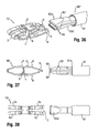
- Fig. 28a):
- shows an anterior view of the intervertebral implant inserted into the intervertebral space in the expanded condition.
- Figs. 28b) and 28c):
- show enlarged views of details of
Fig. 28a ). - Fig. 29:
- shows a lateral view of the intervertebral implant inserted into the intervertebral space in the expanded condition.
- Figs. 30 to 32:
- show a perspective view, a side view and a top view, respectively, of the intervertebral implant in the expanded condition with a second embodiment of the device for insertion.
- Figs. 33 to 35:
- show a perspective view, a side view and a top view, respectively, of the intervertebral implant in the compressed condition with the second embodiment of the device for insertion attached thereto.
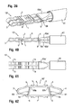
- Figs. 36 to 38:
- show a perspective view, a side view and a top view, respectively, of an intervertebral implant according to a second embodiment in the expanded condition with a device for insertion according to the third embodiment.
- Figs. 39 to 41:
- show a perspective view, a side view and a top view, respectively, of the intervertebral implant according to the second embodiment in the compressed condition with the device for insertion according to the third embodiment attached thereto.
- Fig. 42:
- shows a side view of a third embodiment of the intervertebral implant.
- As shown in
Figs. 1 to 4 , theintervertebral implant 10 according to a first embodiment is a one piece hollow body that comprises anupper wall 1, alower wall 2 andside walls lower wall 2. Thelength 1 of theupper wall 1 and thelower wall 2 is such that the intervertebral implant can be accommodated fully in the intervertebral space between two vertebrae. The width w1 of theupper wall 1 and thelower wall 2 is smaller than thelength 1. The thickness of the walls and the dimensions are such that the implant has substantially the shape of a closed loop made of a flat stripe as shown, for example, inFig. 2 . In particular, the dimensions are such that the implant comprises the ability to assume a compressed condition as shown inFigs. 1 to 4 in which the distance between the upper wall and the lower wall is smallest and defines a first height h1 of the implant and an expanded condition shown inFigs. 9 to 12 where the distance between theupper wall 1 and thelower wall 2 is greatest and defines a second height h2 of the implant. Theside walls - A plurality of
engagement portions 5 are provided at theupper wall 1 and thelower wall 2. Theengagement portions 5 are shaped as ribs with substantially sharpfree edges 5a that are bent outward into the direction of the side walls. The ribs extend across the full width of the intervertebral implant. In the embodiment shown, the ribs are arranged in groups offset from the center of the intervertebral implant in length direction. Between theside walls ribs 5, bulges 6 are provided in theupper wall 1 and thelower wall 2 that extend across the walls in width direction. Thebulges 6 have such a height in relation to theengagement portions 5 that in the compressed condition, as best shown inFig. 2 , thebulges 6 prevent an engagement of theengagement portions 5 with the end plates of the vertebrae during the insertion procedure. - The intervertebral implant further comprises two
opposite slits 7 that extend through theside walls upper wall 1 and thelower wall 2 until a distance from the center of the implant in length direction. The length of theslits 7 is greater than the distance between the slits in a top view, as seen inFig. 3 . Hence, the intervertebral implant has in a top view, as shown inFig. 3 , substantially a H-shape. By means of theslits 7 each half of the implant is bifurcated and forms first and secondupper wall portions lower wall portions Figs. 3 and 4 . - At the center of the implant in the length direction a
strut 8 is provided that has afirst end 8a and asecond end 8b. Thefirst end 8a is formed in one piece with theupper wall 1. Thesecond end 8b is free. Thestrut 8 has such a thickness in the width direction such that it is deformable. As shown inFigs. 1 and 2 , thestrut 8 is deformable in such a way that in the compressed condition of the implant as shown inFig. 8 , it contacts thelower wall 2 with a portion lying between thefirst end 8a and thesecond end 8b and defines a minimum distance of theupper wall 1 from thelower wall 2 in height direction that defines the first height h1 of the implant. Referring toFigs. 9 and 10 , in the expanded condition, the strut extends substantially vertically or at a small angle with respect to the height direction. When the implant is in the expanded condition, thefree end 8b of the strut is supported by thelower wall 2. A catch or locking ratchetingportion 20 may be provided for thestrut 8 at the inside of thelower wall 2, as shown, for example, inFig. 28c ). Such acatch 20 may be, for example, a shallow indentation or a recess that catches thefree end 8b of thestrut 8. Furthermore, aslit 8c extends from thefree end 8b through the strut in the direction to thefirst end 8a such that the strut is also bifurcated, as can be best seen inFigs. 9 and 12 . - The intervertebral implant is configured to assume two end conditions and intermediate conditions there between; the compressed condition in which the distance between the
upper wall 1 and thelower wall 2 in height direction is smallest as shown inFigs. 1 to 4 and the expanded condition as shown inFigs. 9 to 12 in which the distance between theupper wall 1 and thelower wall 2 is greatest.Figs. 5 to 8 show an intermediate condition, in which the distance between theupper wall 1 and thelower wall 2 is not yet the full distance in height direction. - Referring to
Figs. 5 to 12 , in the intermediate and the expanded condition, the distance between theupper wall 1 and thelower wall 2 increases so that the height of the implant increases. Also, theslits 7 expand to assume a V-shape with increasing width towards the side walls. This results in that theupper wall portions lower wall portions Fig. 12 , the intervertebral implant has a slight X-shape in a top view. Therefore, the width of the implant in an intermediate and in the expanded condition is increased compared to the compressed condition. Thus, the intervertebral implant is configured to expand three-dimensionally in two spatial directions. - In the expanded condition, in a side view as shown in
Fig. 10 , the portions adjacent the side walls comprise a substantially V-shaped cross section. In the center part of the implant, theupper wall 1 and thelower wall 2 have the greatest distance from each other. Thebulges 6 do no longer project above theengagement portions 5. Therefore, theengagement portions 5 project out of the upper and lower wall to be able to engage the end plates of the vertebrae. - The intervertebral implant is made of a shape-memory material. Such a shape-memory material can be, for example, a shape-memory alloy, such as certain nickel-titanium alloys that exhibit shape-memory properties, in particular Nitinol. Also, the material can be a shape-memory polymer material.
- The shape-memory effect of shape-memory material results from a phase transition within the material at a transition temperature. The intervertebral implant can be manufactures such that it assumes the pre-deformed expanded condition as shown in
Figs. 9 to 12 at approximately body temperature or at a predefined temperature below body temperature. Then, the implant is cooled down and compressed to assume the compressed condition. The compression can be performed, for example, with a device shown inFigs. 13 to 18 . Thedevice 50 for compressing the implant comprises aholder 51 that accommodates theimplant 10 and comprises asupport surface 52 for supporting, for example, theupper wall 1 of the implant. Apress plate 53 is provided that is configured to be pressed against the opposite wall, in the example shown, thelower wall 2 of the implant. The press plate comprisesprojections 54 extending towards the support surface at either end of the press plate. Theprojections 54 serve as lateral limiters that prevent further expansion in width direction of the implant during compression in height direction. An actuator for moving thepress plate 53 downward is further provided. - The compression of the implant can be made under cooling conditions to cool the implant below the transition temperature. The implant remains in the compressed condition unless it is heated above the transition temperature.
- The first embodiment of a tool for insertion of the
intervertebral implant 10 is explained with reference toFigs. 19 to 21 . Thetool 60 comprises asleeve 61 having afirst end 61a and an oppositesecond end 61b. Agrip portion 62 may be provided on the sleeve, for example, near thesecond end 61b. Within the sleeve an actuating portion (not shown) for agripper 63 is provided. Thegripper 63 extends out of the sleeve at thefirst end 61a. The gripper is fork-shaped and has twoarms Fig. 20 , in which thearms Fig. 21 , in which thearms pins 64 at the end of thearms handle 65 may be provided that is connected to the actuator. Rotation of the handle in one direction draws the gripper into thesleeve 61, as shown inFig. 20 , so that thearms Fig. 21 . The length of the arms corresponds substantially to the length of the implant in the compressed state, so that, as shown inFig. 23 , when theimplant 10 is engaged by thepins 64 at oneside wall 3, theother side wall 4 abuts against the end of the arms. - Use of the
intervertebral implant 10 will be explained with reference toFigs. 22 to 29 . As shown inFig. 22 , the intervertebral implant is in the compressed state prior to taking it up with the device forinsertion 60. As shown inFig. 23 , the implant is gripped between thearms gripper 63 such that thepins 64 engage one side of the implant and the opposite side is abutting against the bottom of the fork-shaped gripper. Hence, the intervertebral implant is firmly held with the gripper. - Then, the intervertebral implant is introduced into the intervertebral space using a lateral approach as seen in
Figs. 24 to 26 . As shown inFig. 24 , the rounded edges of thearms rounded side walls Fig. 25 , thebulges 6 in the compressed condition of the implant have the same height or are slightly higher than thecrests 5a of theengagement portions 5 so that during insertion the rounded shape of the bulges protects the vertebral end plates from being injured by theengagement portions 5. In the finally inserted state as shown inFig. 26 , theimplant 10 is held by the arms of the gripper has been fully introduced. Then, thearms gripper 63 are opened and the device for insertion is carefully removed. As best seen inFig. 27 , the implant is still in the compressed condition. By the action of the body heat, the implant begins to expand as shown inFig. 28a , thereby enlarging the intervertebral space. In the expanded condition, theengagement portions 5 engage the vertebral end plate to prevent movement of the intervertebral implant. Thestrut 8 finally extends substantially vertically and maybe caught in thecatch 20 as shown inFigs. 28b) and 28c ). In the expanded condition, the strut additionally bears the load that acts onto the upper wall and transmits it to the lower wall. During expansion, the intervertebral implant also expands in width direction, as shown inFig. 29 , thereby permitting a load transfer over a greater width which renders the implant more stable. - Referring to
Figs. 30 to 35 , a second embodiment of the device for insertion is shown. The device for insertion 60' comprises agripper 67 that has afront portion 67a from which apin 68 extends at a distance to thefront portion 67a in a direction perpendicular to a longitudinal axis A of thegripper 67. The length of thepin 68 is smaller than the width of theslits 7, as shown inFig. 32 , such that thepin 68 can be introduced into the implant and removed therefrom in the expanded condition of the implant. The distance between the outer surface of thepin 68 and the roundedfront portion 67a of thegripper 67 corresponds substantially to the thickness of theside wall Fig. 34 , the gripper can firmly hold the implant. - In use, the device for insertion 60' is coupled to the implant in the expanded condition. Then, the implant is compressed with the device for insertion attached thereto. In the compressed condition, the gripper and the implant are connected to each other. Then, the implant is inserted into the intervertebral space. After expansion of the implant, the gripper can be removed since the length of the
pin 68 is shorter than the width of theslits 7. - Referring to
Figs. 36 to 41 , a second embodiment of the intervertebral implant and a third embodiment of the device of insertion will be explained. - The intervertebral implant 10' according to the second embodiment has additionally at one side wall 3 a rib-shaped
projection 9 extending laterally away from theside wall 3. Due to theslit 7 eachupper wall portion lower wall portion lateral projection 9. The outer end of the projection has a substantially circular cross section. - The device for
insertion 60" according to the third embodiment is similar to the device forinsertion 60 according to the first embodiment in that it comprises asleeve 61 and a gripper 63' extending out from thefirst end 61a of the sleeve. The gripper 63' comprisesarms 63a', 63b' that havecylindrical recesses 69 at a distance from their free end that match the shape of thelateral projections 9 of the implant. The gripper 63' can assume an open position in which the arms have a distance from each other and that permits introduction of thelateral projection 9 of the implant. The gripper 63' can then assume a closed position as shown inFigs. 39 to 41 , in which thelateral projection 9 is gripped by the arms and firmly held in therecesses 69. The width of the gripper is such that substantially the wholelateral projection 9 in a width direction is accommodated between the arms of the gripper when the implant is in the compressed state, as shown inFig. 39 . The use of the implant and a device for insertion is similar of the use of the implant and the device in the first embodiment. The implant is taken by the device for insertion when it is in the compressed state. When the implant is introduced between two vertebrae, theopposite side wall 4 that has nolateral projection 9 is the first portion to be introduced. Due to the rounded side wall, the introduction can be carried out gently. - A third embodiment of the intervertebral implant is shown in
Fig. 42 . Theimplant 10" differs from the implants of the previous embodiments in that it comprises twostruts first end projections 5 and thebulges 6. Thesecond end 80b, 81b of thestruts depression 6a at the inside of thelower wall 2 that corresponds to thebulges 6 when the implant is in the expanded condition. In the compressed condition, the struts are deformed towards theside walls struts - Modifications of the above described embodiments are conceivable. More than two struts may be provided. The struts may have another shape that permits transmission of loads. The struts may be integrally formed with the upper or with the lower wall. More than two
slits 7 may be provided, hence giving the implant a more complex structure. For example, additional slits may be provided that allow an additional expansion. It is also conceivable that no slits are provided. In this case the expansion of the implant takes place only in one direction, for example the height direction. - The width of the upper and lower wall needs not to be constant over the length. For example, the width may be greater at one end compared to the other end.
Claims (16)
- Intervertebral implant comprising
a single piece hollow body with an upper wall (1) configured to engage a first vertebral end plate and a lower wall (2) configured to engage a second vertebral end plate, with two opposite sidewalls (3, 4) connecting the upper wall and the lower wall, respectively, and with a load transmitting part (8; 80, 81) configured to transmit load between the upper wall and the lower wall;
wherein the body is configured to assume a compressed condition in which a distance between the upper wall (1) and the lower wall (2) defines a first height (h1) of the implant and an expanded condition in which the distance between the upper wall (1) and the lower wall (2) defines a second height (h2) of the implant that is greater than the first height (h1) ; and wherein the implant is made of a material that exhibits shape memory properties. - The intervertebral implant of claim 1, wherein the load transmitting part (8; 80, 81) includes at least one strut (8; 80, 81) having a first end (8a, 80a, 81a) connected to either the upper wall (1) or the lower wall (2) and a second end (8b, 80b, 81b) and wherein the strut is deformable such that it is deformed in the compressed condition and non deformed in the expanded condition.
- The intervertebral implant of claim 2, wherein in the deformed condition, at least a portion of the strut (8; 80, 81) extends substantially parallel to the upper wall or the lower wall.
- The intervertebral implant of claim 2 or 3, wherein in the non-deformed condition, at least a portion of the strut (8; 80, 81) extends substantially perpendicular to the upper wall or the lower wall.
- The intervertebral implant of one of claims 2 to 4, wherein the second end (8b, 80b, 81b) of the strut (8; 80, 81) is free in the deformed condition.
- The intervertebral implant of one of claims 2 to 5, wherein the second end (8b, 80b, 81b) of the strut (8; 80, 81) is caught in a catch (20, 6a) in the expanded condition.
- The intervertebral implant of one of claims 2 to 6, wherein the strut (8; 80, 81) extends across substantially the whole width of the upper wall (1) or the lower wall (2).
- The intervertebral implant of one of claims 1 to 7 wherein a shape of the implant (10, 10', 10") in the expanded condition is pre-formed and wherein the shape of the implant (10, 10', 10") in the compressed condition is achieved by deforming the pre-formed implant at a temperature below a transition temperature of the material.
- The intervertebral implant of one of claims 1 to 8, wherein the upper wall (1), the lower wall (2) and the side walls (3,4) form a closed loop.
- The intervertebral implant of one of claims 1 to 9, wherein a width of the upper wall or the lower wall in the compressed condition defines a first width w1 of the implant and wherein a width of the upper wall or the lower wall in the expanded condition defines a second width w2 of the implant, the second width w2 being greater than the first width.
- The intervertebral implant of one of claims 1 to 10, wherein at least one slit (7) is provided extending completely through the side wall (3, 4) into the upper wall (1) and the lower wall (2) and wherein a width of the slit (7) is substantially the same in the compressed condition and increases towards the sidewalls in the expanded condition.
- The intervertebral implant of claim 11, wherein two slits (7) are provided that extend opposite to each other from the sidewalls (3, 4) towards the center of the upper wall (1) and the lower wall (2) and wherein a length of the slits is larger than a greatest width of the slits.
- The intervertebral implant of one of claims 1 to 12, wherein at least one of the sidewalls (3, 4) is rounded towards the outside.
- The intervertebral implant of one of claims 1 to 13, wherein the upper wall (1) and the lower wall (2) comprise projections (5), such as teeth, configured to engage the vertebral end plate and wherein the upper wall (1) and the lower wall (2) comprise bulges (6) rounded towards the outside that are arranged between the sidewalls (3, 4) and the projections (5), the bulges projecting farther out than the projections or are at equal height in the compressed condition.
- The intervertebral implant of one of claims 1 to 13, further comprising a projection (9) extending laterally from at least one of the side walls (3, 4) for engagement with an insertion device.
- The intervertebral implant of one of claims 1 to 15, wherein the implant (10, 10', 10") has in a top or a bottom view a substantially H-shaped contour in the compressed condition and a substantially X-shaped contour in the expanded condition.
Priority Applications (5)
| Application Number | Priority Date | Filing Date | Title |
|---|---|---|---|
| EP11195380.8A EP2606860B1 (en) | 2011-12-22 | 2011-12-22 | Expandable intervertebral implant |
| JP2012276791A JP6099962B2 (en) | 2011-12-22 | 2012-12-19 | Intervertebral implant |
| CN201210554624.9A CN103169552B (en) | 2011-12-22 | 2012-12-19 | Intervertebral implant |
| KR1020120150882A KR20130079206A (en) | 2011-12-22 | 2012-12-21 | Intervertebral implant |
| US13/725,221 US9387093B2 (en) | 2011-12-22 | 2012-12-21 | Intervertebral implant |
Applications Claiming Priority (1)
| Application Number | Priority Date | Filing Date | Title |
|---|---|---|---|
| EP11195380.8A EP2606860B1 (en) | 2011-12-22 | 2011-12-22 | Expandable intervertebral implant |
Publications (2)
| Publication Number | Publication Date |
|---|---|
| EP2606860A1 true EP2606860A1 (en) | 2013-06-26 |
| EP2606860B1 EP2606860B1 (en) | 2016-07-20 |
Family
ID=45406524
Family Applications (1)
| Application Number | Title | Priority Date | Filing Date |
|---|---|---|---|
| EP11195380.8A Active EP2606860B1 (en) | 2011-12-22 | 2011-12-22 | Expandable intervertebral implant |
Country Status (5)
| Country | Link |
|---|---|
| US (1) | US9387093B2 (en) |
| EP (1) | EP2606860B1 (en) |
| JP (1) | JP6099962B2 (en) |
| KR (1) | KR20130079206A (en) |
| CN (1) | CN103169552B (en) |
Families Citing this family (14)
| Publication number | Priority date | Publication date | Assignee | Title |
|---|---|---|---|---|
| WO2012009152A1 (en) | 2010-07-15 | 2012-01-19 | Hugues Malandain | A plastically deformable inter-osseous device |
| EP2688519B1 (en) * | 2011-03-23 | 2020-01-01 | Alphatec Spine, Inc. | Expandable interbody spacer |
| US8696752B2 (en) * | 2011-12-30 | 2014-04-15 | Metal Industries Research & Development Centre | Interbody cage for spine fusion |
| US10039650B2 (en) * | 2013-03-15 | 2018-08-07 | In Queue Innovations, Llc | Expandable fusion cage system |
| US9615935B2 (en) * | 2014-01-30 | 2017-04-11 | Titan Spine, Llc | Thermally activated shape memory spring assemblies for implant expansion |
| US9498266B2 (en) * | 2014-02-12 | 2016-11-22 | Wright Medical Technology, Inc. | Intramedullary implant, system, and method for inserting an implant into a bone |
| CN105310803B (en) * | 2014-07-27 | 2018-11-23 | 温州医科大学附属第二医院、温州医科大学附属育英儿童医院 | A kind of embedded with minimal invasion shape memory Invasive lumbar fusion device |
| WO2016179555A1 (en) * | 2015-05-07 | 2016-11-10 | Meditech Spine, Llc | Inter-vertebral implant for spinal fusion |
| EP3103417B1 (en) * | 2015-06-10 | 2018-01-31 | Biedermann Technologies GmbH & Co. KG | Intervertebral implant and system of an intervertebral implant and an instrument for inserting the intervertebral implant |
| FR3041246B1 (en) * | 2015-09-17 | 2017-10-27 | Spineway | SURGICAL ASSEMBLY FOR ESTABLISHING A PROSTHESIS DISCALE |
| FR3058044A1 (en) * | 2016-10-27 | 2018-05-04 | Ldr Medical | EXPANDABLE INTERSOMATIC CAGE |
| FR3058043B1 (en) * | 2016-10-27 | 2020-11-13 | Ldr Medical | EXPANDABLE INTERSOMATIC CAGE |
| US10842487B2 (en) * | 2017-10-20 | 2020-11-24 | Biomedical Enterprises, Inc. | Method and apparatus for loading and implanting a shape memory implant |
| DE102020102100A1 (en) | 2020-01-29 | 2021-07-29 | Joline Gmbh & Co. Kg | Erecting device, insertion device with an erecting device and method for straightening and stabilizing the spine |
Citations (10)
| Publication number | Priority date | Publication date | Assignee | Title |
|---|---|---|---|---|
| WO1998014142A1 (en) * | 1996-10-01 | 1998-04-09 | Surgical Dynamics, Inc. | Spinal fusion implant and method of insertion thereof |
| WO2001001895A1 (en) * | 1999-07-02 | 2001-01-11 | Petrus Besselink | Reinforced expandable cage |
| US20030105631A1 (en) | 2001-12-03 | 2003-06-05 | Habte Yosef G. | Method for generating transcribed data from verbal information and providing multiple recipients with access to the transcribed data |
| EP1552797A2 (en) * | 1999-01-27 | 2005-07-13 | Disc-O-Tech Medical Technologies, Ltd. | Expandable intervertebral spacer |
| WO2006116761A2 (en) * | 2005-04-27 | 2006-11-02 | Stout Medical Group, L.P. | Expandable support device and methods of use |
| WO2007009107A2 (en) * | 2005-07-14 | 2007-01-18 | Stout Medical Group, P.L. | Expandable support device and method of use |
| US20070219634A1 (en) * | 2004-09-21 | 2007-09-20 | Greenhalgh E S | Expandable support device and method of use |
| US20090076613A1 (en) | 2007-07-26 | 2009-03-19 | Lutz Biedermann | Intervertebral disc prosthesis |
| US20090163918A1 (en) * | 2004-04-05 | 2009-06-25 | Mark M Levy | Expandable bone device |
| US20090222100A1 (en) * | 2008-02-28 | 2009-09-03 | Stryker Spine | Tool for implanting expandable intervertebral implant |
Family Cites Families (19)
| Publication number | Priority date | Publication date | Assignee | Title |
|---|---|---|---|---|
| FR2715293B1 (en) * | 1994-01-26 | 1996-03-22 | Biomat | Vertebral interbody fusion cage. |
| FR2728159B1 (en) * | 1994-12-16 | 1997-06-27 | Tornier Sa | ELASTIC DISC PROSTHESIS |
| US6143031A (en) * | 1995-10-20 | 2000-11-07 | Synthes (U.S.A.) | Intervertebral implant with compressible shaped hollow element |
| US6193757B1 (en) * | 1998-10-29 | 2001-02-27 | Sdgi Holdings, Inc. | Expandable intervertebral spacers |
| NL1018438C1 (en) * | 2001-07-02 | 2003-01-08 | Baat Medical Engineering B V | Foldable and foldable tools for placement in a spine. |
| US20030195631A1 (en) | 2002-04-12 | 2003-10-16 | Ferree Bret A. | Shape-memory spacers for artificial disc replacements |
| US20050222683A1 (en) | 2004-03-31 | 2005-10-06 | Sdgi Holdings | Shape memory alloy disc replacement device |
| FR2871366A1 (en) * | 2004-06-09 | 2005-12-16 | Ceravic Soc Par Actions Simpli | PROSTHETIC EXPANSIBLE BONE IMPLANT |
| US7678148B2 (en) * | 2004-07-23 | 2010-03-16 | Warsaw Orthopedic, Inc. | Expandable spinal implant having interlocking geometry for structural support |
| US20060241757A1 (en) * | 2005-03-31 | 2006-10-26 | Sdgi Holdings, Inc. | Intervertebral prosthetic device for spinal stabilization and method of manufacturing same |
| US7655043B2 (en) * | 2005-04-29 | 2010-02-02 | Warsaw Orthopedic, Inc. | Expandable spinal implant and associated instrumentation |
| WO2007076377A2 (en) * | 2005-12-19 | 2007-07-05 | Stout Medical Group, L.P. | Expandable support device |
| US20070179611A1 (en) | 2005-12-22 | 2007-08-02 | Dipoto Gene P | Methods and devices for replacement of intervertebral discs |
| GB0605960D0 (en) * | 2006-03-24 | 2006-05-03 | Galley Geoffrey H | Expandable spinal prosthesis |
| US20080167686A1 (en) * | 2007-01-05 | 2008-07-10 | Warsaw Orthopedic, Inc. | Non-Rigid Intervertebral Spacers |
| EP2189124A1 (en) * | 2008-11-19 | 2010-05-26 | Christian Röbling | Thorn removal set implant |
| CN102369332B (en) * | 2008-12-31 | 2014-07-02 | 奥马尔·F·希门尼斯 | Flexible joint arrangement incorporating flexure members |
| JP2012513882A (en) * | 2008-12-31 | 2012-06-21 | エフ. ヒメネス、オマール | Vertebral distraction and fusion method and apparatus using flexure members |
| WO2012009152A1 (en) * | 2010-07-15 | 2012-01-19 | Hugues Malandain | A plastically deformable inter-osseous device |
-
2011
- 2011-12-22 EP EP11195380.8A patent/EP2606860B1/en active Active
-
2012
- 2012-12-19 JP JP2012276791A patent/JP6099962B2/en not_active Expired - Fee Related
- 2012-12-19 CN CN201210554624.9A patent/CN103169552B/en not_active Expired - Fee Related
- 2012-12-21 US US13/725,221 patent/US9387093B2/en active Active
- 2012-12-21 KR KR1020120150882A patent/KR20130079206A/en not_active Application Discontinuation
Patent Citations (10)
| Publication number | Priority date | Publication date | Assignee | Title |
|---|---|---|---|---|
| WO1998014142A1 (en) * | 1996-10-01 | 1998-04-09 | Surgical Dynamics, Inc. | Spinal fusion implant and method of insertion thereof |
| EP1552797A2 (en) * | 1999-01-27 | 2005-07-13 | Disc-O-Tech Medical Technologies, Ltd. | Expandable intervertebral spacer |
| WO2001001895A1 (en) * | 1999-07-02 | 2001-01-11 | Petrus Besselink | Reinforced expandable cage |
| US20030105631A1 (en) | 2001-12-03 | 2003-06-05 | Habte Yosef G. | Method for generating transcribed data from verbal information and providing multiple recipients with access to the transcribed data |
| US20090163918A1 (en) * | 2004-04-05 | 2009-06-25 | Mark M Levy | Expandable bone device |
| US20070219634A1 (en) * | 2004-09-21 | 2007-09-20 | Greenhalgh E S | Expandable support device and method of use |
| WO2006116761A2 (en) * | 2005-04-27 | 2006-11-02 | Stout Medical Group, L.P. | Expandable support device and methods of use |
| WO2007009107A2 (en) * | 2005-07-14 | 2007-01-18 | Stout Medical Group, P.L. | Expandable support device and method of use |
| US20090076613A1 (en) | 2007-07-26 | 2009-03-19 | Lutz Biedermann | Intervertebral disc prosthesis |
| US20090222100A1 (en) * | 2008-02-28 | 2009-09-03 | Stryker Spine | Tool for implanting expandable intervertebral implant |
Also Published As
| Publication number | Publication date |
|---|---|
| CN103169552B (en) | 2016-12-28 |
| CN103169552A (en) | 2013-06-26 |
| JP2013132557A (en) | 2013-07-08 |
| JP6099962B2 (en) | 2017-03-22 |
| EP2606860B1 (en) | 2016-07-20 |
| US20130166030A1 (en) | 2013-06-27 |
| US9387093B2 (en) | 2016-07-12 |
| KR20130079206A (en) | 2013-07-10 |
Similar Documents
| Publication | Publication Date | Title |
|---|---|---|
| EP2606860B1 (en) | Expandable intervertebral implant | |
| US10624756B2 (en) | Expansible intersomatic cage | |
| JP6846124B2 (en) | Facet implants and facet implant systems | |
| AU2015378534B2 (en) | Unitarily formed expandable spinal implant and method of manufacturing and implanting same | |
| EP3166522B1 (en) | Bone implant and means of insertion | |
| US6488710B2 (en) | Reinforced expandable cage and method of deploying | |
| JP6243937B2 (en) | Surgical graft with guide rail | |
| EP3095393B1 (en) | Surgical staple and instrument for holding and implanting the surgical staple | |
| US20190336300A1 (en) | Expansible intersomatic cage | |
| US20170209193A1 (en) | Bone implant with means for multi directional force and means of insertion | |
| EP1572041B1 (en) | Intervertebral implant and insertion tool for inserting same | |
| WO2021127635A1 (en) | Expandable intervertebral implant | |
| JP2016526455A5 (en) | ||
| US20050288788A1 (en) | Intervertebral implant and associated method | |
| US20170000482A1 (en) | Surgical instrument for fitting an osteosynthesis clip | |
| US20080114454A1 (en) | Expandable Vertebral Body Implants Including Shape-Memory Materials and Methods of Use | |
| JP2003505149A (en) | Improved spinal implants and inserts | |
| KR20140080501A (en) | Expandable inter-vertebral cage and method of installing same | |
| AU2013357235B2 (en) | Intervertebral cage expandable step-by-step | |
| WO2008112607A2 (en) | Spinal implant | |
| US10010429B2 (en) | Intervertebral cage which is expandable in steps and implantation instrument therefor | |
| TW201328655A (en) | Intervertebral implant | |
| WO2023114718A2 (en) | Expandable compliant spinal fusion cage |
Legal Events
| Date | Code | Title | Description |
|---|---|---|---|
| 17P | Request for examination filed |
Effective date: 20130513 |
|
| AK | Designated contracting states |
Kind code of ref document: A1 Designated state(s): AL AT BE BG CH CY CZ DE DK EE ES FI FR GB GR HR HU IE IS IT LI LT LU LV MC MK MT NL NO PL PT RO RS SE SI SK SM TR |
|
| AX | Request for extension of the european patent |
Extension state: BA ME |
|
| PUAI | Public reference made under article 153(3) epc to a published international application that has entered the european phase |
Free format text: ORIGINAL CODE: 0009012 |
|
| 17Q | First examination report despatched |
Effective date: 20150416 |
|
| GRAP | Despatch of communication of intention to grant a patent |
Free format text: ORIGINAL CODE: EPIDOSNIGR1 |
|
| INTG | Intention to grant announced |
Effective date: 20160127 |
|
| GRAS | Grant fee paid |
Free format text: ORIGINAL CODE: EPIDOSNIGR3 |
|
| GRAA | (expected) grant |
Free format text: ORIGINAL CODE: 0009210 |
|
| AK | Designated contracting states |
Kind code of ref document: B1 Designated state(s): AL AT BE BG CH CY CZ DE DK EE ES FI FR GB GR HR HU IE IS IT LI LT LU LV MC MK MT NL NO PL PT RO RS SE SI SK SM TR |
|
| REG | Reference to a national code |
Ref country code: GB Ref legal event code: FG4D |
|
| REG | Reference to a national code |
Ref country code: CH Ref legal event code: NV Representative=s name: NOVAGRAAF INTERNATIONAL SA, CH Ref country code: CH Ref legal event code: EP |
|
| REG | Reference to a national code |
Ref country code: IE Ref legal event code: FG4D |
|
| REG | Reference to a national code |
Ref country code: AT Ref legal event code: REF Ref document number: 813401 Country of ref document: AT Kind code of ref document: T Effective date: 20160815 |
|
| REG | Reference to a national code |
Ref country code: DE Ref legal event code: R096 Ref document number: 602011028295 Country of ref document: DE |
|
| REG | Reference to a national code |
Ref country code: LT Ref legal event code: MG4D |
|
| REG | Reference to a national code |
Ref country code: NL Ref legal event code: MP Effective date: 20160720 |
|
| REG | Reference to a national code |
Ref country code: AT Ref legal event code: MK05 Ref document number: 813401 Country of ref document: AT Kind code of ref document: T Effective date: 20160720 |
|
| PG25 | Lapsed in a contracting state [announced via postgrant information from national office to epo] |
Ref country code: NL Free format text: LAPSE BECAUSE OF FAILURE TO SUBMIT A TRANSLATION OF THE DESCRIPTION OR TO PAY THE FEE WITHIN THE PRESCRIBED TIME-LIMIT Effective date: 20160720 Ref country code: RS Free format text: LAPSE BECAUSE OF FAILURE TO SUBMIT A TRANSLATION OF THE DESCRIPTION OR TO PAY THE FEE WITHIN THE PRESCRIBED TIME-LIMIT Effective date: 20160720 Ref country code: IS Free format text: LAPSE BECAUSE OF FAILURE TO SUBMIT A TRANSLATION OF THE DESCRIPTION OR TO PAY THE FEE WITHIN THE PRESCRIBED TIME-LIMIT Effective date: 20161120 Ref country code: LT Free format text: LAPSE BECAUSE OF FAILURE TO SUBMIT A TRANSLATION OF THE DESCRIPTION OR TO PAY THE FEE WITHIN THE PRESCRIBED TIME-LIMIT Effective date: 20160720 Ref country code: FI Free format text: LAPSE BECAUSE OF FAILURE TO SUBMIT A TRANSLATION OF THE DESCRIPTION OR TO PAY THE FEE WITHIN THE PRESCRIBED TIME-LIMIT Effective date: 20160720 Ref country code: NO Free format text: LAPSE BECAUSE OF FAILURE TO SUBMIT A TRANSLATION OF THE DESCRIPTION OR TO PAY THE FEE WITHIN THE PRESCRIBED TIME-LIMIT Effective date: 20161020 Ref country code: IT Free format text: LAPSE BECAUSE OF FAILURE TO SUBMIT A TRANSLATION OF THE DESCRIPTION OR TO PAY THE FEE WITHIN THE PRESCRIBED TIME-LIMIT Effective date: 20160720 Ref country code: HR Free format text: LAPSE BECAUSE OF FAILURE TO SUBMIT A TRANSLATION OF THE DESCRIPTION OR TO PAY THE FEE WITHIN THE PRESCRIBED TIME-LIMIT Effective date: 20160720 |
|
| PG25 | Lapsed in a contracting state [announced via postgrant information from national office to epo] |
Ref country code: BE Free format text: LAPSE BECAUSE OF FAILURE TO SUBMIT A TRANSLATION OF THE DESCRIPTION OR TO PAY THE FEE WITHIN THE PRESCRIBED TIME-LIMIT Effective date: 20160720 Ref country code: GR Free format text: LAPSE BECAUSE OF FAILURE TO SUBMIT A TRANSLATION OF THE DESCRIPTION OR TO PAY THE FEE WITHIN THE PRESCRIBED TIME-LIMIT Effective date: 20161021 Ref country code: PL Free format text: LAPSE BECAUSE OF FAILURE TO SUBMIT A TRANSLATION OF THE DESCRIPTION OR TO PAY THE FEE WITHIN THE PRESCRIBED TIME-LIMIT Effective date: 20160720 Ref country code: SE Free format text: LAPSE BECAUSE OF FAILURE TO SUBMIT A TRANSLATION OF THE DESCRIPTION OR TO PAY THE FEE WITHIN THE PRESCRIBED TIME-LIMIT Effective date: 20160720 Ref country code: ES Free format text: LAPSE BECAUSE OF FAILURE TO SUBMIT A TRANSLATION OF THE DESCRIPTION OR TO PAY THE FEE WITHIN THE PRESCRIBED TIME-LIMIT Effective date: 20160720 Ref country code: LV Free format text: LAPSE BECAUSE OF FAILURE TO SUBMIT A TRANSLATION OF THE DESCRIPTION OR TO PAY THE FEE WITHIN THE PRESCRIBED TIME-LIMIT Effective date: 20160720 Ref country code: PT Free format text: LAPSE BECAUSE OF FAILURE TO SUBMIT A TRANSLATION OF THE DESCRIPTION OR TO PAY THE FEE WITHIN THE PRESCRIBED TIME-LIMIT Effective date: 20161121 Ref country code: AT Free format text: LAPSE BECAUSE OF FAILURE TO SUBMIT A TRANSLATION OF THE DESCRIPTION OR TO PAY THE FEE WITHIN THE PRESCRIBED TIME-LIMIT Effective date: 20160720 |
|
| REG | Reference to a national code |
Ref country code: DE Ref legal event code: R097 Ref document number: 602011028295 Country of ref document: DE |
|
| PG25 | Lapsed in a contracting state [announced via postgrant information from national office to epo] |
Ref country code: EE Free format text: LAPSE BECAUSE OF FAILURE TO SUBMIT A TRANSLATION OF THE DESCRIPTION OR TO PAY THE FEE WITHIN THE PRESCRIBED TIME-LIMIT Effective date: 20160720 Ref country code: RO Free format text: LAPSE BECAUSE OF FAILURE TO SUBMIT A TRANSLATION OF THE DESCRIPTION OR TO PAY THE FEE WITHIN THE PRESCRIBED TIME-LIMIT Effective date: 20160720 |
|
| PLBE | No opposition filed within time limit |
Free format text: ORIGINAL CODE: 0009261 |
|
| STAA | Information on the status of an ep patent application or granted ep patent |
Free format text: STATUS: NO OPPOSITION FILED WITHIN TIME LIMIT |
|
| PG25 | Lapsed in a contracting state [announced via postgrant information from national office to epo] |
Ref country code: SK Free format text: LAPSE BECAUSE OF FAILURE TO SUBMIT A TRANSLATION OF THE DESCRIPTION OR TO PAY THE FEE WITHIN THE PRESCRIBED TIME-LIMIT Effective date: 20160720 Ref country code: DK Free format text: LAPSE BECAUSE OF FAILURE TO SUBMIT A TRANSLATION OF THE DESCRIPTION OR TO PAY THE FEE WITHIN THE PRESCRIBED TIME-LIMIT Effective date: 20160720 Ref country code: CZ Free format text: LAPSE BECAUSE OF FAILURE TO SUBMIT A TRANSLATION OF THE DESCRIPTION OR TO PAY THE FEE WITHIN THE PRESCRIBED TIME-LIMIT Effective date: 20160720 Ref country code: BG Free format text: LAPSE BECAUSE OF FAILURE TO SUBMIT A TRANSLATION OF THE DESCRIPTION OR TO PAY THE FEE WITHIN THE PRESCRIBED TIME-LIMIT Effective date: 20161020 Ref country code: SM Free format text: LAPSE BECAUSE OF FAILURE TO SUBMIT A TRANSLATION OF THE DESCRIPTION OR TO PAY THE FEE WITHIN THE PRESCRIBED TIME-LIMIT Effective date: 20160720 |
|
| 26N | No opposition filed |
Effective date: 20170421 |
|
| PG25 | Lapsed in a contracting state [announced via postgrant information from national office to epo] |
Ref country code: SI Free format text: LAPSE BECAUSE OF FAILURE TO SUBMIT A TRANSLATION OF THE DESCRIPTION OR TO PAY THE FEE WITHIN THE PRESCRIBED TIME-LIMIT Effective date: 20160720 |
|
| PG25 | Lapsed in a contracting state [announced via postgrant information from national office to epo] |
Ref country code: MC Free format text: LAPSE BECAUSE OF FAILURE TO SUBMIT A TRANSLATION OF THE DESCRIPTION OR TO PAY THE FEE WITHIN THE PRESCRIBED TIME-LIMIT Effective date: 20160720 |
|
| REG | Reference to a national code |
Ref country code: FR Ref legal event code: ST Effective date: 20170831 |
|
| REG | Reference to a national code |
Ref country code: IE Ref legal event code: MM4A |
|
| PG25 | Lapsed in a contracting state [announced via postgrant information from national office to epo] |
Ref country code: FR Free format text: LAPSE BECAUSE OF NON-PAYMENT OF DUE FEES Effective date: 20170102 Ref country code: LU Free format text: LAPSE BECAUSE OF NON-PAYMENT OF DUE FEES Effective date: 20161222 |
|
| PG25 | Lapsed in a contracting state [announced via postgrant information from national office to epo] |
Ref country code: IE Free format text: LAPSE BECAUSE OF NON-PAYMENT OF DUE FEES Effective date: 20161222 |
|
| PG25 | Lapsed in a contracting state [announced via postgrant information from national office to epo] |
Ref country code: CY Free format text: LAPSE BECAUSE OF FAILURE TO SUBMIT A TRANSLATION OF THE DESCRIPTION OR TO PAY THE FEE WITHIN THE PRESCRIBED TIME-LIMIT Effective date: 20160720 Ref country code: HU Free format text: LAPSE BECAUSE OF FAILURE TO SUBMIT A TRANSLATION OF THE DESCRIPTION OR TO PAY THE FEE WITHIN THE PRESCRIBED TIME-LIMIT; INVALID AB INITIO Effective date: 20111222 |
|
| PG25 | Lapsed in a contracting state [announced via postgrant information from national office to epo] |
Ref country code: MK Free format text: LAPSE BECAUSE OF FAILURE TO SUBMIT A TRANSLATION OF THE DESCRIPTION OR TO PAY THE FEE WITHIN THE PRESCRIBED TIME-LIMIT Effective date: 20160720 Ref country code: TR Free format text: LAPSE BECAUSE OF FAILURE TO SUBMIT A TRANSLATION OF THE DESCRIPTION OR TO PAY THE FEE WITHIN THE PRESCRIBED TIME-LIMIT Effective date: 20160720 |
|
| PG25 | Lapsed in a contracting state [announced via postgrant information from national office to epo] |
Ref country code: MT Free format text: LAPSE BECAUSE OF NON-PAYMENT OF DUE FEES Effective date: 20161222 |
|
| PG25 | Lapsed in a contracting state [announced via postgrant information from national office to epo] |
Ref country code: AL Free format text: LAPSE BECAUSE OF FAILURE TO SUBMIT A TRANSLATION OF THE DESCRIPTION OR TO PAY THE FEE WITHIN THE PRESCRIBED TIME-LIMIT Effective date: 20160720 |
|
| PGFP | Annual fee paid to national office [announced via postgrant information from national office to epo] |
Ref country code: GB Payment date: 20221223 Year of fee payment: 12 |
|
| PGFP | Annual fee paid to national office [announced via postgrant information from national office to epo] |
Ref country code: CH Payment date: 20230104 Year of fee payment: 12 |
|
| PGFP | Annual fee paid to national office [announced via postgrant information from national office to epo] |
Ref country code: DE Payment date: 20221227 Year of fee payment: 12 |
|
| P01 | Opt-out of the competence of the unified patent court (upc) registered |
Effective date: 20230525 |