EP2604340A1 - Gasoline sulfur reductions catalyst for fluid catalytic cracking process - Google Patents
Gasoline sulfur reductions catalyst for fluid catalytic cracking process Download PDFInfo
- Publication number
- EP2604340A1 EP2604340A1 EP13158629.9A EP13158629A EP2604340A1 EP 2604340 A1 EP2604340 A1 EP 2604340A1 EP 13158629 A EP13158629 A EP 13158629A EP 2604340 A1 EP2604340 A1 EP 2604340A1
- Authority
- EP
- European Patent Office
- Prior art keywords
- catalyst
- sulfur
- zeolite
- cracking
- yttrium
- Prior art date
- Legal status (The legal status is an assumption and is not a legal conclusion. Google has not performed a legal analysis and makes no representation as to the accuracy of the status listed.)
- Granted
Links
- 239000003054 catalyst Substances 0.000 title claims abstract description 351
- NINIDFKCEFEMDL-UHFFFAOYSA-N Sulfur Chemical compound [S] NINIDFKCEFEMDL-UHFFFAOYSA-N 0.000 title claims abstract description 205
- 229910052717 sulfur Inorganic materials 0.000 title claims abstract description 205
- 239000011593 sulfur Substances 0.000 title claims abstract description 205
- 238000000034 method Methods 0.000 title claims abstract description 91
- 230000008569 process Effects 0.000 title claims abstract description 53
- 230000009467 reduction Effects 0.000 title claims description 65
- 238000004231 fluid catalytic cracking Methods 0.000 title claims description 9
- 239000010457 zeolite Substances 0.000 claims abstract description 134
- HNPSIPDUKPIQMN-UHFFFAOYSA-N dioxosilane;oxo(oxoalumanyloxy)alumane Chemical compound O=[Si]=O.O=[Al]O[Al]=O HNPSIPDUKPIQMN-UHFFFAOYSA-N 0.000 claims abstract description 117
- 229910021536 Zeolite Inorganic materials 0.000 claims abstract description 113
- 239000000203 mixture Substances 0.000 claims abstract description 85
- 229910052727 yttrium Inorganic materials 0.000 claims abstract description 84
- VWQVUPCCIRVNHF-UHFFFAOYSA-N yttrium atom Chemical compound [Y] VWQVUPCCIRVNHF-UHFFFAOYSA-N 0.000 claims abstract description 82
- 239000011159 matrix material Substances 0.000 claims abstract description 22
- 238000004523 catalytic cracking Methods 0.000 claims abstract description 20
- 239000011777 magnesium Substances 0.000 claims abstract description 20
- 229910052749 magnesium Inorganic materials 0.000 claims abstract description 20
- FYYHWMGAXLPEAU-UHFFFAOYSA-N Magnesium Chemical compound [Mg] FYYHWMGAXLPEAU-UHFFFAOYSA-N 0.000 claims abstract description 18
- 150000001768 cations Chemical group 0.000 claims abstract description 17
- 239000011148 porous material Substances 0.000 claims abstract description 11
- 238000005336 cracking Methods 0.000 claims description 69
- 229910052761 rare earth metal Inorganic materials 0.000 claims description 41
- 239000002245 particle Substances 0.000 claims description 39
- 150000002910 rare earth metals Chemical class 0.000 claims description 38
- 229930195733 hydrocarbon Natural products 0.000 claims description 30
- 150000002430 hydrocarbons Chemical class 0.000 claims description 30
- PNEYBMLMFCGWSK-UHFFFAOYSA-N aluminium oxide Inorganic materials [O-2].[O-2].[O-2].[Al+3].[Al+3] PNEYBMLMFCGWSK-UHFFFAOYSA-N 0.000 claims description 23
- 239000004927 clay Substances 0.000 claims description 21
- 239000004215 Carbon black (E152) Substances 0.000 claims description 20
- 239000011230 binding agent Substances 0.000 claims description 15
- 239000000571 coke Substances 0.000 claims description 13
- 239000007788 liquid Substances 0.000 claims description 12
- MRELNEQAGSRDBK-UHFFFAOYSA-N lanthanum(3+);oxygen(2-) Chemical compound [O-2].[O-2].[O-2].[La+3].[La+3] MRELNEQAGSRDBK-UHFFFAOYSA-N 0.000 claims description 10
- 239000007789 gas Substances 0.000 claims description 9
- WPBNNNQJVZRUHP-UHFFFAOYSA-L manganese(2+);methyl n-[[2-(methoxycarbonylcarbamothioylamino)phenyl]carbamothioyl]carbamate;n-[2-(sulfidocarbothioylamino)ethyl]carbamodithioate Chemical compound [Mn+2].[S-]C(=S)NCCNC([S-])=S.COC(=O)NC(=S)NC1=CC=CC=C1NC(=S)NC(=O)OC WPBNNNQJVZRUHP-UHFFFAOYSA-L 0.000 claims description 9
- 239000012808 vapor phase Substances 0.000 claims description 9
- 150000002898 organic sulfur compounds Chemical class 0.000 claims description 8
- 239000003208 petroleum Substances 0.000 claims description 8
- 239000007787 solid Substances 0.000 claims description 8
- 239000012071 phase Substances 0.000 claims description 7
- CETPSERCERDGAM-UHFFFAOYSA-N ceric oxide Chemical compound O=[Ce]=O CETPSERCERDGAM-UHFFFAOYSA-N 0.000 claims description 5
- 229910000422 cerium(IV) oxide Inorganic materials 0.000 claims description 5
- 125000004122 cyclic group Chemical group 0.000 claims description 5
- QVGXLLKOCUKJST-UHFFFAOYSA-N atomic oxygen Chemical compound [O] QVGXLLKOCUKJST-UHFFFAOYSA-N 0.000 claims description 3
- 238000007599 discharging Methods 0.000 claims description 3
- 229910052760 oxygen Inorganic materials 0.000 claims description 3
- 239000001301 oxygen Substances 0.000 claims description 3
- 238000004064 recycling Methods 0.000 claims description 3
- 230000001172 regenerating effect Effects 0.000 claims description 3
- 239000011572 manganese Substances 0.000 abstract description 11
- 229910052748 manganese Inorganic materials 0.000 abstract description 11
- PWHULOQIROXLJO-UHFFFAOYSA-N Manganese Chemical compound [Mn] PWHULOQIROXLJO-UHFFFAOYSA-N 0.000 abstract description 9
- 238000005504 petroleum refining Methods 0.000 abstract description 2
- 239000000047 product Substances 0.000 description 73
- 239000011701 zinc Substances 0.000 description 57
- 229910052725 zinc Inorganic materials 0.000 description 44
- HCHKCACWOHOZIP-UHFFFAOYSA-N Zinc Chemical compound [Zn] HCHKCACWOHOZIP-UHFFFAOYSA-N 0.000 description 42
- 238000006243 chemical reaction Methods 0.000 description 28
- 239000007921 spray Substances 0.000 description 26
- 239000000243 solution Substances 0.000 description 23
- YTPLMLYBLZKORZ-UHFFFAOYSA-N Thiophene Chemical compound C=1C=CSC=1 YTPLMLYBLZKORZ-UHFFFAOYSA-N 0.000 description 22
- FCEHBMOGCRZNNI-UHFFFAOYSA-N 1-benzothiophene Chemical class C1=CC=C2SC=CC2=C1 FCEHBMOGCRZNNI-UHFFFAOYSA-N 0.000 description 21
- VYPSYNLAJGMNEJ-UHFFFAOYSA-N Silicium dioxide Chemical compound O=[Si]=O VYPSYNLAJGMNEJ-UHFFFAOYSA-N 0.000 description 21
- RMVRSNDYEFQCLF-UHFFFAOYSA-N thiophenol Chemical compound SC1=CC=CC=C1 RMVRSNDYEFQCLF-UHFFFAOYSA-N 0.000 description 21
- 229910052570 clay Inorganic materials 0.000 description 20
- KKCBUQHMOMHUOY-UHFFFAOYSA-N Na2O Inorganic materials [O-2].[Na+].[Na+] KKCBUQHMOMHUOY-UHFFFAOYSA-N 0.000 description 19
- 230000009849 deactivation Effects 0.000 description 19
- 239000000654 additive Substances 0.000 description 18
- 230000000694 effects Effects 0.000 description 16
- 238000001354 calcination Methods 0.000 description 15
- 239000000463 material Substances 0.000 description 15
- 229930192474 thiophene Natural products 0.000 description 15
- 239000000126 substance Substances 0.000 description 14
- 229910052782 aluminium Inorganic materials 0.000 description 13
- XAGFODPZIPBFFR-UHFFFAOYSA-N aluminium Chemical compound [Al] XAGFODPZIPBFFR-UHFFFAOYSA-N 0.000 description 13
- 239000002841 Lewis acid Substances 0.000 description 11
- 239000001257 hydrogen Substances 0.000 description 11
- 229910052739 hydrogen Inorganic materials 0.000 description 11
- 150000007517 lewis acids Chemical class 0.000 description 11
- 239000003921 oil Substances 0.000 description 11
- 238000005342 ion exchange Methods 0.000 description 10
- 230000014759 maintenance of location Effects 0.000 description 10
- 239000000377 silicon dioxide Substances 0.000 description 10
- -1 zinc-based compounds Chemical class 0.000 description 10
- 229910001404 rare earth metal oxide Inorganic materials 0.000 description 9
- 239000002002 slurry Substances 0.000 description 9
- 239000011592 zinc chloride Substances 0.000 description 9
- JIAARYAFYJHUJI-UHFFFAOYSA-L zinc dichloride Chemical compound [Cl-].[Cl-].[Zn+2] JIAARYAFYJHUJI-UHFFFAOYSA-L 0.000 description 9
- XQQBUAPQHNYYRS-UHFFFAOYSA-N 2-methylthiophene Chemical compound CC1=CC=CS1 XQQBUAPQHNYYRS-UHFFFAOYSA-N 0.000 description 8
- 230000010757 Reduction Activity Effects 0.000 description 8
- 230000003197 catalytic effect Effects 0.000 description 8
- 241000894007 species Species 0.000 description 8
- RAOIDOHSFRTOEL-UHFFFAOYSA-N tetrahydrothiophene Chemical compound C1CCSC1 RAOIDOHSFRTOEL-UHFFFAOYSA-N 0.000 description 8
- RWSOTUBLDIXVET-UHFFFAOYSA-N Dihydrogen sulfide Chemical class S RWSOTUBLDIXVET-UHFFFAOYSA-N 0.000 description 7
- BFNBIHQBYMNNAN-UHFFFAOYSA-N ammonium sulfate Chemical compound N.N.OS(O)(=O)=O BFNBIHQBYMNNAN-UHFFFAOYSA-N 0.000 description 7
- 229910052921 ammonium sulfate Inorganic materials 0.000 description 7
- 235000011130 ammonium sulphate Nutrition 0.000 description 7
- 150000002431 hydrogen Chemical class 0.000 description 7
- 238000011068 loading method Methods 0.000 description 7
- 150000003839 salts Chemical class 0.000 description 7
- 150000003464 sulfur compounds Chemical class 0.000 description 7
- 229910009523 YCl3 Inorganic materials 0.000 description 6
- 150000001875 compounds Chemical class 0.000 description 6
- TVMXDCGIABBOFY-UHFFFAOYSA-N octane Chemical compound CCCCCCCC TVMXDCGIABBOFY-UHFFFAOYSA-N 0.000 description 6
- PCMOZDDGXKIOLL-UHFFFAOYSA-K yttrium chloride Chemical compound [Cl-].[Cl-].[Cl-].[Y+3] PCMOZDDGXKIOLL-UHFFFAOYSA-K 0.000 description 6
- LXUNZSDDXMPKLP-UHFFFAOYSA-N 2-Methylbenzenethiol Chemical compound CC1=CC=CC=C1S LXUNZSDDXMPKLP-UHFFFAOYSA-N 0.000 description 5
- 230000000996 additive effect Effects 0.000 description 5
- 230000008901 benefit Effects 0.000 description 5
- 229910052593 corundum Inorganic materials 0.000 description 5
- 238000004821 distillation Methods 0.000 description 5
- 239000012530 fluid Substances 0.000 description 5
- 229910000037 hydrogen sulfide Inorganic materials 0.000 description 5
- 238000005470 impregnation Methods 0.000 description 5
- 238000004519 manufacturing process Methods 0.000 description 5
- SOOARYARZPXNAL-UHFFFAOYSA-N methyl-thiophenol Natural products CSC1=CC=CC=C1O SOOARYARZPXNAL-UHFFFAOYSA-N 0.000 description 5
- 239000004005 microsphere Substances 0.000 description 5
- 230000003647 oxidation Effects 0.000 description 5
- 238000007254 oxidation reaction Methods 0.000 description 5
- 150000003577 thiophenes Chemical class 0.000 description 5
- XLYOFNOQVPJJNP-UHFFFAOYSA-N water Substances O XLYOFNOQVPJJNP-UHFFFAOYSA-N 0.000 description 5
- 229910001845 yogo sapphire Inorganic materials 0.000 description 5
- IJGRMHOSHXDMSA-UHFFFAOYSA-N Atomic nitrogen Chemical compound N#N IJGRMHOSHXDMSA-UHFFFAOYSA-N 0.000 description 4
- UFHFLCQGNIYNRP-UHFFFAOYSA-N Hydrogen Chemical compound [H][H] UFHFLCQGNIYNRP-UHFFFAOYSA-N 0.000 description 4
- 238000013459 approach Methods 0.000 description 4
- 238000009835 boiling Methods 0.000 description 4
- 230000001965 increasing effect Effects 0.000 description 4
- 229910052710 silicon Inorganic materials 0.000 description 4
- 239000010703 silicon Substances 0.000 description 4
- AZDRQVAHHNSJOQ-UHFFFAOYSA-N alumane Chemical group [AlH3] AZDRQVAHHNSJOQ-UHFFFAOYSA-N 0.000 description 3
- 230000007423 decrease Effects 0.000 description 3
- 230000002349 favourable effect Effects 0.000 description 3
- 150000002500 ions Chemical group 0.000 description 3
- 229910052751 metal Inorganic materials 0.000 description 3
- 238000002156 mixing Methods 0.000 description 3
- 238000002360 preparation method Methods 0.000 description 3
- 238000011027 product recovery Methods 0.000 description 3
- 229910001868 water Inorganic materials 0.000 description 3
- 239000005995 Aluminium silicate Substances 0.000 description 2
- PAYRUJLWNCNPSJ-UHFFFAOYSA-N Aniline Chemical compound NC1=CC=CC=C1 PAYRUJLWNCNPSJ-UHFFFAOYSA-N 0.000 description 2
- 229910052684 Cerium Inorganic materials 0.000 description 2
- XEEYBQQBJWHFJM-UHFFFAOYSA-N Iron Chemical compound [Fe] XEEYBQQBJWHFJM-UHFFFAOYSA-N 0.000 description 2
- 239000004115 Sodium Silicate Substances 0.000 description 2
- 238000002441 X-ray diffraction Methods 0.000 description 2
- 150000001336 alkenes Chemical class 0.000 description 2
- 235000012211 aluminium silicate Nutrition 0.000 description 2
- SNAAJJQQZSMGQD-UHFFFAOYSA-N aluminum magnesium Chemical compound [Mg].[Al] SNAAJJQQZSMGQD-UHFFFAOYSA-N 0.000 description 2
- ANBBXQWFNXMHLD-UHFFFAOYSA-N aluminum;sodium;oxygen(2-) Chemical compound [O-2].[O-2].[Na+].[Al+3] ANBBXQWFNXMHLD-UHFFFAOYSA-N 0.000 description 2
- 238000004458 analytical method Methods 0.000 description 2
- 230000033228 biological regulation Effects 0.000 description 2
- 230000015572 biosynthetic process Effects 0.000 description 2
- 238000006555 catalytic reaction Methods 0.000 description 2
- 239000003518 caustics Substances 0.000 description 2
- ZMIGMASIKSOYAM-UHFFFAOYSA-N cerium Chemical class [Ce][Ce][Ce][Ce][Ce][Ce][Ce][Ce][Ce][Ce][Ce][Ce][Ce][Ce][Ce][Ce][Ce][Ce][Ce][Ce][Ce][Ce][Ce][Ce][Ce][Ce][Ce][Ce][Ce][Ce][Ce][Ce][Ce][Ce][Ce][Ce][Ce][Ce] ZMIGMASIKSOYAM-UHFFFAOYSA-N 0.000 description 2
- 238000002425 crystallisation Methods 0.000 description 2
- 230000008025 crystallization Effects 0.000 description 2
- 239000008367 deionised water Substances 0.000 description 2
- 229910021641 deionized water Inorganic materials 0.000 description 2
- 230000001419 dependent effect Effects 0.000 description 2
- 238000009826 distribution Methods 0.000 description 2
- 238000005516 engineering process Methods 0.000 description 2
- 230000002708 enhancing effect Effects 0.000 description 2
- 230000007613 environmental effect Effects 0.000 description 2
- 238000005755 formation reaction Methods 0.000 description 2
- 230000005484 gravity Effects 0.000 description 2
- 230000006872 improvement Effects 0.000 description 2
- 238000011065 in-situ storage Methods 0.000 description 2
- NLYAJNPCOHFWQQ-UHFFFAOYSA-N kaolin Chemical compound O.O.O=[Al]O[Si](=O)O[Si](=O)O[Al]=O NLYAJNPCOHFWQQ-UHFFFAOYSA-N 0.000 description 2
- 229910052746 lanthanum Inorganic materials 0.000 description 2
- FZLIPJUXYLNCLC-UHFFFAOYSA-N lanthanum atom Chemical class [La] FZLIPJUXYLNCLC-UHFFFAOYSA-N 0.000 description 2
- 239000012263 liquid product Substances 0.000 description 2
- 239000002184 metal Substances 0.000 description 2
- 239000002808 molecular sieve Substances 0.000 description 2
- 150000002823 nitrates Chemical class 0.000 description 2
- 229910052757 nitrogen Inorganic materials 0.000 description 2
- JRZJOMJEPLMPRA-UHFFFAOYSA-N olefin Natural products CCCCCCCC=C JRZJOMJEPLMPRA-UHFFFAOYSA-N 0.000 description 2
- BASFCYQUMIYNBI-UHFFFAOYSA-N platinum Chemical compound [Pt] BASFCYQUMIYNBI-UHFFFAOYSA-N 0.000 description 2
- 239000002243 precursor Substances 0.000 description 2
- 229910001388 sodium aluminate Inorganic materials 0.000 description 2
- URGAHOPLAPQHLN-UHFFFAOYSA-N sodium aluminosilicate Chemical compound [Na+].[Al+3].[O-][Si]([O-])=O.[O-][Si]([O-])=O URGAHOPLAPQHLN-UHFFFAOYSA-N 0.000 description 2
- NTHWMYGWWRZVTN-UHFFFAOYSA-N sodium silicate Chemical compound [Na+].[Na+].[O-][Si]([O-])=O NTHWMYGWWRZVTN-UHFFFAOYSA-N 0.000 description 2
- 229910052911 sodium silicate Inorganic materials 0.000 description 2
- 238000001694 spray drying Methods 0.000 description 2
- XTQHKBHJIVJGKJ-UHFFFAOYSA-N sulfur monoxide Chemical class S=O XTQHKBHJIVJGKJ-UHFFFAOYSA-N 0.000 description 2
- 229910052815 sulfur oxide Inorganic materials 0.000 description 2
- 238000012360 testing method Methods 0.000 description 2
- 229910052720 vanadium Inorganic materials 0.000 description 2
- LEONUFNNVUYDNQ-UHFFFAOYSA-N vanadium atom Chemical compound [V] LEONUFNNVUYDNQ-UHFFFAOYSA-N 0.000 description 2
- JCCCMAAJYSNBPR-UHFFFAOYSA-N 2-ethylthiophene Chemical compound CCC1=CC=CS1 JCCCMAAJYSNBPR-UHFFFAOYSA-N 0.000 description 1
- BTXIJTYYMLCUHI-UHFFFAOYSA-N 2-propylthiophene Chemical compound CCCC1=CC=CS1 BTXIJTYYMLCUHI-UHFFFAOYSA-N 0.000 description 1
- WRXOZRLZDJAYDR-UHFFFAOYSA-N 3-methylbenzenethiol Chemical compound CC1=CC=CC(S)=C1 WRXOZRLZDJAYDR-UHFFFAOYSA-N 0.000 description 1
- WLHCBQAPPJAULW-UHFFFAOYSA-N 4-methylbenzenethiol Chemical compound CC1=CC=C(S)C=C1 WLHCBQAPPJAULW-UHFFFAOYSA-N 0.000 description 1
- QTBSBXVTEAMEQO-UHFFFAOYSA-M Acetate Chemical compound CC([O-])=O QTBSBXVTEAMEQO-UHFFFAOYSA-M 0.000 description 1
- 241000269350 Anura Species 0.000 description 1
- 238000004438 BET method Methods 0.000 description 1
- ZOXJGFHDIHLPTG-UHFFFAOYSA-N Boron Chemical compound [B] ZOXJGFHDIHLPTG-UHFFFAOYSA-N 0.000 description 1
- OKTJSMMVPCPJKN-UHFFFAOYSA-N Carbon Chemical compound [C] OKTJSMMVPCPJKN-UHFFFAOYSA-N 0.000 description 1
- VYZAMTAEIAYCRO-UHFFFAOYSA-N Chromium Chemical compound [Cr] VYZAMTAEIAYCRO-UHFFFAOYSA-N 0.000 description 1
- GYHNNYVSQQEPJS-UHFFFAOYSA-N Gallium Chemical compound [Ga] GYHNNYVSQQEPJS-UHFFFAOYSA-N 0.000 description 1
- DGAQECJNVWCQMB-PUAWFVPOSA-M Ilexoside XXIX Chemical compound C[C@@H]1CC[C@@]2(CC[C@@]3(C(=CC[C@H]4[C@]3(CC[C@@H]5[C@@]4(CC[C@@H](C5(C)C)OS(=O)(=O)[O-])C)C)[C@@H]2[C@]1(C)O)C)C(=O)O[C@H]6[C@@H]([C@H]([C@@H]([C@H](O6)CO)O)O)O.[Na+] DGAQECJNVWCQMB-PUAWFVPOSA-M 0.000 description 1
- QENGPZGAWFQWCZ-UHFFFAOYSA-N Methylthiophene Natural products CC=1C=CSC=1 QENGPZGAWFQWCZ-UHFFFAOYSA-N 0.000 description 1
- 229910019142 PO4 Inorganic materials 0.000 description 1
- CDBYLPFSWZWCQE-UHFFFAOYSA-L Sodium Carbonate Chemical compound [Na+].[Na+].[O-]C([O-])=O CDBYLPFSWZWCQE-UHFFFAOYSA-L 0.000 description 1
- QAOWNCQODCNURD-UHFFFAOYSA-L Sulfate Chemical compound [O-]S([O-])(=O)=O QAOWNCQODCNURD-UHFFFAOYSA-L 0.000 description 1
- 150000001242 acetic acid derivatives Chemical class 0.000 description 1
- 239000002253 acid Substances 0.000 description 1
- 239000008186 active pharmaceutical agent Substances 0.000 description 1
- ILRRQNADMUWWFW-UHFFFAOYSA-K aluminium phosphate Chemical compound O1[Al]2OP1(=O)O2 ILRRQNADMUWWFW-UHFFFAOYSA-K 0.000 description 1
- 229910000323 aluminium silicate Inorganic materials 0.000 description 1
- QGZKDVFQNNGYKY-UHFFFAOYSA-O ammonium group Chemical group [NH4+] QGZKDVFQNNGYKY-UHFFFAOYSA-O 0.000 description 1
- 150000001450 anions Chemical class 0.000 description 1
- 125000003118 aryl group Chemical group 0.000 description 1
- 229910052796 boron Inorganic materials 0.000 description 1
- 150000003842 bromide salts Chemical class 0.000 description 1
- 229910052799 carbon Inorganic materials 0.000 description 1
- 125000004432 carbon atom Chemical group C* 0.000 description 1
- 150000004649 carbonic acid derivatives Chemical class 0.000 description 1
- 238000003421 catalytic decomposition reaction Methods 0.000 description 1
- 238000012512 characterization method Methods 0.000 description 1
- 150000003841 chloride salts Chemical class 0.000 description 1
- 238000004587 chromatography analysis Methods 0.000 description 1
- 229910052804 chromium Inorganic materials 0.000 description 1
- 239000011651 chromium Substances 0.000 description 1
- 229910052681 coesite Inorganic materials 0.000 description 1
- 239000008119 colloidal silica Substances 0.000 description 1
- 238000002485 combustion reaction Methods 0.000 description 1
- 239000000356 contaminant Substances 0.000 description 1
- 229910052906 cristobalite Inorganic materials 0.000 description 1
- 239000013078 crystal Substances 0.000 description 1
- 230000003247 decreasing effect Effects 0.000 description 1
- 238000006356 dehydrogenation reaction Methods 0.000 description 1
- 238000006477 desulfuration reaction Methods 0.000 description 1
- 230000023556 desulfurization Effects 0.000 description 1
- 238000011161 development Methods 0.000 description 1
- 230000018109 developmental process Effects 0.000 description 1
- IYYZUPMFVPLQIF-UHFFFAOYSA-N dibenzothiophene Chemical class C1=CC=C2C3=CC=CC=C3SC2=C1 IYYZUPMFVPLQIF-UHFFFAOYSA-N 0.000 description 1
- 230000003467 diminishing effect Effects 0.000 description 1
- 239000006185 dispersion Substances 0.000 description 1
- 239000012013 faujasite Substances 0.000 description 1
- 238000001914 filtration Methods 0.000 description 1
- 150000004673 fluoride salts Chemical class 0.000 description 1
- 229910052733 gallium Inorganic materials 0.000 description 1
- 230000008570 general process Effects 0.000 description 1
- 150000004820 halides Chemical class 0.000 description 1
- 238000010438 heat treatment Methods 0.000 description 1
- 125000001183 hydrocarbyl group Chemical group 0.000 description 1
- 239000012535 impurity Substances 0.000 description 1
- 238000010348 incorporation Methods 0.000 description 1
- 229910052809 inorganic oxide Inorganic materials 0.000 description 1
- 150000004694 iodide salts Chemical class 0.000 description 1
- 229910052742 iron Inorganic materials 0.000 description 1
- 230000004048 modification Effects 0.000 description 1
- 238000012986 modification Methods 0.000 description 1
- 229910000510 noble metal Inorganic materials 0.000 description 1
- 125000001741 organic sulfur group Chemical group 0.000 description 1
- 239000003209 petroleum derivative Substances 0.000 description 1
- JTJMJGYZQZDUJJ-UHFFFAOYSA-N phencyclidine Chemical class C1CCCCN1C1(C=2C=CC=CC=2)CCCCC1 JTJMJGYZQZDUJJ-UHFFFAOYSA-N 0.000 description 1
- 235000021317 phosphate Nutrition 0.000 description 1
- 150000003013 phosphoric acid derivatives Chemical class 0.000 description 1
- 229910052697 platinum Inorganic materials 0.000 description 1
- 238000012545 processing Methods 0.000 description 1
- QQONPFPTGQHPMA-UHFFFAOYSA-N propylene Natural products CC=C QQONPFPTGQHPMA-UHFFFAOYSA-N 0.000 description 1
- 125000004805 propylene group Chemical group [H]C([H])([H])C([H])([*:1])C([H])([H])[*:2] 0.000 description 1
- 230000008929 regeneration Effects 0.000 description 1
- 238000011069 regeneration method Methods 0.000 description 1
- 229920006395 saturated elastomer Polymers 0.000 description 1
- 239000011734 sodium Substances 0.000 description 1
- 229910052708 sodium Inorganic materials 0.000 description 1
- 125000004436 sodium atom Chemical group 0.000 description 1
- 239000006104 solid solution Substances 0.000 description 1
- 229910052596 spinel Inorganic materials 0.000 description 1
- 239000011029 spinel Substances 0.000 description 1
- 229910052566 spinel group Inorganic materials 0.000 description 1
- 238000010025 steaming Methods 0.000 description 1
- 229910052682 stishovite Inorganic materials 0.000 description 1
- NINIDFKCEFEMDL-OUBTZVSYSA-N sulfur-33 atom Chemical compound [33S] NINIDFKCEFEMDL-OUBTZVSYSA-N 0.000 description 1
- 150000003467 sulfuric acid derivatives Chemical class 0.000 description 1
- 150000003568 thioethers Chemical class 0.000 description 1
- 229910052905 tridymite Inorganic materials 0.000 description 1
- 238000005406 washing Methods 0.000 description 1
- 150000003746 yttrium Chemical class 0.000 description 1
- QVOIJBIQBYRBCF-UHFFFAOYSA-H yttrium(3+);tricarbonate Chemical compound [Y+3].[Y+3].[O-]C([O-])=O.[O-]C([O-])=O.[O-]C([O-])=O QVOIJBIQBYRBCF-UHFFFAOYSA-H 0.000 description 1
Images


Classifications
-
- B—PERFORMING OPERATIONS; TRANSPORTING
- B01—PHYSICAL OR CHEMICAL PROCESSES OR APPARATUS IN GENERAL
- B01J—CHEMICAL OR PHYSICAL PROCESSES, e.g. CATALYSIS OR COLLOID CHEMISTRY; THEIR RELEVANT APPARATUS
- B01J29/00—Catalysts comprising molecular sieves
- B01J29/04—Catalysts comprising molecular sieves having base-exchange properties, e.g. crystalline zeolites
- B01J29/06—Crystalline aluminosilicate zeolites; Isomorphous compounds thereof
- B01J29/061—Crystalline aluminosilicate zeolites; Isomorphous compounds thereof containing metallic elements added to the zeolite
-
- B—PERFORMING OPERATIONS; TRANSPORTING
- B01—PHYSICAL OR CHEMICAL PROCESSES OR APPARATUS IN GENERAL
- B01J—CHEMICAL OR PHYSICAL PROCESSES, e.g. CATALYSIS OR COLLOID CHEMISTRY; THEIR RELEVANT APPARATUS
- B01J29/00—Catalysts comprising molecular sieves
- B01J29/04—Catalysts comprising molecular sieves having base-exchange properties, e.g. crystalline zeolites
- B01J29/06—Crystalline aluminosilicate zeolites; Isomorphous compounds thereof
- B01J29/08—Crystalline aluminosilicate zeolites; Isomorphous compounds thereof of the faujasite type, e.g. type X or Y
- B01J29/085—Crystalline aluminosilicate zeolites; Isomorphous compounds thereof of the faujasite type, e.g. type X or Y containing rare earth elements, titanium, zirconium, hafnium, zinc, cadmium, mercury, gallium, indium, thallium, tin or lead
- B01J29/088—Y-type faujasite
-
- B—PERFORMING OPERATIONS; TRANSPORTING
- B01—PHYSICAL OR CHEMICAL PROCESSES OR APPARATUS IN GENERAL
- B01J—CHEMICAL OR PHYSICAL PROCESSES, e.g. CATALYSIS OR COLLOID CHEMISTRY; THEIR RELEVANT APPARATUS
- B01J29/00—Catalysts comprising molecular sieves
- B01J29/04—Catalysts comprising molecular sieves having base-exchange properties, e.g. crystalline zeolites
- B01J29/06—Crystalline aluminosilicate zeolites; Isomorphous compounds thereof
- B01J29/08—Crystalline aluminosilicate zeolites; Isomorphous compounds thereof of the faujasite type, e.g. type X or Y
- B01J29/16—Crystalline aluminosilicate zeolites; Isomorphous compounds thereof of the faujasite type, e.g. type X or Y containing arsenic, antimony, bismuth, vanadium, niobium, tantalum, polonium, chromium, molybdenum, tungsten, manganese, technetium or rhenium
- B01J29/166—Y-type faujasite
-
- C—CHEMISTRY; METALLURGY
- C10—PETROLEUM, GAS OR COKE INDUSTRIES; TECHNICAL GASES CONTAINING CARBON MONOXIDE; FUELS; LUBRICANTS; PEAT
- C10G—CRACKING HYDROCARBON OILS; PRODUCTION OF LIQUID HYDROCARBON MIXTURES, e.g. BY DESTRUCTIVE HYDROGENATION, OLIGOMERISATION, POLYMERISATION; RECOVERY OF HYDROCARBON OILS FROM OIL-SHALE, OIL-SAND, OR GASES; REFINING MIXTURES MAINLY CONSISTING OF HYDROCARBONS; REFORMING OF NAPHTHA; MINERAL WAXES
- C10G11/00—Catalytic cracking, in the absence of hydrogen, of hydrocarbon oils
- C10G11/02—Catalytic cracking, in the absence of hydrogen, of hydrocarbon oils characterised by the catalyst used
- C10G11/04—Oxides
- C10G11/05—Crystalline alumino-silicates, e.g. molecular sieves
-
- B—PERFORMING OPERATIONS; TRANSPORTING
- B01—PHYSICAL OR CHEMICAL PROCESSES OR APPARATUS IN GENERAL
- B01J—CHEMICAL OR PHYSICAL PROCESSES, e.g. CATALYSIS OR COLLOID CHEMISTRY; THEIR RELEVANT APPARATUS
- B01J2229/00—Aspects of molecular sieve catalysts not covered by B01J29/00
- B01J2229/10—After treatment, characterised by the effect to be obtained
- B01J2229/18—After treatment, characterised by the effect to be obtained to introduce other elements into or onto the molecular sieve itself
-
- B—PERFORMING OPERATIONS; TRANSPORTING
- B01—PHYSICAL OR CHEMICAL PROCESSES OR APPARATUS IN GENERAL
- B01J—CHEMICAL OR PHYSICAL PROCESSES, e.g. CATALYSIS OR COLLOID CHEMISTRY; THEIR RELEVANT APPARATUS
- B01J2229/00—Aspects of molecular sieve catalysts not covered by B01J29/00
- B01J2229/30—After treatment, characterised by the means used
- B01J2229/42—Addition of matrix or binder particles
-
- B01J35/40—
-
- C—CHEMISTRY; METALLURGY
- C10—PETROLEUM, GAS OR COKE INDUSTRIES; TECHNICAL GASES CONTAINING CARBON MONOXIDE; FUELS; LUBRICANTS; PEAT
- C10G—CRACKING HYDROCARBON OILS; PRODUCTION OF LIQUID HYDROCARBON MIXTURES, e.g. BY DESTRUCTIVE HYDROGENATION, OLIGOMERISATION, POLYMERISATION; RECOVERY OF HYDROCARBON OILS FROM OIL-SHALE, OIL-SAND, OR GASES; REFINING MIXTURES MAINLY CONSISTING OF HYDROCARBONS; REFORMING OF NAPHTHA; MINERAL WAXES
- C10G2300/00—Aspects relating to hydrocarbon processing covered by groups C10G1/00 - C10G99/00
- C10G2300/20—Characteristics of the feedstock or the products
- C10G2300/201—Impurities
- C10G2300/202—Heteroatoms content, i.e. S, N, O, P
-
- C—CHEMISTRY; METALLURGY
- C10—PETROLEUM, GAS OR COKE INDUSTRIES; TECHNICAL GASES CONTAINING CARBON MONOXIDE; FUELS; LUBRICANTS; PEAT
- C10G—CRACKING HYDROCARBON OILS; PRODUCTION OF LIQUID HYDROCARBON MIXTURES, e.g. BY DESTRUCTIVE HYDROGENATION, OLIGOMERISATION, POLYMERISATION; RECOVERY OF HYDROCARBON OILS FROM OIL-SHALE, OIL-SAND, OR GASES; REFINING MIXTURES MAINLY CONSISTING OF HYDROCARBONS; REFORMING OF NAPHTHA; MINERAL WAXES
- C10G2300/00—Aspects relating to hydrocarbon processing covered by groups C10G1/00 - C10G99/00
- C10G2300/40—Characteristics of the process deviating from typical ways of processing
- C10G2300/4093—Catalyst stripping
-
- C—CHEMISTRY; METALLURGY
- C10—PETROLEUM, GAS OR COKE INDUSTRIES; TECHNICAL GASES CONTAINING CARBON MONOXIDE; FUELS; LUBRICANTS; PEAT
- C10G—CRACKING HYDROCARBON OILS; PRODUCTION OF LIQUID HYDROCARBON MIXTURES, e.g. BY DESTRUCTIVE HYDROGENATION, OLIGOMERISATION, POLYMERISATION; RECOVERY OF HYDROCARBON OILS FROM OIL-SHALE, OIL-SAND, OR GASES; REFINING MIXTURES MAINLY CONSISTING OF HYDROCARBONS; REFORMING OF NAPHTHA; MINERAL WAXES
- C10G2300/00—Aspects relating to hydrocarbon processing covered by groups C10G1/00 - C10G99/00
- C10G2300/70—Catalyst aspects
-
- C—CHEMISTRY; METALLURGY
- C10—PETROLEUM, GAS OR COKE INDUSTRIES; TECHNICAL GASES CONTAINING CARBON MONOXIDE; FUELS; LUBRICANTS; PEAT
- C10G—CRACKING HYDROCARBON OILS; PRODUCTION OF LIQUID HYDROCARBON MIXTURES, e.g. BY DESTRUCTIVE HYDROGENATION, OLIGOMERISATION, POLYMERISATION; RECOVERY OF HYDROCARBON OILS FROM OIL-SHALE, OIL-SAND, OR GASES; REFINING MIXTURES MAINLY CONSISTING OF HYDROCARBONS; REFORMING OF NAPHTHA; MINERAL WAXES
- C10G2400/00—Products obtained by processes covered by groups C10G9/00 - C10G69/14
- C10G2400/02—Gasoline
Definitions
- the present invention is directed to an improved catalyst composition useful in fluid catalytic cracking processes.
- the present catalyst composition is capable of reducing sulfur compounds normally found as part of the gasoline fraction streams of such processes.
- the present invention accordingly provides product streams of light and heavy gasoline fractions with substantially lower amounts of sulfur-containing compounds, and an improved catalytic cracking process when the invention is used as a catalyst in such processes.
- Catalytic cracking is a petroleum refining process that is applied commercially on a very large scale. Indeed, fluidized catalytic cracking (FCC) processes produce a large amount of the refinery gasoline blending pool in the United States. In the process, heavy hydrocarbon feedstocks are converted into lighter products by reactions taking place at elevated temperatures in the presence of a catalyst, with the majority of reactions taking place in the vapor phase. The feedstock is thereby converted into gasoline, distillates and other liquid fraction product streams as well as lighter gaseous cracking products having four or less carbon atoms per molecule.
- FCC fluidized catalytic cracking
- the three characteristic steps of a catalytic cracking process comprises: a cracking step in which the heavy hydrocarbon feed stream is converted into lighter products, a stripping step to remove adsorbed hydrocarbons from the catalyst material, and a regeneration step to burn off coke formations from the catalyst material. The regenerated catalyst is then recirculated and reused in the cracking step.
- Catalytically cracked feedstocks normally contain organic sulfur compounds, such as mercaptans, sulfides, thiophenes, benzothiophenes, dibenzothiophenes, and other sulfur-containing species.
- the products of the cracking process correspondingly tend to contain sulfur impurities even though about half of the sulfur compounds are converted to hydrogen sulfide during the cracking process, mainly by catalytic decomposition of non-thiophenic sulfur compounds. See, Wormsbecher et al., National Petroleum Refiners Meeting, New Orleans, paper AM-92-15 (1992 ).
- the thiophenic compounds have been found to be most difficult to remove.
- the specific distribution of sulfur in the cracking products is dependent on a number of factors including feed, catalyst type, additives present, conversion and other operating conditions, but, in any event a certain proportion of the sulfur tends to enter the light or heavy gasoline fractions and passes over into the product pool, including sulfur from light cycle oil fractions, discussed later below.
- a catalyst composition to reduce sulfur levels in liquid cracking products has been described by Wormsbecher and Kim in U.S. Patents 5,376,608 and 5,525,210 . These patents propose the addition of low amounts of an additive composed of an alumina-supported Lewis Acid to conventional zeolite-containing cracking catalyst. Although this system has the advantages of causing sulfur reduction in the cracking process, it is generally believed that use of greater than about 10 weight percent of the described additives in the catalyst composition does not provide a benefit (e.g. high sulfur removal while retaining the selectivity of other products) proportional to the level of the additive.
- an FCCU can only contain a fixed amount of fluidized particulates
- additives such as the alumina-supported Lewis Acid additives of Wormsbecher and Kim
- U.S. 6,635,168 discloses a FCC catalyst composition composed of Lewis Acid-containing alumina and Y-type zeolite containing catalyst to provide a composition having a kinetic conversion activity of at least 2. This product was developed in part to address disadvantages associated with the aforementioned Lewis Acid components. Indeed, the compositions described in U.S. 6,635,168 provide a reduced sulfur (e.g., thiophenes and derivatives thereof) content in light and heavy gasoline fractions of the FCC processes, (about 34%).
- a reduced sulfur e.g., thiophenes and derivatives thereof
- Pending U.S. Patent application 10/801,424 filed on March 16, 2004 discloses a gasoline sulfur reduction cracking catalyst composition comprising a zeolite in combination with a Lewis Acid containing component, wherein the cracking catalyst composition comprises 0.2% Na 2 O or less. It has been found that sulfur compounds in hydrocarbon feeds to fluid catalytic cracking processes can be reduced by at least 15% compared to the same composition, which does not comprise the aforementioned Lewis Acid containing component.
- the aforementioned gasoline sulfur product pertains to Lewis Acid supported on non-zeolitic supports. It has also been described, however, that Lewis Acid based gasoline sulfur reduction products can be prepared by associating Lewis Acid with zeolite, and in particular rare earth exchanged zeolites. It has now been discovered that, depending on the loading of Lewis Acid, e.g., zinc-based compounds, and any rare earth present, the gasoline sulfur reduction (GSR) activity of these catalysts can be dramatically decreased after hydrothermal deactivation due to diminishing amount of available zeolite exchange sites after severe dealumination or a dramatic reduction of zeolite surface area.
- Lewis Acid e.g., zinc-based compounds, and any rare earth present
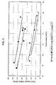
- FIG. 1 illustrates hydrocarbon conversion (wt%) and cut gasoline sulfur reduction performance of the invention (Catalyst 1C of Example 1) versus a base equilibrium catalyst (E-cat 1D) and other catalysts (Catalyst 1A & 1B) using deactivation Protocol 1 described later below (CPS 1450°F (788°C) ending on reduction).
- FIG. 2 illustrates hydrocarbon conversion (wt%) and cut gasoline sulfur reduction performance of the invention (Catalyst 1C of Example 1) versus a base equilibrium catalyst (E-cat 1D) and other catalysts (Catalyst 1A & 1B) using deactivation Protocol 2 described later below (CPS 1450°F (788°C) ending on oxidation).
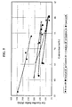
- FIG. 3 illustrates hydrocarbon conversion (wt%) and cut gasoline sulfur reduction performance of the invention (Catalyst 1C of Example 1) versus a base equilibrium catalyst (E-cat 1D) and other catalysts (Catalyst 1A & 1B) using deactivation Protocol 3 described later below (4 hours at 1500°F (816°C) 100% Steam).
- FIG. 4 illustrates hydrocarbon conversion (wt%) and cut gasoline sulfur reduction performance of the invention (Catalyst 1C of Example 1) versus a base equilibrium catalyst (E-cat 1D) and other catalyst (Catalyst 1A) using deactivation Protocol 1 described later below (CPS 1450°F (788°C) ending on reduction without SO 2 ).
- FIG. 5 illustrates the effect of zinc concentration and yttrium concentration on the invention with respect to its cut gasoline sulfur reduction as further described in Example 2.
- FIG. 6 illustrates the effect of zinc concentration and yttrium concentration on the invention with respect to its LCO sulfur reduction as further described in Example 2.
- FIG. 7 illustrates the effect of the invention versus catalysts that do not contain both, e.g., zinc, and yttrium on cut gasoline sulfur reduction as further described in Example 3.
- FIG. 8 illustrates the effect of the invention versus catalysts that do not contain both, e.g., zinc, and yttrium on LCO sulfur reduction as further described in Example 3.
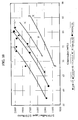
- FIG. 9 illustrates the hydrocarbon conversion (wt%) and cut gasoline sulfur reduction performance of the invention (Catalyst 4C and 4D of Example 4) versus a base equilibrium catalyst (E-cat 1D) and other catalysts (Catalyst 4A & 4B).
- FIG. 10 illustrates the hydrocarbon conversion (wt%) and LCO sulfur reduction performance of the invention (Catalyst 4C and 4D of Example 4) versus a base equilibrium catalyst (E-cat 1D) and other catalysts (Catalyst 4A & 4B).
- the present invention is an improved cracking catalyst composition
- zeolite yttrium, and at least one element selected from the group consisting of zinc, magnesium, and manganese, wherein the yttrium and the element are present as cations.
- the catalyst composition preferably comprises zinc as the aforementioned element in amounts of about 0.1 % to about 14%.
- the catalyst also preferably comprises about 0.1% to about 12% by weight yttrium.
- the element and yttrium are generally present in the composition as cations that have been exchanged onto the zeolite.
- the zeolite is preferably zeolite Y.
- the invention can further contain rare earth, e.g., when rare earth exchanged Y zeolite is employed.
- composition is particularly suited for use in a fluidized catalytic cracking process (FCC).
- FCC fluidized catalytic cracking process
- preferred embodiments of the invention comprise fluidizable particles having an average particle size in the range of about 20 to about 100 microns, and further comprise matrix and optionally binder, e.g., clay and alumina.
- the invention also provides for a new method of reducing the sulfur content of a catalytically cracked petroleum fraction, which comprises catalytically cracking a petroleum feed fraction containing organosulfur compounds at elevated temperature in the presence of a cracking catalyst comprising zeolite, yttrium, and at least one element selected from the group consisting of zinc, magnesium, and manganese, wherein the yttrium and element are present as cations.
- a cracking catalyst comprising zeolite, yttrium, and at least one element selected from the group consisting of zinc, magnesium, and manganese, wherein the yttrium and element are present as cations.
- the invention further comprises a new fluid catalytic cracking process in which a hydrocarbon feed comprising organosulfur compounds is catalytically cracked to lighter products by contact in a cyclic catalyst recirculation cracking process with a circulating fluidizable catalytic cracking catalyst inventory consisting of particles having a size ranging from about 20 to about 100 microns, comprising: (i) catalytically cracking the feed in a catalytic cracking zone operating at catalytic cracking conditions by contacting feed with a source of regenerated cracking catalyst to produce a cracking zone effluent comprising cracked products and spent catalyst containing coke and strippable hydrocarbons; (ii) discharging and separating the effluent mixture into a cracked product rich vapor phase and a solids rich phase comprising spent catalyst; (iii) removing the vapor phase as a product and fractionating the vapor to form liquid cracking products including gasoline, (iv) stripping the solids rich spent catalyst phase to remove occluded hydrocarbon
- FCC catalysts typically contain zeolite, which is a fine porous powdery material composed of the oxides of silicon and aluminum.
- the zeolites are typically incorporated into matrix and/or binder and particulated, or, a clay based particulate can be "zeolitized” after microspheres are formed. See “ Commercial Preparation and Characterization of FCC Catalysts", Fluid Catalytic Cracking: Science and Technology, Studies in Surface Science and Catalysis, Vol. 76, p. 120 (1993 ).
- the particulated catalytic material attains a fluid-like state that allows the material to behave like a liquid.
- This property permits the catalyst to have enhanced contact with the hydrocarbon feedstock feed to the FCC unit and to be circulated between the FCC reactor and the other units of the overall FCC process (e.g., regenerator).
- the term "fluid" has been adopted by the industry to describe this material.
- FCC catalysts typically have average particle sizes in the range of about 20 to about 100 microns. While the compositions of this invention have shown to be particularly suitable for use in FCC, it is envisioned that the composition can be used in other catalytic hydrocarbon conversion processes where it is desirable to produce low sulfur products.
- the zeolite suitable for preparing this invention can be any zeolite having catalytic activity in a hydrocarbon conversion process.
- the zeolite should be one capable of being exchanged with yttrium and other cations required to make the invention.
- the zeolites can be large pore size zeolites that are characterized by a pore structure with an opening of at least 0.7 nm and medium or intermediate pore size zeolites having a pore size smaller than 0.7 nm but larger than about 0.56 nm. Suitable large pore zeolites are described further below.
- Suitable medium pore size zeolites include pentasil zeolites such as ZSM-5, ZSM-22, ZSM-23, ZSM-35, ZSM-50, ZSM-57, MCM-22, MCM-49, MCM-56 all of which are known materials.
- Other zeolites that may be used also include those zeolites with framework metal elements other than aluminum, for example, boron, gallium, iron, chromium.
- Suitable large pore zeolites comprise crystalline alumino-silicate zeolites such as synthetic faujasite, i.e., type Y zeolite, type X zeolite, and Zeolite Beta, as well as heat treated (calcined) and/or rare-earth exchanged derivatives thereof.
- Zeolites that are particularly suited include calcined, rare-earth exchanged type Y zeolite (CREY), the preparation of which is disclosed in U.S. Pat. No. 3,402,996 , ultra stable type Y zeolite (USY) as disclosed in U.S. Pat. No. 3,293,192 , as well as various partially exchanged type Y zeolites as disclosed in U.S. Pat.
- Suitable large pore zeolites include MgUSY, ZnUSY, MnUSY, HY, REY, CREUSY, REUSY zeolites, and mixtures thereof.
- a yttrium exchanged Y zeolite is particularly preferred.
- the zeolite of this invention may also be blended with molecular sieves such as SAPO and ALPO as disclosed in U.S. Pat. No. 4,764,269 .
- Standard Y-type zeolite is commercially produced by crystallization of sodium silicate and sodium aluminate. This zeolite can be converted to USY-type by dealumination, which increases the silicon/aluminum atomic ratio of the parent standard Y zeolite structure. Dealumination can be achieved by steam calcination or by chemical treatment. In embodiments where clay microspheres are "zeolitized" in situ to form zeolite Y, the zeolite Y is formed from calcined clay microspheres by contacting the microspheres to caustic solution at 180°F (82°C). See Studies in Surface Science and Catalysis, supra.
- the rare earth exchanged zeolites used in the invention are prepared by ion exchange, during which sodium atoms present in the zeolite structure are replaced with other cations, usually as mixtures of rare-earth metal salts such as those salts of cerium, lanthanum, neodyminum, naturally occurring rare-earths and mixtures thereof to provide REY and REUSY grades, respectively. These zeolites may be further treated by calcinations to provide the aforementioned CREY and CREUSY types of material.
- MgUSY, ZnUSY and MnUSY zeolites can be formed by using the metal salts of Mg, Zn or Mn or mixtures thereof in the same manner as described above with respect to the formation of REUSY except that salts of magnesium, zinc or manganese is used in lieu of the rare-earth metal salt used to form REUSY.
- the unit cell size of a preferred fresh Y-zeolite is about 24.45 to 24.7 ⁇ .
- the unit cell size (UCS) of zeolite can be measured by X-ray analysis under the procedure of ASTM D3942. There is normally a direct relationship between the relative amounts of silicon and aluminum atoms in the zeolite and the size of its unit cell. This relationship is fully described in Zeolite Molecular Sieves, Structural Chemistry and Use (1974) by D. W. Breck at Page 94 , which teaching is incorporated herein in its entirety by reference.
- the unit cell size value of a zeolite also decreases as it is subjected to the environment of the FCC regenerator and reaches equilibrium due to removal of the aluminum atoms from the crystal structure.
- its framework Si/Al atomic ratio increases from about 3:1 to about 30:1.
- the unit cell size correspondingly decreases due to shrinkage caused by the removal of aluminum atoms from the cell structure.
- the unit cell size of a preferred equilibrium Y zeolite is at least 24.22 ⁇ , preferably from 24.28 to 24.50 ⁇ , and more preferably from 24.28 to 24.38 ⁇ .
- Yttrium can be present in the composition in amounts ranging from about 0.1% to about 12% by weight of the composition.
- the element selected from the group consisting of zinc, magnesium and manganese can be present in the composition in amounts ranging from about 0.1% to about 14% by weight composition.
- the specific amount of yttrium and the aforementioned element for a particular embodiment depends on a number of factors, including, but not limited to, the amount of zeolite present, the ion exchange capacity of the selected zeolite and, with respect to the aforementioned element, which element is selected, For example, if zinc is selected as the aforementioned element, the amount of zinc is generally in the range of 0.1 to about 14% by weight, whereas the amount of magnesium is generally in the range of about 0.1 to about 5% and the amount of manganese is about 0.1 to about 12%.
- the catalyst typically comprises about 0.5% to about 5% by weight yttrium and about 1.5% to about 5% by weight zinc.
- the amount of the aforementioned element and yttrium can alternatively be measured as an oxide in amounts measured in grams per square meter of catalyst surface area.
- the aforementioned element and yttrium can each be present in amounts of at least about 1x10 -5 gr/m 2 of total catalyst surface area. More typically, zinc can be found in amounts of at least about 1.6x10 -4 gr/m 2 , magnesium in amounts of at least about 5x10 -5 gr/m 2 , manganese in amounts of at least about 1.3x10 -4 gr/m 2 , and yttrium in amounts of at least about 7x10 -4 gr/m 2 .
- the weight and surface area are measured, respectively, by ICP and BET surface area methodologies.
- the yttrium and the aforementioned element(s) are present as cations exchanged onto the zeolite, but depending on the method used, a portion of the yttrium and the element could be found in pores of the catalyst matrix. In those instances the yttrium and/or elements are usually part of a solid solution with the matrix, and up to about 25% of the yttrium and/or element present in the composition could be in this form.
- the catalyst can also comprise additional components, including, but not limited to, matrix and/or binders.
- Suitable matrix materials include, but are not limited to, active matrices such as alumina, silica, porous alumina-silica, and kaolin clay.
- Alumina is preferred for some embodiments of the invention, and may form all or part of an active-matrix component of the catalyst.
- active it is meant the material has activity in converting and/or cracking hydrocarbons in a typical FCC process.
- Suitable binders include those materials capable of binding the matrix and zeolite into particles.
- Specific suitable binders include, but are not limited to, alumina sols, silica sols, aluminas, and silica aluminas.
- Methods for preparing the invention include, but are not necessarily limited to, the following general processes.
- spray drying is one process that can be used in any of the above-described methods to form the catalyst.
- the resulting slurry can be spray dried into particles having an average particle size in the range of about 20 to about 100 microns, and the resulting catalyst particulate is then processed under conventional conditions.
- the source of yttrium in any of the above methods is generally in the form of a yttrium salt, and includes, but is not limited to yttrium halides such as chlorides, fluorides, bromides, and iodides. Yttrium carbonate, sulfate, nitrates and acetates are also suitable sources.
- the source of the yttrium is usually aqueous based and yttrium can be present at concentrations of about 1 to about 30%. It is usually preferable to conduct the exchange such that at least 15% and up to about 75% of exchange sites present on the zeolite are exchanged with yttrium cations.
- the source of the element selected from the group consisting of zinc, magnesium and manganese is also generally a salt, with halides, carbonates, sulfates, nitrates, acetate, and the like being suitable.
- the sources of these elements are also generally aqueous based and the element can be present at concentrations of about 1% to about 40%.
- the source of the rare earth is also generally a salt, with the counter anion being one of those mentioned above with respect to yttrium and the aforementioned element.
- Rare earth can be incorporated into the composition by any of the above-mentioned methods for incorporating yttrium and/or the element.
- the rare earth is introduced as pre-exchanged cation on the zeolite before matrix and other components in the invention are combined with the zeolite.
- the starting zeolite can be a zeolite such as REY, REUSY, and CREY.
- a suitable clay matrix comprises kaolin.
- Suitable materials for binders include inorganic oxides, such as alumina, silica, silica alumina, aluminum phosphate, as well as other metal-based phosphates known in the art.
- Suitable dispersible sols include alumina sols and silica sols known in the art. Suitable alumina sols are those prepared by peptizing alumina using strong acid and particularly suitable silica sols include Ludox® colloidal silica available from W.R. Grace & Co.-Conn.
- binders e.g., those formed from binder precursors, e.g., aluminum chlorohydrol, are created by introducing solutions of the binder's precursors into the mixer, and the binder is then formed upon being spray dried and/or further processed, e.g., calcination.
- binder precursors e.g., aluminum chlorohydrol
- one method of making the invention comprises spray drying a slurry of zeolite Y, rare earth, clay and alumina sol, and then washing and calcining the resulting particulates.
- the calcined particles are then subjected to a "post impregnation" solution comprising the yttrium and aforementioned element.
- the catalyst is made by sequentially impregnating each of the components onto the spray dried particle, e.g., first impregnating the catalyst particles with yttrium, then subsequently subjecting the yttrium impregnated catalyst with a bath containing at least one element selected from the group consisting of zinc, magnesium and manganese.
- the post impregnation solution concentrations depends on the incipient wetness process used, but in general, the concentration of yttrium and the aforementioned element is generally higher than that of the solutions used to directly exchange the zeolites.
- the yttrium and element is post exchanged onto zeolite as per (3) mentioned above using conventional ion-exchange conditions. Indeed when preparing zeolite Y in situ, this aforementioned method is employed except zeolite Y is not included and clay is not optional.
- the clay microspheres are then treated in caustic at elevated temperatures to form the zeolite prior to impregnation and/or ion exchange.
- the present catalyst is used as a catalytic component of the circulating inventory of catalyst in a catalytic cracking process, which is typically the fluid catalytic cracking (FCC) process.
- FCC fluid catalytic cracking
- the invention will be described with reference to the FCC process although the present catalyst could be used in a moving bed type (TCC) cracking process with appropriate adjustments in particle size to suit the requirements of the process.
- TCC moving bed type
- the invention is suited for a fluid catalytic cracking process in which a heavy hydrocarbon feed containing the organosulfur compounds will be cracked to lighter products by contact of the feed in a cyclic catalyst recirculation cracking process with a circulating fluidizable catalytic cracking catalyst inventory consisting of particles having a size ranging from about 20 to about 100 microns.
- the significant steps in the cyclic process are: (i) the feed is catalytically cracked in a catalytic cracking zone, normally a riser cracking zone, operating at catalytic cracking conditions by contacting feed with a source of hot, regenerated cracking catalyst to produce an effluent comprising cracked products and spent catalyst containing coke and strippable hydrocarbons; (ii) the effluent is discharged and separated, normally in one or more cyclones, into a vapor phase rich in cracked product and a solids rich phase comprising the spent catalyst; (iii) the vapor phase is removed as product and fractionated in the FCC main column and its associated side columns to form liquid cracking products including gasoline, (iv) the spent catalyst is stripped, usually with steam, to remove occluded hydrocarbons from the catalyst, after which the stripped catalyst is oxidatively regenerated to produce hot, regenerated catalyst which is then recycled to the cracking zone for cracking further quantities of feed.
- the sulfur content of the gasoline portion of the liquid cracking products is effectively brought to lower and more acceptable levels by carrying out the catalytic cracking in the presence of the invention being used as a product sulfur reduction catalyst.
- the catalyst of this invention has been shown to not only reduce gasoline range sulfur, but also reduce LCO sulfur.
- LCO sulfur is not a particularly significant issue when the distillation process after a FCC unit results in relatively clean cuts. It is, however, not unusual that such distillations do not result in as clean a cut, that is, the gasoline fraction will frequently also contain LCO fraction. Therefore, employing a sulfur reduction catalyst in the FCC unit capable of reducing LCO sulfur is advantageous when one desires to reduce sulfur present in a range of species, particularly LCO sulfur carried over into the gasoline fraction from the distillation tower.
- the form of zinc and yttrium for incorporation into the catalyst does not exhibit dehydrogenation activity to a marked degree.
- catalytically active components may be present in the circulating inventory of catalytic material in addition to the cracking catalyst of this invention and/or may be included with the invention when the invention is being added to a FCC unit.
- examples of such other materials include the octane enhancing catalysts based on zeolite ZSM-5, CO combustion promoters based on a supported noble metal such as platinum, stack gas desulfurization additives such as DESOX® (magnesium aluminum spinel), vanadium traps, bottom cracking additives, such as those described in Krishna, Sadeghbeigi, op cit and Scherzer, "Octane Enhancing Zeolitic FCC Catalysts", Marcel Dekker, N.Y., 1990, ISBN 0-8247-8399-9, pp. 165-178 and other gasoline sulfur reduction products such as those described in U.S. Patent 6,635,169 . These other components may be used in their conventional amounts.
- the effect of the present catalyst is to reduce the sulfur content of the liquid cracking products, especially the light and heavy gasoline fractions although reductions are also noted in the light cycle oil, making this more suitable for use as a diesel or home heating oil blend component.
- the sulfur removed by the use of the catalyst is converted to inorganic form and released as hydrogen sulfide which can be recovered in the normal way in the product recovery section of the FCCU in the same way as the hydrogen sulfide conventionally released in the cracking process.
- the increased load of hydrogen sulfide may impose additional sour gas/water treatment requirements but with the significant reductions in gasoline sulfur achieved, these are not likely to be considered limitative.
- gasoline sulfur can be achieved by the use of the present catalysts, in some cases up to about 70% based on microactivity testing relative to the base case using a conventional cracking catalyst, at constant conversion, using the preferred form of the catalyst described above.
- Gasoline sulfur reduction of 30% is readily achievable with many of the additives according to the invention, as shown by the Examples below.
- the extent of sulfur reduction may depend on the original organic sulfur content of the cracking feed and the FCC process conditions.
- Sulfur reduction may be effective not only to improve product quality but also to increase product yield in cases where the refinery cracked gasoline end point has been limited by the sulfur content of the heavy gasoline fraction; by providing an effective and economical way to reduce the sulfur content of the heavy gasoline fraction, the gasoline end point may be extended without the need to resort to expensive hydrotreating, with a consequent favorable effect on refinery economics. Removal of the various thiophene derivatives which are refractory to removal by hydrotreating under less severe conditions is also desirable if subsequent hydrotreatment is contemplated.
- catalytic gasoline sulfur reduction in the FCCU can allow the refiner to process a higher sulfur feedstock. These sour feedstocks are typically less expensive and thus have a favorable economic benefit to the refiner.
- Gasoline sulfur reduction in the FCCU can also positively impact the operation of downstream naphtha hydrotreaters. By achieving a large portion of the required sulfur reduction inside the FCCU, the naphtha hydrotreater can be operated less severely, thereby minimizing octane loss from olefin saturation and minimizing hydrogen consumption. Octane loss from olefin saturation and minimizing hydrogen consumption. This would also have a favorable economic impact to the refiner.
- “Fresh” fluid cracking catalyst is catalyst composition, as manufactured but prior to being added to a FCC unit.
- “Equilibrium” fluid cracking catalyst, "spent catalyst”, or “regenerated catalyst” is the inventory of circulating catalyst composition in an FCC unit once it has reached a steady state within the environment of the FCCU.
- Standard Equilibrium refers to fluid cracking catalyst that has been steam treated in the laboratory to simulate an equilibrium cracking catalyst of an FCCU.
- One such laboratory procedure for attaining simulated equilibrium is to steam fresh catalyst, such as 1500°F (816°C) for 4 hours or 1420°F (771 °C) for 16 hours with one atmosphere of steam.
- steam fresh catalyst such as 1500°F (816°C) for 4 hours or 1420°F (771 °C) for 16 hours with one atmosphere of steam.
- Such treatment simulates catalyst deactivation that is believed to be substantially the same as that of an equilibrium catalyst in a FCC unit once it has reached a steady state within the environs of a FCCU.
- CPS is another deactivation procedure which uses propylene and air to simulate the REDOX process in addition to the steaming deactivation effect (See American Chemical Society Symposium Series, No. 634, Page 171-183 (1996 ).
- Standard Y-type zeolite was commercially produced by crystallization of sodium silicate and sodium aluminate. This zeolite can be converted to USY-type by dealumination , which increases the silicon/aluminum atomic ratio of the parent standard Y zeolite structure. Dealumination is achieved by steam calcinations.
- the rare earth (RE) exchanged zeolites used in the invention are prepared by ion exchange, during which sodium and ammonium atoms present in the zeolite structure are replaced with other cations, usually as mixtures of rare-earth metal salts such as those salts of cerium, lanthanum, neodyminum, naturally occurring rare-earths and mixtures thereof to provide REY and REUSY grades, respectively.
- the surface area was measured by N 2 BET method and chemical analysis was performed by ion coupled plasma analysis, standardized to NIST standards.
- RE refers to rare earth.
- SA refers to total surface area in m 2 / g.
- ZSA refers to surface area in m 2 / g from the zeolite or microporosity less than 20 Angstroms.
- MSA refers to surface area in m 2 / g from the matrix or mesoporosity greater than 20 Angstroms.
- APS refers to average particles size in microns.
- UCS refers to unit cell size in Angstroms.
- PPM refers to parts per million.
- GSR gasoline sulfur reduction.
- LCO refers to light cycle oil, typically have a boiling point in the range of about 220°C to about 372°C.
- Catalyst 1A 4203 grams (1350g on a dry basis) of RE-USY with 8.2% RE 2 O 3 , 0.15% Na 2 O was mixed with 547g of a ZnCl 2 , solution containing 29.6% Zinc for 10 minutes. Then, 1761g (405g on a dry basis) aluminum chlorohydrol and 2991g (2542g on a dry basis) clay were added in the above slurry and mixed for about 10 minutes. The mixture was milled in a Drais mill to reduce particle size and spray dried in a Bowen spray dryer. The spray dried particles were calcined for 1 hour at 1100°F (593°C). The physical and chemical properties of the finished fresh catalyst are listed on Table 1.
- Catalyst 1B 3663 grams (1200g on a dry basis) of RE-USY with 8.2% RE 2 O 3 , 0.15% Na 2 O was mixed with 486g of a ZnCl 2 solution containing 29.6% Zinc and 667g of a RECl 3 solution containing 19.6% rare earth for 10 minutes. Then, 1565g (360g on a dry basis) aluminum chlorohydrol and 2447g (2080g on a dry basis) clay were added in the above slurry and mixed for about 10 minutes. The mixture was milled in a Drais mill to reduce particle size and spray dried in a Bowen spray dryer. The spray dried particles were calcined for 1 hour at 1100°F (593°C). The physical and chemical properties of the finished fresh catalyst are also listed on Table 1.
- Catalyst 1C (Invention). 3663 grams (1319g on a dry basis) of RE-USY with 8.2% RE 2 O 3 , 0.15% Na 2 O was mixed with 486g of a ZnCl 2 solution containing 29.6% Zinc and 600g of a YCl 3 solution containing 15.7% yttrium for 10 minutes. Then, 1565g (360g on a dry basis) aluminum chlorohydrol and 2447g (2080g on a dry basis) clay were added in the above slurry and mixed for about 10 minutes. The mixture was milled in a Drais mill to reduce particle size and spray dried in a Bowen spray dryer. The spray dried particles were calcined for 1 hour at 1100°F (593°C). The physical and chemical properties of the finished fresh catalyst are listed on Table 1.
- Micro-Activity Tests were conducted thereon according to ASTM D3907 against an equilibrium zeolite-containing catalysts (E-cat 1D), having a unit cell size of 24.30 ⁇ , total surface area of 174 m 2 /g, zeolite surface area of 134 m 2 /g, and matrix surface area of 40 m 2 /g.
- the E-cat 1D composition has a Na 2 O of 0.27%, RE 2 O 3 of 2.58%, Y 2 O 3 of 0.005%, and ZnO of 0.02%.
- the properties of the feed used in the MAT study are listed in column 2 of Table 2 below. Column 1 of Table 2 provides a range of values for certain properties found in typical FCC feeds.
- sulfur species ranging from thiophene to C2-thiophene was defined as “light cut gasoline sulfur” and sulfur species ranging from C3-thiophene to C4-thiophene as “heavy cut gasoline sulfur”.
- benzothiophene is included in the sulfur report, it is referred to as “total gasoline sulfur”.
- a starting base catalyst was made by mixing 3767 grams (1500g on a dry basis) of the yttrium exchanged zeolite above with 400g deionized water, 2391g (550g on a dry basis) aluminum chlorohydrol and 3471g (2950g on a dry basis) clay for about 10 minutes. The mixture was milled in a Drais mill to reduce particle size and spray dried in a Bowen spray dryer. The finished catalysts were calcined and exchanged using ammonium sulfate to lower the Na 2 O content. The physical and chemical properties of the starting base catalyst are listed on Table 7.
- Catalyst 2A 100g of the starting base catalyst were impregnated to a Zn level of 1.84% followed by a calcination of 1 hour at 1100°F (593°C).
- Catalyst 2B 100g of the starting base catalyst were impregnated to a Zn level of 2.90% followed by a calcination of 1 hour at 1100°F (593°C).
- Catalyst 2C 100g of the starting base catalyst were impregnated to a Zn level of 2.73% and additional 0.91% yttrium followed by a calcination of 1 hour at 1100°F (593°C).
- Catalyst 2D 100g of the starting base catalyst were impregnated to a Zn level of 2.77% and additional 1.88% yttrium followed by a calcination of 1 hour at 1100°F (593°C).
- Catalyst 2E 100g of the starting base catalyst were impregnated to a Zn level of 2.46% and additional 3.9% yttrium followed by a calcination of 1 hour at 1100°F (593°C).
- Catalyst 2A is less active in sulfur reduction than that of Catalyst 2B (33% vs. 41% cut gasoline sulfur reduction).
- Catalyst 2B vs. 2C improves cut gasoline sulfur reduction from ⁇ 41% to 54%.
- a further increase of yttrium from ⁇ 2.1% to 3.07% did not enhance cut gasoline sulfur reduction, and a further yttrium loading to 5.12% appears to decrease gasoline sulfur reduction activity.
- Example 2 The same starting base catalyst in the Example 2 was impregnated with 1.23% yttrium using YCl 3 solution to incipient wetness followed by calcinations of 1 hour at 1100°F (593°C).
- the finished catalyst is named Catalyst 3A.
- Three additional catalysts were made by incipient wetness impregnation of Catalyst 3A using ZnCl 2 solution.
- Catalyst 3B 110g of catalyst 3A were impregnated to a Zn level of 2.39% followed by a calcination of 1 hour at 1100°F (593°C).
- Catalyst 3C 110g of catalyst 3A were impregnated to a Zn level of 3.16% followed by a calcination of 1 hour at 1100°F (593°C).
- Catalyst 3D 110g of catalyst 3A were impregnated to a Zn level of 3.97% followed by a calcination of 1 hour at 1100°F (593°C).
- Catalyst 4A 7520 grams (2400g on a dry basis) of RE-USY with 8.2% RE 2 O 3 , ⁇ 1% Na 2 O was mixed with 973g of a ZnCl 2 solution containing 29.6% Zinc for 10 minutes. Then, 3130g (720g on a dry basis) aluminum chlorohydrol and 5318g (4520g on a dry basis) clay were added in the above slurry and mixed for about 10 minutes. The mixture was milled in a Drais mill to reduce particle size and spray dried in a Bowen spray dryer. The spray dried particles were calcined for 40 minutes at 750°F (399°C) and followed by an ammonium sulfate exchange to lower Na 2 O. The physical and chemical properties of the finished catalyst are listed on Table 11.
- Catalyst 4B 5641 grams (1800g on a dry basis) of the same RE-USY with 8.2% RE 2 O 3 , ⁇ 1% Na 2 O was mixed with 730g of a ZnCl 2 solution containing 29.6% Zinc and 389g RECl 3 solution containing 23% rare earth for 10 minutes. Then, 2348g (540g on a dry basis) aluminum chlorohydrol and 3865g (3285g on a dry basis) clay were added in the above slurry and mixed for about 10 minutes. The mixture was milled in a Drais mill to reduce particle size and spray dried in a Bowen spray dryer. The spray dried particles were calcined for 40 minutes at 750°F (399°C) and followed by an ammonium sulfate exchange to lower Na 2 O The physical and chemical properties of the finished catalyst are listed on Table 11.
- Catalyst 4C (Invention) 4700 grams (1500g on a dry basis) of the same RE-USY with 8.2% RE 2 O 3 , ⁇ 1% Na 2 O was mixed with 608g of a ZnCl 2 solution containing 29.6% Zinc and 729g YCl 3 solution containing 9.44% yttrium for 10 minutes. Then, 1957g (450g on a dry basis) aluminum chlorohydrol and 3221g (2738g on a dry basis) clay were added in the above slurry and mixed for about 10 minutes. The mixture was milled in a Drais mill to reduce particle size and spray dried in a Bowen spray dryer. The spray dried particles were calcined for 40 minutes at 750°F (399°C) and followed by an ammonium sulfate exchange to lower Na 2 O. The physical and chemical properties of the finished catalyst are listed on Table 11.
- Catalyst 4D. (Invention). 1806 grams (1560g on a dry basis) of the Yttrium-USY described in Example 3 was mixed with 2660g of deionized H 2 O and 632g ZnCl 2 solution containing 29.6% Zinc and 758g YCl 3 solution containing 9.44% yttrium for 10 minutes. Then, 2035g (468g on a dry basis) aluminum chlorohydrol and 3349g (2847g on a dry basis) clay were added in the above slurry and mixed for about 10 minutes. The mixture was milled in a Drais mill to reduce particle size and spray dried in a Bowen spray dryer. The spray dried particles were calcined for 40 minutes at 750°F (399°C) and followed by an ammonium sulfate exchange to lower Na 2 O. The physical and chemical properties of the finished catalyst are listed on Table 11.
Abstract
Description
- The present invention is directed to an improved catalyst composition useful in fluid catalytic cracking processes. The present catalyst composition is capable of reducing sulfur compounds normally found as part of the gasoline fraction streams of such processes. The present invention accordingly provides product streams of light and heavy gasoline fractions with substantially lower amounts of sulfur-containing compounds, and an improved catalytic cracking process when the invention is used as a catalyst in such processes.
- Catalytic cracking is a petroleum refining process that is applied commercially on a very large scale. Indeed, fluidized catalytic cracking (FCC) processes produce a large amount of the refinery gasoline blending pool in the United States. In the process, heavy hydrocarbon feedstocks are converted into lighter products by reactions taking place at elevated temperatures in the presence of a catalyst, with the majority of reactions taking place in the vapor phase. The feedstock is thereby converted into gasoline, distillates and other liquid fraction product streams as well as lighter gaseous cracking products having four or less carbon atoms per molecule. The three characteristic steps of a catalytic cracking process comprises: a cracking step in which the heavy hydrocarbon feed stream is converted into lighter products, a stripping step to remove adsorbed hydrocarbons from the catalyst material, and a regeneration step to burn off coke formations from the catalyst material. The regenerated catalyst is then recirculated and reused in the cracking step.
- Catalytically cracked feedstocks normally contain organic sulfur compounds, such as mercaptans, sulfides, thiophenes, benzothiophenes, dibenzothiophenes, and other sulfur-containing species. The products of the cracking process correspondingly tend to contain sulfur impurities even though about half of the sulfur compounds are converted to hydrogen sulfide during the cracking process, mainly by catalytic decomposition of non-thiophenic sulfur compounds. See, Wormsbecher et al., National Petroleum Refiners Meeting, New Orleans, paper AM-92-15 (1992). The thiophenic compounds have been found to be most difficult to remove. The specific distribution of sulfur in the cracking products is dependent on a number of factors including feed, catalyst type, additives present, conversion and other operating conditions, but, in any event a certain proportion of the sulfur tends to enter the light or heavy gasoline fractions and passes over into the product pool, including sulfur from light cycle oil fractions, discussed later below.
- Although petroleum feedstock normally contains a variety of sulfur bearing contaminants, one of the chief concerns is the presence of unsubstituted and hydrocarbyl substituted thiophenes and their derivatives, such as thiophene, methylthiophene, ethylthiophene, propylthiophene, tetrahydrothiophene, benzothiophene and the like in the heavy and light gasoline fraction product streams of FCC processes. The thiophenic compounds generally have boiling points within the range of the light and heavy gasoline fractions and, thus, become concentrated in these product streams. With increasing environmental regulation being applied to petroleum products, for example in the Reformulated Gasoline (RFG) regulations, there has been numerous attempts to reduce the sulfur content of the products, especially those attributable to thiophenic compounds.
- One approach has been to remove the sulfur from the FCC feed by hydrotreating before cracking is initiated. While highly effective, this approach tends to be expensive in terms of the capital cost of the equipment as well as operationally since hydrogen consumption is high. Another approach has been to remove the sulfur from the cracked products by hydrotreating. Again, while effective, this solution has the drawback that valuable product octane may be lost when the high octane olefinic components become saturated.
- From an economic point of view, it would be desirable to achieve thiophenic sulfur removal in the cracking process itself since this would effectively desulfurize the major components of the gasoline blending pool without additional treatment. Various catalytic materials have been developed for the removal of sulfur during the FCC process cycle. For example, an FCC catalyst impregnated with vanadium has been shown to reduce the level of product sulfur (See
U.S. Patent 6,482,315 ). This reference also discloses a sulfur reduction additive based on a zinc-impregnated alumina. - Other developments for reducing product sulfur have centered on the removal of sulfur from the regenerator stack gases. An early approach developed by Chevron used alumina compounds as additives to the inventory of cracking catalyst to adsorb sulfur oxides in the FCC regenerator; the adsorbed sulfur compounds which entered the process in the feed were released as hydrogen sulfide during the cracking portion of the cycle and passed to the product recovery section of the unit where they were removed (See Krishna et al., Additives Improved FCC Process, Hydrocarbon Processing, November 1991, pages 59-66). Although sulfur is removed from the stack gases of the regenerator, liquid product sulfur levels are not greatly affected, if at all.
- An alternative technology for the removal of sulfur oxides from regenerator stack gases is based on the use of magnesium-aluminum spinels as additives to the circulating catalyst inventory in the FCC unit (FCCU). Exemplary patents disclosing this type of sulfur removal additives include
U.S. Patent Nos. 4,963,520 ;4,957,892 ;4,957,718 ;4,790,982 and others. Again, however, sulfur content in liquid products, such as gasoline, was not greatly affected. - A catalyst composition to reduce sulfur levels in liquid cracking products has been described by
Wormsbecher and Kim in U.S. Patents 5,376,608 and5,525,210 . These patents propose the addition of low amounts of an additive composed of an alumina-supported Lewis Acid to conventional zeolite-containing cracking catalyst. Although this system has the advantages of causing sulfur reduction in the cracking process, it is generally believed that use of greater than about 10 weight percent of the described additives in the catalyst composition does not provide a benefit (e.g. high sulfur removal while retaining the selectivity of other products) proportional to the level of the additive. In view of the fact that an FCCU can only contain a fixed amount of fluidized particulates, the inclusion of additives, such as the alumina-supported Lewis Acid additives of Wormsbecher and Kim, causes a reduction in the amount of the base cracking catalyst contained in the FCCU and thus, a proportional reduction in the conversion of heavy feedstock to desired products. -
U.S. 6,635,168 discloses a FCC catalyst composition composed of Lewis Acid-containing alumina and Y-type zeolite containing catalyst to provide a composition having a kinetic conversion activity of at least 2. This product was developed in part to address disadvantages associated with the aforementioned Lewis Acid components. Indeed, the compositions described inU.S. 6,635,168 provide a reduced sulfur (e.g., thiophenes and derivatives thereof) content in light and heavy gasoline fractions of the FCC processes, (about 34%). - Pending
U.S. Patent application 10/801,424 filed on March 16, 2004 - The aforementioned gasoline sulfur product pertains to Lewis Acid supported on non-zeolitic supports. It has also been described, however, that Lewis Acid based gasoline sulfur reduction products can be prepared by associating Lewis Acid with zeolite, and in particular rare earth exchanged zeolites. It has now been discovered that, depending on the loading of Lewis Acid, e.g., zinc-based compounds, and any rare earth present, the gasoline sulfur reduction (GSR) activity of these catalysts can be dramatically decreased after hydrothermal deactivation due to diminishing amount of available zeolite exchange sites after severe dealumination or a dramatic reduction of zeolite surface area. Even in the cases where the amounts of Lewis Acid and any rare earth are carefully optimized to maximize the hydrothermal stability of such catalysts, the sulfur reduction activity of a catalyst, e.g., Zn exchanged RE-USY catalysts, can be substantially reduced after hydrothermal deactivation, which has a redox cycle built in. A FCC catalyst constantly goes through alternative reduction and oxidation cycles under hydrothermal conditions in a FCC process and therefore avoiding these cycles is not usually possible. These shortcomings have limited the use of these types of catalysts.
- It also has been found that the aforementioned low soda embodiments are only reducing specific species of sulfur compounds, and it would be desirable to find a catalyst capable of reducing a wider variety of sulfur containing species, e.g., LCO sulfur.
- Sulfur standards are becoming more stringent as evidenced by the fact that the U.S. Environmental Protection Agency has set new standards for gasoline sulfur content and is reducing the average from the current standard of 350 ppm sulfur to about 30 ppm by 2006. It therefore would be desirable to have a catalyst composition suitable for use in FCC processes wherein the catalyst is capable of significantly reducing the level sulfur even further than those achieved using additives described in
WO 02/08300 -
FIG. 1 illustrates hydrocarbon conversion (wt%) and cut gasoline sulfur reduction performance of the invention (Catalyst 1C of Example 1) versus a base equilibrium catalyst (E-cat 1D) and other catalysts (Catalyst 1A & 1B) using deactivation Protocol 1 described later below (CPS 1450°F (788°C) ending on reduction). -
FIG. 2 illustrates hydrocarbon conversion (wt%) and cut gasoline sulfur reduction performance of the invention (Catalyst 1C of Example 1) versus a base equilibrium catalyst (E-cat 1D) and other catalysts (Catalyst 1A & 1B) using deactivation Protocol 2 described later below (CPS 1450°F (788°C) ending on oxidation). -
FIG. 3 illustrates hydrocarbon conversion (wt%) and cut gasoline sulfur reduction performance of the invention (Catalyst 1C of Example 1) versus a base equilibrium catalyst (E-cat 1D) and other catalysts (Catalyst 1A & 1B) using deactivation Protocol 3 described later below (4 hours at 1500°F (816°C) 100% Steam). -
FIG. 4 illustrates hydrocarbon conversion (wt%) and cut gasoline sulfur reduction performance of the invention (Catalyst 1C of Example 1) versus a base equilibrium catalyst (E-cat 1D) and other catalyst (Catalyst 1A) using deactivation Protocol 1 described later below (CPS 1450°F (788°C) ending on reduction without SO2). -
FIG. 5 illustrates the effect of zinc concentration and yttrium concentration on the invention with respect to its cut gasoline sulfur reduction as further described in Example 2. -
FIG. 6 illustrates the effect of zinc concentration and yttrium concentration on the invention with respect to its LCO sulfur reduction as further described in Example 2. -
FIG. 7 illustrates the effect of the invention versus catalysts that do not contain both, e.g., zinc, and yttrium on cut gasoline sulfur reduction as further described in Example 3. -
FIG. 8 illustrates the effect of the invention versus catalysts that do not contain both, e.g., zinc, and yttrium on LCO sulfur reduction as further described in Example 3. -
FIG. 9 illustrates the hydrocarbon conversion (wt%) and cut gasoline sulfur reduction performance of the invention (Catalyst 4C and 4D of Example 4) versus a base equilibrium catalyst (E-cat 1D) and other catalysts (Catalyst 4A & 4B). -
FIG. 10 illustrates the hydrocarbon conversion (wt%) and LCO sulfur reduction performance of the invention (Catalyst 4C and 4D of Example 4) versus a base equilibrium catalyst (E-cat 1D) and other catalysts (Catalyst 4A & 4B). - The present invention is an improved cracking catalyst composition comprising zeolite, yttrium, and at least one element selected from the group consisting of zinc, magnesium, and manganese, wherein the yttrium and the element are present as cations. The catalyst composition preferably comprises zinc as the aforementioned element in amounts of about 0.1 % to about 14%. The catalyst also preferably comprises about 0.1% to about 12% by weight yttrium. The element and yttrium are generally present in the composition as cations that have been exchanged onto the zeolite. The zeolite is preferably zeolite Y. The invention can further contain rare earth, e.g., when rare earth exchanged Y zeolite is employed. The composition is particularly suited for use in a fluidized catalytic cracking process (FCC). Accordingly preferred embodiments of the invention comprise fluidizable particles having an average particle size in the range of about 20 to about 100 microns, and further comprise matrix and optionally binder, e.g., clay and alumina.
- The invention also provides for a new method of reducing the sulfur content of a catalytically cracked petroleum fraction, which comprises catalytically cracking a petroleum feed fraction containing organosulfur compounds at elevated temperature in the presence of a cracking catalyst comprising zeolite, yttrium, and at least one element selected from the group consisting of zinc, magnesium, and manganese, wherein the yttrium and element are present as cations.
- The invention further comprises a new fluid catalytic cracking process in which a hydrocarbon feed comprising organosulfur compounds is catalytically cracked to lighter products by contact in a cyclic catalyst recirculation cracking process with a circulating fluidizable catalytic cracking catalyst inventory consisting of particles having a size ranging from about 20 to about 100 microns, comprising: (i) catalytically cracking the feed in a catalytic cracking zone operating at catalytic cracking conditions by contacting feed with a source of regenerated cracking catalyst to produce a cracking zone effluent comprising cracked products and spent catalyst containing coke and strippable hydrocarbons; (ii) discharging and separating the effluent mixture into a cracked product rich vapor phase and a solids rich phase comprising spent catalyst; (iii) removing the vapor phase as a product and fractionating the vapor to form liquid cracking products including gasoline, (iv) stripping the solids rich spent catalyst phase to remove occluded hydrocarbons from the catalyst, (v) transporting stripped catalyst from the stripper to a catalyst regenerator; (vi) regenerating stripped catalyst by contact with oxygen containing gas to produce regenerated catalyst; and (vii) recycling the regenerated catalyst to the cracking zone to contact further quantities of heavy hydrocarbon feed, the improvement which comprises reducing the sulfur content of a the gasoline portion of the liquid cracking products, by catalytically cracking the feed fraction at elevated temperature in the presence of a product sulfur reduction catalyst which comprises zeolite, yttrium, and at least one element selected from the group consisting of zinc, magnesium, and manganese, wherein the yttrium and element are present as cations.
- The present invention is preferably in a form capable of being maintained within a FCC unit. FCC catalysts typically contain zeolite, which is a fine porous powdery material composed of the oxides of silicon and aluminum. The zeolites are typically incorporated into matrix and/or binder and particulated, or, a clay based particulate can be "zeolitized" after microspheres are formed. See "Commercial Preparation and Characterization of FCC Catalysts", Fluid Catalytic Cracking: Science and Technology, Studies in Surface Science and Catalysis, Vol. 76, p. 120 (1993). When either embodiment of the aforementioned zeolite particulates is aerated with gas, the particulated catalytic material attains a fluid-like state that allows the material to behave like a liquid. This property permits the catalyst to have enhanced contact with the hydrocarbon feedstock feed to the FCC unit and to be circulated between the FCC reactor and the other units of the overall FCC process (e.g., regenerator). Hence, the term "fluid" has been adopted by the industry to describe this material. FCC catalysts typically have average particle sizes in the range of about 20 to about 100 microns. While the compositions of this invention have shown to be particularly suitable for use in FCC, it is envisioned that the composition can be used in other catalytic hydrocarbon conversion processes where it is desirable to produce low sulfur products.
- The zeolite suitable for preparing this invention can be any zeolite having catalytic activity in a hydrocarbon conversion process. The zeolite should be one capable of being exchanged with yttrium and other cations required to make the invention. Generally, the zeolites can be large pore size zeolites that are characterized by a pore structure with an opening of at least 0.7 nm and medium or intermediate pore size zeolites having a pore size smaller than 0.7 nm but larger than about 0.56 nm. Suitable large pore zeolites are described further below. Suitable medium pore size zeolites include pentasil zeolites such as ZSM-5, ZSM-22, ZSM-23, ZSM-35, ZSM-50, ZSM-57, MCM-22, MCM-49, MCM-56 all of which are known materials. Other zeolites that may be used also include those zeolites with framework metal elements other than aluminum, for example, boron, gallium, iron, chromium.
- Suitable large pore zeolites comprise crystalline alumino-silicate zeolites such as synthetic faujasite, i.e., type Y zeolite, type X zeolite, and Zeolite Beta, as well as heat treated (calcined) and/or rare-earth exchanged derivatives thereof. Zeolites that are particularly suited include calcined, rare-earth exchanged type Y zeolite (CREY), the preparation of which is disclosed in
U.S. Pat. No. 3,402,996 , ultra stable type Y zeolite (USY) as disclosed inU.S. Pat. No. 3,293,192 , as well as various partially exchanged type Y zeolites as disclosed inU.S. Pat. Nos. 3,607,043 and3,676,368 . Other suitable large pore zeolites include MgUSY, ZnUSY, MnUSY, HY, REY, CREUSY, REUSY zeolites, and mixtures thereof. As is discussed in more detail below, a yttrium exchanged Y zeolite is particularly preferred. The zeolite of this invention may also be blended with molecular sieves such as SAPO and ALPO as disclosed inU.S. Pat. No. 4,764,269 . - Standard Y-type zeolite is commercially produced by crystallization of sodium silicate and sodium aluminate. This zeolite can be converted to USY-type by dealumination, which increases the silicon/aluminum atomic ratio of the parent standard Y zeolite structure. Dealumination can be achieved by steam calcination or by chemical treatment. In embodiments where clay microspheres are "zeolitized" in situ to form zeolite Y, the zeolite Y is formed from calcined clay microspheres by contacting the microspheres to caustic solution at 180°F (82°C). See Studies in Surface Science and Catalysis, supra.
- The rare earth exchanged zeolites used in the invention are prepared by ion exchange, during which sodium atoms present in the zeolite structure are replaced with other cations, usually as mixtures of rare-earth metal salts such as those salts of cerium, lanthanum, neodyminum, naturally occurring rare-earths and mixtures thereof to provide REY and REUSY grades, respectively. These zeolites may be further treated by calcinations to provide the aforementioned CREY and CREUSY types of material. MgUSY, ZnUSY and MnUSY zeolites can be formed by using the metal salts of Mg, Zn or Mn or mixtures thereof in the same manner as described above with respect to the formation of REUSY except that salts of magnesium, zinc or manganese is used in lieu of the rare-earth metal salt used to form REUSY.
- The unit cell size of a preferred fresh Y-zeolite is about 24.45 to 24.7 Å. The unit cell size (UCS) of zeolite can be measured by X-ray analysis under the procedure of ASTM D3942. There is normally a direct relationship between the relative amounts of silicon and aluminum atoms in the zeolite and the size of its unit cell. This relationship is fully described in Zeolite Molecular Sieves, Structural Chemistry and Use (1974) by D. W. Breck at Page 94, which teaching is incorporated herein in its entirety by reference. Although both the zeolite, per se, and the matrix of a fluid cracking catalyst usually contain both silica and alumina, the SiO2/Al2O3 ratio of the catalyst matrix should not be confused with that of the zeolite. When an equilibrium catalyst is subjected to x-ray analysis, it only measures the UCS of the crystalline zeolite contained therein.
- The unit cell size value of a zeolite also decreases as it is subjected to the environment of the FCC regenerator and reaches equilibrium due to removal of the aluminum atoms from the crystal structure. Thus, as the zeolite in the FCC inventory is used, its framework Si/Al atomic ratio increases from about 3:1 to about 30:1. The unit cell size correspondingly decreases due to shrinkage caused by the removal of aluminum atoms from the cell structure. The unit cell size of a preferred equilibrium Y zeolite is at least 24.22Å, preferably from 24.28 to 24.50Å, and more preferably from 24.28 to 24.38Å.
- Yttrium can be present in the composition in amounts ranging from about 0.1% to about 12% by weight of the composition. The element selected from the group consisting of zinc, magnesium and manganese can be present in the composition in amounts ranging from about 0.1% to about 14% by weight composition.
- The specific amount of yttrium and the aforementioned element for a particular embodiment depends on a number of factors, including, but not limited to, the amount of zeolite present, the ion exchange capacity of the selected zeolite and, with respect to the aforementioned element, which element is selected, For example, if zinc is selected as the aforementioned element, the amount of zinc is generally in the range of 0.1 to about 14% by weight, whereas the amount of magnesium is generally in the range of about 0.1 to about 5% and the amount of manganese is about 0.1 to about 12%. Given that the selected zeolite has a specific ion exchange capacity, if one chooses a particular amount of yttrium, the maximum amount of the aforementioned element is dependent on the particular amount chosen for yttrium. The vice versa is true if one chose a particular amount of the aforementioned element. In embodiments comprising yttrium and zinc, the catalyst typically comprises about 0.5% to about 5% by weight yttrium and about 1.5% to about 5% by weight zinc.
- The amount of the aforementioned element and yttrium can alternatively be measured as an oxide in amounts measured in grams per square meter of catalyst surface area. For example, the aforementioned element and yttrium can each be present in amounts of at least about 1x10⁻⁵ gr/m2 of total catalyst surface area. More typically, zinc can be found in amounts of at least about 1.6x10⁻⁴ gr/m2, magnesium in amounts of at least about 5x10⁻⁵ gr/m2, manganese in amounts of at least about 1.3x10⁻⁴ gr/m2, and yttrium in amounts of at least about 7x10⁻⁴ gr/m2. The weight and surface area are measured, respectively, by ICP and BET surface area methodologies.
- In general, the yttrium and the aforementioned element(s) are present as cations exchanged onto the zeolite, but depending on the method used, a portion of the yttrium and the element could be found in pores of the catalyst matrix. In those instances the yttrium and/or elements are usually part of a solid solution with the matrix, and up to about 25% of the yttrium and/or element present in the composition could be in this form. However, when making catalysts designed for FCC processes, it is generally desirable to minimize the amount of yttrium and/or the element in this form to minimize their side effects in FCC processes.
- The catalyst can also comprise additional components, including, but not limited to, matrix and/or binders. Suitable matrix materials include, but are not limited to, active matrices such as alumina, silica, porous alumina-silica, and kaolin clay. Alumina is preferred for some embodiments of the invention, and may form all or part of an active-matrix component of the catalyst. By "active" it is meant the material has activity in converting and/or cracking hydrocarbons in a typical FCC process.
- Suitable binders include those materials capable of binding the matrix and zeolite into particles. Specific suitable binders include, but are not limited to, alumina sols, silica sols, aluminas, and silica aluminas.
- Methods for preparing the invention include, but are not necessarily limited to, the following general processes.
- (1) Ion exchange a selected zeolite first by ion exchange with yttrium and the element selected from the group consisting of zinc, magnesium, and manganese, and then incorporating the ion exchanged zeolite into the optional components mentioned earlier and form a catalyst therefrom.
- (2) Combining the zeolite, yttrium, and the aforementioned element with zeolite and optional components simultaneously and then form the desired catalyst.
- (3) Manufacturing a zeolite-containing catalyst in a conventional manner, e.g., forming a zeolite catalyst comprising the zeolite and optional components mentioned earlier, and then subjecting the formed catalyst particles to ion exchange to include yttrium and the aforementioned element from the group consisting of zinc, magnesium, and manganese.
- (4) Preparing a conventional catalyst as mentioned in (3), except impregnate the catalyst particle, e.g., via incipient wetness, with yttrium and the aforementioned element.
- (5) A combination of two or more of the above, e.g., manufacturing a zeolite first by ion exchanging yttrium on the zeolite and then when combining the ion exchanged zeolite with the optional components, one also includes a salt of the aforementioned element selected from the group consisting of zinc, magnesium, and manganese.
- When manufacturing FCC catalysts, spray drying is one process that can be used in any of the above-described methods to form the catalyst. For example, after combining the exchanged zeolite of (1) with the optional components in water, the resulting slurry can be spray dried into particles having an average particle size in the range of about 20 to about 100 microns, and the resulting catalyst particulate is then processed under conventional conditions.
- The source of yttrium in any of the above methods is generally in the form of a yttrium salt, and includes, but is not limited to yttrium halides such as chlorides, fluorides, bromides, and iodides. Yttrium carbonate, sulfate, nitrates and acetates are also suitable sources. The source of the yttrium is usually aqueous based and yttrium can be present at concentrations of about 1 to about 30%. It is usually preferable to conduct the exchange such that at least 15% and up to about 75% of exchange sites present on the zeolite are exchanged with yttrium cations.
- The source of the element selected from the group consisting of zinc, magnesium and manganese is also generally a salt, with halides, carbonates, sulfates, nitrates, acetate, and the like being suitable. The sources of these elements are also generally aqueous based and the element can be present at concentrations of about 1% to about 40%.
- If one of the optional components is rare earth, the source of the rare earth is also generally a salt, with the counter anion being one of those mentioned above with respect to yttrium and the aforementioned element. Rare earth can be incorporated into the composition by any of the above-mentioned methods for incorporating yttrium and/or the element. For typical embodiments containing rare earth, the rare earth is introduced as pre-exchanged cation on the zeolite before matrix and other components in the invention are combined with the zeolite. When employing this modified method of making the catalyst. The starting zeolite can be a zeolite such as REY, REUSY, and CREY.
- In the instance that matrix and binder are included, these materials are added to the mixture as dispersions, solids, and/or solutions. A suitable clay matrix comprises kaolin. Suitable materials for binders include inorganic oxides, such as alumina, silica, silica alumina, aluminum phosphate, as well as other metal-based phosphates known in the art. Suitable dispersible sols include alumina sols and silica sols known in the art. Suitable alumina sols are those prepared by peptizing alumina using strong acid and particularly suitable silica sols include Ludox® colloidal silica available from W.R. Grace & Co.-Conn. Certain binders, e.g., those formed from binder precursors, e.g., aluminum chlorohydrol, are created by introducing solutions of the binder's precursors into the mixer, and the binder is then formed upon being spray dried and/or further processed, e.g., calcination.
- With respect to (4) of the aforementioned methods, one method of making the invention comprises spray drying a slurry of zeolite Y, rare earth, clay and alumina sol, and then washing and calcining the resulting particulates. The calcined particles are then subjected to a "post impregnation" solution comprising the yttrium and aforementioned element. Alternatively, the catalyst is made by sequentially impregnating each of the components onto the spray dried particle, e.g., first impregnating the catalyst particles with yttrium, then subsequently subjecting the yttrium impregnated catalyst with a bath containing at least one element selected from the group consisting of zinc, magnesium and manganese. The post impregnation solution concentrations depends on the incipient wetness process used, but in general, the concentration of yttrium and the aforementioned element is generally higher than that of the solutions used to directly exchange the zeolites. Alternatively, the yttrium and element is post exchanged onto zeolite as per (3) mentioned above using conventional ion-exchange conditions. Indeed when preparing zeolite Y in situ, this aforementioned method is employed except zeolite Y is not included and clay is not optional. The clay microspheres are then treated in caustic at elevated temperatures to form the zeolite prior to impregnation and/or ion exchange.
- In general, the present catalyst is used as a catalytic component of the circulating inventory of catalyst in a catalytic cracking process, which is typically the fluid catalytic cracking (FCC) process. For convenience, the invention will be described with reference to the FCC process although the present catalyst could be used in a moving bed type (TCC) cracking process with appropriate adjustments in particle size to suit the requirements of the process. Apart from the addition of the present catalyst to the catalyst inventory and some possible changes in the product recovery section, discussed below, the manner of operating a FCC process will not be substantially different.
- Briefly, the invention is suited for a fluid catalytic cracking process in which a heavy hydrocarbon feed containing the organosulfur compounds will be cracked to lighter products by contact of the feed in a cyclic catalyst recirculation cracking process with a circulating fluidizable catalytic cracking catalyst inventory consisting of particles having a size ranging from about 20 to about 100 microns. The significant steps in the cyclic process are: (i) the feed is catalytically cracked in a catalytic cracking zone, normally a riser cracking zone, operating at catalytic cracking conditions by contacting feed with a source of hot, regenerated cracking catalyst to produce an effluent comprising cracked products and spent catalyst containing coke and strippable hydrocarbons; (ii) the effluent is discharged and separated, normally in one or more cyclones, into a vapor phase rich in cracked product and a solids rich phase comprising the spent catalyst; (iii) the vapor phase is removed as product and fractionated in the FCC main column and its associated side columns to form liquid cracking products including gasoline, (iv) the spent catalyst is stripped, usually with steam, to remove occluded hydrocarbons from the catalyst, after which the stripped catalyst is oxidatively regenerated to produce hot, regenerated catalyst which is then recycled to the cracking zone for cracking further quantities of feed. In the present process, the sulfur content of the gasoline portion of the liquid cracking products, is effectively brought to lower and more acceptable levels by carrying out the catalytic cracking in the presence of the invention being used as a product sulfur reduction catalyst. The catalyst of this invention has been shown to not only reduce gasoline range sulfur, but also reduce LCO sulfur. LCO sulfur is not a particularly significant issue when the distillation process after a FCC unit results in relatively clean cuts. It is, however, not unusual that such distillations do not result in as clean a cut, that is, the gasoline fraction will frequently also contain LCO fraction. Therefore, employing a sulfur reduction catalyst in the FCC unit capable of reducing LCO sulfur is advantageous when one desires to reduce sulfur present in a range of species, particularly LCO sulfur carried over into the gasoline fraction from the distillation tower.
- Because of the concern for excessive coke and hydrogen make during the cracking process, it is preferable that the form of zinc and yttrium for incorporation into the catalyst does not exhibit dehydrogenation activity to a marked degree.
- Other catalytically active components may be present in the circulating inventory of catalytic material in addition to the cracking catalyst of this invention and/or may be included with the invention when the invention is being added to a FCC unit. Examples of such other materials include the octane enhancing catalysts based on zeolite ZSM-5, CO combustion promoters based on a supported noble metal such as platinum, stack gas desulfurization additives such as DESOX® (magnesium aluminum spinel), vanadium traps, bottom cracking additives, such as those described in Krishna, Sadeghbeigi, op cit and Scherzer, "Octane Enhancing Zeolitic FCC Catalysts", Marcel Dekker, N.Y., 1990, ISBN 0-8247-8399-9, pp. 165-178 and other gasoline sulfur reduction products such as those described in
U.S. Patent 6,635,169 . These other components may be used in their conventional amounts. - The effect of the present catalyst is to reduce the sulfur content of the liquid cracking products, especially the light and heavy gasoline fractions although reductions are also noted in the light cycle oil, making this more suitable for use as a diesel or home heating oil blend component. Without being bound by any particular theory, it is believed that the sulfur removed by the use of the catalyst is converted to inorganic form and released as hydrogen sulfide which can be recovered in the normal way in the product recovery section of the FCCU in the same way as the hydrogen sulfide conventionally released in the cracking process. The increased load of hydrogen sulfide may impose additional sour gas/water treatment requirements but with the significant reductions in gasoline sulfur achieved, these are not likely to be considered limitative.
- Very significant reductions in gasoline sulfur can be achieved by the use of the present catalysts, in some cases up to about 70% based on microactivity testing relative to the base case using a conventional cracking catalyst, at constant conversion, using the preferred form of the catalyst described above. Gasoline sulfur reduction of 30% is readily achievable with many of the additives according to the invention, as shown by the Examples below. The extent of sulfur reduction may depend on the original organic sulfur content of the cracking feed and the FCC process conditions.
- Sulfur reduction may be effective not only to improve product quality but also to increase product yield in cases where the refinery cracked gasoline end point has been limited by the sulfur content of the heavy gasoline fraction; by providing an effective and economical way to reduce the sulfur content of the heavy gasoline fraction, the gasoline end point may be extended without the need to resort to expensive hydrotreating, with a consequent favorable effect on refinery economics. Removal of the various thiophene derivatives which are refractory to removal by hydrotreating under less severe conditions is also desirable if subsequent hydrotreatment is contemplated.
- The following advantages can also be recognized when using gasoline sulfur reduction additives. For example, catalytic gasoline sulfur reduction in the FCCU can allow the refiner to process a higher sulfur feedstock. These sour feedstocks are typically less expensive and thus have a favorable economic benefit to the refiner. Gasoline sulfur reduction in the FCCU can also positively impact the operation of downstream naphtha hydrotreaters. By achieving a large portion of the required sulfur reduction inside the FCCU, the naphtha hydrotreater can be operated less severely, thereby minimizing octane loss from olefin saturation and minimizing hydrogen consumption. Octane loss from olefin saturation and minimizing hydrogen consumption. This would also have a favorable economic impact to the refiner.
- The foregoing description is provided for the purpose of explanation and is not to be construed as limiting the invention. While the invention has been described with reference to preferred embodiments or preferred methods, it is understood that the words which have been used herein are words of description and illustration, rather than words of limitation. Furthermore, although the invention has been described herein with reference to particular structure, methods, and embodiments, the invention is not intended to be limited to the particulars disclosed herein, as the invention extends to all structures, methods and uses that are within the scope of the appended claims. Those skilled in the relevant art, having the benefit of the teachings of this specification, may effect numerous modifications to the invention as described herein, and changes may be made without departing from the scope and spirit of the invention as defined by the appended claims.
- For the purposes herein, and/or the Examples below, and unless otherwise stated, the terms below have the definitions indicated.
- "Fresh" fluid cracking catalyst is catalyst composition, as manufactured but prior to being added to a FCC unit.
- "Equilibrium" fluid cracking catalyst, "spent catalyst", or "regenerated catalyst" is the inventory of circulating catalyst composition in an FCC unit once it has reached a steady state within the environment of the FCCU.
- "Simulated Equilibrium" refers to fluid cracking catalyst that has been steam treated in the laboratory to simulate an equilibrium cracking catalyst of an FCCU. One such laboratory procedure for attaining simulated equilibrium is to steam fresh catalyst, such as 1500°F (816°C) for 4 hours or 1420°F (771 °C) for 16 hours with one atmosphere of steam. Such treatment simulates catalyst deactivation that is believed to be substantially the same as that of an equilibrium catalyst in a FCC unit once it has reached a steady state within the environs of a FCCU.
- "CPS" is another deactivation procedure which uses propylene and air to simulate the REDOX process in addition to the steaming deactivation effect (See American Chemical Society Symposium Series, No. 634, Page 171-183 (1996).
- Standard Y-type zeolite was commercially produced by crystallization of sodium silicate and sodium aluminate. This zeolite can be converted to USY-type by dealumination , which increases the silicon/aluminum atomic ratio of the parent standard Y zeolite structure. Dealumination is achieved by steam calcinations.
- The rare earth (RE) exchanged zeolites used in the invention are prepared by ion exchange, during which sodium and ammonium atoms present in the zeolite structure are replaced with other cations, usually as mixtures of rare-earth metal salts such as those salts of cerium, lanthanum, neodyminum, naturally occurring rare-earths and mixtures thereof to provide REY and REUSY grades, respectively.
- The surface area was measured by N2 BET method and chemical analysis was performed by ion coupled plasma analysis, standardized to NIST standards.
- RE refers to rare earth.
SA refers to total surface area in m2 /g.
ZSA refers to surface area in m2 /g from the zeolite or microporosity less than 20 Angstroms.
MSA refers to surface area in m2 /g from the matrix or mesoporosity greater than 20 Angstroms.
APS refers to average particles size in microns.
UCS refers to unit cell size in Angstroms.
PPM refers to parts per million.
GSR refers to gasoline sulfur reduction.
LCO refers to light cycle oil, typically have a boiling point in the range of about 220°C to about 372°C. - Catalyst 1A: 4203 grams (1350g on a dry basis) of RE-USY with 8.2% RE2O3, 0.15% Na2O was mixed with 547g of a ZnCl2, solution containing 29.6% Zinc for 10 minutes. Then, 1761g (405g on a dry basis) aluminum chlorohydrol and 2991g (2542g on a dry basis) clay were added in the above slurry and mixed for about 10 minutes. The mixture was milled in a Drais mill to reduce particle size and spray dried in a Bowen spray dryer. The spray dried particles were calcined for 1 hour at 1100°F (593°C). The physical and chemical properties of the finished fresh catalyst are listed on Table 1.
- Catalyst 1B: 3663 grams (1200g on a dry basis) of RE-USY with 8.2% RE2O3, 0.15% Na2O was mixed with 486g of a ZnCl2 solution containing 29.6% Zinc and 667g of a RECl3 solution containing 19.6% rare earth for 10 minutes. Then, 1565g (360g on a dry basis) aluminum chlorohydrol and 2447g (2080g on a dry basis) clay were added in the above slurry and mixed for about 10 minutes. The mixture was milled in a Drais mill to reduce particle size and spray dried in a Bowen spray dryer. The spray dried particles were calcined for 1 hour at 1100°F (593°C). The physical and chemical properties of the finished fresh catalyst are also listed on Table 1.
- Catalyst 1C (Invention). 3663 grams (1319g on a dry basis) of RE-USY with 8.2% RE2O3, 0.15% Na2O was mixed with 486g of a ZnCl2 solution containing 29.6% Zinc and 600g of a YCl3 solution containing 15.7% yttrium for 10 minutes. Then, 1565g (360g on a dry basis) aluminum chlorohydrol and 2447g (2080g on a dry basis) clay were added in the above slurry and mixed for about 10 minutes. The mixture was milled in a Drais mill to reduce particle size and spray dried in a Bowen spray dryer. The spray dried particles were calcined for 1 hour at 1100°F (593°C). The physical and chemical properties of the finished fresh catalyst are listed on Table 1.
- All three catalysts were deactivated in a reactor such as that described in American Chemical Society Symposium Series, No. 634, Page 171-183 (1996) using the protocols 1-4 listed below. In addition, the catalyst 1A and 1C were also deactivated using a modified CPS deactivation protocol (protocol 4) in which no SO2 was used in the oxidation cycles to rule out any significant effect of SO2 on the catalysts.
Protocol 1. CPS 1450°F (788°C) ending on reduction. Protocol 2. CPS 1450°F (788°C) ending on oxidation (calcined 1 hour at 1450°F (788°C) in air after CPS 1450°F (788°C) ending on reduction) Protocol 3. 4 Hours at 1500°F (816°C) with 100% steam Protocol 4. CPS1450°F (788°C) ending on reduction without SO2 in the oxidation cycle. - The surface area and unit cell size after deactivations under the above protocols are also listed on Table 1. It is seen that the Catalyst 1B had poor surface area retention compared to the catalyst 1A and catalyst 1C in the first protocol (46% vs. 56 and 57%) and it had even worse surface area retention (26% vs. 42 and 45%) in protocol 3.
TABLE 1 Catalyst Catalyst 1A Catalyst 1B Catalyst 1C Fresh Catalysts Na2O, wt% 0.26 0.20 0.18 Al2O3, wt% 38.94 37.06 37.75 RE2O3, wt% 2.16 6.22 2.48 Y2O3, wt% - - 2.08 ZnO, wt% 4.03 4.19 4.03 Surface Area (m2/g) -SA 259 264 258 Zeolite Surface Area (m2/g) - ZSA 219 229 228 Matrix Surface Area (m2/g) - MSA 40 35 31 Protocol 1 and Protocol 21 SA 146 121 146 SA Retention (%) 56% 46% 57% ZSA 120 98 122 MSA 27 23 23 Unit Cell Size - UCS (Å) 24.32 24.47 24.43 Protocol 3 SA 109 69 116 SA Retention 42% 26% 45% ZSA 86 44 91 MSA 23 25 25 UCS 24.34 24.48 24.44 Protocol 4 SA 131 165 SA Retention 51% 64% ZSA 110 140 MSA 22 25 UCS 24.31 24,46 1 Surface area was not measured for the products deactivated according to Protocol 2 based on an assumption that the surface area for those products would not be materially different from those products deactivated according to Protocol 1. - After each deactivation, Micro-Activity Tests (MAT) were conducted thereon according to ASTM D3907 against an equilibrium zeolite-containing catalysts (E-cat 1D), having a unit cell size of 24.30Å, total surface area of 174 m2/g, zeolite surface area of 134 m2/g, and matrix surface area of 40 m2/g. The E-cat 1D composition has a Na2O of 0.27%, RE2O3 of 2.58%, Y2O3 of 0.005%, and ZnO of 0.02%. The properties of the feed used in the MAT study are listed in column 2 of Table 2 below. Column 1 of Table 2 provides a range of values for certain properties found in typical FCC feeds.
TABLE 2 1-Typical Range 2-Feed A API Gravity @ 60°F (16°C) 15-35 26.6 Aniline Point, °F 182 (83°C) Sulfur wt% 0.01-4 1.047 Total Nitrogen wt% 0.02-0.3 0.060 Basic Nitrogen wt% 0.008-0.1 0.0308 Conradson Carbon wt% 0-6 0.23 K Factor 11-12.5 11.59 Specific Gravity @ 60°F (16°C) 0.8949 Refractive Index 1.5003 Average Molecular Weight Aromatic Ring Carbons, Ca wt% Paraffinic Carbons, Cp, wt% Naphthenic, Cn, wt% Distillation, Initial Boiling Point, °F (°C) IBP 358 (181) 5 464 (240) 10 290-600 511 (266) 20 579 (304) 30 626 (330) 40 673 (356) 50 600-900 716 (380) 60 765 (407) 70 804 (429) 80 865 (463) 90 800-1200 937 (503) 95 1006 (541) - The products of the cracked feed, sulfur content in the gasoline and sulfur reduction results at 70% (65% for Protocol 3) conversion using catalysts deactivated per protocols 1-3 are shown in Tables 3-5 and
Figures 1-3 . - The products of the cracked feed, sulfur content in the gasoline and sulfur reduction results at 70% conversion of deactivation protocol 4 are shown in Table 6 and
Figure 4 . - The gasoline sulfur concentration reported above was analyzed by an Agilient 6890 gas chromatograph with an atomic emission detector G2350A (sulfur GC-AED) using techniques similar to those described in Albro et al., "Quantitative Determination of Sulfur Compounds in FCC Gasolines By AED-A study of the Effect of Catalyst Type and Catalytic Conditions on Sulfur Distribution", Journal of High Resolution Chromatography, Vol. 16, January 1993. To reduce experimental errors in the sulfur concentration associated with fluctuations in distillation cut point of gasoline, the sulfur species ranging from thiophene to C4-thiophene in syncrude (excluding benzothiophene and higher boiling S species) were quantified and the sum was defined as "cut gasoline sulfur". Similarly, sulfur species ranging from thiophene to C2-thiophene was defined as "light cut gasoline sulfur" and sulfur species ranging from C3-thiophene to C4-thiophene as "heavy cut gasoline sulfur". When benzothiophene is included in the sulfur report, it is referred to as "total gasoline sulfur".
- The negative values reported in the SULFUR REDUCTION section of Table 3 and 6 were interpolated from data, such as shown in
Figures 1 to 4 . The negative values in theory indicate that sulfur content increased by the amount shown and at a conversion rate of 70%. However, it is not believed that this data reflects a significant increase in sulfur, if indeed it reflects an actual increase in sulfur at all.TABLE 3 (Protocol 1) Conversion 70 E-cat 1D Catalyst 1A Catalyst 1B Catalyst 1C Catalyst to Oil Ratio 3.97 4.01 3.48 2.94 Cracked Products Content (wt%) Hydrogen 0.10 0.18 0.21 0.27 Tot C1+C2 1.31 1.25 1.47 1.54 Total C3's 5.51 5.06 5.10 4.74 Total C4s 11.25 10.50 9.90 8.87 Gasoline 47.39 48.92 47.60 47.77 LCO 25.34 24.90 23.94 24.04 Bottoms 4.44 4.81 5.48 5.13 Coke 4.18 3.87 5.17 6.18 SULFUR COMPONENTS, ppm S, GASOLINE BASIS Thiophene 43 40 33 30 MethylThiophenes 92 92 66 51 TetrahydroThiophe ne 22 16 13 12 C2-Thiophenes 106 108 74 59 Thiophenol 36 30 23 22 C3-Thiophenes 35 46 23 14 MethylThiophenol 73 63 39 32 C4-Thiophenes 56 55 28 18 BenzoThiophene 342 317 297 251 Light Cut Sulfur 264 257 187 153 Heavy Cut Sulfur 91 102 51 33 Cut Gasoline Sulfur 356 360 240 189 Total Sulfur 700 680 541 443 LCO Sulfur - (LCO Basis) 20284 19541 17561 15808 SULFUR REDUCTIONS, % Light Cut Sulfur 2.5 29.2 42.0 Heavy Cut Sulfur -12.1 44.1 63.5 Cut Gasoline Sulfur -1.4 32.5 46.9 Total Sulfur 2.8 22.7 36.6 LCO Sulfur - (LCO Basis) 3.7 13.4 22.1 Conversion 70 E-cat 1D Catalyst 1A Catalyst 1B Catalyst 1C Catalyst to Oil Ratio 3.47 3.80 3.46 2.96 Cracked Products Content (wt%) Hydrogen 0.08 0.29 0.34 0.45 Tot C1+C2 1.36 1.38 1.62 1.84 Total C3's 5.97 5.53 5.41 5.30 Total C4s 12.40 11.61 11.12 10.54 Gasoline 45.65 46.49 44.24 43.99 LCO 24.32 24.61 23.09 22.93 Bottoms 4.78 5.18 5.90 5.74 Coke 3.73 4.49 6.54 7.11 SULFUR COMPONENTS, ppm S, GASOLINE BASIS Thiophene 38 32 26 23 MethylThiophenes 86 75 48 41 TetrahydroThiophene 16 11 7 6 C2-Thiophenes 87 76 35 29 Thiophenol 30 27 20 19 C3-Thiophenes 21 16 7 4 MethylThiophenol 58 52 24 20 C4-Thiophenes 25 24 1 0 BenzoThiophene 350 325 292 263 Light Cut Sulfur 230 195 117 101 Heavy Cut Sulfur 47 40 10 5 Cut Gasoline Sulfur 278 236 129 107 Total Sulfur 635 563 426 374 700°F (371°) LCO, LCO Basis 7924 7286 6158 5652 SULFUR REDUCTIONS, % Light Cut Sulfur 15.1 49.0 56.2 Heavy Cut Sulfur 14.2 78.0 88.7 Cut Gasoline Sulfur 15.3 53.6 61.4 Total Sulfur 11.4 32.9 41.0 700°F (371 °C) LCO, LCO Basis 8.0 22.3 28.7 TABLE 5 (Protocol 3) Conversion 65 E-cat 1D Catalyst 1A Catalyst 1B Catalyst 1C Catalyst to Oil Ratio 2.94 3.28 10.71 3.47 Cracked Products Content (wt%) Hydrogen 0.06 0.37 0.97 0.53 Tot C1+C2 1.18 1.32 2.39 1.77 Total C3's 4.91 4.92 6.84 4.82 Total C4s 10.34 10.02 14.87 9.61 Gasoline 44.37 42.18 42.62 39.44 LCO 28.18 26.76 30.57 25.46 Bottoms 5.85 7.19 9.88 8.30 Coke 3.40 5.43 9.70 7.91 SULFUR COMPONENTS, ppm S, GASOLINE BASIS Thiophene 34 24 29 21 MethylThiophenes 82 51 85 44 TetrahydroThiophene 20 8 5 4 C2-Thiophenes 97 50 105 43 Thiophenol 32 20 42 12 C3-Thiophenes 31 16 70 13 MethylThiophenol 61 46 59 19 C4-Thiophenes 33 16 85 1 BenzoThiophene 291 269 367 248 Light Cut Sulfur 235 133 222 114 Heavy Cut Sulfur 64 35 156 17 Cut Gasoline Sulfur 300 170 376 133 Total Sulfur 597 442 705 383 SULFUR REDUCTIONS, % Light Cut Sulfur 43.3 51.8 Heavy Cut Sulfur 45.7 72.5 Cut Gasoline Sulfur 43.4 55.8 Total Sulfur 25.9 35.8 TABLE 6 (Protocol 4) Conversion 70 E-cat 1D Catalyst 1A Catalyst 1C Catalyst to Oil Ratio 3.33 3.87 2.40 Cracked Products Content (wt%) Hydrogen 0.10 0.20 0.33 Tot C1+C2 1.44 1.24 1.80 Total C3's 5.77 5.24 4.85 Total C4s 11.89 11.34 9.52 Gasoline 45.85 47.82 46.32 LCO 24.06 24.65 24.18 Bottoms 4.71 4.94 5.15 Coke 3.99 3.88 6.65 SULFUR COMPONENTS, ppm S, GASOLINE BASIS Thiophene 33 39 27 MethylThiophenes 85 86 39 TetrahydroThiophene 17 18 4 C2-Thiophenes 97 92 19 Thiophenol 27 34 13 C3-Thiophenes 32 23 3 MethylThiophenol 56 65 14 C4-Thiophenes 30 34 0 BenzoThiophene 301 351 326 Light Cut Sulfur 232 241 90 Heavy Cut Sulfur 62 58 3 Cut Gasoline Sulfur 299 302 93 Total Sulfur 609 665 420 SULFUR CONVERSIONS, % Light Cut Sulfur -3.7 61.4 Heavy Cut Sulfur 6.1 95.0 Cut Gasoline Sulfur -0.8 69.0 Total Sulfur -9.3 31.0 - From the results, the following can be concluded:
- a. Gasoline sulfur reduction activities of the Catalyst 1A were dramatically affected by deactivation protocol.
- b. Gasoline sulfur reduction activities of the Catalyst 1B were improved over the catalyst 1A. However, due to poor surface area retention in the protocol 3, no sulfur reduction was achieved.
- c. Gasoline sulfur reduction activities of the Catalyst 1C is preferred among the three catalyst for all four deactivation protocols.
- 5000g Na-Y zeolite was exchanged with ammonium sulfate to lower the Na2O content to ∼4%. Then, 4.62% yttrium was exchanged on the washed Na-Y zeolite by slurrying one part of the zeolite and 10 parts of YCl3 solution that contains 0.051 part of yttrium at pH 5 for 20 minutes followed by filtering and rinsing with 30 parts of deionized water. The exchange zeolite was dried overnight at 120°C followed by calcination of 2 hours at 1150°F (621°C). The calcined zeolite was exchanged again with ammonium sulfate to lower the Na2O content to ∼0.69%.
- A starting base catalyst was made by mixing 3767 grams (1500g on a dry basis) of the yttrium exchanged zeolite above with 400g deionized water, 2391g (550g on a dry basis) aluminum chlorohydrol and 3471g (2950g on a dry basis) clay for about 10 minutes. The mixture was milled in a Drais mill to reduce particle size and spray dried in a Bowen spray dryer. The finished catalysts were calcined and exchanged using ammonium sulfate to lower the Na2O content. The physical and chemical properties of the starting base catalyst are listed on Table 7.
- Five catalysts were made by incipient wetness impregnation of ZnCl2 and YCl3 solutions using the starting base catalyst above.
Catalyst 2A: 100g of the starting base catalyst were impregnated to a Zn level of 1.84% followed by a calcination of 1 hour at 1100°F (593°C). Catalyst 2B: 100g of the starting base catalyst were impregnated to a Zn level of 2.90% followed by a calcination of 1 hour at 1100°F (593°C). Catalyst 2C: 100g of the starting base catalyst were impregnated to a Zn level of 2.73% and additional 0.91% yttrium followed by a calcination of 1 hour at 1100°F (593°C). Catalyst 2D: 100g of the starting base catalyst were impregnated to a Zn level of 2.77% and additional 1.88% yttrium followed by a calcination of 1 hour at 1100°F (593°C). Catalyst 2E: 100g of the starting base catalyst were impregnated to a Zn level of 2.46% and additional 3.9% yttrium followed by a calcination of 1 hour at 1100°F (593°C). - All five catalysts were deactivated according to CPS1450°F (788°C). The physical and chemical properties of the five catalysts after the deactivation and the fresh starting base catalysts are listed on Table 7.
TABLE 7 Catalyst Starting Base Catalyst Catalyst 2A Catalyst 2B Catalyst 2C Catalyst 2D Catalyst 2F Na2O, wt% 0.11 0.10 0.10 0.09 0.09 0.09 Al2O3, wt% 42.57 41.85 41.25 40.75 40.57 38.85 Y2O3, wt% 1.51 1.45 1.45 2.67 3.9 6.5 ZnO, wt% 0 2.29 3.61 3.4 3.45 3.06 Fresh CPS 1450°F (788°C) SA (m2/g) 252 165 165 171 170 156 SA Retention (%) 65% 65% 68% 67% 62% ZSA (m2/g) 181 114 114 125 121 112 MSA (m2/g) 71 51 51 46 49 44 UCS (Å) 24.29 24.29 24.37 24.41 24.44 - It is seen that the unit cell size increased with higher loading of yttrium while surface area retention ranges from 62% to 68%. All five deactivated catalysts were tested in a MAT against the commercial equilibrium catalyst 1D. The products of the cracked feed, sulfur content in the gasoline and sulfur reduction results at 70% conversion are listed in Table 8,
FIG. 5 andFIG. 6 . - At about the same yttrium loading and lower Zn loading, Catalyst 2A is less active in sulfur reduction than that of Catalyst 2B (33% vs. 41% cut gasoline sulfur reduction). At about the same Zn loading, the initial increase of yttrium from ∼1.14% to ∼2.1% (Catalyst 2B vs. 2C) improves cut gasoline sulfur reduction from ∼41% to 54%. A further increase of yttrium from ∼2.1% to 3.07% did not enhance cut gasoline sulfur reduction, and a further yttrium loading to 5.12% appears to decrease gasoline sulfur reduction activity.
TABLE 8 Conversion 70 E-cat 1D Catalyst 2A Catalyst 2B Catalyst 2C Catalyst 2D Catalyst 2F Catalyst to Oil Ratio 3.97 3.03 3.02 2.45 2.50 2.48 Cracked Products Content (wt%) Hydrogen 0.10 0.22 0.22 0.24 0.24 0.19 Tot C1+C2 1.33 1.36 1.32 1.50 1.53 1.36 Total C3's 5.50 4.84 4.68 4.76 4.67 4.47 Total C4s 11.23 9.30 9.19 8.61 8.55 8.16 Gasoline 47.40 48.77 48.76 48.93 48.34 49.57 LCO 25.42 24.71 24.50 24.88 25.01 25.33 Bottoms 4.32 4.41 4.61 4.42 4.36 4.08 Coke 4.18 4.92 5.09 5.45 6.21 5.76 SULFUR COMPONENTS, ppm S, GASOLINE BASIS Thiophene 36 25 23 20 20 23 MethylThiophenes 81 56 49 37 37 44 TetrahydroThiophene 17 9 9 9 8 9 C2-Thiophenes 67 48 38 34 34 35 Thiophenol 27 20 22 19 15 25 C3-Thiophenes 21 10 12 5 6 12 MethylThiophenol 55 34 32 23 24 43 C4-Thiophenes 30 19 16 8 8 22 BenzoThiophene 355 283 279 253 258 263 700°F (371°C) LCO, (LCO basis) 17737 14817 15080 13079 13220 12983 Light Cut Sulfur 202 140 122 103 102 113 Heavy Cut Sulfur 52 31 29 14 15 34 Cut Gasoline Sulfur 255 171 152 118 117 148 Total Sulfur 612 457 433 374 377 418 SULFUR REDUCTIONS, % Light Cut Sulfur 30.6 39.6 49.1 49.3 44.2 Heavy Cut Sulfur 41.6 45.0 72.9 71.2 34.3 Cut Gasoline Sulfur 33.0 40.5 53.8 53.9 41.8 Total Sulfur 25.3 29.3 39.0 38.4 31.7 700°F (371°C) LCO, (LCO basis) 16.5 15.0 26.3 25.5 26.8 - The same starting base catalyst in the Example 2 was impregnated with 1.23% yttrium using YCl3 solution to incipient wetness followed by calcinations of 1 hour at 1100°F (593°C). The finished catalyst is named Catalyst 3A. Three additional catalysts were made by incipient wetness impregnation of Catalyst 3A using ZnCl2 solution.
Catalyst 3B: 110g of catalyst 3A were impregnated to a Zn level of 2.39% followed by a calcination of 1 hour at 1100°F (593°C). Catalyst 3C: 110g of catalyst 3A were impregnated to a Zn level of 3.16% followed by a calcination of 1 hour at 1100°F (593°C). Catalyst 3D: 110g of catalyst 3A were impregnated to a Zn level of 3.97% followed by a calcination of 1 hour at 1100°F (593°C). - All four catalysts were deactivated 16 hours at 1420°F (771°C) with 100% steam. The physical and chemical properties of the four catalysts after the deactivation are listed in Table 9.
- All four catalysts were tested in a MAT against the commercial equilibrium catalyst 1D. The products of the cracked feed, sulfur content in the gasoline and sulfur reduction results at 75% conversion are listed in Table 10,
FIG. 7 andFIG. 8 . It is seen that without zinc, Catalyst 3A had almost no activity for reducing gasoline sulfur. The increase in Zn loading from 2.39% to 3.97% improves the cut gasoline sulfur reduction.TABLE 9 Catalyst Catalyst 3A Catalyst 3B Catalyst 3C Catalyst 3D Na2O, wt% 0.13 0.13 0.17 0.12 Al2O3, wt% 42.73 41.69 41.11 41.47 Y2O3, wt% 3.07 2.81 2.85 2.77 ZnO, wt% 0.03 2.98 3.94 4.95 16 Hours at 1420°F (771°C) 100% Steam SA (m2/g) 173 165 166 159 ZSA (m2/g) 128 122 107 121 MSA (m2/g) 44 43 59 38 UCS (m2/g) 24.36 24.4 24.39 24.4 TABLE 10 Conversion 75 E-cat 1D Catalyst 3A Catalyst 3B Catalyst 3C Catalyst 3D Catalyst to Oil Ratio 4.23 3.22 3.19 2.98 3.39 Cracked Products Content (wt%) Hydrogen 0.11 0.13 0.37 0.38 0.47 Tot C1+C2 1.58 2.27 2.07 2.04 1.97 Total C3's 6.52 6.09 5.66 5.62 5.50 Total C4s 13.64 12.31 11.51 11.21 11.27 Gasoline 48.77 48.05 46.66 47.36 46.80 LCO 21.56 20.87 20.49 20.68 20.93 Bottoms 3.59 3.31 3.45 3.39 3.46 Coke 4.52 5.44 7.87 7.45 8.37 SULFUR COMPONENTS, ppm S, GASOLINE BASIS Thiophene 18 23 11 17 12 MethylThiophenes 54 52 26 32 25 TetrahydroThiophene 4 1 1 0 0 C2-Thiophenes 55 52 28 27 24 Thiophenol 21 18 17 17 12 C3-Thiophenes 28 23 9 7 8 MethylThiophenol 43 31 21 19 14 C4-Thiophenes 47 30 14 10 6 BenzoThiophene 413 382 347 303 287 Light Cut Sulfur 132 134 67 80 63 Heavy Cut Sulfur 75 53 23 17 15 Cut Gasoline Sulfur 207 188 92 98 79 Total Sulfur 620 590 456 410 376 LCO, (LCO Basis) 23285 20185 17923 15494 15132 SULFUR CONVERSIONS, % Light Cut Sulfur -1.8 49.0 39.0 52.1 Heavy Cut Sulfur 28.7 68.8 77.9 80.5 Cut Gasoline Sulfur 9.2 55.5 52.7 62.0 Total Sulfur 4.8 26.4 33.8 39.4 LCO, (LCO Basis) 13.3 23.0 33.5 35.0 - Four catalysts were manufactured as below.
- Catalyst 4A. 7520 grams (2400g on a dry basis) of RE-USY with 8.2% RE2O3, ~1% Na2O was mixed with 973g of a ZnCl2 solution containing 29.6% Zinc for 10 minutes. Then, 3130g (720g on a dry basis) aluminum chlorohydrol and 5318g (4520g on a dry basis) clay were added in the above slurry and mixed for about 10 minutes. The mixture was milled in a Drais mill to reduce particle size and spray dried in a Bowen spray dryer. The spray dried particles were calcined for 40 minutes at 750°F (399°C) and followed by an ammonium sulfate exchange to lower Na2O. The physical and chemical properties of the finished catalyst are listed on Table 11.
- Catalyst 4B. 5641 grams (1800g on a dry basis) of the same RE-USY with 8.2% RE2O3, ~1% Na2O was mixed with 730g of a ZnCl2 solution containing 29.6% Zinc and 389g RECl3 solution containing 23% rare earth for 10 minutes. Then, 2348g (540g on a dry basis) aluminum chlorohydrol and 3865g (3285g on a dry basis) clay were added in the above slurry and mixed for about 10 minutes. The mixture was milled in a Drais mill to reduce particle size and spray dried in a Bowen spray dryer. The spray dried particles were calcined for 40 minutes at 750°F (399°C) and followed by an ammonium sulfate exchange to lower Na2O The physical and chemical properties of the finished catalyst are listed on Table 11.
- Catalyst 4C. (Invention) 4700 grams (1500g on a dry basis) of the same RE-USY with 8.2% RE2O3, ∼1% Na2O was mixed with 608g of a ZnCl2 solution containing 29.6% Zinc and 729g YCl3 solution containing 9.44% yttrium for 10 minutes. Then, 1957g (450g on a dry basis) aluminum chlorohydrol and 3221g (2738g on a dry basis) clay were added in the above slurry and mixed for about 10 minutes. The mixture was milled in a Drais mill to reduce particle size and spray dried in a Bowen spray dryer. The spray dried particles were calcined for 40 minutes at 750°F (399°C) and followed by an ammonium sulfate exchange to lower Na2O. The physical and chemical properties of the finished catalyst are listed on Table 11.
- Catalyst 4D. (Invention). 1806 grams (1560g on a dry basis) of the Yttrium-USY described in Example 3 was mixed with 2660g of deionized H2O and 632g ZnCl2 solution containing 29.6% Zinc and 758g YCl3 solution containing 9.44% yttrium for 10 minutes. Then, 2035g (468g on a dry basis) aluminum chlorohydrol and 3349g (2847g on a dry basis) clay were added in the above slurry and mixed for about 10 minutes. The mixture was milled in a Drais mill to reduce particle size and spray dried in a Bowen spray dryer. The spray dried particles were calcined for 40 minutes at 750°F (399°C) and followed by an ammonium sulfate exchange to lower Na2O. The physical and chemical properties of the finished catalyst are listed on Table 11.
- All four catalysts were steam deactivated 16 hours at 1420°F (771°C) with 100% steam. The surface area and unit cell size of the four catalysts after the deactivation are listed in Table 11.
TABLE 11 Catalyst Catalyst 4A Catalyst 4B Catalyst 4C Catalyst 4D Na2O 0.20 0.18 0.18 0.2 Al2O3 40.37 38.84 38.95 38.77 Re2O3 2.35 3.81 2.53 - Y2O3 - - 1.74 3.61 ZnO 4.43 4 3.83 3.77 SA 275 282 294 271 ZSA 222 243 258 239 MSA 53 39 36 32 16 Hours at 1420°F (771°C), 100% Steam SA 187 182 206 212 SA Retention 68% 65% 70% 78% ZSA 143 131 157 164 MSA 44 51 49 48 UCS 24.36 24.41 24.43 24.45 - It is seen that the surface area retention of the catalysts containing zinc and yttrium is generally better than that of zinc and rare earth. After deactivation, all four catalysts were tested in a MAT against the commercial equilibrium catalyst 1D. The products of the cracked feed, sulfur content in the gasoline and sulfur reduction results at 75% conversion are listed in Table 12,
FIG. 9 andFIG. 10 . - The results clearly show that while both additional rare earth and yttrium enhanced the gasoline sulfur reduction activity of Zn catalyst yttrium is much more effective than rare earth. The cut gasoline sulfur reduction is ∼31% for the Catalyst 4A, 37% for the Catalyst 4B, 56% for Catalyst 4C, and 71% for the Catalyst 4D.
TABLE 12 Conversion 75 E-cat 1D Catalyst 4A Catalyst 4B Catalyst 4C Catalyst 4D Catalyst to Oil Ratio 4.32 3.51 3.04 2.38 2.62 Hydrogen 0.12 0.26 0.26 0.30 0.40 Tot C1+C2 1.67 1.81 1.76 1.97 2.26 Total C3's 6.62 5.90 5.54 5.44 5.28 Total C4s 13.91 12.14 11.38 10.58 10.34 Gasoline 48.66 48.54 48.94 49.30 46.50 LCO 21.76 20.62 20.80 21.22 20.35 Bottoms 3.59 3.65 3.50 3.40 3.48 Coke 4.37 5.81 6.45 7.11 9.39 SULFUR COMPONENTS, ppm S GASOLINE BASIS Thiophene 33 25 22 18 14 MethylThiophenes 74 49 42 31 20 TetrahydroThiophene 11 7 7 6 2 C2-Thiophenes 47 34 29 22 13 Thiophenol 23 19 21 19 12 C3-Thiophenes 15 9 8 1 1 MethylThiophenol 47 34 36 24 12 C4-Thiophenes 18 11 14 7 1 BenzoThiophene 355 311 286 254 214 Light Cut Sulfur 165 115 101 78 53 Heavy Cut Sulfur 33 20 23 9 3 Cut Gasoline Sulfur 198 137 124 87 57 Total Sulfur 552 450 412 342 272 LCO, ppm S (wt) LCO Basis 21202 18226 17189 15072 12589 SULFUR REDUCTIONS, % OF BASE CATALYST Light Cut Sulfur 30.3 38.9 52.9 67.8 Heavy Cut Sulfur 39.3 32.4 73.8 89.7 Cut Gasoline Sulfur 31.2 37.3 56.1 71.3 Total Sulfur 18.4 25.3 38.0 50.7 LCO, ppm S (wt) LCO Basis 14.0 18.9 28.9 40.6 -
- 1. A catalyst composition comprising zeolite, yttrium, and at least one element selected from the group consisting of zinc, magnesium and manganese, wherein the yttrium and the element are present as cations.
- 2. A catalyst composition according to claim 1 comprising about 0.1 to about 14% by weight of the element.
- 3. A catalyst according to claim 2 wherein the element is zinc.
- 4. A catalyst according to claim 2 where in the element is magnesium, manganese, or combination thereof.
- 5. A catalyst composition according to claim 1 comprising about 0.1 to about 12% by weight yttrium.
- 6. A catalyst composition according to claim 1 comprising about 1.5 to about 5% by weight zinc and about 0.5 to about 5% by weight yttrium.
- 7. A catalyst composition according to claim 1 further comprising rare earth.
- 8. A catalyst composition according to claim 3 further comprising rare earth.
- 9. A catalyst composition according to claim 1 further comprising lanthana, ceria, or mixtures thereof.
- 10. A catalyst composition according to claim 3 further comprising lanthana, ceria, or mixtures thereof.
- 11. A catalyst composition according to claim 1 wherein the zeolite is zeolite Y.
- 12. A catalyst composition according to claim 11 wherein the zeolite Y is a member selected from the group consisting of rare earth Y zeolite, ultrastable Y zeolite, and calcined rare earth Y zeolite.
- 13. A catalyst composition according to claim 1 comprising fluidizable particles.
- 14. A catalyst composition according to claim 13 wherein the average particle size of the composition is in the range of about 20 to about 100 microns.
- 15. A catalyst composition according to claim 14 further comprising matrix and optionally binder.
- 16. A catalyst composition according to claim 14 comprising clay and alumina.
- 17. A catalyst composition according to claim 3 wherein the zinc is present as a cation exchanged onto the zeolite.
- 18. A catalyst composition according to claim 5 wherein the yttrium is present as a cation exchanged onto the zeolite.
- 19. A catalyst composition according to claim 6 wherein the zinc and yttrium are present as cations exchanged onto the zeolite.
- 20. A catalyst composition according to claim 19 comprising fluidizable particles.
- 21. A catalyst composition according to claim 20 wherein the fluidizable particles have an average particle size in the range of about 20 to about 100 microns.
- 22. A catalyst composition according to claim 21 further comprising matrix and optionally binder.
- 23. A catalyst composition according to claim 22 comprising clay and alumina.
- 24. A method of reducing the sulfur content of a catalytically cracked petroleum fraction, which comprises catalytically cracking a petroleum feed fraction containing organosulfur compounds at elevated temperature in the presence of a cracking catalyst comprising zeolite, yttrium, and at least one element selected from the group consisting of zinc, magnesium, and manganese, wherein the yttrium and the clement are present as cations.
- 25. A method according to claim 24 wherein the catalyst comprises about 0.1 to about 19% by weight of the element.
- 26. A method according to claim 24 wherein the catalyst comprises about 0.1 to about 12% by weight yttrium.
- 27. A method according to claim 24 wherein the catalyst comprises about 1.5 to about 5% by weight zinc and about 0.5 to about 5% by weight yttrium.
- 28. A method according to claim 24 wherein the catalyst further comprises rare earth.
- 29. A method according to claim 25 wherein the catalyst further comprises rare earth.
- 30. A method according to claim 24 wherein the catalyst further comprises lanthana, ceria, or mixtures thereof.
- 31. A method according to claim 24 wherein the catalyst comprises zeolite Y.
- 32. A method according to claim 27 wherein the catalyst comprises a zeolite Y that is a member selected from the group consisting of rare earth Y zeolite, ultrastable Y zeolite, and calcined rare earth Y zeolite.
- 33. In a fluid catalytic cracking process in which a hydrocarbon feed comprising organosulfur compounds is catalytically cracked to lighter products by contact in a cyclic catalyst recirculation cracking process with a circulating fluidizable catalytic cracking catalyst inventory consisting of particles having a size ranging from about 20 to about 100 microns, comprising: (i) catalytically cracking the feed in a catalytic cracking zone operating at catalytic cracking conditions by contacting feed with a source of regenerated cracking catalyst to produce a cracking zone effluent comprising cracked products and spent catalyst containing coke and strippable hydrocarbons; (ii) discharging and separating the effluent mixture into a cracked product rich vapor phase and a solids rich phase comprising spent catalyst; (iii) removing the vapor phase as a product and fractionating the vapor to form liquid cracking products including gasoline, (iv) stripping the solids rich spent catalyst phase to remove occluded hydrocarbons from the catalyst, (v) transporting stripped catalyst from the stripper to a catalyst regenerator; (vi) regenerating stripped catalyst by contact with oxygen containing gas to produce regenerated catalyst; and (vii) recycling the regenerated catalyst to the cracking zone to contact further quantities of hydrocarbon feed, the improvement which comprises reducing the sulfur content of a the gasoline portion of the liquid cracking products, by catalytically cracking the feed fraction at elevated temperature in the presence of a product sulfur reduction catalyst which comprises zeolite, yttrium, and least one element selected from the group consisting of zinc, magnesium, and manganese, wherein the yttrium and element are present as cations.
- 34. A method according to claim 33 wherein the product sulfur reduction catalyst comprises about 0.1 to about 14% by weight zinc.
- 35. A method according to claim 33 wherein the product sulfur reduction catalyst comprises about 0.1 to about 12% by weight yttrium.
- 36. A method according to claim 33 wherein the product sulfur reduction catalyst comprises about 1.5 to about 5% by weight zinc and about 0.5 to about 5% by weight yttrium.
- 37. A method according to claim 33 wherein the product sulfur reduction catalyst further comprises rare earth.
- 38. A method according to claim 34 wherein the product sulfur reduction catalyst further comprises rare earth.
- 39. A method according to claim 33 wherein the product sulfur reduction catalyst further comprises lanthana, ceria, or mixtures thereof.
- 40. A method according to claim 33 wherein the product sulfur reduction catalyst comprises zeolite Y.
- 41. A method according to claim 36 wherein the product sulfur reduction catalyst comprises a zeolite Y that is a member selected from the group consisting of rare earth Y zeolite, ultrastable Y zeolite, and calcined rare earth Y zeolite.
- 42. A method according to claim 33 wherein the product sulfur reduction catalyst further comprises matrix and optionally binder.
- 43. A method according to claim 39 wherein the product sulfur reduction catalyst comprises clay and alumina.
Claims (13)
- A catalyst composition comprising zeolite, yttrium, and at least one element selected from the group consisting of magnesium and manganese, wherein the yttrium and the element are present (i) as cations exchanged onto the zeolite and optionally (ii) in pores of the catalyst matrix.
- A catalyst composition according to claim 1 comprising 0.1 to 14% by weight of the element.
- A catalyst composition according to claim 1 comprising 0.1 to 12% by weight yttrium.
- A catalyst composition according to claim 1 further comprising rare earth.
- A catalyst composition according to claim 1 further comprising lanthana, ceria, or mixtures thereof.
- A catalyst composition according to claim 1 wherein the zeolite is zeolite Y.
- A catalyst according to claim 6 wherein the zeolite Y is a member selected from the group consisting of rare earth Y zeolite, ultrastable Y zeolite, and calcined rare earth Y zeolite.
- A catalyst composition according to claim 1 comprising fluidizable particles.
- A catalyst composition according to claim 8 wherein the average particle size of the composition is in the range of 20 to 100 microns.
- A catalyst composition according to claim 9 further comprising matrix and optionally binder.
- A catalyst composition according to claim 9 comprising clay and alumina.
- A method of reducing the sulfur content of a catalytically cracked petroleum fraction, which comprises catalytically cracking a petroleum feed fraction containing organosulfur compounds at elevated temperature in the presence of a cracking catalyst according to any preceding claim.
- A fluid catalytic cracking method in which a hydrocarbon feed comprising organosulfur compounds is catalytically cracked to lighter products by contact in a cyclic catalyst recirculation cracking process with circulating fluidizable catalytic cracking catalyst inventory consisting of particles having a size ranging from 20 to 100 microns, the method comprising: (i) catalytically cracking ht feed in a catalytic cracking zone operating at catalytic cracking conditions by contacting feed with a source of regenerated cracking catalyst to produce a cracking zone effluent comprising cracked products and spent catalyst containing coke and strippable hydrocarbons; (ii) discharging and separating the effluent mixture into a cracked product rich vapor phase and a solids rich phase comprising spent catalyst; (iii) removing the vapor phase as a product and fractionating the vapor to form liquid cracking products including gasoline, (iv) stripping the solids rich spent catalyst phase to remove occluded hydrocarbons from the catalyst, (v) transporting stripped catalyst from the stripper to a catalyst regenerator; (vi) regenerating stripped catalyst by contact with oxygen containing gas to produce regenerated catalyst; and (vii) recycling the regenerated catalyst to the cracking zone to contact further quantities of hydrocarbon feed, in which the sulfur content of the gasoline portion of the liquid cracking products is reduced by catalytically cracking the feed fraction at elevated temperature in the presence of a product sulfur reduction catalyst according to any of claims 1 to 11.
Applications Claiming Priority (3)
| Application Number | Priority Date | Filing Date | Title |
|---|---|---|---|
| US65646105P | 2005-02-25 | 2005-02-25 | |
| EP06721072.4A EP1855799B1 (en) | 2005-02-25 | 2006-02-24 | Gasoline sulfur reduction catalyst for fluid catalytic cracking process |
| PCT/US2006/006795 WO2006091926A1 (en) | 2005-02-25 | 2006-02-24 | Gasoline sulfur reduction catalyst for fluid catalytic cracking process |
Related Parent Applications (2)
| Application Number | Title | Priority Date | Filing Date |
|---|---|---|---|
| EP06721072.4 Division | 2006-02-24 | ||
| EP06721072.4A Division EP1855799B1 (en) | 2005-02-25 | 2006-02-24 | Gasoline sulfur reduction catalyst for fluid catalytic cracking process |
Publications (2)
| Publication Number | Publication Date |
|---|---|
| EP2604340A1 true EP2604340A1 (en) | 2013-06-19 |
| EP2604340B1 EP2604340B1 (en) | 2019-06-19 |
Family
ID=36636185
Family Applications (2)
| Application Number | Title | Priority Date | Filing Date |
|---|---|---|---|
| EP13158629.9A Active EP2604340B1 (en) | 2005-02-25 | 2006-02-24 | Gasoline sulfur reductions catalyst for fluid catalytic cracking process |
| EP06721072.4A Not-in-force EP1855799B1 (en) | 2005-02-25 | 2006-02-24 | Gasoline sulfur reduction catalyst for fluid catalytic cracking process |
Family Applications After (1)
| Application Number | Title | Priority Date | Filing Date |
|---|---|---|---|
| EP06721072.4A Not-in-force EP1855799B1 (en) | 2005-02-25 | 2006-02-24 | Gasoline sulfur reduction catalyst for fluid catalytic cracking process |
Country Status (16)
| Country | Link |
|---|---|
| US (2) | US7902106B2 (en) |
| EP (2) | EP2604340B1 (en) |
| JP (1) | JP5383047B2 (en) |
| KR (1) | KR101318000B1 (en) |
| CN (2) | CN101163547A (en) |
| AR (1) | AR053551A1 (en) |
| AU (1) | AU2006216404B2 (en) |
| BR (1) | BRPI0606185B1 (en) |
| CA (1) | CA2599418C (en) |
| IL (1) | IL185429A0 (en) |
| MX (1) | MX2007010216A (en) |
| NO (1) | NO20074878L (en) |
| RU (1) | RU2007135321A (en) |
| TW (2) | TWI428180B (en) |
| WO (1) | WO2006091926A1 (en) |
| ZA (1) | ZA200707637B (en) |
Families Citing this family (14)
| Publication number | Priority date | Publication date | Assignee | Title |
|---|---|---|---|---|
| FR2909012B1 (en) * | 2006-11-23 | 2009-05-08 | Inst Francais Du Petrole | CATALYST BASED ON HIERARCHISED POROSITY MATERIAL COMPRISING SILICON AND METHOD FOR HYDROCRACKING / HYDROCONVERSION AND HYDROPROCESSING HYDROCARBON LOADS. |
| CA2678810C (en) * | 2007-02-21 | 2015-08-25 | W.R. Grace & Co. -Conn. | Gasoline sulfur reduction catalyst for fluid catalytic cracking process |
| WO2010068255A1 (en) * | 2008-12-08 | 2010-06-17 | W. R. Grace & Co.-Conn. | Process of cracking biofeeds using high zeolite to matrix surface area catalysts |
| CA2793566C (en) * | 2010-03-18 | 2020-09-29 | W.R. Grace & Co.-Conn. | Process for making improved zeolite catalysts from peptized aluminas |
| WO2011115746A1 (en) | 2010-03-18 | 2011-09-22 | W. R. Grace & Co.-Conn. | Process for making improved catalysts from clay-derived zeolites |
| KR101926200B1 (en) * | 2010-03-18 | 2018-12-06 | 더블유.알. 그레이스 앤드 캄파니-콘. | High light olefins fcc catalyst compositions |
| TW201228727A (en) * | 2010-11-24 | 2012-07-16 | Grace W R & Co | Sodium tolerant zeolite catalysts and processes for making the same |
| KR20140064801A (en) * | 2011-07-29 | 2014-05-28 | 사우디 아라비안 오일 컴퍼니 | Oxidative desulfurization in fluid catalytic cracking process |
| TWI611014B (en) * | 2012-07-23 | 2018-01-11 | W R 康格雷氏公司 | Ultra low soda catalytic cracking catalyst stabilized with magnesium and method of forming the same |
| CN103923689B (en) * | 2013-01-10 | 2016-06-01 | 中海石油炼化有限责任公司惠州炼化分公司 | The method of catalytic cracking sulfur reduction additive and its preparation method and reduction Sulfur Content in Catalytic Cracking Gasoline |
| WO2020038347A1 (en) | 2018-08-20 | 2020-02-27 | 中国石油化工股份有限公司 | Modified y type molecular sieve, catalytic cracking catalyst having same, preparation methods therefor and applications thereof |
| JP7397845B2 (en) | 2018-08-20 | 2023-12-13 | 中国石油化工股▲ふん▼有限公司 | Modified Y-type molecular sieve, catalytic cracking catalyst containing it, and their preparation and application |
| CN112831341B (en) * | 2020-12-30 | 2023-02-24 | 润和催化材料(浙江)有限公司 | Application of rare earth carbonate directly as vanadium passivator and vanadium resistant catalytic cracking catalyst |
| KR102573887B1 (en) * | 2021-09-10 | 2023-09-04 | 한국화학연구원 | Circulating fluidized bed reactor using electric heating furnace |
Citations (19)
| Publication number | Priority date | Publication date | Assignee | Title |
|---|---|---|---|---|
| US3293192A (en) | 1965-08-23 | 1966-12-20 | Grace W R & Co | Zeolite z-14us and method of preparation thereof |
| US3402996A (en) | 1966-12-19 | 1968-09-24 | Grace W R & Co | Ion exchange of crystalline zeolites |
| DE1470650A1 (en) * | 1962-12-06 | 1968-12-19 | Mobil Oil Corp | Process and catalyst composition for the conversion of hydrocarbons |
| US3607043A (en) | 1969-11-19 | 1971-09-21 | Grace W R & Co | Cation and thermal stabilization of a faujasite-type zeolite |
| US3676368A (en) | 1970-08-26 | 1972-07-11 | Grace W R & Co | Rare earth-hydrogen exchanged zeolites |
| DE3210195A1 (en) * | 1981-03-19 | 1982-10-28 | Imperial Chemical Industries Plc, London | Process for the selective preparation of chloroalkanes |
| US4437978A (en) * | 1978-09-26 | 1984-03-20 | Mobil Oil Corporation | Cracking catalyst compositions for reduction of sulfur content in coke |
| US4542116A (en) * | 1982-03-29 | 1985-09-17 | The Standard Oil Company | Catalyst for removing sulfur oxides from a gas |
| US4764269A (en) | 1985-07-15 | 1988-08-16 | W. R. Grace & Co. | Cracking catalyst |
| US4790982A (en) | 1986-04-07 | 1988-12-13 | Katalistiks International, Inc. | Metal-containing spinel composition and process of using same |
| US4793827A (en) * | 1985-11-01 | 1988-12-27 | Ashland Oil, Inc. | Hydrocarbon cracking catalyst |
| US4957718A (en) | 1987-11-24 | 1990-09-18 | Uop | Process for reducing emissions of sulfur oxides and composition useful in same |
| US4957892A (en) | 1980-07-29 | 1990-09-18 | Uop | Process for combusting solid sulfur containing material |
| US5376608A (en) | 1993-01-27 | 1994-12-27 | W. R. Grace & Co.-Conn. | Sulfur reduction in FCC gasoline |
| SU1786718A1 (en) * | 1991-01-28 | 1995-09-20 | Грозненский нефтяной научно-исследовательский институт | Method for preparation of ball catalyst for improvement of sulfur-bearing gasolines |
| WO2002008300A1 (en) | 2000-07-25 | 2002-01-31 | Bayer Aktiengesellschaft | Method for producing di -or tri-functional lithium based initiator systems and the use thereof |
| US6482315B1 (en) | 1999-09-20 | 2002-11-19 | W.R. Grace & Co.-Conn. | Gasoline sulfur reduction in fluid catalytic cracking |
| US20020179498A1 (en) * | 1998-08-31 | 2002-12-05 | Chester Arthur W. | Gasoline sulfur reduction in fluid catalytic cracking |
| US6635168B2 (en) | 2001-04-13 | 2003-10-21 | W. R. Grace & Co.-Conn | Gasoline sulfur reduction catalyst for fluid catalytic cracking process |
Family Cites Families (22)
| Publication number | Priority date | Publication date | Assignee | Title |
|---|---|---|---|---|
| US3804780A (en) * | 1972-03-15 | 1974-04-16 | Mobil Oil Corp | Catalyst of zinc-rare earth exchanged zeolite |
| US4340465A (en) * | 1980-09-29 | 1982-07-20 | Chevron Research Company | Dual component crystalline silicate cracking catalyst |
| US4405443A (en) * | 1982-03-29 | 1983-09-20 | Standard Oil Company (Indiana) | Process for removing sulfur oxides from a gas |
| US4664780A (en) * | 1985-11-01 | 1987-05-12 | Ashland Oil, Inc. | Hydrocarbon cracking with yttrium exchanged zeolite Y catalyst |
| US5037531A (en) * | 1986-08-15 | 1991-08-06 | Mobil Oil Corporation | Catalytic cracking process |
| US5021146A (en) * | 1989-12-28 | 1991-06-04 | Mobil Oil Corporation | Reducing NOx emissions with group IIIB compounds |
| US5037538A (en) * | 1990-02-26 | 1991-08-06 | Mobil Oil Corporation | Catalytic cracking process with isolated catalyst for conversion of NO.sub.x |
| US5258341A (en) * | 1991-01-02 | 1993-11-02 | Mobil Oil Corp. | Yttrium containing zeolite Y cracking catalyst |
| US5294332A (en) * | 1992-11-23 | 1994-03-15 | Amoco Corporation | FCC catalyst and process |
| AU5899698A (en) * | 1996-12-31 | 1998-07-31 | Chevron U.S.A. Inc. | Zeolite ssz-48 |
| CN1133499C (en) * | 1997-10-22 | 2004-01-07 | 中国科学院大连化学物理研究所 | Catalyst for preparing toluene by cracking isopropyl methybenzene and preparation thereof |
| JPH11300208A (en) * | 1998-04-21 | 1999-11-02 | Idemitsu Kosan Co Ltd | Catalytically cracking catalyst |
| US6846403B2 (en) * | 1998-12-28 | 2005-01-25 | Mobil Oil Corporation | Gasoline sulfur reduction in fluid catalytic cracking |
| US6528447B1 (en) * | 1999-03-19 | 2003-03-04 | Indian Oil Corporation Limited | Process for the preparation of a catalyst composite |
| US6096194A (en) * | 1999-12-02 | 2000-08-01 | Zeochem | Sulfur adsorbent for use with oil hydrogenation catalysts |
| FR2811997A1 (en) | 2000-07-24 | 2002-01-25 | Rhodia Food S A S | Compositions containing heteroxylan and thickening or gelling hydrocolloid, useful as texturizing agents and stabilizers in dispersions, especially foams, e.g. in food, cosmetic or pharmaceutical applications |
| US20020043154A1 (en) * | 2000-08-25 | 2002-04-18 | Engelhard Corporation | Zeolite compounds for removal of sulfur compounds from gases |
| BR0100680A (en) * | 2001-02-21 | 2002-11-05 | Petroleo Brasileiro Sa | Multiparticulate catalytic compositions for fluid catalytic cracking (fcc), fluid catalytic cracking (fcc) process and use |
| JP2004066035A (en) | 2002-08-02 | 2004-03-04 | Nippon Oil Corp | Method of desulfurizing hydrocarbon and fuel cell system |
| JP2004083615A (en) * | 2002-08-22 | 2004-03-18 | Idemitsu Kosan Co Ltd | Method for producing low-sulfur catalytically cracked gasoline |
| JP4409996B2 (en) * | 2003-06-02 | 2010-02-03 | 財団法人石油産業活性化センター | Process for producing low sulfur catalytic cracking gasoline |
| US8084383B2 (en) | 2004-03-16 | 2011-12-27 | W.R. Grace & Co.-Conn. | Gasoline sulfur reduction catalyst for fluid catalytic cracking process |
-
2006
- 2006-02-23 TW TW095106073A patent/TWI428180B/en not_active IP Right Cessation
- 2006-02-23 TW TW102146075A patent/TWI523688B/en not_active IP Right Cessation
- 2006-02-24 CA CA2599418A patent/CA2599418C/en not_active Expired - Fee Related
- 2006-02-24 MX MX2007010216A patent/MX2007010216A/en active IP Right Grant
- 2006-02-24 EP EP13158629.9A patent/EP2604340B1/en active Active
- 2006-02-24 AU AU2006216404A patent/AU2006216404B2/en not_active Ceased
- 2006-02-24 CN CNA2006800136433A patent/CN101163547A/en active Pending
- 2006-02-24 CN CN201510167486.2A patent/CN104826644B/en not_active Expired - Fee Related
- 2006-02-24 WO PCT/US2006/006795 patent/WO2006091926A1/en active Application Filing
- 2006-02-24 RU RU2007135321/04A patent/RU2007135321A/en not_active Application Discontinuation
- 2006-02-24 US US11/884,975 patent/US7902106B2/en not_active Expired - Fee Related
- 2006-02-24 EP EP06721072.4A patent/EP1855799B1/en not_active Not-in-force
- 2006-02-24 JP JP2007557219A patent/JP5383047B2/en not_active Expired - Fee Related
- 2006-02-24 BR BRPI0606185A patent/BRPI0606185B1/en not_active IP Right Cessation
- 2006-02-24 KR KR1020077021769A patent/KR101318000B1/en active IP Right Grant
- 2006-02-24 AR ARP060100698A patent/AR053551A1/en unknown
-
2007
- 2007-08-21 IL IL185429A patent/IL185429A0/en unknown
- 2007-09-05 ZA ZA200707637A patent/ZA200707637B/en unknown
- 2007-09-25 NO NO20074878A patent/NO20074878L/en not_active Application Discontinuation
-
2011
- 2011-02-01 US US13/019,062 patent/US8221615B2/en active Active
Patent Citations (22)
| Publication number | Priority date | Publication date | Assignee | Title |
|---|---|---|---|---|
| DE1470650A1 (en) * | 1962-12-06 | 1968-12-19 | Mobil Oil Corp | Process and catalyst composition for the conversion of hydrocarbons |
| US3293192A (en) | 1965-08-23 | 1966-12-20 | Grace W R & Co | Zeolite z-14us and method of preparation thereof |
| US3402996A (en) | 1966-12-19 | 1968-09-24 | Grace W R & Co | Ion exchange of crystalline zeolites |
| US3607043A (en) | 1969-11-19 | 1971-09-21 | Grace W R & Co | Cation and thermal stabilization of a faujasite-type zeolite |
| US3676368A (en) | 1970-08-26 | 1972-07-11 | Grace W R & Co | Rare earth-hydrogen exchanged zeolites |
| US4437978A (en) * | 1978-09-26 | 1984-03-20 | Mobil Oil Corporation | Cracking catalyst compositions for reduction of sulfur content in coke |
| US4957892A (en) | 1980-07-29 | 1990-09-18 | Uop | Process for combusting solid sulfur containing material |
| DE3210195A1 (en) * | 1981-03-19 | 1982-10-28 | Imperial Chemical Industries Plc, London | Process for the selective preparation of chloroalkanes |
| US4542116A (en) * | 1982-03-29 | 1985-09-17 | The Standard Oil Company | Catalyst for removing sulfur oxides from a gas |
| US4764269A (en) | 1985-07-15 | 1988-08-16 | W. R. Grace & Co. | Cracking catalyst |
| US4793827A (en) * | 1985-11-01 | 1988-12-27 | Ashland Oil, Inc. | Hydrocarbon cracking catalyst |
| US4790982A (en) | 1986-04-07 | 1988-12-13 | Katalistiks International, Inc. | Metal-containing spinel composition and process of using same |
| US4963520A (en) | 1986-04-07 | 1990-10-16 | Uop | Metal-containing spinel composition and process of using same |
| US4957718A (en) | 1987-11-24 | 1990-09-18 | Uop | Process for reducing emissions of sulfur oxides and composition useful in same |
| SU1786718A1 (en) * | 1991-01-28 | 1995-09-20 | Грозненский нефтяной научно-исследовательский институт | Method for preparation of ball catalyst for improvement of sulfur-bearing gasolines |
| US5376608A (en) | 1993-01-27 | 1994-12-27 | W. R. Grace & Co.-Conn. | Sulfur reduction in FCC gasoline |
| US5525210A (en) | 1993-01-27 | 1996-06-11 | W. R. Grace & Co. Conn. | Sulfur reduction in FCC gasoline |
| US20020179498A1 (en) * | 1998-08-31 | 2002-12-05 | Chester Arthur W. | Gasoline sulfur reduction in fluid catalytic cracking |
| US6482315B1 (en) | 1999-09-20 | 2002-11-19 | W.R. Grace & Co.-Conn. | Gasoline sulfur reduction in fluid catalytic cracking |
| US6635169B1 (en) | 1999-09-20 | 2003-10-21 | Mobil Oil Corporation | Method for reducing gasoline sulfur in fluid catalytic cracking |
| WO2002008300A1 (en) | 2000-07-25 | 2002-01-31 | Bayer Aktiengesellschaft | Method for producing di -or tri-functional lithium based initiator systems and the use thereof |
| US6635168B2 (en) | 2001-04-13 | 2003-10-21 | W. R. Grace & Co.-Conn | Gasoline sulfur reduction catalyst for fluid catalytic cracking process |
Non-Patent Citations (8)
| Title |
|---|
| "Commercial Preparation and Characterization of FCC Catalysts", FLUID CATALYTIC CRACKING: SCIENCE AND TECHNOLOGY, STUDIES IN SURFACE SCIENCE AND CATALYSIS, vol. 76, 1993, pages 120 |
| ALBRO ET AL.: "Quantitative Determination of Sulfur Compounds in FCC Gasolines By AED-A study of the Effect of Catalyst Type and Catalytic Conditions on Sulfur Distribution", JOURNAL OF HIGH RESOLUTION CHROMATOGRAPHY, vol. 16, January 1993 (1993-01-01) |
| AMERICAN CHEMICAL SOCIETY SYMPOSIUM SERIES, NO. 634, 1996, pages 171 - 183 |
| D. W. BRECK, ZEOLITE MOLECULAR SIEVES, STRUCTURAL CHEMISTRY AND USE, 1974, pages 94 |
| DATABASE WPI Section Ch Week 199620, Derwent World Patents Index; Class H04, AN 1996-199592, XP002389630 * |
| KRISHNA ET AL.: "Additives Improved FCC Process", HYDROCARBON PROCESSING, November 1991 (1991-11-01), pages 59 - 66 |
| KRISHNA; SADEGHBEIGI; SCHERZER: "Octane Enhancing Zeolitic FCC Catalysts", 1990, MARCEL DEKKER, pages: 165 - 178 |
| WORMSBECHER ET AL., NATIONAL PETROLEUM REFINERS MEETING, NEW ORLEANS, 1992 |
Also Published As
| Publication number | Publication date |
|---|---|
| US7902106B2 (en) | 2011-03-08 |
| KR20070112215A (en) | 2007-11-22 |
| AU2006216404B2 (en) | 2011-08-18 |
| AU2006216404A1 (en) | 2006-08-31 |
| NO20074878L (en) | 2007-09-25 |
| CA2599418A1 (en) | 2006-08-31 |
| JP2008531263A (en) | 2008-08-14 |
| CA2599418C (en) | 2015-10-06 |
| JP5383047B2 (en) | 2014-01-08 |
| RU2007135321A (en) | 2009-03-27 |
| BRPI0606185B1 (en) | 2015-09-08 |
| TW200638989A (en) | 2006-11-16 |
| EP1855799B1 (en) | 2013-09-18 |
| CN104826644A (en) | 2015-08-12 |
| ZA200707637B (en) | 2008-10-29 |
| AR053551A1 (en) | 2007-05-09 |
| US20110120911A1 (en) | 2011-05-26 |
| CN101163547A (en) | 2008-04-16 |
| TWI428180B (en) | 2014-03-01 |
| EP1855799A1 (en) | 2007-11-21 |
| US20080156698A1 (en) | 2008-07-03 |
| CN104826644B (en) | 2019-02-15 |
| US8221615B2 (en) | 2012-07-17 |
| BRPI0606185A2 (en) | 2009-06-09 |
| KR101318000B1 (en) | 2013-10-14 |
| TWI523688B (en) | 2016-03-01 |
| WO2006091926A1 (en) | 2006-08-31 |
| MX2007010216A (en) | 2007-11-07 |
| IL185429A0 (en) | 2008-01-06 |
| TW201420187A (en) | 2014-06-01 |
| EP2604340B1 (en) | 2019-06-19 |
Similar Documents
| Publication | Publication Date | Title |
|---|---|---|
| EP1855799B1 (en) | Gasoline sulfur reduction catalyst for fluid catalytic cracking process | |
| EP1733006B1 (en) | Gasoline sulfur reduction catalyst for fluid catalytic cracking process | |
| KR100863822B1 (en) | Gasoline sulfur reduction catalyst for fluid catalytic cracking process | |
| EP2308952A1 (en) | Reducing gasoline sulfur in fluid catalytic cracking | |
| EP1228167B1 (en) | Use of sulfur reduction agent in fluid catylytic cracking | |
| US8901026B2 (en) | Gasoline sulfur reduction catalyst for fluid catalytic cracking process | |
| ZA200306365B (en) | Gasoline sulfur reduction catalyst for fluid catalytic cracking process. |
Legal Events
| Date | Code | Title | Description |
|---|---|---|---|
| PUAI | Public reference made under article 153(3) epc to a published international application that has entered the european phase |
Free format text: ORIGINAL CODE: 0009012 |
|
| AC | Divisional application: reference to earlier application |
Ref document number: 1855799 Country of ref document: EP Kind code of ref document: P |
|
| AK | Designated contracting states |
Kind code of ref document: A1 Designated state(s): AT BE BG CH CY CZ DE DK EE ES FI FR GB GR HU IE IS IT LI LT LU LV MC NL PL PT RO SE SI SK TR |
|
| 17P | Request for examination filed |
Effective date: 20131219 |
|
| RBV | Designated contracting states (corrected) |
Designated state(s): AT BE BG CH CY CZ DE DK EE ES FI FR GB GR HU IE IS IT LI LT LU LV MC NL PL PT RO SE SI SK TR |
|
| 17Q | First examination report despatched |
Effective date: 20140221 |
|
| RIC1 | Information provided on ipc code assigned before grant |
Ipc: B01J 35/02 20060101ALN20181122BHEP Ipc: B01J 29/16 20060101ALI20181122BHEP Ipc: C10G 11/05 20060101ALI20181122BHEP Ipc: B01J 29/06 20060101AFI20181122BHEP Ipc: B01J 29/08 20060101ALI20181122BHEP |
|
| GRAP | Despatch of communication of intention to grant a patent |
Free format text: ORIGINAL CODE: EPIDOSNIGR1 |
|
| STAA | Information on the status of an ep patent application or granted ep patent |
Free format text: STATUS: GRANT OF PATENT IS INTENDED |
|
| INTG | Intention to grant announced |
Effective date: 20190103 |
|
| GRAS | Grant fee paid |
Free format text: ORIGINAL CODE: EPIDOSNIGR3 |
|
| GRAA | (expected) grant |
Free format text: ORIGINAL CODE: 0009210 |
|
| STAA | Information on the status of an ep patent application or granted ep patent |
Free format text: STATUS: THE PATENT HAS BEEN GRANTED |
|
| AC | Divisional application: reference to earlier application |
Ref document number: 1855799 Country of ref document: EP Kind code of ref document: P |
|
| AK | Designated contracting states |
Kind code of ref document: B1 Designated state(s): AT BE BG CH CY CZ DE DK EE ES FI FR GB GR HU IE IS IT LI LT LU LV MC NL PL PT RO SE SI SK TR |
|
| REG | Reference to a national code |
Ref country code: GB Ref legal event code: FG4D |
|
| REG | Reference to a national code |
Ref country code: CH Ref legal event code: EP |
|
| REG | Reference to a national code |
Ref country code: IE Ref legal event code: FG4D |
|
| REG | Reference to a national code |
Ref country code: DE Ref legal event code: R096 Ref document number: 602006058193 Country of ref document: DE |
|
| REG | Reference to a national code |
Ref country code: AT Ref legal event code: REF Ref document number: 1144803 Country of ref document: AT Kind code of ref document: T Effective date: 20190715 |
|
| REG | Reference to a national code |
Ref country code: NL Ref legal event code: FP |
|
| PG25 | Lapsed in a contracting state [announced via postgrant information from national office to epo] |
Ref country code: FI Free format text: LAPSE BECAUSE OF FAILURE TO SUBMIT A TRANSLATION OF THE DESCRIPTION OR TO PAY THE FEE WITHIN THE PRESCRIBED TIME-LIMIT Effective date: 20190619 Ref country code: LT Free format text: LAPSE BECAUSE OF FAILURE TO SUBMIT A TRANSLATION OF THE DESCRIPTION OR TO PAY THE FEE WITHIN THE PRESCRIBED TIME-LIMIT Effective date: 20190619 Ref country code: SE Free format text: LAPSE BECAUSE OF FAILURE TO SUBMIT A TRANSLATION OF THE DESCRIPTION OR TO PAY THE FEE WITHIN THE PRESCRIBED TIME-LIMIT Effective date: 20190619 |
|
| REG | Reference to a national code |
Ref country code: LT Ref legal event code: MG4D |
|
| PG25 | Lapsed in a contracting state [announced via postgrant information from national office to epo] |
Ref country code: GR Free format text: LAPSE BECAUSE OF FAILURE TO SUBMIT A TRANSLATION OF THE DESCRIPTION OR TO PAY THE FEE WITHIN THE PRESCRIBED TIME-LIMIT Effective date: 20190920 Ref country code: LV Free format text: LAPSE BECAUSE OF FAILURE TO SUBMIT A TRANSLATION OF THE DESCRIPTION OR TO PAY THE FEE WITHIN THE PRESCRIBED TIME-LIMIT Effective date: 20190619 Ref country code: BG Free format text: LAPSE BECAUSE OF FAILURE TO SUBMIT A TRANSLATION OF THE DESCRIPTION OR TO PAY THE FEE WITHIN THE PRESCRIBED TIME-LIMIT Effective date: 20190919 |
|
| REG | Reference to a national code |
Ref country code: AT Ref legal event code: MK05 Ref document number: 1144803 Country of ref document: AT Kind code of ref document: T Effective date: 20190619 |
|
| PG25 | Lapsed in a contracting state [announced via postgrant information from national office to epo] |
Ref country code: RO Free format text: LAPSE BECAUSE OF FAILURE TO SUBMIT A TRANSLATION OF THE DESCRIPTION OR TO PAY THE FEE WITHIN THE PRESCRIBED TIME-LIMIT Effective date: 20190619 Ref country code: AT Free format text: LAPSE BECAUSE OF FAILURE TO SUBMIT A TRANSLATION OF THE DESCRIPTION OR TO PAY THE FEE WITHIN THE PRESCRIBED TIME-LIMIT Effective date: 20190619 Ref country code: CZ Free format text: LAPSE BECAUSE OF FAILURE TO SUBMIT A TRANSLATION OF THE DESCRIPTION OR TO PAY THE FEE WITHIN THE PRESCRIBED TIME-LIMIT Effective date: 20190619 Ref country code: EE Free format text: LAPSE BECAUSE OF FAILURE TO SUBMIT A TRANSLATION OF THE DESCRIPTION OR TO PAY THE FEE WITHIN THE PRESCRIBED TIME-LIMIT Effective date: 20190619 Ref country code: PT Free format text: LAPSE BECAUSE OF FAILURE TO SUBMIT A TRANSLATION OF THE DESCRIPTION OR TO PAY THE FEE WITHIN THE PRESCRIBED TIME-LIMIT Effective date: 20191021 Ref country code: SK Free format text: LAPSE BECAUSE OF FAILURE TO SUBMIT A TRANSLATION OF THE DESCRIPTION OR TO PAY THE FEE WITHIN THE PRESCRIBED TIME-LIMIT Effective date: 20190619 |
|
| PG25 | Lapsed in a contracting state [announced via postgrant information from national office to epo] |
Ref country code: IS Free format text: LAPSE BECAUSE OF FAILURE TO SUBMIT A TRANSLATION OF THE DESCRIPTION OR TO PAY THE FEE WITHIN THE PRESCRIBED TIME-LIMIT Effective date: 20191019 Ref country code: ES Free format text: LAPSE BECAUSE OF FAILURE TO SUBMIT A TRANSLATION OF THE DESCRIPTION OR TO PAY THE FEE WITHIN THE PRESCRIBED TIME-LIMIT Effective date: 20190619 |
|
| PG25 | Lapsed in a contracting state [announced via postgrant information from national office to epo] |
Ref country code: TR Free format text: LAPSE BECAUSE OF FAILURE TO SUBMIT A TRANSLATION OF THE DESCRIPTION OR TO PAY THE FEE WITHIN THE PRESCRIBED TIME-LIMIT Effective date: 20190619 |
|
| PG25 | Lapsed in a contracting state [announced via postgrant information from national office to epo] |
Ref country code: DK Free format text: LAPSE BECAUSE OF FAILURE TO SUBMIT A TRANSLATION OF THE DESCRIPTION OR TO PAY THE FEE WITHIN THE PRESCRIBED TIME-LIMIT Effective date: 20190619 Ref country code: PL Free format text: LAPSE BECAUSE OF FAILURE TO SUBMIT A TRANSLATION OF THE DESCRIPTION OR TO PAY THE FEE WITHIN THE PRESCRIBED TIME-LIMIT Effective date: 20190619 |
|
| PG25 | Lapsed in a contracting state [announced via postgrant information from national office to epo] |
Ref country code: IS Free format text: LAPSE BECAUSE OF FAILURE TO SUBMIT A TRANSLATION OF THE DESCRIPTION OR TO PAY THE FEE WITHIN THE PRESCRIBED TIME-LIMIT Effective date: 20200224 |
|
| REG | Reference to a national code |
Ref country code: DE Ref legal event code: R097 Ref document number: 602006058193 Country of ref document: DE |
|
| PLBE | No opposition filed within time limit |
Free format text: ORIGINAL CODE: 0009261 |
|
| STAA | Information on the status of an ep patent application or granted ep patent |
Free format text: STATUS: NO OPPOSITION FILED WITHIN TIME LIMIT |
|
| PG2D | Information on lapse in contracting state deleted |
Ref country code: IS |
|
| 26N | No opposition filed |
Effective date: 20200603 |
|
| PG25 | Lapsed in a contracting state [announced via postgrant information from national office to epo] |
Ref country code: SI Free format text: LAPSE BECAUSE OF FAILURE TO SUBMIT A TRANSLATION OF THE DESCRIPTION OR TO PAY THE FEE WITHIN THE PRESCRIBED TIME-LIMIT Effective date: 20190619 |
|
| REG | Reference to a national code |
Ref country code: CH Ref legal event code: PL |
|
| REG | Reference to a national code |
Ref country code: BE Ref legal event code: MM Effective date: 20200229 |
|
| PG25 | Lapsed in a contracting state [announced via postgrant information from national office to epo] |
Ref country code: MC Free format text: LAPSE BECAUSE OF FAILURE TO SUBMIT A TRANSLATION OF THE DESCRIPTION OR TO PAY THE FEE WITHIN THE PRESCRIBED TIME-LIMIT Effective date: 20190619 Ref country code: LU Free format text: LAPSE BECAUSE OF NON-PAYMENT OF DUE FEES Effective date: 20200224 |
|
| PG25 | Lapsed in a contracting state [announced via postgrant information from national office to epo] |
Ref country code: LI Free format text: LAPSE BECAUSE OF NON-PAYMENT OF DUE FEES Effective date: 20200229 Ref country code: CH Free format text: LAPSE BECAUSE OF NON-PAYMENT OF DUE FEES Effective date: 20200229 |
|
| PG25 | Lapsed in a contracting state [announced via postgrant information from national office to epo] |
Ref country code: IE Free format text: LAPSE BECAUSE OF NON-PAYMENT OF DUE FEES Effective date: 20200224 |
|
| PG25 | Lapsed in a contracting state [announced via postgrant information from national office to epo] |
Ref country code: BE Free format text: LAPSE BECAUSE OF NON-PAYMENT OF DUE FEES Effective date: 20200229 |
|
| PGFP | Annual fee paid to national office [announced via postgrant information from national office to epo] |
Ref country code: NL Payment date: 20210224 Year of fee payment: 16 Ref country code: IT Payment date: 20210219 Year of fee payment: 16 Ref country code: FR Payment date: 20210223 Year of fee payment: 16 |
|
| PGFP | Annual fee paid to national office [announced via postgrant information from national office to epo] |
Ref country code: DE Payment date: 20210225 Year of fee payment: 16 Ref country code: GB Payment date: 20210225 Year of fee payment: 16 |
|
| PG25 | Lapsed in a contracting state [announced via postgrant information from national office to epo] |
Ref country code: CY Free format text: LAPSE BECAUSE OF FAILURE TO SUBMIT A TRANSLATION OF THE DESCRIPTION OR TO PAY THE FEE WITHIN THE PRESCRIBED TIME-LIMIT Effective date: 20190619 |
|
| REG | Reference to a national code |
Ref country code: DE Ref legal event code: R119 Ref document number: 602006058193 Country of ref document: DE |
|
| REG | Reference to a national code |
Ref country code: NL Ref legal event code: MM Effective date: 20220301 |
|
| GBPC | Gb: european patent ceased through non-payment of renewal fee |
Effective date: 20220224 |
|
| PG25 | Lapsed in a contracting state [announced via postgrant information from national office to epo] |
Ref country code: NL Free format text: LAPSE BECAUSE OF NON-PAYMENT OF DUE FEES Effective date: 20220301 Ref country code: FR Free format text: LAPSE BECAUSE OF NON-PAYMENT OF DUE FEES Effective date: 20220228 |
|
| PG25 | Lapsed in a contracting state [announced via postgrant information from national office to epo] |
Ref country code: GB Free format text: LAPSE BECAUSE OF NON-PAYMENT OF DUE FEES Effective date: 20220224 Ref country code: DE Free format text: LAPSE BECAUSE OF NON-PAYMENT OF DUE FEES Effective date: 20220901 |
|
| PG25 | Lapsed in a contracting state [announced via postgrant information from national office to epo] |
Ref country code: IT Free format text: LAPSE BECAUSE OF NON-PAYMENT OF DUE FEES Effective date: 20220224 |