EP2602584A1 - Optical measuring system - Google Patents
Optical measuring system Download PDFInfo
- Publication number
- EP2602584A1 EP2602584A1 EP11191963.5A EP11191963A EP2602584A1 EP 2602584 A1 EP2602584 A1 EP 2602584A1 EP 11191963 A EP11191963 A EP 11191963A EP 2602584 A1 EP2602584 A1 EP 2602584A1
- Authority
- EP
- European Patent Office
- Prior art keywords
- measuring system
- optical
- light
- light beam
- optical measuring
- Prior art date
- Legal status (The legal status is an assumption and is not a legal conclusion. Google has not performed a legal analysis and makes no representation as to the accuracy of the status listed.)
- Withdrawn
Links
Images

Classifications
-
- G—PHYSICS
- G01—MEASURING; TESTING
- G01B—MEASURING LENGTH, THICKNESS OR SIMILAR LINEAR DIMENSIONS; MEASURING ANGLES; MEASURING AREAS; MEASURING IRREGULARITIES OF SURFACES OR CONTOURS
- G01B11/00—Measuring arrangements characterised by the use of optical techniques
- G01B11/24—Measuring arrangements characterised by the use of optical techniques for measuring contours or curvatures
- G01B11/25—Measuring arrangements characterised by the use of optical techniques for measuring contours or curvatures by projecting a pattern, e.g. one or more lines, moiré fringes on the object
- G01B11/2513—Measuring arrangements characterised by the use of optical techniques for measuring contours or curvatures by projecting a pattern, e.g. one or more lines, moiré fringes on the object with several lines being projected in more than one direction, e.g. grids, patterns
Definitions
- the invention relates to an optical measuring system, in particular non-contact optical surface measuring system, with an image processing unit and an imaging optics.
- optical measuring systems in particular non-contact surface measuring systems, such as e.g. optical 3D measuring systems (in particular measuring systems measuring areally), a specific area on the surface of the test object is generally of interest.
- tactile measuring systems in which the current measuring position of the measuring system can be clearly recognized by the operator via a measuring probe, this is not readily possible with non-contact measuring systems. Aligning the measuring system and the test piece with each other is very difficult.
- This problem is particularly difficult if the measuring system does not work with visible light to illuminate the specimen or the light source used diffusely illuminates the surface over a large area, so that no connection between illuminating light spot and the measuring field on the specimen is recognizable.
- Some measuring systems of the prior art have a dedicated positioning sensor for positioning the measuring sensor system. This can e.g. to be a calibrated macroscopic video camera. Their image, which the operator can see on a video screen, can be e.g. By means of a crosshair superimposed on the image, the measuring position can be targeted.
- the object of the present invention is therefore to overcome the disadvantages of the prior art.
- the object of the invention is to provide an optical measuring system in which the operator is assisted in the relative positioning between the measuring system and a DUT by non-contact means.
- the present invention solves this problem by providing an optical measuring system, in particular a contactless optical surface measuring system, having the features of claim 1.
- non-contact optical measurement system is to be understood as meaning that a specimen, such as a test specimen, e.g. a workpiece is measured without this specimen must be touched with probes or the like. Rather, there is an optical observation (image acquisition) and measurement with image processing means.
- the optical measuring system according to the invention for measuring a test object comprises an image processing unit and an imaging optics.
- a light source which - optionally by optical means, such as e.g. Lenses or mirrors, a visual marker projected into a measuring field of the imaging optics.
- this visual marking is designed to allow both lateral and vertical alignment of the device under test and the measuring system.
- the projection of the visual marking is directed to the center of the measuring field or defines the outline of the measuring field.
- the light source in particular a laser or a light-emitting diode, emits a first narrow light beam as a visual marking, which is directed into the measuring field parallel or coaxially to the optical axis of the imaging optics.
- Both lasers and light emitting diodes represent well-localized light sources.
- the light beam emitted by these light sources has a high degree of parallelism, in particular in the case of the laser.
- the light beam is preferably at least partially coupled coaxially into the beam path of the measuring system so that it leaves the measuring system parallel to its optical axis or coincident with it in the direction of the test object.
- the light spot projected onto the surface of the specimen by the light beam represents the visual mark which lies in the center of the measuring field or is displaced at a predefined distance from the center of the measuring field.
- a further development of the invention provides that an additional light source generates a second narrow light beam and is projected obliquely to the first light beam into the measuring field, the first and the second light beam being aligned in this way they are intersect each other in the focal plane of the imaging optics. It is therefore necessary to align the measuring system and the test object only in such a way that both light spots of the two light beams on the surface of the test object coincide in one point.
- different colored light sources or light beams eg red and green
- the light source in particular a laser or a light emitting diode, emits a convergent light beam as a visual marking, which is directed parallel or coaxial to the optical axis of the imaging optics in the measurement field and is maximally focused in the focal plane of the imaging optics .
- the visual marking projected onto the test object by the light beam in the form of a light spot will therefore reach its minimum extent when the test object or the surface of the test object illuminated by the light beam is in the focus of the imaging Optics is located.
- the size of the visual marker may e.g. be tracked via a camera installed in the measuring system or also via an external camera.
- the user can thus easily follow via the camera image displayed on a monitor, whether the DUT is in focus or not.
- the camera image can also be evaluated by image processing software and determined with the aid of the image processing software, if the test object has reached the focus range of the optical measuring system. This can then be e.g. be reported via a stop signal to aticianlings-positioning of the measuring system or a measuring system positioning mechanism to end the positioning process.
- the direction in which you have to move the positioning mechanism to reach the focus area can be easily determined. If you e.g. If the measuring system moves towards the sample and the size of the projected light spot decreases, the direction of movement is in the direction of the focus area, otherwise the direction must be reversed.
- the light source in particular a laser or a light-emitting diode, emits a light beam as a visual mark, which is directed obliquely to the optical axis of the imaging optics in the measurement field and is preferably focused in the focal plane of the imaging optics, which for example by a corresponding adjustment of the Einkopplungsraum of the light beam in the coaxial optical path of the imaging optics is easily possible, so can from the offset of the center of gravity of the light spot, ie the visual mark, to the main point of the camera image (that is, the point where an object point, which lies on the optical axis, in the camera image) the distance between the Focus plane of the imaging optics and the DUT are calculated.
- the positioning of the specimen in the focal plane of the measuring system can be done even more targeted.
- a coaxial laser beam is sufficient for the mere sighting of the measuring position on the test object.
- the light source emits an intensity-modulated light beam as a visual marking, which projects a light pattern into the measuring field.
- the visual mark may be in the form of projection of a binary mask.
- a binary chromium mask on a glass substrate-similar to a slide-is illuminated from behind The resulting intensity modulation is imaged onto the surface of the test object with the aid of suitable optics.
- the light pattern projected in this way marks the measuring field of the measuring system.
- the pattern is ideally focused in the focal plane of the measurement system so that vertical alignment is also possible by focusing the pattern on the sample surface. Again, an automated evaluation of this pattern on a camera image can be realized with the automated focusing on a positioning system is created.
- FIG. 1 Reference is made schematically in a first embodiment of an inventive optical measuring system 1, which is designed as a non-contact optical surface measuring system is shown.
- the measuring system 1 comprises a Image processing unit 2 and an imaging optics 3.
- a light source 4 which is formed for example as a laser or light emitting diode, generates a light beam 5 of high parallelism, which is coupled via a mirror 6 or other optical means in the beam path of the imaging optical system 3.
- the light beam 5 leaves the imaging optical system 3 parallel to the optical axis 3a of the imaging optical system 3 and projects a - in this example punctiform - visual mark 5a in a measuring field 7 of the imaging optical system 3.
- the light beam 5 parallel to the optical axis 3a of the imaging Optics 3 is directed, it is slightly laterally offset from the center 7 a of the measuring field 7 on the measuring field 7.
- an additional light source 8 is provided, with which a second narrow light beam 9 is generated, which is optionally projected by means not shown optical devices such as lenses, mirrors, etc. obliquely to the first light beam 5 in the measuring field 7, wherein the first and second light beams 5, 9 are aligned to intersect each other in the focal plane 3b of the imaging optics 3.
- the focal plane 3b coincides here with the plane of the measuring field 7.
- the second light beam 9 produces a light spot 9a which coincides with the visual mark 5a in the focal plane 3b. So that a user can more easily recognize which light spot is generated by which light beam, it is expedient if the first light beam 5 and the second light beam 9 have different colors.
- the positioning of the measuring field 7 or a test object, not shown, arranged in the measuring field 7, can be carried out manually by means of the procedure described above of bringing the two light spots into agreement. But it can also be facilitated by the provision of a camera 10, whereby the user can follow through the camera image displayed on a monitor, whether the two luminous points 5a, 9a coincide and thus the measuring field 7 has been brought into line with the focal plane 3b.
- the camera images taken by the camera 10 are supplied to image processing means 11 which evaluate the camera images in relation to the size and / or focusing and / or relative position of the visual mark 5a with respect to a reference position, and preferably also a sample positioning device 12 according to the evaluation of the camera images control.
- either the first light beam 5 is slightly oblique to the optical axis 3a of the imaging optics 3 or only the second light beam 9 is used for positioning the measuring field 7 or a test object arranged thereon.
- the offset between the center of gravity of the visual mark 5a or the spot 9a to the main point of the camera image can be the distance between the Burning plane 3b of the imaging optics and the measuring field 7 or the DUT positioned thereon can be calculated.
- the positioning of the specimen in the focal plane 3b of the measuring system 1 can be made even more targeted.
- the convergent light beam 5" ' is directed obliquely to the optical axis 3a of the imaging optical system 3 into the measuring field 7.
Abstract
Description
Die Erfindung betrifft ein optisches Messsystem, insbesondere berührungsloses optisches Oberflächenmesssystem, mit einer Bildverarbeitungseinheit und einer abbildenden Optik.The invention relates to an optical measuring system, in particular non-contact optical surface measuring system, with an image processing unit and an imaging optics.
Bei optischen Messsystemen, insbesondere berührungslosen Oberflächenmesssystemen, wie z.B. optischen 3D-Messsystemen (im Speziellen flächenhaft messenden Messsystemen) ist in der Regel ein bestimmter Bereich auf der Oberfläche des Prüflings von Interesse. Im Gegensatz zu taktilen Messsystemen, bei denen über einen Messtaster die aktuelle Messposition des Messsystems vom Bediener klar zu erkennen ist, ist das bei berührungslosen Messsystemen nicht ohne weiteres möglich. Das Ausrichten von Messsystem und Prüfling zueinander gestaltet sich sehr schwierig.In optical measuring systems, in particular non-contact surface measuring systems, such as e.g. optical 3D measuring systems (in particular measuring systems measuring areally), a specific area on the surface of the test object is generally of interest. In contrast to tactile measuring systems in which the current measuring position of the measuring system can be clearly recognized by the operator via a measuring probe, this is not readily possible with non-contact measuring systems. Aligning the measuring system and the test piece with each other is very difficult.
Besonders schwer zum Tragen kommt dieses Problem, wenn das Messsystem nicht mit sichtbarem Licht zur Beleuchtung des Prüflings arbeitet oder die verwendete Lichtquelle die Oberfläche großflächig diffus beleuchtet, so dass kein Zusammenhang zwischen beleuchtendem Leuchtfleck und dem Messfeld auf dem Prüfling erkennbar ist.This problem is particularly difficult if the measuring system does not work with visible light to illuminate the specimen or the light source used diffusely illuminates the surface over a large area, so that no connection between illuminating light spot and the measuring field on the specimen is recognizable.
Einige Messsysteme des Standes der Technik verfügen zur Positionierung der Messsensorik über eine dedizierte Positioniersensorik. Dies kann z.B. eine kalibrierte makroskopische Videokamera sein. Über deren Bild, das der Bediener auf einem Videobildschirm sehen kann, kann z.B. mittels eines dem Bild überlagerten Fadenkreuzes die Messposition anvisiert werden.Some measuring systems of the prior art have a dedicated positioning sensor for positioning the measuring sensor system. This can e.g. to be a calibrated macroscopic video camera. Their image, which the operator can see on a video screen, can be e.g. By means of a crosshair superimposed on the image, the measuring position can be targeted.
Das Problem bei dieser bekannten Lösung ist jedoch, dass der Bediener während der Positionierung des Messsystems nicht auf den Prüfling blicken kann. Eine Kollision zwischen Prüfling und Messsystem ist auf Grund der - durch das zweidimensionale Videobild fehlenden räumlichen Wahrnehmung - nicht auszuschließen. Um eine möglichst genaue Ausrichtung in allen Raumrichtungen zu gewährleisten müsste man mehrere Kameras mit unterschiedlichen Perspektiven nutzen.The problem with this known solution, however, is that the operator can not look at the device under test during the positioning of the measuring system. Due to the lack of spatial perception due to the two-dimensional video image, a collision between the test object and the measuring system can not be ruled out. In order to ensure the most accurate alignment possible in all spatial directions, one would have to use several cameras with different perspectives.
Die Aufgabe der vorliegenden Erfindung besteht daher in der Überwindung der Nachteile des Standes der Technik. Insbesondere liegt die Aufgabe der Erfindung darin, ein optisches Messsystem bereitzustellen, bei dem die Bedienperson bei der relativen Positionierung zwischen dem Messsystem und einem Prüfling durch berührungslos arbeitende Mittel unterstützt wird.The object of the present invention is therefore to overcome the disadvantages of the prior art. In particular, the object of the invention is to provide an optical measuring system in which the operator is assisted in the relative positioning between the measuring system and a DUT by non-contact means.
Die vorliegende Erfindung löst diese Aufgabe durch Bereitstellen eines optischen Messsystems, insbesondere eines berührungslosen optischen Oberflächenmesssystems, mit den Merkmalen des Anspruchs 1.The present invention solves this problem by providing an optical measuring system, in particular a contactless optical surface measuring system, having the features of
Vorteilhafte Ausgestaltungen der Erfindung sind in den Unteransprüchen und der Beschreibung dargelegt.Advantageous embodiments of the invention are set forth in the subclaims and the description.
Der Begriff "berührungsloses optisches Messsystem" ist so zu verstehen, dass ein Prüfling wie z.B. ein Werkstück vermessen wird, ohne dass dieser Prüfling mit Sonden oder dergleichen berührt werden muss. Vielmehr erfolgt eine optische Betrachtung (Bildaufnahme) und Vermessung mit Bildverarbeitungsmitteln.The term "non-contact optical measurement system" is to be understood as meaning that a specimen, such as a test specimen, e.g. a workpiece is measured without this specimen must be touched with probes or the like. Rather, there is an optical observation (image acquisition) and measurement with image processing means.
Das erfindungsgemäße optische Messsystem zur Vermessung eines Prüflings umfasst eine Bildverarbeitungseinheit und eine abbildenden Optik. Es ist weiters eine Lichtquelle vorgesehen, die - gegebenenfalls durch optische Einrichtungen, wie z.B. Linsen oder Spiegel, eine visuelle Markierung in ein Messfeld der abbildenden Optik projiziert. Diese visuelle Markierung ist idealerweise so beschaffen, dass sie sowohl eine laterale als auch eine vertikale Ausrichtung von Prüfling und Messsystem zueinander erlaubt. Vorzugsweise ist die Projektion der visuellen Markierung auf das Zentrum des Messfeldes gerichtet oder definiert den Umriss des Messfeldes.The optical measuring system according to the invention for measuring a test object comprises an image processing unit and an imaging optics. There is further provided a light source which - optionally by optical means, such as e.g. Lenses or mirrors, a visual marker projected into a measuring field of the imaging optics. Ideally, this visual marking is designed to allow both lateral and vertical alignment of the device under test and the measuring system. Preferably, the projection of the visual marking is directed to the center of the measuring field or defines the outline of the measuring field.
In einer bevorzugten Ausführungsform der Erfindung sendet die Lichtquelle, insbesondere ein Laser oder eine Leuchtdiode, einen ersten schmalen Lichtstrahl als visuelle Markierung aus, der parallel oder koaxial zur optischen Achse der abbildenden Optik in das Messfeld gerichtet ist. Sowohl Laser als auch Leuchtdioden stellen gut lokalisierte Lichtquelle dar. Der von diesen Lichtquellen ausgestrahlte Lichtstrahl weist, insbesondere im Fall des Lasers, eine hohe Parallelität auf. Der Lichtstrahl wird vorzugsweise zumindest teilweise koaxial in den Strahlengang des Messsystems eingekoppelt, so dass er das Messsystem parallel zu dessen optischer Achse oder mit ihr zusammenfallend in Richtung des Prüflings verlässt. Der vom Lichtstrahl auf die Oberfläche des Prüflings projizierte Leuchtfleck stellt die visuelle Markierung dar, die im Zentrum des Messfelds liegt bzw. in einem vordefinierten Abstand vom Zentrum des Messfelds versetzt ist.In a preferred embodiment of the invention, the light source, in particular a laser or a light-emitting diode, emits a first narrow light beam as a visual marking, which is directed into the measuring field parallel or coaxially to the optical axis of the imaging optics. Both lasers and light emitting diodes represent well-localized light sources. The light beam emitted by these light sources has a high degree of parallelism, in particular in the case of the laser. The light beam is preferably at least partially coupled coaxially into the beam path of the measuring system so that it leaves the measuring system parallel to its optical axis or coincident with it in the direction of the test object. The light spot projected onto the surface of the specimen by the light beam represents the visual mark which lies in the center of the measuring field or is displaced at a predefined distance from the center of the measuring field.
Um zusätzlich eine relative vertikale Positionierung zwischen Messsystem und Prüfling zu erlauben, ist in einer Fortbildung der Erfindung vorgesehen, dass mit einer Zusatzlichtquelle ein zweiter schmaler Lichtstrahl erzeugt und schräg zum ersten Lichtstrahl in das Messfeld projiziert wird, wobei der erste und der zweite Lichtstrahl so ausgerichtet sind, dass sie einander in der Brennebene der abbildenden Optik schneiden. Man muss das Messsystem und den Prüfling also nur so zueinander ausrichten, dass beide Leuchtflecken der beiden Lichtstrahlen auf der Oberfläche des Prüflings in einem Punkt zusammenfallen. Um eine leichte Unterscheidung der beiden Lichtstrahlen zu ermöglichen, können unterschiedlich farbige Lichtquellen bzw. Lichtstrahlen (z.B. rot und grün) verwendet werden.In order to additionally allow relative vertical positioning between the measuring system and the test object, a further development of the invention provides that an additional light source generates a second narrow light beam and is projected obliquely to the first light beam into the measuring field, the first and the second light beam being aligned in this way they are intersect each other in the focal plane of the imaging optics. It is therefore necessary to align the measuring system and the test object only in such a way that both light spots of the two light beams on the surface of the test object coincide in one point. In order to allow easy distinction of the two light beams, different colored light sources or light beams (eg red and green) can be used.
In einer alternativen Ausführungsform der Erfindung sendet die Lichtquelle, insbesondere ein Laser oder eine Leuchtdiode, einen konvergenten Lichtstrahl als visuelle Markierung aus, der parallel oder koaxial zur optischen Achse der abbildenden Optik in das Messfeld gerichtet ist und in der Brennebene der abbildenden Optik maximal fokussiert ist. Bei einer Abstandsänderung zwischen dem Prüfling und der abbildenden Optik des Messsystems wird die vom Lichtstrahl in Form eines Leuchtflecks auf den Prüfling projizierte visuelle Markierung daher ihre minimale Ausdehnung dann erreichen, wenn sich der Prüfling bzw. die vom Lichtstrahl angestrahlte Oberfläche des Prüflings im Fokus der abbildenden Optik befindet. Die Größe der visuellen Markierung kann z.B. über eine im Messsystem verbaute Kamera oder auch über eine externe Kamera verfolgt werden. Der Benutzer kann somit einfach über das auf einem Monitor dargestellte Kamerabild mitverfolgen, ob sich der Prüfling im Fokus befindet oder nicht. Das setzt natürlich voraus, dass die Lichtquelle sichtbares Licht emittiert. Alternativ kann das Kamerabild auch durch eine Bildverarbeitungssoftware ausgewertet und mit Hilfe der Bildverarbeitungssoftware ermittelt werden, ob der Prüfling den Fokusbereich des optischen Messsystems erreicht hat. Dies kann dann z.B. über ein Haltesignal an eine Prüflings-Positioniermechanik des Messsystems oder eine Messsystem-Positioniermechanik weitergemeldet werden, um den Positioniervorgang zu beenden. Auch die Richtung, in die man die Positioniermechanik bewegen muss, um den Fokusbereich zu erreichen, kann leicht ermittelt werden. Wenn man z.B. das Messsystem auf die Probe zu bewegt und die Größe des projizierten Leuchtflecks abnimmt, so stimmt die Bewegungsrichtung hin zum Fokusbereich, andernfalls muss die Richtung umgekehrt werden.In an alternative embodiment of the invention, the light source, in particular a laser or a light emitting diode, emits a convergent light beam as a visual marking, which is directed parallel or coaxial to the optical axis of the imaging optics in the measurement field and is maximally focused in the focal plane of the imaging optics , In the case of a change in distance between the test object and the imaging optics of the measuring system, the visual marking projected onto the test object by the light beam in the form of a light spot will therefore reach its minimum extent when the test object or the surface of the test object illuminated by the light beam is in the focus of the imaging Optics is located. The size of the visual marker may e.g. be tracked via a camera installed in the measuring system or also via an external camera. The user can thus easily follow via the camera image displayed on a monitor, whether the DUT is in focus or not. Of course, this assumes that the light source emits visible light. Alternatively, the camera image can also be evaluated by image processing software and determined with the aid of the image processing software, if the test object has reached the focus range of the optical measuring system. This can then be e.g. be reported via a stop signal to a Prüflings-positioning of the measuring system or a measuring system positioning mechanism to end the positioning process. Also, the direction in which you have to move the positioning mechanism to reach the focus area can be easily determined. If you e.g. If the measuring system moves towards the sample and the size of the projected light spot decreases, the direction of movement is in the direction of the focus area, otherwise the direction must be reversed.
Wenn die Lichtquelle, insbesondere ein Laser oder eine Leuchtdiode, einen Lichtstrahl als visuelle Markierung aussendet, der schräg zur optischen Achse der abbildenden Optik in das Messfeld gerichtet ist und vorzugsweise in der Brennebene der abbildenden Optik maximal fokussiert ist, was z.B. durch eine entsprechende Justierung der Einkopplungsrichtung des Lichtstrahls in den koaxialen Strahlengang der abbildenden Optik leicht möglich ist, so kann aus dem Versatz des Schwerpunktes des Leuchtflecks, d.h. der visuellen Markierung, zum Hauptpunkt des Kamerabildes (das ist jener Punkt, wo ein Objektpunkt, der auf der optischen Achse liegt, im Kamerabild abgebildet wird) der Abstand zwischen der Fokusebene der abbildenden Optik und dem Prüfling berechnet werden. Damit kann die Positionierung des Prüflings in der Fokusebene des Messsystems noch gezielter erfolgen.When the light source, in particular a laser or a light-emitting diode, emits a light beam as a visual mark, which is directed obliquely to the optical axis of the imaging optics in the measurement field and is preferably focused in the focal plane of the imaging optics, which for example by a corresponding adjustment of the Einkopplungsrichtung of the light beam in the coaxial optical path of the imaging optics is easily possible, so can from the offset of the center of gravity of the light spot, ie the visual mark, to the main point of the camera image (that is, the point where an object point, which lies on the optical axis, in the camera image) the distance between the Focus plane of the imaging optics and the DUT are calculated. Thus, the positioning of the specimen in the focal plane of the measuring system can be done even more targeted.
Für das bloße Anvisieren der Messposition auf dem Prüfling ist ein koaxialer Laserstrahl natürlich ausreichend.Of course, a coaxial laser beam is sufficient for the mere sighting of the measuring position on the test object.
In einer weiteren Ausführungsform der Erfindung ist vorgesehen, dass die Lichtquelle einen intensitätsmodulierten Lichtstrahl als visuelle Markierung aussendet, der ein Lichtmuster in das Messfeld projiziert. Die visuelle Markierung kann beispielsweise die Form der Projektion einer binären Maske aufweisen. Zum Beispiel wird mit Hilfe der Lichtquelle eine binäre Chrommaske auf einem Glassubstrat - ähnlich einem Dia - von hinten durchleuchtet. Die so entstehende Intensitätsmodulation wird mit Hilfe einer geeigneten Optik auf die Oberfläche des Prüflings abgebildet. Das so projizierte Lichtmuster markiert das Messfeld des Messsystems. Das Muster ist idealer Weise in der Brennebene des Messsystems scharf abgebildet, so dass auch eine vertikale Ausrichtung durch Fokussieren des Musters auf der Prüflingsoberfläche möglich wird. Auch hier ist wieder eine automatisierte Auswertung dieses Musters über ein Kamerabild realisierbar, mit der eine automatisierte Fokussierung über ein Positioniersystem geschaffen wird.In a further embodiment of the invention, it is provided that the light source emits an intensity-modulated light beam as a visual marking, which projects a light pattern into the measuring field. For example, the visual mark may be in the form of projection of a binary mask. For example, with the aid of the light source, a binary chromium mask on a glass substrate-similar to a slide-is illuminated from behind. The resulting intensity modulation is imaged onto the surface of the test object with the aid of suitable optics. The light pattern projected in this way marks the measuring field of the measuring system. The pattern is ideally focused in the focal plane of the measurement system so that vertical alignment is also possible by focusing the pattern on the sample surface. Again, an automated evaluation of this pattern on a camera image can be realized with the automated focusing on a positioning system is created.
Die Erfindung wird nun anhand von Ausführungsbeispielen unter Bezugnahme auf die Zeichnungen näher erläutert. In den Zeichnungen zeigen:
-
Fig. 1 eine schematische Darstellung einer ersten Ausführungsform eines erfindungsgemäßen optischen Messsystems; -
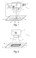
Fig. 2 eine schematische Darstellung einer zweiten Ausführungsform eines erfindungsgemäßen optischen Messsystems; -
Fig. 3 eine schematische Darstellung einer dritten Ausführungsform eines erfindungsgemäßen optischen Messsystems; und -
Fig. 4 eine schematische Darstellung einer vierten Ausführungsform eines erfindungsgemäßen optischen Messsystems.
-
Fig. 1 a schematic representation of a first embodiment of an optical measuring system according to the invention; -
Fig. 2 a schematic representation of a second embodiment of an optical measuring system according to the invention; -
Fig. 3 a schematic representation of a third embodiment of an optical measuring system according to the invention; and -
Fig. 4 a schematic representation of a fourth embodiment of an optical measuring system according to the invention.
Zunächst wird auf
In dieser Ausführungsform des optischen Messsystems 1 ist eine Zusatzlichtquelle 8 vorgesehen, mit der ein zweiter schmaler Lichtstrahl 9 erzeugt wird, der, gegebenenfalls mittels nicht dargestellter optischer Einrichtungen wie Linsen, Spiegel etc. schräg zum ersten Lichtstrahl 5 in das Messfeld 7 projiziert wird, wobei der erste und der zweite Lichtstrahl 5, 9 so ausgerichtet sind, dass sie einander in der Brennebene 3b der abbildenden Optik 3 schneiden. Die Brennebene 3b fällt hier mit der Ebene des Messfeldes 7 zusammen. Somit produziert der zweite Lichtstrahl 9 einen Leuchtfleck 9a, der in der Brennebene 3b mit der visuellen Markierung 5a zusammenfällt. Damit ein Benutzer leichter erkennen kann, welcher Leuchtfleck von welchem Lichtstrahl erzeugt wird, ist es zweckmäßig, wenn der erste Lichtstrahl 5 und der zweite Lichtstrahl 9 unterschiedliche Farben aufweisen.In this embodiment of the
Die Positionierung des Messfelds 7 bzw. eines nicht dargestellten, im Messfeld 7 angeordneten Prüflings, kann anhand der vorhin beschriebenen Vorgangsweise des in Übereinklang Bringens der beiden Leuchtflecken händisch erfolgen. Sie kann aber auch durch das Vorsehen einer Kamera 10 erleichtert werden, wodurch der Benutzer über das auf einem Monitor dargestellte Kamerabild mitverfolgen kann, ob die beiden Leuchtpunkte 5a, 9a zusammenfallen und damit das Messfeld 7 mit der Brennebene 3b in Einklang gebracht worden ist. In einer fortgeschrittenen Ausführung werden die von der Kamera 10 aufgenommenen Kamerabilder Bildverarbeitungsmitteln 11 zugeführt, die die Kamerabilder in Bezug auf die Größe und/oder Fokussierung und/oder relative Position der visuellen Markierung 5a bezogen auf eine Referenzposition auswerten und vorzugsweise auch gleich eine Prüflings-Positioniereinrichtung 12 gemäß der Auswertung der Kamerabilder ansteuern.The positioning of the measuring
In einer Variante der ersten Ausführungsform der Erfindung wird entweder der erste Lichtstrahl 5 leicht schräg zur optischen Achse 3a der abbildenden Optik 3 gestellt oder nur der zweite Lichtstrahl 9 zur Positionierung des Messfelds 7 bzw. eines darauf angeordneten Prüflings verwendet. Bei dieser Anordnung des Messsystems 1 kann aus dem Versatz des Schwerpunktes der visuellen Markierung 5a oder des Leuchtflecks 9a zum Hauptpunkt des Kamerabildes (das ist jener Punkt, wo ein Objektpunkt, der auf der optischen Achse liegt, im Kamerabild abgebildet wird) der Abstand zwischen der Brennebene 3b der abbildenden Optik und dem Messfeld 7 bzw. dem darauf positionierten Prüfling berechnet werden. Damit kann die Positionierung des Prüflings in der Brennebene 3b des Messsystems 1 noch gezielter erfolgen.In a variant of the first embodiment of the invention, either the
Es sei erwähnt, dass anstelle des Vorsehens einer Zusatzlichtquelle 8 zur Erzeugung des zweiten Lichtstrahls 9 auch die erste Lichtquelle 4, gegebenenfalls mit Lichtleitmitteln, wie Strahlenspaltern und Spiegeln, zur Erzeugung des zweiten Lichtstrahls 9 herangezogen werden könnte.
-
Fig. 2 zeigt schematisch eine zweite Ausführungsform eines erfinderischen optischen Messsystem 1'. Diese zweite Ausführungsform unterscheidet sich von der ersten Ausführungsform nur insofern, als dervon der Lichtquelle 4, z.B. einem Laser oder einer Leuchtdiode, erzeugte Lichtstrahl 5' so geformt ist, dass die von ihm generierte visuelle Markierung 5b den Umriss des Messfeldes 7 anzeigt. Die übrigen Teile der zweiten Ausführungsform des optischen Messsystem 1' entsprechen jenen der ersten Ausführungsform und sind auch mit denselben Bezugszeichen versehen. Zu ihrer Erläuterung sei auf die obige Beschreibung der ersten Ausführungsform des optischen Messsystem 1 verwiesen. -
Fig. 3 zeigt schematisch eine dritte Ausführungsform eines erfinderischen optischen Messsystem 1". Diese dritte Ausführungsform unterscheidet sich von der ersten und der zweiten Ausführungsform nur insofern, als dervon der Lichtquelle 4erzeugte Lichtstrahl 5" mit Hilfe einer optischen Maske 6', z.B. einer binären Chrommaske auf einem Glassubstrat, die von der Lichtquelle 4 - ähnlich einem Dia - von hinten durchleuchtet wird, ein Lichtmusterals visuelle Markierung 5c indas Messfeld 7 projiziert. Das so projizierte Lichtmuster markiert für den Benutzerersichtlich das Messfeld 7 desMesssystems 1".Die visuelle Markierung 5c, d.h. das Lichtmuster ist inder Brennebene 3b des Messsystems 1" scharf abgebildet, so dass auch eine vertikale Ausrichtung durch Fokussieren des Musters aufdas Messfeld 7 möglich ist. Auch hier ist - wie in der ersten Ausführungsform des Messsystems leine automatisierte Auswertung dieses Musters über ein Kamerabild realisierbar, mit der eine automatisierte Fokussierung über ein Positioniersystem geschaffen wird. Die übrigen Teile der dritten Ausführungsform des optischen Messsystem 1" entsprechen jenen der ersten Ausführungsform und sind auch mit denselben Bezugszeichen versehen. Zu ihrer Erläuterung sei auf die obige Beschreibung der ersten Ausführungsform des optischen Messsystem 1 verwiesen. -
Fig. 4 zeigt schematisch eine vierte Ausführungsform eines erfinderischen optischen Messsystem 1"', bei der dieLichtquelle 4 einen konvergenten Lichtstrahl 5"' aussendet, derals visuelle Markierung 5d in Form eines Leuchtflecks aufdas Messfeld 7 projiziert wird.Der Lichtstrahl 5"' ist koaxial zur optischen Achse 3a der abbildenden Optik 3 indas Messfeld 7 gerichtet und ist inder Brennebene 3b der abbildenden Optik 3 maximal fokussiert. In der Darstellung vonFig. 4 fällt dieBrennebene 3bmit dem Messfeld 7 zusammen, das heißt, die Einstellung der relativen vertikalen Position zwischen abbildender Optik 3 und Messfeld 7 ist optimal fokussiert. Gleichzeitig weist der Leuchtfleck der visuellenMarkierung 5d seinen geringsten Durchmesser auf. Die Größe der visuellen Markierung kann wie inFig. 1 gezeigt und oben anhand der ersten Ausführungsform beschrieben über eine im Messsystem verbaute Kamera oder auch über eine externe Kamera an einem Monitor verfolgt werden oder mittels einer Bildverarbeitungssoftware ausgewertet werden, die auch eine Prüflings-Positioniermechanik des Messsystems oder eine Messsystem-Positioniermechanik ansteuert. Auch die Richtung, in die man die Positioniermechanik bewegen muss, um den Fokusbereich zu erreichen, kann beim optischen Messsystem 1"' leicht ermittelt werden. Wenn man z.B. das Messsystem 1'" aufdas Messfeld 7 zu bewegt und die Größe der visuellen Markierung 5d abnimmt, so stimmt die Bewegungsrichtung hin zum Fokusbereich, andernfalls muss die Richtung umgekehrt werden.
-
Fig. 2 schematically shows a second embodiment of an inventive optical measuring system 1 '. This second embodiment differs from the first embodiment only insofar as the light beam 5 'generated by thelight source 4, for example a laser or a light emitting diode, is shaped so that thevisual marking 5b generated by it indicates the outline of the measuringfield 7. The remaining parts of the second embodiment of the optical measuring system 1 'correspond to those of the first embodiment and are also provided with the same reference numerals. For explanation, reference is made to the above description of the first embodiment of theoptical measuring system 1. -
Fig. 3 schematically shows a third embodiment of an inventiveoptical measuring system 1 ". This third embodiment differs from the first and the second embodiment only insofar as thelight beam 5 generated by thelight source 4" with the aid of an optical mask 6 ', for example a binary chrome mask on a glass substrate which is illuminated from thelight source 4, similar to a slide, from behind, projects a light pattern as avisual mark 5c into the measuringfield 7. The light pattern projected in this way clearly marks the measuringfield 7 of themeasuring system 1 "for the user. Thevisual marking 5c, ie the light pattern, is sharply imaged in thefocal plane 3b of themeasuring system 1", so that vertical alignment is achieved by focusing the pattern on the measuringfield 7 is possible. Again, as in the first embodiment of the measuring system leash automated evaluation of this pattern on a camera image can be realized with the automated focusing on a positioning system is created. The remaining parts of the third embodiment of theoptical measuring system 1 " correspond to those of the first embodiment and are also provided with the same reference numerals. For explanation, reference is made to the above description of the first embodiment of theoptical measuring system 1. -
Fig. 4 schematically shows a fourth embodiment of an inventiveoptical measuring system 1 "', in which thelight source 4 emits a convergentlight beam 5"', which is projected as avisual mark 5d in the form of a light spot on the measuringfield 7. Thelight beam 5 "'is directed coaxially to theoptical axis 3a of the imagingoptical system 3 into the measuringfield 7 and is maximally focused in thefocal plane 3b of the imagingoptical system 3. In the illustration of FIGFig. 4 If thefocal plane 3b coincides with the measuringfield 7, that is, the setting of the relative vertical position between theimaging optics 3 and the measuringfield 7 is optimally focused. At the same time, the light spot of thevisual mark 5d has its smallest diameter. The size of the visual marker may be as inFig. 1 shown and described above with reference to the first embodiment are tracked via a built-in measuring system camera or via an external camera on a monitor or evaluated by means of image processing software, which also controls a DUT-positioning of the measuring system or a measuring system positioning. The direction in which the positioning mechanism has to be moved in order to reach the focus area can also be easily determined in theoptical measuring system 1 ", for example if the measuring system 1 '" moves toward the measuringfield 7 and the size of thevisual marking 5d decreases, so the direction of movement is right to the focus area, otherwise the direction must be reversed.
In einer Variante der vierten Ausführungsform des Messsystems 1'" ist der konvergente Lichtstrahl 5"' schräg zur optischen Achse 3a der abbildenden Optik 3 in das Messfeld 7 gerichtet.In a variant of the fourth embodiment of the
Die übrigen Teile der vierten Ausführungsform des optischen Messsystem 1'" entsprechen jenen der ersten Ausführungsform und sind auch mit denselben Bezugszeichen versehen. Zu ihrer Erläuterung sei auf die obige Beschreibung der ersten Ausführungsform des optischen Messsystem 1 verwiesen.The other parts of the fourth embodiment of the optical measuring system 1 '"correspond to those of the first embodiment and are also given the same reference numerals, and for explanation, reference is made to the above description of the first embodiment of the
Claims (14)
Priority Applications (1)
| Application Number | Priority Date | Filing Date | Title |
|---|---|---|---|
| EP11191963.5A EP2602584A1 (en) | 2011-12-05 | 2011-12-05 | Optical measuring system |
Applications Claiming Priority (1)
| Application Number | Priority Date | Filing Date | Title |
|---|---|---|---|
| EP11191963.5A EP2602584A1 (en) | 2011-12-05 | 2011-12-05 | Optical measuring system |
Publications (1)
| Publication Number | Publication Date |
|---|---|
| EP2602584A1 true EP2602584A1 (en) | 2013-06-12 |
Family
ID=45372212
Family Applications (1)
| Application Number | Title | Priority Date | Filing Date |
|---|---|---|---|
| EP11191963.5A Withdrawn EP2602584A1 (en) | 2011-12-05 | 2011-12-05 | Optical measuring system |
Country Status (1)
| Country | Link |
|---|---|
| EP (1) | EP2602584A1 (en) |
Cited By (2)
| Publication number | Priority date | Publication date | Assignee | Title |
|---|---|---|---|---|
| CN107421473A (en) * | 2017-05-26 | 2017-12-01 | 南京理工大学 | The two beam laser coaxial degree detection methods based on image procossing |
| CN111536872A (en) * | 2020-05-12 | 2020-08-14 | 河北工业大学 | Two-dimensional plane distance measuring device and method based on vision and mark point identification device |
Citations (7)
| Publication number | Priority date | Publication date | Assignee | Title |
|---|---|---|---|---|
| US5196900A (en) * | 1988-04-12 | 1993-03-23 | Metronor A.S. | Method and sensor for opto-electronic angle measurements |
| JPH05205097A (en) * | 1992-01-28 | 1993-08-13 | Nippon Dry Chem Co Ltd | Image input device and input method |
| DE10037771A1 (en) * | 2000-08-03 | 2002-02-21 | Fraunhofer Ges Forschung | Object distance measurement method in endoscopy and industrial automation, involves moving scanners, such that beams irradiated on object converge at one measurement point |
| EP1262810A2 (en) * | 2001-05-29 | 2002-12-04 | Leica Microsystems AG | Method of distance measurement of extended objects with an optical viewing device and microscope applying it |
| US20050237581A1 (en) * | 2004-04-21 | 2005-10-27 | Knighton Mark S | Hand held portable three dimensional scanner |
| US20080107309A1 (en) * | 2006-11-03 | 2008-05-08 | Cerni Consulting, Llc | Method and apparatus for biometric identification |
| FR2940423A1 (en) * | 2008-12-22 | 2010-06-25 | Noomeo | DENSE RECONSTRUCTION THREE-DIMENSIONAL SCANNING DEVICE |
-
2011
- 2011-12-05 EP EP11191963.5A patent/EP2602584A1/en not_active Withdrawn
Patent Citations (7)
| Publication number | Priority date | Publication date | Assignee | Title |
|---|---|---|---|---|
| US5196900A (en) * | 1988-04-12 | 1993-03-23 | Metronor A.S. | Method and sensor for opto-electronic angle measurements |
| JPH05205097A (en) * | 1992-01-28 | 1993-08-13 | Nippon Dry Chem Co Ltd | Image input device and input method |
| DE10037771A1 (en) * | 2000-08-03 | 2002-02-21 | Fraunhofer Ges Forschung | Object distance measurement method in endoscopy and industrial automation, involves moving scanners, such that beams irradiated on object converge at one measurement point |
| EP1262810A2 (en) * | 2001-05-29 | 2002-12-04 | Leica Microsystems AG | Method of distance measurement of extended objects with an optical viewing device and microscope applying it |
| US20050237581A1 (en) * | 2004-04-21 | 2005-10-27 | Knighton Mark S | Hand held portable three dimensional scanner |
| US20080107309A1 (en) * | 2006-11-03 | 2008-05-08 | Cerni Consulting, Llc | Method and apparatus for biometric identification |
| FR2940423A1 (en) * | 2008-12-22 | 2010-06-25 | Noomeo | DENSE RECONSTRUCTION THREE-DIMENSIONAL SCANNING DEVICE |
Cited By (2)
| Publication number | Priority date | Publication date | Assignee | Title |
|---|---|---|---|---|
| CN107421473A (en) * | 2017-05-26 | 2017-12-01 | 南京理工大学 | The two beam laser coaxial degree detection methods based on image procossing |
| CN111536872A (en) * | 2020-05-12 | 2020-08-14 | 河北工业大学 | Two-dimensional plane distance measuring device and method based on vision and mark point identification device |
Similar Documents
| Publication | Publication Date | Title |
|---|---|---|
| DE102005022095B4 (en) | Method and device for determining a lateral relative movement between a machining head and a workpiece | |
| DE102013227101B3 (en) | Optical system for tracking a target | |
| DE102011016519B4 (en) | Device for processing a workpiece by means of a high-energy machining beam | |
| EP2847540B1 (en) | Improved illumination module for a co-ordinate measuring machine | |
| DE102014108353A1 (en) | Method and device for the determination of geometries on measured objects by means of a combined sensor system | |
| EP2131145B1 (en) | Optical monitoring device | |
| DE4136002A1 (en) | MOIRE CONTOUR IMAGING DEVICE | |
| EP2582284A2 (en) | Method and device for determining eye position | |
| EP3581881A1 (en) | Surface measurement by means of excited fluorescence | |
| WO2015036026A1 (en) | Method and apparatus for measuring internal threads of a workpiece having an optical sensor | |
| WO2019120557A1 (en) | Optical device for automatically applying or producing and monitoring a structure applied to a substrate with determination of geometric dimensions, and corresponding method | |
| WO2015128353A1 (en) | Method and device for optically determining a distance | |
| DE102019120398B3 (en) | Laser processing system and method for a central alignment of a laser beam in a processing head of a laser processing system | |
| DE102015109960B4 (en) | Apparatus and method for optically determining a position and / or orientation of a manipulator | |
| DE102017211680A1 (en) | Optical sensor and method for positioning, focusing and illumination | |
| EP3303990B1 (en) | Lighting control when using optical measuring devices | |
| EP2602584A1 (en) | Optical measuring system | |
| DE102011052586B4 (en) | Embossing head with positioning aid | |
| EP1960156A1 (en) | Device and method for visualizing positions on a surface | |
| DE102013202349B3 (en) | Coherence grid interferometer and method for spatially resolved optical measurement of the height geometry data of an object | |
| DE102006005874A1 (en) | Contactless cylinder measurement unit has lamps generating lines on surface and orthogonal shadows for multiple line triangulation | |
| DE4217430A1 (en) | Pick=up arrangement for detecting and representing objects for comparison - has electronic camera and prismatic deflection devices forming partial images of simultaneously detected object regions | |
| EP3066415B1 (en) | Coordinate measuring machine with an optical sensor and an improved illumination module | |
| EP1136787B1 (en) | Object projection with distance compensation ( size, color ) | |
| DE102017009334B3 (en) | Method for testing an optical system |
Legal Events
| Date | Code | Title | Description |
|---|---|---|---|
| PUAI | Public reference made under article 153(3) epc to a published international application that has entered the european phase |
Free format text: ORIGINAL CODE: 0009012 |
|
| AK | Designated contracting states |
Kind code of ref document: A1 Designated state(s): AL AT BE BG CH CY CZ DE DK EE ES FI FR GB GR HR HU IE IS IT LI LT LU LV MC MK MT NL NO PL PT RO RS SE SI SK SM TR |
|
| AX | Request for extension of the european patent |
Extension state: BA ME |
|
| STAA | Information on the status of an ep patent application or granted ep patent |
Free format text: STATUS: THE APPLICATION IS DEEMED TO BE WITHDRAWN |
|
| 18D | Application deemed to be withdrawn |
Effective date: 20131213 |