EP2599611A2 - Fluid system having an expandable pump chamber - Google Patents
Fluid system having an expandable pump chamber Download PDFInfo
- Publication number
- EP2599611A2 EP2599611A2 EP13155664.9A EP13155664A EP2599611A2 EP 2599611 A2 EP2599611 A2 EP 2599611A2 EP 13155664 A EP13155664 A EP 13155664A EP 2599611 A2 EP2599611 A2 EP 2599611A2
- Authority
- EP
- European Patent Office
- Prior art keywords
- pump chamber
- fluid
- layers
- fluid system
- layer
- Prior art date
- Legal status (The legal status is an assumption and is not a legal conclusion. Google has not performed a legal analysis and makes no representation as to the accuracy of the status listed.)
- Granted
Links
- 239000012530 fluid Substances 0.000 title claims abstract description 487
- 239000000463 material Substances 0.000 claims description 75
- 229920000642 polymer Polymers 0.000 claims description 27
- 238000000034 method Methods 0.000 claims description 23
- 238000004891 communication Methods 0.000 claims description 20
- 230000000903 blocking effect Effects 0.000 claims description 17
- 239000002861 polymer material Substances 0.000 claims description 13
- 239000006261 foam material Substances 0.000 claims description 12
- 238000004519 manufacturing process Methods 0.000 claims description 9
- 239000003570 air Substances 0.000 description 25
- 239000000758 substrate Substances 0.000 description 21
- 239000012080 ambient air Substances 0.000 description 20
- 210000002683 foot Anatomy 0.000 description 17
- 238000006243 chemical reaction Methods 0.000 description 12
- 230000008569 process Effects 0.000 description 11
- 230000007704 transition Effects 0.000 description 11
- 239000006260 foam Substances 0.000 description 9
- 210000000474 heel Anatomy 0.000 description 9
- 238000007906 compression Methods 0.000 description 8
- 230000006835 compression Effects 0.000 description 8
- 210000004744 fore-foot Anatomy 0.000 description 8
- 230000008901 benefit Effects 0.000 description 7
- 238000012546 transfer Methods 0.000 description 7
- 230000004888 barrier function Effects 0.000 description 6
- 229920001343 polytetrafluoroethylene Polymers 0.000 description 6
- 239000004810 polytetrafluoroethylene Substances 0.000 description 6
- 229920002635 polyurethane Polymers 0.000 description 6
- 239000004814 polyurethane Substances 0.000 description 6
- XLYOFNOQVPJJNP-UHFFFAOYSA-N water Substances O XLYOFNOQVPJJNP-UHFFFAOYSA-N 0.000 description 6
- 239000004433 Thermoplastic polyurethane Substances 0.000 description 5
- 238000010438 heat treatment Methods 0.000 description 5
- 238000003856 thermoforming Methods 0.000 description 5
- 229920002803 thermoplastic polyurethane Polymers 0.000 description 5
- 239000011800 void material Substances 0.000 description 5
- 230000000386 athletic effect Effects 0.000 description 4
- 210000000459 calcaneus Anatomy 0.000 description 4
- 230000007423 decrease Effects 0.000 description 4
- 230000003247 decreasing effect Effects 0.000 description 4
- 239000013536 elastomeric material Substances 0.000 description 4
- -1 polytetrafluoroethylene Polymers 0.000 description 4
- 229920000219 Ethylene vinyl alcohol Polymers 0.000 description 3
- 239000011324 bead Substances 0.000 description 3
- 238000000071 blow moulding Methods 0.000 description 3
- BFMKFCLXZSUVPI-UHFFFAOYSA-N ethyl but-3-enoate Chemical compound CCOC(=O)CC=C BFMKFCLXZSUVPI-UHFFFAOYSA-N 0.000 description 3
- 239000010985 leather Substances 0.000 description 3
- 229920000728 polyester Polymers 0.000 description 3
- 239000004753 textile Substances 0.000 description 3
- 229920002725 thermoplastic elastomer Polymers 0.000 description 3
- 230000009471 action Effects 0.000 description 2
- 238000004026 adhesive bonding Methods 0.000 description 2
- 230000015556 catabolic process Effects 0.000 description 2
- 229920000295 expanded polytetrafluoroethylene Polymers 0.000 description 2
- 238000007373 indentation Methods 0.000 description 2
- 239000007788 liquid Substances 0.000 description 2
- 230000036961 partial effect Effects 0.000 description 2
- 230000004043 responsiveness Effects 0.000 description 2
- 238000001175 rotational moulding Methods 0.000 description 2
- 239000000126 substance Substances 0.000 description 2
- 229920001169 thermoplastic Polymers 0.000 description 2
- 239000004416 thermosoftening plastic Substances 0.000 description 2
- 229920002799 BoPET Polymers 0.000 description 1
- JOYRKODLDBILNP-UHFFFAOYSA-N Ethyl urethane Chemical compound CCOC(N)=O JOYRKODLDBILNP-UHFFFAOYSA-N 0.000 description 1
- 239000005041 Mylar™ Substances 0.000 description 1
- 239000002033 PVDF binder Substances 0.000 description 1
- 239000004698 Polyethylene Substances 0.000 description 1
- 239000004721 Polyphenylene oxide Substances 0.000 description 1
- 239000004743 Polypropylene Substances 0.000 description 1
- 239000004699 Ultra-high molecular weight polyethylene Substances 0.000 description 1
- 238000005299 abrasion Methods 0.000 description 1
- 230000005540 biological transmission Effects 0.000 description 1
- 230000015572 biosynthetic process Effects 0.000 description 1
- 239000000919 ceramic Substances 0.000 description 1
- 238000000576 coating method Methods 0.000 description 1
- 230000001010 compromised effect Effects 0.000 description 1
- 238000005260 corrosion Methods 0.000 description 1
- 230000007797 corrosion Effects 0.000 description 1
- 230000001419 dependent effect Effects 0.000 description 1
- 238000013461 design Methods 0.000 description 1
- 230000001627 detrimental effect Effects 0.000 description 1
- 238000009472 formulation Methods 0.000 description 1
- 229920001903 high density polyethylene Polymers 0.000 description 1
- 239000004700 high-density polyethylene Substances 0.000 description 1
- 230000007062 hydrolysis Effects 0.000 description 1
- 238000006460 hydrolysis reaction Methods 0.000 description 1
- 230000002401 inhibitory effect Effects 0.000 description 1
- 230000007246 mechanism Effects 0.000 description 1
- 210000000452 mid-foot Anatomy 0.000 description 1
- 239000000203 mixture Substances 0.000 description 1
- 238000012986 modification Methods 0.000 description 1
- 230000004048 modification Effects 0.000 description 1
- 229920000570 polyether Polymers 0.000 description 1
- 229920000573 polyethylene Polymers 0.000 description 1
- 229920001155 polypropylene Polymers 0.000 description 1
- 229920001296 polysiloxane Polymers 0.000 description 1
- 239000004800 polyvinyl chloride Substances 0.000 description 1
- 229920000915 polyvinyl chloride Polymers 0.000 description 1
- 229920002981 polyvinylidene fluoride Polymers 0.000 description 1
- 239000011148 porous material Substances 0.000 description 1
- 230000001105 regulatory effect Effects 0.000 description 1
- 230000003252 repetitive effect Effects 0.000 description 1
- 238000007493 shaping process Methods 0.000 description 1
- 239000007787 solid Substances 0.000 description 1
- 238000010561 standard procedure Methods 0.000 description 1
- 229920005992 thermoplastic resin Polymers 0.000 description 1
- 238000012549 training Methods 0.000 description 1
- 229920000785 ultra high molecular weight polyethylene Polymers 0.000 description 1
- 238000003466 welding Methods 0.000 description 1
Images


Classifications
-
- A—HUMAN NECESSITIES
- A43—FOOTWEAR
- A43B—CHARACTERISTIC FEATURES OF FOOTWEAR; PARTS OF FOOTWEAR
- A43B13/00—Soles; Sole-and-heel integral units
- A43B13/14—Soles; Sole-and-heel integral units characterised by the constructive form
- A43B13/18—Resilient soles
- A43B13/20—Pneumatic soles filled with a compressible fluid, e.g. air, gas
- A43B13/203—Pneumatic soles filled with a compressible fluid, e.g. air, gas provided with a pump or valve
-
- A—HUMAN NECESSITIES
- A43—FOOTWEAR
- A43B—CHARACTERISTIC FEATURES OF FOOTWEAR; PARTS OF FOOTWEAR
- A43B1/00—Footwear characterised by the material
- A43B1/0018—Footwear characterised by the material made at least partially of flexible, bellow-like shaped material
-
- B—PERFORMING OPERATIONS; TRANSPORTING
- B29—WORKING OF PLASTICS; WORKING OF SUBSTANCES IN A PLASTIC STATE IN GENERAL
- B29C—SHAPING OR JOINING OF PLASTICS; SHAPING OF MATERIAL IN A PLASTIC STATE, NOT OTHERWISE PROVIDED FOR; AFTER-TREATMENT OF THE SHAPED PRODUCTS, e.g. REPAIRING
- B29C65/00—Joining or sealing of preformed parts, e.g. welding of plastics materials; Apparatus therefor
- B29C65/02—Joining or sealing of preformed parts, e.g. welding of plastics materials; Apparatus therefor by heating, with or without pressure
-
- B—PERFORMING OPERATIONS; TRANSPORTING
- B29—WORKING OF PLASTICS; WORKING OF SUBSTANCES IN A PLASTIC STATE IN GENERAL
- B29C—SHAPING OR JOINING OF PLASTICS; SHAPING OF MATERIAL IN A PLASTIC STATE, NOT OTHERWISE PROVIDED FOR; AFTER-TREATMENT OF THE SHAPED PRODUCTS, e.g. REPAIRING
- B29C66/00—General aspects of processes or apparatus for joining preformed parts
- B29C66/01—General aspects dealing with the joint area or with the area to be joined
- B29C66/05—Particular design of joint configurations
- B29C66/10—Particular design of joint configurations particular design of the joint cross-sections
- B29C66/11—Joint cross-sections comprising a single joint-segment, i.e. one of the parts to be joined comprising a single joint-segment in the joint cross-section
- B29C66/112—Single lapped joints
- B29C66/1122—Single lap to lap joints, i.e. overlap joints
-
- B—PERFORMING OPERATIONS; TRANSPORTING
- B29—WORKING OF PLASTICS; WORKING OF SUBSTANCES IN A PLASTIC STATE IN GENERAL
- B29C—SHAPING OR JOINING OF PLASTICS; SHAPING OF MATERIAL IN A PLASTIC STATE, NOT OTHERWISE PROVIDED FOR; AFTER-TREATMENT OF THE SHAPED PRODUCTS, e.g. REPAIRING
- B29C66/00—General aspects of processes or apparatus for joining preformed parts
- B29C66/01—General aspects dealing with the joint area or with the area to be joined
- B29C66/05—Particular design of joint configurations
- B29C66/20—Particular design of joint configurations particular design of the joint lines, e.g. of the weld lines
- B29C66/24—Particular design of joint configurations particular design of the joint lines, e.g. of the weld lines said joint lines being closed or non-straight
- B29C66/242—Particular design of joint configurations particular design of the joint lines, e.g. of the weld lines said joint lines being closed or non-straight said joint lines being closed, i.e. forming closed contours
-
- B—PERFORMING OPERATIONS; TRANSPORTING
- B29—WORKING OF PLASTICS; WORKING OF SUBSTANCES IN A PLASTIC STATE IN GENERAL
- B29C—SHAPING OR JOINING OF PLASTICS; SHAPING OF MATERIAL IN A PLASTIC STATE, NOT OTHERWISE PROVIDED FOR; AFTER-TREATMENT OF THE SHAPED PRODUCTS, e.g. REPAIRING
- B29C66/00—General aspects of processes or apparatus for joining preformed parts
- B29C66/01—General aspects dealing with the joint area or with the area to be joined
- B29C66/346—Making joints having variable thicknesses in the joint area, e.g. by using jaws having an adapted configuration
-
- B—PERFORMING OPERATIONS; TRANSPORTING
- B29—WORKING OF PLASTICS; WORKING OF SUBSTANCES IN A PLASTIC STATE IN GENERAL
- B29C—SHAPING OR JOINING OF PLASTICS; SHAPING OF MATERIAL IN A PLASTIC STATE, NOT OTHERWISE PROVIDED FOR; AFTER-TREATMENT OF THE SHAPED PRODUCTS, e.g. REPAIRING
- B29C66/00—General aspects of processes or apparatus for joining preformed parts
- B29C66/40—General aspects of joining substantially flat articles, e.g. plates, sheets or web-like materials; Making flat seams in tubular or hollow articles; Joining single elements to substantially flat surfaces
- B29C66/41—Joining substantially flat articles ; Making flat seams in tubular or hollow articles
- B29C66/43—Joining a relatively small portion of the surface of said articles
-
- F—MECHANICAL ENGINEERING; LIGHTING; HEATING; WEAPONS; BLASTING
- F04—POSITIVE - DISPLACEMENT MACHINES FOR LIQUIDS; PUMPS FOR LIQUIDS OR ELASTIC FLUIDS
- F04B—POSITIVE-DISPLACEMENT MACHINES FOR LIQUIDS; PUMPS
- F04B45/00—Pumps or pumping installations having flexible working members and specially adapted for elastic fluids
-
- B—PERFORMING OPERATIONS; TRANSPORTING
- B29—WORKING OF PLASTICS; WORKING OF SUBSTANCES IN A PLASTIC STATE IN GENERAL
- B29C—SHAPING OR JOINING OF PLASTICS; SHAPING OF MATERIAL IN A PLASTIC STATE, NOT OTHERWISE PROVIDED FOR; AFTER-TREATMENT OF THE SHAPED PRODUCTS, e.g. REPAIRING
- B29C65/00—Joining or sealing of preformed parts, e.g. welding of plastics materials; Apparatus therefor
- B29C65/02—Joining or sealing of preformed parts, e.g. welding of plastics materials; Apparatus therefor by heating, with or without pressure
- B29C65/14—Joining or sealing of preformed parts, e.g. welding of plastics materials; Apparatus therefor by heating, with or without pressure using wave energy, i.e. electromagnetic radiation, or particle radiation
- B29C65/1403—Joining or sealing of preformed parts, e.g. welding of plastics materials; Apparatus therefor by heating, with or without pressure using wave energy, i.e. electromagnetic radiation, or particle radiation characterised by the type of electromagnetic or particle radiation
- B29C65/1412—Infrared [IR] radiation
-
- B—PERFORMING OPERATIONS; TRANSPORTING
- B29—WORKING OF PLASTICS; WORKING OF SUBSTANCES IN A PLASTIC STATE IN GENERAL
- B29C—SHAPING OR JOINING OF PLASTICS; SHAPING OF MATERIAL IN A PLASTIC STATE, NOT OTHERWISE PROVIDED FOR; AFTER-TREATMENT OF THE SHAPED PRODUCTS, e.g. REPAIRING
- B29C65/00—Joining or sealing of preformed parts, e.g. welding of plastics materials; Apparatus therefor
- B29C65/02—Joining or sealing of preformed parts, e.g. welding of plastics materials; Apparatus therefor by heating, with or without pressure
- B29C65/14—Joining or sealing of preformed parts, e.g. welding of plastics materials; Apparatus therefor by heating, with or without pressure using wave energy, i.e. electromagnetic radiation, or particle radiation
- B29C65/16—Laser beams
-
- B—PERFORMING OPERATIONS; TRANSPORTING
- B29—WORKING OF PLASTICS; WORKING OF SUBSTANCES IN A PLASTIC STATE IN GENERAL
- B29C—SHAPING OR JOINING OF PLASTICS; SHAPING OF MATERIAL IN A PLASTIC STATE, NOT OTHERWISE PROVIDED FOR; AFTER-TREATMENT OF THE SHAPED PRODUCTS, e.g. REPAIRING
- B29C66/00—General aspects of processes or apparatus for joining preformed parts
- B29C66/004—Preventing sticking together, e.g. of some areas of the parts to be joined
-
- B—PERFORMING OPERATIONS; TRANSPORTING
- B29—WORKING OF PLASTICS; WORKING OF SUBSTANCES IN A PLASTIC STATE IN GENERAL
- B29C—SHAPING OR JOINING OF PLASTICS; SHAPING OF MATERIAL IN A PLASTIC STATE, NOT OTHERWISE PROVIDED FOR; AFTER-TREATMENT OF THE SHAPED PRODUCTS, e.g. REPAIRING
- B29C66/00—General aspects of processes or apparatus for joining preformed parts
- B29C66/01—General aspects dealing with the joint area or with the area to be joined
- B29C66/32—Measures for keeping the burr form under control; Avoiding burr formation; Shaping the burr
- B29C66/328—Leaving the burrs unchanged for providing particular properties to the joint, e.g. as decorative effect
- B29C66/3282—Leaving the burrs unchanged for providing particular properties to the joint, e.g. as decorative effect for reinforcing the joint
-
- B—PERFORMING OPERATIONS; TRANSPORTING
- B29—WORKING OF PLASTICS; WORKING OF SUBSTANCES IN A PLASTIC STATE IN GENERAL
- B29C—SHAPING OR JOINING OF PLASTICS; SHAPING OF MATERIAL IN A PLASTIC STATE, NOT OTHERWISE PROVIDED FOR; AFTER-TREATMENT OF THE SHAPED PRODUCTS, e.g. REPAIRING
- B29C66/00—General aspects of processes or apparatus for joining preformed parts
- B29C66/01—General aspects dealing with the joint area or with the area to be joined
- B29C66/345—Progressively making the joint, e.g. starting from the middle
- B29C66/3452—Making complete joints by combining partial joints
-
- B—PERFORMING OPERATIONS; TRANSPORTING
- B29—WORKING OF PLASTICS; WORKING OF SUBSTANCES IN A PLASTIC STATE IN GENERAL
- B29C—SHAPING OR JOINING OF PLASTICS; SHAPING OF MATERIAL IN A PLASTIC STATE, NOT OTHERWISE PROVIDED FOR; AFTER-TREATMENT OF THE SHAPED PRODUCTS, e.g. REPAIRING
- B29C66/00—General aspects of processes or apparatus for joining preformed parts
- B29C66/40—General aspects of joining substantially flat articles, e.g. plates, sheets or web-like materials; Making flat seams in tubular or hollow articles; Joining single elements to substantially flat surfaces
- B29C66/41—Joining substantially flat articles ; Making flat seams in tubular or hollow articles
- B29C66/43—Joining a relatively small portion of the surface of said articles
- B29C66/431—Joining the articles to themselves
- B29C66/4312—Joining the articles to themselves for making flat seams in tubular or hollow articles, e.g. transversal seams
-
- B—PERFORMING OPERATIONS; TRANSPORTING
- B29—WORKING OF PLASTICS; WORKING OF SUBSTANCES IN A PLASTIC STATE IN GENERAL
- B29C—SHAPING OR JOINING OF PLASTICS; SHAPING OF MATERIAL IN A PLASTIC STATE, NOT OTHERWISE PROVIDED FOR; AFTER-TREATMENT OF THE SHAPED PRODUCTS, e.g. REPAIRING
- B29C66/00—General aspects of processes or apparatus for joining preformed parts
- B29C66/70—General aspects of processes or apparatus for joining preformed parts characterised by the composition, physical properties or the structure of the material of the parts to be joined; Joining with non-plastics material
- B29C66/71—General aspects of processes or apparatus for joining preformed parts characterised by the composition, physical properties or the structure of the material of the parts to be joined; Joining with non-plastics material characterised by the composition of the plastics material of the parts to be joined
-
- B—PERFORMING OPERATIONS; TRANSPORTING
- B29—WORKING OF PLASTICS; WORKING OF SUBSTANCES IN A PLASTIC STATE IN GENERAL
- B29C—SHAPING OR JOINING OF PLASTICS; SHAPING OF MATERIAL IN A PLASTIC STATE, NOT OTHERWISE PROVIDED FOR; AFTER-TREATMENT OF THE SHAPED PRODUCTS, e.g. REPAIRING
- B29C66/00—General aspects of processes or apparatus for joining preformed parts
- B29C66/70—General aspects of processes or apparatus for joining preformed parts characterised by the composition, physical properties or the structure of the material of the parts to be joined; Joining with non-plastics material
- B29C66/72—General aspects of processes or apparatus for joining preformed parts characterised by the composition, physical properties or the structure of the material of the parts to be joined; Joining with non-plastics material characterised by the structure of the material of the parts to be joined
- B29C66/727—General aspects of processes or apparatus for joining preformed parts characterised by the composition, physical properties or the structure of the material of the parts to be joined; Joining with non-plastics material characterised by the structure of the material of the parts to be joined being porous, e.g. foam
-
- B—PERFORMING OPERATIONS; TRANSPORTING
- B29—WORKING OF PLASTICS; WORKING OF SUBSTANCES IN A PLASTIC STATE IN GENERAL
- B29K—INDEXING SCHEME ASSOCIATED WITH SUBCLASSES B29B, B29C OR B29D, RELATING TO MOULDING MATERIALS OR TO MATERIALS FOR MOULDS, REINFORCEMENTS, FILLERS OR PREFORMED PARTS, e.g. INSERTS
- B29K2023/00—Use of polyalkenes or derivatives thereof as moulding material
- B29K2023/04—Polymers of ethylene
- B29K2023/06—PE, i.e. polyethylene
-
- B—PERFORMING OPERATIONS; TRANSPORTING
- B29—WORKING OF PLASTICS; WORKING OF SUBSTANCES IN A PLASTIC STATE IN GENERAL
- B29K—INDEXING SCHEME ASSOCIATED WITH SUBCLASSES B29B, B29C OR B29D, RELATING TO MOULDING MATERIALS OR TO MATERIALS FOR MOULDS, REINFORCEMENTS, FILLERS OR PREFORMED PARTS, e.g. INSERTS
- B29K2027/00—Use of polyvinylhalogenides or derivatives thereof as moulding material
- B29K2027/06—PVC, i.e. polyvinylchloride
-
- B—PERFORMING OPERATIONS; TRANSPORTING
- B29—WORKING OF PLASTICS; WORKING OF SUBSTANCES IN A PLASTIC STATE IN GENERAL
- B29K—INDEXING SCHEME ASSOCIATED WITH SUBCLASSES B29B, B29C OR B29D, RELATING TO MOULDING MATERIALS OR TO MATERIALS FOR MOULDS, REINFORCEMENTS, FILLERS OR PREFORMED PARTS, e.g. INSERTS
- B29K2075/00—Use of PU, i.e. polyureas or polyurethanes or derivatives thereof, as moulding material
-
- B—PERFORMING OPERATIONS; TRANSPORTING
- B29—WORKING OF PLASTICS; WORKING OF SUBSTANCES IN A PLASTIC STATE IN GENERAL
- B29K—INDEXING SCHEME ASSOCIATED WITH SUBCLASSES B29B, B29C OR B29D, RELATING TO MOULDING MATERIALS OR TO MATERIALS FOR MOULDS, REINFORCEMENTS, FILLERS OR PREFORMED PARTS, e.g. INSERTS
- B29K2101/00—Use of unspecified macromolecular compounds as moulding material
- B29K2101/12—Thermoplastic materials
-
- B—PERFORMING OPERATIONS; TRANSPORTING
- B29—WORKING OF PLASTICS; WORKING OF SUBSTANCES IN A PLASTIC STATE IN GENERAL
- B29L—INDEXING SCHEME ASSOCIATED WITH SUBCLASS B29C, RELATING TO PARTICULAR ARTICLES
- B29L2022/00—Hollow articles
- B29L2022/02—Inflatable articles
-
- B—PERFORMING OPERATIONS; TRANSPORTING
- B29—WORKING OF PLASTICS; WORKING OF SUBSTANCES IN A PLASTIC STATE IN GENERAL
- B29L—INDEXING SCHEME ASSOCIATED WITH SUBCLASS B29C, RELATING TO PARTICULAR ARTICLES
- B29L2022/00—Hollow articles
- B29L2022/02—Inflatable articles
- B29L2022/025—Bladders
-
- B—PERFORMING OPERATIONS; TRANSPORTING
- B29—WORKING OF PLASTICS; WORKING OF SUBSTANCES IN A PLASTIC STATE IN GENERAL
- B29L—INDEXING SCHEME ASSOCIATED WITH SUBCLASS B29C, RELATING TO PARTICULAR ARTICLES
- B29L2031/00—Other particular articles
- B29L2031/48—Wearing apparel
- B29L2031/50—Footwear, e.g. shoes or parts thereof
- B29L2031/507—Insoles
-
- B—PERFORMING OPERATIONS; TRANSPORTING
- B29—WORKING OF PLASTICS; WORKING OF SUBSTANCES IN A PLASTIC STATE IN GENERAL
- B29L—INDEXING SCHEME ASSOCIATED WITH SUBCLASS B29C, RELATING TO PARTICULAR ARTICLES
- B29L2031/00—Other particular articles
- B29L2031/748—Machines or parts thereof not otherwise provided for
- B29L2031/7496—Pumps
Definitions
- Conventional articles of athletic footwear include two primary elements, an upper and a sole structure.
- the upper is usually formed from a plurality of elements, such as textiles, foam, and leather materials, that are stitched or adhesively bonded together to form an interior void for securely and comfortably receiving a foot.
- the sole structure incorporates multiple layers that are conventionally referred to as an insole, a midsole, and an outsole.
- the insole is a thin, compressible member located within the upper and adjacent a sole of the foot to enhance comfort.
- the midsole is secured to the upper and forms a middle layer of the sole structure.
- the outsole forms a ground-contacting element of the footwear and is usually fashioned from a durable, wear resistant material that includes texturing to improve traction.
- the primary material forming a conventional midsole is a resilient, polymer foam, such as polyurethane or ethylvinylacetate, that extends throughout a length of the footwear.
- a polymer foam midsole may also incorporate a fluid-filled chamber, having the configuration of a bladder, to enhance ground reaction force attenuation of the sole structure.
- U.S. Patent Number 4,183,156 to Rudy provides an example of a fluid-filled chamber that includes an outer enclosing member formed of an elastomeric material. The outer enclosing material defines a plurality of tubular members in fluid communication with each other.
- the fluid-filled chamber described above may be manufactured by a two-film technique, wherein two separate layers of elastomeric film are formed to have the overall shape of the chamber.
- the layers are then bonded together along their respective peripheries to form an upper surface, a lower surface, and sidewalls of the chamber, and the layers are bonded together at predetermined interior locations to impart a desired shape to the chamber. That is, interior portions of the layers are connected to form subchambers of a predetermined shape and size at desired locations.
- the chamber is subsequently pressurized above ambient pressure by inserting a nozzle or needle, which is connected to a fluid pressure source, into a fill inlet formed in the chamber. After the chamber is pressurized, the nozzle is removed and the fill inlet is sealed.
- Another method of manufacturing a fluid-filled chamber is through a blow-molding process, as generally disclosed in U.S. Patent Number 5,353,459 to Potter et al ., wherein a liquefied elastomeric material is placed in a mold having the desired overall shape and configuration of the bladder.
- the mold has an opening at one location through which pressurized air is provided. The pressurized air forces the liquefied elastomeric material against the inner surfaces of the mold and causes the material to harden in the mold, thereby forming a chamber with the desired shape and configuration.
- fluid-filled chambers may be manufactured through a thermoforming process, as disclosed in U.S.
- Patent Number 5,976,451 to Skaja, et al . wherein a pair of sheets of flexible thermoplastic resin are placed against a pair of molds having a vacuum system for properly shaping the two sheets. The mold portions are then closed to seal the two sheets around their peripheries and form the bladder.
- An article of footwear may also incorporate a fluid system that includes various components, including a pressure chamber, a pump chamber for increasing the pressure in the pressure chamber, one or more valves for regulating the direction and rate of fluid flow, and conduits that connect the various fluid system components.
- U.S. Patent Number 6,457,262 to Swigart discloses a fluid system having a central chamber and two side chambers positioned adjacent central chamber. Each of the side chambers are in fluid communication with the central chamber through at least one conduit that includes a valve. Accordingly, a fluid contained by the fluid system may flow from the central chamber to side chambers, and the fluid may flow from the side chambers to the central chamber. Examples of other fluid systems that are sealed to prevent the entry or exit of ambient air are disclosed in U.S. Patent Numbers 5,950,332 to Lain ; 5,794,361 to Sadler ; and 4,446,634 to Johnson et al ., for example.
- Fluid systems incorporated into an article of footwear may also utilize ambient air as the system fluid.
- U.S. Patent Number 5,826,349 to Goss discloses an article of footwear having a fluid system that utilizes ambient air to ventilate an interior of an upper.
- the fluid system includes an intake positioned on the upper and a conduit leading from the intake to a plurality of chambers that are in fluid communication. Valves associated with the chambers prevent the air from escaping through the intake when the chambers are compressed. Rather, the air is forced out of the chambers through another conduit that leads to the interior of the upper.
- U.S. Patent Number 5,937,462 to Huang disclose a fluid system that utilizes ambient air to pressurize a chamber within a sole structure of an article of footwear.
- One aspect of the invention involves a fluid system having a pump chamber and a pressure chamber that are in fluid communication.
- the pump chamber includes a first pair of layers and a second pair of layers.
- the first pair of layers form opposite surfaces of the pump chamber, and the second pair of layers are positioned between the first pair of layers and extend at least partially around the pump chamber.
- the first pair of layers are secured to the second pair of layers to define at least two first bonds, and the second pair of layers are secured to each other to define a second bond that is offset from the first bonds, the layers and bonds form a zigzag-shaped or W-shaped structure in the pump chamber.
- Another aspect of the invention involves a method of manufacturing a chamber for a fluid system.
- the method includes a step of providing a first layer, a second layer, a third layer, and a fourth layer formed from a polymer material. Apertures are defined in each of the second layer and the third layer. The second layer and the third layer are positioned between the first layer and the fourth layer.
- the first layer is bonded to the second layer
- the second layer is bonded to the third layer
- Yet another aspect of the invention involves a fluid system having a first pump chamber and a second pump chamber with a compressible structure.
- a first fluid path extends between the first pump chamber and the second pump chamber to place the first pump chamber and the second pump chamber in fluid communication.
- the fluid system also includes a pressure chamber, and a second fluid path extends between the second pump chamber and the pressure chamber to place the second pump chamber and the pressure chamber in fluid communication.
- a further aspect of the invention involves a method of manufacturing a fluid system.
- the method includes a step of forming bonds between a first polymer layer and a second polymer layer to define at least a portion of a first pump chamber, a second pump chamber, and a pressure chamber.
- a first fluid path and a second fluid path are defined. The first fluid path extends between the first pump chamber and the second pump chamber, and the second fluid path extends between the second pump chamber and the pressure chamber.
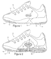
- Figure 1 is a lateral side elevational view of an article of footwear incorporating an exemplar first fluid system with aspects of the invention.
- Figure 2 is a partial cut-away view of the footwear depicting the first fluid system.
- Figure 3 is a perspective view of the first fluid system.
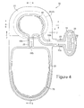
- Figure 4 is a top plan view of the first fluid system.
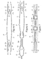
- Figure 5 is a first cross-sectional view of the first fluid system, as defined by section line 5-5 in Figure 4 .
- Figure 6 is a second cross-sectional view of the first fluid system, as defined by section line 6-6 in Figure 4 .
- Figure 7 is a third cross-sectional view of the first fluid system, as defined by section line 7-7 in Figure 4 .
- Figure 8 is an exploded perspective view of the first fluid system.
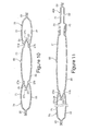
- Figure 9 is a top plan view of an exemplar second fluid system incorporating aspects of the invention.
- Figure 10 is a first cross-sectional view of the second fluid system, as defined by section line 10-10 in Figure 9 .
- Figure 11 is a second cross-sectional view of the second fluid system, as defined by section line 11-11 in Figure 9 .
- Figure 12 is a top plan view of a variation of the second fluid system.
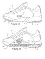
- Figure 13 is a lateral side elevational view of an article of footwear incorporating an exemplar third fluid system incorporating aspects of the invention.
- Figure 14 is a partial cut-away view of the footwear depicting the third fluid system.
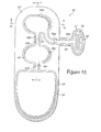
- Figure 15 is a top plan view of the third fluid system.
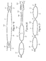
- Figure 16 is a first cross-sectional view of the third fluid system, as defined by section line 16-16 in Figure 15 .
- Figure 17 is a second cross-sectional view of the third fluid system, as defined by section line 17-17 in Figure 15 .
- Figure 18 is a top plan view of an exemplar fourth fluid system incorporating aspects of the invention.
- Figure 19 is a first cross-sectional view of the fourth fluid system, as defined by section line 19-19 in Figure 18 .
- Figure 20 is a second cross-sectional view of the fourth fluid system, as defined by section line 20-20 in Figure 18 .
- Figure 21 is a third cross-sectional view of the fourth fluid system, as defined by section line 21-21 in Figure 18 .
- Figure 22A is a perspective view of a valve suitable for use in the fluid system.
- Figure 22B is a first cross-sectional view of the valve, as defined by section line 22B-22B in Figure 22A .
- Figure 22C is a second cross-sectional view of the valve, as defined by section line 22C-22C in Figure 22A .
- Figure 22D is a third cross-sectional view of the valve, as defined by section line 22D-22D in Figure 22A .
- Figure 22E is a fourth cross-sectional view of the valve, as defined by section line 22E-22E in Figure 22A .
- Figure 22F is a fifth cross-sectional view of the valve, as defined by section line 22F-22F in Figure 22A .
- Figure 22G is an enlarged view of a weld bead depicted in Figure 22D .
- fluid systems in accordance with aspects of the present invention.
- Concepts related to the fluid systems are disclosed with reference to an article of athletic footwear having a configuration suitable for the sport of running.
- the fluid systems are not solely limited to footwear designed for running, however, and may be incorporated into a wide range of athletic footwear styles, including basketball shoes, cross-training shoes, walking shoes, tennis shoes, soccer shoes, and hiking boots, for example.
- the fluid systems may be incorporated into footwear that is generally considered to be non-athletic, including dress shoes, loafers, sandals, and work boots.
- An article of footwear 10 is depicted in Figure 1 and includes an upper 11 and a sole structure 12.
- Upper 11 has a substantially conventional configuration formed of a plurality elements, such as textiles, foam, and leather materials, that are stitched or adhesively bonded together to form an interior void for securely and comfortably receiving a foot.
- Sole structure 12 is positioned below upper 11 and includes two primary elements, a midsole 13 and an outsole 14.
- Midsole 13 is secured to a lower surface of upper 11, through stitching or adhesive bonding, for example, and operates to attenuate ground reaction forces as sole structure 12 contacts the ground, as during walking or running.
- Outsole 14 is secured to a lower surface of midsole 13 and is formed of a durable, wear-resistant material that engages the ground.
- sole structure 12 may include an insole 15, which is located within the void in upper 11 and adjacent to the foot to enhance the comfort of article of footwear 10.
- Midsole 13 is primarily formed of a polymer foam material, such as polyurethane or ethylvinylacetate, that at least partially encapsulates a fluid system 20.
- fluid system 20 is primarily positioned in a heel region and a midfoot region of midsole 13, but may be positioned in any region of midsole 13 to impart a desired degree of force attenuation or stability, for example.
- midsole 13 may incorporate multiple fluid systems 20, with a first fluid system 20 being positioned in the heel region and a second fluid system 20 being positioned in a forefoot region of midsole 13, for example.
- Fluid system 20 may also have a configuration that extends from the heel region to the forefoot region of midsole 13, thereby extending through a substantial portion of midsole 13.
- Fluid system 20 is depicted individually in Figures 3-8 and provides a structure that utilizes ambient air to impart additional force attenuation, for example, as sole structure 12 contacts the ground.
- fluid system 20 may impart stability, improve responsiveness, and enhance the ride characteristics of midsole 13.
- the primary elements of fluid system 20 are a filter assembly 30, a pair of conduits 40a and 40b, a pair of valves 50a and 50b that are positioned within conduits 40a and 40b, respectively, a pump chamber 60, and a pressure chamber 70.
- a fluid such as ambient air
- the fluid then passes through valve 50a and into pump chamber 60.
- the fluid As pump chamber 60 is compressed, the fluid enters conduit 40b and passes through valve 50b to enter pressure chamber 70.
- a combination of the fluid within pump chamber 60 and pressure chamber 70 imparts the ground reaction force attenuation, for example, that is provided by fluid system 20. In some embodiments, however, a majority of the ground reaction force attenuation provided by fluid system 20 may be imparted by pressure chamber 70.
- a pair of polymer layers 21 and 22 are bonded together at specific bonding locations 23 to define portions of filter assembly 30, conduits 40a and 40b, and pressure chamber 70. That is, filter assembly 30, conduits 40a and 40b, and pressure chamber 70 are formed between unbonded positions of layers 21 and 22.
- Pump chamber 60 is also formed between unbonded positions of layers 21 and 22. As will be described in greater detail below, however, a portion of pump chamber 60 is also formed from a pair of layers 24 and 25.
- the position of conduit 40a with respect to layers 21 and 22 is selected to provide a fluid path that extends between a fluid source, such as ambient air, and pump chamber 60, thereby permitting the fluid to flow from filter assembly 30 to pump chamber 60.
- conduit 40b is selected to provide a fluid path that extends between pump chamber 60 and pressure chamber 70, which permits the fluid to also flow from pump chamber 60 to pressure chamber 70. In this configuration, therefore, the fluid may flow between layers 21 and 22 to pass through conduits 40a and 40b.
- barrier materials are suitable for layers 21 and 22, including barrier materials that are substantially impermeable to the fluid within fluid system 20.
- barrier materials may include, for example, alternating layers of thermoplastic polyurethane and ethylene-vinyl alcohol copolymer, as disclosed in U.S. Patent Numbers 5,713,141 and 5,952,065 to Mitchell et al .
- a variation upon this material wherein the center layer is formed of ethylene-vinyl alcohol copolymer, the two layers adjacent to the center layer are formed of thermoplastic polyurethane, and the outer layers are formed of a regrind material of thermoplastic polyurethane and ethylene-vinyl alcohol copolymer may also be utilized.
- Another suitable material is a flexible microlayer material that includes alternating layers of a gas barrier material and an elastomeric material, as disclosed in U.S. Patent Numbers 6,082,025 and 6,127,026 to Bonk et al .
- fluid system 20 operates to draw fluid, such as air, into pump chamber 60 and pressure chamber 70 in order to provide ground reaction force attenuation to article of footwear 10. If a portion of the fluid within pump chamber 60 or pressure chamber 70 should escape from fluid system 20 by diffusing or otherwise passing through polymer layers 21 and 22, then fluid system 20 will operate to draw additional fluid into pump chamber 60 and pressure chamber 70, thereby replenishing the escaped fluid.
- fluid system 20 operates to draw fluid, such as air, into pump chamber 60 and pressure chamber 70 in order to provide ground reaction force attenuation to article of footwear 10. If a portion of the fluid within pump chamber 60 or pressure chamber 70 should escape from fluid system 20 by diffusing or otherwise passing through polymer layers 21 and 22, then fluid system 20 will operate to draw additional fluid into pump chamber 60 and pressure chamber 70, thereby replenishing the escaped fluid.
- polymer layers 21 and 22 need not provide a barrier that is substantially impermeable to the fluid within fluid system 20, but may be at least partially impermeable to the fluid within fluid system 20.
- Suitable polymer materials include, therefore, thermoplastic elastomers such as polyurethane, polyester, polyester polyurethane, and polyether polyurethane.
- thermoplastic elastomers such as polyurethane, polyester, polyester polyurethane, and polyether polyurethane.
- the specific material forming layers 21 and 22 may be selected based primarily upon the engineering properties of the material, rather than the barrier properties of the material. Accordingly, the material forming layers 21 and 22 may be selected to exhibit a specific tensile strength, elastic modulus, durability, degree of light transmission, elasticity, resistance to corrosion or chemical breakdown, or abrasion resistance, for example.
- Filter assembly 30 has the general structure of a filter assembly described in U.S. Patent Application Serial Number 09/887,523, which was filed June 21, 2001 and is hereby entirely incorporated by reference.
- Filter assembly 30 is generally positioned on an exterior of article of footwear 10 and includes two primary components, a cover element 31 and a filter material 32.
- Cover element 31 extends over filter material 32 and includes a plurality of perforations that permit air to access filter material 32, while preventing relatively large objects, such as stones and tree branches, from directly contacting and potentially damaging filter material 32.
- the fluid is drawn into fluid system 20 through filter material 32, which limits water, other liquids, and a variety of particulates from hindering the operation of various system components, such as valves 50a and 50b and pressure chamber 70.
- valves 50a and 50b are one-directional valves that permit fluid to flow in a first direction, but limit or check fluid flow in an opposite second direction. Particulates that collect around and within valves 50a and 50b may affect the one-directional operation of valves 50a and 50b, thereby permitting the fluid to flow through fluid system 20 in an unintended manner. In the absence of filter assembly 30, water and particulates could also collect within pressure chamber 70. In some embodiments, a portion of pressure chamber 70 may be visible through apertures formed in the polymer foam material of midsole 13.
- Particulates that collect within pressure chamber 70 could become visible from the exterior of article of footwear 10, thereby decreasing the aesthetic properties of article of footwear 10. If water were also permitted to enter and collect in pump chamber 60, pressure chamber 70, or other portions of fluid system 20, the weight of article of footwear 10 may increase significantly. Furthermore, particulates may act as an abrasive that wears away portions of fluid system 20, thereby decreasing durability. Accordingly, filter assembly 30 acts to limit the entry of liquids and particulates that may have a detrimental effect upon fluid system 20.
- filter material 32 is polytetrafluoroethylene (PTFE), which may be deposited on a substrate material. PTFE exhibits the required characteristics and is suitably durable when attached to a substrate such as non-woven polyester. A variation upon the standard formulation of PTFE is expanded polytetrafluoroethylene (ePTFE) which is manufactured by, for example, W.L. Gore & Associates.
- ePTFE expanded polytetrafluoroethylene
- other suitable materials for filter material 32 include high density polyethylene, ultrahigh molecular weight polyethylene, polyvinylidene fluoride, polypropylene, and certain ceramic filter materials. Knit materials, woven materials, nonwoven materials, laminate structures consisting of one or more differing filter materials, and paper may also be suitable.
- filter material 32 may be formed of a solid, porous material.
- Valves 50a and 50b may be any type of valve that performs in accordance with the design requirements of system 20.
- Valves structures that may be utilized for valves 50a and 50b include, for example, duckbill valves manufactured by Vernay Laboratories, Inc. and the two-layer polymer valves disclosed in U.S. Patent Numbers 5,144,708 to Pekar and 5,564,143 to Pekar et al . Both types of valves are generally considered one-directional valves that permit fluid flow in a first direction, but limit fluid flow in an opposite second direction. With respect to fluid system 20, valve 50a permits fluid flow in the direction from filter assembly 30 to pump chamber 60, and valve 50b permits fluid flow in the direction from pump chamber 60 to pressure chamber 70.
- Valves 50a and 50b limit fluid flow in opposite directions. Depending upon the specific characteristics that a fluid system is intended to impart, valves that permit fluid flow in both directions may also be utilized within the scope of the present invention. In addition to the valve structures disclosed above, valves 50a and 50b may also have the configuration of a valve 100, which is described with reference to Figures 22A-22G following a more detailed discussion regarding the operation of fluid system 20.
- Fluid system 20 is configured to provide an air inlet that is separate from pump chamber 60.
- fluid system 20 is depicted as having an air inlet at filter assembly 30, and conduit 40a extends between filter assembly 30 and pump chamber 60. Accordingly, air is introduced into fluid system 20 through an air inlet that is separate from pump chamber 60.
- the separate air inlet and pump chamber 60 permits the air inlet to be located on any portion of footwear 10, including upper 11, and this configuration permits the air inlet to include a filter material 32 that is not positioned in an area of repetitive compressive forces.
- fluid system 20 Another feature of fluid system 20 is the direct fluid communication between pump chamber 60 and pressure chamber 70.
- Conduit 40b leads directly from pump chamber 60 to pressure chamber 70 and provides an area for positioning valve 50b. Accordingly, a minimum number of fluid system components are placed in the fluid path between pump chamber 60 and pressure chamber 70. This configuration reduces the pressure losses that arise through transfer of the fluid from pump chamber 60 to pressure chamber 70. Furthermore, this configuration provides a fluid system with a relatively small number of components.
- fluid system 20 The pressure of the fluid within the various components of fluid system 20 changes depending upon the manner in which article of footwear 10 is utilized, the frequency at which sole structure 12 is compressed, and the force that compresses sole structure 12, for example.
- the operation of fluid system 20, and the pressure of the fluid within the various components of fluid system 20 will be discussed with regard to an initial state, a transition state, and an equilibrium state.
- pump chamber 60 and pressure chamber 70 contain a fluid with an initial pressure that is substantially equal to the ambient pressure of air that surrounds article of footwear 10 and fluid system 20.
- the pressure within pressure chamber 70 increases from the initial pressure to an equilibrium pressure, at which time fluid system 20 is in the equilibrium state.
- Fluid system 20 is at least partially encapsulated within the polymer foam material of midsole 13.
- fluid system 20 may be positioned within a mold having the shape of midsole 13.
- fluid system 20 is either in the initial state or the pressure of the fluid within pump chamber 60 and pressure chamber 70 is slightly elevated above the ambient pressure. Accordingly, pump chamber 60 and pressure chamber 70 are in an expanded configuration rather than a collapsed configuration. That is, the fluid places sufficient outward pressure upon layers 21 and 22 to prevent pump chamber 60 and pressure chamber 70 from significantly collapsing.
- the polymer foam material of midsole 13 is then injected into the mold and around fluid system 20.
- fluid system 20 Upon curing of the polymer foam material, fluid system 20 is securely encapsulated within midsole 13 such that pump chamber 60 and pressure chamber 70 remain in the expanded configuration. Furthermore, the polymer foam material may bond to the exterior surfaces of layers 21 and 22. Midsole 13 is then secured to upper 11 and outsole 14 to form article of footwear 10.
- the pressure of the fluid within pump chamber 60 and pressure chamber 70 may be slightly elevated above the ambient pressure, as discussed above.
- the fluid within fluid system 20 may diffuse through layers 21 and 22 or otherwise escape from fluid system 20 until the pressure of the fluid is substantially equal to the ambient pressure of air that surrounds article of footwear 10 and fluid system 20. Accordingly, when an individual first places article of footwear 10 upon the foot, fluid system 20 is in the initial state.
- Fluid system 20 may be positioned in the heel region of midsole 13, as depicted in Figure 2 . More particularly, fluid system 20 may be positioned such that pressure chamber 70 is positioned directly below the calcaneus bone of the individual wearing article of footwear 10, and pump chamber 60 is positioned forward of pressure chamber 70.
- sole structure 12 is compressed against the ground, which compresses both midsole 13 and fluid system 20.
- pressure chamber 70 bears a large portion of the force that causes the compression. As the foot rolls forward, however, the pressure upon pump chamber 60 increases. The compression of pump chamber 60 causes the pressure of the fluid within pump chamber 60 to increase.
- Valves 50a and 50b are one-directional valves that permit fluid flow in a first direction, but limit or check fluid flow in an opposite second direction.
- Valve 50a permits fluid to flow from filter assembly 30 to pump chamber 60, but limits fluid flow in the opposite direction. When pump chamber 60 is compressed, therefore, valve 50a effectively prevents the fluid from flowing to filter assembly 30.
- Valve 50b permits fluid to flow from pump chamber 60 to pressure chamber 70 when the pressure differential between pump chamber 60 and pressure chamber 70 exceeds the pressure losses discussed above.
- midsole 13 As the first step of the individual progresses, and the foot no longer places a significant force upon midsole 13, the compressive force exerted upon fluid system 20 decreases and midsole 13 returns to an uncompressed configuration.
- the pressure of the fluid within pressure chamber 70 remains elevated and fluid system 20 remains in the transition state. Due to the bonds between the polymer material of midsole 13 and layers 21 and 22, midsole 13 will place an outward force on pump chamber 60 as midsole 13 returns to the uncompressed configuration. That is, the polymer material of midsole 13 may attempt to expand the compressed pump chamber 60. This action causes the pressure within pump chamber 60 to become negative relative to the ambient pressure of the air outside of article of footwear 10 and fluid system 20. Accordingly, a negative pressure differential is formed between pump chamber 60 and the ambient air.
- Filter assembly 30 and conduit 40a form a fluid path between the ambient air and pump chamber 60.
- ambient air will pass through filter assembly 30, enter conduit 40a, pass through valve 50a, and enter pump chamber 60, thereby placing additional fluid within pump chamber 60.
- air will flow into pump chamber 60 as midsole 13 expands from being compressed.
- the various pressure losses mentioned above may be associated with resistance from filter material 32, friction that occurs as the fluid passes through conduit 40a, and an opening pressure of valve 50a.
- pump chamber 60 and pressure chamber 70 were substantially equal to the ambient pressure of air. As midsole 13 was compressed, therefore, pump chamber 60 and pressure chamber 70 provided a relatively small degree of support. That is, the pressure of the fluid within pump chamber 60 and pressure chamber 70 was not sufficient to provide a relatively large degree of ground reaction force attenuation. As the individual continues to take steps and the pressure of the fluid within pressure chamber 70 increases, however, the degree of support and ground reaction force attenuation provided by pressure chamber 70 also increases. After a sufficient number of steps, the pressure within pressure chamber 70 becomes substantially equal to the pressure of pump chamber 60 when compressed by the foot. When this occurs, the pressure differential between pump chamber 60 and pressure chamber 70 becomes insufficient to induce further fluid transfer between pump chamber 60 and pressure chamber 70. Accordingly, the pressure of the fluid within pressure chamber 70 will eventually balance the compression of pump chamber 60, and fluid system 20 will reach the equilibrium state.
- the volume of fluid that is transferred from pump chamber 60 to pressure chamber 70 during each step of the individual is at least partially dependent upon the volume of pump chamber 60. More particularly, an increase in the volume of pump chamber 60 will generally result in a greater volume of fluid entering pressure chamber 70, thereby decreasing the total time in which fluid system 20 remains in the transition stage.
- One manner of increasing the volume of pump chamber 60 involves increasing the width and length of pump chamber 60. Although this may be an effective manner of increasing the volume of pump chamber 60, the area of midsole 13 is limited and other components of fluid system 20 (i.e., conduits 40a and 40b, and pressure chamber 60) must fit within this area.
- Another manner of increasing the volume of pump chamber 60 involves increasing the vertical thickness (i.e., distance between layers 21 and 22) of pump chamber 60.
- Fluid system 20 may be formed through a process that involves heating layers 21 and 22 and utilizing a mold to bond layers 21 and 22 together at bonding locations 23.
- increasing the vertical thickness of pump chamber 60 may involve stretching layers 21 and 22 while located within the mold.
- a thickness of layers 21 and 22 decreases, which may decrease the durability of pump chamber 60 or increase the degree to which fluid diffuses through layers 21 and 22 at pump chamber 60.
- layers 24 and 25 are utilized to form at least a portion of pump chamber 60.
- Layers 24 and 25 extend at least partially around pump chamber 60 and form at least a portion of a sidewall of pump chamber 60. Each of layers 24 and 25 define an aperture 26, as depicted in Figure 8 .
- layer 24 is bonded to layer 21 at a first bonding location 27a
- layer 25 is bonded to layer 22 at a second bonding location 27b
- layers 24 and 25 are bonded to each other at a third bonding location 27c that is adjacent to the edges that define apertures 26. More particularly, bonding locations 27a and 27b are depicted as being aligned through the thickness of pump chamber 20, and bonding location 27c is depicted as being located adjacent aperture 26 and in a position that is offset from bonding locations 27a and 27b.
- this configuration forms a zigzag or W-shaped structure in the sidewalls of pump chamber 60.
- the bonds formed at bonding locations 27a-27c may exhibit different configurations.
- bonding location 27c may be spaced inward from the edges that defines apertures 26.
- bonding locations 27a and 27b may be adjacent to or spaced inward from an outer edge of layers 24 and 25.
- the zigzag or W-shaped structure in the sidewalls of pump chamber 60 facilitates expansion of pump chamber 60. That is, the vertical thickness of pump chamber 60 may increase substantially over a configuration wherein layers 21 and 22 are bonded to each other.
- this structure for the sidewalls of pump chamber 60 imparts a self-expanding feature. That is, pump chamber 60 may expand and inflate with fluid without other expansion structures.
- expansion of the polymer material of midsole 13 may attempt to expand the compressed pump chamber 60.
- the polymer material of midsole 13 may be insufficient to expand pump chamber 60 and draw fluid into pump chamber 60.
- the presence of layers 24 and 25, however, imparts a configuration wherein expansion will occur independent of the presence of the polymer material of midsole 13.
- the presence of layers 24 and 25 decouples the polymer material of midsole 13 from the expansion of pump chamber 60 so that fluid system 20 may be utilized in an environment where no external polymer foam is present.
- Fluid system 20 is depicted as generally extending along a horizontal plane. Prior to bonding, each of layers 21, 22, 24, and 25 will also extend along the horizontal plane. The formation of bonds at bonding locations 27a-27c induces an incline in layers 24 and 25 that effectively holds layers 21 and 22 away from each other in the absence of outside forces. That is, the incline in layers 24 and 25 provide the self-expanding feature inherent in pump chamber 20.
- fluid system 20 may be formed through a process that involves heating layers 21 and 22 and utilizing a mold to bond layers 21 and 22 together at bonding locations 23.
- layers 24 and 25 are also bonded to form the various bonding locations 27a, 27b, and 27c.
- Fluid system 20 may be formed, therefore, through a thermoforming process that involves heating layers 21, 22, 24, and 25 and utilizing a mold to bond layers 21, 22, 24, and 25 together in the desired locations.
- layers 24 and 25 may be placed between portions of layers 21 and 22 that will become pump chamber 60, and valves 50a and 50b may be placed between portions of layers 21 and 22 that will become conduits 40a and 40b.
- filter material 32 may be placed between portions of layers 21 and 22 that will become filter assembly 30.
- the mold utilized in the thermoforming process may have areas that compress layers 21 and 22 to form bonding locations 23. Furthermore, the mold may have cavities configured to receive portions of layers 21 and 22 and define the shapes of conduits 40a and 40b, pump chamber 60, and pressure chamber 70.
- a fluid may be injected between layers 21 and 22 to press layers 21 and 22 into the various contours of the mold.
- a vacuum may be induced on the exterior of layers 21 and 22 to also draw layers 21 and 22 into the various contours of the mold.
- Bonding locations 23 are areas of fluid system 20 wherein layers 21 and 22 are bonded to each other. Accordingly, fluid system 20 is effectively formed of two polymer layers at bonding locations 23 and these two polymer layers are bonded through the entire thickness of fluid system 20 at bonding locations 23. In areas of fluid system 20 where layers 24 and 25 are present, bonding occurs between specified layers, but not through the entire thickness of fluid system 20. For example, bonds form at bonding locations 27a and 27b, but not between layers 24 and 25 at these particular locations. In addition, a bond forms at bonding location 27c, but not between layers 21 and 24 and layers 22 and 25 at this particular location. In order to inhibit bonds from forming between specified areas of layers 21, 22, 24, and 25, a blocking material may be utilized.
- Blocking materials when located between two polymer layers, provide an effective means by which bonding is inhibited. Accordingly, a blocking material may be applied or positioned adjacent to various surfaces of layers 21, 22, 24, and 25 where bonding would otherwise occur, but not to portions of layers 21, 22, 24, and 25 where bonding is intended to occur. Suitable blocking materials include layers or coatings that incorporate polytetrafluoroethylene, silicone, or mylar, for example.
- the various positions where a blocking material may be applied to inhibit bonding are shown by locations 28.
- the blocking material may be applied between layers 24 and 25 in an area that corresponds with bonding locations 27a and 27b.
- the blocking material may be applied to each of the unbonded surfaces of layers 24 and 25, or the blocking material may be applied to only one of the unbonded surfaces of layers 24 and 25.
- the blocking material may be a separate sheet of material that extends between the unbonded surfaces of layers 24 and 25.
- the blocking material may also be applied between layers 21 and 24 and layers 22 and 25 in areas that correspond with bonding location 27c.
- fluid system 20 may be formed from flat thermoplastic sheets that are bonded together to define conduits 40a and 40b, portions of pump chamber 60, and pressure chamber 70.
- layers 21 and 22 may be separately formed to include indentations corresponding with conduits 40a and 40b, portions of pump chamber 60, and pressure chamber 70.
- Layers 24 and 25 may then be placed between layers 21 and 22, and bonds may be formed to define bonding locations 27a, 27b, and 27c.
- fluid system 20 or individual components of fluid system 20 may be manufactured through blow molding or rotational molding processes. In situations where individual components of fluid system 20 are formed separately, the individual components may be subsequently joined together to form fluid system 20. That is, a bonding technique may be utilized to join conduits 40a and 40b, pump chamber 60, and pressure chamber 70, as described in U.S. Patent Application Serial Number 10/351,876, which was filed January 27, 2003 and is hereby entirely incorporated by reference.
- pump chamber 60 is effectively formed from four layers 21, 22, 24, and 25.
- one or more additional layers that are similar to layers 24 and 25 may be utilized.
- breaks or gaps in bonding location 27c may be formed between layers 24 and 25 to permit fluid flow into and out of pump chamber 60. Accordingly, a blocking material may also be utilized in these areas to inhibit bonding.
- fluid system 20 may be modified significantly to accommodate various applications.
- the lengths of conduits 40a and 40b may be modified such that pump chamber 60 may be positioned in the forefoot region of footwear 10 while pressure chamber 70 remains in the heel region.
- pressure chamber 70 may be positioned in the forefoot region.
- the relative volumes and shapes of pump chamber 60 and pressure chamber 70 may also vary significantly.
- fluid system 20 is configured so that pump chamber 60 is separated from pressure chamber 70. With reference to Figures 9-11 , however, pressure chamber 70 extends around the side portion of pump chamber 60.
- the pressure of the fluid within pressure chamber 70 at the equilibrium state is at least partially a function of the degree to which pressure chamber 70 extends around the side portion of pump chamber 60.
- the maximum pressure of pressure chamber 70 is approximately equal to the maximum pressure that the individual may induce within pump chamber 60.
- the increase in pressure of the fluid within pressure chamber 70 provides support against compressing pump chamber 60.
- the degree to which pressure chamber 70 extends around pump chamber 60 increases, the amount of support that pressure chamber 70 may provide to resist compressions of pump chamber 60 also increases.
- pressure chamber 70 extends only partially around the side portion of pump chamber 60, then portions of pump chamber 60 that are not adjacent to pressure chamber 70 may remain compressible. If, however, pressure chamber 70 extends entirely around pump chamber 60, then pressure chamber 70 may substantially limit the amount that pump chamber 60 may be compressed. Accordingly, the pressure of the fluid within pressure chamber 70 is at least partially determined by the degree to which pressure chamber 70 extends around the side portion of pump chamber 60. The pressure of the fluid within pressure chamber 70 is, therefore, effectively limited by extending pressure chamber 70 around at least a portion of pump chamber 60. Accordingly, the degree to which pressure chamber 70 extends around the side portion of pump chamber 60 contributes to a pressure-limiting feature of fluid system 20. Other factors that determine the pressure of the fluid within pressure chamber 70 include the relative forces exerted upon pump chamber 60 and pressure chamber 70, the relative dimensions of pump chamber 60 and pressure chamber 70, and the compressibility of the foam material encapsulating fluid system 20, for example.
- Pressure chamber 70 forms a generally C-shaped structure with an interior area that accommodates pump chamber 60.
- pressure chamber 70 may extend around the side portion of pump chamber 60 to a lesser or greater degree.
- pressure chamber 70 extends at least partially around pump chamber 60, the sidewalls of pump chamber 60 may still be formed to exhibit the expandable configuration discussed above. That is, layers 24 and 25 may be positioned between layers 21 and 22 to impart an expandable configuration to pump chamber 60. Layers 24 and 25 also form a divider between pump chamber 60 and pressure chamber 70 that segregates the fluid within pump chamber 60 from the fluid within pressure chamber 70.
- layers 24 and 25 imparted an expandable configuration to a portion of the sidewalls of pump chamber 60.
- layers 24 and 25 impart an expandable configuration to a portion of the sidewalls of each of pump chamber 60 and pressure chamber 70.
- the vertical thickness of pressure chamber 70 increases as fluid is pumped into pressure chamber 70, the vertical thickness of pump chamber 60 increases in a corresponding manner. Accordingly, the vertical thickness of pump chamber 60 is coupled to the vertical thickness of pressure chamber 70 in configurations where layers 24 and 25 form portions of both pump chamber 60 and pressure chamber 70.
- Bonding locations 23 are areas of fluid system 20 wherein layers 21 and 22 are bonded to each other, and bonding locations 23 define the various components of fluid system 20, including pump chamber 60 and pressure chamber 70.
- the portion of bonding locations 23 between pump chamber 60 and pressure chamber 70 has a wave-like configuration that may also assist with ensuring that pump chamber 60 remains expanded to increase the vertical thickness of pump chamber 60. That is, the combination of the wave-like configuration of bonding locations 23 and layers 24 and 25 imparts an expandable configuration to a portion of the sidewalls of each of pump chamber 60 and pressure chamber 70.
- aspects of the invention involve a fluid system having a pump chamber and a pressure chamber that are in fluid communication.
- the pump chamber includes a first pair of layers and a second pair of layers.
- the first pair of layers form opposite surfaces of the pump chamber, and the second pair of layers are positioned between the first pair of layers and extend at least partially around the pump chamber.
- the layers are secured to each other to form a zigzag-shaped or W-shaped structure in the pump chamber. Additional aspects of the invention involve other structures or configurations that form an expandable pump chamber.
- FIG. 13 An article of footwear 10' is depicted in Figure 13 and includes an upper 11' and a sole structure 12'.
- Upper 11' has a substantially conventional configuration formed of a plurality elements, such as textiles, foam, and leather materials, that are stitched or adhesively bonded together to form an interior void for securely and comfortably receiving a foot.
- Sole structure 12' is positioned below upper 11' and includes two primary elements, a midsole 13' and an outsole 14'.
- Midsole 13' is secured to a lower surface of upper 11', through stitching or adhesive bonding, for example, and operates to attenuate ground reaction forces as sole structure 12' contacts the ground, as during walking or running.
- Outsole 14' is secured to a lower surface of midsole 13' and is formed of a durable, wear-resistant material that engages the ground.
- sole structure 12' may include an insole 15', which located within the void in upper 11' and adjacent to the foot to enhance the comfort of article of footwear 10'.
- Midsole 13' is primarily formed of a polymer foam material, such as polyurethane or ethylvinylacetate, that at least partially encapsulates a fluid system 20'.
- fluid system 20' is positioned in both of a heel region and a forefoot region of midsole 13, but may be limited to one region of midsole 13 to impart a desired degree of force attenuation or stability, for example.
- midsole 13' may incorporate multiple fluid systems 20', with a first fluid system 20' being positioned in the heel region and a second fluid system 20' being positioned in the forefoot region, for example.
- Fluid system 20' is depicted individually in Figures 15 and 16 and provides a structure that utilizes ambient air to impart additional force attenuation, for example, as sole structure 12' contacts the ground.
- fluid system 20' may impart stability, improve responsiveness, and enhance the ride characteristics of midsole 13'.
- the primary elements of fluid system 20' are a filter assembly 30', a three conduits 40a'-40c', three valves 50a'-50c' that are positioned within conduits 40a'-40c', respectively, a pair of pump chambers 60a' and 60b', and a pressure chamber 70'.
- a fluid such as ambient air
- the fluid then passes through valve 50a' and into pump chamber 60a'.
- pump chamber 60a' As pump chamber 60a' is compressed, the fluid enters conduit 40b' and passes through valve 50b' to enter pump chamber 60b'. As pump chamber 60b' is compressed, the fluid enters conduit 40c' and passes through valve 50c' to enter pressure chamber 70'.
- a combination of the fluid within pump chamber 60a', pump chamber 60b', and pressure chamber 70' imparts the ground reaction force attenuation, for example, that is provided by fluid system 20'. In some embodiments, however, a majority of the ground reaction force attenuation provided by fluid system 20' may be imparted by pressure chamber 70'.
- a pair of polymer layers 21' and 22' are bonded together at specific bonding locations 23' to define portions of filter assembly 30', conduits 40a'-40c', pump chambers 60a' and 60b', and pressure chamber 70'. That is, filter assembly 30', conduits 40a'-40c', pump chambers 60a' and 60b', and pressure chamber 70' are formed between unbonded positions of layers 21' and 22'.
- the position of conduit 40a with respect to layers 21' and 22' is selected to provide a fluid path that extends between a fluid source, such as ambient air, and pump chamber 60a', thereby permitting the fluid to flow from filter assembly 30' to pump chamber 60a'.
- Conduit 40b' is positioned to extend between pump chambers 60a' and 60b'
- conduit 40c' is positioned to extend between pump chamber 60b' and pressure chamber 70'.
- Filter assembly 30' which includes a cover element 31' and a filter material 32', may also have the general configuration of filter assembly 30.
- valves 50a', 50b', and 50c' may have the general configuration of valves 50a and 50b, and may also have the configuration of valve 100, which is described below with reference to Figures 22A-22G . Accordingly, many of the components of fluid system 20' may be analogous in structure and materials to the various components discussed above for fluid system 20.
- fluid system 20' The pressure of the fluid within the various components of fluid system 20' changes depending upon the manner in which article of footwear 10' is utilized, the frequency at which sole structure 12' is compressed, and the force that compresses sole structure 12', for example.
- the operation of fluid system 20', and the pressure of the fluid within the various components of fluid system 20' will be discussed with regard to an initial state, a transition state, and an equilibrium state.
- pump chambers 60a' and 60b' and pressure chamber 70' contain a fluid with an initial pressure that is substantially equal to the ambient pressure of air that surrounds article of footwear 10' and fluid system 20'.
- the pressure within pressure chamber 70' increases from the initial pressure to an equilibrium pressure, at which time fluid system 20' is in the equilibrium state.
- Fluid system 20' may be positioned in midsole 13' so as to extend through the heel region and the forefoot region of footwear 10', as depicted in Figure 14 . More particularly, fluid system 20' may be positioned such that pressure chamber 70' is positioned directly below the calcaneus bone of the individual wearing article of footwear 10', and each of pump chambers 60a' and 60b' are positioned forward of pressure chamber 70'.
- sole structure 12' is compressed against the ground, which compresses both midsole 13' and fluid system 20'.
- pressure chamber 70' bears a large portion of the force that causes the compression.
- pump chamber 60a' passes through conduit 40b' and valve 50b' and into pump chamber 60b'.
- fluid system 20' is placed in the transition state due to increases in pressure of both of pump chambers 60a' and 60b' and pressure chamber 70'.
- Valves 50a-50c' are one-directional valves that permit fluid flow in a first direction, but limit or check fluid flow in an opposite second direction.
- Valve 50a' permits fluid to flow from filter assembly 30' to pump chamber 60a', but limits fluid flow in the opposite direction. When pump chamber 60a' is compressed, therefore, valve 50a' effectively prevents the fluid from flowing to filter assembly 30'.
- Valve 50b' permits fluid to flow from pump chamber 60a' to pump chamber 60b' when the pressure differential between pump chamber 60a' and pump chamber 60b' exceeds the pressure losses discussed above.
- valve 50c' permits fluid to flow from pump chamber 60b' to pressure chamber 70', while inhibiting fluid flow in the opposite direction.
- midsole 13' As the first step of the individual progresses, and the foot no longer places a significant force upon midsole 13', the compressive force exerted upon fluid system 20' decreases and midsole 13' returns to an uncompressed configuration.
- the pressure of the fluid within pressure chamber 70' remains elevated and fluid system 20' remains in the transition state. Due to the bonds between the polymer material of midsole 13' and layers 21' and 22', midsole 13' will place an outward force on pump chamber 60a' as midsole 13' returns to the uncompressed configuration. That is, the polymer material of midsole 13' may attempt to expand the compressed pump chamber 60a'. This action causes the pressure within pump chamber 60a' to become negative relative to the ambient pressure of the air outside of article of footwear 10' and fluid system 20'.
- a negative pressure differential is formed between pump chamber 60a' and the ambient air.
- Filter assembly 30' and conduit 40a' form a fluid path between the ambient air and pump chamber 60a'.
- the negative pressure differential exceeds various pressure losses associated with fluid system 20', ambient air will pass through filter assembly 30', enter conduit 40a', pass through valve 50a', and enter pump chamber 60', thereby placing additional fluid within pump chamber 60a'.
- air will flow into pump chamber 60a' as midsole 13' expands from being compressed.
- the various pressure losses mentioned above may be associated with resistance from filter material 32', friction that occurs as the fluid passes through conduit 40a', and an opening pressure of valve 50a'.
- pump chambers 60a' and 60b' and pressure chamber 70' were substantially equal to the ambient pressure of air.
- pump chambers 60a' and 60b' and pressure chamber 70' provided a relatively small degree of support. That is, the pressure of the fluid within pump chambers 60a' and 60b' and pressure chamber 70' was not sufficient to provide a relatively large degree of ground reaction force attenuation.
- the degree of support and ground reaction force attenuation provided by pressure chamber 70' also increases. After a sufficient number of steps, the pressure within pressure chamber 70' becomes substantially equal to the pressure of pump chamber 60b' when compressed by the foot.
- Fluid system 20 included a single pump chamber 60.
- fluid system 20' includes pump chamber 60a' and pump chamber 60b'.
- An advantage of incorporating both of pump chambers 60a' and 60b' in fluid system 20' relates to the resulting pressure in pressure chamber 70'. More particularly, providing two pump chambers 60a' and 60b' in fluid system 20' increases the pressure in pressure chamber 70' beyond that of pressure chamber 70 once fluid system 20' attains the equilibrium state. That is, pressure chamber 70' will generally attain a higher pressure than pressure chamber 70.
- pressure chamber 70' will generally attain a higher pressure than pressure chamber 70.
- fluid is drawn into pump chamber 60a' and has a pressure that is approximately equal to the pressure of ambient air that surrounds article of footwear 10' and fluid system 20'.
- Pa max the pressure of the fluid within pump chamber 60a' increases from ambient pressure to a higher pressure, which will be referred to as Pa max.
- Fluid is then transferred from pump chamber 60a' to pump chamber 60b'. A portion of that fluid is also transferred from pump chamber 60b' to pressure chamber 70'.
- the highest pressure that pump chamber 60b' may theoretically attain due to fluid transfer from pump chamber 60a' to pump chamber 60b' is Pa max.
- pump chamber 60b' may attain a higher pressure than Pa max when compressed. Given the pressure losses discussed above and the fact that the increased pressure of pump chamber 60b' may limit the degree to which pump chamber 60a' may be compressed, the actual highest pressure that pump chamber 60a' attains may be less than Pa max.
- pressure chamber 70' Given the pressure losses discussed above and the fact that the increased pressure of pressure chamber 70' may limit the degree to which pump chamber 60b' may be compressed, the actual highest pressure that pressure chamber 70' attains may be less than Pb max. In general, however, pressure chamber 70' will attain a higher pressure than pressure chamber 70 due to the presence of two pump chambers 60a' and 60b'.
- Fluid system 20' may be formed through a process that involves heating layers 21' and 22' and utilizing a mold to bond layers 21' and 22' together at bonding locations 23'. Fluid system 20' may be formed, therefore, through a thermoforming process that is similar to the process discussed for fluid system 20.
- a variety of other processes may be utilized to form fluid system 20'.
- layers 21' and 22' may be formed from flat thermoplastic sheets that are bonded together to define conduits 40a'-40c', pump chambers 60a' and 60b', and pressure chamber 70'.
- layers 21' and 22' may be separately formed to include indentations corresponding with elements of fluid system 20'.
- fluid system 20' or individual components of fluid system 20' may be manufactured through blow molding or rotational molding processes. In situations where individual components of fluid system 20' are formed separately, the individual components may be subsequently joined together to form fluid system 20' as described in U.S. Patent Application Serial Number 10/351,876, which was filed January 27, 2003 and is hereby entirely incorporated by reference.
- fluid system 20' may be modified significantly to accommodate various applications.
- the lengths of conduits 40a'-40c' may be modified such that pump chambers 60a' and 60b' may be positioned in the heel region of footwear 10'.
- pressure chamber 70' may be positioned in the forefoot region.
- the relative volumes and shapes of pump chambers 60a' and 60b' and pressure chamber 70' may also vary significantly.
- fluid system 20 is configured so that pump chambers 60a' and 60b' is separated from pressure chamber 70'. With reference to Figures 18-21 , however, pressure chamber 70' extends around the side portion of pump chamber 60b'.
- Pressure chamber 70' forms a generally C-shaped structure with an interior area that accommodates pump chamber 60b'. In other embodiments of fluid system 20', however, pressure chamber 70' may extend around the side portion of pump chamber 60b' to a lesser or greater degree, or pressure chamber 70' may extend partially around pump chamber 60a'. In some aspects of the invention, portions of pressure chamber 70' may extend around both of pump chambers 60a' and 60b'.
- Pump chamber 60a' exhibits an expandable configuration that is similar to pump chamber 60. That is, a pair of layers 24' and 25' extend at least partially around pump chamber 60a' and form at least a portion of sidewalls of pump chamber 60a'. Each of layers 24' and 25' define an aperture.
- layer 24' is bonded to layer 21' at a first bonding location 27a'
- layer 25' is bonded to layer 22' at a second bonding location 27b'
- layers 24' and 25' are bonded to each other at a third bonding location 27c'.
- This configuration forms a zigzag or accordion structure in the sidewalls of pump chamber 60a' that facilitates expansion of pump chamber 60a'. That is, the vertical thickness of pump chamber 60a' may increase substantially over a configuration wherein layers 21' and 22' are bonded to each other.
- this structure for the sidewalls of pump chamber 60a' imparts a self-expanding feature. That is, pump chamber 60a' may expand and inflate with fluid without other expansion structures.
- Fluid system 20' is disclosed above and in the figures as incorporating pump chambers 60a' and 60b'. In further aspects of the invention, however, additional pump chambers may be incorporated into fluid system 20' or other fluid systems.
- Figures 18-21 demonstrate that the concepts associated with the fluid system 20 may be combined with fluid system 20'.
- pump chamber 60b' may exhibit the expandable configuration imparted by layers 24 and 25, or each of pump chambers 60a' and 60b' may exhibit an expandable configuration.
- pressure chamber 70 or pressure chamber 70' may exhibit the expandable configuration imparted by layers 24 and 25. Accordingly, the concepts discussed above may be applied in various forms.
- aspects of the invention involve a fluid system having a first pump chamber and a second pump chamber with a compressible structure.
- a first fluid path extends between the first pump chamber and the second pump chamber to place the first pump chamber and the second pump chamber in fluid communication.
- the fluid system also includes a pressure chamber, and a second fluid path extends between the second pump chamber and the pressure chamber to place the second pump chamber and the pressure chamber in fluid communication. Additional aspects of the invention involve other structures or configurations with multiple pump chambers.
- Valve 100 has the general structure of one of a plurality of valves described in U.S. Patent Application Serial Number 10/246,755, which was filed September 19, 2002 and is hereby entirely incorporated by reference.
- a valve having the structure of valve 100 may be utilized as either or both of valves 50a and 50b to regulate the fluid flow within fluid system 20.
- Valve 100 may also be utilized as valves 50a', 50b', 50a", or 50b" to regulate the fluid flow within fluid systems 20' and 20".
- Valve 100 is depicted in Figures 22A-22G and includes a first valve layer 110a and a second valve layer 110b that are positioned between a first substrate layer 120a and a second substrate layer 120b.
- substrate layers 120 are analogous to polymer layers 21 and 22 that form conduits 40a and 40b.
- First valve layer 110a and second valve layer 110b are bonded together along opposite sides to form two channel welds 130 and define a channel 140 positioned between valve layers 110 and between channel welds 130.
- Channel 140 includes an inlet 142 and an outlet 144.
- Inlet 142 is biased in the open position by two inlet weld beads 146 formed of polymer material that collects in inlet 142 and adjacent to channel welds 130 during the bonding of first valve layer 110a and second valve layer 110b.
- Outlet 144 is located opposite inlet 142 and may be formed of unbonded portions of valve layers 110.
- Each valve layer 110 includes an outer surface 112 and an opposite inner surface 114.
- an outer surface 112a lies adjacent to substrate layer 120a and an inner surface 114a that lies adjacent to valve layer 110b.
- valve layer 110b includes an outer surface 112b that lies adjacent to substrate layer 120b and an opposite inner surface 114b that lies adjacent to valve layer 110a.
- Valve 100 also includes two substrate welds 150 that attach valve layers 110 to substrate layers 120. More specifically, substrate welds 150 attach valve layer 110a to substrate layer 120a and attach valve layer 110b to substrate layer 120b. As depicted in Figures 22A-22G , substrate welds 150 are located adjacent to inlet 142. Substrate welds 150 may also be positioned adjacent to other portions of valve 100.
- valve 100 permits fluid flow through channel 140 and in the direction from inlet 142 to outlet 144.
- Valve 100 significantly limits fluid flow in the opposite direction.
- inlet weld beads 146 bias inlet 142 in the open position. This configuration ensures that the fluid in conduit 30 may enter at least the portion of channel 140 formed by inlet 142.
- the primary factor that determines whether the fluid may pass through valve 100 is the relative difference in pressure between the fluid in inlet 142 and the fluid at outlet 144.
- valve layers 110 When the pressure of the fluid in inlet 142 exceeds the pressure of the fluid at outlet 144 plus an opening pressure of valve 100, the force that the fluid in inlet 142 exerts on inner surfaces 114 of valve layers 110 is sufficient to overcome the force that the fluid at outlet 144 exerts on outer surfaces 112, thereby permitting valve layers 110 to separate.
- fluid may pass through channel 140.
- the force that the fluid in inlet 142 exerts on inner surfaces 114 of valve layers 110 is not sufficient to overcome the force that the fluid at outlet 142 exerts on outer surfaces 112, thereby preventing valve layers 110 from separating.
- channel 140 is effectively closed to fluid transfer.
- Outlet 144 assists in preventing the passage of fluid through valve 100 by ensuring that valve layers 110 make a hermetic contact.
- channel welds 130 may extend less than the entire length of valve layers 110.
- outlet 144 may include unbonded portions of valve layers 110. The lack of bonds at outlet 144 permits unobstructed closure at outlet 144, thereby providing the hermetic contact between valve layers 110 that prevents fluid from passing between valve layers 110.
- Inner surfaces 114 may include a smooth, cohesive surface that facilitates closure of valve 100. Accordingly, the characteristics of inner surfaces 114 may also contribute to the hermetic contact and facilitate one-directional fluid flow through valve 100.
- valve layers 110 and substrate layers 120 should possess several characteristics.
- the materials should permit welds 130 and 150 to securely form between the various material layers using standard techniques, such as thermal contact, radio frequency energy, laser, and infrared welding.
- the materials should also be substantially impermeable to fluids, such as air.
- the materials should possess sufficient flexibility to permit valve 100 to operate as described above.
- the materials should be possess a durability that permits valve 100 to operate through numerous cycles.
- the materials may be chosen to resist hydrolysis, or chemical breakdown due to the presence of water, if water or water vapor may be present around valve 100. Based upon these considerations, suitable materials include thermoplastic polyurethane, urethane, polyvinyl chloride, and polyethylene.
- valve 100 When valve 100 is formed of thermoplastic polyurethane, a suitable thickness for valve layers 110 is 0.018 inches, but may range from 0.004 inches to 0.035 inches, for example. Similarly, a suitable thickness for substrate layers 120 is 0.030 inches, but may range from 0.015 inches to 0.050 inches, for example. The thickness of valve layers 110 and the thickness of substrate layers 120 may depart from the ranges listed above, however, depending upon the specific application for valve 100, the materials and manufacturing methods utilized, and the properties that valve 100 is intended to impart to the fluid system.
- a benefit to locating substrate welds 150 adjacent to inlet 142 lies in the relatively large area of outer surfaces 112 that are exposed to the fluid at outlet 144.
- the force that the fluid in inlet 142 exerts on inner surface 114 of valve layers 110 is not sufficient to overcome the force that the fluid at outlet 144 exerts on outer surfaces 112, thereby preventing valve layers 110 from separating and preventing the flow of fluid through valve 100.
- the area of contact between inner surfaces 114 increases proportionally.
- the primary mechanism that prevents fluid from passing through valve 100 is the hermetic contact properties of inner surfaces 114. Accordingly, increased efficiency is achieved by having a relatively large portion of outer surfaces 112 exposed to the fluid at outlet 144.
- valve 100 may be formed from a single valve layer 110 that is bonded with one of the substrate layers 120 to form channel welds 130. Accordingly, channel 140 may be formed between channel welds 130 and between the valve layer 110 and the substrate layer 120.
- the alternative valve 100 operates in a manner that is substantially similar to the operation of valve 100.
- valve 100 may be formed such that channel welds 130 extend around and enclose outlet 144. An aperture may then be formed in one of valve layers 110 to permit the fluid to pass through valve 100. In either alternative embodiment, contact between valve layer 110 and the substrate layer 120 effectively closes valve 100.
- valve layers 110 are not separated, channel 140 is effectively closed to fluid transfer. If, however, particulates are positioned within valve 100 and between valve layers 110, the fluid may be able to pass through valve 100 in the direction of outlet 144 to inlet 142. That is, the effectiveness of valve 100 in preventing fluid transfer in the direction from outlet 144 to inlet 142 may be compromised by the presence of particulates 74.
- fluid systems 20 and 20' in connection with articles of footwear 10 and 10'. More particularly, fluid systems 20 and 20' were disclosed as inflating a chamber in a sole structure. In other aspects of the invention, fluid systems 20 and 20' may inflate a chamber in an upper.
- Concepts related to fluid systems 20 and 20' may also be applied to a variety of other products. As an example, an expanded pump chamber or multiple pump chambers may be incorporated into a fluid system that inflates game balls, such as a soccerball or volleyball. Similar concepts may also be incorporated into inflatable seat cushions or other devices. Accordingly, aspects of the present invention have application in various technical areas, in addition to footwear.
Landscapes
- Engineering & Computer Science (AREA)
- Mechanical Engineering (AREA)
- General Engineering & Computer Science (AREA)
- Footwear And Its Accessory, Manufacturing Method And Apparatuses (AREA)
Abstract
Description
- Conventional articles of athletic footwear include two primary elements, an upper and a sole structure. The upper is usually formed from a plurality of elements, such as textiles, foam, and leather materials, that are stitched or adhesively bonded together to form an interior void for securely and comfortably receiving a foot. The sole structure incorporates multiple layers that are conventionally referred to as an insole, a midsole, and an outsole. The insole is a thin, compressible member located within the upper and adjacent a sole of the foot to enhance comfort. The midsole is secured to the upper and forms a middle layer of the sole structure. The outsole forms a ground-contacting element of the footwear and is usually fashioned from a durable, wear resistant material that includes texturing to improve traction.
- The primary material forming a conventional midsole is a resilient, polymer foam, such as polyurethane or ethylvinylacetate, that extends throughout a length of the footwear. A polymer foam midsole may also incorporate a fluid-filled chamber, having the configuration of a bladder, to enhance ground reaction force attenuation of the sole structure.
U.S. Patent Number 4,183,156 to Rudy provides an example of a fluid-filled chamber that includes an outer enclosing member formed of an elastomeric material. The outer enclosing material defines a plurality of tubular members in fluid communication with each other. - The fluid-filled chamber described above may be manufactured by a two-film technique, wherein two separate layers of elastomeric film are formed to have the overall shape of the chamber. The layers are then bonded together along their respective peripheries to form an upper surface, a lower surface, and sidewalls of the chamber, and the layers are bonded together at predetermined interior locations to impart a desired shape to the chamber. That is, interior portions of the layers are connected to form subchambers of a predetermined shape and size at desired locations. The chamber is subsequently pressurized above ambient pressure by inserting a nozzle or needle, which is connected to a fluid pressure source, into a fill inlet formed in the chamber. After the chamber is pressurized, the nozzle is removed and the fill inlet is sealed.
- Another method of manufacturing a fluid-filled chamber is through a blow-molding process, as generally disclosed in
U.S. Patent Number 5,353,459 to Potter et al ., wherein a liquefied elastomeric material is placed in a mold having the desired overall shape and configuration of the bladder. The mold has an opening at one location through which pressurized air is provided. The pressurized air forces the liquefied elastomeric material against the inner surfaces of the mold and causes the material to harden in the mold, thereby forming a chamber with the desired shape and configuration. In addition, fluid-filled chambers may be manufactured through a thermoforming process, as disclosed inU.S. Patent Number 5,976,451 to Skaja, et al ., wherein a pair of sheets of flexible thermoplastic resin are placed against a pair of molds having a vacuum system for properly shaping the two sheets. The mold portions are then closed to seal the two sheets around their peripheries and form the bladder. - An article of footwear may also incorporate a fluid system that includes various components, including a pressure chamber, a pump chamber for increasing the pressure in the pressure chamber, one or more valves for regulating the direction and rate of fluid flow, and conduits that connect the various fluid system components.
U.S. Patent Number 6,457,262 to Swigart discloses a fluid system having a central chamber and two side chambers positioned adjacent central chamber. Each of the side chambers are in fluid communication with the central chamber through at least one conduit that includes a valve. Accordingly, a fluid contained by the fluid system may flow from the central chamber to side chambers, and the fluid may flow from the side chambers to the central chamber. Examples of other fluid systems that are sealed to prevent the entry or exit of ambient air are disclosed inU.S. Patent Numbers 5,950,332 to Lain ;5,794,361 to Sadler ; and4,446,634 to Johnson et al ., for example. - Fluid systems incorporated into an article of footwear may also utilize ambient air as the system fluid.
U.S. Patent Number 5,826,349 to Goss discloses an article of footwear having a fluid system that utilizes ambient air to ventilate an interior of an upper. The fluid system includes an intake positioned on the upper and a conduit leading from the intake to a plurality of chambers that are in fluid communication. Valves associated with the chambers prevent the air from escaping through the intake when the chambers are compressed. Rather, the air is forced out of the chambers through another conduit that leads to the interior of the upper.U.S. Patent Number 5,937,462 to Huang disclose a fluid system that utilizes ambient air to pressurize a chamber within a sole structure of an article of footwear. - One aspect of the invention involves a fluid system having a pump chamber and a pressure chamber that are in fluid communication. The pump chamber includes a first pair of layers and a second pair of layers. The first pair of layers form opposite surfaces of the pump chamber, and the second pair of layers are positioned between the first pair of layers and extend at least partially around the pump chamber. The first pair of layers are secured to the second pair of layers to define at least two first bonds, and the second pair of layers are secured to each other to define a second bond that is offset from the first bonds, the layers and bonds form a zigzag-shaped or W-shaped structure in the pump chamber.
- Another aspect of the invention involves a method of manufacturing a chamber for a fluid system. The method includes a step of providing a first layer, a second layer, a third layer, and a fourth layer formed from a polymer material. Apertures are defined in each of the second layer and the third layer. The second layer and the third layer are positioned between the first layer and the fourth layer. In addition, the first layer is bonded to the second layer, the second layer is bonded to the third layer, and the third
- Yet another aspect of the invention involves a fluid system having a first pump chamber and a second pump chamber with a compressible structure. A first fluid path extends between the first pump chamber and the second pump chamber to place the first pump chamber and the second pump chamber in fluid communication. The fluid system also includes a pressure chamber, and a second fluid path extends between the second pump chamber and the pressure chamber to place the second pump chamber and the pressure chamber in fluid communication.
- A further aspect of the invention involves a method of manufacturing a fluid system. The method includes a step of forming bonds between a first polymer layer and a second polymer layer to define at least a portion of a first pump chamber, a second pump chamber, and a pressure chamber. A first fluid path and a second fluid path are defined. The first fluid path extends between the first pump chamber and the second pump chamber, and the second fluid path extends between the second pump chamber and the pressure chamber.
- The advantages and features of novelty characterizing aspects of the invention are pointed out with particularity in the appended claims. To gain an improved understanding of the advantages and features of novelty, however, reference may be made to the following descriptive matter and accompanying drawings that describe and illustrate various embodiments and concepts related to the invention.
- The foregoing Summary of the Invention, as well as the following Detailed Description of the Invention, will be better understood when read in conjunction with the accompanying drawings.
-
Figure 1 is a lateral side elevational view of an article of footwear incorporating an exemplar first fluid system with aspects of the invention. -
Figure 2 is a partial cut-away view of the footwear depicting the first fluid system. -
Figure 3 is a perspective view of the first fluid system. -
Figure 4 is a top plan view of the first fluid system. -
Figure 5 is a first cross-sectional view of the first fluid system, as defined by section line 5-5 inFigure 4 . -
Figure 6 is a second cross-sectional view of the first fluid system, as defined by section line 6-6 inFigure 4 . -
Figure 7 is a third cross-sectional view of the first fluid system, as defined by section line 7-7 inFigure 4 . -
Figure 8 is an exploded perspective view of the first fluid system. -
Figure 9 is a top plan view of an exemplar second fluid system incorporating aspects of the invention. -
Figure 10 is a first cross-sectional view of the second fluid system, as defined by section line 10-10 inFigure 9 . -
Figure 11 is a second cross-sectional view of the second fluid system, as defined by section line 11-11 inFigure 9 . -
Figure 12 is a top plan view of a variation of the second fluid system. -
Figure 13 is a lateral side elevational view of an article of footwear incorporating an exemplar third fluid system incorporating aspects of the invention. -
Figure 14 is a partial cut-away view of the footwear depicting the third fluid system. -
Figure 15 is a top plan view of the third fluid system. -
Figure 16 is a first cross-sectional view of the third fluid system, as defined by section line 16-16 inFigure 15 . -
Figure 17 is a second cross-sectional view of the third fluid system, as defined by section line 17-17 inFigure 15 . -
Figure 18 is a top plan view of an exemplar fourth fluid system incorporating aspects of the invention. -
Figure 19 is a first cross-sectional view of the fourth fluid system, as defined by section line 19-19 inFigure 18 . -
Figure 20 is a second cross-sectional view of the fourth fluid system, as defined by section line 20-20 inFigure 18 . -
Figure 21 is a third cross-sectional view of the fourth fluid system, as defined by section line 21-21 inFigure 18 . -
Figure 22A is a perspective view of a valve suitable for use in the fluid system. -
Figure 22B is a first cross-sectional view of the valve, as defined by section line 22B-22B inFigure 22A . -
Figure 22C is a second cross-sectional view of the valve, as defined by section line 22C-22C inFigure 22A . -
Figure 22D is a third cross-sectional view of the valve, as defined by section line 22D-22D inFigure 22A . -
Figure 22E is a fourth cross-sectional view of the valve, as defined by section line 22E-22E inFigure 22A . -
Figure 22F is a fifth cross-sectional view of the valve, as defined by section line 22F-22F inFigure 22A . -
Figure 22G is an enlarged view of a weld bead depicted inFigure 22D . - The following discussion and accompanying figures disclose fluid systems in accordance with aspects of the present invention. Concepts related to the fluid systems are disclosed with reference to an article of athletic footwear having a configuration suitable for the sport of running. The fluid systems are not solely limited to footwear designed for running, however, and may be incorporated into a wide range of athletic footwear styles, including basketball shoes, cross-training shoes, walking shoes, tennis shoes, soccer shoes, and hiking boots, for example. In addition, the fluid systems may be incorporated into footwear that is generally considered to be non-athletic, including dress shoes, loafers, sandals, and work boots. An individual skilled in the relevant art will appreciate, therefore, that the concepts disclosed herein with regard to the fluid systems apply to a wide variety of footwear styles, in addition to the specific style discussed in the following material and depicted in the accompanying figures. In addition to footwear, concepts related to the fluid systems may be incorporated into a variety of other products. Accordingly, aspects of the present invention have application in various technical areas, in addition to footwear.
- An article of
footwear 10 is depicted inFigure 1 and includes an upper 11 and asole structure 12.Upper 11 has a substantially conventional configuration formed of a plurality elements, such as textiles, foam, and leather materials, that are stitched or adhesively bonded together to form an interior void for securely and comfortably receiving a foot.Sole structure 12 is positioned below upper 11 and includes two primary elements, amidsole 13 and anoutsole 14.Midsole 13 is secured to a lower surface of upper 11, through stitching or adhesive bonding, for example, and operates to attenuate ground reaction forces assole structure 12 contacts the ground, as during walking or running.Outsole 14 is secured to a lower surface ofmidsole 13 and is formed of a durable, wear-resistant material that engages the ground. In addition,sole structure 12 may include aninsole 15, which is located within the void in upper 11 and adjacent to the foot to enhance the comfort of article offootwear 10. -
Midsole 13 is primarily formed of a polymer foam material, such as polyurethane or ethylvinylacetate, that at least partially encapsulates afluid system 20. As depicted inFigure 2 ,fluid system 20 is primarily positioned in a heel region and a midfoot region ofmidsole 13, but may be positioned in any region ofmidsole 13 to impart a desired degree of force attenuation or stability, for example. Furthermore,midsole 13 may incorporate multiplefluid systems 20, with afirst fluid system 20 being positioned in the heel region and asecond fluid system 20 being positioned in a forefoot region ofmidsole 13, for example.Fluid system 20 may also have a configuration that extends from the heel region to the forefoot region ofmidsole 13, thereby extending through a substantial portion ofmidsole 13. -
Fluid system 20 is depicted individually inFigures 3-8 and provides a structure that utilizes ambient air to impart additional force attenuation, for example, assole structure 12 contacts the ground. In addition,fluid system 20 may impart stability, improve responsiveness, and enhance the ride characteristics ofmidsole 13. The primary elements offluid system 20 are afilter assembly 30, a pair ofconduits valves conduits pump chamber 60, and apressure chamber 70. In operation, a fluid, such as ambient air, is drawn intoconduit 40a by passing throughfilter assembly 30. The fluid then passes throughvalve 50a and intopump chamber 60. Aspump chamber 60 is compressed, the fluid entersconduit 40b and passes throughvalve 50b to enterpressure chamber 70. A combination of the fluid withinpump chamber 60 andpressure chamber 70 imparts the ground reaction force attenuation, for example, that is provided byfluid system 20. In some embodiments, however, a majority of the ground reaction force attenuation provided byfluid system 20 may be imparted bypressure chamber 70. - A pair of polymer layers 21 and 22 are bonded together at
specific bonding locations 23 to define portions offilter assembly 30,conduits pressure chamber 70. That is,filter assembly 30,conduits pressure chamber 70 are formed between unbonded positions oflayers Pump chamber 60 is also formed between unbonded positions oflayers pump chamber 60 is also formed from a pair oflayers conduit 40a with respect tolayers chamber 60, thereby permitting the fluid to flow fromfilter assembly 30 to pumpchamber 60. Similarly, the position ofconduit 40b is selected to provide a fluid path that extends betweenpump chamber 60 andpressure chamber 70, which permits the fluid to also flow frompump chamber 60 to pressurechamber 70. In this configuration, therefore, the fluid may flow betweenlayers conduits - A variety of materials are suitable for
layers fluid system 20. Such barrier materials may include, for example, alternating layers of thermoplastic polyurethane and ethylene-vinyl alcohol copolymer, as disclosed inU.S. Patent Numbers 5,713,141 and5,952,065 to Mitchell et al . A variation upon this material wherein the center layer is formed of ethylene-vinyl alcohol copolymer, the two layers adjacent to the center layer are formed of thermoplastic polyurethane, and the outer layers are formed of a regrind material of thermoplastic polyurethane and ethylene-vinyl alcohol copolymer may also be utilized. Another suitable material is a flexible microlayer material that includes alternating layers of a gas barrier material and an elastomeric material, as disclosed inU.S. Patent Numbers 6,082,025 and6,127,026 to Bonk et al . - Although polymer layers 21 and 22 may be formed of the barrier materials discussed above, more economical thermoplastic elastomer materials that are at least partially impermeable to the fluid within
fluid system 20 may also be utilized. As discussed above,fluid system 20 operates to draw fluid, such as air, intopump chamber 60 andpressure chamber 70 in order to provide ground reaction force attenuation to article offootwear 10. If a portion of the fluid withinpump chamber 60 orpressure chamber 70 should escape fromfluid system 20 by diffusing or otherwise passing throughpolymer layers fluid system 20 will operate to draw additional fluid intopump chamber 60 andpressure chamber 70, thereby replenishing the escaped fluid. Accordingly, polymer layers 21 and 22 need not provide a barrier that is substantially impermeable to the fluid withinfluid system 20, but may be at least partially impermeable to the fluid withinfluid system 20. Suitable polymer materials include, therefore, thermoplastic elastomers such as polyurethane, polyester, polyester polyurethane, and polyether polyurethane. In addition to decreased manufacturing costs, a benefit of utilizing these thermoplastic elastomers is that the specificmaterial forming layers material forming layers -
Filter assembly 30 has the general structure of a filter assembly described inU.S. Patent Application Serial Number 09/887,523, which was filed June 21, 2001 Filter assembly 30 is generally positioned on an exterior of article offootwear 10 and includes two primary components, acover element 31 and afilter material 32.Cover element 31 extends overfilter material 32 and includes a plurality of perforations that permit air to accessfilter material 32, while preventing relatively large objects, such as stones and tree branches, from directly contacting and potentiallydamaging filter material 32. The fluid is drawn intofluid system 20 throughfilter material 32, which limits water, other liquids, and a variety of particulates from hindering the operation of various system components, such asvalves pressure chamber 70. If permitted to enterfluid system 30, particulates, for example, could collect around and withinvalves valves valves valves fluid system 20 in an unintended manner. In the absence offilter assembly 30, water and particulates could also collect withinpressure chamber 70. In some embodiments, a portion ofpressure chamber 70 may be visible through apertures formed in the polymer foam material ofmidsole 13. Particulates that collect withinpressure chamber 70 could become visible from the exterior of article offootwear 10, thereby decreasing the aesthetic properties of article offootwear 10. If water were also permitted to enter and collect inpump chamber 60,pressure chamber 70, or other portions offluid system 20, the weight of article offootwear 10 may increase significantly. Furthermore, particulates may act as an abrasive that wears away portions offluid system 20, thereby decreasing durability. Accordingly,filter assembly 30 acts to limit the entry of liquids and particulates that may have a detrimental effect uponfluid system 20. - One suitable material for
filter material 32 is polytetrafluoroethylene (PTFE), which may be deposited on a substrate material. PTFE exhibits the required characteristics and is suitably durable when attached to a substrate such as non-woven polyester. A variation upon the standard formulation of PTFE is expanded polytetrafluoroethylene (ePTFE) which is manufactured by, for example, W.L. Gore & Associates. In addition to PTFE, other suitable materials forfilter material 32 include high density polyethylene, ultrahigh molecular weight polyethylene, polyvinylidene fluoride, polypropylene, and certain ceramic filter materials. Knit materials, woven materials, nonwoven materials, laminate structures consisting of one or more differing filter materials, and paper may also be suitable. In addition,filter material 32 may be formed of a solid, porous material. -
Valves system 20. Valves structures that may be utilized forvalves U.S. Patent Numbers 5,144,708 to Pekar and5,564,143 to Pekar et al . Both types of valves are generally considered one-directional valves that permit fluid flow in a first direction, but limit fluid flow in an opposite second direction. With respect tofluid system 20,valve 50a permits fluid flow in the direction fromfilter assembly 30 to pumpchamber 60, andvalve 50b permits fluid flow in the direction frompump chamber 60 to pressurechamber 70.Valves valves valve 100, which is described with reference toFigures 22A-22G following a more detailed discussion regarding the operation offluid system 20. -
Fluid system 20 is configured to provide an air inlet that is separate frompump chamber 60. With reference toFigures 3 and4 ,fluid system 20 is depicted as having an air inlet atfilter assembly 30, andconduit 40a extends betweenfilter assembly 30 and pumpchamber 60. Accordingly, air is introduced intofluid system 20 through an air inlet that is separate frompump chamber 60. The separate air inlet and pumpchamber 60 permits the air inlet to be located on any portion offootwear 10, including upper 11, and this configuration permits the air inlet to include afilter material 32 that is not positioned in an area of repetitive compressive forces. - Another feature of
fluid system 20 is the direct fluid communication betweenpump chamber 60 andpressure chamber 70.Conduit 40b leads directly frompump chamber 60 to pressurechamber 70 and provides an area forpositioning valve 50b. Accordingly, a minimum number of fluid system components are placed in the fluid path betweenpump chamber 60 andpressure chamber 70. This configuration reduces the pressure losses that arise through transfer of the fluid frompump chamber 60 to pressurechamber 70. Furthermore, this configuration provides a fluid system with a relatively small number of components. - The operation of
fluid system 20 will now be discussed in detail. The pressure of the fluid within the various components offluid system 20 changes depending upon the manner in which article offootwear 10 is utilized, the frequency at whichsole structure 12 is compressed, and the force that compressessole structure 12, for example. For purposes of the present discussion, the operation offluid system 20, and the pressure of the fluid within the various components offluid system 20 will be discussed with regard to an initial state, a transition state, and an equilibrium state. During the initial state, pumpchamber 60 andpressure chamber 70 contain a fluid with an initial pressure that is substantially equal to the ambient pressure of air that surrounds article offootwear 10 andfluid system 20. During the transition state, the pressure withinpressure chamber 70 increases from the initial pressure to an equilibrium pressure, at whichtime fluid system 20 is in the equilibrium state. -
Fluid system 20 is at least partially encapsulated within the polymer foam material ofmidsole 13. In manufacturing article offootwear 10,fluid system 20 may be positioned within a mold having the shape ofmidsole 13. Whenfluid system 20 is placed within the mold,fluid system 20 is either in the initial state or the pressure of the fluid withinpump chamber 60 andpressure chamber 70 is slightly elevated above the ambient pressure. Accordingly, pumpchamber 60 andpressure chamber 70 are in an expanded configuration rather than a collapsed configuration. That is, the fluid places sufficient outward pressure uponlayers pump chamber 60 andpressure chamber 70 from significantly collapsing. The polymer foam material ofmidsole 13 is then injected into the mold and aroundfluid system 20. Upon curing of the polymer foam material,fluid system 20 is securely encapsulated withinmidsole 13 such thatpump chamber 60 andpressure chamber 70 remain in the expanded configuration. Furthermore, the polymer foam material may bond to the exterior surfaces oflayers Midsole 13 is then secured to upper 11 andoutsole 14 to form article offootwear 10. - During the manufacturing process of article of
footwear 10, the pressure of the fluid withinpump chamber 60 andpressure chamber 70 may be slightly elevated above the ambient pressure, as discussed above. As article offootwear 10 is shipped to retailers or stored, the fluid withinfluid system 20 may diffuse throughlayers fluid system 20 until the pressure of the fluid is substantially equal to the ambient pressure of air that surrounds article offootwear 10 andfluid system 20. Accordingly, when an individual first places article offootwear 10 upon the foot,fluid system 20 is in the initial state. -
Fluid system 20 may be positioned in the heel region ofmidsole 13, as depicted inFigure 2 . More particularly,fluid system 20 may be positioned such thatpressure chamber 70 is positioned directly below the calcaneus bone of the individual wearing article offootwear 10, and pumpchamber 60 is positioned forward ofpressure chamber 70. When the individual takes a first step in article offootwear 10,sole structure 12 is compressed against the ground, which compresses bothmidsole 13 andfluid system 20. Based upon the relative positions of the calcaneus bone,pump chamber 60, andpressure chamber 70,pressure chamber 70 bears a large portion of the force that causes the compression. As the foot rolls forward, however, the pressure uponpump chamber 60 increases. The compression ofpump chamber 60 causes the pressure of the fluid withinpump chamber 60 to increase. When a pressure differential betweenpump chamber 60 andpressure chamber 70 exceeds various pressure losses inherent influid system 20, a portion of the fluid withinpump chamber 60 passes throughconduit 40b and throughvalve 50b to pass intopressure chamber 70. That is, compressingpump chamber 60 may cause a portion of the fluid withinpump chamber 60 to pass intopressure chamber 70. This additional fluid withinpressure chamber 70 causes the pressure withinpressure chamber 70 to increase. As the individual takes a first step, therefore,fluid system 20 is placed in the transition state due to increases in pressure of both pumpchamber 60 andpressure chamber 70. The various pressure losses mentioned above may be associated with friction that occurs as the fluid passes throughconduit 40b and an opening pressure ofvalve 50b. -
Valves Valve 50a permits fluid to flow fromfilter assembly 30 to pumpchamber 60, but limits fluid flow in the opposite direction. Whenpump chamber 60 is compressed, therefore,valve 50a effectively prevents the fluid from flowing to filterassembly 30.Valve 50b, however, permits fluid to flow frompump chamber 60 to pressurechamber 70 when the pressure differential betweenpump chamber 60 andpressure chamber 70 exceeds the pressure losses discussed above. - As the first step of the individual progresses, and the foot no longer places a significant force upon
midsole 13, the compressive force exerted uponfluid system 20 decreases andmidsole 13 returns to an uncompressed configuration. The pressure of the fluid withinpressure chamber 70, however, remains elevated andfluid system 20 remains in the transition state. Due to the bonds between the polymer material ofmidsole 13 and layers 21 and 22,midsole 13 will place an outward force onpump chamber 60 asmidsole 13 returns to the uncompressed configuration. That is, the polymer material ofmidsole 13 may attempt to expand thecompressed pump chamber 60. This action causes the pressure withinpump chamber 60 to become negative relative to the ambient pressure of the air outside of article offootwear 10 andfluid system 20. Accordingly, a negative pressure differential is formed betweenpump chamber 60 and the ambient air.Filter assembly 30 andconduit 40a form a fluid path between the ambient air and pumpchamber 60. When the negative pressure differential exceeds various pressure losses associated withfluid system 20, ambient air will pass throughfilter assembly 30, enterconduit 40a, pass throughvalve 50a, and enterpump chamber 60, thereby placing additional fluid withinpump chamber 60. In other words, air will flow intopump chamber 60 asmidsole 13 expands from being compressed. The various pressure losses mentioned above may be associated with resistance fromfilter material 32, friction that occurs as the fluid passes throughconduit 40a, and an opening pressure ofvalve 50a. - The discussion above details the manner in which a first step of the individual compresses pump
chamber 60 and causes a portion of the fluid withinpump chamber 60 to pass intopressure chamber 70, thereby increasing the pressure withinpressure chamber 70. Once the first step is completed andmidsole 13 is not being compressed, additional air passes intopump chamber 60 from the ambient air that surrounds article offootwear 10 andfluid system 20. When the individual takes a second step and a plurality of further steps, the process described with respect to the first step repeats and the pressure of the fluid withinpressure chamber 70 increases. Accordingly,fluid system 20 remains in the transition stage as the pressure withinpressure chamber 70 rises. - Immediately prior to the first step, the pressure within
pump chamber 60 andpressure chamber 70 was substantially equal to the ambient pressure of air. Asmidsole 13 was compressed, therefore, pumpchamber 60 andpressure chamber 70 provided a relatively small degree of support. That is, the pressure of the fluid withinpump chamber 60 andpressure chamber 70 was not sufficient to provide a relatively large degree of ground reaction force attenuation. As the individual continues to take steps and the pressure of the fluid withinpressure chamber 70 increases, however, the degree of support and ground reaction force attenuation provided bypressure chamber 70 also increases. After a sufficient number of steps, the pressure withinpressure chamber 70 becomes substantially equal to the pressure ofpump chamber 60 when compressed by the foot. When this occurs, the pressure differential betweenpump chamber 60 andpressure chamber 70 becomes insufficient to induce further fluid transfer betweenpump chamber 60 andpressure chamber 70. Accordingly, the pressure of the fluid withinpressure chamber 70 will eventually balance the compression ofpump chamber 60, andfluid system 20 will reach the equilibrium state. - The volume of fluid that is transferred from
pump chamber 60 to pressurechamber 70 during each step of the individual is at least partially dependent upon the volume ofpump chamber 60. More particularly, an increase in the volume ofpump chamber 60 will generally result in a greater volume of fluid enteringpressure chamber 70, thereby decreasing the total time in whichfluid system 20 remains in the transition stage. One manner of increasing the volume ofpump chamber 60 involves increasing the width and length ofpump chamber 60. Although this may be an effective manner of increasing the volume ofpump chamber 60, the area ofmidsole 13 is limited and other components of fluid system 20 (i.e.,conduits pump chamber 60 involves increasing the vertical thickness (i.e., distance betweenlayers 21 and 22) ofpump chamber 60. -
Fluid system 20 may be formed through a process that involves heating layers 21 and 22 and utilizing a mold tobond layers locations 23. In the absence oflayers pump chamber 60 may involve stretchinglayers layers pump chamber 60 or increase the degree to which fluid diffuses throughlayers pump chamber 60. In order to limit the degree to which layers 21 and 22 stretch, while increasing the volume ofpump chamber 60, layers 24 and 25 are utilized to form at least a portion ofpump chamber 60. -
Layers pump chamber 60 and form at least a portion of a sidewall ofpump chamber 60. Each oflayers aperture 26, as depicted inFigure 8 . In formingpump chamber 60,layer 24 is bonded to layer 21 at afirst bonding location 27a,layer 25 is bonded to layer 22 at asecond bonding location 27b, and layers 24 and 25 are bonded to each other at athird bonding location 27c that is adjacent to the edges that defineapertures 26. More particularly,bonding locations pump chamber 20, andbonding location 27c is depicted as being locatedadjacent aperture 26 and in a position that is offset frombonding locations Figures 5 and 6 , this configuration forms a zigzag or W-shaped structure in the sidewalls ofpump chamber 60. In further aspects of the invention, the bonds formed atbonding locations 27a-27c may exhibit different configurations. For example,bonding location 27c may be spaced inward from the edges that definesapertures 26. Similarly,bonding locations layers - The zigzag or W-shaped structure in the sidewalls of
pump chamber 60 facilitates expansion ofpump chamber 60. That is, the vertical thickness ofpump chamber 60 may increase substantially over a configuration wherein layers 21 and 22 are bonded to each other. In addition, this structure for the sidewalls ofpump chamber 60 imparts a self-expanding feature. That is,pump chamber 60 may expand and inflate with fluid without other expansion structures. As discussed above, expansion of the polymer material ofmidsole 13 may attempt to expand thecompressed pump chamber 60. In some configurations, the polymer material ofmidsole 13 may be insufficient to expandpump chamber 60 and draw fluid intopump chamber 60. The presence oflayers midsole 13. Furthermore, the presence oflayers midsole 13 from the expansion ofpump chamber 60 so thatfluid system 20 may be utilized in an environment where no external polymer foam is present. - Some prior art fluid systems are also utilized in environments where no foam or other structures are present on the exterior of the fluid system to cause expansion of a pump. In order to overcome this, the prior art fluid systems may place foam or another expansion structure within the interior volume of the pump. For example,
U.S. Patent Number 5,564,143 to Pekar, et al . discloses a fluid system wherein foam is located between polymer layers forming the pump to enhance expansion. An advantage in the configuration offluid system 20, and particularly pumpchamber 60, is that the effective volume ofpump chamber 60 is increased due to the lack of elements withinpump chamber 60. Accordingly, formingpump chamber 60 to have the configuration described above has the advantages of maximizing the effective volume ofpump chamber 60 while providing a self-expanding structure. -
Fluid system 20 is depicted as generally extending along a horizontal plane. Prior to bonding, each oflayers bonding locations 27a-27c induces an incline inlayers layers layers pump chamber 20. - As noted above,
fluid system 20 may be formed through a process that involves heating layers 21 and 22 and utilizing a mold tobond layers locations 23. In addition tobonding layers bonding locations 23, layers 24 and 25 are also bonded to form thevarious bonding locations Fluid system 20 may be formed, therefore, through a thermoforming process that involves heating layers 21, 22, 24, and 25 and utilizing a mold tobond layers layers chamber 60, andvalves layers conduits filter material 32 may be placed between portions oflayers filter assembly 30. The mold utilized in the thermoforming process may have areas that compress layers 21 and 22 to formbonding locations 23. Furthermore, the mold may have cavities configured to receive portions oflayers conduits chamber 60, andpressure chamber 70. When bonding layers 21 and 22 together, a fluid may be injected betweenlayers layers layers layers -
Bonding locations 23 are areas offluid system 20 whereinlayers fluid system 20 is effectively formed of two polymer layers atbonding locations 23 and these two polymer layers are bonded through the entire thickness offluid system 20 atbonding locations 23. In areas offluid system 20 wherelayers fluid system 20. For example, bonds form atbonding locations layers bonding location 27c, but not betweenlayers layers layers layers - With reference to
Figures 5 and 6 , the various positions where a blocking material may be applied to inhibit bonding are shown bylocations 28. For example, the blocking material may be applied betweenlayers bonding locations layers layers layers layers bonding location 27c. - A variety of other processes may be utilized to form
fluid system 20, in addition to the thermoforming process described above. For example, layers 21 and 22 may be formed from flat thermoplastic sheets that are bonded together to defineconduits pump chamber 60, andpressure chamber 70. In addition, layers 21 and 22 may be separately formed to include indentations corresponding withconduits pump chamber 60, andpressure chamber 70.Layers layers bonding locations fluid system 20 or individual components offluid system 20 may be manufactured through blow molding or rotational molding processes. In situations where individual components offluid system 20 are formed separately, the individual components may be subsequently joined together to formfluid system 20. That is, a bonding technique may be utilized to joinconduits chamber 60, andpressure chamber 70, as described inU.S. Patent Application Serial Number 10/351,876, which was filed January 27, 2003 - As described above, pump
chamber 60 is effectively formed from fourlayers pump chamber 60, one or more additional layers that are similar tolayers conduit 40a enterspump chamber 60, and in locations whereconduit 40b exitspump chamber 60, breaks or gaps inbonding location 27c may be formed betweenlayers pump chamber 60. Accordingly, a blocking material may also be utilized in these areas to inhibit bonding. - The arrangement of the various components in
fluid system 20 may be modified significantly to accommodate various applications. For example, the lengths ofconduits pump chamber 60 may be positioned in the forefoot region offootwear 10 whilepressure chamber 70 remains in the heel region. Alternately,pressure chamber 70 may be positioned in the forefoot region. The relative volumes and shapes ofpump chamber 60 andpressure chamber 70 may also vary significantly. As depicted inFigures 2-7 ,fluid system 20 is configured so thatpump chamber 60 is separated frompressure chamber 70. With reference toFigures 9-11 , however,pressure chamber 70 extends around the side portion ofpump chamber 60. - The pressure of the fluid within
pressure chamber 70 at the equilibrium state is at least partially a function of the degree to whichpressure chamber 70 extends around the side portion ofpump chamber 60. For purposes of example, assumepump chamber 60 andpressure chamber 70 are sufficiently separated such that increases in pressure withinpressure chamber 70 do not provide support against compressions ofpump chamber 60. In this configuration, the maximum pressure ofpressure chamber 70 is approximately equal to the maximum pressure that the individual may induce withinpump chamber 60. Whenpressure chamber 70 extends around at least a portion of the side portion ofpump chamber 60, however, the increase in pressure of the fluid withinpressure chamber 70 provides support against compressingpump chamber 60. As the degree to whichpressure chamber 70 extends aroundpump chamber 60 increases, the amount of support that pressurechamber 70 may provide to resist compressions ofpump chamber 60 also increases. For example, ifpressure chamber 70 extends only partially around the side portion ofpump chamber 60, then portions ofpump chamber 60 that are not adjacent to pressurechamber 70 may remain compressible. If, however,pressure chamber 70 extends entirely aroundpump chamber 60, then pressurechamber 70 may substantially limit the amount that pumpchamber 60 may be compressed. Accordingly, the pressure of the fluid withinpressure chamber 70 is at least partially determined by the degree to whichpressure chamber 70 extends around the side portion ofpump chamber 60. The pressure of the fluid withinpressure chamber 70 is, therefore, effectively limited by extendingpressure chamber 70 around at least a portion ofpump chamber 60. Accordingly, the degree to whichpressure chamber 70 extends around the side portion ofpump chamber 60 contributes to a pressure-limiting feature offluid system 20. Other factors that determine the pressure of the fluid withinpressure chamber 70 include the relative forces exerted uponpump chamber 60 andpressure chamber 70, the relative dimensions ofpump chamber 60 andpressure chamber 70, and the compressibility of the foam material encapsulatingfluid system 20, for example. -
Pressure chamber 70, as depicted inFigure 9 , forms a generally C-shaped structure with an interior area that accommodatespump chamber 60. In other embodiments offluid system 20, however,pressure chamber 70 may extend around the side portion ofpump chamber 60 to a lesser or greater degree. Althoughpressure chamber 70 extends at least partially aroundpump chamber 60, the sidewalls ofpump chamber 60 may still be formed to exhibit the expandable configuration discussed above. That is, layers 24 and 25 may be positioned betweenlayers chamber 60.Layers pump chamber 60 andpressure chamber 70 that segregates the fluid withinpump chamber 60 from the fluid withinpressure chamber 70. - As discussed with respect to
Figures 1-8 , layers 24 and 25 imparted an expandable configuration to a portion of the sidewalls ofpump chamber 60. InFigures 9-11 , however, layers 24 and 25 impart an expandable configuration to a portion of the sidewalls of each ofpump chamber 60 andpressure chamber 70. When the vertical thickness ofpressure chamber 70 increases as fluid is pumped intopressure chamber 70, the vertical thickness ofpump chamber 60 increases in a corresponding manner. Accordingly, the vertical thickness ofpump chamber 60 is coupled to the vertical thickness ofpressure chamber 70 in configurations wherelayers chamber 60 andpressure chamber 70. - A variation upon the structure of
fluid system 20 inFigure 9 is depicted inFigure 12 .Bonding locations 23 are areas offluid system 20 whereinlayers bonding locations 23 define the various components offluid system 20, includingpump chamber 60 andpressure chamber 70. InFigure 12 , the portion ofbonding locations 23 betweenpump chamber 60 andpressure chamber 70 has a wave-like configuration that may also assist with ensuring thatpump chamber 60 remains expanded to increase the vertical thickness ofpump chamber 60. That is, the combination of the wave-like configuration ofbonding locations 23 and layers 24 and 25 imparts an expandable configuration to a portion of the sidewalls of each ofpump chamber 60 andpressure chamber 70. - Based upon the above discussion, aspects of the invention involve a fluid system having a pump chamber and a pressure chamber that are in fluid communication. The pump chamber includes a first pair of layers and a second pair of layers. The first pair of layers form opposite surfaces of the pump chamber, and the second pair of layers are positioned between the first pair of layers and extend at least partially around the pump chamber. The layers are secured to each other to form a zigzag-shaped or W-shaped structure in the pump chamber. Additional aspects of the invention involve other structures or configurations that form an expandable pump chamber.
- An article of footwear 10' is depicted in
Figure 13 and includes an upper 11' and a sole structure 12'. Upper 11' has a substantially conventional configuration formed of a plurality elements, such as textiles, foam, and leather materials, that are stitched or adhesively bonded together to form an interior void for securely and comfortably receiving a foot. Sole structure 12' is positioned below upper 11' and includes two primary elements, a midsole 13' and anoutsole 14'. Midsole 13' is secured to a lower surface of upper 11', through stitching or adhesive bonding, for example, and operates to attenuate ground reaction forces as sole structure 12' contacts the ground, as during walking or running.Outsole 14' is secured to a lower surface of midsole 13' and is formed of a durable, wear-resistant material that engages the ground. In addition, sole structure 12' may include an insole 15', which located within the void in upper 11' and adjacent to the foot to enhance the comfort of article of footwear 10'. - Midsole 13' is primarily formed of a polymer foam material, such as polyurethane or ethylvinylacetate, that at least partially encapsulates a fluid system 20'. As depicted in
Figure 14 , fluid system 20' is positioned in both of a heel region and a forefoot region ofmidsole 13, but may be limited to one region ofmidsole 13 to impart a desired degree of force attenuation or stability, for example. Furthermore, midsole 13' may incorporate multiple fluid systems 20', with a first fluid system 20' being positioned in the heel region and a second fluid system 20' being positioned in the forefoot region, for example. - Fluid system 20' is depicted individually in
Figures 15 and16 and provides a structure that utilizes ambient air to impart additional force attenuation, for example, as sole structure 12' contacts the ground. In addition, fluid system 20' may impart stability, improve responsiveness, and enhance the ride characteristics of midsole 13'. The primary elements of fluid system 20' are a filter assembly 30', a threeconduits 40a'-40c', threevalves 50a'-50c' that are positioned withinconduits 40a'-40c', respectively, a pair ofpump chambers 60a' and 60b', and a pressure chamber 70'. In operation, a fluid, such as ambient air, is drawn intoconduit 40a' by passing through filter assembly 30'. The fluid then passes throughvalve 50a' and intopump chamber 60a'. Aspump chamber 60a' is compressed, the fluid entersconduit 40b' and passes throughvalve 50b' to enterpump chamber 60b'. Aspump chamber 60b' is compressed, the fluid entersconduit 40c' and passes throughvalve 50c' to enter pressure chamber 70'. A combination of the fluid withinpump chamber 60a',pump chamber 60b', and pressure chamber 70' imparts the ground reaction force attenuation, for example, that is provided by fluid system 20'. In some embodiments, however, a majority of the ground reaction force attenuation provided by fluid system 20' may be imparted by pressure chamber 70'. - As with
fluid system 20, a pair of polymer layers 21' and 22' are bonded together atspecific bonding locations 23' to define portions of filter assembly 30',conduits 40a'-40c',pump chambers 60a' and 60b', and pressure chamber 70'. That is, filter assembly 30',conduits 40a'-40c',pump chambers 60a' and 60b', and pressure chamber 70' are formed between unbonded positions of layers 21' and 22'. The position ofconduit 40a with respect to layers 21' and 22' is selected to provide a fluid path that extends between a fluid source, such as ambient air, and pumpchamber 60a', thereby permitting the fluid to flow from filter assembly 30' to pumpchamber 60a'.Conduit 40b' is positioned to extend betweenpump chambers 60a' and 60b', andconduit 40c' is positioned to extend betweenpump chamber 60b' and pressure chamber 70'. - A variety of materials are suitable for layers 21' and 22', including any of the materials discussed above for
layers filter assembly 30. Similarly,valves 50a', 50b', and 50c' may have the general configuration ofvalves valve 100, which is described below with reference toFigures 22A-22G . Accordingly, many of the components of fluid system 20' may be analogous in structure and materials to the various components discussed above forfluid system 20. - The operation of fluid system 20' will now be discussed in detail. The pressure of the fluid within the various components of fluid system 20' changes depending upon the manner in which article of footwear 10' is utilized, the frequency at which sole structure 12' is compressed, and the force that compresses sole structure 12', for example. For purposes of the present discussion, the operation of fluid system 20', and the pressure of the fluid within the various components of fluid system 20' will be discussed with regard to an initial state, a transition state, and an equilibrium state. During the initial state,
pump chambers 60a' and 60b' and pressure chamber 70' contain a fluid with an initial pressure that is substantially equal to the ambient pressure of air that surrounds article of footwear 10' and fluid system 20'. During the transition state, the pressure within pressure chamber 70' increases from the initial pressure to an equilibrium pressure, at which time fluid system 20' is in the equilibrium state. - Fluid system 20' may be positioned in midsole 13' so as to extend through the heel region and the forefoot region of footwear 10', as depicted in
Figure 14 . More particularly, fluid system 20' may be positioned such that pressure chamber 70' is positioned directly below the calcaneus bone of the individual wearing article of footwear 10', and each ofpump chambers 60a' and 60b' are positioned forward of pressure chamber 70'. When the individual takes a first step in article of footwear 10', sole structure 12' is compressed against the ground, which compresses both midsole 13' and fluid system 20'. Based upon the relative positions of the calcaneus bone,pump chambers 60a' and 60b', and pressure chamber 70', pressure chamber 70' bears a large portion of the force that causes the compression. As the foot rolls forward, however, the pressure uponpump chamber 60b' increases. The compression ofpump chambers 60b' causes the pressure of the fluid withinpump chamber 60b' to increase. When pressure differential betweenpump chamber 60b' and pressure chamber 70' exceed various pressure losses inherent in fluid system 20', the fluid withinpump chamber 60b' passes throughconduit 40c' and throughvalve 50c' to pass into pressure chamber 70'. That is, compressingpump chamber 60b' may cause a portion of the fluid withinpump chamber 60b' to pass into pressure chamber 70'. This additional fluid within pressure chamber 70' causes the pressure within pressure chamber 70' to increase. As the foot rolls further forward, the pressure uponpump chamber 60a' increases. In a similar manner, therefore, the fluid withinpump chamber 60a' passes throughconduit 40b' andvalve 50b' and intopump chamber 60b'. As the individual takes a first step, therefore, fluid system 20' is placed in the transition state due to increases in pressure of both ofpump chambers 60a' and 60b' and pressure chamber 70'. -
Valves 50a-50c' are one-directional valves that permit fluid flow in a first direction, but limit or check fluid flow in an opposite second direction.Valve 50a' permits fluid to flow from filter assembly 30' to pumpchamber 60a', but limits fluid flow in the opposite direction. Whenpump chamber 60a' is compressed, therefore,valve 50a' effectively prevents the fluid from flowing to filter assembly 30'.Valve 50b' permits fluid to flow frompump chamber 60a' to pumpchamber 60b' when the pressure differential betweenpump chamber 60a' and pumpchamber 60b' exceeds the pressure losses discussed above. Similarly,valve 50c' permits fluid to flow frompump chamber 60b' to pressure chamber 70', while inhibiting fluid flow in the opposite direction. - As the first step of the individual progresses, and the foot no longer places a significant force upon midsole 13', the compressive force exerted upon fluid system 20' decreases and midsole 13' returns to an uncompressed configuration. The pressure of the fluid within pressure chamber 70', however, remains elevated and fluid system 20' remains in the transition state. Due to the bonds between the polymer material of midsole 13' and layers 21' and 22', midsole 13' will place an outward force on
pump chamber 60a' as midsole 13' returns to the uncompressed configuration. That is, the polymer material of midsole 13' may attempt to expand thecompressed pump chamber 60a'. This action causes the pressure withinpump chamber 60a' to become negative relative to the ambient pressure of the air outside of article of footwear 10' and fluid system 20'. Accordingly, a negative pressure differential is formed betweenpump chamber 60a' and the ambient air. Filter assembly 30' andconduit 40a' form a fluid path between the ambient air and pumpchamber 60a'. When the negative pressure differential exceeds various pressure losses associated with fluid system 20', ambient air will pass through filter assembly 30', enterconduit 40a', pass throughvalve 50a', and enter pump chamber 60', thereby placing additional fluid withinpump chamber 60a'. In other words, air will flow intopump chamber 60a' as midsole 13' expands from being compressed. The various pressure losses mentioned above may be associated with resistance from filter material 32', friction that occurs as the fluid passes throughconduit 40a', and an opening pressure ofvalve 50a'. - The discussion above details the manner in which a first step of the individual compresses pump
chambers 60a' and 60b' and causes a portion of the fluid withinpump chamber 60b' to pass into pressure chamber 70', thereby increasing the pressure within pressure chamber 70'. Once the first step is completed and midsole 13' is not being compressed, additional air passes intopump chamber 60a' from the ambient air that surrounds article of footwear 10' and fluid system 20'. When the individual takes a second step and a plurality of further steps, the process described with respect to the first step repeats and the pressure of the fluid within pressure chamber 70' increases. Accordingly, fluid system 20' remains in the transition stage as the pressure within pressure chamber 70' rises. - Immediately prior to the first step, the pressure within
pump chambers 60a' and 60b' and pressure chamber 70' was substantially equal to the ambient pressure of air. As midsole 13' was compressed, therefore,pump chambers 60a' and 60b' and pressure chamber 70' provided a relatively small degree of support. That is, the pressure of the fluid withinpump chambers 60a' and 60b' and pressure chamber 70' was not sufficient to provide a relatively large degree of ground reaction force attenuation. As the individual continues to take steps and the pressure of the fluid within pressure chamber 70' increases, however, the degree of support and ground reaction force attenuation provided by pressure chamber 70' also increases. After a sufficient number of steps, the pressure within pressure chamber 70' becomes substantially equal to the pressure ofpump chamber 60b' when compressed by the foot. When this occurs, the pressure differential betweenpump chamber 60b' and pressure chamber 70' becomes insufficient to induce further fluid transfer betweenpump chamber 60b' and pressure chamber 70'. Accordingly, the pressure of the fluid within pressure chamber 70' will eventually balance the compression ofpump chamber 60b', and fluid system 20' will reach the equilibrium state. -
Fluid system 20 included asingle pump chamber 60. In contrast withfluid system 20, fluid system 20' includespump chamber 60a' and pumpchamber 60b'. An advantage of incorporating both ofpump chambers 60a' and 60b' in fluid system 20' relates to the resulting pressure in pressure chamber 70'. More particularly, providing twopump chambers 60a' and 60b' in fluid system 20' increases the pressure in pressure chamber 70' beyond that ofpressure chamber 70 once fluid system 20' attains the equilibrium state. That is, pressure chamber 70' will generally attain a higher pressure thanpressure chamber 70. - When
midsole 13 is in an uncompressed state, fluid is drawn intopump chamber 60 and has a pressure that is approximately equal to the pressure of ambient air that surrounds article offootwear 10 andfluid system 20. Whenmidsole 13 is subsequently compressed by the foot, the pressure of the fluid withinpump chamber 60 increases from ambient pressure to a higher pressure, which will be referred to as P max. Fluid is then transferred frompump chamber 60 to pressurechamber 70. As this process repeats, the highest pressure that pressurechamber 70 may theoretically attain is P max. Given the pressure losses discussed above and the fact that the increased pressure ofpressure chamber 70 may limit the degree to whichpump chamber 60 may be compressed, the actual highest pressure that pressurechamber 70 may attain is less than P max. - As a comparison, pressure chamber 70' will generally attain a higher pressure than
pressure chamber 70. When midsole 13' is in an uncompressed state, fluid is drawn intopump chamber 60a' and has a pressure that is approximately equal to the pressure of ambient air that surrounds article of footwear 10' and fluid system 20'. When midsole 13' is subsequently compressed by the foot, the pressure of the fluid withinpump chamber 60a' increases from ambient pressure to a higher pressure, which will be referred to as Pa max. Fluid is then transferred frompump chamber 60a' to pumpchamber 60b'. A portion of that fluid is also transferred frompump chamber 60b' to pressure chamber 70'. As this process repeats, the highest pressure that pumpchamber 60b' may theoretically attain due to fluid transfer frompump chamber 60a' to pumpchamber 60b' is Pa max. As discussed below, however, pumpchamber 60b' may attain a higher pressure than Pa max when compressed. Given the pressure losses discussed above and the fact that the increased pressure ofpump chamber 60b' may limit the degree to whichpump chamber 60a' may be compressed, the actual highest pressure that pumpchamber 60a' attains may be less than Pa max. - As the pressure of the fluid within
pump chamber 60b' increases toward Pa max, compressing midsole 13' will further increase the pressure withinpump chamber 60b' to a level that is above Pa max. When midsole 13' is in an uncompressed state, therefore, the fluid inpump chamber 60b' attains a pressure that is approximately equal to Pa max. When midsole 13' is subsequently compressed by the foot, the pressure of the fluid withinpump chamber 60b' increases from approximately Pa max to a higher pressure, which will be referred to as Pb max. Fluid is then transferred frompump chamber 60b' to pressurechamber 70. As this process repeats, the highest pressure that pressure chamber 70' may theoretically attain is Pb max. Given the pressure losses discussed above and the fact that the increased pressure of pressure chamber 70' may limit the degree to whichpump chamber 60b' may be compressed, the actual highest pressure that pressure chamber 70' attains may be less than Pb max. In general, however, pressure chamber 70' will attain a higher pressure thanpressure chamber 70 due to the presence of twopump chambers 60a' and 60b'. - Fluid system 20' may be formed through a process that involves heating layers 21' and 22' and utilizing a mold to bond layers 21' and 22' together at bonding
locations 23'. Fluid system 20' may be formed, therefore, through a thermoforming process that is similar to the process discussed forfluid system 20. A variety of other processes may be utilized to form fluid system 20'. For example, layers 21' and 22' may be formed from flat thermoplastic sheets that are bonded together to defineconduits 40a'-40c',pump chambers 60a' and 60b', and pressure chamber 70'. In addition, layers 21' and 22' may be separately formed to include indentations corresponding with elements of fluid system 20'. Furthermore, fluid system 20' or individual components of fluid system 20' may be manufactured through blow molding or rotational molding processes. In situations where individual components of fluid system 20' are formed separately, the individual components may be subsequently joined together to form fluid system 20' as described inU.S. Patent Application Serial Number 10/351,876, which was filed January 27, 2003 - The arrangement of the various components in fluid system 20' may be modified significantly to accommodate various applications. For example, the lengths of
conduits 40a'-40c' may be modified such thatpump chambers 60a' and 60b' may be positioned in the heel region of footwear 10'. Alternately, pressure chamber 70' may be positioned in the forefoot region. The relative volumes and shapes ofpump chambers 60a' and 60b' and pressure chamber 70' may also vary significantly. As depicted inFigures 14 and15 ,fluid system 20 is configured so thatpump chambers 60a' and 60b' is separated from pressure chamber 70'. With reference toFigures 18-21 , however, pressure chamber 70' extends around the side portion ofpump chamber 60b'. - Pressure chamber 70', as depicted in
Figure 18 , forms a generally C-shaped structure with an interior area that accommodatespump chamber 60b'. In other embodiments of fluid system 20', however, pressure chamber 70' may extend around the side portion ofpump chamber 60b' to a lesser or greater degree, or pressure chamber 70' may extend partially aroundpump chamber 60a'. In some aspects of the invention, portions of pressure chamber 70' may extend around both ofpump chambers 60a' and 60b'. -
Pump chamber 60a', as depicted inFigures 18-21 , exhibits an expandable configuration that is similar to pumpchamber 60. That is, a pair oflayers 24' and 25' extend at least partially aroundpump chamber 60a' and form at least a portion of sidewalls ofpump chamber 60a'. Each oflayers 24' and 25' define an aperture. In formingpump chamber 60a',layer 24' is bonded to layer 21' at afirst bonding location 27a', layer 25' is bonded to layer 22' at asecond bonding location 27b', and layers 24' and 25' are bonded to each other at athird bonding location 27c'. This configuration forms a zigzag or accordion structure in the sidewalls ofpump chamber 60a' that facilitates expansion ofpump chamber 60a'. That is, the vertical thickness ofpump chamber 60a' may increase substantially over a configuration wherein layers 21' and 22' are bonded to each other. In addition, this structure for the sidewalls ofpump chamber 60a' imparts a self-expanding feature. That is,pump chamber 60a' may expand and inflate with fluid without other expansion structures. - Fluid system 20' is disclosed above and in the figures as incorporating
pump chambers 60a' and 60b'. In further aspects of the invention, however, additional pump chambers may be incorporated into fluid system 20' or other fluid systems.Figures 18-21 demonstrate that the concepts associated with thefluid system 20 may be combined with fluid system 20'. In another aspects of the invention,pump chamber 60b' may exhibit the expandable configuration imparted bylayers pump chambers 60a' and 60b' may exhibit an expandable configuration. In yet another aspect of the invention,pressure chamber 70 or pressure chamber 70' may exhibit the expandable configuration imparted bylayers - Based upon the above discussion, aspects of the invention involve a fluid system having a first pump chamber and a second pump chamber with a compressible structure. A first fluid path extends between the first pump chamber and the second pump chamber to place the first pump chamber and the second pump chamber in fluid communication. The fluid system also includes a pressure chamber, and a second fluid path extends between the second pump chamber and the pressure chamber to place the second pump chamber and the pressure chamber in fluid communication. Additional aspects of the invention involve other structures or configurations with multiple pump chambers.
- The structure of
valve 100 will now be discussed in greater detail.Valve 100 has the general structure of one of a plurality of valves described inU.S. Patent Application Serial Number 10/246,755, which was filed September 19, 2002valve 100 may be utilized as either or both ofvalves fluid system 20.Valve 100 may also be utilized asvalves 50a', 50b', 50a", or 50b" to regulate the fluid flow withinfluid systems 20' and 20".Valve 100 is depicted inFigures 22A-22G and includes afirst valve layer 110a and asecond valve layer 110b that are positioned between afirst substrate layer 120a and asecond substrate layer 120b. With respect tofluid system 20, for example, substrate layers 120 are analogous topolymer layers conduits First valve layer 110a andsecond valve layer 110b are bonded together along opposite sides to form twochannel welds 130 and define achannel 140 positioned between valve layers 110 and between channel welds 130.Channel 140 includes aninlet 142 and anoutlet 144.Inlet 142 is biased in the open position by twoinlet weld beads 146 formed of polymer material that collects ininlet 142 and adjacent to channelwelds 130 during the bonding offirst valve layer 110a andsecond valve layer 110b.Outlet 144 is located oppositeinlet 142 and may be formed of unbonded portions of valve layers 110. Each valve layer 110 includes an outer surface 112 and an opposite inner surface 114. With regard tovalve layer 110a, anouter surface 112a lies adjacent tosubstrate layer 120a and aninner surface 114a that lies adjacent tovalve layer 110b. Similarly,valve layer 110b includes anouter surface 112b that lies adjacent tosubstrate layer 120b and an oppositeinner surface 114b that lies adjacent tovalve layer 110a. -
Valve 100 also includes twosubstrate welds 150 that attach valve layers 110 to substrate layers 120. More specifically, substrate welds 150 attachvalve layer 110a tosubstrate layer 120a and attachvalve layer 110b tosubstrate layer 120b. As depicted inFigures 22A-22G , substrate welds 150 are located adjacent toinlet 142. Substrate welds 150 may also be positioned adjacent to other portions ofvalve 100. - In operation,
valve 100 permits fluid flow throughchannel 140 and in the direction frominlet 142 tooutlet 144.Valve 100, however, significantly limits fluid flow in the opposite direction. As noted,inlet weld beads 146bias inlet 142 in the open position. This configuration ensures that the fluid inconduit 30 may enter at least the portion ofchannel 140 formed byinlet 142. The primary factor that determines whether the fluid may pass throughvalve 100 is the relative difference in pressure between the fluid ininlet 142 and the fluid atoutlet 144. When the pressure of the fluid ininlet 142 exceeds the pressure of the fluid atoutlet 144 plus an opening pressure ofvalve 100, the force that the fluid ininlet 142 exerts on inner surfaces 114 of valve layers 110 is sufficient to overcome the force that the fluid atoutlet 144 exerts on outer surfaces 112, thereby permitting valve layers 110 to separate. When valve layers 110 separate, fluid may pass throughchannel 140. When the pressure of the fluid ininlet 142 is less than the pressure of the fluid atoutlet 144, however, the force that the fluid ininlet 142 exerts on inner surfaces 114 of valve layers 110 is not sufficient to overcome the force that the fluid atoutlet 142 exerts on outer surfaces 112, thereby preventing valve layers 110 from separating. When valve layers 110 are not separated,channel 140 is effectively closed to fluid transfer. -
Outlet 144 assists in preventing the passage of fluid throughvalve 100 by ensuring that valve layers 110 make a hermetic contact. Note that channel welds 130 may extend less than the entire length of valve layers 110. Accordingly,outlet 144 may include unbonded portions of valve layers 110. The lack of bonds atoutlet 144 permits unobstructed closure atoutlet 144, thereby providing the hermetic contact between valve layers 110 that prevents fluid from passing between valve layers 110. Inner surfaces 114 may include a smooth, cohesive surface that facilitates closure ofvalve 100. Accordingly, the characteristics of inner surfaces 114 may also contribute to the hermetic contact and facilitate one-directional fluid flow throughvalve 100. - The materials forming valve layers 110 and substrate layers 120 should possess several characteristics. First, the materials should permit
welds valve 100 to operate as described above. Fourth, the materials should be possess a durability that permitsvalve 100 to operate through numerous cycles. Fifth, the materials may be chosen to resist hydrolysis, or chemical breakdown due to the presence of water, if water or water vapor may be present aroundvalve 100. Based upon these considerations, suitable materials include thermoplastic polyurethane, urethane, polyvinyl chloride, and polyethylene. Whenvalve 100 is formed of thermoplastic polyurethane, a suitable thickness for valve layers 110 is 0.018 inches, but may range from 0.004 inches to 0.035 inches, for example. Similarly, a suitable thickness for substrate layers 120 is 0.030 inches, but may range from 0.015 inches to 0.050 inches, for example. The thickness of valve layers 110 and the thickness of substrate layers 120 may depart from the ranges listed above, however, depending upon the specific application forvalve 100, the materials and manufacturing methods utilized, and the properties thatvalve 100 is intended to impart to the fluid system. - A benefit to locating
substrate welds 150 adjacent toinlet 142 lies in the relatively large area of outer surfaces 112 that are exposed to the fluid atoutlet 144. As noted above, when the pressure of the fluid ininlet 142 is less than the pressure of the fluid atoutlet 144, the force that the fluid ininlet 142 exerts on inner surface 114 of valve layers 110 is not sufficient to overcome the force that the fluid atoutlet 144 exerts on outer surfaces 112, thereby preventing valve layers 110 from separating and preventing the flow of fluid throughvalve 100. By configuring the position of valve layers 110 such that a relatively large area of outer surfaces 112 are exposed to the fluid atoutlet 144, the area of contact between inner surfaces 114 increases proportionally. The primary mechanism that prevents fluid from passing throughvalve 100 is the hermetic contact properties of inner surfaces 114. Accordingly, increased efficiency is achieved by having a relatively large portion of outer surfaces 112 exposed to the fluid atoutlet 144. - As an alternative,
valve 100 may be formed from a single valve layer 110 that is bonded with one of the substrate layers 120 to form channel welds 130. Accordingly,channel 140 may be formed between channel welds 130 and between the valve layer 110 and the substrate layer 120. Thealternative valve 100 operates in a manner that is substantially similar to the operation ofvalve 100. In addition,valve 100 may be formed such that channel welds 130 extend around and encloseoutlet 144. An aperture may then be formed in one of valve layers 110 to permit the fluid to pass throughvalve 100. In either alternative embodiment, contact between valve layer 110 and the substrate layer 120 effectively closesvalve 100. - As discussed above, when the pressure of the fluid in
inlet 142 is less than the pressure of the fluid atoutlet 144, the force that the fluid ininlet 142 exerts on inner surfaces 114 of valve layers 110 is not sufficient to overcome the force that the fluid atoutlet 142 exerts on outer surfaces 112, thereby preventing valve layers 110 from separating. When valve layers 110 are not separated,channel 140 is effectively closed to fluid transfer. If, however, particulates are positioned withinvalve 100 and between valve layers 110, the fluid may be able to pass throughvalve 100 in the direction ofoutlet 144 toinlet 142. That is, the effectiveness ofvalve 100 in preventing fluid transfer in the direction fromoutlet 144 toinlet 142 may be compromised by the presence of particulates 74. - The preceding discussion and accompanying figures disclosed
fluid systems 20 and 20' in connection with articles offootwear 10 and 10'. More particularly,fluid systems 20 and 20' were disclosed as inflating a chamber in a sole structure. In other aspects of the invention,fluid systems 20 and 20' may inflate a chamber in an upper. Concepts related tofluid systems 20 and 20' may also be applied to a variety of other products. As an example, an expanded pump chamber or multiple pump chambers may be incorporated into a fluid system that inflates game balls, such as a soccerball or volleyball. Similar concepts may also be incorporated into inflatable seat cushions or other devices. Accordingly, aspects of the present invention have application in various technical areas, in addition to footwear. - The present invention is disclosed above and in the accompanying drawings with reference to a variety of embodiments. The purpose served by the disclosure, however, is to provide an example of the various features and concepts related to the invention, not to limit the scope of the invention. One skilled in the relevant art will recognize that numerous variations and modifications may be made to the embodiments described above without departing from the scope of the present invention, as defined by the appended claims.
-
- 1. A fluid system having a pump chamber and a pressure chamber that are in fluid communication, the pump chamber comprising:
- a first pair of layers forming opposite surfaces of the pump chamber; and
- a second pair of layers positioned between the first pair of layers and extending at least partially around the pump chamber,
- 2. The fluid system recited in
clause 1, wherein the fluid system is incorporated into an article of footwear. - 3. The fluid system recited in clause 2, wherein the fluid system is at least partially incorporated into a sole structure of the article of footwear.
- 4. The fluid system recited in clause 3, wherein the fluid system is at least partially encapsulated in a polymer foam material of the sole structure.
- 5. The fluid system recited in
clause 1, wherein the second pair of layers define aligned apertures, the first bonds being spaced from the apertures, and the second bond being adjacent the apertures. - 6. The fluid system recited in
clause 1, wherein the first bonds are aligned through a thickness of the pump chamber. - 7. The fluid system recited in
clause 1, wherein the pump chamber is positioned adjacent the pressure chamber and the second pair of layers extend between the pump chamber and the pressure chamber to segregate fluids within the pump chamber and the pressure chamber. - 8. The fluid system recited in clause 8, wherein a portion of the first bonds are located between the pump chamber and the pressure chamber have a wave-like configuration.
- 9. The fluid system recited in
clause 1, wherein a blocking material is positioned between portions of the first pair of layers and the second pair of layers. - 10. The fluid system recited in
clause 1, further including another pump chamber that is in fluid communication with the pump chamber. - 11. A fluid system comprising:
- a first pair of layers defining at least a portion of a pump chamber and a pressure chamber that are in fluid communication; and
- a second pair of layers positioned between the first pair of layers and extending at least partially around the pump chamber, the second pair of layers defining apertures,
- 12. The fluid system recited in
clause 11, wherein the fluid system is incorporated into an article of footwear. - 13. The fluid system recited in
clause 12, wherein the fluid system is at least partially incorporated into a sole structure of the article of footwear. - 14. The fluid system recited in
clause 13, wherein the fluid system is at least partially encapsulated in a polymer foam material of the sole structure. - 15. The fluid system recited in
clause 11, wherein the pump chamber is positioned adjacent the pressure chamber and the second pair of layers extend between the pump chamber and the pressure chamber to segregate fluids within the pump chamber and the pressure chamber. - 16. The fluid system recited in
clause 11, wherein the first pair of layers define a conduit that extends between the pump chamber and the pressure chamber, and at least one valve layer is positioned within the conduit to form a valve that permits fluid flow from the pump chamber to the pressure chamber and limits fluid flow from the pressure chamber to the pump chamber. - 17. The fluid system recited in
clause 16, wherein the second bond is absent in a portion of the conduit. - 18. The fluid system recited in
clause 11, wherein a blocking material is positioned between portions of the first pair of layers and the second pair of layers. - 19. The fluid system recited in
clause 11, wherein the second pair of layers are unbonded to each other in a position that is between the first bonds. - 20. The fluid system recited in
clause 11, further including another pump chamber that is in fluid communication with the pump chamber. - 21. A fluid system comprising:
- a pump chamber having a pair of opposite surfaces and a sidewall extending between the opposite surfaces, the pump chamber including a first pair of layers and a second pair of layers, the first pair of layers forming the opposite surfaces of the pump chamber, and the second pair of layers forming the sidewall, the second pair of layers being positioned between the first pair of layers and extending at least partially around the pump chamber, the second pair of layers defining apertures, the first pair of layers being secured to the second pair of layers to define at least two first bonds, and the second pair of layers being secured to each other to define a second bond that is offset from at least one of the first bonds;
- a pressure chamber;
- a first fluid path extending between the pump chamber and the pressure chamber to place the pump chamber and the pressure chamber in fluid communication;
- a first valve positioned within the first fluid path to permit fluid flow from the pump chamber to the pressure chamber and to limit fluid flow from the pressure chamber to the pump chamber;
- a second fluid path extending from an exterior of the fluid system to the pump chamber to place the pump chamber in fluid communication with the exterior of the fluid system; and
- a second valve positioned within the second fluid path to permit fluid flow from the exterior to the pump chamber and to limit fluid flow from the pump chamber to the exterior.
- 22. The fluid system recited in
clause 21, wherein the fluid system is incorporated into an article of footwear. - 23. The fluid system recited in
clause 22, wherein the fluid system is at least partially incorporated into a sole structure of the article of footwear. - 24. The fluid system recited in
clause 23, wherein the fluid system is at least partially encapsulated in a polymer foam material of the sole structure. - 25. The fluid system recited in
clause 21, wherein the apertures are aligned, the first bonds are spaced from the apertures, and the second bond is adjacent the apertures. - 26. The fluid system recited in
clause 21, wherein the first bonds are aligned through a thickness of the pump chamber. - 27. The fluid system recited in
clause 21, wherein the second pair of layers are unbonded to each other in a position that is between the first bonds. - 28. The fluid system recited in
clause 21, wherein the pump chamber is positioned adjacent the pressure chamber and the second pair of layers extend between the pump chamber and the pressure chamber to segregate fluids within the pump chamber and the pressure chamber. - 29. The fluid system recited in
clause 28, wherein a portion of the first bonds are located between the pump chamber and the pressure chamber have a wave-like configuration. - 30. The fluid system recited in
clause 21, wherein a blocking material is positioned between portions of the first pair of layers and the second pair of layers. - 31. The fluid system recited in
clause 21, wherein the layers and bonds form a W-shaped structure in the pump chamber. - 32. The fluid system recited in
clause 21, further including another pump chamber that is in fluid communication with the pump chamber. - 33. A method of manufacturing a chamber for a fluid system, the method comprising steps of:
- providing a first layer, a second layer, a third layer, and a fourth layer formed from a polymer material;
- defining an aperture in each of the second layer and the third layer;
- positioning the second layer and the third layer between the first layer and the fourth layer; and
- bonding the first layer to the second layer, bonding the second layer to the third layer, and bonding the third layer to the fourth layer to form an expandable sidewall of the chamber.
- 34. The method recited in clause 33, wherein the step of bonding includes locating a bond between the second layer and the third layer adjacent to the aperture.
- 35. The method recited in clause 33, wherein the step of bonding includes aligning a bond between the first layer and the second layers with a bond between the third layer and the fourth layer.
- 36. The method recited in clause 33, wherein the step of bonding includes structuring the layers to have a W-shaped configuration.
- 37. The method recited in clause 33, further including a step of locating a blocking material between a portion of the first layer and the second layer, the second layer and the third layer, and the third layer and the fourth layer.
Claims (15)
- A fluid system comprising:a pump chamber having a pair of opposite surfaces and a sidewall extending between the opposite surfaces, the pump chamber including a first pair of layers and a second pair of layers, the first pair of layers forming the opposite surfaces of the pump chamber, and the second pair of layers forming the sidewall, the second pair of layers being positioned between the first pair of layers and extending at least partially around the pump chamber, the second pair of layers defining apertures, the first pair of layers being secured to the second pair of layers to define at least two first bonds, and the second pair of layers being secured to each other to define a second bond that is offset from at least one of the first bonds;a pressure chamber;a first fluid path extending between the pump chamber and the pressure chamber to place the pump chamber and the pressure chamber in fluid communication;a first valve positioned within the first fluid path to permit fluid flow from the pump chamber to the pressure chamber and to limit fluid flow from the pressure chamber to the pump chamber;a second fluid path extending from an exterior of the fluid system to the pump chamber to place the pump chamber in fluid communication with the exterior of the fluid system; anda second valve positioned within the second fluid path to permit fluid flow from the exterior to the pump chamber and to limit fluid flow from the pump chamber to the exterior.
- The fluid system recited in claim 1, wherein the fluid system is incorporated into an article of footwear.
- The fluid system recited in claim 2, wherein the fluid system is at least partially incorporated into a sole structure of the article of footwear.
- The fluid system recited in claim 3, wherein the fluid system is at least partially encapsulated in a polymer foam material of the sole structure.
- The fluid system recited in claim 1, wherein the apertures are aligned, the first bonds are spaced from the apertures, and the second bond is adjacent the apertures.
- The fluid system recited in claim 1, wherein the first bonds are aligned through a thickness of the pump chamber.
- The fluid system recited in claim 1, wherein the second pair of layers are unbonded to each other in a position that is between the first bonds.
- The fluid system recited in claim 1, wherein the pump chamber is positioned adjacent the pressure chamber and the second pair of layers extend between the pump chamber and the pressure chamber to segregate fluids within the pump chamber and the pressure chamber.
- The fluid system recited in claim 8, wherein a portion of the first bonds are located between the pump chamber and the pressure chamber have a wave-like configuration.
- The fluid system recited in claim 1, wherein a blocking material is positioned between portions of the first pair of layers and the second pair of layers.
- The fluid system recited in claim 1, wherein the layers and bonds form a W-shaped structure in the pump chamber.
- The fluid system recited in claim 1, further including another pump chamber that is in fluid communication with the pump chamber.
- A method of manufacturing a chamber for a fluid system, the method comprising steps of:providing a first layer, a second layer, a third layer, and a fourth layer formed from a polymer material;defining an aperture in each of the second layer and the third layer;positioning the second layer and the third layer between the first layer and the fourth layer; andbonding the first layer to the second layer, bonding the second layer to the third layer, and bonding the third layer to the fourth layer to form an expandable sidewall of the chamber.
- The method recited in claim 13, wherein:(1) the step of bonding includes locating a bond between the second layer and the third layer adjacent to the aperture;(2) the step of bonding includes aligning a bond between the first layer and the second layers with a bond between the third layer and the fourth layer; or(3) the step of bonding includes structuring the layers to have a W-shaped configuration.
- The method recited in claim 13, further including a step of locating a blocking material between a portion of the first layer and the second layer, the second layer and the third layer, and the third layer and the fourth layer.
Applications Claiming Priority (2)
| Application Number | Priority Date | Filing Date | Title |
|---|---|---|---|
| US11/255,091 US7451554B2 (en) | 2005-10-19 | 2005-10-19 | Fluid system having an expandable pump chamber |
| EP06825516.5A EP1937457B1 (en) | 2005-10-19 | 2006-10-06 | Fluid system having an expandable pump chamber |
Related Parent Applications (2)
| Application Number | Title | Priority Date | Filing Date |
|---|---|---|---|
| EP06825516.5A Division EP1937457B1 (en) | 2005-10-19 | 2006-10-06 | Fluid system having an expandable pump chamber |
| EP06825516.5 Division | 2006-10-06 |
Publications (3)
| Publication Number | Publication Date |
|---|---|
| EP2599611A2 true EP2599611A2 (en) | 2013-06-05 |
| EP2599611A3 EP2599611A3 (en) | 2013-09-25 |
| EP2599611B1 EP2599611B1 (en) | 2015-03-18 |
Family
ID=37714315
Family Applications (3)
| Application Number | Title | Priority Date | Filing Date |
|---|---|---|---|
| EP13155664.9A Active EP2599611B1 (en) | 2005-10-19 | 2006-10-06 | Fluid system having an expandable pump chamber |
| EP06825516.5A Active EP1937457B1 (en) | 2005-10-19 | 2006-10-06 | Fluid system having an expandable pump chamber |
| EP13155666.4A Active EP2599612B1 (en) | 2005-10-19 | 2006-10-06 | Fluid system having an expandable pump chamber |
Family Applications After (2)
| Application Number | Title | Priority Date | Filing Date |
|---|---|---|---|
| EP06825516.5A Active EP1937457B1 (en) | 2005-10-19 | 2006-10-06 | Fluid system having an expandable pump chamber |
| EP13155666.4A Active EP2599612B1 (en) | 2005-10-19 | 2006-10-06 | Fluid system having an expandable pump chamber |
Country Status (5)
| Country | Link |
|---|---|
| US (1) | US7451554B2 (en) |
| EP (3) | EP2599611B1 (en) |
| CN (1) | CN101291796B (en) |
| TW (1) | TWI315663B (en) |
| WO (1) | WO2007047130A1 (en) |
Families Citing this family (43)
| Publication number | Priority date | Publication date | Assignee | Title |
|---|---|---|---|---|
| US7707745B2 (en) | 2003-07-16 | 2010-05-04 | Nike, Inc. | Footwear with a sole structure incorporating a lobed fluid-filled chamber |
| US7707744B2 (en) | 2003-07-16 | 2010-05-04 | Nike, Inc. | Footwear with a sole structure incorporating a lobed fluid-filled chamber |
| US7784196B1 (en) | 2006-12-13 | 2010-08-31 | Reebok International Ltd. | Article of footwear having an inflatable ground engaging surface |
| US7694438B1 (en) | 2006-12-13 | 2010-04-13 | Reebok International Ltd. | Article of footwear having an adjustable ride |
| US8256141B2 (en) | 2006-12-13 | 2012-09-04 | Reebok International Limited | Article of footwear having an adjustable ride |
| US8230874B2 (en) * | 2006-12-20 | 2012-07-31 | Reebok International Limited | Configurable fluid transfer manifold for inflatable footwear |
| US7934521B1 (en) | 2006-12-20 | 2011-05-03 | Reebok International, Ltd. | Configurable fluid transfer manifold for inflatable footwear |
| US8414275B1 (en) | 2007-01-11 | 2013-04-09 | Reebok International Limited | Pump and valve combination for an article of footwear incorporating an inflatable bladder |
| US7810255B2 (en) | 2007-02-06 | 2010-10-12 | Nike, Inc. | Interlocking fluid-filled chambers for an article of footwear |
| US8650775B2 (en) | 2009-06-25 | 2014-02-18 | Nike, Inc. | Article of footwear having a sole structure with perimeter and central elements |
| US8991072B2 (en) | 2010-02-22 | 2015-03-31 | Nike, Inc. | Fluid-filled chamber incorporating a flexible plate |
| US8572786B2 (en) * | 2010-10-12 | 2013-11-05 | Reebok International Limited | Method for manufacturing inflatable bladders for use in footwear and other articles of manufacture |
| US8813389B2 (en) | 2011-04-06 | 2014-08-26 | Nike, Inc. | Adjustable bladder system for an article of footwear |
| US8857076B2 (en) | 2011-04-06 | 2014-10-14 | Nike, Inc. | Article of footwear with an adaptive fluid system |
| US8844165B2 (en) | 2011-04-06 | 2014-09-30 | Nike, Inc. | Adjustable bladder system with external valve for an article of footwear |
| US9060564B2 (en) | 2011-04-06 | 2015-06-23 | Nike, Inc. | Adjustable multi-bladder system for an article of footwear |
| US20140363600A1 (en) | 2011-12-29 | 2014-12-11 | Dow Global Technologies Llc | Coextruded multilayer cyclic olefin polymer films or sheet having improved moisture vapor barrier |
| US20130180023A1 (en) * | 2012-01-17 | 2013-07-18 | Skysole Corporation | Cushioning device with ventilation |
| US9420847B2 (en) * | 2012-04-25 | 2016-08-23 | Nike, Inc. | Article of footwear with bladder and method of manufacturing the same |
| WO2014085127A1 (en) | 2012-11-28 | 2014-06-05 | Dow Global Technologies Llc | Microlayer component for films with improved gas/moisture barrier by controlling crystal lamellae orientation |
| US9380832B2 (en) | 2012-12-20 | 2016-07-05 | Nike, Inc. | Article of footwear with fluid-filled chamber lacking an inflation channel and method for making the same |
| US9339080B2 (en) | 2013-03-15 | 2016-05-17 | Nike, Inc. | Method of manufacturing a fluid-filled chamber with a tensile element |
| US20140331525A1 (en) * | 2013-05-13 | 2014-11-13 | Ariel West | Footwear with plantar misting system |
| CN105339165B (en) | 2013-06-28 | 2018-11-02 | 陶氏环球技术有限责任公司 | Coextruded multilayer films with acronal barrier layer |
| US10336041B2 (en) | 2013-06-28 | 2019-07-02 | Dow Global Technologies Llc | Coextruded multilayer film with propylene-based polymer and ethylene-based polymer |
| US9427043B2 (en) * | 2013-10-31 | 2016-08-30 | Nike, Inc. | Fluid-filled chamber with stitched tensile member |
| CN106457790B (en) | 2014-05-27 | 2019-08-30 | 陶氏环球技术有限责任公司 | With the coextruded multilayer films based on β-propylene barrier layer |
| CN106573455B (en) | 2014-08-26 | 2019-09-24 | 陶氏环球技术有限责任公司 | With the coextruded multilayer films of filler in transfer layer |
| EP3689173A1 (en) * | 2015-04-21 | 2020-08-05 | Nike Innovate C.V. | Bladder element formed from three sheets |
| WO2016172171A1 (en) | 2015-04-24 | 2016-10-27 | Nike Innovate C.V. | Footwear sole structure having bladder with integrated outsole |
| EP3202275B1 (en) * | 2016-02-08 | 2019-03-13 | ATMOS airwalk ag | Shoe with air pump device and air cushions |
| US11206895B2 (en) | 2016-04-21 | 2021-12-28 | Nike, Inc. | Sole structure with customizable bladder network |
| CN105962526B (en) * | 2016-06-03 | 2018-10-09 | 深圳市倍轻松科技股份有限公司 | A kind of production method of massage shoes |
| US11234485B2 (en) | 2017-02-27 | 2022-02-01 | Nike, Inc. | Adjustable foot support systems including fluid-filled bladder chambers |
| KR20210095648A (en) * | 2018-11-29 | 2021-08-02 | 나이키 이노베이트 씨.브이. | A foot support system comprising a fluid-filled bladder in which a fluid moves between the bladders |
| USD905391S1 (en) * | 2019-08-02 | 2020-12-22 | Nike, Inc. | Shoe |
| USD905392S1 (en) * | 2019-08-02 | 2020-12-22 | Nike, Inc. | Shoe |
| EP4157019A1 (en) * | 2020-05-28 | 2023-04-05 | NIKE Innovate C.V. | Foot support systems including fluid movement controllers and adjustable foot support pressure |
| USD929726S1 (en) * | 2021-01-13 | 2021-09-07 | Nike, Inc. | Cushioning device for footwear |
| USD929100S1 (en) * | 2021-01-13 | 2021-08-31 | Nike, Inc. | Cushioning device for footwear |
| USD929725S1 (en) * | 2021-01-13 | 2021-09-07 | Nike, Inc. | Cushioning device for footwear |
| USD929723S1 (en) * | 2021-01-13 | 2021-09-07 | Nike, Inc. | Cushioning device for footwear |
| USD929724S1 (en) * | 2021-01-13 | 2021-09-07 | Nike, Inc. | Cushioning device for footwear |
Citations (14)
| Publication number | Priority date | Publication date | Assignee | Title |
|---|---|---|---|---|
| US4183156A (en) | 1977-01-14 | 1980-01-15 | Robert C. Bogert | Insole construction for articles of footwear |
| US4446634A (en) | 1982-09-28 | 1984-05-08 | Johnson Paul H | Footwear having improved shock absorption |
| US5144708A (en) | 1991-02-26 | 1992-09-08 | Dielectrics Industries | Check valve for fluid bladders |
| US5353459A (en) | 1993-09-01 | 1994-10-11 | Nike, Inc. | Method for inflating a bladder |
| US5564143A (en) | 1995-03-09 | 1996-10-15 | Dielectrics Industries | Check valve for fluid bladders |
| US5713141A (en) | 1994-08-31 | 1998-02-03 | Nike, Inc. | Cushioning device with improved flexible barrier membrane |
| US5794361A (en) | 1995-06-20 | 1998-08-18 | Sadler S.A.S. Di Marc Sadler & C. | Footwear with a sole provided with a damper device |
| US5826349A (en) | 1997-03-28 | 1998-10-27 | Goss; Chauncey D. | Venilated shoe system |
| US5937462A (en) | 1996-06-17 | 1999-08-17 | Huang; Ing Chung | Self-inflatable air cushion |
| US5950332A (en) | 1997-08-28 | 1999-09-14 | Lain; Cheng Kung | Fluid circulating cushioned insole |
| US5976451A (en) | 1991-09-26 | 1999-11-02 | Retama Technology Corporation | Construction method for cushioning component |
| US6082025A (en) | 1998-09-11 | 2000-07-04 | Nike, Inc. | Flexible membranes |
| US6127026A (en) | 1998-09-11 | 2000-10-03 | Nike, Inc. | Flexible membranes |
| US6457262B1 (en) | 2000-03-16 | 2002-10-01 | Nike, Inc. | Article of footwear with a motion control device |
Family Cites Families (53)
| Publication number | Priority date | Publication date | Assignee | Title |
|---|---|---|---|---|
| DE1628141U (en) * | 1951-08-21 | 1951-09-13 | Haenni & Cie M B H | MULTI-COLORED REGISTRATION CURVE FOR THERMAL PENCILS. |
| US3462330A (en) | 1965-12-09 | 1969-08-19 | Woodall Industries Inc | Method for making a hollow plastic core structure |
| DE1628141A1 (en) | 1967-06-14 | 1971-04-22 | Erich Goldbecker | Bellows made of elastic or flexible material, e.g. for pumps |
| FR2194239A5 (en) * | 1972-07-28 | 1974-02-22 | Precisavia | |
| AU560435B2 (en) | 1982-09-09 | 1987-04-09 | Patine Shokai, K.K. | Boot |
| DE3635156A1 (en) | 1985-10-22 | 1987-04-23 | Karl Eickmann | Machine, for example a pump, for operation at high fluid pressures up to several thousand atmospheres |
| FR2597363B1 (en) * | 1986-04-18 | 1991-11-08 | Sartorius Gmbh | FILTER ELEMENT FOR FLUIDS. |
| DE3640561A1 (en) | 1986-11-27 | 1988-06-09 | Kloeckner Ferromatik Desma | Last for shoe uppers |
| US4724627A (en) | 1986-12-03 | 1988-02-16 | Sff, Inc. | Sports boot for skiers and the like |
| FR2614510A1 (en) | 1987-04-30 | 1988-11-04 | Technisynthese Sarl | Sole incorporating a pump for ventilating the shoe |
| US5846063A (en) | 1987-05-26 | 1998-12-08 | Nikola Lakic | Miniature universal pump and valve for inflatable liners |
| EP0299669B1 (en) | 1987-07-09 | 1993-12-15 | Hi-Tec Sports Plc | Sports or casual shoe with shock absorbing sole |
| US4835883A (en) | 1987-12-21 | 1989-06-06 | Tetrault Edward J | Ventilated sole shoe construction |
| US4912861A (en) | 1988-04-11 | 1990-04-03 | Huang Ing Chung | Removable pressure-adjustable shock-absorbing cushion device with an inflation pump for sports goods |
| US4835863A (en) * | 1988-05-03 | 1989-06-06 | Salandre Stephen M | Single catch knife sheath construction |
| JPH0241104A (en) | 1988-07-29 | 1990-02-09 | Achilles Corp | Cushion body of foot gear, foot gear having cushion body and manufacture of foot gear having cushion body |
| US4860463A (en) | 1988-08-30 | 1989-08-29 | Huang Pin | Footwear having ventilation and shock-absorbing properties |
| US4888887A (en) | 1988-11-09 | 1989-12-26 | Solow Terry S | Suction-ventilated shoe system |
| CA2046640A1 (en) * | 1989-02-08 | 1990-08-09 | Spencer White | Article of footwear |
| US4999932A (en) | 1989-02-14 | 1991-03-19 | Royce Medical Company | Variable support shoe |
| US4995173A (en) | 1989-04-13 | 1991-02-26 | Leonard Cooper | High tech footwear |
| US5669161A (en) | 1990-02-26 | 1997-09-23 | Huang; Ing-Jing | Shock-absorbing cushion |
| US6428865B1 (en) | 1990-02-26 | 2002-08-06 | Ing-Chung Huang | Shock-absorbing cushion with a multi-holed and/or grooved surface |
| US5131174A (en) | 1990-08-27 | 1992-07-21 | Alden Laboratories, Inc. | Self-reinitializing padding device |
| US5193246A (en) | 1991-07-23 | 1993-03-16 | Huang Ing Chung | Air cushion grip with a cubic supporting structure and shock-absorbing function |
| US5767412A (en) * | 1992-04-30 | 1998-06-16 | L.A. Gear, Inc. | Pneumatic pressure indicator |
| US5335382A (en) | 1992-11-23 | 1994-08-09 | Huang Yin Jun | Inflatable cushion device |
| TW234081B (en) | 1993-02-04 | 1994-11-11 | Converse Inc | |
| US5625964A (en) | 1993-03-29 | 1997-05-06 | Nike, Inc. | Athletic shoe with rearfoot strike zone |
| US5375346A (en) | 1993-04-02 | 1994-12-27 | Energaire Corporation | Thrust producing shoe sole and heel improved stability |
| US5584143A (en) * | 1993-05-07 | 1996-12-17 | Tyler Refrigeration Corporation | Edge seal gasket assembly for a multiple glazing unit |
| US5406661A (en) | 1993-09-15 | 1995-04-18 | Reebok International Ltd. | Preloaded fluid bladder with integral pump |
| US5845417A (en) | 1994-10-19 | 1998-12-08 | Rusty A. Reed | Air cooled shoe having an air exhaust pump |
| WO1996016564A1 (en) | 1994-12-02 | 1996-06-06 | Nike International Ltd. | Cushioning device for a footwear sole and method for making the same |
| US5802739A (en) | 1995-06-07 | 1998-09-08 | Nike, Inc. | Complex-contoured tensile bladder and method of making same |
| US5704137A (en) | 1995-12-22 | 1998-01-06 | Brooks Sports, Inc. | Shoe having hydrodynamic pad |
| TW318139B (en) | 1996-06-15 | 1997-10-21 | Ing-Jiunn Hwang | Parent-and-child air cushion for buffer |
| TW320555B (en) | 1996-06-15 | 1997-11-21 | Ing-Jiunn Hwang | The 3D shoes-tongue cushion |
| JPH1064257A (en) | 1996-08-20 | 1998-03-06 | Sony Corp | Semiconductor storage |
| US6725573B2 (en) | 1997-06-03 | 2004-04-27 | Harold S. Doyle | Pneumatic inflating device contained entirely within shoe sole |
| CA2294017A1 (en) | 1997-06-16 | 1998-12-23 | Ing Chung Huang | Self-inflatable air cushion |
| IT1296238B1 (en) * | 1997-10-21 | 1999-06-18 | Nottington Holding Bv | BREATHABLE FOOTWEAR WITH IMPROVED BREATHING ACTION |
| US5930918A (en) | 1997-11-18 | 1999-08-03 | Converse Inc. | Shoe with dual cushioning component |
| KR200169025Y1 (en) | 1997-11-21 | 2000-02-01 | 조남석 | The breathing shoes |
| US5894683A (en) | 1998-01-23 | 1999-04-20 | Gnan-Jang Plastics Co., Ltd. | Shock absorbing heel block for shoes |
| US6247248B1 (en) | 1998-06-15 | 2001-06-19 | Breeze Technology | Ventilation system and method for footwear |
| US6510024B2 (en) * | 1998-06-30 | 2003-01-21 | Fujitsu Limited | Magnetic head and method of manufacturing the same |
| US6355123B1 (en) | 1998-07-06 | 2002-03-12 | Methode Electronics, Inc. | Roll-over air bag having a reinforced perimeter seal and associated method for producing a flat reinforced seal in a roll-over air bag |
| US6553691B2 (en) | 1999-09-02 | 2003-04-29 | Ing-Chung Huang | Self-inflatable air cushion for shoes |
| US6510624B1 (en) | 1999-09-10 | 2003-01-28 | Nikola Lakic | Inflatable lining for footwear with protective and comfortable coatings or surrounds |
| US6571490B2 (en) | 2000-03-16 | 2003-06-03 | Nike, Inc. | Bladder with multi-stage regionalized cushioning |
| US6192606B1 (en) | 2000-03-24 | 2001-02-27 | Luigi Alessio Pavone | Helium filled sole |
| US20020194747A1 (en) | 2001-06-21 | 2002-12-26 | Passke Joel L. | Footwear with bladder filter |
-
2005
- 2005-10-19 US US11/255,091 patent/US7451554B2/en active Active
-
2006
- 2006-10-06 EP EP13155664.9A patent/EP2599611B1/en active Active
- 2006-10-06 WO PCT/US2006/038997 patent/WO2007047130A1/en active Application Filing
- 2006-10-06 EP EP06825516.5A patent/EP1937457B1/en active Active
- 2006-10-06 CN CN2006800391812A patent/CN101291796B/en active Active
- 2006-10-06 EP EP13155666.4A patent/EP2599612B1/en active Active
- 2006-10-13 TW TW095137699A patent/TWI315663B/en active
Patent Citations (15)
| Publication number | Priority date | Publication date | Assignee | Title |
|---|---|---|---|---|
| US4183156A (en) | 1977-01-14 | 1980-01-15 | Robert C. Bogert | Insole construction for articles of footwear |
| US4446634A (en) | 1982-09-28 | 1984-05-08 | Johnson Paul H | Footwear having improved shock absorption |
| US5144708A (en) | 1991-02-26 | 1992-09-08 | Dielectrics Industries | Check valve for fluid bladders |
| US5976451A (en) | 1991-09-26 | 1999-11-02 | Retama Technology Corporation | Construction method for cushioning component |
| US5353459A (en) | 1993-09-01 | 1994-10-11 | Nike, Inc. | Method for inflating a bladder |
| US5952065A (en) | 1994-08-31 | 1999-09-14 | Nike, Inc. | Cushioning device with improved flexible barrier membrane |
| US5713141A (en) | 1994-08-31 | 1998-02-03 | Nike, Inc. | Cushioning device with improved flexible barrier membrane |
| US5564143A (en) | 1995-03-09 | 1996-10-15 | Dielectrics Industries | Check valve for fluid bladders |
| US5794361A (en) | 1995-06-20 | 1998-08-18 | Sadler S.A.S. Di Marc Sadler & C. | Footwear with a sole provided with a damper device |
| US5937462A (en) | 1996-06-17 | 1999-08-17 | Huang; Ing Chung | Self-inflatable air cushion |
| US5826349A (en) | 1997-03-28 | 1998-10-27 | Goss; Chauncey D. | Venilated shoe system |
| US5950332A (en) | 1997-08-28 | 1999-09-14 | Lain; Cheng Kung | Fluid circulating cushioned insole |
| US6082025A (en) | 1998-09-11 | 2000-07-04 | Nike, Inc. | Flexible membranes |
| US6127026A (en) | 1998-09-11 | 2000-10-03 | Nike, Inc. | Flexible membranes |
| US6457262B1 (en) | 2000-03-16 | 2002-10-01 | Nike, Inc. | Article of footwear with a motion control device |
Also Published As
| Publication number | Publication date |
|---|---|
| US7451554B2 (en) | 2008-11-18 |
| EP2599611A3 (en) | 2013-09-25 |
| EP1937457B1 (en) | 2013-11-20 |
| WO2007047130A1 (en) | 2007-04-26 |
| EP2599612A2 (en) | 2013-06-05 |
| EP2599612A3 (en) | 2013-09-25 |
| EP2599611B1 (en) | 2015-03-18 |
| TW200716004A (en) | 2007-05-01 |
| EP1937457A1 (en) | 2008-07-02 |
| CN101291796B (en) | 2010-12-01 |
| EP2599612B1 (en) | 2014-11-26 |
| CN101291796A (en) | 2008-10-22 |
| US20070084083A1 (en) | 2007-04-19 |
| TWI315663B (en) | 2009-10-11 |
Similar Documents
| Publication | Publication Date | Title |
|---|---|---|
| EP2599611B1 (en) | Fluid system having an expandable pump chamber | |
| EP1937098B1 (en) | Fluid system having multiple pump chambers | |
| EP2260736B1 (en) | Article of footwear incorporating an inflatable chamber | |
| US10477919B2 (en) | Tethered fluid-filled chamber with multiple tether configurations | |
| EP2958740B1 (en) | Article of footwear incorporating a chamber system | |
| US8037623B2 (en) | Article of footwear incorporating a fluid system | |
| EP2661974B1 (en) | Interlocking fluid-filled chambers for an article of footwear | |
| US8863408B2 (en) | Article of footwear having a sole structure with a fluid-filled chamber | |
| US20090151093A1 (en) | Method Of Manufacturing An Article Of Footwear With A Fluid-Filled Chamber |
Legal Events
| Date | Code | Title | Description |
|---|---|---|---|
| PUAI | Public reference made under article 153(3) epc to a published international application that has entered the european phase |
Free format text: ORIGINAL CODE: 0009012 |
|
| AC | Divisional application: reference to earlier application |
Ref document number: 1937457 Country of ref document: EP Kind code of ref document: P |
|
| AK | Designated contracting states |
Kind code of ref document: A2 Designated state(s): AT BE BG CH CY CZ DE DK EE ES FI FR GB GR HU IE IS IT LI LT LU LV MC NL PL PT RO SE SI SK TR |
|
| PUAL | Search report despatched |
Free format text: ORIGINAL CODE: 0009013 |
|
| AK | Designated contracting states |
Kind code of ref document: A3 Designated state(s): AT BE BG CH CY CZ DE DK EE ES FI FR GB GR HU IE IS IT LI LT LU LV MC NL PL PT RO SE SI SK TR |
|
| RIC1 | Information provided on ipc code assigned before grant |
Ipc: B29C 65/02 20060101AFI20130819BHEP Ipc: B29K 101/12 20060101ALI20130819BHEP Ipc: F04B 45/00 20060101ALI20130819BHEP Ipc: B29L 22/02 20060101ALI20130819BHEP Ipc: B29C 65/00 20060101ALI20130819BHEP Ipc: A43B 1/00 20060101ALI20130819BHEP Ipc: B29K 75/00 20060101ALI20130819BHEP Ipc: B29L 31/50 20060101ALI20130819BHEP Ipc: B29K 27/06 20060101ALI20130819BHEP Ipc: A43B 13/20 20060101ALI20130819BHEP |
|
| 17P | Request for examination filed |
Effective date: 20140325 |
|
| RBV | Designated contracting states (corrected) |
Designated state(s): AT BE BG CH CY CZ DE DK EE ES FI FR GB GR HU IE IS IT LI LT LU LV MC NL PL PT RO SE SI SK TR |
|
| GRAP | Despatch of communication of intention to grant a patent |
Free format text: ORIGINAL CODE: EPIDOSNIGR1 |
|
| INTG | Intention to grant announced |
Effective date: 20140606 |
|
| RAP1 | Party data changed (applicant data changed or rights of an application transferred) |
Owner name: NIKE INNOVATE C.V. |
|
| GRAP | Despatch of communication of intention to grant a patent |
Free format text: ORIGINAL CODE: EPIDOSNIGR1 |
|
| INTG | Intention to grant announced |
Effective date: 20140930 |
|
| RIN1 | Information on inventor provided before grant (corrected) |
Inventor name: DOJAN, FREDERICK Inventor name: HAZENBERG, PIETER |
|
| GRAS | Grant fee paid |
Free format text: ORIGINAL CODE: EPIDOSNIGR3 |
|
| GRAA | (expected) grant |
Free format text: ORIGINAL CODE: 0009210 |
|
| AC | Divisional application: reference to earlier application |
Ref document number: 1937457 Country of ref document: EP Kind code of ref document: P |
|
| AK | Designated contracting states |
Kind code of ref document: B1 Designated state(s): AT BE BG CH CY CZ DE DK EE ES FI FR GB GR HU IE IS IT LI LT LU LV MC NL PL PT RO SE SI SK TR |
|
| REG | Reference to a national code |
Ref country code: GB Ref legal event code: FG4D |
|
| REG | Reference to a national code |
Ref country code: CH Ref legal event code: EP |
|
| REG | Reference to a national code |
Ref country code: IE Ref legal event code: FG4D |
|
| REG | Reference to a national code |
Ref country code: AT Ref legal event code: REF Ref document number: 716267 Country of ref document: AT Kind code of ref document: T Effective date: 20150415 |
|
| REG | Reference to a national code |
Ref country code: DE Ref legal event code: R096 Ref document number: 602006044870 Country of ref document: DE Effective date: 20150430 |
|
| REG | Reference to a national code |
Ref country code: NL Ref legal event code: VDEP Effective date: 20150318 |
|
| REG | Reference to a national code |
Ref country code: NL Ref legal event code: VDEP Effective date: 20150318 |
|
| PG25 | Lapsed in a contracting state [announced via postgrant information from national office to epo] |
Ref country code: LT Free format text: LAPSE BECAUSE OF FAILURE TO SUBMIT A TRANSLATION OF THE DESCRIPTION OR TO PAY THE FEE WITHIN THE PRESCRIBED TIME-LIMIT Effective date: 20150318 Ref country code: FI Free format text: LAPSE BECAUSE OF FAILURE TO SUBMIT A TRANSLATION OF THE DESCRIPTION OR TO PAY THE FEE WITHIN THE PRESCRIBED TIME-LIMIT Effective date: 20150318 Ref country code: SE Free format text: LAPSE BECAUSE OF FAILURE TO SUBMIT A TRANSLATION OF THE DESCRIPTION OR TO PAY THE FEE WITHIN THE PRESCRIBED TIME-LIMIT Effective date: 20150318 |
|
| REG | Reference to a national code |
Ref country code: AT Ref legal event code: MK05 Ref document number: 716267 Country of ref document: AT Kind code of ref document: T Effective date: 20150318 |
|
| REG | Reference to a national code |
Ref country code: LT Ref legal event code: MG4D |
|
| PG25 | Lapsed in a contracting state [announced via postgrant information from national office to epo] |
Ref country code: LV Free format text: LAPSE BECAUSE OF FAILURE TO SUBMIT A TRANSLATION OF THE DESCRIPTION OR TO PAY THE FEE WITHIN THE PRESCRIBED TIME-LIMIT Effective date: 20150318 Ref country code: GR Free format text: LAPSE BECAUSE OF FAILURE TO SUBMIT A TRANSLATION OF THE DESCRIPTION OR TO PAY THE FEE WITHIN THE PRESCRIBED TIME-LIMIT Effective date: 20150619 |
|
| PG25 | Lapsed in a contracting state [announced via postgrant information from national office to epo] |
Ref country code: NL Free format text: LAPSE BECAUSE OF FAILURE TO SUBMIT A TRANSLATION OF THE DESCRIPTION OR TO PAY THE FEE WITHIN THE PRESCRIBED TIME-LIMIT Effective date: 20150318 |
|
| PG25 | Lapsed in a contracting state [announced via postgrant information from national office to epo] |
Ref country code: SK Free format text: LAPSE BECAUSE OF FAILURE TO SUBMIT A TRANSLATION OF THE DESCRIPTION OR TO PAY THE FEE WITHIN THE PRESCRIBED TIME-LIMIT Effective date: 20150318 Ref country code: PT Free format text: LAPSE BECAUSE OF FAILURE TO SUBMIT A TRANSLATION OF THE DESCRIPTION OR TO PAY THE FEE WITHIN THE PRESCRIBED TIME-LIMIT Effective date: 20150720 Ref country code: RO Free format text: LAPSE BECAUSE OF FAILURE TO SUBMIT A TRANSLATION OF THE DESCRIPTION OR TO PAY THE FEE WITHIN THE PRESCRIBED TIME-LIMIT Effective date: 20150318 Ref country code: EE Free format text: LAPSE BECAUSE OF FAILURE TO SUBMIT A TRANSLATION OF THE DESCRIPTION OR TO PAY THE FEE WITHIN THE PRESCRIBED TIME-LIMIT Effective date: 20150318 Ref country code: CZ Free format text: LAPSE BECAUSE OF FAILURE TO SUBMIT A TRANSLATION OF THE DESCRIPTION OR TO PAY THE FEE WITHIN THE PRESCRIBED TIME-LIMIT Effective date: 20150318 Ref country code: ES Free format text: LAPSE BECAUSE OF FAILURE TO SUBMIT A TRANSLATION OF THE DESCRIPTION OR TO PAY THE FEE WITHIN THE PRESCRIBED TIME-LIMIT Effective date: 20150318 |
|
| PG25 | Lapsed in a contracting state [announced via postgrant information from national office to epo] |
Ref country code: PL Free format text: LAPSE BECAUSE OF FAILURE TO SUBMIT A TRANSLATION OF THE DESCRIPTION OR TO PAY THE FEE WITHIN THE PRESCRIBED TIME-LIMIT Effective date: 20150318 Ref country code: IS Free format text: LAPSE BECAUSE OF FAILURE TO SUBMIT A TRANSLATION OF THE DESCRIPTION OR TO PAY THE FEE WITHIN THE PRESCRIBED TIME-LIMIT Effective date: 20150718 Ref country code: AT Free format text: LAPSE BECAUSE OF FAILURE TO SUBMIT A TRANSLATION OF THE DESCRIPTION OR TO PAY THE FEE WITHIN THE PRESCRIBED TIME-LIMIT Effective date: 20150318 |
|
| REG | Reference to a national code |
Ref country code: DE Ref legal event code: R097 Ref document number: 602006044870 Country of ref document: DE |
|
| PG25 | Lapsed in a contracting state [announced via postgrant information from national office to epo] |
Ref country code: IT Free format text: LAPSE BECAUSE OF FAILURE TO SUBMIT A TRANSLATION OF THE DESCRIPTION OR TO PAY THE FEE WITHIN THE PRESCRIBED TIME-LIMIT Effective date: 20150318 |
|
| PLBE | No opposition filed within time limit |
Free format text: ORIGINAL CODE: 0009261 |
|
| STAA | Information on the status of an ep patent application or granted ep patent |
Free format text: STATUS: NO OPPOSITION FILED WITHIN TIME LIMIT |
|
| PG25 | Lapsed in a contracting state [announced via postgrant information from national office to epo] |
Ref country code: DK Free format text: LAPSE BECAUSE OF FAILURE TO SUBMIT A TRANSLATION OF THE DESCRIPTION OR TO PAY THE FEE WITHIN THE PRESCRIBED TIME-LIMIT Effective date: 20150318 |
|
| 26N | No opposition filed |
Effective date: 20151221 |
|
| PG25 | Lapsed in a contracting state [announced via postgrant information from national office to epo] |
Ref country code: SI Free format text: LAPSE BECAUSE OF FAILURE TO SUBMIT A TRANSLATION OF THE DESCRIPTION OR TO PAY THE FEE WITHIN THE PRESCRIBED TIME-LIMIT Effective date: 20150318 |
|
| PG25 | Lapsed in a contracting state [announced via postgrant information from national office to epo] |
Ref country code: LU Free format text: LAPSE BECAUSE OF FAILURE TO SUBMIT A TRANSLATION OF THE DESCRIPTION OR TO PAY THE FEE WITHIN THE PRESCRIBED TIME-LIMIT Effective date: 20151006 |
|
| REG | Reference to a national code |
Ref country code: CH Ref legal event code: PL |
|
| PG25 | Lapsed in a contracting state [announced via postgrant information from national office to epo] |
Ref country code: MC Free format text: LAPSE BECAUSE OF FAILURE TO SUBMIT A TRANSLATION OF THE DESCRIPTION OR TO PAY THE FEE WITHIN THE PRESCRIBED TIME-LIMIT Effective date: 20150318 |
|
| REG | Reference to a national code |
Ref country code: IE Ref legal event code: MM4A |
|
| PG25 | Lapsed in a contracting state [announced via postgrant information from national office to epo] |
Ref country code: CH Free format text: LAPSE BECAUSE OF NON-PAYMENT OF DUE FEES Effective date: 20151031 Ref country code: LI Free format text: LAPSE BECAUSE OF NON-PAYMENT OF DUE FEES Effective date: 20151031 |
|
| PG25 | Lapsed in a contracting state [announced via postgrant information from national office to epo] |
Ref country code: BE Free format text: LAPSE BECAUSE OF FAILURE TO SUBMIT A TRANSLATION OF THE DESCRIPTION OR TO PAY THE FEE WITHIN THE PRESCRIBED TIME-LIMIT Effective date: 20150318 |
|
| REG | Reference to a national code |
Ref country code: FR Ref legal event code: PLFP Year of fee payment: 11 |
|
| PG25 | Lapsed in a contracting state [announced via postgrant information from national office to epo] |
Ref country code: IE Free format text: LAPSE BECAUSE OF NON-PAYMENT OF DUE FEES Effective date: 20151006 |
|
| PG25 | Lapsed in a contracting state [announced via postgrant information from national office to epo] |
Ref country code: BG Free format text: LAPSE BECAUSE OF FAILURE TO SUBMIT A TRANSLATION OF THE DESCRIPTION OR TO PAY THE FEE WITHIN THE PRESCRIBED TIME-LIMIT Effective date: 20150318 Ref country code: HU Free format text: LAPSE BECAUSE OF FAILURE TO SUBMIT A TRANSLATION OF THE DESCRIPTION OR TO PAY THE FEE WITHIN THE PRESCRIBED TIME-LIMIT; INVALID AB INITIO Effective date: 20061006 |
|
| PG25 | Lapsed in a contracting state [announced via postgrant information from national office to epo] |
Ref country code: CY Free format text: LAPSE BECAUSE OF FAILURE TO SUBMIT A TRANSLATION OF THE DESCRIPTION OR TO PAY THE FEE WITHIN THE PRESCRIBED TIME-LIMIT Effective date: 20150318 |
|
| REG | Reference to a national code |
Ref country code: FR Ref legal event code: PLFP Year of fee payment: 12 |
|
| PG25 | Lapsed in a contracting state [announced via postgrant information from national office to epo] |
Ref country code: TR Free format text: LAPSE BECAUSE OF FAILURE TO SUBMIT A TRANSLATION OF THE DESCRIPTION OR TO PAY THE FEE WITHIN THE PRESCRIBED TIME-LIMIT Effective date: 20150318 |
|
| REG | Reference to a national code |
Ref country code: FR Ref legal event code: PLFP Year of fee payment: 13 |
|
| REG | Reference to a national code |
Ref country code: DE Ref legal event code: R082 Ref document number: 602006044870 Country of ref document: DE Representative=s name: MUELLER-BORE & PARTNER PATENTANWAELTE PARTG MB, DE |
|
| P01 | Opt-out of the competence of the unified patent court (upc) registered |
Effective date: 20230515 |
|
| PGFP | Annual fee paid to national office [announced via postgrant information from national office to epo] |
Ref country code: GB Payment date: 20230817 Year of fee payment: 18 |
|
| PGFP | Annual fee paid to national office [announced via postgrant information from national office to epo] |
Ref country code: FR Payment date: 20230808 Year of fee payment: 18 |
|
| PGFP | Annual fee paid to national office [announced via postgrant information from national office to epo] |
Ref country code: DE Payment date: 20230808 Year of fee payment: 18 |