EP2583594A1 - Cooking device with a cooking container which tilts around a tilting axis - Google Patents
Cooking device with a cooking container which tilts around a tilting axis Download PDFInfo
- Publication number
- EP2583594A1 EP2583594A1 EP12189083.4A EP12189083A EP2583594A1 EP 2583594 A1 EP2583594 A1 EP 2583594A1 EP 12189083 A EP12189083 A EP 12189083A EP 2583594 A1 EP2583594 A1 EP 2583594A1
- Authority
- EP
- European Patent Office
- Prior art keywords
- cooking
- spout
- upper edge
- wall
- front wall
- Prior art date
- Legal status (The legal status is an assumption and is not a legal conclusion. Google has not performed a legal analysis and makes no representation as to the accuracy of the status listed.)
- Granted
Links
Images


Classifications
-
- A—HUMAN NECESSITIES
- A47—FURNITURE; DOMESTIC ARTICLES OR APPLIANCES; COFFEE MILLS; SPICE MILLS; SUCTION CLEANERS IN GENERAL
- A47J—KITCHEN EQUIPMENT; COFFEE MILLS; SPICE MILLS; APPARATUS FOR MAKING BEVERAGES
- A47J27/00—Cooking-vessels
- A47J27/14—Cooking-vessels for use in hotels, restaurants, or canteens
-
- A—HUMAN NECESSITIES
- A47—FURNITURE; DOMESTIC ARTICLES OR APPLIANCES; COFFEE MILLS; SPICE MILLS; SUCTION CLEANERS IN GENERAL
- A47J—KITCHEN EQUIPMENT; COFFEE MILLS; SPICE MILLS; APPARATUS FOR MAKING BEVERAGES
- A47J37/00—Baking; Roasting; Grilling; Frying
- A47J37/12—Deep fat fryers, e.g. for frying fish or chips
- A47J37/1276—Constructional details
- A47J37/129—Frying vessels
Abstract
Description
Die vorliegende Erfindung betrifft ein Gargerät zur Behandlung von Nahrungsmitteln, mit einem Garbehälter, nach dem Oberbegriff des Anspruchs 1.The present invention relates to a cooking appliance for the treatment of food, with a cooking container, according to the preamble of claim 1.
Gargeräte zur Behandlung von Nahrungsmitteln sind in vielfacher Form bekannt. Sie weisen allgemein einen tiegelförmigen Garraum auf, der mit einem Deckel verschließbar ist. Zum Entleeren des Garraums ist der den Garraum umschließende Garbehälter kippbar, beispielsweise in Form von Kippbratpfannen.Garages for the treatment of food are known in many forms. They generally have a crucible-shaped cooking chamber which can be closed with a lid. To empty the cooking chamber of the cooking chamber enclosing cooking container is tilted, for example in the form of tilting frying pans.
Derartige Geräte dienen insbesondere zur Zubereitung von Gargut in Form von flüssigen, cremigen oder schüttfähigen Nahrungsmitteln, beispielsweise von Suppen, Sausen, Rührei, Gulasch, Süßspeisen, Reis oder Erbsen. Dieses Gargut wird zunächst im Garraum zubereitet und dort insbesondere erhitzt. Dabei ist der Garraum meist mit einem Deckel verschlossen, der während des Zubereitungsvorganges insbesondere dichtend und druckfest auf der umlaufenden Oberkante der Wandung des Garbehälters liegt.Such devices are used in particular for the preparation of food in the form of liquid, creamy or pourable foods, such as soups, sauces, scrambled eggs, goulash, desserts, rice or peas. This food is first prepared in the oven and there in particular heated. In this case, the cooking chamber is usually closed with a lid, which lies in particular sealing and pressure-resistant on the peripheral upper edge of the wall of the cooking container during the preparation process.
Die Wandung des Garraums, also der Garbehälter selbst ist meist doppelwandig ausgebildet. Diese Doppelwandigkeit verbessert die thermische Dämmung gegenüber der Umgebung und ermöglicht es auch, bestimmte Aggregate, wie etwa eine Heizeinrichtung, Abflussrohre, etc. innerhalb der Doppelwandung anzuordnen.The wall of the cooking chamber, so the cooking container itself is usually designed double-walled. This double-walledness improves the thermal insulation from the environment and also makes it possible to arrange certain aggregates, such as a heater, drains, etc. within the double wall.
Nach der Zubereitung des Garguts wird dieses mit derartigen kippbaren Gargefäßen dadurch entnommen, dass der gesamte Garbehälter mit dem Garraum und seinem Inhalt um eine Kippachse gekippt wird, so dass das zubereitete insbesondere flüssige Gargut über eine Kante der Wandung ausgegossen wird, in der Regel in einen dort stehenden ggf. kleineren Aufnahmebehälter.After preparation of the food this is taken with such tiltable cooking vessels characterized in that the entire cooking container is tilted with the cooking chamber and its contents about a tilt axis, so that the prepared particular liquid food is poured over an edge of the wall, usually in one there possibly smaller receptacle.
Um auch kleinere Aufnahmebehälter bei diesem Ausgießvorgang zu treffen und ein geregeltes Ausströmen des Garguts zu ermöglichen, ist ein Ausguss vorgesehen. Aus der
Derartige Lösungen für das Ausgießen von Gargut haben sich weitgehend durchgesetzt und werden in der Praxis auch meist eingesetzt. Durch die Rinne entsteht ein gezielter Vorzugsweg für das auszugießende Gut. Dieses läuft dann konzentriert innerhalb dieser Rinne und bevorzugt nicht neben der Rinne über die Oberkante der Wandung. Bei geschlossenem Zustand und aufgelegtem Deckel auf der Oberkante der Gefäßwandung kann eine Druckdichtigkeit noch erreicht werden.Such solutions for the pouring of food have largely prevailed and are usually used in practice. Through the channel creates a targeted preferred route for the pouring good. This then runs concentrated within this groove and does not prefer near the gutter over the top of the wall. When closed and with the lid on the upper edge of the vessel wall, pressure tightness can still be achieved.
Die Konzeption gemäß
Besonders nachteilig bei dem Gargerät dieses Standes der Technik hat sich das unbefriedigende Ausgießverhalten erwiesen. Der Volumenstrom des auszugießenden Gargutes darf eine bestimmte Höhe nicht überschreiten, da ansonsten auch außerhalb des Ausgusses in mehr oder weniger größerem Umfang Gargut während des Kippvorganges aus dem Garraum herausströmt. Dies ist insbesondere dadurch problematisch, dass die Kippbewegungen meist unregelmäßig verlaufen. Wird der Kippvorgang manuell bedient, so ist eine gleichmäßige Kippbewegung in der Regel ohnehin nicht möglich, aber auch bei motorisch verlaufenden Kippvorgängen gibt es bestimmte Phasen der Kippbewegung in denen tendenziell ein größerer Volumenstrom den Garraum im Garbehälter verlassen will. Schon einzelne kurze Phasen führen dazu, dass der Inhalt des Garbehälters gewissermaßen überschwappt und nicht nur, wie beabsichtigt, über den Ausguss den Garbehälter verlässt, sondern zusätzlich auch seitlich des Ausgusses.Particularly disadvantageous in the cooking appliance of this prior art, the unsatisfactory Ausgießverhalten has been found. The volumetric flow of the food to be cooked must not exceed a certain level, since otherwise, outside the spout, food to be cooked flows out of the cooking space to a greater or lesser extent during the tilting process. This is particularly problematic in that the tilting movements usually run irregular. If the tilting operation is operated manually, a uniform tilting movement is generally not possible anyway, but even with motor-driven tilting operations, there are certain phases of the tilting movement in which tends to be a larger volume flow wants to leave the cooking chamber in the cooking tray. Just a few short phases lead to the fact that the content of the cooking container swallows up to a certain extent and not only, as intended, leaves via the spout, the cooking container, but also also the side of the spout.
Dies hat nicht nur zur Folge, dass bereits zubereitetes Gargut verlorengeht und unbrauchbar wird, weil es neben den kleineren Auffangbehälter fällt, sondern auch, dass dieses verlorengehende Gargut eine erhebliche Verschmutzung darstellt, etwa weil das Gargut in Form von verschütteter Suppe auf den Boden einer Großküche landet und dort schon aus Hygienegründen möglichst rasch entfernt werden muss. Die verschütteten Teile des Garguts bekleckern möglicherweise auch von außen die Außenwände des Garbehälters und sind nicht zuletzt aufgrund der Temperatur des erhitzten Gargutes auch ein Verbrennungsrisiko für möglicherweise in diesem Bereich in der Nähe des Gargerätes sich befindende Personen, die mit überschwappenden und überspritzenden Bestandteilen einer heißen Suppe aus dem Garbehälter nicht rechnen.This not only has the consequence that already cooked food is lost and unusable because it falls next to the smaller collection container, but also that this lost food is a significant pollution, such as the food in the form of spilled soup on the floor of a large kitchen lands and there must be removed as quickly as possible for hygiene reasons. The spilled parts of the food may also spill from the outside of the outer walls of the cooking vessel and not least due to the temperature of the heated food and a risk of burns possibly located in this area in the vicinity of the cooking appliance, the people with überschwappenden and over-splashing components of a hot soup do not expect from the cooking container.
Der vorliegenden Erfindung liegt deshalb die Aufgabe zugrunde, ein Gargerät zur Behandlung von Nahrungsmitteln zu schaffen, bei dem ein brauchbares Ausgießverhalten verwirklicht wird und gleichzeitig eine zuverlässige Abdichtung bei geschlossenem Deckel erzielt wird.The present invention is therefore an object of the invention to provide a cooking appliance for the treatment of food, in which a useful Ausgießverhalten is realized and at the same time a reliable seal is achieved with the lid closed.
Erfindungsgemäß wird diese Aufgabe insbesondere dadurch gelöst, dass an der Kante auf beiden Seiten des Ausgusses jeweils mindestens ein Leitelement angeordnet ist, das über die zugehörige Wand vorspringt.According to the invention, this object is achieved, in particular, in that at least one guide element, which projects beyond the associated wall, is arranged on the edge on both sides of the spout.
Dadurch wird vorteilhafterweise erreicht, dass das vor allem flüssige Gargut durch die Leitelemente dem Ausgussbereich stärker zugeführt wird und ein Abfließen außerhalb des Ausgussbereichs vermieden werden kann. Mit anderen Worten, das ausströmende und auszugießenden Gargut wird erfindungsgemäß gezielt in eine gewünschte Strömungsrichtung gelenkt. Die Ausbildung der Leitelemente, die entfernt an "Ohren" auf den beiden Seiten des Ausgusses erinnern, ermöglichen eine Führung und Bündelung des Stromes des auszugießenden Gargutes, und zwar über die Oberkante der zugehörigen Umwandung des Garbehälters hinweg und hinaus. Ein seitliches Überschwappen wird somit vermieden und kann das ausfließende Gargut gezielt und sicher in den Aufnahmebehälter ausgegossen werden.As a result, it is advantageously achieved that the liquid food to be cooked, in particular, is supplied more strongly to the spout area by the guide elements, and drainage outside the spout area can be avoided. In other words, the outflowing and auszuschenden cooking product is directed according to the invention selectively in a desired flow direction. The design of the vanes, remotely reminiscent of "ears" on the two sides of the spout, allow for guiding and bundling the flow of food to be cooked, past and beyond the top of the associated wall of the cooking pan. A lateral spilling is thus avoided and the outflowing food can be poured out specifically and safely into the receptacle.
Die Kombination der einzelnen Merkmale ergibt einen Synergieeffekt. Das auszugießende Medium wird so kanalisiert, dass sich ein strahlähnliches Verhalten ergibt. Das Gargut fließt somit nicht gleichmäßig über die gesamte zur Verfügung stehende Grenzlinie des Garbehälters, sondern strahlförmig zwischen den Leitelementen in die gewünschte Richtung. Dadurch wird auch ein gezieltes Ausgießen des Garguts in Aufnahmebehälter mit relativ kleinen Öffnungen möglich.The combination of the individual features results in a synergy effect. The medium to be poured is channeled in such a way that a beam-like behavior results. The food thus does not flow evenly over the entire available limit line of the cooking container, but jet-shaped between the guide elements in the desired direction. As a result, a targeted pouring the food into receptacles with relatively small openings is possible.
Eine geeignete Dimensionierung der Leitelemente links und rechts vom Ausguss ermöglicht einen sehr genau vorausberechenbaren Gargutstrom über den gesamten Kippwinkel mit jeweils einer definierten Mindesthöhe des Gargutstromes. Dadurch kann ein sicheres Ausgießen gewährleistet werden. Eine definierte Mindesthöhe hat den Vorteil, dass eine saubere und vorhersehbare Trennung des über die Kante der Wandung strömenden Gutes von dieser Wandung sichergestellt werden kann. Ist nämlich die strömende Menge pro Zeiteinheit zu gering, so tendiert sie dazu, unmittelbar an der Wandung über die Kante nicht weiterzuströmen, sondern nach unten durch die Adhäsionskräfte an der Wandung zu verbleiben und Nasen zu bilden. Auch eine Tropfenbildung wird bei zu geringem Volumenstrom in stärkerem Maße unerwünscht stattfinden. So können vorteilhafterweise auch diese Effekte der erfindungsgemäßen Merkmalskombination vermieden werden.A suitable dimensioning of the guide elements left and right of the spout allows a very accurate vorausberechenbaren cooking product over the entire tilt angle, each with a defined minimum height of Gargutstromes. This ensures safe pouring. A defined minimum height has the advantage that a clean and predictable separation of the material flowing over the edge of the wall can be ensured by this wall. Namely, if the flowing amount per unit time is too low, it tends to not flow directly on the wall over the edge, but to remain down through the adhesion forces on the wall and to form noses. Drop formation will also take place to a greater extent undesirable if the volume flow is too low. Thus, advantageously, these effects of the feature combination according to the invention can be avoided.
Auch bei einem automatisierten Auskippen können die jeweiligen Kippstellungen aufgrund dieser gut vorhersehbaren Verhaltensweise des Gargutstromes rasch angefahren werden, was ein tropffreies Ausgießen zusätzlich unterstützt.Even with an automated dumping the respective tilting positions can be approached quickly due to this well-predictable behavior of Gargutstromes, which additionally supports a drip-free pouring.
Der entstehende Garraum ist darüber hinaus leicht zu reinigen, da der Bereich der Oberkante anders als bei den bewährten Druckgarpfannen der Anmelderin keine zusätzlichen Innenkanten mehr aufweist. Da es auch nur noch im Bereich der Leitelemente links und rechts neben dem Ausguss relativ dünne Abschnitte gibt, nämlich in Form der Leitelemente, bevorzugt ausgebildet als Leitbleche, ist auch die Behinderung und die Gefahr von Verbrennungen der Benutzer deutlich reduziert, da keine unvermuteten heißen Flächen mehr existieren.The resulting cooking chamber is also easy to clean, since the area of the top edge has no additional inner edges, unlike the tried and tested Druckgarpfannen the applicant. Since there are only relatively thin sections in the area of the guide elements left and right next to the spout, namely in the form of the guide elements, preferably designed as baffles, the obstruction and the risk of burns of the user is significantly reduced because no unexpected hot surfaces exist more.
Zudem wird der Vorteil einer deutlich einfacheren Fertigung erreicht, da der Deckel nicht mehr die Passform durch einen umlaufenden Rand nachbilden muss. Der Garraum kann in einem Stück mit klar definierter Oberkante gefertigt werden.In addition, the advantage of a much simpler production is achieved, since the cover no longer has to recreate the fit by a peripheral edge. The cooking chamber can be manufactured in one piece with a clearly defined upper edge.
Der Fertigungsaufwand wird weiterhin dadurch, dass nur noch die Leitelemente beziehungsweise Leitbleche während des Garvorganges aufgenommen werden müssen.The production cost is further characterized in that only the guide elements or baffles must be added during the cooking process.
Diese einfachen Strukturen sind im Vergleich zu den herkömmlichen aufwändigen Ausführungen deutlich günstiger herzustellen. Dies reduziert die Kosten und auch die Fehleranfälligkeit und die Erfordernis von Nachbearbeitungen. Der gesamte Garraum kann in einem Stück mit einer klar definierten Oberkante gefertigt werden.These simple structures are much cheaper to produce compared to the conventional elaborate designs. This reduces the cost and also the susceptibility to errors and the need for reworking. The entire cooking chamber can be manufactured in one piece with a clearly defined upper edge.
Besonders bevorzugt ist es vorgesehen, wenn die Seitenflächen des Ausgusses einen Winkel von 130° bis 140°, bevorzugt von 136°, mit der ebenen Fläche der Rinne des Ausgusses einschließen.It is particularly preferred if the side surfaces of the spout form an angle of 130 ° to 140 °, preferably of 136 °, with the flat surface of the gutter of the spout.
Mit derart ausgebildeten Leitelementen beziehungsweise Leitblechen wird gewissermaßen die Seitenfläche der Rinne des Ausgusses auf beiden Seiten nach oben verlängert. Es ergibt sich eine ebene Fläche ohne eine darin befindliche Winkeländerung. Dies ist für das Strömungsverhalten außerordentlich günstig, zumal die strömenden Gargutteilchen auf diese Weise eine einmal eingenommene Strömungsrichtung nach außen auch über die Oberkante hinaus fortsetzen und eine Verwirbelung oder Stauung vermieden wird. Die auf diese Weise geförderte "Wurfparabel" während des Kippvorgangs unterstützt zusätzlich die Kanalisierung des strömenden Gargutes bei der Überführung in die kleineren dort stehenden Behälter und reduziert jede Tropfneigung oder auch sonst nicht vorhersehbare Spritzneigung des Gargutes beim Ausgießen während des Kippvorgangs.With such trained guide elements or baffles, so to speak, the side surface of the gutter of the spout on both sides is extended upwards. This results in a flat surface without an angle change therein. This is extremely favorable for the flow behavior, especially since the flowing Gargutteilchen continue in this way a once occupied flow direction to the outside and beyond the top edge and a turbulence or congestion is avoided. The subsidized in this way "parachute" during the tipping additionally supports the channeling of the flowing food during transfer to the smaller standing there container and reduces any tendency to drip or otherwise unpredictable spattering of the food during pouring during tipping.
Die entstehenden Leitflächen der Leitelemente führen dazu, dass die Leitelemente selbst nicht notwendig senkrecht auf der Oberkante der Wandung stehen. Die Leitbleche können also auch in einem Winkel zur Wandungsebene angeordnet sein. Eine derartige Ausbildung der Leitflächen der Leitelemente in einer Ebene mit den Seitenflächen der Rinne des Ausgusses ist natürlich zusätzlich fertigungstechnisch günstig und erleichtert außerdem nochmals die Reinigung des gesamten Bereiches.The resulting guide surfaces of the guide elements cause the guide elements themselves are not necessarily perpendicular to the top of the wall. The guide plates can therefore also be arranged at an angle to the wall plane. Such a design of the guide surfaces of the guide elements in a plane with the side surfaces of the gutter of the spout is of course additionally low in terms of production and also facilitates the cleaning of the entire area again.
Die Leitelemente sind bevorzugt Leitbleche, die in den besonders bevorzugten Ausführungsformen dreieckig über den umlaufenden Rand der oberen Kanten der verschiedenen Wandungen (Rückwand, Seitenwand, Vorderwand) nach oben vorstehen bzw. vorspringen. Die Dreiecksflächen werden durch die Oberkante der Wandung, die steil nach oben aufragende Seitenkante benachbart zur Rinne des Ausgusses und schließlich durch die relativ sanft schräg nach unten abfallende obere Begrenzungskante der Leitfläche gebildet.The guide elements are preferably baffles, which project in the particularly preferred embodiments triangular over the peripheral edge of the upper edges of the various walls (rear wall, side wall, front wall) upwards or projecting. The triangular surfaces are formed by the upper edge of the wall, the steeply rising side edge adjacent to the gutter of the spout and finally by the relatively gently sloping downwardly sloping upper boundary edge of the guide surface.
Diese Dreieckform ist leicht zu reinigen. Sie bildet bei einer Betrachtung der Tiegelfront etwa in Höhe des Ausgusses die erwähnten "Ohren".This triangular shape is easy to clean. When looking at the crucible front at about the spout, it forms the mentioned "ears".
Der Überstand durch diese Leitelemente ist auf ein Minimum reduziert, so dass in dem Deckel zum druckdichten Verschließen während des Garvorganges auch nur minimale Anpassungen vorgenommen werden müssen. Der Ausgießvorgang ist demgegenüber optimiert.The supernatant through these guide elements is reduced to a minimum, so that in the lid for pressure-tight closing during the cooking process even minimal adjustments must be made. The pouring process is optimized in contrast.
Bevorzugt ist vorgesehen, dass die Tiefe der Rinne des Ausgusses zumindest 50 mm an der Kante beträgt.It is preferably provided that the depth of the gutter of the spout is at least 50 mm at the edge.
Besonders bevorzugt ist dabei vorgesehen, dass die Neigung der ebenen Fläche des Ausgusses relativ zur Wandung des Garbehälters zwischen 10° und 15° beträgt, vorzugsweise zwischen 12° und 13°.Particularly preferably, it is provided that the inclination of the flat surface of the spout relative to the wall of the cooking container is between 10 ° and 15 °, preferably between 12 ° and 13 °.
Diese beiden Merkmale führen dazu, dass im Bereich des Ausgusses die obere Kante etwa 30 % der Tiefe beziehungsweise "Dicke" oder Stärke der oberen Kante der Vorderwand außerhalb des Ausgusses beträgt. Dieser Bereich liegt darüber hinaus auch außerhalb der Leitelemente und steht mithin für die Dichtung zur Verfügung. Er kann während des Garvorganges also die Aufgabe einer Abdichtung übernehmen.These two features mean that in the area of the spout the upper edge is about 30% of the depth or "thickness" or thickness of the upper edge of the front wall outside the spout. This area is beyond the guide elements and therefore is available for the seal. He can therefore take over the task of sealing during the cooking process.
Um die Leitelemente im Deckel aufzunehmen, können dort in einer Ausführungsform entsprechende Ausnehmungen oder Aussparungen vorgesehen werden, oder es wird ein insgesamt umgekehrt wannenförmiger Deckel eingesetzt. Auch andere Formen des Deckels sind möglich. Wichtig ist, dass während des Garvorgang durch eine hinreichende Auflagefläche auf der verbleibenden oberen Kante der Vorderwand und umlaufend auf den anderen Wandelementen bestehen bleibt.In order to receive the guide elements in the lid, corresponding recesses or recesses can be provided there in one embodiment, or a generally inverted tub-shaped lid is used. Other shapes of the lid are possible. It is important that remains during the cooking process by a sufficient support surface on the remaining upper edge of the front wall and circumferentially on the other wall elements.
Grundsätzlich denkbar wäre auch eine Abdichtung durch den Deckel von außen durch Überkragen und Aufliegen auf der Wandung.In principle, would also be a seal by the lid from the outside by over-collar and resting on the wall.
Die Leitelemente lassen sich ohne zusätzliches Presswerkzeug herstellen, was den Vorteil hat, dass während des Herstellvorgangs Garbehälter, also insbesondere Tiegel, in unterschiedlichen Höhen und Größen ohne entsprechende kostspielige Umrüstung herstellen lassen.The guide elements can be produced without an additional pressing tool, which has the advantage that can be produced during the manufacturing process cooking tray, so in particular crucible, in different heights and sizes without corresponding costly conversion.
Mit den erfindungsgemäßen Leitelementen lassen sich für den Garvorgang Druckdichtigkeiten von 800 hPa entsprechend 0,8 bar Arbeitsdruck und 1300 hPa entsprechend 1,3 bar Prüfdruck gewährleisten.With the guide elements according to the invention, pressure tightnesses of 800 hPa corresponding to 0.8 bar working pressure and 1300 hPa corresponding to 1.3 bar test pressure can be ensured for the cooking process.
Der Kippvorgang lässt sich auf einen sehr kurzen Zeitraum begrenzen und in diesem Zeitraum eine große Menge Gargut äußerst sauber und gezielt ausgießen.The tilting process can be limited to a very short period of time and a large amount of food to be cooked very clean and targeted during this period.
Weitere Einzelheiten, bevorzugte Merkmale und Vorteile der Erfindung sind in den Ansprüchen sowie in der anschließenden Figurenbeschreibung angegeben.Further details, preferred features and advantages of the invention are set forth in the claims and in the subsequent description of the figures.
Im Folgenden werden anhand der Zeichnungen Ausführungsbeispiele der Erfindung sowie das Grundprinzip näher erläutert. Es zeigen:
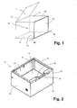
- Figur 1
- eine perspektivische und grob vereinfachte Ansicht eines kippbaren Garbehälters mit Deckel;
- Figur 2
- eine perspektivische praxisnähere Ansicht einer Form der Erfindung;
- Figur 3
- eine vergrößerte Darstellung des Bereiches des Ausgusses aus der
Figur 2 ; - Figur 4
- eine Darstellung des Ausgusses aus der
Figur 3 , gesehen vom Garraum aus; - Figur 5
- eine schematische Seitenansicht eines Garbehälters in Ruheposition; und
- Figur 6
- eine Darstellung des Garbehälters aus
Figur 5 während eines Kippvorgangs.
- FIG. 1
- a perspective and simplistic view of a tiltable cooking container with lid;
- FIG. 2
- a perspective more practical view of a form of the invention;
- FIG. 3
- an enlarged view of the area of the spout from the
FIG. 2 ; - FIG. 4
- a representation of the spout from the
FIG. 3 , seen from the oven; - FIG. 5
- a schematic side view of a cooking vessel in rest position; and
- FIG. 6
- a representation of the cooking vessel
FIG. 5 during a tipping process.
In der
Die Rückwand 12, die beiden Seitenwände 13 und 14 und die Vorderwand 15 sind jeweils Doppelwände. Zwischen der dem Garraum 16 zugewandten Innenwand und der dem Außenraum zugwandten Außenwand können Aggregate, eine Wärmedämmung und dergleichen angeordnet sein.The
Der Garraum 16 muss nicht zwingend würfel- oder quaderförmig wie in der
In dem Garraum 16 werden insbesondere Nahrungsmittel zubereitet, also unter anderem erhitzt, gegebenenfalls auch gerührt und bewegt, was hier nicht dargestellt ist.In the
In vielen Ausführungsformen wird dabei ein Deckel 17 vorgesehen, der über eine Gelenkachse 18 schwenkbar mit der Oberkante 30 der Rückwand 12 verbunden ist. Der Deckel 17 kann während des Garvorganges die offene Oberseite des Garbehälters 10 abdecken und somit den Garraum 16 zu einem vollständig umschlossenen Innenraum gestalten, in dem auch gezielt ein Überdruck herstellbar ist, wenn dieser für die Zubereitung des Nahrungsmittels im Garraum 16 gewünscht wird.In many embodiments, a
Der Deckel 17 liegt dabei auf der Oberkante der Rückwand 12, der beiden Seitenwände 13 und 14 und der Vorderwand 15 auf und ist durch geeignete, nicht dargestellte Elemente druckdicht verschlossen.The
Nicht dargestellt ist auch, dass etwa Zuführleitungen für die Zugabe von Wasser oder Zutaten (Zucker, Gewürze) in der Wandung des Garbehälters 10 oder des Deckels 17 vorgesehen sein können.It is also not shown that about feed lines for the addition of water or ingredients (sugar, spices) in the wall of the
Als Nahrungsmittel kommen insbesondere flüssige, cremige oder schüttfähige Nahrungsmittel in Betracht, beispielsweise Suppen, Soßen, Rührei, Süßspeisen, Reis oder Erbsen.Suitable foods are, in particular, liquid, creamy or pourable foods, for example soups, sauces, scrambled eggs, desserts, rice or peas.
Nachdem der Garvorgang fast oder ganz abgeschlossen ist, ist es erforderlich, die nunmehr zubereiteten Nahrungsmittel beziehungsweise Speisen aus dem Garraum 16 zu entnehmen und in andere Aufnahmebehälter oder Gerätschaften zu überführen, damit entweder der Zubereitungsvorgang in anderer Form fortgesetzt werden kann, oder auch damit die fertig zubereiteten Speisen zum Verzehr abtransportiert werden können.After the cooking process is almost or completely completed, it is necessary to remove the now prepared food or food from the
Gerade bei flüssigen, cremigen oder schüttfähigen Nahrungsmitteln beziehungsweise Speisen ist es dabei vorteilhaft, wenn der Garbehälter 10 mit samt der in ihm befindlichen Nahrungsmittel gekippt werden kann, und zwar vorzugsweise um eine Achse 20. Da der Deckel 17 wie in der dargestellten Grobskizze um eine Gelenkachse 18 an der Rückwand 12 schwenkbar ist, wird zweckmäßig die Kippachse 20 parallel zu dieser Gelenkachse 18 vorgesehen, und zwar im Bereich der Vorderwand 15, beispielsweise und bevorzugt im Bereich der Unterkante der Vorderwand 15, wo diese auf den Boden 11 trifft.Especially with liquid, creamy or pourable food or food, it is advantageous if the
Wird der Garbehälter 11 um diese Drehachse 20 nach oben und in der Darstellung in der
Während des Kippvorganges ist die Oberkante 30 der Vorderwand 15 der auf dem tiefsten Niveau liegende Bereich der umlaufenden Kante des Garbehälters 10, sodass dort (und nur dort) der Inhalt aus dem Garraum 16 herausgelangt.During the tilting process, the
Durch fortgesetztes weiteres Kippen kann kontinuierlich der gesamte Inhalt des Garraums 16 über diese Oberkante 30 der Vorderwand 15 hinaus ausgegossen werden.By continuing further tilting, the entire contents of the
Wenn der Kippvorgang einen Kippwinkel von 90° erreicht hat, bildet die Vorderwand 15 des Garbehälters 10 eine horizontale untere Fläche des Garraums 16, der sich mithin zu diesem Zeitpunkt vollständig über die Oberkante 30 entleert.When the tilting has reached a tilt angle of 90 °, the
Diese prinzipielle Darstellung zeigt zugleich schon ein auftretendes Problem: Der Ausgießvorgang würde über die komplette Oberkante 30 erfolgen und damit nicht in kleinere Behälter erfolgen können, die vor der Vorderwand 15 stehen. Darüber hinaus würde auch in den Eckbereichen der Vorderwand 15 und der Seitenwände 13 und 14 auch eine Teilmenge des ausströmenden Nahrungsmittels beziehungsweise Garguts über diese Randbereiche der Oberkanten der Seitenwände 13 und 14 hinweg seitlich ausströmen. Zu berücksichtigen ist ja, dass die ausströmende Menge des Nahrungsmittels eine endliche Höhe besitzt und nicht Null beträgt. Der ausflie-βende Strom kann sogar durchaus je nach Kippgeschwindigkeit eine Höhe von 1 oder mehren Zentimetern besitzen.At the same time, this basic representation already shows an occurring problem: the pouring process would take place over the complete
Um diesem Phänomen zu begegnen, wird jetzt eine in der
Gut zu erkennen ist, dass die Wandung des Garbehälters 10, also Rückwand 12, Seitenwände 13 und 14 sowie Vorderwand 15, eine endliche Dicke haben, da sie nämlich doppelwandig ausgebildet sind. Das bedeutet auch, dass der obere Rand oder die umlaufende Kante, auf der der nicht dargestellte Deckel 17 aufliegt, auch umlaufend eine endliche Breite besitzt und überwiegend eben und in gleicher Höhe ausgebildet ist.Good to see that the wall of the
Der Ausgießvorgang während des Kippens des Garbehälters 10 würde wiederum über die Vorderwand 15 erfolgen, in der
Man erkennt, dass die Oberkante 30 in diesem Bereich besonders ausgestaltet ist.It can be seen that the
Die Oberkante 30 ist im mittleren Bereich der Vorderwand 15 eindeutig schmaler oder dünner ausgebildet, als in den Bereichen der Vorderwand 15, die den Ecken zu den Seitenwänden 13 und 14 näher sind.The
Die Oberkante 30 ist darüber hinaus flach und weitgehend eben, was man in der perspektivischen Darstellung nur ungefähr erkennen kann.The
Aus diesem flachen und ebenen Bereich ragen zwei Leitelemente 32 und 33 nach oben heraus. Diese Leitelemente 32 und 33 sind links und rechts von dem mittleren Bereich mit der schmaleren Oberkante 30 angeordnet. Dieser mittlere Bereich ist ein Ausguss 31, der also von den beiden Leitelementen 32 und 33 links und rechts begrenzt wird.For this flat and planar area, two
Die Leitelemente 32 und 33 stehen schräg zur Oberkante 30, und zwar derart, dass sie genau eine Grenze der Oberkante 30 zu dem verengten mittleren Bereich der Oberkante 30 im Bereich des Ausgusses 31 bilden. Der Ausguss 31 läuft also schräg in Ausgießrichtung zu.The
Der Abstand zwischen den beiden Leitelementen 32 und 33 zwischen den Punkten, an denen sie sich am nächsten liegen, beträgt in bevorzugten Ausführungsformen zumindest 50 mm. Da hier der Ausguss 31 in seiner Breite begrenzt wird, sollte er zur Erzielung eines realistischen und in der Praxis brauchbaren Volumenstroms nicht nur eine bestimmte Mindesttiefe, sondern auch eine entsprechende Breite besitzen. Diese Breite ist natürlich auch maßgebend für die Auswahl von möglicherweise kleinen Behältern, die vor dem Ausguss 31 zur Aufnahme des herausströmenden Garguts vorzusehen sind.The distance between the two
Die Leitelemente haben in der dargestellten Ausführungsform eine Höhe von weniger als 30 mm. Dies hat den Vorteil, dass sie noch innerhalb des (nicht dargestellten) Deckels 17 während des Garvorganges aufgenommen werden können, jedoch bereits eine Höhe besitzen, die schon einen relevanten positiven Effekt auf den Volumenstrom hat.The guide elements have a height of less than 30 mm in the illustrated embodiment. This has the advantage that they can still be accommodated within the lid (not shown) 17 during the cooking process, but already have a height that already has a relevant positive effect on the volume flow.
Zu bedenken ist ja, dass das Gargut aus dem Inneren des Garraums 16 auch dann noch herausströmen soll, wenn der Garbehälter 10 seinen Kippvorgang nahezu beendet hat und der in der
Angedeutet sieht man schon ein zusätzliches Element, nämlich eine Tropfkante 41, die noch im Zusammenhang mit
In der
Man sieht hier vergrößert die Vorderwand 15 und die ebene und horizontale Oberkante 30.It can be seen enlarged here the
Die Oberkante 30 ist in ihrem mittleren Bereich wesentlich schmaler ausgebildet, da dort der Ausguss 31 vorgesehen ist. Der Ausguss 31 ist von den Leitelementen 32 und 33 begrenzt, die aus der Oberkante 30 nach oben heraus ragen und eine Art "Ohren" bilden.The
Auf der vom Betrachter abgewandten Seite der Vorderwand 15 befindet sich der Garraum 16.On the side facing away from the viewer side of the
Man kann bereits gut erkennen, dass fertigungstechnisch eine solche Konzeption recht praktisch herzustellen ist und das auch die Reinigungsvorgänge deutlich vereinfacht werden, da die Zahl der Hinterschneidungen und Nuten sehr gering gehalten ist.It is already easy to see that production engineering such a conception is quite practical to produce and also the cleaning operations are significantly simplified, since the number of undercuts and grooves is kept very low.
Wenn man sich den Ausgießvorgang vorstellt, so erkennt man, dass zwischen den beiden Leitelementen 32 und 33 der Volumenstrom sehr praktisch über den relativ schmalen, verbleibenden Bereich der Oberkante 30 hinweg strömen kann.If one imagines the pouring process, it can be seen that between the two
Man sieht, dass die Oberkante 30 zur Außenseite der Vorderwand 15 hin abgerundet ist. Diese Abrundung erleichtert die Trennung des Volumenstroms von dem Metallmaterial des Garbehälters 10.It can be seen that the
Man sieht ferner, dass als zusätzlicher Schutz noch eine Tropfkante 41 um einige Millimeter unterhalb der Kante 30 angeordnet ist, und zwar nur im Bereich des Ausgusses 31. Diese Tropfkante 41 fängt noch verbleibende geringfügige Resttropfen des Volumenstroms auf. Zu beachten ist auch hier wiederum, dass während des Kippvorganges natürlich die Lage der einzelnen Flächen sich ändert und auch anders ist als in der Darstellung; so ist die horizontale obere Kante 30 dann nicht mehr horizontal, wenn der Garbehälter 10 um eine in der
In der
Die Tiefe der Rinne 36 nimmt also von unten nach oben zu. Sie beträgt in einer praktischen Ausführungsform in Höhe der oberen Kante 30 etwa 50 mm. 50 mm sind etwa 2/3 oder ca. 70 % der Stärke der gesamten Wandung der Vorderwand 15, also der Garraumfront. Es bleiben also auch im Bereich des Abflusses etwa 30 % der oberen Kante 30 stehen, die für die Abdichtung während des Garvorganges nutzbar sind.The depth of the
Der Abfluss 31 mit seiner Rinne 36 wird durch zwei Seitenflächen 34 und 35 links und rechts mit den nicht modifizierten Bereichen der Wandung der Vorderwand 15 verbunden. Diese Seitenflächen stehen ebenfalls schräg und zwar derart, dass die Breite der Rinne 36 des Abflusses 31 sich von unten nach oben reduziert.The
Besonders auffallend ist, dass diese Seitenflächen 34 und 35 nach oben über die obere Kante 30 der Vorderwand 15 hinausragen. Die Seitenflächen 34 und 35 gehen hier in Leitflächen über, die von den Leitelementen 32 und 33 gebildet werden. In der dargestellten bevorzugten Ausführungsform der Erfindung sind also die Seitenflächen 34 und 35 des Ausgusses 31 und die jeweils zugeordnete Leitfläche der Leitelemente 32 und 33 in einer Ebene.It is particularly noticeable that these side surfaces 34 and 35 protrude upward above the
Zugleich bilden die oberen Begrenzungslinien der Leitelemente 32 und 33 mithin auch die oberen Grenzen dieser Seitenflächen 34 und 35 beziehungsweise Leitflächen.At the same time, the upper boundary lines of the
Man sieht in der Figur sehr deutlich, dass ein Volumenstrom aus dem Garraum 16 heraus deutlich kanalisiert wird und während des Kippvorganges eine gezielte und ungehinderte Richtung einnimmt, die auch gut vorhersehbar ist.It can be seen very clearly in the figure that a volume flow from the
Besondere Aufmerksamkeit sollte dabei dem Gedanken gewidmet werden, dass während des Kippvorganges durch die Leitflächen der Leitelemente 32 und 33 der Volumenstrom des ausgegossenen Gargutes eine bedeutend größere Höhe erreichen kann, als ohne diese Leitelemente 32 und 33. Diese verhindern nämlich, dass das Gargut während des Ausgießvorganges bei gleicher Höhe sich nach links und rechts über die Oberkante 30 hinweg in einer größeren Breite über die Vorderwand 15 hinweg ergießen kann.Particular attention should be given to the idea that during the tipping process by the guide surfaces of the
Außerhalb der Leitelemente 32 und 33 kann kein Gargut über die Kante 30 strömen, wenn der Kippvorgang kontinuierlich durchgeführt wird, da dort während des Kippens durch die Innenseite der Vorderwand 15 eine größere Höhe aufgebaut wird.Outside the
Um dies noch etwas deutlicher zu machen, ist in der
Man sieht rechts in der Vorderwand 15 schematisch angedeutet, dass dort eine Rinne für den Ausguss 31 vom Boden 11 schräg in der Vorderwand 15 nach oben läuft und sich oberhalb der Oberkante 30 der Vorderwand 15 Leitelemente 32, 33 erstrecken. In diesem Zustand kann kein Gargut ausströmen.It can be seen right in the
Es wird jetzt ein Kippvorgang in der
In dem nun schräg stehenden Garbehälter 10 wird durch das Anheben des Bodens 11 für das Gargut unterhalb der Füllhöhe 51 das Volumen knapp und entsprechend steigt das Volumen relativ zu der nun am tiefsten liegenden oberen Kante 30 der Vorderwand 15.In the now inclined
Man kann nun gut erkennen, dass in den Bereichen der Vorderwand 15 außerhalb des Ausgusses 31 die Füllstandshöhe 51 recht genau bis gerade zur dem Garraum 16 benachbarten Seite der oberen Kante 30 reicht. Hier kann also noch nichts über die Oberkante 30 hinwegschappen.It can now be clearly seen that, in the areas of the
In dem Bereich des Ausgusses 31 dagegen ist die maximal mögliche Füllhöhe des Gargutes niedriger, da sie dort in die Rinne des Ausgusses 31 hinein ragt und die aufgrund des Kippvorganges noch etwas tiefer liegenden Bereiche der oberen Kante 30 benachbart zum Außenraum erreicht.In the region of the
Der Unterschied hV ist also diejenige Höhe des Gargutes, die als Strom während des Kippvorganges in diesem Moment den Garbehälter 10 verlässt und nach außen abfließt. Der Unterschied hV ist zugleich der Höhenunterschied zwischen dem höchsten, dem Garraum 16 benachbarten Punkt beziehungsweise der Linie der oberen Kante 30 einerseits sowie der an die Rinne des Ausgusses 31 angrenzenden Linie der oberen Kante 30 der zum Ausgießen vorgesehenen Vorderwand 15, und zwar gesehen im jeweils aktuellen Kippzustand des Garbehälters 10.The difference h V is therefore the height of the food that leaves the
Der Unterschied hV ändert sich also während des Kippvorgangs; er nimmt während des Ausgießvorgangs kontinuierlich zu. Das hat auch den Vorteil, dass mit abnehmendem Gargutinhalt im Garraum 16 die Möglichkeit zum Abströmenlassen des Restinhalts sich verbessert, so dass insbesondere auch der Gargutstrom kurz vor der endgültigen Entleerung nicht wie gelegentlich im Stand der Technik üblich nur noch mühsam kommt, da aufgrund der geringen verbliebenen Restinhaltmenge wenig "Nachdruck" erfolgt.The difference h V thus changes during the tilting process; it increases continuously during the pouring process. This also has the advantage that with decreasing Gargutinhalt in the
Alle vorgenannten Überlegungen zu diesem Unterschied hV gelten nur für den Bereich des Ausgusses 31, da nur hier das Gargut bis in diesen Bereich der oberen Kante 30 gelangen kann.All the above considerations on this difference h V apply only to the region of the
Damit wird jetzt die Funktion der bevorzugt dreieckigen Leitelemente 32 und 33 deutlich. Diese sorgen für genau den Übergangsbereich zwischen der ungestörten Vorderwand 15 mit der oberen Kante 30 in voller Breite und der Rinne des Ausgusses 31 dafür, dass die in diesem Bereich dichter als im ungestörten Bereich der Vorderwand 15 an die Außenlinie der Oberkante 30 heranreichenden Teile des Gargutes gleichwohl keine Möglichkeit besteht, außerhalb des vorgesehenen Ausgusses 31 etwa seitlich auf die obere Kante 30 zu gelangen und somit die Vorderwand 15 in seinem nicht beabsichtigten und nicht gewünschten Bereich zu verlassen.Thus, the function of the preferably
Zugleich wird der Volumenstrom des ausgegossenen Gargutes kanalisiert und durch die Leitelemente 32 und 33 in einen stabilen und sauberen und auch zielgenauen Strahl fokussiert.At the same time, the volume flow of the poured food is channeled and focused by the
Dies wird verstärkt, wenn der Ausguss 31 mit seiner Rinne 36 und den Seitenflächen und Gleitflächen der Leitelemente so ausgebildet ist, wie dies in den
Man könnte die Formulierung für die Leitelemente auch etwa so wählen: Die Oberkante der Leitelemente 32 und 33 bildet bei beginnendem Ausgießvorgang mit noch maximalem Gargutvolumen Verlängerungen des Gargutniveaus. Beginnt nun der Ausgießvorgang, so bilden der Ausguss und die Leitelemente 32 und 33 einen Freiraum unterhalb der Füllstandshöhe 51 des Gargutes von mindestens der erwünschten Volumenstromhöhe im Zentrum des Ausgusses 31. Diese erwünschte Volumenstromhöhe liegt in einer Größenordnung von zumindest 10 mm. Die Leitelemente verhindern dabei ein seitliches Abfließen des Gargutvolumenstroms.The formulation for the guide elements could also be chosen approximately as follows: The upper edge of the
Da sich der Ausguss 31 vom Boden 11 zur oberen Kante 30 der Vorderwand 15 hin verengt, verringert sich auch der Abstand zwischen den Seitenwänden des Ausgusses 31 und auch der Abstand zwischen den beiden Leitflächen der Leitelemente 32 und 33. Durch die Kanalisierung entsteht sogar ein Gargutstrahl, dessen Breite während des Ausgießvorgangs kleiner ist als die Breite des Ausgusses 31.As the
- 1010
- Garbehältercooking containers
- 1111
- Bodenground
- 1212
- Rückwandrear wall
- 1313
- SeitenwandSide wall
- 1414
- SeitenwandSide wall
- 1515
- Vorderwandfront wall
- 1616
- Garraumoven
- 1717
- Deckelcover
- 1818
- Genlenkachse des DeckelsGenlenkachse of the lid
- 2020
-
Kippachse des Garbehälters 10Tilting axis of the
cooking container 10 - 3030
-
Oberkante der Seitenwand 15Top edge of the
side wall 15 - 3131
- Ausgussspout
- 3232
- Leitelementvane
- 3333
- Leitelementvane
- 3434
-
Seitenwand des Ausgusses 31Side wall of the
spout 31 - 3535
-
Seitenwand des Ausgusses 31Side wall of the
spout 31 - 3636
- Rinnegutter
- 4141
- Abtropfkantedrip
- 5151
- Füllstandshöhefilling level
Claims (9)
dadurch gekennzeichnet,
dass an der Kante (30) auf beiden Seiten des Ausgusses (31) jeweils mindestens ein Leitelement (32, 33) angeordnet ist, das über die zugehörige Wand (15) vorsteht bzw. vorspringt.Food cooking appliance comprising a cooking container (10) having a front wall (15), a rear wall (12), two side walls (13, 14) and a bottom (11) which together form a cooking space (16), wherein a lid (17) is provided, which is able to close the cooking chamber (16), wherein the cooking container (10) about a tilting axis (20) for emptying the cooking chamber (16) is tiltable, wherein for emptying the cooking chamber (16) an upper edge (30) of one of the walls (12, 13, 14, 15) is provided, in which a spout (31) is formed, wherein the spout (31) extends towards the upper edge (30) narrowing channel (36) which in the direction from the bottom (11) to the edge (30) has an inclination to the associated wall (15).
characterized,
in that at least one guide element (32, 33) is projected on the edge (30) on both sides of the spout (31) and protrudes beyond the associated wall (15).
Applications Claiming Priority (1)
| Application Number | Priority Date | Filing Date | Title |
|---|---|---|---|
| DE102011116273A DE102011116273B4 (en) | 2011-10-19 | 2011-10-19 | Cooking appliance with a cooking tray tiltable about a tilting axis |
Publications (2)
| Publication Number | Publication Date |
|---|---|
| EP2583594A1 true EP2583594A1 (en) | 2013-04-24 |
| EP2583594B1 EP2583594B1 (en) | 2014-04-09 |
Family
ID=47115438
Family Applications (1)
| Application Number | Title | Priority Date | Filing Date |
|---|---|---|---|
| EP20120189083 Not-in-force EP2583594B1 (en) | 2011-10-19 | 2012-10-18 | Cooking device with a cooking container which tilts around a tilting axis |
Country Status (2)
| Country | Link |
|---|---|
| EP (1) | EP2583594B1 (en) |
| DE (1) | DE102011116273B4 (en) |
Families Citing this family (2)
| Publication number | Priority date | Publication date | Assignee | Title |
|---|---|---|---|---|
| DE102019124153A1 (en) * | 2019-09-09 | 2021-03-11 | Rational Wittenheim Sas | Cooking device crucible |
| EP3854273B1 (en) | 2020-01-22 | 2023-07-05 | MKN Maschinenfabrik Kurt Neubauer GmbH & Co. KG | Cooking appliance for large kitchen |
Citations (6)
| Publication number | Priority date | Publication date | Assignee | Title |
|---|---|---|---|---|
| DE6914432U (en) * | 1969-04-09 | 1969-10-02 | Senkingwerk | TILTING FRY PAN, STORED ON COLUMN AND CONSOLE |
| US3797377A (en) * | 1972-05-18 | 1974-03-19 | South Bend Range Corp | Tiltable cooking pan |
| US3964378A (en) * | 1974-03-22 | 1976-06-22 | The Frymaster Corporation | Tilting frypan with drain system |
| DE3525845A1 (en) | 1984-10-19 | 1986-04-24 | Robert Mauch Elro-Werke AG, Bremgarten | Tiltable vessel having a trough |
| EP1488721A1 (en) * | 2003-06-18 | 2004-12-22 | Frima S.A. | Well-like container for a fryer and fryer |
| JP2007285546A (en) * | 2006-04-13 | 2007-11-01 | Nichiwa Denki Kk | Cooker |
Family Cites Families (1)
| Publication number | Priority date | Publication date | Assignee | Title |
|---|---|---|---|---|
| FR2070617A5 (en) * | 1969-12-11 | 1971-09-10 | Gentilini Et Berthon |
-
2011
- 2011-10-19 DE DE102011116273A patent/DE102011116273B4/en not_active Expired - Fee Related
-
2012
- 2012-10-18 EP EP20120189083 patent/EP2583594B1/en not_active Not-in-force
Patent Citations (6)
| Publication number | Priority date | Publication date | Assignee | Title |
|---|---|---|---|---|
| DE6914432U (en) * | 1969-04-09 | 1969-10-02 | Senkingwerk | TILTING FRY PAN, STORED ON COLUMN AND CONSOLE |
| US3797377A (en) * | 1972-05-18 | 1974-03-19 | South Bend Range Corp | Tiltable cooking pan |
| US3964378A (en) * | 1974-03-22 | 1976-06-22 | The Frymaster Corporation | Tilting frypan with drain system |
| DE3525845A1 (en) | 1984-10-19 | 1986-04-24 | Robert Mauch Elro-Werke AG, Bremgarten | Tiltable vessel having a trough |
| EP1488721A1 (en) * | 2003-06-18 | 2004-12-22 | Frima S.A. | Well-like container for a fryer and fryer |
| JP2007285546A (en) * | 2006-04-13 | 2007-11-01 | Nichiwa Denki Kk | Cooker |
Also Published As
| Publication number | Publication date |
|---|---|
| DE102011116273B4 (en) | 2013-12-12 |
| DE102011116273A1 (en) | 2013-04-25 |
| EP2583594B1 (en) | 2014-04-09 |
Similar Documents
| Publication | Publication Date | Title |
|---|---|---|
| EP2393401B1 (en) | Closure for a beverage container | |
| EP0227977B1 (en) | Coffee maker | |
| EP2341803B1 (en) | Beverage preparation device comprising an insert inserted into a receptacle | |
| DE3720149A1 (en) | COFFEE MACHINE | |
| WO1990009133A1 (en) | Cooking receptacle | |
| EP2583594B1 (en) | Cooking device with a cooking container which tilts around a tilting axis | |
| EP0220688B1 (en) | Machine for making coffee or tea | |
| DE7915161U1 (en) | Coffee and / or espresso machine | |
| DE102011002821A1 (en) | strainer | |
| EP0916900B1 (en) | Baking tin | |
| DE102005047663B4 (en) | Splash guard for a pan | |
| EP3195767B1 (en) | Beverage preparer with cup table | |
| DE202004009759U1 (en) | cafetiere | |
| DE102006049893B3 (en) | Holding device for use in beverage machine, comprises dripping plate and cup body that is formed between upper and lower position for adjusting and turning | |
| DE19907072B4 (en) | fryer | |
| EP3854273B1 (en) | Cooking appliance for large kitchen | |
| DE102010046783B4 (en) | Container lid for optimized emptying of a vessel, in particular cooking pot lid for a cooking pot | |
| EP3113659B1 (en) | Vessel for the preparation of infusion beverages | |
| DE202004006760U1 (en) | Container for cream for coffee or for tea is in form of spoon with handle which has foil seal over its rim | |
| EP0306679A2 (en) | Vessel, in particular a thermally insulated vessel | |
| DE4413282A1 (en) | Electric jug kettle with lid insert | |
| DE202011101102U1 (en) | Saucepan with pouring sieve | |
| DE102012222029A1 (en) | Liquid container for supplying fluid to e.g. steam cooker, has one vent opening whose storage volume-side beginning is located lower in vertical direction than beginning of other opening during intended filling alignment of container | |
| DE102012000901B4 (en) | Cooking container with removable strainer | |
| EP0053234A1 (en) | Thermally-insulating lid for a thermos flask |
Legal Events
| Date | Code | Title | Description |
|---|---|---|---|
| PUAI | Public reference made under article 153(3) epc to a published international application that has entered the european phase |
Free format text: ORIGINAL CODE: 0009012 |
|
| AK | Designated contracting states |
Kind code of ref document: A1 Designated state(s): AL AT BE BG CH CY CZ DE DK EE ES FI FR GB GR HR HU IE IS IT LI LT LU LV MC MK MT NL NO PL PT RO RS SE SI SK SM TR |
|
| AX | Request for extension of the european patent |
Extension state: BA ME |
|
| RAP1 | Party data changed (applicant data changed or rights of an application transferred) |
Owner name: MKN MASCHINENFABRIK KURT NEUBAUER GMBH & CO. KG |
|
| 17P | Request for examination filed |
Effective date: 20131021 |
|
| RBV | Designated contracting states (corrected) |
Designated state(s): AL AT BE BG CH CY CZ DE DK EE ES FI FR GB GR HR HU IE IS IT LI LT LU LV MC MK MT NL NO PL PT RO RS SE SI SK SM TR |
|
| 17Q | First examination report despatched |
Effective date: 20131118 |
|
| GRAP | Despatch of communication of intention to grant a patent |
Free format text: ORIGINAL CODE: EPIDOSNIGR1 |
|
| INTG | Intention to grant announced |
Effective date: 20131220 |
|
| GRAS | Grant fee paid |
Free format text: ORIGINAL CODE: EPIDOSNIGR3 |
|
| GRAA | (expected) grant |
Free format text: ORIGINAL CODE: 0009210 |
|
| AK | Designated contracting states |
Kind code of ref document: B1 Designated state(s): AL AT BE BG CH CY CZ DE DK EE ES FI FR GB GR HR HU IE IS IT LI LT LU LV MC MK MT NL NO PL PT RO RS SE SI SK SM TR |
|
| REG | Reference to a national code |
Ref country code: GB Ref legal event code: FG4D Free format text: NOT ENGLISH |
|
| REG | Reference to a national code |
Ref country code: CH Ref legal event code: EP Ref country code: AT Ref legal event code: REF Ref document number: 660844 Country of ref document: AT Kind code of ref document: T Effective date: 20140415 |
|
| REG | Reference to a national code |
Ref country code: IE Ref legal event code: FG4D Free format text: LANGUAGE OF EP DOCUMENT: GERMAN |
|
| REG | Reference to a national code |
Ref country code: DE Ref legal event code: R096 Ref document number: 502012000573 Country of ref document: DE Effective date: 20140522 |
|
| REG | Reference to a national code |
Ref country code: NL Ref legal event code: VDEP Effective date: 20140409 |
|
| REG | Reference to a national code |
Ref country code: LT Ref legal event code: MG4D |
|
| PG25 | Lapsed in a contracting state [announced via postgrant information from national office to epo] |
Ref country code: LT Free format text: LAPSE BECAUSE OF FAILURE TO SUBMIT A TRANSLATION OF THE DESCRIPTION OR TO PAY THE FEE WITHIN THE PRESCRIBED TIME-LIMIT Effective date: 20140409 Ref country code: BG Free format text: LAPSE BECAUSE OF FAILURE TO SUBMIT A TRANSLATION OF THE DESCRIPTION OR TO PAY THE FEE WITHIN THE PRESCRIBED TIME-LIMIT Effective date: 20140709 Ref country code: NL Free format text: LAPSE BECAUSE OF FAILURE TO SUBMIT A TRANSLATION OF THE DESCRIPTION OR TO PAY THE FEE WITHIN THE PRESCRIBED TIME-LIMIT Effective date: 20140409 Ref country code: IS Free format text: LAPSE BECAUSE OF FAILURE TO SUBMIT A TRANSLATION OF THE DESCRIPTION OR TO PAY THE FEE WITHIN THE PRESCRIBED TIME-LIMIT Effective date: 20140809 Ref country code: NO Free format text: LAPSE BECAUSE OF FAILURE TO SUBMIT A TRANSLATION OF THE DESCRIPTION OR TO PAY THE FEE WITHIN THE PRESCRIBED TIME-LIMIT Effective date: 20140709 Ref country code: FI Free format text: LAPSE BECAUSE OF FAILURE TO SUBMIT A TRANSLATION OF THE DESCRIPTION OR TO PAY THE FEE WITHIN THE PRESCRIBED TIME-LIMIT Effective date: 20140409 Ref country code: GR Free format text: LAPSE BECAUSE OF FAILURE TO SUBMIT A TRANSLATION OF THE DESCRIPTION OR TO PAY THE FEE WITHIN THE PRESCRIBED TIME-LIMIT Effective date: 20140710 |
|
| PG25 | Lapsed in a contracting state [announced via postgrant information from national office to epo] |
Ref country code: PL Free format text: LAPSE BECAUSE OF FAILURE TO SUBMIT A TRANSLATION OF THE DESCRIPTION OR TO PAY THE FEE WITHIN THE PRESCRIBED TIME-LIMIT Effective date: 20140409 Ref country code: RS Free format text: LAPSE BECAUSE OF FAILURE TO SUBMIT A TRANSLATION OF THE DESCRIPTION OR TO PAY THE FEE WITHIN THE PRESCRIBED TIME-LIMIT Effective date: 20140409 Ref country code: LV Free format text: LAPSE BECAUSE OF FAILURE TO SUBMIT A TRANSLATION OF THE DESCRIPTION OR TO PAY THE FEE WITHIN THE PRESCRIBED TIME-LIMIT Effective date: 20140409 Ref country code: SE Free format text: LAPSE BECAUSE OF FAILURE TO SUBMIT A TRANSLATION OF THE DESCRIPTION OR TO PAY THE FEE WITHIN THE PRESCRIBED TIME-LIMIT Effective date: 20140409 Ref country code: ES Free format text: LAPSE BECAUSE OF FAILURE TO SUBMIT A TRANSLATION OF THE DESCRIPTION OR TO PAY THE FEE WITHIN THE PRESCRIBED TIME-LIMIT Effective date: 20140409 Ref country code: HR Free format text: LAPSE BECAUSE OF FAILURE TO SUBMIT A TRANSLATION OF THE DESCRIPTION OR TO PAY THE FEE WITHIN THE PRESCRIBED TIME-LIMIT Effective date: 20140409 |
|
| PG25 | Lapsed in a contracting state [announced via postgrant information from national office to epo] |
Ref country code: PT Free format text: LAPSE BECAUSE OF FAILURE TO SUBMIT A TRANSLATION OF THE DESCRIPTION OR TO PAY THE FEE WITHIN THE PRESCRIBED TIME-LIMIT Effective date: 20140811 |
|
| REG | Reference to a national code |
Ref country code: DE Ref legal event code: R097 Ref document number: 502012000573 Country of ref document: DE |
|
| PG25 | Lapsed in a contracting state [announced via postgrant information from national office to epo] |
Ref country code: EE Free format text: LAPSE BECAUSE OF FAILURE TO SUBMIT A TRANSLATION OF THE DESCRIPTION OR TO PAY THE FEE WITHIN THE PRESCRIBED TIME-LIMIT Effective date: 20140409 Ref country code: RO Free format text: LAPSE BECAUSE OF FAILURE TO SUBMIT A TRANSLATION OF THE DESCRIPTION OR TO PAY THE FEE WITHIN THE PRESCRIBED TIME-LIMIT Effective date: 20140409 Ref country code: SK Free format text: LAPSE BECAUSE OF FAILURE TO SUBMIT A TRANSLATION OF THE DESCRIPTION OR TO PAY THE FEE WITHIN THE PRESCRIBED TIME-LIMIT Effective date: 20140409 Ref country code: DK Free format text: LAPSE BECAUSE OF FAILURE TO SUBMIT A TRANSLATION OF THE DESCRIPTION OR TO PAY THE FEE WITHIN THE PRESCRIBED TIME-LIMIT Effective date: 20140409 |
|
| PLBE | No opposition filed within time limit |
Free format text: ORIGINAL CODE: 0009261 |
|
| STAA | Information on the status of an ep patent application or granted ep patent |
Free format text: STATUS: NO OPPOSITION FILED WITHIN TIME LIMIT |
|
| 26N | No opposition filed |
Effective date: 20150112 |
|
| REG | Reference to a national code |
Ref country code: DE Ref legal event code: R097 Ref document number: 502012000573 Country of ref document: DE Effective date: 20150112 |
|
| PG25 | Lapsed in a contracting state [announced via postgrant information from national office to epo] |
Ref country code: MC Free format text: LAPSE BECAUSE OF FAILURE TO SUBMIT A TRANSLATION OF THE DESCRIPTION OR TO PAY THE FEE WITHIN THE PRESCRIBED TIME-LIMIT Effective date: 20140409 Ref country code: LU Free format text: LAPSE BECAUSE OF FAILURE TO SUBMIT A TRANSLATION OF THE DESCRIPTION OR TO PAY THE FEE WITHIN THE PRESCRIBED TIME-LIMIT Effective date: 20141018 |
|
| PG25 | Lapsed in a contracting state [announced via postgrant information from national office to epo] |
Ref country code: BE Free format text: LAPSE BECAUSE OF NON-PAYMENT OF DUE FEES Effective date: 20141031 |
|
| REG | Reference to a national code |
Ref country code: IE Ref legal event code: MM4A |
|
| PG25 | Lapsed in a contracting state [announced via postgrant information from national office to epo] |
Ref country code: SI Free format text: LAPSE BECAUSE OF FAILURE TO SUBMIT A TRANSLATION OF THE DESCRIPTION OR TO PAY THE FEE WITHIN THE PRESCRIBED TIME-LIMIT Effective date: 20140409 |
|
| REG | Reference to a national code |
Ref country code: FR Ref legal event code: PLFP Year of fee payment: 4 |
|
| PG25 | Lapsed in a contracting state [announced via postgrant information from national office to epo] |
Ref country code: IE Free format text: LAPSE BECAUSE OF NON-PAYMENT OF DUE FEES Effective date: 20141018 |
|
| PG25 | Lapsed in a contracting state [announced via postgrant information from national office to epo] |
Ref country code: CY Free format text: LAPSE BECAUSE OF FAILURE TO SUBMIT A TRANSLATION OF THE DESCRIPTION OR TO PAY THE FEE WITHIN THE PRESCRIBED TIME-LIMIT Effective date: 20140409 |
|
| PG25 | Lapsed in a contracting state [announced via postgrant information from national office to epo] |
Ref country code: MT Free format text: LAPSE BECAUSE OF FAILURE TO SUBMIT A TRANSLATION OF THE DESCRIPTION OR TO PAY THE FEE WITHIN THE PRESCRIBED TIME-LIMIT Effective date: 20140409 Ref country code: TR Free format text: LAPSE BECAUSE OF FAILURE TO SUBMIT A TRANSLATION OF THE DESCRIPTION OR TO PAY THE FEE WITHIN THE PRESCRIBED TIME-LIMIT Effective date: 20140409 Ref country code: HU Free format text: LAPSE BECAUSE OF FAILURE TO SUBMIT A TRANSLATION OF THE DESCRIPTION OR TO PAY THE FEE WITHIN THE PRESCRIBED TIME-LIMIT; INVALID AB INITIO Effective date: 20121018 |
|
| REG | Reference to a national code |
Ref country code: FR Ref legal event code: PLFP Year of fee payment: 5 |
|
| PG25 | Lapsed in a contracting state [announced via postgrant information from national office to epo] |
Ref country code: SM Free format text: LAPSE BECAUSE OF FAILURE TO SUBMIT A TRANSLATION OF THE DESCRIPTION OR TO PAY THE FEE WITHIN THE PRESCRIBED TIME-LIMIT Effective date: 20140409 |
|
| GBPC | Gb: european patent ceased through non-payment of renewal fee |
Effective date: 20161018 |
|
| PG25 | Lapsed in a contracting state [announced via postgrant information from national office to epo] |
Ref country code: GB Free format text: LAPSE BECAUSE OF NON-PAYMENT OF DUE FEES Effective date: 20161018 |
|
| REG | Reference to a national code |
Ref country code: FR Ref legal event code: PLFP Year of fee payment: 6 |
|
| PG25 | Lapsed in a contracting state [announced via postgrant information from national office to epo] |
Ref country code: MK Free format text: LAPSE BECAUSE OF FAILURE TO SUBMIT A TRANSLATION OF THE DESCRIPTION OR TO PAY THE FEE WITHIN THE PRESCRIBED TIME-LIMIT Effective date: 20140409 |
|
| REG | Reference to a national code |
Ref country code: FR Ref legal event code: PLFP Year of fee payment: 7 |
|
| PG25 | Lapsed in a contracting state [announced via postgrant information from national office to epo] |
Ref country code: AL Free format text: LAPSE BECAUSE OF FAILURE TO SUBMIT A TRANSLATION OF THE DESCRIPTION OR TO PAY THE FEE WITHIN THE PRESCRIBED TIME-LIMIT Effective date: 20140409 |
|
| REG | Reference to a national code |
Ref country code: AT Ref legal event code: MM01 Ref document number: 660844 Country of ref document: AT Kind code of ref document: T Effective date: 20171018 |
|
| PG25 | Lapsed in a contracting state [announced via postgrant information from national office to epo] |
Ref country code: AT Free format text: LAPSE BECAUSE OF NON-PAYMENT OF DUE FEES Effective date: 20171018 |
|
| PGFP | Annual fee paid to national office [announced via postgrant information from national office to epo] |
Ref country code: CZ Payment date: 20190926 Year of fee payment: 8 |
|
| PGFP | Annual fee paid to national office [announced via postgrant information from national office to epo] |
Ref country code: FR Payment date: 20191026 Year of fee payment: 8 Ref country code: IT Payment date: 20191031 Year of fee payment: 8 |
|
| PGFP | Annual fee paid to national office [announced via postgrant information from national office to epo] |
Ref country code: CH Payment date: 20191025 Year of fee payment: 8 |
|
| PGFP | Annual fee paid to national office [announced via postgrant information from national office to epo] |
Ref country code: DE Payment date: 20201028 Year of fee payment: 9 |
|
| REG | Reference to a national code |
Ref country code: CH Ref legal event code: PL |
|
| PG25 | Lapsed in a contracting state [announced via postgrant information from national office to epo] |
Ref country code: CZ Free format text: LAPSE BECAUSE OF NON-PAYMENT OF DUE FEES Effective date: 20201018 Ref country code: FR Free format text: LAPSE BECAUSE OF NON-PAYMENT OF DUE FEES Effective date: 20201031 |
|
| PG25 | Lapsed in a contracting state [announced via postgrant information from national office to epo] |
Ref country code: CH Free format text: LAPSE BECAUSE OF NON-PAYMENT OF DUE FEES Effective date: 20201031 Ref country code: LI Free format text: LAPSE BECAUSE OF NON-PAYMENT OF DUE FEES Effective date: 20201031 |
|
| PG25 | Lapsed in a contracting state [announced via postgrant information from national office to epo] |
Ref country code: IT Free format text: LAPSE BECAUSE OF NON-PAYMENT OF DUE FEES Effective date: 20201018 |
|
| REG | Reference to a national code |
Ref country code: DE Ref legal event code: R119 Ref document number: 502012000573 Country of ref document: DE |
|
| PG25 | Lapsed in a contracting state [announced via postgrant information from national office to epo] |
Ref country code: DE Free format text: LAPSE BECAUSE OF NON-PAYMENT OF DUE FEES Effective date: 20220503 |