EP2570657A1 - Wind turbine sound management - Google Patents
Wind turbine sound management Download PDFInfo
- Publication number
- EP2570657A1 EP2570657A1 EP12183567A EP12183567A EP2570657A1 EP 2570657 A1 EP2570657 A1 EP 2570657A1 EP 12183567 A EP12183567 A EP 12183567A EP 12183567 A EP12183567 A EP 12183567A EP 2570657 A1 EP2570657 A1 EP 2570657A1
- Authority
- EP
- European Patent Office
- Prior art keywords
- sound level
- wind turbine
- redefined
- operating
- desired sound
- Prior art date
- Legal status (The legal status is an assumption and is not a legal conclusion. Google has not performed a legal analysis and makes no representation as to the accuracy of the status listed.)
- Granted
Links
- 238000000034 method Methods 0.000 claims abstract description 61
- 238000005259 measurement Methods 0.000 claims description 16
- 230000006870 function Effects 0.000 description 40
- 238000004364 calculation method Methods 0.000 description 12
- 238000010586 diagram Methods 0.000 description 7
- 238000012546 transfer Methods 0.000 description 6
- 230000008878 coupling Effects 0.000 description 5
- 238000010168 coupling process Methods 0.000 description 5
- 238000005859 coupling reaction Methods 0.000 description 5
- 230000001419 dependent effect Effects 0.000 description 5
- 230000008859 change Effects 0.000 description 3
- 230000003068 static effect Effects 0.000 description 3
- 239000013598 vector Substances 0.000 description 3
- 230000008901 benefit Effects 0.000 description 2
- 230000000694 effects Effects 0.000 description 2
- 239000012530 fluid Substances 0.000 description 2
- 238000012986 modification Methods 0.000 description 2
- 230000004048 modification Effects 0.000 description 2
- 238000012806 monitoring device Methods 0.000 description 2
- 230000009467 reduction Effects 0.000 description 2
- 238000003860 storage Methods 0.000 description 2
- 229910000831 Steel Inorganic materials 0.000 description 1
- 238000013459 approach Methods 0.000 description 1
- 238000005094 computer simulation Methods 0.000 description 1
- 230000001276 controlling effect Effects 0.000 description 1
- 238000012937 correction Methods 0.000 description 1
- 230000003247 decreasing effect Effects 0.000 description 1
- 238000009826 distribution Methods 0.000 description 1
- 230000009977 dual effect Effects 0.000 description 1
- 230000005611 electricity Effects 0.000 description 1
- 230000006872 improvement Effects 0.000 description 1
- 238000009434 installation Methods 0.000 description 1
- 238000004519 manufacturing process Methods 0.000 description 1
- 238000013507 mapping Methods 0.000 description 1
- 230000007246 mechanism Effects 0.000 description 1
- 230000007935 neutral effect Effects 0.000 description 1
- 238000005457 optimization Methods 0.000 description 1
- 230000002093 peripheral effect Effects 0.000 description 1
- 230000002085 persistent effect Effects 0.000 description 1
- 238000010248 power generation Methods 0.000 description 1
- 230000008569 process Effects 0.000 description 1
- 230000001105 regulatory effect Effects 0.000 description 1
- 239000010959 steel Substances 0.000 description 1
- 230000007704 transition Effects 0.000 description 1
Images
Classifications
-
- F—MECHANICAL ENGINEERING; LIGHTING; HEATING; WEAPONS; BLASTING
- F03—MACHINES OR ENGINES FOR LIQUIDS; WIND, SPRING, OR WEIGHT MOTORS; PRODUCING MECHANICAL POWER OR A REACTIVE PROPULSIVE THRUST, NOT OTHERWISE PROVIDED FOR
- F03D—WIND MOTORS
- F03D7/00—Controlling wind motors
- F03D7/02—Controlling wind motors the wind motors having rotation axis substantially parallel to the air flow entering the rotor
- F03D7/0296—Controlling wind motors the wind motors having rotation axis substantially parallel to the air flow entering the rotor to prevent, counteract or reduce noise emissions
-
- F—MECHANICAL ENGINEERING; LIGHTING; HEATING; WEAPONS; BLASTING
- F03—MACHINES OR ENGINES FOR LIQUIDS; WIND, SPRING, OR WEIGHT MOTORS; PRODUCING MECHANICAL POWER OR A REACTIVE PROPULSIVE THRUST, NOT OTHERWISE PROVIDED FOR
- F03D—WIND MOTORS
- F03D13/00—Assembly, mounting or commissioning of wind motors; Arrangements specially adapted for transporting wind motor components
- F03D13/20—Arrangements for mounting or supporting wind motors; Masts or towers for wind motors
-
- F—MECHANICAL ENGINEERING; LIGHTING; HEATING; WEAPONS; BLASTING
- F03—MACHINES OR ENGINES FOR LIQUIDS; WIND, SPRING, OR WEIGHT MOTORS; PRODUCING MECHANICAL POWER OR A REACTIVE PROPULSIVE THRUST, NOT OTHERWISE PROVIDED FOR
- F03D—WIND MOTORS
- F03D80/00—Details, components or accessories not provided for in groups F03D1/00 - F03D17/00
-
- F—MECHANICAL ENGINEERING; LIGHTING; HEATING; WEAPONS; BLASTING
- F05—INDEXING SCHEMES RELATING TO ENGINES OR PUMPS IN VARIOUS SUBCLASSES OF CLASSES F01-F04
- F05B—INDEXING SCHEME RELATING TO WIND, SPRING, WEIGHT, INERTIA OR LIKE MOTORS, TO MACHINES OR ENGINES FOR LIQUIDS COVERED BY SUBCLASSES F03B, F03D AND F03G
- F05B2270/00—Control
- F05B2270/30—Control parameters, e.g. input parameters
- F05B2270/333—Noise or sound levels
-
- Y—GENERAL TAGGING OF NEW TECHNOLOGICAL DEVELOPMENTS; GENERAL TAGGING OF CROSS-SECTIONAL TECHNOLOGIES SPANNING OVER SEVERAL SECTIONS OF THE IPC; TECHNICAL SUBJECTS COVERED BY FORMER USPC CROSS-REFERENCE ART COLLECTIONS [XRACs] AND DIGESTS
- Y02—TECHNOLOGIES OR APPLICATIONS FOR MITIGATION OR ADAPTATION AGAINST CLIMATE CHANGE
- Y02E—REDUCTION OF GREENHOUSE GAS [GHG] EMISSIONS, RELATED TO ENERGY GENERATION, TRANSMISSION OR DISTRIBUTION
- Y02E10/00—Energy generation through renewable energy sources
- Y02E10/70—Wind energy
- Y02E10/72—Wind turbines with rotation axis in wind direction
-
- Y—GENERAL TAGGING OF NEW TECHNOLOGICAL DEVELOPMENTS; GENERAL TAGGING OF CROSS-SECTIONAL TECHNOLOGIES SPANNING OVER SEVERAL SECTIONS OF THE IPC; TECHNICAL SUBJECTS COVERED BY FORMER USPC CROSS-REFERENCE ART COLLECTIONS [XRACs] AND DIGESTS
- Y02—TECHNOLOGIES OR APPLICATIONS FOR MITIGATION OR ADAPTATION AGAINST CLIMATE CHANGE
- Y02E—REDUCTION OF GREENHOUSE GAS [GHG] EMISSIONS, RELATED TO ENERGY GENERATION, TRANSMISSION OR DISTRIBUTION
- Y02E10/00—Energy generation through renewable energy sources
- Y02E10/70—Wind energy
- Y02E10/728—Onshore wind turbines
Definitions
- the subject matter described herein relates generally to methods and systems for operating a wind turbine or a wind farm, and more particularly, to methods and systems for operating a wind turbine or a wind farm under noise management.
- At least some known wind turbines include a tower and a nacelle mounted on the tower.
- a rotor is rotatably mounted to the nacelle and is coupled to a generator by a shaft.
- a plurality of blades extend from the rotor. The blades are oriented such that wind passing over the blades turns the rotor and rotates the shaft, thereby driving the generator to generate electricity.
- a wind turbine may be operated such that produced noise is below predetermined dB parameters.
- noise reduction operation NRO
- SPM operation under sound power management
- NRO typically implies that a wind turbine generates an electric power below the maximum possible power generation capacity of the wind turbine. Therefore, the operational state of a wind turbine under noise reduction operation is normally not directed to achieve a maximum power output but to comply with noise regulations applying to the wind turbine. However, during SPM, it is important to still yield the maximum amount of electric power that is possible under the prescribed regulations.
- the operation under SPM does not always lead to the desired results.
- the resulting generated power is below that of what could be expected given the allowed noise power level.
- the resulting noise does still exceed the allowed level although it should not.
- it is a desire to improve the operation under SPM in particular, it is a desire to increase the power output of a wind turbine or a wind farm operating under SPM. It is also particularly desirable that the noise regulations are met during operation under SPM.
- a method for operating a wind turbine includes selecting a desired sound level; calculating at least one operating parameter by inputting the desired sound level to a model; and operating the wind turbine according to the at least one operating parameter.
- the method further includes measuring the sound level and based on the measured sound level, calculating at least one of a redefined desired sound level and a revised model.
- the method includes calculating at least one redefined operating parameter by at least one of inputting the redefined desired sound level to the model and inputting the desired sound level to the revised model.
- the method is performed in the sequence described.
- a wind turbine in another aspect, includes a rotor with at least one rotor blade; a generator for converting kinetic energy supplied by the rotor into electric energy; and a control system for operating the wind turbine.
- the control system is configured to calculate at least one operating parameter by inputting a desired sound level to a model; operate the wind turbine according to the at least one operating parameter; obtain a measured sound level; based on the measured sound level, calculate at least one of a redefined desired sound level and a revised model; and calculate at least one redefined operating parameter for operating the wind turbine by one of inputting the redefined desired sound level to the model and inputting the desired sound level to the revised model.
- the embodiments described herein include a wind turbine that can be operated under sound power management in an improved manner. More specifically, the operation of the wind turbine allows for yielding a high energy output given the allowed sound level under SPM. In addition, the operation of the wind turbine allows particularly for achieving the prescribed sound level emission requirements.
- the terms “sound power” and “noise” are used synonymously, and are intended to be representative of the overall acoustic emission of a wind turbine.
- the sound power of a wind farm refers to the overall acoustic emission of a wind farm.
- the term “blade” is intended to be representative of any device that provides a reactive force when in motion relative to a surrounding fluid.
- the term “wind turbine” is intended to be representative of any device that generates rotational energy from wind energy, and more specifically, converts kinetic energy of wind into mechanical energy.
- wind generator is intended to be representative of any wind turbine that generates electrical power from rotational energy generated from wind energy, and more specifically, converts mechanical energy converted from kinetic energy of wind to electrical power.
- wind farm refers to a plurality of wind turbines.
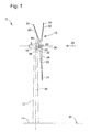
- Fig. 1 is a perspective view of an exemplary wind turbine 10.
- wind turbine 10 is a horizontal-axis wind turbine.
- wind turbine 10 may be a vertical-axis wind turbine.
- wind turbine 10 includes a tower 12 that extends from a support system 14, a nacelle 16 mounted on tower 12, and a rotor 18 that is coupled to nacelle 16.
- Rotor 18 includes a rotatable hub 20 and at least one rotor blade 22 coupled to and extending outward from hub 20.
- rotor 18 has three rotor blades 22.
- rotor 18 includes more or less than three rotor blades 22.
- tower 12 is fabricated from tubular steel to define a cavity (not shown in Fig. 1 ) between support system 14 and nacelle 16.
- tower 12 is any suitable type of tower having any suitable height.
- Rotor blades 22 are spaced about hub 20 to facilitate rotating rotor 18 to enable kinetic energy to be transferred from the wind into usable mechanical energy, and subsequently, electrical energy.
- Rotor blades 22 are mated to hub 20 by coupling a blade root portion 24 to hub 20 at a plurality of load transfer regions 26.
- Load transfer regions 26 have a hub load transfer region and a blade load transfer region (both not shown in Fig. 1 ). Loads induced to rotor blades 22 are transferred to hub 20 via load transfer regions 26.
- rotor blades 22 have a length ranging from about 15 meters (m) to about 91 m.
- rotor blades 22 may have any suitable length that enables wind turbine 10 to function as described herein.
- other nonlimiting examples of blade lengths include 10 m or less, 20 m, 37 m, or a length that is greater than 91 m.
- rotor 18 is rotated about an axis of rotation 30.
- rotor blades 22 are also subjected to various forces and moments. As such, rotor blades 22 may deflect and/or rotate from a neutral, or non-deflected, position to a deflected position.
- a pitch angle or blade pitch of rotor blades 22, i.e., an angle that determines a perspective of rotor blades 22 with respect to direction 28 of the wind, may be changed by a pitch adjustment system 32 to control the load and power generated by wind turbine 10 by adjusting an angular position of at least one rotor blade 22 relative to wind vectors.
- Pitch axes 34 for rotor blades 22 are shown.
- pitch adjustment system 32 may change a blade pitch of rotor blades 22 such that rotor blades 22 are moved to a feathered position, such that the perspective of at least one rotor blade 22 relative to wind vectors provides a minimal surface area of rotor blade 22 to be oriented towards the wind vectors, which facilitates reducing a rotational speed of rotor 18 and/or facilitates a stall of rotor 18.
- a blade pitch of each rotor blade 22 is controlled individually by a control system 36.
- the blade pitch for all rotor blades 22 may be controlled simultaneously by control system 36.
- a yaw direction of nacelle 16 may be controlled about a yaw axis 38 to position rotor blades 22 with respect to direction 28.
- control system 36 is shown as being centralized within nacelle 16, however, control system 36 may be a distributed system throughout wind turbine 10, on support system 14, within a wind farm, and/or at a remote control center.
- Control system 36 includes a processor 40 configured to perform the methods and/or steps described herein. Further, many of the other components described herein include a processor.
- processor is not limited to integrated circuits referred to in the art as a computer, but broadly refers to a control system, a microcontrol system, a microcomputer, a programmable logic control system (PLC), an application specific integrated circuit, and other programmable circuits, and these terms are used interchangeably herein. It should be understood that a processor and/or a control system can also include memory, input channels, and/or output channels.
- memory may include, without limitation, a computer-readable medium, such as a random access memory (RAM), and a computer-readable non-volatile medium, such as flash memory.
- RAM random access memory
- flash memory Alternatively, a floppy disk, a compact disc-read only memory (CD-ROM), a magneto-optical disk (MOD), and/or a digital versatile disc (DVD) may also be used.
- input channels include, without limitation, sensors and/or computer peripherals associated with an operator interface, such as a mouse and a keyboard.
- output channels may include, without limitation, a control device, an operator interface monitor and/or a display.
- Processors described herein process information transmitted from a plurality of electrical and electronic devices that may include, without limitation, sensors, actuators, compressors, control systems, and/or monitoring devices. Such processors may be physically located in, for example, a control system, a sensor, a monitoring device, a desktop computer, a laptop computer, a programmable logic control system (PLC) cabinet, and/or a distributed control system (DCS) cabinet.
- RAM and storage devices store and transfer information and instructions to be executed by the processor(s).
- RAM and storage devices can also be used to store and provide temporary variables, static (i.e., non-changing) information and instructions, or other intermediate information to the processors during execution of instructions by the processor(s). Instructions that are executed may include, without limitation, wind turbine control system control commands. The execution of sequences of instructions is not limited to any specific combination of hardware circuitry and software instructions.
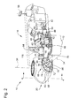
- Fig. 2 is an enlarged sectional view of a portion of wind turbine 10.
- wind turbine 10 includes nacelle 16 and hub 20 that is rotatably coupled to nacelle 16. More specifically, hub 20 is rotatably coupled to an electric generator 42 positioned within nacelle 16 by rotor shaft 44 (sometimes referred to as either a main shaft or a low speed shaft), a gearbox 46, a high speed shaft 48, and a coupling 50.
- rotor shaft 44 is disposed coaxial to longitudinal axis 116. Rotation of rotor shaft 44 rotatably drives gearbox 46 that subsequently drives high speed shaft 48.
- High speed shaft 48 rotatably drives generator 42 with coupling 50 and rotation of high speed shaft 48 facilitates production of electrical power by generator 42.
- Gearbox 46 and generator 42 are supported by a support 52 and a support 54.
- gearbox 46 utilizes a dual path geometry to drive high speed shaft 48.
- rotor shaft 44 is coupled directly to generator 42 with coupling 50.
- Nacelle 16 also includes a yaw drive mechanism 56 that may be used to rotate nacelle 16 and hub 20 on yaw axis 38 (shown in Fig. 1 ) to control the perspective of rotor blades 22 with respect to direction 28 of the wind.
- Nacelle 16 also includes at least one meteorological mast 58 that includes a wind vane and/or an anemometer (neither shown in Fig. 2 ). According to aspects, mast 58 provides information to control system 36 that may include wind direction and/or wind speed.
- nacelle 16 also includes a main forward support bearing 60 and a main aft support bearing 62.
- Forward support bearing 60 and aft support bearing 62 facilitate radial support and alignment of rotor shaft 44.
- Forward support bearing 60 is coupled to rotor shaft 44 near hub 20.
- Aft support bearing 62 is positioned on rotor shaft 44 near gearbox 46 and/or generator 42.
- nacelle 16 includes any number of support bearings that enable wind turbine 10 to function as disclosed herein.
- Rotor shaft 44, generator 42, gearbox 46, high speed shaft 48, coupling 50, and any associated fastening, support, and/or securing device including, but not limited to, support 52 and/or support 54, and forward support bearing 60 and aft support bearing 62, are sometimes referred to as a drive train 64.
- hub 20 includes a pitch assembly 66.
- Pitch assembly 66 includes one or more pitch drive systems 68 and at least one sensor 70.
- Each pitch drive system 68 is coupled to a respective rotor blade 22 (shown in Fig. 1 ) for modulating the blade pitch of associated rotor blade 22 along pitch axis 34. Only one of three pitch drive systems 68 is shown in Fig. 2 .
- pitch assembly 66 includes at least one pitch bearing 72 coupled to hub 20 and to respective rotor blade 22 (shown in Fig. 1 ) for rotating respective rotor blade 22 about pitch axis 34.
- Pitch drive system 68 includes a pitch drive motor 74, pitch drive gearbox 76, and pitch drive pinion 78.
- Pitch drive motor 74 is coupled to pitch drive gearbox 76 such that pitch drive motor 74 imparts mechanical force to pitch drive gearbox 76.
- Pitch drive gearbox 76 is coupled to pitch drive pinion 78 such that pitch drive pinion 78 is rotated by pitch drive gearbox 76.
- Pitch bearing 72 is coupled to pitch drive pinion 78 such that the rotation of pitch drive pinion 78 causes rotation of pitch bearing 72. More specifically, in the exemplary embodiment, pitch drive pinion 78 is coupled to pitch bearing 72 such that rotation of pitch drive gearbox 76 rotates pitch bearing 72 and rotor blade 22 about pitch axis 34 to change the blade pitch of blade 22.
- Pitch drive system 68 is coupled to control system 36 for adjusting the blade pitch of rotor blade 22 upon receipt of one or more signals from control system 36.
- pitch drive motor 74 is any suitable motor driven by electrical power and/or a hydraulic system that enables pitch assembly 66 to function as described herein.
- pitch assembly 66 may include any suitable structure, configuration, arrangement, and/or components such as, but not limited to, hydraulic cylinders, springs, and/or servo-mechanisms.
- pitch assembly 66 may be driven by any suitable means such as, but not limited to, hydraulic fluid, and/or mechanical power, such as, but not limited to, induced spring forces and/or electromagnetic forces.
- pitch drive motor 74 is driven by energy extracted from a rotational inertia of hub 20 and/or a stored energy source (not shown) that supplies energy to components of wind turbine 10.
- the wind turbine includes a sound measurement device 95.
- the sound measurement device may be positioned at some distance from the tower 12, for instance, at a distance of at least 100 m, or at a distance of at least 200 m.
- the sound measurement device may be placed, for instance, downwind with respect to the standard wind direction.
- the wind turbine is not allowed to exceed a permissible sound level.
- the permissible sound level may vary dependent on the time of day or night, or dependent on the wind direction, the wind power etc.
- the permissible sound level is prescribed in national, regional or local regulations. The noise impact to people living in the neighborhood of the wind turbines shall be limited.
- the operating parameters of the wind turbine that are of interest for this purpose are particularly the pitch angle, the rotational speed of the rotor, the desired power and the torque.
- the generated sound level is measured.
- Sound level measurement is typically undertaken at a distance from the wind turbine, such as at a distance of hub height plus half of the rotor diameter away from the wind turbine. The distance is typically selected in dependence of the hub height, the rotor diameter and/or the rated power.
- Measuring the sound level typically includes directly the sound level, e.g., by means of a microphone, or indirectly determining the sound level, e.g., by calculating the sound level on the basis of a model to which data such as speed, pitch angle, atmospheric measurement, torque etc are typically inputted.
- the measured sound is transmitted to the control system of the wind turbine.
- the control system takes the feedback signal into account when determining the operating parameters of the wind turbine such as, but not limited to, the optimal speed set-points, the optimal pitch offsets, the desired power and/or the optimal torque.
- the benefit of the proposed scheme is an increase in the precision of control and thus an increase in the energy yielded under the sound power management control scheme in view of the given noise regulations.
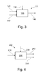
- sound model 111 consists of a function 100 that maps a pitch angle 120, a tip speed 110 and a wind speed 130 to an associated sound level 140. That is, the function 100 calculates how much noise the turbine would generate at any given pitch angle, tip speed, and wind speed.
- the function 100 may be a static function, i.e. described by algebraic equations, or a dynamic function, i.e., described by (partial) differential equations, recurrence equations, difference equations or state automata. In embodiments, it may be thus necessary to provide a memory for calculating the dynamic function.
- the function 100 may be used to calculate the associated sound level 140 based on the optimal pitch angle and tip speed for all possible wind speeds.
- the "optimal pitch angle” and the “optimal tip speed” are defined as the pitch and tip speed setting that maximize the power generated under given wind conditions and the permissible sound level.
- the function 100 is usually obtained by running a couple of offline numerical optimization problems under appropriate software.
- the function 100 is supposed to represent the real world, that is, the noise generated by a real world turbine if operated at the given parameters.
- the term "sound level” may particularly include the sound power level or the sound pressure.
- the sound level is directly measured by means of a sound measurement device, such as a microphone or the like. Alternatively it is possible to deduce the sound level by way of calculation from other measurements.
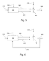
- the model 111 illustrated with respect to Fig. 3 can be used for defining an appropriate noise inverse map 222 illustrated with respect to Fig. 4 .
- the inverse function 200 defines a new function that outputs the respective settings such as the tip speed and pitch setting to be applied to a real wind turbine based on a desired level of sound.
- the desired maximal sound level 210 is inputted to the inverse function 200.
- the desired maximal sound level 210 is a function in dependence of the wind speed but could generally be dependent also on other variables.
- the inverse function 200 determines the corresponding pitch angle 240 and the rotor blade tip speed 220.
- the noise inverse function 200 as illustrated with respect to Fig. 4 is usually obtained by numerical methods based on the noise function 100 as exemplarily illustrated with respect to Fig. 3 .
- the conventional sound level control scheme is shown in Fig. 5 .
- the noise inverse function 200 calculates the corresponding wind turbine settings such as, but not limited to, the pitch angle 240 and tip speed 220. These values are used for the operation of the wind turbine 10.
- the wind turbine control thus adjusts the respective settings. For instance, it may pitch the blades.
- the turbine Given the operation under the settings 220 and 240 as well as under the given wind conditions, the turbine generates an amount of noise which is illustrated as the sound level 340 in Fig. 5 .
- the desired noise power level 210 and the sound level 340 emitted by the wind turbine should be identical. This is because the noise inverse function 200 should be, in theory, the function that is inverse to what sound level the wind turbine produces at a given wind speed.
- a feedback signal of the sound level is employed in order to reduce or eliminate the mismatch between the theoretical mapping and the real world situation.
- both the measured noise and a modeled noise are used for the control of the wind turbine.
- FIG. 6 A possible proposed scheme is shown in Fig. 6 .
- the sound level 340 is measured and fed back to a control system 36, which properly updates the operating parameters of the wind turbine with information such as the tip speed, torque, power and/or pitch setting.
- the feedback line 310 allows for the feeding back of the sound level 340 to the control system 36.
- the control system 36 is configured to calculate the noise inverse function, referred to by reference number 200 in the other figures.
- the control system may be configured to calculate a mismatch between the desired sound level 210 and the actual sound level 340. The mismatch is then considered when the turbine settings are calculated, such as the pitch angle 240 or the tip speed 220.
- the feedback line 310 is active only if the difference between the actually generated noise 340 and the desired sound level 210 is non-zero. Alternatively, in case there is no mismatch between the sound level 140 and the desired sound level 210, the feedback line 310 may send a signal corresponding to zero.
- L c refers to the re-defined sound level that is subsequently inputted to the inverse function 200 as basis for the calculation of corrected turbine settings.
- L d refers to the desired sound level which is referred to by reference number 210 in the figures.
- L m refers to the measured sound level which is referred to by reference number 340 in the figures.
- L M refers to the sound level according to the noise function that was referred to by reference number 100 previously. This sound level is referred to by reference number 140 in Fig. 3 .
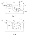
- Fig. 7 illustrates an embodiment for a method as described herein.
- the control system 36 receives the actual wind speed 230.
- the desired sound level 210 may be inputted to the control system 36, or, if a feedback signal is already available, the re-defined desired sound level 430. For instance, if there is no feedback signal available (maybe because the operation of the turbine has started shortly before or because there is no mismatch between the desired sound level and the actually generated sound level), the desired sound level 210 is equal to the re-defined sound level 430. However, in the case that there is a feedback signal, the re-defined sound level 430 is calculated as described, i.e.
- the redefinition factor 420 calculated as L m -L M , is subtracted from the desired sound level 210 thus yielding to the re-defined desired sound level 430.
- the re-defmition factor 420 corresponds to the parenthesis in the equation (1).
- a first subtractor 400 serves to subtract the re-defmition factor 420 from the desired sound level 210.
- the first subtractor 400 calculates L c according to equation (1).
- the first subtractor 400 is part of the control system 36 although, for clarity reasons, it is shown separately from the control system 36 in Fig. 7 .
- the control system is typically configured to calculate the corrected sound level L c .
- the control system is configured to calculate the corresponding turbine settings based on an inputted desired sound level.
- the control system does not calculate the wind turbine settings on the basis of the given desired sound level L d , referred to as number 210, but, instead, uses the corrected sound level L c , referred to as number 430 as a basis for the calculation of the wind turbine settings such as the pitch angle 240, the tip speed 220, the torque (omitted in the drawings in order to facilitate reading) or the like.
- the control system 36 thus bases its calculation of the turbine settings on an 'incorrect' desired sound level in the sense that this sound level is different from the desired s o und level L d .
- the concept of the present disclosure is not to use the feedback signal and the mismatch information thereof for an improvement of the underlying noise function but, instead, to accept that the theoretic noise function 200 does not perfectly match the real world and to avoid discrepancies nevertheless by feeding re-defmed desired sound levels to the calculation. These re-defmed sound levels differ from the actually desired sound level according to the theoretic noise inverse function 200.
- the re-defined sound level might even be higher than the actually allowed sound level. Nevertheless, given the discrepancies between the real world system 100 and the theoretic noise inverse function 200, this re-defined sound level might lead to turbine settings that exactly meet the allowed noise power level in practice.
- the feedback signal and the mismatch information associated therewith are used for improving the underlying noise function, in particular, to adjust the internal parameters of the model.
- the noise function may be adapted once there is a feedback signal indicating a mismatch in an iterative manner.
- the control system 36 calculates the corresponding wind turbine settings such as, but not limited to, the pitch angle 240 and the rotor blade tip speed 220. Based on this information, the wind turbine operates according to the respective wind turbine settings. Thereby, the wind turbine produces noise which is shown as the sound level 340.
- the calculated turbine settings such as the pitch angle 240 and the rotor blade tip speed 220 (as well as further parameters which were omitted for clarity reasons in the figures) are supplied to noise function 100 that maps the wind turbine settings, along with the wind speed 230, to the theoretically associated sound level 140 which was named L M in the previous equation (1).
- a second subtractor 440 is provided that subtracts the modeled sound level L M , referred to by reference number 140, from the measured sound level L m , referred to by reference number 340.
- the resulting correction factor L m -L M is then provided, directly or via the first subtractor 400, to the control system 36.
- the control system 36 is used for the subtraction of the modeled sound level L M , referred to by reference number 140, from the measured sound level L m , referred to by reference number 340 instead of a specific subtractor.
- Fig. 8 illustrates an embodiment wherein the complete calculation is done by one control system, that is, control system 36.
- the control system is the control system of the wind turbine.
- the control system receives the desired sound level L d , referred to by number 210, the measured sound level L m , referred to by number 340, and the modeled sound level L M , referred to by number 140.
- the sound level may refer, for instance, to a sound power level, a sound pressure level, or any other relevant noise measurement.
- the models can be static. According to other embodiments, the models can be dynamic.
- the control system calculates the corrected sound level L c and inputs it into the noise inverse function as explained with respect to previous figures.
- the outcome is turbine settings, such as, the pitch angle 240, the wind blade tip speed 220, torque settings (not shown) or other settings for operating the wind turbine.
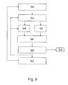
- Fig. 9 illustrates a method for operating a wind turbine according to embodiments described herein.
- a desired sound level L d is selected.
- the desired sound level L d can be selected by an operator, it may be retrieved from a database, or it may be retrieved from a processor outputting the desired sound level.
- some regulations prescribe reduced sound emission at night.
- the desired sound level might be adjusted according to the time of the day.
- the regulations may vary dependent on the seasons, the weather or the like.
- the desired sound level may be chosen in dependence of the wind speed and/or the ambient noise. For instance, for each value of the wind speed, a selected sound level should be achieved. According to embodiments, the desired sound level is a function of the ambient noise. For instance, if the ambient noise is high, the desired sound level may be selected high compared to a situation with low ambient noise. Hence, according to embodiments described herein, the wind turbine may further include a sound measurement device for measuring the ambient noise.
- the noise inverse function (referred to as reference number 200 in previous figures) is used to calculate the respective turbine settings for operating the turbine from the desired sound level L d , typically under consideration of the actual wind speed.
- the turbine settings particularly include the pitch angle, the tip speed, and the torque.
- the calculated turbine settings are used for operating the wind turbine.
- the calculated turbine settings are inputted to the noise function that has been referred to as reference number 100 in previous figures.
- the noise function therefrom calculates the theoretic sound level L M .
- the sound pressure level is calculated instead of the sound level and compared with the respective measured sound pressure level.
- the actual sound level L m is measured. Typically, a certain amount of time is waited between amending the wind turbine settings and measuring the generated noise in order to obtain a realistic measurement value referring to the operation at the desired settings, and not a measurement value relating to the transition time between the different operational modes.
- the measured sound level is compared to the desired sound level L d .
- the method it is possible to stop the method, that is, to proceed to block 570 which represents the end.
- the desired sound level L d has not changed, the method is continued with block 510, i.e. the calculation of the turbine settings, or with block 520, i.e. the measurement of the actual wind speed.
- the desired sound level L d is reset (for instance, because a specific time of the day is reached), it is possible to restart the method with block 500 again (this alternative is not shown in Fig. 9 ).
- a re-defined desired sound level L c is calculated in block 560.
- the calculation is performed as described previously and particularly with reference to equation (1).
- the re-defined sound level L c is used for the calculation of the subsequent wind turbine settings.
- the re-defined desired sound level L c is taken, and the method is repeated under this condition. This is shown in Fig. 9 wherein the connection from block 560 to block 500 shall indicate that the re-defined desired sound level is used as the new desired sound level.
- the method can be repeated as long as the desired wind power level is not identical to the measured sound level.
- the term "identical” in this sense shall include deviations of 3 % at maximum, typically of 1% or even 0.5% at minimum (in terms of decibel (db)). It is not shown in Fig. 9 , however, it is possible to stop the method, for instance, when wind conditions are such that the turbine has to be stopped, or in the event that the night is over and normal power optimized operation of the turbine is possible again.
- the calculation of the settings and the control of the turbine may be influenced by further circumstances such as the time of day, change in the wind (strength and direction), number of gusts etc. It is furthermore possible according to the embodiments described herein that the method is stopped if the wind speed is decreasing and thus leading to noise emissions that are clearly allowable under energy optimized control.
- the above-described systems and methods can facilitate and improve the control of one or more wind turbines under SPM. More specifically, they allow for better adherence to the regulations whilst improving the energy yield at the same time.
Abstract
Description
- The subject matter described herein relates generally to methods and systems for operating a wind turbine or a wind farm, and more particularly, to methods and systems for operating a wind turbine or a wind farm under noise management.
- At least some known wind turbines include a tower and a nacelle mounted on the tower. A rotor is rotatably mounted to the nacelle and is coupled to a generator by a shaft. A plurality of blades extend from the rotor. The blades are oriented such that wind passing over the blades turns the rotor and rotates the shaft, thereby driving the generator to generate electricity.
- During operation of such known wind turbines, rotational transiting of the blades through air generates aerodynamic acoustic emissions in the form of audible noise. These acoustic emissions may produce noise with a decibel (dB) level that may approach or even exceed local regulatory levels. Accordingly, at least some methods exist for controlling noise from a wind turbine or a wind turbine installation including a plurality of wind turbines (i.e., a wind farm). In particular, a wind turbine may be operated such that produced noise is below predetermined dB parameters. Such an operation of a wind turbine for reducing acoustic emissions is also known as noise reduction operation (NRO) or operation under sound power management (SPM).
- NRO typically implies that a wind turbine generates an electric power below the maximum possible power generation capacity of the wind turbine. Therefore, the operational state of a wind turbine under noise reduction operation is normally not directed to achieve a maximum power output but to comply with noise regulations applying to the wind turbine. However, during SPM, it is important to still yield the maximum amount of electric power that is possible under the prescribed regulations.
- In practice, however, it turns out that the operation under SPM does not always lead to the desired results. In some cases, the resulting generated power is below that of what could be expected given the allowed noise power level. In yet further situations, the resulting noise does still exceed the allowed level although it should not. Hence, it is a desire to improve the operation under SPM, in particular, it is a desire to increase the power output of a wind turbine or a wind farm operating under SPM. It is also particularly desirable that the noise regulations are met during operation under SPM.
- In one aspect according to the present invention, a method for operating a wind turbine is provided. The wind turbine generates a sound level. The method includes selecting a desired sound level; calculating at least one operating parameter by inputting the desired sound level to a model; and operating the wind turbine according to the at least one operating parameter. The method further includes measuring the sound level and based on the measured sound level, calculating at least one of a redefined desired sound level and a revised model. Furthermore, the method includes calculating at least one redefined operating parameter by at least one of inputting the redefined desired sound level to the model and inputting the desired sound level to the revised model.
- According to various aspects, the method is performed in the sequence described.
- In another aspect, a wind turbine is provided that includes a rotor with at least one rotor blade; a generator for converting kinetic energy supplied by the rotor into electric energy; and a control system for operating the wind turbine. The control system is configured to calculate at least one operating parameter by inputting a desired sound level to a model; operate the wind turbine according to the at least one operating parameter; obtain a measured sound level; based on the measured sound level, calculate at least one of a redefined desired sound level and a revised model; and calculate at least one redefined operating parameter for operating the wind turbine by one of inputting the redefined desired sound level to the model and inputting the desired sound level to the revised model.
- Various aspects, advantages and features of the present invention are apparent from the dependent claims, the description and the accompanying drawings, in which:
-
Fig. 1 is a perspective view of an exemplary wind turbine. -
Fig. 2 is an enlarged sectional view of a portion of the wind turbine shown inFig. 1 . -
Fig. 3 is a schematic diagram illustrating a noise map according to embodiments described herein. -
Fig. 4 is a schematic diagram illustrating a noise inverse map according to embodiments described herein. -
Fig. 5 is a schematic diagram illustrating the known operation of a wind turbine. -
Fig. 6 is a schematic diagram illustrating the operation of a wind turbine according to embodiments described herein. -
Fig. 7 is a schematic diagram illustrating the operation of a wind turbine according to embodiments described herein. -
Fig. 8 is a schematic diagram illustrating the operation of a wind turbine according to embodiments described herein. -
Fig. 9 is a schematic diagram illustrating the method for operating a wind turbine as described herein. - Reference will now be made in detail to the various embodiments, one or more examples of which are illustrated in each figure. Each example is provided by way of explanation and is not meant as a limitation. For example, features illustrated or described as part of one embodiment can be used on or in conjunction with other embodiments to yield yet further embodiments. It is intended that the present disclosure includes such modifications and variations.
- The embodiments described herein include a wind turbine that can be operated under sound power management in an improved manner. More specifically, the operation of the wind turbine allows for yielding a high energy output given the allowed sound level under SPM. In addition, the operation of the wind turbine allows particularly for achieving the prescribed sound level emission requirements.
- As used herein, the terms "sound power" and "noise" are used synonymously, and are intended to be representative of the overall acoustic emission of a wind turbine. Evidently, the sound power of a wind farm refers to the overall acoustic emission of a wind farm. As used herein, the term "blade" is intended to be representative of any device that provides a reactive force when in motion relative to a surrounding fluid. As used herein, the term "wind turbine" is intended to be representative of any device that generates rotational energy from wind energy, and more specifically, converts kinetic energy of wind into mechanical energy. As used herein, the term "wind generator" is intended to be representative of any wind turbine that generates electrical power from rotational energy generated from wind energy, and more specifically, converts mechanical energy converted from kinetic energy of wind to electrical power. The term "wind farm" refers to a plurality of wind turbines.
-
Fig. 1 is a perspective view of anexemplary wind turbine 10. In the exemplary embodiment,wind turbine 10 is a horizontal-axis wind turbine. Alternatively,wind turbine 10 may be a vertical-axis wind turbine. In the exemplary embodiment,wind turbine 10 includes atower 12 that extends from asupport system 14, anacelle 16 mounted ontower 12, and arotor 18 that is coupled tonacelle 16.Rotor 18 includes arotatable hub 20 and at least onerotor blade 22 coupled to and extending outward fromhub 20. In the exemplary embodiment,rotor 18 has threerotor blades 22. In an alternative embodiment,rotor 18 includes more or less than threerotor blades 22. In the exemplary embodiment,tower 12 is fabricated from tubular steel to define a cavity (not shown inFig. 1 ) betweensupport system 14 andnacelle 16. In an alternative embodiment,tower 12 is any suitable type of tower having any suitable height. -
Rotor blades 22 are spaced abouthub 20 to facilitate rotatingrotor 18 to enable kinetic energy to be transferred from the wind into usable mechanical energy, and subsequently, electrical energy.Rotor blades 22 are mated tohub 20 by coupling ablade root portion 24 tohub 20 at a plurality ofload transfer regions 26.Load transfer regions 26 have a hub load transfer region and a blade load transfer region (both not shown inFig. 1 ). Loads induced torotor blades 22 are transferred tohub 20 viaload transfer regions 26. - In one embodiment,
rotor blades 22 have a length ranging from about 15 meters (m) to about 91 m. Alternatively,rotor blades 22 may have any suitable length that enableswind turbine 10 to function as described herein. For example, other nonlimiting examples of blade lengths include 10 m or less, 20 m, 37 m, or a length that is greater than 91 m. As wind strikesrotor blades 22 from adirection 28,rotor 18 is rotated about an axis ofrotation 30. Asrotor blades 22 are rotated and subjected to centrifugal forces,rotor blades 22 are also subjected to various forces and moments. As such,rotor blades 22 may deflect and/or rotate from a neutral, or non-deflected, position to a deflected position. - Moreover, a pitch angle or blade pitch of
rotor blades 22, i.e., an angle that determines a perspective ofrotor blades 22 with respect todirection 28 of the wind, may be changed by apitch adjustment system 32 to control the load and power generated bywind turbine 10 by adjusting an angular position of at least onerotor blade 22 relative to wind vectors. Pitch axes 34 forrotor blades 22 are shown. During operation ofwind turbine 10,pitch adjustment system 32 may change a blade pitch ofrotor blades 22 such thatrotor blades 22 are moved to a feathered position, such that the perspective of at least onerotor blade 22 relative to wind vectors provides a minimal surface area ofrotor blade 22 to be oriented towards the wind vectors, which facilitates reducing a rotational speed ofrotor 18 and/or facilitates a stall ofrotor 18. - In the exemplary embodiment, a blade pitch of each
rotor blade 22 is controlled individually by acontrol system 36. Alternatively, the blade pitch for allrotor blades 22 may be controlled simultaneously bycontrol system 36. Further, in the exemplary embodiment, asdirection 28 changes, a yaw direction ofnacelle 16 may be controlled about ayaw axis 38 to positionrotor blades 22 with respect todirection 28. - In the exemplary embodiment,
control system 36 is shown as being centralized withinnacelle 16, however,control system 36 may be a distributed system throughoutwind turbine 10, onsupport system 14, within a wind farm, and/or at a remote control center.Control system 36 includes aprocessor 40 configured to perform the methods and/or steps described herein. Further, many of the other components described herein include a processor. As used herein, the term "processor" is not limited to integrated circuits referred to in the art as a computer, but broadly refers to a control system, a microcontrol system, a microcomputer, a programmable logic control system (PLC), an application specific integrated circuit, and other programmable circuits, and these terms are used interchangeably herein. It should be understood that a processor and/or a control system can also include memory, input channels, and/or output channels. - In the embodiments described herein, memory may include, without limitation, a computer-readable medium, such as a random access memory (RAM), and a computer-readable non-volatile medium, such as flash memory. Alternatively, a floppy disk, a compact disc-read only memory (CD-ROM), a magneto-optical disk (MOD), and/or a digital versatile disc (DVD) may also be used. Also, in the embodiments described herein, input channels include, without limitation, sensors and/or computer peripherals associated with an operator interface, such as a mouse and a keyboard. Further, in the exemplary embodiment, output channels may include, without limitation, a control device, an operator interface monitor and/or a display.
- Processors described herein process information transmitted from a plurality of electrical and electronic devices that may include, without limitation, sensors, actuators, compressors, control systems, and/or monitoring devices. Such processors may be physically located in, for example, a control system, a sensor, a monitoring device, a desktop computer, a laptop computer, a programmable logic control system (PLC) cabinet, and/or a distributed control system (DCS) cabinet. RAM and storage devices store and transfer information and instructions to be executed by the processor(s). RAM and storage devices can also be used to store and provide temporary variables, static (i.e., non-changing) information and instructions, or other intermediate information to the processors during execution of instructions by the processor(s). Instructions that are executed may include, without limitation, wind turbine control system control commands. The execution of sequences of instructions is not limited to any specific combination of hardware circuitry and software instructions.
-
Fig. 2 is an enlarged sectional view of a portion ofwind turbine 10. In the exemplary embodiment,wind turbine 10 includesnacelle 16 andhub 20 that is rotatably coupled tonacelle 16. More specifically,hub 20 is rotatably coupled to anelectric generator 42 positioned withinnacelle 16 by rotor shaft 44 (sometimes referred to as either a main shaft or a low speed shaft), agearbox 46, ahigh speed shaft 48, and acoupling 50. In the exemplary embodiment,rotor shaft 44 is disposed coaxial tolongitudinal axis 116. Rotation ofrotor shaft 44 rotatably drivesgearbox 46 that subsequently driveshigh speed shaft 48.High speed shaft 48 rotatably drivesgenerator 42 withcoupling 50 and rotation ofhigh speed shaft 48 facilitates production of electrical power bygenerator 42.Gearbox 46 andgenerator 42 are supported by asupport 52 and asupport 54. In the exemplary embodiment,gearbox 46 utilizes a dual path geometry to drivehigh speed shaft 48. Alternatively,rotor shaft 44 is coupled directly togenerator 42 withcoupling 50. -
Nacelle 16 also includes ayaw drive mechanism 56 that may be used to rotatenacelle 16 andhub 20 on yaw axis 38 (shown inFig. 1 ) to control the perspective ofrotor blades 22 with respect todirection 28 of the wind.Nacelle 16 also includes at least onemeteorological mast 58 that includes a wind vane and/or an anemometer (neither shown inFig. 2 ). According to aspects,mast 58 provides information to controlsystem 36 that may include wind direction and/or wind speed. In the exemplary embodiment,nacelle 16 also includes a main forward support bearing 60 and a mainaft support bearing 62. - Forward support bearing 60 and aft support bearing 62 facilitate radial support and alignment of
rotor shaft 44. Forward support bearing 60 is coupled torotor shaft 44 nearhub 20. Aft support bearing 62 is positioned onrotor shaft 44 neargearbox 46 and/orgenerator 42. Alternatively,nacelle 16 includes any number of support bearings that enablewind turbine 10 to function as disclosed herein.Rotor shaft 44,generator 42,gearbox 46,high speed shaft 48,coupling 50, and any associated fastening, support, and/or securing device including, but not limited to, support 52 and/orsupport 54, and forward support bearing 60 and aft support bearing 62, are sometimes referred to as adrive train 64. - In the exemplary embodiment,
hub 20 includes apitch assembly 66.Pitch assembly 66 includes one or morepitch drive systems 68 and at least onesensor 70. Eachpitch drive system 68 is coupled to a respective rotor blade 22 (shown inFig. 1 ) for modulating the blade pitch of associatedrotor blade 22 alongpitch axis 34. Only one of threepitch drive systems 68 is shown inFig. 2 . - In the exemplary embodiment,
pitch assembly 66 includes at least one pitch bearing 72 coupled tohub 20 and to respective rotor blade 22 (shown inFig. 1 ) for rotatingrespective rotor blade 22 aboutpitch axis 34.Pitch drive system 68 includes apitch drive motor 74,pitch drive gearbox 76, andpitch drive pinion 78.Pitch drive motor 74 is coupled to pitchdrive gearbox 76 such thatpitch drive motor 74 imparts mechanical force to pitchdrive gearbox 76.Pitch drive gearbox 76 is coupled to pitchdrive pinion 78 such thatpitch drive pinion 78 is rotated bypitch drive gearbox 76.Pitch bearing 72 is coupled to pitchdrive pinion 78 such that the rotation ofpitch drive pinion 78 causes rotation ofpitch bearing 72. More specifically, in the exemplary embodiment,pitch drive pinion 78 is coupled to pitch bearing 72 such that rotation ofpitch drive gearbox 76 rotates pitch bearing 72 androtor blade 22 aboutpitch axis 34 to change the blade pitch ofblade 22. -
Pitch drive system 68 is coupled to controlsystem 36 for adjusting the blade pitch ofrotor blade 22 upon receipt of one or more signals fromcontrol system 36. In the exemplary embodiment,pitch drive motor 74 is any suitable motor driven by electrical power and/or a hydraulic system that enablespitch assembly 66 to function as described herein. Alternatively,pitch assembly 66 may include any suitable structure, configuration, arrangement, and/or components such as, but not limited to, hydraulic cylinders, springs, and/or servo-mechanisms. Moreover,pitch assembly 66 may be driven by any suitable means such as, but not limited to, hydraulic fluid, and/or mechanical power, such as, but not limited to, induced spring forces and/or electromagnetic forces. In certain embodiments,pitch drive motor 74 is driven by energy extracted from a rotational inertia ofhub 20 and/or a stored energy source (not shown) that supplies energy to components ofwind turbine 10. - According to various aspects described herein, the wind turbine includes a
sound measurement device 95. The sound measurement device may be positioned at some distance from thetower 12, for instance, at a distance of at least 100 m, or at a distance of at least 200 m. The sound measurement device may be placed, for instance, downwind with respect to the standard wind direction. Generally, under sound power management control, the wind turbine is not allowed to exceed a permissible sound level. The permissible sound level may vary dependent on the time of day or night, or dependent on the wind direction, the wind power etc. Typically, the permissible sound level is prescribed in national, regional or local regulations. The noise impact to people living in the neighborhood of the wind turbines shall be limited. - Despite the limited allowance to operate the wind turbine at full power, it is desirable to yield the maximum amount of energy given the allowed sound level. That is, in view of the allowed power level it is desirable to find the operating parameters of the wind turbine that allow the maximum power output. The operating parameters of the wind turbine that are of interest for this purpose are particularly the pitch angle, the rotational speed of the rotor, the desired power and the torque.
- According to various aspects described herein, the generated sound level is measured. Sound level measurement is typically undertaken at a distance from the wind turbine, such as at a distance of hub height plus half of the rotor diameter away from the wind turbine. The distance is typically selected in dependence of the hub height, the rotor diameter and/or the rated power. However, it is also possible to measure the sound level at the wind turbine which might allow for conclusions on the sound distribution in the vicinity of the wind turbine. Measuring the sound level typically includes directly the sound level, e.g., by means of a microphone, or indirectly determining the sound level, e.g., by calculating the sound level on the basis of a model to which data such as speed, pitch angle, atmospheric measurement, torque etc are typically inputted.
- The measured sound is transmitted to the control system of the wind turbine. The control system takes the feedback signal into account when determining the operating parameters of the wind turbine such as, but not limited to, the optimal speed set-points, the optimal pitch offsets, the desired power and/or the optimal torque.
- The benefit of the proposed scheme is an increase in the precision of control and thus an increase in the energy yielded under the sound power management control scheme in view of the given noise regulations.
- The sound level model shall be explained with respect to the following figures. To start with, as illustrated in
Fig. 3 ,sound model 111 consists of afunction 100 that maps apitch angle 120, atip speed 110 and awind speed 130 to an associatedsound level 140. That is, thefunction 100 calculates how much noise the turbine would generate at any given pitch angle, tip speed, and wind speed. Generally, and not limited to this embodiment, thefunction 100 may be a static function, i.e. described by algebraic equations, or a dynamic function, i.e., described by (partial) differential equations, recurrence equations, difference equations or state automata. In embodiments, it may be thus necessary to provide a memory for calculating the dynamic function. - In particular, the
function 100 may be used to calculate the associatedsound level 140 based on the optimal pitch angle and tip speed for all possible wind speeds. The "optimal pitch angle" and the "optimal tip speed" are defined as the pitch and tip speed setting that maximize the power generated under given wind conditions and the permissible sound level. Thefunction 100 is usually obtained by running a couple of offline numerical optimization problems under appropriate software. Thefunction 100 is supposed to represent the real world, that is, the noise generated by a real world turbine if operated at the given parameters. - Generally, and not limited to the present embodiment, the term "sound level" may particularly include the sound power level or the sound pressure. Typically, the sound level is directly measured by means of a sound measurement device, such as a microphone or the like. Alternatively it is possible to deduce the sound level by way of calculation from other measurements.
- The
model 111 illustrated with respect toFig. 3 can be used for defining an appropriate noiseinverse map 222 illustrated with respect toFig. 4 . Theinverse function 200 defines a new function that outputs the respective settings such as the tip speed and pitch setting to be applied to a real wind turbine based on a desired level of sound. In more detail, as exemplarily illustrated in the figure, the desiredmaximal sound level 210 is inputted to theinverse function 200. In the embodiment illustrated, the desiredmaximal sound level 210 is a function in dependence of the wind speed but could generally be dependent also on other variables. Given the measuredwind speed 230, theinverse function 200 determines thecorresponding pitch angle 240 and the rotorblade tip speed 220. - The noise
inverse function 200 as illustrated with respect toFig. 4 is usually obtained by numerical methods based on thenoise function 100 as exemplarily illustrated with respect toFig. 3 . - The conventional sound level control scheme is shown in
Fig. 5 . Given a desiredsound level 210 and a givenwind speed 230, the noiseinverse function 200 calculates the corresponding wind turbine settings such as, but not limited to, thepitch angle 240 andtip speed 220. These values are used for the operation of thewind turbine 10. The wind turbine control thus adjusts the respective settings. For instance, it may pitch the blades. - Given the operation under the
settings sound level 340 inFig. 5 . - In theory, the desired
noise power level 210 and thesound level 340 emitted by the wind turbine should be identical. This is because the noiseinverse function 200 should be, in theory, the function that is inverse to what sound level the wind turbine produces at a given wind speed. - However, experience shows that, in practice, there are differences between the desired
sound level 210 and the emittedsound level 340. There can be several reasons for this. One reason can be that the computer model and the real system do not match exactly. That is, thenoise function 100 and consequently the noiseinverse function 200 do not fully comply with the reality. For instance, the theoretical calculation of the emitted sound level is 5% below what the real sound emission level is. In this case, the turbine is operated with prohibited noise emissions. Another reason can be that the wind speed is not measured with the necessary accuracy, that is, thewind speed level 230 as illustrated in the present figures does not fully match the real wind speed. - Hence, as a result of these obstacles, in practice there is a mismatch between the desired sound level and the factual emitted sound level is persistent. This mismatch can have various negative effects. For instance, the wind turbine could operate at a lower efficiency level than the one corresponding to the desired sound level. This causes commercial disadvantage. Another effect could be that the actual sound level exceeds the desired and permissible sound level, which causes undue sound annoyance for the neighbors. Furthermore, in case of a repeated excess of the permissible sound level, the wind turbine operator might be forced to drastically reduce the operation or even shut down the wind turbine.
- Hence, in order to address those issues, according to aspects described herein, a feedback signal of the sound level is employed in order to reduce or eliminate the mismatch between the theoretical mapping and the real world situation. According to embodiments, both the measured noise and a modeled noise are used for the control of the wind turbine.
- A possible proposed scheme is shown in
Fig. 6 . Thesound level 340 is measured and fed back to acontrol system 36, which properly updates the operating parameters of the wind turbine with information such as the tip speed, torque, power and/or pitch setting. As illustrated inFig. 6 , thefeedback line 310 allows for the feeding back of thesound level 340 to thecontrol system 36. Thecontrol system 36 is configured to calculate the noise inverse function, referred to byreference number 200 in the other figures. In addition, the control system may be configured to calculate a mismatch between the desiredsound level 210 and theactual sound level 340. The mismatch is then considered when the turbine settings are calculated, such as thepitch angle 240 or thetip speed 220. - According to various embodiments, the
feedback line 310 is active only if the difference between the actually generatednoise 340 and the desiredsound level 210 is non-zero. Alternatively, in case there is no mismatch between thesound level 140 and the desiredsound level 210, thefeedback line 310 may send a signal corresponding to zero. - In the following, it shall exemplarily be explained in more detail how the feedback is performed. In case there is a mismatch between the desired
sound level 210 and theactual sound level 340, thecontrol system 36 re-defines the desiredsound level 210 as follows:
- In this equation (1), Lc refers to the re-defined sound level that is subsequently inputted to the
inverse function 200 as basis for the calculation of corrected turbine settings. Ld refers to the desired sound level which is referred to byreference number 210 in the figures. Lm refers to the measured sound level which is referred to byreference number 340 in the figures. LM refers to the sound level according to the noise function that was referred to byreference number 100 previously. This sound level is referred to byreference number 140 inFig. 3 . -
Fig. 7 illustrates an embodiment for a method as described herein. Thecontrol system 36 receives theactual wind speed 230. In addition, the desiredsound level 210 may be inputted to thecontrol system 36, or, if a feedback signal is already available, the re-defined desiredsound level 430. For instance, if there is no feedback signal available (maybe because the operation of the turbine has started shortly before or because there is no mismatch between the desired sound level and the actually generated sound level), the desiredsound level 210 is equal to there-defined sound level 430. However, in the case that there is a feedback signal, there-defined sound level 430 is calculated as described, i.e. theredefinition factor 420, calculated as Lm-LM, is subtracted from the desiredsound level 210 thus yielding to the re-defined desiredsound level 430. There-defmition factor 420 corresponds to the parenthesis in the equation (1). - In
Fig. 7 , afirst subtractor 400 serves to subtract there-defmition factor 420 from the desiredsound level 210. In other words, thefirst subtractor 400 calculates Lc according to equation (1). - According to typical embodiments, the
first subtractor 400 is part of thecontrol system 36 although, for clarity reasons, it is shown separately from thecontrol system 36 inFig. 7 . Thus, the control system is typically configured to calculate the corrected sound level Lc. In addition, the control system is configured to calculate the corresponding turbine settings based on an inputted desired sound level. - According to various aspects described herein, at least when there is a feedback signal, the control system does not calculate the wind turbine settings on the basis of the given desired sound level Ld, referred to as
number 210, but, instead, uses the corrected sound level Lc, referred to asnumber 430 as a basis for the calculation of the wind turbine settings such as thepitch angle 240, thetip speed 220, the torque (omitted in the drawings in order to facilitate reading) or the like. - The
control system 36 thus bases its calculation of the turbine settings on an 'incorrect' desired sound level in the sense that this sound level is different from the desired sound level Ld. In other words, according to an aspect, the concept of the present disclosure is not to use the feedback signal and the mismatch information thereof for an improvement of the underlying noise function but, instead, to accept that thetheoretic noise function 200 does not perfectly match the real world and to avoid discrepancies nevertheless by feeding re-defmed desired sound levels to the calculation. These re-defmed sound levels differ from the actually desired sound level according to the theoretic noiseinverse function 200. - For instance, in theory, that is according to the noise
inverse function 200, the re-defined sound level might even be higher than the actually allowed sound level. Nevertheless, given the discrepancies between thereal world system 100 and the theoretic noiseinverse function 200, this re-defined sound level might lead to turbine settings that exactly meet the allowed noise power level in practice. - According to another aspect of the present disclosure, the feedback signal and the mismatch information associated therewith are used for improving the underlying noise function, in particular, to adjust the internal parameters of the model. For instance, the noise function may be adapted once there is a feedback signal indicating a mismatch in an iterative manner.
- The
control system 36 calculates the corresponding wind turbine settings such as, but not limited to, thepitch angle 240 and the rotorblade tip speed 220. Based on this information, the wind turbine operates according to the respective wind turbine settings. Thereby, the wind turbine produces noise which is shown as thesound level 340. - In addition, the calculated turbine settings such as the
pitch angle 240 and the rotor blade tip speed 220 (as well as further parameters which were omitted for clarity reasons in the figures) are supplied tonoise function 100 that maps the wind turbine settings, along with thewind speed 230, to the theoretically associatedsound level 140 which was named LM in the previous equation (1). - According to the embodiment shown in
Fig. 7 , asecond subtractor 440 is provided that subtracts the modeled sound level LM, referred to byreference number 140, from the measured sound level Lm, referred to byreference number 340. As set forth previously, the resulting correction factor Lm-LM, referred to byreference number 420 inFig. 7 , is then provided, directly or via thefirst subtractor 400, to thecontrol system 36. According to other embodiments, thecontrol system 36 is used for the subtraction of the modeled sound level LM, referred to byreference number 140, from the measured sound level Lm, referred to byreference number 340 instead of a specific subtractor. -
Fig. 8 illustrates an embodiment wherein the complete calculation is done by one control system, that is,control system 36. Typically, the control system is the control system of the wind turbine. The control system receives the desired sound level Ld, referred to bynumber 210, the measured sound level Lm, referred to bynumber 340, and the modeled sound level LM, referred to bynumber 140. The sound level may refer, for instance, to a sound power level, a sound pressure level, or any other relevant noise measurement. Generally, and not limited to the present embodiment, the models can be static. According to other embodiments, the models can be dynamic. - The control system calculates the corrected sound level Lc and inputs it into the noise inverse function as explained with respect to previous figures. The outcome is turbine settings, such as, the
pitch angle 240, the windblade tip speed 220, torque settings (not shown) or other settings for operating the wind turbine. -
Fig. 9 illustrates a method for operating a wind turbine according to embodiments described herein. Inblock 500, a desired sound level Ld is selected. For instance, and not limited to the present embodiment but applicable to all embodiments described herein, the desired sound level Ld can be selected by an operator, it may be retrieved from a database, or it may be retrieved from a processor outputting the desired sound level. For instance, some regulations prescribe reduced sound emission at night. Hence, the desired sound level might be adjusted according to the time of the day. Also, the regulations may vary dependent on the seasons, the weather or the like. - The desired sound level may be chosen in dependence of the wind speed and/or the ambient noise. For instance, for each value of the wind speed, a selected sound level should be achieved. According to embodiments, the desired sound level is a function of the ambient noise. For instance, if the ambient noise is high, the desired sound level may be selected high compared to a situation with low ambient noise. Hence, according to embodiments described herein, the wind turbine may further include a sound measurement device for measuring the ambient noise.
- According to the
next block 510, the noise inverse function (referred to asreference number 200 in previous figures) is used to calculate the respective turbine settings for operating the turbine from the desired sound level Ld, typically under consideration of the actual wind speed. The turbine settings particularly include the pitch angle, the tip speed, and the torque. - According to the
next block 520, the calculated turbine settings are used for operating the wind turbine. Possibly, but not necessarily at the same time, according to block 530, the calculated turbine settings are inputted to the noise function that has been referred to asreference number 100 in previous figures. The noise function therefrom calculates the theoretic sound level LM. According to embodiments, the sound pressure level is calculated instead of the sound level and compared with the respective measured sound pressure level. - According to block 540, the actual sound level Lm is measured. Typically, a certain amount of time is waited between amending the wind turbine settings and measuring the generated noise in order to obtain a realistic measurement value referring to the operation at the desired settings, and not a measurement value relating to the transition time between the different operational modes.
- According to block 550, the measured sound level is compared to the desired sound level Ld. In the event that they are identical, no changes need to be made to the settings. Hence, it is possible to stop the method, that is, to proceed to block 570 which represents the end. Alternatively, it is possible to wait for a selected amount of time, such as between 1 and 100 minutes, typically between 10 and 50 minutes, depending on the turbine and the application, before restarting the procedure again. For instance, if the desired sound level Ld has not changed, the method is continued with
block 510, i.e. the calculation of the turbine settings, or withblock 520, i.e. the measurement of the actual wind speed. In those cases where the desired sound level Ld is reset (for instance, because a specific time of the day is reached), it is possible to restart the method withblock 500 again (this alternative is not shown inFig. 9 ). - In case there is a mismatch between the desired sound level Ld and the measured sound level Lm, a re-defined desired sound level Lc is calculated in
block 560. The calculation is performed as described previously and particularly with reference to equation (1). The re-defined sound level Lc is used for the calculation of the subsequent wind turbine settings. Thus, instead of taking the desired sound level Ld as basis for the calculation of the wind turbine settings, the re-defined desired sound level Lc is taken, and the method is repeated under this condition. This is shown inFig. 9 wherein the connection fromblock 560 to block 500 shall indicate that the re-defined desired sound level is used as the new desired sound level. - The method can be repeated as long as the desired wind power level is not identical to the measured sound level. The term "identical" in this sense shall include deviations of 3 % at maximum, typically of 1% or even 0.5% at minimum (in terms of decibel (db)). It is not shown in
Fig. 9 , however, it is possible to stop the method, for instance, when wind conditions are such that the turbine has to be stopped, or in the event that the night is over and normal power optimized operation of the turbine is possible again. Generally, and not limited to this embodiment, the calculation of the settings and the control of the turbine may be influenced by further circumstances such as the time of day, change in the wind (strength and direction), number of gusts etc. It is furthermore possible according to the embodiments described herein that the method is stopped if the wind speed is decreasing and thus leading to noise emissions that are clearly allowable under energy optimized control. - The above-described systems and methods can facilitate and improve the control of one or more wind turbines under SPM. More specifically, they allow for better adherence to the regulations whilst improving the energy yield at the same time.
- Exemplary embodiments of systems and methods for one or more wind turbines are described above in detail. The systems and methods are not limited to the specific embodiments described herein, but rather, components of the systems and/or steps of the methods may be utilized independently and separately from other components and/or steps described herein. Although specific features of various embodiments of the invention may be shown in some drawings and not in others, this is for convenience only. In accordance with the principles of the invention, any feature of a drawing may be referenced and/or claimed in combination with any feature of any other drawing.
- This written description uses examples to disclose the invention (including the preferred mode) and also to enable any person skilled in the art to practice the invention, including making and using any devices or systems and performing any incorporated methods. While various specific embodiments have been disclosed in the foregoing, those skilled in the art will recognize that the spirit and scope of the claims allows for equally effective modifications. Especially, mutually non-exclusive features of the embodiments described above may be combined with each other. The patentable scope of the invention is defined by the claims, and may include other examples that occur to those skilled in the art. Such other examples are intended to be within the scope of the claims if they have structural elements that do not differ from the literal language of the claims, or if they include equivalent structural elements with insubstantial differences from the literal language of the claims.
- Various aspects and embodiments of the present invention are defined by the following numbered clauses:
- 1. A method for operating a wind turbine, wherein the wind turbine generates a sound level, the method comprising:
- a) selecting a desired sound level;
- b) calculating at least one operating parameter by inputting the desired sound level to a model;
- c) operating the wind turbine according to the at least one operating parameter;
- d) measuring the sound level;
- e) based on the measured sound level, calculating at least one of a redefined desired sound level and a revised model; and,
- f) calculating at least one redefined operating parameter by at least one of inputting the redefined desired sound level to the model and inputting the desired sound level to the revised model.
- 2. The method for operating the wind turbine according to clause 1, wherein
- a) calculating at least one of the redefined desired sound level and the revised model consists of calculating the redefined desired sound level; and,
- b) calculating at least one redefined operating parameter is done by inputting the redefined desired sound level to the model.
- 3. The method according to any preceding clause, wherein the redefined desired sound level is allowed to be above the desired sound level.
- 4. The method according to any preceding clause, wherein the desired sound level corresponds to the sound level prescribed by wind turbine operation regulations.
- 5. The method for operating a wind turbine according to any preceding clause, wherein the redefined sound level is calculated as the desired sound level minus a sound level redefinition factor.
- 6. The method for operating a wind turbine according to any preceding clause, wherein the sound level redefinition factor is calculated as the measured sound level minus a modeled sound level.
- 7. The method for operating a wind turbine according to any preceding clause, further comprising operating the wind turbine according to the redefined operating parameter.
- 8. The method for operating a wind turbine according to any preceding clause, wherein the method is performed as a loop.
- 9. The method for operating a wind turbine according to any preceding clause, wherein the loop is performed continuously.
- 10. The method for operating a wind turbine according to any preceding clause, wherein the oop is repeated in selected time intervals.
- 11. The method for operating a wind turbine according to any preceding clause, wherein the desired sound power level is selected in dependence of at least one of the daytime, the wind direction, and the wind speed.
- 12. The method for operating a wind turbine according to any preceding clause, wherein at least one of the operating parameter for operating the wind turbine and the redefined operating parameter for operating the wind turbine are selected from a pitch angle, a blade tip speed, a torque, and a power.
- 13. The method for operating a wind turbine according to any preceding clause, the method further comprising comparing the desired sound level with the measured sound level.
- 14. The method for operating a wind turbine according to any preceding clause, wherein calculating at least one of a redefined desired sound level and a revised model is not undertaken if the desired sound level is identical to the measured sound level.
- 15. A wind turbine, comprising:
- a) a rotor including at least one rotor blade;
- b) a generator for converting kinetic energy supplied by the rotor into electric energy; and,
- c) a control system for operating the wind turbine, the control system being configured to:
- i) calculate at least one operating parameter by inputting a desired sound level to a model;
- ii) operate the wind turbine according to the at leaset one operating parameter;
- iii) obtain a measured sound level;
- iv) based on the measured sound level, calculate at least one of a redefined desired sound level and a revised model; and,
- v) calculate at least one redefined operating parameter for operating the wind turbine by one of inputting the redefined desired sound level to the model and inputting the desired sound level to the revised model.
- 16. The wind turbine according to any preceding clause, wherein the control system is configured to adapt at least one of a torque of the generator and a pitch angle of the at least one rotor blade.
- 17. The wind turbine according to any preceding clause, further comprising a mast for providing at least one of a wind direction and a wind speed to the control system.
- 18. The wind turbine according to any preceding clause, wherein
- a) calculating at least one of a redefmed desired sound level and a revised model consists of calculating the redefined desired sound level; and,
- b) calculating at least one redefined operating parameter is done by inputting the redefined desired sound level to the model.
- 19. The wind turbine according to any preceding clause, further comprising a sound measurement device.
- 20. The wind turbine according to any preceding clause, further comprising a tower wherein the sound measurement device is positioned at a distance of at least 100 m from the tower.
Claims (15)
- A method (500) for operating a wind turbine (10), wherein the wind turbine generates a sound level (140), the method comprising:a) selecting a desired sound level (210);b) calculating at least one operating parameter by inputting the desired sound (210) level to a model;c) operating the wind turbine (10) according to the at least one operating parameter;d) measuring the sound level (140);e) based on the measured sound level (340), calculating at least one of a redefined desired sound level and a revised model; andf) calculating at least one redefined operating parameter by at least one of inputting the redefined desired sound level to the model and inputting the desired sound level to the revised model.
- The method (500) for operating the wind turbine (10) according to claim 1, whereina) calculating at least one of the redefined desired sound level and the revised model consists of calculating the redefined desired sound level; andb) calculating at least one redefined operating parameter is done by inputting the redefined desired sound level to the model.
- The method (500) according to any of the preceding claims, wherein the redefined desired sound level is allowed to be above the desired sound level.
- The method (500) according to any of the preceding claims, wherein the desired sound level corresponds to the sound level prescribed by wind turbine operation regulations.
- The method (500) for operating a wind turbine (10) according to any of the preceding claims, wherein the redefined sound level is calculated as the desired sound level minus a sound level redefinition factor, wherein the sound level redefinition factor is optionally calculated as the measured sound level minus a modeled sound level.
- The method (500) for operating a wind turbine (10) according to any of the preceding claims, further comprising operating the wind turbine (10) according to the redefined operating parameter.
- The method (500) for operating a wind turbine (10) according to any of the preceding claims, wherein the method is performed as a loop, that is optionally performed continuously, and the loop is optionally repeated in selected time intervals.
- The method (500) for operating a wind turbine (10) according to any of the preceding claims, wherein the desired sound power level is selected in dependence of at least one of the daytime, the wind direction, and the wind speed.
- The method (500) for operating a wind turbine (10) according to any of the preceding claims, wherein at least one of the operating parameter for operating the wind turbine (10) and the redefined operating parameter for operating the wind turbine are selected from a pitch angle, a blade tip speed, a torque, and a power.
- The method (500) for operating a wind turbine (10) according to any of the preceding claims, the method further comprising comparing the desired sound level with the measured sound level, and, optionally, calculating at least one of a redefined desired sound level and a revised model is not undertaken if the desired sound level is identical to the measured sound level.
- A wind turbine (10), comprising:a) a rotor (18) including at least one rotor blade (22);b) a generator (42) for converting kinetic energy supplied by the rotor into electric energy; andc) a control system (36) for operating the wind turbine, the control system being configured to:i) calculate at least one operating parameter by inputting a desired sound level to a model;ii) operate the wind turbine according to the at least one operating parameter;iii) obtain a measured sound level;iv) based on the measured sound level, calculate at least one of a redefined desired sound level and a revised model; andv) calculate at least one redefined operating parameter for operating the wind turbine by one of inputting the redefined desired sound level to the model and inputting the desired sound level to the revised model.
- The wind turbine (10) according to claim 11, wherein the control system (36) is configured to adapt at least one of a torque of the generator and a pitch angle of the at least one rotor blade (22).
- The wind turbine (10) according to claim 11 or 12, further comprising a metereological mast (58) for providing at least one of a wind direction and a wind speed to the control system.
- The wind turbine (10) according to any of claims 11 to 13, whereina) calculating at least one of a redefined desired sound level and a revised model consists of calculating the redefined desired sound level; andb) calculating at least one redefined operating parameter is done by inputting the redefined desired sound level to the model.
- The wind turbine (10) according to any of claims 11 to 14, further comprising a sound measurement device and a tower (12), wherein the sound measurement device (95) is optionally positioned at a distance of at least 100 m from the tower.
Applications Claiming Priority (1)
| Application Number | Priority Date | Filing Date | Title |
|---|---|---|---|
| US13/235,348 US8304926B2 (en) | 2011-09-16 | 2011-09-16 | Wind turbine sound management |
Publications (2)
| Publication Number | Publication Date |
|---|---|
| EP2570657A1 true EP2570657A1 (en) | 2013-03-20 |
| EP2570657B1 EP2570657B1 (en) | 2016-06-29 |
Family
ID=46161508
Family Applications (1)
| Application Number | Title | Priority Date | Filing Date |
|---|---|---|---|
| EP12183567.2A Active EP2570657B1 (en) | 2011-09-16 | 2012-09-07 | Wind turbine sound management |
Country Status (3)
| Country | Link |
|---|---|
| US (1) | US8304926B2 (en) |
| EP (1) | EP2570657B1 (en) |
| CN (1) | CN102996334B (en) |
Cited By (1)
| Publication number | Priority date | Publication date | Assignee | Title |
|---|---|---|---|---|
| DE102016107230A1 (en) * | 2016-04-19 | 2017-10-19 | Wobben Properties Gmbh | Wind turbine and method for controlling a wind turbine |
Families Citing this family (10)
| Publication number | Priority date | Publication date | Assignee | Title |
|---|---|---|---|---|
| US9014861B2 (en) * | 2011-12-20 | 2015-04-21 | General Electric Company | Method and system for noise-controlled operation of a wind turbine |
| CA2898915C (en) * | 2014-07-31 | 2022-10-25 | General Electric Company | System and method for optimal operation of wind farms |
| US9347432B2 (en) | 2014-07-31 | 2016-05-24 | General Electric Company | System and method for enhanced operation of wind parks |
| CN106569175A (en) * | 2016-10-13 | 2017-04-19 | 成都格瑞思文化传播有限公司 | IoT based wind field patrol car positioning system |
| EP3551879B1 (en) * | 2016-12-09 | 2020-10-28 | Vestas Wind Systems A/S | Adaptive noise control for wind turbine |
| CN107387319A (en) * | 2017-09-06 | 2017-11-24 | 合肥凌山新能源科技有限公司 | A kind of wind-force intelligent control system based on wind power generation |
| CN110500234B (en) * | 2018-05-18 | 2020-07-03 | 北京金风科创风电设备有限公司 | Method and device for noise control of wind generating set |
| CN110500233B (en) * | 2018-05-18 | 2020-07-07 | 北京金风科创风电设备有限公司 | Method and device for noise control of a plurality of wind energy installations |
| EP3605249A1 (en) * | 2018-08-02 | 2020-02-05 | Siemens Aktiengesellschaft | Method for synchronizing, method for operating an industrial installation, system, and computer readable medium and computer program product |
| US11462204B2 (en) * | 2020-09-08 | 2022-10-04 | Siemens Gamesa Renewable Energy A/S | Wind turbine and method for noise reduction for a wind turbine |
Citations (3)
| Publication number | Priority date | Publication date | Assignee | Title |
|---|---|---|---|---|
| US20100143119A1 (en) * | 2009-09-30 | 2010-06-10 | Kooijman Hendrikus J T | Method and apparatus for controlling acoustic emissions of a wind turbine |
| US20100158687A1 (en) * | 2008-12-19 | 2010-06-24 | Frontier Wind, Llc | Control Modes for Extendable Rotor Blades |
| US20110223006A1 (en) * | 2010-12-06 | 2011-09-15 | Friedrich Loh | System, device, and method for noise-based operation of wind turbines |
Family Cites Families (12)
| Publication number | Priority date | Publication date | Assignee | Title |
|---|---|---|---|---|
| PT1141543E (en) * | 1998-12-09 | 2005-02-28 | Wobben Aloys | SOUND REDUCTION OF A ROTOR PTO FOR AN EOL TURBINE |
| EP1192355B2 (en) * | 1999-06-10 | 2015-10-21 | Aloys Wobben | Wind energy system with adjustment of the sound level |
| ES2261100B1 (en) * | 2006-03-29 | 2007-08-01 | Gamesa Corporacion Tecnologica, S.A. | ANTI-NOISE AEROGENERATOR. |
| US8021110B2 (en) | 2007-01-05 | 2011-09-20 | General Electric Company | Tonal emission control for wind turbines |
| WO2010037387A2 (en) * | 2008-09-30 | 2010-04-08 | Vestas Wind Systems A/S | Control of wind park noise emission |
| WO2010061255A2 (en) | 2008-11-01 | 2010-06-03 | Clipper Windpower, Inc. | Active blade pitch control for reduction of wind turbine noise or loads |
| US20100135798A1 (en) | 2009-02-10 | 2010-06-03 | General Electric Company | Wind turbine noise controls |
| US7763989B2 (en) | 2009-07-07 | 2010-07-27 | General Electric Company | Method and apparatus for controlling the tip speed of a blade of a wind turbine |
| US7945350B2 (en) | 2009-07-07 | 2011-05-17 | General Electric Company | Wind turbine acoustic emission control system and method |
| US7902689B2 (en) | 2009-07-07 | 2011-03-08 | General Electric Company | Method and system for noise controlled operation of a wind turbine |
| US8414261B2 (en) | 2011-05-31 | 2013-04-09 | General Electric Company | Noise reducer for rotor blade in wind turbine |
| US8232663B2 (en) * | 2011-06-30 | 2012-07-31 | General Electric Company | Controlling noise generated by wind turbines in a wind farm by de-synchronization of wind turbine rotors |
-
2011
- 2011-09-16 US US13/235,348 patent/US8304926B2/en active Active
-
2012
- 2012-09-07 EP EP12183567.2A patent/EP2570657B1/en active Active
- 2012-09-14 CN CN201210342251.9A patent/CN102996334B/en not_active Expired - Fee Related
Patent Citations (3)
| Publication number | Priority date | Publication date | Assignee | Title |
|---|---|---|---|---|
| US20100158687A1 (en) * | 2008-12-19 | 2010-06-24 | Frontier Wind, Llc | Control Modes for Extendable Rotor Blades |
| US20100143119A1 (en) * | 2009-09-30 | 2010-06-10 | Kooijman Hendrikus J T | Method and apparatus for controlling acoustic emissions of a wind turbine |
| US20110223006A1 (en) * | 2010-12-06 | 2011-09-15 | Friedrich Loh | System, device, and method for noise-based operation of wind turbines |
Cited By (1)
| Publication number | Priority date | Publication date | Assignee | Title |
|---|---|---|---|---|
| DE102016107230A1 (en) * | 2016-04-19 | 2017-10-19 | Wobben Properties Gmbh | Wind turbine and method for controlling a wind turbine |
Also Published As
| Publication number | Publication date |
|---|---|
| US20120139254A1 (en) | 2012-06-07 |
| US8304926B2 (en) | 2012-11-06 |
| CN102996334A (en) | 2013-03-27 |
| EP2570657B1 (en) | 2016-06-29 |
| CN102996334B (en) | 2016-12-21 |
Similar Documents
| Publication | Publication Date | Title |
|---|---|---|
| EP2570657B1 (en) | Wind turbine sound management | |
| US7772713B2 (en) | Method and system for controlling a wind turbine | |
| DK178157B1 (en) | Device and method for operating a wind turbine | |
| AU2011253697B2 (en) | Methods and systems for determining a pitch angle offset signal and for controlling a rotor frequency of a rotor of a wind turbine for speed avoidance control | |
| US7945350B2 (en) | Wind turbine acoustic emission control system and method | |
| US8303251B2 (en) | Systems and methods for assembling a pitch assembly for use in a wind turbine | |
| US9163611B2 (en) | Methods and systems for operating a wind turbine coupled to a power grid | |
| EP2306004A2 (en) | Method and apparatus for controlling acoustic emissions of a wind turbine | |
| EP2581600A2 (en) | Method and system for control of wind turbines | |
| US20120027589A1 (en) | Method and apparatus for control of asymmetric loading of a wind turbine | |
| EP2264311A2 (en) | Wind turbine comprising an active flow control device on the rotor blade | |
| EP2657518A2 (en) | Methods and systems for operating a wind turbine in noise reduced operation modes | |
| US11242841B2 (en) | System and method for controlling a wind turbine based on a collective pitch-offset | |
| US11608811B2 (en) | System and method for mitigating loads acting on a rotor blade of a wind turbine | |
| US11536247B2 (en) | System and method for improved extreme load control for wind turbine components | |
| EP4194689A1 (en) | System and method for controlling blade pitch of wind turbine rotor blades in an idling state of the rotor hub | |
| US20230175487A1 (en) | System and method for controlling blade pitch on wind turbine rotor blades to reduce vibrations and limit loads in a locked condition of the turbine rotor | |
| EP3964706A1 (en) | A method for operating a wind turbine, a method for designing a wind turbine, and a wind turbine | |
| EP3699421A1 (en) | Method of dynamically adjusting a rate of change of a rotor speed set point during wind turbine shutdown | |
| US11668280B2 (en) | Yaw systems and methods |
Legal Events
| Date | Code | Title | Description |
|---|---|---|---|
| PUAI | Public reference made under article 153(3) epc to a published international application that has entered the european phase |
Free format text: ORIGINAL CODE: 0009012 |
|
| AK | Designated contracting states |
Kind code of ref document: A1 Designated state(s): AL AT BE BG CH CY CZ DE DK EE ES FI FR GB GR HR HU IE IS IT LI LT LU LV MC MK MT NL NO PL PT RO RS SE SI SK SM TR |
|
| AX | Request for extension of the european patent |
Extension state: BA ME |
|
| 17P | Request for examination filed |
Effective date: 20130920 |
|
| RBV | Designated contracting states (corrected) |
Designated state(s): AL AT BE BG CH CY CZ DE DK EE ES FI FR GB GR HR HU IE IS IT LI LT LU LV MC MK MT NL NO PL PT RO RS SE SI SK SM TR |
|
| 17Q | First examination report despatched |
Effective date: 20141223 |
|
| GRAP | Despatch of communication of intention to grant a patent |
Free format text: ORIGINAL CODE: EPIDOSNIGR1 |
|
| INTG | Intention to grant announced |
Effective date: 20160323 |
|
| INTG | Intention to grant announced |
Effective date: 20160330 |
|
| RIC1 | Information provided on ipc code assigned before grant |
Ipc: F03D 80/00 20160101ALI20160318BHEP Ipc: F03D 7/02 20060101AFI20160318BHEP |
|
| GRAS | Grant fee paid |
Free format text: ORIGINAL CODE: EPIDOSNIGR3 |
|
| GRAA | (expected) grant |
Free format text: ORIGINAL CODE: 0009210 |
|
| AK | Designated contracting states |
Kind code of ref document: B1 Designated state(s): AL AT BE BG CH CY CZ DE DK EE ES FI FR GB GR HR HU IE IS IT LI LT LU LV MC MK MT NL NO PL PT RO RS SE SI SK SM TR |
|
| REG | Reference to a national code |
Ref country code: GB Ref legal event code: FG4D |
|
| REG | Reference to a national code |
Ref country code: CH Ref legal event code: EP |
|
| REG | Reference to a national code |
Ref country code: AT Ref legal event code: REF Ref document number: 809319 Country of ref document: AT Kind code of ref document: T Effective date: 20160715 |
|
| REG | Reference to a national code |
Ref country code: IE Ref legal event code: FG4D |
|
| REG | Reference to a national code |
Ref country code: DK Ref legal event code: T3 Effective date: 20160801 |
|
| REG | Reference to a national code |
Ref country code: DE Ref legal event code: R096 Ref document number: 602012019912 Country of ref document: DE |
|
| REG | Reference to a national code |
Ref country code: FR Ref legal event code: PLFP Year of fee payment: 5 |
|
| REG | Reference to a national code |
Ref country code: LT Ref legal event code: MG4D |
|
| PG25 | Lapsed in a contracting state [announced via postgrant information from national office to epo] |
Ref country code: NO Free format text: LAPSE BECAUSE OF FAILURE TO SUBMIT A TRANSLATION OF THE DESCRIPTION OR TO PAY THE FEE WITHIN THE PRESCRIBED TIME-LIMIT Effective date: 20160929 Ref country code: FI Free format text: LAPSE BECAUSE OF FAILURE TO SUBMIT A TRANSLATION OF THE DESCRIPTION OR TO PAY THE FEE WITHIN THE PRESCRIBED TIME-LIMIT Effective date: 20160629 Ref country code: LT Free format text: LAPSE BECAUSE OF FAILURE TO SUBMIT A TRANSLATION OF THE DESCRIPTION OR TO PAY THE FEE WITHIN THE PRESCRIBED TIME-LIMIT Effective date: 20160629 |
|
| REG | Reference to a national code |
Ref country code: NL Ref legal event code: MP Effective date: 20160629 |
|
| PG25 | Lapsed in a contracting state [announced via postgrant information from national office to epo] |
Ref country code: RS Free format text: LAPSE BECAUSE OF FAILURE TO SUBMIT A TRANSLATION OF THE DESCRIPTION OR TO PAY THE FEE WITHIN THE PRESCRIBED TIME-LIMIT Effective date: 20160629 Ref country code: HR Free format text: LAPSE BECAUSE OF FAILURE TO SUBMIT A TRANSLATION OF THE DESCRIPTION OR TO PAY THE FEE WITHIN THE PRESCRIBED TIME-LIMIT Effective date: 20160629 Ref country code: LV Free format text: LAPSE BECAUSE OF FAILURE TO SUBMIT A TRANSLATION OF THE DESCRIPTION OR TO PAY THE FEE WITHIN THE PRESCRIBED TIME-LIMIT Effective date: 20160629 Ref country code: GR Free format text: LAPSE BECAUSE OF FAILURE TO SUBMIT A TRANSLATION OF THE DESCRIPTION OR TO PAY THE FEE WITHIN THE PRESCRIBED TIME-LIMIT Effective date: 20160930 Ref country code: SE Free format text: LAPSE BECAUSE OF FAILURE TO SUBMIT A TRANSLATION OF THE DESCRIPTION OR TO PAY THE FEE WITHIN THE PRESCRIBED TIME-LIMIT Effective date: 20160629 Ref country code: NL Free format text: LAPSE BECAUSE OF FAILURE TO SUBMIT A TRANSLATION OF THE DESCRIPTION OR TO PAY THE FEE WITHIN THE PRESCRIBED TIME-LIMIT Effective date: 20160629 |
|
| REG | Reference to a national code |
Ref country code: AT Ref legal event code: MK05 Ref document number: 809319 Country of ref document: AT Kind code of ref document: T Effective date: 20160629 |
|
| PG25 | Lapsed in a contracting state [announced via postgrant information from national office to epo] |
Ref country code: IS Free format text: LAPSE BECAUSE OF FAILURE TO SUBMIT A TRANSLATION OF THE DESCRIPTION OR TO PAY THE FEE WITHIN THE PRESCRIBED TIME-LIMIT Effective date: 20161029 Ref country code: RO Free format text: LAPSE BECAUSE OF FAILURE TO SUBMIT A TRANSLATION OF THE DESCRIPTION OR TO PAY THE FEE WITHIN THE PRESCRIBED TIME-LIMIT Effective date: 20160629 Ref country code: IT Free format text: LAPSE BECAUSE OF FAILURE TO SUBMIT A TRANSLATION OF THE DESCRIPTION OR TO PAY THE FEE WITHIN THE PRESCRIBED TIME-LIMIT Effective date: 20160629 Ref country code: CZ Free format text: LAPSE BECAUSE OF FAILURE TO SUBMIT A TRANSLATION OF THE DESCRIPTION OR TO PAY THE FEE WITHIN THE PRESCRIBED TIME-LIMIT Effective date: 20160629 Ref country code: SK Free format text: LAPSE BECAUSE OF FAILURE TO SUBMIT A TRANSLATION OF THE DESCRIPTION OR TO PAY THE FEE WITHIN THE PRESCRIBED TIME-LIMIT Effective date: 20160629 Ref country code: EE Free format text: LAPSE BECAUSE OF FAILURE TO SUBMIT A TRANSLATION OF THE DESCRIPTION OR TO PAY THE FEE WITHIN THE PRESCRIBED TIME-LIMIT Effective date: 20160629 |
|
| PG25 | Lapsed in a contracting state [announced via postgrant information from national office to epo] |
Ref country code: PT Free format text: LAPSE BECAUSE OF FAILURE TO SUBMIT A TRANSLATION OF THE DESCRIPTION OR TO PAY THE FEE WITHIN THE PRESCRIBED TIME-LIMIT Effective date: 20161031 Ref country code: ES Free format text: LAPSE BECAUSE OF FAILURE TO SUBMIT A TRANSLATION OF THE DESCRIPTION OR TO PAY THE FEE WITHIN THE PRESCRIBED TIME-LIMIT Effective date: 20160629 Ref country code: SM Free format text: LAPSE BECAUSE OF FAILURE TO SUBMIT A TRANSLATION OF THE DESCRIPTION OR TO PAY THE FEE WITHIN THE PRESCRIBED TIME-LIMIT Effective date: 20160629 Ref country code: PL Free format text: LAPSE BECAUSE OF FAILURE TO SUBMIT A TRANSLATION OF THE DESCRIPTION OR TO PAY THE FEE WITHIN THE PRESCRIBED TIME-LIMIT Effective date: 20160629 Ref country code: BE Free format text: LAPSE BECAUSE OF NON-PAYMENT OF DUE FEES Effective date: 20160629 Ref country code: AT Free format text: LAPSE BECAUSE OF FAILURE TO SUBMIT A TRANSLATION OF THE DESCRIPTION OR TO PAY THE FEE WITHIN THE PRESCRIBED TIME-LIMIT Effective date: 20160629 |
|
| REG | Reference to a national code |
Ref country code: DE Ref legal event code: R097 Ref document number: 602012019912 Country of ref document: DE |
|
| PG25 | Lapsed in a contracting state [announced via postgrant information from national office to epo] |
Ref country code: MC Free format text: LAPSE BECAUSE OF FAILURE TO SUBMIT A TRANSLATION OF THE DESCRIPTION OR TO PAY THE FEE WITHIN THE PRESCRIBED TIME-LIMIT Effective date: 20160629 |
|
| REG | Reference to a national code |
Ref country code: CH Ref legal event code: PL |
|
| PLBE | No opposition filed within time limit |
Free format text: ORIGINAL CODE: 0009261 |
|
| STAA | Information on the status of an ep patent application or granted ep patent |
Free format text: STATUS: NO OPPOSITION FILED WITHIN TIME LIMIT |
|
| GBPC | Gb: european patent ceased through non-payment of renewal fee |
Effective date: 20160929 |
|
| 26N | No opposition filed |
Effective date: 20170330 |
|
| STAA | Information on the status of an ep patent application or granted ep patent |
Free format text: STATUS: NO OPPOSITION FILED WITHIN TIME LIMIT |
|
| PG25 | Lapsed in a contracting state [announced via postgrant information from national office to epo] |
Ref country code: LI Free format text: LAPSE BECAUSE OF NON-PAYMENT OF DUE FEES Effective date: 20160930 Ref country code: CH Free format text: LAPSE BECAUSE OF NON-PAYMENT OF DUE FEES Effective date: 20160930 Ref country code: GB Free format text: LAPSE BECAUSE OF NON-PAYMENT OF DUE FEES Effective date: 20160929 |
|
| PG25 | Lapsed in a contracting state [announced via postgrant information from national office to epo] |
Ref country code: LU Free format text: LAPSE BECAUSE OF NON-PAYMENT OF DUE FEES Effective date: 20160907 Ref country code: BG Free format text: LAPSE BECAUSE OF FAILURE TO SUBMIT A TRANSLATION OF THE DESCRIPTION OR TO PAY THE FEE WITHIN THE PRESCRIBED TIME-LIMIT Effective date: 20160929 Ref country code: SI Free format text: LAPSE BECAUSE OF FAILURE TO SUBMIT A TRANSLATION OF THE DESCRIPTION OR TO PAY THE FEE WITHIN THE PRESCRIBED TIME-LIMIT Effective date: 20160629 |
|
| REG | Reference to a national code |
Ref country code: FR Ref legal event code: PLFP Year of fee payment: 6 |
|
| PG25 | Lapsed in a contracting state [announced via postgrant information from national office to epo] |
Ref country code: CY Free format text: LAPSE BECAUSE OF FAILURE TO SUBMIT A TRANSLATION OF THE DESCRIPTION OR TO PAY THE FEE WITHIN THE PRESCRIBED TIME-LIMIT Effective date: 20160629 Ref country code: HU Free format text: LAPSE BECAUSE OF FAILURE TO SUBMIT A TRANSLATION OF THE DESCRIPTION OR TO PAY THE FEE WITHIN THE PRESCRIBED TIME-LIMIT; INVALID AB INITIO Effective date: 20120907 |
|
| PG25 | Lapsed in a contracting state [announced via postgrant information from national office to epo] |
Ref country code: MT Free format text: LAPSE BECAUSE OF NON-PAYMENT OF DUE FEES Effective date: 20160930 Ref country code: TR Free format text: LAPSE BECAUSE OF FAILURE TO SUBMIT A TRANSLATION OF THE DESCRIPTION OR TO PAY THE FEE WITHIN THE PRESCRIBED TIME-LIMIT Effective date: 20160629 Ref country code: MK Free format text: LAPSE BECAUSE OF FAILURE TO SUBMIT A TRANSLATION OF THE DESCRIPTION OR TO PAY THE FEE WITHIN THE PRESCRIBED TIME-LIMIT Effective date: 20160629 |
|
| REG | Reference to a national code |
Ref country code: FR Ref legal event code: PLFP Year of fee payment: 7 |
|
| PG25 | Lapsed in a contracting state [announced via postgrant information from national office to epo] |
Ref country code: AL Free format text: LAPSE BECAUSE OF FAILURE TO SUBMIT A TRANSLATION OF THE DESCRIPTION OR TO PAY THE FEE WITHIN THE PRESCRIBED TIME-LIMIT Effective date: 20160629 |
|
| PGFP | Annual fee paid to national office [announced via postgrant information from national office to epo] |
Ref country code: IE Payment date: 20180911 Year of fee payment: 12 |
|
| PG25 | Lapsed in a contracting state [announced via postgrant information from national office to epo] |
Ref country code: IE Free format text: LAPSE BECAUSE OF NON-PAYMENT OF DUE FEES Effective date: 20190907 |
|
| P01 | Opt-out of the competence of the unified patent court (upc) registered |
Effective date: 20230530 |
|
| PGFP | Annual fee paid to national office [announced via postgrant information from national office to epo] |
Ref country code: FR Payment date: 20230822 Year of fee payment: 12 Ref country code: DK Payment date: 20230822 Year of fee payment: 12 Ref country code: DE Payment date: 20230822 Year of fee payment: 12 |
|
| REG | Reference to a national code |
Ref country code: DE Ref legal event code: R081 Ref document number: 602012019912 Country of ref document: DE Owner name: GENERAL ELECTRIC RENOVABLES ESPANA, S.L., ES Free format text: FORMER OWNER: GENERAL ELECTRIC COMPANY, SCHENECTADY, NY, US |