EP2552322B1 - Tissue excision device - Google Patents
Tissue excision device Download PDFInfo
- Publication number
- EP2552322B1 EP2552322B1 EP11713575.6A EP11713575A EP2552322B1 EP 2552322 B1 EP2552322 B1 EP 2552322B1 EP 11713575 A EP11713575 A EP 11713575A EP 2552322 B1 EP2552322 B1 EP 2552322B1
- Authority
- EP
- European Patent Office
- Prior art keywords
- blade
- cannula
- coring cannula
- stylet
- coring
- Prior art date
- Legal status (The legal status is an assumption and is not a legal conclusion. Google has not performed a legal analysis and makes no representation as to the accuracy of the status listed.)
- Not-in-force
Links
Images


Classifications
-
- A—HUMAN NECESSITIES
- A61—MEDICAL OR VETERINARY SCIENCE; HYGIENE
- A61B—DIAGNOSIS; SURGERY; IDENTIFICATION
- A61B10/00—Other methods or instruments for diagnosis, e.g. instruments for taking a cell sample, for biopsy, for vaccination diagnosis; Sex determination; Ovulation-period determination; Throat striking implements
- A61B10/02—Instruments for taking cell samples or for biopsy
- A61B10/0233—Pointed or sharp biopsy instruments
- A61B10/0266—Pointed or sharp biopsy instruments means for severing sample
-
- A—HUMAN NECESSITIES
- A61—MEDICAL OR VETERINARY SCIENCE; HYGIENE
- A61B—DIAGNOSIS; SURGERY; IDENTIFICATION
- A61B10/00—Other methods or instruments for diagnosis, e.g. instruments for taking a cell sample, for biopsy, for vaccination diagnosis; Sex determination; Ovulation-period determination; Throat striking implements
- A61B10/02—Instruments for taking cell samples or for biopsy
- A61B2010/0225—Instruments for taking cell samples or for biopsy for taking multiple samples
-
- A—HUMAN NECESSITIES
- A61—MEDICAL OR VETERINARY SCIENCE; HYGIENE
- A61B—DIAGNOSIS; SURGERY; IDENTIFICATION
- A61B90/00—Instruments, implements or accessories specially adapted for surgery or diagnosis and not covered by any of the groups A61B1/00 - A61B50/00, e.g. for luxation treatment or for protecting wound edges
- A61B90/06—Measuring instruments not otherwise provided for
- A61B2090/062—Measuring instruments not otherwise provided for penetration depth
Definitions
- the present invention relates generally to surgical instruments, and more particularly, to a device for percutaneous excision of tissue, percutaneous excisional breast biopsy or percutaneous incisional breast biopsy.
- the biopsy device includes a localization needle with a guide wire preloaded into the device.
- the localization needle and guide wire are used to locate and localize the target area.
- the methodology of their usage can be summarized as follows:
- the device can either by a handheld device or may be a fixed device.
- the below more detailed description of the method of using a prior art device is described with respect to a handheld device.
- a localization needle is placed at the center of the target tissue.
- a localization wire is used to fix the handheld device to the tissue.
- a stylet is manually advanced to a point just proximal of the target.
- the cannula is manually advanced over the target tissue. With the cannula advanced over the target tissue, a mechanism, such as a garrote wire is activated to sever the target tissue from the breast. With the target tissue severed from the breast, the device, along with the target tissue with the cannula, may be removed.
- a mechanism such as a garrote wire is activated to sever the target tissue from the breast.
- these prior art devices are purely mechanical devices, i.e., in other words, the coring cannula is advanced by hand.
- the surgeon or user rotates a knob that activates a gear system to rotate and advances the coring cannula.
- the start/stop motion can increase patient discomfort, as well as produce an undesirable irregular specimen shape.
- a garrote wire may be used to cut the sample tissue (which is inside the cannula) from the breast so that it may be removed.
- the garrote wire has several limitations. Typically, the garrote wire traverse (at least partially) along the length of the device, then is bent at a 90 degree angle, after which it encircles an inner surface of the coring cannula. The right angle in the garrote wire results in requiring a large amount of force to pull on the garrote wire to transect the tissue sample. Additionally, the garrote wire is generally located a distance behind the cutting edge of the coring cannula.
- the garrote wire may tear the tissue rather than cutting the tissue. Additionally, dense tissue can be pushed aside rather than cut.
- Another issue related to prior art designs is the size of the cutting edge of the cannula with respect to the stylet.
- a skin incision is made using a scalpel. This incision is generally just slightly wider than the diameter of the cannula.
- the stylet is advanced in the breast, up to the point where the coring blade is ready to enter the incision.
- the surgeon will use nerve hooks to grab the skin and open the incision to allow the cutting edge of the cannula to enter the breast.
- the process of using the nerve hooks to grab the skin to make the incision wider can be cumbersome and inefficient and can cause patient discomfort.
- the current devices use a stylet with integral cutting blades.
- the flat stylet blades are fixed to the stylet which may result in several adverse conditions.
- the close proximity of the cutting edge of the stylet blades to the ramp or stylet tip results in the pushing or compression or other inadvertent movement of the tissue by the stylet.
- the prior designs also results in a fixed minimal proximal margin equal to the length of the stylet system.
- the present invention is aimed at one or more of the problems identified above.
- the invention is defined in claim 1.
- Preferred embodiments are defined in dependent claims 2-12.
- a biopsy device according to the preamble of claim 1 is disclosed in US-A-4 461 305 .
- a biopsy device includes a housing, a coring cannula, and a flexible transection blade.
- the coring cannula has a longitudinal axis and is coupled to the housing.
- the coring cannula is rotatable about the axis.
- These flexible transection blade has a first end and a second end and is coupled to the coring cannula at the first end, the second end forming a cutting edge, the flexible transection blade having a first blade position and a second blade position, wherein rotation of the coring cannula in a first direction moves the flexible transection blade from the first blade position to the second blade position.
- the biopsy device includes a housing, a coring cannula, and a flexible transection blade.
- the coring cannula has a longitudinal axis and is centered on the axis and is coupled to the housing.
- the coring cannula is rotatable about the axis.
- the flexible transection blade has a first end and a second end and is coupled to the coring cannula, the second end forming a cutting edge, the flexible transection blade having a first blade position and a second blade position.
- the invention is characterized in that the coring cannula is movable along the axis from an initial cannula location towards a final cannula location in response to rotation of the coring cannula about the axis in a first direction, the flexible transection blade is in the first blade position while the coring cannula is between the initial and final cannula locations, wherein rotation of the coring cannula in the first direction while the coring cannula is at the final cannula location rotates the flexible transection blade about the axis, moving the flexible transection blade from the first blade position to the second blade position, where the flexible transection blade is at least partly contained within the coring cannula when the coring cannula is between the initial position and the final position, wherein motion of the flexible transection blade from the first blade position to the second blade position advances the transection blade past the coring cannula.
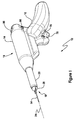
- the present invention provides a breast biopsy device 10 and a method of operating the breast biopsy device 10.
- the breast biopsy device 10 is embodied in a handheld device 12. It should be noted that the present invention may be embodied in a fixed device (not shown).
- the handheld device 12 may include a housing 14 (see Figure 10 ) and a handle 16.
- the housing 14 is removable from the handle 16.
- the handle 16 is reusable.
- the housing 14 (and all parts contained therein) are disposable and generally provided sterile.
- the device 10 may include an integrated needle assembly 18 (described below).
- the device 10 may include an independent needle assembly 18' (described below).
- the housing 14 may include an inner passage 22 (see Figure 10 ).
- a coring cannula 20 is slidably mounted within the inner passage 22 of the housing 14.
- the coring cannula 20 has a longitudinal axis 24 and may include a shaft 26 centered on the axis 24.
- the coring cannula 20 is coupled to the housing such that rotational movement of the coring cannula 20 about the axis 24 results in linear movement of the coring cannula 20 along the axis 24.
- the coring cannula 20 has a cutting edge allowing it to cut through tissue as it is rotated and advanced.
- the coring cannula 20 may simply rotate within the housing 14 .
- Linear movement of the coring cannula 20 may be provided by external mechanical means or by the user.
- the breast biopsy device 10 includes a stylet 28 , which includes a stylet housing 38.
- the stylet includes a tip 30 .
- the tip 30 includes at least one blade 32 and a central passage 34 .
- the tip 30 may also include a slot 31 for the at least one blade 32 .
- the stylet 28 is mounted within the coring cannula 20 .
- the stylet 28 includes first and second blades 32A, 32B integrated between two half portions 38A, 38B of a stylet housing 38 .
- the stylet 28 transects, dilates, and separates tissue as the device 10 is inserted or advanced towards the biopsy site.
- a drive assembly 40 mounted within the housing 14 and the handle 16 rotates the cannula 20 and controllably rotates the cannula 20 .
- the drive assembly 40 also moves the cannula 20 in a direction parallel to (and along) the axis 24 .
- the coring cannula 20 has a predetermined linear advancement per revolution of the coring cannula 20 .
- the predetermined linear advancement is 1.27 cm (0.50 inches) per revolution.
- the predetermined linear advancement is 2.13 cm (0.84) inches per revolution.
- the drive assembly 40 may include a motor assembly comprised of a DC motor and step down transmission 42 and a drivetrain 44 .
- the DC motor and step down transmission 42 is coupled to the drivetrain 44 ( Figure 9 ).
- the drive assembly 40 and the drivetrain 44 are explained more fully below.
- the drive assembly 40 rotates the coring cannula 20 as a single speed, for example, at or around 80 revolutions per minute.
- the drive assembly 40 rotates the coring cannula 20 at a variable speed (see below).
- the needle assembly 18, 18' may include a localization needle 54.
- the localization needle 54 has an inner channel 56 and is slidably removable from the central passage of the stylet 28 .
- the needle assembly 18, 18' further includes a guide element 52 (see Figures 4 and 5A ).
- the guide element 52 is used to secure the tissue while the coring cannula 20 is advanced.
- the guide element 52 has a first end 58 and a second end 60 .
- the first end 58 of the guide element 52 is slidably disposed within the channel 56 of the localization needle 54 .
- the guide element 52 is composed, at least in part, of a metal alloy.
- the metal alloy is composed of nickel and titanium.
- the metal alloy is nitinol.
- a locking member 62 may be formed at the second end 60 of the guide element 52.
- the locking member 62 has an unlocking configuration and a locking configuration.
- the locking member 62 is in the unlocking configuration when the guide element 52 is in the first position, i.e., fully contained within the localization needle 54 (see Figure 13B ).
- the locking member 62 is in the locking configuration when the guide element 52 is in the second position, i.e., then the locking member 62 is outside of the localization needle 54 (see Figure 13C ).
- the locking wire 62 is formed of multiple wires 64 , e.g., two, which are predisposed toward the locking configuration.
- the inner channel 56 of the localization needle 54 constrains and confines the wires 64 in the unlocking configuration. Once the guide element 52 is slid towards and into the second position, the wires 64 are freed from the constraints on the localization needle 54 and allowed to move toward and into the locking configuration.
- the locking configuration is defined by a predefined shape of the wires 64.
- the predefined shape is a hook shape.
- wires may be wrapped around the wires 64 to provide rigidity to allow the guide element 52 to be moved within the localization needle 54 .
- the number of wires 64 , as well as the diameter of the wires 64 (and wires used to provide rigidity) is optimized to provide maximize holding and as a function of the type of targeted tissue, e.g., hard or soft tissue.
- the locking member 62 may include a twisted pair of wires 66 .
- the guide element 52 is shown in the first position in Figure 14 with the twisted pair of wires 66 in the unlocking configuration.
- the guide element 52 is shown in the second position in Figure 15 with the twisted pair of wires 66 in the locking configuration.
- the locking member 62 is formed from braided wire or cable 68 .
- the distal ends of the cables may be straightened and then formed into a predetermined shape, such as a hook shape.
- the number of wires or cables may vary, e.g., the braided wire or cable may include 4, 7 or any number of individual wires or cables.
- the guide element 52 is shown in the first position in Figure 16C with the braided cable 68 in the unlocking configuration.
- the guide element 52 is shown in the second position in Figure 16D with the braided cable 68 in the locking configuration.
- the guide element 52 may include a pushrod 70 and at least two flexible fingers 72A, 72B.
- the pushrod 70 and flexible fingers 72A, 72B are unitarily formed ( Figure 17 ).
- the flexible fingers 72A, 72B are affixed to the pushrod 70 ( Figure 18 ).
- the flexible fingers 72A, 72B may be predisposed towards the locking configuration through a heat treat process.
- the drive assembly 40 may include a variable speed circuit 74 electrically coupled to the motor assembly 42 , 44 .
- a forward/reverse switch 76 is electrically coupled to the variable speed circuit 74 .
- a speed control trigger 78 is electrically coupled to the variable speed circuit 74 .
- the forward/reverse switch 76 controls the direction of the DC motor 42 , and thus, the direction of movement (forward/reverse) of the cannula 20 along the axis 24 .
- variable speed circuit 74 controls the speed and rotation of the cannula 20 as a function of the forward/reverse switch 76 and actuation of the speed control trigger 78 .
- the variable speed circuit 74 has a predetermined speed range, for example 0-100 revolutions per minute.
- the DC motor and transmission 42 is powered by a rechargeable battery 46 , which may be charged via an external power source (not shown) through recharging port 48 .
- the rechargeable battery 46 is a lithium ion battery.
- the DC motor and transmission 42 is used to provide low speed and high torque to the drivetrain 44 .
- a drive gear 50 is directly coupled between the motor 42 and the drivetrain 44 .
- the drivetrain 44 may include a spline gear 80 , a spline gear support 82 , a lead screw 84 , a shaft 86 , and a ring gear transmission 88 .
- the spline gear 80 is contained with the housing 14 and is supported by the spline gear support 82 .
- the drive gear 50 engages the spline gear 82 to transfer power to the drivetrain 44 , and thus, the coring cannula 20 .
- the speed of the DC motor 42 is controlled by user actuation of the speed control trigger 78 .
- the variable speed circuit 74 enables variable speed ramp up and slow down. In one embodiment, a speed range of approximately 0 -100 rpm at the cannula may be provided.
- the drivetrain 44 is contained within the housing 14 , which is removable coupled to the handle 16 .
- the spline gear 80 engages the drive gear 50 within the handle 16 .
- Power transferred through the drive gear 50 causes rotation of the spline gear 80 .
- the spline gear 80 is attached to the spline gear support 82 .
- the spline gear support 82 is keyed to the shaft 86 .
- the spline gear support key 82 provides rotation to the shaft 86 while allowing it to move axially (along axis 24 ).
- the lead screw 84 which is fixed to the housing 14 , is engaged with threads at the proximal end of the shaft 86 .
- the coring cannula 20 is attached to the shaft 86 . As the shaft 86 is rotated, the threaded engagement with the lead screw 84 creates axial movement of the coring cannula 20 .
- the cannula 20 As the cannula 20 rotates, it continues to move forward for a distance determined by the thread length on the lead screw 84. As the shaft 86 reaches the end of the threads, it will continue to rotate, but will no longer move forward.
- the timing is designed such that when the shaft 86 reaches the end of the threaded section of the lead screw 84, the transmission lockout (lock out button 90 ) engages. With the lock out button 90 engaged, the ring gear assembly 88 is activated and begins to advance a drive dog 92 forward along the drive screw 50.
- the drive dog 92 is coupled to a severing mechanism 94 which is used to sever the tissue contained within the coring cannula 20, which is described more fully below.
- the localization needle 54 is advanced into the breast under ultrasound guidance. In one embodiment of the present invention, this is performed manually. For instance, with the handheld device 10, the user manually inserts the needle 54 by positioning and manually moving the device 10. When the needle 54 reaches the target area, the tissue anchor or locking member 62 is advanced to secure the tissue prior to advancement of the device 10. Next, the localization needle 54 is released allowing the device 10 to move independently of the needle 54. The device 10 is now advanced into the breast, with the stylet blades 32 separating the tissue up to the target area. When the device 10 has reached the target area, the coring cannula 20 is advanced.
- the cannula 20 is advanced by depressing the speed control trigger 78 on the handle 16, with the forward/reverse switch 76 in a forward position.
- the severing mechanism 94 is actuated, separating the tissue core from surrounding tissue.
- the severing mechanism 94 may include a flexible blade (see below) will automatically advance from the distal end of the coring cannula 20.
- the device 10 is removed from the breast. With the device out of the breast, the forward/reverse switch 76 is placed in a reverse position and the flexible blade is retracted using the speed control trigger 78 allowing the tissue sample to be retrieved from the coring cannula.
- an integrated needle assembly 18 may be provided.
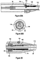
- the needle assembly 18 and the coring cannula are integrated into a single unit 18 , 20 (see Figure 2A ).
- the needle assembly 18 is inserted within the central passage 34 of the stylet housing 38 when the localization needle 54 is inserted into the breast ( Figure 2B ).
- a locking member actuation button 96 located on the top of the housing 14 is slid forward. The actuation button 96 is linked to the locking member 62 resulting in the locking member 62 being slid out of the localization needle 54 securing the target tissue.
- the localization needle 54 and locking member 82 are released from the housing 14 by actuation of one of the localization needle release button(s) 98 located thereon. This allows the device 10 to be slid up localization needle 54 (the stylet blades 32 separating the tissue allowing the stylet 28 and coring cannula 20 to pass. Once the coring cannula 20 is adjacent the target tissue, the process proceeds as above.
- the device 10 would be fed down the guide rod 104 and the process would proceed as above (see Figure 5A ).
- the central passage 34 is formed by the stylet tube 36 .
- the stylet tube 36 includes an opening 106 which allows the needle assembly 18 , 18B ' to pass into the central passage 34 .
- the stylet tube 36 also may include a guide portion 108 which extends past the opening 106 to assist in the placement of the guide rod into the central passage 34 .
- an independent needle assembly 18 ' may be provided (see Figures 3 , 4A , 4B , 5A, 5B ).
- the independent needle assembly 18 ' is separate from the coring cannula 20 .
- the independent needle assembly 18 ' includes a localization needle 54 ', an independent needle handle 100 , and a plunger 102 .
- the localization needle 54 ' is inserted into the breast tissue using the handle 100 . Once the target tissue is reached, the plunger 102 is pushed forward.
- the locking member 62 is pushed forward by the plunger 102 , pushing the wires 64 into the target tissue, thereby securing the target tissue.
- the localization needle 54 ' (and handle 100 ) may thereafter be removed, leaving the locking member 62 within the breast with a guide rod 104 extending out of the breast (see Figure 4B ).
- the localization needle 54 ' has a first end 54A ' and a second end 54 '.
- the localization needle includes an internal channel or bore 56 .
- the handle 100 has first and second ends 100A, 100B and an internal bore 268 .
- the first end 54A of the needle 54 ' is fixed to the second end of the handle 100B.
- the internal bore 56 of the needle 54 ' and the internal bore 268 of the handle 100 form an assembly bore 270 therethrough.
- the guide element 52 has a guide rod 104 and a locking member 62 .
- the guide element 104 has first and second ends 58 , 60 and is removably contained within the assembly bore 270 .
- the locking member 62 is fixed to the second end 60 of the guide rod 104 .
- the plunger 102 includes a pushrod 102B and an actuation element 102A coupled to the pushrod 102B.
- the plunger 102A is movable from a first state ( Figure 4A ) to a second state ( Figure 4B )
- One end of the pushrod 102B acts on the first end 58 of the guide rod 104 , forcing the locking member 62 out of the needle 18 ' as the pushrod 102 is moved from the first state to the second state.
- one of the wires 64 ' from the locking member 62 is detachable from the pushrod 70 . It should be noted that although Figures 19A-19D illustrated this feature with respect to the integrated needle assembly 18 , the detachable wire 64 ' concept may also be used with the independent needle assembly 18 '.
- the locking member 62 is contained within the localization needle 54 when the localization needle is initially inserted into the breast tissue.
- the locking member 62 is deployed as discussed above ( Figure 19B ) to secure the target tissue.
- the cannula 20 is advanced over the target tissue and severed using the severing mechanism 94 (see above).
- the localization needle 18 may be used to push the severed tissue from the cannula 20.
- the tissue anchors or wires 64 may then be retracted.
- the third hook 64 ' may either not be attached to the pushrod 70 or may be detachable therefore.
- the third hook or wire 64' remains attached or secured to the tissue to provide an orientation marker for the sample during pathology (see Figure 19D ).
- the guide rod 104 may include scale markings 110 to provide an indication to the user the depth of the anchor/guide element 52 within the breast, as shown in Figures 13A and 19B .
- the biopsy device 12 includes a flexible transection blade 112.
- the flexible transection blade 112 is a flat metal blade with one end sharpened is formatted to the required radius (see below).
- the blade thickness and material properties as such that the formed flexible transection blade 112 can be flattened out will "spring" back to its formed shape.
- the blade 112 will be held in a flat position along the side of the coring cannula.
- the coring cannula 20 will use an angled or non-continuous cutting ring (see below) at the completion of the coring process. As shown in Figures 20A and 20B , the coring cannula 20 is movable along the axis 24 from an initial cannula location 118 (shown in dotted lines) to a final cannula location 120 in response to rotation of the coring cannula 20 about the axis 24 in a first direction.
- the coring cannula 20 once the coring cannula 20 reaches the final cannula location 120, it will continue to rotate but will not advance axially forward.
- a mechanism 122 will be engaged to drive the flexible transection blade 112 forward.
- the flexible transection blade 112 exits the coring cannula 20 at a point slightly distal to the cutting edge of the coring cannula 20 (see Figures 21A and 21B ).
- the flexible blade 112 As the flexible blade 112 is driven out of the cannula 20, it will begin to return to its pre-formed curvature. Since this advancement is taking place while the coring cannula 20 is rotating, the result will be a curved, complete cut through the tissue.
- the path of the blade 112 is designed to intersect with the distal end of the cutting path from the coring cannula 20, resulting in complete transection and release of the tissue specimen.
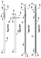
- the flexible transection blade 112 consists of a thin strip 124 of spring steel or nitinol.
- the flexible transection blade 112 has a first end 126 and a second or distal end 128.
- the flexible transection blade 112 is coupled to the coring cannula 20 at the first end 126 .
- the distal end 128 of the flexible transection blade 112 is cut to an optimized angle and sharpened to a cutting edge 114 (see Figure 23C ).
- a hole mount 130 may be provided for mounting the blade 112 to the drive assembly 40 .
- the flexible transection blade 112 is stored in a channel 116 built into the coring cannula 20 .
- the flexible transection blade 112 is held flat in this stored position.
- the coring cannula 20 will cease axial advancement, but will continue to rotate.
- the flexible blade 112 is driven forward, advancing past the coring cannula 20 .
- the flexible blade 112 advances, it will assume its pre-formed, curved position. Rotation causes the flexible blade 112 to create a semi-circular cut in the tissue.
- a complete cut results, releasing the tissue core.
- the curved blade 112 holds the tissue core inside the cannula 20 until removed from the breast.
- the flexible transection blade 112 has a first blade position and a second blade position.
- the flexible transection blade 112 is in the first blade position while the coring cannula 20 is between the initial and final cannula locations 118, 120.
- Figure 20A in one embodiment, when the flexible transection blade 112 is in the first blade position it is contained within the coring cannula 20, and thus, not visible.
- Rotation of the coring cannula 20 in the first direction while the coring cannula 20 is at the final cannula location 120 rotates the flexible transection blade 112 about the axis 24, moving the flexible transection blade 112 from the first blade position to the second blade position (shown in Figure 22B ).
- the most efficient cutting of tissue is accomplished by creating relative motion between cutting surface, i.e., the cutting edge 114, and tissue.
- the relationship between the cutting edge 114 and the rate of advancement of the length and angle of the cutting edge 114 must result in a cutting surface that is greater in length than the linear advancement per revolution. Further, the rate of advancement per revolution should be optimized to minimize cutting forces. This approach will ensure that a thin, flexible blade 112 will follow the desired cutting path.
- the mechanism 122 may include a friction wheel transmission 132 .
- the friction wheel transmission 132 includes friction wheel 134 which is force fit over the shaft 26 .
- the shaft 26 is directly coupled to the cannula 20 through a drive ring 20 which is fixed to the housing 14 .
- a drive screw 136 is fixed to the friction wheel 134 , which is coupled to the flexible transection blade 112 .
- the friction wheel 134 is force fit over the shaft 26 such that the transmission force may be controlled.
- the relationship between the friction wheel 134 and the drive ring 136 and/or the relationship between the friction wheel 134 and the shaft 26 can be adjusted so that if the force encountered by the flexible transection blade 112 increases to a certain point, the friction wheel 134 will slip on the shaft 26 preventing further advancement of the blade 112 . The blade 112 will continue to rotate until the sample tissue has been cut and the forces reduced. Blade advancement will then automatically resume.
- the mechanism 122 may include a gear drive transmission 140 .
- the gear drive transmission 140 provides continuous drive with maximum power transfer.
- the gears within the gear drive transmission 140 remain meshed but do not rotate during axial advancement of the coring cannula 20 .
- the gear drive transmission 140 automatically engages and begins to drive the flexible transection blade 112 .
- the gear drive transmission 140 may include a gear housing 146 , a ring gear 150 , and a drive gear 152 .
- a plunger 144 is slidably coupled to the gear housing 146 and is spring biased in an outward direction. While the coring cannula 20 is between the initial cannula location 118 and the final cannula location 120 , plunger 144 is pressed inwardly by the inner wall of the housing 20 such that one end is inserted a receiving slot 148 on the shaft 26 . Thus, the gear housing 146 is locked relative to the shaft 26 . The shaft gear housing 146 thereby rotates with the shaft 26 , and there is no relative motion between the gears 140, 152.
- a lead screw 156 is used to enable the shaft 26 to advance and rotate, stop advancing but continue rotating and then retract to its original position.
- the shaft 24 includes an opening 158 leading to a shaft threaded section 160 .
- the lead screw 156 is rotatably fixed to the housing 14 and includes a first end portion 162 , a second end portion 164 , and a lead screw threaded section 166 , which meshes with the shaft threaded section 160 .
- the shaft 26 is driven forward (to the right in Figure 29 ) until the back edge of shaft 174 reaches the front edge of lead screw threads 178 . At this position, the shaft 26 will continue to rotate but no longer advances.
- the shaft threaded portion 160 is supported by shoulder 180 .
- a first spring 168 makes contact with surface 172 exerting a slight backward force on the shaft 26 .
- This configuration may also be adopted to drive the flexible transection blade 112 .
- a drive screw 184 may be used to drive motion of the flexible transection blade 112 .
- a drive gear 182 is fixed to the drive screw 184 which is threadably coupled to the drive dog 186 .
- the drive dog 186 is allowed to slip relative to the drive screw 184 .
- the drive gear 182 and thus, the drive screw 184 rotate.
- the drive dog 186 has an internal threaded bore (not shown) which is mated with the drive screw 184.
- the drive dog 186 advances (or retracts) along the screw 184, thereby advancing the flexible transection blade 112.
- the drive dog 186' is fixed to an end of the drive screw 184'.
- the drive gear 182' has in internal threaded bore (not shown) which is mated with the drive screw 184'. As the drive gear 182' rotates, the drive screw 184' and the drive dog 186' advances or retracts.
- the cutting edge 114 of the cutting cannula 20 may be formed by a cannula insert 188 and may have different configurations.
- the cannula insert 188 forms a circular coring blade 190.
- the flexible transection blade 112 advances past the circular coring blade 190.
- the flexible blade 112 transects tissue distal to the front edge of cutting ring 190.
- the cannula insert 188 forms a partial cutting ring 192.
- the partial cutting ring 192 forms a partial cutting face 194 with an angled edge 196.
- the angled edge 196 cuts through the tissue.
- the flexible transection blade 112 does not extend past the furthermost edge of the partial cutting rung 192.
- the tissue sample is confined within the cutting ring 192.
- the cutting edge 114 of the flexible transection blade 112 is used to core the sample tissue ( Figure 34A ).
- the flexible transection blade 112 is then advanced to transect tissue ( Figure 34B ).
- a prior art cutting ring 200 is shown.
- the prior art cutting ring 200 is nestled within a bore 202 of the distal end of the cutting cannula 20.
- the coring cannula 20 has an inner diameter of d 1 and the cutting ring 200 has an inner diameter of d 2 .
- d 1 is substantially equally to d 2 .
- the outer surface of the coring cannula 205 has a ramping surface 206 from the outer dimension of the coring cannula 205 to the distal end of the coring cannula 205 .
- the outer diameter of the coring cannula d 4 is greater than the outer dimension, d 3 , of the prior art cutting ring 200 .
- the mechanism for transecting the tissue sample is a garrote wire 204 which transverses the outer wall of the coring cannula 20 .
- the garrote wire 204 forms a right angle and encircles the inner diameter of the coring cannula 20 . As shown, this occurs at a substantial distance, d 5 , from the distal end of the cutting ring 200 .
- This arrangement presents two problems. First, the 90 degree bend in the garrote wire 204 significantly increases the force required to pull the garrote wire and transect the tissue.
- the large distance, d 5 , between the garrote wire 204 and the cutting edge of the cutting ring 200 results in a core of tissue, or tissue plug, which is cored by the coring cannula 205 , but not transected by the garrote wire. This cored tissue thus remains in the breast.
- a partial cutting ring 208 may be provided.
- the illustrated partial cutting ring 208 may include a face cutting surface 208A , which has a cutting edge perpendicular to the axis 24 , and a side cutting surface 208B.
- the use of the side cutting surface 208B introduces side cutting. Side cutting is less likely to result in unwanted pushing or movement of tissue.
- the blade angle allows the garrote wire 210 to be installed outside of the coring blade and then clear of the cutting ring when retracting. This also limits the tissue plug problem identified above.
- the angle in the garrote wire 210 may be increased (as shown), reducing the required transection forces (see Figures 37A, 37B, 37C ).
- the coring cannula 20 may include an external cutting ring 198 .
- the external cutting ring 198 has an interior bore 212 within an interior diameter, d 2 .
- the coring cannula 20 has a reduced diameter portion 214 at its distal end.
- the external cutting ring 198 is fitted over the reduced diameter portion of the coring cannula 214.
- the outer diameter ( d 4 ) of the coring cannula 20 is substantially equal to the outer diameter of the external cutting ring, d 3 .
- the transecting mechanism 122 may include a garrote wire 210 .
- the garrote wire 210 is removably coupled to the coring cannula 20 by one or more bent tabs 216 formed integrally with the coring cannula 20 .
- the one or more bent tabs 216 may be integrally formed with the coring cannula 20 .
- the mechanism 122 is located at the distal end of the coring cannula 20 .
- the distal end of the coring cannula 20 is within a minimal distance of the distal end of the external cutting ring 198 . This minimizes the tissue plug problem discussed above.
- the minimal distance is ⁇ 0.64 cm ( ⁇ 0.25 inches).
- the distal end of the external cutting ring 198 is spaced from the distal end of the coring cannula 20 .
- the mechanism 122 is located at the distal end of the external cutting ring 198 .
- the mechanism 122 is within the minimal distance of the distal end of the external cutting ring 198 .
- the garrote wire may be removably held in place by one or more tabs 218 which may be formed integrally with the cutting ring 198 .
- the coring cannula 20 may be provided with a cutting ring in which the inner diameter of the coring cannula 20 has an inner diameter which is smaller than the inner diameter of the cutting ring.
- Tissue is flexible, malleable and compressible. With the inner diameter of the coring cannula 20 being smaller than the inner diameter of the cutting ring, the tissue sample is compressed as it enters the coring cannula 20 (behind the cutting ring). Compression of the tissue sample results in better retention of the tissue sample in the cannula 20 .
- the outer diameter of the cannula 20 may also be reduced, until it is the equal to or nearly equal to the outer diameter of the cutting ring. This results in (1) a smaller entry incision and (2) reduction of the required coring cutting force.
- a prior art cannula 222 is shown.
- the prior art cannula 222 has a cutting ring 224 .
- the prior art coring cannula 222 has an inner diameter ( d 1 ) which is equal to the inner diameter ( d 2 ) of the cutting ring 224 .
- the outer diameter ( d 4 ) of the prior art coring cannula 222 is greater than the outer diameter ( d 3 ) of the cutting ring 224 .
- a coring cannula 226 according to an arrangement is shown.
- the coring cannula 226 has a distal end 228 and is centered on the axis 24 and is coupled to the housing 14 .
- the coring cannula 226 having an inner surface 230 forming a cannula bore 232 .
- the cannula bore 232 has an inner diameter ( d 1 ) and is rotatable about the axis.
- a cutting ring 234 has an inner surface 236 which forms a cutting ring bore 238 and is located at the distal end of the coring cannula 226 .
- the cutting ring bore 238 has an interior diameter ( d 2 ).
- a tapered wall 240 is coupled between the coring cannula 226 and the cutting ring 234 .
- the tapered wall 240 provides a ramped surface between the inner surface 236 of the cutting ring 234 and the inner surface 236 of the coring cannula 226 .
- the inner diameter, d 1 , of the cannula bore 232 is less than the inner diameter, d 2 , of the cutting ring 234 .
- the outer diameter, d 4 , of the coring cannula 226 is equal to, or only slightly larger than, the outer diameter, d 3 , of the cutting ring 234 .
- the coring cannula 226 and the cutting ring 234 are unitarily formed. In another arrangement, the coring cannula 226 and the cutting ring 234 are formed separately. In one arrangement (as described above), the coring cannula 226 may have a reduced diameter portion formed at the distal end 228 .
- the cutting ring 234 is an external cutting ring which is fitted over the reduced diameter portion of the coring cannula. The distal end of the cutting ring 234 forms a coring cannula cutting edge 238 .
- a collapsible stylet may be provided (see below).
- a prior art stylet 242 is shown.
- the prior art stylet 242 is contained within the coring cannula 244 .
- the prior art stylet 242 has a slot 243 for the stylet blades 246 .
- the diameter, d 1 , of the prior art stylet 242 is fixed, and smaller than the diameter, d 2 , of the cutting edge 248 of the coring cannula 244 .
- the skin may need to be opened further to allow the coring cannula 244 to enter the tissue.
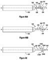
- a collapsible stylet 250 according to one arrangement is illustrated.
- the coring cannula 20 has a distal end 252 , a longitudinal axis 24 and is centered on the axis 24 (see above).
- the collapsible stylet 250 has a tip 254 , which contains at least one blade 256 , and a central passage 258 and is coupled to the coring cannula 20 .
- the tip 254 has a recess 260 located near a proximal end 262 thereof.
- the tip 254 is movable between an initial configuration (shown in Figures 43A and 43B ) and a contracted configuration (shown in Figures 43C and 43D ).
- the cutting edge 264 of the coring cannula 20 is within the recess 260 . This allows the coring cannula 20 to enter the incision with the stylet 250 , prior to the coring process, without the need to widen or open the incision any further.
- the tip 250 remains in the initial configuration as the coring cannula 20 is moved from the initial cannula location towards the final cannula location. Once the coring cannula 20 reaches the final cannula location, the tip may be moved into the contracted configuration ( Figure 43C ). In the contract configuration, the cutting edge 264 of the coring cannula 20 is exposed when the tip 254 is in the contracted configuration.
- the tip 254 has a first half portion 254A and a second half portion 254B.
- the first and second half portions 254A, 254B have a semi-circular cross-section (see Figures 43B and 43C ) and an inner surface 268A, 268B.
- the inner surface 266A of the first portion 254A faces the inner surface 266B of the second portion 254B .
- the first and second half portions 254A, 254B have a first part 268A, 268B and a second part 270A, 270B .
- the second parts 270A, 270B are sloped and curved forming an entry segment 272.
- the first and second parts 268A, 268B form a linear segment 274 .
- the linear segment 274 has an associated first diameter, ( d 1 ), when the tip is in the initial configuration ( Figure 43B ).
- the first diameter associated with the linear segment 274 is greater than or equal to a diameter associated with the cutting edge 248 of the coring cannula 20 .
- the cutting edge 248 can sit within the recess 260 prior to the coring process (see above).
- the linear segment 274 has a second diameter, ( d 2 ).
- the second diameter is less than diameter associated with the cutting edge 248 of the coring cannula 20 . This allows the coring cannula 20 to be rotated and moved forward (over the stylet) to perform the coring process.
- the first and second half portions 254A, 254B are biased towards the initial configuration.
- the collapsible stylet 250 includes a collet tube 251 and a collet closer 253.
- the tube 251 includes a ramping portion 251A and a distal end 251B .
- the distal end 251B is fitted between the first and second half portions 254A , 254B and bias the first and second half portions 254A , 254B into the initial configuration.
- a collet closer 253 is provided which is movable between a first position (shown in Figure 43A ) and a second position (shown in Figure 43C ).
- the collet closer 253 acts on the ramping portion 251A of the collet tube 251 to compress the distal end 251B. This allows the first and second half portions 254A, 254B of the collapsible stylet 250 to collapse to the contract position.
- the collet closer 253 may be movable from the first position to the second position by the user through actuation of a button provided on the housing 14 (not shown).
- an independent stylet mechanism 276 is provided.
- a prior art stylet 278 is shown.
- the prior art stylet 278 includes integral cutting blades 280. Since the integral cutting blades 280 are fixed relating to the stylet tip, the distance between the blades 280 and the stylet 278 is fixed at a minimal distance. This increases the chances of inadvertent movement or compression of the tissue, i.e., "snowplowing".
- the independent/retractable stylet mechanism 276 includes a tube 282 and at least one stylet blade 284 affixed to the tube 282 .
- a stylet 286 includes a stylet tip 288 with a central passage 290 .
- the tube 282 is slidably disposed within the central passage 290 of the stylet 286.
- the stylet mechanism 276 includes first and second blades 284A, 284B.
- the tube 282 may include an internal bore 292 for receiving the guide element 52 (see above).
- the independent/retractable stylet mechanism 276 is adjustable within/along the central passage 290 of the stylet 286 .
- the user can adjust the distance between the blades 284 and the stylet tip 288 to reduce the chance of snowplowing occurring.
- a localization needle with an integral locking member 294 is provided.
- the localization needle 294 includes a needle portion 296 and a locking member 304 .
- the needle portion 296 having a proximal end 298 , a distal end 300 and a channel 302 formed therein.
- the locking member 304 is formed integrally with the needle portion 296 . As shown, the locking member 304 may be formed at the distal end 300 of the needle portion 296 and has an unlocking configuration (shown in Figure 46A ) and a locking configuration (shown in Figure 46B ).
- the localization needle 294 in the unlocking configuration, is straight, i.e., without bends or kinks.
- bends, or barbs as shown in Figure 46B have been introduced into the localization needle 294 .
- bends, barbs are introduced into the localization needle 294 after the localization needle 294 has been inserted into the breast, thereby locking the localization needle 294 relative to the target tissue (see above).
- the localization needle 294 includes an actuation device 306 .
- the actuation device 306 is coupled to the distal end 300 and is used to apply a force thereto (see Figure 46B ). The force acts to bring the distal end 300 closer to the proximal end 298 .
- the localization needle 294 collapses at the locking member 304 creating the barbs, or extensions, as shown, thereby controllably moving the locking member from the unlocking configuration to the locking configuration.
- the actuation device 306 includes a member 308 coupled to an inner surface of the distal end 300 of the needle portion 296.
- the member 308 may include a wire 310 fixed to the inner diameter of the localization needle 294.
- the wire 310 may be attached to a lever (not shown) on the housing, or some other suitable mechanism, which pulls the wire 310 back toward the proximal end 298.
- the member 308 is a threaded rod 312 which is received by a threaded receiving member 314 which is coupled to the inner surface of the distal end 300 of the needle portion 296. This arrangement allows the localization needle 294 to be moved back into the unlocking configuration if the placement needs to be corrected.
- the locking member 304 is formed by at least one pair of opposed slots 316 within the needle portion 296.
- the slots 316 may be laser cut from the needle portion 296.
- the slots 316 may have a general rectangular shape with rounded ends.
- the slots 316 may include one or may directional cutouts 317 which assist in forming the extensions or barbs.
- the directional cutouts 317 may be triangular shaped.
- the slots 316 may have a general diamond shape, as shown in Figures 47A-47C .
- one or more rotating circular blades 318, 318A, 318B may be used.
- the use of the rotating circular blades 318, 318A, 318B improves the efficiency of the stylet and reduces the risk of compression and/or tearing of the tissue as the stylet in pushed into the breast.
- the rotating circular blade(s) 318, 318A, 318B may be powered (see below) or may rotating freely.
- the rotation of the blade (s) 318, 318A, 318B whether from an external source or as a result of friction between the blade 318, 318A, 318B and the tissue, creates relative motion therebetween.
- a stylet 320 is provided with a single rotating circular blade 318.
- the stylet 320 is coupled to a coring cannula 322.
- the coring cannula 322 has a longitudinal axis 324 and is centered on the axis 324.
- the stylet 320 is coupled to the coring cannula 322.
- the stylet 320 includes a stylet tube 326.
- the rotating circular blade 318 is rotatably coupled to a distal end 328 of the stylet tube 326.
- the rotating circular blade 318 is not mechanically driven, but is allowed to freely rotate. As the device 10 is advanced into the tissue, force exerted by the tissue will tend to rotate the circular blade 318, eliminating the tendency to push/tear tissue and improving cutting efficiency.
- the singular rotating circular blade 318 is mounted on its center point 334. As shown, the center point 334 is centered over the stylet tube 326.
- the rotating circular blade 318 defines a first plane which is parallel to the axis 324.
- the axis defines a second plane.
- the first and second planes intersect at a right angle.
- the center point 334 of the rotating circular blade 318 is located on both the first and second planes.
- a blade drive mechanism 330 is coupled to the rotating circular blade 318 for controllably rotating the circular blade 318.
- the blade drive mechanism 330 may include a motor (not shown) and drive cable 332.
- the blade drive mechanism 330 may include a rod and gearing system (not shown).
- the stylet 320 may include a pair of offset blades 318A, 318B.
- the second blade 318B defines a third plane which is parallel to the first plane.
- the center 334A, 334B of the blades 318A, 318B are offset a predetermined distance.
- the first and second blades 318A, 318B may be mechanically driven or may be allowed to rotate freely.
- the biopsy device 10 includes at least one retractable stylet blade 336.
- the at least one retractable stylet blade 336 is part of a stylet blade mechanism 338.
- the stylet blade mechanism 338 may include first and second retractable blades 336A, 336B, as shown.
- the stylet blade mechanism 338 is coupled to the coring cannula 20 via the stylet tip 30.
- the stylet blade mechanism 338 includes the stylet tube 36.
- the at least one retractable stylet blade 336 is fixed to the stylet tube 36.
- the stylet tube 36 is slidably disposed within the stylet housing 38.
- the central passage 34 is formed by the stylet tube 36.
- the stylet blade mechanism 338 is movable between a cutting position and a retracted position. In the cutting position, the at least one stylet blade is located a distance in front of the stylet tip 30 (as shown). In the retracted position, the at least one stylet blade 336 is located within the stylet tip 30.
- the stylet blade mechanism 338 may be manually moved from the retracted position to the cutting position. In one embodiment, the stylet blade mechanism 338 is spring biased towards the cutting position.
- the biopsy device 10 may further comprise a guide portion 108 formed at the end of the stylet tube 30.
- the guide portion 108 extends past an opening of the stylet tube 30.
- the guide portion 108 having an interior curved surface 340.
- the interior curved surface 340 assists in guiding the end of the guide element 52 into the central passageway 108.
- the stylet blade mechanism 338 and the retractable stylet blades 336 may be used with either integrated localization needle or the independent needle (see above).
- the stylet blade mechanism 338 is used with the independent needle handle assembly 18'. As discussed above, the independent needle handle assembly 18' is inserted into the breast, the guide element 52 is extended outside of the needle 54 and the locking member 62 is affixed to the target tissue. Once the locking member 62 is locked into the target tissue, the guide element 52 is removed from the needle 54. The guide element 52 is then inserted into central passageway 108.
- the biopsy device 10 With the guide element 52 within the central passageway 108 and the stylet blade mechanism 338 in the cutting position, the biopsy device 10 is slid up the guide element 52, the stylet blades 336 cutting the tissue and allowing the device 10 to reach the target tissue. Once the target tissue is reached, the stylet blade mechanism 338 can be retracted such that the blade(s) 336 are contained within the tip 30. The coring cannula 20 can then be advanced over the target tissue.
- a garrote wire 210 is used to transect the tissue sample.
- the prior art devices which employ a garrote wire, use a linear pull "trigger" system to activate the garrote wire.
- a limitation of the design is the travel required to fully pull the garrote wire. This limitation becomes an issue for larger cannula sizes. As the cannula diameter increases, the length of garrote wire required to transect tissue increases resulting in an increase in required travel. The travel length is limited by the overall length of the device. Continuing to increase the device length is not a viable option.
- the breast biopsy device 10 may include a trigger mechanism 342 which includes a trigger 344 (shown diagrammatically in Figures 50A-51B ).
- the trigger 344 is generally pulled backward to pull garrote wire 210 backward, thereby transecting the tissue sample within the coring cannula 20.
- the breast biopsy device 10 may include a pair of rotatable cleats 346 which are coupled to the housing 14 (through a trigger body 350 ) and are rotatable between a first cleat position (shown in Figure 50A ) and a second cleat position (shown in Figure 50B ).
- the rotatable cleats 346 include a plurality of teeth 348 which grip the garrote wire 210.
- the cleats 346 are coupled to the trigger mechanism 342 and when the trigger mechanism 342 is actuated, i.e., pulled backward relative to the housing 14. Friction causes the cleats 346 to rotate, thereby engaging the teeth 348 into the garrote wire 210. Then, as the trigger mechanism 342 is pulled backward, the cleats 346 move therewith, pulling the garrote wire 210 as well.
- the wire 210 when the garrote wire 210 is in a first position, the wire 210 forms a loop 352 which is external to the coring cannula 20. After the coring cannula 20 is extended and surrounds the sample tissue, the trigger mechanism 342 is used to complete separate the sample tissue from the breast.
- a single actuation of the trigger mechanism 342, e.g., a single pull of the trigger 342, moves the garrote wire 210 from the first wire position to a second wire position in which the garrote wire 210 is within the coring cannula 20 (and the sample completely separated from the breast).
- multiple actuations of the trigger mechanism 342, or multiple pulls of the trigger 344 are required.
- two pulls of the trigger 344 are required.
- Figure 50A shows the garrote wire 210 in an initial position with the loop 352 in its largest configuration.
- Figure 50B shows the garrote wire 210 in an intermediate location, after the first pull of the trigger 344 (the trigger 344 and trigger body 350 are shown at full travel).
- Figure 50C shows the garrote wire 210 at the intermediate location, with the trigger body 350 returned to the initial position.
- the trigger body 350 is spring biased back to the initial position.
- the trigger body 350 may be manually moved back to the initial position.
- Figure 50D shows the garrote wire 210 at the final location, fully actuated and within the coring cannula 20. At this point, the sample is completely severed from the breast.
- This improvement to the linear pull system will enable the use of larger cannula sizes to provide for multiple pulls of the trigger 344 on the garrote wire 210.
- Multiple pulls can be accomplished using the breakaway cleat system.
- the cleat system works as follows: When the trigger 348 is pulled, cleats 346 with separated edges or teeth 348 grip the garrote wire 210, allow the trigger 344 to pull the wire 219 the full length of travel. At the end of travel, the trigger 344 is pushed forward back to the start position. When the trigger 344 is moved in this direction, the cleat 346 (cam) disengages the wire so that the trigger 344 slides forward without affecting the wire 210. As the trigger 344 is pulled back, the cleats 346 re-engage the wire 210, pulling it to further transect tissue. This process is repeated until transection is completed.
- a second pair rotatable cleats 354 may be fixed directly to the device 10, e.g., directly to the housing 14.
- the second pair of rotatable cleats 354 are not fixed to the trigger body 350.
- the second pair of cleats 354 prevented undesirable forward motion of the garrote wire 210.
- the garrote wire 210 may have a number of beads 356 fixed thereto (crimped or welded thereon) to assist in grabbing of the wire by the cleats 346, 354.
- the prior art utilizes a linear pull trigger system, in which the trigger is pulled straight back to actuate the garrote wire.
- the trigger rides in a track and is supported by guide rods to maintain the desired linear pull.
- This support ring moves backward with the trigger, pulling the garrote wire across the cannula, transecting the core of tissue at the distal end.
- transection force increases significantly, at times resulting in incomplete transection. The user cannot provide enough input force to fully actuate the trigger system. Occurrences of this problem increases as cannula diameter increases.
- Phase 1 includes 0% to 70-95% constriction of the tissue by the garrote wire.
- the 70-95% range is dependent on cannula size and tissue density.
- the requirements of Phase 1 are long travel and low/medium input force.
- the current linear pull system works well during Phase 1.
- Phase 2 covers up to the final 30% of tissue constriction and eventual transection.
- the requirements of Phase 2 are limited travel with potentially high input forces required.
- the linear pull system does not always meet these requirements.
- the garrote wire 210 actuation by a trigger mechanism 358.
- the trigger mechanism 358 is coupled to the housing 14 and the garrote wire 210 (via support ring 370 ).
- the trigger mechanism 358 includes a trigger 360 slidably mounted in a trigger channel 362 in the housing 14.
- the trigger channel 362 is formed by a linear support track 368 within the housing 14.
- the trigger 360 is movable from a first trigger position (shown in Figure 52A and 52B ) to an intermediate trigger position (shown in Figure 52C ) within the trigger channel 362.
- the garrote wire 210 is coupled directly to the trigger 360.
- the garrote wire is moved from the first wire position to an intermediate wire position.
- the triggers 360 drops into a cam channel 366 once it reaches the intermediate trigger position.
- the trigger 360 is further rotatably movable about a trigger axis 364 from the intermediate trigger position to a second trigger position (shown dotted lines in Figures 52D ).
- the garrote wire 210 is moved from the intermediate wire position to the second wire position in response thereto.
- a rotational cam mechanism i.e., the rotatable trigger 360
- the rotational cam provides a mechanical advantage to the user allowing greater input force with limited travel.
- the concept described here is a "hybrid" system, using the linear pull system for the first 70-95% wire travel and then switching to the rotational cam system for the final phase of transection.
- the user will pull the trigger 360 along the linear track.
- the trigger 360 will reach the end of the trigger channel and engage the cam activation system. In this position the trigger will no longer translate, but will now rotate so that the input force is transferred through the cam to the support ring 370.
Description
- The present invention relates generally to surgical instruments, and more particularly, to a device for percutaneous excision of tissue, percutaneous excisional breast biopsy or percutaneous incisional breast biopsy.
- Generally, to date there have been two coring type, excisional breast biopsy devices developed and marketed. These devices are described in the following
US Patents: 5,111,828 ;5,197,484 ;5,353,804 ;6,080,113 ;6,267,732 ;6,383,145 ;6,551,253 ;5,782,775 ;5,817,034 ;5,857,982 ;6,036,657 ;6,077,231 ;6,165,137 ; and6,213,957 . - These devices were originally developed for use with stereotactic imaging equipment. Generally, these devices use the same basic technology. The device disclosed in the '253 patent is exemplary. The biopsy device includes a localization needle with a guide wire preloaded into the device. The localization needle and guide wire are used to locate and localize the target area. The methodology of their usage can be summarized as follows:
- 1. Localize the target area with needle/wire hook;
- 2. Translate device up to the target area using a bladed stylet;
- 3. Core out the target specimen using a bladed cannula; and
- 4. Transect the tissue using a garrote wire to release the specimen.
- The device can either by a handheld device or may be a fixed device. The below more detailed description of the method of using a prior art device is described with respect to a handheld device.
- First, a localization needle is placed at the center of the target tissue. A localization wire is used to fix the handheld device to the tissue. After the localization wire is deployed, a stylet is manually advanced to a point just proximal of the target.
- One problem associated with the current device is that the localization hook has very little holding power.
- Another issue related to the prior art devices is the potential of the stylet to push and/or compress, i.e., the tissue in front of the stylet, i.e., "snowplow'.
- After the stylet reaches the target tissue, the cannula is manually advanced over the target tissue. With the cannula advanced over the target tissue, a mechanism, such as a garrote wire is activated to sever the target tissue from the breast. With the target tissue severed from the breast, the device, along with the target tissue with the cannula, may be removed.
- Generally, these prior art devices are purely mechanical devices, i.e., in other words, the coring cannula is advanced by hand. The surgeon or user rotates a knob that activates a gear system to rotate and advances the coring cannula. This results in a relatively slow, intermittent advance of the cannula due to the start/stop motion of the surgeon. The start/stop motion can increase patient discomfort, as well as produce an undesirable irregular specimen shape.
- As discussed above, once the cannula has been advanced over the target tissue, a garrote wire may be used to cut the sample tissue (which is inside the cannula) from the breast so that it may be removed. The garrote wire has several limitations. Typically, the garrote wire traverse (at least partially) along the length of the device, then is bent at a 90 degree angle, after which it encircles an inner surface of the coring cannula. The right angle in the garrote wire results in requiring a large amount of force to pull on the garrote wire to transect the tissue sample. Additionally, the garrote wire is generally located a distance behind the cutting edge of the coring cannula. This results in a core of tissue which is cored by the coring cannula, which is not transected by the garrote wire, and thus remains in the breast. Furthermore, the garrote wire may tear the tissue rather than cutting the tissue. Additionally, dense tissue can be pushed aside rather than cut.
- Another issue related to prior art designs is the size of the cutting edge of the cannula with respect to the stylet. Prior to entry of the device into the breast, a skin incision is made using a scalpel. This incision is generally just slightly wider than the diameter of the cannula. Once the incision is made, the stylet is advanced in the breast, up to the point where the coring blade is ready to enter the incision. At this point, the surgeon will use nerve hooks to grab the skin and open the incision to allow the cutting edge of the cannula to enter the breast. However, the process of using the nerve hooks to grab the skin to make the incision wider can be cumbersome and inefficient and can cause patient discomfort.
- The current devices use a stylet with integral cutting blades. The flat stylet blades are fixed to the stylet which may result in several adverse conditions. First, the close proximity of the cutting edge of the stylet blades to the ramp or stylet tip results in the pushing or compression or other inadvertent movement of the tissue by the stylet. The prior designs also results in a fixed minimal proximal margin equal to the length of the stylet system.
- The present invention is aimed at one or more of the problems identified above. The invention is defined in
claim 1. Preferred embodiments are defined in dependent claims 2-12. A biopsy device according to the preamble ofclaim 1 is disclosed inUS-A-4 461 305 . - A biopsy device is provided. The device includes a housing, a coring cannula, and a flexible transection blade. The coring cannula has a longitudinal axis and is coupled to the housing. The coring cannula is rotatable about the axis. These flexible transection blade has a first end and a second end and is coupled to the coring cannula at the first end, the second end forming a cutting edge, the flexible transection blade having a first blade position and a second blade position, wherein rotation of the coring cannula in a first direction moves the flexible transection blade from the first blade position to the second blade position. In an aspect of the present invention the biopsy device includes a housing, a coring cannula, and a flexible transection blade. The coring cannula has a longitudinal axis and is centered on the axis and is coupled to the housing. The coring cannula is rotatable about the axis. The flexible transection blade has a first end and a second end and is coupled to the coring cannula, the second end forming a cutting edge, the flexible transection blade having a first blade position and a second blade position. In this aspect, the invention is characterized in that the coring cannula is movable along the axis from an initial cannula location towards a final cannula location in response to rotation of the coring cannula about the axis in a first direction, the flexible transection blade is in the first blade position while the coring cannula is between the initial and final cannula locations, wherein rotation of the coring cannula in the first direction while the coring cannula is at the final cannula location rotates the flexible transection blade about the axis, moving the flexible transection blade from the first blade position to the second blade position, where the flexible transection blade is at least partly contained within the coring cannula when the coring cannula is between the initial position and the final position, wherein motion of the flexible transection blade from the first blade position to the second blade position advances the transection blade past the coring cannula.
- Other advantages of the present invention will be readily appreciated as the same becomes better understood by reference to the following detailed description when considered in connection with the accompanying drawings wherein:
-
Figure 1 is a drawing of a biopsy device with an integrated needle, according to an embodiment of the present invention; -
Figure 2 includes a series of views of the biopsy device ofFigure 1 illustrating operation thereof; -
Figure 3 is an isometric drawing of a biopsy device with an independent needle assembly, according to an alternative embodiment of the present invention; -
Figure 4A is a drawing of the independent needle assembly ofFigure 3 ; -
Figure 4B is another drawing of the independent needle assembly ofFigure 3 ; -
Figure 5A is a drawing of a guide element of the independent needle assembly ofFigures 3 and4 ; -
Figure 5B is a larger view of a portion ofFigure 5A ; -
Figure 6 is an isometric illustration of a handheld breast biopsy device having a housing and a handle, according to an embodiment of the present invention; -
Figure 7 is a cut-away view of the handle of a breast biopsy device, according to an embodiment of the present invention; -
Figure 8 is a first cut-away view of a breast biopsy device illustrating the drivetrain components, according to an embodiment of the present invention; -
Figure 9 is a second cut-away view of the breast biopsy device ofFigure 8 ; -
Figure 10 is a drawing of the housing, according to an embodiment of the present invention; -
Figure 11 is a drawing of the stylet, according to an embodiment of the present invention; -
Figure 12 a drawing of the cannula, according to an embodiment of the present invention; -
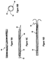
Figure 13A is an illustration of a guide element of an independent needle assembly, according to a first design; -
Figure 13B is an illustration of a partial view of the independent needle assembly ofFigure 13A , in the unlocking configuration; -
Figure 13C is an illustration of a partial view of the independent needle assembly ofFigure 13A , in the locking configuration; -
Figure 14 is an illustration of a guide element according to a second design, in the unlocking configuration; -
Figure 15 is an illustration of the guide element ofFigure 14A in the locking configuration; -
Figure 16A is an illustration of a guide element according to a fourth embodiment of the present invention; -
Figure 16B is a front view of the guide element ofFigure 16A in the unlocking configuration; -
Figure 16C is a side view of the guide element ofFigure 16A in the unlocking configuration; -
Figure 16D is a side view of the guide element ofFigure 16A in the locking configuration; -
Figure 17 is a side view of a guide element according to another design; -
Figure 18 is a side view of a guide element according to another design; -
Figure 19A is an illustration of a partial view of an integrated needle assembly with a guide element in the unlocking configuration; -
Figure 19B is an illustration of the integrated needle assembly ofFigure 19A with the guide element in the locking configuration; -
Figure 19C is an illustration of the integrated needle assembly ofFigure 19A with two three wires of the guide element retracted into the localization needle; -
Figure 19D is an illustration of a part of the guide element with a single wire which remains in the target tissue to provide orientation of the sample; -
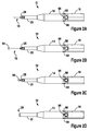
Figure 20A is a partial side view of a coring cannula in an initial position and a final position, according to an embodiment of the present invention; -
Figure 20B is a front view of the coring cannula ofFigure 20A ; -
Figure 21A is a partial side view of the coring cannula ofFigure 20B during initial advanced of a flexible transection blade; -
Figure 21B is a front view of the coring cannula and flexible transection blade ofFigure 21A ; -
Figure 22A is a partial side view of the coring cannula and flexible transection blade in a second blade position; -
Figure 22B is a front view of the coring cannula flexible transection blade in the second blade position; -
Figure 23A is a view of the flexible transection blade in an initial configuration, according to an embodiment of the present invention; -
Figure 23B is a top view of the flexible transection blade in a cutting configuration, according to an embodiment of the present invention; -
Figures 23C is a front view of the flexible transection blade in the cutting configuration showing a cutting edge, according to an embodiment of the present invention; -
Figure 24 is a graphical representation of the drivetrain of the device and the flexible transaction blade in the initial position, according to a first embodiment of the present invention; -
Figure 25A is a graphical representation of the drivetrain of the device and the flexible transaction blade, ofFigure 24 , in the final position; -
Figure 25B is a front view of the graphical representation of the drivetrain of the device and the flexible transaction blade, ofFigure 24 , in the final position; -
Figure 26 is a graphical representation of the drivetrain of the device and the flexible transaction blade in the initial position, according to a second embodiment of the present invention; -
Figure 27 is a graphical representation of the drivetrain of the device and the flexible transaction blade, ofFigure 24 , in the final position; -
Figure 28A is a first cut away view of the graphical representation of the drivetrain of the device and the flexible transaction blade, ofFigure 24 , in the final position; -
Figure 28B is a second cut away view of the graphical representation of the drivetrain of the device and the flexible transaction blade, ofFigure 24 , in the final position; -
Figure 29 is a graphical representation of an alternative drivetrain, according to an embodiment of the present invention; -
Figure 30 is a graphical representation of a second alternative drivetrain in an initial position, according to an embodiment of the present invention; -
Figure 31 is a graphical representation of the second alternative drivetrain in a final position; -
Figure 32A is a graphical representation of a flexible transection blade and a coring cannula with a circular cutting ring, according to an embodiment of the present invention; -
Figure 32B is a front view of the flexible transection blade and coring cannula ofFigure 32A ; -
Figure 33A is a graphical representation of a flexible transection blade and a coring cannula with a partial cutting ring, according to an embodiment of the present invention; -
Figure 33B is a front view of the flexible transection blade and coring cannula ofFigure 33A ; -
Figure 34A is a graphical representation of a flexible transection blade which forms the cutting edge of the coring cannula, according to an embodiment of the present invention; -
Figure 34B is a front view of the flexible transection blade and coring cannula ofFigure 34A ; -
Figure 35 is a graphical representation of a prior art coring cannula with an internal cutting ring; -
Figure 36A is a graphical representation of a coring cannula with an angled cutting ring, according to an embodiment of the present invention; -
Figure 36B is a front view of the coring cannula and cutting ring ofFigure 36A ; -
Figure 37A is a first view of a garrote wire for use with the cutting ring ofFigures 36A and 36B ; -
Figure 37B is a second view of a garrote wire for use with the cutting ring ofFigures 36A and 36B ; -
Figure 37C is a third view of a garrote wire for use with the cutting ring ofFigures 36A and 36B ; -
Figure 38A is a graphical representation of a coring cannula with an external cutting ring, according to an embodiment of the present invention; -
Figure 38B is a view of a portion of the coring cannula and external cutting ring ofFigure 38A ; -
Figure 39 is a graphical representation of a coring cannula with an external cutting ring, according to an other embodiment of the present invention; -
Figure 40 is a graphical representation of a prior art coring cannula with a cutting ring; -
Figure 41 is a graphical representation of a coring cannula with a cutting ring; -
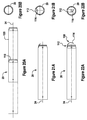
Figure 42A is a side view of a prior art coring cannula and stylet; -
Figure 42B is a front view of the prior art coring cannula and stylet ofFigure 42A ; -
Figure 43A is a side view of a coring cannula and a collapsible stylet in an initial configuration; -
Figure 43B is a first front view of the coring cannula and stylet ofFigure 43A ; -
Figure 43C is a side view of the coring cannula and stylet ofFigure 43A in a contracted configuration; -
Figure 43D is a second front view of the coring cannula and stylet ofFigure 43A with the stylet in the contracted configuration; -
Figure 44 is a view of a prior art stylet; -
Figure 45 is a view of a stylet including an independent stylet mechanism; -
Figure 46A is a first view of an expanding localization needle; -
Figure 46B is a second view of the expanding localization needle ofFigure 46A ; -
Figure 46C is a view of the expanding localization needle ofFigure 46A with an actuation mechanism; -
Figure 46D is a view of the expanding localization needle ofFigure 46A with an actuation mechanism; -
Figure 47A is a first view of an expanding localization needle; -
Figure 47B is a partial view of the expanding localization needle ofFigure 47A ; -
Figure 48A is a first view of a stylet with a rotating blade; -
Figure 48B is a second view of the stylet with the rotating blade ofFigure 48A ; -
Figure 49 is an illustration of a stylet with multiple rotating blades; -
Figure 50A is a graphical representation of a portion of a breast biopsy device with a garrote wire and a trigger mechanism including a pair of cleats; -
Figure 50B is a second graphical representation of the breast biopsy device ofFigure 50A ; -
Figure 50C is a third graphical representation of the breast biopsy device ofFigure 50A ; -
Figure 50D is a fourth graphical representation of the breast biopsy device ofFigure 50A ; -
Figure 51A is a graphical representation of another arrangement of the trigger mechanism ofFigure 50A ; -
Figure 51B is a graphical representation of a further arrangement of the trigger mechanism ofFigure 50A ; -
Figure 52A is a graphical representation of a top view of a breast biopsy device having a rotatable trigger; -
Figure 52B is a side view of the breast biopsy device ofFigure 52A ; -
Figure 52C is a second view of the breast biopsy device ofFigure 52A ; and -
Figure 52D is a third view of the breast biopsy device ofFigure 52A . - Referring to the Figures, wherein like numerals indicate like or corresponding parts throughout the several views, the present invention provides a
breast biopsy device 10 and a method of operating thebreast biopsy device 10. - With reference to
Figure 1 , in one aspect of the present invention, thebreast biopsy device 10 is embodied in ahandheld device 12. It should be noted that the present invention may be embodied in a fixed device (not shown). - The
handheld device 12 may include a housing 14 (seeFigure 10 ) and ahandle 16. In one embodiment, thehousing 14 is removable from thehandle 16. Thehandle 16 is reusable. The housing 14 (and all parts contained therein) are disposable and generally provided sterile. In one embodiment of the present invention, thedevice 10 may include an integrated needle assembly 18 (described below). In another embodiment of the present invention, thedevice 10 may include an independent needle assembly 18' (described below). - With particular reference to
Figures 10, 11 and 12 , thehousing 14 may include an inner passage 22 (seeFigure 10 ). Acoring cannula 20 is slidably mounted within theinner passage 22 of thehousing 14. Thecoring cannula 20 has alongitudinal axis 24 and may include ashaft 26 centered on theaxis 24. - In one embodiment, the
coring cannula 20 is coupled to the housing such that rotational movement of thecoring cannula 20 about theaxis 24 results in linear movement of thecoring cannula 20 along theaxis 24. As discussed more fully below, thecoring cannula 20 has a cutting edge allowing it to cut through tissue as it is rotated and advanced. - It should be noted that in other embodiments, the
coring cannula 20 may simply rotate within thehousing 14. Linear movement of the coring cannula 20 (to advance thedevice 10 and thecoring cannula 20 into the breast) may be provided by external mechanical means or by the user. - The
breast biopsy device 10 includes astylet 28, which includes astylet housing 38. With particular reference toFigure 11 , the stylet includes atip 30. Thetip 30 includes at least oneblade 32 and acentral passage 34. Thetip 30 may also include aslot 31 for the at least oneblade 32. - In one embodiment of the present invention, the
stylet 28 is mounted within thecoring cannula 20. Thestylet 28 includes first and second blades 32A, 32B integrated between twohalf portions stylet housing 38. Thestylet 28 transects, dilates, and separates tissue as thedevice 10 is inserted or advanced towards the biopsy site. - A
drive assembly 40 mounted within thehousing 14 and the handle 16 (seeFigures 7 and9 ) rotates thecannula 20 and controllably rotates thecannula 20. In one embodiment, thedrive assembly 40 also moves thecannula 20 in a direction parallel to (and along) theaxis 24. In one embodiment, thecoring cannula 20 has a predetermined linear advancement per revolution of thecoring cannula 20. In one embodiment, the predetermined linear advancement is 1.27 cm (0.50 inches) per revolution. In another embodiment, the predetermined linear advancement is 2.13 cm (0.84) inches per revolution. - The
drive assembly 40 may include a motor assembly comprised of a DC motor and step downtransmission 42 and adrivetrain 44. The DC motor and step downtransmission 42 is coupled to the drivetrain 44 (Figure 9 ). Thedrive assembly 40 and thedrivetrain 44 are explained more fully below. - In one embodiment of the present invention, the
drive assembly 40 rotates thecoring cannula 20 as a single speed, for example, at or around 80 revolutions per minute. Alternatively, thedrive assembly 40 rotates thecoring cannula 20 at a variable speed (see below). - The
needle assembly 18, 18' may include alocalization needle 54. Thelocalization needle 54 has aninner channel 56 and is slidably removable from the central passage of thestylet 28. Theneedle assembly 18, 18' further includes a guide element 52 (seeFigures 4 and5A ). Theguide element 52 is used to secure the tissue while thecoring cannula 20 is advanced. - In one embodiment of the present invention, the
guide element 52 has afirst end 58 and asecond end 60. Thefirst end 58 of theguide element 52 is slidably disposed within thechannel 56 of thelocalization needle 54. - In one embodiment, the
guide element 52 is composed, at least in part, of a metal alloy. In one embodiment, the metal alloy is composed of nickel and titanium. In one embodiment, the metal alloy is nitinol. - A locking
member 62 may be formed at thesecond end 60 of theguide element 52. The lockingmember 62 has an unlocking configuration and a locking configuration. The lockingmember 62 is in the unlocking configuration when theguide element 52 is in the first position, i.e., fully contained within the localization needle 54 (seeFigure 13B ). The lockingmember 62 is in the locking configuration when theguide element 52 is in the second position, i.e., then the lockingmember 62 is outside of the localization needle 54 (seeFigure 13C ). In the illustrated arrangement, thelocking wire 62 is formed ofmultiple wires 64, e.g., two, which are predisposed toward the locking configuration. When theguide element 52 is slid back into thelocalization needle 54, theinner channel 56 of thelocalization needle 54 constrains and confines thewires 64 in the unlocking configuration. Once theguide element 52 is slid towards and into the second position, thewires 64 are freed from the constraints on thelocalization needle 54 and allowed to move toward and into the locking configuration. - In one arrangement, the locking configuration is defined by a predefined shape of the
wires 64. In one arrangement, the predefined shape is a hook shape. - In one arrangement, wires (not shown) may be wrapped around the
wires 64 to provide rigidity to allow theguide element 52 to be moved within thelocalization needle 54. The number ofwires 64, as well as the diameter of the wires 64 (and wires used to provide rigidity) is optimized to provide maximize holding and as a function of the type of targeted tissue, e.g., hard or soft tissue. - With reference to
Figures 14 and 15 , in another arrangement, the lockingmember 62 may include a twisted pair ofwires 66. Theguide element 52 is shown in the first position inFigure 14 with the twisted pair ofwires 66 in the unlocking configuration. Theguide element 52 is shown in the second position inFigure 15 with the twisted pair ofwires 66 in the locking configuration. - With reference to
Figures 16A, 16B, 16C, and 16D , in another arrangement, the lockingmember 62 is formed from braided wire orcable 68. As shown, the distal ends of the cables may be straightened and then formed into a predetermined shape, such as a hook shape. The number of wires or cables may vary, e.g., the braided wire or cable may include 4, 7 or any number of individual wires or cables. Theguide element 52 is shown in the first position inFigure 16C with thebraided cable 68 in the unlocking configuration. Theguide element 52 is shown in the second position inFigure 16D with thebraided cable 68 in the locking configuration. - With reference to
Figures 17 and 18 , in another arrangement, theguide element 52 may include apushrod 70 and at least twoflexible fingers pushrod 70 andflexible fingers Figure 17 ). In another arrangement, theflexible fingers Figure 18 ). - In one arrangement, the
flexible fingers - Returning to
Figures 7 and9 , in one embodiment of the present invention, thedrive assembly 40 may include avariable speed circuit 74 electrically coupled to themotor assembly reverse switch 76 is electrically coupled to thevariable speed circuit 74. Aspeed control trigger 78 is electrically coupled to thevariable speed circuit 74. The forward/reverse switch 76 controls the direction of theDC motor 42, and thus, the direction of movement (forward/reverse) of thecannula 20 along theaxis 24. - The
variable speed circuit 74 controls the speed and rotation of thecannula 20 as a function of the forward/reverse switch 76 and actuation of thespeed control trigger 78. In one embodiment, thevariable speed circuit 74 has a predetermined speed range, for example 0-100 revolutions per minute. - The DC motor and
transmission 42 is powered by arechargeable battery 46, which may be charged via an external power source (not shown) through rechargingport 48. In one embodiment, therechargeable battery 46 is a lithium ion battery. - The DC motor and
transmission 42 is used to provide low speed and high torque to thedrivetrain 44. Adrive gear 50 is directly coupled between themotor 42 and thedrivetrain 44. - With specific reference to
Figures 7 ,8, and 9 , thedrivetrain 44 may include aspline gear 80, aspline gear support 82, alead screw 84, ashaft 86, and aring gear transmission 88. Thespline gear 80 is contained with thehousing 14 and is supported by thespline gear support 82. Thedrive gear 50 engages thespline gear 82 to transfer power to thedrivetrain 44, and thus, thecoring cannula 20. - The speed of the
DC motor 42 is controlled by user actuation of thespeed control trigger 78. Thevariable speed circuit 74 enables variable speed ramp up and slow down. In one embodiment, a speed range of approximately 0 -100 rpm at the cannula may be provided. - The
drivetrain 44 is contained within thehousing 14, which is removable coupled to thehandle 16. When thedevice 10 is assembled, thespline gear 80 engages thedrive gear 50 within thehandle 16. Power transferred through thedrive gear 50 causes rotation of thespline gear 80. Thespline gear 80 is attached to thespline gear support 82. Thespline gear support 82 is keyed to theshaft 86. The splinegear support key 82 provides rotation to theshaft 86 while allowing it to move axially (along axis 24). Thelead screw 84, which is fixed to thehousing 14, is engaged with threads at the proximal end of theshaft 86. Thecoring cannula 20 is attached to theshaft 86. As theshaft 86 is rotated, the threaded engagement with thelead screw 84 creates axial movement of thecoring cannula 20. - As the
cannula 20 rotates, it continues to move forward for a distance determined by the thread length on thelead screw 84. As theshaft 86 reaches the end of the threads, it will continue to rotate, but will no longer move forward. The timing is designed such that when theshaft 86 reaches the end of the threaded section of thelead screw 84, the transmission lockout (lock out button 90) engages. With the lock outbutton 90 engaged, thering gear assembly 88 is activated and begins to advance a drive dog 92 forward along thedrive screw 50. - The drive dog 92 is coupled to a severing mechanism 94 which is used to sever the tissue contained within the
coring cannula 20, which is described more fully below. - The general process of utilization of the device will now be described. First, the
localization needle 54 is advanced into the breast under ultrasound guidance. In one embodiment of the present invention, this is performed manually. For instance, with thehandheld device 10, the user manually inserts theneedle 54 by positioning and manually moving thedevice 10. When theneedle 54 reaches the target area, the tissue anchor or lockingmember 62 is advanced to secure the tissue prior to advancement of thedevice 10. Next, thelocalization needle 54 is released allowing thedevice 10 to move independently of theneedle 54. Thedevice 10 is now advanced into the breast, with thestylet blades 32 separating the tissue up to the target area. When thedevice 10 has reached the target area, thecoring cannula 20 is advanced. Thecannula 20 is advanced by depressing thespeed control trigger 78 on thehandle 16, with the forward/reverse switch 76 in a forward position. When thecannula 20 reaches its full core length, the severing mechanism 94 is actuated, separating the tissue core from surrounding tissue. In one embodiment, the severing mechanism 94 may include a flexible blade (see below) will automatically advance from the distal end of thecoring cannula 20. After the core of tissue has been cut free, thedevice 10 is removed from the breast. With the device out of the breast, the forward/reverse switch 76 is placed in a reverse position and the flexible blade is retracted using thespeed control trigger 78 allowing the tissue sample to be retrieved from the coring cannula. - As stated above, in one embodiment of the present invention, an
integrated needle assembly 18, as shown inFigure 1 and demonstrated inFigures 2A, 2B, 2C, and 2D , may be provided. With the integratedneedle assembly 18, theneedle assembly 18 and the coring cannula are integrated into asingle unit 18, 20 (seeFigure 2A ). With the integratedneedle assembly 18, theneedle assembly 18 is inserted within thecentral passage 34 of thestylet housing 38 when thelocalization needle 54 is inserted into the breast (Figure 2B ). Once thelocalization needle 54 reaches the target tissue, a lockingmember actuation button 96, located on the top of thehousing 14 is slid forward. Theactuation button 96 is linked to the lockingmember 62 resulting in the lockingmember 62 being slid out of thelocalization needle 54 securing the target tissue. - Once the target tissue is secured, the
localization needle 54 and lockingmember 82 are released from thehousing 14 by actuation of one of the localization needle release button(s) 98 located thereon. This allows thedevice 10 to be slid up localization needle 54 (thestylet blades 32 separating the tissue allowing thestylet 28 andcoring cannula 20 to pass. Once thecoring cannula 20 is adjacent the target tissue, the process proceeds as above. - Then, the
device 10 would be fed down theguide rod 104 and the process would proceed as above (seeFigure 5A ). - With respect to
Figure 5B , thecentral passage 34 is formed by thestylet tube 36. Thestylet tube 36 includes anopening 106 which allows theneedle assembly 18, 18B' to pass into thecentral passage 34. Thestylet tube 36 also may include aguide portion 108 which extends past theopening 106 to assist in the placement of the guide rod into thecentral passage 34. - In another embodiment of the present invention, an independent needle assembly 18' may be provided (see
Figures 3 ,4A ,4B ,5A, 5B ). The independent needle assembly 18' is separate from thecoring cannula 20. The independent needle assembly 18' includes a localization needle 54', anindependent needle handle 100, and aplunger 102. The localization needle 54' is inserted into the breast tissue using thehandle 100. Once the target tissue is reached, theplunger 102 is pushed forward. The lockingmember 62 is pushed forward by theplunger 102, pushing thewires 64 into the target tissue, thereby securing the target tissue. The localization needle 54' (and handle 100), may thereafter be removed, leaving the lockingmember 62 within the breast with aguide rod 104 extending out of the breast (seeFigure 4B ). - The localization needle 54' has a first end 54A' and a second end 54'. The localization needle includes an internal channel or bore 56. The
handle 100 has first and second ends 100A, 100B and an internal bore 268. The first end 54A of the needle 54' is fixed to the second end of the handle 100B. The internal bore 56 of the needle 54' and the internal bore 268 of thehandle 100 form an assembly bore 270 therethrough. In the illustrated embodiment, theguide element 52 has aguide rod 104 and a lockingmember 62. Theguide element 104 has first and second ends 58, 60 and is removably contained within the assembly bore 270. The lockingmember 62 is fixed to thesecond end 60 of theguide rod 104. Theplunger 102 includes apushrod 102B and anactuation element 102A coupled to thepushrod 102B. Theplunger 102A is movable from a first state (Figure 4A ) to a second state (Figure 4B ) One end of thepushrod 102B acts on thefirst end 58 of theguide rod 104, forcing the lockingmember 62 out of the needle 18' as thepushrod 102 is moved from the first state to the second state. - With reference to
Figures 19A-19D , in this arrangement one of the wires 64' from the lockingmember 62 is detachable from thepushrod 70. It should be noted that althoughFigures 19A-19D illustrated this feature with respect to theintegrated needle assembly 18, the detachable wire 64' concept may also be used with the independent needle assembly 18'. - As shown in
Figure 19A , the lockingmember 62 is contained within thelocalization needle 54 when the localization needle is initially inserted into the breast tissue. When thelocalization needle 54 reaches the target tissue, the lockingmember 62 is deployed as discussed above (Figure 19B ) to secure the target tissue. Then thecannula 20 is advanced over the target tissue and severed using the severing mechanism 94 (see above). Once thedevice 10 has been removed from the breast, thelocalization needle 18 may be used to push the severed tissue from thecannula 20. The tissue anchors orwires 64 may then be retracted. The third hook 64' may either not be attached to thepushrod 70 or may be detachable therefore. The third hook or wire 64' remains attached or secured to the tissue to provide an orientation marker for the sample during pathology (seeFigure 19D ). - In another arrangement, the
guide rod 104 may includescale markings 110 to provide an indication to the user the depth of the anchor/guide element 52 within the breast, as shown inFigures 13A and19B . - In another arrangement, the
biopsy device 12 includes aflexible transection blade 112. Theflexible transection blade 112 is a flat metal blade with one end sharpened is formatted to the required radius (see below). The blade thickness and material properties as such that the formedflexible transection blade 112 can be flattened out will "spring" back to its formed shape. Theblade 112 will be held in a flat position along the side of the coring cannula. - The
coring cannula 20 will use an angled or non-continuous cutting ring (see below) at the completion of the coring process. As shown inFigures 20A and 20B , thecoring cannula 20 is movable along theaxis 24 from an initial cannula location 118 (shown in dotted lines) to afinal cannula location 120 in response to rotation of thecoring cannula 20 about theaxis 24 in a first direction. - In one embodiment, once the coring
cannula 20 reaches thefinal cannula location 120, it will continue to rotate but will not advance axially forward. Amechanism 122 will be engaged to drive theflexible transection blade 112 forward. Theflexible transection blade 112 exits thecoring cannula 20 at a point slightly distal to the cutting edge of the coring cannula 20 (seeFigures 21A and 21B ). As theflexible blade 112 is driven out of thecannula 20, it will begin to return to its pre-formed curvature. Since this advancement is taking place while thecoring cannula 20 is rotating, the result will be a curved, complete cut through the tissue. The path of theblade 112 is designed to intersect with the distal end of the cutting path from thecoring cannula 20, resulting in complete transection and release of the tissue specimen. - With reference to
Figures 23A, 23B, and 23C , in one embodiment theflexible transection blade 112 consists of athin strip 124 of spring steel or nitinol. Theflexible transection blade 112 has afirst end 126 and a second ordistal end 128. Theflexible transection blade 112 is coupled to thecoring cannula 20 at thefirst end 126. Thedistal end 128 of theflexible transection blade 112 is cut to an optimized angle and sharpened to a cutting edge 114 (seeFigure 23C ). Ahole mount 130 may be provided for mounting theblade 112 to thedrive assembly 40. - In one embodiment as shown in
Figures 8 and 9 , theflexible transection blade 112 is stored in achannel 116 built into thecoring cannula 20. Theflexible transection blade 112 is held flat in this stored position. At the completion of the coring process, thecoring cannula 20 will cease axial advancement, but will continue to rotate. During this rotation theflexible blade 112 is driven forward, advancing past thecoring cannula 20. As theflexible blade 112 advances, it will assume its pre-formed, curved position. Rotation causes theflexible blade 112 to create a semi-circular cut in the tissue. When theflexible transection blade 112 advances past the center of rotation, a complete cut results, releasing the tissue core. Thecurved blade 112 holds the tissue core inside thecannula 20 until removed from the breast. - The
flexible transection blade 112 has a first blade position and a second blade position. Theflexible transection blade 112 is in the first blade position while thecoring cannula 20 is between the initial andfinal cannula locations Figure 20A , in one embodiment, when theflexible transection blade 112 is in the first blade position it is contained within thecoring cannula 20, and thus, not visible. Rotation of thecoring cannula 20 in the first direction while thecoring cannula 20 is at thefinal cannula location 120 rotates theflexible transection blade 112 about theaxis 24, moving theflexible transection blade 112 from the first blade position to the second blade position (shown inFigure 22B ). - Testing has revealed a few key elements of the invention. First, the most efficient cutting of tissue is accomplished by creating relative motion between cutting surface, i.e., the
cutting edge 114, and tissue. Second, the relationship between thecutting edge 114 and the rate of advancement of the length and angle of thecutting edge 114 must result in a cutting surface that is greater in length than the linear advancement per revolution. Further, the rate of advancement per revolution should be optimized to minimize cutting forces. This approach will ensure that a thin,flexible blade 112 will follow the desired cutting path. - With particular reference to
Figures 24 ,25A, and 25B , in one embodiment themechanism 122 may include a friction wheel transmission 132. The friction wheel transmission 132 includesfriction wheel 134 which is force fit over theshaft 26. Theshaft 26 is directly coupled to thecannula 20 through adrive ring 20 which is fixed to thehousing 14. Adrive screw 136 is fixed to thefriction wheel 134, which is coupled to theflexible transection blade 112. As theshaft 26 is advanced by thedrive assembly 40, thefriction wheel 134, and thus theflexible transection blade 116 is also advanced. Thefriction wheel 134 is force fit over theshaft 26 such that the transmission force may be controlled. The relationship between thefriction wheel 134 and thedrive ring 136 and/or the relationship between thefriction wheel 134 and theshaft 26 can be adjusted so that if the force encountered by theflexible transection blade 112 increases to a certain point, thefriction wheel 134 will slip on theshaft 26 preventing further advancement of theblade 112. Theblade 112 will continue to rotate until the sample tissue has been cut and the forces reduced. Blade advancement will then automatically resume. - With particular reference to
Figures 26 ,27, and 28 , in another embodiment themechanism 122 may include agear drive transmission 140. Thegear drive transmission 140 provides continuous drive with maximum power transfer. In one embodiment of the present invention, the gears within thegear drive transmission 140 remain meshed but do not rotate during axial advancement of thecoring cannula 20. When advancement of thecoring cannula 20 is complete, thegear drive transmission 140 automatically engages and begins to drive theflexible transection blade 112. - The
gear drive transmission 140 may include agear housing 146, aring gear 150, and adrive gear 152. Aplunger 144 is slidably coupled to thegear housing 146 and is spring biased in an outward direction. While thecoring cannula 20 is between theinitial cannula location 118 and thefinal cannula location 120,plunger 144 is pressed inwardly by the inner wall of thehousing 20 such that one end is inserted a receiving slot 148 on theshaft 26. Thus, thegear housing 146 is locked relative to theshaft 26. Theshaft gear housing 146 thereby rotates with theshaft 26, and there is no relative motion between thegears gear housing 146 reaches arelease slot 154 in thehousing 14, the springbiased plunger 144 slides into therelease slot 154, thereby releasing theshaft 26, thering gear 150 is fixed relative to thehousing 14 and thedrive gear 152 rotates with theshaft 26, thereby driving theflexible transection blade 112 forward. - With particular reference to
Figure 29 , in still another embodiment alead screw 156 is used to enable theshaft 26 to advance and rotate, stop advancing but continue rotating and then retract to its original position. Theshaft 24 includes anopening 158 leading to a shaft threadedsection 160. Thelead screw 156 is rotatably fixed to thehousing 14 and includes afirst end portion 162, asecond end portion 164, and a lead screw threadedsection 166, which meshes with the shaft threadedsection 160. - The
shaft 26 is driven forward (to the right inFigure 29 ) until the back edge ofshaft 174 reaches the front edge oflead screw threads 178. At this position, theshaft 26 will continue to rotate but no longer advances. The shaft threadedportion 160 is supported byshoulder 180. Afirst spring 168 makes contact withsurface 172 exerting a slight backward force on theshaft 26. - When the
drive assembly 40 is reversed, the force exerted onsurface 172 by thefirst spring 168 urges re-start of threads between theshaft 26 and thelead screw 156. Theshaft 26 will then move backward until thecontact surface 176 clears thesurface 172. Asecond spring 170 now provides force to urge restart in the forward direction. - This configuration may also be adopted to drive the
flexible transection blade 112. - With particular reference to
Figure 30 in still another embodiment, adrive screw 184 may be used to drive motion of theflexible transection blade 112. Adrive gear 182 is fixed to thedrive screw 184 which is threadably coupled to thedrive dog 186. During forward motion of thecoring cannula 20, thedrive dog 186 is allowed to slip relative to thedrive screw 184. During activation of theflexible transection blade 112, thedrive gear 182, and thus, thedrive screw 184 rotate. Thedrive dog 186 has an internal threaded bore (not shown) which is mated with thedrive screw 184. As thedrive screw 184 rotates, thedrive dog 186 advances (or retracts) along thescrew 184, thereby advancing theflexible transection blade 112. - With particular reference to
Figure 31 , in a further embodiment, a modification is shown. In the illustrated embodiment, the drive dog 186' is fixed to an end of the drive screw 184'. The drive gear 182' has in internal threaded bore (not shown) which is mated with the drive screw 184'. As the drive gear 182' rotates, the drive screw 184' and the drive dog 186' advances or retracts. - As discussed more fully below, the
cutting edge 114 of the cuttingcannula 20 may be formed by acannula insert 188 and may have different configurations. - With particular reference to
Figures 32A and 32B , thecannula insert 188 forms acircular coring blade 190. As shown theflexible transection blade 112 advances past thecircular coring blade 190. Theflexible blade 112 transects tissue distal to the front edge of cuttingring 190. - With particular reference to
Figures 33A and 33B , in another embodiment thecannula insert 188 forms apartial cutting ring 192. Thepartial cutting ring 192 forms apartial cutting face 194 with anangled edge 196. As thecoring cannula 20 rotates, theangled edge 196 cuts through the tissue. As shown, with thepartial cutting ring 192, theflexible transection blade 112 does not extend past the furthermost edge of thepartial cutting rung 192. Thus, the tissue sample is confined within the cuttingring 192. - With particular reference to
Figures 34A and 34B , in still another embodiment, thecutting edge 114 of theflexible transection blade 112 is used to core the sample tissue (Figure 34A ). Theflexible transection blade 112 is then advanced to transect tissue (Figure 34B ). - With particular reference to
Figure 35 , a priorart cutting ring 200 is shown. The priorart cutting ring 200 is nestled within abore 202 of the distal end of the cuttingcannula 20. As shown, thecoring cannula 20 has an inner diameter of d1 and thecutting ring 200 has an inner diameter of d2 . In the prior art device shown inFigure 35 , d1 is substantially equally to d2 . The outer surface of thecoring cannula 205 has a rampingsurface 206 from the outer dimension of thecoring cannula 205 to the distal end of thecoring cannula 205. As shown, the outer diameter of the coring cannula d4 is greater than the outer dimension, d3 , of the priorart cutting ring 200. - In the prior
art cutting ring 200 ofFigure 35 , the mechanism for transecting the tissue sample is agarrote wire 204 which transverses the outer wall of thecoring cannula 20. At a location near the distal end of thecoring cannula 205 thegarrote wire 204 forms a right angle and encircles the inner diameter of thecoring cannula 20. As shown, this occurs at a substantial distance, d5 , from the distal end of thecutting ring 200. This arrangement presents two problems. First, the 90 degree bend in thegarrote wire 204 significantly increases the force required to pull the garrote wire and transect the tissue. Second, the large distance, d5 , between thegarrote wire 204 and the cutting edge of thecutting ring 200, results in a core of tissue, or tissue plug, which is cored by thecoring cannula 205, but not transected by the garrote wire. This cored tissue thus remains in the breast. - With particular reference to
Figures 36A and 36B , in one embodiment apartial cutting ring 208 may be provided. The illustratedpartial cutting ring 208 may include aface cutting surface 208A, which has a cutting edge perpendicular to theaxis 24, and aside cutting surface 208B. The use of theside cutting surface 208B introduces side cutting. Side cutting is less likely to result in unwanted pushing or movement of tissue. Additionally, the blade angle allows thegarrote wire 210 to be installed outside of the coring blade and then clear of the cutting ring when retracting. This also limits the tissue plug problem identified above. Furthermore, the angle in thegarrote wire 210 may be increased (as shown), reducing the required transection forces (seeFigures 37A, 37B, 37C ). - With reference to
Figures 38A, 38B, and 39 in another aspect of the present invention, thecoring cannula 20 may include anexternal cutting ring 198. Theexternal cutting ring 198 has aninterior bore 212 within an interior diameter, d2 . Thecoring cannula 20 has a reduceddiameter portion 214 at its distal end. As shown, theexternal cutting ring 198 is fitted over the reduced diameter portion of thecoring cannula 214. As shown, the outer diameter (d4 ) of thecoring cannula 20 is substantially equal to the outer diameter of the external cutting ring, d3 . - As shown, the
transecting mechanism 122 may include agarrote wire 210. - With specific reference to
Figures 38A and 38B , in one embodiment thegarrote wire 210 is removably coupled to thecoring cannula 20 by one or morebent tabs 216 formed integrally with thecoring cannula 20. The one or morebent tabs 216 may be integrally formed with thecoring cannula 20. Themechanism 122 is located at the distal end of thecoring cannula 20. The distal end of thecoring cannula 20 is within a minimal distance of the distal end of theexternal cutting ring 198. This minimizes the tissue plug problem discussed above. In one embodiment, the minimal distance is ≤ 0.64 cm (≤ 0.25 inches). - With specific reference to
Figure 39 , the distal end of theexternal cutting ring 198 is spaced from the distal end of thecoring cannula 20. In the illustrated embodiment, themechanism 122 is located at the distal end of theexternal cutting ring 198. Themechanism 122 is within the minimal distance of the distal end of theexternal cutting ring 198. The garrote wire may be removably held in place by one ormore tabs 218 which may be formed integrally with the cuttingring 198. - With particular reference to
Figure 41 , in one arrangement, thecoring cannula 20 may be provided with a cutting ring in which the inner diameter of thecoring cannula 20 has an inner diameter which is smaller than the inner diameter of the cutting ring. Tissue is flexible, malleable and compressible. With the inner diameter of thecoring cannula 20 being smaller than the inner diameter of the cutting ring, the tissue sample is compressed as it enters the coring cannula 20 (behind the cutting ring). Compression of the tissue sample results in better retention of the tissue sample in thecannula 20. Additionally, with the reduced inner diameter of thecannula 20, the outer diameter of thecannula 20 may also be reduced, until it is the equal to or nearly equal to the outer diameter of the cutting ring. This results in (1) a smaller entry incision and (2) reduction of the required coring cutting force. - With particular reference to
Figure 40 , aprior art cannula 222 is shown. Theprior art cannula 222 has acutting ring 224. The priorart coring cannula 222 has an inner diameter (d1 ) which is equal to the inner diameter (d2 ) of thecutting ring 224. Additionally, the outer diameter (d4 ) of the priorart coring cannula 222 is greater than the outer diameter (d3 ) of thecutting ring 224. - With particular reference to
Figure 41 , acoring cannula 226 according to an arrangement is shown. Thecoring cannula 226 has adistal end 228 and is centered on theaxis 24 and is coupled to thehousing 14. Thecoring cannula 226 having aninner surface 230 forming acannula bore 232. The cannula bore 232 has an inner diameter (d1 ) and is rotatable about the axis. A cuttingring 234 has aninner surface 236 which forms a cutting ring bore 238 and is located at the distal end of thecoring cannula 226. The cutting ring bore 238 has an interior diameter (d2 ). Atapered wall 240 is coupled between thecoring cannula 226 and thecutting ring 234. Thetapered wall 240 provides a ramped surface between theinner surface 236 of thecutting ring 234 and theinner surface 236 of thecoring cannula 226. - As discussed, the inner diameter, d1 , of the cannula bore 232 is less than the inner diameter, d2 , of the
cutting ring 234. Furthermore, the outer diameter, d4 , of thecoring cannula 226 is equal to, or only slightly larger than, the outer diameter, d3 , of thecutting ring 234. - In one arrangement, the
coring cannula 226 and thecutting ring 234 are unitarily formed. In another arrangement, thecoring cannula 226 and thecutting ring 234 are formed separately. In one arrangement (as described above), thecoring cannula 226 may have a reduced diameter portion formed at thedistal end 228. The cuttingring 234 is an external cutting ring which is fitted over the reduced diameter portion of the coring cannula. The distal end of thecutting ring 234 forms a coringcannula cutting edge 238. - With reference to
Figures 42A, 42B, 43A, 43B ,43C , in another arrangement a collapsible stylet may be provided (see below). With particular reference toFigures 42A and 42B , aprior art stylet 242 is shown. Theprior art stylet 242 is contained within thecoring cannula 244. Theprior art stylet 242 has a slot 243 for thestylet blades 246. The diameter, d1 , of theprior art stylet 242 is fixed, and smaller than the diameter, d2 , of thecutting edge 248 of thecoring cannula 244. Thus, in use, after thestylet 242 has cut into the tissue, the skin may need to be opened further to allow thecoring cannula 244 to enter the tissue. - With particular reference to
Figures 43A, 43B , and43C , acollapsible stylet 250 according to one arrangement is illustrated. Thecoring cannula 20 has adistal end 252, alongitudinal axis 24 and is centered on the axis 24 (see above). Thecollapsible stylet 250 has a tip 254, which contains at least oneblade 256, and acentral passage 258 and is coupled to thecoring cannula 20. The tip 254 has arecess 260 located near aproximal end 262 thereof. The tip 254 is movable between an initial configuration (shown inFigures 43A and 43B ) and a contracted configuration (shown inFigures 43C and 43D ). When the tip 254 is in the initial configuration, thecutting edge 264 of thecoring cannula 20 is within therecess 260. This allows thecoring cannula 20 to enter the incision with thestylet 250, prior to the coring process, without the need to widen or open the incision any further. Thetip 250 remains in the initial configuration as thecoring cannula 20 is moved from the initial cannula location towards the final cannula location. Once thecoring cannula 20 reaches the final cannula location, the tip may be moved into the contracted configuration (Figure 43C ). In the contract configuration, thecutting edge 264 of thecoring cannula 20 is exposed when the tip 254 is in the contracted configuration. - In the illustrated arrangement, the tip 254 has a
first half portion 254A and asecond half portion 254B. As shown in the illustrated arrangement, the first andsecond half portions Figures 43B and43C ) and aninner surface inner surface 266A of thefirst portion 254A faces theinner surface 266B of thesecond portion 254B. The first andsecond half portions first part second part second parts entry segment 272. The first andsecond parts linear segment 274. Thelinear segment 274 has an associated first diameter, (d1 ), when the tip is in the initial configuration (Figure 43B ). The first diameter associated with thelinear segment 274 is greater than or equal to a diameter associated with thecutting edge 248 of thecoring cannula 20. Thus, thecutting edge 248 can sit within therecess 260 prior to the coring process (see above). - As shown in
Figure 43C , when the tip 254 is in the contracted configuration thelinear segment 274 has a second diameter, (d2 ). The second diameter is less than diameter associated with thecutting edge 248 of thecoring cannula 20. This allows thecoring cannula 20 to be rotated and moved forward (over the stylet) to perform the coring process. - In one arrangement, the first and
second half portions collapsible stylet 250 includes acollet tube 251 and acollet closer 253. As shown, thetube 251 includes a rampingportion 251A and adistal end 251B. Thedistal end 251B is fitted between the first andsecond half portions second half portions Figure 43A ) and a second position (shown inFigure 43C ). The collet closer 253 acts on the rampingportion 251A of thecollet tube 251 to compress thedistal end 251B. This allows the first andsecond half portions collapsible stylet 250 to collapse to the contract position. The collet closer 253 may be movable from the first position to the second position by the user through actuation of a button provided on the housing 14 (not shown). - With specific reference to
Figures 44 and 45 , in another arrangement, anindependent stylet mechanism 276 is provided. With particular reference toFigure 44 , aprior art stylet 278 is shown. Theprior art stylet 278 includesintegral cutting blades 280. Since theintegral cutting blades 280 are fixed relating to the stylet tip, the distance between theblades 280 and thestylet 278 is fixed at a minimal distance. This increases the chances of inadvertent movement or compression of the tissue, i.e., "snowplowing". - With specific reference to
Figure 45 , the independent/retractable stylet mechanism 276 includes atube 282 and at least onestylet blade 284 affixed to thetube 282. Astylet 286 includes astylet tip 288 with acentral passage 290. Thetube 282 is slidably disposed within thecentral passage 290 of thestylet 286. - In the illustrated arrangement, the
stylet mechanism 276 includes first andsecond blades - In one arrangement, the
tube 282 may include aninternal bore 292 for receiving the guide element 52 (see above). - The independent/
retractable stylet mechanism 276 is adjustable within/along thecentral passage 290 of thestylet 286. Thus, the user can adjust the distance between theblades 284 and thestylet tip 288 to reduce the chance of snowplowing occurring. - With reference to
Figures 46A-46D and47A-47C , in another arrangement, a localization needle with anintegral locking member 294 is provided. In one arrangement, thelocalization needle 294 includes aneedle portion 296 and a lockingmember 304. Theneedle portion 296 having aproximal end 298, adistal end 300 and achannel 302 formed therein. - The locking
member 304 is formed integrally with theneedle portion 296. As shown, the lockingmember 304 may be formed at thedistal end 300 of theneedle portion 296 and has an unlocking configuration (shown inFigure 46A ) and a locking configuration (shown inFigure 46B ). - In the illustrated arrangement, in the unlocking configuration, the
localization needle 294 is straight, i.e., without bends or kinks. In the locking configuration, bends, or barbs, as shown inFigure 46B have been introduced into thelocalization needle 294. These bends, barbs, are introduced into thelocalization needle 294 after thelocalization needle 294 has been inserted into the breast, thereby locking thelocalization needle 294 relative to the target tissue (see above). - In one arrangement, the
localization needle 294 includes anactuation device 306. Theactuation device 306 is coupled to thedistal end 300 and is used to apply a force thereto (seeFigure 46B ). The force acts to bring thedistal end 300 closer to theproximal end 298. With theproximal end 298 fixed to, for example, thehousing 14 of thebiopsy device 10, thelocalization needle 294 collapses at the lockingmember 304 creating the barbs, or extensions, as shown, thereby controllably moving the locking member from the unlocking configuration to the locking configuration. - In one arrangement, the
actuation device 306 includes amember 308 coupled to an inner surface of thedistal end 300 of theneedle portion 296. - With particular reference to
Figure 46C , in one arrangement themember 308 may include awire 310 fixed to the inner diameter of thelocalization needle 294. Thewire 310 may be attached to a lever (not shown) on the housing, or some other suitable mechanism, which pulls thewire 310 back toward theproximal end 298. - In another arrangement, the
member 308 is a threadedrod 312 which is received by a threaded receivingmember 314 which is coupled to the inner surface of thedistal end 300 of theneedle portion 296. This arrangement allows thelocalization needle 294 to be moved back into the unlocking configuration if the placement needs to be corrected. - In another arrangement, the locking
member 304 is formed by at least one pair ofopposed slots 316 within theneedle portion 296. In one arrangement, theslots 316 may be laser cut from theneedle portion 296. As shown inFigures 46A-46D , in one arrangement, theslots 316 may have a general rectangular shape with rounded ends. Theslots 316 may include one or may directional cutouts 317 which assist in forming the extensions or barbs. The directional cutouts 317 may be triangular shaped. - In another arrangement the
slots 316 may have a general diamond shape, as shown inFigures 47A-47C . - With particular reference to
Figures 48A, 48B, and 49 , in another arrangement, one or more rotatingcircular blades circular blades - The rotating circular blade(s) 318, 318A, 318B may be powered (see below) or may rotating freely. The rotation of the blade (s) 318, 318A, 318B whether from an external source or as a result of friction between the
blade - With particular reference to
Figure 48A , in one arrangement astylet 320 is provided with a single rotatingcircular blade 318. Thestylet 320 is coupled to acoring cannula 322. Thecoring cannula 322 has alongitudinal axis 324 and is centered on theaxis 324. Thestylet 320 is coupled to thecoring cannula 322. Thestylet 320 includes astylet tube 326. The rotatingcircular blade 318 is rotatably coupled to adistal end 328 of thestylet tube 326. - With particular reference to
Figure 48B , in another arrangement, the rotatingcircular blade 318 is not mechanically driven, but is allowed to freely rotate. As thedevice 10 is advanced into the tissue, force exerted by the tissue will tend to rotate thecircular blade 318, eliminating the tendency to push/tear tissue and improving cutting efficiency. - In both arrangements, the singular rotating
circular blade 318 is mounted on itscenter point 334. As shown, thecenter point 334 is centered over thestylet tube 326. - The rotating
circular blade 318 defines a first plane which is parallel to theaxis 324. The axis defines a second plane. The first and second planes intersect at a right angle. Thecenter point 334 of the rotatingcircular blade 318 is located on both the first and second planes. - A
blade drive mechanism 330 is coupled to the rotatingcircular blade 318 for controllably rotating thecircular blade 318. In one embodiment, theblade drive mechanism 330 may include a motor (not shown) and drivecable 332. Alternatively, theblade drive mechanism 330 may include a rod and gearing system (not shown). - With particular reference to
Figure 49 , thestylet 320 may include a pair of offsetblades second blade 318B defines a third plane which is parallel to the first plane. As shown inFigure 39 , thecenter blades second blades - Returning to
Figures, 2A-2D ,5A and 5B , in another embodiment of the present invention thebiopsy device 10 includes at least oneretractable stylet blade 336. The at least oneretractable stylet blade 336 is part of astylet blade mechanism 338. Thestylet blade mechanism 338 may include first and second retractable blades 336A, 336B, as shown. - The
stylet blade mechanism 338 is coupled to thecoring cannula 20 via thestylet tip 30. In one embodiment, thestylet blade mechanism 338 includes thestylet tube 36. The at least oneretractable stylet blade 336 is fixed to thestylet tube 36. Thestylet tube 36 is slidably disposed within thestylet housing 38. Thecentral passage 34 is formed by thestylet tube 36. - The
stylet blade mechanism 338 is movable between a cutting position and a retracted position. In the cutting position, the at least one stylet blade is located a distance in front of the stylet tip 30 (as shown). In the retracted position, the at least onestylet blade 336 is located within thestylet tip 30. - In one embodiment, the
stylet blade mechanism 338 may be manually moved from the retracted position to the cutting position. In one embodiment, thestylet blade mechanism 338 is spring biased towards the cutting position. - As discussed above, the
biopsy device 10 may further comprise aguide portion 108 formed at the end of thestylet tube 30. Theguide portion 108 extends past an opening of thestylet tube 30. Theguide portion 108 having an interiorcurved surface 340. The interiorcurved surface 340 assists in guiding the end of theguide element 52 into thecentral passageway 108. - It should be noted that the
stylet blade mechanism 338 and theretractable stylet blades 336 may be used with either integrated localization needle or the independent needle (see above). With respect toFigures 5A and 5B , thestylet blade mechanism 338 is used with the independent needle handle assembly 18'. As discussed above, the independent needle handle assembly 18' is inserted into the breast, theguide element 52 is extended outside of theneedle 54 and the lockingmember 62 is affixed to the target tissue. Once the lockingmember 62 is locked into the target tissue, theguide element 52 is removed from theneedle 54. Theguide element 52 is then inserted intocentral passageway 108. - With the
guide element 52 within thecentral passageway 108 and thestylet blade mechanism 338 in the cutting position, thebiopsy device 10 is slid up theguide element 52, thestylet blades 336 cutting the tissue and allowing thedevice 10 to reach the target tissue. Once the target tissue is reached, thestylet blade mechanism 338 can be retracted such that the blade(s) 336 are contained within thetip 30. Thecoring cannula 20 can then be advanced over the target tissue. - With reference to
Figures 50A, 50B ,50C, 50D ,51A and 51B , in still another arrangement, agarrote wire 210 is used to transect the tissue sample. - The prior art devices, which employ a garrote wire, use a linear pull "trigger" system to activate the garrote wire. A limitation of the design is the travel required to fully pull the garrote wire. This limitation becomes an issue for larger cannula sizes. As the cannula diameter increases, the length of garrote wire required to transect tissue increases resulting in an increase in required travel. The travel length is limited by the overall length of the device. Continuing to increase the device length is not a viable option.
- As discussed below, the
breast biopsy device 10 may include atrigger mechanism 342 which includes a trigger 344 (shown diagrammatically inFigures 50A-51B ). Thetrigger 344 is generally pulled backward to pullgarrote wire 210 backward, thereby transecting the tissue sample within thecoring cannula 20. - As shown in
Figure 50A , thebreast biopsy device 10 may include a pair ofrotatable cleats 346 which are coupled to the housing 14 (through a trigger body 350) and are rotatable between a first cleat position (shown inFigure 50A ) and a second cleat position (shown inFigure 50B ). As shown, in one arrangement, therotatable cleats 346 include a plurality ofteeth 348 which grip thegarrote wire 210. Thecleats 346 are coupled to thetrigger mechanism 342 and when thetrigger mechanism 342 is actuated, i.e., pulled backward relative to thehousing 14. Friction causes thecleats 346 to rotate, thereby engaging theteeth 348 into thegarrote wire 210. Then, as thetrigger mechanism 342 is pulled backward, thecleats 346 move therewith, pulling thegarrote wire 210 as well. - With specific reference to
Figure 50A , when thegarrote wire 210 is in a first position, thewire 210 forms aloop 352 which is external to thecoring cannula 20. After thecoring cannula 20 is extended and surrounds the sample tissue, thetrigger mechanism 342 is used to complete separate the sample tissue from the breast. - In one arrangement, a single actuation of the
trigger mechanism 342, e.g., a single pull of thetrigger 342, moves thegarrote wire 210 from the first wire position to a second wire position in which thegarrote wire 210 is within the coring cannula 20 (and the sample completely separated from the breast). - In another arrangement, multiple actuations of the
trigger mechanism 342, or multiple pulls of thetrigger 344, are required. In the illustrated embodiment, two pulls of thetrigger 344 are required. Each pull of thetrigger 344, moving the garrote wire a distance defined by the distance between X1 and X2 . -
Figure 50A shows thegarrote wire 210 in an initial position with theloop 352 in its largest configuration.Figure 50B shows thegarrote wire 210 in an intermediate location, after the first pull of the trigger 344 (thetrigger 344 and triggerbody 350 are shown at full travel). -
Figure 50C shows thegarrote wire 210 at the intermediate location, with thetrigger body 350 returned to the initial position. In one arrangement, thetrigger body 350 is spring biased back to the initial position. In another arrangement, thetrigger body 350 may be manually moved back to the initial position. -
Figure 50D shows thegarrote wire 210 at the final location, fully actuated and within thecoring cannula 20. At this point, the sample is completely severed from the breast. - This improvement to the linear pull system will enable the use of larger cannula sizes to provide for multiple pulls of the
trigger 344 on thegarrote wire 210. Multiple pulls can be accomplished using the breakaway cleat system. The cleat system works as follows: When thetrigger 348 is pulled,cleats 346 with separated edges orteeth 348 grip thegarrote wire 210, allow thetrigger 344 to pull the wire 219 the full length of travel. At the end of travel, thetrigger 344 is pushed forward back to the start position. When thetrigger 344 is moved in this direction, the cleat 346 (cam) disengages the wire so that thetrigger 344 slides forward without affecting thewire 210. As thetrigger 344 is pulled back, thecleats 346 re-engage thewire 210, pulling it to further transect tissue. This process is repeated until transection is completed. - With reference to
Figure 51A in a further arrangement, a second pairrotatable cleats 354 may be fixed directly to thedevice 10, e.g., directly to thehousing 14. The second pair ofrotatable cleats 354 are not fixed to thetrigger body 350. The second pair ofcleats 354 prevented undesirable forward motion of thegarrote wire 210. - With reference to
Figure 51B in another arrangement, thegarrote wire 210 may have a number ofbeads 356 fixed thereto (crimped or welded thereon) to assist in grabbing of the wire by thecleats - As discussed above, the prior art utilizes a linear pull trigger system, in which the trigger is pulled straight back to actuate the garrote wire. The trigger rides in a track and is supported by guide rods to maintain the desired linear pull. When the trigger is pulled back it engages a support ring attached to the garrote wire. This support ring moves backward with the trigger, pulling the garrote wire across the cannula, transecting the core of tissue at the distal end. However, there are a significant number of cases which encounter "tough" breast tissue. When tough tissue is encountered, transection force increases significantly, at times resulting in incomplete transection. The user cannot provide enough input force to fully actuate the trigger system. Occurrences of this problem increases as cannula diameter increases.
- Constriction and transection of breast tissue by the garrote wire can best be described by separating it into two phases.
Phase 1 includes 0% to 70-95% constriction of the tissue by the garrote wire. The 70-95% range is dependent on cannula size and tissue density. The requirements ofPhase 1 are long travel and low/medium input force. The current linear pull system works well duringPhase 1. Phase 2 covers up to the final 30% of tissue constriction and eventual transection. The requirements of Phase 2 are limited travel with potentially high input forces required. The linear pull system does not always meet these requirements. - With reference to
Figures 52A, 52B ,52C, and 52D , in another arrangement, thegarrote wire 210 actuation by atrigger mechanism 358. Thetrigger mechanism 358 is coupled to thehousing 14 and the garrote wire 210 (via support ring 370). In the illustrated embodiment, thetrigger mechanism 358 includes atrigger 360 slidably mounted in atrigger channel 362 in thehousing 14. In the illustrated arrangement thetrigger channel 362 is formed by alinear support track 368 within thehousing 14. Thetrigger 360 is movable from a first trigger position (shown inFigure 52A and 52B ) to an intermediate trigger position (shown inFigure 52C ) within thetrigger channel 362. - The
garrote wire 210 is coupled directly to thetrigger 360. In response to thetrigger 360 being moved from the first trigger position to the intermediate trigger position, the garrote wire is moved from the first wire position to an intermediate wire position. In the illustrated arrangement, thetriggers 360 drops into acam channel 366 once it reaches the intermediate trigger position. - Once the
trigger 360 reaches the intermediate trigger position it can move no further within thetrigger channel 362. Thetrigger 360 is further rotatably movable about a trigger axis 364 from the intermediate trigger position to a second trigger position (shown dotted lines inFigures 52D ). In response to movement of thetrigger 360 to the second trigger position, thegarrote wire 210 is moved from the intermediate wire position to the second wire position in response thereto. - The addition of a rotational cam mechanism, i.e., the
rotatable trigger 360, to thetrigger mechanism 358 will address Phase 2. The rotational cam provides a mechanical advantage to the user allowing greater input force with limited travel. The concept described here is a "hybrid" system, using the linear pull system for the first 70-95% wire travel and then switching to the rotational cam system for the final phase of transection. - In use, the user will pull the
trigger 360 along the linear track. At an optimized position, thetrigger 360 will reach the end of the trigger channel and engage the cam activation system. In this position the trigger will no longer translate, but will now rotate so that the input force is transferred through the cam to thesupport ring 370.
Claims (12)
- A biopsy device (10), comprising:a housing (14);a coring cannula (20) having a longitudinal axis (24) and being centered on the axis (24) and coupled to the housing (14), the coring cannula (20) rotatable about the axis (24); and,a flexible transection blade (112) having a first end (126) and a second end (128) and being coupled to the coring cannula (20), the second end (128) forming a cutting edge (114), the flexible transection blade (112) having a first blade position and a second blade position,characterized in that the coring cannula (20) being movable along the axis (24) from an initial cannula location (118) towards a final cannula location (120) in response to rotation of the coring cannula (20) about the axis (24) in a first direction, the flexible transection blade (112) being in the first blade position while the coring cannula (20) is between the initial and final cannula locations (118, 120), wherein rotation of the coring cannula (20) in the first direction while the coring cannula (20) is at the final cannula location (120) rotates the flexible transection blade (112) about the axis (24), moving the flexible transection blade (112) from the first blade position to the second blade position, where the flexible transection blade (112) being at least partly contained within the coring cannula (20) when the coring cannula (20) is between the initial position (118) and the final position (120), wherein motion of the flexible transection blade (112) from the first blade position to the second blade position advances the transection blade (112) past the coring cannula (20).
- A biopsy device (10), as set forth in claim 1, further comprising:a stylet (28) having a tip (30) containing at least one blade (32) and a central passage (34);a motor assembly coupled to the coring cannula (20) for controllably rotating the cannula (20);a circuit (74) electrically coupled to the motor assembly; and,a control trigger (78) electrically coupled to the circuit (74), the circuit (74) for responsively controlling rotation of the cannula (20) as a function of actuation of the control trigger (78).
- A biopsy device (10), as set forth in claim 2, wherein the circuit (74) is a variable speed circuit (74) which controls rotational speed of the cannula (20) as a function of a level of actuation of the speed control trigger (78).
- A biopsy device (10), as set forth in claim 2, further comprising a localization needle (54) having a channel (56) and being slidably disposed within the central passage (34) of the stylet (28).
- A biopsy device (10) as set forth in Claim 1, the flexible transection blade (112) having an initial configuration and a cutting configuration and being predisposed towards the cutting configuration, the flexible transection blade (112) being in the initial configuration at the first blade position and the cutting configuration at the second blade position.
- A biopsy device (10) as set forth in Claim 1, further comprising:a stylet (28) having a tip (30) containing at least one blade (32) and a central passage (34);a localization needle (54) having a channel (56) and being slidably disposed within the central passage (34);a motor assembly coupled to the coring cannula (20) for controllably rotating;a variable speed circuit (74) electrically coupled to the motor assembly;a forward/reverse switch (76) electrically coupled to the variable speed circuit (74) for controlling the direction of movement of the cannula (20);a speed control trigger (78) electrically coupled to the variable speed circuit (74), the variable speed circuit (74) for responsively controlling rotational speed of the cannula (20) as a function of the forward/reverse switch (76) and actuation of the speed control trigger (78); anda guide element (52) having a first end (58) and a second end (60) and being slidably disposed within the channel (56) of the localization needle (54), the guide element (52) being movable from a first position to a second position within the localization needle (54).
- A biopsy device (10) as set forth in claim 1, further comprising:a stylet (28) having a tip (30) containing at least one blade (32) and a central passage (34);a motor assembly coupled to the coring cannula (20) for controllably rotating the cannula (20);a variable speed circuit (74) electrically coupled to the motor assembly;a forward/reverse switch (76) electrically coupled to the variable speed circuit (74) for controlling the direction of movement of the cannula (20); anda speed control trigger (78) electrically coupled to the variable speed circuit (74), the variable speed circuit (74) for responsively controlling rotational speed of the cannula (20) as a function of the forward/reverse switch (76) and actuation of the speed control trigger (78); further comprising a needle assembly (18) comprising:a localization needle (54) having a channel (56) and being slidably disposed within the central passage (34); anda guide element (52) having a first end (58) and a second end (60) and being slidably disposed within the channel (56) of the localization needle (54) and removable therefrom; wherein, in use, the stylet (28) is adapted to receive the guide element (52) within the central passage (34) when removed from the localization needle (54), and the biopsy device (10) being advanced relative to the guide element (52) such that the guide element (52) moves from a first position to a second position within the central passage (34).
- A biopsy device (10), as set forth in any of claims 1, 5 or 6, wherein the flexible transection blade (112) has an initial configuration and a cutting configuration, wherein the flexible transection blade (112) is predisposed towards the cutting configuration; and preferably wherein the initial configuration is generally flat and the cutting configuration is generally curved.
- A biopsy device (10), as set forth in claim 8, wherein the flexible transection blade (112) is in the initial configuration at the first blade position and in the cutting configuration at the second blade position.
- A biopsy device (10), as set forth in any of claims 1, 5 or 6, wherein the flexible blade element is composed of a metal alloy of nickel and titanium.
- A biopsy device (10), as set forth in claim 10, wherein the metal alloy is nitinol.
- A biopsy device (10), as set forth in any of claims 1, 5 or 6, wherein the flexible blade element is predisposed to the second position through a heat treat process.
Applications Claiming Priority (14)
| Application Number | Priority Date | Filing Date | Title |
|---|---|---|---|
| US31914810P | 2010-03-30 | 2010-03-30 | |
| US31915510P | 2010-03-30 | 2010-03-30 | |
| US31920910P | 2010-03-30 | 2010-03-30 | |
| US31921010P | 2010-03-30 | 2010-03-30 | |
| US31915910P | 2010-03-30 | 2010-03-30 | |
| US31916210P | 2010-03-30 | 2010-03-30 | |
| US31921710P | 2010-03-30 | 2010-03-30 | |
| US31921810P | 2010-03-30 | 2010-03-30 | |
| US31922310P | 2010-03-30 | 2010-03-30 | |
| US31915710P | 2010-03-30 | 2010-03-30 | |
| US31916010P | 2010-03-30 | 2010-03-30 | |
| US31952810P | 2010-03-31 | 2010-03-31 | |
| US32417210P | 2010-04-14 | 2010-04-14 | |
| PCT/US2011/030334 WO2011123446A1 (en) | 2010-03-30 | 2011-03-29 | Tissue excision device |
Publications (2)
| Publication Number | Publication Date |
|---|---|
| EP2552322A1 EP2552322A1 (en) | 2013-02-06 |
| EP2552322B1 true EP2552322B1 (en) | 2016-11-16 |
Family
ID=44710484
Family Applications (1)
| Application Number | Title | Priority Date | Filing Date |
|---|---|---|---|
| EP11713575.6A Not-in-force EP2552322B1 (en) | 2010-03-30 | 2011-03-29 | Tissue excision device |
Country Status (3)
| Country | Link |
|---|---|
| US (13) | US8597201B2 (en) |
| EP (1) | EP2552322B1 (en) |
| WO (1) | WO2011123446A1 (en) |
Families Citing this family (41)
| Publication number | Priority date | Publication date | Assignee | Title |
|---|---|---|---|---|
| WO2011123446A1 (en) * | 2010-03-30 | 2011-10-06 | Flatland Martin L | Tissue excision device |
| WO2012068315A1 (en) | 2010-11-21 | 2012-05-24 | Robert Peliks | Tissue removal device and method of use |
| US8801742B2 (en) | 2011-06-01 | 2014-08-12 | Devicor Medical Products, Inc. | Needle assembly and blade assembly for biopsy device |
| US9161759B2 (en) * | 2011-06-24 | 2015-10-20 | Covidien Lp | Method and apparatus for storage and/or introduction of anatomical implant |
| US8850130B1 (en) | 2011-08-10 | 2014-09-30 | Nutanix, Inc. | Metadata for managing I/O and storage for a virtualization |
| US8549518B1 (en) | 2011-08-10 | 2013-10-01 | Nutanix, Inc. | Method and system for implementing a maintenanece service for managing I/O and storage for virtualization environment |
| US9009106B1 (en) | 2011-08-10 | 2015-04-14 | Nutanix, Inc. | Method and system for implementing writable snapshots in a virtualized storage environment |
| US8863124B1 (en) | 2011-08-10 | 2014-10-14 | Nutanix, Inc. | Architecture for managing I/O and storage for a virtualization environment |
| US8601473B1 (en) | 2011-08-10 | 2013-12-03 | Nutanix, Inc. | Architecture for managing I/O and storage for a virtualization environment |
| US9652265B1 (en) | 2011-08-10 | 2017-05-16 | Nutanix, Inc. | Architecture for managing I/O and storage for a virtualization environment with multiple hypervisor types |
| US9747287B1 (en) * | 2011-08-10 | 2017-08-29 | Nutanix, Inc. | Method and system for managing metadata for a virtualization environment |
| BR112014008970A2 (en) | 2011-10-15 | 2017-05-02 | Transmed7 Llc | methods and devices for soft tissue control biopsy |
| US9772866B1 (en) | 2012-07-17 | 2017-09-26 | Nutanix, Inc. | Architecture for implementing a virtualization environment and appliance |
| WO2014031995A2 (en) | 2012-08-23 | 2014-02-27 | Heartware, Inc. | Coring tool |
| EP2922478B1 (en) | 2012-11-21 | 2020-03-11 | C.R. Bard, Inc. | Core needle biopsy device |
| US9039633B2 (en) | 2012-12-24 | 2015-05-26 | Transmed7, Llc | Automated, selectable, soft tissue excision biopsy devices and methods |
| BR112015019440A8 (en) * | 2013-02-20 | 2019-11-12 | Cytrellis Biosystems Inc | adjustable dressing, kit, use and method for skin strengthening |
| US9463001B2 (en) | 2013-05-28 | 2016-10-11 | Transmed7, Llc | Soft tissue coring biopsy devices and methods |
| US9155527B2 (en) | 2013-08-22 | 2015-10-13 | Transmed7, Llc | Soft tissue coring biopsy devices and methods |
| US9204867B2 (en) | 2013-08-31 | 2015-12-08 | Robert Bilgor Peliks | Tissue removal device and method of use |
| US10555751B2 (en) | 2013-09-12 | 2020-02-11 | Transmed7, Llc | Soft tissue coring biopsy devices and methods |
| EP3038549B1 (en) | 2013-09-27 | 2019-08-07 | Release Medical, Inc. | Tissue incision device |
| US10028762B1 (en) | 2013-10-14 | 2018-07-24 | Percutaneous Cosmetic Devices LLC | Method of cutting soft tissue under facial skin |
| US10076315B2 (en) * | 2014-09-18 | 2018-09-18 | Transmed7, Llc | Soft tissue biopsy or excisional devices and methods |
| US9999758B2 (en) | 2014-09-19 | 2018-06-19 | Transmed7, Llc | In-situ material delivery devices and methods |
| US10231750B2 (en) | 2014-09-29 | 2019-03-19 | Transmed7, Llc | Excisional device distal working end actuation mechanism and method |
| WO2016077759A1 (en) | 2014-11-14 | 2016-05-19 | Cytrellis Biosystems, Inc. | Devices and methods for ablation of the skin |
| US20160151054A1 (en) | 2014-12-02 | 2016-06-02 | Byungesol An | Disposable biopsy devices and methods of obtaining tissue biopsy samples using same |
| US11213308B2 (en) | 2015-01-08 | 2022-01-04 | Sinusafe Medical Ltd | Paranasal sinus medical device and uses thereof |
| US10251630B2 (en) | 2015-08-28 | 2019-04-09 | SiteSelect Inc. | Tissue excision device with anchor stability rod and anchor stability rod |
| US20170055963A1 (en) * | 2015-08-28 | 2017-03-02 | SiteSelect Inc. | Tissue excision device with expanding cannula and expanding cannula |
| EP3340889A4 (en) * | 2015-08-28 | 2019-05-08 | Siteselect Inc. | Tissue excision device with anchor stability rod and anchor stability rod |
| US10467103B1 (en) | 2016-03-25 | 2019-11-05 | Nutanix, Inc. | Efficient change block training |
| WO2017180761A1 (en) * | 2016-04-12 | 2017-10-19 | The Administrators Of The Tulane Educational Fund | Biopsy cutter and methods of use therefor |
| WO2018008020A1 (en) | 2016-07-03 | 2018-01-11 | Sinusafe Medical Ltd. | Medical device for treatment of a sinus and/or an ear and methods of use thereof |
| US10285723B2 (en) * | 2016-08-09 | 2019-05-14 | Ethicon Llc | Ultrasonic surgical blade with improved heel portion |
| BR112019005312A2 (en) | 2016-09-21 | 2019-07-16 | Cytrellis Biosystems Inc | devices and methods for skin cosmetic restoration |
| KR102056153B1 (en) * | 2017-11-14 | 2019-12-16 | 주식회사 엔도비전 | Bidirectional vertebral endoscopic device for surgery |
| FR3073729A1 (en) * | 2017-11-22 | 2019-05-24 | Laurent Fumex | DEVICE FOR ANCHORING AND IDENTIFYING SUSPECTED LESIONS WITH MULTIPLE ANCHORING DEVICES |
| WO2019155472A1 (en) | 2018-02-08 | 2019-08-15 | Limaca Medical Ltd. | Biopsy device |
| WO2020206413A1 (en) | 2019-04-04 | 2020-10-08 | Transmed7, Llc | Excisional devices and methods |
Family Cites Families (149)
| Publication number | Priority date | Publication date | Assignee | Title |
|---|---|---|---|---|
| US4461305A (en) * | 1981-09-04 | 1984-07-24 | Cibley Leonard J | Automated biopsy device |
| US4616656A (en) | 1985-03-19 | 1986-10-14 | Nicholson James E | Self-actuating breast lesion probe and method of using |
| US4790329A (en) | 1987-06-12 | 1988-12-13 | Trustees Of Beth Israel Hospital | Adjustable biopsy localization device |
| US5115175A (en) * | 1988-02-03 | 1992-05-19 | Hall Surgical | Drill having alternate mode control |
| US5060658A (en) | 1988-02-23 | 1991-10-29 | Vance Products Incorporated | Fine-needle aspiration cell sampling apparatus |
| US5069679A (en) | 1989-02-16 | 1991-12-03 | Taheri Syde A | Method and apparatus for removing venous valves |
| US4986279A (en) | 1989-03-01 | 1991-01-22 | National-Standard Company | Localization needle assembly with reinforced needle assembly |
| US5197482A (en) | 1989-06-15 | 1993-03-30 | Research Corporation Technologies, Inc. | Helical-tipped lesion localization needle device and method of using the same |
| US5415169A (en) | 1989-11-21 | 1995-05-16 | Fischer Imaging Corporation | Motorized mammographic biopsy apparatus |
| US5030201A (en) | 1989-11-24 | 1991-07-09 | Aubrey Palestrant | Expandable atherectomy catheter device |
| US5114401A (en) * | 1990-02-23 | 1992-05-19 | New England Deaconess Hospital Corporation | Method for central venous catheterization |
| US5454365A (en) | 1990-11-05 | 1995-10-03 | Bonutti; Peter M. | Mechanically expandable arthroscopic retractors |
| US5111828A (en) | 1990-09-18 | 1992-05-12 | Peb Biopsy Corporation | Device for percutaneous excisional breast biopsy |
| US5353804A (en) | 1990-09-18 | 1994-10-11 | Peb Biopsy Corporation | Method and device for percutaneous exisional breast biopsy |
| CA2093821A1 (en) | 1990-10-09 | 1992-04-10 | Walter R. Pyka | Device or apparatus for manipulating matter |
| DE9016810U1 (en) | 1990-12-12 | 1991-02-28 | Siemens Ag, 8000 Muenchen, De | |
| US5591186A (en) * | 1991-05-22 | 1997-01-07 | Wurster; Helmut | Self-cutting trocar |
| US5199441A (en) | 1991-08-20 | 1993-04-06 | Hogle Hugh H | Fine needle aspiration biopsy apparatus and method |
| US7549424B2 (en) | 1991-10-18 | 2009-06-23 | Pro Surg, Inc. | Method and apparatus for tissue treatment with laser and electromagnetic radiation |
| US5289520A (en) | 1991-11-27 | 1994-02-22 | Lorad Corporation | Stereotactic mammography imaging system with prone position examination table and CCD camera |
| AU3475493A (en) | 1992-01-16 | 1993-09-01 | General Hospital Corporation, The | Method and apparatus for locating tumors |
| US5386447A (en) | 1992-09-23 | 1995-01-31 | Fischer Imaging Corporation | Mammographic screening and biopsy apparatus |
| US5794626A (en) | 1994-08-18 | 1998-08-18 | Kieturakis; Maciej J. | Excisional stereotactic apparatus |
| US5954670A (en) | 1994-10-05 | 1999-09-21 | Baker; Gary H. | Mandrel-guided tandem multiple channel biopsy guide device and method of use |
| US5499989A (en) | 1994-12-22 | 1996-03-19 | Labash; Stephen S. | Breast biopsy apparatus and method of use |
| US5647374A (en) | 1994-12-30 | 1997-07-15 | North American Scientific | Needle for imaging and sampling |
| US5795308A (en) | 1995-03-09 | 1998-08-18 | Russin; Lincoln D. | Apparatus for coaxial breast biopsy |
| US5868673A (en) | 1995-03-28 | 1999-02-09 | Sonometrics Corporation | System for carrying out surgery, biopsy and ablation of a tumor or other physical anomaly |
| US5857982A (en) | 1995-09-08 | 1999-01-12 | United States Surgical Corporation | Apparatus and method for removing tissue |
| US5817034A (en) | 1995-09-08 | 1998-10-06 | United States Surgical Corporation | Apparatus and method for removing tissue |
| US5709671A (en) * | 1995-10-16 | 1998-01-20 | Ethicon Endo-Surgery, Inc. | Trocar having an improved tip configuration |
| US5782775A (en) | 1995-10-20 | 1998-07-21 | United States Surgical Corporation | Apparatus and method for localizing and removing tissue |
| US5848978A (en) | 1995-11-14 | 1998-12-15 | Genx International, Inc. | Surgical biopsy device |
| US5687739A (en) * | 1995-12-06 | 1997-11-18 | Interventional Concepts, Inc. | Biopsy specimen cutter |
| US5961457A (en) | 1996-05-03 | 1999-10-05 | The Regents Of The University Of Michigan | Method and apparatus for radiopharmaceutical-guided biopsy |
| US5913857A (en) | 1996-08-29 | 1999-06-22 | Ethicon End0-Surgery, Inc. | Methods and devices for collection of soft tissue |
| US5882316A (en) * | 1996-08-29 | 1999-03-16 | City Of Hope | Minimally invasive biopsy device |
| US6152936A (en) * | 1996-09-23 | 2000-11-28 | Esd Medical, Llc | Surgical loop delivery device |
| CA2214873A1 (en) | 1996-10-04 | 1998-04-04 | United States Surgical Corporation | Surgical system for tissue removal |
| US5800457A (en) | 1997-03-05 | 1998-09-01 | Gelbfish; Gary A. | Intravascular filter and associated methodology |
| IL128261A0 (en) | 1999-01-27 | 1999-11-30 | Disc O Tech Medical Tech Ltd | Expandable element |
| WO1999000056A1 (en) | 1997-06-27 | 1999-01-07 | Pachal, Jan | Biopsy method and device |
| DE69829974T8 (en) | 1997-07-24 | 2006-04-27 | Rex Medical, L.P. | DEVICE FOR BRUSH SURGERY |
| US6551253B2 (en) | 1997-09-12 | 2003-04-22 | Imagyn Medical Technologies | Incisional breast biopsy device |
| AU745686B2 (en) | 1997-09-12 | 2002-03-28 | Imagyn Medical Technologies California, Inc. | Incisional breast biopsy device |
| US6080113A (en) | 1998-09-11 | 2000-06-27 | Imagyn Medical Technologies California, Inc. | Incisional breast biopsy device |
| US6383145B1 (en) | 1997-09-12 | 2002-05-07 | Imagyn Medical Technologies California, Inc. | Incisional breast biopsy device |
| US6019733A (en) | 1997-09-19 | 2000-02-01 | United States Surgical Corporation | Biopsy apparatus and method |
| US6142955A (en) | 1997-09-19 | 2000-11-07 | United States Surgical Corporation | Biopsy apparatus and method |
| US6050955A (en) | 1997-09-19 | 2000-04-18 | United States Surgical Corporation | Biopsy apparatus and method |
| AU739331B2 (en) * | 1997-10-01 | 2001-10-11 | Boston Scientific Limited | Dilation systems and related methods |
| US6303323B1 (en) | 1997-10-21 | 2001-10-16 | Cancer Research Campaign Technology Limited | Detection of dysplastic or neoplastic cells using anti-MCM5 antibodies |
| US6007495A (en) | 1998-01-22 | 1999-12-28 | United States Surgical Corporation | Biopsy apparatus and method |
| US6193673B1 (en) | 1998-02-20 | 2001-02-27 | United States Surgical Corporation | Biopsy instrument driver apparatus |
| US6540693B2 (en) | 1998-03-03 | 2003-04-01 | Senorx, Inc. | Methods and apparatus for securing medical instruments to desired locations in a patients body |
| US6053925A (en) | 1998-02-27 | 2000-04-25 | Barnhart; William H. | Lesion localization device and method |
| US6093154A (en) | 1998-04-29 | 2000-07-25 | Denver Biomaterials, Inc. | Biopsy needle |
| US6179860B1 (en) * | 1998-08-19 | 2001-01-30 | Artemis Medical, Inc. | Target tissue localization device and method |
| US6136014A (en) | 1998-09-01 | 2000-10-24 | Vivant Medical, Inc. | Percutaneous tissue removal device |
| US6036698A (en) | 1998-10-30 | 2000-03-14 | Vivant Medical, Inc. | Expandable ring percutaneous tissue removal device |
| CA2701691C (en) | 1998-11-25 | 2011-09-13 | United States Surgical Corporation | Biopsy system |
| EP1143845A4 (en) | 1998-11-25 | 2004-10-06 | Fischer Imaging Corp | User interface system for mammographic imager |
| US6402701B1 (en) | 1999-03-23 | 2002-06-11 | Fna Concepts, Llc | Biopsy needle instrument |
| US6607528B1 (en) | 1999-06-22 | 2003-08-19 | Senorx, Inc. | Shapeable electrosurgical scalpel |
| ATE405318T1 (en) * | 1999-06-22 | 2008-09-15 | Ernesto E Blanco | SAFETY TROKAR MOT PROGRESSIVE CUTTING TIP PROTECTION AND GAS JET DEFECTOR IN THE FABRIC |
| WO2001019233A2 (en) | 1999-09-14 | 2001-03-22 | Papillon Surgical | Breast bracket |
| AU7828800A (en) | 1999-09-14 | 2001-04-17 | Papillon Surgical | Over the wire breast biopsy system |
| US6675037B1 (en) | 1999-09-29 | 2004-01-06 | Regents Of The University Of Minnesota | MRI-guided interventional mammary procedures |
| US6280398B1 (en) | 1999-10-18 | 2001-08-28 | Ethicon Endo-Surgery | Methods and devices for collection of soft tissue |
| GB0009927D0 (en) * | 2000-04-20 | 2000-06-07 | Cervi Paul L | Biopsy device |
| US6889073B2 (en) | 2000-05-08 | 2005-05-03 | David A. Lampman | Breast biopsy and therapy system for magnetic resonance imagers |
| US6512943B1 (en) | 2000-05-22 | 2003-01-28 | Wisconsin Alumni Research Foundation | Combined ultrasound-radionuclide device for percutaneous ultrasound-guided biopsy and method of use |
| US6494844B1 (en) | 2000-06-21 | 2002-12-17 | Sanarus Medical, Inc. | Device for biopsy and treatment of breast tumors |
| ATE353593T1 (en) | 2000-07-07 | 2007-03-15 | Medical Positioning Inc | PATIENT SUPPORT AND PROCEDURE FOR PURPOSE BREAST BIOPSY |
| US6485436B1 (en) | 2000-08-10 | 2002-11-26 | Csaba Truckai | Pressure-assisted biopsy needle apparatus and technique |
| US6712773B1 (en) | 2000-09-11 | 2004-03-30 | Tyco Healthcare Group Lp | Biopsy system |
| US6730044B2 (en) | 2000-10-13 | 2004-05-04 | Ethicon Endo-Surgery, Inc. | Firing mechanism for use in a surgical biopsy device |
| US6610020B2 (en) | 2000-10-13 | 2003-08-26 | Ethicon Endo-Surgery, Inc. | Fork assembly for a surgical biopsy device |
| US6602203B2 (en) | 2000-10-13 | 2003-08-05 | Ethicon Endo-Surgery, Inc. | Remote thumbwheel for a surgical biopsy device |
| AU1156802A (en) | 2000-10-16 | 2002-04-29 | Sanarus Medical Inc | Device for biopsy of tumors |
| AU2002245125A1 (en) | 2000-11-06 | 2002-07-08 | Francis C. Classe | Biopsy and coagulant device |
| US6758824B1 (en) | 2000-11-06 | 2004-07-06 | Suros Surgical Systems, Inc. | Biopsy apparatus |
| EP1339326B1 (en) | 2000-11-27 | 2013-03-06 | Covidien LP | Tissue sampling and removal apparatus |
| US20020138021A1 (en) | 2001-03-23 | 2002-09-26 | Devonrex, Inc. | Micro-invasive tissue removal device |
| US6432064B1 (en) | 2001-04-09 | 2002-08-13 | Ethicon Endo-Surgery, Inc. | Biopsy instrument with tissue marking element |
| US6558337B2 (en) | 2001-04-17 | 2003-05-06 | Wisconsin Alumni Research Foundation | Positioner for medical devices such as biopsy needles |
| US6743207B2 (en) | 2001-04-19 | 2004-06-01 | Scimed Life Systems, Inc. | Apparatus and method for the insertion of a medical device |
| FI117317B (en) | 2001-04-20 | 2006-09-15 | Instrumentarium Corp | Imaging, mammography, and biopsy |
| US20030032898A1 (en) | 2001-05-29 | 2003-02-13 | Inder Raj. S. Makin | Method for aiming ultrasound for medical treatment |
| US7077842B1 (en) | 2001-08-03 | 2006-07-18 | Cosman Jr Eric R | Over-the-wire high frequency electrode |
| US6709408B2 (en) | 2001-08-09 | 2004-03-23 | Biopsy Sciences, Llc | Dual action aspiration biopsy needle |
| US6589240B2 (en) * | 2001-08-28 | 2003-07-08 | Rex Medical, L.P. | Tissue biopsy apparatus with collapsible cutter |
| US6623437B2 (en) | 2001-08-28 | 2003-09-23 | Rex Medical, L.P. | Tissue biopsy apparatus |
| AU2002341359A1 (en) | 2001-09-27 | 2003-04-07 | Galil Medical Ltd. | Apparatus and method for cryosurgical treatment of tumors of the breast |
| US6626849B2 (en) | 2001-11-01 | 2003-09-30 | Ethicon Endo-Surgery, Inc. | MRI compatible surgical biopsy device |
| US20070219459A1 (en) | 2005-10-14 | 2007-09-20 | Microfabrica Inc. | Biopsy Devices, Methods for Using, and Methods for Making |
| US6736822B2 (en) | 2002-02-20 | 2004-05-18 | Mcclellan Scott B. | Device and method for internal ligation of tubular structures |
| EP2241636A1 (en) | 2002-03-13 | 2010-10-20 | Genomic Health, Inc. | Gene expression profiling in biopsied tumor tissues |
| US7826883B2 (en) | 2002-04-23 | 2010-11-02 | Devicor Medical Products, Inc. | Localization mechanism for an MRI compatible biopsy device |
| US6918880B2 (en) | 2002-06-28 | 2005-07-19 | Ethicon, Inc. | Bipolar RF excision and aspiration device and method for endometriosis removal |
| DE60318595T2 (en) | 2002-08-01 | 2009-01-08 | James E. Birmingham Selis | biopsy devices |
| US7438692B2 (en) | 2002-10-18 | 2008-10-21 | Mark Tsonton | Localization mechanism for an MRI compatible biopsy device |
| US7149566B2 (en) | 2002-10-31 | 2006-12-12 | Manoa Medical, Inc. | Soft tissue orientation and imaging guide systems and methods |
| DE60330705D1 (en) * | 2002-11-18 | 2010-02-04 | Bard Peripheral Vascular Inc | DEVICE FOR IMPLANTING A PRE-LOADED LOCALIZATION WIRE |
| US20040171933A1 (en) | 2002-11-25 | 2004-09-02 | Milton Stoller | Mammography needle biopsy system and method |
| DE10258483B3 (en) | 2002-12-10 | 2004-06-17 | Universitätsklinikum Charité, Medizinische Fakultät der Humboldt-Universität zu Berlin | Optical biopsy instrument for extracting breast tissue sample from milk duct having endoscope displaced within cylindrical channel having side opening with cutting edge |
| US20040186349A1 (en) | 2002-12-24 | 2004-09-23 | Usgi Medical Corp. | Apparatus and methods for achieving endoluminal access |
| US20040147917A1 (en) | 2003-01-23 | 2004-07-29 | Mueller Richard L. | Device and method for treatment of breast tissue with electromagnetic radiation |
| US7761139B2 (en) | 2003-01-24 | 2010-07-20 | The General Hospital Corporation | System and method for identifying tissue using low-coherence interferometry |
| EP1603462B1 (en) * | 2003-02-25 | 2015-07-15 | Devicor Medical Products, Inc. | Biopsy device with variable speed cutter advance |
| US7169114B2 (en) | 2003-06-04 | 2007-01-30 | Krause William R | Biopsy and delivery device |
| US20040267121A1 (en) | 2003-06-12 | 2004-12-30 | Sarvazyan Armen P. | Device and method for biopsy guidance using a tactile breast imager |
| US7379769B2 (en) | 2003-09-30 | 2008-05-27 | Sunnybrook Health Sciences Center | Hybrid imaging method to monitor medical device delivery and patient support for use in the method |
| US7309316B1 (en) | 2004-03-01 | 2007-12-18 | Flynn Edward R | Magnetic needle biopsy |
| US7465279B2 (en) | 2004-03-31 | 2008-12-16 | Ethicon Endo-Surgery, Inc. | Marker device and method of deploying a cavity marker using a surgical biopsy device |
| US8568334B2 (en) | 2004-05-11 | 2013-10-29 | Inrad, Inc. | Core biopsy device |
| US7708751B2 (en) | 2004-05-21 | 2010-05-04 | Ethicon Endo-Surgery, Inc. | MRI biopsy device |
| DE102004030391A1 (en) * | 2004-06-23 | 2006-01-26 | Somatex Medical Technologies Gmbh | marker |
| EP1634543B1 (en) | 2004-09-09 | 2008-03-19 | SOMATEX Medical Technologies GmbH | Surgical Instrument |
| WO2006030406A2 (en) | 2004-09-15 | 2006-03-23 | Scientific Biopsy Ltd. | Breast cancer detection and biopsy |
| US7276032B2 (en) | 2004-09-29 | 2007-10-02 | Ethicon Endo-Surgery, Inc. | Biopsy apparatus and method |
| US20060074345A1 (en) | 2004-09-29 | 2006-04-06 | Hibner John A | Biopsy apparatus and method |
| US20060074344A1 (en) | 2004-09-29 | 2006-04-06 | Hibner John A | Fluid control for biopsy device |
| US7611474B2 (en) | 2004-12-29 | 2009-11-03 | Ethicon Endo-Surgery, Inc. | Core sampling biopsy device with short coupled MRI-compatible driver |
| US20060184063A1 (en) | 2005-02-15 | 2006-08-17 | Miller Michael E | Single motor handheld biopsy device |
| US7517322B2 (en) | 2005-03-04 | 2009-04-14 | Ethicon Endo-Surgery, Inc. | Biopsy device with variable side aperture |
| US7635340B2 (en) * | 2005-04-05 | 2009-12-22 | Rubicor Medical, Inc. | Methods and devices for removing tissue from a patient |
| WO2006119426A2 (en) | 2005-05-03 | 2006-11-09 | Regents Of The University Of California | Biopsy systems for breast computed tomography |
| US7662109B2 (en) | 2006-02-01 | 2010-02-16 | Ethicon Endo-Surgery, Inc. | Biopsy device with replaceable probe incorporating static vacuum source dual valve sample stacking retrieval and saline flush |
| US7828748B2 (en) * | 2005-08-05 | 2010-11-09 | Devicor Medical Products, Inc. | Vacuum syringe assisted biopsy device |
| US7854707B2 (en) | 2005-08-05 | 2010-12-21 | Devicor Medical Products, Inc. | Tissue sample revolver drum biopsy device |
| DE202007019497U1 (en) | 2006-02-15 | 2013-03-06 | Hologic, Inc. | Breast biopsy and needle localization using tomosynthesis systems |
| US7473232B2 (en) | 2006-02-24 | 2009-01-06 | Boston Scientific Scimed, Inc. | Obtaining a tissue sample |
| US20070232953A1 (en) | 2006-03-31 | 2007-10-04 | Ethicon Endo-Surgery, Inc. | MRI biopsy device |
| US7507210B2 (en) | 2006-05-01 | 2009-03-24 | Ethicon Endo-Surgery, Inc. | Biopsy cannula adjustable depth stop |
| US20070282221A1 (en) | 2006-06-02 | 2007-12-06 | U-Systems, Inc. | Ultrasound assisted and x-ray assisted biopsy devices |
| US8241250B2 (en) | 2006-08-31 | 2012-08-14 | Cook Medical Technologies Llc | Rotationally actuated fixation mechanism |
| US7711409B2 (en) | 2006-10-04 | 2010-05-04 | Hampton University | Opposed view and dual head detector apparatus for diagnosis and biopsy with image processing methods |
| GB0620063D0 (en) | 2006-10-10 | 2006-11-22 | Medical Device Innovations Ltd | Needle structure and method of performing needle biopsies |
| WO2008067053A2 (en) | 2006-10-12 | 2008-06-05 | Lawrence Group Medical Device Trust | Novel needle driver for magnetic resonance elastography |
| US20080221478A1 (en) | 2007-03-07 | 2008-09-11 | Ritchie Paul G | Integrated Imaging and Biopsy System with Integrated Control Interface |
| US8066644B2 (en) | 2007-05-17 | 2011-11-29 | Vanderbilt University | System, method and device for positioning a target located within soft tissue in a path of an instrument |
| US8343072B2 (en) * | 2007-07-16 | 2013-01-01 | Inrad, Inc. | Coaxial needle assembly |
| WO2009026587A1 (en) | 2007-08-23 | 2009-02-26 | Fischer Medical Technologies, Inc. | Improved computed tomography breast imaging and biopsy system |
| US20090076412A1 (en) | 2007-09-13 | 2009-03-19 | Boston Scientific Scimed, Inc. | Apparatus and Methods for Obtaining a Sample of Tissue |
| US20090112085A1 (en) | 2007-10-30 | 2009-04-30 | University Of Washington | Preoperative localization wire |
| US8532748B2 (en) | 2008-04-23 | 2013-09-10 | Devicor Medical Products, Inc. | Devices useful in imaging |
| US8206315B2 (en) | 2008-09-30 | 2012-06-26 | Suros Surgical Systems, Inc. | Real-time pathology |
| WO2011123446A1 (en) * | 2010-03-30 | 2011-10-06 | Flatland Martin L | Tissue excision device |
-
2011
- 2011-03-29 WO PCT/US2011/030334 patent/WO2011123446A1/en active Application Filing
- 2011-03-29 US US13/074,728 patent/US8597201B2/en not_active Expired - Fee Related
- 2011-03-29 US US13/074,511 patent/US8485988B2/en not_active Expired - Fee Related
- 2011-03-29 US US13/074,758 patent/US8535240B2/en not_active Expired - Fee Related
- 2011-03-29 US US13/074,501 patent/US20110245717A1/en not_active Abandoned
- 2011-03-29 US US13/074,738 patent/US8597203B2/en not_active Expired - Fee Related
- 2011-03-29 US US13/074,495 patent/US8444573B2/en active Active
- 2011-03-29 US US13/074,716 patent/US8740809B2/en not_active Expired - Fee Related
- 2011-03-29 EP EP11713575.6A patent/EP2552322B1/en not_active Not-in-force
- 2011-03-29 US US13/074,505 patent/US8529466B2/en not_active Expired - Fee Related
- 2011-03-29 US US13/074,732 patent/US8597202B2/en not_active Expired - Fee Related
- 2011-03-29 US US13/074,726 patent/US8597200B2/en not_active Expired - Fee Related
- 2011-03-29 US US13/074,754 patent/US8597204B2/en not_active Expired - Fee Related
- 2011-03-29 US US13/074,746 patent/US8529467B2/en not_active Expired - Fee Related
-
2013
- 2013-10-24 US US14/062,519 patent/US9226733B2/en not_active Expired - Fee Related
Also Published As
| Publication number | Publication date |
|---|---|
| US20110245722A1 (en) | 2011-10-06 |
| US20110245721A1 (en) | 2011-10-06 |
| US8597200B2 (en) | 2013-12-03 |
| US8597204B2 (en) | 2013-12-03 |
| EP2552322A1 (en) | 2013-02-06 |
| US20110245718A1 (en) | 2011-10-06 |
| WO2011123446A1 (en) | 2011-10-06 |
| US8444573B2 (en) | 2013-05-21 |
| US8529467B2 (en) | 2013-09-10 |
| US20110245725A1 (en) | 2011-10-06 |
| US20110245723A1 (en) | 2011-10-06 |
| US9226733B2 (en) | 2016-01-05 |
| US8597202B2 (en) | 2013-12-03 |
| US8485988B2 (en) | 2013-07-16 |
| US20140128772A1 (en) | 2014-05-08 |
| US8529466B2 (en) | 2013-09-10 |
| US20110245724A1 (en) | 2011-10-06 |
| US8535240B2 (en) | 2013-09-17 |
| US20110245720A1 (en) | 2011-10-06 |
| US20110245727A1 (en) | 2011-10-06 |
| US8597203B2 (en) | 2013-12-03 |
| US20110245717A1 (en) | 2011-10-06 |
| US20110245726A1 (en) | 2011-10-06 |
| US8597201B2 (en) | 2013-12-03 |
| US20110245716A1 (en) | 2011-10-06 |
| US20110245719A1 (en) | 2011-10-06 |
| US8740809B2 (en) | 2014-06-03 |
Similar Documents
| Publication | Publication Date | Title |
|---|---|---|
| EP2552322B1 (en) | Tissue excision device | |
| EP2598040B1 (en) | Full core biopsy device | |
| US20070142743A1 (en) | Tissue sample needle actuator system and apparatus and method of using same | |
| US20080140104A1 (en) | Surgical Tool for Creating an Opening in Tissue | |
| WO2009137288A2 (en) | Biopsy devices | |
| US20170055965A1 (en) | Breast compression device | |
| US20190388070A1 (en) | Tissue excision device with anchor stability rod and anchor stability rod | |
| US20170055963A1 (en) | Tissue excision device with expanding cannula and expanding cannula | |
| CA2997004A1 (en) | Tissue excision device with anchor stability rod and anchor stability rod | |
| US20170055964A1 (en) | Incision expansion introducer | |
| EP3193732A2 (en) | Helical driven rotating tissue collection | |
| EP2785255B1 (en) | Full core biopsy device | |
| JPH0515543A (en) | Cell sampling apparatus |
Legal Events
| Date | Code | Title | Description |
|---|---|---|---|
| PUAI | Public reference made under article 153(3) epc to a published international application that has entered the european phase |
Free format text: ORIGINAL CODE: 0009012 |
|
| 17P | Request for examination filed |
Effective date: 20121026 |
|
| AK | Designated contracting states |
Kind code of ref document: A1 Designated state(s): AL AT BE BG CH CY CZ DE DK EE ES FI FR GB GR HR HU IE IS IT LI LT LU LV MC MK MT NL NO PL PT RO RS SE SI SK SM TR |
|
| DAX | Request for extension of the european patent (deleted) | ||
| 17Q | First examination report despatched |
Effective date: 20150821 |
|
| GRAP | Despatch of communication of intention to grant a patent |
Free format text: ORIGINAL CODE: EPIDOSNIGR1 |
|
| INTG | Intention to grant announced |
Effective date: 20160601 |
|
| GRAS | Grant fee paid |
Free format text: ORIGINAL CODE: EPIDOSNIGR3 |
|
| GRAA | (expected) grant |
Free format text: ORIGINAL CODE: 0009210 |
|
| AK | Designated contracting states |
Kind code of ref document: B1 Designated state(s): AL AT BE BG CH CY CZ DE DK EE ES FI FR GB GR HR HU IE IS IT LI LT LU LV MC MK MT NL NO PL PT RO RS SE SI SK SM TR |
|
| REG | Reference to a national code |
Ref country code: GB Ref legal event code: FG4D |
|
| REG | Reference to a national code |
Ref country code: CH Ref legal event code: EP |
|
| REG | Reference to a national code |
Ref country code: IE Ref legal event code: FG4D |
|
| REG | Reference to a national code |
Ref country code: AT Ref legal event code: REF Ref document number: 845117 Country of ref document: AT Kind code of ref document: T Effective date: 20161215 |
|
| REG | Reference to a national code |
Ref country code: DE Ref legal event code: R096 Ref document number: 602011032430 Country of ref document: DE |
|
| PG25 | Lapsed in a contracting state [announced via postgrant information from national office to epo] |
Ref country code: LV Free format text: LAPSE BECAUSE OF FAILURE TO SUBMIT A TRANSLATION OF THE DESCRIPTION OR TO PAY THE FEE WITHIN THE PRESCRIBED TIME-LIMIT Effective date: 20161116 |
|
| REG | Reference to a national code |
Ref country code: NL Ref legal event code: MP Effective date: 20161116 |
|
| REG | Reference to a national code |
Ref country code: LT Ref legal event code: MG4D |
|
| REG | Reference to a national code |
Ref country code: AT Ref legal event code: MK05 Ref document number: 845117 Country of ref document: AT Kind code of ref document: T Effective date: 20161116 |
|
| PG25 | Lapsed in a contracting state [announced via postgrant information from national office to epo] |
Ref country code: NO Free format text: LAPSE BECAUSE OF FAILURE TO SUBMIT A TRANSLATION OF THE DESCRIPTION OR TO PAY THE FEE WITHIN THE PRESCRIBED TIME-LIMIT Effective date: 20170216 Ref country code: GR Free format text: LAPSE BECAUSE OF FAILURE TO SUBMIT A TRANSLATION OF THE DESCRIPTION OR TO PAY THE FEE WITHIN THE PRESCRIBED TIME-LIMIT Effective date: 20170217 Ref country code: LT Free format text: LAPSE BECAUSE OF FAILURE TO SUBMIT A TRANSLATION OF THE DESCRIPTION OR TO PAY THE FEE WITHIN THE PRESCRIBED TIME-LIMIT Effective date: 20161116 Ref country code: NL Free format text: LAPSE BECAUSE OF FAILURE TO SUBMIT A TRANSLATION OF THE DESCRIPTION OR TO PAY THE FEE WITHIN THE PRESCRIBED TIME-LIMIT Effective date: 20161116 Ref country code: SE Free format text: LAPSE BECAUSE OF FAILURE TO SUBMIT A TRANSLATION OF THE DESCRIPTION OR TO PAY THE FEE WITHIN THE PRESCRIBED TIME-LIMIT Effective date: 20161116 |
|
| PG25 | Lapsed in a contracting state [announced via postgrant information from national office to epo] |
Ref country code: AT Free format text: LAPSE BECAUSE OF FAILURE TO SUBMIT A TRANSLATION OF THE DESCRIPTION OR TO PAY THE FEE WITHIN THE PRESCRIBED TIME-LIMIT Effective date: 20161116 Ref country code: HR Free format text: LAPSE BECAUSE OF FAILURE TO SUBMIT A TRANSLATION OF THE DESCRIPTION OR TO PAY THE FEE WITHIN THE PRESCRIBED TIME-LIMIT Effective date: 20161116 Ref country code: ES Free format text: LAPSE BECAUSE OF FAILURE TO SUBMIT A TRANSLATION OF THE DESCRIPTION OR TO PAY THE FEE WITHIN THE PRESCRIBED TIME-LIMIT Effective date: 20161116 Ref country code: PT Free format text: LAPSE BECAUSE OF FAILURE TO SUBMIT A TRANSLATION OF THE DESCRIPTION OR TO PAY THE FEE WITHIN THE PRESCRIBED TIME-LIMIT Effective date: 20170316 Ref country code: RS Free format text: LAPSE BECAUSE OF FAILURE TO SUBMIT A TRANSLATION OF THE DESCRIPTION OR TO PAY THE FEE WITHIN THE PRESCRIBED TIME-LIMIT Effective date: 20161116 Ref country code: PL Free format text: LAPSE BECAUSE OF FAILURE TO SUBMIT A TRANSLATION OF THE DESCRIPTION OR TO PAY THE FEE WITHIN THE PRESCRIBED TIME-LIMIT Effective date: 20161116 Ref country code: FI Free format text: LAPSE BECAUSE OF FAILURE TO SUBMIT A TRANSLATION OF THE DESCRIPTION OR TO PAY THE FEE WITHIN THE PRESCRIBED TIME-LIMIT Effective date: 20161116 |
|
| PG25 | Lapsed in a contracting state [announced via postgrant information from national office to epo] |
Ref country code: DK Free format text: LAPSE BECAUSE OF FAILURE TO SUBMIT A TRANSLATION OF THE DESCRIPTION OR TO PAY THE FEE WITHIN THE PRESCRIBED TIME-LIMIT Effective date: 20161116 Ref country code: CZ Free format text: LAPSE BECAUSE OF FAILURE TO SUBMIT A TRANSLATION OF THE DESCRIPTION OR TO PAY THE FEE WITHIN THE PRESCRIBED TIME-LIMIT Effective date: 20161116 Ref country code: SK Free format text: LAPSE BECAUSE OF FAILURE TO SUBMIT A TRANSLATION OF THE DESCRIPTION OR TO PAY THE FEE WITHIN THE PRESCRIBED TIME-LIMIT Effective date: 20161116 Ref country code: RO Free format text: LAPSE BECAUSE OF FAILURE TO SUBMIT A TRANSLATION OF THE DESCRIPTION OR TO PAY THE FEE WITHIN THE PRESCRIBED TIME-LIMIT Effective date: 20161116 Ref country code: EE Free format text: LAPSE BECAUSE OF FAILURE TO SUBMIT A TRANSLATION OF THE DESCRIPTION OR TO PAY THE FEE WITHIN THE PRESCRIBED TIME-LIMIT Effective date: 20161116 |
|
| REG | Reference to a national code |
Ref country code: DE Ref legal event code: R097 Ref document number: 602011032430 Country of ref document: DE |
|
| PG25 | Lapsed in a contracting state [announced via postgrant information from national office to epo] |
Ref country code: BE Free format text: LAPSE BECAUSE OF FAILURE TO SUBMIT A TRANSLATION OF THE DESCRIPTION OR TO PAY THE FEE WITHIN THE PRESCRIBED TIME-LIMIT Effective date: 20161116 Ref country code: SM Free format text: LAPSE BECAUSE OF FAILURE TO SUBMIT A TRANSLATION OF THE DESCRIPTION OR TO PAY THE FEE WITHIN THE PRESCRIBED TIME-LIMIT Effective date: 20161116 Ref country code: BG Free format text: LAPSE BECAUSE OF FAILURE TO SUBMIT A TRANSLATION OF THE DESCRIPTION OR TO PAY THE FEE WITHIN THE PRESCRIBED TIME-LIMIT Effective date: 20170216 Ref country code: IT Free format text: LAPSE BECAUSE OF FAILURE TO SUBMIT A TRANSLATION OF THE DESCRIPTION OR TO PAY THE FEE WITHIN THE PRESCRIBED TIME-LIMIT Effective date: 20161116 |
|
| PLBE | No opposition filed within time limit |
Free format text: ORIGINAL CODE: 0009261 |
|
| STAA | Information on the status of an ep patent application or granted ep patent |
Free format text: STATUS: NO OPPOSITION FILED WITHIN TIME LIMIT |
|
| REG | Reference to a national code |
Ref country code: DE Ref legal event code: R119 Ref document number: 602011032430 Country of ref document: DE |
|
| 26N | No opposition filed |
Effective date: 20170817 |
|
| REG | Reference to a national code |
Ref country code: CH Ref legal event code: PL |
|
| PG25 | Lapsed in a contracting state [announced via postgrant information from national office to epo] |
Ref country code: MC Free format text: LAPSE BECAUSE OF FAILURE TO SUBMIT A TRANSLATION OF THE DESCRIPTION OR TO PAY THE FEE WITHIN THE PRESCRIBED TIME-LIMIT Effective date: 20161116 Ref country code: SI Free format text: LAPSE BECAUSE OF FAILURE TO SUBMIT A TRANSLATION OF THE DESCRIPTION OR TO PAY THE FEE WITHIN THE PRESCRIBED TIME-LIMIT Effective date: 20161116 |
|
| REG | Reference to a national code |
Ref country code: IE Ref legal event code: MM4A |
|
| REG | Reference to a national code |
Ref country code: FR Ref legal event code: ST Effective date: 20171130 |
|
| PG25 | Lapsed in a contracting state [announced via postgrant information from national office to epo] |
Ref country code: DE Free format text: LAPSE BECAUSE OF NON-PAYMENT OF DUE FEES Effective date: 20171003 Ref country code: LU Free format text: LAPSE BECAUSE OF NON-PAYMENT OF DUE FEES Effective date: 20170329 Ref country code: FR Free format text: LAPSE BECAUSE OF NON-PAYMENT OF DUE FEES Effective date: 20170331 |
|
| PG25 | Lapsed in a contracting state [announced via postgrant information from national office to epo] |
Ref country code: LI Free format text: LAPSE BECAUSE OF NON-PAYMENT OF DUE FEES Effective date: 20170331 Ref country code: CH Free format text: LAPSE BECAUSE OF NON-PAYMENT OF DUE FEES Effective date: 20170331 Ref country code: IE Free format text: LAPSE BECAUSE OF NON-PAYMENT OF DUE FEES Effective date: 20170329 |
|
| PG25 | Lapsed in a contracting state [announced via postgrant information from national office to epo] |
Ref country code: MT Free format text: LAPSE BECAUSE OF NON-PAYMENT OF DUE FEES Effective date: 20170329 |
|
| PG25 | Lapsed in a contracting state [announced via postgrant information from national office to epo] |
Ref country code: HU Free format text: LAPSE BECAUSE OF FAILURE TO SUBMIT A TRANSLATION OF THE DESCRIPTION OR TO PAY THE FEE WITHIN THE PRESCRIBED TIME-LIMIT; INVALID AB INITIO Effective date: 20110329 |
|
| PG25 | Lapsed in a contracting state [announced via postgrant information from national office to epo] |
Ref country code: CY Free format text: LAPSE BECAUSE OF NON-PAYMENT OF DUE FEES Effective date: 20161116 |
|
| PGFP | Annual fee paid to national office [announced via postgrant information from national office to epo] |
Ref country code: GB Payment date: 20190404 Year of fee payment: 9 |
|
| PG25 | Lapsed in a contracting state [announced via postgrant information from national office to epo] |
Ref country code: MK Free format text: LAPSE BECAUSE OF FAILURE TO SUBMIT A TRANSLATION OF THE DESCRIPTION OR TO PAY THE FEE WITHIN THE PRESCRIBED TIME-LIMIT Effective date: 20161116 |
|
| PG25 | Lapsed in a contracting state [announced via postgrant information from national office to epo] |
Ref country code: TR Free format text: LAPSE BECAUSE OF FAILURE TO SUBMIT A TRANSLATION OF THE DESCRIPTION OR TO PAY THE FEE WITHIN THE PRESCRIBED TIME-LIMIT Effective date: 20161116 |
|
| PG25 | Lapsed in a contracting state [announced via postgrant information from national office to epo] |
Ref country code: AL Free format text: LAPSE BECAUSE OF FAILURE TO SUBMIT A TRANSLATION OF THE DESCRIPTION OR TO PAY THE FEE WITHIN THE PRESCRIBED TIME-LIMIT Effective date: 20161116 Ref country code: IS Free format text: LAPSE BECAUSE OF FAILURE TO SUBMIT A TRANSLATION OF THE DESCRIPTION OR TO PAY THE FEE WITHIN THE PRESCRIBED TIME-LIMIT Effective date: 20170316 |
|
| GBPC | Gb: european patent ceased through non-payment of renewal fee |
Effective date: 20200329 |
|
| PG25 | Lapsed in a contracting state [announced via postgrant information from national office to epo] |
Ref country code: GB Free format text: LAPSE BECAUSE OF NON-PAYMENT OF DUE FEES Effective date: 20200329 |