EP2541222A1 - Pressure-measurement device with optimised sensitivity - Google Patents
Pressure-measurement device with optimised sensitivity Download PDFInfo
- Publication number
- EP2541222A1 EP2541222A1 EP12174451A EP12174451A EP2541222A1 EP 2541222 A1 EP2541222 A1 EP 2541222A1 EP 12174451 A EP12174451 A EP 12174451A EP 12174451 A EP12174451 A EP 12174451A EP 2541222 A1 EP2541222 A1 EP 2541222A1
- Authority
- EP
- European Patent Office
- Prior art keywords
- membrane
- pressure
- measuring device
- arm
- substrate
- Prior art date
- Legal status (The legal status is an assumption and is not a legal conclusion. Google has not performed a legal analysis and makes no representation as to the accuracy of the status listed.)
- Granted
Links
Images


Classifications
-
- G—PHYSICS
- G01—MEASURING; TESTING
- G01L—MEASURING FORCE, STRESS, TORQUE, WORK, MECHANICAL POWER, MECHANICAL EFFICIENCY, OR FLUID PRESSURE
- G01L9/00—Measuring steady of quasi-steady pressure of fluid or fluent solid material by electric or magnetic pressure-sensitive elements; Transmitting or indicating the displacement of mechanical pressure-sensitive elements, used to measure the steady or quasi-steady pressure of a fluid or fluent solid material, by electric or magnetic means
- G01L9/0041—Transmitting or indicating the displacement of flexible diaphragms
- G01L9/0051—Transmitting or indicating the displacement of flexible diaphragms using variations in ohmic resistance
- G01L9/0052—Transmitting or indicating the displacement of flexible diaphragms using variations in ohmic resistance of piezoresistive elements
-
- G—PHYSICS
- G01—MEASURING; TESTING
- G01L—MEASURING FORCE, STRESS, TORQUE, WORK, MECHANICAL POWER, MECHANICAL EFFICIENCY, OR FLUID PRESSURE
- G01L9/00—Measuring steady of quasi-steady pressure of fluid or fluent solid material by electric or magnetic pressure-sensitive elements; Transmitting or indicating the displacement of mechanical pressure-sensitive elements, used to measure the steady or quasi-steady pressure of a fluid or fluent solid material, by electric or magnetic means
- G01L9/0001—Transmitting or indicating the displacement of elastically deformable gauges by electric, electro-mechanical, magnetic or electro-magnetic means
- G01L9/0008—Transmitting or indicating the displacement of elastically deformable gauges by electric, electro-mechanical, magnetic or electro-magnetic means using vibrations
- G01L9/001—Transmitting or indicating the displacement of elastically deformable gauges by electric, electro-mechanical, magnetic or electro-magnetic means using vibrations of an element not provided for in the following subgroups of G01L9/0008
-
- G—PHYSICS
- G01—MEASURING; TESTING
- G01L—MEASURING FORCE, STRESS, TORQUE, WORK, MECHANICAL POWER, MECHANICAL EFFICIENCY, OR FLUID PRESSURE
- G01L9/00—Measuring steady of quasi-steady pressure of fluid or fluent solid material by electric or magnetic pressure-sensitive elements; Transmitting or indicating the displacement of mechanical pressure-sensitive elements, used to measure the steady or quasi-steady pressure of a fluid or fluent solid material, by electric or magnetic means
- G01L9/0001—Transmitting or indicating the displacement of elastically deformable gauges by electric, electro-mechanical, magnetic or electro-magnetic means
- G01L9/0008—Transmitting or indicating the displacement of elastically deformable gauges by electric, electro-mechanical, magnetic or electro-magnetic means using vibrations
- G01L9/0019—Transmitting or indicating the displacement of elastically deformable gauges by electric, electro-mechanical, magnetic or electro-magnetic means using vibrations of a semiconductive element
-
- G—PHYSICS
- G01—MEASURING; TESTING
- G01L—MEASURING FORCE, STRESS, TORQUE, WORK, MECHANICAL POWER, MECHANICAL EFFICIENCY, OR FLUID PRESSURE
- G01L9/00—Measuring steady of quasi-steady pressure of fluid or fluent solid material by electric or magnetic pressure-sensitive elements; Transmitting or indicating the displacement of mechanical pressure-sensitive elements, used to measure the steady or quasi-steady pressure of a fluid or fluent solid material, by electric or magnetic means
- G01L9/0041—Transmitting or indicating the displacement of flexible diaphragms
- G01L9/0051—Transmitting or indicating the displacement of flexible diaphragms using variations in ohmic resistance
- G01L9/006—Transmitting or indicating the displacement of flexible diaphragms using variations in ohmic resistance of metallic strain gauges fixed to an element other than the pressure transmitting diaphragm
-
- G—PHYSICS
- G01—MEASURING; TESTING
- G01L—MEASURING FORCE, STRESS, TORQUE, WORK, MECHANICAL POWER, MECHANICAL EFFICIENCY, OR FLUID PRESSURE
- G01L9/00—Measuring steady of quasi-steady pressure of fluid or fluent solid material by electric or magnetic pressure-sensitive elements; Transmitting or indicating the displacement of mechanical pressure-sensitive elements, used to measure the steady or quasi-steady pressure of a fluid or fluent solid material, by electric or magnetic means
- G01L9/0041—Transmitting or indicating the displacement of flexible diaphragms
- G01L9/0072—Transmitting or indicating the displacement of flexible diaphragms using variations in capacitance
- G01L9/0073—Transmitting or indicating the displacement of flexible diaphragms using variations in capacitance using a semiconductive diaphragm
-
- B—PERFORMING OPERATIONS; TRANSPORTING
- B81—MICROSTRUCTURAL TECHNOLOGY
- B81B—MICROSTRUCTURAL DEVICES OR SYSTEMS, e.g. MICROMECHANICAL DEVICES
- B81B2203/00—Basic microelectromechanical structures
- B81B2203/01—Suspended structures, i.e. structures allowing a movement
- B81B2203/0127—Diaphragms, i.e. structures separating two media that can control the passage from one medium to another; Membranes, i.e. diaphragms with filtering function
-
- B—PERFORMING OPERATIONS; TRANSPORTING
- B81—MICROSTRUCTURAL TECHNOLOGY
- B81B—MICROSTRUCTURAL DEVICES OR SYSTEMS, e.g. MICROMECHANICAL DEVICES
- B81B2203/00—Basic microelectromechanical structures
- B81B2203/01—Suspended structures, i.e. structures allowing a movement
- B81B2203/0145—Flexible holders
- B81B2203/0154—Torsion bars
-
- B—PERFORMING OPERATIONS; TRANSPORTING
- B81—MICROSTRUCTURAL TECHNOLOGY
- B81B—MICROSTRUCTURAL DEVICES OR SYSTEMS, e.g. MICROMECHANICAL DEVICES
- B81B2203/00—Basic microelectromechanical structures
- B81B2203/03—Static structures
- B81B2203/0307—Anchors
-
- B—PERFORMING OPERATIONS; TRANSPORTING
- B81—MICROSTRUCTURAL TECHNOLOGY
- B81B—MICROSTRUCTURAL DEVICES OR SYSTEMS, e.g. MICROMECHANICAL DEVICES
- B81B2203/00—Basic microelectromechanical structures
- B81B2203/05—Type of movement
- B81B2203/053—Translation according to an axis perpendicular to the substrate
Definitions
- the present invention relates to pressure sensors having an optimized sensitivity, the sensors are MEMS (Microelectromechanical Systems) or microelectromechanical systems and / or NEMS (Nanoelectromechanical Systems) or nanoelectromechanical systems.
- MEMS Microelectromechanical Systems
- NEMS Nanoelectromechanical Systems
- a pressure sensor is conventionally constituted by a built-in diaphragm capable of deforming under a pressure difference exerted between its two faces.
- the membrane separates a reference volume under vacuum from the external medium to be measured. The membrane then deforms more or less depending on the external pressure.
- the deformation of the membrane can be detected and measured by different techniques.
- the deflection of the membrane is determined by measuring the variation in capacitance of the capacitor formed between the membrane and a fixed counter-electrode opposite.
- the membrane is made on a first substrate and the counter-electrode is formed on a second substrate, the two substrates are then sealed under vacuum.
- the gap distance of the capacitor is therefore determined by the sealing gap, which is difficult to master perfectly.
- Another detection technique uses piezoresistive gauges, the gauges are then arranged directly on the membrane, these are therefore deformed directly by the deformation of the membrane.
- Another detection technique uses a resonator, for example of suspended beam type or tuning fork. This technique consists of measure a variation of the resonance frequency of the resonator. The deflection of the membrane under the effect of the pressure generates a stress on a resonator fixed directly on the membrane, which has the effect of modifying its resonance frequency. Measuring the frequency offset therefore makes it possible to go back to the pressure.
- Pressure sensors regardless of the detection technique used does not offer optimized sensitivity. In addition, they do not make it easy to perform differential detection.
- the technology used to make the MEMS pressure sensors is generally far removed from that used for the manufacture of inertial sensors in surface technology. As a result, there is little possible co-integration of these two types of sensors.
- the document EP 0 143 738 describes a pressure sensor comprising a suspended membrane provided with an extra thickness on which measuring gauges are formed, the latter being then anchored between two independent moving parts.
- the extra thickness deforms in flexion with the membrane, which deforms the gauges.
- the gauges are arranged on the axis of rotation. This sensor does not offer optimized sensitivity.
- a MEMS and / or NEMS pressure measuring device comprising a membrane defining with a substrate a cavity and a deformation transmitting member of the rotatably mounted membrane at a first end on the substrate around an axis substantially parallel to the membrane and rendered integral with the membrane at a second end and one or detectors of the rotational displacement of the transmission element disposed at the first end of the transmission element, this or these detectors being able to be of the suspended stress (ie a gauge suspended in space by its two ends), capacitive type or resonant type.
- the transmission element forms a lever arm, the effect on the detector (s) is thus amplified, which optimizes the sensitivity of the pressure sensor.
- the sensor thus produced can either offer improved performance or a reduced size with equal performance.
- the membrane and the detector (s) are decoupled, the detector (s) not being directly on the membrane, it then becomes possible to optimize the membrane and the detector (s) separately.
- a lever arm is used which makes it possible to transmit and amplify the signal emitted by the membrane to the detector (s) and to decouple the membrane and the detector (s) geographically and mechanically.
- the pressure sensor according to the invention can then be made with MEMS or NEMS inertial sensor manufacturing technologies in surface technology, it then becomes easy to associate different types of sensors on the same substrate.
- the subject of the present invention is therefore a device for measuring pressure MEMS and / or NEMS comprising at least one deformable membrane suspended on a substrate, one of the faces of the membrane being intended to be subjected to the pressure to be measured, detection means deformation of the membrane, said detection means being arranged at least partially on the substrate and means for transmitting the deformation of the membrane, to the detection means, said transmission means being dimensionally stable, said transmission means being suspended above the membrane, said transmission means being rotatably articulated on the substrate about an axis substantially parallel to the plane of the membrane and being arranged opposite a face of the membrane opposite to the face intended to be subjected to the pressure to be measured so that at least beyond a given pressure, said transmission means and the membrane are integral in displacement and so that the transmission means transmit to the detection means , amplified manner, the deformation or stress resulting from the deformation of the membrane.
- indeformable transmission means means transmission means, for example a beam, having a stiffness greater than at least 10 to 100 times the stiffness of the membrane and detection means.
- the displacement of the membrane corresponds to its deformation under the effect of pressure.
- rotation is meant both a movement of the arm resulting from a twisting, obtained for example by a torsionally stressed beam, a movement of the arm resulting from a bending, for example obtained by a bending beam, a bending of the beam describing part of the rotation of said arm.
- the transmission means are integral in motion of the membrane at least beyond the given pressure, preferably in a zone of maximum deformation of the membrane.
- the transmission means comprise at least one longitudinal arm comprising at least a first end at which the detection means are located and a second end at which the arm is secured in displacement of the membrane at least at beyond the given pressure.
- the second end of the arm is mechanically secured to the membrane regardless of the value of the pressure.
- a space is provided between the second end of the arm and the membrane for a pressure lower than the given pressure.
- the arm is electrically connected to the membrane.
- the given pressure is less than or equal to the minimum pressure to be measured.
- the longitudinal arm is secured to the membrane by means of a flexible connection along the longitudinal axis of the arm and rigid along an axis of deformation of the membrane.
- the transmission means comprise less a torsion beam connecting the first end of the longitudinal arm to the detection means, orthogonal to the longitudinal arm, the axis of rotation being formed by said torsion beam which is anchored to a part at the first end of the arm and secondly, the substrate and the detection means.
- the torsion beam may have a variable section.
- the section of the torsion beam is greater in the vicinity of the anchors to the detection means than in the vicinity of the anchors to the substrate, which makes it possible to stiffen said anchorages.
- the transmission means comprise at least one bending beam substantially parallel to the longitudinal arm, the bending axis being formed by said bending beam which is anchored on the one hand to the longitudinal arm and on the other hand part to the substrate.
- the section of the bending beam is smaller than that of the transmission arm.
- the longitudinal arm has a "U" pattern, said pattern having two ends corresponding to said first ends of the arm, the latter being respectively connected to the detection means by means of extension beams. side.
- the bending beam has a single end provided with a single beam of lateral extension
- the device may comprise means for stiffening the membrane.
- the stiffening means form, for example, zones of excess thickness on the membrane, for example arranged radially or in honeycomb.
- the device may comprise a counterweight attached to the arm at the first end of the arm.
- the device may comprise several deformable membranes subjected to the same pressure, the transmission means being integral with all the membranes.
- the device may comprise an abutment disposed facing the membrane opposite the face of the membrane subjected to the pressure so as to limit its deformation.
- the device may comprise a cover on the substrate and defining a cavity around the membrane opposite the face subjected to the pressure to be measured.
- placing in communication the face of the membrane subjected to the pressure to be measured and the environment whose pressure is to be measured is achieved through the cover and / or between the cover and the substrate.
- the detection means comprise at least one suspended strain gauge connected at one end to the substrate by an anchor pad and at another end to the torsion beam or the transmission arm.
- the strain gauge is selected from a piezoresistive gauge, a piezoelectric gauge and a so-called resonator resonator gauge.
- the detection means may comprise two strain gauges fixed by one end on the torsion beam on either side thereof and by another end to the substrate by anchoring studs.
- these gauges are arranged symmetrically with respect to the transmission arm.
- the gauges may also be arranged on the same side.
- the detection means comprise two strain gauges fixed at one end to at least one of the first ends of the transmission arm in the vicinity of, and preferably close to, the torsion axis of both sides. other of the latter and at another end to the substrate by anchoring studs.
- the anchoring studs comprise an electrical contact.
- the detection means comprise at least one resonator connected by a first end to the torsion beam and at another end to an anchor pad on the substrate, resonator excitation means and means for detecting the resonance frequency of the resonator.
- the detection means are of the capacitance variation type.
- the detection means comprise at least a first fixed electrode on the substrate and at least a first movable electrode integral with the transmission means and facing the fixed electrode.
- the pressure measuring device may comprise second fixed electrodes and second moving electrodes, said second electrodes being situated opposite the first electrodes with respect to the axis of rotation so as to form a differential measuring device.
- the measuring device can comprise active means of compensation of the static pressure.
- the active static pressure compensation means may comprise a pair of electrodes, one of them being integral with the transmission means, said pair being located on the side of the membrane relative to the axis of rotation of the transmission means their articulation in rotation on the substrate.
- the static pressure compensating means comprise an electrode formed below the membrane on the substrate.
- the measuring device may comprise means for performing self-tests and / or self-calibration.
- the means for performing self-tests and / or a self-calibration may comprise at least one integral electrode means of transmission to the opposite of the membrane relative to the articulation of the transmission means on the substrate.
- the cavity is sealed.
- the vacuum is made in said sealed cavity to form an absolute pressure sensor.
- a getter material may be deposited on the hood at the area of the hood located above the membrane and / or on the substrate facing the hood.
- the cavity is connected to the external environment to form a relative pressure sensor or microphone.
- the connection between the cavity and the external environment can be achieved by means of a vent formed through the hood or between the hood and the substrate.
- the present invention also relates to a set MEMS and / or NEMS comprising at least one pressure measuring device according to the present invention and at least one inertial sensor made on and in the same substrate.
- Sealing the cover on the substrate takes place for example under vacuum.
- the method may comprise a sub-step of depositing a getter material on an inner face of the cover and / or the substrate.
- the contacts are taken for example by means of via front and / or back.
- the present invention also relates to a method of producing a set of sensors comprising the steps of the method according to the present invention, wherein during step a) at least one inertial sensor is produced simultaneously.
- the sensors are of MEMS and / or NEMS type, however they will be designated solely by the term "sensor" for the sake of simplicity.
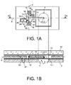
- FIGS 1A and 1B are views from above and in section respectively of an exemplary embodiment of a pressure sensor, comprising a substrate 2, a membrane 4 suspended on the substrate, the membrane being such that it deforms under the action of a pressure difference on both sides, detection means 6 of the deformation of the membrane located on the substrate and means capable of transmitting the deformation of the membrane 4 to the detection means 6.
- the membrane 4 is subjected on one of its faces 4.1 to the pressure P that it is desired to measure, in the representation of the Figure 1B it is the underside of the membrane.
- the other face 4.2 is subject to a reference pressure which is made in a cavity 10 formed between the membrane 4 and a cover 12.
- the vacuum is formed in the cavity 10.
- the cover 12 is sealed on the substrate 2 is by means of a sealing bead 13 or by direct sealing, of the cordless type.
- the membrane 4 is in the form of a disk (in dotted lines on the Figure 1A ) but it could have any other shape, such as a square, hexagonal shape ....
- the means for transmitting the deformation of the membrane 4 to the detection means 6 are formed by an arm 14 with a longitudinal axis X, mounted to rotate with respect to the substrate at a first longitudinal end 14.1, the axis of rotation Y is substantially parallel to the membrane and the plane of the substrate.
- the arm 14 is secured in movement of the membrane at its second longitudinal end 14.2.
- the arm is dimensionally stable, i.e. it has a rigidity greater than at least 10 to 100 times the rigidity of the membrane and transmission means.
- the arm is suspended above the membrane, ie it is arranged above the membrane and a space exists between the arm 14 and the membrane, the only contact between the arm and the membrane is at the second longitudinal end 14.2 of the arm 14.
- the arm has, in the example shown, the shape of a rigid beam with rectangular section.
- the beam could alternatively have a trapezoidal shape.
- the second longitudinal end 14.2 of the arm 14 is integral with the membrane at or near the zone having the maximum deformation.
- the movement of the arm around its axis of rotation Y seen by the detection means is then maximum and the sensitivity of the sensor is then optimized.
- portion of the arm 14 secured to the membrane could be another part than the second end longitudinal 14.2, between the first 14.1 and the second 14.2 longitudinal end.
- the detection means 6 are arranged on the substrate so that they detect the displacement of the first longitudinal end 14.1 of the arm, this displacement being proportional to the amplitude of deformation of the membrane 4.
- the arm 14 forming a lever arm the stress seen by the detection means 6 is amplified with respect to the deformation of the membrane.
- the lever arm increases the stress exerted on the gauges but decreases the amplitude of deformation with respect to the amplitude of deformation of the membrane due to the law of preservation of the moments.
- the y-axis pivot connection is formed by a Y-axis beam 18 biased about the Y axis.
- the beam is anchored at each of its ends on the substrate.
- the beam 18 will be designated "torsion axis 18".
- this beam 18 comprises a rigid portion in flexion along the X axis to transmit all the stress on which the gauges are fixed, and a portion forming a torsion axis at its ends also rigid in flexion along the axis X of the constraint .
- the rotational joint may be formed by one or more beams 118 biased in bending axis parallel to that of the arm 14.
- the beam 118 in a state of flexing.
- a flexible connection along the X axis and rigid along the Z axis between the membrane and the transmission arm 14 is produced in a manner similar to the embodiment of the figure 3 .
- the transmission element has substantially the shape of a U, the bottom of the U being secured to the membrane 4 and the free ends of the two branches forming the first ends and urge the detection means.
- the detection means 6 are formed by two suspended strain gages 16 each fixed by a first end 16.1 on the torsion axis 18 and by a second end 16.2 to an anchor pad 20 to the substrate 2.
- the stress amplified by the arm 14 then applies to the longitudinal ends of the gauge.
- the stiffness of the beam 18 in the transverse direction relative to the axis Y is preferably at least 10 times greater than the stiffness in compression of the gauge or gauges, which makes it possible to avoid a deformation of the beam and a reduction deformation transmitted to the beam.
- the gauges 16 are disposed on either side of the axis of rotation and the arm 14.
- the detection means could comprise only one strain gauge.
- the implementation of two strain gauges makes it possible to perform differential measurements, making the device less sensitive thermally.
- the electrical contact 24 is formed on the rear face of the substrate 2, on the deformable membrane side, and can be used to polarize the gauge.
- the contact is connected to the gauge by means of a through or through contact or TSV (Through Silicon Vias in English terminology) and via the anchor pad 20.
- the strain gauges may be of piezoelectric material or of piezoresistive material.
- the gauges are oriented so that their sensitive axis is substantially parallel to the link arm and therefore it is substantially orthogonal to the axis of rotation of the link arm. Furthermore, the neutral line of each gauge is disposed above or below the axis of rotation of the transmission arm. For this, the gauges may have a lower thickness to that of the torsion beam and / or flexion. For example, to obtain this lower thickness from the same layers, it is possible to deposit an excess thickness on said beams.
- the membrane When a pressure difference appears between the face 4.2 of the membrane 4 which is in contact with the inside of the cavity 10, which is at the reference pressure, and the face 4.1 of the membrane, which is in contact with the environment whose pressure is to be measured, the membrane is deformed.
- the deformation is either towards the inside of the cavity or towards the outside of the cavity as a function of the value of the pressure to be measured with respect to the reference pressure.
- This deformation induces a force on the arm 14 secured to the membrane, which has the effect of generating a stress in the strain gauges 16.
- This stress is amplified because of the arm and its pivot about the Y axis.
- the strain experienced by the gauges 16 is then measured, for example, by measuring the variation in the electrical resistance of the gauges in the case of piezoresistive gauges. These measurements then make it possible to determine the pressure difference seen by the membrane and the pressure of the environment.
- the amplification of the constraint by the lever arm will be all the more important that the length of the arm between the point of application of the force by the membrane and the axis of rotation Y will be large, that the axis of rotation will be close to the point of application of the constraint on the gauge.
- the stress will be even higher as the section of the gauge (thickness, width) will be small.
- the sensitivity of the sensor is increased. It is therefore possible to offer more efficient sensors or to reduce the size of the sensors, for example by reducing the surface of the membrane, while maintaining the same performance.
- the detection means 6 ' are of the capacitive type, ie the detection is obtained by measuring a capacitance variation of a capacitor 25.
- the detection means 6' comprise a fixed electrode 26 located on the substrate 2 and a moving electrode 28 is secured to the arm 14, and facing the fixed electrode 26.
- the movable electrode 28 is fixed to the first end 14.1 of the arm 14.
- the fixed electrode 26 is connected to a contact 30 and the moving electrode is connected in electrical contact formed on one of the anchoring studs of the torsion axis 18.
- the arm 14 When the membrane 4 is deformed, the arm 14 carries with it the moving electrode 28, which moves relative to the fixed electrode 26.
- the gap distance between the two electrodes 26, 28 varies, this variation is representative of the deformation of the membrane 4 and therefore the pressure of the environment.
- the displacement of the movable electrode 28 can be amplified relative to that of the membrane 4.
- the capacity variation is increased.
- the sensitivity of the pressure sensor is thus increased.
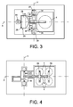
- FIG. 3 an exemplary embodiment of a capacitive detection pressure sensor can be seen, allowing a differential measurement.
- This sensor differs from that of Figures 2A and 2B in that it comprises at least one additional capacitance capacitor 32 to enable measurement of a second capacitance variation.
- there are two additional capacitors 32 so the movable electrodes 34 are located between the torsion axis 18 and the membrane 4 and are connected to the torsion axis 18 on either side of the arm 14.
- Fixed electrodes 36 (shown in dotted lines) are located opposite the movable electrodes 34 on the substrate 2. The fixed electrodes 36 are connected to contact pads 37 and 30.
- the distance between the torsion axis 18 and the electrode 28 is the same as that between the torsion axis is the electrodes 34 so that they see the same amplification.
- the surface of the electrode 28 is chosen equal to the sum of the surfaces of the two electrodes 34.
- the pressure sensor of the Figures 1A and 1B comprising several membranes 4, the arm 14 being connected to each of the membranes 4.
- the arm comprises two parallel transverse elements 39, extending from arm 14 and connected in the vicinity of their ends to a membrane 4.
- the deformations of the four membranes 4 apply a force on the arm 14, and the total surface of the four membranes being greater than that of a single membrane, the force applied on the arm and thus on the gauges is increased.
- This embodiment is particularly interesting for strain gage sensors, such as piezoresistive or resonant gauges.
- the sensor comprises stop means 38 disposed between the membrane 4 and the cover.
- the abutment 38 serves to limit the displacement of the membrane 4, and therefore that of the arm 14, to protect the gauges 16. Indeed, in the event of a pressure shock, the pressure seen by the membrane may be outside the expected measurement range. at the construction, and the membrane 4 via the arm 14 can apply a stress greater than the stress that can withstand the gauge or the gauges 16.
- the stop is above the arm and directly forms a stop for the arm, for example in the case where the stop is made directly by the cover 12 or on the cover above the arm.
- An electrical contact 40 can be added to the anchor pad of the stop to control the potential of the stop, for example the stop could be at the potential of the membrane, which avoids the risk of short circuit in case of contact of the membrane on the abutment and the risk of parasitic electrostatic attraction of the membrane towards the abutment.
- the membrane 4 ' has a locally increased rigidity in order to reduce the deformation of the membrane 4 in favor of the stress applied on the arm 14 and on the gauge or gauges 16.
- the membrane 4 is stiffened locally by adding radial extra thicknesses 41 on the membrane 4, having a structure similar to umbrella whales.
- a honeycomb structure may also be suitable or any other means increasing the rigidity of the membrane.
- the level of stiffening is chosen to avoid making the sensor too sensitive to acceleration.
- the counterweight 42 is fixed on the first end 14.1 of the arm 14.
- the counterweight 42 has the effect of moving the center of gravity of the assembly of membrane 4 and arm 14 to which is added the counterweight 42 to the axis of rotation Y, so that it is the most possible porch of the axis of rotation Y, even on the axis of rotation Y.
- the pressure sensor is then less sensitive or insensitive to off-plane acceleration, i.e. acceleration tending to deflect the membrane.
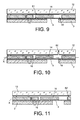
- the detection means 6 comprise a resonator 44 suspended between the torsion axis 18 and an anchor pad 46 carrying an electrical contact, excitation means 48 of the resonator 44 and detection means 50 of the variation of the resonance frequency of the resonator 44, ie its resonance frequency.
- the excitation means 48 and detection 50 are for example capacitive type and are formed by the electrodes.
- the resonator may be piezoelectric. The excitation and the detection are then obtained by electrodes arranged on the resonator. It is also possible to provide a second resonator on the other side of the Y axis.
- the resonator has a reduced thickness with respect to the torsion axis 18 in order to be sensitive to the out-of-plane movement of the arm 14.
- this sensor is as follows: when the membrane 4 is deformed, it applies a stress to the arm 14 which transmits it to the resonator 44. This is excited by the excitation means 48 and is vibrated at the resonance . Due to the stress applied to it, its resonance frequency varies, this variation is then measured by the detection means 50. It is then possible to go back to the deformation of the membrane and thus to the pressure of the environment.
- the absolute pressure sensor comprising a layer of getter material 51 disposed in the cavity 10, for example deposited on the face of the hood located at the inside of the cavity 10.
- This layer 51 makes it possible to stabilize and / or improve the vacuum in the cavity 10, which improves the reliability and the performance of the sensor.
- a vent 52 is preferably made directly through the cover 12 for example by etching or laser drilling.
- vent 52 ' is formed laterally between the cover 12 and the substrate 4, for example through the sealing bead.
- These devices can form a relative pressure sensor or microphone.
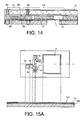
- FIGS 12A and 12B we can see yet another variant embodiment of the pressure sensor of Figures 1A and 1B , in which the lower face 4.2 of the membrane 4 is brought into contact with the pressure to be measured by a duct 54 formed in the substrate parallel to the plane of the substrate and a duct 55 formed through the hood 12 perpendicular to the plane of the hood and opening on the front of the sensor.
- the conduit 54 may be made at the time of the realization of the chip, for example by a cutting line produced by means of a saw or by laser.
- the encapsulation of the inertial sensor IC is obtained by producing a cavity 58 distinct from the cavity 10 of the pressure sensor, a sealing bead 60 separating them.
- a cavity 58 distinct from the cavity 10 of the pressure sensor, a sealing bead 60 separating them.
- a closed cavity it is conceivable to make only one cavity for the two sensors CP and CI.
- the structure of the sensor is close to that of the sensor of the Figure 1A .
- the detection of the deformation of the membrane is obtained by means of piezoelectric gauges.
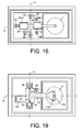
- the pressure sensor comprises means for the compensation of the static pressure and / or the self-calibration and / or the self-test of the pressure sensor.
- the sensor comprises two pairs of capacitive actuating electrodes 66.1, 66.2, one 66.1 being located between the axis of rotation Y and the connection with the membrane 4 and the other 66.2 being situated on the other side of the Y axis.
- An electrode, said upper electrode, of each pair is located on the arm and the other electrode, said lower electrode, of each pair is located on the substrate but electrically isolated from the substrate.
- the lower electrodes are shown in FIG. dashed.
- the upper electrodes of each pair are electrically connected via the amplification arm and the pad 19.
- the contact pad 68 ensures the activation of the lower electrode of the pair 66.1 and the contact pad 70 ensures the activation of the lower electrode of the pair 66.2.
- the activation of the electrodes 66.1 makes it possible to move the arm downwards and the activation of the electrodes 66.2 makes it possible to move the arm upwards and thus to act on the deformation of the membrane.
- the activation of the electrodes 66.1 causes a pivoting of the arm 14 in the clockwise direction and a displacement of the membrane towards the substrate 2, which makes it possible to cancel all or part of the deformation of the membrane resulting from this static pressure, for measure only the pressure variations around this static pressure.
- Activation of the electrodes 66.2 causes pivoting of the arm counterclockwise and displacement of the membrane away from the substrate 2.
- Activation of the actuation electrodes 66.2 makes it possible to carry out self-tests.
- the correct operation of the sensor can then be verified by deforming the membrane 4 upwards by the electrostatic actuation means by means of the pair of electrodes 66.2 and verifying that the detection means are sensitive to this induced deformation.
- the activation of the actuation electrodes 66.2 also makes it possible to carry out a self-calibration.
- the pressure sensor is calibrated by applying a voltage between the actuating electrodes 66.2. known, inducing a deformation of the membrane that "simulates" a reference pressure, thus allowing to reset the output signal of the sensor.
- the detection means piezoresistive gauges for example, are used to measure the pressure variations around this compensated static pressure.
- a pressure sensor comprising only the means of self-test and / or calibration or the means for canceling the static pressure is not outside the scope of the present invention.
- Electrodes can be used to enslave the arm and the membrane in position, in particular in the case of a capacitive detection.
- the pair of electrodes 66.1 is located opposite the axis of rotation relative to the membrane 4.
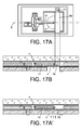
- FIG 17 another embodiment of a pressure sensor comprising means for the compensation of the static pressure and / or the self-calibration and / or the self-test of the pressure sensor can be seen.
- the actuation electrode is such that it can act directly on the membrane.
- the actuation electrode 69 is located above the membrane, the latter being made in the MEMS layer.
- the electrode 69 has the shape of a beam extending perpendicularly to the longitudinal axis X.
- the beam is embedded at one end, the recess 71 also forming an electrical contact .
- the electrode 69 may extend over the entire surface of the membrane outside the transmission beam).
- the actuating electrode 69 is embedded at its two longitudinal ends.
- the actuation electrode 70 ' may be located below the membrane 14 using a portion of the substrate. For this, the section of the inlet opening pressure is reduced, which allows to have a part of the substrate facing the membrane. This example is represented on the FIG. 17A ' .
- a space 72 is provided between the membrane and the end of the lever arm 14 to allow deformation of the membrane without action on the arm 14 in an initial phase of deformation of the membrane.
- the space 72 is determined as a function of the proportion of static pressure to be compensated. For example, it may be desired to compensate for 90% of this static pressure, the gauges then see a stress only above a pressure applied above 90% of the static pressure to be compensated.
- the resolution of the pressure sensor can be increased by a factor of 5 to 10.
- the pressure sensor may comprise, in addition to the space 72, a flexible mechanical connection between the membrane and the amplification arm.
- This flexible connection is sized to transmit virtually no strain to the gauges as long as the membrane is not exposed. in direct mechanical contact with the amplification arm 14.
- This flexible mechanical connection allows the membrane and the arm 14 to be at the same electrical potential whatever the pressure.
- the flexible connection is for example formed by a flexible beam or a spring.
- a pressure sensor advantageously comprising a flexible joint 115 between the membrane 4 and the arm 14.
- This joint is of spring type or bending beam.
- a flexural beam 116 which makes it possible to fully transmit the force along the Z axis induced by the deformation of the membrane, while limiting the parasitic force along the X axis, ie along the axis of the arm 14 due to this deformation.
- This link has some flexibility along the X axis so as not to hinder the deformation of the membrane, and a certain rigidity to transmit all the deformation of the membrane to the arm.
- lever arms each transmitting the deformation to separate detection means arranged around the membrane, the lever arms extending radially.
- the membrane and the detection means are cut off, which makes it possible to optimize them separately.
- the amplification of the stress in the case of a resonant sensor or strain gage detection and the amplification of the displacement in the case of a sensor with capacitive detection brings a gain in significant sensitivity, the sensor pressure can be made more efficient or its size can be reduced.
- differential pressure sensors are technologically simplified, both in the case of the use of piezoresistive detection means, capacitive or resonant.
- This differential measurement makes it possible to increase the signal-to-noise ratio and to limit the thermal sensitivity of the sensor.
- the technology for producing pressure sensors according to the invention being very close to the manufacturing technologies of MEMS and / or NEMS inertial sensors in surface technology, it is possible to pool a large part of the existing processes. It is then also possible to co-integrate these different sensors as shown on the figures 13 and 14 .
- the gauge may be of nanometric section, which provides a higher concentration of stress and offers increased sensitivity.
- the gauges are protected from the outside by the hood.
- the volume of the cavity 10 does not intervene in the electrostatic gap between the membrane and the fixed electrode. We can then make a cavity 10 having a large volume under vacuum, which allows to obtain a reference vacuum may be more stable and more advanced than in conventional sensors.
- the electrostatic gap between the membrane and the fixed electrode is well controlled because it is defined by a sacrificial layer.
- the vacuum closure of the cavity is performed during sealing, for example eutectic, anodic, SDB (Silicon Direct Bonding), or direct sealing.
- sealing for example eutectic, anodic, SDB (Silicon Direct Bonding), or direct sealing.
- the seal uses the surface forces to ensure the adhesion of the two substrates ..., this type of closure makes it possible to obtain a good quality of vacuum, which is more reliable than that obtained by means of a plugging by deposit.
- the production method makes it possible to insert a getter material in the vacuum cavity 10, which is particularly advantageous in the case where it is desired to have a reference vacuum which is pushed and stable over time, in particular to achieve a sensor sensitive to low pressures.
- the recovery of the electrical contacts of the membrane and the substrate can be simplified, by using a technology of the type TSV (Through Silicon Via) which integrates with the process of realization by surface technology of the sensitive part of the sensor, and allowing a recovery of the contacts either by the front face or by the rear face of the sensor.
- TSV Through Silicon Via
- SOI 100 substrate Silicon on Insulator
- BOX Boried Oxide
- active silicon 0.2 microns thick
- the second layer can be obtained by epitaxy or deposition of silicon or SiGe.
- the upper silicon layer 102 has a thickness of between a few tens of nm and a few microns.
- the oxide layer of the SOI substrate is designated 101.
- a lithography step is carried out in order to define the strain gauges, the torsion axis, the contour of the membrane 4, the contour of the contact and embedding zones of the gauges and of the torsion axis and the opening of the resumption of contact on the rear face.
- openings are made at the contacts of the embedding studs, which makes it possible to raise the electrical contacts between the substrate 100 and the active layer 102 during the epitaxy step, following the etching of the oxide in these openings
- the etch layer is then etched with the oxide layer 101. The remaining resin is removed.
- a layer of SiO 2 106 is deposited.
- a lithography is then carried out to protect the strain gauges, the membrane 4, and to define the opening of the contact zones and the contact pads. embedding of the gauges and the torsion axis, and the opening of the anchoring zone 64 of the arm 14 on the membrane 4.
- An oxide etching of the layers 101 and 106 then takes place with a stop on the silicon of the layer 102 and on the silicon of the SOI substrate. The remaining resin is removed. The element thus obtained is visible on the figure 15B .
- a layer 108 of silicon, monocrystalline or polycrystalline is deposited, for example by epitaxy, typically having a thickness of between 1 ⁇ m and a few tens of ⁇ m. Mechanical-chemical polishing of the layer 108 can be achieved. The element obtained is visible on the figure 15C .
- a lithography is performed on the layer 108 in order to define the opening area of the membrane 4, and the opening area of the gauges 16, and to define the arm 14 and the isolation zones. contacts.
- the layer 108 is etched with the SiO 2 layer 106 and 101. The remaining resin is removed. The element obtained is visible on the figure 15D .
- the arm 14 is released, the torsion axis and the gauges by etching, for example by means of hydrofluoric acid vapor.
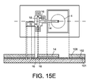
- the layer 106 is entirely etched as well as part of the SiO 2 layer of the SOI substrate.
- the membrane 4 is not yet released. The element obtained is visible on the figure 15E .
- vacuum sealing of the cover is carried out by means of a bead 13.
- the seal may for example be of the eutectic, SDB or anodic type in the case of a glass cover, ie cordless, the seal being obtained by direct adhesion of both surfaces 12 and 108.
- a cavity is first made in the cover before sealing, at least above the moving parts.
- the hood may have been previously prepared.
- the preparation of the cover may include the steps of making a cavity, the deposit of getter, making electrical routes or even an electronic (CMOS co-integration) in the case of eutectic sealing, ...
- the sealed cavity 10 around the membrane is then formed.
- the substrate is then thinned, for example by rear-face abrasion or back-grinding and chemical-mechanical polishing.
- the element obtained is visible on the figure 15F .
- a metal layer is deposited on the rear face of the substrate in order to make the contact on the rear face. Then, a lithography is performed on this layer to delimit the backface contact and finally an etching of the metal layer is performed. The resin on the remaining metal layer is removed. A new lithography is performed on the rear face to delimit the zone of isolation of the contacts and the opening of the membrane 4, as well as etching of the substrate on the rear face, for example by deep etching by reactive ions or DRIE ("deep reactive-ion etching "in English) with a stop on the oxide layer 101 of the SOI substrate. The remaining resin is removed. The element obtained is visible on the figure 15G .
- Thickness values are given by way of example only.
- the sacrificial layers are between a few tens of nm and a few microns
- the active layers such as Si, SiGe, ... are between a few tens of nm and a few tens of microns. .
- the pressure measuring device can be used in all fields where a pressure measurement is required, for example in the automotive, medical, avionics, and also for consumer applications.
- this sensor can be used to make a microphone for consumer applications, such as in mobile phones, or the medical field for making hearing aids, etc.
Abstract
Description
La présente invention se rapporte à des capteurs de pression présentant une sensibilité optimisée, les capteurs sont du type MEMS (Microelectromechanical Systems) ou systèmes microélectromécaniques et/ou NEMS (Nanoelectromechanical Systems) ou systèmes nanoélectromécaniques.The present invention relates to pressure sensors having an optimized sensitivity, the sensors are MEMS (Microelectromechanical Systems) or microelectromechanical systems and / or NEMS (Nanoelectromechanical Systems) or nanoelectromechanical systems.
Un capteur de pression est classiquement constitué d'une membrane encastrée apte à se déformer sous une différence de pression qui s'exerce entre ses deux faces. Dans le cas d'un capteur de pression absolue, la membrane sépare un volume de référence sous vide du milieu extérieur à mesurer. La membrane se déforme alors plus où moins en fonction de la pression extérieure.A pressure sensor is conventionally constituted by a built-in diaphragm capable of deforming under a pressure difference exerted between its two faces. In the case of an absolute pressure sensor, the membrane separates a reference volume under vacuum from the external medium to be measured. The membrane then deforms more or less depending on the external pressure.
La déformation de la membrane peut être détectée et mesurée par différentes techniques.The deformation of the membrane can be detected and measured by different techniques.
L'une d'elles est de type capacitif. La déflexion de la membrane est déterminée en mesurant la variation de capacité du condensateur formé entre la membrane et une contre-électrode fixe en regard. La membrane est réalisée sur un premier substrat et la contre-électrode est formée sur un deuxième substrat, les deux substrats sont ensuite scellés sous vide. La distance d'entrefer du condensateur est donc déterminée par l'entrefer de scellement, qu'il est difficile de maîtriser parfaitement.One of them is of the capacitive type. The deflection of the membrane is determined by measuring the variation in capacitance of the capacitor formed between the membrane and a fixed counter-electrode opposite. The membrane is made on a first substrate and the counter-electrode is formed on a second substrate, the two substrates are then sealed under vacuum. The gap distance of the capacitor is therefore determined by the sealing gap, which is difficult to master perfectly.
Une autre technique de détection met en oeuvre des jauges piézorésistives, les jauges sont alors disposées directement sur la membrane, celles-ci sont donc déformées directement par la déformation de la membrane.Another detection technique uses piezoresistive gauges, the gauges are then arranged directly on the membrane, these are therefore deformed directly by the deformation of the membrane.
Une autre technique de détection met en oeuvre un résonateur, par exemple de type poutre suspendue ou diapason. Cette technique consiste à mesurer une variation de la fréquence de résonance du résonateur. La déflexion de la membrane sous l'effet de la pression génère une contrainte sur un résonateur fixé directement sur la membrane, qui a pour effet de modifier sa fréquence de résonance. La mesure du décalage en fréquence permet par conséquent de remonter à la pression.Another detection technique uses a resonator, for example of suspended beam type or tuning fork. This technique consists of measure a variation of the resonance frequency of the resonator. The deflection of the membrane under the effect of the pressure generates a stress on a resonator fixed directly on the membrane, which has the effect of modifying its resonance frequency. Measuring the frequency offset therefore makes it possible to go back to the pressure.
Les capteurs de pression quelle que soit la technique de détection utilisée n'offre pas une sensibilité optimisée. En outre, ils ne permettent pas de réaliser facilement de détection différentielle.Pressure sensors regardless of the detection technique used does not offer optimized sensitivity. In addition, they do not make it easy to perform differential detection.
De plus d'un point de vue procédé de réalisation, la technologie mise en oeuvre pour réaliser les capteurs de pression MEMS est en générale très éloignée de celle utilisée pour la fabrication des capteurs inertiels en technologie de surface. Il en résulte donc qu'il y a peu de co-intégration possible de ces deux types de capteurs.In addition to a method of implementation, the technology used to make the MEMS pressure sensors is generally far removed from that used for the manufacture of inertial sensors in surface technology. As a result, there is little possible co-integration of these two types of sensors.
Le document
C'est par conséquent un but de la présente invention d'offrir un dispositif de mesure de pression type MEMS et/ou NEMS offrant une sensibilité optimisée.It is therefore an object of the present invention to provide a MEMS and / or NEMS type pressure measuring device with optimized sensitivity.
Le but précédemment énoncé est atteint par un dispositif de mesure de pression MEMS et/ou NEMS comprenant une membrane définissant avec un substrat une cavité et un élément de transmission de la déformation de la membrane monté mobile en rotation au niveau d'une première extrémité sur le substrat autour d'un axe sensiblement parallèle à la membrane et rendu solidaire de la membrane au niveau d'une deuxième extrémité et un ou des détecteurs du déplacement en rotation de l'élément de transmission disposés au niveau de la première extrémité de l'élément de transmission, ce ou ces détecteurs pouvant être de type jauge de contrainte suspendue (i.e. une jauge suspendue dans l'espace par ses deux extrémités), de type capacitif ou de type résonant. L'élément de transmission forme un bras de levier, l'effet sur le ou les détecteurs est ainsi amplifiée, ce qui permet d'optimiser la sensibilité du capteur de pression. Le capteur ainsi réalisé peut, soit offrir des performances améliorées, soit une taille réduite à performance égale.The previously stated purpose is achieved by a MEMS and / or NEMS pressure measuring device comprising a membrane defining with a substrate a cavity and a deformation transmitting member of the rotatably mounted membrane at a first end on the substrate around an axis substantially parallel to the membrane and rendered integral with the membrane at a second end and one or detectors of the rotational displacement of the transmission element disposed at the first end of the transmission element, this or these detectors being able to be of the suspended stress (ie a gauge suspended in space by its two ends), capacitive type or resonant type. The transmission element forms a lever arm, the effect on the detector (s) is thus amplified, which optimizes the sensitivity of the pressure sensor. The sensor thus produced can either offer improved performance or a reduced size with equal performance.
En outre, la membrane et le ou les détecteurs sont découplés, le ou les détecteurs n'étant pas directement sur la membrane, il devient alors possible d'optimiser la membrane et le ou les détecteurs séparément.In addition, the membrane and the detector (s) are decoupled, the detector (s) not being directly on the membrane, it then becomes possible to optimize the membrane and the detector (s) separately.
II est de plus relativement aisé de faire des mesures différentielles quel que soit le type de détecteur utilisé.It is also relatively easy to make differential measurements regardless of the type of detector used.
En d'autres termes, on utilise un bras de levier qui permet de transmettre et d'amplifier le signal émis la membrane au(x) détecteur(s) et de découpler géographiquement et mécaniquement la membrane et le ou les détecteurs.In other words, a lever arm is used which makes it possible to transmit and amplify the signal emitted by the membrane to the detector (s) and to decouple the membrane and the detector (s) geographically and mechanically.
Le capteur de pression selon l'invention peut alors être réalisé avec les technologies de fabrication de capteurs inertiels MEMS ou NEMS en technologie de surface, il devient alors aisé d'associer différents types de capteurs sur un même substrat.The pressure sensor according to the invention can then be made with MEMS or NEMS inertial sensor manufacturing technologies in surface technology, it then becomes easy to associate different types of sensors on the same substrate.
La présente invention a alors pour objet un dispositif de mesure de pression MEMS et/ou NEMS comportant au moins une membrane déformable suspendue sur un substrat, une des faces de la membrane étant destinée à être soumise à la pression à mesurer, des moyens de détection de la déformation de la membrane, lesdits moyens de détection étant disposés au moins partiellement sur le substrat et des moyens de transmission de la déformation de la membrane, aux moyens de détection, lesdits moyens de transmission étant indéformables, lesdits moyens de transmission étant suspendu au dessus de la membrane, lesdits moyens de transmission étant articulés en rotation sur le substrat autour d'un axe sensiblement parallèle au plan de la membrane et étant disposés en regard d'une face de la membrane opposée à la face destinée à être soumise à la pression à mesurer de telle sorte qu'au moins au-delà d'une pression donnée, lesdits moyens de transmission et la membrane soient solidaires en déplacement et de sorte que les moyens de transmission transmettent aux moyens de détection, de manière amplifiée, la déformation ou la contrainte issue de la déformation de la membrane.The subject of the present invention is therefore a device for measuring pressure MEMS and / or NEMS comprising at least one deformable membrane suspended on a substrate, one of the faces of the membrane being intended to be subjected to the pressure to be measured, detection means deformation of the membrane, said detection means being arranged at least partially on the substrate and means for transmitting the deformation of the membrane, to the detection means, said transmission means being dimensionally stable, said transmission means being suspended above the membrane, said transmission means being rotatably articulated on the substrate about an axis substantially parallel to the plane of the membrane and being arranged opposite a face of the membrane opposite to the face intended to be subjected to the pressure to be measured so that at least beyond a given pressure, said transmission means and the membrane are integral in displacement and so that the transmission means transmit to the detection means , amplified manner, the deformation or stress resulting from the deformation of the membrane.
On entend par "moyens de transmission indéformable", des moyens de transmission, par exemple une poutre, présentant une raideur supérieure à au moins 10 à 100 fois la raideur de la membrane et des moyens de détection.The term "indeformable transmission means" means transmission means, for example a beam, having a stiffness greater than at least 10 to 100 times the stiffness of the membrane and detection means.
En outre, le déplacement de la membrane correspond à sa déformation sous l'effet de la pression.In addition, the displacement of the membrane corresponds to its deformation under the effect of pressure.
On entend par rotation aussi bien un mouvement du bras issu d'une torsion, obtenu par exemple par une poutre sollicitée en torsion, qu'un mouvement du bras issu d'une flexion, par exemple obtenu par une poutre de flexion, une flexion de la poutre décrivant une partie de la rotation dudit bras.By rotation is meant both a movement of the arm resulting from a twisting, obtained for example by a torsionally stressed beam, a movement of the arm resulting from a bending, for example obtained by a bending beam, a bending of the beam describing part of the rotation of said arm.
Les moyens de transmission sont solidaires en mouvement de la membrane au moins au-delà de la pression donnée, avantageusement dans une zone de déformation maximale de la membrane.The transmission means are integral in motion of the membrane at least beyond the given pressure, preferably in a zone of maximum deformation of the membrane.
Par exemple, les moyens de transmission comportent au moins un bras longitudinal comportant au moins une première extrémité au niveau de laquelle se situent les moyens de détection et une deuxième extrémité au niveau de laquelle le bras est solidaire en déplacement de la membrane au moins au-delà de la pression donnée.For example, the transmission means comprise at least one longitudinal arm comprising at least a first end at which the detection means are located and a second end at which the arm is secured in displacement of the membrane at least at beyond the given pressure.
Dans un mode de réalisation, la deuxième extrémité du bras est solidaire mécaniquement de la membrane quelle que soit la valeur de la pression.In one embodiment, the second end of the arm is mechanically secured to the membrane regardless of the value of the pressure.
Dans un autre mode de réalisation, un espace est prévu entre la deuxième extrémité du bras et la membrane pour une pression inférieure à la pression donnée. De préférence, le bras est relié électriquement à la membrane.In another embodiment, a space is provided between the second end of the arm and the membrane for a pressure lower than the given pressure. Preferably, the arm is electrically connected to the membrane.
Par exemple, la pression donnée est inférieure ou égale à la pression minimale à mesurer.For example, the given pressure is less than or equal to the minimum pressure to be measured.
Dans un exemple de réalisation, le bras longitudinal est solidaire de la membrane par l'intermédiaire d'une liaison souple suivant l'axe longitudinal du bras et rigide suivant un axe de déformation de la membrane.In an exemplary embodiment, the longitudinal arm is secured to the membrane by means of a flexible connection along the longitudinal axis of the arm and rigid along an axis of deformation of the membrane.
Selon un mode de réalisation, les moyens de transmission comportent moins une poutre de torsion reliant la première extrémité du bras longitudinal aux moyens de détection, orthogonale au bras longitudinal, l'axe de rotation étant formé par ladite poutre de torsion qui est ancrée d'une part à la première extrémité du bras et d'autre part, au substrat et aux moyens de détection.According to one embodiment, the transmission means comprise less a torsion beam connecting the first end of the longitudinal arm to the detection means, orthogonal to the longitudinal arm, the axis of rotation being formed by said torsion beam which is anchored to a part at the first end of the arm and secondly, the substrate and the detection means.
La poutre de torsion peut présenter une section variable. Avantageusement, la section de la poutre de torsion est plus grande au voisinage des ancrages aux des moyens de détection qu'au voisinage des ancrages au substrat, ce qui permet de rigidifier lesdits ancrages.The torsion beam may have a variable section. Advantageously, the section of the torsion beam is greater in the vicinity of the anchors to the detection means than in the vicinity of the anchors to the substrate, which makes it possible to stiffen said anchorages.
Dans un autre mode de réalisation, les moyens de transmission comportent au moins une poutre de flexion sensiblement parallèle au bras longitudinal, l'axe de flexion étant formé par ladite poutre de flexion qui est ancrée d'une part au bras longitudinal et d'autre part au substrat. Avantageusement, la section de la poutre de flexion est inférieure à celle du bras de transmission.In another embodiment, the transmission means comprise at least one bending beam substantially parallel to the longitudinal arm, the bending axis being formed by said bending beam which is anchored on the one hand to the longitudinal arm and on the other hand part to the substrate. Advantageously, the section of the bending beam is smaller than that of the transmission arm.
Dans un exemple de réalisation particulièrement intéressant, le bras longitudinal présente un motif en « U », ledit motif comportant deux extrémités correspondant aux dites premières extrémités du bras, ces dernières étant reliées respectivement aux moyens de détection par l'intermédiaires de poutres d'extension latérales.In a particularly interesting embodiment, the longitudinal arm has a "U" pattern, said pattern having two ends corresponding to said first ends of the arm, the latter being respectively connected to the detection means by means of extension beams. side.
On pourrait envisager que la poutre de flexion comporte une seule première extrémité munie d'une seule poutre d'extension latéraleIt could be envisaged that the bending beam has a single end provided with a single beam of lateral extension
Selon une caractéristique additionnelle, le dispositif peut comporter des moyens pour rigidifier la membrane. Les moyens de rigidification forment par exemple des zones de surépaisseur sur la membrane, par exemple disposées radialement ou en nid d'abeille.According to an additional characteristic, the device may comprise means for stiffening the membrane. The stiffening means form, for example, zones of excess thickness on the membrane, for example arranged radially or in honeycomb.
Selon une autre caractéristique additionnelle, le dispositif peut comporter un contrepoids fixé sur le bras au niveau de la première extrémité du bras.According to another additional feature, the device may comprise a counterweight attached to the arm at the first end of the arm.
Selon une autre caractéristique additionnelle, le dispositif peut comporter plusieurs membranes déformables soumises à la même pression, les moyens de transmission étant solidaires de toutes les membranes.According to another additional characteristic, the device may comprise several deformable membranes subjected to the same pressure, the transmission means being integral with all the membranes.
Selon une autre caractéristique additionnelle, le dispositif peut comporter une butée disposée en regard de la membrane à l'opposé de la face de la membrane soumise à la pression de sorte à limiter sa déformation.According to another additional characteristic, the device may comprise an abutment disposed facing the membrane opposite the face of the membrane subjected to the pressure so as to limit its deformation.
Selon une autre caractéristique additionnelle, le dispositif peut comporter un capot sur le substrat et définissant une cavité autour de la membrane à l'opposé de la face soumise à la pression à mesurer.According to another additional characteristic, the device may comprise a cover on the substrate and defining a cavity around the membrane opposite the face subjected to the pressure to be measured.
Par exemple, la mise en communication de la face de la membrane soumise à la pression à mesurer et l'environnement dont la pression est à mesurer est réalisée à travers le capot et/ou entre le capot et le substrat.For example, placing in communication the face of the membrane subjected to the pressure to be measured and the environment whose pressure is to be measured is achieved through the cover and / or between the cover and the substrate.
Selon un mode de réalisation, les moyens de détection comportent au moins une jauge de contrainte suspendue reliée par une extrémité au substrat par un plot d'ancrage et par une autre extrémité à la poutre de torsion ou au bras de transmission.According to one embodiment, the detection means comprise at least one suspended strain gauge connected at one end to the substrate by an anchor pad and at another end to the torsion beam or the transmission arm.
Par exemple, la jauge de contrainte est choisie parmi une jauge piézorésistive, une jauge piézoélectrique et une jauge résonante dite résonateur.For example, the strain gauge is selected from a piezoresistive gauge, a piezoelectric gauge and a so-called resonator resonator gauge.
Dans un exemple de réalisation, les moyens de détection peuvent comporter deux jauges de contrainte fixées par une extrémité sur la poutre de torsion de part et d'autre de celle-ci et par une autre extrémité au substrat par des plots d'ancrage. Avantageusement ces jauges sont disposées symétriquement par rapport au bras de transmission. En variante, les jauges peuvent être également disposées du même côté.In an exemplary embodiment, the detection means may comprise two strain gauges fixed by one end on the torsion beam on either side thereof and by another end to the substrate by anchoring studs. Advantageously these gauges are arranged symmetrically with respect to the transmission arm. Alternatively, the gauges may also be arranged on the same side.
Dans un autre exemple de réalisation, les moyens de détection comportent deux jauges de contrainte fixées par une extrémité à au moins une des premières extrémités du bras de transmission au voisinage et de préférence au plus prés, de l'axe de torsion de part et d'autre de celui-ci et par une autre extrémité au substrat par des plots d'ancrage.In another exemplary embodiment, the detection means comprise two strain gauges fixed at one end to at least one of the first ends of the transmission arm in the vicinity of, and preferably close to, the torsion axis of both sides. other of the latter and at another end to the substrate by anchoring studs.
Avantageusement, les plots d'ancrage comportent un contact électrique.Advantageously, the anchoring studs comprise an electrical contact.
Dans un autre mode de réalisation, les moyens de détection comportent au moins un résonateur relié par une première extrémité à la poutre de torsion et par une autre extrémité à un plot d'ancrage sur le substrat, des moyens d'excitation du résonateur et des moyens de détection de la fréquence de résonance du résonateur.In another embodiment, the detection means comprise at least one resonator connected by a first end to the torsion beam and at another end to an anchor pad on the substrate, resonator excitation means and means for detecting the resonance frequency of the resonator.
Dans un autre mode de réalisation, les moyens de détection sont du type à variation de capacité. Par exemple, les moyens de détection comportent au moins une première électrode fixe sur le substrat et au moins une première électrode mobile solidaire des moyens de transmission et en regard de l'électrode fixe.In another embodiment, the detection means are of the capacitance variation type. For example, the detection means comprise at least a first fixed electrode on the substrate and at least a first movable electrode integral with the transmission means and facing the fixed electrode.
Le dispositif de mesure de pression peut comporter des deuxièmes électrodes fixes et des deuxièmes électrodes mobiles, lesdites deuxièmes électrodes étant situées à l'opposé des premières électrodes par rapport à l'axe de rotation de sorte à former un dispositif de mesure différentiel.The pressure measuring device may comprise second fixed electrodes and second moving electrodes, said second electrodes being situated opposite the first electrodes with respect to the axis of rotation so as to form a differential measuring device.
Avantageusement, le dispositif de mesure peut comporter des moyens actifs de compensation de la pression statique. Les moyens actifs de compensation de la pression statique peuvent comporter une paire d'électrodes, l'une d'entre elles étant solidaire des moyens de transmission, ladite paire étant située du côté de la membrane par rapport à l'axe de rotation des moyens de transmission leur articulation en rotation sur le substrat.Advantageously, the measuring device can comprise active means of compensation of the static pressure. The active static pressure compensation means may comprise a pair of electrodes, one of them being integral with the transmission means, said pair being located on the side of the membrane relative to the axis of rotation of the transmission means their articulation in rotation on the substrate.
En variante, les moyens actifs de compensation de la pression statique comportent une électrode formée au-dessous de la membrane sur le substrat.Alternatively, the static pressure compensating means comprise an electrode formed below the membrane on the substrate.
De manière avantageuse, le dispositif de mesure peut comporter des moyens pour effectuer des autotests et/ou une auto-calibration. Les moyens pour effectuer des autotests et/ou une auto-calibration peuvent comporter au moins une électrode solidaire des moyens de transmission à l'opposée de la membrane par rapport à l'articulation des moyens de transmission sur le substrat.Advantageously, the measuring device may comprise means for performing self-tests and / or self-calibration. The means for performing self-tests and / or a self-calibration may comprise at least one integral electrode means of transmission to the opposite of the membrane relative to the articulation of the transmission means on the substrate.
Dans un exemple de réalisation, la cavité est étanche. Par exemple, le vide est réalisé dans ladite cavité étanche pour former un capteur de pression absolue. Un matériau getter peut être déposé sur le capot au niveau de la zone du capot située au-dessus de la membrane et/ou sur le substrat en regard du capot.In an exemplary embodiment, the cavity is sealed. For example, the vacuum is made in said sealed cavity to form an absolute pressure sensor. A getter material may be deposited on the hood at the area of the hood located above the membrane and / or on the substrate facing the hood.
Dans un autre exemple de réalisation, la cavité est connectée à l'environnement extérieur pour former un capteur de pression relative ou un microphone. La connexion entre la cavité et l'environnement extérieur peut être réalisée au moyen d'un évent formé travers le capot ou entre le capot et le substrat.In another embodiment, the cavity is connected to the external environment to form a relative pressure sensor or microphone. The connection between the cavity and the external environment can be achieved by means of a vent formed through the hood or between the hood and the substrate.
La présente invention a également pour objet un ensemble MEMS et/ou NEMS comportant au moins un dispositif de mesure de pression selon la présente invention et au moins un capteur inertiel réalisé sur et dans le même substrat.The present invention also relates to a set MEMS and / or NEMS comprising at least one pressure measuring device according to the present invention and at least one inertial sensor made on and in the same substrate.
La présente invention a également pour objet un procédé de réalisation d'un dispositif de mesure de pression selon la présente invention, comportant les étapes :
- a) fabrication par dépôt et gravure sur un substrat des différents éléments du capteur hormis le capot,
- b) fabrication du capot sur le substrat ou report et scellement du capot sur le substrat,
- c) libération de la membrane.
- a) manufacturing by deposition and etching on a substrate of the different elements of the sensor except the hood,
- b) manufacture of the cover on the substrate or transfer and sealing of the cover on the substrate,
- c) release of the membrane.
Le scellement du capot sur le substrat a lieu par exemple sous vide.Sealing the cover on the substrate takes place for example under vacuum.
Au cours de l'étape a) ou b), le procédé peut comporter une sous-étape de dépôt d'un matériau getter sur une face intérieure du capot et/ou du substrat.During step a) or b), the method may comprise a sub-step of depositing a getter material on an inner face of the cover and / or the substrate.
Les reprises de contacts sont par exemple réalisées au moyen de via en face avant et/ou en face arrière.The contacts are taken for example by means of via front and / or back.
La présente invention a également pour objet un procédé de réalisation d'un ensemble de capteurs comportant les étapes du procédé selon la présente invention, dans lequel lors de l'étape a) au moins un capteur inertiel est réalisé simultanément.The present invention also relates to a method of producing a set of sensors comprising the steps of the method according to the present invention, wherein during step a) at least one inertial sensor is produced simultaneously.
La présente invention sera mieux comprise à l'aide de la description qui va suivre et des dessins en annexe sur lesquels :
- les
figures 1A et 1B sont des vues de dessus et en coupe le long de la ligne A-A respectivement d'un exemple de réalisation d'un dispositif de mesure de pression à détection par jauge de contrainte suspendue selon l'invention, - la
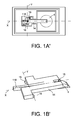
figure 1A' est une variante de réalisation de lafigure 1A , dans laquelle l'articulation en rotation est réalisée par une poutre déformable en flexion, - la
figure 1B' est une vue en perspective d'une variante de réalisation de lafigure 1A' , dans laquelle une articulation souple suivant l'axe X et rigide suivant l'axe Z entre la membrane et le bras de transmission est réalisée, - les
figures 2A et 2B sont des vues de dessus et en coupe longitudinale respectivement d'un exemple de réalisation d'un dispositif de mesure de pression à détection capacitive selon l'invention, - la
figure 3 est une vue de dessus d'un exemple de réalisation d'un dispositif de mesure de pression mettant en oeuvre des mesures capacitives différentielles, - la
figure 4 est une vue de dessus d'un autre exemple de réalisation d'un dispositif de mesure de pression à détection par jauge de contrainte comportant plusieurs membranes, - les
figures 5A et 5B sont des vues de dessus et en coupe le long de la ligne B-B respectivement d'un autre exemple de réalisation d'un dispositif de mesure de pression à détection par jauge de contrainte selon l'invention, présentant une butée mécanique à même de limiter les risques de surpression pouvant endommager le capteur, - les
figures 6A et 6B sont des vues de dessus et en coupe le long de la ligne C-C respectivement d'un autre exemple de réalisation d'un dispositif de mesure de pression à détection par jauge de contrainte selon l'invention présentant une rigidification localisée de la membrane déformable, - la
figure 7 est une vue de dessus d'un autre exemple de réalisation d'un dispositif de mesure de pression à détection par jauge de contrainte offrant une sensibilité réduite aux accélérations, - la
figure 8 est une vue de dessus d'un autre exemple de réalisation d'un dispositif de mesure de pression résonant, - la
figure 9 est une vue en coupe longitudinale d'un autre exemple d'un capteur selon l'invention à détection par jauge de contrainte, comportant une couche getter, - les
figures 10 et 11 sont des vues en coupe longitudinale de variantes de réalisation d'un dispositif de mesure de pression relatif ou microphone selon l'invention à détection par jauge de contrainte, munies d'évent, - les
figures 12A et 12B sont des vues de dessus et en coupe le long de la ligne D-D respectivement d'une variante de réalisation du dispositif de mesure de pression desfigures 1A et 1B , - la
figure 13 est une vue en coupe longitudinale d'un ensemble intégrant un dispositif de mesure de pression selon l'invention à détection par jauge de contrainte et un capteur inertiel, - la
figure 14 est une vue en coupe longitudinale d'une variante de réalisation de l'ensemble de lafigure 13 cette fois-ci avec des contacts électriques traversant du côté opposé de la membrane, - les
figures 15A à 15H sont des vues de dessus et en coupe longitudinale de différentes étapes de réalisation d'un dispositif de mesure de pression selon l'invention, - la
figure 16 est une vue de dessus d'un autre exemple d'un capteur selon l'invention à détection par jauge de contrainte, permettant la compensation de la pression statique et/ou l'auto-calibration et/ou l'autotest du capteur de pression; - les
figures 17A et 17B sont des vues de dessus et en coupe longitudinale le long du plan de coupe E-E d'un autre exemple d'un capteur selon l'invention à détection par jauge de contrainte, permettant la compensation de la pression statique et/ou l'auto-calibration et/ou l'autotest du capteur de pression; - la
figure 17A' est une vue en coupe longitudinale d'un autre exemple d'un capteur selon l'invention à détection par jauge de contrainte, permettant la compensation de la pression statique et/ou l'auto-calibration et/ou l'autotest du capteur de pression; - les
figures 18A et 18B sont des vues de dessus et en coupe longitudinale le long du plan de coupe E-E d'un autre exemple d'un capteur selon l'invention à détection par jauge de contrainte, comportant des moyens passifs de compensation de la pression statique; - la
figure 19 est une vue de dessus d'un exemple de réalisation d'un dispositif de mesure de pression mettant en oeuvre des mesures piézorésistives et comportant une articulation souple suivant l'axe X et rigide suivant l'axe Z entre la membrane et le bras de transmission.
- the
Figures 1A and 1B are views from above and in section along the line AA respectively of an exemplary embodiment of a pressure measuring device with suspended strain gage detection according to the invention, - the
Figure 1A ' is an alternative embodiment of theFigure 1A in which the rotational joint is formed by a flexibly deformable beam, - the
Figure 1B ' is a perspective view of an alternative embodiment of theFigure 1A ' , in which a flexible joint along the axis X and rigid along the Z axis between the membrane and the transmission arm is produced, - the
Figures 2A and 2B are views from above and in longitudinal section respectively of an exemplary embodiment of a capacitive detection pressure measuring device according to the invention, - the
figure 3 is a view from above of an exemplary embodiment of a pressure measuring device implementing differential capacitive measurements, - the
figure 4 is a view from above of another embodiment of a strain gauge detection pressure measuring device comprising a plurality of membranes, - the
Figures 5A and 5B are views from above and in section along the line BB respectively of another embodiment of a strain gauge detection pressure measuring device according to the invention, having a mechanical stop capable of limiting the risks of overpressure that could damage the sensor, - the
Figures 6A and 6B are views from above and in section along the line CC respectively of another exemplary embodiment of a strain gauge detection pressure measuring device according to the invention having a localized stiffening of the deformable membrane, - the
figure 7 is a top view of another embodiment of a strain gauge detection pressure measuring device offering reduced sensitivity to accelerations, - the
figure 8 is a view from above of another embodiment of a resonant pressure measuring device, - the
figure 9 is a longitudinal sectional view of another example of a sensor according to the invention with strain gauge detection, comprising a getter layer, - the
Figures 10 and 11 are views in longitudinal section of alternative embodiments of a relative pressure measuring device or microphone according to the invention with strain gauge detection, provided with vent, - the
Figures 12A and 12B are views from above and in section along the line DD respectively of an embodiment variant of the pressure measuring device of theFigures 1A and 1B , - the
figure 13 is a longitudinal sectional view of an assembly incorporating a pressure measuring device according to the invention with strain gauge detection and an inertial sensor, - the
figure 14 is a longitudinal sectional view of an alternative embodiment of the whole of thefigure 13 this time with electrical contacts crossing the opposite side of the membrane, - the
Figures 15A to 15H are views from above and in longitudinal section of different steps for producing a pressure measuring device according to the invention, - the
figure 16 is a view from above of another example of a sensor according to the invention with strain gauge detection, allowing the compensation of the static pressure and / or the self-calibration and / or the self-test of the pressure sensor ; - the
Figures 17A and 17B are views from above and in longitudinal section along the section plane EE of another example of a sensor according to the invention with strain gage detection, allowing the compensation of the static pressure and / or the calibration and / or self-test of the pressure sensor; - the
FIG. 17A ' is a longitudinal sectional view of another example of a sensor according to the invention with strain gauge detection, allowing the compensation of the static pressure and / or the self-calibration and / or the self-test of the sensor. pressure; - the
Figures 18A and 18B are views from above and in longitudinal section along the section plane EE of another example of a sensor according to the invention with strain gage detection, comprising passive means for compensating the static pressure; - the
figure 19 is a top view of an exemplary embodiment of a pressure measuring device implementing piezoresistive measurements and having a flexible joint along the axis X and rigid along the Z axis between the membrane and the transmission arm .
Dans la description qui va suivre, les capteurs sont de type MEMS et/ou NEMS, cependant ils seront désignés uniquement par le terme " capteur " à des fins de simplicité.In the following description, the sensors are of MEMS and / or NEMS type, however they will be designated solely by the term "sensor" for the sake of simplicity.
Les éléments et parties ayant la même fonction et la même forme seront désignés par les mêmes références.Elements and parts having the same function and the same shape will be designated by the same references.
Sur les
Dans la présente demande, on entend par « substrat » par soucis de simplification, le substrat support 2 et les couches disposées sur ce substrat support telles que par exemple la ou les couches dans laquelle ou lesquelles sont réalisées la membrane et le bras de transmission.In the present application, the term "substrate" for the sake of simplification, the
La membrane 4 est soumise sur une de ses faces 4.1 à la pression P que l'on souhaite mesurer, dans la représentation de la
Dans l'exemple représenté, la membrane 4 a la forme d'un disque (en pointillés sur la
Les moyens pour transmettre la déformation de la membrane 4 aux moyens de détection 6 sont formés par un bras 14 d'axe longitudinal X, monté mobile en rotation par rapport au substrat au niveau d'une première extrémité longitudinale 14.1, l'axe de rotation Y est sensiblement parallèle à la membrane et au plan du substrat. En outre, le bras 14 est rendu solidaire en mouvement de la membrane au niveau de sa deuxième extrémité longitudinale 14.2. Le bras est indéformable, i.e. il présente une rigidité supérieure à au moins 10 à 100 fois la rigidité de la membrane et des moyens de transmission. Le bras est suspendu au-dessus de la membrane, i.e. il est disposé au dessus de la membrane et un espace existe entre le bras 14 et la membrane, le seul contact entre le bras et la membrane se fait au niveau de la deuxième extrémité longitudinale 14.2 du bras 14.The means for transmitting the deformation of the
Le bras a, dans l'exemple représenté, la forme d'une poutre rigide à section rectangulaire. La poutre pourrait en variante avoir une forme trapézoïdale.The arm has, in the example shown, the shape of a rigid beam with rectangular section. The beam could alternatively have a trapezoidal shape.
De préférence, la deuxième extrémité longitudinale 14.2 du bras 14 est solidaire de la membrane au niveau ou proche de la zone présentant la déformation maximale. Le déplacement du bras autour de son axe de rotation Y vu par les moyens de détection est alors maximal et la sensibilité du capteur est alors optimisée.Preferably, the second longitudinal end 14.2 of the
II est bien entendu que la partie du bras 14 solidaire de la membrane pourrait être une autre partie que la deuxième extrémité longitudinale 14.2, entre la première 14.1 et la deuxième 14.2 extrémité longitudinale.It is understood that the portion of the
Les moyens de détection 6 sont disposés sur le substrat de sorte qu'ils détectent le déplacement de la première extrémité longitudinale 14.1 du bras, ce déplacement étant proportionnel à l'amplitude de déformation de la membrane 4. Le bras 14 formant un bras de levier, la contrainte vue par les moyens de détection 6 est amplifiée par rapport à la déformation de la membrane. Dans le cas d'une mesure par jauge, le bras de levier augmente la contrainte exercée sur les jauges mais diminue l'amplitude de déformation par rapport à l'amplitude de déformation de la membrane du fait de la loi de conservation des moments.The detection means 6 are arranged on the substrate so that they detect the displacement of the first longitudinal end 14.1 of the arm, this displacement being proportional to the amplitude of deformation of the
Dans une mode de réalisation représenté sur la
Dans un autre mode de réalisation et comme cela est représenté sur les
Sur les dispositifs représentés sur les
La raideur de la poutre 18 dans la direction transversale par rapport à l'axe Y est de préférence au moins 10 fois supérieure à la raideur en compression de la ou des jauges, ce qui permet d'éviter une déformation de la poutre et une réduction de la déformation transmise à la poutre.The stiffness of the
Les jauges 16 sont disposées de part d'autre de l'axe de rotation et du bras 14.The
Les moyens de détection pourraient ne comporter qu'une seule jauge de contrainte. La mise en oeuvre de deux jauges de contrainte permet d'effectuer des mesures différentielles, rendant le dispositif moins sensible thermiquement.The detection means could comprise only one strain gauge. The implementation of two strain gauges makes it possible to perform differential measurements, making the device less sensitive thermally.
Sur les plots d'ancrage des jauges sont formés des contacts électrique 22, 24. Sur l'un des plots 20, le contact électrique 24 est réalisé en face arrière du substrat 2, du côté membrane déformable, et peut servir pour polariser la jauge de contrainte 16. Le contact est connecté à la jauge au moyen d'un contact traversant ou via ou TSV (Through Silicon Vias en terminologie anglo-saxonne) et par l'intermédiaire du plot d'ancrage 20.On the anchoring studs of the gauges are formed
Les jauges de contrainte peuvent être en matériau piézoélectrique ou en matériau piézorésistif.The strain gauges may be of piezoelectric material or of piezoresistive material.
Les jauges sont orientées de sorte que leur axe sensible soit sensiblement parallèle au bras de liaison et donc qu'il soit sensiblement orthogonal à l'axe de rotation du bras de liaison. Par ailleurs, la ligne neutre de chaque jauge est disposée au-dessus ou au dessous de l'axe de rotation du bras de transmission. Pour cela les jauges peuvent présenter une épaisseur inférieure à celle de la poutre de torsion et/ou de flexion. Par exemple pour obtenir cette épaisseur plus faible à partir des mêmes couches, on peut déposer une surépaisseur sur lesdites poutres.The gauges are oriented so that their sensitive axis is substantially parallel to the link arm and therefore it is substantially orthogonal to the axis of rotation of the link arm. Furthermore, the neutral line of each gauge is disposed above or below the axis of rotation of the transmission arm. For this, the gauges may have a lower thickness to that of the torsion beam and / or flexion. For example, to obtain this lower thickness from the same layers, it is possible to deposit an excess thickness on said beams.
Nous allons maintenant expliquer le fonctionnement du capteur de pression des
Lorsqu'une différence de pression apparait entre la face 4.2 de la membrane 4 qui est en contact avec l'intérieur de la cavité 10, qui est à la pression de référence, et la face 4.1 de la membrane, qui est en contact avec l'environnement dont on souhaite mesurer la pression, la membrane se déforme. La déformation se fait soit vers l'intérieur de la cavité, soit vers l'extérieur de la cavité en fonction de la valeur de la pression à mesurer par rapport à la pression de référence.When a pressure difference appears between the face 4.2 of the
Cette déformation induit une force sur le bras 14 solidaire de la membrane, ce qui a pour effet de générer une contrainte dans les jauges de contrainte 16. Cette contrainte est amplifiée du fait du bras et de son pivotement autour de l'axe Y. La contrainte subie par les jauges 16 est alors mesurée par exemple, en mesurant la variation de résistance électrique des jauges dans le cas de jauges piézorésistives. Ces mesures permettent alors de déterminer la différence de pression vue par la membrane et la pression de l'environnement.This deformation induces a force on the
L'amplification de la contrainte par le bras de levier sera d'autant plus importante que la longueur du bras entre le point d'application de la force par la membrane et l'axe de rotation Y sera grande, que l'axe de rotation sera proche du point d'application de la contrainte sur la jauge. La contrainte sera également d'autant plus élevée que la section de la jauge (épaisseur, largeur) sera petite.The amplification of the constraint by the lever arm will be all the more important that the length of the arm between the point of application of the force by the membrane and the axis of rotation Y will be large, that the axis of rotation will be close to the point of application of the constraint on the gauge. The stress will be even higher as the section of the gauge (thickness, width) will be small.
Ainsi, la sensibilité du capteur est augmentée. II est donc possible d'offrir des capteurs plus performants ou alors de réduire la taille des capteurs, par exemple en réduisant la surface de la membrane, tout en conservant la même performance.Thus, the sensitivity of the sensor is increased. It is therefore possible to offer more efficient sensors or to reduce the size of the sensors, for example by reducing the surface of the membrane, while maintaining the same performance.
Sur les
Les moyens de détection 6' sont de type capacitif, i.e. la détection est obtenue par mesure d'une variation de capacité d'un condensateur 25. Les moyens de détection 6' comportent une électrode fixe 26 située sur le substrat 2 et une électrode mobile 28 solidaire du bras 14, et faisant face à l'électrode fixe 26. L'électrode mobile 28 est fixée à la première extrémité 14.1 du bras 14. L'électrode fixe 26 est connectée à un contact 30 et l'électrode mobile est reliée au contact électrique formé sur un des plots d'ancrage de l'axe de torsion 18.The detection means 6 'are of the capacitive type, ie the detection is obtained by measuring a capacitance variation of a
Lorsque la membrane 4 se déforme, le bras 14 entraîne avec lui l'électrode mobile 28, qui se déplace par rapport à l'électrode fixe 26. La distance d'entrefer entre les deux électrodes 26, 28 varie, cette variation est représentative de la déformation de la membrane 4 et donc de la pression de l'environnement.When the
Grâce à la mise en oeuvre du bras 14, le déplacement de l'électrode mobile 28 peut être amplifié par rapport à celui de la membrane 4. Ainsi pour une pression donnée, la variation de capacité est augmentée. La sensibilité du capteur de pression est donc augmentée.Thanks to the implementation of the
Sur la
Ce capteur diffère de celui des
II est à noter que, lorsque la capacité du condensateur 25 augmente, celle des condensateurs supplémentaires 32 diminue. De préférence, la distance entre l'axe de torsion 18 et l'électrode 28 est la même que celle entre l'axe de torsion est les électrodes 34 afin qu'elles voient la même amplification. Pour obtenir une mesure différentielle, la surface de l'électrode 28 est choisie égale à la somme des surfaces des deux électrodes 34.It should be noted that as the capacity of the
Sur la
Les déformations des quatre membranes 4 appliquent un effort sur le bras 14, or la surface totale des quatre membranes étant supérieure à celle d'une seule membrane, la force appliquée sur le bras et donc sur les jauges est augmentée. Cette réalisation est particulièrement intéressante pour les capteurs à jauge de contrainte, telles que les jauges piézorésistives ou résonantes.The deformations of the four
Sur les
La butée 38 sert à limiter le déplacement de la membrane 4, et donc celui du bras 14, pour protéger les jauges 16. En effet, en cas de choc de pression, la pression vue par la membrane peut sortir de la gamme de mesure prévue à la construction, et la membrane 4 via le bras 14 peut appliquer une contrainte supérieure à la contrainte que peut supporter la jauge ou les jauges 16.The
Il est possible de fixer simplement le niveau de pression à partir de laquelle le déplacement de la membrane et donc du bras, est limitée, en positionnant la butée 38 plus ou moins proche de la zone de la membrane présentant la déformation maximale.It is possible to simply set the pressure level from which the movement of the membrane and therefore the arm, is limited, by positioning the
On peut envisager que la butée soit au dessus du bras et forme directement une butée pour le bras, par exemple dans le cas où la butée est réalisée directement par la capot 12 ou sur le capot au-dessus du bras.It is conceivable that the stop is above the arm and directly forms a stop for the arm, for example in the case where the stop is made directly by the
Un contact électrique 40 peut être ajouté sur le plot d'ancrage de la butée afin de contrôler le potentiel de la butée, par exemple la butée pourrait être au potentiel de la membrane, ce qui permet d'éviter le risque de court-circuit en cas de contact de la membrane sur la butée et le risque d'une attraction électrostatique parasite de la membrane vers la butée.An
Sur la
Dans l'exemple représenté, la membrane 4 est rigidifiée localement en ajoutant des surépaisseurs radiales 41 sur la membrane 4, présentant une structure similaire à des baleines de parapluie. Une structure en nid d'abeille peut également convenir ou tout autres moyen augmentant la rigidité de la membrane. Le niveau de rigidification est choisi afin d'éviter de rendre le capteur trop sensible aux accélérations.In the example shown, the
Sur la
De préférence et comme cela est représenté sur la
Le capteur de pression est alors moins sensible, voire insensible à l'accélération hors-plan, i.e. à l'accélération tendant à faire défléchir la membrane.The pressure sensor is then less sensitive or insensitive to off-plane acceleration, i.e. acceleration tending to deflect the membrane.
Sur la
Le résonateur présente une épaisseur réduite par rapport à l'axe de torsion 18 afin d'être sensible au déplacement hors plan du bras 14.The resonator has a reduced thickness with respect to the
Le fonctionnement de ce capteur est le suivant : lorsque la membrane 4 se déforme, elle applique une contrainte au bras 14 qui la transmet au résonateur 44. Celui-ci est excité par les moyens d'excitation 48 et est mis en vibration à la résonance. Du fait de la contrainte qui lui est appliquée, sa fréquence de résonance varie, cette variation est alors mesurée par les moyens de détection 50. II est alors possible de remonter à la déformation de la membrane et donc à la pression de l'environnement.The operation of this sensor is as follows: when the
Sur la
Sur les
Sur la
Sur la
Ces dispositifs peuvent former un capteur de pression relative ou un microphone.These devices can form a relative pressure sensor or microphone.
Sur les
Sur la
Sur la
Dans l'exemple représenté, l'encapsulation du capteur inertiel CI est obtenue par la réalisation d'une cavité 58 distincte de la cavité 10 du capteur de pression, un cordon de scellement 60 les séparant. Cependant, dans le cas d'une cavité 10 fermée, il est envisageable de ne réaliser qu'une seule cavité pour les deux capteurs CP et CI.In the example shown, the encapsulation of the inertial sensor IC is obtained by producing a
Sur la
Sur la
Dans l'exemple représenté, le capteur de pression comporte des moyens de la compensation de la pression statique et/ou l'auto-calibration et/ou l'autotest du capteur de pression.In the example shown, the pressure sensor comprises means for the compensation of the static pressure and / or the self-calibration and / or the self-test of the pressure sensor.
Le capteur comporte deux paires d'électrodes 66.1, 66.2 d'actionnement capacitifs, l'une 66.1 étant située entre l'axe de rotation Y et la liaison avec la membrane 4 et l'autre 66.2 étant situé de l'autre côté de l'axe de rotation Y. Une électrode, dite électrode supérieure, de chaque paire est située sur le bras et l'autre électrode, dite électrode inférieure, de chaque paire est située sur le substrat mais isolée électriquement du substrat Les électrodes inférieures sont représentées en pointillés.The sensor comprises two pairs of capacitive actuating electrodes 66.1, 66.2, one 66.1 being located between the axis of rotation Y and the connection with the
Les électrodes supérieures de chaque paire sont connectées électriquement via le bras d'amplification et le plot 19. Le plot de contact 68 assure l'activation de l'électrode inférieure de la paire 66.1 et le plot de contact 70 assure l'activation de l'électrode inférieure de la paire 66.2.The upper electrodes of each pair are electrically connected via the amplification arm and the
Lors de l'activation des électrodes de la paire 66.1, 66.2, des forces électrostatiques apparaissent entre les l'électrode inférieure et les électrodes supérieures.Upon activation of the electrodes of the pair 66.1, 66.2, electrostatic forces occur between the lower electrode and the upper electrodes.
Dans la représentation de la
L'activation des électrodes 66.1 provoque un pivotement du bras 14 dans le sens horaire et un déplacement de la membrane en rapprochement du substrat 2, ce qui permet d'annuler tout ou partie de la déformation de la membrane issue de cette pression statique, pour ne mesurer que les variations de pression autour de cette pression statique.The activation of the electrodes 66.1 causes a pivoting of the
Par exemple, on peut souhaiter annuler une pression de l'ordre de 0,5 fois la pression atmosphérique.For example, it may be desirable to cancel a pressure of the order of 0.5 times the atmospheric pressure.
Ceci est particulièrement intéressant dans le cas d'un capteur de pression devant mesurer de très faibles variations de pression autour d'une valeur de pression statique.This is particularly interesting in the case of a pressure sensor to measure very small pressure variations around a static pressure value.
Une activation des électrodes 66.2 provoque un pivotement du bras dans le sens antihoraire et un déplacement de la membrane en éloignement du substrat 2.Activation of the electrodes 66.2 causes pivoting of the arm counterclockwise and displacement of the membrane away from the
L'activation des électrodes d'actionnement 66.2 permet d'effectuer des autotests. Le bon fonctionnement du capteur peut alors être vérifié en déformant la membrane 4 vers le haut par les moyens d'actionnement électrostatiques au moyen de la paire d'électrodes 66.2 et en vérifiant que les moyens de détection sont sensibles à cette déformation induite.Activation of the actuation electrodes 66.2 makes it possible to carry out self-tests. The correct operation of the sensor can then be verified by deforming the
L'activation des électrodes d'actionnement 66.2 permet également d'effectuer une auto-calibration. Dans ce cas on calibre le capteur de pression en appliquant entre les électrodes d'actionnement 66.2 une tension connue, induisant une déformation de la membrane qui « simule » une pression de référence, permettant ainsi de recaler le signal de sortie du capteur.The activation of the actuation electrodes 66.2 also makes it possible to carry out a self-calibration. In this case, the pressure sensor is calibrated by applying a voltage between the actuating electrodes 66.2. known, inducing a deformation of the membrane that "simulates" a reference pressure, thus allowing to reset the output signal of the sensor.
On utilise les moyens de détection, des jauges piézorésistives par exemple, pour mesurer les variations de pression autour de cette pression statique compensée.The detection means, piezoresistive gauges for example, are used to measure the pressure variations around this compensated static pressure.
Un capteur de pression ne comportant que les moyens d'autotest et/ou de calibration ou les moyens d'annulation de la pression statique ne sort pas du cadre de la présente invention.A pressure sensor comprising only the means of self-test and / or calibration or the means for canceling the static pressure is not outside the scope of the present invention.
La mise en oeuvre de ces électrodes peut permettre d'asservir en position le bras et la membrane, en particulier dans le cas d'une détection capacitive.The implementation of these electrodes can be used to enslave the arm and the membrane in position, in particular in the case of a capacitive detection.
De manière avantageuse, la paire d'électrodes 66.1 est située à l'opposé de l'axe de rotation par rapport à la membrane 4.Advantageously, the pair of electrodes 66.1 is located opposite the axis of rotation relative to the
Sur la
Dans cet exemple, l'électrode d'actionnement est telle qu'elle peut agir directement sur la membrane.In this example, the actuation electrode is such that it can act directly on the membrane.
Sur les
Dans un autre exemple, l'électrode d'actionnement 70' peut être située sous la membrane 14 en utilisant une partie du substrat. Pour cela, la section de l'ouverture d'arrivée de pression est réduite, ce qui permet d'avoir une partie du substrat en regard de la membrane. Cette exemple est représentée sur la
Sur les
Dans cet exemple de réalisation, un espace 72 est prévu entre la membrane et l'extrémité du bras de levier 14 afin de permettre une déformation de la membrane sans action sur le bras 14 dans une phase initiale de déformation de la membrane. L'espace 72 est déterminé en fonction de la proportion de pression statique à compenser. Par exemple, on peut souhaiter compenser 90% de cette pression statique, les jauges ne voient alors une contrainte qu'au-delà d'une pression appliquée au-dessus de 90% de la pression statique à compenser.In this embodiment, a
Grâce à cette réalisation, la résolution du capteur de pression peut être augmentée d'un facteur 5 à 10.With this embodiment, the resolution of the pressure sensor can be increased by a factor of 5 to 10.
En variante, le capteur de pression peut comporter en plus de l'espace 72 une liaison mécanique souple entre la membrane et le bras d'amplification Cette liaison souple est dimensionnée pour ne transmettre quasiment aucune contrainte aux jauges tant que la membrane n'est pas en contact mécanique direct avec le bras d'amplification 14. Cette liaison mécanique souple permet que la membrane et le bras 14 soient au même potentiel électrique quelque soit la pression. La liaison souple est par exemple formée par une poutre souple ou un ressort.As a variant, the pressure sensor may comprise, in addition to the
Sur la
Les variantes de réalisation ont été décrites en considérant un capteur de pression à détection par jauge de contrainte, mais les variantes des
On peut envisager de mettre en oeuvre plusieurs bras de levier transmettant chacun la déformation à des moyens de détection distincts disposés autour de la membrane, les bras de levier s'étendant radialement.It is conceivable to implement several lever arms each transmitting the deformation to separate detection means arranged around the membrane, the lever arms extending radially.
En outre, les différentes variantes peuvent être combinées sans sortir du cadre de la présente invention.In addition, the different variants can be combined without departing from the scope of the present invention.
Grâce à l'invention, on découple la membrane et les moyens de détection, ce qui permet de les optimiser séparément.Thanks to the invention, the membrane and the detection means are cut off, which makes it possible to optimize them separately.
De plus, l'amplification de la contrainte dans le cas d'un capteur résonant ou à détection par jauge de contrainte et l'amplification du déplacement dans le cas d'un capteur à détection capacitif, apporte un gain en sensibilité important, le capteur de pression peut être rendu plus performant ou sa taille peut être réduite.In addition, the amplification of the stress in the case of a resonant sensor or strain gage detection and the amplification of the displacement in the case of a sensor with capacitive detection, brings a gain in significant sensitivity, the sensor pressure can be made more efficient or its size can be reduced.
En outre, grâce à l'invention, la réalisation de capteurs de pression à mesure différentielle est technologiquement simplifiée, à la fois dans le cas de l'utilisation de moyens de détection piézorésistifs, que capacitifs ou résonants. Cette mesure différentielle permet d'augmenter le rapport signal/bruit et de limiter la sensibilité thermique du capteur.In addition, thanks to the invention, the realization of differential pressure sensors is technologically simplified, both in the case of the use of piezoresistive detection means, capacitive or resonant. This differential measurement makes it possible to increase the signal-to-noise ratio and to limit the thermal sensitivity of the sensor.
De plus, la technologie de réalisation des capteurs de pression selon l'invention étant très proche des technologies de fabrication des capteurs inertiels MEMS et/ou NEMS en technologie de surface, il est possible de mutualiser une grande partie des procédés existants. II est alors également possible de co-intégrer ces différents capteurs comme cela est représenté sur les
Dans le cas particulier d'une détection par jauge de contrainte, la jauge peut être de section nanométrique, ce qui assure une concentration de contrainte plus importante et offre une sensibilité accrue. En outre, les jauges sont protégées du milieu extérieur par le capot. Dans le cas d'une détection capacitive, le volume de la cavité 10 n'intervient pas dans l'entrefer électrostatique entre la membrane et l'électrode fixe. On peut alors réaliser une cavité 10 présentant un large volume sous vide, ce qui permet d'obtenir un vide de référence susceptible d'être plus stable et plus poussé que dans les capteurs conventionnels.In the particular case of a strain gauge detection, the gauge may be of nanometric section, which provides a higher concentration of stress and offers increased sensitivity. In addition, the gauges are protected from the outside by the hood. In the case of a capacitive detection, the volume of the
En outre, l'entrefer électrostatique qui se situe entre la membrane et l'électrode fixe est bien contrôlé car il est défini par une couche sacrificielle.In addition, the electrostatic gap between the membrane and the fixed electrode is well controlled because it is defined by a sacrificial layer.
La fermeture sous vide de la cavité est réalisée lors du scellement, par exemple eutectique, anodique, SDB (Silicon Direct Bonding), ou scellement direct. Dans ce cas le scellement utilise les forces de surface pour assurer l'adhésion des deux substrats..., ce type de fermeture permet d'obtenir une bonne qualité de vide, qui est plus fiable que celui obtenu au moyen d'un bouchage par dépôt.The vacuum closure of the cavity is performed during sealing, for example eutectic, anodic, SDB (Silicon Direct Bonding), or direct sealing. In this case the seal uses the surface forces to ensure the adhesion of the two substrates ..., this type of closure makes it possible to obtain a good quality of vacuum, which is more reliable than that obtained by means of a plugging by deposit.
Par ailleurs, le procédé de réalisation permet d'insérer un matériau getter dans la cavité sous vide 10, ce qui est particulièrement intéressant dans le cas où l'on souhaite avoir un vide de référence poussé et stable dans le temps, notamment pour réaliser un capteur sensible aux basses pressions.Moreover, the production method makes it possible to insert a getter material in the
Enfin, la reprise des contacts électriques de la membrane et du substrat peut être simplifiée, en utilisant une technologie de type TSV (Through Silicon Via) qui s'intègre au procédé de réalisation par technologie de surface de la partie sensible du capteur, et permettant une reprise des contacts soit par la face avant, soit par la face arrière du capteur.Finally, the recovery of the electrical contacts of the membrane and the substrate can be simplified, by using a technology of the type TSV (Through Silicon Via) which integrates with the process of realization by surface technology of the sensitive part of the sensor, and allowing a recovery of the contacts either by the front face or by the rear face of the sensor.
Nous allons maintenant décrire un exemple de procédé de réalisation du capteur de pression à détection par jauges de contraintes des
Les emplacements de différentes parties du capteur de pression, en cours de réalisation dans les différentes étapes représentées, sont désignés par les références de ces parties.The locations of different parts of the pressure sensor, in progress in the various steps shown, are designated by the references of these parts.
Il s'agit d'un procédé de réalisation en technologie de surface i.e. par dépôt et usinage successifs de couches minces sur un substrat de base.This is a method of realization in surface technology i.e. by successive deposition and machining of thin layers on a base substrate.
On part d'un substrat SOI 100 (Silicon on Insulator) qui peut être réalisé à partir d'un BOX ("Buried Oxyde") de 1 µm d'épaisseur et d'une couche de silicium actif 0,2 µm d'épaisseur. La deuxième couche peut être obtenue par épitaxie ou dépôt de silicium ou de SiGe.It starts from a
Le couche supérieure de silicium 102 a une épaisseur comprise entre quelques dizaines de nm et quelques µm. La couche d'oxyde du substrat SOI est désignée 101.The
On effectue une étape de lithographie afin de définir les jauges de contrainte, l'axe de torsion, le contour de la membrane 4 le contour des zones de contact et d'encastrement des jauges et de l'axe de torsion et l'ouverture de la reprise de contact en face arrière. Sur la
On effectue ensuite une gravure de la couche de silicium avec arrêt sur la couche d'oxyde 101. La résine restante est éliminée.The etch layer is then etched with the
On obtient l'élément représenté sur la
Lors d'une étape suivante, on effectue un dépôt d'une couche de SiO2 106. On effectue ensuite une lithographie pour protéger les jauges de contrainte, la membrane 4, et définir l'ouverture des zones de contact et des plots d'encastrement des jauges et de l'axe de torsion, et l'ouverture de la zone d'ancrage 64 du bras 14 sur la membrane 4. Une gravure d'oxyde des couches 101 et 106 a ensuite lieu avec arrêt sur le silicium de la couche 102 et sur le silicium du substrat SOI. La résine restante est éliminée. L'élément ainsi obtenu est visible sur la
Lors d'une étape suivante, a lieu un dépôt d'une couche 108 de silicium, monocristallin ou polycristallin, par exemple par épitaxie ayant typiquement une épaisseur comprise entre 1 µm et quelques dizaines de µm. Un polissage mécano-chimique de la couche 108 peut être réalisé. L'élément obtenu est visible sur la
Lors d'une étape suivante, on effectue une lithographie sur la couche 108 afin de définir la zone d'ouverture de la membrane 4, et la zone d'ouverture des jauges 16, et de définir le bras 14 et les zones d'isolation des contacts. On effectue ensuite une gravure de la couche 108 avec arrêt sur la couche de SiO2 106 et 101. La résine restante est éliminée. L'élément obtenu est visible sur la
Lors d'une étape suivante, on libère le bras 14, l'axe de torsion et les jauges par gravure par exemple au moyen d'acide fluorhydrique vapeur. Lors de cette étape, la couche 106 est entièrement gravée ainsi qu'une partie de la couche de SiO2 du substrat SOI. Lors de cette étape, la membrane 4 n'est pas encore libérée. L'élément obtenu est visible sur la
Lors d'une étape suivante, on effectue le scellement sous vide du capot au moyen d'un cordon 13. En variante, le scellement peut être par exemple de type eutectique, SDB ou anodique dans le cas d'un capot en verre, i.e. sans cordon, le scellement étant obtenu par adhésion directe des deux surfaces 12 et 108. On réalise préalablement une cavité dans le capot avant scellement, au moins au-dessus des parties mobiles.In a subsequent step, vacuum sealing of the cover is carried out by means of a bead 13. In a variant, the seal may for example be of the eutectic, SDB or anodic type in the case of a glass cover, ie cordless, the seal being obtained by direct adhesion of both
Le capot peut avoir été préalablement préparé. La préparation du capot peut comporter les étapes de réalisation d'une cavité, du dépôt de getter, de réalisation de routages électriques voire d'une électronique (co-integration CMOS) dans le cas d'un scellement eutectique,...The hood may have been previously prepared. The preparation of the cover may include the steps of making a cavity, the deposit of getter, making electrical routes or even an electronic (CMOS co-integration) in the case of eutectic sealing, ...
La cavité étanche 10 autour de la membrane est alors formée.The sealed
On réalise ensuite un amincissement du substrat par exemple par abrasion en face arrière ou "back-grinding" et polissage mécano-chimique. L'élément obtenu est visible sur la
Lors d'une étape suivante, on effectue un dépôt d'une couche métallique sur la face arrière du substrat afin de réaliser le contact en face arrière. Ensuite, une lithographie est effectuée sur cette couche pour délimiter le contact en face arrière et enfin une gravure de la couche métallique est réalisée. La résine sur la couche métallique restante est éliminée. Une nouvelle lithographie est réalisée en face arrière pour délimiter la zone d'isolation des contacts et l'ouverture de la membrane 4, ainsi qu'une gravure du substrat en face arrière, par exemple par gravure profonde par ions réactifs ou DRIE ("deep reactive-ion etching" en anglais) avec un arrêt sur la couche d'oxyde 101 du substrat SOI. La résine restante est éliminée. L'élément obtenu est visible sur la
Enfin, on effectue une gravure en face arrière de la couche d'oxyde du substrat SOI. La membrane est libérée. L'usinage du capteur inertiel est fait en même temps que la gravure de la partie MEMS (
En variante, il est envisageable d'utiliser à la place d'un substrat SOI un substrat standard, sur lequel un dépôt d'une couche sacrificielle, par exemple d'oxyde, a été effectué, ainsi qu'un dépôt d'une première couche de polysilicium ou de SiGe-Poly. Les étapes suivantes sont similaires à celles décrites en partant d'un substrat SOI.As a variant, it is conceivable to use, in place of a SOI substrate, a standard substrate on which a deposit of a sacrificial layer, for example an oxide layer, has been made, as well as a deposit of a first layer of polysilicon or SiGe-Poly. The following steps are similar to those described starting from an SOI substrate.
Les valeurs des épaisseurs sont données uniquement à titre d'exemple. D'une manière générale, les couches sacrificielles (en oxyde) sont comprises entre quelques dizaines de nm et quelques microns, et les couches actives, comme le Si, SiGe, ... sont comprises entre quelques dizaines de nm et quelques dizaines de µm.Thickness values are given by way of example only. In general, the sacrificial layers (oxide) are between a few tens of nm and a few microns, and the active layers, such as Si, SiGe, ... are between a few tens of nm and a few tens of microns. .
Le dispositif de mesure de pression selon l'invention peut être utilisé dans tous les domaines où une mesures de pression est requise, par exemple dans le domaine automobile, médicale, dans l'avionique, et également pour des applications grand public. En outre, ce capteur peut être utilisé pour réaliser un microphone pour des applications grand public, comme par exemple dans des téléphones portables, ou le domaine médical pour réaliser des prothèses auditives,....The pressure measuring device according to the invention can be used in all fields where a pressure measurement is required, for example in the automotive, medical, avionics, and also for consumer applications. In addition, this sensor can be used to make a microphone for consumer applications, such as in mobile phones, or the medical field for making hearing aids, etc.
Claims (25)
Applications Claiming Priority (1)
| Application Number | Priority Date | Filing Date | Title |
|---|---|---|---|
| FR1155954A FR2977319B1 (en) | 2011-07-01 | 2011-07-01 | OPTIMIZED SENSIBLITY PRESSURE MEASURING DEVICE |
Publications (2)
| Publication Number | Publication Date |
|---|---|
| EP2541222A1 true EP2541222A1 (en) | 2013-01-02 |
| EP2541222B1 EP2541222B1 (en) | 2018-02-21 |
Family
ID=46319660
Family Applications (1)
| Application Number | Title | Priority Date | Filing Date |
|---|---|---|---|
| EP12174451.0A Active EP2541222B1 (en) | 2011-07-01 | 2012-06-29 | Pressure-measurement device with optimised sensitivity |
Country Status (4)
| Country | Link |
|---|---|
| US (1) | US9157821B2 (en) |
| EP (1) | EP2541222B1 (en) |
| JP (1) | JP6053357B2 (en) |
| FR (1) | FR2977319B1 (en) |
Cited By (11)
| Publication number | Priority date | Publication date | Assignee | Title |
|---|---|---|---|---|
| FR3030739A1 (en) * | 2014-12-18 | 2016-06-24 | Commissariat Energie Atomique | DYNAMIC PRESSURE SENSOR WITH IMPROVED OPERATION |
| EP3070963A1 (en) | 2015-03-20 | 2016-09-21 | Commissariat à l'Énergie Atomique et aux Énergies Alternatives | Mems and/or nems pressure sensor with improved performances and dynamic microphone with such a sensor |
| EP3118598A4 (en) * | 2014-03-13 | 2017-11-08 | Seiko Instruments Inc. | Pressure sensor |
| US9910073B2 (en) | 2014-04-15 | 2018-03-06 | Commissariat A L'energie Atomique Et Aux Energies Alternatives | Measurement circuit |
| US10126333B2 (en) | 2013-12-20 | 2018-11-13 | Commissariat A L'energie Atomique Et Aux Energies Alternatives | Multisensory detector |
| CN110049942A (en) * | 2016-12-07 | 2019-07-23 | 原子能和替代能源委员会 | For transmitting mobile and power equipment between two regions being isolated from each other |
| CN110383027A (en) * | 2017-03-02 | 2019-10-25 | 罗伯特·博世有限公司 | Micro mechanical pressure sensor |
| CN112229749A (en) * | 2020-09-02 | 2021-01-15 | 厦门大学 | Micro-nano structure mechanical characteristic parameter measuring device, measuring plate and measuring method |
| EP3975584A1 (en) * | 2020-09-29 | 2022-03-30 | Commissariat à l'Energie Atomique et aux Energies Alternatives | Method for manufacturing an electroacoustic transducer |
| EP3975588A1 (en) * | 2020-09-29 | 2022-03-30 | Commissariat à l'Energie Atomique et aux Energies Alternatives | Method for manufacturing an electroacoustic transducer |
| EP4221256A1 (en) * | 2022-01-28 | 2023-08-02 | Commissariat à l'énergie atomique et aux énergies alternatives | Method for manufacturing a low noise electroacoustic transducer |
Families Citing this family (24)
| Publication number | Priority date | Publication date | Assignee | Title |
|---|---|---|---|---|
| FR2983189B1 (en) | 2011-11-30 | 2014-02-07 | Commissariat Energie Atomique | METHOD FOR PRODUCING A STRUCTURE COMPRISING AT LEAST ONE ACTIVE PART HAVING DIFFERENT THICKNESS AREAS |
| US9290067B2 (en) * | 2012-08-30 | 2016-03-22 | Freescale Semiconductor, Inc. | Pressure sensor with differential capacitive output |
| FR2995995B1 (en) * | 2012-09-26 | 2014-09-19 | Sagem Defense Securite | PRESSURE SENSOR BASED ON NANOJAUGES COUPLEES WITH A RESONATOR |
| FR3000484B1 (en) * | 2012-12-27 | 2017-11-10 | Tronic's Microsystems | MICROELECTROMECHANICAL DEVICE COMPRISING A MOBILE MASS THAT IS ABLE TO MOVE OUT OF THE PLAN |
| FR3005045A1 (en) | 2013-04-25 | 2014-10-31 | Commissariat Energie Atomique | MICROELECTROMECHANICAL AND / OR NANOELECTROMECHANICAL STRUCTURE WITH ADJUSTABLE QUALITY FACTOR |
| US20140355387A1 (en) | 2013-06-03 | 2014-12-04 | Qualcomm Incorporated | Ultrasonic receiver with coated piezoelectric layer |
| DE102014210006A1 (en) * | 2014-02-18 | 2015-08-20 | Robert Bosch Gmbh | Sensor unit and method for producing a sensor unit |
| FR3018916B1 (en) * | 2014-03-19 | 2017-08-25 | Commissariat Energie Atomique | MICROELECTROMECHANICAL AND / OR NANOELECTROMECHANICAL DIFFERENTIAL PRESSURE MEASURING SENSOR |
| FR3021309A1 (en) | 2014-05-26 | 2015-11-27 | Commissariat Energie Atomique | CAPACITIVE CAPACITIVE MICROELECTRONIC AND / OR NANOELECTRONIC DEVICE WITH INCREASED COMPACITY |
| US9689770B2 (en) * | 2014-07-17 | 2017-06-27 | Infineon Technologies Ag | Selfcalibration of capacitive pressure sensors with electrostatic forces |
| CN205262665U (en) * | 2015-06-22 | 2016-05-25 | 意法半导体股份有限公司 | Pressure sensor |
| JP6430355B2 (en) * | 2015-10-16 | 2018-11-28 | 株式会社東芝 | Sensor device |
| EP3387402B1 (en) * | 2015-12-07 | 2021-04-07 | EILERSEN, Nils Aage Juul | Load cell |
| DE102015121859A1 (en) * | 2015-12-15 | 2017-06-22 | Endress+Hauser Gmbh+Co. Kg | Pressure sensor and method for operating a pressure sensor |
| DE102016210479A1 (en) | 2016-06-14 | 2017-12-14 | Robert Bosch Gmbh | Micromechanical component for a pressure sensor device |
| US11003884B2 (en) * | 2016-06-16 | 2021-05-11 | Qualcomm Incorporated | Fingerprint sensor device and methods thereof |
| US20180005851A1 (en) * | 2016-07-01 | 2018-01-04 | Lam Research Corporation | Chamber filler kit for dielectric etch chamber |
| US10063978B2 (en) * | 2016-09-13 | 2018-08-28 | Akustica, Inc. | Cantilevered shear resonance microphone |
| DE102017200057A1 (en) * | 2017-01-04 | 2018-07-05 | Robert Bosch Gmbh | Linearized micromechanical sensor |
| CN209326840U (en) | 2018-12-27 | 2019-08-30 | 热敏碟公司 | Pressure sensor and pressure transmitter |
| CN109738098A (en) * | 2018-12-29 | 2019-05-10 | 菲比蓝科技(深圳)有限公司 | Pressure sensor and forming method thereof |
| FR3098810B1 (en) * | 2019-07-18 | 2021-10-15 | Commissariat Energie Atomique | Mechanical connection for MEMS and NEMS device for measuring a pressure variation and device comprising such a mechanical connection |
| FR3098809B1 (en) | 2019-07-18 | 2021-06-18 | Commissariat Energie Atomique | Mechanical link for MEMS and NEMS mechanical structure, and MEMS and NEMS structure including such a mechanical link |
| JP7216921B2 (en) * | 2020-01-10 | 2023-02-02 | 横河電機株式会社 | vibrating pressure sensor |
Citations (2)
| Publication number | Priority date | Publication date | Assignee | Title |
|---|---|---|---|---|
| EP0143738A1 (en) | 1983-09-30 | 1985-06-05 | Siemens Aktiengesellschaft | Pressure sensor with a pressure-sensitive diaphragm |
| US20040168519A1 (en) * | 2001-06-08 | 2004-09-02 | Edvard Kalvensten | Miniaturized pressure sensor |
Family Cites Families (17)
| Publication number | Priority date | Publication date | Assignee | Title |
|---|---|---|---|---|
| JPS61129545A (en) * | 1984-11-28 | 1986-06-17 | Nagano Keiki Seisakusho:Kk | Fine differential pressure transducer |
| JPH01242933A (en) * | 1988-03-24 | 1989-09-27 | Yokogawa Electric Corp | Semiconductor pressure sensor |
| US5295395A (en) * | 1991-02-07 | 1994-03-22 | Hocker G Benjamin | Diaphragm-based-sensors |
| FR2674627B1 (en) * | 1991-03-27 | 1994-04-29 | Commissariat Energie Atomique | RESONANT PRESSURE SENSOR. |
| FR2687783B1 (en) | 1992-02-20 | 1994-05-20 | Sextant Avionique | PRESSURE MICRO SENSOR. |
| US5458000A (en) * | 1993-07-20 | 1995-10-17 | Honeywell Inc. | Static pressure compensation of resonant integrated microbeam sensors |
| JP3145274B2 (en) * | 1995-06-07 | 2001-03-12 | 株式会社山武 | Pressure sensor |
| US5573679A (en) | 1995-06-19 | 1996-11-12 | Alberta Microelectronic Centre | Fabrication of a surface micromachined capacitive microphone using a dry-etch process |
| JPH10282130A (en) * | 1997-04-01 | 1998-10-23 | Canon Inc | Probe and scanning probe microscope using it |
| US5824910A (en) * | 1997-04-16 | 1998-10-20 | The United States Of America As Represented By The Secretary Of The Navy | Miniature hydrostat fabricated using multiple microelectromechanical processes |
| JP2002055008A (en) * | 2000-08-11 | 2002-02-20 | Anelva Corp | Vacuum sensor with built-in thin-film getter |
| JP4724488B2 (en) * | 2005-02-25 | 2011-07-13 | 日立オートモティブシステムズ株式会社 | Integrated microelectromechanical system |
| DE102006011545B4 (en) | 2006-03-14 | 2016-03-17 | Robert Bosch Gmbh | Micromechanical combination component and corresponding manufacturing method |
| AU2007302788B2 (en) * | 2006-09-28 | 2010-12-16 | Medtronic, Inc. | Capacitive interface circuit for low power sensor system |
| US8387464B2 (en) * | 2009-11-30 | 2013-03-05 | Freescale Semiconductor, Inc. | Laterally integrated MEMS sensor device with multi-stimulus sensing |
| US8316718B2 (en) * | 2010-08-23 | 2012-11-27 | Freescale Semiconductor, Inc. | MEMS pressure sensor device and method of fabricating same |
| FR3005045A1 (en) | 2013-04-25 | 2014-10-31 | Commissariat Energie Atomique | MICROELECTROMECHANICAL AND / OR NANOELECTROMECHANICAL STRUCTURE WITH ADJUSTABLE QUALITY FACTOR |
-
2011
- 2011-07-01 FR FR1155954A patent/FR2977319B1/en not_active Expired - Fee Related
-
2012
- 2012-06-29 EP EP12174451.0A patent/EP2541222B1/en active Active
- 2012-06-29 US US13/538,143 patent/US9157821B2/en active Active
- 2012-07-02 JP JP2012148491A patent/JP6053357B2/en active Active
Patent Citations (2)
| Publication number | Priority date | Publication date | Assignee | Title |
|---|---|---|---|---|
| EP0143738A1 (en) | 1983-09-30 | 1985-06-05 | Siemens Aktiengesellschaft | Pressure sensor with a pressure-sensitive diaphragm |
| US20040168519A1 (en) * | 2001-06-08 | 2004-09-02 | Edvard Kalvensten | Miniaturized pressure sensor |
Cited By (20)
| Publication number | Priority date | Publication date | Assignee | Title |
|---|---|---|---|---|
| US10126333B2 (en) | 2013-12-20 | 2018-11-13 | Commissariat A L'energie Atomique Et Aux Energies Alternatives | Multisensory detector |
| EP3118598A4 (en) * | 2014-03-13 | 2017-11-08 | Seiko Instruments Inc. | Pressure sensor |
| US10094724B2 (en) | 2014-03-13 | 2018-10-09 | Seiko Instruments Inc. | Pressure sensor |
| US9910073B2 (en) | 2014-04-15 | 2018-03-06 | Commissariat A L'energie Atomique Et Aux Energies Alternatives | Measurement circuit |
| WO2016097302A3 (en) * | 2014-12-18 | 2016-08-11 | Commissariat à l'énergie atomique et aux énergies alternatives | Dynamic pressure sensor with improved operation |
| US10345176B2 (en) | 2014-12-18 | 2019-07-09 | Commissariat A L'energie Atomique Et Aux Energies Alternatives | Dynamic pressure sensor with improved operation |
| FR3030739A1 (en) * | 2014-12-18 | 2016-06-24 | Commissariat Energie Atomique | DYNAMIC PRESSURE SENSOR WITH IMPROVED OPERATION |
| EP3070963A1 (en) | 2015-03-20 | 2016-09-21 | Commissariat à l'Énergie Atomique et aux Énergies Alternatives | Mems and/or nems pressure sensor with improved performances and dynamic microphone with such a sensor |
| CN110049942B (en) * | 2016-12-07 | 2023-03-10 | 原子能和替代能源委员会 | Device for transmitting movements and forces between two areas isolated from each other |
| CN110049942A (en) * | 2016-12-07 | 2019-07-23 | 原子能和替代能源委员会 | For transmitting mobile and power equipment between two regions being isolated from each other |
| CN110383027A (en) * | 2017-03-02 | 2019-10-25 | 罗伯特·博世有限公司 | Micro mechanical pressure sensor |
| CN112229749A (en) * | 2020-09-02 | 2021-01-15 | 厦门大学 | Micro-nano structure mechanical characteristic parameter measuring device, measuring plate and measuring method |
| CN112229749B (en) * | 2020-09-02 | 2021-07-09 | 厦门大学 | Micro-nano structure mechanical characteristic parameter measuring device, measuring plate and measuring method |
| EP3975584A1 (en) * | 2020-09-29 | 2022-03-30 | Commissariat à l'Energie Atomique et aux Energies Alternatives | Method for manufacturing an electroacoustic transducer |
| EP3975588A1 (en) * | 2020-09-29 | 2022-03-30 | Commissariat à l'Energie Atomique et aux Energies Alternatives | Method for manufacturing an electroacoustic transducer |
| FR3114583A1 (en) * | 2020-09-29 | 2022-04-01 | Commissariat A L'energie Atomique Et Aux Energies Alternatives | METHOD FOR MANUFACTURING AN ELECTROACOUSTIC TRANSDUCER |
| FR3114584A1 (en) * | 2020-09-29 | 2022-04-01 | Commissariat A L'energie Atomique Et Aux Energies Alternatives | METHOD FOR MANUFACTURING AN ELECTROACOUSTIC TRANSDUCER |
| US11661336B2 (en) | 2020-09-29 | 2023-05-30 | Commissariat A L'energie Atomique Et Aux Energies Alternatives | Method for manufacturing an electroacoustic transducer |
| EP4221256A1 (en) * | 2022-01-28 | 2023-08-02 | Commissariat à l'énergie atomique et aux énergies alternatives | Method for manufacturing a low noise electroacoustic transducer |
| FR3132402A1 (en) * | 2022-01-28 | 2023-08-04 | Commissariat A L'energie Atomique Et Aux Energies Alternatives | METHOD FOR MAKING A LOW-NOISE ELECTROACOUSTIC TRANSDUCER |
Also Published As
| Publication number | Publication date |
|---|---|
| US9157821B2 (en) | 2015-10-13 |
| JP6053357B2 (en) | 2016-12-27 |
| EP2541222B1 (en) | 2018-02-21 |
| JP2013015524A (en) | 2013-01-24 |
| FR2977319B1 (en) | 2014-03-14 |
| US20130000411A1 (en) | 2013-01-03 |
| FR2977319A1 (en) | 2013-01-04 |
Similar Documents
| Publication | Publication Date | Title |
|---|---|---|
| EP2541222B1 (en) | Pressure-measurement device with optimised sensitivity | |
| EP2367015B1 (en) | Force sensor with reduced noise | |
| EP2211185B1 (en) | Inertial sensor unit or resonant sensor with surface technology, with out-of-plane detection by strain gauge | |
| EP2211143B1 (en) | Micromachined planar gyrometer with an out-of-plane detection by strain gauge | |
| EP2008965B1 (en) | Resonant device with piezoresistive detection made using surface technologies | |
| EP2491406B1 (en) | Sensor for in-plane piezoresistive detection | |
| EP2065713B1 (en) | Detection device with a hanging piezoresistive strain gauge comprising a strain amplification cell | |
| EP2921836A1 (en) | Sensor for measuring microelectromechanical and/or nanoelectromechanical differential pressure | |
| EP2607907B1 (en) | Micro/nano multiaxial inertial motion sensor device | |
| EP2405238B1 (en) | Vibrating disk inertial rotary motion sensor | |
| EP2815210B1 (en) | Compact dection device for at least one acceleration and one rotational speed | |
| EP3599469B1 (en) | Accelerometer with detection by strain gauge with improved precision | |
| EP3234536B1 (en) | Dynamic pressure sensor with improved operation | |
| EP3766830B1 (en) | Mechanical link for mechanical mems and nems structure, and mems and nems structure comprising such a mechanical link | |
| EP3766829B1 (en) | Mechanical link for mems and nems device for measuring a pressure variation and device comprising such a mechanical link | |
| EP2949621B1 (en) | Capacitive micro and/ or nanoelectronic device having increased compactness | |
| EP3722254A1 (en) | Hinge providing reduced sensitivity to internal constraints | |
| FR3094708A1 (en) | OFF-PLAN HINGE FOR MICROMECHANICAL AND / OR NANOMECHANICAL STRUCTURE WITH REDUCED SENSITIVITY TO INTERNAL CONSTRAINTS | |
| FR3031639A1 (en) | ELECTROMECHANICAL TRANSDUCER INTEGRATING A DEFORMABLE ELEMENT OF RESONATOR OR MEMBRANE TYPE, AND MEASUREMENT SENSOR INTEGRATING SUCH TRANSDUCER | |
| WO2016024064A1 (en) | Microelectromechanical device sensitive to mechanical forces applied off-plane |
Legal Events
| Date | Code | Title | Description |
|---|---|---|---|
| PUAI | Public reference made under article 153(3) epc to a published international application that has entered the european phase |
Free format text: ORIGINAL CODE: 0009012 |
|
| AK | Designated contracting states |
Kind code of ref document: A1 Designated state(s): AL AT BE BG CH CY CZ DE DK EE ES FI FR GB GR HR HU IE IS IT LI LT LU LV MC MK MT NL NO PL PT RO RS SE SI SK SM TR |
|
| AX | Request for extension of the european patent |
Extension state: BA ME |
|
| 17P | Request for examination filed |
Effective date: 20130702 |
|
| RBV | Designated contracting states (corrected) |
Designated state(s): AL AT BE BG CH CY CZ DE DK EE ES FI FR GB GR HR HU IE IS IT LI LT LU LV MC MK MT NL NO PL PT RO RS SE SI SK SM TR |
|
| GRAP | Despatch of communication of intention to grant a patent |
Free format text: ORIGINAL CODE: EPIDOSNIGR1 |
|
| STAA | Information on the status of an ep patent application or granted ep patent |
Free format text: STATUS: GRANT OF PATENT IS INTENDED |
|
| INTG | Intention to grant announced |
Effective date: 20170829 |
|
| GRAS | Grant fee paid |
Free format text: ORIGINAL CODE: EPIDOSNIGR3 |
|
| GRAA | (expected) grant |
Free format text: ORIGINAL CODE: 0009210 |
|
| STAA | Information on the status of an ep patent application or granted ep patent |
Free format text: STATUS: THE PATENT HAS BEEN GRANTED |
|
| AK | Designated contracting states |
Kind code of ref document: B1 Designated state(s): AL AT BE BG CH CY CZ DE DK EE ES FI FR GB GR HR HU IE IS IT LI LT LU LV MC MK MT NL NO PL PT RO RS SE SI SK SM TR |
|
| REG | Reference to a national code |
Ref country code: GB Ref legal event code: FG4D Free format text: NOT ENGLISH |
|
| REG | Reference to a national code |
Ref country code: CH Ref legal event code: EP |
|
| REG | Reference to a national code |
Ref country code: AT Ref legal event code: REF Ref document number: 972275 Country of ref document: AT Kind code of ref document: T Effective date: 20180315 |
|
| REG | Reference to a national code |
Ref country code: IE Ref legal event code: FG4D Free format text: LANGUAGE OF EP DOCUMENT: FRENCH |
|
| REG | Reference to a national code |
Ref country code: DE Ref legal event code: R096 Ref document number: 602012042955 Country of ref document: DE |
|
| REG | Reference to a national code |
Ref country code: NL Ref legal event code: MP Effective date: 20180221 Ref country code: FR Ref legal event code: PLFP Year of fee payment: 7 |
|
| REG | Reference to a national code |
Ref country code: LT Ref legal event code: MG4D |
|
| REG | Reference to a national code |
Ref country code: AT Ref legal event code: MK05 Ref document number: 972275 Country of ref document: AT Kind code of ref document: T Effective date: 20180221 |
|
| PG25 | Lapsed in a contracting state [announced via postgrant information from national office to epo] |
Ref country code: NL Free format text: LAPSE BECAUSE OF FAILURE TO SUBMIT A TRANSLATION OF THE DESCRIPTION OR TO PAY THE FEE WITHIN THE PRESCRIBED TIME-LIMIT Effective date: 20180221 Ref country code: HR Free format text: LAPSE BECAUSE OF FAILURE TO SUBMIT A TRANSLATION OF THE DESCRIPTION OR TO PAY THE FEE WITHIN THE PRESCRIBED TIME-LIMIT Effective date: 20180221 Ref country code: CY Free format text: LAPSE BECAUSE OF FAILURE TO SUBMIT A TRANSLATION OF THE DESCRIPTION OR TO PAY THE FEE WITHIN THE PRESCRIBED TIME-LIMIT Effective date: 20180221 Ref country code: ES Free format text: LAPSE BECAUSE OF FAILURE TO SUBMIT A TRANSLATION OF THE DESCRIPTION OR TO PAY THE FEE WITHIN THE PRESCRIBED TIME-LIMIT Effective date: 20180221 Ref country code: LT Free format text: LAPSE BECAUSE OF FAILURE TO SUBMIT A TRANSLATION OF THE DESCRIPTION OR TO PAY THE FEE WITHIN THE PRESCRIBED TIME-LIMIT Effective date: 20180221 Ref country code: NO Free format text: LAPSE BECAUSE OF FAILURE TO SUBMIT A TRANSLATION OF THE DESCRIPTION OR TO PAY THE FEE WITHIN THE PRESCRIBED TIME-LIMIT Effective date: 20180521 Ref country code: FI Free format text: LAPSE BECAUSE OF FAILURE TO SUBMIT A TRANSLATION OF THE DESCRIPTION OR TO PAY THE FEE WITHIN THE PRESCRIBED TIME-LIMIT Effective date: 20180221 |
|
| PG25 | Lapsed in a contracting state [announced via postgrant information from national office to epo] |
Ref country code: AT Free format text: LAPSE BECAUSE OF FAILURE TO SUBMIT A TRANSLATION OF THE DESCRIPTION OR TO PAY THE FEE WITHIN THE PRESCRIBED TIME-LIMIT Effective date: 20180221 Ref country code: SE Free format text: LAPSE BECAUSE OF FAILURE TO SUBMIT A TRANSLATION OF THE DESCRIPTION OR TO PAY THE FEE WITHIN THE PRESCRIBED TIME-LIMIT Effective date: 20180221 Ref country code: LV Free format text: LAPSE BECAUSE OF FAILURE TO SUBMIT A TRANSLATION OF THE DESCRIPTION OR TO PAY THE FEE WITHIN THE PRESCRIBED TIME-LIMIT Effective date: 20180221 Ref country code: GR Free format text: LAPSE BECAUSE OF FAILURE TO SUBMIT A TRANSLATION OF THE DESCRIPTION OR TO PAY THE FEE WITHIN THE PRESCRIBED TIME-LIMIT Effective date: 20180522 Ref country code: RS Free format text: LAPSE BECAUSE OF FAILURE TO SUBMIT A TRANSLATION OF THE DESCRIPTION OR TO PAY THE FEE WITHIN THE PRESCRIBED TIME-LIMIT Effective date: 20180221 Ref country code: BG Free format text: LAPSE BECAUSE OF FAILURE TO SUBMIT A TRANSLATION OF THE DESCRIPTION OR TO PAY THE FEE WITHIN THE PRESCRIBED TIME-LIMIT Effective date: 20180521 |
|
| PG25 | Lapsed in a contracting state [announced via postgrant information from national office to epo] |
Ref country code: MT Free format text: LAPSE BECAUSE OF FAILURE TO SUBMIT A TRANSLATION OF THE DESCRIPTION OR TO PAY THE FEE WITHIN THE PRESCRIBED TIME-LIMIT Effective date: 20180221 |
|
| PG25 | Lapsed in a contracting state [announced via postgrant information from national office to epo] |
Ref country code: AL Free format text: LAPSE BECAUSE OF FAILURE TO SUBMIT A TRANSLATION OF THE DESCRIPTION OR TO PAY THE FEE WITHIN THE PRESCRIBED TIME-LIMIT Effective date: 20180221 Ref country code: EE Free format text: LAPSE BECAUSE OF FAILURE TO SUBMIT A TRANSLATION OF THE DESCRIPTION OR TO PAY THE FEE WITHIN THE PRESCRIBED TIME-LIMIT Effective date: 20180221 Ref country code: PL Free format text: LAPSE BECAUSE OF FAILURE TO SUBMIT A TRANSLATION OF THE DESCRIPTION OR TO PAY THE FEE WITHIN THE PRESCRIBED TIME-LIMIT Effective date: 20180221 Ref country code: RO Free format text: LAPSE BECAUSE OF FAILURE TO SUBMIT A TRANSLATION OF THE DESCRIPTION OR TO PAY THE FEE WITHIN THE PRESCRIBED TIME-LIMIT Effective date: 20180221 Ref country code: IT Free format text: LAPSE BECAUSE OF FAILURE TO SUBMIT A TRANSLATION OF THE DESCRIPTION OR TO PAY THE FEE WITHIN THE PRESCRIBED TIME-LIMIT Effective date: 20180221 |
|
| REG | Reference to a national code |
Ref country code: DE Ref legal event code: R097 Ref document number: 602012042955 Country of ref document: DE |
|
| PG25 | Lapsed in a contracting state [announced via postgrant information from national office to epo] |
Ref country code: SM Free format text: LAPSE BECAUSE OF FAILURE TO SUBMIT A TRANSLATION OF THE DESCRIPTION OR TO PAY THE FEE WITHIN THE PRESCRIBED TIME-LIMIT Effective date: 20180221 Ref country code: CZ Free format text: LAPSE BECAUSE OF FAILURE TO SUBMIT A TRANSLATION OF THE DESCRIPTION OR TO PAY THE FEE WITHIN THE PRESCRIBED TIME-LIMIT Effective date: 20180221 Ref country code: DK Free format text: LAPSE BECAUSE OF FAILURE TO SUBMIT A TRANSLATION OF THE DESCRIPTION OR TO PAY THE FEE WITHIN THE PRESCRIBED TIME-LIMIT Effective date: 20180221 Ref country code: SK Free format text: LAPSE BECAUSE OF FAILURE TO SUBMIT A TRANSLATION OF THE DESCRIPTION OR TO PAY THE FEE WITHIN THE PRESCRIBED TIME-LIMIT Effective date: 20180221 |
|
| PLBE | No opposition filed within time limit |
Free format text: ORIGINAL CODE: 0009261 |
|
| STAA | Information on the status of an ep patent application or granted ep patent |
Free format text: STATUS: NO OPPOSITION FILED WITHIN TIME LIMIT |
|
| 26N | No opposition filed |
Effective date: 20181122 |
|
| REG | Reference to a national code |
Ref country code: CH Ref legal event code: PL |
|
| PG25 | Lapsed in a contracting state [announced via postgrant information from national office to epo] |
Ref country code: SI Free format text: LAPSE BECAUSE OF FAILURE TO SUBMIT A TRANSLATION OF THE DESCRIPTION OR TO PAY THE FEE WITHIN THE PRESCRIBED TIME-LIMIT Effective date: 20180221 |
|
| REG | Reference to a national code |
Ref country code: BE Ref legal event code: MM Effective date: 20180630 |
|
| PG25 | Lapsed in a contracting state [announced via postgrant information from national office to epo] |
Ref country code: LU Free format text: LAPSE BECAUSE OF NON-PAYMENT OF DUE FEES Effective date: 20180629 Ref country code: MC Free format text: LAPSE BECAUSE OF FAILURE TO SUBMIT A TRANSLATION OF THE DESCRIPTION OR TO PAY THE FEE WITHIN THE PRESCRIBED TIME-LIMIT Effective date: 20180221 |
|
| REG | Reference to a national code |
Ref country code: IE Ref legal event code: MM4A |
|
| PG25 | Lapsed in a contracting state [announced via postgrant information from national office to epo] |
Ref country code: CH Free format text: LAPSE BECAUSE OF NON-PAYMENT OF DUE FEES Effective date: 20180630 Ref country code: IE Free format text: LAPSE BECAUSE OF NON-PAYMENT OF DUE FEES Effective date: 20180629 Ref country code: LI Free format text: LAPSE BECAUSE OF NON-PAYMENT OF DUE FEES Effective date: 20180630 |
|
| PG25 | Lapsed in a contracting state [announced via postgrant information from national office to epo] |
Ref country code: BE Free format text: LAPSE BECAUSE OF NON-PAYMENT OF DUE FEES Effective date: 20180630 |
|
| PG25 | Lapsed in a contracting state [announced via postgrant information from national office to epo] |
Ref country code: TR Free format text: LAPSE BECAUSE OF FAILURE TO SUBMIT A TRANSLATION OF THE DESCRIPTION OR TO PAY THE FEE WITHIN THE PRESCRIBED TIME-LIMIT Effective date: 20180221 |
|
| PG25 | Lapsed in a contracting state [announced via postgrant information from national office to epo] |
Ref country code: PT Free format text: LAPSE BECAUSE OF FAILURE TO SUBMIT A TRANSLATION OF THE DESCRIPTION OR TO PAY THE FEE WITHIN THE PRESCRIBED TIME-LIMIT Effective date: 20180221 Ref country code: HU Free format text: LAPSE BECAUSE OF FAILURE TO SUBMIT A TRANSLATION OF THE DESCRIPTION OR TO PAY THE FEE WITHIN THE PRESCRIBED TIME-LIMIT; INVALID AB INITIO Effective date: 20120629 |
|
| PG25 | Lapsed in a contracting state [announced via postgrant information from national office to epo] |
Ref country code: MK Free format text: LAPSE BECAUSE OF NON-PAYMENT OF DUE FEES Effective date: 20180221 |
|
| PG25 | Lapsed in a contracting state [announced via postgrant information from national office to epo] |
Ref country code: IS Free format text: LAPSE BECAUSE OF FAILURE TO SUBMIT A TRANSLATION OF THE DESCRIPTION OR TO PAY THE FEE WITHIN THE PRESCRIBED TIME-LIMIT Effective date: 20180621 |
|
| PGFP | Annual fee paid to national office [announced via postgrant information from national office to epo] |
Ref country code: FR Payment date: 20230626 Year of fee payment: 12 Ref country code: DE Payment date: 20230620 Year of fee payment: 12 |
|
| PGFP | Annual fee paid to national office [announced via postgrant information from national office to epo] |
Ref country code: GB Payment date: 20230622 Year of fee payment: 12 |