EP2537074B1 - Method for controlling a measuring process by means of virtual surfaces - Google Patents
Method for controlling a measuring process by means of virtual surfaces Download PDFInfo
- Publication number
- EP2537074B1 EP2537074B1 EP11705482.5A EP11705482A EP2537074B1 EP 2537074 B1 EP2537074 B1 EP 2537074B1 EP 11705482 A EP11705482 A EP 11705482A EP 2537074 B1 EP2537074 B1 EP 2537074B1
- Authority
- EP
- European Patent Office
- Prior art keywords
- virtual
- feeler
- measuring
- deflection
- stylus
- Prior art date
- Legal status (The legal status is an assumption and is not a legal conclusion. Google has not performed a legal analysis and makes no representation as to the accuracy of the status listed.)
- Active
Links
- 238000000034 method Methods 0.000 title claims description 62
- 238000005259 measurement Methods 0.000 claims description 53
- 239000013598 vector Substances 0.000 claims description 12
- 238000004590 computer program Methods 0.000 claims description 4
- 230000035515 penetration Effects 0.000 claims 6
- 238000006073 displacement reaction Methods 0.000 claims 4
- 239000000523 sample Substances 0.000 description 91
- 241001422033 Thestylus Species 0.000 description 73
- 238000007654 immersion Methods 0.000 description 10
- 238000011156 evaluation Methods 0.000 description 4
- 230000003068 static effect Effects 0.000 description 2
- 238000012360 testing method Methods 0.000 description 2
- 230000001133 acceleration Effects 0.000 description 1
- 230000006978 adaptation Effects 0.000 description 1
- 238000005452 bending Methods 0.000 description 1
- 230000009194 climbing Effects 0.000 description 1
- 238000011161 development Methods 0.000 description 1
- 238000007598 dipping method Methods 0.000 description 1
- 230000000694 effects Effects 0.000 description 1
- 239000011888 foil Substances 0.000 description 1
- 238000007373 indentation Methods 0.000 description 1
- 238000002955 isolation Methods 0.000 description 1
- 238000013208 measuring procedure Methods 0.000 description 1
- 238000012986 modification Methods 0.000 description 1
- 230000004048 modification Effects 0.000 description 1
- 230000003287 optical effect Effects 0.000 description 1
- 238000012805 post-processing Methods 0.000 description 1
- 238000003908 quality control method Methods 0.000 description 1
Images


Classifications
-
- G—PHYSICS
- G05—CONTROLLING; REGULATING
- G05B—CONTROL OR REGULATING SYSTEMS IN GENERAL; FUNCTIONAL ELEMENTS OF SUCH SYSTEMS; MONITORING OR TESTING ARRANGEMENTS FOR SUCH SYSTEMS OR ELEMENTS
- G05B19/00—Programme-control systems
- G05B19/02—Programme-control systems electric
- G05B19/18—Numerical control [NC], i.e. automatically operating machines, in particular machine tools, e.g. in a manufacturing environment, so as to execute positioning, movement or co-ordinated operations by means of programme data in numerical form
- G05B19/401—Numerical control [NC], i.e. automatically operating machines, in particular machine tools, e.g. in a manufacturing environment, so as to execute positioning, movement or co-ordinated operations by means of programme data in numerical form characterised by control arrangements for measuring, e.g. calibration and initialisation, measuring workpiece for machining purposes
-
- G—PHYSICS
- G05—CONTROLLING; REGULATING
- G05B—CONTROL OR REGULATING SYSTEMS IN GENERAL; FUNCTIONAL ELEMENTS OF SUCH SYSTEMS; MONITORING OR TESTING ARRANGEMENTS FOR SUCH SYSTEMS OR ELEMENTS
- G05B2219/00—Program-control systems
- G05B2219/30—Nc systems
- G05B2219/37—Measurements
- G05B2219/37193—Multicoordinate measuring system, machine, cmm
-
- G—PHYSICS
- G05—CONTROLLING; REGULATING
- G05B—CONTROL OR REGULATING SYSTEMS IN GENERAL; FUNCTIONAL ELEMENTS OF SUCH SYSTEMS; MONITORING OR TESTING ARRANGEMENTS FOR SUCH SYSTEMS OR ELEMENTS
- G05B2219/00—Program-control systems
- G05B2219/30—Nc systems
- G05B2219/37—Measurements
- G05B2219/37442—Cad and cap for cmm
-
- G—PHYSICS
- G05—CONTROLLING; REGULATING
- G05B—CONTROL OR REGULATING SYSTEMS IN GENERAL; FUNCTIONAL ELEMENTS OF SUCH SYSTEMS; MONITORING OR TESTING ARRANGEMENTS FOR SUCH SYSTEMS OR ELEMENTS
- G05B2219/00—Program-control systems
- G05B2219/30—Nc systems
- G05B2219/37—Measurements
- G05B2219/37443—Program cmm, coordinate measuring machine, use cad data
Definitions
- the present invention relates to a method for controlling a measuring operation of a coordinate measuring machine for measuring a measuring object, wherein the coordinate measuring machine has a control device and a probe with a stylus, and wherein a relative movement between the stylus and a surface of the measured object is controlled by the control device.
- the present invention relates to a coordinate measuring machine for measuring a DUT, with a control device and a probe having a stylus, wherein a relative movement between the stylus and a surface of the measurement object is controlled by the control device.
- Such a method and such a coordinate measuring machine are for example from the document US 5,737,244 (A ) known.
- Three-dimensional coordinate measuring machines are well known in the art. In industrial applications, they are used to measure workpieces and thereby subject them to quality control, for example. But also in other applications, such as in the field of "reverse engineering" such coordinate measuring machines are used.
- Different measuring systems are used to measure the workpieces. Usually, these are either optical measuring systems that allow a non-contact measurement of the workpieces, or tactile measuring systems in which the workpiece is scanned at certain points to detect the coordinates of the probed points of the workpiece.
- the present invention is concerned with coordinate measuring machines which have tactile measuring systems.
- a coordinate measuring machine has a probe which is arranged to be three-dimensionally movable in a measuring space relative to a workpiece.
- the probe has a sensor that movably supports a stylus and is capable of detecting a deflection of the stylus relative to the probe base.
- the stylus has a Tastspitze on which a Tast Surprise, usually a Tastkugel, is provided. Due to the known geometry of the stylus and the known position of the probe in the measuring space can be determined using the detected by the sensor deflection spatial coordinates of the probed measuring point on the workpiece.
- the measurement can be carried out such that a plurality of points is scanned individually.
- Such a measuring method makes it possible to detect completely unknown geometries, but requires an increased expenditure of time due to the individual probing of each measuring point.
- so-called scanning methods are known in which the stylus in contact with the workpiece to be measured along the zu measuring workpiece and thus detects a plurality of measuring points along a path on the workpiece surface. In this way it is possible to detect a high number of measuring points very quickly.
- it is necessary to control the trajectory of the probe so that the stylus or the probe ball is constantly in contact with the surface of the workpiece.
- a desired geometry of the web is generally known in the past. For example, it may be known that the inner diameter of a circular bore is to be measured, so that the desired geometry is a circular path. The knowledge of this desired geometry facilitates the regulation of the path of the probe during the scanning process, so that only on the basis of the actual deviation of the measuring points from the desired geometry a readjustment of the trajectory of the probe has to be made.
- the probing force can be adjusted independently of the deflection of the stylus with the aid of measuring force transmitters (for example electromotive moving plunger coils or piezo elements). This makes it possible, the workpiece even with large deflections of the stylus, with a small and / or consistent over the course of a scanning process Touching probing force without causing excessive movement, possibly even no movement, of the probe.
- measuring force transmitters for example electromotive moving plunger coils or piezo elements
- the present invention is primarily intended to be used with active sensing probes. In principle, however, it is also applicable to passive measuring probes.
- Scanning methods are comparatively easy to use when scanning smooth surfaces.
- the surfaces to be scanned have protrusions or indentations, such as milled grooves, problems can arise if the stylus hooks with its probe ball on a protrusion or in a depression.
- recesses in workpiece surfaces can present a problem here.
- it is also not necessary to precisely measure the depression in the workpiece surface since it depends only on the course of the surface in which this depression is incorporated, for example, whether the surface is actually circular or planar.
- a common problem is that a stylus ball of the stylus, as soon as the stylus moves over a recess in a surface, is readjusted by a control device such that the stylus dips into the recess. The probe sphere "falls" into the depression. In the further course of the stylus then hits the opposite edge of the groove when the groove ends. Since the scanning process is done at a certain feed rate, for example, five millimeters per second, the stylus may not can be "lifted out" of the groove more quickly enough. As a result, it can either damage the stylus, or the scanning process must be canceled, so that the control device of the coordinate measuring machine can first release the stylus again from the recess or the groove.
- Measurement, scanning and interpolation remain applicable without changes and to avoid that a stylus hooks in the depression, even if there is no knowledge of existing wells. Furthermore, it must remain recognizable whether a recorded measured value originates from the actually scanned workpiece surface.
- a computer program with program code means is proposed, which is designed to execute all the steps of a method according to the first aspect of the invention when the computer program is executed in the control of a coordinate measuring machine.
- virtual surfaces that are actually not present on the workpiece are taken into account, which are defined in advance by a user of the coordinate measuring machine, for example, with the aid of suitable user software.
- These virtual surfaces can be largely arbitrarily arranged in their shape and position in the measuring space and, for example, consist of flat surfaces, cylinders or balls.
- the virtual surface complements and / or alters the actual workpiece surface, and thus determines the trajectory of the stylus relative to the workpiece and the actual workpiece surface. Because the target geometry of the to be measured Workpiece is basically known, it is advantageously possible to define the virtual surface and place it in the measuring space that recesses are "filled" in the real workpiece surface.
- the stylus then "jumps" over the depression by being guided along the virtual surface due to the regulation.
- the virtual surface lies in the workpiece and thus below the actual workpiece surface.
- the virtual surface might be a sphere with a slightly smaller radius. If depressions, such as grooves, are now present in the actual workpiece surface, these depressions or grooves are "covered” by the virtual surface. If a stylus ball of the stylus then hits this virtual surface, control and measured variables are generated which correspond to those of an actual surface. Accordingly, the control device controls the position of the probe ball or of the probe, as if the virtual surface is an actual surface.
- an advantageous virtual surface may form an enveloping body that spans over the tips of the individual teeth like an imaginary foil.
- the surface measured by the coordinate measuring machine, along which the probe ball or feeler has been moved in a controlled manner is thus composed of actual sections which actually correspond to the workpiece and correspond to the workpiece surface to be measured, and of virtual sections which are in the form of the control device, for example are given by geometry data that does not exist as a real surface. Preferably, nothing is changed at the control device and the control algorithm of the probe. Since the virtual surfaces can thus be easily used with the existing control and interpolation software of a CMM, the virtual surfaces can be scanned and combined with real or actual workpiece surfaces.
- the stylus or probe scans a fixed surface or is moved along a stationary measurement object or whether the surface or the object to be measured is moved along a fixed stylus or probe. It is also possible that both the stylus or probe and the surface or the object to be measured are moved. Decisive is only a relative movement between the object to be measured and the probe. Depending on the measurement object to be measured, a suitable arrangement can be provided. If, for example, different measuring objects with different shapes are to be measured frequently, it is advantageous to arrange the object to be measured stationary and to move the stylus.
- measured values which are detected in the at least one virtual section are marked.
- the measured values recorded in the virtual sections do not correspond to actual measured values of the real workpiece surface, it is advantageous to disregard these when evaluating the acquired spatial coordinates.
- the measured values which are detected in the at least one virtual section are marked. These selected measurements can then be, for example be hidden or masked so that they are not used in a post-processing or evaluation.
- the probe is an actively measuring probe and the control device controls a measuring force of the stylus, wherein a counter force is applied to a measuring force of the active measuring probe proportional to a depth of the stylus in the at least one virtual section.
- the virtual surface is generated as a three-dimensional vector field, wherein the vector field assumes a specific position in the measuring space depending on the positioning of the virtual surface. Based on the location then the spatial coordinates of the measuring space are known at which the virtual surface is located. For each space coordinate, a vector of a virtual force is then determined with its magnitude and its direction. The direction points normally away from the surface of the virtual plane. The amount increases with increasing depth in the virtual surface, ie it is low at the surface and then increases with increasing depth. The presently used virtual forces thus have different amounts depending on the space coordinates assigned to them.
- the virtual surface could thus also be called a "virtual body". If the probe ball now moves to a point with spatial coordinates that belong to the virtual surface, the virtual force stored for these spatial coordinates is acted upon the desired probe force in a manner opposite to a desired probe force. For the coordinate measuring machine control means, this has the effect of giving a force to the tactile ball of the stylus by the virtual surface as soon as the stylus touches the virtual surface. On the setpoints of the measuring force transducer is thus acted upon by the control device, a counter force. Since the amount of virtual forces that make up the virtual surface increases with increasing immersion depth into the virtual surface At a certain depth of immersion, there is a balance between the desired probing force and the virtual force.
- the probe ball When this equilibrium is reached, the probe ball does not dive further into the virtual plane. The probe penetrates so very little in the virtual surface. The position of the virtual plane is then selected accordingly so that the immersion depth of the probe ball allows a "climbing" of the groove edge at the end of the groove.
- the procedure described above has the particular advantage that a position of the grooves or depressions in the actual surface of the test object need not be known.
- the virtual surface can be generated in the measuring space either an absolute or relative to the measurement object defined area in which a stylus can not penetrate. Due to these "forbidden zones" defined in the measuring area by the virtual surfaces, the stylus is, as it were, underlaid by a "safety net" during a scanning process, which prevents the stylus from falling into the groove.
- the probe is a passive measuring probe and the control device controls a deflection of the stylus, which is proportional to a depth of immersion of the stylus in the at least one virtual section a virtual deflection is applied to a desired deflection of the stylus.
- the virtual deflection is directed opposite to the target deflection, so that adjusts a balance between the desired deflection and the virtual deflection or a balance between the controller default at a certain immersion depth of the stylus in the at least one virtual section.
- the method according to the first aspect of the invention and the coordinate measuring machine according to the second aspect of the invention are particularly suitable for actively measuring probes, it can also be applied to passive measuring probes.
- the virtual surfaces are not implemented by specific space coordinates associated virtual forces, but it is a virtual deflection applied to the target deflection.
- the amount of virtual deflection vectors also increases with increasing immersion depth.
- the directions of the vectors of the virtual deflections are directed counter to the direction of the desired deflection, so that at a certain immersion depth, an equilibrium is established between a corresponding virtual deflection and the desired deflection.
- a control of the probe along the virtual surface is achieved here.
- the two embodiments described above for active and passive probes therefore have in common that the virtual sections are formed by at least one virtual surface, wherein the at least one virtual surface is assigned as a multiplicity of vectors whose magnitude and their direction are each assigned to a specific spatial coordinate are, trained.
- both the method according to the first aspect of the invention and the coordinate measuring machine according to the second aspect of the invention can be provided that a positional shift of a known desired geometry of the measuring object or the surface to be measured during the measuring process along the at least one actual section is detected, and that an arrangement of the at least one virtual section is adjusted based on the positional shift.
- a dynamic shift of the position of the at least one virtual surface can be provided. This is particularly advantageous when scanning workpieces with known desired geometries, eg a plane or a cylinder.
- a detected positional shift of a bore - ie the center of the hole is not located at the assumed location - not only for a readjustment of an interpolation method - ie the position of the desired geometry is adjusted for the interpolation method used - but also changed for the readjustment of the position or arrangement of the virtual surface.
- an adaptation or readjustment of virtual surfaces may only take place if the probe ball is located on an actual or real surface and measured values are used which were also recorded on an actual surface.
- a geometric shape of the virtual surface corresponds to a plane or a cylinder or a sphere.
- Fig. 1 shows the sequence of a method 10 in an embodiment, as it can be performed on a measurement object 12 shown by way of example.
- the measurement object 12 is a disk which is to be checked to see if it is actually flat.
- a measurement object surface 13 is to be measured. On the basis of the measured points obtained, it can then be checked within the framework of an evaluation whether the measuring object surface 13 of the measuring object 12 is actually plane.
- a surface 14 is measured, the composition of which will be described in more detail below.
- the measuring object surface 13 has grooves 16 at some points.
- the grooves 16 are merely exemplified for possible unevenness, in particular recesses, in the measurement object surface 13. Also conceivable are all other types of obstacles that could affect the measurement process.
- a stylus 18 is provided, which has at its one end a Tastkugel 20 with which the surface 14 is to be touched.
- the stylus 18 is in the Fig. 1 shown in different positions A to E. As part of a measuring operation of the stylus 18 passes through the positions A to E in alphabetical order, ie beginning at A and ending at E.
- a virtual surface 22 which corresponds to the actual is arranged to be measured measuring object surface 13.
- the virtual surface 22 extends a few millimeters below the measurement object surface 13 parallel to it. By means of such boundary conditions, the virtual surface 22 can also be arranged automatically or computer-aided.
- the virtual surface 22 is formed as a plurality of vectors 23, which are associated with their magnitude and their direction in each case a specific space coordinate (X, Y, Z).
- the vectors may be virtual forces or virtual vectors, depending on the type of probe.
- the virtual surface 22 is treated while performing the method 10 as an actual measurement object surface 13 of the measurement object 12. Accordingly, the stylus 18 is controlled with the probe ball 20 as if the virtual surface 22 is an actual measurement object surface 13. In this way, it can be prevented that the Tastkugel 20 penetrates too far into the groove 16.
- the surface 14, which is thus scanned by the probe ball 20 during the method 10, is thus composed of the actual measurement object surface 13 and the virtual surface 22.
- the surface 14 thus has actual portions 24 and virtual portions 26.
- the sequence of a measuring process of the method 10 thus begins in a position A of the stylus 18, in which the Tastkugel 20 the actual measuring object surface 13 touches.
- the probe ball 20 is located in an actual section 24 of the surface 14.
- the probe ball 20 is now moved along a feed direction 28, wherein the feed direction 28 always follows approximately a desired geometry of the measured object surface 13 to be measured.
- the Tastkugel 20 presses in a normal direction 30, ie perpendicular to the feed direction 28, the measuring object surface 13. This acts a probing force F between the Tastkugel 20 and the measuring object surface 13.
- the probing force F can deviate from the normal direction 30, as merely exemplary in the Fig. 1 is shown.
- the probing force F may be within a static friction cone of the contact point between the probe ball 20 and the measurement object surface 13.
- the direction of the probe force F can be determined by means of a conventional force parallelogram from the force in the normal direction 30 and the sliding friction force in the direction of Determine target surface 13. Assuming that, with a small existing friction coefficient between the feeler ball 20 and the measurement object surface 13, the magnitude of the sliding frictional force is very small compared to the magnitude of the force in the normal direction, the direction of the detent force F is substantially equal to the normal direction 30 at a low frictional coefficient ,
- the feeler ball 20 now passes from the measurement object surface 13 into the groove 16, the feeler ball 20 moves by a certain amount into the groove until it hits the virtual surface 22.
- the probe ball 20 is now located in the virtual section 26 of the surface 14. For the method, it makes no difference in principle whether the probe ball 20 is located on a real or actual measuring object surface 13 or on the virtual surface 22.
- the inputs to a control device that controls the stylus 18 are the same. If the probe ball 20 strikes the virtual surface 22, an opposing force directed against the probe ball 20 in the normal direction 30 takes place as an input into a control device.
- the size of the counterforce can be configured in proportion to an immersion depth D of the Tastkugel 20 in the virtual surface 22.
- the virtual surface 22 is effectively designed as a space area with a plurality of virtual force vectors, with an amount of force vectors increasing the deeper one moves into the virtual surface. This has the consequence that the Tastkugel 20 "dips" by a certain - small - measure in the virtual surface, until the virtual opposing force of the target probing force corresponds.
- the probe ball 20 thus does not dive completely into the groove 16, but merely scans the virtual surface 22 on a virtual basis. In this way, the probe ball 20 in the position B shown passes through the virtual section 26.
- the distance between the virtual surface 22 and the measurement object surface 13 is so small that the feeler ball 20 can easily take the step from the virtual surface 22 to the measurement object surface 13 when the stylus 18 in the feed direction 28 is moved from position B to position C. Subsequently, the same process as for the groove 16 at the position B is repeated for the groove 16 at the position D. Again, the feeler ball 20 passes from an actual portion 24 of the surface 14 in a virtual portion 26 of the surface 14, of the virtual surface 22 is formed. This avoids that the Tastkugel 20 is completely immersed in the position D in the groove 16, and also this groove 16 can be safely passed through. The measuring process of the method 10 is then completed at a position E of the stylus 18.
- a measurement object 12 'in the form of a gear wheel is to be measured, in the present case the tip circle of the toothing.
- the surface 14 to be measured has actual portions in the form of tooth tips 32 of the measuring object 12 'and a cylindrical virtual surface 22' placed around the measuring object 12 '. In this way, only the tip circle or the tooth tips 32 can be measured.
- the stylus 18 with the probe ball 20 does not have to dive into the interdental spaces, since they are covered by the virtual surface 22 '.
- the feed direction 28 ' is circular in this case.
- a third embodiment is shown.
- a width of a dovetail 34 "of the measuring object 12" is to be measured.
- a virtual surface 22 " is provided so that the probe ball 20 can not reach under the dovetail 34 and become entangled therein.
- the virtual surface 22 " is only a small distance to the measurement object surface 13" of the dovetail 34, so that the probe ball 20 can rise from the virtual surface 22 "to the actual surface 13.
- the stylus 18 correspondingly moves from a position A 'along the feed direction 28" to the position B', and so on Width of the dovetail 34 detected.
- Fig. 4a to 4c show the measuring object 12 '"in the form of a saw blade, with saw teeth 36 whose cutting edges are to be measured, for this purpose a cylindrical virtual surface 22'" is provided, similar to the measurement of the tip circle of a toothed wheel. This prevents the probe ball 20 '' from entering a gap between the saw teeth 36 and becoming caught behind the blades, thus allowing the virtual surface 22 '' to extend against the cutting edges of the saw teeth 36, even in a feed direction 28 ''
- Several virtual surface 22 "' can be arranged, as shown in FIGS Fig. 4a and 4b evident. In this way, it becomes possible to detect both an upper cutting edge 37 and a lower cutting edge 38 by means of circular interpolation.
- a bore 40 or its inner diameter is measured in the case of a measurement object 12 ", but the bore 40 has a milled key groove 42.
- a virtual surface 22 "" over the keyway 42 to avoid too deep immersion of the stylus 18 and the Tastkugel 20 in the keyway 42.
- FIG. 6a and 6b Another example is in the Fig. 6a and 6b shown.
- the spherical shape of an inner part 44 of a propeller shaft is to be measured.
- the Tastkugel 20 does not get caught in openings 45 of the inner part 44, a virtual surface 22 "", which has a spherical shape, placed in the inner part.
- a measuring object surface 13 "" of the Inner part 44 it becomes possible, for example, a measuring object surface 13 "" of the Inner part 44 to measure in the form of an outer ball and to determine by means of a ball interpolation.
- Fig. 7 shows a coordinate measuring machine 46 in an embodiment of the invention.
- the coordinate measuring machine 46 has a measuring surface 48 on which the measuring object 12 is arranged.
- a portal 50 is movably mounted in a Y-direction.
- a carriage 52 is movably mounted in an X direction.
- a quill 54 is displaceably mounted in the carriage 52 in the Z direction.
- a probe 60 At one end of the quill 54 is a probe 60, which receives the stylus 18 with the Tastkugel 20 in it.
- the stylus 18 can be approached in any direction to the measurement object 12 and the measurement object 12 are touched with the Tastkugel 20.
- scales 56, 57, 58 are provided, along which the portal 50, the carriage 52 and the sleeve 54 are moved.
- the position of the portal 50, the carriage 52 and the sleeve 54 can be determined on the basis of the scales 56, 57, 58.
- the probe 60 has a further sensor (not shown), which can be designed active or passive measuring. By means of this sensor, a deflection of the stylus 18 relative to the probe 60 and the sleeve 54 can be determined, so that a position of the Tastkugel 20 is known.
- the coordinate measuring machine 46 further comprises a control device 64, which may be formed, for example, as a conventional computer.
- the control device 64 then an output device 66 and an input device 67, so that a user at the Output device 66 Read results from surveys or, for example, start a sequence program for a measuring process.
- the input device 67 for example, various modifications with regard to the speed of the measuring process, the surfaces to be touched, etc., can be made.
- the control device 64 is capable of measuring the measurement object 12 according to the method described above. Based on the target surface 13 to be measured, the controller 64 is capable of automatically arranging virtual surfaces 22 accordingly, for example, by spacing virtual surfaces to some extent and placing them parallel to the actual target surface 13 to be measured. For example, it can be provided that, in the case of a spherical surface to be measured, a virtual spherical surface of a somewhat smaller radius with the same center is automatically arranged in order to prevent the stylus from falling into a depression of the spherical surface to be measured. Falling into a depression can thus also take place without knowledge of actually existing depressions or grooves.
- an operating device 69 may also be provided in order to carry out a measuring procedure manually.
- a certain measurement process can be taught or in the event of a failure of the control device 64, the control of the coordinate measuring machine 46 can be taken over manually.
- the control device 64 as shown, have a cable connection to the other elements of the coordinate measuring machine 46, but it can also be connected wirelessly. Of course, it can also be provided that the control device 64 is an integral part of the remaining elements, for example, in the measuring surface 48 or in the portal 50 is arranged. There, the output device 66 or the input device 67 may be arranged.
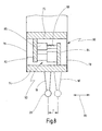
- Fig. 8 shows on the basis of a simplified schematic representation of the basic operation of the probe 60.
- the probe 60 is designed as an active probe.
- the probe 60 has a fixed part 72 and a movable part 74, which are connected to each other via two leaf springs 42, 44.
- the leaf springs 76, 78 form a spring parallelogram, which allows movement of the part 74 in the direction of the arrow 80.
- the stylus 18 can be deflected by a distance T from its rest position.
- the probe 60 is shown schematically in the deflected position.
- the deflection of the stylus 18 relative to the fixed part 72 may be the result of a probing of the measuring object 12.
- the deflection of the stylus 18 is taken into account in the determination of the spatial coordinates of the Tastkugel 20.
- the deflection of the stylus 18 can be generated at an active probe 60 with the aid of a measuring force generator.
- a leg 82, 84 is arranged on the fixed part 72 and on the movable part 74 in each case.
- the legs 82, 84 are parallel to the leaf springs 76, 78 and parallel to each other.
- a sensor 86 shown here with a scale 88
- a measuring force generator or measuring force transducer 90 is arranged between the legs 82, 84.
- the sensor 86 can be a plunger coil, a Hall sensor, a piezoresistive sensor or another sensor, with the aid of which the spatial deflection of the stylus 18 relative to the fixed part 72 can be determined.
- the measuring force generator 90 may be, for example, a plunger coil, by means of which the two legs 82, 84 can be pulled against each other or pushed apart.
- the probe 60 is also connected to the control device 64, so that they can read on the one hand sizes such as the deflection and the probing force and on the other hand can control the measuring force generator 90.
- Fig. 8 allows the probe 60 only a deflection of the stylus 18 in the direction of arrow 46.
- a probe 60 typically allows a corresponding deflection in two other orthogonal directions in space.
- An embodiment of such a probe 60 is for example in the document DE 44 24 225 A1 described.
- the invention is not limited to this particular probe 60 and may be implemented with other sensing or sensing probes of other sensing systems, particularly passive probes.
- a probe 60 or sensor head of in Fig. 8 in a highly simplified manner, as a rule, has a receptacle on which the stylus 18 or another sensor is interchangeably attached.
Description
Die vorliegende Erfindung betrifft ein Verfahren zum Regeln eines Messvorgangs eines Koordinatenmessgeräts zum Vermessen eines Messobjekts, wobei das Koordinatenmessgerät eine Regelungseinrichtung und einen Tastkopf mit einem Taststift aufweist, und wobei eine Relativbewegung zwischen dem Taststift und einer Oberfläche des Messobjekts von der Regelungseinrichtung geregelt wird.The present invention relates to a method for controlling a measuring operation of a coordinate measuring machine for measuring a measuring object, wherein the coordinate measuring machine has a control device and a probe with a stylus, and wherein a relative movement between the stylus and a surface of the measured object is controlled by the control device.
Des Weiteren betrifft die vorliegende Erfindung ein Koordinatenmessgerät zum Vermessen eines Messobjekts, mit einer Regelungseinrichtung und einem Tastkopf, der einen Taststift aufweist, wobei eine Relativbewegung zwischen dem Taststift und einer Oberfläche des Messobjekts von der Regelungseinrichtung geregelt wird.Furthermore, the present invention relates to a coordinate measuring machine for measuring a DUT, with a control device and a probe having a stylus, wherein a relative movement between the stylus and a surface of the measurement object is controlled by the control device.
Ein derartiges Verfahren und ein derartiges Koordinatenmessgerät sind beispielsweise aus der Druckschrift
Dreidimensionale Koordinatenmessgeräte sind im Stand der Technik allgemein bekannt. In industriellen Anwendungen werden sie dazu verwendet, Werkstücke zu vermessen und sie dadurch beispielsweise einer Qualitätskontrolle zu unterziehen. Aber auch in anderen Anwendungsbereichen, beispielsweise im Bereich des "Reverse-Engineering" werden derartige Koordinatenmessgeräte verwendet.Three-dimensional coordinate measuring machines are well known in the art. In industrial applications, they are used to measure workpieces and thereby subject them to quality control, for example. But also in other applications, such as in the field of "reverse engineering" such coordinate measuring machines are used.
Zum Vermessen der Werkstücke werden unterschiedliche Messsysteme verwendet. Üblicherweise sind dies entweder optische Messsysteme, die ein berührungsfreies Vermessen der Werkstücke ermöglichen, oder taktile Messsysteme, bei denen das Werkstück in bestimmten Punkten angetastet wird, um die Koordinaten der angetasteten Punkte des Werkstücks zu erfassen.Different measuring systems are used to measure the workpieces. Usually, these are either optical measuring systems that allow a non-contact measurement of the workpieces, or tactile measuring systems in which the workpiece is scanned at certain points to detect the coordinates of the probed points of the workpiece.
Die vorliegende Erfindung beschäftigt sich mit Koordinatenmessgeräten, die taktile Messsysteme aufweisen. Solch ein Koordinatenmessgerät besitzt einen Tastkopf, der in einem Messraum relativ zu einem Werkstück dreidimensional bewegbar angeordnet ist. Der Tastkopf weist eine Sensorik auf, die einen Taststift beweglich lagert und dazu in der Lage ist, eine Auslenkung des Taststifts relativ zur Tastkopfbasis zu erfassen. Der Taststift weist eine Tastspitze auf, an der ein Tastobjekt, in der Regel eine Tastkugel, vorgesehen ist. Aufgrund der bekannten Geometrie des Taststifts und der bekannten Position des Tastkopfes in dem Messraum kann man mit Hilfe der von der Sensorik erfassten Auslenkung Raumkoordinaten des angetasteten Messpunktes an dem Werkstück bestimmen.The present invention is concerned with coordinate measuring machines which have tactile measuring systems. Such a coordinate measuring machine has a probe which is arranged to be three-dimensionally movable in a measuring space relative to a workpiece. The probe has a sensor that movably supports a stylus and is capable of detecting a deflection of the stylus relative to the probe base. The stylus has a Tastspitze on which a Tastobjekt, usually a Tastkugel, is provided. Due to the known geometry of the stylus and the known position of the probe in the measuring space can be determined using the detected by the sensor deflection spatial coordinates of the probed measuring point on the workpiece.
Zum Vermessen eines Werkstücks sind verschiedene Messarten bekannt. Die Vermessung kann derart erfolgen, dass eine Vielzahl von Punkten einzeln angetastet wird. Ein derartiges Messverfahren ermöglicht beispielsweise das Erfassen von vollständig unbekannten Geometrien, erfordert jedoch aufgrund des einzelnen Antastens jedes Messpunkts einen erhöhten Zeitaufwand.For measuring a workpiece different types of measurement are known. The measurement can be carried out such that a plurality of points is scanned individually. Such a measuring method, for example, makes it possible to detect completely unknown geometries, but requires an increased expenditure of time due to the individual probing of each measuring point.
Daneben sind auch so genannte Scanning-Verfahren bekannt, bei denen der Taststift in Kontakt mit dem zu vermessenden Werkstück entlang dem zu vermessenden Werkstück verfahren wird und so eine Vielzahl von Messpunkten entlang einer Bahn auf der Werkstückoberfläche erfasst. Auf diese Weise ist es möglich, sehr schnell eine hohe Anzahl von Messpunkten zu erfassen. Dafür ist es jedoch notwendig, die Bewegungsbahn des Tastkopfes derart zu regeln, dass sich der Taststift bzw. die Tastkugel ständig in Kontakt mit der Oberfläche des Werkstücks befindet. Hierzu ist in der Regel eine Sollgeometrie der Bahn vorbekannt. Beispielsweise kann bekannt sein, dass der Innendurchmesser einer kreisförmigen Bohrung vermessen werden soll, so dass die Sollgeometrie eine Kreisbahn ist. Die Kenntnis dieser Sollgeometrie erleichtert das Regeln der Bahn des Tastkopfs während des Scanning-Vorgangs, so dass nur anhand der tatsächlichen Abweichung der Messpunkte von der Sollgeometrie eine Nachregelung der Bahn des Tastkopfs zu erfolgen hat.In addition, so-called scanning methods are known in which the stylus in contact with the workpiece to be measured along the zu measuring workpiece and thus detects a plurality of measuring points along a path on the workpiece surface. In this way it is possible to detect a high number of measuring points very quickly. However, it is necessary to control the trajectory of the probe so that the stylus or the probe ball is constantly in contact with the surface of the workpiece. For this purpose, a desired geometry of the web is generally known in the past. For example, it may be known that the inner diameter of a circular bore is to be measured, so that the desired geometry is a circular path. The knowledge of this desired geometry facilitates the regulation of the path of the probe during the scanning process, so that only on the basis of the actual deviation of the measuring points from the desired geometry a readjustment of the trajectory of the probe has to be made.
Des Weiteren sind im Stand der Technik so genannte aktiv messende und so genannte passiv messende Tastköpfe bekannt. Bei den passiv messenden Tastköpfen ist der Taststift im wesentlichen über mechanische Federelemente gelagert. Eine Auslenkung des Taststifts ist somit stets proportional zu einer Federkraft der Lagerung und damit zu einer Antastkraft, mit der der Taststift gegen die Werkstückoberfläche drückt. Während eines Scanning-Vorgangs entlang einer Werkstückoberfläche ist es von Vorteil, wenn sich die Antastkraft nur in einem bestimmten Bereich befindet, um ein übermäßiges Durchbiegen des Taststifts oder eine Beschädigung des Werkstücks zu vermeiden. Da bei passiv messenden Tastköpfen die Antastkraft proportional zu der Auslenkung des Taststifts ist, muss in diesem Fall der Tastkopf bewegt werden, um die Auslenkung des Taststifts und damit die Antastkraft zu ändern. Eine Bewegung des Tastkopfs hat Beschleunigungen und damit Trägheitskräfte zur Folge, was die Regelung eines solchen passiv messenden Tastkopfs erschweren kann.Furthermore, in the prior art so-called active measuring and so-called passive measuring probes are known. In the passive measuring probes of the stylus is mounted substantially on mechanical spring elements. A deflection of the stylus is thus always proportional to a spring force of the bearing and thus to a probing force with which the stylus presses against the workpiece surface. During a scanning operation along a workpiece surface, it is advantageous if the probing force is only in a certain range in order to avoid excessive bending of the stylus or damage to the workpiece. Since with passive measuring probes the probing force is proportional to the deflection of the stylus, in this case, the probe must be moved to change the deflection of the stylus and thus the probing force. A movement of the probe has accelerations and thus inertial forces result, which can complicate the regulation of such a passive measuring probe.
Bei aktiv messenden Tastköpfe kann die Antastkraft unabhängig von der Auslenkung des Taststifts mit Hilfe von Messkraftgebern (zum Beispiel elektromotorische bewegte Tauchspulen oder Piezoelemente) eingestellt werden. Dies ermöglicht es, das Werkstück auch bei großen Auslenkungen des Taststifts, mit einer kleinen und/oder über den Verlauf eines Scanning-Vorgangs gleichbleibenden Antastkraft anzutasten, ohne dass dies eine übermäßige Bewegung, eventuell sogar gar keine Bewegung, des Tastkopfs zur Folge hat.With actively measuring probes, the probing force can be adjusted independently of the deflection of the stylus with the aid of measuring force transmitters (for example electromotive moving plunger coils or piezo elements). This makes it possible, the workpiece even with large deflections of the stylus, with a small and / or consistent over the course of a scanning process Touching probing force without causing excessive movement, possibly even no movement, of the probe.
Die vorliegende Erfindung ist in erster Linie dazu vorgesehen, mit aktiv messenden Tastköpfen verwendet zu werden. Grundsätzlich ist sie jedoch auch bei passiv messenden Tastköpfen anwendbar.The present invention is primarily intended to be used with active sensing probes. In principle, however, it is also applicable to passive measuring probes.
Scanning-Verfahren sind vergleichweise problemlos anwendbar, wenn glatte Oberflächen abzutasten sind. Weisen die abzutastenden Oberflächen jedoch Erhebungen oder Vertiefungen auf, etwa eingefräste Nuten, können Probleme auftreten, wenn sich der Taststift mit seiner Tastkugel an einer Erhebung oder in einer Vertiefung verhakt. Insbesondere Vertiefungen in Werkstückoberflächen können hier ein Problem darstellen. Unter Umständen ist es auch aber gar nicht nötig, die Vertiefung in der Werkstückoberfläche genau zu vermessen, da es lediglich auf den Verlauf der Oberfläche, in die diese Vertiefung eingearbeitet ist, ankommt, beispielsweise darauf, ob die Oberfläche tatsächlich kreisrund oder plan ist.Scanning methods are comparatively easy to use when scanning smooth surfaces. However, if the surfaces to be scanned have protrusions or indentations, such as milled grooves, problems can arise if the stylus hooks with its probe ball on a protrusion or in a depression. In particular recesses in workpiece surfaces can present a problem here. Under certain circumstances, it is also not necessary to precisely measure the depression in the workpiece surface, since it depends only on the course of the surface in which this depression is incorporated, for example, whether the surface is actually circular or planar.
Die Grundbegriffe der Koordinatenmesstechnik und insbesondere Verfahren zu der Auswertung der Messergebnisse sind dem Fachmann bekannt. Hinweise zu bekannten Verfahren der Koordinatenmesstechnik und insbesondere zu Interpolationsverfahren finden sich in dem
Ein häufig auftretendes Problem ist, dass eine Tastkugel des Taststifts, sobald sich der Taststift über eine Vertiefung in einer Oberfläche bewegt, von einer Regelungseinrichtung derart nachgeregelt wird, dass der Taststift in die Vertiefung eintaucht. Die Tastkugel "fällt" quasi in die Vertiefung. Im weiteren Verlauf schlägt der Taststift dann an der gegenüberliegenden Kante der Nut an, wenn die Nut endet. Da der Scanning-Vorgang mit einem bestimmten Vorschub erfolgt, beispielsweise fünf Millimeter pro Sekunde, kann es vorkommen, dass der Taststift nicht mehr schnell genug aus der Nut "herausgehoben" werden kann. In der Folge kann es entweder zu Beschädigungen des Taststiftes kommen, oder aber der Scanning-Vorgang muss abgebrochen werden, damit die Regelungseinrichtung des Koordinatenmessgeräts den Taststift zunächst erst wieder aus der Vertiefung bzw. der Nut befreien kann.A common problem is that a stylus ball of the stylus, as soon as the stylus moves over a recess in a surface, is readjusted by a control device such that the stylus dips into the recess. The probe sphere "falls" into the depression. In the further course of the stylus then hits the opposite edge of the groove when the groove ends. Since the scanning process is done at a certain feed rate, for example, five millimeters per second, the stylus may not can be "lifted out" of the groove more quickly enough. As a result, it can either damage the stylus, or the scanning process must be canceled, so that the control device of the coordinate measuring machine can first release the stylus again from the recess or the groove.
Es wurde daher nach Lösungsmöglichkeiten gesucht, ein derartiges "Eintauchen" des Taststifts in Vertiefungen einer zu vermessenden Oberfläche zu vermeiden.It was therefore sought to find ways to avoid such a "dipping" of the stylus in wells of a surface to be measured.
So schlägt die
Auch in
Es ist eine Aufgabe der vorliegenden Erfindung, eine Möglichkeit zum Scannen einer Werkstückoberfläche mit Vertiefungen bereitzustellen, die ein Scannen auch dann möglich macht, wenn sich an einer Messposition überhaupt kein Werkstück befindet, beispielsweise aufgrund der Vertiefung. Dabei sollen alle bekannten Mess-, Scan- und Interpolationsverfahren ohne Änderungen anwendbar bleiben und vermieden werden, dass sich ein Taststift in der Vertiefung verhakt, auch wenn keine Kenntnis über vorhandene Vertiefungen besteht. Des Weiteren muss erkennbar bleiben, ob ein erfasster Messwert von der tatsächlich gescannten Werkstückoberfläche stammt.It is an object of the present invention to provide a possibility of scanning a workpiece surface with recesses, which makes scanning possible even when there is no workpiece at a measuring position, for example due to the recess. Here are all known Measurement, scanning and interpolation remain applicable without changes and to avoid that a stylus hooks in the depression, even if there is no knowledge of existing wells. Furthermore, it must remain recognizable whether a recorded measured value originates from the actually scanned workpiece surface.
Gemäß einem ersten Aspekt der Erfindung wird daher vorgeschlagen, das eingangs genannte Verfahren mit den Merkmalen des kennzeichnenden Teils des Anspruchs 1 weiterzubilden.According to a first aspect of the invention is therefore proposed to develop the aforementioned method with the features of the characterizing part of claim 1.
Gemäß einem zweiten Aspekt der Erfindung wird vorgeschlagen, das eingangs genannte Koordinatenmessgerät mit den Merkmalen des kennzeichnenden Teils des Anspruchs 8 weiterzubilden.According to a second aspect of the invention, it is proposed to further develop the aforementioned coordinate measuring machine with the features of the characterizing part of claim 8.
Gemäß einem dritten Aspekt der Erfindung wird ein Computerprogramm mit Programmcodemitteln vorgeschlagen, das dazu ausgebildet ist, alle Schritte eines Verfahrens gemäß dem ersten Aspekt der Erfindung auszuführen, wenn das Computerprogramm in der Steuerung eines Koordinatenmessgerätes ausgeführt wird.According to a third aspect of the invention, a computer program with program code means is proposed, which is designed to execute all the steps of a method according to the first aspect of the invention when the computer program is executed in the control of a coordinate measuring machine.
Es werden im Regelungsprozess also virtuelle, tatsächlich am Werkstück nicht vorhandene Oberflächen berücksichtigt, die von einem Benutzer des Koordinatenmessgerätes vorab definiert werden, beispielsweise mit Hilfe einer geeigneten Anwendersoftware vorgegeben werden können. Diese virtuellen Oberflächen können in ihrer Form und Lage weitgehend beliebig im Messraum angeordnet werden und z.B. aus ebenen Flächen, Zylindern oder Kugeln bestehen. Die virtuelle Oberfläche ergänzt und/oder verändert die tatsächlich vorhandene Werkstückoberfläche, und sie bestimmt somit die Bewegungsbahn des Taststiftes relativ zum Werkstück und der tatsächlichen Werkstückoberfläche. Da die Sollgeometrie des zu vermessenden Werkstücks grundsätzlich bekannt ist, ist es vorteilhaft möglich, die virtuelle Oberfläche so zu definieren und in dem Messraum zu platzieren, dass Vertiefungen in der realen Werkstückoberfläche "aufgefüllt" werden. Der Taststift "springt" dann über die Vertiefung, indem er aufgrund der Regelung an der virtuellen Oberfläche entlang geführt wird. In einigen Fällen ist es von Vorteil, wenn die virtuelle Oberfläche in dem Werkstück und somit unter der tatsächlichen Werkstückoberfläche liegt. Soll beispielsweise eine Kugel gescannt werden, könnte die virtuelle Oberfläche eine Kugel mit einem etwas geringeren Radius sein. Befinden sich nun Vertiefungen, wie beispielsweise Nuten, in der tatsächlichen Werkstückoberfläche, werden diese Vertiefungen bzw. Nuten von der virtuellen Oberfläche "überdeckt". Trifft eine Tastkugel des Taststifts dann auf diese virtuelle Oberfläche, werden Regel- und Messgrößen erzeugt, die denen einer tatsächlichen Oberfläche entsprechen. Entsprechend regelt die Regelungseinrichtung die Position der Tastkugel bzw. des Tastkopfs, als ob es sich bei der virtuellen Oberfläche um eine tatsächliche Oberfläche handelt. Eine Tastkugel würde daher nicht bis zum Grund in die Vertiefung eintauchen, sondern auf der virtuellen Oberfläche entlang laufen. Die zu überwindenden Höhenunterschiede sind somit geringer, so dass am Ende einer tatsächlichen Vertiefung die Tastkugel bzw. der Taststift problemlos wieder auf die tatsächliche Werkstückoberfläche gelangen kann. Beim Scannen einer Zahnradgeometrie kann eine vorteilhafte virtuelle Oberfläche einen Hüllkörper bilden, der sich wie eine gedachte Folie über die Spitzen der einzelnen Zähne spannt. Wenn die Regelungseinrichtung den Taststift entlang einer solchen virtuellen Oberfläche bewegt, taucht das Tastobjekt am freien Ende des Taststiftes nicht zwischen die tatsächlich vorhandenen Zähne ein.In the control process, therefore, virtual surfaces that are actually not present on the workpiece are taken into account, which are defined in advance by a user of the coordinate measuring machine, for example, with the aid of suitable user software. These virtual surfaces can be largely arbitrarily arranged in their shape and position in the measuring space and, for example, consist of flat surfaces, cylinders or balls. The virtual surface complements and / or alters the actual workpiece surface, and thus determines the trajectory of the stylus relative to the workpiece and the actual workpiece surface. Because the target geometry of the to be measured Workpiece is basically known, it is advantageously possible to define the virtual surface and place it in the measuring space that recesses are "filled" in the real workpiece surface. The stylus then "jumps" over the depression by being guided along the virtual surface due to the regulation. In some cases, it is advantageous if the virtual surface lies in the workpiece and thus below the actual workpiece surface. For example, if you want to scan a sphere, the virtual surface might be a sphere with a slightly smaller radius. If depressions, such as grooves, are now present in the actual workpiece surface, these depressions or grooves are "covered" by the virtual surface. If a stylus ball of the stylus then hits this virtual surface, control and measured variables are generated which correspond to those of an actual surface. Accordingly, the control device controls the position of the probe ball or of the probe, as if the virtual surface is an actual surface. A probe ball would therefore not dive to the bottom in the depression, but run along the virtual surface. The differences in height to be overcome are thus less, so that at the end of an actual depression the probe ball or stylus can easily get back to the actual workpiece surface. When scanning a gear geometry, an advantageous virtual surface may form an enveloping body that spans over the tips of the individual teeth like an imaginary foil. When the control device moves the stylus along such a virtual surface, the stylus at the free end of the stylus does not dip between the actual teeth.
Die von dem Koordinatenmessgerät vermessene Oberfläche, entlang der die Tastkugel bzw. der Taststift geregelt bewegt wurde, setzt sich somit aus tatsächlich am Werkstück vorhandenen, realen Abschnitten zusammen, die der zu vermessenden Werkstückoberfläche entsprechen, und aus virtuellen Abschnitten, die der Regelungseinrichtung beispielsweise in Form von Geometriedaten vorgegeben werden, die jedoch als reale Oberfläche nicht existieren. Vorzugsweise wird an der Regelungseinrichtung und dem Regelungsalgorithmus des Tastkopfs nichts verändert. Da die virtuellen Oberflächen somit problemlos mit der bereits existierenden Regelungs- und Interpolations-Software eines Koordinatenmessgeräts verwendet werden können, können die virtuellen Oberflächen gescannt und mit realen bzw. tatsächlichen Werkstückoberflächen kombiniert werden.The surface measured by the coordinate measuring machine, along which the probe ball or feeler has been moved in a controlled manner, is thus composed of actual sections which actually correspond to the workpiece and correspond to the workpiece surface to be measured, and of virtual sections which are in the form of the control device, for example are given by geometry data that does not exist as a real surface. Preferably, nothing is changed at the control device and the control algorithm of the probe. Since the virtual surfaces can thus be easily used with the existing control and interpolation software of a CMM, the virtual surfaces can be scanned and combined with real or actual workpiece surfaces.
Prinzipiell macht es keinen Unterschied, ob der Taststift bzw. Tastkopf eine feststehende Oberfläche scannt bzw. an einem feststehenden Messobjekt entlang bewegt wird, oder ob die Oberfläche bzw. das Messobjekt an einem feststehenden Taststift bzw. Tastkopf entlang bewegt wird. Es ist auch möglich, dass sowohl der Taststift bzw. Tastkopf als auch die Oberfläche bzw. das Messobjekt bewegt werden. Maßgeblich ist allein eine Relativbewegung zwischen Messobjekt und Tastkopf. Je nach zu vermessendem Messobjekt kann eine geeignete Anordnung vorgesehen werden. Sollen etwa häufig verschiedene Messobjekte mit unterschiedlichen Formen vermessen werden, ist es von Vorteil, dass Messobjekt stationär anzuordnen und den Taststift zu bewegen. Sollen hingegen nur rotationssymmetrische, weitgehend gleich geformte Messobjekte, etwa Zahnräder, vermessen werden, kann es vorteilhafter sein, den Taststift stationär zu halten und das Messobjekt zu drehen. Auf diese Weise kann die zu bewegende Masse klein gehalten werden.In principle, it makes no difference whether the stylus or probe scans a fixed surface or is moved along a stationary measurement object or whether the surface or the object to be measured is moved along a fixed stylus or probe. It is also possible that both the stylus or probe and the surface or the object to be measured are moved. Decisive is only a relative movement between the object to be measured and the probe. Depending on the measurement object to be measured, a suitable arrangement can be provided. If, for example, different measuring objects with different shapes are to be measured frequently, it is advantageous to arrange the object to be measured stationary and to move the stylus. If, on the other hand, only rotationally symmetrical, largely identically shaped measuring objects, such as toothed wheels, are to be measured, it may be more advantageous to hold the stylus stationary and rotate the test object. In this way, the mass to be moved can be kept small.
Die eingangs gestellte Aufgabe wird somit vollständig gelöst.The object initially posed is thus completely solved.
Gemäß einer bevorzugten Weiterbildung der Erfindung werden Messwerte, die in dem mindestens einen virtuellen Abschnitt erfasst werden, markiert.According to a preferred embodiment of the invention, measured values which are detected in the at least one virtual section are marked.
Da die in den virtuellen Abschnitten erfassten Messwerte nicht tatsächlichen Messwerten der realen Werkstückoberfläche entsprechen, ist es von Vorteil, diese bei der Auswertung der erfassten Raumkoordinaten unberücksichtigt zu lassen. Vorteilhaft werden die Messwerte, die in dem mindestens einen virtuellen Abschnitt erfasst werden, markiert. Diese markierten Messwerte können dann beispielsweise ausgeblendet bzw. maskiert werden, so dass sie bei einer Nachbearbeitung oder Auswertung nicht verwendet werden.Since the measured values recorded in the virtual sections do not correspond to actual measured values of the real workpiece surface, it is advantageous to disregard these when evaluating the acquired spatial coordinates. Advantageously, the measured values which are detected in the at least one virtual section are marked. These selected measurements can then be, for example be hidden or masked so that they are not used in a post-processing or evaluation.
Des Weiteren kann vorgesehen sein, dass der Tastkopf ein aktiv messender Tastkopf ist und die Regelungseinrichtung eine Messkraft des Taststifts regelt, wobei proportional zu einer Eintauchtiefe des Taststifts in den mindestens einen virtuellen Abschnitt eine Gegenkraft auf einen Messkraftgeber des aktiv messenden Tastkopfs beaufschlagt wird.Furthermore, it can be provided that the probe is an actively measuring probe and the control device controls a measuring force of the stylus, wherein a counter force is applied to a measuring force of the active measuring probe proportional to a depth of the stylus in the at least one virtual section.
Auf diese Weise ist es bei aktiven Tastköpfen möglich, die virtuelle Oberfläche, die von einem Anwender oder automatisch festgelegt wurde, in tatsächliche Eingaben in die Regelungseinrichtung des Tastkopfs umzusetzen. Die virtuelle Oberfläche wird als dreidimensionales Vektorfeld erzeugt, wobei das Vektorfeld abhängig von der Positionierung der virtuellen Oberfläche eine bestimmte Lage in dem Messraum einnimmt. Anhand der Lage sind dann die Raumkoordinaten des Messraums bekannt an denen sich die virtuelle Oberfläche befindet. Für jede Raumkoordinate ist dann ein Vektor einer virtuellen Kraft mit seinem Betrag und seiner Richtung festgelegt. Die Richtung weist dabei normal von der Oberfläche der virtuellen Ebene weg. Der Betrag steigt mit zunehmender Tiefe in der virtuellen Oberfläche an, d.h. an der Oberfläche ist er gering und nimmt dann mit zunehmender Tiefe zu. Die vorliegend verwendeten virtuellen Kräfte weisen somit abhängig von den ihnen zugeordneten Raumkoordinaten unterschiedliche Beträge auf. Die virtuelle Oberfläche könnte somit auch als "virtueller Körper" bezeichnet werden. Bewegt sich die Tastkugel nun in eine Punkt mit Raumkoordinaten, die zu der virtuellen Oberfläche gehören, wird die für diese Raumkoordinaten hinterlegte virtuelle Kraft entgegengesetzt zu einer Soll-Antastkraft auf die Soll-Antastkraft beaufschlagt. Für die Regelungseinrichtung des Koordinatenmessgeräts hat dies den Effekt, dass es den Anschein hat, als ob von der virtuellen Oberfläche eine Kraft auf die Tastkugel des Taststifts ausgeübt wird, sobald die Tastkugel die virtuelle Oberfläche "berührt". Auf die Sollwerte der Messkraftgeber wird somit von der Regelungseinrichtung eine Gegenkraft beaufschlagt. Da der Betrag der virtuellen Kräfte, aus denen die virtuelle Oberfläche gebildet ist, mit zunehmender Eintauchtiefe in die virtuelle Oberfläche zunehmen, stellt sich in einer gewissen Eintauchtiefe ein Gleichgewicht zwischen der Soll-Antastkraft und der virtuellen Kraft ein. Ist dieses Gleichgewicht erreicht, taucht die Tastkugel nicht weiter in die virtuelle Ebene ein. Der Tastkopf dringt so nur sehr wenig in die virtuelle Oberfläche ein. Die Lage der virtuellen Ebene ist dann entsprechend so gewählt, dass die Eintauchtiefe der Tastkugel ein "Erklettern" der Nutkante am Ende der Nut ermöglicht.In this way, with active probes, it is possible to translate the virtual surface defined by a user or automatically into actual inputs to the controller of the probe. The virtual surface is generated as a three-dimensional vector field, wherein the vector field assumes a specific position in the measuring space depending on the positioning of the virtual surface. Based on the location then the spatial coordinates of the measuring space are known at which the virtual surface is located. For each space coordinate, a vector of a virtual force is then determined with its magnitude and its direction. The direction points normally away from the surface of the virtual plane. The amount increases with increasing depth in the virtual surface, ie it is low at the surface and then increases with increasing depth. The presently used virtual forces thus have different amounts depending on the space coordinates assigned to them. The virtual surface could thus also be called a "virtual body". If the probe ball now moves to a point with spatial coordinates that belong to the virtual surface, the virtual force stored for these spatial coordinates is acted upon the desired probe force in a manner opposite to a desired probe force. For the coordinate measuring machine control means, this has the effect of giving a force to the tactile ball of the stylus by the virtual surface as soon as the stylus touches the virtual surface. On the setpoints of the measuring force transducer is thus acted upon by the control device, a counter force. Since the amount of virtual forces that make up the virtual surface increases with increasing immersion depth into the virtual surface At a certain depth of immersion, there is a balance between the desired probing force and the virtual force. When this equilibrium is reached, the probe ball does not dive further into the virtual plane. The probe penetrates so very little in the virtual surface. The position of the virtual plane is then selected accordingly so that the immersion depth of the probe ball allows a "climbing" of the groove edge at the end of the groove.
Das voranstehend beschriebene Vorgehen weist gegenüber dem Stand der Technik insbesondere den Vorteil auf, dass eine Lage der Nuten bzw. Vertiefungen in der tatsächlichen Oberfläche des Messobjekts nicht bekannt sein muss. Mittels der virtuelle Oberfläche lässt sich im Messraum ein wahlweise absolut oder relativ zu dem Messobjekt definierter Bereich erzeugen, in den ein Taststift nicht eindringen kann. Aufgrund dieser durch die virtuellen Oberflächen definierten "verbotenen Zonen" im Messbereich ist während eines Scanning-Vorgangs dem Taststift quasi ein "Sicherungsnetz" untergelegt, dass ein Fallen des Taststifts in die Nut verhindert.In contrast to the prior art, the procedure described above has the particular advantage that a position of the grooves or depressions in the actual surface of the test object need not be known. By means of the virtual surface can be generated in the measuring space either an absolute or relative to the measurement object defined area in which a stylus can not penetrate. Due to these "forbidden zones" defined in the measuring area by the virtual surfaces, the stylus is, as it were, underlaid by a "safety net" during a scanning process, which prevents the stylus from falling into the groove.
Alternativ kann sowohl bei dem Verfahren gemäß dem ersten Aspekt der Erfindung als auch bei dem Koordinatenmessgerät gemäß dem zweiten Aspekt der Erfindung vorgesehen sein, dass der Tastkopf ein passiv messender Tastkopf ist und die Regelungseinrichtung eine Auslenkung des Taststifts regelt, wobei proportional zu einer Eintauchtiefe des Taststifts in den mindestens einen virtuellen Abschnitt eine virtuelle Auslenkung auf eine Sollauslenkung des Taststifts beaufschlagt wird.Alternatively, both in the method according to the first aspect of the invention and in the coordinate measuring machine according to the second aspect of the invention may be provided that the probe is a passive measuring probe and the control device controls a deflection of the stylus, which is proportional to a depth of immersion of the stylus in the at least one virtual section a virtual deflection is applied to a desired deflection of the stylus.
Dabei kann bevorzugt vorgesehen sein, dass die virtuelle Auslenkung entgegengesetzt zu der Sollauslenkung gerichtet ist, so dass sich bei einer bestimmten Eintauchtiefe des Taststifts in den mindestens einen virtuellen Abschnitt ein Gleichgewicht zwischen der Sollauslenkung und der virtuellen Auslenkung bzw. ein Gleichgewicht zwischen den Reglervorgaben einstellt.It can preferably be provided that the virtual deflection is directed opposite to the target deflection, so that adjusts a balance between the desired deflection and the virtual deflection or a balance between the controller default at a certain immersion depth of the stylus in the at least one virtual section.
Obwohl das Verfahren gemäß dem ersten Aspekt der Erfindung und das Koordinatenmessgerät gemäß dem zweiten Aspekt der Erfindung besonders für bzw. mit aktiv messenden Tastköpfen geeignet ist, kann es auch auf passiv messende Tastköpfe übertragen werden. Hier sind die virtuellen Oberflächen nicht durch bestimmten Raumkoordinaten zugeordnete virtuelle Kräfte umgesetzt, sondern es wird eine virtuelle Auslenkung auf die Soll-Auslenkung beaufschlagt. Der Betrag der Vektoren der virtuellen Auslenkung steigt ebenfalls mit zunehmender Eintauchtiefe an. Die Richtungen der Vektoren der virtuellen Auslenkungen sind entgegen der Richtung der Soll-Auslenkung gerichtet, so dass sich bei einer bestimmten Eintauchtiefe ein Gleichgewicht zwischen einer entsprechenden virtuellen Auslenkung und der Soll-Auslenkung einstellt. So wird auch hier eine Regelung des Tastkopfs entlang der virtuellen Oberfläche erreicht.Although the method according to the first aspect of the invention and the coordinate measuring machine according to the second aspect of the invention are particularly suitable for actively measuring probes, it can also be applied to passive measuring probes. Here, the virtual surfaces are not implemented by specific space coordinates associated virtual forces, but it is a virtual deflection applied to the target deflection. The amount of virtual deflection vectors also increases with increasing immersion depth. The directions of the vectors of the virtual deflections are directed counter to the direction of the desired deflection, so that at a certain immersion depth, an equilibrium is established between a corresponding virtual deflection and the desired deflection. Thus, a control of the probe along the virtual surface is achieved here.
Den beiden voranstehend für aktive und für passive Tastköpfe beschriebenen Ausführungsformen ist somit gemein, dass die virtuellen Abschnitte durch mindestens eine virtuelle Oberfläche gebildet sind, wobei die mindestens eine virtuelle Oberfläche als Vielzahl von Vektoren, die mit ihrem Betrag und ihrer Richtung jeweils einer bestimmten Raumkoordinate zugeordnet sind, ausgebildet ist.The two embodiments described above for active and passive probes therefore have in common that the virtual sections are formed by at least one virtual surface, wherein the at least one virtual surface is assigned as a multiplicity of vectors whose magnitude and their direction are each assigned to a specific spatial coordinate are, trained.
In einer weiteren Ausgestaltung sowohl des Verfahrens gemäß dem ersten Aspekt der Erfindung als auch des Koordinatenmessgeräts gemäß dem zweiten Aspekt der Erfindung kann vorgesehen sein, dass eine Lageverschiebung einer bekannten Sollgeometrie des Messobjekts bzw. der zu vermessenden Oberfläche während des Messvorgangs entlang des mindestens einen tatsächlichen Abschnitts erkannt wird, und dass eine Anordnung des mindestens einen virtuellen Abschnitts anhand der Lageverschiebung angepasst wird.In a further embodiment of both the method according to the first aspect of the invention and the coordinate measuring machine according to the second aspect of the invention can be provided that a positional shift of a known desired geometry of the measuring object or the surface to be measured during the measuring process along the at least one actual section is detected, and that an arrangement of the at least one virtual section is adjusted based on the positional shift.
Vorgesehen sein kann somit eine dynamische Verschiebung der Lage der mindestens einen virtuellen Oberfläche. Dies ist insbesondere beim Scannen von Werkstücken mit bekannten Sollgeometrien, z.B. einer Ebene oder einem Zylinder, vorteilhaft. Hierbei wird z.B. eine erkannte Lageverschiebung einer Bohrung - d.h. der Mittelpunkt der Bohrung befindet sich nicht an dem angenommenen Ort - nicht nur für eine Nachregelung eines Interpolationsverfahrens - d.h. die Lage der Sollgeometrie wird für das verwendete Interpolationsverfahren angepasst - sondern gleichzeitig auch für die Nachregelung der Lage bzw. Anordnung der virtuellen Oberfläche verändert. Selbstverständlich darf eine Anpassung bzw. Nachregelung von virtuellen Oberflächen nur dann erfolgen, wenn sich die Tastkugel auf einer tatsächlichen bzw. realen Oberfläche befindet und Messwerte herangezogen werden, die auch auf einer tatsächlichen Oberfläche erfasst wurden.Thus, a dynamic shift of the position of the at least one virtual surface can be provided. This is particularly advantageous when scanning workpieces with known desired geometries, eg a plane or a cylinder. In this case, for example, a detected positional shift of a bore - ie the center of the hole is not located at the assumed location - not only for a readjustment of an interpolation method - ie the position of the desired geometry is adjusted for the interpolation method used - but also changed for the readjustment of the position or arrangement of the virtual surface. Of course, an adaptation or readjustment of virtual surfaces may only take place if the probe ball is located on an actual or real surface and measured values are used which were also recorded on an actual surface.
Auf diese Weise ist es möglich, die Lage der virtuellen Elemente bzw. virtuellen Oberflächen an eine tatsächliche Werkstückform während des Messvorgangs anzupassen.In this way it is possible to adapt the position of the virtual elements or virtual surfaces to an actual workpiece shape during the measuring process.
Letztlich kann sowohl bei dem Verfahren gemäß dem ersten Aspekt der Erfindung als auch bei dem Koordinatenmessgerät gemäß dem zweiten Aspekt der Erfindung vorgesehen sein, dass eine geometrische Form der virtuellen Oberfläche einer Ebene oder einem Zylinder oder einer Kugel entspricht.Finally, both in the method according to the first aspect of the invention and in the coordinate measuring machine according to the second aspect of the invention, it can be provided that a geometric shape of the virtual surface corresponds to a plane or a cylinder or a sphere.
Auf diese Weise ist es möglich, die Form der mindestens einen virtuellen Oberfläche an das tatsächliche Werkstück geeignet anzupassen.In this way, it is possible to suitably adapt the shape of the at least one virtual surface to the actual workpiece.
Es versteht sich, dass die vorstehend genannten und die nachstehend noch zu erläuternden Merkmale nicht nur in der jeweils angegebenen Kombination, sondern auch in anderen Kombinationen oder in Alleinstellung verwendbar sind, ohne den Rahmen der vorliegenden Erfindung zu verlassen.It is understood that the features mentioned above and those yet to be explained below can be used not only in the particular combination given, but also in other combinations or in isolation, without departing from the scope of the present invention.
Ausführungsbeispiele der Erfindung werden nachfolgend mit Bezugnahme auf die anliegende Zeichnung erläutert. Es zeigen:
- Fig. 1
- eine schematische Ansicht eines Messvorgangs gemäß einer Ausführungsform des Verfahrens gemäß dem ersten Aspekt der Erfindung,
- Fig. 2
- eine zweite Ausführungsform des Verfahrens,
- Fig. 3a und 3b
- eine dritte Ausführungsform des Verfahrens,
- Fig. 4a bis 4c
- eine vierte Ausführungsform des Verfahrens,
- Fig. 5
- eine fünfte Ausführungsform des Verfahrens,
- Fig. 6a und 6b
- eine sechste Ausführungsform des Verfahrens,
- Fig. 7
- ein Koordinatenmessgerät gemäß dem zweiten Aspekt der Erfindung, und
- Fig. 8
- eine vereinfachte schematische Darstellung eines aktiven Tastkopfs des Koordinatenmessgeräts in
Fig. 7 .
- Fig. 1
- 1 is a schematic view of a measuring process according to an embodiment of the method according to the first aspect of the invention,
- Fig. 2
- a second embodiment of the method,
- Fig. 3a and 3b
- A third embodiment of the method
- Fig. 4a to 4c
- A fourth embodiment of the method,
- Fig. 5
- a fifth embodiment of the method,
- Fig. 6a and 6b
- A sixth embodiment of the method,
- Fig. 7
- a coordinate measuring machine according to the second aspect of the invention, and
- Fig. 8
- a simplified schematic representation of an active probe of the coordinate measuring machine in
Fig. 7 ,
In dem vorliegenden Beispiel ist das Messobjekt 12 eine Platte, die daraufhin überprüft werden soll, ob sie tatsächlich eben ist.In the present example, the
Dazu ist eine Messobjektoberfläche 13 zu vermessen. Anhand der gewonnen Messpunkte kann dann im Rahmen einer Auswertung überprüft werden, ob die Messobjektoberfläche 13 des Messobjekts 12 tatsächlich eben ist.For this purpose, a
Um dieses zu erreichen, wird eine Oberfläche 14 vermessen, deren Zusammensetzung im Folgenden genauer beschrieben wird.To achieve this, a
Die Messobjektoberfläche 13 weist an einigen Stellen Nuten 16 auf. Die Nuten 16 sind lediglich beispielhaft für mögliche Unebenheiten, insbesondere Vertiefungen, in der Messobjektoberfläche 13 dargestellt. Denkbar sind auch alle anderen Arten von Hindernissen, die den Messvorgang beeinträchtigen könnten.The measuring
Es ist ein Taststift 18 vorgesehen, der an seinem einen Ende eine Tastkugel 20 aufweist, mit der die Oberfläche 14 angetastet werden soll. Der Taststift 18 ist in der
Fährt der Taststift 18 nun die Messobjektoberfläche 13 entlang, um diese abzuscannen, wobei sich die Tastkugel 20 in Kontakt mit der Messobjektoberfläche 13 befindet, muss der Taststift 18 die Nuten 16 überqueren. Damit eine Regelung den Taststift 18 während der Durchführung des Verfahrens 10 nicht zu tief in die Nuten 16 eindringen lässt, so dass sich der Taststift 18 mit der Tastkugel 20 eventuell in den Nuten 16 verhakt, ist eine virtuelle Oberfläche 22 vorgesehen, die entsprechend der tatsächlich zu vermessenden Messobjektoberfläche 13 angeordnet ist. Im vorliegenden Beispiel soll festgestellt werden, ob die Messobjektoberfläche 13 tatsächlich eben bzw. plan ist. Entsprechend kann hier vorgesehen sein, dass sich die virtuelle Oberfläche 22 einige Millimeter unterhalb der Messobjektoberfläche 13 parallel zu dieser erstreckt. Mittels derartiger Randbedingungen kann die virtuelle Oberfläche 22 auch automatisch bzw. rechnergestützt angeordnet werden.If the
Die virtuelle Oberfläche 22 ist als Vielzahl von Vektoren 23, die mit ihrem Betrag und ihrer Richtung jeweils einer bestimmten Raumkoordinate (X,Y,Z) zugeordnet sind, ausgebildet. Bei den Vektoren kann es sich abhängig von der Art eines Tastkopfs um virtuelle Kräfte oder virtuelle Vektoren handeln.The
Die virtuelle Oberfläche 22 wird während der Durchführung des Verfahrens 10 behandelt wie eine tatsächliche bzw. reale Messobjektoberfläche 13 des Messobjekts 12. Entsprechend wird der Taststift 18 mit der Tastkugel 20 geregelt, als ob die virtuelle Oberfläche 22 eine tatsächliche Messobjektoberfläche 13 ist. Auf diese Weise kann verhindert werden, dass die Tastkugel 20 zu weit in die Nut 16 eindringt. Die Oberfläche 14, die somit während des Verfahrens 10 von der Tastkugel 20 gescannt wird, setzt sich somit aus der tatsächlichen Messobjektoberfläche 13 und der virtuellen Oberfläche 22 zusammen. Die Oberfläche 14 weist somit tatsächliche Abschnitte 24 und virtuelle Abschnitte 26 auf. Bei einer Auswertung der Messergebnisse ist folglich darauf zu achten, dass nur diejenigen Messergebnisse herangezogen werden, die während der Antastung der tatsächlichen Messobjektoberfläche 13 erfasst wurden. Es werden auch bei Antastung der virtuellen Oberfläche 22 in den virtuellen Abschnitten 26 der Oberfläche 16 Messwerte erlangt, diese entsprechen aber natürlich nicht den realen Gegebenheiten und müssen somit bei einer Auswertung ausgeblendet werden.The
Der Ablauf eines Messvorgangs des Verfahrens 10 beginnt somit in einer Position A des Taststifts 18, in der die Tastkugel 20 die tatsächliche Messobjektoberfläche 13 antastet. Die Tastkugel 20 befindet sich dabei in einem tatsächlichen Abschnitt 24 der Oberfläche 14. Die Tastkugel 20 wird nun entlang einer Vorschubrichtung 28 bewegt, wobei die Vorschubrichtung 28 stets in etwa einer Sollgeometrie der zu vermessenden Messobjektoberfläche 13 folgt. Die Tastkugel 20 drückt dabei in einer Normalenrichtung 30, d.h. senkrecht zu der Vorschubrichtung 28, auf die Messobjektoberfläche 13. Dadurch wirkt eine Antastkraft F zwischen der Tastkugel 20 und der Messobjektoberfläche 13. Bei stehendem Taststift 18 kann die Antastkraft F von der Normalenrichtung 30 abweichen, wie lediglich beispielhaft in der
Tritt die Tastkugel 20 nun von der Messobjektoberfläche 13 in die Nut 16, bewegt sich die Tastkugel 20 um ein gewisses Maß in die Nut, bis sie auf die virtuelle Oberfläche 22 trifft. Die Tastkugel 20 befindet sich nun in dem virtuellen Abschnitt 26 der Oberfläche 14. Für das Verfahren macht es grundsätzlich keinen Unterschied, ob die Tastkugel 20 auf einer realen bzw. tatsächlichen Messobjektoberfläche 13 befindlich ist oder auf der virtuellen Oberfläche 22. Die Eingaben in eine Regelungseinrichtung, die den Taststift 18 regelt, sind dieselben. Trifft die Tastkugel 20 auf die virtuelle Oberfläche 22, erfolgt eine in Normalenrichtung 30 gegen die Tastkugel 20 gerichtete Gegenkraft als Eingabe in eine Regelungseinrichtung. Die Größe der Gegenkraft kann dabei proportional zu einer Eintauchtiefe D der Tastkugel 20 in die virtuelle Oberfläche 22 ausgestaltet sein. Die virtuelle Oberfläche 22 ist gewissermaßen als Raumbereich mit einer Vielzahl von virtuellen Kraftvektoren ausgestaltet, wobei ein Betrag der Kraftvektoren zunimmt, je tiefer man sich in die virtuelle Oberfläche hineinbewegt. Dies hat zur Folge, dass die Tastkugel 20 um ein gewisses - geringes - Maß in die virtuelle Oberfläche "eintaucht", bis die virtuelle Gegenkraft der Soll-Antastkraft entspricht. Die Tastkugel 20 taucht somit nicht vollständig in die Nut 16 hinab, sondern tastet lediglich - auf virtueller Basis - die virtuelle Oberfläche 22 ab. Auf diese Weise durchquert die Tastkugel 20 in der dargestellten Lage B den virtuellen Abschnitt 26.If the
Da die virtuelle Oberfläche 22 nur einige Millimeter unterhalb (in der in
Mittels des beschriebenen Verfahrens 10 ist es problemlos möglich, die Nuten 16 in dem Messobjekt 12 zu durchqueren. Des Weiteren ist es nicht notwendig, die Tastkugel 20 von der tatsächlichen Messobjektoberfläche 13 abzuheben, um die Tastkugel 20 gewissermaßen über die Nuten 16 "springen" zu lassen. Es wird daher die gesamte zu vermessende Messobjektoberfläche 13 abgetastet.By means of the described
In
In den
Ähnlich verhält es sich bei dem in
Ein weiteres Beispiel ist in den
Das Koordinatenmessgerät 46 weist eine Messoberfläche 48 auf, auf der das Messobjekt 12 angeordnet ist. Auf der Messoberfläche 48 ist ein Portal 50 in einer Y-Richtung beweglich gelagert. An dem Portal 50 ist ein Schlitten 52 in einer X-Richtung beweglich gelagert. In dem Schlitten 52 wiederum ist eine Pinole 54 in Z-Richtung verschieblich gelagert.The coordinate measuring
An einem Ende der Pinole 54 befindet sich ein Tastkopf 60, der den Taststift 18 mit der Tastkugel 20 in sich aufnimmt.At one end of the
Auf diese Weise kann der Taststift 18 in beliebiger Richtung an das Messobjekt 12 herangefahren werden und das Messobjekt 12 mit der Tastkugel 20 angetastet werden.In this way, the
Es sind Skalen 56, 57, 58 vorgesehen, entlang derer das Portal 50, der Schlitten 52 und die Pinole 54 bewegt werden. Mittels geeigneter Sensorik kann so anhand der Skalen 56, 57, 58 die Position des Portals 50, des Schlittens 52 und der Pinole 54 bestimmt werden. Der Tastkopf 60 weist eine weitere Sensorik (nicht dargestellt) auf, die aktiv oder passiv messend ausgestaltet sein kann. Mittels dieser Sensorik kann eine Auslenkung des Taststifts 18 relativ zu dem Tastkopf 60 bzw. der Pinole 54 bestimmt werden, so dass auch eine Position der Tastkugel 20 bekannt ist.There are
Das Koordinatenmessgerät 46 weist des Weiteren eine Regelungseinrichtung 64 auf, die beispielsweise als üblicher Computer ausgebildet sein kann. In üblicher Ausgestaltung weist die Regelungseinrichtung 64 dann eine Ausgabeeinrichtung 66 und eine Eingabeeinrichtung 67 auf, so dass ein Benutzer an der Ausgabeeinrichtung 66 Ergebnisse von Vermessungen ablesen oder beispielsweise ein Ablaufprogramm für einen Messvorgang starten kann. Mittels der Eingabeeinrichtung 67 können beispielsweise verschiedene Modifikationen hinsichtlich der Geschwindigkeit des Messvorgangs, der anzutastenden Oberflächen usw. vorgenommen werden.The coordinate measuring
Die Regelungseinrichtung 64 ist dazu in der Lage, das Messobjekt 12 gemäß dem vorstehend beschriebenen Verfahren zu vermessen. Basierend auf der zu vermessenden Messobjektoberfläche 13 ist die Regelungseinrichtung 64 dazu in der Lage, virtuelle Oberflächen 22 automatisch entsprechend anzuordnen, beispielsweise indem virtuelle Oberflächen um ein gewisses Maß beabstandet und parallel zu der zu vermessenden tatsächlichen Messobjektoberfläche 13 angeordnet werden. Beispielsweise kann vorgesehen sein, dass im Falle einer zu vermessenden Kugeloberfläche automatisch eine virtuelle Kugeloberfläche von etwas geringerem Radius mit gleichem Mittelpunkt angeordnet wird, um ein Fallen des Taststifts in eine Vertiefung der zu vermessenden Kugeloberfläche zu verhindern. Ein Fallen in eine Vertiefung kann somit auch ohne Kenntnis über tatsächlich vorhandene Vertiefungen bzw. Nuten erfolgen.The
Alternativ oder kumulativ kann selbstverständlich auch eine Bedieneinrichtung 69 vorgesehen sein, um einen Messvorgang manuell durchzuführen. So kann beispielsweise ein bestimmter Messvorgang angelernt oder bei einem Ausfall der Regelungseinrichtung 64 die Steuerung des Koordinatenmessgeräts 46 manuell übernommen werden.Alternatively or cumulatively, of course, an operating
Die Regelungseinrichtung 64 kann, wie dargestellt, eine Kabelverbindung zu den übrigen Elementen des Koordinatenmessgeräts 46 aufweisen, sie kann aber auch drahtlos verbunden sein. Selbstverständlich kann es auch vorgesehen sein, dass die Regelungseinrichtung 64 ein integraler Bestandteil der übrigen Elemente ist, beispielsweise in der Messoberfläche 48 oder in dem Portal 50 angeordnet ist. Dort können auch die Ausgabeeinrichtung 66 oder die Eingabeeinrichtung 67 angeordnet sein.The
Die Auslenkung des Taststifts 18 relativ zu dem feststehenden Teil 72 kann die Folge einer Antastung des Messobjekts 12 sein. Die die Auslenkung des Taststifts 18 wird bei der Bestimmung der Raumkoordinaten der Tastkugel 20 berücksichtigt. Darüber hinaus kann die Auslenkung des Taststifts 18 bei einem aktiven Tastkopf 60 mit Hilfe eines Messkraftgenerators erzeugt werden. An dem feststehenden Teil 72 und an dem beweglichen Teil 74 ist jeweils ein Schenkel 82, 84 angeordnet. Die Schenkel 82, 84 stehen parallel zu den Blattfedern 76, 78 und parallel zueinander. Zwischen den Schenkeln 82, 84 ist ein Sensor 86 (hier mit einer Skala 88 dargestellt) und ein Messkraftgenerator bzw. Messkraftgeber 90 angeordnet. Der Sensor 86 kann eine Tauchspule, ein Hall-Sensor, ein piezoresistiver Sensor oder ein anderer Sensor sein, mit dessen Hilfe die räumliche Auslenkung des Taststifts 18 relativ zu dem feststehenden Teil 72 bestimmt werden kann. Der Messkraftgenerator 90 kann beispielsweise eine Tauchspule sein, mit deren Hilfe die beiden Schenkel 82, 84 gegeneinander gezogen oder auseinander gedrückt werden können. Der Tastkopf 60 ist entsprechend auch mit der Regelungseinrichtung 64 verbunden, damit diese zum einen Größen wie die Auslenkung und die Antastkraft auslesen kann und zum anderen den Messkraftgenerator 90 steuern kann.The deflection of the
In der vereinfachten Darstellung in
Den einschlägigen Fachleuten ist bekannt, dass ein Tastkopf 60 bzw. Sensorkopf der in
Claims (15)
- A method (10) for controlling a measurement process of a coordinate measuring machine (46) for measuring a measurement object (12), wherein the coordinate measuring machine (46) comprises a controlling device (64) and a feeler head (60) having a feeler pin (18), and wherein a relative movement between the feeler pin (18) and a surface (14) of the measurement object (12) is controlled by the controlling device (64), characterized in that the surface (14) comprises at least one actual section (24), which corresponds to a measurement object surface (13), and at least one virtual section (26) which is formed by at least one virtual surface (22), wherein virtual surfaces (22) not actually present on the workpiece (12) are thus taken into account in the controlling process, wherein , when the feeler pin (18) meets this virtual surface (22), controlling and measurement variables are generated by the controlling device (64) and the position of the feeler head (60) is controlled by the controlling device as if the virtual surface (22) were an actual surface.
- The method as claimed in claim 1, characterized in that the at least one virtual surface (22) being formed as a multitude of vectors (23) which are respectively assigned with their magnitude and their direction to a particular spatial coordinate.
- The method as claimed in claim 1 or 2, characterized in that the feeler head (60) is an actively measuring feeler head (60) and the controlling device (64) controls a measuring force (F) of the feeler pin, a counterforce being applied to a measuring force transducer (90) of the actively measuring feeler head (60) proportionally to a penetration depth of the feeler pin (18) into the at least one virtual section (26).
- The method as claimed in claim 1 or 2, characterized in that the feeler head (60) is a passively measuring feeler head (60) and the controlling device (64) controls an deflection of the feeler pin (18), a virtual deflection being applied to a setpoint deflection of the feeler pin (18) proportionally to a penetration depth (D) of the feeler pin (18) into the at least one virtual section (26).
- The method as claimed in claim 4, characterized in that the virtual deflection is directed oppositely to the setpoint deflection so that, for a particular penetration depth (D) of the feeler pin (18) in the at least one virtual section (26), an equilibrium is set up between the setpoint deflection and the virtual deflection.
- The method as claimed in any of claims 1 to 5, characterized in that a position displacement of a known setpoint geometry of the measurement object (12) is identified during the measurement process along the at least one actual section (24), and in that an arrangement of the at least one virtual section (26) is adapted with the aid of the position displacement.
- The method as claimed in any of claims 1 to 6, characterized in that a geometrical shape of the virtual surface (22) corresponds to a plane or a cylinder or a sphere.
- A coordinate measuring machine (46) for measuring a measurement object (12), having a controlling device (64) and a feeler head (60), which comprises a feeler pin (18), wherein a relative movement between the feeler pin (18) and a surface (14) of the measurement object (12) is controlled by the controlling device (64), characterized in that the surface (14) comprises at least one actual section (24), which corresponds to a measurement object surface (13), and at least one virtual section (26) which is formed by at least one virtual surface (22), wherein virtual surfaces (22) not actually present on the workpiece (12) are thus taken into account in the controlling process, wherein ,when the feeler pin (18) meets this virtual surface (22), controlling and measurement variables are generated by the controlling device (64) and the position of the feeler head (60) is controlled by the controlling device as if the virtual surface (22) were an actual surface.
- The coordinate measuring machine as claimed in claim 8, characterized in that the at least one virtual surface (22) being formed as a multitude of vectors (23) which are respectively assigned with their magnitude and their direction to a particular spatial coordinate.
- The coordinate measuring machine as claimed in claim 8 or 9, characterized in that the feeler head (60) is an actively measuring feeler head (60) and the controlling device (64) controls a measuring force (F) of the feeler pin (18), a counterforce being applied to a measuring force transducer (90) of the actively measuring feeler head (60) proportionally to a penetration depth (X) of the feeler pin (18) into the at least one virtual section.
- The coordinate measuring machine as claimed in claim 8 or 9, characterized in that the feeler head (60) is a passively measuring feeler head (60) and the controlling device (64) controls an deflection of the feeler pin (18), a virtual deflection being applied to a setpoint deflection of the feeler pin (18) proportionally to a penetration depth of the feeler pin (18) into the at least one virtual section.
- The coordinate measuring machine as claimed in claim 11, characterized in that the virtual deflection is directed oppositely to the setpoint deflection so that, for a particular penetration depth (D) of the feeler pin (18) into the at least one virtual section (26), an equilibrium is set up between the setpoint deflection and the virtual deflection.
- The coordinate measuring machine as claimed in any of claims 8 to 12, characterized in that a position displacement of a known setpoint geometry of the measurement object (12) is identified during the measurement process along the at least one actual section (24), and in that an arrangement of the at least one virtual section (26) is adapted with the aid of the position displacement.
- The coordinate measuring machine as claimed in any of claims 8 to 13, characterized in that a geometrical shape of the virtual surface (22) corresponds to a plane or a cylinder or a sphere.
- A computer program comprising program code means, which is designed so as to carry out all the steps of a method (10) as claimed in any of claims 1 to 7 when the computer program is run in a coordinate measuring machine (46).
Priority Applications (1)
| Application Number | Priority Date | Filing Date | Title |
|---|---|---|---|
| EP14164249.6A EP2755095B1 (en) | 2010-02-15 | 2011-02-09 | Method for controlling a measuring process by means of virtual interfaces |
Applications Claiming Priority (3)
| Application Number | Priority Date | Filing Date | Title |
|---|---|---|---|
| DE102010008751A DE102010008751A1 (en) | 2010-02-15 | 2010-02-15 | Method for controlling measuring process of coordinate measuring apparatus for measuring plate, involves controlling movement of stylus by control unit during measuring process along surface area that has actual and virtual portions |
| DE102010012974 | 2010-03-23 | ||
| PCT/EP2011/051895 WO2011098487A1 (en) | 2010-02-15 | 2011-02-09 | Method for controlling a measuring process by means of virtual surfaces |
Related Child Applications (2)
| Application Number | Title | Priority Date | Filing Date |
|---|---|---|---|
| EP14164249.6A Division-Into EP2755095B1 (en) | 2010-02-15 | 2011-02-09 | Method for controlling a measuring process by means of virtual interfaces |
| EP14164249.6A Division EP2755095B1 (en) | 2010-02-15 | 2011-02-09 | Method for controlling a measuring process by means of virtual interfaces |
Publications (2)
| Publication Number | Publication Date |
|---|---|
| EP2537074A1 EP2537074A1 (en) | 2012-12-26 |
| EP2537074B1 true EP2537074B1 (en) | 2014-05-28 |
Family
ID=43805694
Family Applications (2)
| Application Number | Title | Priority Date | Filing Date |
|---|---|---|---|
| EP14164249.6A Active EP2755095B1 (en) | 2010-02-15 | 2011-02-09 | Method for controlling a measuring process by means of virtual interfaces |
| EP11705482.5A Active EP2537074B1 (en) | 2010-02-15 | 2011-02-09 | Method for controlling a measuring process by means of virtual surfaces |
Family Applications Before (1)
| Application Number | Title | Priority Date | Filing Date |
|---|---|---|---|
| EP14164249.6A Active EP2755095B1 (en) | 2010-02-15 | 2011-02-09 | Method for controlling a measuring process by means of virtual interfaces |
Country Status (5)
| Country | Link |
|---|---|
| US (1) | US8745886B2 (en) |
| EP (2) | EP2755095B1 (en) |
| JP (2) | JP5934115B2 (en) |
| CN (1) | CN102906651B (en) |
| WO (1) | WO2011098487A1 (en) |
Families Citing this family (7)
| Publication number | Priority date | Publication date | Assignee | Title |
|---|---|---|---|---|
| JP5934115B2 (en) * | 2010-02-15 | 2016-06-15 | カール ザイス インダストリエル メステクニーク ゲゼルシャフト ミット ベシュレンクテル ハフツング | How to control the measurement process with a virtual surface |
| PT2913729T (en) * | 2014-02-27 | 2019-10-15 | Fidia Spa | Method and system for checking positioning accuracy of a cnc machine |
| CN104308663A (en) * | 2014-10-27 | 2015-01-28 | 湘潭大学 | Method for virtually measuring machining error of profile of cambered-surface cam |
| JP2018520332A (en) * | 2015-05-04 | 2018-07-26 | 株式会社ミツトヨ | Inspection program editing environment providing a collision avoidance area defined by the user |
| WO2017080612A1 (en) * | 2015-11-13 | 2017-05-18 | Hexagon Technology Center Gmbh | Error compensation for coordinate measuring machines using a reference module |
| US10976146B2 (en) * | 2017-05-03 | 2021-04-13 | Dalian University Of Technology | System for shape error in-situ measurement of large-scale torus |
| GB2562489B (en) | 2017-05-16 | 2022-06-22 | Skf Aerospace France | Method of determining wear in a bearing surface |
Family Cites Families (22)
| Publication number | Priority date | Publication date | Assignee | Title |
|---|---|---|---|---|
| JP2758810B2 (en) * | 1992-10-15 | 1998-05-28 | 株式会社ミツトヨ | Shape measurement method |
| DE4326551C2 (en) * | 1993-08-07 | 1997-04-17 | Heidenhain Gmbh Dr Johannes | Calibration procedure for determining and compensating for different contact force ratios in multi-coordinate touch probes |
| DE4336863C2 (en) * | 1993-10-28 | 1998-01-22 | Zeiss Carl Fa | Method for controlling coordinate measuring machines |
| DE4424225A1 (en) | 1994-07-09 | 1996-01-11 | Zeiss Carl Fa | Probe for coordinate measuring machines |
| DE19529574A1 (en) * | 1995-08-11 | 1997-02-13 | Zeiss Carl Fa | Coordinate measuring device with a control that moves the probe head of the measuring device according to target data |
| DE59711570D1 (en) | 1996-12-21 | 2004-06-03 | Zeiss Carl | Method for controlling a coordinate measuring machine and coordinate measuring machine |
| DE19805155B4 (en) * | 1998-02-10 | 2007-09-27 | Mycrona Gesellschaft für innovative Messtechnik mbH | Method for generating control data for coordinate measuring machines |
| JP2001330428A (en) * | 2000-05-23 | 2001-11-30 | Natl Inst Of Advanced Industrial Science & Technology Meti | Evaluation method for measuring error of three- dimensional measuring machine and gage for three- dimensional measuring machine |
| US7693325B2 (en) * | 2004-01-14 | 2010-04-06 | Hexagon Metrology, Inc. | Transprojection of geometry data |
| JP2005257420A (en) * | 2004-03-11 | 2005-09-22 | Sii Nanotechnology Inc | Scanning probe microscope |
| GB0508217D0 (en) * | 2005-04-25 | 2005-06-01 | Renishaw Plc | Method for scanning the surface of a workpiece |
| KR100660415B1 (en) * | 2005-06-07 | 2006-12-22 | 주식회사 아이너스기술 | Method for detecting 3D scanning data using allowable error zone |
| US7805854B2 (en) * | 2006-05-15 | 2010-10-05 | Hexagon Metrology, Inc. | Systems and methods for positioning and measuring objects using a CMM |
| GB0625260D0 (en) * | 2006-12-19 | 2007-01-24 | Renishaw Plc | A method for measuring a workpiece using a machine tool |
| GB0712008D0 (en) * | 2007-06-21 | 2007-08-01 | Renishaw Plc | Apparatus and method of calibration |
| GB0716218D0 (en) * | 2007-08-20 | 2007-09-26 | Renishaw Plc | Measurement path generation |
| CN101871775B (en) * | 2009-04-21 | 2012-09-19 | 鸿富锦精密工业(深圳)有限公司 | Programming system of three coordinate measuring machine and method thereof |
| JP5371532B2 (en) * | 2009-04-23 | 2013-12-18 | 株式会社ミツトヨ | CMM |
| JP5269698B2 (en) * | 2009-06-10 | 2013-08-21 | 株式会社ミツトヨ | Roundness measuring device |
| JP5934115B2 (en) * | 2010-02-15 | 2016-06-15 | カール ザイス インダストリエル メステクニーク ゲゼルシャフト ミット ベシュレンクテル ハフツング | How to control the measurement process with a virtual surface |
| US8701298B2 (en) * | 2011-06-01 | 2014-04-22 | Tesa Sa | Coordinate measuring machine |
| US8756792B2 (en) * | 2011-06-08 | 2014-06-24 | The Boeing Company | Digitally designed shims for joining parts of an assembly |
-
2011
- 2011-02-09 JP JP2012552381A patent/JP5934115B2/en active Active
- 2011-02-09 EP EP14164249.6A patent/EP2755095B1/en active Active
- 2011-02-09 CN CN201180009762.2A patent/CN102906651B/en active Active
- 2011-02-09 WO PCT/EP2011/051895 patent/WO2011098487A1/en active Application Filing
- 2011-02-09 EP EP11705482.5A patent/EP2537074B1/en active Active
-
2012
- 2012-08-13 US US13/572,967 patent/US8745886B2/en active Active
-
2016
- 2016-01-15 JP JP2016006002A patent/JP2016105101A/en active Pending
Also Published As
| Publication number | Publication date |
|---|---|
| US8745886B2 (en) | 2014-06-10 |
| CN102906651B (en) | 2015-01-28 |
| JP2013519870A (en) | 2013-05-30 |
| JP2016105101A (en) | 2016-06-09 |
| US20130036619A1 (en) | 2013-02-14 |
| EP2755095B1 (en) | 2016-04-20 |
| JP5934115B2 (en) | 2016-06-15 |
| CN102906651A (en) | 2013-01-30 |
| EP2537074A1 (en) | 2012-12-26 |
| EP2755095A1 (en) | 2014-07-16 |
| WO2011098487A1 (en) | 2011-08-18 |
Similar Documents
| Publication | Publication Date | Title |
|---|---|---|
| EP2537074B1 (en) | Method for controlling a measuring process by means of virtual surfaces | |
| EP2010864B1 (en) | Scanning a surface using a coordinate measuring machine | |
| DE102013219389A1 (en) | Reduction of errors of a turning device used in determining coordinates of a workpiece or machining a workpiece | |
| WO2016169589A1 (en) | Method and device for determining actual dimensional properties of a measured object | |
| DE102014112396B4 (en) | Procedure for single-point probing of a workpiece and coordinate measuring machine | |
| EP3359913B1 (en) | Monitoring a safety-relevant parameter of a coordinate measuring device | |
| EP2561311B1 (en) | Operation of a coordinate measuring machine or a machine tool | |
| EP3228974B1 (en) | Roughness measuring probe, device with roughness measuring probe and corresponding use | |
| DE102010008751A1 (en) | Method for controlling measuring process of coordinate measuring apparatus for measuring plate, involves controlling movement of stylus by control unit during measuring process along surface area that has actual and virtual portions | |
| EP3255373B1 (en) | Contact measurement on the tooth flank of a gear wheel | |
| DE19809589A1 (en) | Calibrating scanner of electronically-controlled co-ordinate measuring device | |
| DE102013101931B4 (en) | Method and device for measuring a workpiece | |
| DE102015205566A1 (en) | Calibration of a tactile button attached to a moving part of a CMM | |
| EP1893941B1 (en) | Method and device for determining geometric parameters of a conical object to be measured | |
| DE102010011841B4 (en) | Method for validating a measurement result of a coordinate measuring machine | |
| EP3537102B1 (en) | Method and assembly for increasing throughput with sufficient accuracy when measuring workpieces | |
| EP2378239A2 (en) | Device for measuring objects | |
| DE102013210739B3 (en) | Coordinate measuring machine for measuring workpiece, has drive unit that exerts directed force on thrust unit, such that amount, direction and point of application can be chosen and torque acting on measuring unit is specific value | |
| DE102013207116B4 (en) | Coordinate measuring machine and method for controlling a coordinate measuring machine | |
| DE102010018493B4 (en) | Coordinate measuring device for determining spatial coordinates on a measurement object and probe for such a coordinate measuring machine | |
| DE102010026892A1 (en) | Device for measuring objects | |
| DE102017108033A1 (en) | Method for measuring coordinates or properties of a workpiece surface | |
| DE19861469B4 (en) | Calibrating scanner of electronically-controlled co-ordinate measuring device | |
| DE102009034938B4 (en) | Method for commanding a movement system with a measuring device | |
| DE102014102261A1 (en) | Device and method for measuring measurement objects |
Legal Events
| Date | Code | Title | Description |
|---|---|---|---|
| PUAI | Public reference made under article 153(3) epc to a published international application that has entered the european phase |
Free format text: ORIGINAL CODE: 0009012 |
|
| 17P | Request for examination filed |
Effective date: 20120914 |
|
| AK | Designated contracting states |
Kind code of ref document: A1 Designated state(s): AL AT BE BG CH CY CZ DE DK EE ES FI FR GB GR HR HU IE IS IT LI LT LU LV MC MK MT NL NO PL PT RO RS SE SI SK SM TR |
|
| DAX | Request for extension of the european patent (deleted) | ||
| GRAP | Despatch of communication of intention to grant a patent |
Free format text: ORIGINAL CODE: EPIDOSNIGR1 |
|
| INTG | Intention to grant announced |
Effective date: 20131204 |
|
| GRAS | Grant fee paid |
Free format text: ORIGINAL CODE: EPIDOSNIGR3 |
|
| GRAA | (expected) grant |
Free format text: ORIGINAL CODE: 0009210 |
|
| AK | Designated contracting states |
Kind code of ref document: B1 Designated state(s): AL AT BE BG CH CY CZ DE DK EE ES FI FR GB GR HR HU IE IS IT LI LT LU LV MC MK MT NL NO PL PT RO RS SE SI SK SM TR |
|
| REG | Reference to a national code |
Ref country code: GB Ref legal event code: FG4D Free format text: NOT ENGLISH |
|
| REG | Reference to a national code |
Ref country code: CH Ref legal event code: EP |
|
| REG | Reference to a national code |
Ref country code: AT Ref legal event code: REF Ref document number: 670403 Country of ref document: AT Kind code of ref document: T Effective date: 20140615 |
|
| REG | Reference to a national code |
Ref country code: IE Ref legal event code: FG4D Free format text: LANGUAGE OF EP DOCUMENT: GERMAN |
|
| REG | Reference to a national code |
Ref country code: DE Ref legal event code: R096 Ref document number: 502011003233 Country of ref document: DE Effective date: 20140710 |
|
| REG | Reference to a national code |
Ref country code: NL Ref legal event code: VDEP Effective date: 20140528 |
|
| REG | Reference to a national code |
Ref country code: LT Ref legal event code: MG4D |
|
| PG25 | Lapsed in a contracting state [announced via postgrant information from national office to epo] |
Ref country code: GR Free format text: LAPSE BECAUSE OF FAILURE TO SUBMIT A TRANSLATION OF THE DESCRIPTION OR TO PAY THE FEE WITHIN THE PRESCRIBED TIME-LIMIT Effective date: 20140829 Ref country code: LT Free format text: LAPSE BECAUSE OF FAILURE TO SUBMIT A TRANSLATION OF THE DESCRIPTION OR TO PAY THE FEE WITHIN THE PRESCRIBED TIME-LIMIT Effective date: 20140528 Ref country code: FI Free format text: LAPSE BECAUSE OF FAILURE TO SUBMIT A TRANSLATION OF THE DESCRIPTION OR TO PAY THE FEE WITHIN THE PRESCRIBED TIME-LIMIT Effective date: 20140528 Ref country code: CY Free format text: LAPSE BECAUSE OF FAILURE TO SUBMIT A TRANSLATION OF THE DESCRIPTION OR TO PAY THE FEE WITHIN THE PRESCRIBED TIME-LIMIT Effective date: 20140528 Ref country code: NO Free format text: LAPSE BECAUSE OF FAILURE TO SUBMIT A TRANSLATION OF THE DESCRIPTION OR TO PAY THE FEE WITHIN THE PRESCRIBED TIME-LIMIT Effective date: 20140828 |
|
| PG25 | Lapsed in a contracting state [announced via postgrant information from national office to epo] |
Ref country code: HR Free format text: LAPSE BECAUSE OF FAILURE TO SUBMIT A TRANSLATION OF THE DESCRIPTION OR TO PAY THE FEE WITHIN THE PRESCRIBED TIME-LIMIT Effective date: 20140528 Ref country code: RS Free format text: LAPSE BECAUSE OF FAILURE TO SUBMIT A TRANSLATION OF THE DESCRIPTION OR TO PAY THE FEE WITHIN THE PRESCRIBED TIME-LIMIT Effective date: 20140528 Ref country code: LV Free format text: LAPSE BECAUSE OF FAILURE TO SUBMIT A TRANSLATION OF THE DESCRIPTION OR TO PAY THE FEE WITHIN THE PRESCRIBED TIME-LIMIT Effective date: 20140528 Ref country code: SE Free format text: LAPSE BECAUSE OF FAILURE TO SUBMIT A TRANSLATION OF THE DESCRIPTION OR TO PAY THE FEE WITHIN THE PRESCRIBED TIME-LIMIT Effective date: 20140528 |
|
| PG25 | Lapsed in a contracting state [announced via postgrant information from national office to epo] |
Ref country code: PT Free format text: LAPSE BECAUSE OF FAILURE TO SUBMIT A TRANSLATION OF THE DESCRIPTION OR TO PAY THE FEE WITHIN THE PRESCRIBED TIME-LIMIT Effective date: 20140929 |
|
| PG25 | Lapsed in a contracting state [announced via postgrant information from national office to epo] |
Ref country code: CZ Free format text: LAPSE BECAUSE OF FAILURE TO SUBMIT A TRANSLATION OF THE DESCRIPTION OR TO PAY THE FEE WITHIN THE PRESCRIBED TIME-LIMIT Effective date: 20140528 Ref country code: EE Free format text: LAPSE BECAUSE OF FAILURE TO SUBMIT A TRANSLATION OF THE DESCRIPTION OR TO PAY THE FEE WITHIN THE PRESCRIBED TIME-LIMIT Effective date: 20140528 Ref country code: DK Free format text: LAPSE BECAUSE OF FAILURE TO SUBMIT A TRANSLATION OF THE DESCRIPTION OR TO PAY THE FEE WITHIN THE PRESCRIBED TIME-LIMIT Effective date: 20140528 Ref country code: SK Free format text: LAPSE BECAUSE OF FAILURE TO SUBMIT A TRANSLATION OF THE DESCRIPTION OR TO PAY THE FEE WITHIN THE PRESCRIBED TIME-LIMIT Effective date: 20140528 Ref country code: ES Free format text: LAPSE BECAUSE OF FAILURE TO SUBMIT A TRANSLATION OF THE DESCRIPTION OR TO PAY THE FEE WITHIN THE PRESCRIBED TIME-LIMIT Effective date: 20140528 Ref country code: RO Free format text: LAPSE BECAUSE OF FAILURE TO SUBMIT A TRANSLATION OF THE DESCRIPTION OR TO PAY THE FEE WITHIN THE PRESCRIBED TIME-LIMIT Effective date: 20140528 |
|
| PG25 | Lapsed in a contracting state [announced via postgrant information from national office to epo] |
Ref country code: NL Free format text: LAPSE BECAUSE OF FAILURE TO SUBMIT A TRANSLATION OF THE DESCRIPTION OR TO PAY THE FEE WITHIN THE PRESCRIBED TIME-LIMIT Effective date: 20140528 Ref country code: PL Free format text: LAPSE BECAUSE OF FAILURE TO SUBMIT A TRANSLATION OF THE DESCRIPTION OR TO PAY THE FEE WITHIN THE PRESCRIBED TIME-LIMIT Effective date: 20140528 |
|
| REG | Reference to a national code |
Ref country code: DE Ref legal event code: R097 Ref document number: 502011003233 Country of ref document: DE |
|
| PLBE | No opposition filed within time limit |
Free format text: ORIGINAL CODE: 0009261 |
|
| STAA | Information on the status of an ep patent application or granted ep patent |
Free format text: STATUS: NO OPPOSITION FILED WITHIN TIME LIMIT |
|
| 26N | No opposition filed |
Effective date: 20150303 |
|
| REG | Reference to a national code |
Ref country code: DE Ref legal event code: R097 Ref document number: 502011003233 Country of ref document: DE Effective date: 20150303 |
|
| PG25 | Lapsed in a contracting state [announced via postgrant information from national office to epo] |
Ref country code: BE Free format text: LAPSE BECAUSE OF NON-PAYMENT OF DUE FEES Effective date: 20150228 |
|
| PG25 | Lapsed in a contracting state [announced via postgrant information from national office to epo] |
Ref country code: SI Free format text: LAPSE BECAUSE OF FAILURE TO SUBMIT A TRANSLATION OF THE DESCRIPTION OR TO PAY THE FEE WITHIN THE PRESCRIBED TIME-LIMIT Effective date: 20140528 |
|
| PG25 | Lapsed in a contracting state [announced via postgrant information from national office to epo] |
Ref country code: LU Free format text: LAPSE BECAUSE OF FAILURE TO SUBMIT A TRANSLATION OF THE DESCRIPTION OR TO PAY THE FEE WITHIN THE PRESCRIBED TIME-LIMIT Effective date: 20150209 |
|
| REG | Reference to a national code |
Ref country code: CH Ref legal event code: PL |
|
| PG25 | Lapsed in a contracting state [announced via postgrant information from national office to epo] |
Ref country code: MC Free format text: LAPSE BECAUSE OF FAILURE TO SUBMIT A TRANSLATION OF THE DESCRIPTION OR TO PAY THE FEE WITHIN THE PRESCRIBED TIME-LIMIT Effective date: 20140528 Ref country code: LI Free format text: LAPSE BECAUSE OF NON-PAYMENT OF DUE FEES Effective date: 20150228 Ref country code: CH Free format text: LAPSE BECAUSE OF NON-PAYMENT OF DUE FEES Effective date: 20150228 |
|
| REG | Reference to a national code |
Ref country code: IE Ref legal event code: MM4A |
|
| REG | Reference to a national code |
Ref country code: FR Ref legal event code: ST Effective date: 20151030 |
|
| PG25 | Lapsed in a contracting state [announced via postgrant information from national office to epo] |
Ref country code: IE Free format text: LAPSE BECAUSE OF NON-PAYMENT OF DUE FEES Effective date: 20150209 |
|
| PG25 | Lapsed in a contracting state [announced via postgrant information from national office to epo] |
Ref country code: FR Free format text: LAPSE BECAUSE OF NON-PAYMENT OF DUE FEES Effective date: 20150302 |
|
| PG25 | Lapsed in a contracting state [announced via postgrant information from national office to epo] |
Ref country code: IS Free format text: LAPSE BECAUSE OF FAILURE TO SUBMIT A TRANSLATION OF THE DESCRIPTION OR TO PAY THE FEE WITHIN THE PRESCRIBED TIME-LIMIT Effective date: 20140528 |
|
| PG25 | Lapsed in a contracting state [announced via postgrant information from national office to epo] |
Ref country code: MT Free format text: LAPSE BECAUSE OF FAILURE TO SUBMIT A TRANSLATION OF THE DESCRIPTION OR TO PAY THE FEE WITHIN THE PRESCRIBED TIME-LIMIT Effective date: 20140528 |
|
| REG | Reference to a national code |
Ref country code: AT Ref legal event code: MM01 Ref document number: 670403 Country of ref document: AT Kind code of ref document: T Effective date: 20160209 |
|
| PG25 | Lapsed in a contracting state [announced via postgrant information from national office to epo] |
Ref country code: HU Free format text: LAPSE BECAUSE OF FAILURE TO SUBMIT A TRANSLATION OF THE DESCRIPTION OR TO PAY THE FEE WITHIN THE PRESCRIBED TIME-LIMIT; INVALID AB INITIO Effective date: 20110209 Ref country code: SM Free format text: LAPSE BECAUSE OF FAILURE TO SUBMIT A TRANSLATION OF THE DESCRIPTION OR TO PAY THE FEE WITHIN THE PRESCRIBED TIME-LIMIT Effective date: 20140528 Ref country code: BG Free format text: LAPSE BECAUSE OF FAILURE TO SUBMIT A TRANSLATION OF THE DESCRIPTION OR TO PAY THE FEE WITHIN THE PRESCRIBED TIME-LIMIT Effective date: 20140528 Ref country code: AT Free format text: LAPSE BECAUSE OF NON-PAYMENT OF DUE FEES Effective date: 20160209 |
|
| PG25 | Lapsed in a contracting state [announced via postgrant information from national office to epo] |
Ref country code: TR Free format text: LAPSE BECAUSE OF FAILURE TO SUBMIT A TRANSLATION OF THE DESCRIPTION OR TO PAY THE FEE WITHIN THE PRESCRIBED TIME-LIMIT Effective date: 20140528 |
|
| PG25 | Lapsed in a contracting state [announced via postgrant information from national office to epo] |
Ref country code: MK Free format text: LAPSE BECAUSE OF FAILURE TO SUBMIT A TRANSLATION OF THE DESCRIPTION OR TO PAY THE FEE WITHIN THE PRESCRIBED TIME-LIMIT Effective date: 20140528 |
|
| PG25 | Lapsed in a contracting state [announced via postgrant information from national office to epo] |
Ref country code: AL Free format text: LAPSE BECAUSE OF FAILURE TO SUBMIT A TRANSLATION OF THE DESCRIPTION OR TO PAY THE FEE WITHIN THE PRESCRIBED TIME-LIMIT Effective date: 20140528 |
|
| PGFP | Annual fee paid to national office [announced via postgrant information from national office to epo] |
Ref country code: IT Payment date: 20230223 Year of fee payment: 13 Ref country code: GB Payment date: 20230220 Year of fee payment: 13 Ref country code: DE Payment date: 20230216 Year of fee payment: 13 |
|
| P01 | Opt-out of the competence of the unified patent court (upc) registered |
Effective date: 20230525 |