EP2533389A2 - Method for distributing electrical energy in a power network with a number of distribution network cells - Google Patents
Method for distributing electrical energy in a power network with a number of distribution network cells Download PDFInfo
- Publication number
- EP2533389A2 EP2533389A2 EP20120002956 EP12002956A EP2533389A2 EP 2533389 A2 EP2533389 A2 EP 2533389A2 EP 20120002956 EP20120002956 EP 20120002956 EP 12002956 A EP12002956 A EP 12002956A EP 2533389 A2 EP2533389 A2 EP 2533389A2
- Authority
- EP
- European Patent Office
- Prior art keywords
- curve
- total
- distribution network
- consumer
- curves
- Prior art date
- Legal status (The legal status is an assumption and is not a legal conclusion. Google has not performed a legal analysis and makes no representation as to the accuracy of the status listed.)
- Withdrawn
Links
Images

Classifications
-
- H—ELECTRICITY
- H02—GENERATION; CONVERSION OR DISTRIBUTION OF ELECTRIC POWER
- H02J—CIRCUIT ARRANGEMENTS OR SYSTEMS FOR SUPPLYING OR DISTRIBUTING ELECTRIC POWER; SYSTEMS FOR STORING ELECTRIC ENERGY
- H02J3/00—Circuit arrangements for ac mains or ac distribution networks
- H02J3/008—Circuit arrangements for ac mains or ac distribution networks involving trading of energy or energy transmission rights
-
- H—ELECTRICITY
- H02—GENERATION; CONVERSION OR DISTRIBUTION OF ELECTRIC POWER
- H02J—CIRCUIT ARRANGEMENTS OR SYSTEMS FOR SUPPLYING OR DISTRIBUTING ELECTRIC POWER; SYSTEMS FOR STORING ELECTRIC ENERGY
- H02J13/00—Circuit arrangements for providing remote indication of network conditions, e.g. an instantaneous record of the open or closed condition of each circuitbreaker in the network; Circuit arrangements for providing remote control of switching means in a power distribution network, e.g. switching in and out of current consumers by using a pulse code signal carried by the network
- H02J13/00006—Circuit arrangements for providing remote indication of network conditions, e.g. an instantaneous record of the open or closed condition of each circuitbreaker in the network; Circuit arrangements for providing remote control of switching means in a power distribution network, e.g. switching in and out of current consumers by using a pulse code signal carried by the network characterised by information or instructions transport means between the monitoring, controlling or managing units and monitored, controlled or operated power network element or electrical equipment
-
- H—ELECTRICITY
- H02—GENERATION; CONVERSION OR DISTRIBUTION OF ELECTRIC POWER
- H02J—CIRCUIT ARRANGEMENTS OR SYSTEMS FOR SUPPLYING OR DISTRIBUTING ELECTRIC POWER; SYSTEMS FOR STORING ELECTRIC ENERGY
- H02J3/00—Circuit arrangements for ac mains or ac distribution networks
- H02J3/003—Load forecast, e.g. methods or systems for forecasting future load demand
-
- H—ELECTRICITY
- H02—GENERATION; CONVERSION OR DISTRIBUTION OF ELECTRIC POWER
- H02J—CIRCUIT ARRANGEMENTS OR SYSTEMS FOR SUPPLYING OR DISTRIBUTING ELECTRIC POWER; SYSTEMS FOR STORING ELECTRIC ENERGY
- H02J3/00—Circuit arrangements for ac mains or ac distribution networks
- H02J3/38—Arrangements for parallely feeding a single network by two or more generators, converters or transformers
- H02J3/381—Dispersed generators
-
- H—ELECTRICITY
- H02—GENERATION; CONVERSION OR DISTRIBUTION OF ELECTRIC POWER
- H02J—CIRCUIT ARRANGEMENTS OR SYSTEMS FOR SUPPLYING OR DISTRIBUTING ELECTRIC POWER; SYSTEMS FOR STORING ELECTRIC ENERGY
- H02J3/00—Circuit arrangements for ac mains or ac distribution networks
- H02J3/38—Arrangements for parallely feeding a single network by two or more generators, converters or transformers
- H02J3/46—Controlling of the sharing of output between the generators, converters, or transformers
- H02J3/466—Scheduling the operation of the generators, e.g. connecting or disconnecting generators to meet a given demand
-
- H—ELECTRICITY
- H02—GENERATION; CONVERSION OR DISTRIBUTION OF ELECTRIC POWER
- H02J—CIRCUIT ARRANGEMENTS OR SYSTEMS FOR SUPPLYING OR DISTRIBUTING ELECTRIC POWER; SYSTEMS FOR STORING ELECTRIC ENERGY
- H02J2300/00—Systems for supplying or distributing electric power characterised by decentralized, dispersed, or local generation
- H02J2300/20—The dispersed energy generation being of renewable origin
- H02J2300/28—The renewable source being wind energy
-
- Y—GENERAL TAGGING OF NEW TECHNOLOGICAL DEVELOPMENTS; GENERAL TAGGING OF CROSS-SECTIONAL TECHNOLOGIES SPANNING OVER SEVERAL SECTIONS OF THE IPC; TECHNICAL SUBJECTS COVERED BY FORMER USPC CROSS-REFERENCE ART COLLECTIONS [XRACs] AND DIGESTS
- Y02—TECHNOLOGIES OR APPLICATIONS FOR MITIGATION OR ADAPTATION AGAINST CLIMATE CHANGE
- Y02E—REDUCTION OF GREENHOUSE GAS [GHG] EMISSIONS, RELATED TO ENERGY GENERATION, TRANSMISSION OR DISTRIBUTION
- Y02E40/00—Technologies for an efficient electrical power generation, transmission or distribution
- Y02E40/70—Smart grids as climate change mitigation technology in the energy generation sector
-
- Y—GENERAL TAGGING OF NEW TECHNOLOGICAL DEVELOPMENTS; GENERAL TAGGING OF CROSS-SECTIONAL TECHNOLOGIES SPANNING OVER SEVERAL SECTIONS OF THE IPC; TECHNICAL SUBJECTS COVERED BY FORMER USPC CROSS-REFERENCE ART COLLECTIONS [XRACs] AND DIGESTS
- Y04—INFORMATION OR COMMUNICATION TECHNOLOGIES HAVING AN IMPACT ON OTHER TECHNOLOGY AREAS
- Y04S—SYSTEMS INTEGRATING TECHNOLOGIES RELATED TO POWER NETWORK OPERATION, COMMUNICATION OR INFORMATION TECHNOLOGIES FOR IMPROVING THE ELECTRICAL POWER GENERATION, TRANSMISSION, DISTRIBUTION, MANAGEMENT OR USAGE, i.e. SMART GRIDS
- Y04S10/00—Systems supporting electrical power generation, transmission or distribution
- Y04S10/12—Monitoring or controlling equipment for energy generation units, e.g. distributed energy generation [DER] or load-side generation
- Y04S10/123—Monitoring or controlling equipment for energy generation units, e.g. distributed energy generation [DER] or load-side generation the energy generation units being or involving renewable energy sources
-
- Y—GENERAL TAGGING OF NEW TECHNOLOGICAL DEVELOPMENTS; GENERAL TAGGING OF CROSS-SECTIONAL TECHNOLOGIES SPANNING OVER SEVERAL SECTIONS OF THE IPC; TECHNICAL SUBJECTS COVERED BY FORMER USPC CROSS-REFERENCE ART COLLECTIONS [XRACs] AND DIGESTS
- Y04—INFORMATION OR COMMUNICATION TECHNOLOGIES HAVING AN IMPACT ON OTHER TECHNOLOGY AREAS
- Y04S—SYSTEMS INTEGRATING TECHNOLOGIES RELATED TO POWER NETWORK OPERATION, COMMUNICATION OR INFORMATION TECHNOLOGIES FOR IMPROVING THE ELECTRICAL POWER GENERATION, TRANSMISSION, DISTRIBUTION, MANAGEMENT OR USAGE, i.e. SMART GRIDS
- Y04S10/00—Systems supporting electrical power generation, transmission or distribution
- Y04S10/50—Systems or methods supporting the power network operation or management, involving a certain degree of interaction with the load-side end user applications
-
- Y—GENERAL TAGGING OF NEW TECHNOLOGICAL DEVELOPMENTS; GENERAL TAGGING OF CROSS-SECTIONAL TECHNOLOGIES SPANNING OVER SEVERAL SECTIONS OF THE IPC; TECHNICAL SUBJECTS COVERED BY FORMER USPC CROSS-REFERENCE ART COLLECTIONS [XRACs] AND DIGESTS
- Y04—INFORMATION OR COMMUNICATION TECHNOLOGIES HAVING AN IMPACT ON OTHER TECHNOLOGY AREAS
- Y04S—SYSTEMS INTEGRATING TECHNOLOGIES RELATED TO POWER NETWORK OPERATION, COMMUNICATION OR INFORMATION TECHNOLOGIES FOR IMPROVING THE ELECTRICAL POWER GENERATION, TRANSMISSION, DISTRIBUTION, MANAGEMENT OR USAGE, i.e. SMART GRIDS
- Y04S50/00—Market activities related to the operation of systems integrating technologies related to power network operation or related to communication or information technologies
- Y04S50/10—Energy trading, including energy flowing from end-user application to grid
Definitions
- the invention relates to methods for distributing electrical energy in a power network having a plurality of independently routable distribution network cells according to the preamble of claim 1.
- the operator of the physical line network and the provider of electrical energy sometimes do not fall together in a legal entity, so that the physical regulation of the electrical energy flows within a distribution network is essentially independent of the economic parameters and, in particular, the current level of the electricity price, which is increasingly being used as an incentive for consumers to consume excess electrical energy in the event of overcapacity.
- the technical problem arises that the autonomous regulation of the physical current flow in the distribution networks and the self-contained taken separately also independent price or incentive-based indirect influencing of the physical current flow over the BEMIs are not coordinated.
- the large number of BEMIs within a distribution network also do not communicate with one another in such a way that the physical flow of current within the distribution network is as balanced as possible.
- a method of distributing electrical energy in a power network with a plurality of distribution network cells which are preferably all independently managed, and each of which distribution network cell includes a plurality of self-contained electrical load / generator units, the electrical energy from the Remove distribution network cell and / or feed into the distribution network cell, and in each case via a bidirectional communication interface information in the form of price and / or An Ellkurven and in particular also control curves and / or demand and supply curves with a decentralized computing unit exchange, characterized in that each distribution network cell each having a network automaton, the one first plurality of independent calculation units is assigned, each of which each calculation unit is connected via a bidirectional communication interface with a second plurality of consumer / generator units.
- the network device may include, for example, a computer and connected thereto and controlled electrical circuit and control components, which are arranged for example in a preferably in or near the distribution network cell associated transformer in a cabinet or the like.
- the network device may further comprise known sensors and switches, which are arranged, for example, to the consumer / generator units of a distribution network cell and between two distribution network cells, in order to detect the current flow and / or the voltage and / or the frequency in the physical line network and, if necessary, the To change or interrupt current flow between two distribution network cells or to the consumer / generator units via the switches.
- Each of the first plurality of calculation units - which are also referred to below as market vending machines - calculates a predicted market price curve based on external market information and preferably also on the basis of environmental situations such as the expected solar radiation or rainfall and temperature etc., determined on the basis of the predicted market price curve the provisional total price curve associated with the consumer / producer unit, which preferably also includes the network price curve for the amount of electrical energy withdrawn or supplied during a given period of time.
- the overall price curve preferably including the network price curve, ie the price for the passage of the electrical energy through the physical network within the distribution network cell, is supplied by each calculation unit of the respective bidirectional communication interface of the second plurality of associated consumer / generator units, from the preliminary total price curve determines an expected load demand curve or feed curve for the required or offered by the respective consumer / generator unit in the given period electrical power.
- the expected Load requirement / feed-in curve which is also referred to below as the timetable has been calculated, this is sent back to the associated calculation unit.
- the calculation unit which can be configured, for example, as a known computer, eg as a PC or as a server, determines from the expected load demand curves or feed curves of all consumer / generator units assigned to it an estimated total demand curve / total injection curve for the quantity expected or required in the period electrical energy.
- the expected load demand curves / feed curves or total demand curves / total injection curves are preferably each one and the same curve, which differ only by their sign, depending on whether a consumer / generator unit in the given period, eg a complete Day or even just a few hours, just produces energy or consumes such.
- each of the calculation units After each of the calculation units has determined its respective total demand curve / total feed curve for the consumer / generator units associated with it, it transmits to the network operator an estimated cumulative total demand curve / total injection curve from the estimated total demand curves / total injection curves sent to it by the first plurality of calculation units Distribution network cell generated. On the basis of the course of the expected cumulative total demand curve / total feed-in curve during the given period, the network automaton then checks whether the energy flow in the distribution network cell exceeds a predetermined value or not.
- each distribution network cell forms an independent control loop, wherein the control circuits are in turn connected to one another to form an overall system.
- All control loops, as self-optimizing network cells have the same equipment as the elements of a power supply system (generator, consumer, storage, network resources), have the autonomous action capability and, in the external view, provide a source for Energy supply and as a sink for energy reference to adjacent control loops.
- the distribution network cells are controlled according to the invention in such a way that a high degree of independence arises, the energy flow between adjacent distribution network cells within the power network can be reduced. As a result, cost savings are achieved within the distribution network, as further expansion of the distribution network with an increasing proportion of distributed generators such as e.g. Wind power plants or photovoltaic systems, which are known to lead to large fluctuations in the amounts of energy supplied, not, or only to a lesser extent required.
- distributed generators such as e.g. Wind power plants or photovoltaic systems
- the calculation units determine the anticipated total demand curve / total insertion curve by adding the expected load demand curves / feed curves respectively sent to them.
- the anticipated load requirement curves / feed curves of each consumer / generator unit and also the total / total supply curves are preferably in digital form as a data set, and the addition is carried out digitally by summing up the functional values of all anticipated load demand curves / feed curves involved.
- This embodiment of the invention has the advantage that the total demand / total supply curves for a given period even in distribution network cells with several hundred consumer / generator units with the present computers in a very short time by adding the values assigned to a respective time within the predetermined period for the current Load demand, or the provided electrical power, can be calculated.
- the network operator also determines the cumulative estimated total demand curve / total feed-in curve by adding the individual prospective values sent to it by the calculation units Overall demand curves / total injection curves, which are preferably transmitted as digital data records over a known data network.
- the first network operator calculates a corrected preliminary network price curve and transmits it preferably to each of the calculation units in the distribution network cell.
- the adjustment of the network price curve is made by the network operator in such a way that the network fee is increased by a predetermined amount when the demand for electrical energy that is expected to be taken from the consumer / generator units during the period, higher than the maximum allowable value is.
- Each of the calculation units uses the corrected provisional network price curve sent to it to determine a corrected total price curve for the amount of electrical energy that is expected or required during the given period of time and in turn transmits these via the respective bidirectional communication interface to the respectively assigned consumer / generator units.
- each of the bidirectional communication interfaces of the second plurality of consumer / generator units then generates from the corrected total price curve a corrected mandatory demand curve / feed curve for the amount of electrical energy required or to be supplied by the respective consumer / generator unit in the given period of time and then sends it to the associated calculation unit back.
- Each of the calculation units determines from the corrected binding demand curves / supply curves of all consumers / generator units assigned to them a binding total demand curve / overall supply curve for the electrical power expected or to be supplied in the period and preferably transmits this as a data record in digital form to the automatic network device.
- the network automaton then uses the aggregated total demand curve / total feed curve for the distribution network cell preferably from the first plurality of calculation units to transmit it, and preferably monitors and, where appropriate, compensates for the electrical energy flow into the distribution network during the predetermined period of time Basis of the mandatory cumulative total demand curve / total injection curve.
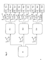
- a power network 1 for distributing electrical energy which is provided via a schematically indicated medium-voltage power network 2 by a large power station not shown in detail, comprises a first distribution network cell 4.1 and further distribution network cells, of which only a further distribution network cell 4.2 partially indicated for the sake of clarity is.
- the distribution network cells 4.1, 4.2 are in the illustrated case distribution network cells for electrical low voltage, which are connected via a respective transformer 6.1, 6.2 to the medium-voltage network 2.
- the invention is not limited thereto, so that the distribution network cells in 4.1, 4.2 on a higher level can also be provided in an analogous manner in the medium-voltage network 2.
- each distribution network cell 4 includes a plurality of consumer / generator units 8, for example, 300 independent consumer / generator units 8.1.1 to 8.nm, each with its own bidirectional communication interface 10, which for the sake of simplicity as part of the respective Consumer / generator unit 8.1.1 to 8.nm is shown, is connected via a corresponding data network with a calculation unit 12.1 to 12.n, which is also referred to below as Tautomat, and the example of a not-shown server data about the respective Electricity tariff, which is valid for the respective consumer / generator unit 8.1.1 to 8.nm, receives.
- the calculation units 12.1 to 12.n are realized, for example, by separate computers or even computer units of a mainframe computer.
- the number of calculation units corresponds to the number of electricity providers multiplied by the number of the respective electricity tariffs, which are provided by the electricity provider and are relevant for the respective consumer / generator unit.
- the consumer / generator units 8.1.1 to 8.nm are preferably independently controlled consumer / generator units, which also use the bidirectional communication interfaces 10 to obtain price information from a central computer (not shown) or via a data network, for example via the Internet, can refer to the time of removal as well as the amount of electrical energy to be taken from them or even the amount of electrical energy they supply to the electrical network of the distribution network cell Depending on the price of electricity and the demand for electrical energy to choose independently from an economic point of view.
- the calculation units 12.1 to 12.n are each connected via data lines not shown in detail for data exchange to a network device 14.1, which is a computing unit and an associated plurality of electrical and electronic circuits, the physical current flow within a distribution network cell 4, for example with the aid of in Fig. 1 monitor only schematically indicated sensors 16 and change by means of a plurality of switches 18 if necessary so that connections of the physical power network within the distribution network cell 4.1 to consumer / generator units and other distribution network cells, here for example distribution network cell 4.2, separated or interconnected.
- each distribution network cell 4.1, 4.2 may also be interconnected for data exchange, for example, to control the flow of electricity from the distribution network cell 4.1 to the distribution network cell 4.2 or, for example, to block in an emergency, depending on whether within the distribution network cell straight there is an excess of, or a need for, electrical energy produced by generator units 8.1.1 to 8.nm.
- Both in the consumer / generator units 8.1.1 to 8.nm with the controller BEMI and in the distribution network cells 4.1, 4.2 as independent units with the regulators Netzautomat 14 and 12.1 to 12n to 12n are physical devices, each taken separately represent an independent independent control loop, so that within each unit as such, the amount of momentarily generated electrical energy and simultaneously consumed electrical energy are already balanced as far as possible against each other.
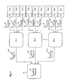
- Each of the calculation units 12.1 to 12.n determines on the basis of the predicted market price curve 20, taking into account the electricity tariff valid for each of the assigned consumer / generator units 8.1.1 to 8.nm, a corresponding preliminary total price curve 22 for the predetermined time period T, which preferably also the network price curve includes for the amount of electrical energy taken or supplied during a given period of time, which then supplies them as a data record via the bidirectional communication interface 10 of the associated consumer / generator unit.
- Each of the bidirectional communication interfaces 10 is calculated as in Fig. 3 for the associated consumer / generator units 8.1.1 to 8.nm from the provisional total price curve 22 Fig. 2 an anticipated load demand / feed curve 24 for the given time period T, which includes the amount of electrical power that is expected or required by the respective consumer / generator unit 8 for that time period T.
- This prospective load requirement / feed-in curve 24 is sent via the bidirectional communication interface 10 of the respective consumer / generator units 8.1.1 to 8.nm to the assigned calculation unit 12.1 to 12.n, which supplies the expected load demand / supply curves 24 of the respective consumer / supply units.
- Summing up generator units 8.1.1 to 8.nm and, preferably, by summing the respective function values, calculate an estimated total demand curve / overall feed-in curve 26.1.bis 26.nm.
- the expected total demand curve / Policy and Charging Program 26.1 to 26.n is then sent in the form of a data set to the automatic network 14, which consists of the data sets for the in Fig. 3 three total demand curves 26.1 to 26.n are calculated by adding a cumulative total demand curve / overall feed-in curve 28, which represents the probable course of the total electric power of all consumers / generator units of the distribution network cell 4 within the time period T, which of course is freely selectable and a full day, eg the following day based on the date of transmission of the record.
- the network automaton also checks whether the energy flow within the distribution network cell 4 reproduced in the predetermined time period T by the course of the cumulative total demand curve / total supply curve 28 exceeds a predetermined maximum value for the electric current flow within the distribution network cell 4. This can be done, for example, by checking whether, for example, the maximum value for the electrical power removed within the predetermined time period T exceeds a maximum value or not.
- the automatic network 14 calculates a corrected provisional network price curve, which provides for an increased grid price for the electrical energy in the event of an expected high power demand within the specified period T.
- the corrected network price is then processed by the network machine 14 in the same way as before with reference to Fig. 2 described as a digital dataset sent to the calculation units 12.1 to 12.n calculated using the new network price curve on the basis of each of their connected consumer / generator unit 8.1.1 to 8.nm relevant electricity tariffs a new corrected total price curve, and this over the bidirectional Send communication interfaces 10 to the associated consumer / generator unit 8.1.1 to 8.nm.
- Each of the bidirectional communication interfaces 10 uses the corrected total price curve to calculate a corrected binding load requirement / supply curve for the amount of energy required or provided by the respective consumer / generator unit 8.1.1 to 8.nm in the predetermined time period T and sends it back to the calculation unit 12.1 to 12.n who prefers it
- a corrected mandatory total requirement curve / total insertion curve is calculated, which in turn is sent to the automatic network 14 in the form of a digital data record from each of the calculation units 12.1.a to 12.n.
- the automatic network 14 adds up the binding total demand curves / total infeed curves and forms a binding cumulative total demand curve / total infeed curve from which measures may be taken to modify the flow of electricity within the distribution network cell such that disturbances in the electrical energy supply, such as surges or unwanted Frequency shifts and imbalances of energy supply and energy, be avoided or compensated.
Abstract
Description
Die Erfindung betrifft Verfahren zur Verteilung von elektrischer Energie in einem Stromnetzwerk mit einer Vielzahl von selbständig führbaren Verteilungsnetzzellen gemäß dem Oberbegriff von Anspruch 1.The invention relates to methods for distributing electrical energy in a power network having a plurality of independently routable distribution network cells according to the preamble of
Bei der Verteilung von elektrischer Energie wird diese in der Regel von zentralen Kraftwerken aus über Hoch- und Mittelspannungsnetze und entsprechende Transformatoren in die Verteilungsnetze mit einer Vielzahl von Niederspannungsnetzen eingespeist, in denen die elektrische Energie von einer Vielzahl von Verbrauchern abgenommen wird. Der Stromfluss ist bei der zuvor beschriebenen Art der zentralen Verteilung der Energie stets von oben nach unten gerichtet, wodurch es in der Vergangenheit keine Probleme gab, den Strom den jeweiligen Bereichen der Verteilungsnetze zuzuleiten, in denen dieser gebraucht wurde.In the distribution of electrical energy, this is usually fed from central power plants via high and medium voltage networks and corresponding transformers in the distribution networks with a variety of low-voltage networks, in which the electrical energy is removed by a variety of consumers. The flow of current is always directed from the top to the bottom in the previously described mode of centralized distribution of energy, which in the past gave rise to no problems in directing the power to the respective areas of the distribution networks in which it was needed.
Mit der ständig wachsenden Zahl von regionalen Energieerzeugern, wie z.B. Blockheizkraftwerken, Photovoltaikanlagen oder Kleinwindanlagen etc., die in den Verteilungsnetzen dezentral zusammen mit den Verbrauchern angeordnet sind, besteht zunehmend das Problem, dass der von den dezentralen Erzeugern produzierte Strom ungeregelt und zufällig insbesondere auch in die Niederspannungsnetze der Verteilungsnetze eingespeist wird.With the ever-increasing number of regional energy producers, such as Combined heat and power plants, photovoltaic systems or small wind turbines, etc., which are arranged in the distribution networks decentralized together with the consumers, there is an increasing problem that the electricity produced by the decentralized producers unregulated and randomly fed in particular in the low-voltage networks of the distribution networks.
Mit der fortschreitenden Nutzung dieser Erzeuger entwickelt sich ein bidirektionaler Energiefluss zwischen übergeordneten Stromnetzen und dem Verteilungsnetz sowie zwischen Verteilungsnetz und den Liegenschaften der Netznutzer. Der Einfluss dieses bidirektionalen Flusses im Netz wird so relevant, beispielsweise durch Spannungsverletzungen, wenn zu hohe Leistungen von Photovoltaikanlagen in Bereichen des Verteilungsnetzes eingespeist werden, ohne dass genügend Verbraucher in der gleichen Region diese Leistung benötigen. Hierdurch wird ein aktives Management dezentraler Anlagen erforderlich. Die aktuell unkontrollierte Einspeisung im dezentralen Bereich ist durch ein dezentrales Energiemanagement zu überwinden.With the progressive use of these generators, a bi-directional flow of energy is developing between higher-level power grids and the distribution network as well as between the distribution network and the grid users' properties. The influence of this bidirectional flow in the grid becomes so relevant, for example due to voltage violations, when too high power of photovoltaic systems are fed into areas of the distribution network without enough consumers in the same region needing this power. This makes active management more decentralized Facilities required. The currently uncontrolled feed-in in the decentralized area must be overcome by decentralized energy management.
Hinzu kommt, dass der Betreiber des physikalischen Leitungsnetzes und der Anbieter der elektrischen Energie in einigen Ländern, wie beispielsweise Deutschland, mitunter nicht in einer juristischen Person zusammen fallen, so dass die physikalische Regelung der elektrischen Energieflüsse innerhalb eines Verteilungsnetzes im Wesentlichen unabhängig von den wirtschaftlichen Größen, wie insbesondere der aktuellen Höhe des Strompreises, ist, der für die Verbraucher zunehmend als Anreiz herangezogen wird, die überschüssige elektrische Energie im Falle einer Überkapazität zu verbrauchen.In addition, in some countries, such as Germany, the operator of the physical line network and the provider of electrical energy sometimes do not fall together in a legal entity, so that the physical regulation of the electrical energy flows within a distribution network is essentially independent of the economic parameters and, in particular, the current level of the electricity price, which is increasingly being used as an incentive for consumers to consume excess electrical energy in the event of overcapacity.
Weiterhin ist es bekannt, den Energiefluss innerhalb von kleineren selbstständigen Verbraucher-/Erzeugereinheiten selbständig zu regeln, wobei die lokalen Erzeuger-/Verbrauchereinheiten, wie z.B. einzelne Haushalte oder gewerbliche oder kommerzielle Objekte als Liegenschaften der Netznutzer, über ein bidirektionales Energiemanagement-Interface - das auch als BEMI bezeichnet wird - an ein Niederspannungsnetz angeschlossen sind und die Informationen über den geplanten Bedarf an elektrischer Energie mit einem zentralen Rechner über ein Datennetz austauschen, um die elektrische Energie nach Möglichkeit dann zu beziehen, wenn der Preis für diese am günstigsten ist.Furthermore, it is known to self-regulate the flow of energy within smaller self-contained consumer / generator units, with the local producer / consumer units, such as e.g. individual households or commercial or commercial properties as properties of network users, connected to a low-voltage network via a bidirectional energy management interface - also referred to as BEMI - and exchanging the information about the planned demand for electrical energy with a central computer via a data network, to obtain the electrical energy if possible, when the price is best for this.
In diesem Zusammenhang sind aus der europäischen Patentanmeldung
Anders ausgedrückt ergibt sich durch die oftmals durch gesetzliche Vorschriften vorgegebene Trennung der Betreiber des physikalischen Leitungsnetzes und der Stromanbieter, die die elektrische Energie zu einem jeweiligen Marktpreis anbieten, das technische Problem, dass die für sich genommene selbständige Regelung des physikalischen Stromfluss in den Verteilungsnetzen und die für sich genommene ebenfalls selbständige preis- oder anreizbasierte indirekte Beeinflussung des physikalischen Stromflusses über die BEMIs nicht aufeinander abgestimmt sind. Hinzu kommt, dass die Vielzahl von BEMIs innerhalb eines Verteilungsnetzes auch untereinander nicht dahingehend miteinander kommunizieren, dass der physikalische Stromfluss innerhalb des Verteilungsnetzes möglichst ausgeglichen ist. Hierdurch ergeben sich insbesondere bei einer zunehmenden Anzahl von BEMIs, die elektrische Energie zu variablen, nicht von vorn herein festgelegten Zeitpunkten in die Niederspannungsbereiche der Verteilungsnetze einspeisen, unerwünschte gleichzeitige Schwankungen der Energieflüsse innerhalb der Niederspannungsbereiche der Verteilungsnetze, die mitunter zu störenden Spannungsschwankungen oder gar zu Beschädigungen von elektrischen Geräten, die in den betreffenden Verteilungsnetzbereichen betrieben werden, führen können. Zusätzlich führt der hohe Anteil dezentraler Erzeugungsanlagen zu in verschiedenen Niederspannungsbereichen der Verteilungsnetze unterschiedlichen Verletzungen der Stromqualität, denen mit unterschiedlichen Maßnahmen zu begegnen ist.In other words, due to the separation, which is often stipulated by legal regulations, the operators of the physical line network and the electricity providers who offer the electrical energy at a particular market price, the technical problem arises that the autonomous regulation of the physical current flow in the distribution networks and the self-contained taken separately also independent price or incentive-based indirect influencing of the physical current flow over the BEMIs are not coordinated. In addition, the large number of BEMIs within a distribution network also do not communicate with one another in such a way that the physical flow of current within the distribution network is as balanced as possible. This results in particular in an increasing number of BEMIs that feed electrical energy to variable, not fixed from the outset times in the low voltage areas of the distribution networks, unwanted simultaneous fluctuations in energy flows within the low voltage areas of the distribution networks, which sometimes disturbing voltage fluctuations or even damage of electrical equipment operating in the distribution network areas concerned. In addition, the high proportion of decentralized generation plants leads to different power quality violations in different low-voltage areas of the distribution networks, which have to be tackled with different measures.
Die Grenzen der zentralen Steuerbarkeit und Kontrolle im Verteilungsnetz werden mit der oben beschriebenen Situation überschritten. Um die weitere Steuerbarkeit zu gewährleisten, ist Komplexität wieder zu reduzieren. Die Reduktion von Komplexität kann durch selbständige, aber gleichzeitig zum Gesamtsystem verbundene Strukturen, die intelligent und synergetisch handeln, erreicht werden. Deshalb wird in verschiedenen Ansätzen die Gliederung von Netzbereichen in Netzzellen vorgeschlagen. Netzzellen, beispielsweise im Niederspannungsbereich, sogenannte Verteilungsnetzzellen, können insbesondere die oben geschilderten Problematiken lösen. Das Verfahren kann jedoch auch auf anderen Spannungsebenenen des Verteilungsnetzes umgesetzt werden. Aktuell sind dabei hierarchische und netzwerkartige Verbindungsansätze der selbständigen Steuerungsstrukturen für ein dezentrales Energiemanagement in selbst organisierenden Netzzellen bekannt, die im Sinne einer hohen Synergie im Gesamtsystem aber immer von Rahmenbedingungen aus zentralen Netzführungsinstanzen ausgehen. Gemeinsam ist den verschiedenen Ansätzen der Gedanke eines dezentraleren Energiemanagements. Zielstellung des beschriebenen Verfahrens ist es deshalb, einen zellularen Netzbetrieb mit Verteilungsnetzzellen mit verteilter Automatisierung zu ermöglichen.The limits of central controllability and control in the distribution network are exceeded with the situation described above. To ensure further controllability, complexity has to be reduced again. The reduction of complexity can be achieved by independent, but at the same time connected to the overall system structures that act intelligently and synergistically. Therefore, the outline of network areas in network cells is proposed in various approaches. Network cells, for example in the low-voltage range, so-called distribution network cells, can in particular solve the above-described problems. However, the method can also be implemented at other voltage levels of the distribution network. Currently, hierarchical and network-like approaches to the connection of the independent control structures for a decentralized energy management in self-organizing network cells are known, which, however, in the sense of high synergy in the overall system, are always based on framework conditions from central network management authorities. Common to the different approaches is the idea of a more decentralized energy management. The aim of the method described is therefore to enable cellular network operation with distributed network cells with distributed automation.
Demgemäß ist es eine Aufgabe der vorliegenden Erfindung, ein Verfahren zu schaffen, mit welchem sich der Energiefluss innerhalb einer Verteilungsnetzzelle eines elektrischen Stromnetzes, die eine Vielzahl von selbständigen elektrischen Verbraucher-/Erzeugereinheiten enthält, welche jeweils über eine bidirektionale Kommunikationsschnittstelle Informationen in Form von Preis- und/oder Anreizkurven mit einer dezentralen Berechnungseinheit austauschen und elektrische Energie in Abhängigkeit davon aus der Verteilungsnetzzelle entnehmen und/oder in die Verteilungsnetzzelle einspeisen, auch bei größeren Schwankungen zwischen eingespeister und entnommener elektrischer Energie in effizienter Weise regeln lässt.Accordingly, it is an object of the present invention to provide a method with which the energy flow within a distribution network cell of an electrical power network, which contains a plurality of independent electrical consumer / generator units, each of which receives information in the form of price via a bidirectional communication interface. and / or switch incentive curves with a decentralized calculation unit and remove electrical energy as a function of it from the distribution network cell and / or feed into the distribution network cell, even with larger fluctuations between fed and withdrawn electrical energy can be controlled in an efficient manner.
Diese Aufgabe wird erfindungsgemäß durch die Merkmale von Anspruch 1 gelöst.This object is achieved by the features of
Gemäß der Erfindung zeichnet sich ein Verfahren zur Verteilung von elektrischer Energie in einem Stromnetzwerk mit einer Vielzahl von Verteilungsnetzzellen, die bevorzugt allesamt selbständig geführt werden, und von denen eine jede Verteilungsnetzzelle eine Vielzahl von selbständigen elektrischen Verbraucher-/Erzeugereinheiten enthält, die elektrische Energie aus der Verteilungsnetzzelle entnehmen und/oder in die Verteilungsnetzzelle einspeisen, und die jeweils über eine bidirektionale Kommunikationsschnittstelle Informationen in Form von Preis- und/oder Anreizkurven sowie insbesondere auch Steuerkurven und/oder Bedarfs- und Bereitstellungskurven mit einer dezentralen Berechnungseinheit austauschen, dadurch aus, dass jede Verteilungsnetzzelle jeweils einen Netzautomaten aufweist, dem eine erste Vielzahl von eigenständigen Berechnungseinheiten zugeordnet ist, von denen eine jede Berechnungseinheit jeweils über eine bidirektionale Kommunikationsschnittstelle mit einer zweiten Vielzahl von Verbraucher-/Erzeugereinheiten verbunden ist. Der Netzautomat kann beispielsweise ein Rechner und mit diesem verbundene und angesteuerte elektrische Schaltungs- und Regelungskomponenten umfassen, die z.B. in einem bevorzugt im oder nahe dem einer Verteilungsnetzzelle zugeordneten Transformator in einem Schaltschrank oder dergleichen angeordnet sind. Der Netzautomat kann weiterhin bekannte Sensoren und Schalter, die z.B. zu den Verbraucher-/Erzeugereinheiten einer Verteilungsnetzzelle sowie zwischen zwei Verteilungsnetzzellen angeordnet sind, umfassen, um den Stromfluss und/oder die Spannung und/oder die Frequenz im physikalischen Leitungsnetz zu erfassen und bei Bedarf den Stromfluss zwischen zwei Verteilungsnetzzellen oder zu den Verbraucher/Erzeugereinheiten über die Schalter zu verändern oder zu unterbrechen.According to the invention, a method of distributing electrical energy in a power network with a plurality of distribution network cells, which are preferably all independently managed, and each of which distribution network cell includes a plurality of self-contained electrical load / generator units, the electrical energy from the Remove distribution network cell and / or feed into the distribution network cell, and in each case via a bidirectional communication interface information in the form of price and / or Anreizkurven and in particular also control curves and / or demand and supply curves with a decentralized computing unit exchange, characterized in that each distribution network cell each having a network automaton, the one first plurality of independent calculation units is assigned, each of which each calculation unit is connected via a bidirectional communication interface with a second plurality of consumer / generator units. The network device may include, for example, a computer and connected thereto and controlled electrical circuit and control components, which are arranged for example in a preferably in or near the distribution network cell associated transformer in a cabinet or the like. The network device may further comprise known sensors and switches, which are arranged, for example, to the consumer / generator units of a distribution network cell and between two distribution network cells, in order to detect the current flow and / or the voltage and / or the frequency in the physical line network and, if necessary, the To change or interrupt current flow between two distribution network cells or to the consumer / generator units via the switches.
Jede der ersten Vielzahl von Berechnungseinheiten - die nachfolgend auch als Marktautomaten bezeichnet werden - errechnet eine prognostizierte Marktpreiskurve auf Basis externer Marktinformationen und bevorzugt auch auf Basis der Umweltsituationen wie z.B. der voraussichtlichen Sonneneinstrahlung oder der Regenmenge und Temperatur etc., ermittelt auf Basis der prognostizierten Marktpreiskurve eine der Verbraucher-/Erzeugereinheit zugeordnete vorläufige Gesamtpreiskurve, die bevorzugt auch die Netzpreiskurve für die während eines vorgegebenen Zeitraums entnommene oder eingespeiste Menge an elektrischer Energie mit einschließt. Die Gesamtpreiskurve, unter bevorzugtem Einschluss der Netzpreiskurve, d.h. des Preises für die Durchleitung der elektrischen Energie durch das physikalische Leitungsnetz innerhalb der Verteilungsnetzzelle, wird von jeder Berechnungseinheit der jeweiligen bidirektionale Kommunikationsschnittstelle der zweiten Vielzahl von zugeordneten Verbraucher-/Erzeugereinheiten zugeführt, die aus der vorläufigen Gesamtpreiskurve eine voraussichtliche Lastbedarfskurve oder Einspeisekurve für die von der jeweiligen Verbraucher-/Erzeugereinheit in dem vorgegebenen Zeitraum benötigte oder angebotene elektrische Leistung ermittelt. Nachdem die bidirektionale Kommunikationsschnittstelle die voraussichtliche Lastbedarfs/Einspeisekurve, die nachfolgend auch als Fahrplan bezeichnet wird, errechnet hat, wird diese zurück an die zugehörige Berechnungseinheit übersandt. Die Berechnungseinheit, die beispielsweise als bekannter Rechner, z.B. als PC oder auch als Server ausgestaltet sein kann, bestimmt aus den voraussichtlichen Lastbedarfskurven oder Einspeisekurven aller ihr zugeordneten Verbraucher-/Erzeugereinheiten eine voraussichtliche Gesamtbedarfskurve/Gesamteinspeisekurve für die in dem Zeitraum voraussichtlich benötigte oder gelieferte Menge an elektrischer Energie. Bei den voraussichtlichen Lastbedarfskurven/Einspeisekurven bzw. Gesamtbedarfskurven/Gesamteinspeisekurven handelt es sich vorzugsweise jeweils um ein und dieselbe Kurve, die sich lediglich durch ihr Vorzeichen voneinander unterscheiden, je nach dem, ob eine Verbraucher-/Erzeugereinheit in dem vorgegebenen Zeitraum, der z.B. einen vollständigen Tag oder auch nur einige Stunden umfassen kann, gerade Energie produziert oder aber solche verbraucht.Each of the first plurality of calculation units - which are also referred to below as market vending machines - calculates a predicted market price curve based on external market information and preferably also on the basis of environmental situations such as the expected solar radiation or rainfall and temperature etc., determined on the basis of the predicted market price curve the provisional total price curve associated with the consumer / producer unit, which preferably also includes the network price curve for the amount of electrical energy withdrawn or supplied during a given period of time. The overall price curve, preferably including the network price curve, ie the price for the passage of the electrical energy through the physical network within the distribution network cell, is supplied by each calculation unit of the respective bidirectional communication interface of the second plurality of associated consumer / generator units, from the preliminary total price curve determines an expected load demand curve or feed curve for the required or offered by the respective consumer / generator unit in the given period electrical power. After the bidirectional communication interface the expected Load requirement / feed-in curve, which is also referred to below as the timetable has been calculated, this is sent back to the associated calculation unit. The calculation unit, which can be configured, for example, as a known computer, eg as a PC or as a server, determines from the expected load demand curves or feed curves of all consumer / generator units assigned to it an estimated total demand curve / total injection curve for the quantity expected or required in the period electrical energy. The expected load demand curves / feed curves or total demand curves / total injection curves are preferably each one and the same curve, which differ only by their sign, depending on whether a consumer / generator unit in the given period, eg a complete Day or even just a few hours, just produces energy or consumes such.
Nachdem jede der Berechnungseinheiten ihre jeweilige Gesamtbedarfskurve/Gesamteinspeisekurve für die ihr zugeordneten Verbraucher-/Erzeugereinheiten bestimmt hat, übermittelt sie diese an den Netzautomaten, der aus den ihm von der ersten Vielzahl von Berechnungseinheiten übersandten voraussichtlichen Gesamtbedarfskurven/Gesamteinspeisekurven eine voraussichtliche kumulierte Gesamtbedarfskurve/Gesamteinspeisekurve für die Verteilungsnetzzelle erzeugt. Anhand des Verlaufs der voraussichtlichen kumulierten Gesamtbedarfskurve/Gesamteinspeisekurve während des vorgegebenen Zeitraums überprüft der Netzautomat dann, ob der Energiefluss in der Verteilungsnetzzelle einen vorgegebenen Wert überschreitet oder nicht.After each of the calculation units has determined its respective total demand curve / total feed curve for the consumer / generator units associated with it, it transmits to the network operator an estimated cumulative total demand curve / total injection curve from the estimated total demand curves / total injection curves sent to it by the first plurality of calculation units Distribution network cell generated. On the basis of the course of the expected cumulative total demand curve / total feed-in curve during the given period, the network automaton then checks whether the energy flow in the distribution network cell exceeds a predetermined value or not.
Die Erfindung besitzt den Vorteil, dass jede Verteilungsnetzzelle einen eigenständigen Regelkreis bildet, wobei die Regelkreise wiederum untereinander zu einem Gesamtsystem verbunden sind. Alle Regelkreise besitzen als selbstoptimierende Netzzellen eine analoge Ausstattung mit den Elementen eines Energieversorgungssystem (Erzeuger, Verbraucher, Speicher, Netzbetriebsmittel), verfügen über die Fähigkeit zur autonomen Handlung und stellen sich in der Außensicht als Quelle für Energieeinspeisung sowie auch als Senke für Energiebezug zu benachbarten Regelkreisen dar.The invention has the advantage that each distribution network cell forms an independent control loop, wherein the control circuits are in turn connected to one another to form an overall system. All control loops, as self-optimizing network cells, have the same equipment as the elements of a power supply system (generator, consumer, storage, network resources), have the autonomous action capability and, in the external view, provide a source for Energy supply and as a sink for energy reference to adjacent control loops.
Da die Verteilungsnetzzellen erfindungsgemäß derart geregelt werden, dass ein hohes Maß an Selbständigkeit entsteht, kann der Energiefluss zwischen benachbarten Verteilungsnetzzellen innerhalb des Stromnetzes reduziert werden. Damit werden innerhalb des Verteilungsnetzes Kostenersparnisse erzielt, da ein weiterer Ausbau des Verteilungsnetzes bei einem steigenden Anteil an dezentralen Erzeugern wie z.B. Windkraftwerken oder Photovoltaikanlagen, welche bekannter Maßen zu starken Schwankungen der eingespeisten Energiemengen führen, nicht, oder nur in einem geringeren Umfang erforderlich werden.Since the distribution network cells are controlled according to the invention in such a way that a high degree of independence arises, the energy flow between adjacent distribution network cells within the power network can be reduced. As a result, cost savings are achieved within the distribution network, as further expansion of the distribution network with an increasing proportion of distributed generators such as e.g. Wind power plants or photovoltaic systems, which are known to lead to large fluctuations in the amounts of energy supplied, not, or only to a lesser extent required.
Nach einem weiteren der Erfindung zugrunde liegenden Gedanken ermitteln die Berechnungseinheiten die voraussichtliche Gesamtbedarfskurve/Gesamteinspeisekurve durch Addition der ihnen jeweils übersandten voraussichtlichen Lastbedarfskurven/ Einspeisekurven. Hierbei liegen die voraussichtlichen Lastbedarfskurven/Einspeisekurven jeder Verbraucher-/ Erzeugereinheit und auch die Gesamtbedarfs/Gesamteinspeisekurven bevorzugt in digitaler Form als Datensatz vor, und die Addition wird auf digitalem Wege durch Aufsummieren der Funktionswerte aller beteiligten voraussichtlichen Lastbedarfskurven/Einspeisekurven vorgenommen. Diese Ausführungsform der Erfindung besitzt den Vorteil, dass sich die Gesamtbedarfs/Gesamteinspeisekurven für einen vorgegebenen Zeitraum selbst bei Verteilungsnetzzellen mit mehreren einhundert Verbraucher-/Erzeugereinheiten mit den heutigen Rechnern in kürzester Zeit durch Aufaddieren der einem jeweiligen Zeitpunkt innerhalb des vorgegebenen Zeitraums zugeordneten Werte für den momentanen Lastbedarf, bzw. die bereit gestellte elektrische Leistung, errechnen lassen.According to another idea on which the invention is based, the calculation units determine the anticipated total demand curve / total insertion curve by adding the expected load demand curves / feed curves respectively sent to them. In this case, the anticipated load requirement curves / feed curves of each consumer / generator unit and also the total / total supply curves are preferably in digital form as a data set, and the addition is carried out digitally by summing up the functional values of all anticipated load demand curves / feed curves involved. This embodiment of the invention has the advantage that the total demand / total supply curves for a given period even in distribution network cells with several hundred consumer / generator units with the present computers in a very short time by adding the values assigned to a respective time within the predetermined period for the current Load demand, or the provided electrical power, can be calculated.
In entsprechender Weise bestimmt der Netzautomat die kumulierte voraussichtliche Gesamtbedarfskurve/Gesamteinspeisekurve ebenfalls durch eine Addition der ihm von den Berechnungseinheiten übersandten einzelnen voraussichtlichen Gesamtbedarfskurven/Gesamteinspeisekurven, die bevorzugt als digitale Datensätze über ein bekanntes Datennetzwerk, übersandt werden.Similarly, the network operator also determines the cumulative estimated total demand curve / total feed-in curve by adding the individual prospective values sent to it by the calculation units Overall demand curves / total injection curves, which are preferably transmitted as digital data records over a known data network.
Für den Fall, dass ein für die Verteilungsnetzzelle definierter maximal zulässiger Leistungswert in der ermittelten kumulierten voraussichtlichen Gesamtbedarfskurve/Gesamteinspeisekurve innerhalb des vorgegebenen Zeitraums überschritten werden sollte, errechnet der erste Netzautomat eine korrigierte vorläufige Netzpreiskurve und übersendet diese bevorzugt an jede der Berechnungseinheiten in der Verteilungsnetzzelle. Die Anpassung der Netzpreiskurve wird dabei vom Netzautomaten in der Weise vorgenommen, dass das Netzentgelt um einen vorgegebenen Betrag erhöht wird, wenn der Bedarf an elektrischer Energie, der während des Zeitraums voraussichtlich von den Verbraucher/Erzeugereinheiten entnommen werden wird, höher als der maximal zulässige Wert ist.In the event that a maximum allowable power value defined for the distribution network cell in the determined cumulative estimated total demand curve / total feed-in curve should be exceeded within the predetermined time period, the first network operator calculates a corrected preliminary network price curve and transmits it preferably to each of the calculation units in the distribution network cell. The adjustment of the network price curve is made by the network operator in such a way that the network fee is increased by a predetermined amount when the demand for electrical energy that is expected to be taken from the consumer / generator units during the period, higher than the maximum allowable value is.
Jede der Berechnungseinheiten ermittelt dann anhand der ihr übersandten korrigierten vorläufigen Netzpreiskurve eine korrigierte Gesamtpreiskurve für die während des vorgegebenen Zeitraums voraussichtlich benötigte oder eingespeiste Menge an elektrischer Energie und übersendet diese wiederum über die jeweilige bidirektionale Kommunikationsschnittstelle an die ihr jeweils zugeordneten Verbraucher-/Erzeugereinheiten. Bevorzugt jede der bidirektionalen Kommunikationsschnittstellen der zweiten Vielzahl von Verbraucher-/Erzeugereinheiten erzeugt daraufhin aus der korrigierten Gesamtpreiskurve eine korrigierte verbindliche Bedarfskurve/Einspeisekurve für die von der jeweiligen Verbraucher-/Erzeugereinheit in dem vorgegebenen Zeitraum benötigt oder zu liefernde elektrische Energiemenge und sendet diese anschließend an die zugehörige Berechnungseinheit zurück.Each of the calculation units then uses the corrected provisional network price curve sent to it to determine a corrected total price curve for the amount of electrical energy that is expected or required during the given period of time and in turn transmits these via the respective bidirectional communication interface to the respectively assigned consumer / generator units. Preferably, each of the bidirectional communication interfaces of the second plurality of consumer / generator units then generates from the corrected total price curve a corrected mandatory demand curve / feed curve for the amount of electrical energy required or to be supplied by the respective consumer / generator unit in the given period of time and then sends it to the associated calculation unit back.
Jede der Berechnungseinheiten ermittelt dann aus den korrigierten verbindlichen Bedarfskurven/Einspeisekurven aller ihr zugeordneten Verbraucher/Erzeugereinheiten eine verbindliche Gesamtbedarfskurve/Gesamteinspeisekurve für die in dem Zeitraum voraussichtlich benötigte oder zu liefernde elektrische Leistung und übermittelt diese bevorzugt als Datensatz in digitaler Form an den Netzautomaten.Each of the calculation units then determines from the corrected binding demand curves / supply curves of all consumers / generator units assigned to them a binding total demand curve / overall supply curve for the electrical power expected or to be supplied in the period and preferably transmits this as a data record in digital form to the automatic network device.
Der Netzautomat bildet im Anschluss daran aus den ihm von der ersten Vielzahl von Berechnungseinheiten übersandten verbindlichen Gesamtbedarfskurven/Geswnteinspeisekurven bevorzugt durch Addition eine kumulierte verbindliche Gesamtbedarfskurve/Gesamteinspeisekurve für die Verteilungsnetzzelle, und kontrolliert und gleicht gegebenenfalls den elektrischen Energiefluss in die Verteilungsnetzelle während des vorgegebenen Zeitraums bevorzugt auf Basis der verbindlichen kumulierten Gesamtbedarfskurve/Gesamteinspeisekurve aus.The network automaton then uses the aggregated total demand curve / total feed curve for the distribution network cell preferably from the first plurality of calculation units to transmit it, and preferably monitors and, where appropriate, compensates for the electrical energy flow into the distribution network during the predetermined period of time Basis of the mandatory cumulative total demand curve / total injection curve.
Obgleich grundsätzlich die Möglichkeit besteht, eine weitere korrigierte vorläufige Netzpreiskurve mit einem abermals verringerten Netzentgelt zu ermitteln, wenn der Bedarf an elektrischer Energie, der während des Zeitraums voraussichtlich von den Verbraucher-/Erzeugereinheiten entnommen werden wird, nach wie vor höher als der maximal zulässige Wert ist, kann es nach einem weiteren der Erfindung zugrunde liegenden Gedanken vorgesehen sein, einigen oder allen zugeordneten Verbraucher-/Erzeugereinheiten über die jeweilige bidirektionale Kommunikationsschnittstelle vom Netzautomaten ein direktes übergeordnetes Signal zuzuführen, anhand von welchem eine oder mehrere der Verbraucher-/Erzeugereinheiten auf direktem Wege veranlasst werden in dem vorgegebenen Zeitraum eine bestimmte Menge an elektrischer Energie aus der Verteilungsnetzzelle zu entnehmen oder in diese einzuspeisen. Dies ist ebenfalls möglich, wenn sich z.B. durch eine besonders starke Sonneneinstrahlung in Verbindung mit starkem Wind die Menge an elektrischer Energie, die während des vorgegebenen Zeitraums tatsächlich erzeugt wird, plötzlich und unvorhersehbar so stark erhöht, dass der für die Verteilungsnetzzelle zulässige Maximalwert überschritten wird. Durch diesen direkten Zugriff des Netzautomaten auf die BEMIs wird somit die Gefahr eines Überschreitens der Maximalwerte in vorteilhafter Weise selbst dann ausgeschlossen, wenn aufgrund von unvorhersehbaren Ereignissen der Maximalwert ohne einen Eingriff des Netzautomaten überschritten würde. Dies gilt selbstverständlich auch für die übermäßig Entnahme von elektrischer Energie aus der Verteilungsnetzzelle, z.B. bei einem plötzlichen unvorhergesehenen Kälteeinbruch in Verbindung mit geringer Sonneneinstrahlung und plötzlicher Windstille.Although in principle it is possible to identify a further corrected interim network price curve with a further reduced network charge, if the demand for electrical energy expected to be withdrawn by the consuming / generating units during the period remains higher than the maximum allowed value is, it may be provided according to a further idea underlying the invention, some or all associated consumer / generator units via the respective bidirectional communication interface from the network device to supply a direct higher-level signal, based on which one or more of the consumer / generator units in a direct way caused to be taken in the given period of time, a certain amount of electrical energy from the distribution network cell or feed into this. This is also possible if, for example, by a particularly strong solar radiation in conjunction with strong wind, the amount of electrical energy that is actually generated during the given period, suddenly and unpredictably increased so much that the permissible for the distribution network cell maximum value is exceeded. As a result of this direct access of the network automaton to the BEMIs, the danger of exceeding the maximum values is thus advantageously excluded, even if, due to unforeseeable events, the maximum value would be exceeded without intervention by the network automaton. This of course also applies to the excessive removal of electrical energy from the distribution network cell, for example, in a sudden unforeseen cold snap in conjunction with lower Sunlight and sudden calm.
Weitere Merkmale der Erfindung sind in den Unteransprüchen beschrieben.Further features of the invention are described in the subclaims.
Die Erfindung wird nachfolgend mit Bezug auf die Zeichnungen anhand einer bevorzugten Ausführungsform des Verfahrens beschrieben.The invention will be described below with reference to the drawings with reference to a preferred embodiment of the method.
In den Zeichnungen zeigen:
- Fig. 1
- eine schematische Gesamtdarstellung einer Verteilungsnetzzelle mit drei beispielhaft dargestellten Berechnungseinheiten die jeweils beispielhaft mit drei Verbraucher-/Erzeugereinheiten verbunden sind, sowie eine teilweise dargestellte benachbarte Verteilungsnetzzelle,
- Fig. 2
- eine schematische Darstellung, welche die Berechnung von vorläufigen Gesamtpreiskurven von an einen Netzautomaten angeschlossenen Berechnungseinheiten sowie die weitere Übersendung von errechneten vorläufigen Gesamtpreiskurven an die Verbraucher/Erzeugereinheiten wiedergibt, und
- Fig. 3
- eine schematische Darstellung der Erzeugung der kumulierten Gesamtbedarfs/Gesamteinspeisekurve aus den von den Verbraucher/Erzeugereinheiten auf Basis der vorläufigen Gesamtpreiskurven ermittelten und an die Berechnungseinheiten übersandten voraussichtlichen Lastbedarfs/Einspeisekurven.
- Fig. 1
- 3 shows an overall schematic representation of a distribution network cell with three calculation units shown by way of example, which are each connected by way of example to three consumer / generator units, as well as a partially represented adjacent distribution network cell,
- Fig. 2
- a schematic representation, which represents the calculation of preliminary total price curves of connected to a network device calculation units and the further transmission of calculated provisional total price curves to the consumer / generator units, and
- Fig. 3
- a schematic representation of the generation of the total cumulative demand / total injection curve from the estimated load demand / feed-in curves determined by the consumers / generating units on the basis of the provisional total price curves and sent to the calculation units.
Wie in
Bei den Verteilungsnetzzellen 4.1, 4.2 handelt es sich im dargestellten Falle um Verteilungsnetzzellen für elektrische Niederspannung, die über einen jeweiligen Transformator 6.1, 6.2 an das Mittelspannungsnetz 2 angeschlossen sind. Die Erfindung ist jedoch nicht hierauf beschränkt, so dass die Verteilungsnetzzellen in 4.1, 4.2 auf einer übergeordneten Ebene ebenfalls in analoger Weise im Mittelspannungsnetz 2 vorgesehen sein können.The distribution network cells 4.1, 4.2 are in the illustrated case distribution network cells for electrical low voltage, which are connected via a respective transformer 6.1, 6.2 to the medium-
Wie der Darstellung von
Bei den Verbraucher-/Erzeugereinheiten 8.1.1 bis 8.n.m handelt es sich um bevorzugt selbständig geregelte Verbraucher-/Erzeugereinheiten, die über die bidirektionalen Kommunikationsschnittstellen 10 ebenfalls Preisinformationen von einem nicht näher gezeigten zentralen Rechner oder über ein Datennetzwerk, beispielsweise über das Internet, beziehen können, um den Entnahmezeitpunkt sowie auch die von ihnen zu entnehmende Menge an elektrischer Energie oder auch die von ihnen in das elektrische Leitungsnetz der Verteilungsnetzzelle eingespeiste Menge an elektrischer Energie in Abhängigkeit vom Strompreis und der Nachfrage an elektrische Energie selbständig nach ökonomischen Gesichtspunkten zu wählen.The consumer / generator units 8.1.1 to 8.nm are preferably independently controlled consumer / generator units, which also use the bidirectional communication interfaces 10 to obtain price information from a central computer (not shown) or via a data network, for example via the Internet, can refer to the time of removal as well as the amount of electrical energy to be taken from them or even the amount of electrical energy they supply to the electrical network of the distribution network cell Depending on the price of electricity and the demand for electrical energy to choose independently from an economic point of view.
Wie der Darstellung von
Wie in
Wie der Darstellung von
Jeder der bidirektionalen Kommunikationsschnittstellen 10 errechnet, wie in
Der Netzautomat überprüft hierbei in erfindungsgemäßer Weise ebenfalls, ob der Energiefluss innerhalb der Verteilungsnetzzelle 4, der in dem vorgegebenen Zeitraum T durch den Verlauf der kumulierten Gesamtbedarfskurve/Gesamteinspeisekurve 28 wiedergegeben wird, einen vorgegebenen maximalen Wert für den elektrischen Stromfluss innerhalb der Verteilungsnetzzelle 4 überschreitet. Dies kann beispielsweise dadurch erfolgen, dass überprüft wird, ob beispielsweise der maximale Wert für die innerhalb des vorgegebenen Zeitraums T entnommene elektrische Leistung einen Maximalwert überschreitet oder nicht.In this case, according to the invention, the network automaton also checks whether the energy flow within the distribution network cell 4 reproduced in the predetermined time period T by the course of the cumulative total demand curve /
Sofern dies der Fall sein sollte, errechnet der Netzautomat 14 eine korrigierte vorläufige Netzpreiskurve, die im Falle eines voraussichtlich zu hohen Leistungsbedarfs innerhalb des vorgegebenen Zeitraums T einen erhöhten Netzpreis für die elektrische Energie vorsieht. Der korrigierte Netzpreis wird durch den Netzautomaten 14 anschließend in gleicher Weise wie zuvor unter Bezugnahme auf
- 11
- StromnetzwerkPower network
- 22
- MittelspannungsnetzwerkMedium voltage network
- 4.14.1
- Erste VerteilungsnetzzelleFirst distribution network cell
- 4.24.2
- Zweite VerteilungsnetzzelleSecond distribution network cell
- 6.16.1
- Transformatortransformer
- 6.26.2
- Transformatortransformer
- 8.1.1 - 8.n.m8.1.1 - 8.n.m
- Verbraucher-/ErzeugereinheitenConsumer / generator units
- 1010
- Bidirektionale Kommunikationsschnittstelle (BEMI)Bidirectional communication interface (BEMI)
- 12.1 - 12.n12.1 - 12.n
- Berechnungseinheitencalculation units
- 1414
- Netzautomatnetwork Machine
- 1616
- Sensorsensor
- 1818
- Schalterswitch
- 2020
- Prognostizierte MarktpreiskurveForecast market price curve
- 2222
- Vorläufige GesamtpreiskurvePreliminary overall price curve
- 2424
- Voraussichtliche Lastbedarfs/EinspeisekurveExpected load demand / feed curve
- 26.1 - 26.n26.1 - 26.n
- Gesamtbedarfskurve/GesamteinspeisekurveTotal demand curve / Gesamteinspeisekurve
- 2828
- Kumulierte GesamtbedarfskurveCumulative total demand curve
Claims (7)
dadurch gekennzeichnet, dass
jede Verteilungsnetzzelle (4.1, 4.2) jeweils einen Netzautomaten (14) aufweist, dem eine erste Vielzahl von eigenständigen Berechnungseinheiten (12.1 bis 12.n) zugeordnet ist, von denen eine jede Berechnungseinheit (12.1 bis 12.n) jeweils über eine bidirektionale Kommunikationsschnittstelle (10) mit einer zweiten Vielzahl von Verbraucher-/Erzeugereinheiten (8.1.1 bis 8.n.m) verbunden ist, dass jede der ersten Vielzahl von Berechnungseinheiten (12.1 bis 12.n) auf der Basis prognostizierter Marktpreiskurven (20) eine der Verbraucher-/Erzeugereinheit (8.1.1 bis 8.n.m) zugeordnete vorläufige Gesamtpreiskurve (22) für die während eines vorgegebenen Zeitraums (T) entnommene oder eingespeiste Menge an elektrischer Energie ermittelt und diese der zweiten Vielzahl von zugeordneten Verbraucher/Erzeugereinheiten (8.1.1 bis 8.n.m) über die jeweilige bidirektionale Kommunikationsschnittstelle (10) zuführt, dass jede der bidirektionalen Kommunikationsschnittstellen (10) aus der vorläufigen Gesamtpreiskurve (22) eine voraussichtliche Lastbedarfs/Einspeisekurve (24) für die von der jeweiligen Verbraucher-/Erzeugereinheit (8.1.1 bis 8.n.m) in dem vorgegebenen Zeitraum (T) benötigte oder angebotene elektrische Leistung ermittelt und diese zurück an die zugehörige Berechnungseinheit (12.1 bis 12.n) übersendet, dass jede der ersten Vielzahl von Berechnungseinheiten (12.1 bis 12.n) aus den voraussichtlichen Lastbedarfskurven/Einspeisekurven (24) aller ihr zugeordneten Verbraucher-/Erzeugereinheiten (8.1.1 bis 8.n.m) eine Gesamtbedarfskurve/Gesamteinspeisekurve (26.1 bis 26.n) für die in dem Zeitraum voraussichtlich benötigte oder gelieferte Menge an elektrischer Energie bestimmt, dass jede der ersten Vielzahl von Berechnungseinheiten (12.1 bis 12.n) die von ihr bestimmte Gesamtbedarfskurve/Gesamteinspeisekurve (26.1 bis 26.n) an den Netzautomaten (14) übermittelt, und dass der Netzautomat (14) aus den ihm von der ersten Vielzahl von Berechnungseinheiten (12.1 bis 12.n) übersandten voraussichtlichen Gesamtbedarfskurven/Gesamteinspeisekurven (26.1 bis 26.n) eine kumulierte Gesamtbedarfskurve/Gesamteinspeisekurve (28) für die Verteilungsnetzzelle (4.1, 4.2) bestimmt und auf Basis von dieser ermittelt, ob der prognostizierte Energiefluss in der Verteilungsnetzzelle (4.1, 4.2) einen vorgegebenen Wert überschreitet.Method for distributing electrical energy in a power network (1) having a plurality of self-routing distribution network cells (4.1, 4.2), each of which distribution network cell contains a plurality of self-contained electrical load / generator units (8.1.1 to 8.nm), take the electrical energy from the distribution network cell (4.1, 4.2) and / or feed into the distribution network cell (4.1, 4.2), and each via a bidirectional communication interface (10) information in the form of price / incentive curves and demand / supply curves with a exchange decentralized calculation unit,
characterized in that
each distribution network cell (4.1, 4.2) in each case has a network automaton (14) to which a first plurality of independent calculation units (12.1 to 12.n) are assigned, each of which has a respective bidirectional communication interface (12.1 to 12.n). 10) is connected to a second plurality of consumer / generator units (8.1.1 to 8.nm) such that each of the first plurality of calculation units (12.1 to 12.n) is based on predicted market price curves (20) one of the consumer / Producer unit (8.1.1 to 8.nm) associated with the second plurality of associated consumer / generator units (8.1.1 to 8. nm) via the respective bidirectional communication interface (10) that each of the bidirectional communication interfaces (10) from the provisional Gesa mtpreiskurve (22) an estimated load demand / feed curve (24) for the respective consumer / generator unit (8.1.1 to 8.nm) in the given period (T) required or offered electrical power determined and these back to the associated calculation unit (12.1 to 12.n) transmits each of the first plurality of calculation units (12.1 to 12.n) from the expected load demand curves / feed curves (24) of all their associated consumer / generator units (8.1.1 to 8.nm) determines an overall demand curve / total injection curve (26.1 to 26.n) for the amount of electrical energy expected or required in the period that each of the first plurality of calculation units (12.1 to 12.n) satisfies the from the determined total demand curve / total injection curve (26.1 to 26.n) to the network automaton (14), and that the network automaton (14) derives from the expected total demand curves / total injection curves sent to it by the first plurality of calculation units (12.1 to 12.n) ( 26.1 to 26.n) determines a cumulative total demand curve / total infeed curve (28) for the distribution network cell (4.1, 4.2) and determines on the basis of this whether the predicted energy flow in the distribution network cell (4.1, 4.2) exceeds a predetermined value.
dadurch gekennzeichnet,
dass die Berechnungseinheiten (12.1 bis 12.n) die voraussichtliche Gesamtbedarfskurve/Gesamteinspeisekurve (26.1 bis 26.n) durch Addition der ihnen von den jeweils zugeordneten Verbraucher/Erzeugereinheiten (8.1.1 bis 8.n.m) übersandten voraussichtlichen Lastbedarfskurven/ Einspeisekurven (24) ermitteln.Method according to claim 1,
characterized,
that the calculation unit (12.1 to 12.n) (26.1 to 26.n) sent the expected total demand curve / Gesamteinspeisekurve by addition of them by the respective assigned consumer / generator units (8.1.1 to 8.nm) expected load demand curves / Einspeisekurven (24) determine.
dadurch gekennzeichnet,
dass der Netzautomat (14) die kumulierte voraussichtliche Gesamtbedarfskurve/Gesamteinspeisekurve (28) durch Addition der ihm übersandten einzelnen voraussichtlichen Gesamtbedarfskurven/Gesamteinspeisekurven (26.1 bis 26.n) ermittelt.Method according to claim 1 or 2,
characterized,
that the power machine (14), the cumulative total estimated demand curve determined / Gesamteinspeisekurve (28) by summing the individual sent him total estimated demand curves / Gesamteinspeisekurven (26.1 to 26.n).
dadurch gekennzeichnet,
dass der Netzautomat (14) beim Überschreiten eines vorgegebenen maximal zulässigen Leistungswertes in der ermittelten kumulierten voraussichtlichen Gesamtbedarfskurve/Gesamteinspeisekurve (28) eine korrigierte vorläufige Netzpreiskurve ermittelt und diese an jede der ersten Vielzahl von Berechnungseinheiten (12.1 bis 12.n) übersendet, und dass jede der Berechnungseinheiten (12.1 bis 12.n) anhand der korrigierten vorläufigen Netzpreiskurve eine korrigierte Gesamtpreiskurve für die während des vorgegebenen Zeitraums (T) voraussichtlich benötigte oder eingespeiste Menge an elektrischer Energie ermittelt und diese der zweiten Vielzahl von zugeordneten Verbraucher/Erzeugereinheiten (8.1.1 bis 8.1.n) über die jeweilige bidirektionale Kommunikationsschnittstelle (10) zuführt.Method according to one of the preceding claims,
characterized,
that the network automaton (14) when exceeding a predetermined maximum in the cumulative estimated total demand curve / total injection curve (28) determines a corrected preliminary grid price curve and sends it to each of the first plurality of calculation units (12.1 to 12.n), and that each of the calculation units (12.1 to 12.n) is based on the corrected provisional network price curve, a corrected total price curve for the expected during the period (T) expected or fed amount of electrical energy and this of the second plurality of associated consumer / generator units (8.1.1 to 8.1.n) via the respective bidirectional communication interface (10 ) feeds.
dadurch gekennzeichnet,
dass jede der bidirektionalen Kommunikationsschnittstellen (10) oder jeder der Verbraucher-/Erzeugereinheiten (8.1.1 bis 8.n.m.) aus der korrigierten Gesamtpreiskurve eine korrigierte verbindliche Bedarfskurve/ Einspeisekurve für die von der jeweiligen Verbraucher/Erzeugereinheit (8.1.1 bis 8.n.m) in dem vorgegebenen Zeitraum (T) benötigte oder zu liefernde elektrische Energiemenge ermittelt und diese zurück an die zugehörige Berechnungseinheit (12.1 bis 12.n) übersendet.Method according to claim 4,
characterized,
in that each of the bidirectional communication interfaces (10) or each of the consumer / generator units (8.1.1 to 8.nm) derives from the corrected total price curve a corrected mandatory demand curve / feed curve for the respective consumer / generator unit (8.1.1 to 8.nm ) determines the amount of electrical energy required or to be supplied in the given period of time (T) and sends it back to the associated calculation unit (12.1 to 12.n).
dadurch gekennzeichnet,
dass jede der ersten Vielzahl von Berechnungseinheiten (12.1 bis 12.n) aus den korrigierten verbindlichen Bedarfskurven oder Einspeisekurven (Fahrplan) aller ihr zugeordneten Verbraucher/Erzeugereinheiten (8.1.1 bis 8.n.m) eine verbindliche Gesamtbedarfskurve/ Gesamteinspeisekurve für die in dem Zeitraum (T) voraussichtlich benötigte oder zu liefernde elektrische Leistung bestimmt und diese an den Netzautomaten (14) übermittelt, und dass der Netzautomat (14) aus den ihm von der ersten Vielzahl von Berechnungseinheiten (12.1 bis 12.n) übersandten verbindlichen Gesamtbedarfskurven/ Gesamteinspeisekurven eine kumulierte verbindliche Gesamtbedarfskurve/Gesamteinspeisekurve für die Verteilungsnetzzelle (14.1,14.2) bestimmt und den elektrischen Energiefluss in die Verteilungsnetzelle (14.1,14.2) während des vorgegebenen Zeitraums (T) auf Basis der verbindlichen kumulierten Gesamtbedarfskurve/Gesamteinspeisekurve regelt.Method according to claim 5,
characterized,
that each of the first plurality of calculation units (12.1 to 12.n) from the corrected binding demand curves or Einspeisekurven (schedule) of all its associated consumer / generator units (8.1.1 to 8.nm) a binding total demand curve / Gesamteinspeisekurve for the (in the period T) determines the electrical power expected or to be supplied and transmits it to the network automaton (14), and in that the network automaton (14) derives from the binding total demand curves / overall infeed curves sent to it by the first plurality of calculation units (12.1 to 12.n) determines cumulative total demand curve / total injection curve for the distribution network cell (14.1, 14.2) and controls the electrical energy flow into the distribution network (14.1, 14.2) during the predetermined time period (T) based on the mandatory cumulative total demand curve / total injection curve.
dadurch gekennzeichnet,
dass der zweiten Vielzahl von zugeordneten Verbraucher/Erzeugereinheiten (8.1.1 bis 8.n.m) über die jeweilige bidirektionale Kommunikationsschnittstelle (10) vom Netzautomaten (14) ein direktes übergeordnetes Signal zuführbar ist, anhand von welchem eine oder mehrere der Verbraucher/Erzeugereinheiten (8.1.1 bis 8.n.m) auf direktem Wege veranlasst werden, in dem vorgegebenen Zeitraum (T) eine bestimmte Menge an elektrischer Energie aus der Verteilungsnetzzelle (4.1, 4.2) zu entnehmen oder in diese einzuspeisen.Method according to one of the preceding claims,
characterized,
that the second plurality of associated consumer / generator units (8.1.1 to 8.nm) via the respective bidirectional communication interface (10) from the network device (14) a direct higher-level signal can be fed, based on which one or more of the consumer / generator units (8.1 .1 to 8.nm) are directly caused to remove or feed into the predetermined period (T) a certain amount of electrical energy from the distribution network cell (4.1, 4.2).
Applications Claiming Priority (1)
| Application Number | Priority Date | Filing Date | Title |
|---|---|---|---|
| DE102011106114A DE102011106114A1 (en) | 2011-06-09 | 2011-06-09 | Method for distributing electrical energy in a power network having a plurality of distribution cells |
Publications (2)
| Publication Number | Publication Date |
|---|---|
| EP2533389A2 true EP2533389A2 (en) | 2012-12-12 |
| EP2533389A3 EP2533389A3 (en) | 2015-05-20 |
Family
ID=46125124
Family Applications (1)
| Application Number | Title | Priority Date | Filing Date |
|---|---|---|---|
| EP20120002956 Withdrawn EP2533389A3 (en) | 2011-06-09 | 2012-04-27 | Method for distributing electrical energy in a power network with a number of distribution network cells |
Country Status (2)
| Country | Link |
|---|---|
| EP (1) | EP2533389A3 (en) |
| DE (1) | DE102011106114A1 (en) |
Cited By (6)
| Publication number | Priority date | Publication date | Assignee | Title |
|---|---|---|---|---|
| DE102012203121A1 (en) * | 2012-02-29 | 2013-08-29 | Siemens Aktiengesellschaft | Energy management system for charging station for e.g. electric traction vehicle, has control units adapted to implement control actions for electric power generating units and/or storage device to stabilize system |
| CN103559651A (en) * | 2013-11-05 | 2014-02-05 | 国家电网公司 | Quantization representation and calculation analysis method for power-conservation amount of power distribution network |
| WO2015162804A1 (en) * | 2014-04-23 | 2015-10-29 | Nec Corporation | Electricity distribution system with dynamic cooperative microgrids for real-time operation |
| EP3407452A1 (en) * | 2017-05-24 | 2018-11-28 | Siemens Aktiengesellschaft | Control of a distribution network |
| US10504195B2 (en) | 2017-11-13 | 2019-12-10 | Mitsubishi Electric Research Laboratories, Inc. | System and method for decentralized energy production |
| CN111915195A (en) * | 2020-08-06 | 2020-11-10 | 南京审计大学 | Public power resource allocation method combining block chains and big data |
Families Citing this family (2)
| Publication number | Priority date | Publication date | Assignee | Title |
|---|---|---|---|---|
| CN106897790B (en) * | 2017-01-03 | 2021-01-12 | 国能日新科技股份有限公司 | Wind power prediction method and device for selecting optimal forecast grid point |
| CH715492A2 (en) * | 2018-10-23 | 2020-04-30 | Murmeli Ag | Computer implemented procedure for the decentralized control of an energy network. |
Citations (1)
| Publication number | Priority date | Publication date | Assignee | Title |
|---|---|---|---|---|
| EP1339153A2 (en) | 2002-02-19 | 2003-08-27 | Institut für Solaire Energieversorgungstechnik (ISET) Verein an der Universität Gesamthochschule Kassel e.V. | Device for connecting a building or similar to a low voltage electric network |
Family Cites Families (5)
| Publication number | Priority date | Publication date | Assignee | Title |
|---|---|---|---|---|
| DE19615959C1 (en) * | 1996-04-22 | 1997-10-16 | Siemens Ag | Process and system for optimizing and managing the consumption of electrical energy in industrial companies |
| WO2001006612A1 (en) * | 1999-07-16 | 2001-01-25 | Perot Systems Corporation | System and method for energy management |
| DE102004044127A1 (en) * | 2004-09-13 | 2006-03-30 | Joseph Olufemi Dada | Energy cost-routing method for continuous, automatic least-cost routing for piped/wired supplies like current/power, gas, long-distance energy and water forwards evaluatory data to a user |
| WO2009040140A1 (en) * | 2007-09-21 | 2009-04-02 | Siemens Aktiengesellschaft | Decentralized energy system and method for distributing energy in a decentralized energy system |
| CA2749373C (en) * | 2009-01-12 | 2017-04-04 | Battelle Memorial Institute | Nested, hierarchical resource allocation schema for management and control of an electric power grid |
-
2011
- 2011-06-09 DE DE102011106114A patent/DE102011106114A1/en not_active Withdrawn
-
2012
- 2012-04-27 EP EP20120002956 patent/EP2533389A3/en not_active Withdrawn
Patent Citations (1)
| Publication number | Priority date | Publication date | Assignee | Title |
|---|---|---|---|---|
| EP1339153A2 (en) | 2002-02-19 | 2003-08-27 | Institut für Solaire Energieversorgungstechnik (ISET) Verein an der Universität Gesamthochschule Kassel e.V. | Device for connecting a building or similar to a low voltage electric network |
Cited By (8)
| Publication number | Priority date | Publication date | Assignee | Title |
|---|---|---|---|---|
| DE102012203121A1 (en) * | 2012-02-29 | 2013-08-29 | Siemens Aktiengesellschaft | Energy management system for charging station for e.g. electric traction vehicle, has control units adapted to implement control actions for electric power generating units and/or storage device to stabilize system |
| CN103559651A (en) * | 2013-11-05 | 2014-02-05 | 国家电网公司 | Quantization representation and calculation analysis method for power-conservation amount of power distribution network |
| WO2015162804A1 (en) * | 2014-04-23 | 2015-10-29 | Nec Corporation | Electricity distribution system with dynamic cooperative microgrids for real-time operation |
| US10284011B2 (en) | 2014-04-23 | 2019-05-07 | Nec Corporation | Electricity distribution system with dynamic cooperative microgrids for real-time operation |
| EP3407452A1 (en) * | 2017-05-24 | 2018-11-28 | Siemens Aktiengesellschaft | Control of a distribution network |
| US10504195B2 (en) | 2017-11-13 | 2019-12-10 | Mitsubishi Electric Research Laboratories, Inc. | System and method for decentralized energy production |
| CN111915195A (en) * | 2020-08-06 | 2020-11-10 | 南京审计大学 | Public power resource allocation method combining block chains and big data |
| CN111915195B (en) * | 2020-08-06 | 2023-12-01 | 南京审计大学 | Public power resource allocation method combining blockchain and big data |
Also Published As
| Publication number | Publication date |
|---|---|
| EP2533389A3 (en) | 2015-05-20 |
| DE102011106114A1 (en) | 2012-12-13 |
Similar Documents
| Publication | Publication Date | Title |
|---|---|---|
| EP2533389A2 (en) | Method for distributing electrical energy in a power network with a number of distribution network cells | |
| EP3048687B1 (en) | Method for controlling an electrical energy distribution network | |
| DE102015101738B4 (en) | Method for operating a power generation plant and power generation plant | |
| EP2904679B1 (en) | Method for controlling operation of electrical energy generators and the controlling arrangement for carrying out the method | |
| EP3336995B1 (en) | Method, control device and system for determining state values for describing operating states in a subnetwork of an energy supply network | |
| EP2400616A2 (en) | Method and device for operating a number of decentralised units supplied with electrical energy consumers/suppliers connected to an electric low voltage network conforming to the network | |
| EP3031112B1 (en) | System and method for controlling the transmission grid frequency and/or voltage from the distribution network | |
| EP2883196B1 (en) | Method and apparatus for spatiotemporal control of the electric power draw of a telecommunication network on the basis of states of the power supply system | |
| DE102010006142A1 (en) | Energy portal for controlling and/or regulating energy supply in power distribution network of wind power plant, has control device controlling and/or regulating parameters as variables based on variables, factors and information | |
| DE102007055517A1 (en) | Method for operating a power supply network | |
| EP3251076A1 (en) | Method for improving the capacity utilization of a low-voltage network | |
| EP2984724A1 (en) | Method for operating an entire energy supply network, wherein energy generation is decentralised | |
| DE102018001763A1 (en) | Method and system for servicing a wind turbine from a group of wind turbines | |
| CH713282B1 (en) | Method for operating a structured network for the distribution of electrical energy. | |
| WO2012037989A2 (en) | Method for the computer-aided control of the electrical energy distribution in a decentralized energy network | |
| EP3107175B1 (en) | Network control for limit exceedences in a low or medium voltage network | |
| EP3284152B1 (en) | Energy transmission control between an energy supply network and end-user facilities on the basis of energy flow and network quality | |
| EP3107177B1 (en) | Network control for limit exceedences in a low or medium voltage network | |
| WO2016120248A1 (en) | Method for improving the capacity utilization of a low-voltage network | |
| EP3422522B1 (en) | Provision of electrical power to an energy supply network by means of a provisioning device with extended range | |
| AT514766B1 (en) | Method for stabilizing an energy distribution network | |
| EP3621169A1 (en) | Isolated network and method for operating same | |
| EP2930812B1 (en) | Reactive power management | |
| EP4176504A1 (en) | Network for distributing electrical energy | |
| DE102020206672A1 (en) | Low-voltage distribution network, electricity network, method for operating a low-voltage distribution network |
Legal Events
| Date | Code | Title | Description |
|---|---|---|---|
| PUAI | Public reference made under article 153(3) epc to a published international application that has entered the european phase |
Free format text: ORIGINAL CODE: 0009012 |
|
| AK | Designated contracting states |
Kind code of ref document: A2 Designated state(s): AL AT BE BG CH CY CZ DE DK EE ES FI FR GB GR HR HU IE IS IT LI LT LU LV MC MK MT NL NO PL PT RO RS SE SI SK SM TR |
|
| AX | Request for extension of the european patent |
Extension state: BA ME |
|
| RIN1 | Information on inventor provided before grant (corrected) |
Inventor name: KIESSLING, ANDREAS Inventor name: THOMANN, ROBERT DR. Inventor name: SCHAEFER, DANIEL |
|
| PUAL | Search report despatched |
Free format text: ORIGINAL CODE: 0009013 |
|
| AK | Designated contracting states |
Kind code of ref document: A3 Designated state(s): AL AT BE BG CH CY CZ DE DK EE ES FI FR GB GR HR HU IE IS IT LI LT LU LV MC MK MT NL NO PL PT RO RS SE SI SK SM TR |
|
| AX | Request for extension of the european patent |
Extension state: BA ME |
|
| RIC1 | Information provided on ipc code assigned before grant |
Ipc: H02J 13/00 20060101ALI20150416BHEP Ipc: G06Q 50/06 20120101ALI20150416BHEP Ipc: H02J 3/00 20060101AFI20150416BHEP |
|
| 17P | Request for examination filed |
Effective date: 20150727 |
|
| 17Q | First examination report despatched |
Effective date: 20151207 |
|
| STAA | Information on the status of an ep patent application or granted ep patent |
Free format text: STATUS: EXAMINATION IS IN PROGRESS |
|
| APBK | Appeal reference recorded |
Free format text: ORIGINAL CODE: EPIDOSNREFNE |
|
| APBN | Date of receipt of notice of appeal recorded |
Free format text: ORIGINAL CODE: EPIDOSNNOA2E |
|
| APBR | Date of receipt of statement of grounds of appeal recorded |
Free format text: ORIGINAL CODE: EPIDOSNNOA3E |
|
| APAF | Appeal reference modified |
Free format text: ORIGINAL CODE: EPIDOSCREFNE |
|
| APBX | Invitation to file observations in appeal sent |
Free format text: ORIGINAL CODE: EPIDOSNOBA2E |
|
| APBT | Appeal procedure closed |
Free format text: ORIGINAL CODE: EPIDOSNNOA9E |
|
| APBV | Interlocutory revision of appeal recorded |
Free format text: ORIGINAL CODE: EPIDOSNIRAPE |
|
| STAA | Information on the status of an ep patent application or granted ep patent |
Free format text: STATUS: THE APPLICATION IS DEEMED TO BE WITHDRAWN |
|
| 18D | Application deemed to be withdrawn |
Effective date: 20211103 |