EP2525723B1 - Gewebereparaturimplantat sowie vorrichtung zu seiner verabreichung - Google Patents
Gewebereparaturimplantat sowie vorrichtung zu seiner verabreichung Download PDFInfo
- Publication number
- EP2525723B1 EP2525723B1 EP11735202.1A EP11735202A EP2525723B1 EP 2525723 B1 EP2525723 B1 EP 2525723B1 EP 11735202 A EP11735202 A EP 11735202A EP 2525723 B1 EP2525723 B1 EP 2525723B1
- Authority
- EP
- European Patent Office
- Prior art keywords
- fastener
- proximal
- fastener body
- surgical device
- tissue
- Prior art date
- Legal status (The legal status is an assumption and is not a legal conclusion. Google has not performed a legal analysis and makes no representation as to the accuracy of the status listed.)
- Not-in-force
Links
- 239000007943 implant Substances 0.000 title description 119
- 230000017423 tissue regeneration Effects 0.000 title description 3
- 238000005520 cutting process Methods 0.000 claims description 23
- 230000033001 locomotion Effects 0.000 claims description 18
- 239000000463 material Substances 0.000 claims description 14
- 210000001519 tissue Anatomy 0.000 description 111
- 230000007246 mechanism Effects 0.000 description 26
- 238000004873 anchoring Methods 0.000 description 21
- 210000004872 soft tissue Anatomy 0.000 description 18
- 238000000034 method Methods 0.000 description 15
- 208000008883 Patent Foramen Ovale Diseases 0.000 description 12
- 238000010304 firing Methods 0.000 description 11
- 230000008439 repair process Effects 0.000 description 8
- FAPWRFPIFSIZLT-UHFFFAOYSA-M Sodium chloride Chemical compound [Na+].[Cl-] FAPWRFPIFSIZLT-UHFFFAOYSA-M 0.000 description 7
- 230000007547 defect Effects 0.000 description 7
- 230000014759 maintenance of location Effects 0.000 description 7
- 239000011780 sodium chloride Substances 0.000 description 7
- 208000013914 atrial heart septal defect Diseases 0.000 description 6
- -1 e.g. Inorganic materials 0.000 description 5
- 238000003384 imaging method Methods 0.000 description 5
- 238000004519 manufacturing process Methods 0.000 description 5
- 206010019909 Hernia Diseases 0.000 description 4
- 229910000831 Steel Inorganic materials 0.000 description 4
- 208000006011 Stroke Diseases 0.000 description 4
- 238000003780 insertion Methods 0.000 description 4
- 230000037431 insertion Effects 0.000 description 4
- 229910001000 nickel titanium Inorganic materials 0.000 description 4
- HLXZNVUGXRDIFK-UHFFFAOYSA-N nickel titanium Chemical compound [Ti].[Ti].[Ti].[Ti].[Ti].[Ti].[Ti].[Ti].[Ti].[Ti].[Ti].[Ni].[Ni].[Ni].[Ni].[Ni].[Ni].[Ni].[Ni].[Ni].[Ni].[Ni].[Ni].[Ni].[Ni] HLXZNVUGXRDIFK-UHFFFAOYSA-N 0.000 description 4
- 230000035515 penetration Effects 0.000 description 4
- 229910001285 shape-memory alloy Inorganic materials 0.000 description 4
- 239000010959 steel Substances 0.000 description 4
- 229920000291 Poly(9,9-dioctylfluorene) Polymers 0.000 description 3
- 229920000954 Polyglycolide Polymers 0.000 description 3
- 210000003484 anatomy Anatomy 0.000 description 3
- 206010003664 atrial septal defect Diseases 0.000 description 3
- 239000012530 fluid Substances 0.000 description 3
- 238000002594 fluoroscopy Methods 0.000 description 3
- 238000002513 implantation Methods 0.000 description 3
- 210000005248 left atrial appendage Anatomy 0.000 description 3
- 210000005246 left atrium Anatomy 0.000 description 3
- 210000003632 microfilament Anatomy 0.000 description 3
- 239000004633 polyglycolic acid Substances 0.000 description 3
- 229920000642 polymer Polymers 0.000 description 3
- 238000011282 treatment Methods 0.000 description 3
- 238000009966 trimming Methods 0.000 description 3
- 208000029836 Inguinal Hernia Diseases 0.000 description 2
- 210000000683 abdominal cavity Anatomy 0.000 description 2
- 239000008280 blood Substances 0.000 description 2
- 210000004369 blood Anatomy 0.000 description 2
- 210000000494 inguinal canal Anatomy 0.000 description 2
- 238000001746 injection moulding Methods 0.000 description 2
- 238000005304 joining Methods 0.000 description 2
- 238000000465 moulding Methods 0.000 description 2
- 238000012545 processing Methods 0.000 description 2
- 210000005245 right atrium Anatomy 0.000 description 2
- 206010014498 Embolic stroke Diseases 0.000 description 1
- 208000032382 Ischaemic stroke Diseases 0.000 description 1
- 239000004677 Nylon Substances 0.000 description 1
- PPTYJKAXVCCBDU-UHFFFAOYSA-N Rohypnol Chemical compound N=1CC(=O)N(C)C2=CC=C([N+]([O-])=O)C=C2C=1C1=CC=CC=C1F PPTYJKAXVCCBDU-UHFFFAOYSA-N 0.000 description 1
- 230000003187 abdominal effect Effects 0.000 description 1
- 230000001133 acceleration Effects 0.000 description 1
- 230000004888 barrier function Effects 0.000 description 1
- 230000008901 benefit Effects 0.000 description 1
- 238000004891 communication Methods 0.000 description 1
- 239000002131 composite material Substances 0.000 description 1
- 208000028831 congenital heart disease Diseases 0.000 description 1
- 229920001577 copolymer Polymers 0.000 description 1
- 230000008878 coupling Effects 0.000 description 1
- 238000010168 coupling process Methods 0.000 description 1
- 238000005859 coupling reaction Methods 0.000 description 1
- 230000007423 decrease Effects 0.000 description 1
- 230000001419 dependent effect Effects 0.000 description 1
- 238000005516 engineering process Methods 0.000 description 1
- 238000001125 extrusion Methods 0.000 description 1
- 230000006870 function Effects 0.000 description 1
- 210000002837 heart atrium Anatomy 0.000 description 1
- 238000002347 injection Methods 0.000 description 1
- 239000007924 injection Substances 0.000 description 1
- 230000001788 irregular Effects 0.000 description 1
- 239000002184 metal Substances 0.000 description 1
- 238000005459 micromachining Methods 0.000 description 1
- 229920001778 nylon Polymers 0.000 description 1
- 210000004303 peritoneum Anatomy 0.000 description 1
- 229920000728 polyester Polymers 0.000 description 1
- 230000008569 process Effects 0.000 description 1
- 230000002787 reinforcement Effects 0.000 description 1
- 230000004044 response Effects 0.000 description 1
- 238000011477 surgical intervention Methods 0.000 description 1
- 230000001225 therapeutic effect Effects 0.000 description 1
- 238000012546 transfer Methods 0.000 description 1
- 230000007704 transition Effects 0.000 description 1
- 230000001960 triggered effect Effects 0.000 description 1
- 238000012285 ultrasound imaging Methods 0.000 description 1
- 210000001835 viscera Anatomy 0.000 description 1
Images


Classifications
-
- A—HUMAN NECESSITIES
- A61—MEDICAL OR VETERINARY SCIENCE; HYGIENE
- A61B—DIAGNOSIS; SURGERY; IDENTIFICATION
- A61B17/00—Surgical instruments, devices or methods, e.g. tourniquets
- A61B17/0057—Implements for plugging an opening in the wall of a hollow or tubular organ, e.g. for sealing a vessel puncture or closing a cardiac septal defect
-
- A—HUMAN NECESSITIES
- A61—MEDICAL OR VETERINARY SCIENCE; HYGIENE
- A61B—DIAGNOSIS; SURGERY; IDENTIFICATION
- A61B17/00—Surgical instruments, devices or methods, e.g. tourniquets
- A61B17/04—Surgical instruments, devices or methods, e.g. tourniquets for suturing wounds; Holders or packages for needles or suture materials
- A61B17/0401—Suture anchors, buttons or pledgets, i.e. means for attaching sutures to bone, cartilage or soft tissue; Instruments for applying or removing suture anchors
-
- A—HUMAN NECESSITIES
- A61—MEDICAL OR VETERINARY SCIENCE; HYGIENE
- A61B—DIAGNOSIS; SURGERY; IDENTIFICATION
- A61B17/00—Surgical instruments, devices or methods, e.g. tourniquets
- A61B17/04—Surgical instruments, devices or methods, e.g. tourniquets for suturing wounds; Holders or packages for needles or suture materials
- A61B17/0487—Suture clamps, clips or locks, e.g. for replacing suture knots; Instruments for applying or removing suture clamps, clips or locks
-
- A—HUMAN NECESSITIES
- A61—MEDICAL OR VETERINARY SCIENCE; HYGIENE
- A61B—DIAGNOSIS; SURGERY; IDENTIFICATION
- A61B17/00—Surgical instruments, devices or methods, e.g. tourniquets
- A61B17/10—Surgical instruments, devices or methods, e.g. tourniquets for applying or removing wound clamps, e.g. containing only one clamp or staple; Wound clamp magazines
-
- A—HUMAN NECESSITIES
- A61—MEDICAL OR VETERINARY SCIENCE; HYGIENE
- A61B—DIAGNOSIS; SURGERY; IDENTIFICATION
- A61B17/00—Surgical instruments, devices or methods, e.g. tourniquets
- A61B17/0057—Implements for plugging an opening in the wall of a hollow or tubular organ, e.g. for sealing a vessel puncture or closing a cardiac septal defect
- A61B2017/00575—Implements for plugging an opening in the wall of a hollow or tubular organ, e.g. for sealing a vessel puncture or closing a cardiac septal defect for closure at remote site, e.g. closing atrial septum defects
- A61B2017/00579—Barbed implements
-
- A—HUMAN NECESSITIES
- A61—MEDICAL OR VETERINARY SCIENCE; HYGIENE
- A61B—DIAGNOSIS; SURGERY; IDENTIFICATION
- A61B17/00—Surgical instruments, devices or methods, e.g. tourniquets
- A61B17/0057—Implements for plugging an opening in the wall of a hollow or tubular organ, e.g. for sealing a vessel puncture or closing a cardiac septal defect
- A61B2017/00575—Implements for plugging an opening in the wall of a hollow or tubular organ, e.g. for sealing a vessel puncture or closing a cardiac septal defect for closure at remote site, e.g. closing atrial septum defects
- A61B2017/00632—Occluding a cavity, i.e. closing a blind opening
-
- A—HUMAN NECESSITIES
- A61—MEDICAL OR VETERINARY SCIENCE; HYGIENE
- A61B—DIAGNOSIS; SURGERY; IDENTIFICATION
- A61B17/00—Surgical instruments, devices or methods, e.g. tourniquets
- A61B17/04—Surgical instruments, devices or methods, e.g. tourniquets for suturing wounds; Holders or packages for needles or suture materials
- A61B17/0401—Suture anchors, buttons or pledgets, i.e. means for attaching sutures to bone, cartilage or soft tissue; Instruments for applying or removing suture anchors
- A61B2017/0408—Rivets
-
- A—HUMAN NECESSITIES
- A61—MEDICAL OR VETERINARY SCIENCE; HYGIENE
- A61B—DIAGNOSIS; SURGERY; IDENTIFICATION
- A61B17/00—Surgical instruments, devices or methods, e.g. tourniquets
- A61B17/04—Surgical instruments, devices or methods, e.g. tourniquets for suturing wounds; Holders or packages for needles or suture materials
- A61B17/0401—Suture anchors, buttons or pledgets, i.e. means for attaching sutures to bone, cartilage or soft tissue; Instruments for applying or removing suture anchors
- A61B2017/0412—Suture anchors, buttons or pledgets, i.e. means for attaching sutures to bone, cartilage or soft tissue; Instruments for applying or removing suture anchors having anchoring barbs or pins extending outwardly from suture anchor body
-
- A—HUMAN NECESSITIES
- A61—MEDICAL OR VETERINARY SCIENCE; HYGIENE
- A61B—DIAGNOSIS; SURGERY; IDENTIFICATION
- A61B17/00—Surgical instruments, devices or methods, e.g. tourniquets
- A61B17/04—Surgical instruments, devices or methods, e.g. tourniquets for suturing wounds; Holders or packages for needles or suture materials
- A61B17/0401—Suture anchors, buttons or pledgets, i.e. means for attaching sutures to bone, cartilage or soft tissue; Instruments for applying or removing suture anchors
- A61B2017/0414—Suture anchors, buttons or pledgets, i.e. means for attaching sutures to bone, cartilage or soft tissue; Instruments for applying or removing suture anchors having a suture-receiving opening, e.g. lateral opening
-
- A—HUMAN NECESSITIES
- A61—MEDICAL OR VETERINARY SCIENCE; HYGIENE
- A61B—DIAGNOSIS; SURGERY; IDENTIFICATION
- A61B17/00—Surgical instruments, devices or methods, e.g. tourniquets
- A61B17/04—Surgical instruments, devices or methods, e.g. tourniquets for suturing wounds; Holders or packages for needles or suture materials
- A61B17/0401—Suture anchors, buttons or pledgets, i.e. means for attaching sutures to bone, cartilage or soft tissue; Instruments for applying or removing suture anchors
- A61B2017/0427—Suture anchors, buttons or pledgets, i.e. means for attaching sutures to bone, cartilage or soft tissue; Instruments for applying or removing suture anchors having anchoring barbs or pins extending outwardly from the anchor body
- A61B2017/0435—Suture anchors, buttons or pledgets, i.e. means for attaching sutures to bone, cartilage or soft tissue; Instruments for applying or removing suture anchors having anchoring barbs or pins extending outwardly from the anchor body the barbs being separate elements mechanically linked to the anchor, e.g. by pivots
-
- A—HUMAN NECESSITIES
- A61—MEDICAL OR VETERINARY SCIENCE; HYGIENE
- A61B—DIAGNOSIS; SURGERY; IDENTIFICATION
- A61B17/00—Surgical instruments, devices or methods, e.g. tourniquets
- A61B17/04—Surgical instruments, devices or methods, e.g. tourniquets for suturing wounds; Holders or packages for needles or suture materials
- A61B17/0401—Suture anchors, buttons or pledgets, i.e. means for attaching sutures to bone, cartilage or soft tissue; Instruments for applying or removing suture anchors
- A61B2017/0427—Suture anchors, buttons or pledgets, i.e. means for attaching sutures to bone, cartilage or soft tissue; Instruments for applying or removing suture anchors having anchoring barbs or pins extending outwardly from the anchor body
- A61B2017/0437—Suture anchors, buttons or pledgets, i.e. means for attaching sutures to bone, cartilage or soft tissue; Instruments for applying or removing suture anchors having anchoring barbs or pins extending outwardly from the anchor body the barbs being resilient or spring-like
-
- A—HUMAN NECESSITIES
- A61—MEDICAL OR VETERINARY SCIENCE; HYGIENE
- A61B—DIAGNOSIS; SURGERY; IDENTIFICATION
- A61B17/00—Surgical instruments, devices or methods, e.g. tourniquets
- A61B17/04—Surgical instruments, devices or methods, e.g. tourniquets for suturing wounds; Holders or packages for needles or suture materials
- A61B17/0401—Suture anchors, buttons or pledgets, i.e. means for attaching sutures to bone, cartilage or soft tissue; Instruments for applying or removing suture anchors
- A61B2017/0464—Suture anchors, buttons or pledgets, i.e. means for attaching sutures to bone, cartilage or soft tissue; Instruments for applying or removing suture anchors for soft tissue
-
- A—HUMAN NECESSITIES
- A61—MEDICAL OR VETERINARY SCIENCE; HYGIENE
- A61B—DIAGNOSIS; SURGERY; IDENTIFICATION
- A61B17/00—Surgical instruments, devices or methods, e.g. tourniquets
- A61B17/04—Surgical instruments, devices or methods, e.g. tourniquets for suturing wounds; Holders or packages for needles or suture materials
- A61B17/0487—Suture clamps, clips or locks, e.g. for replacing suture knots; Instruments for applying or removing suture clamps, clips or locks
- A61B2017/0488—Instruments for applying suture clamps, clips or locks
-
- A—HUMAN NECESSITIES
- A61—MEDICAL OR VETERINARY SCIENCE; HYGIENE
- A61B—DIAGNOSIS; SURGERY; IDENTIFICATION
- A61B17/00—Surgical instruments, devices or methods, e.g. tourniquets
- A61B17/064—Surgical staples, i.e. penetrating the tissue
- A61B2017/0647—Surgical staples, i.e. penetrating the tissue having one single leg, e.g. tacks
- A61B2017/0648—Surgical staples, i.e. penetrating the tissue having one single leg, e.g. tacks threaded, e.g. tacks with a screw thread
-
- A—HUMAN NECESSITIES
- A61—MEDICAL OR VETERINARY SCIENCE; HYGIENE
- A61B—DIAGNOSIS; SURGERY; IDENTIFICATION
- A61B17/00—Surgical instruments, devices or methods, e.g. tourniquets
- A61B17/08—Wound clamps or clips, i.e. not or only partly penetrating the tissue ; Devices for bringing together the edges of a wound
- A61B2017/081—Tissue approximator
Definitions
- the present invention relates to a tissue repair implant and delivery device.
- Some surgical interventions require the repair of tissue, e.g., closure of the tissue or graft fixation.
- These procedures may include, for example, treatment of atrial septal defects (ASD), patent foramen ovale (PFO), left atrial appendage closure, stent graft fixation, and hernia repair, among others.
- ASD atrial septal defects
- PFO patent foramen ovale
- left atrial appendage closure e.g., left atrial appendage closure
- stent graft fixation e.g., hernia repair, among others.
- ASDs and PFOs are considered to be two of the leading contributors to embolic stroke. Stroke is the third leading cause of death in the United States and one of the leading causes of adult disability. It is estimated that 80% of strokes are preventable and that repair of existing ASDs and PFOs will reduce the incidence.
- ASDs and PFOs are present in the heart, a debilitating condition may occur. Deoxygenated blood may pass from the right atrium through either the ASD and/or PFO into the oxygenated blood of the left atrium. It has been estimated that approximately one in four individuals in the general population have a PFO. Individuals who have unknown causes of stroke (cryptogenic stroke), have a 40 percent increase in the likelihood of a PFO being present. PFO is even more prevalent in individuals who have had strokes under that age of 55.
- U.S. Patent Application Publication No. 2005/055027 describes elastically curved anchoring elements of a fastener.
- the curvatures of the elements are resiliently straightened by a trocar for tissue insertion.
- the fasteners include threaded portions, the threads being radial. The threads do not extend in the axial direction of the fastener.
- U.S. Patent No. 7,220,265 describes a device for closure of PFO, wherein a catheter is directed into proximity of the PFO. The catheter is inserted between the septum primum and the septum secundum into the left atrium. The catheter then deploys a first closure member, e.g., a "grappling hook element,” in the left atrium. The catheter is then drawn back into the right atrium where a second closure member, e.g., a second grappling hook element, is deployed. The first and second closure members are connected by a central connecting member such that the septal tissues are compressed together between the two opposed closure members.
- 7,220,265 also discloses a method of closing the PFO using sutures, whereby implantable anchors purportedly limit the need for a continuous thread.
- the devices and methods of U.S. Patent No. 7,220,265 require maneuvering of a medical device, e.g., a catheter or suture needle, in both the right and left atria. This may present substantial complexity and difficulty to the procedure, possibly increasing the likelihood of surgeon error and/or increasing the time required to complete the procedure.
- Document US 5976139 A discloses the preamble of claim 1. Further, typical existing anchors are configured to joining soft tissue to hard tissue, since there is no way to take out the slack with soft tissue to soft tissue joining.
- tissue defects e.g., some heart defects and inguinal hernias
- the mesh is intended to create a barrier against abdominal cavity contents protruding through a defect the abdominal peritoneum and inguinal canal.
- a known treatment for such hernias involves applying a single anchor to a mesh, e.g., a square mesh, then pulling the mesh taut and applying a second anchor to the mesh. This sequential fastening and tightening is repeated until the mesh is secured over the defect.
- This method is procedurally costly and time consuming, however, and there is a risk that the mesh may not be properly or sufficiently tautened, which could render the mesh ineffective in preventing the protrusion of the abdominal cavity contents through the inguinal canal.
- a device for the repair of tissue and methods of use and manufacturing of the device are provided.
- Applications for the use of the device include, e.g., repair of atrial septal defects (ASD), patent foramen ovale (PFO), left atrial appendage closure, stent graft fixation, and hernia repair, among other applications throughout the anatomy.
- the implant portion of the device may be provided in a variety of sizes and configurations to accommodate the vast complexity of the target anatomy.
- Exemplary embodiments provide for an implant and a delivery device which may be used to bring adjacent tissues into approximation in order to provide a wide array of therapeutic treatments, including, e.g., repair of ASD, PFO, left atrial appendage occlusion, and stent graft fixation among many other applications in the human body, or, e.g., any suitable mammalian body.
- therapeutic treatments including, e.g., repair of ASD, PFO, left atrial appendage occlusion, and stent graft fixation among many other applications in the human body, or, e.g., any suitable mammalian body.
- a fastener having a distal end and a proximal end includes an elongated body having a distal tip, and anchoring filaments extending radially outwardly from the elongated body in a proximal direction of the elongated body, the anchoring filaments configured to resist proximal movement of the elongated body when the fastener is driven in a distal direction into one or more layers of tissue.
- the fastener may also have a proximal head disposed proximally from the anchoring filaments, wherein the proximal head extends radially outwardly from the elongated body and is configured to limit the depth to which the fastener is proximally driven into one or more layers of tissue.
- the proximal head may be fixed to the elongated body.
- the proximal head and the elongated body may be formed together as a single monolithic piece.
- the fastener may further include a proximal head configured to engage a proximal portion of the elongated body.
- the proximal head may include threads that engage corresponding threads on the proximal portion of the elongated body when the proximal head engages the proximal portion of the elongated body, wherein rotation of the proximal head with respect to the threads of the proximal portion of the elongated body causes movement of the proximal head along the longitudinal axis of the elongated body.
- the proximal head and the elongated body together form a ratchet when the proximal head engages the proximal portion of the elongated body, wherein the proximal head is moveable distally along the elongated body and restrained from proximal movement along the elongated body.
- the fastener may be formed partially or entirely of, e.g., a bio-absorbable material.
- the distal tip may be tapered.
- the distal tip may be blunt or taper to a sharp point.
- the distal tip may be a cutting tip.
- the distal tip may include include at least one concave tapered cutting edge.
- the distal tip may include three concave tapered cutting edges. The three concave tapered cutting edges may be equidistant from each other around a circumference of the fastener.
- the distal tip may be a reverse-cutting tip.
- a surgical device for implanting a fastener having proximally directed anchoring filaments includes a device body and a fastener driver coupled to the device body and configured to penetrate a first soft tissue, engaging an unsupported second soft tissue, and anchoring the fastener in the second soft tissue so that the fastener can bring the second soft tissue in direct apposition to the first soft tissue.
- the fasteners are preferably driven at a speed greater than 50 meters per second, more preferably in a range of 50 to 350 meters per second, and most preferably at 350 meters per second. However, it should be understood that the fasteners may be driven at any suitable speed sufficient for the fasteners to puncture tissue.
- the fastener driver may be configured to drive the fastener at a predetermined distance and velocity based on a determined distance between the first tissue and the second tissue.
- the fastener driver is adjustable to drive the fastener at different distances and velocities based on the determined distances between the first tissue and the second tissue.
- the fastener driver may be configured to impart a momentum to the fastener sufficient to drive the fastener through the first soft tissue and into the second soft tissue.
- the fastener driver may be configured to transfer hydraulic force to the fastener to impart the momentum.
- Saline may be provided for the hydraulic propulsion.
- the surgical device may further include the fastener, wherein the anchoring filaments of the fastener are configured to resist proximal movement of the fastener when the fastener is driven through the first soft tissue and into the second soft tissue.
- the fastener may include a proximal head and the fastener driver includes a plurality of flanges configured to contact a distal face of the proximal head to limit the depth to which the fastener is driven by the fastener driver.
- the flanges may be radially expandable from each other to release the proximal head of the fastener.
- the fastener may be attached to a suture.
- a surgical device comprises a fastener including an elongated body having a proximal end and a distal tip, and a filament secured to the fastener and extending from the proximal end of the elongated body.
- the filament may be a braided filament.
- the device may be formed by coextrusion of the fastener over the filament.
- the fastener may further include anchoring filaments proximally extending from the elongated body, the anchoring filaments configured to resist proximal movement of the elongated body when the fastener is driven in a distal direction into one or more layers of tissue.
- the fastener and the filament may be comprised of a bio-absorbable material.
- the distal tip of the fastener may be blunt.
- the distal tip of the fastener may taper to a sharp point.
- the distal tip may be tapered.
- the distal tip may be a cutting tip.
- the distal tip may include at least one concave tapered cutting edge.
- the distal tip may include three concave tapered cutting edges. The three concave tapered cutting edges may be equidistant from each other around a circumference of the fastener.
- the distal tip may be a reverse-cutting tip.
- a surgical device comprises a fastener including a proximal end and a distal tip, the fastener configured to anchor into a tissue when distally driven into the tissue, a filament secured to the fastener and extending from the proximal end of the elongated body, and a fastener driver coupled to the device body and configured to distally drive the fastener into the tissue.
- the filament may be a braided filament.
- the distance to which the fastener is driven may be limited by a predetermined amount of slack in the filament prior to the driving, the distance being limited by the tautening of the filament.
- the fastener may include proximally extending anchoring filaments configured to anchor the fastener into the tissue.
- the fastener driver may be configured to drive the fastener into through a first tissue and into a second tissue such that the fastener anchors in the second tissue.
- the first and second tissues may be soft tissues, the fastener driver being configured to impart a momentum to the fastener sufficient to drive the fastener through the first soft tissue and into the second soft tissue when the second soft tissue is unsupported.
- the fastener driver may be configured to drive the fastener at a predetermined distance and velocity based on a determined distance between the first tissue and the second tissue.
- the fastener driver may be adjustable to drive the fastener at different distances and velocities based on the determined distances between the first tissue and the second tissue.
- the fastener driver may be configured to drive the fastener using a hydraulic propulsion. Saline may be provided for the hydraulic propulsion.
- the surgical device may further comprise a capstan configured to proximally reel the filament after the fastener has been driven by the fastener driver.
- the proximal reeling of the filament may cause a corresponding proximal movement of the tissue when the fastener is anchored in the tissue.
- the fastener may be molded to the filament.
- the fastener may be coextruded with the filament.
- the filament may be a braided filament.
- the fastener may include a plurality of molded radially disposed anchoring filaments.
- a surgical device comprises an elongated fastener body, and wings disposed on a distal portion of the fastener body, wherein the body has external corrugations and the wings have external corrugations.
- a method of purposefully bringing two adjacent tissues together includes, the placement of a delivery system device in approximation of the tissue, creating surface tension with the device, and ejecting an absorbable or non-absorbable implant from the device.
- the device controls the exact placement of the implant, which penetrates both tissues thus creating contact between the two tissue surfaces so that the two tissues are in approximation.
- an absorbable or non-absorbable implant has a needle-like tip tapering to a body portion that contains filaments protruded therefrom, the filaments present over a percentage of the length of the body.
- the implant may transition from the portion with filaments to a threaded section for, e.g., the remaining percentage of the length of the body.
- the threaded section is capable of receiving a nut and/or head which can move independently from the body of the implant.
- the head is able to be independently rotated so that the head can compress the two previously penetrated adjacent tissues to bring them into apposition.
- a device includes a housing and a firing pin disposed in the housing and axially movable in the housing.
- the device also includes a spring coupled to the housing and the firing pin to apply a spring force between the housing the firing pin.
- the housing includes a distal portion configured to receive an implant.
- the device includes at least one of a cable and a shaft, the at least one of a cable and shaft being configured to releasably attach to a proximal end of the firing pin and to pull the firing pin to a proximal position, thereby increasing a force exerted between the spring and the housing.
- the at least one of a cable and a shaft is configured to release the firing pin from the proximal position to allow the firing pin to move distally forward in response to the spring force.
- the distal motion of the firing pin causes the firing pin to extend into the distal portion of the housing.
- the device may include two or more implants in an end-to-end arrangement.
- the device may be configured to cause only the distal-most of the two or more implants to be ejected when the firing pin extends into the distal portion after being released by the at least one of a cable and a shaft.
- the device may include a sleeve disposed in the housing, the sleeve configured to move the firing pin and spring to a second, more distal location within the housing in order to drive the next of the two or more implants.
- an implant driving device includes a housing and a driving shaft disposed in the housing and axially movable and rotatable in the housing.
- the housing includes a distal portion that houses two or more implants in an end-to-end arrangement, the two or more implants being drivable by the axial movement and rotation of the driving shaft.
- the proximal-most of the two or more implants may have a recess that mates with a corresponding projection of the driving shaft.
- Each of the two or more fasteners may have distal end portions having a geometry that mates with a proximal recess of each of the other of the two or more fasteners.
- Two or more, e.g., all, of the fasteners may be driven simultaneously, or substantially simultaneously.
- the fasteners may be driven in a plurality of sets, each set of anchors being driven simultaneously, or substantially simultaneously.
- FIG 1 is an illustration of two surgical micro implants or fasteners 100 and 200.
- the surgical implants 100 and 200 which may be absorbable or non-absorbable, are designed to penetrate and join two adjacent viscera or tissue planes.
- the implants 100 and 200 are designed to pass through the first tissue and the second tissue under controlled rapid deployment.
- the implant is shaped similarly to a needle with a predetermined geometry.
- Each implant 100, 200 has an elongated body 105, 205 that tapers in a distal region to a needle-like tip 110, 210.
- Each implant 100, 200 may be deployed, as described in greater detail below, by being pushed from a precisely placed hollow needle or tube containing the implant 100, 200.
- the implants disclosed herein may be formed using e.g., micromachining techniques.
- the micro implants 100 and 200 may have a diameter of one millimeter, or approximately one millimeter, and a length that is in a range from 5 millimeters to 10 millimeters. According to some exemplary embodiments, the diameter is less than one millimeter. According to some exemplary embodiments, the diameter is in a range from 0.8 millimeters to 1.2 millimeters. It should be understood, however, that other dimensions may be provided.
- each implant 100, 200 has specifically designed micro anchoring filaments 115,215 which arise from a core 120, 220 of the implant 100, 200 to extend outwardly from the core 120, 220.
- the anchoring filaments 115, 215 are located around the circumference and along at least a portion of the length of the body 105, 205 of the implant 100, 200. This allows the implant to resist removal once it has penetrated the tissue.
- the filaments 115, 215, or any other filaments described herein may have any suitable dimensions.
- the core 120, 220 has a constant diameter along a substantial length of the body 105, 205 of the implant 100, 200.
- the core 120 of the implant 100 has a constant cross-section, and constant diameter, from a head portion 125 to a substantially conically shaped tapered portion toward the tip 110.
- the implants 100 and 200 may have a more continuous taper and/or have a constant or non-constant rate of taper.
- the anchoring filaments 115,215 extend outwardly at an angle with respect to the longitudinal axis of the implant 100, 200.
- the filaments in addition to extending outwardly away from the longitudinal axis, also extend in a proximal direction, away from the tip 110, 210. This allows for the filaments 115, 215 to slide along the pierced tissue during distal driving or insertion.
- proximal movement of the implants 100, 200 from the inserted position is prevented or resisted by engagement of the outer, free ends of the filaments 115,215 with the relatively soft tissue.
- the filaments 115,215 may be flexible or substantially rigid.
- the filaments 115,215 should, however, have sufficient stiffness or strength to resist proximal withdrawal of the implant 100, 200 from the inserted position. Further, although the filaments 115,215 are illustrated as being straight, it should be understood that some or all of the filaments 115,215 may be at least partially curved, and/or have one or more bends between straight portions and/or curved portions. Moreover, the filaments 115, 215 of a given implant 100, 200 may have constant or differing lengths, radial extensions, and/or angles with respect to the longitudinal axis of the implant 100, 200.
- the filaments 115, 215, or any other anchoring filaments described herein may be provided with any appropriate density and relative spacing, depending on the particular application. For a given application, a greater density (i.e., a greater number of filaments per unit of surface area) of smaller filaments may be provided, or a lesser density of larger filaments (optionally reinforced with a shape memory alloy, e.g., nitinol and/or spring-loaded steel), while presenting the same or comparable suture retention or "pull through strength.”
- the optional reinforcement could be a "V" shaped portion formed of shape memory alloy, e.g, nitinol and/or spring-loaded steel.
- the filaments 115, 215 may be absorbable or non-absorbable in whole or in part.
- Each implant 100, 200 includes a proximal head 125, 225.
- the head 125, 225 extends radially beyond the core 120, 220 and has a larger axial cross section than the core 120, 220.
- the head 125, 225 may prevent the implant 100 from being driven too deeply into, or entirely through, the tissue.
- the core 120, 220 pierces into and progresses through the tissue.
- the head 125, 225 having a larger diameter or cross section, prevents or resists the proximal portion of the implant 100, 200 from extending into the tissue.
- the distal layer of tissue is constrained against distal movement away from the proximal layer of tissue by engagement of the distal layer with the filaments 115,215
- the proximal layer is constrained against proximal movement away from the distal layer by engagement of the proximal layer (e.g., the outer proximal surface of the proximal layer) with the head 125, 225.
- the implant 100 differs from the implant 200 in that the implant 100 has anchoring filaments 115 provided from the tip region to an axially fixed, proximal head 125, whereas the implant 200 has a predetermined length that is externally threaded with micro threads 230 to allow the head 225, which has corresponding internal threads, to rotate about the implant, thus bringing the two adjacent tissues into approximation.
- the implant 200 may be initially driven into the tissue, the distance to which is driven being limited by, e.g., friction between the implant 200 and the tissue. After the initial driving, the head 225 may be rotated, e.g., in a clockwise direction, to move the head or nut 225 distally along the longitudinal axis of the implant 200.
- the rotation may be performed by a rotatable driver having projections configured to engage driving recesses 227 of the head 225, as described in greater detail below.
- the head 225 has four evenly spaced recesses 227, it should be understood that any appropriate number of recesses 227 may be provided.
- the micro tightening nut or head 225 may have projections as an alternative or in addition to the recesses, the projections engageable by the driver to rotate the head 225.
- any other appropriate driving mechanism may be provided.
- the driver may grip the outer surface of the head 225 to impart rotation via friction, or the radially outwardly facing surface of the head 225 may have one or more flat surfaces engageable by the driver.
- the head 225 may be prevented from rotating in the opposition direction by friction between the threads or any appropriate locking or securing mechanism, e.g., detents.
- the body 205 may be prevented from rotating by the engagement of the filaments 215 with the tissue or any other appropriate mechanism.
- Each implant 100, 200 has a proximal surface 135, 235 via which a driving force may be applied.
- the proximal surface 135 of the implant 100 corresponds to the proximal surface of the proximal head 125, while the proximal surface 235 of the implant 200 has a smaller diameter, which is the same or substantially the same as the diameter of the core 220.
- the implants 100, 200 have cores 120, 220 and heads 125, 225 with circular cross sections, it should be understood that other cross-sections may be provided, e.g., rectangular, triangular, oval, polygonal, and/or any other regular or irregular shape. Further, it should be understood that the anchoring filaments 115,215 may be evenly spaced apart or may have non-uniform spacing. Moreover, the filament density, i.e., the number of the filaments 115,215 per unit of surface area of the core 120, 220 may be constant, or may vary.
- the implant 100, 200 may be injection molded of either absorbable or non absorbable polymers and then processed to add the features of the protruding filaments 115,215 and the threaded features 227.
- the head 225 of the implant 200 is manufactured separately and to the same or similar tolerances so that the interface between the implant threads 230 and the head 225 of the implant 200 will thread precisely upon one another.
- implants 100 and 200 are formed of polymer, it should be appreciated that any appropriate material may used, e.g., metal or a composite material.
- the materials and methods of manufacturing the implants 100 and 200 are applicable to any of the implants described herein.
- a rapid penetration of each layer of tissue may be required in order to affect penetration of both tissue layers. If an implant 100, 200 is applied slowly, the tissue may be pushed distally away by the implant and/or needle without adequate penetration.
- some example delivery mechanisms eject the implant a relatively high velocity.
- saline is used to pressurize the channel within the catheter or needle at such a rate that the plunger will eject the implant at the precise velocity.
- Other exemplary embodiments utilize a spring-loaded mechanical mechanism to eject the implant. Further exemplary embodiments push the implant using long push rods which run the length of the catheter. The ejection modality is computer-controlled.
- the ejection may be, e.g., operator-controlled.
- the ejection force may be predetermined and repeatable by a mechanical system, e.g., a spring-loaded system, which is triggered by an operator, e.g., a surgeon.
- Figures 2A and 2B are schematic illustrations of surgical implants 300 and 500 with driving mechanisms including catheters or needles 400 and 600.
- implant 300 shares many features in common with implants 100 and 200.
- Implant 300 differs, however, in that it includes reverse threads 330 and a proximal head 325 having a driving recess 327.
- the driving recess has a geometry that corresponds to a rotatable driver 405 of the catheter 400, such that the driver 405 is insertable into the recess 327 to impart axial rotation to the implant 300.
- rotation of the driver in a first direction 410 causes the driver to rotate in the direction 410.
- the driver may be configured to rotate the implant 300 in the counter-clockwise direction, e.g., where the threading is reversed.
- the driver is configured to progressively move distally along its axis during driving to correspond to a distance which the implant is driven.
- the corresponding geometry of the driver 405 and the recess 327 may be selected to have any appropriate cross section, e.g., rectangular or hexagonal.
- the catheter has, at a distal end portion, a pair of retention tabs 415.
- the retention tabs 415 have inner diameters that are less than the diameter of the proximal head 325 but greater than the diameter of the other, more distal portions of the implant 300.
- the retention tabs allow the distal portions of the implant 300 to be driven beyond the distal end of the catheter and into tissue, but retains the head 325 within the catheter.
- the retention tabs may be actuated radially outwardly away from each other to allow the release of the head of the implant 300 and withdrawal of the catheter 400 away from the implant site.
- the catheter 600 shares many features in common with the catheter 400, including, e.g., retention tabs 615, but differs in that it includes a spring driver 605.
- the spring driver 605 imparts a spring force onto the proximal head 525 of the implant 500 to impart a rapid movement from an initial proximal position to an extended distal position.
- the spring driver 605 may have an initial preloaded position that is not in contact with the implant 500.
- the spring and/or a driver portion driven by the spring may build momentum prior to engaging the implant 500. This may be suitable for imparting a more aggressive acceleration to the implant 500.
- the implant When the implant is able to achieve a high speed quickly, it is able to pierce a proximal face 551 of the tissue and penetrate across the thickness of the tissue to the distal face 552, rather than simply compressing the outer proximal surface 551 of the tissue. This may be particularly suitable in allowing a system that does not require any initial structure on the back side of the tissue during the driving process.
- FIG 3 is a schematic illustration of a surgical implant 700 with a driving mechanism.
- the driving mechanism is a catheter 800 sharing features with the catheters 400 and 600 described above, including, e.g., retention tabs 815, which are shown in their opened, or radially extended position, thereby allowing distal axial passage therethrough of the head 725 of the implant 700.
- the implant 700 includes many features in common with the implants 100, 200, 300, and 500 described above, but differs in that it includes a plurality of spring loaded tabs 702, which may be formed, e.g., of a shape memory alloy, e.g., nitinol or spring-loaded steel.
- the spring-loaded tabs are maintained in their closed, or radially inward, position when the proximal free ends of the tabs 702 are axially disposed in the catheter 800 (in its closed position) and in the tissue through which the tabs are driven after piercing of the tissue, including a proximal face 751, by the needle-like tip 710.
- the tabs 702 when the proximal ends of the spring loaded tabs 702 clear the distal side 752 of the tissue, the tabs are no longer radially constrained by the tissue and are able to spring radially outwardly into their open position. In the open position, the implant 700 is prevented or constrained from being proximally withdrawn through the tissue via contact between the extended tabs 702 and the distal surface 752 of the tissue. The nut or head 725 of the implant 700 may then be rotated and distally advanced as described above with regard to the head 225 of the implant 200 in order to bring the layers of tissue together.
- the driver may be configured to drive the any of the fasteners described herein to a predetermined depth.
- the precision of the depth may be accomplished by any appropriate mechanism, e.g., a precise hydraulic driving force, engagement with flanges or other similary stops, or a filament/suture that tautens to limit the depth. Further the depth may be monitored using fluoroscopy or any other appropriate imaging mechanism.
- the driving mechanism may include pressurized saline or other hydraulic fluid that is pressurized through the endoscopic catheter shaft. Thus, very precise control may be accomplished.
- FIG 4 shows a fastener or implant 250 according to an embodiment of the present invention.
- the fastener 250 includes features in common with the other fasteners disclosed herein and may be used in conjunction with any of the other fastening applications described herein.
- the fastener 250 includes a corrugated body 251.
- the body 251 includes grooves 253 that extend axially along the length of the body 251. Thus, extending circumferentially around the body 251, a plurality of grooves 253 alternate with a plurality of ridges 255.
- the fastener body 251 includes a pair of split portions or clevises 257 and 258. The split portions are formed by respective splits or cuts 259 into the body 251.
- the splits 259 may be formed by making a cut radially into the body 251 and extending in an axial direction.
- the two split portions 257 and 258 are attached to the remainder of the body 251 at a distal position and extend proximally to free ends.
- the free ends include a plurality of sharp protrusions along a curved surface. These points are formed due to the corrugations.
- the ridges 255 form the sharp protrusions, as illustrated in the inset partial side view in Figure 4 , which are advantageous for gripping tissue and preventing distal sliding of the fastener 250.
- each split portion 257 and 258 includes three such protrusions as illustrated, it should be understood that the fastener 250 may be designed such that one or more of the split portions has any other number of protrusions, including a single sharp protrusion.
- the body 251 could be more densely corrugated (i.e., a greater number of alternating grooves 253 and ridges 255 could be provided) and/or the angle of the cut or slice could be adjusted.
- the length of proximal extension of the projections may be adjusted by varying the depth of the grooves 253 with respect to the ridges 255.
- the split portions 257 and 258 do not substantially impede distal insertion into tissue but resist proximal movement from an insertion location by engaging the tissue. It has been discovered that the combination of the pointed and/or sharp-edged proximal ends of the split portions 257 and 258 with the alternating ridges on the proximal end of the split portions creates improved performance.
- split portions or wings 257 and 258 are axially offset from each other.
- split 257 is axially located at position a along axis x and split 258 is axially located at position b along axis x.
- This allows for greater structural strength of the other portions of the body 251 as compared to a non-offset configuration.
- a non-offset portion would have a substantially smaller amount of material in cross-section in the distal end of the cut. This would lead to a mechanically weak point or region along the axis of the body and could lead to mechanical failure, especially in fasteners of small dimensions.
- the distal tip of the fastener 250 is pyramidal, with a sharp point, and a plurality of surfaces separated by edges that converge at the sharp point. Although four planar surfaces are provided, it should be appreciated that any appropriate suitable number of surfaces may be provided and that one or more or all of the surfaces may be non-planar.
- the fastener 250 also includes a hooked end portion 260.
- the hooked portion may be suitable for coupling any other temporary and/or permanent implant.
- the fastener 250 may be produced by first forming the body 251 with the corrugations, e.g., by injection molding or extrusion, and subsequently forming clevises 257 and 258, e.g., by cutting radially into the side of the body 251. As illustrated, the cut is curved, with an angle (at the proximal entry point), relative to the longitudinal axis of the body 251, that gradually decreases from the proximal initial cutting location toward the distal end of the fastener 250 and eventually becoming linear.
- the split or cut of the illustrated example is made with a curved or varying angle with respect to the longitudinal axis of the body 251, it should be understood that any appropriate cut, including a linear cut, may be made.
- fastener 250 includes two wings or split portions spaced equally around the radial periphery of the body 251, it should be appreciated that any number of clevises, including a single clevis may be provided and at any appropriate spacing around the radial periphery.
- the corrugated split-bodied configuration may be employed in combination with any of the other fastener features disclosed herein.
- the fastener 250 may have a split corrugated distal portion and a threaded proximal portion configured to receive a proximal head as disclosed in greater detail above, and/or include filaments in addition to the split portions.
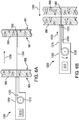
- Figures 5A and 5B illustrate a surgical micro implant or fastener 900.
- Figure 5B is a cross-sectional view of the surgical implant 900 with a cross-sectional plane extending along and including the longitudinal axis of the fastener 900 of Figure 5A .
- the fastener 900 includes many feature of the other example fasteners described herein. Further, the fastener includes a filament/suture 950 extending proximally from a proximal end of the fastener body 905.
- the depth to which the fastener 900 is driven is limited by the amount of slack in the suture 950. This may be accomplished by fixing a proximal end and/or other proximal portion of the suture 950 to a structure, e.g., a fixed position within the driver device, with a predetermined length and/or slack between the fixing location and the fastener body 905.
- the suture 950 may extend longitudinally into an interior location of the fastener head 905.
- An example manufacturing method may include molding, coextruding, or otherwise forming the fastener head 905 over the suture 950. Coextrusion may be particularly advantageous. It should be appreciated however, that any appropriate manufacturing method may be employed.
- a suture 950 of non-stretchable material is provided, it should be understood that other materials, e.g., stretchable materials, may be provided. However, it may be preferable that, even if stretchable, the material have a predeterminable extension limit for particular driving momentums and/or applications.
- a braided, non-braided, mono-filament, and/or multi-filament material may be provided.
- fastener 900 includes micro filaments to anchor into a tissue and resist proximal dislocation after implantation, it should be understood that any other anchoring mechanism, e.g., wings or split portions as described above, may be provided. Moreover, any of the features disclosed with regard to the other example fasteners disclosed herein may be provided in conjunction with the fastener 900.
- FIGS 6A to 6C schematically and sequentially illustrate the bringing into apposition of two tissues using a surgical implant 1300, which shares many features in common with the other implants described herein.
- Implant 1300 has a distal anchoring portion with micro filaments and a proximal threaded portion configured to mate with an internally threaded head 1325, analogous to the implant 200 described above.
- Implant 1300 also includes a proximally extending filament/suture 1350, analogous to the implant 900 described above.
- a surgical system 1200 includes a handpiece 1202 configured to drive the fastener 1300 to a predetermined depth.
- the depth is limited, e.g., by a predetermined amount of slack in the suture 1350.
- the proximal end of the suture 1350 is attached to a capstan 1205 configured to adjust the length of the suture 1350 extending from capstan 1205.
- the capstan 1205 which may be actuated by a motor system or any other appropriate mechanism, may set the slack by reeling off a predetermined length of suture 1350 prior to driving the fastener 1300 and/or the capstan 1205 may have a predetermined amount of allowed rotation such that driving of the fastener 1300 causes the capstan 1205 to rotate only the predetermined amount, thereby setting the driving depth of the fastener 1300.
- the determination of the depth and/or the driving velocity of the fastener 1300 may be determined in a processor 1210 of the handpiece 1202.
- the processing takes place in a processor 1210 located in the handpiece 1202, it should be understood that the processor may be disposed in other parts of the device, e.g., in the shaft 1215 and/or the processing may take place at a location separate from the handpiece 1202 and shaft 1215, e.g., at a remote computing unit that communications, e.g., wirelessly, with the surgical device. Further, it should be understood that the capstan 1210 may be disposed in the shaft 1215.
- the system 1200 determines the location of the first layer of tissue 980 and the second layer of tissue 990. Depending on the application, it may be sufficient for the system 1200 to determine just the respective locations of the tissues 980 and 990.
- the location may be an approximate location of the center of the tissue or a face, e.g., a proximal face, of each tissue.
- the system determines, e.g., via the imaging device and/or the processor 1210, the respective positions of a first or proximal face 981 of the first tissue 980, a second or distal face 982 of the first tissue 980, a first or proximal face 991 of the second tissue 990, and a second or distal face 992 of the second tissue 990 taken along the line or approximately along the line that the fastener 1300 is to be driven. Based on these positional values, the processor 1210 may determine the thickness of each tissue 980, 990 and the space between the distal face 982 of the first tissue 980 and the proximal face 991 of the second tissue, in addition to the location of each of the distal and proximal faces.
- the system 1200 calculates a precise distance and velocity to drive the fastener.
- the system 1200 may also take into account the features of the particular fastener being driven (e.g., dimensions, mass, and/or coefficient of friction) and/or the hardness and/or density of the tissue, which may be approximated, e.g., where the tissue is of a known or expected density and/or hardness, or determined based on the imaging data, e.g., fluoroscopy data.
- the velocity and/or distance may optionally be facilitated by incorporating empirical data into the algorithm or purely based.
- the depth is controlled, e.g., by precisely controlling the length of suture 1350 via the capstan 1215.
- the velocity is precisely controlled, e.g., by a hydraulic driver, e.g., a saline driver.
- position of the first or proximal face 981 of the tissue 980 may be determined without using imaging.
- the system 1200 drives the fastener 1300 in the proximal direction indicated by arrow 1250 through the first tissue 980 across any gap between the first and second tissues 980 and 990, and into the second tissue 990, where the fastener 1300 anchors against distal retraction from the second tissue 990.
- the capstan 1210 is then actuated, e.g., by a motor system controlled by, e.g., processor 1210, to proximally reel the suture 1350, thereby drawing the fastener 1300, along with the tissue 990 to which it is anchored, proximally toward the shaft 1215 and the first tissue 980 adjacent the shaft 1215.
- the proximal direction of movement is indicated by arrow 1260 in Figure 6B .
- the first tissue 980 is restrained from proximal movement by, e.g., contact with the distal end of the shaft 1215.
- the proximal head, or threaded nut, 1325 is moved distally, e.g., by a rotatable driver.
- the distal direction of movement is illustrated by arrow 1250 in Figure 6B .
- the proximal head 1325 may be moved distally at any point after the anchoring fastener 1300 is driven from the shaft 1215. Once the fastener is pulled a sufficient proximal distance, the threaded proximal portion of the body of the fastener 1300 protrudes through the proximal face 981 of the first tissue 980.
- the proximal head 1325 is then coupled to the threaded portion to form a threaded connection.
- a rotatable driver then rotates the head 1325 to distally drive the head 1325 to its implanted position, illustrated in Figure 6C . It should be understood than any final portion of the gap between the distal face 982 of the first tissue and the proximal face 991 of the second tissue 990 may be taken up by continuing to reel in the suture 1350 and/or driving the proximal head 1325 in the distal direction along the threads of the body of the fastener 1300.
- the suture 1350 may be separated from the fastener 1300, e.g., by cutting.
- the system 1200 may include a cutter or other trimming device, e.g., at the distal end of the shaft 1215, in order to cut the suture 1350.
- the system 1200 may provide for trimming some or all of the excess.
- the system may include a cutter or other trimming device, e.g., at the distal end of the shaft 1215, which may be the same or different than the cutter for the suture 1350, in order to remove some or all of the excess.
- tissue 980 and 990 are illustrated in Figures 6A to 6C , it should be understood that the fastener may be driven through any desired number of tissue layers before reaching its anchored position. Moreover, any other example fasteners described herein may be formed with a suture and used in analogous manner to the fastener 1300.
- the system 1200 may hydraulically drive the implant 1300 or use any other appropriate driving mechanism.
- hydraulic delivery it is noted that a very precise force may be delivered at the distal end portion of the shaft 1215 to drive the fastener 1300.
- This force may be controlled by the processor 1210 in connection with hydraulics, e.g., in the handpiece.
- the hydraulic fluid e.g., saline
- the handpiece 1202 may then transmit a very precise force, via the hydraulic fluid extending along the shaft 1215, to the distal end portion of the shaft 1215 to precisely drive the fastener 1300.
- FIG 7 is an illustration of a surgical implant 1000.
- the fastener 1000 includes many feature of the other example fasteners described herein. Further, the fastener 1000 includes a proximal portion having a ratcheting mechanism including a micro ratcheting head 1025 and ratchet teeth 1030.
- the ratcheting mechanism of the implant 1000 performs a function analogous to that of the micro threaded arrangement of the fastener 200 described above. However, as opposed to rotation of the head 225 about the threads 230 of the fastener 200, the ratcheting head 1025 slides, e.g., linearly, along the fastener body 1005.
- the fastener body 1005 may have any appropriate number of ratcheting teeth 1030, including a single ratcheting tooth 1030, arranged to engage the ratcheting head 1025. Further, a single tooth 1030 may extend continuously around the entire radial periphery of the fastener body 1005.
- fastener 1000 includes micro filaments to anchor into a tissue and resist proximal dislocation after implantation, it should be understood that any other anchoring mechanism, e.g., wings or split portions as described above, may be provided. Moreover, any of the features disclosed with regard to the other example fasteners disclosed herein may be provided in conjunction with the fastener 1000.
- FIG 8 is an illustration of a distal end portion of a surgical implant 1100.
- This distal arrangement may be provided on the distal end of any example fastener disclosed herein.
- the distal arrangement includes three concave surfaces 1105 that distally converge to form a sharp point 1110. Separating the three concave surfaces 1105 are three tapered cutting edges 1115. These tapered cutting edges 1115 may facilitate penetration of tissue, e.g., soft tissue.
- the end portion illustrated in Figure 8 includes three concave surfaces 1105 and separated by three corresponding tapered cutting edges 1115, it should be understood that any appropriated number of concave surfaces 1105 and corresponding cutting edges 1115 may be provided.
- tissue repair system that allows great flexibility. For example, smaller defects may be repairable with a single fastener (e.g., fastener 100 or any other fastener described herein), and larger defects may be repairable with a plurality of fasteners, with or without a washer or plate 2200, as described above. Larger defects, e.g., hernias or large holes, may be more suited for a mesh 1300 application, as described above.
- the various implants described herein e.g., fasteners or anchors 100, 200, 300, 500, and 700 and/or nuts 225, may be formed by molding, e.g., injection molding.
- any of the implantable elements described herein may be formed wholly or partly of a material absorbable into the patient's body, or of a non-absorbable material, depending on, e.g., the specific application.
- these elements may be formed of polyglycolic acid (PGA), or a PGA copolymer.
- PGA polyglycolic acid
- these elements may also, or alternatively, be formed of copolymers of polyester and/or nylon and/or other polymer(s).
- these elements may contain one or more shape-memory alloys, e.g., nitinol and/or spring-loaded steel.
- Absorbable materials may be advantageous where there is a potential for misfiring or improper locating of the various implants.
- the fastener e.g., fastener 100, even where not needed, would relatively harmless, as it would eventually absorb into the patient's body.
Claims (15)
- Chirurgische Einrichtung (250), umfassend:- einen länglichen Befestigungskörper (251), der ein proximales Ende und eine distale Spitze und eine Achse aufweist, die sich zwischen dem proximalen Ende und der distalen Spitze erstreckt; wobei der Befestigungskörper (251) äußere Wellen aufweist; und- Flügel (257, 258), die an einem distalen Abschnitt des Befestigungskörpers (251) angeordnet sind; wobei die Flügel (257, 258) äußere Wellen aufweisen;dadurch gekennzeichnet, dass:- die äußeren Wellen des Befestigungskörpers (251) Rippen (255) beinhalten, die parallel zu der Achse entlang der Länge des Befestigungskörpers (251) angeordnet sind;- jeder der Flügel (257, 258) durch einen jeweiligen Schnitt (259), der sich distal und radial nach innen zu dem Befestigungskörper (251) erstreckt, ausgebildet ist;- jeder der Flügel (257, 258) integral mit dem Befestigungskörper (251) ausgebildet ist;- die äußeren Wellen der Flügel (257, 258) sich von dem Befestigungskörper (251) kontinuierlich von den äußeren Wellen des Befestigungskörpers (251) erstrecken und Rippen beinhalten, die sich in einer proximalen Richtung zu einem freien Ende der Flügel erstrecken.
- Chirurgische Einrichtung nach Anspruch 1, gekennzeichnet durch ferner umfassen eines proximalen Kopfs, der an einem proximalen Abschnitt des Befestigungskörpers (251) angeordnet ist, wobei der proximale Kopf sich radial nach außen von dem Befestigungskörper (251) erstreckt, der proximalen Kopf dazu ausgestaltet ist, die Tiefe, zu welcher die Befestigung proximal in eine Schicht oder mehrere Schichten aus Gewebe eingetrieben wird, zu beschränken.
- Chirurgische Einrichtung nach Anspruch 2, dadurch gekennzeichnet, dass der proximale Kopf an dem Befestigungskörper (251) fixiert ist.
- Chirurgische Einrichtung nach Anspruch 2, dadurch gekennzeichnet, dass der proximale Kopf und der Befestigungskörper (251) zusammen als ein einzelnes monolithisches Stück ausgebildet sind.
- Chirurgische Einrichtung nach Anspruch 1, gekennzeichnet durch ferner umfassen eines proximalen Kopfs, der dazu ausgestaltet ist, mit einem proximalen Abschnitt des Befestigungskörpers (251) in Eingriff zu kommen.
- Chirurgische Einrichtung nach Anspruch 5, dadurch gekennzeichnet, dass der proximale Kopf Gewinde beinhaltet, die mit entsprechenden Gewinden an dem proximalen Abschnitt des Befestigungskörpers (251) in Eingriff kommen, wenn der proximale Kopf mit dem proximalen Abschnitt des Befestigungskörpers (251) in Eingriff kommt, wobei eine Drehung des proximalen Kopfs bezüglich der Gewinde des proximalen Abschnitts des Befestigungskörpers (251) eine Bewegung des proximalen Kopfs entlang der Längsachse des Befestigungskörpers (251) verursacht.
- Chirurgische Einrichtung nach Anspruch 5, dadurch gekennzeichnet, dass der proximale Kopf und der Befestigungskörper zusammen eine Ratsche ausbilden, wenn der proximale Kopf mit dem proximalen Abschnitt des Befestigungskörpers in Eingriff kommt, und dadurch, dass der proximale Kopf distal entlang des Befestigungskörpers bewegbar ist und an einer proximalen Bewegung entlang des Befestigungskörpers gehindert wird.
- Chirurgische Einrichtung nach Anspruch 1, dadurch gekennzeichnet, dass die Befestigung aus ein bioabsorbierbares Material umfasst.
- Chirurgische Einrichtung nach Anspruch 8, dadurch gekennzeichnet, dass die gesamte Befestigung bioabsorbierbar ist.
- Chirurgische Einrichtung nach Anspruch 1, dadurch gekennzeichnet, dass die distale Spitze aus einer Gruppe gewählt ist, die aus einer stumpfen Spitze, einer distalen Spitze, die verjüngt ist, einer distalen Spitze, die zu einem scharfen Punkt verjüngt ist, einer Schneidspitze, einer Spitze, die mindestens eine konkav verjüngte Schneidkante beinhaltet, einer Spitze, die drei konkav verjüngte Schneidkanten beinhaltet, und einer umgekehrten Schneidspitze beinhaltet.
- Chirurgische Einrichtung nach Anspruch 1, dadurch gekennzeichnet, dass die distale Spitze drei konkav verjüngte Schneidkanten (1115) beinhaltet, und dadurch, dass die drei konkav verjüngten Schneidkanten (1115) voneinander äquidistant um einen Umfang der Befestigung sind.
- Chirurgische Einrichtung nach Anspruch 1, dadurch gekennzeichnet, dass Rippen (255) des Befestigungskörpers (251) sich radial entlang der gesamten Länge des Befestigungskörpers (251) erstreckt.
- Chirurgische Einrichtung nach Anspruch 1, dadurch gekennzeichnet, dass die Rippen der Flügel (257, 258) sich axialen entlang der gesamten Länge der Flügel (257, 258) erstrecken.
- Chirurgische Einrichtung nach Anspruch 1, dadurch gekennzeichnet, dass die freien Enden der Flügel (257, 258) mindestens einen Vorsprung entlang einer gekrümmten Oberfläche beinhalten, wobei die Rippen der Flügel (257, 258) den mindestens einen Vorsprung ausbilden.
- Chirurgische Einrichtung nach Anspruch 1, dadurch gekennzeichnet, dass mindestens einer der Flügel (257, 258) axial von mindestens einem der anderen Flügel (257, 258) versetzt ist.
Priority Applications (1)
| Application Number | Priority Date | Filing Date | Title |
|---|---|---|---|
| EP17191633.1A EP3278742A2 (de) | 2010-01-20 | 2011-01-20 | Gewebereparaturimplantat sowie einführungsvorrichtung |
Applications Claiming Priority (2)
| Application Number | Priority Date | Filing Date | Title |
|---|---|---|---|
| US29686810P | 2010-01-20 | 2010-01-20 | |
| PCT/US2011/021946 WO2011091184A1 (en) | 2010-01-20 | 2011-01-20 | Tissue repair implant and delivery device and method |
Related Child Applications (1)
| Application Number | Title | Priority Date | Filing Date |
|---|---|---|---|
| EP17191633.1A Division EP3278742A2 (de) | 2010-01-20 | 2011-01-20 | Gewebereparaturimplantat sowie einführungsvorrichtung |
Publications (3)
| Publication Number | Publication Date |
|---|---|
| EP2525723A1 EP2525723A1 (de) | 2012-11-28 |
| EP2525723A4 EP2525723A4 (de) | 2013-07-17 |
| EP2525723B1 true EP2525723B1 (de) | 2017-09-20 |
Family
ID=44278090
Family Applications (5)
| Application Number | Title | Priority Date | Filing Date |
|---|---|---|---|
| EP11735207.0A Withdrawn EP2525722A4 (de) | 2010-01-20 | 2011-01-20 | Gewebereparaturimplantat sowie vorrichtung und verfahren zu seiner verabreichung |
| EP11735202.1A Not-in-force EP2525723B1 (de) | 2010-01-20 | 2011-01-20 | Gewebereparaturimplantat sowie vorrichtung zu seiner verabreichung |
| EP11735204.7A Withdrawn EP2525725A4 (de) | 2010-01-20 | 2011-01-20 | Gewebereparaturimplantat sowie vorrichtung und verfahren zu seiner verabreichung |
| EP11735203.9A Withdrawn EP2525721A4 (de) | 2010-01-20 | 2011-01-20 | Gewebeverschlussvorrichtung und -verfahren |
| EP17191633.1A Withdrawn EP3278742A2 (de) | 2010-01-20 | 2011-01-20 | Gewebereparaturimplantat sowie einführungsvorrichtung |
Family Applications Before (1)
| Application Number | Title | Priority Date | Filing Date |
|---|---|---|---|
| EP11735207.0A Withdrawn EP2525722A4 (de) | 2010-01-20 | 2011-01-20 | Gewebereparaturimplantat sowie vorrichtung und verfahren zu seiner verabreichung |
Family Applications After (3)
| Application Number | Title | Priority Date | Filing Date |
|---|---|---|---|
| EP11735204.7A Withdrawn EP2525725A4 (de) | 2010-01-20 | 2011-01-20 | Gewebereparaturimplantat sowie vorrichtung und verfahren zu seiner verabreichung |
| EP11735203.9A Withdrawn EP2525721A4 (de) | 2010-01-20 | 2011-01-20 | Gewebeverschlussvorrichtung und -verfahren |
| EP17191633.1A Withdrawn EP3278742A2 (de) | 2010-01-20 | 2011-01-20 | Gewebereparaturimplantat sowie einführungsvorrichtung |
Country Status (5)
| Country | Link |
|---|---|
| US (6) | US9050065B2 (de) |
| EP (5) | EP2525722A4 (de) |
| JP (7) | JP5981349B2 (de) |
| CA (4) | CA2825265A1 (de) |
| WO (4) | WO2011091184A1 (de) |
Families Citing this family (59)
| Publication number | Priority date | Publication date | Assignee | Title |
|---|---|---|---|---|
| EP2015681B1 (de) | 2006-05-03 | 2018-03-28 | Datascope Corp. | Gewebeverschlussvorrichtung |
| US7846123B2 (en) | 2007-04-24 | 2010-12-07 | Emory University | Conduit device and system for implanting a conduit device in a tissue wall |
| US10058314B2 (en) | 2010-01-20 | 2018-08-28 | Micro Interventional Devices, Inc. | Tissue closure device and method |
| JP5981349B2 (ja) * | 2010-01-20 | 2016-08-31 | マイクロ インターベンショナル デバイシズ,インコーポレイティド | 組織修復用インプラント及び投入デバイス及び方法 |
| US10743854B2 (en) | 2010-01-20 | 2020-08-18 | Micro Interventional Devices, Inc. | Tissue closure device and method |
| US9980708B2 (en) | 2010-01-20 | 2018-05-29 | Micro Interventional Devices, Inc. | Tissue closure device and method |
| US10959840B2 (en) | 2010-01-20 | 2021-03-30 | Micro Interventional Devices, Inc. | Systems and methods for affixing a prosthesis to tissue |
| US9050066B2 (en) * | 2010-06-07 | 2015-06-09 | Kardium Inc. | Closing openings in anatomical tissue |
| US9492952B2 (en) | 2010-08-30 | 2016-11-15 | Endo-Surgery, Inc. | Super-hydrophilic structures |
| EP2667792B1 (de) | 2011-01-28 | 2020-05-06 | Apica Cardiovascular Limited | Systeme zum abdichten einer gewebewandpunktion |
| CA2826413A1 (en) | 2011-02-01 | 2012-08-09 | Georgia Tech Research Corporation | Systems for implanting and using a conduit within a tissue wall |
| US20140039549A1 (en) | 2011-04-21 | 2014-02-06 | Novogate Medical Ltd | Tissue closure device and method of deliver and uses thereof |
| EP3395298A1 (de) | 2011-06-27 | 2018-10-31 | University of Maryland, Baltimore | Transapikale mitralklappenreparaturvorrichtung |
| US8535339B2 (en) | 2011-12-18 | 2013-09-17 | Via Surgical Ltd. | Apparatus and method for suturing |
| RU2635453C2 (ru) * | 2011-12-29 | 2017-11-13 | Этикон, Инк. | Адгезивная структура с прокалывающими ткань выступами на поверхности |
| US9888913B2 (en) | 2012-05-31 | 2018-02-13 | Via Surgical Ltd. | Variable depth surgical fixation |
| US9198704B2 (en) | 2012-07-18 | 2015-12-01 | Jmea Corporation | Impact and drive system for prosthesis deployment device |
| US10052097B2 (en) | 2012-07-26 | 2018-08-21 | Nyxoah SA | Implant unit delivery tool |
| WO2014189540A1 (en) * | 2012-10-16 | 2014-11-27 | Catalano Peter J | Method and apparatus for treating obstructive sleep apnea (osa) |
| US20150289860A1 (en) * | 2012-11-03 | 2015-10-15 | Novogate Medical Ltd. | Intercostal delivery system and methods thereof |
| WO2014117087A1 (en) | 2013-01-25 | 2014-07-31 | Apica Cardiovascular Limited | Systems and methods for percutaneous access, stabilization and closure of organs |
| ES2684316T3 (es) | 2013-03-11 | 2018-10-02 | Via Surgical Ltd. | Indicador de calidad con hilvanador quirúrgico |
| US9474530B2 (en) | 2013-03-14 | 2016-10-25 | C.R. Bard, Inc. | Handling of fasteners within a surgical instrument |
| US9427230B2 (en) | 2013-03-14 | 2016-08-30 | C.R. Bard, Inc. | Handling of fasteners within a surgical instrument |
| EP2967532B1 (de) * | 2013-03-15 | 2021-11-03 | Micro Interventional Devices, Inc. | Gewebeverschlussvorrichtung |
| EP2968717A4 (de) | 2013-03-15 | 2017-02-22 | Apk Advanced Medical Technologies, Inc. | Vorrichtungen, systeme und verfahren zur implantation und verwendung eines steckers in einer gewebewand |
| US9724082B2 (en) * | 2013-03-15 | 2017-08-08 | Cook Medical Technologies Llc | Delivery system for tissue opening closures |
| US9610069B2 (en) * | 2013-04-26 | 2017-04-04 | Medtronic-Xomed, Inc. | Tissue stabilization and repair device |
| US9463019B2 (en) | 2013-05-16 | 2016-10-11 | University Of Louisville Research Foundation, Inc. | Trocar site closure assembly |
| US9155899B2 (en) * | 2013-06-17 | 2015-10-13 | Nyxoah SA | Antenna buffer layer for an electromagnetic control unit |
| KR101490613B1 (ko) | 2013-08-06 | 2015-02-11 | 박용호 | 가슴 및 엉덩이 리프팅 시술용 제품 및 그 시술법 |
| JP6485817B2 (ja) * | 2013-08-21 | 2019-03-20 | ヤンセン バイオファーマ インク. | 抗ウイルス化合物 |
| US9301746B2 (en) | 2013-10-11 | 2016-04-05 | Abbott Cardiovascular Systems, Inc. | Suture-based closure with hemostatic tract plug |
| WO2015077356A1 (en) | 2013-11-19 | 2015-05-28 | Wheeler William K | Fastener applicator with interlock |
| US9681864B1 (en) | 2014-01-03 | 2017-06-20 | Harpoon Medical, Inc. | Method and apparatus for transapical procedures on a mitral valve |
| CA2952077A1 (en) * | 2014-06-10 | 2015-12-17 | Micro Interventional Devices, Inc. | Tissue closure device and method |
| EP3212250A4 (de) | 2014-10-31 | 2018-07-11 | Thoratec Corporation | Apikale verbinder und instrumente zur verwendung in einer herzwand |
| WO2016170423A1 (en) | 2015-04-23 | 2016-10-27 | Via Surgical Ltd. | Surgical fastener delivery and locking mechanism |
| EP3753498B1 (de) | 2015-10-02 | 2023-12-06 | Harpoon Medical, Inc. | Distale ankervorrichtung zur mitralklappenreparatur |
| US10463492B2 (en) | 2015-11-17 | 2019-11-05 | Edwards Lifesciences Corporation | Systems and devices for setting an anchor |
| CN108601652A (zh) * | 2015-12-07 | 2018-09-28 | 微介入设备公司 | 将假体固定至组织 |
| GB2546488B (en) | 2016-01-19 | 2020-05-13 | Ford Global Tech Llc | An engine exhaust gas recirculation system with at least one exhaust recirculation treatment device |
| JP2017140109A (ja) * | 2016-02-08 | 2017-08-17 | テルモ株式会社 | 治療方法および医療用装置 |
| CN105852919B (zh) * | 2016-04-22 | 2019-05-10 | 广东脉搏医疗科技有限公司 | 一种组织封闭器械 |
| CN110418613A (zh) * | 2017-03-16 | 2019-11-05 | 坎努弗洛公司 | 用于将片状材料固定到目标组织的系统和方法 |
| KR101891435B1 (ko) * | 2017-04-05 | 2018-08-23 | 울산대학교 산학협력단 | 복강경용 지혈거즈 운반장치 |
| US10765515B2 (en) | 2017-04-06 | 2020-09-08 | University Of Maryland, Baltimore | Distal anchor apparatus and methods for mitral valve repair |
| EP3630014A4 (de) | 2017-05-26 | 2021-11-03 | The Johns Hopkins University | Systeme und verfahren zur behandlung von herzklappenfehlern |
| WO2018236892A1 (en) * | 2017-06-19 | 2018-12-27 | The Feinstein Institute For Medical Research | HERNIA REPAIR DEVICE |
| EP3641699B1 (de) * | 2017-06-19 | 2023-08-30 | Harpoon Medical, Inc. | Vorrichtung für herzoperationen |
| EP3700434A1 (de) | 2017-10-24 | 2020-09-02 | University of Maryland, Baltimore | Verfahren und vorrichtung für herzeingriffe |
| US11135062B2 (en) | 2017-11-20 | 2021-10-05 | Valtech Cardio Ltd. | Cinching of dilated heart muscle |
| RU2699171C1 (ru) * | 2017-12-22 | 2019-09-03 | Сергей Альвинович Колыванов | Многоразовый инструмент для наложения кожных швов с вертикальной катушкой |
| US11653928B2 (en) | 2018-03-28 | 2023-05-23 | Datascope Corp. | Device for atrial appendage exclusion |
| CN112105304A (zh) * | 2018-03-29 | 2020-12-18 | 波士顿科学医学有限公司 | 带有固定构件的闭塞医疗器械 |
| US11517435B2 (en) | 2018-05-04 | 2022-12-06 | Edwards Lifesciences Corporation | Ring-based prosthetic cardiac valve |
| EP3883483A1 (de) | 2019-03-25 | 2021-09-29 | Laminar, Inc. | Vorrichtungen und systeme zur behandlung des linken herzohrs |
| KR102281425B1 (ko) * | 2019-12-19 | 2021-07-27 | 주식회사 포스코 | 가공성이 우수한 초고강도 냉연강판용 조질압연 롤, 조질압연 롤의 제조방법 및 가공성이 우수한 초고강도 냉연강판의 제조방법 |
| US20230158281A1 (en) * | 2020-04-10 | 2023-05-25 | The Regents Of The University Of California | Systems, devices, and methods for delivering a substance within a target tissue |
Citations (1)
| Publication number | Priority date | Publication date | Assignee | Title |
|---|---|---|---|---|
| US20030097148A1 (en) * | 2001-11-20 | 2003-05-22 | Tero Valimaa | Tissue fastener |
Family Cites Families (167)
| Publication number | Priority date | Publication date | Assignee | Title |
|---|---|---|---|---|
| US3897035A (en) | 1974-03-25 | 1975-07-29 | Knock N Lok International | Wall fastener |
| US3959960A (en) * | 1975-03-12 | 1976-06-01 | Santos Manuel V | Tensioning, twisting and cutting device for sutures |
| SU715082A1 (ru) | 1977-01-24 | 1980-02-15 | Всесоюзный научно-исследовательский и испытательный институт медицинской техники | Хирургический сшивающий аппарат |
| US4741330A (en) | 1983-05-19 | 1988-05-03 | Hayhurst John O | Method and apparatus for anchoring and manipulating cartilage |
| US5601557A (en) * | 1982-05-20 | 1997-02-11 | Hayhurst; John O. | Anchoring and manipulating tissue |
| US4488523A (en) * | 1982-09-24 | 1984-12-18 | United States Surgical Corporation | Flexible, hydraulically actuated device for applying surgical fasteners |
| US4873976A (en) * | 1984-02-28 | 1989-10-17 | Schreiber Saul N | Surgical fasteners and method |
| US4669473A (en) * | 1985-09-06 | 1987-06-02 | Acufex Microsurgical, Inc. | Surgical fastener |
| US4884572A (en) * | 1986-05-20 | 1989-12-05 | Concept, Inc. | Tack and applicator for treating torn bodily material in vivo |
| US5478353A (en) | 1987-05-14 | 1995-12-26 | Yoon; Inbae | Suture tie device system and method for suturing anatomical tissue proximate an opening |
| US4968315A (en) | 1987-12-15 | 1990-11-06 | Mitek Surgical Products, Inc. | Suture anchor and suture anchor installation tool |
| US4938760A (en) * | 1989-03-29 | 1990-07-03 | American Medical Systems, Inc. | Female suspension procedure |
| US5059206A (en) | 1989-04-12 | 1991-10-22 | Winters Thomas F | Method and apparatus for repairing a tear in a knee meniscus |
| US4978265A (en) * | 1989-06-28 | 1990-12-18 | Wan Thomas E De | Sleeve anchor for screw |
| US5127412A (en) * | 1990-03-14 | 1992-07-07 | Cosmetto Aristodeme J | Skin tensioning |
| US5372146A (en) * | 1990-11-06 | 1994-12-13 | Branch; Thomas P. | Method and apparatus for re-approximating tissue |
| FI95537C (fi) * | 1992-01-24 | 1996-02-26 | Biocon Oy | Kirurginen implantti |
| FI90622C (fi) | 1992-01-24 | 1994-03-10 | Biocon Oy | Kirurginen asennusinstrumentti |
| US5417699A (en) * | 1992-12-10 | 1995-05-23 | Perclose Incorporated | Device and method for the percutaneous suturing of a vascular puncture site |
| US5356424A (en) | 1993-02-05 | 1994-10-18 | American Cyanamid Co. | Laparoscopic suturing device |
| US5342376A (en) * | 1993-05-03 | 1994-08-30 | Dermagraphics, Inc. | Inserting device for a barbed tissue connector |
| US5505735A (en) | 1993-06-10 | 1996-04-09 | Mitek Surgical Products, Inc. | Surgical anchor and method for using the same |
| US5584859A (en) * | 1993-10-12 | 1996-12-17 | Brotz; Gregory R. | Suture assembly |
| US5694782A (en) | 1995-06-06 | 1997-12-09 | Alsenz; Richard H. | Reverse flow defrost apparatus and method |
| US5792142A (en) | 1996-02-16 | 1998-08-11 | Howmedica, Inc. | Cutting tip |
| US5782844A (en) * | 1996-03-05 | 1998-07-21 | Inbae Yoon | Suture spring device applicator |
| US5976139A (en) * | 1996-07-17 | 1999-11-02 | Bramlet; Dale G. | Surgical fastener assembly |
| US6117162A (en) | 1996-08-05 | 2000-09-12 | Arthrex, Inc. | Corkscrew suture anchor |
| US6565581B1 (en) * | 1996-09-16 | 2003-05-20 | Origin Medsystems, Inc. | Apparatus and method for performing an anastomosis |
| US5782864A (en) * | 1997-04-03 | 1998-07-21 | Mitek Surgical Products, Inc. | Knotless suture system and method |
| US5814051A (en) | 1997-06-06 | 1998-09-29 | Mitex Surgical Products, Inc. | Suture anchor insertion system |
| US6071292A (en) * | 1997-06-28 | 2000-06-06 | Transvascular, Inc. | Transluminal methods and devices for closing, forming attachments to, and/or forming anastomotic junctions in, luminal anatomical structures |
| US6692499B2 (en) | 1997-07-02 | 2004-02-17 | Linvatec Biomaterials Oy | Surgical fastener for tissue treatment |
| US6159234A (en) * | 1997-08-01 | 2000-12-12 | Peter M. Bonutti | Method and apparatus for securing a suture |
| US6010525A (en) * | 1997-08-01 | 2000-01-04 | Peter M. Bonutti | Method and apparatus for securing a suture |
| US5964782A (en) * | 1997-09-18 | 1999-10-12 | Scimed Life Systems, Inc. | Closure device and method |
| US6027523A (en) | 1997-10-06 | 2000-02-22 | Arthrex, Inc. | Suture anchor with attached disk |
| US6056778A (en) * | 1997-10-29 | 2000-05-02 | Arthrex, Inc. | Meniscal repair device |
| US5976127A (en) | 1998-01-14 | 1999-11-02 | Lax; Ronald | Soft tissue fixation devices |
| DE19801219A1 (de) * | 1998-01-15 | 1999-07-22 | Holger K Dr Essiger | Knochennagel |
| DE19806693A1 (de) * | 1998-02-18 | 1999-08-19 | Daum Gmbh | Tumortherapie |
| JP3799810B2 (ja) * | 1998-03-30 | 2006-07-19 | ニプロ株式会社 | 経カテーテル手術用閉鎖栓およびカテーテル組立体 |
| EP1067873A1 (de) * | 1998-04-01 | 2001-01-17 | Bionx Implants Oy | Bioresorbierbares befestigungselement zur chirurgischen behandlung von gewebe |
| US5993475A (en) * | 1998-04-22 | 1999-11-30 | Bristol-Myers Squibb Co. | Tissue repair device |
| US6030410A (en) * | 1998-05-18 | 2000-02-29 | Zurbruegg; Heinz Robert | Sternal closure technique and kit for performing same |
| EP1079740B1 (de) | 1998-05-21 | 2007-08-29 | Christopher J. Walshe | System zum fixieren von gewebe |
| US6174323B1 (en) * | 1998-06-05 | 2001-01-16 | Broncus Technologies, Inc. | Method and assembly for lung volume reduction |
| US7569062B1 (en) | 1998-07-15 | 2009-08-04 | St. Jude Medical, Inc. | Mitral and tricuspid valve repair |
| US6669707B1 (en) * | 1998-07-21 | 2003-12-30 | Lee L. Swanstrom | Method and apparatus for attaching or locking an implant to an anatomic vessel or hollow organ wall |
| US6387113B1 (en) * | 1999-02-02 | 2002-05-14 | Biomet, Inc. | Method and apparatus for repairing a torn meniscus |
| US20050283189A1 (en) | 1999-03-31 | 2005-12-22 | Rosenblatt Peter L | Systems and methods for soft tissue reconstruction |
| US6077277A (en) * | 1999-04-05 | 2000-06-20 | Starion Instruments, Inc. | Suture welding device |
| CA2620783C (en) * | 1999-04-09 | 2011-04-05 | Evalve, Inc. | Methods and apparatus for cardiac valve repair |
| US20050222665A1 (en) | 1999-04-23 | 2005-10-06 | Ernest Aranyi | Endovascular fastener applicator |
| US7416554B2 (en) * | 2002-12-11 | 2008-08-26 | Usgi Medical Inc | Apparatus and methods for forming and securing gastrointestinal tissue folds |
| US7160312B2 (en) | 1999-06-25 | 2007-01-09 | Usgi Medical, Inc. | Implantable artificial partition and methods of use |
| US7618426B2 (en) | 2002-12-11 | 2009-11-17 | Usgi Medical, Inc. | Apparatus and methods for forming gastrointestinal tissue approximations |
| US6206895B1 (en) * | 1999-07-13 | 2001-03-27 | Scion Cardio-Vascular, Inc. | Suture with toggle and delivery system |
| US6120525A (en) * | 1999-07-14 | 2000-09-19 | Westcott; Mitchell S. | Skin tensioning device |
| US6231561B1 (en) | 1999-09-20 | 2001-05-15 | Appriva Medical, Inc. | Method and apparatus for closing a body lumen |
| US6679895B1 (en) * | 1999-11-05 | 2004-01-20 | Onux Medical, Inc. | Apparatus and method for placing suture wires into tissue for the approximation and tensioning of tissue |
| US7887551B2 (en) * | 1999-12-02 | 2011-02-15 | Smith & Nephew, Inc. | Soft tissue attachment and repair |
| US6331182B1 (en) * | 1999-12-13 | 2001-12-18 | Jonathan Tiefenbrun | Medical twisting device and method for forming a surgical closure |
| US6635073B2 (en) * | 2000-05-03 | 2003-10-21 | Peter M. Bonutti | Method of securing body tissue |
| US6623492B1 (en) * | 2000-01-25 | 2003-09-23 | Smith & Nephew, Inc. | Tissue fastener |
| CA2408069C (en) | 2000-05-10 | 2005-03-29 | Canica Design Inc. | System and method for moving and stretching plastic tissue |
| US7361185B2 (en) * | 2001-05-09 | 2008-04-22 | Canica Design, Inc. | Clinical and surgical system and method for moving and stretching plastic tissue |
| US7172615B2 (en) | 2000-05-19 | 2007-02-06 | Coapt Systems, Inc. | Remotely anchored tissue fixation device |
| US6663633B1 (en) | 2000-10-25 | 2003-12-16 | Pierson, Iii Raymond H. | Helical orthopedic fixation and reduction device, insertion system, and associated methods |
| US6500184B1 (en) | 2001-01-31 | 2002-12-31 | Yung C. Chan | Suturing apparatus and method of suturing |
| US20050125011A1 (en) * | 2001-04-24 | 2005-06-09 | Spence Paul A. | Tissue fastening systems and methods utilizing magnetic guidance |
| US7311731B2 (en) | 2001-04-27 | 2007-12-25 | Richard C. Satterfield | Prevention of myocardial infarction induced ventricular expansion and remodeling |
| US20020169452A1 (en) * | 2001-05-14 | 2002-11-14 | Pertti Tormala | Minimally traumatic surgical device for tissue treatment |
| US7104949B2 (en) | 2001-08-31 | 2006-09-12 | Ams Research Corporation | Surgical articles for placing an implant about a tubular tissue structure and methods |
| US20050267495A1 (en) * | 2004-05-17 | 2005-12-01 | Gateway Medical, Inc. | Systems and methods for closing internal tissue defects |
| WO2003024300A2 (en) * | 2001-09-14 | 2003-03-27 | Onux Medical, Inc. | Surgical suturing instrument and method of use |
| US20050177180A1 (en) * | 2001-11-28 | 2005-08-11 | Aptus Endosystems, Inc. | Devices, systems, and methods for supporting tissue and/or structures within a hollow body organ |
| US7150750B2 (en) * | 2002-01-10 | 2006-12-19 | Boston Scientific Scimed, Inc. | Method and device for endoscopic suturing |
| WO2003059152A2 (en) * | 2002-01-14 | 2003-07-24 | Nmt Medical, Inc. | Patent foramen ovale (pfo) closure method and device |
| AU2003212942A1 (en) | 2002-02-04 | 2003-09-02 | Damage Control Surgical Technologies, Inc. | Method and apparatus for solid organ tissue approximation |
| CA2476731C (en) * | 2002-02-25 | 2007-07-03 | Jeffrey E. Yeung | Expandable fastener with compressive grips |
| EP1482841B1 (de) | 2002-03-14 | 2005-12-07 | Yeung, Jeffery E. | Nahtanker und adaptationsvorrichtung |
| US7850709B2 (en) * | 2002-06-04 | 2010-12-14 | Abbott Vascular Inc. | Blood vessel closure clip and delivery device |
| US20060122633A1 (en) * | 2002-06-13 | 2006-06-08 | John To | Methods and devices for termination |
| US6966916B2 (en) * | 2002-09-26 | 2005-11-22 | Kumar Sarbjeet S | Device and method for surgical repair of abdominal wall hernias |
| US7087064B1 (en) * | 2002-10-15 | 2006-08-08 | Advanced Cardiovascular Systems, Inc. | Apparatuses and methods for heart valve repair |
| US20040138707A1 (en) * | 2003-01-14 | 2004-07-15 | Greenhalgh E. Skott | Anchor removable from a substrate |
| WO2004069055A2 (en) * | 2003-02-04 | 2004-08-19 | Ev3 Sunnyvale Inc. | Patent foramen ovale closure system |
| EP1605865B1 (de) * | 2003-03-17 | 2008-12-10 | ev3 Endovascular, Inc. | Stent mit laminierter dünnfilmverbund |
| WO2005004727A1 (en) | 2003-07-11 | 2005-01-20 | Endogun Medical Systems Ltd. | Surgical fasteners and devices for surgical fastening |
| WO2005009285A2 (en) | 2003-07-21 | 2005-02-03 | The Trustees Of The University Of Pennsylvania | Percutaneous heart valve |
| US8308765B2 (en) * | 2004-05-07 | 2012-11-13 | Usgi Medical, Inc. | Apparatus and methods for positioning and securing anchors |
| US7780701B1 (en) | 2003-08-13 | 2010-08-24 | Biomet Sports Medicine, Llc | Suture anchor |
| US20050075654A1 (en) * | 2003-10-06 | 2005-04-07 | Brian Kelleher | Methods and devices for soft tissue securement |
| EP1699366A4 (de) * | 2003-12-12 | 2011-01-26 | Usgi Medical Inc | Gerät und verfahren zur bildund und fixierung von gastrointestinalen gewebefalten |
| US7166127B2 (en) | 2003-12-23 | 2007-01-23 | Mitralign, Inc. | Tissue fastening systems and methods utilizing magnetic guidance |
| US20050187568A1 (en) * | 2004-02-20 | 2005-08-25 | Klenk Alan R. | Devices and methods for closing a patent foramen ovale with a coil-shaped closure device |
| NL1025830C2 (nl) | 2004-03-26 | 2005-02-22 | Eric Berreklouw | Samenstel omvattende een ring voor bevestiging in een door lichaamsweefsel omgeven doorgang alsmede een applicator voor het in de doorgang plaatsen van de ring. |
| US20050228413A1 (en) * | 2004-04-12 | 2005-10-13 | Binmoeller Kenneth F | Automated transluminal tissue targeting and anchoring devices and methods |
| US8425539B2 (en) | 2004-04-12 | 2013-04-23 | Xlumena, Inc. | Luminal structure anchoring devices and methods |
| US7833238B2 (en) * | 2004-04-19 | 2010-11-16 | Granit Medical Innovations, Llc | Endoscopic anchoring device and associated method |
| US7390329B2 (en) * | 2004-05-07 | 2008-06-24 | Usgi Medical, Inc. | Methods for grasping and cinching tissue anchors |
| US7500972B2 (en) * | 2004-05-07 | 2009-03-10 | Ethicon Endo-Surgery, Inc. | Device for alternately holding, or effecting relative longitudinal movement, of members of a medical instrument |
| US20050256532A1 (en) * | 2004-05-12 | 2005-11-17 | Asha Nayak | Cardiovascular defect patch device and method |
| US7785348B2 (en) * | 2004-05-14 | 2010-08-31 | Ethicon Endo-Surgery, Inc. | Devices and methods of locking and cutting a suture in a medical procedure |
| RU2416371C2 (ru) | 2004-06-02 | 2011-04-20 | КейЭфэкс МЕДИКАЛ КОРПОРЕЙШН | Система и способ крепления мягкой ткани к кости |
| US8361113B2 (en) * | 2006-02-03 | 2013-01-29 | Biomet Sports Medicine, Llc | Method and apparatus for coupling soft tissue to a bone |
| US7905904B2 (en) | 2006-02-03 | 2011-03-15 | Biomet Sports Medicine, Llc | Soft tissue repair device and associated methods |
| US20060190042A1 (en) | 2004-11-05 | 2006-08-24 | Arthrotek, Inc. | Tissue repair assembly |
| US8986345B2 (en) * | 2004-12-07 | 2015-03-24 | Biomet Sports Medicine, Llc | Expanding suture anchor having an actuator pin |
| US8333777B2 (en) * | 2005-04-22 | 2012-12-18 | Benvenue Medical, Inc. | Catheter-based tissue remodeling devices and methods |
| US7632313B2 (en) | 2005-04-29 | 2009-12-15 | Jmea Corporation | Disc repair system |
| US7645286B2 (en) * | 2005-05-20 | 2010-01-12 | Neotract, Inc. | Devices, systems and methods for retracting, lifting, compressing, supporting or repositioning tissues or anatomical structures |
| US20060282088A1 (en) | 2005-06-08 | 2006-12-14 | Ryan Timothy J | Apparatus and methods for delivering sutures |
| WO2007028092A1 (en) * | 2005-09-01 | 2007-03-08 | Cordis Corporation | Patent foramen ovale closure method |
| WO2007035726A2 (en) | 2005-09-19 | 2007-03-29 | Mayo Foundation For Medical Education And Research | Implantable closure apparatus and methods |
| US7875041B2 (en) * | 2005-09-28 | 2011-01-25 | Olympus Medical Systems Corp. | Suturing method for penetrating hole |
| US8123768B2 (en) * | 2005-10-24 | 2012-02-28 | Gil Vardi | Method and system to restrict stomach size |
| US20070112362A1 (en) * | 2005-11-14 | 2007-05-17 | Olympus Medical Systems Corp. | Perforation suturing method |
| US7815659B2 (en) * | 2005-11-15 | 2010-10-19 | Ethicon Endo-Surgery, Inc. | Suture anchor applicator |
| US7632308B2 (en) * | 2005-11-23 | 2009-12-15 | Didier Loulmet | Methods, devices, and kits for treating mitral valve prolapse |
| EP1797828B1 (de) | 2005-12-15 | 2009-06-24 | Arthrex, Inc. | Gewindenahtanker mit Anfangssteigung |
| US7815923B2 (en) | 2005-12-29 | 2010-10-19 | Cook Biotech Incorporated | Implantable graft material |
| WO2007098212A2 (en) | 2006-02-18 | 2007-08-30 | Amir Belson | Endoscopic suturing devices |
| GB0607608D0 (en) | 2006-04-18 | 2006-05-31 | Royal Brompton & Harefield Nhs | Sternal closure device |
| US8556934B2 (en) * | 2006-05-19 | 2013-10-15 | Norman Godin | Article, system, and method for securing medical devices to treat obesity, gastro-esophageal reflux disease (GERD) and irritable bowel syndrome (IBS) reversibly |
| AU2007260914B2 (en) * | 2006-06-21 | 2012-11-29 | Cook Biotech Incorporated | Fistula grafts and related methods and systems useful for treating gastrointestinal fistulae |
| US8202295B2 (en) | 2006-07-20 | 2012-06-19 | Kaplan Lee D | Surgical instruments |
| EP2073686B1 (de) * | 2006-10-10 | 2018-01-10 | Adrian Edward Park | Einstellbare schnur- und netzretraktoren |
| WO2008045635A2 (en) * | 2006-10-12 | 2008-04-17 | The Catheter Exchange, Inc. | Method and device for attaching a patch |
| US8551139B2 (en) | 2006-11-30 | 2013-10-08 | Cook Medical Technologies Llc | Visceral anchors for purse-string closure of perforations |
| US20080161850A1 (en) * | 2006-12-28 | 2008-07-03 | William Bruce Weisenburgh | Suture anchoring system |
| WO2008088982A1 (en) * | 2007-01-16 | 2008-07-24 | Board Of Regents, The University Of Texas System | Needle-electrode and tissue anchor system |
| US8070802B2 (en) | 2007-02-23 | 2011-12-06 | The Trustees Of The University Of Pennsylvania | Mitral valve system |
| US7780702B2 (en) * | 2007-02-27 | 2010-08-24 | Olympus Medical Systems Corp. | Suture tool |
| EP2134409A4 (de) | 2007-03-09 | 2013-07-17 | Anthem Orthopaedics Llc | Implantierbare arzneiabgabevorrichtung und abgabeinstrument und anwendungsverfahren dafür |
| EP2134294B1 (de) | 2007-03-22 | 2016-04-13 | P Tech, LLC | Vorrichtungen zur intrakorporalen verbindung oder verriegelung von implantaten mit wärmeenergie |
| US20080255612A1 (en) * | 2007-04-13 | 2008-10-16 | Angiotech Pharmaceuticals, Inc. | Self-retaining systems for surgical procedures |
| EP2150183B1 (de) * | 2007-05-31 | 2013-03-20 | Cook Medical Technologies LLC | Nahtverschluss |
| US7967842B2 (en) * | 2007-06-01 | 2011-06-28 | Ethicon Endo-Surgery, Inc. | Integrated securement and closure apparatus |
| US8992569B2 (en) | 2007-06-29 | 2015-03-31 | Ethicon Endo-Surgery, Inc. | Insertion device and method of use |
| US20100049289A1 (en) | 2007-07-10 | 2010-02-25 | Ams Research Corporation | Tissue anchor |
| US8551118B2 (en) | 2007-07-18 | 2013-10-08 | Ethicon Endo-Surgery, Inc. | Hybrid endoscopic/laparoscopic method for forming serosa to serosa plications in a gastric cavity |
| US7998150B2 (en) * | 2007-09-28 | 2011-08-16 | Olympus Medical Systems Corp. | Suturing device |
| EP2222232B1 (de) | 2007-10-19 | 2018-12-12 | Ancora Heart, Inc. | Vorrichtungen zum Abschluss und/oder Schneiden von Spannseilen |
| US20090228040A1 (en) * | 2008-03-04 | 2009-09-10 | Medtronic Vascular, Inc. | Mechanism and Method for Closing an Arteriotomy |
| US8696689B2 (en) | 2008-03-18 | 2014-04-15 | Medtronic Ventor Technologies Ltd. | Medical suturing device and method for use thereof |
| US8020741B2 (en) | 2008-03-18 | 2011-09-20 | Barosense, Inc. | Endoscopic stapling devices and methods |
| US8932327B2 (en) | 2008-04-01 | 2015-01-13 | Covidien Lp | Anchoring device |
| CA2721066A1 (en) | 2008-04-08 | 2009-10-15 | Endopro Solutions L.L.C. | Apparatus and method for gastric reduction |
| CN102056552B (zh) | 2008-04-15 | 2013-07-03 | 伊西康有限责任公司 | 具有双向保持器或单向保持器的自保持缝合线 |
| US20090287304A1 (en) * | 2008-05-13 | 2009-11-19 | Kardium Inc. | Medical Device for Constricting Tissue or a Bodily Orifice, for example a mitral valve |
| US9011489B2 (en) | 2008-05-14 | 2015-04-21 | Boston Scientific Scimed, Inc. | Surgical composite barbed suture |
| US20100016885A1 (en) | 2008-07-21 | 2010-01-21 | Eidenschink Tracee E J | Device to close openings in body tissue |
| US9271706B2 (en) | 2008-08-12 | 2016-03-01 | Covidien Lp | Medical device for wound closure and method of use |
| US8262675B2 (en) * | 2008-10-29 | 2012-09-11 | Ethicon Endo-Surgery, Inc. | Methods and devices for applying multiple suture anchors |
| US20100113873A1 (en) * | 2008-11-06 | 2010-05-06 | Takayuki Suzuki | Suturing device and suturing system |
| JP5724134B2 (ja) * | 2008-12-09 | 2015-05-27 | クック・メディカル・テクノロジーズ・リミテッド・ライアビリティ・カンパニーCook Medical Technologies Llc | 後退可能な鋲留め器具 |
| JP4705201B2 (ja) | 2009-03-05 | 2011-06-22 | オリンパスメディカルシステムズ株式会社 | 生検組織採取処置具 |
| EP2413809B1 (de) | 2009-04-03 | 2014-10-08 | Cook Medical Technologies LLC | Medizinische vorrichtungen zur schnellen ablage und fixierung von gewebeankern |
| US8500757B2 (en) | 2009-07-28 | 2013-08-06 | Edwards Lifesciences Corporation | Surgical puncture cinch and closure system |
| EP2289440B1 (de) | 2009-08-27 | 2013-05-29 | Stryker Leibinger GmbH & Co. KG | Knochenanker, orthopädische Vorrichtung und orthopädisches System |
| EP2498685B1 (de) | 2009-11-09 | 2014-06-18 | Entourage Medical Technologies, Inc. | System für gewebezugang und -verschluss |
| JP5981349B2 (ja) | 2010-01-20 | 2016-08-31 | マイクロ インターベンショナル デバイシズ,インコーポレイティド | 組織修復用インプラント及び投入デバイス及び方法 |
| US8894667B2 (en) | 2010-03-09 | 2014-11-25 | University Of Louisville Research Foundation, Inc. | Endoscopic closure device |
| CN103118605B (zh) | 2010-06-26 | 2016-07-27 | 瓦索斯蒂奇股份有限公司 | 用于经心尖进入和闭合的方法和装置 |
| US9237887B2 (en) | 2011-05-19 | 2016-01-19 | Biomet Sports Medicine, Llc | Tissue engaging member |
-
2011
- 2011-01-20 JP JP2012550131A patent/JP5981349B2/ja not_active Expired - Fee Related
- 2011-01-20 WO PCT/US2011/021946 patent/WO2011091184A1/en active Application Filing
- 2011-01-20 EP EP11735207.0A patent/EP2525722A4/de not_active Withdrawn
- 2011-01-20 CA CA2825265A patent/CA2825265A1/en not_active Abandoned
- 2011-01-20 CA CA2825184A patent/CA2825184A1/en not_active Abandoned
- 2011-01-20 EP EP11735202.1A patent/EP2525723B1/de not_active Not-in-force
- 2011-01-20 JP JP2012550129A patent/JP5981348B2/ja not_active Expired - Fee Related
- 2011-01-20 EP EP11735204.7A patent/EP2525725A4/de not_active Withdrawn
- 2011-01-20 JP JP2012550130A patent/JP6073685B2/ja active Active
- 2011-01-20 CA CA2825263A patent/CA2825263A1/en not_active Abandoned
- 2011-01-20 JP JP2012550128A patent/JP5828147B2/ja not_active Expired - Fee Related
- 2011-01-20 US US13/010,766 patent/US9050065B2/en active Active
- 2011-01-20 EP EP11735203.9A patent/EP2525721A4/de not_active Withdrawn
- 2011-01-20 US US13/010,777 patent/US20110178537A1/en not_active Abandoned
- 2011-01-20 US US13/010,769 patent/US8764795B2/en active Active - Reinstated
- 2011-01-20 WO PCT/US2011/021952 patent/WO2011091189A1/en active Application Filing
- 2011-01-20 EP EP17191633.1A patent/EP3278742A2/de not_active Withdrawn
- 2011-01-20 US US13/010,774 patent/US9138211B2/en active Active
- 2011-01-20 CA CA2825186A patent/CA2825186A1/en not_active Abandoned
- 2011-01-20 WO PCT/US2011/021947 patent/WO2011091185A1/en active Application Filing
- 2011-01-20 WO PCT/US2011/021949 patent/WO2011091186A1/en active Application Filing
-
2013
- 2013-03-14 US US13/828,256 patent/US9427220B2/en active Active
- 2013-03-14 US US13/828,347 patent/US20130211450A1/en not_active Abandoned
-
2016
- 2016-01-29 JP JP2016015096A patent/JP2016127934A/ja not_active Withdrawn
- 2016-07-28 JP JP2016148880A patent/JP2016182514A/ja active Pending
-
2019
- 2019-02-28 JP JP2019036228A patent/JP6817355B2/ja active Active
Patent Citations (1)
| Publication number | Priority date | Publication date | Assignee | Title |
|---|---|---|---|---|
| US20030097148A1 (en) * | 2001-11-20 | 2003-05-22 | Tero Valimaa | Tissue fastener |
Also Published As
Similar Documents
| Publication | Publication Date | Title |
|---|---|---|
| EP2525723B1 (de) | Gewebereparaturimplantat sowie vorrichtung zu seiner verabreichung | |
| US8920442B2 (en) | Vascular opening edge eversion methods and apparatuses | |
| US7862573B2 (en) | Method and apparatus for surgical fastening | |
| US9456811B2 (en) | Vascular closure methods and apparatuses | |
| AU2017200096A1 (en) | System for providing surgical access | |
| JP2013517110A5 (de) | ||
| US20130165963A1 (en) | Devices and Methods for Occluding or Promoting Fluid Flow | |
| JP6749098B2 (ja) | 縫合糸デリバリシステム | |
| EP2870928A1 (de) | Chirurgische Befestigungselemente und zugehörige Einsatzvorrichtungen | |
| CA3049660A1 (en) | Systems, devices, and methods for closing an abdominal wall defect | |
| CN108066041B (zh) | 可吸收钉及修补固定器 |
Legal Events
| Date | Code | Title | Description |
|---|---|---|---|
| PUAI | Public reference made under article 153(3) epc to a published international application that has entered the european phase |
Free format text: ORIGINAL CODE: 0009012 |
|
| 17P | Request for examination filed |
Effective date: 20120820 |
|
| AK | Designated contracting states |
Kind code of ref document: A1 Designated state(s): AL AT BE BG CH CY CZ DE DK EE ES FI FR GB GR HR HU IE IS IT LI LT LU LV MC MK MT NL NO PL PT RO RS SE SI SK SM TR |
|
| DAX | Request for extension of the european patent (deleted) | ||
| A4 | Supplementary search report drawn up and despatched |
Effective date: 20130613 |
|
| RIC1 | Information provided on ipc code assigned before grant |
Ipc: A61B 17/064 20060101AFI20130607BHEP |
|
| 17Q | First examination report despatched |
Effective date: 20140430 |
|
| RAP1 | Party data changed (applicant data changed or rights of an application transferred) |
Owner name: MICRO INTERVENTIONAL DEVICES, INC. |
|
| GRAP | Despatch of communication of intention to grant a patent |
Free format text: ORIGINAL CODE: EPIDOSNIGR1 |
|
| INTG | Intention to grant announced |
Effective date: 20170323 |
|
| GRAJ | Information related to disapproval of communication of intention to grant by the applicant or resumption of examination proceedings by the epo deleted |
Free format text: ORIGINAL CODE: EPIDOSDIGR1 |
|
| GRAR | Information related to intention to grant a patent recorded |
Free format text: ORIGINAL CODE: EPIDOSNIGR71 |
|
| GRAS | Grant fee paid |
Free format text: ORIGINAL CODE: EPIDOSNIGR3 |
|
| GRAA | (expected) grant |
Free format text: ORIGINAL CODE: 0009210 |
|
| INTC | Intention to grant announced (deleted) | ||
| INTG | Intention to grant announced |
Effective date: 20170810 |
|
| AK | Designated contracting states |
Kind code of ref document: B1 Designated state(s): AL AT BE BG CH CY CZ DE DK EE ES FI FR GB GR HR HU IE IS IT LI LT LU LV MC MK MT NL NO PL PT RO RS SE SI SK SM TR |
|
| REG | Reference to a national code |
Ref country code: GB Ref legal event code: FG4D |
|
| REG | Reference to a national code |
Ref country code: CH Ref legal event code: EP |
|
| REG | Reference to a national code |
Ref country code: AT Ref legal event code: REF Ref document number: 929526 Country of ref document: AT Kind code of ref document: T Effective date: 20171015 |
|
| REG | Reference to a national code |
Ref country code: IE Ref legal event code: FG4D |
|
| REG | Reference to a national code |
Ref country code: DE Ref legal event code: R096 Ref document number: 602011041719 Country of ref document: DE |
|
| REG | Reference to a national code |
Ref country code: CH Ref legal event code: NV Representative=s name: PATENTANWAELTE SCHAAD, BALASS, MENZL AND PARTN, CH |
|
| REG | Reference to a national code |
Ref country code: NL Ref legal event code: MP Effective date: 20170920 |
|
| PG25 | Lapsed in a contracting state [announced via postgrant information from national office to epo] |
Ref country code: SE Free format text: LAPSE BECAUSE OF FAILURE TO SUBMIT A TRANSLATION OF THE DESCRIPTION OR TO PAY THE FEE WITHIN THE PRESCRIBED TIME-LIMIT Effective date: 20170920 Ref country code: LT Free format text: LAPSE BECAUSE OF FAILURE TO SUBMIT A TRANSLATION OF THE DESCRIPTION OR TO PAY THE FEE WITHIN THE PRESCRIBED TIME-LIMIT Effective date: 20170920 Ref country code: NO Free format text: LAPSE BECAUSE OF FAILURE TO SUBMIT A TRANSLATION OF THE DESCRIPTION OR TO PAY THE FEE WITHIN THE PRESCRIBED TIME-LIMIT Effective date: 20171220 Ref country code: HR Free format text: LAPSE BECAUSE OF FAILURE TO SUBMIT A TRANSLATION OF THE DESCRIPTION OR TO PAY THE FEE WITHIN THE PRESCRIBED TIME-LIMIT Effective date: 20170920 Ref country code: FI Free format text: LAPSE BECAUSE OF FAILURE TO SUBMIT A TRANSLATION OF THE DESCRIPTION OR TO PAY THE FEE WITHIN THE PRESCRIBED TIME-LIMIT Effective date: 20170920 |
|
| REG | Reference to a national code |
Ref country code: LT Ref legal event code: MG4D |
|
| REG | Reference to a national code |
Ref country code: AT Ref legal event code: MK05 Ref document number: 929526 Country of ref document: AT Kind code of ref document: T Effective date: 20170920 |
|
| PG25 | Lapsed in a contracting state [announced via postgrant information from national office to epo] |
Ref country code: LV Free format text: LAPSE BECAUSE OF FAILURE TO SUBMIT A TRANSLATION OF THE DESCRIPTION OR TO PAY THE FEE WITHIN THE PRESCRIBED TIME-LIMIT Effective date: 20170920 Ref country code: BG Free format text: LAPSE BECAUSE OF FAILURE TO SUBMIT A TRANSLATION OF THE DESCRIPTION OR TO PAY THE FEE WITHIN THE PRESCRIBED TIME-LIMIT Effective date: 20171220 Ref country code: GR Free format text: LAPSE BECAUSE OF FAILURE TO SUBMIT A TRANSLATION OF THE DESCRIPTION OR TO PAY THE FEE WITHIN THE PRESCRIBED TIME-LIMIT Effective date: 20171221 Ref country code: RS Free format text: LAPSE BECAUSE OF FAILURE TO SUBMIT A TRANSLATION OF THE DESCRIPTION OR TO PAY THE FEE WITHIN THE PRESCRIBED TIME-LIMIT Effective date: 20170920 |
|
| PG25 | Lapsed in a contracting state [announced via postgrant information from national office to epo] |
Ref country code: NL Free format text: LAPSE BECAUSE OF FAILURE TO SUBMIT A TRANSLATION OF THE DESCRIPTION OR TO PAY THE FEE WITHIN THE PRESCRIBED TIME-LIMIT Effective date: 20170920 |
|
| PG25 | Lapsed in a contracting state [announced via postgrant information from national office to epo] |
Ref country code: CZ Free format text: LAPSE BECAUSE OF FAILURE TO SUBMIT A TRANSLATION OF THE DESCRIPTION OR TO PAY THE FEE WITHIN THE PRESCRIBED TIME-LIMIT Effective date: 20170920 Ref country code: RO Free format text: LAPSE BECAUSE OF FAILURE TO SUBMIT A TRANSLATION OF THE DESCRIPTION OR TO PAY THE FEE WITHIN THE PRESCRIBED TIME-LIMIT Effective date: 20170920 Ref country code: ES Free format text: LAPSE BECAUSE OF FAILURE TO SUBMIT A TRANSLATION OF THE DESCRIPTION OR TO PAY THE FEE WITHIN THE PRESCRIBED TIME-LIMIT Effective date: 20170920 Ref country code: PL Free format text: LAPSE BECAUSE OF FAILURE TO SUBMIT A TRANSLATION OF THE DESCRIPTION OR TO PAY THE FEE WITHIN THE PRESCRIBED TIME-LIMIT Effective date: 20170920 |
|
| PG25 | Lapsed in a contracting state [announced via postgrant information from national office to epo] |
Ref country code: EE Free format text: LAPSE BECAUSE OF FAILURE TO SUBMIT A TRANSLATION OF THE DESCRIPTION OR TO PAY THE FEE WITHIN THE PRESCRIBED TIME-LIMIT Effective date: 20170920 Ref country code: SM Free format text: LAPSE BECAUSE OF FAILURE TO SUBMIT A TRANSLATION OF THE DESCRIPTION OR TO PAY THE FEE WITHIN THE PRESCRIBED TIME-LIMIT Effective date: 20170920 Ref country code: SK Free format text: LAPSE BECAUSE OF FAILURE TO SUBMIT A TRANSLATION OF THE DESCRIPTION OR TO PAY THE FEE WITHIN THE PRESCRIBED TIME-LIMIT Effective date: 20170920 Ref country code: IS Free format text: LAPSE BECAUSE OF FAILURE TO SUBMIT A TRANSLATION OF THE DESCRIPTION OR TO PAY THE FEE WITHIN THE PRESCRIBED TIME-LIMIT Effective date: 20180120 Ref country code: AT Free format text: LAPSE BECAUSE OF FAILURE TO SUBMIT A TRANSLATION OF THE DESCRIPTION OR TO PAY THE FEE WITHIN THE PRESCRIBED TIME-LIMIT Effective date: 20170920 |
|
| REG | Reference to a national code |
Ref country code: DE Ref legal event code: R097 Ref document number: 602011041719 Country of ref document: DE |
|
| PLBE | No opposition filed within time limit |
Free format text: ORIGINAL CODE: 0009261 |
|
| STAA | Information on the status of an ep patent application or granted ep patent |
Free format text: STATUS: NO OPPOSITION FILED WITHIN TIME LIMIT |
|
| PG25 | Lapsed in a contracting state [announced via postgrant information from national office to epo] |
Ref country code: DK Free format text: LAPSE BECAUSE OF FAILURE TO SUBMIT A TRANSLATION OF THE DESCRIPTION OR TO PAY THE FEE WITHIN THE PRESCRIBED TIME-LIMIT Effective date: 20170920 |
|
| REG | Reference to a national code |
Ref country code: DE Ref legal event code: R119 Ref document number: 602011041719 Country of ref document: DE |
|
| 26N | No opposition filed |
Effective date: 20180621 |
|
| REG | Reference to a national code |
Ref country code: CH Ref legal event code: PL |
|
| GBPC | Gb: european patent ceased through non-payment of renewal fee |
Effective date: 20180120 |
|
| PG25 | Lapsed in a contracting state [announced via postgrant information from national office to epo] |
Ref country code: FR Free format text: LAPSE BECAUSE OF NON-PAYMENT OF DUE FEES Effective date: 20180131 Ref country code: LU Free format text: LAPSE BECAUSE OF NON-PAYMENT OF DUE FEES Effective date: 20180120 Ref country code: DE Free format text: LAPSE BECAUSE OF NON-PAYMENT OF DUE FEES Effective date: 20180801 |
|
| REG | Reference to a national code |
Ref country code: IE Ref legal event code: MM4A |
|
| REG | Reference to a national code |
Ref country code: FR Ref legal event code: ST Effective date: 20180928 |
|
| REG | Reference to a national code |
Ref country code: BE Ref legal event code: MM Effective date: 20180131 |
|
| PG25 | Lapsed in a contracting state [announced via postgrant information from national office to epo] |
Ref country code: SI Free format text: LAPSE BECAUSE OF FAILURE TO SUBMIT A TRANSLATION OF THE DESCRIPTION OR TO PAY THE FEE WITHIN THE PRESCRIBED TIME-LIMIT Effective date: 20170920 Ref country code: LI Free format text: LAPSE BECAUSE OF NON-PAYMENT OF DUE FEES Effective date: 20180131 Ref country code: CH Free format text: LAPSE BECAUSE OF NON-PAYMENT OF DUE FEES Effective date: 20180131 Ref country code: BE Free format text: LAPSE BECAUSE OF NON-PAYMENT OF DUE FEES Effective date: 20180131 Ref country code: GB Free format text: LAPSE BECAUSE OF NON-PAYMENT OF DUE FEES Effective date: 20180120 |
|
| PG25 | Lapsed in a contracting state [announced via postgrant information from national office to epo] |
Ref country code: IE Free format text: LAPSE BECAUSE OF NON-PAYMENT OF DUE FEES Effective date: 20180120 |
|
| PG25 | Lapsed in a contracting state [announced via postgrant information from national office to epo] |
Ref country code: IT Free format text: LAPSE BECAUSE OF NON-PAYMENT OF DUE FEES Effective date: 20180120 |
|
| PG25 | Lapsed in a contracting state [announced via postgrant information from national office to epo] |
Ref country code: MC Free format text: LAPSE BECAUSE OF FAILURE TO SUBMIT A TRANSLATION OF THE DESCRIPTION OR TO PAY THE FEE WITHIN THE PRESCRIBED TIME-LIMIT Effective date: 20170920 |
|
| PG25 | Lapsed in a contracting state [announced via postgrant information from national office to epo] |
Ref country code: MT Free format text: LAPSE BECAUSE OF NON-PAYMENT OF DUE FEES Effective date: 20180120 |
|
| PG25 | Lapsed in a contracting state [announced via postgrant information from national office to epo] |
Ref country code: TR Free format text: LAPSE BECAUSE OF FAILURE TO SUBMIT A TRANSLATION OF THE DESCRIPTION OR TO PAY THE FEE WITHIN THE PRESCRIBED TIME-LIMIT Effective date: 20170920 |
|
| PG25 | Lapsed in a contracting state [announced via postgrant information from national office to epo] |
Ref country code: HU Free format text: LAPSE BECAUSE OF FAILURE TO SUBMIT A TRANSLATION OF THE DESCRIPTION OR TO PAY THE FEE WITHIN THE PRESCRIBED TIME-LIMIT; INVALID AB INITIO Effective date: 20110120 Ref country code: PT Free format text: LAPSE BECAUSE OF FAILURE TO SUBMIT A TRANSLATION OF THE DESCRIPTION OR TO PAY THE FEE WITHIN THE PRESCRIBED TIME-LIMIT Effective date: 20170920 |
|
| PG25 | Lapsed in a contracting state [announced via postgrant information from national office to epo] |
Ref country code: CY Free format text: LAPSE BECAUSE OF FAILURE TO SUBMIT A TRANSLATION OF THE DESCRIPTION OR TO PAY THE FEE WITHIN THE PRESCRIBED TIME-LIMIT Effective date: 20170920 Ref country code: MK Free format text: LAPSE BECAUSE OF NON-PAYMENT OF DUE FEES Effective date: 20170920 |
|
| PG25 | Lapsed in a contracting state [announced via postgrant information from national office to epo] |
Ref country code: AL Free format text: LAPSE BECAUSE OF FAILURE TO SUBMIT A TRANSLATION OF THE DESCRIPTION OR TO PAY THE FEE WITHIN THE PRESCRIBED TIME-LIMIT Effective date: 20170920 |