EP2490461A2 - Acoustic transducer device - Google Patents
Acoustic transducer device Download PDFInfo
- Publication number
- EP2490461A2 EP2490461A2 EP11818309A EP11818309A EP2490461A2 EP 2490461 A2 EP2490461 A2 EP 2490461A2 EP 11818309 A EP11818309 A EP 11818309A EP 11818309 A EP11818309 A EP 11818309A EP 2490461 A2 EP2490461 A2 EP 2490461A2
- Authority
- EP
- European Patent Office
- Prior art keywords
- damper
- sound converter
- frame
- diaphragm
- voice coil
- Prior art date
- Legal status (The legal status is an assumption and is not a legal conclusion. Google has not performed a legal analysis and makes no representation as to the accuracy of the status listed.)
- Granted
Links
- 238000003466 welding Methods 0.000 claims description 13
- 238000005476 soldering Methods 0.000 claims description 12
- 239000004433 Thermoplastic polyurethane Substances 0.000 claims description 8
- 229920002803 thermoplastic polyurethane Polymers 0.000 claims description 8
- 239000004696 Poly ether ether ketone Substances 0.000 claims description 7
- 101001045744 Sus scrofa Hepatocyte nuclear factor 1-beta Proteins 0.000 claims description 7
- 229920002530 polyetherether ketone Polymers 0.000 claims description 7
- 229910000838 Al alloy Inorganic materials 0.000 claims description 4
- JUPQTSLXMOCDHR-UHFFFAOYSA-N benzene-1,4-diol;bis(4-fluorophenyl)methanone Chemical compound OC1=CC=C(O)C=C1.C1=CC(F)=CC=C1C(=O)C1=CC=C(F)C=C1 JUPQTSLXMOCDHR-UHFFFAOYSA-N 0.000 claims description 4
- 230000001012 protector Effects 0.000 claims description 4
- 238000010030 laminating Methods 0.000 claims description 3
- 230000007423 decrease Effects 0.000 abstract description 5
- 239000000463 material Substances 0.000 description 6
- 230000004907 flux Effects 0.000 description 5
- BGPVFRJUHWVFKM-UHFFFAOYSA-N N1=C2C=CC=CC2=[N+]([O-])C1(CC1)CCC21N=C1C=CC=CC1=[N+]2[O-] Chemical compound N1=C2C=CC=CC2=[N+]([O-])C1(CC1)CCC21N=C1C=CC=CC1=[N+]2[O-] BGPVFRJUHWVFKM-UHFFFAOYSA-N 0.000 description 3
- 239000011800 void material Substances 0.000 description 3
- 230000003247 decreasing effect Effects 0.000 description 2
- 229910000881 Cu alloy Inorganic materials 0.000 description 1
- CWYNVVGOOAEACU-UHFFFAOYSA-N Fe2+ Chemical compound [Fe+2] CWYNVVGOOAEACU-UHFFFAOYSA-N 0.000 description 1
- WPPDFTBPZNZZRP-UHFFFAOYSA-N aluminum copper Chemical compound [Al].[Cu] WPPDFTBPZNZZRP-UHFFFAOYSA-N 0.000 description 1
- 238000013016 damping Methods 0.000 description 1
- 230000007547 defect Effects 0.000 description 1
- 238000006073 displacement reaction Methods 0.000 description 1
- 210000005069 ears Anatomy 0.000 description 1
- 230000000694 effects Effects 0.000 description 1
- 230000005484 gravity Effects 0.000 description 1
- 238000009434 installation Methods 0.000 description 1
- 238000004519 manufacturing process Methods 0.000 description 1
- 229910052751 metal Inorganic materials 0.000 description 1
- 239000002184 metal Substances 0.000 description 1
Images


Classifications
-
- G—PHYSICS
- G10—MUSICAL INSTRUMENTS; ACOUSTICS
- G10K—SOUND-PRODUCING DEVICES; METHODS OR DEVICES FOR PROTECTING AGAINST, OR FOR DAMPING, NOISE OR OTHER ACOUSTIC WAVES IN GENERAL; ACOUSTICS NOT OTHERWISE PROVIDED FOR
- G10K13/00—Cones, diaphragms, or the like, for emitting or receiving sound in general
-
- H—ELECTRICITY
- H04—ELECTRIC COMMUNICATION TECHNIQUE
- H04R—LOUDSPEAKERS, MICROPHONES, GRAMOPHONE PICK-UPS OR LIKE ACOUSTIC ELECTROMECHANICAL TRANSDUCERS; DEAF-AID SETS; PUBLIC ADDRESS SYSTEMS
- H04R7/00—Diaphragms for electromechanical transducers; Cones
- H04R7/16—Mounting or tensioning of diaphragms or cones
-
- H—ELECTRICITY
- H04—ELECTRIC COMMUNICATION TECHNIQUE
- H04R—LOUDSPEAKERS, MICROPHONES, GRAMOPHONE PICK-UPS OR LIKE ACOUSTIC ELECTROMECHANICAL TRANSDUCERS; DEAF-AID SETS; PUBLIC ADDRESS SYSTEMS
- H04R9/00—Transducers of moving-coil, moving-strip, or moving-wire type
- H04R9/02—Details
-
- H—ELECTRICITY
- H04—ELECTRIC COMMUNICATION TECHNIQUE
- H04R—LOUDSPEAKERS, MICROPHONES, GRAMOPHONE PICK-UPS OR LIKE ACOUSTIC ELECTROMECHANICAL TRANSDUCERS; DEAF-AID SETS; PUBLIC ADDRESS SYSTEMS
- H04R9/00—Transducers of moving-coil, moving-strip, or moving-wire type
- H04R9/02—Details
- H04R9/04—Construction, mounting, or centering of coil
- H04R9/041—Centering
-
- H—ELECTRICITY
- H04—ELECTRIC COMMUNICATION TECHNIQUE
- H04R—LOUDSPEAKERS, MICROPHONES, GRAMOPHONE PICK-UPS OR LIKE ACOUSTIC ELECTROMECHANICAL TRANSDUCERS; DEAF-AID SETS; PUBLIC ADDRESS SYSTEMS
- H04R9/00—Transducers of moving-coil, moving-strip, or moving-wire type
- H04R9/06—Loudspeakers
-
- H—ELECTRICITY
- H04—ELECTRIC COMMUNICATION TECHNIQUE
- H04R—LOUDSPEAKERS, MICROPHONES, GRAMOPHONE PICK-UPS OR LIKE ACOUSTIC ELECTROMECHANICAL TRANSDUCERS; DEAF-AID SETS; PUBLIC ADDRESS SYSTEMS
- H04R7/00—Diaphragms for electromechanical transducers; Cones
- H04R7/02—Diaphragms for electromechanical transducers; Cones characterised by the construction
- H04R7/04—Plane diaphragms
Definitions
- the present invention relates to a sound converter, and, more particularly, to a sound converter which can solve a problem in that a vibration space decreases in the sound converter requiring high outputs, as the overall height of a voice coil increases.
- a sound converter is used as a concept including a speaker, etc.
- the speaker converts electrical energy into mechanical energy through a voice coil present in a void according to Fleming's left hand rule to thereby generate sound.
- the voice coil when a current signal containing various frequencies is applied to the voice coil, the voice coil produces mechanical energy according to the intensity of the current and the magnitude of the frequency, causes vibration to a diaphragm attached to the voice coil, and ultimately generates a given magnitude of sound pressure which can be recognized by human ears.
- a magnetic circuit of the speaker is designed in a yoke made of a ferrous metal element so that a magnetic flux can be interlinked perpendicularly to the voice coil present in the void by using a magnet (permanent magnet) and a top plate (or upper plate).
- the voice coil is adhered to the diaphragm to generate an electromotive force in the vertical direction according to an input signal, which vibrates the diaphragm adhered to and constrained by a frame to generate sound pressure.
- the diaphragm is provided with various forms of waves to attain an excellent response and prevent a buckling phenomenon during the vertical vibration.
- the shape of the diaphragm is a factor which has the most significant effect on frequency characteristics.
- FIG. 1 is a sectional view of a conventional sound converter.
- the typical sound converter includes a frame 1, a yoke 2 inserted into and mounted in the frame 1, an inner ring magnet 3 and an outer ring magnet 4 transferring the magnetic flux to the yoke 2 or receiving the magnetic flux from the yoke 2, an inner ring top plate 5 and an outer ring top plate 6 receiving the magnetic flux from the inner ring magnet 3 or the outer ring magnet 4 and transferring the magnetic flux perpendicularly to a voice coil 7, the voice coil 7 partially inserted into a void between the inner ring magnet 3 and the inner ring top plate 5 and the outer ring magnet 4 and the outer ring top plate 6, a diaphragm 8 having the voice coil 7 attached thereto to generate vibration according to the vertical motion of the voice coil 7, and a protector 10 having a sound emission hole 11 and protecting the diaphragm 8.
- a lead-out wire of the voice coil 7 is fixedly attached to the bottom surface of the diaphragm 8 by a bond, taken out through the lateral surface of the frame 1 or through a groove (not shown) formed in the frame 1, and soldered to a terminal 14 along the outer lateral surface of the frame 1.
- an electric wire forming the voice coil 7 is made of a thick material so as to increase outputs, which increases the overall height of the voice coil 7. Accordingly, a space below the voice coil 7 should be so large that the voice coil 7 can be vibrated in the vertical direction to cause vibration to the diaphragm 8. To this end, if the voice coil 7 is made of a thick material to increase outputs, it needs to be positioned higher. For this, a seating portion of the diaphragm 8 should also be positioned higher. As a result, if the entire size of the sound converter does not increase, there is no sufficient vibration space for the upward dome-shaped diaphragm 8.
- the amplitude of the diaphragm increases in a high-output mode, which requires efficient space utilization. Once the vibration space is obtained, the magnetic circuit space decreases, which degrades characteristics.
- an aluminum alloy coil having a small specific gravity is used to improve mid frequency efficiency characteristics by its weight. This coil is often broken due to low strength, which results in low reliability.
- An object of the present invention is to provide a sound converter which can solve a problem in that a vibration space decreases, as the overall height of a voice coil increases, said voice coil having a large wire diameter to increase outputs of the sound converter.
- Another object of the present invention is to provide a structure for efficiently utilizing a vibration space without decreasing the size of a magnetic circuit to ensure a sufficient vibration space in high outputs.
- a further object of the present invention is to provide a sound converter which includes a damper for preventing biased vibration from occurring, when outputs of the sound converter increase, said damper having a conductive pattern formed thereon, such as FPCB, to arrange a leader wire withdrawal structure of a voice coil.
- a still further object of the present invention is to provide a sound converter which includes a damper with a conductive pattern formed thereon, such as FPCB, said damper being taken out of the frame and serving as a terminal brought into contact with an external connection terminal.
- a still further object of the present invention is to provide a sound converter which includes a diaphragm made of a laminate of different materials to improve rigidity and reliability.
- a sound converter including: a frame; a yoke assembly provided on one side of the frame and provided with a magnet; a diaphragm provided in the frame to generate vibration; a protector provided over the diaphragm, coupled to the frame, and protecting the diaphragm; a damper having a central portion formed at the center in a certain shape, a seating portion spaced apart from the central portion and seated on the frame, and a connection portion elastically connecting the seating portion to the central portion; a side diaphragm having an inner circumference portion overlapping with the edge of the central portion of the damper and an outer circumference portion overlapping with the seating portion and seated on the frame, said diaphragm being formed in a dome shape having a central portion more projecting than the inner circumference portion and the outer circumference portion; and a voice coil mounted on the overlapping portion of the inner circumference portion of the side diaphragm and the central portion of the damper, wherein the project
- the sound converter may further include a center diaphragm attached to an upper part of the central portion of the damper.
- center diaphragm may project to the lower side or the upper side.
- the damper may have a conductive pattern formed thereon.
- damper with the conductive pattern formed thereon may be an FPCB.
- a soldering or welding portion may be provided at the central portion of the damper to connect a leader wire of the voice coil.
- soldering or welding portion may be positioned at the connection portion of the damper.
- the damper may include a terminal portion extending from one side of the seating portion, exposed to the outside of the frame, and providing an electrical connection with an external connection terminal.
- soldering or welding portion may be positioned on the inside of a voice coil attachment portion.
- the extended portion of the damper may be bent along the lateral surface of the frame and attached to the bottom surface of the frame.
- a groove may be formed in the frame to guide the extended portion of the damper.
- a projection may be formed on the lateral surface of the frame to thermally bond a part of the damper.
- a groove may be formed in the extended portion of the damper that corresponds to the thermal bonding projection of the frame.
- the side diaphragm is prepared by laminating a thermoplastic polyurethane (TPU) film and a polyetheretherketone(PEEK) film.
- TPU thermoplastic polyurethane
- PEEK polyetheretherketone
- the voice coil may be a lightweight aluminum alloy coil.
- the sound converter provided by the present invention since there is a sufficient vibration space, it can be designed to improve sound pressure in low frequency bands of large vibration displacement.
- the lead-in wire of the voice coil is not connected directly to the outside, the aluminum-copper alloy coil having low strength can be employed without disconnection.
- the damper with the conductive pattern formed thereon such as FPCB, is used to prevent biased vibration, arrange the leader wire withdrawal structure of the voice coil, and prevent cutting of the leader wire connected to the terminal in high outputs, which reduces the defection rate.
- the damper with the conductive pattern formed thereon such as FPCB, is taken out of the frame and serves as a terminal brought into contact with the external connection terminal, which simplifies the assembly and cuts down the material costs.
- the diaphragm is made of a laminate of different materials to improve rigidity and reliability.
- the vibration space can be larger, sound pressure in low frequency bands, which require a large vibration space, can be increased to improve sound characteristics.
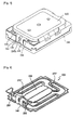
- FIG. 2 is a perspective view of a sound converter according to a first embodiment of the present invention
- FIG. 3 is a cut-away perspective view of the sound converter according to the first embodiment of the present invention.
- a yoke assembly 300 in which an inner ring magnet 320 and an outer ring magnet 330 are attached to a yoke plate 310, is coupled to a frame 110, then a damper 200, a center diaphragm 120 and a side diaphragm 130 are provided so that a voice coil 140 attached to the damper 200 can be positioned in a gap between the inner ring magnet 320 and the outer ring magnet 330.
- a protector 150 is provided to protect the diaphragms 120 and 130.
- a dome portion of the side diaphragm 130 projects to the bottom surface of the damper 200, i.e., in the mounting direction of the voice coil 140. Therefore, in the case of the voice coil 140 made of an electric wire having a large diameter to obtain high outputs, as the height of the voice coil 140 increases, the installation position of the voice coil 140 should be set higher so that it does not touch the yoke plate 310.
- the sound converter has a given limited height, which restricts the height of the upward dome portion of the side diaphragm 140.
- the dome portion of the side diaphragm 130 according to the present invention projects to the bottom surface where the voice coil is installed, thus having a sufficient space for projection.
- the side diaphragm 130 is prepared by laminating a polyetheretherketone(PEEK) film and a thermoplastic polyurethane (TPU) film.
- the thickness of the side diaphragm 130 should be decreased to improve low frequency band characteristics of the sound converter. The thinner the diaphragm, the more defects may occur during the manufacture.
- the TPU element which does not affect the rigidity of the diaphragm, i.e., the sound characteristics, is laminated with the PEEK element, which maintains rigidity and increases thickness. As a result, reliability of the diaphragm can be improved.
- the TPU film has an advantage in that it increases a damping ratio to improve dynamic characteristics of the sound.
- the voice coil 140 should be a lightweight aluminum alloy coil. The more the weight of the voice coil 140 decreases, the more the amplitude of the diaphragm 130 increases, resulting in high sound outputs.
- FIG. 4 is a perspective view of a damper provided in the sound converter according to the first embodiment of the present invention, when viewed from the top
- FIG. 5 is a perspective view of the damper provided in the sound converter according to the first embodiment of the present invention, when viewed from the bottom
- FIG. 6 is a perspective view showing a state where a voice coil is mounted under the damper provided in the sound converter according to the first embodiment of the present invention.
- the damper 200 provided in the sound converter according to the first embodiment of the present invention includes a central portion 210 formed at the center in a certain shape, a seating portion 220 spaced apart from the central portion 210 and seated on the frame 110, and a connection portion 230 elastically connecting the seating portion 220 to the central portion 210.
- the central portion 210 of the damper 200 can serve as the center diaphragm 120, so that the center diaphragm 120 is not necessary.
- the weight of the central portion 210 serving as the center diaphragm 120 is smaller than that of the central portion 210 provided with the center diaphragm 120, which can improve mid and high frequency band sound characteristics.
- the center diaphragm 120 may be formed in an upward dome shape and attached to the upper part of the central portion 210 of the damper 200, or the center diaphragm 120 may be formed in a downward dome shape and attached to the lower part of the central portion 210 of the damper 200.
- connection portion 230 aids the central portion 210 to perform only the vertical motion by the vibration of the voice coil 140, thereby preventing split vibration and improving mid and high frequency band sound characteristics.
- Parts of the connection portion 230 which are connected directly to the central portion 210 and the seating portion 220, are perpendicular thereto and have a relatively small length, so that the central portion 210 can perform only the vertical motion.
- a part between the parts connected perpendicularly to the central portion 210 and the seating portion 220 is in parallel thereto and have a relatively large length.
- connection portion 230 of the damper 200 is not necessarily connected perpendicularly to the central portion 210 and the seating portion 220 and is not necessarily in parallel to the central portion 210 and the seating portion 220. It is preferable that the connection portion 230 should be relatively long to lower rigidity in the vertical direction and should have a symmetric structure to eliminate biased vibration in the lateral direction.
- a conductive pattern 260 may be formed on the bottom surface of the damper 200, i.e., the mounting surface of the voice coil 140.
- a soldering or welding portion 270 for electrically connecting a leader wire of the voice coil 140 to the conductive pattern 260 is provided at the central portion 210.
- the leader wire of the voice coil 140 is electrically connected to the soldering or welding portion 270 by means of soldering or welding.
- the damper 200 itself may be an FPCB with an electric transfer structure pattern.
- the use of the conductive pattern 260 removes the necessity of taking the leader wire of the voice coil 140 out of the frame 110 and connecting it to a terminal. Furthermore, as the leader wire is extended to the frame, it is possible to prevent the leader wire from being broken by vibration of the diaphragms 120 and 130 and the damper 200 caused by the voice coil 140.
- the damper 200 with the conductive pattern 260 formed thereon includes an extended portion having one end exposed to the outside of the frame 110.
- the extended portion includes a bonding portion 240 bent on one side of the seating portion 220 to surround the lateral surface of the frame 110 and a terminal portion 250 providing an electrical contact with an external connection terminal. Therefore, the conductive pattern is connected between the welding portion 270 and the terminal portion 250, so the damper 200 provides an electrical connection between the external connection terminal and the voice coil 140 without using a special structure.
- a groove 160 is formed in the frame 110 to guide the bonding portion 240.
- the bonding portion 240 is thermally bonded to the frame 110 to secure the terminal portion 250.
- the frame 110 has a projection 170 to thermally bond the bonding portion 240, and the bonding portion 240 has a hole 240h into which the projection 170 for thermal bonding is to be inserted.
- the terminal portion 250 and the frame 110 have a groove and a projection corresponding to each other in shape, respectively.
- FIG. 7 is a perspective view of a sound converter according to a second embodiment of the present invention, when viewed from the bottom.
- a bonding portion 240 and a terminal portion 250 of a damper 200 are exposed to lateral and bottom surfaces of a frame 110, so that the terminal portion 250 can be connected to an external connection terminal. This also facilitates the bonding of the bonding portion 240 and the fixing of the terminal portion 250.
- FIG. 8 is a perspective view of a damper provided in the sound converter according to the second embodiment of the present invention, when viewed from the bottom.
- the damper 200 provided in the sound converter according to the second embodiment of the present invention includes a central portion 210 formed at the center in a certain shape, a seating portion 220 spaced apart from the central portion 210 and seated on the frame 110, and a connection portion 230 elastically connecting the seating portion 220 to the central portion 210.
- the bonding portion 240, the terminal portion 250 and the conductive pattern 260 of the damper 200 are identical to those of the damper 200 provided in the sound converter according to the first embodiment of the present invention.
- a soldering or welding portion 270' to which a leader wire of a voice coil 140 is to be soldered or welded is provided at the connection portion 230.
- the conductive pattern 260 provided in the sound converter according to the second embodiment of the present invention is formed up to the central portion 210 of the damper 200.
- the soldering or welding portion 270' is provided at the connection portion 230 as in the second embodiment, the conductive pattern 260 may be formed up to the soldering or welding portion 270' and may not be formed at the central portion 210.
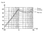
- FIG. 9 is a graph showing characteristics of an inventive sound converter versus characteristics of a conventional sound converter having an upward dome. In comparison, the sound characteristics of the inventive sound converter have been more improved in the whole frequency bands than those of the conventional sound converter.
Abstract
Description
- The present invention relates to a sound converter, and, more particularly, to a sound converter which can solve a problem in that a vibration space decreases in the sound converter requiring high outputs, as the overall height of a voice coil increases.
- In general, a sound converter is used as a concept including a speaker, etc. The speaker converts electrical energy into mechanical energy through a voice coil present in a void according to Fleming's left hand rule to thereby generate sound.
- That is, when a current signal containing various frequencies is applied to the voice coil, the voice coil produces mechanical energy according to the intensity of the current and the magnitude of the frequency, causes vibration to a diaphragm attached to the voice coil, and ultimately generates a given magnitude of sound pressure which can be recognized by human ears.
- A magnetic circuit of the speaker is designed in a yoke made of a ferrous metal element so that a magnetic flux can be interlinked perpendicularly to the voice coil present in the void by using a magnet (permanent magnet) and a top plate (or upper plate). The voice coil is adhered to the diaphragm to generate an electromotive force in the vertical direction according to an input signal, which vibrates the diaphragm adhered to and constrained by a frame to generate sound pressure.
- The diaphragm is provided with various forms of waves to attain an excellent response and prevent a buckling phenomenon during the vertical vibration. The shape of the diaphragm is a factor which has the most significant effect on frequency characteristics.
-
FIG. 1 is a sectional view of a conventional sound converter. - As illustrated in
FIG. 1 , the typical sound converter includes a frame 1, ayoke 2 inserted into and mounted in the frame 1, aninner ring magnet 3 and an outer ring magnet 4 transferring the magnetic flux to theyoke 2 or receiving the magnetic flux from theyoke 2, an innerring top plate 5 and an outerring top plate 6 receiving the magnetic flux from theinner ring magnet 3 or the outer ring magnet 4 and transferring the magnetic flux perpendicularly to avoice coil 7, thevoice coil 7 partially inserted into a void between theinner ring magnet 3 and the innerring top plate 5 and the outer ring magnet 4 and the outerring top plate 6, adiaphragm 8 having thevoice coil 7 attached thereto to generate vibration according to the vertical motion of thevoice coil 7, and aprotector 10 having asound emission hole 11 and protecting thediaphragm 8. - Additionally, a lead-out wire of the
voice coil 7 is fixedly attached to the bottom surface of thediaphragm 8 by a bond, taken out through the lateral surface of the frame 1 or through a groove (not shown) formed in the frame 1, and soldered to aterminal 14 along the outer lateral surface of the frame 1. - In the conventional sound converter described above, an electric wire forming the
voice coil 7 is made of a thick material so as to increase outputs, which increases the overall height of thevoice coil 7. Accordingly, a space below thevoice coil 7 should be so large that thevoice coil 7 can be vibrated in the vertical direction to cause vibration to thediaphragm 8. To this end, if thevoice coil 7 is made of a thick material to increase outputs, it needs to be positioned higher. For this, a seating portion of thediaphragm 8 should also be positioned higher. As a result, if the entire size of the sound converter does not increase, there is no sufficient vibration space for the upward dome-shaped diaphragm 8. - Moreover, even if the wire material of the coil is not thickened on account of mid frequency efficiency characteristics by weight, the amplitude of the diaphragm increases in a high-output mode, which requires efficient space utilization. Once the vibration space is obtained, the magnetic circuit space decreases, which degrades characteristics.
- In another case, an aluminum alloy coil having a small specific gravity is used to improve mid frequency efficiency characteristics by its weight. This coil is often broken due to low strength, which results in low reliability.
- An object of the present invention is to provide a sound converter which can solve a problem in that a vibration space decreases, as the overall height of a voice coil increases, said voice coil having a large wire diameter to increase outputs of the sound converter.
- Another object of the present invention is to provide a structure for efficiently utilizing a vibration space without decreasing the size of a magnetic circuit to ensure a sufficient vibration space in high outputs.
- A further object of the present invention is to provide a sound converter which includes a damper for preventing biased vibration from occurring, when outputs of the sound converter increase, said damper having a conductive pattern formed thereon, such as FPCB, to arrange a leader wire withdrawal structure of a voice coil.
- A still further object of the present invention is to provide a sound converter which includes a damper with a conductive pattern formed thereon, such as FPCB, said damper being taken out of the frame and serving as a terminal brought into contact with an external connection terminal.
- A still further object of the present invention is to provide a sound converter which includes a diaphragm made of a laminate of different materials to improve rigidity and reliability.
- According to an aspect of the present invention, there is provided a sound converter including: a frame; a yoke assembly provided on one side of the frame and provided with a magnet; a diaphragm provided in the frame to generate vibration; a protector provided over the diaphragm, coupled to the frame, and protecting the diaphragm; a damper having a central portion formed at the center in a certain shape, a seating portion spaced apart from the central portion and seated on the frame, and a connection portion elastically connecting the seating portion to the central portion; a side diaphragm having an inner circumference portion overlapping with the edge of the central portion of the damper and an outer circumference portion overlapping with the seating portion and seated on the frame, said diaphragm being formed in a dome shape having a central portion more projecting than the inner circumference portion and the outer circumference portion; and a voice coil mounted on the overlapping portion of the inner circumference portion of the side diaphragm and the central portion of the damper, wherein the projecting direction of the dome shape of the side diaphragm is the mounting direction of the voice coil.
- In addition, the sound converter may further include a center diaphragm attached to an upper part of the central portion of the damper.
- Moreover, the center diaphragm may project to the lower side or the upper side.
- Additionally, the damper may have a conductive pattern formed thereon.
- Further, the damper with the conductive pattern formed thereon may be an FPCB.
- Furthermore, a soldering or welding portion may be provided at the central portion of the damper to connect a leader wire of the voice coil.
- Still furthermore, the soldering or welding portion may be positioned at the connection portion of the damper.
- Still furthermore, the damper may include a terminal portion extending from one side of the seating portion, exposed to the outside of the frame, and providing an electrical connection with an external connection terminal.
- Still furthermore, the soldering or welding portion may be positioned on the inside of a voice coil attachment portion.
- Still furthermore, the extended portion of the damper may be bent along the lateral surface of the frame and attached to the bottom surface of the frame.
- Still furthermore, a groove may be formed in the frame to guide the extended portion of the damper.
- Still furthermore, a projection may be formed on the lateral surface of the frame to thermally bond a part of the damper.
- Still furthermore, a groove may be formed in the extended portion of the damper that corresponds to the thermal bonding projection of the frame.
- Still furthermore, the side diaphragm is prepared by laminating a thermoplastic polyurethane (TPU) film and a polyetheretherketone(PEEK) film.
- Still furthermore, the voice coil may be a lightweight aluminum alloy coil.
- Accordingly, in the sound converter provided by the present invention, since there is a sufficient vibration space, it can be designed to improve sound pressure in low frequency bands of large vibration displacement.
- In addition, in the sound converter provided by the present invention, since the lead-in wire of the voice coil is not connected directly to the outside, the aluminum-copper alloy coil having low strength can be employed without disconnection.
- Moreover, if outputs increase, biased vibration may occur. In the sound converter provided by the present invention, the damper with the conductive pattern formed thereon, such as FPCB, is used to prevent biased vibration, arrange the leader wire withdrawal structure of the voice coil, and prevent cutting of the leader wire connected to the terminal in high outputs, which reduces the defection rate.
- Additionally, in the sound converter provided by the present invention, the damper with the conductive pattern formed thereon, such as FPCB, is taken out of the frame and serves as a terminal brought into contact with the external connection terminal, which simplifies the assembly and cuts down the material costs.
- Further, in the sound converter provided by the present invention, the diaphragm is made of a laminate of different materials to improve rigidity and reliability.
- Furthermore, in the sound converter provided by the present invention, since the vibration space can be larger, sound pressure in low frequency bands, which require a large vibration space, can be increased to improve sound characteristics.
-
-
FIG. 1 is a view of a conventional sound converter. -
FIG. 2 is a perspective view of a sound converter according to a first embodiment of the present invention. -
FIG. 3 is a cut-away perspective view of the sound converter according to the first embodiment of the present invention. -
FIG. 4 is a perspective view of a damper provided in the sound converter according to the first embodiment of the present invention, when viewed from the top. -
FIG. 5 is a perspective view of the damper provided in the sound converter according to the first embodiment of the present invention, when viewed from the bottom. -
FIG. 6 is a perspective view showing a state where a voice coil is mounted under the damper provided in the sound converter according to the first embodiment of the present invention. -
FIG. 7 is a perspective view of a sound converter according to a second embodiment of the present invention, when viewed from the bottom. -
FIG. 8 is a perspective view of a damper provided in the sound converter according to the second embodiment of the present invention, when viewed from the bottom. -
FIG. 9 is a graph showing characteristics of an inventive sound converter versus characteristics of a conventional sound converter having an upward dome. -
FIG. 2 is a perspective view of a sound converter according to a first embodiment of the present invention, andFIG. 3 is a cut-away perspective view of the sound converter according to the first embodiment of the present invention. In the sound converter according to the first embodiment of the present invention, a yoke assembly 300, in which aninner ring magnet 320 and anouter ring magnet 330 are attached to ayoke plate 310, is coupled to aframe 110, then adamper 200, acenter diaphragm 120 and aside diaphragm 130 are provided so that avoice coil 140 attached to thedamper 200 can be positioned in a gap between theinner ring magnet 320 and theouter ring magnet 330. Next, aprotector 150 is provided to protect thediaphragms FIG. 3 , a dome portion of theside diaphragm 130 projects to the bottom surface of thedamper 200, i.e., in the mounting direction of thevoice coil 140. Therefore, in the case of thevoice coil 140 made of an electric wire having a large diameter to obtain high outputs, as the height of thevoice coil 140 increases, the installation position of thevoice coil 140 should be set higher so that it does not touch theyoke plate 310. Typically, the sound converter has a given limited height, which restricts the height of the upward dome portion of theside diaphragm 140. However, the dome portion of theside diaphragm 130 according to the present invention projects to the bottom surface where the voice coil is installed, thus having a sufficient space for projection. - Additionally, the
side diaphragm 130 according to the present invention is prepared by laminating a polyetheretherketone(PEEK) film and a thermoplastic polyurethane (TPU) film. The thickness of theside diaphragm 130 should be decreased to improve low frequency band characteristics of the sound converter. The thinner the diaphragm, the more defects may occur during the manufacture. To solve this problem, the TPU element, which does not affect the rigidity of the diaphragm, i.e., the sound characteristics, is laminated with the PEEK element, which maintains rigidity and increases thickness. As a result, reliability of the diaphragm can be improved. Moreover, the TPU film has an advantage in that it increases a damping ratio to improve dynamic characteristics of the sound. - Further, it is preferable that the
voice coil 140 should be a lightweight aluminum alloy coil. The more the weight of thevoice coil 140 decreases, the more the amplitude of thediaphragm 130 increases, resulting in high sound outputs. -
FIG. 4 is a perspective view of a damper provided in the sound converter according to the first embodiment of the present invention, when viewed from the top,FIG. 5 is a perspective view of the damper provided in the sound converter according to the first embodiment of the present invention, when viewed from the bottom, andFIG. 6 is a perspective view showing a state where a voice coil is mounted under the damper provided in the sound converter according to the first embodiment of the present invention. Thedamper 200 provided in the sound converter according to the first embodiment of the present invention includes acentral portion 210 formed at the center in a certain shape, aseating portion 220 spaced apart from thecentral portion 210 and seated on theframe 110, and aconnection portion 230 elastically connecting theseating portion 220 to thecentral portion 210. Thecentral portion 210 of thedamper 200 can serve as thecenter diaphragm 120, so that thecenter diaphragm 120 is not necessary. In this case, the weight of thecentral portion 210 serving as thecenter diaphragm 120 is smaller than that of thecentral portion 210 provided with thecenter diaphragm 120, which can improve mid and high frequency band sound characteristics. Meanwhile, in a case where thecenter diaphragm 120 is separately manufactured and attached to thecentral portion 210, thecenter diaphragm 120 may be formed in an upward dome shape and attached to the upper part of thecentral portion 210 of thedamper 200, or thecenter diaphragm 120 may be formed in a downward dome shape and attached to the lower part of thecentral portion 210 of thedamper 200. On the other hand, theconnection portion 230 aids thecentral portion 210 to perform only the vertical motion by the vibration of thevoice coil 140, thereby preventing split vibration and improving mid and high frequency band sound characteristics. Parts of theconnection portion 230, which are connected directly to thecentral portion 210 and theseating portion 220, are perpendicular thereto and have a relatively small length, so that thecentral portion 210 can perform only the vertical motion. A part between the parts connected perpendicularly to thecentral portion 210 and theseating portion 220 is in parallel thereto and have a relatively large length. However, it is to be noted that the shape of theconnection portion 230 of thedamper 200 is not necessarily connected perpendicularly to thecentral portion 210 and theseating portion 220 and is not necessarily in parallel to thecentral portion 210 and theseating portion 220. It is preferable that theconnection portion 230 should be relatively long to lower rigidity in the vertical direction and should have a symmetric structure to eliminate biased vibration in the lateral direction. - A
conductive pattern 260 may be formed on the bottom surface of thedamper 200, i.e., the mounting surface of thevoice coil 140. In addition, a soldering orwelding portion 270 for electrically connecting a leader wire of thevoice coil 140 to theconductive pattern 260 is provided at thecentral portion 210. The leader wire of thevoice coil 140 is electrically connected to the soldering orwelding portion 270 by means of soldering or welding. As an example of thedamper 200 with theconductive pattern 260 formed thereon, thedamper 200 itself may be an FPCB with an electric transfer structure pattern. The use of theconductive pattern 260 removes the necessity of taking the leader wire of thevoice coil 140 out of theframe 110 and connecting it to a terminal. Furthermore, as the leader wire is extended to the frame, it is possible to prevent the leader wire from being broken by vibration of thediaphragms damper 200 caused by thevoice coil 140. - In the meantime, the
damper 200 with theconductive pattern 260 formed thereon includes an extended portion having one end exposed to the outside of theframe 110. The extended portion includes abonding portion 240 bent on one side of theseating portion 220 to surround the lateral surface of theframe 110 and aterminal portion 250 providing an electrical contact with an external connection terminal. Therefore, the conductive pattern is connected between thewelding portion 270 and theterminal portion 250, so thedamper 200 provides an electrical connection between the external connection terminal and thevoice coil 140 without using a special structure. Agroove 160 is formed in theframe 110 to guide thebonding portion 240. In addition, thebonding portion 240 is thermally bonded to theframe 110 to secure theterminal portion 250. Theframe 110 has aprojection 170 to thermally bond thebonding portion 240, and thebonding portion 240 has ahole 240h into which theprojection 170 for thermal bonding is to be inserted. Moreover, theterminal portion 250 and theframe 110 have a groove and a projection corresponding to each other in shape, respectively. -
FIG. 7 is a perspective view of a sound converter according to a second embodiment of the present invention, when viewed from the bottom. Abonding portion 240 and aterminal portion 250 of adamper 200 are exposed to lateral and bottom surfaces of aframe 110, so that theterminal portion 250 can be connected to an external connection terminal. This also facilitates the bonding of thebonding portion 240 and the fixing of theterminal portion 250. -
FIG. 8 is a perspective view of a damper provided in the sound converter according to the second embodiment of the present invention, when viewed from the bottom. Thedamper 200 provided in the sound converter according to the second embodiment of the present invention includes acentral portion 210 formed at the center in a certain shape, aseating portion 220 spaced apart from thecentral portion 210 and seated on theframe 110, and aconnection portion 230 elastically connecting theseating portion 220 to thecentral portion 210. Thebonding portion 240, theterminal portion 250 and theconductive pattern 260 of thedamper 200 are identical to those of thedamper 200 provided in the sound converter according to the first embodiment of the present invention. In thedamper 200 provided in the sound converter according to the second embodiment of the present invention, a soldering or welding portion 270' to which a leader wire of avoice coil 140 is to be soldered or welded is provided at theconnection portion 230. Theconductive pattern 260 provided in the sound converter according to the second embodiment of the present invention is formed up to thecentral portion 210 of thedamper 200. However, if the soldering or welding portion 270' is provided at theconnection portion 230 as in the second embodiment, theconductive pattern 260 may be formed up to the soldering or welding portion 270' and may not be formed at thecentral portion 210. -
FIG. 9 is a graph showing characteristics of an inventive sound converter versus characteristics of a conventional sound converter having an upward dome. In comparison, the sound characteristics of the inventive sound converter have been more improved in the whole frequency bands than those of the conventional sound converter.
Claims (15)
- A sound converter, comprising:a frame;a yoke assembly provided on one side of the frame and provided with a magnet;a diaphragm provided in the frame to generate vibration;a protector provided over the diaphragm, coupled to the frame, and protecting the diaphragm;a damper having a central portion formed at the center in a certain shape, a seating portion spaced apart from the central portion and seated on the frame, and a connection portion elastically connecting the seating portion to the central portion;a side diaphragm having an inner circumference portion overlapping with the edge of the central portion of the damper and an outer circumference portion overlapping with the seating portion and seated on the frame, said diaphragm being formed in a dome shape having a central portion more projecting than the inner circumference portion and the outer circumference portion; anda voice coil mounted on the overlapping portion of the inner circumference portion of the side diaphragm and the central portion of the damper,wherein the projecting direction of the dome shape of the side diaphragm is the mounting direction of the voice coil.
- The sound converter of Claim 1, further comprising a center diaphragm attached to an upper part of the central portion of the damper.
- The sound converter of Claim 2, wherein the center diaphragm projects to the lower side or the upper side.
- The sound converter of Claim 1, wherein the damper has a conductive pattern formed thereon.
- The sound converter of Claim 4, wherein the damper with the conductive pattern formed thereon is an FPCB.
- The sound converter of Claim 4, wherein a soldering or welding portion is provided at the central portion of the damper to connect a leader wire of the voice coil.
- The sound converter of Claim 6, wherein the soldering or welding portion is positioned on the inside of a voice coil attachment portion.
- The sound converter of Claim 4, wherein a soldering or welding portion is provided at the connection portion of the damper to connect a leader wire of the voice coil.
- The sound converter of Claim 4, wherein the damper comprises an extended portion extending from one side of the seating portion and exposed to the outside of the frame and a terminal portion formed at an end of the extended portion to provide an electrical connection with an external connection terminal.
- The sound converter of Claim 9, wherein the extended portion of the damper is bent along the lateral surface of the frame and attached to the bottom surface of the frame.
- The sound converter of Claim 10, wherein a groove is formed in the frame to guide the extended portion of the damper.
- The sound converter of Claim 10, wherein a projection is formed on the lateral surface of the frame to thermally bond a part of the extended portion.
- The sound converter of Claim 12, wherein a groove is formed in the terminal portion of the damper that corresponds to the thermal bonding projection of the frame.
- The sound converter of Claim 1, wherein the side diaphragm is prepared by laminating a thermoplastic polyurethane (TPU) film and a polyetheretherketone(PEEK) film.
- The sound converter of Claim 1, wherein the voice coil is a lightweight aluminum alloy coil.
Applications Claiming Priority (2)
| Application Number | Priority Date | Filing Date | Title |
|---|---|---|---|
| KR20100079787 | 2010-08-18 | ||
| PCT/KR2011/005462 WO2012023709A2 (en) | 2010-08-18 | 2011-07-25 | Acoustic transducer device |
Publications (3)
| Publication Number | Publication Date |
|---|---|
| EP2490461A2 true EP2490461A2 (en) | 2012-08-22 |
| EP2490461A4 EP2490461A4 (en) | 2013-05-01 |
| EP2490461B1 EP2490461B1 (en) | 2017-03-01 |
Family
ID=45605494
Family Applications (1)
| Application Number | Title | Priority Date | Filing Date |
|---|---|---|---|
| EP11818309.4A Not-in-force EP2490461B1 (en) | 2010-08-18 | 2011-07-25 | Acoustic transducer device |
Country Status (5)
| Country | Link |
|---|---|
| US (1) | US8794374B2 (en) |
| EP (1) | EP2490461B1 (en) |
| KR (1) | KR101248977B1 (en) |
| CN (1) | CN102598709B (en) |
| WO (1) | WO2012023709A2 (en) |
Cited By (7)
| Publication number | Priority date | Publication date | Assignee | Title |
|---|---|---|---|---|
| EP2797341A1 (en) * | 2013-04-24 | 2014-10-29 | Em-tech. Co., Ltd. | Suspension for sound transducer |
| EP2797342A1 (en) * | 2013-04-25 | 2014-10-29 | Em-tech. Co., Ltd. | Bonding structure of diaphragm for microspeaker |
| CN104485094A (en) * | 2014-12-30 | 2015-04-01 | 哈尔滨固泰电子有限责任公司 | Contactless electronic loudspeaker with pure aluminum wire driving coil |
| US9532145B2 (en) | 2010-12-23 | 2016-12-27 | Eagle Acoustics Manufacturing, Llc | Low-profile speaker |
| EP2701402B1 (en) * | 2012-08-24 | 2019-11-13 | Em-tech. Co., Ltd. | Suspension for high power micro speaker, and high power micro speaker having the same |
| CN111818432A (en) * | 2020-08-31 | 2020-10-23 | 歌尔股份有限公司 | Loudspeaker |
| CN111935618A (en) * | 2020-08-31 | 2020-11-13 | 歌尔股份有限公司 | Loudspeaker |
Families Citing this family (32)
| Publication number | Priority date | Publication date | Assignee | Title |
|---|---|---|---|---|
| KR101200435B1 (en) * | 2011-05-13 | 2012-11-12 | 주식회사 이엠텍 | High power micro speaker |
| CN102595262A (en) * | 2012-02-22 | 2012-07-18 | 歌尔声学股份有限公司 | Sounder module and assembling method thereof |
| KR101330112B1 (en) * | 2012-03-30 | 2013-11-15 | 주식회사 이엠텍 | Dynamic receiver |
| KR101318698B1 (en) * | 2012-03-30 | 2013-10-16 | 주식회사 이엠텍 | Micro speaker |
| KR101345367B1 (en) * | 2012-05-03 | 2013-12-30 | 주식회사 이엠텍 | Diaphragm for sound transducer |
| KR101339868B1 (en) * | 2012-05-14 | 2013-12-10 | 주식회사 이엠텍 | Sound transducer |
| KR101213682B1 (en) * | 2012-06-08 | 2012-12-18 | 태경에프앤씨 주식회사 | Laminating film of polymer film and tpu for diaphragm material of audio device and thereof |
| KR101363408B1 (en) * | 2012-07-30 | 2014-02-18 | 주식회사 이엠텍 | Suspension for a sound transducer |
| KR101353440B1 (en) * | 2012-08-13 | 2014-01-22 | 주식회사 이엠텍 | A sound converting apparatus |
| US9900703B2 (en) | 2012-08-23 | 2018-02-20 | Em-Tech. Co., Ltd. | Suspension for high power micro speaker and high power micro speaker having the same |
| CN103686549B (en) * | 2012-09-14 | 2016-12-21 | 易音特电子株式会社 | The suspension of high power micro-speaker and the high power micro-speaker with suspension |
| DE112014003033T5 (en) * | 2013-06-25 | 2016-03-24 | Knowles Ipc (M) Sdn. Bhd. | Hearing aid compatible mobile phone speaker |
| CN103763667B (en) * | 2013-12-31 | 2017-10-13 | 瑞声声学科技(深圳)有限公司 | Multifunctional electroacoustic device |
| KR102269152B1 (en) * | 2014-10-07 | 2021-06-25 | 삼성전자주식회사 | Speaker |
| KR101556525B1 (en) | 2014-12-15 | 2015-10-05 | 주식회사 이엠텍 | Vent structure of the slim microspeaker |
| CN104822111B (en) * | 2015-03-31 | 2018-10-12 | 歌尔股份有限公司 | A kind of loud speaker module |
| CN105072541B (en) * | 2015-07-17 | 2018-09-25 | 歌尔股份有限公司 | A kind of magnetic circuit system and loud speaker for loud speaker |
| CN206136268U (en) * | 2016-06-15 | 2017-04-26 | 瑞声声学科技(深圳)有限公司 | Micro sound production device |
| KR101788112B1 (en) | 2017-02-06 | 2017-10-20 | 주식회사 이엠텍 | High-pressure water resist microspeaker with improved coil structure |
| CN108882122A (en) * | 2017-05-11 | 2018-11-23 | 易音特电子株式会社 | High power micro-speaker with sub- vibrating diaphragm |
| USD842845S1 (en) * | 2017-08-21 | 2019-03-12 | Henan Province Hozel Electronics Co., Ltd. | Housing for a voice coil motor used in a focusing product |
| USD855590S1 (en) * | 2017-10-27 | 2019-08-06 | Haibo Ql | Home speaker mount |
| CN108430010A (en) * | 2018-01-27 | 2018-08-21 | 瑞声科技(新加坡)有限公司 | Microphone device |
| CN108810767B (en) * | 2018-08-03 | 2020-11-17 | 瑞声科技(新加坡)有限公司 | Loudspeaker and manufacturing method thereof |
| CN208798197U (en) * | 2018-08-03 | 2019-04-26 | 瑞声科技(新加坡)有限公司 | Loudspeaker |
| CN208798196U (en) * | 2018-08-03 | 2019-04-26 | 瑞声科技(新加坡)有限公司 | Flexible circuit board and loudspeaker with the flexible circuit board |
| CN109246561B (en) * | 2018-09-21 | 2020-01-14 | 歌尔股份有限公司 | Sound generating device and electronic equipment |
| USD879749S1 (en) * | 2018-11-01 | 2020-03-31 | Shenzhen Zhiyuan Tongtai Technology Co., Ltd. | Home speaker mount |
| CN109996158A (en) * | 2018-12-26 | 2019-07-09 | 江苏米笛声学科技有限公司 | Superlinearity Microspeaker |
| KR102252025B1 (en) * | 2019-06-05 | 2021-05-17 | 주식회사 이엠텍 | Sound producing actuator |
| CN110401906A (en) * | 2019-08-27 | 2019-11-01 | 常州紫浩电子有限公司 | Patch loudspeaker |
| USD887397S1 (en) * | 2020-02-24 | 2020-06-16 | Qin Wang | Speaker wall mount |
Citations (1)
| Publication number | Priority date | Publication date | Assignee | Title |
|---|---|---|---|---|
| WO2010050068A1 (en) * | 2008-10-31 | 2010-05-06 | パイオニア株式会社 | Speaker device, and automobile |
Family Cites Families (18)
| Publication number | Priority date | Publication date | Assignee | Title |
|---|---|---|---|---|
| JPH09307993A (en) * | 1996-05-15 | 1997-11-28 | Kenwood Corp | Damper for speaker |
| US6490363B1 (en) * | 1999-10-13 | 2002-12-03 | Chun-I Liu | Structure of speaker |
| JP2001211499A (en) * | 2000-01-25 | 2001-08-03 | Pioneer Electronic Corp | Manufacture of damper and speaker unit using the damper |
| JP2002152882A (en) * | 2000-11-06 | 2002-05-24 | Citizen Electronics Co Ltd | Manufacturing method for micro speaker and the micro speaker by the method |
| JP2003001191A (en) | 2001-06-21 | 2003-01-07 | Nec Tokin Corp | Multi-functional vibration actuator |
| JP3971625B2 (en) * | 2002-02-25 | 2007-09-05 | フォスター電機株式会社 | Thin speaker and manufacturing method thereof |
| KR100419915B1 (en) * | 2002-08-30 | 2004-02-25 | 주식회사 진영음향 | Dynamic micro speaker with dual suspension |
| KR200298314Y1 (en) * | 2002-09-02 | 2002-12-16 | 유옥정 | Dynamic micro speaker with dual suspension |
| JP3989856B2 (en) * | 2003-02-27 | 2007-10-10 | パイオニア株式会社 | Speaker device |
| KR100419914B1 (en) | 2003-03-17 | 2004-02-25 | 주식회사 진영음향 | A Vibration Module for Micro Speaker and Micro Speaker with the same |
| JP4159408B2 (en) * | 2003-05-26 | 2008-10-01 | パイオニア株式会社 | Speaker |
| JP2005252922A (en) * | 2004-03-08 | 2005-09-15 | Matsushita Electric Ind Co Ltd | Speaker and manufacturing method thereof |
| US20090060254A1 (en) * | 2006-01-24 | 2009-03-05 | Matsushita Electric Industrial Co., Ltd. | Speaker and electronic apparatus and device using the same |
| US20080166010A1 (en) * | 2007-01-04 | 2008-07-10 | Stiles Enrique M | Overlapping surround roll for loudspeaker |
| CN102187687B (en) * | 2008-10-15 | 2014-09-03 | 易音特电子株式会社 | Diaphragm for sound converter and sound converter including the same |
| KR101033867B1 (en) * | 2008-10-15 | 2011-05-11 | 주식회사 이엠텍 | Diaphrahm for sound converter |
| KR101047549B1 (en) * | 2009-06-24 | 2011-07-07 | 주식회사 비에스이 | Multifunction micro speaker |
| KR100930537B1 (en) | 2009-09-03 | 2009-12-09 | 주식회사 블루콤 | Micro speaker including a structure of uniting an vibration plate for high power |
-
2011
- 2011-07-25 CN CN201180004402.3A patent/CN102598709B/en not_active Expired - Fee Related
- 2011-07-25 WO PCT/KR2011/005462 patent/WO2012023709A2/en active Application Filing
- 2011-07-25 US US13/635,176 patent/US8794374B2/en active Active
- 2011-07-25 EP EP11818309.4A patent/EP2490461B1/en not_active Not-in-force
- 2011-08-11 KR KR1020110080048A patent/KR101248977B1/en active IP Right Grant
Patent Citations (1)
| Publication number | Priority date | Publication date | Assignee | Title |
|---|---|---|---|---|
| WO2010050068A1 (en) * | 2008-10-31 | 2010-05-06 | パイオニア株式会社 | Speaker device, and automobile |
Non-Patent Citations (1)
| Title |
|---|
| See also references of WO2012023709A2 * |
Cited By (11)
| Publication number | Priority date | Publication date | Assignee | Title |
|---|---|---|---|---|
| US9532145B2 (en) | 2010-12-23 | 2016-12-27 | Eagle Acoustics Manufacturing, Llc | Low-profile speaker |
| EP2701402B1 (en) * | 2012-08-24 | 2019-11-13 | Em-tech. Co., Ltd. | Suspension for high power micro speaker, and high power micro speaker having the same |
| EP2797341A1 (en) * | 2013-04-24 | 2014-10-29 | Em-tech. Co., Ltd. | Suspension for sound transducer |
| US9185477B2 (en) | 2013-04-24 | 2015-11-10 | Em-Tech Co., Ltd. | Suspension for sound transducer |
| EP2797342A1 (en) * | 2013-04-25 | 2014-10-29 | Em-tech. Co., Ltd. | Bonding structure of diaphragm for microspeaker |
| US9027700B2 (en) | 2013-04-25 | 2015-05-12 | Em-Tech. Co., Ltd. | Bonding structure of diaphragm for microspeaker |
| CN104485094A (en) * | 2014-12-30 | 2015-04-01 | 哈尔滨固泰电子有限责任公司 | Contactless electronic loudspeaker with pure aluminum wire driving coil |
| CN104485094B (en) * | 2014-12-30 | 2018-10-26 | 哈尔滨固泰电子有限责任公司 | Using the contactless electronic loudspeaker of pure aluminum wire driving coil |
| CN111818432A (en) * | 2020-08-31 | 2020-10-23 | 歌尔股份有限公司 | Loudspeaker |
| CN111935618A (en) * | 2020-08-31 | 2020-11-13 | 歌尔股份有限公司 | Loudspeaker |
| CN111818432B (en) * | 2020-08-31 | 2020-12-08 | 歌尔股份有限公司 | Loudspeaker |
Also Published As
| Publication number | Publication date |
|---|---|
| KR101248977B1 (en) | 2013-04-01 |
| WO2012023709A3 (en) | 2012-04-12 |
| EP2490461B1 (en) | 2017-03-01 |
| KR20120017404A (en) | 2012-02-28 |
| CN102598709A (en) | 2012-07-18 |
| US8794374B2 (en) | 2014-08-05 |
| CN102598709B (en) | 2014-12-24 |
| US20130133975A1 (en) | 2013-05-30 |
| EP2490461A4 (en) | 2013-05-01 |
| WO2012023709A2 (en) | 2012-02-23 |
Similar Documents
| Publication | Publication Date | Title |
|---|---|---|
| EP2490461B1 (en) | Acoustic transducer device | |
| KR101200435B1 (en) | High power micro speaker | |
| CN108401215B (en) | High-voltage waterproof micro loudspeaker with improved coil structure | |
| US10827276B2 (en) | Micro-speaker | |
| CN101489169A (en) | Speaker unit | |
| JP4159408B2 (en) | Speaker | |
| KR101142253B1 (en) | A sound converting apparatus | |
| WO2021012611A1 (en) | Ultra-thin loudspeaker | |
| KR101255586B1 (en) | High power acoustic transducer | |
| CN109743662B (en) | Centering support piece and sound production device | |
| KR101166727B1 (en) | A sound converting apparatus | |
| KR101481649B1 (en) | Microspeaker | |
| CN107147976B (en) | Acoustic generator and electronic device comprising same | |
| TW201129122A (en) | Multi-function micro-speaker | |
| CN213462288U (en) | Sound production device | |
| KR20130004464A (en) | High power acoustic transducer | |
| KR101195020B1 (en) | An acoustic tranducer | |
| KR101468630B1 (en) | Diaphragm module and micro-speaker having the same | |
| WO2019205658A1 (en) | Sound producing device, sound producing module, and electronic terminal | |
| KR101353440B1 (en) | A sound converting apparatus | |
| CN112261556B (en) | Sound production device | |
| JP3235735U (en) | Bone conduction handset and electronic device with the bone conduction handset | |
| KR101369331B1 (en) | Sound transducer | |
| KR101012862B1 (en) | Sound converter | |
| KR101475341B1 (en) | Slim microspeaker |
Legal Events
| Date | Code | Title | Description |
|---|---|---|---|
| PUAI | Public reference made under article 153(3) epc to a published international application that has entered the european phase |
Free format text: ORIGINAL CODE: 0009012 |
|
| 17P | Request for examination filed |
Effective date: 20120515 |
|
| AK | Designated contracting states |
Kind code of ref document: A2 Designated state(s): AL AT BE BG CH CY CZ DE DK EE ES FI FR GB GR HR HU IE IS IT LI LT LU LV MC MK MT NL NO PL PT RO RS SE SI SK SM TR |
|
| A4 | Supplementary search report drawn up and despatched |
Effective date: 20130403 |
|
| RIC1 | Information provided on ipc code assigned before grant |
Ipc: H04R 9/02 20060101ALI20130326BHEP Ipc: H04R 7/16 20060101AFI20130326BHEP Ipc: H04R 9/06 20060101ALI20130326BHEP Ipc: H04R 9/04 20060101ALI20130326BHEP |
|
| DAX | Request for extension of the european patent (deleted) | ||
| REG | Reference to a national code |
Ref country code: DE Ref legal event code: R079 Ref document number: 602011035520 Country of ref document: DE Free format text: PREVIOUS MAIN CLASS: H04R0007160000 Ipc: H04R0007040000 |
|
| RIC1 | Information provided on ipc code assigned before grant |
Ipc: H04R 9/06 20060101ALI20160823BHEP Ipc: H04R 9/04 20060101ALI20160823BHEP Ipc: H04R 7/16 20060101ALI20160823BHEP Ipc: H04R 7/04 20060101AFI20160823BHEP Ipc: G10K 13/00 20060101ALI20160823BHEP |
|
| GRAP | Despatch of communication of intention to grant a patent |
Free format text: ORIGINAL CODE: EPIDOSNIGR1 |
|
| INTG | Intention to grant announced |
Effective date: 20161004 |
|
| RAP1 | Party data changed (applicant data changed or rights of an application transferred) |
Owner name: EM-TECH CO., LTD. |
|
| STAA | Information on the status of an ep patent application or granted ep patent |
Free format text: STATUS: GRANT OF PATENT IS INTENDED |
|
| GRAS | Grant fee paid |
Free format text: ORIGINAL CODE: EPIDOSNIGR3 |
|
| GRAA | (expected) grant |
Free format text: ORIGINAL CODE: 0009210 |
|
| STAA | Information on the status of an ep patent application or granted ep patent |
Free format text: STATUS: THE PATENT HAS BEEN GRANTED |
|
| AK | Designated contracting states |
Kind code of ref document: B1 Designated state(s): AL AT BE BG CH CY CZ DE DK EE ES FI FR GB GR HR HU IE IS IT LI LT LU LV MC MK MT NL NO PL PT RO RS SE SI SK SM TR |
|
| REG | Reference to a national code |
Ref country code: GB Ref legal event code: FG4D |
|
| REG | Reference to a national code |
Ref country code: CH Ref legal event code: EP Ref country code: AT Ref legal event code: REF Ref document number: 872573 Country of ref document: AT Kind code of ref document: T Effective date: 20170315 |
|
| REG | Reference to a national code |
Ref country code: IE Ref legal event code: FG4D |
|
| REG | Reference to a national code |
Ref country code: DE Ref legal event code: R096 Ref document number: 602011035520 Country of ref document: DE |
|
| REG | Reference to a national code |
Ref country code: NL Ref legal event code: MP Effective date: 20170301 |
|
| REG | Reference to a national code |
Ref country code: LT Ref legal event code: MG4D |
|
| REG | Reference to a national code |
Ref country code: AT Ref legal event code: MK05 Ref document number: 872573 Country of ref document: AT Kind code of ref document: T Effective date: 20170301 |
|
| PG25 | Lapsed in a contracting state [announced via postgrant information from national office to epo] |
Ref country code: HR Free format text: LAPSE BECAUSE OF FAILURE TO SUBMIT A TRANSLATION OF THE DESCRIPTION OR TO PAY THE FEE WITHIN THE PRESCRIBED TIME-LIMIT Effective date: 20170301 Ref country code: LT Free format text: LAPSE BECAUSE OF FAILURE TO SUBMIT A TRANSLATION OF THE DESCRIPTION OR TO PAY THE FEE WITHIN THE PRESCRIBED TIME-LIMIT Effective date: 20170301 Ref country code: GR Free format text: LAPSE BECAUSE OF FAILURE TO SUBMIT A TRANSLATION OF THE DESCRIPTION OR TO PAY THE FEE WITHIN THE PRESCRIBED TIME-LIMIT Effective date: 20170602 Ref country code: FI Free format text: LAPSE BECAUSE OF FAILURE TO SUBMIT A TRANSLATION OF THE DESCRIPTION OR TO PAY THE FEE WITHIN THE PRESCRIBED TIME-LIMIT Effective date: 20170301 Ref country code: NO Free format text: LAPSE BECAUSE OF FAILURE TO SUBMIT A TRANSLATION OF THE DESCRIPTION OR TO PAY THE FEE WITHIN THE PRESCRIBED TIME-LIMIT Effective date: 20170601 |
|
| PG25 | Lapsed in a contracting state [announced via postgrant information from national office to epo] |
Ref country code: ES Free format text: LAPSE BECAUSE OF FAILURE TO SUBMIT A TRANSLATION OF THE DESCRIPTION OR TO PAY THE FEE WITHIN THE PRESCRIBED TIME-LIMIT Effective date: 20170301 Ref country code: SE Free format text: LAPSE BECAUSE OF FAILURE TO SUBMIT A TRANSLATION OF THE DESCRIPTION OR TO PAY THE FEE WITHIN THE PRESCRIBED TIME-LIMIT Effective date: 20170301 Ref country code: AT Free format text: LAPSE BECAUSE OF FAILURE TO SUBMIT A TRANSLATION OF THE DESCRIPTION OR TO PAY THE FEE WITHIN THE PRESCRIBED TIME-LIMIT Effective date: 20170301 Ref country code: RS Free format text: LAPSE BECAUSE OF FAILURE TO SUBMIT A TRANSLATION OF THE DESCRIPTION OR TO PAY THE FEE WITHIN THE PRESCRIBED TIME-LIMIT Effective date: 20170301 Ref country code: LV Free format text: LAPSE BECAUSE OF FAILURE TO SUBMIT A TRANSLATION OF THE DESCRIPTION OR TO PAY THE FEE WITHIN THE PRESCRIBED TIME-LIMIT Effective date: 20170301 Ref country code: BG Free format text: LAPSE BECAUSE OF FAILURE TO SUBMIT A TRANSLATION OF THE DESCRIPTION OR TO PAY THE FEE WITHIN THE PRESCRIBED TIME-LIMIT Effective date: 20170601 |
|
| PG25 | Lapsed in a contracting state [announced via postgrant information from national office to epo] |
Ref country code: NL Free format text: LAPSE BECAUSE OF FAILURE TO SUBMIT A TRANSLATION OF THE DESCRIPTION OR TO PAY THE FEE WITHIN THE PRESCRIBED TIME-LIMIT Effective date: 20170301 |
|
| PG25 | Lapsed in a contracting state [announced via postgrant information from national office to epo] |
Ref country code: SK Free format text: LAPSE BECAUSE OF FAILURE TO SUBMIT A TRANSLATION OF THE DESCRIPTION OR TO PAY THE FEE WITHIN THE PRESCRIBED TIME-LIMIT Effective date: 20170301 Ref country code: IT Free format text: LAPSE BECAUSE OF FAILURE TO SUBMIT A TRANSLATION OF THE DESCRIPTION OR TO PAY THE FEE WITHIN THE PRESCRIBED TIME-LIMIT Effective date: 20170301 Ref country code: CZ Free format text: LAPSE BECAUSE OF FAILURE TO SUBMIT A TRANSLATION OF THE DESCRIPTION OR TO PAY THE FEE WITHIN THE PRESCRIBED TIME-LIMIT Effective date: 20170301 Ref country code: RO Free format text: LAPSE BECAUSE OF FAILURE TO SUBMIT A TRANSLATION OF THE DESCRIPTION OR TO PAY THE FEE WITHIN THE PRESCRIBED TIME-LIMIT Effective date: 20170301 Ref country code: EE Free format text: LAPSE BECAUSE OF FAILURE TO SUBMIT A TRANSLATION OF THE DESCRIPTION OR TO PAY THE FEE WITHIN THE PRESCRIBED TIME-LIMIT Effective date: 20170301 |
|
| PG25 | Lapsed in a contracting state [announced via postgrant information from national office to epo] |
Ref country code: SM Free format text: LAPSE BECAUSE OF FAILURE TO SUBMIT A TRANSLATION OF THE DESCRIPTION OR TO PAY THE FEE WITHIN THE PRESCRIBED TIME-LIMIT Effective date: 20170301 Ref country code: IS Free format text: LAPSE BECAUSE OF FAILURE TO SUBMIT A TRANSLATION OF THE DESCRIPTION OR TO PAY THE FEE WITHIN THE PRESCRIBED TIME-LIMIT Effective date: 20170701 Ref country code: PT Free format text: LAPSE BECAUSE OF FAILURE TO SUBMIT A TRANSLATION OF THE DESCRIPTION OR TO PAY THE FEE WITHIN THE PRESCRIBED TIME-LIMIT Effective date: 20170703 Ref country code: PL Free format text: LAPSE BECAUSE OF FAILURE TO SUBMIT A TRANSLATION OF THE DESCRIPTION OR TO PAY THE FEE WITHIN THE PRESCRIBED TIME-LIMIT Effective date: 20170301 |
|
| REG | Reference to a national code |
Ref country code: DE Ref legal event code: R097 Ref document number: 602011035520 Country of ref document: DE |
|
| PLBE | No opposition filed within time limit |
Free format text: ORIGINAL CODE: 0009261 |
|
| STAA | Information on the status of an ep patent application or granted ep patent |
Free format text: STATUS: NO OPPOSITION FILED WITHIN TIME LIMIT |
|
| PG25 | Lapsed in a contracting state [announced via postgrant information from national office to epo] |
Ref country code: DK Free format text: LAPSE BECAUSE OF FAILURE TO SUBMIT A TRANSLATION OF THE DESCRIPTION OR TO PAY THE FEE WITHIN THE PRESCRIBED TIME-LIMIT Effective date: 20170301 |
|
| 26N | No opposition filed |
Effective date: 20171204 |
|
| PG25 | Lapsed in a contracting state [announced via postgrant information from national office to epo] |
Ref country code: SI Free format text: LAPSE BECAUSE OF FAILURE TO SUBMIT A TRANSLATION OF THE DESCRIPTION OR TO PAY THE FEE WITHIN THE PRESCRIBED TIME-LIMIT Effective date: 20170301 |
|
| REG | Reference to a national code |
Ref country code: CH Ref legal event code: PL |
|
| GBPC | Gb: european patent ceased through non-payment of renewal fee |
Effective date: 20170725 |
|
| REG | Reference to a national code |
Ref country code: IE Ref legal event code: MM4A |
|
| REG | Reference to a national code |
Ref country code: FR Ref legal event code: ST Effective date: 20180330 |
|
| PG25 | Lapsed in a contracting state [announced via postgrant information from national office to epo] |
Ref country code: GB Free format text: LAPSE BECAUSE OF NON-PAYMENT OF DUE FEES Effective date: 20170725 Ref country code: CH Free format text: LAPSE BECAUSE OF NON-PAYMENT OF DUE FEES Effective date: 20170731 Ref country code: LI Free format text: LAPSE BECAUSE OF NON-PAYMENT OF DUE FEES Effective date: 20170731 Ref country code: IE Free format text: LAPSE BECAUSE OF NON-PAYMENT OF DUE FEES Effective date: 20170725 |
|
| PG25 | Lapsed in a contracting state [announced via postgrant information from national office to epo] |
Ref country code: FR Free format text: LAPSE BECAUSE OF NON-PAYMENT OF DUE FEES Effective date: 20170731 |
|
| REG | Reference to a national code |
Ref country code: BE Ref legal event code: MM Effective date: 20170731 |
|
| PG25 | Lapsed in a contracting state [announced via postgrant information from national office to epo] |
Ref country code: LU Free format text: LAPSE BECAUSE OF NON-PAYMENT OF DUE FEES Effective date: 20170725 |
|
| PG25 | Lapsed in a contracting state [announced via postgrant information from national office to epo] |
Ref country code: BE Free format text: LAPSE BECAUSE OF NON-PAYMENT OF DUE FEES Effective date: 20170731 |
|
| PG25 | Lapsed in a contracting state [announced via postgrant information from national office to epo] |
Ref country code: MT Free format text: LAPSE BECAUSE OF NON-PAYMENT OF DUE FEES Effective date: 20170725 |
|
| PG25 | Lapsed in a contracting state [announced via postgrant information from national office to epo] |
Ref country code: HU Free format text: LAPSE BECAUSE OF FAILURE TO SUBMIT A TRANSLATION OF THE DESCRIPTION OR TO PAY THE FEE WITHIN THE PRESCRIBED TIME-LIMIT; INVALID AB INITIO Effective date: 20110725 Ref country code: MC Free format text: LAPSE BECAUSE OF FAILURE TO SUBMIT A TRANSLATION OF THE DESCRIPTION OR TO PAY THE FEE WITHIN THE PRESCRIBED TIME-LIMIT Effective date: 20170301 |
|
| PG25 | Lapsed in a contracting state [announced via postgrant information from national office to epo] |
Ref country code: CY Free format text: LAPSE BECAUSE OF NON-PAYMENT OF DUE FEES Effective date: 20170301 |
|
| PG25 | Lapsed in a contracting state [announced via postgrant information from national office to epo] |
Ref country code: MK Free format text: LAPSE BECAUSE OF FAILURE TO SUBMIT A TRANSLATION OF THE DESCRIPTION OR TO PAY THE FEE WITHIN THE PRESCRIBED TIME-LIMIT Effective date: 20170301 |
|
| PG25 | Lapsed in a contracting state [announced via postgrant information from national office to epo] |
Ref country code: TR Free format text: LAPSE BECAUSE OF FAILURE TO SUBMIT A TRANSLATION OF THE DESCRIPTION OR TO PAY THE FEE WITHIN THE PRESCRIBED TIME-LIMIT Effective date: 20170301 |
|
| PG25 | Lapsed in a contracting state [announced via postgrant information from national office to epo] |
Ref country code: AL Free format text: LAPSE BECAUSE OF FAILURE TO SUBMIT A TRANSLATION OF THE DESCRIPTION OR TO PAY THE FEE WITHIN THE PRESCRIBED TIME-LIMIT Effective date: 20170301 |
|
| PGFP | Annual fee paid to national office [announced via postgrant information from national office to epo] |
Ref country code: DE Payment date: 20210726 Year of fee payment: 11 |
|
| REG | Reference to a national code |
Ref country code: DE Ref legal event code: R119 Ref document number: 602011035520 Country of ref document: DE |
|
| PG25 | Lapsed in a contracting state [announced via postgrant information from national office to epo] |
Ref country code: DE Free format text: LAPSE BECAUSE OF NON-PAYMENT OF DUE FEES Effective date: 20230201 |