EP2486907A1 - Patient Support Apparatus Including Storage Structure - Google Patents
Patient Support Apparatus Including Storage Structure Download PDFInfo
- Publication number
- EP2486907A1 EP2486907A1 EP12151513A EP12151513A EP2486907A1 EP 2486907 A1 EP2486907 A1 EP 2486907A1 EP 12151513 A EP12151513 A EP 12151513A EP 12151513 A EP12151513 A EP 12151513A EP 2486907 A1 EP2486907 A1 EP 2486907A1
- Authority
- EP
- European Patent Office
- Prior art keywords
- frame
- deck section
- support
- patient
- storage structure
- Prior art date
- Legal status (The legal status is an assumption and is not a legal conclusion. Google has not performed a legal analysis and makes no representation as to the accuracy of the status listed.)
- Granted
Links
- 230000007246 mechanism Effects 0.000 claims abstract description 58
- 230000007704 transition Effects 0.000 claims description 4
- 230000001419 dependent effect Effects 0.000 claims 1
- 230000006378 damage Effects 0.000 abstract description 5
- 239000012190 activator Substances 0.000 description 13
- 230000000712 assembly Effects 0.000 description 11
- 238000000429 assembly Methods 0.000 description 11
- 210000002826 placenta Anatomy 0.000 description 11
- 238000000034 method Methods 0.000 description 5
- 230000000295 complement effect Effects 0.000 description 4
- 239000000463 material Substances 0.000 description 4
- 230000000717 retained effect Effects 0.000 description 4
- 239000000758 substrate Substances 0.000 description 4
- 238000006073 displacement reaction Methods 0.000 description 3
- 230000008569 process Effects 0.000 description 3
- 239000004744 fabric Substances 0.000 description 2
- 239000004033 plastic Substances 0.000 description 2
- 238000005096 rolling process Methods 0.000 description 2
- JOYRKODLDBILNP-UHFFFAOYSA-N Ethyl urethane Chemical compound CCOC(N)=O JOYRKODLDBILNP-UHFFFAOYSA-N 0.000 description 1
- 239000004677 Nylon Substances 0.000 description 1
- 208000031481 Pathologic Constriction Diseases 0.000 description 1
- 208000027418 Wounds and injury Diseases 0.000 description 1
- 239000000853 adhesive Substances 0.000 description 1
- 230000001070 adhesive effect Effects 0.000 description 1
- 230000004888 barrier function Effects 0.000 description 1
- 230000008859 change Effects 0.000 description 1
- 230000006835 compression Effects 0.000 description 1
- 238000007906 compression Methods 0.000 description 1
- 230000008878 coupling Effects 0.000 description 1
- 238000010168 coupling process Methods 0.000 description 1
- 238000005859 coupling reaction Methods 0.000 description 1
- 230000000694 effects Effects 0.000 description 1
- 208000014674 injury Diseases 0.000 description 1
- 238000003780 insertion Methods 0.000 description 1
- 230000037431 insertion Effects 0.000 description 1
- 239000002184 metal Substances 0.000 description 1
- 229920001778 nylon Polymers 0.000 description 1
- 230000000284 resting effect Effects 0.000 description 1
- 239000002699 waste material Substances 0.000 description 1
- 239000002759 woven fabric Substances 0.000 description 1
Images


Classifications
-
- A—HUMAN NECESSITIES
- A61—MEDICAL OR VETERINARY SCIENCE; HYGIENE
- A61G—TRANSPORT, PERSONAL CONVEYANCES, OR ACCOMMODATION SPECIALLY ADAPTED FOR PATIENTS OR DISABLED PERSONS; OPERATING TABLES OR CHAIRS; CHAIRS FOR DENTISTRY; FUNERAL DEVICES
- A61G13/00—Operating tables; Auxiliary appliances therefor
- A61G13/0009—Obstetrical tables or delivery beds
-
- A—HUMAN NECESSITIES
- A61—MEDICAL OR VETERINARY SCIENCE; HYGIENE
- A61G—TRANSPORT, PERSONAL CONVEYANCES, OR ACCOMMODATION SPECIALLY ADAPTED FOR PATIENTS OR DISABLED PERSONS; OPERATING TABLES OR CHAIRS; CHAIRS FOR DENTISTRY; FUNERAL DEVICES
- A61G7/00—Beds specially adapted for nursing; Devices for lifting patients or disabled persons
- A61G7/002—Beds specially adapted for nursing; Devices for lifting patients or disabled persons having adjustable mattress frame
- A61G7/015—Beds specially adapted for nursing; Devices for lifting patients or disabled persons having adjustable mattress frame divided into different adjustable sections, e.g. for Gatch position
-
- A—HUMAN NECESSITIES
- A61—MEDICAL OR VETERINARY SCIENCE; HYGIENE
- A61G—TRANSPORT, PERSONAL CONVEYANCES, OR ACCOMMODATION SPECIALLY ADAPTED FOR PATIENTS OR DISABLED PERSONS; OPERATING TABLES OR CHAIRS; CHAIRS FOR DENTISTRY; FUNERAL DEVICES
- A61G7/00—Beds specially adapted for nursing; Devices for lifting patients or disabled persons
- A61G7/05—Parts, details or accessories of beds
- A61G7/0528—Steering or braking devices for castor wheels
-
- A—HUMAN NECESSITIES
- A61—MEDICAL OR VETERINARY SCIENCE; HYGIENE
- A61G—TRANSPORT, PERSONAL CONVEYANCES, OR ACCOMMODATION SPECIALLY ADAPTED FOR PATIENTS OR DISABLED PERSONS; OPERATING TABLES OR CHAIRS; CHAIRS FOR DENTISTRY; FUNERAL DEVICES
- A61G7/00—Beds specially adapted for nursing; Devices for lifting patients or disabled persons
- A61G7/05—Parts, details or accessories of beds
- A61G7/065—Rests specially adapted therefor
- A61G7/075—Rests specially adapted therefor for the limbs
- A61G7/0755—Rests specially adapted therefor for the limbs for the legs or feet
-
- Y—GENERAL TAGGING OF NEW TECHNOLOGICAL DEVELOPMENTS; GENERAL TAGGING OF CROSS-SECTIONAL TECHNOLOGIES SPANNING OVER SEVERAL SECTIONS OF THE IPC; TECHNICAL SUBJECTS COVERED BY FORMER USPC CROSS-REFERENCE ART COLLECTIONS [XRACs] AND DIGESTS
- Y10—TECHNICAL SUBJECTS COVERED BY FORMER USPC
- Y10T—TECHNICAL SUBJECTS COVERED BY FORMER US CLASSIFICATION
- Y10T74/00—Machine element or mechanism
- Y10T74/21—Elements
- Y10T74/2101—Cams
Definitions
- the hanger assemblies may be moveable relative to the upper frame along a longitudinal length of the patient-support apparatus such that the storage structure is moveable relative to the upper frame.
- the hanger assemblies may be biased to a first position away from the foot end of the patient-support apparatus.
- the storage structure may be configured to engage with the lower frame of the patient -support apparatus to overcome the bias exerted on the hanger assemblies and urge the storage structure toward a foot end of the patient-support apparatus when the upper frame is articulated vertically downward toward the lower frame.
- a receiver 46 is coupled to support frame 22 by three bolts 48.
- Receiver 46 is configured to assist a user, such as a caregiver, to engage a removable foot deck section such as foot deck section 16 to support frame 22 by guiding a support plate 50 to proper engagement with receiver 46 to support foot deck section 16 in cantilever from support frame 22.
- a second receiver 52 is positioned on support frame 22 and is positioned laterally opposite of receiver 46.
- Receiver 52 is also secured to support frame 22 by three bolts 48 and receiver 50 is positioned to receive a second support plate 54 which is positioned on foot deck section 16 laterally opposite of support plate 50.
- the cavity formed in upper deck 36 of seat section 14 may be a U-shaped cavity and support 180 may be replaced with another support member which is configured to be received within the U-shaped cavity and support a U-shaped protrusion of a cushion assembly supported on a foot deck section configured to be received in the U-shaped cavity.
- cross-member 444 is free to move relative to brackets 460 and 462.
- frame 407 rotates about shaft 432 and surfaces 438 and 440 are urged against surface 442.
- cross-member 444 compresses springs 450 and 452 to allow frame 407 to deflect.
- frame 407 is urged to return to a position in which extensions 408 and 410 are in a generally horizontal orientation.
- Activator 364 also extends through a plate 742 that provides rigidity to cushion assembly 362.
- the plates 740 and 742 in the illustrative embodiment comprise a semi rigid plastic material.
- Cushion assembly 362 further comprises a grip handle 744 that comprises a woven nylon fabric and is secured to plate 742.
- grip handle 744 has a loop 746 and a strap 748 passing through a first aperture 750 and being fed through a second aperture 752 and through a third aperture 754 and then back upon itself so that the strap be is secured to plate 742 by a hook and loop fastener 756, best seen in Fig. 9 .
- loop 746 is formed by securing a portion of the woven fabric material back upon itself and securing it with yet another hook and loop fastener
Abstract
Description
- This disclosure rotates to a patient-support apparatuses and accessories. Specifically, this disclosure relates to patient-support apparatuses with articulating deck sections that are removable and stowable.
- Patient-support apparatuses, including hospital beds and birching beds, sometimes provide support for patients during medical procedures. In the case of birching beds, the apparatus supports the mother throughout the labor and delivery of a child. During the procedures or birthing process, it is sometimes advantageous to move or remove a portion of the patient-support apparatus to allow a caregiver, such as a doctor or nurse, improved access to a portion of the patient's body. For example, in the case of a birthing bed, a foot deck section may be removable to permit a caregiver access to the perineal area of a mother during labor to assist with the delivery of the child.
- The present invention comprises an apparatus or a system that has one or more of the following features or combinations thereof.
- According to the present disclosure, a patient-support apparatus embodied as a birthing bed comprises a lower frame, an upper frame which raises a towers relative to the lower frame, and support frame which moves relative to the upper frame. The patient-support apparatus further comprises a deck section releasably coupleable to the support frame, and a storage structure coupled to the support frame and the upper frame, the support frame configured to support the deck section as the deck section moves between a use position, wherein the deck section is secured to the support frame and a stored position between the lower frame and upper frame. In some embodiments, the deck section may include a locking mechanism actuable to engage with a portion of the support frame to secure the deck section to the support frame.
- In some embodiments, the locking mechanism may be activated by a cushion assembly positioned on the deck section. The cushion assembly may include a protrusion configured to engage the locking mechanism to actuate the locking mechanism into engagement with the support frame to secure the deck section to the support frame. The locking mechanism may be biased to a position in which an engagement pin of the locking mechanism is retracted within the frame of the foot deck section. The protrusion may be configured to actuate a linkage to overcome the bias of the locking mechanism to urge the engagement pin to extend and engage a portion of the support frame to secure the foot deck section to the support frame.
- The storage structure may comprise bias assembly supported from the upper frame of the patient-support apparatus, a frame coupled to the bias assembly, and a guide engaged with the frame and pivotably coupled to the support frame. The guide may be configured to support the deck section during movement of the deck section between a use position and a stowed position. The guide may move with the support frame and along the frame of the storage structure to provide a continuous support structure for supporting the foot deck section.
- The frame may be moveable relative to the upper frame to deflect under a load placed on the foot deck section in a stowed position. The bias assembly may comprise springs which urge the frame of the storage structure to a home position wherein the frame is configured to maintain the foot deck section in a generally horizontal storage position. The bias assembly may be coupled to hanger assemblies which are engaged with a portion of the upper frame.
- The hanger assemblies may be moveable relative to the upper frame along a longitudinal length of the patient-support apparatus such that the storage structure is moveable relative to the upper frame. The hanger assemblies may be biased to a first position away from the foot end of the patient-support apparatus. The storage structure may be configured to engage with the lower frame of the patient -support apparatus to overcome the bias exerted on the hanger assemblies and urge the storage structure toward a foot end of the patient-support apparatus when the upper frame is articulated vertically downward toward the lower frame.
- The storage structure may be configured to position the foot deck section in a position wherein a portion of the foot deck section is exposed. The exposed portion of the foot deck section may be formed to include a receptacle which is positioned to be accessed by a caregiver when the foot deck section is in a stowed position. The receptacle may be embodied as a placenta basin and may be positioned to be accessed by a caregiver during the birthing process.
- In another illustrative embodiment, a patient support apparatus comprises a frame having first and second members, first and second receivers coupled to the first and second members respectively, and a patient-support deck including first and second support brackets configured to engage with the first and second receivers to support the patient-support deck on the frame of the patient-support apparatus. The receivers may comprise a first protrusion forming a generally vertical boundary and a second protrusion spaced apart from the first protrusion to form another generally vertical boundary. A lower generally vertical surface positioned may be interposed between the first and second protrusions. An inclined surface may be interposed between the first and second protrusions, the inclined surface spaced vertically above the lower surface and intersecting the lower surface.
- The patient-support deck may comprise a main portion having first and second lateral sides. The first and second support brackets may be coupled to the main portion and positioned on the first and second sides, respectively. The second side may be positioned laterally opposite the first support bracket. The brackets may be configured to engage the first and second receivers to support and secure the patient-support deck.
- In some embodiments, the first and second support brackets may be positioned proximate an end of the patient-support deck. The patient-support deck may be supported in a cantilevered configuration. The receivers may be positioned on opposing lateral sides of a longitudinal axis of the patient-support apparatus. The patient-support apparatus may comprise a birching bed, and the patient-support deck may comprise a foot deck section.
- In some embodiments, the patient-support deck may comprise a pair of handles. The handles may be positioned on opposite lateral sides of the patient-support deck. In some embodiments, the handles may be a flexible material. The support brackets may include a protrusion configured to engage a lower surface of a protrusion on the receivers to maintain the patient-support deck in engagement with the patient-support apparatus if the patient-support deck is lifted from an end opposite the receivers.
- In some embodiments, the first and second support brackets comprise a bearing material positioned to engage with the inclined and lower surfaces of the first and second and receivers as the patient-support deck is positioned on the patient-support apparatus. In some embodiments, the receivers may comprise a generally horizontal support surface and a latch block. The patient-support deck may comprise a looking mechanism including latch hooks positioned to engage the latch blocks of the receivers to secure the patient-support deck to the patient-support apparatus.
- When the patient-support deck includes the locking mechanism, the handles may be rotatable to move the latch hooks a disengaged position and a position wherein the latch hooks are engaged to with the latch blocks to secure the patient-support deck to the patient-support apparatus. For example, the locking mechanism may comprise a first shaft coupled to a handle and an arm coupled to the shaft and moveable with the shaft. The locking mechanism may also comprise a second shaft coupled to the latch hook and arms coupled to the shafts and rotatable with the shafts and a link pivotably coupled to the arms at points offset from the axis of rotation of the shafts. The rotation of the handles may be transferred through the mechanism to rotate the latch hooks.
- The invention will now be described by way of example with reference to the accompanying drawings in which:
-
Fig. 1 is a perspective view of a birthing bed including articulable foot supports in a stowed position and a removable foot section; -
Fig. 2 is a perspective view of a portion of a birthing bed with portions removed, the birthing bed viewed from the foot end of the bed with a stowable foot deck section shown articulated to a stowed position such that a receptacle in the stowable foot deck section is positioned to function as a placenta basin; -
Fig. 3 is a side view of the stowable foot deck section ofFig. 2 including a cushion assembly secured on the foot deck section; -
Fig. 4 is a an exploded perspective assembly view of the stowable foot deck section ofFig. 3 , the foot deck section viewed from above; -
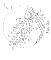
Fig. 5 is an exploded perspective assembly view of the foot deck section similar toFig. 4 , the foot deck section viewed from below inFig. 5 ; -
Fig. 5A is an enlarged view of a portion ofFig. 5 enclosed in a circle inFig. 5 ; -
Fig. 6 is a perspective view of the cushion assembly configured to be supported on the foot deck section, the cushion assembly including a protrusion configured to be received by the stowable foot deck section to activate a locking mechanism to secure the stowable foot deck section in use position on the birching bed; -
Fig. 7 is a side view of the cushion assembly ofFig. 6 ; -
Fig. 8 is a bottom view of a storage structure of the cushion assembly ofFig. 6 ; -
Fig. 9 is a side view of the storage structure ofFig. 8 ; -
Fig. 10 is a perspective view of a portion of a birthing bed having an embodiment of a guide system which guides the stowable foot deck section from a use position to be supported on a storage structure -
Fig. 11 is a perspective view of a portion of the birthing bed ofFig. 2 with portions removed, perspective view showing a receiver mounted to a frame of the birthing bed, the receiver configured to receive a portion of the stowable foot deck section in a cantilevered configuration; -
Fig. 12 is a view similar toFig. 11 ,Fig. 12 showing an alternative embodiment of receiver configured to receive a removable foot deck section; -
Fig. 13 is an exploded perspective assembly view of a structure coupled to a portion of the birthing bed ofFig. 2 , the structure configured to support the stowable foot deck section in a stowed position.; -
Fig. 14 is a perspective view of a portion of the storage structure ofFig. 13 ; -
Fig. 15 is an exploded perspective assembly view of the portion of the storage structure ofFig. 14 ; -
Fig. 16 is an exploded assembly view of a portion of the birthing bed ofFig. 1 with a removable foot deck section; -
Fig. 16A is an enlarged view of a portion ofFig. 16 enclosed in a circle 16A; -
Fig. 17 is a perspective view of the removable foot deck section stored positioned on a floor in an out-of-the-way position; -
Fig. 18 is a side view of the removable foot deck section; -
Fig. 19 is a side view of a tab of the removable foot section ofFig. 16 positioned to engage the receiver shown inFig. 12 ; -
Fig. 20 is a cross-sectional view of the receiver ofFigs. 12 ,16 , and19 The cross-section taken along lines 20-20 ofFig. 19 ; -
Fig. 21 is a perspective view of a portion of a birching bed inducting another embodiment of a foot deck section, the removable foot deck section including a locking mechanism to secure the removable foot deck section to a frame of the birthing bed; -
Fig. 22 is a perspective view of the removable foot deck section ofFig. 21 , the foot deck section viewed from below; -
Fig. 23 is a perspective view of a portion of a frame of the birthing bed ofFig. 21 , the frame configured to be engaged by the locking mechanism to secure; -
Fig. 24 is a perspective view of a portion of a birthing bed having yet another embodiment of a removable foot deck section; -
Fig. 25 is a perspective view of yet another embodiment of removable foot deck section, the foot deck section having a self-deploying stand to support the foot deck section when it is positioned on the floor; -
Fig. 26 is a perspective view of yet another removable foot deck section, the foot deck section including a deployable support frame with caster wheels such that the foot deck section may be rolled away from a birthing bed to which the foot deck section is engaged; -
Fig. 27 is a perspective view of a portion of the guide shown inFig. 10 ; -
Fig. 28 is a side view of the guide ofFig. 27 ; -
Fig. 29 is a cross-sectional view of the guide ofFig. 27 taken along lines 29-29 inFig. 28 ; -
Figs. 30- 40 are various perspective views of another embodiment of a birthing bed with portions removed, the birthing bed having a structure and guide system to support a stowable foot deck section in a use position and in a stowed position; -
Fig. 41 is perspective view of another embodiment of birthing bed, the birthing bed having a stowable foot deck section that folds and articulates to a stowed position; -
Fig. 42 is a perspective view of the stowable foot deck section ofFig. 41 in a stowed position; and -
Fig. 43 is a perspective exploded assembly view of another embodiment of a storage structure configured to support a foot deck section suspended from a frame of a patient-support apparatus. -
Fig. 1 shows abirthing bed 10 which comprises ahead deck section 12,seat deck section 14, and a removablefoot deck section 16 as shown inFig. 1 . Thebirthing bed 10 further comprises abase frame 18 supporting anintermediate frame 20 that supports thehead deck section 12 andseat deck section 14. Thehead deck section 12 andseat deck section 14 are articulable relative to theintermediate frame 20 to adjust the position of a patient occupying thebirthing bed 10. Thefoot deck section 14 is supported on asupport frame 22 that is supported by theintermediate frame 20. Thesupport frame 22 moves vertically as depicted byarrow 24 inFig. 1 to adjust to a plurality of positions including positions in which thefoot deck section 16 is vertically spaced from theseat deck section 14. This allows a caregiver or patient to adjust thebirthing bed 10 to a plurality of positions during labor and delivery. - The
birthing bed 10 comprises amattress 25 that is supported on thehead deck section 12 andseat deck section 14. Themattress 25 comprises a v-shapedcavity 26 along the edge of themattress 25 adjacent thefoot deck section 16. In the illustrative embodiment ofFig. 1 , acushion assembly 28 is supported on thefoot deck section 16 and comprises a protrusion 30 that is configured to be received in thecavity 26 to form a continuous support surface for a patient when thefoot deck section 16 is vertically aligned with theseat deck section 14. As is shown inFig. 1 , thebirthing bed 10 also comprises two articulable foot supports 32 and 34.Foot support 32 is positioned to support a patient's right foot when in use whilefoot support 34 is positioned to support a patient's left foot when in use. - In use during natural delivery of a baby, the
birthing bed 10 is configured to permit a caregiver access to a patient seated on themattress 25 and supported onseat deck section 14.Foot deck section 16 is supported on thesupport frame 22 and moveable with thesupport frame 22 as thesupport frame 22 moves vertically relative to theintermediate frame 20. - Referring now to
Fig. 16 , removablefoot deck section 16 and a portion ofbirthing bed 10 are shown in an exploded assembly view.Seat deck section 14 comprises anupper deck 36 which is supported on alower deck 38.Lower deck 38 included first andsecond pivots seat deck section 14 pivots relative tointermediate frame 20.Support frame 22 is supported relative tointermediate frame 20 and moves vertically relative tointermediate frame 20 as depicted byarrow 24.Support frame 22 is driven by a drive mechanism (not shown) which utilizes a DC drive to articulate an articulating mechanism 44 to control movement ofsupport frame 22. According to the present disclosure, the operation ofbirthing bed 10 including the articulation ofsupport frame 22 is consistent across all embodiments. However, in some embodiments supportframe 22 may be engaged by a receiver to change the configuration of thebirthing bed 10 such that alternative embodiments of foot support decks may be employed on thebirthing bed 10. - For example, referring to
Fig. 12 areceiver 46 is coupled to supportframe 22 by threebolts 48.Receiver 46 is configured to assist a user, such as a caregiver, to engage a removable foot deck section such asfoot deck section 16 to supportframe 22 by guiding asupport plate 50 to proper engagement withreceiver 46 to supportfoot deck section 16 in cantilever fromsupport frame 22. Referring again now toFig. 16 , asecond receiver 52 is positioned onsupport frame 22 and is positioned laterally opposite ofreceiver 46.Receiver 52 is also secured to supportframe 22 by threebolts 48 andreceiver 50 is positioned to receive asecond support plate 54 which is positioned onfoot deck section 16 laterally opposite ofsupport plate 50. Whensupport plates receivers foot deck section 16 is supported in cantilever fromsupport frame 22. As will be discussed in further detail below, the weight offoot deck section 16,cushion assembly 28, and the weight of a portion of a patient supported thereon, serves to increase the force with whichsupport plates receivers - Referring now to
Figs. 19-20 ,support plate 50 andreceiver 46 are illustratively shown.Receiver 46 has anupper surface 56 which transitions to anincline surface 58 which transitions to anengagement surface 60.Receiver 46 further includes afirst protrusion 62 and asecond protrusion 64. Whenreceiver 46 is coupled to structure 22,first protrusion 62 is positioned at a foot end to side ofreceiver 46 andprotrusion 64 is positioned at a head end ofreceiver 46. Protrusions 62 and 64 thereby serve as longitudinal barriers forsupport plate 50 whensupport plate 50 is engaged withreceiver 46. Generally,support plate 50 is narrower at a lower portion and widens as it progresses vertically upwardly, as shown inFigs. 19 . This tapering effect assists a caregiver in properly positioning the removablefoot deck section 16 longitudinally as thefoot deck section 16 is being positioned to engage withreceivers - Referring now to
Fig. 19 ,support plate 50 includes asurface 66 which engages asurface 68 of thesecond protrusion 64 assupport plate 50 is engaged withreceiver 46.Support plate 50 also includes a surface 70 which engages asurface 72 ofreceiver 46 whensupport plate 50 is engaged withreceiver 46.Support plate 50 has a vertical axis 74 and surfaces 66 and 70 are not parallel to vertical axis 74 or to each other. Assupport plate 50 is lowered in the direction of arrow 76surfaces 66 and 70 engagesurfaces support plate 50 is frictionally engaged withreceiver 46 thereby securing removablefoot deck section 16 to thebirthing bed 10. In addition, an outer surface 78 (not shown inFigs. 19-20 ) engages withsurface 58 which guidessupport plate 50 to proper engagement withsurface 60 ofreceiver 46. In the illustrative embodiment,support plate 50 is a mirror image to supportplate 54.Support plate 54 comprises amain portion 102 with anouter member 104 which is positioned to engagereceiver 52 and act as a bearing surface to reduce noise during the insertion ofsupport plate 50 intoreceiver 52, as well as to reduce noise which may occur whenfoot deck section 16 is moved due to patient movement onfoot support deck 16.Support plate 50 also includes a main portion 106 and an outer member 108. - Surface 70 of
support plate 50 is formed to include aprotrusion 80 which acts as a hook to prevent inadvertent removal offoot deck section 16 fromreceivers foot deck section 16 is lifted,protrusion 80 engages alower surface 82 offirst protrusion 62 ofreceiver 46. Thus, a person who is not familiar with the operation offoot deck section 16 is prevented from removingfoot deck section 16. In normal operation, a user grips twohandles foot deck section 16 to rotate so preventprotrusion 80 from clearingsurface 82 offirst protrusion 62.Foot deck section 16 includes amain portion 88 and handle 84 and 86 are coupled to opposite sides ofmain portion 88 byfasteners 90. -
Foot deck section 16 further includes fourextensions main portion 88 and extending laterally therefrom.Support bracket 50 is coupled toextensions support bracket 54 is coupled toextensions Extensions hole 100. Referring now toFig. 16A ,support plate 54 is shown to include a pair offlanges main portion 102. Two through-holes are formed in each of theflanges hole 114 and through-hole 116 are each formed inflange 110. Through-hole 118 and through-hole 120 are each formed inflange 112. Through-hole 114 is positioned vertically above through-hole 118 such that the centerlines of the through holes form an axis 122. Similarly, through-hole 116 is positioned vertically above through-hole 120 such that the centerlines of those through-holes form an axis 124. Whensupport plate 54 is coupled tomain portion 88 offoot deck sections 16, the axis 122 is positioned such that afastener 100 passes throughflange 110 throughprotrusion 92 and throughflange 112 along axis 122 and asecond fastener 100 passes along axis 124 throughflange 110,protrusion 94, andflange 112. Whenfastener 100 is engaged with support bracket 54 awasher 126 interfaces between ahead 128 of the fastener in theflange 110. Asecond washer 126 is interposed between anut 128 andflange 112. Tightening ofnut 128 ontofastener 100 securessupport bracket 54 toprotrusions foot deck 16.Support bracket 50 includes twoflanges protrusions bracket 54 is coupled toprotrusions -
Support bracket 54 further includes aglide 134 which is coupled tomain portion 102 and positioned to cover alower surface 138 ofmain portion 102.Glide 134 acts as a bearing assupport bracket 54 is engaged withreceiver 52 to reduce the potential for noise during the engagement ofsupport bracket 54 withreceiver 52.Support bracket 50 also includes aglide 140 coupled to main portion 106 and which acts in a manner or similar to glide 134 ofsupport bracket 54. -
Foot deck section 16 further includes astand 142 which is coupled tomain portion 88 by twofasteners 144. Stand 142 is illustratively embodied as a wire-form which is configured to supportfoot deck section 16 in a standing position. For example, in another illustrative embodiment shown inFig. 17 , astand 142 is coupled to afoot deck section 144 and supports thefoot deck section 144 in a standing position such that acushion assembly 146 is spaced apart from the floor to prevent linens supported on thecushion assembly 146 from being contaminated by touching the floor. The illustrativefoot deck section 144 is similar tofoot deck section 16, but thefoot deck section 144 has two grip handles 148 and 150 coupled to amain portion 152. Grip handles 148 and 150 are positioned such that a caregiver may utilize the grip handles 148 and 150 to repositionbirthing bed 10 by rolling thebirthing bed 10 oncasters 154 coupled to thebase 18 ofbirthing bed 10. - Referring again to
Fig. 16 ,foot deck section 16 further includes ahandle 156 coupled tomain portion 88. Handle 156 is usable by a caregiver to reposition thebirthing bed 10 by rolling it on itscasters 154. Handle 156 also serves as a stand to supportfoot deck section 16 in a standing position withhandle 156 engaging the floor. - In the illustrative embodiment of
Fig. 16 , aplacenta basin 158 is supported on tworacks frame 22 vertically belowreceivers Racks flange portions placenta basin 158 respectively. Ashroud 164 is coupled to supportframe 22 and has a shape which is configured to engage a front portion 170 ofplacenta basin 158 so thatshroud 164 andplacenta basin 158 cooperate to guide waste materials into theplacenta basin 158.Rack 116 includes twoextensions support frame 22 such thatrack 116 is coupled to supportframe 22 by a frictional interference fit. In some embodiments, an adhesive may be added to securerack 116 to supportframe 22. Similarly,rack 162 includes twoextensions support frame 22. -
Foot deck section 16 further includes asupport member 180 coupled tomain portion 88 and configured to provide support for a protrusion on a cushion assembly supported onfoot deck section 16 whenfoot deck section 16 is engaged withsupport frame 22.Support member 180 is illustratively embodied as a wire form having a V-shape and positioned to be received in a V-shaped cavity 182 formed anupper deck 36 ofseat section 14.Support member 180 is coupled tomain portion 88 by two fasteners 184 and washers 186. In other embodiments, the cavity formed inupper deck 36 ofseat section 14 may be a U-shaped cavity andsupport 180 may be replaced with another support member which is configured to be received within the U-shaped cavity and support a U-shaped protrusion of a cushion assembly supported on a foot deck section configured to be received in the U-shaped cavity. -
Foot deck section 144 shown inFigs. 17-18 is similar tofoot deck section 16 and illustrates the manner in which a cushion assembly, such ascushion assembly 146 may be coupled tofoot deck section 144 or other embodiments of foot deck sections, such asfoot deck section 16.Cushion assembly 146 includes aflap 188 which extends over the side offoot deck section 144 and includes twosnap portions 190 which engagecomplementary snap portions 192.Snap portions 192 are shown inFig. 16 which shows the engagement ofsnap portions 192 withmain portion 88 offoot deck section 16. Referring again toFig. 17 , another flap complementary toflap 188 and positioned laterally on the opposite side ofcushion assembly 146 includes a pair ofsnap portions 190 coupled to another pair ofsnap portions 192. In this manner,cushion assembly 146 is coupled tofoot deck section 144 and maintains engagement withfoot deck section 144 whenfoot deck section 144 is removed from engagement withreceivers cushion assembly 146 could be coupled tofoot deck section 16. -
Foot deck section 144. includes a pair of handles with one of thehandles 194 shown inFigs. 17 and18 . Thehandles including handle 194 are flexible and are positioned such that when a user liftsfoot deck section 144 off fromsupport frame 22 ofbirthing bed 10, the weight offoot deck section 144 urges the foot deck section to rotate withstand 142 in a vertically lowered orientation so that a caregiver may positionfoot deck section 144 in a standing position as shown inFig. 17 . - As discussed above,
foot deck sections foot deck sections birthing bed 10. In another embodiment shown inFigs. 21-23 , afoot deck section 196 is removable fromsupport frame 22 and includes a locking mechanism to positively securefoot deck section 196 to supportframe 22.Foot deck section 196 includes amain portion 198 with twosupport bracket assemblies main portion 198, In the illustrative embodiment ofFigs. 21-23 , only supportframe 22 is shown and the remainder ofbirthing bed 10 is omitted. However, it should be understood thatsupport 10frame 22 in the illustrative embodiments ofFigs. 21-23 is coupled tohospital bed 10 as described elsewhere in this disclosure.Support bracket 200 rests on a portion of areceiver 204 andsupport bracket 202 rests on a portion of areceiver 206 whenfoot deck section 196 is positioned onsupport frame 22. The engagement ofsupport bracket 202 toreceiver 206 is similar to the engagement ofsupport bracket 200 toreceiver 204 and will not be discussed in detail. The discussion of the engagement ofsupport bracket 200 toreceiver 204 should be extended to the engagement ofsupport bracket 202 toreceiver 206. -
Receiver 204 includes anupper portion 208 and alower portion 210.Upper portion 208 is formed to include a protrusion 212 having anupper surface 214, aguide surface 216, and avertical surface 218. Extension 212 extends over anupper surface 220 oflower portion 210 to form and undercut 222 which is configured to receive aroller 224 coupled to amain portion 226 ofsupport bracket 200. In addition,support bracket 200 includes aflange 228 which is positioned to engageupper surface 220 oflower portion 210 ofreceiver 204. Whenfoot deck section 196 is position onsupport frame 22,roller 224 is positioned in to undercut 222 andflange 228 rest onupper surface 220 oflower portion 210 such thatfoot deck section 196 is supported in a cantilevered orientation fromsupport frame 22. -
Foot deck section 196 further includes alocking mechanism 230 which transfers motion from a pair ofhandles lower portion 210 to securefoot deck section 196 to supportframe 22. For example,latch hook 236 rotates relative to supportbracket 200. Whensupport bracket 200 is engaged withreceiver 204,latch hook 236 is positioned above the cavity 238 in thelower portion 210 and rotates such that abarb 241 is positioned withincavity 240 beneath asurface 242.Cavity 240 andsurface 242 cooperate to define alatch block 243 which is engaged bybarb 241 to securefoot deck section 196 to supportframe 22. When in the locked position, thebarb 241 of 236 preventsfoot deck section 196 from being removed fromsupport frame 22.Handles shaft 242 which spans the width of themain portion 198 offoot deck section 196.Shaft 242 is supported onmain portion 198 through a pair ofbearings 244 which permitshaft 242 to rotate about its longitudinal length relative tomain portion 198 as depicted byarrow 246. -
Locking mechanism 230 further includes anarm 248 coupled toshaft 242 which rotates withshaft 242 whenshaft 242 is rotated byarms link 250 is pivotably coupled toarm 248 and is pivotably coupled to asecond arm 252.Arm 252 is coupled to ashaft 254 andlatch hook 236 is coupled toshaft 254 and rotates about the longitudinal length ofshaft 254 as depicted byarrow 256.Shaft 254 is coupled to anothershaft 258 through acoupler 260 which is coupled to each of the shafts by afastener 262 such that rotation ofshaft 256 is transferred toshaft 258 which thereby rotates another hook (not shown) positioned laterally oppositelatch hook 236.Shafts plates bearings 244. Becauselink 250 is pivotably coupled to throws 248 and 252 at a position that is offset from the longitudinal axis ofshafts shaft 242 is transferred toshaft 254 and therebyshaft 258. - Thus, actuation of
handles 232 and/or 234 rotateslatch hook 236 to engage withreceiver 204. Ashandles foot deck section 196. If the handles are rotated upwardly in the direction ofarrow 264 inFig. 21 ,latch hook 236 disengagesreceiver 200 andfoot deck section 196 is free to be removed from engagement withreceivers - The illustrative embodiment of
Fig. 24 , afoot deck section 266 supports acushion assembly 268 and is coupled to supportframe 22 ofbirching bed 10. Ahandle 273 includes amain portion 270 and agrip portion 272. Handle 273 is actuable in the direction ofarrow 274 to move to a stowed position with thegrip portion 272 stowed at the foot end ofdeck section 266 with grip portion positioned adjacent ahandle 271. Thefoot deck section 266 employs a locking mechanism similar tolocking mechanism 230 of the illustrative embodiment ofFigs. 21-23 , but the direction of travel ofhandle 273 is reversed as compared tohandles foot deck section 196. - In yet another embodiment illustrated in
Fig. 25 , a removablefoot deck section 280 includes amain portion 282 and twosupport brackets main portion 282 and configured to engagereceivers Fig. 16 , respectively.Foot deck section 280 includes ahandle 288 coupled tomain portion 282 and functions similarly to handle 156 offoot deck section 16. When coupled toreceivers foot deck section 280 functions similarly tofoot deck section 16. However,foot deck section 280 includes a three-point stand 290 which deploys whenfoot deck section 280 engages the floor. Stand 290 includes anupper bracket assembly 292 which is coupled to across-member 294 of themain portion 282 offoot deck section 280.Bracket assembly 292 includes tworeceivers link 300 such that thereceivers Bracket assembly 292 is pivotably coupled tocross-member 294 and pivots relative to cross-member 294 as depicted by anarrow 302. - Stand 290 further includes two
legs leg 304 being engaged withreceiver 296 andleg 306 been engaged withreceiver 298 such thatlegs bracket assembly 292. Acollar 308 is coupled toleg 304 and is configured to receive alink 312 for pivotable movement relative tocollar 308 and therebyleg 304. Similarly, acollar 310 is coupled toleg 306 and is configured to receive alink 314 such that thelink 314 is pivotable relative tocollar 310.Links bracket 316. Abias member 318 is also coupled tobracket 316 and is interposed betweenlinks Bias member 318 is coupled at an end oppositebracket 316 to cross-member 320 of themain portion 282 offoot deck section 280. Aflange 322 is also coupled tobracket 316 and is configured to engage with the floor whenfoot deck section 280 is lowered to the floor. Additionally, afoot 324 is coupled toflange 322 andbracket 316.Foot 324 is flexible and has a high coefficient of friction so that whenfoot 324 engages the floor, it provides resistance to deploystand 290. - Unloaded,
bias member 318 urgesbracket 316 to a stowed position wherein thebias member 318 pullslegs main portion 282 offoot deck section 280. Whenfoot 324 engages the floor and the weight afoot deck section 280 is borne byfoot 324 andflange 322,bias member 318 deflects in the direction ofarrow 326. Becauselinks bias member 318 causeslinks legs legs Fig. 25 . Once stand 290 is fully deployed,foot deck section 280 rests on twoglides legs foot 324. Ifbias member 318 is sufficiently deflected,foot deck section 280 may also rest onsupport brackets foot deck section 280 is lifted from the floor,bias member 318 urgesbracket 316 in the direction opposite ofarrow 326 and therebylinks legs main portion 282. - In still yet another embodiment shown in
Fig. 26 , a removablefoot deck section 332 is supported on ascissors frame 334 such thatfoot deck section 332 can be rolled away from a patient-support apparatus, such asbirthing bed 10.Scissors frame 334 includes fourcasters 336, two of which are coupled to alower member 338 and two of which are coupled to alower member 340.Scissors mechanism 334 further includes twolegs lower member 338 and pivotably coupled at a head end of amain portion 344 offoot deck section 332. Twolegs main portion 344 such thatlegs 346 are pivotable relative tomain portion 344. Additionally, one of each of thelegs 342 is pivotably coupled to one of the other pair oflegs 346 to form thescissors frame 334.Scissors frame 334 is manually deployed to engage the floor when a caregiver wants to removefoot deck section 332 from engagement withbirthing bed 10. Additionally,scissors frame 334 can be lifted to a stowed position manually whenfoot deck section 332 is engaged withbirthing bed 10. - A
support bracket 350 is coupled tomain portion 344 and is configured to slide onto a receiver (not shown) coupled to supportframe 22 ofbirthing bed 10. A matching support bracket is positioned laterally oppositesupport bracket 350 such that when the support brackets are engaged with the receivers,foot deck section 332 is supported in a cantilevered configuration fromsupport frame 22.Support bracket 350 includes abias member 352 which deflects whensupport bracket 350 is engaged with a receiver onsupport frame 22 untilbias member 352 is received in a cavity in the receiver. The cavity is complementary tobias member 352 and maintainsfoot deck section 332 in engagement withsupport frame 22 until sufficient force is applied to overcome the bias ofbias member 352 to remove thefoot deck section 332 fromsupport frame 22. - While various illustrative embodiments of removable foot deck sections have been disclosed herein, it should be understood that various aspects of the removable foot deck sections are interchangeable and various combinations of stands, locking mechanisms and handle configurations are contemplated within the scope of this disclosure. For example, in some embodiments a foot deck section similar to
foot deck section 16 may have a stand such asstand 142 omitted and may be supported in a standing orientation by a structure similar to stand 290 as disclosed in the illustrative embodiment ofFig. 25 . Similarly, in another embodiment a foot deck section such asfoot deck section 16 may be configured to employ the locking mechanism disclosed in the illustrative embodiment ofFigs. 21-23 . - In the embodiments discussed above, foot deck sections have been disclosed which are removal from birthing
bed 10 and storable in a position spaced apart from birthingbed 10. In some instances, it may be advantageous to stow a foot deck section within the space of abirthing bed 10 to reduce clutter within a delivery room and to reduce the potential for injury to a caregiver who lifts off a removable foot deck section. - Referring now to
Fig. 2 , in another embodiment of afoot deck section 360 is shown with acushion assembly 362 positioned on thefoot deck section 362.Cushion assembly 362 comprises anactuator 364 that extends from abottom surface 366 of cushion assembly 362 (best seen inFig. 6 ) and is received in anaperture 368 in an upper surface 370 offoot deck section 360. Theactuator 364 retainscushion assembly 362 onfoot deck section 360 and activates a locking mechanism 372 (best seen inFig. 4 ) which extends twopins 374 and 376 laterally outwardly from thefoot deck section 360 to engage with achannel 378 inreceiver 380 coupled to support frame 22 (refer toFig. 11 ). Thereceiver 380 is positioned on the patient right side ofbirthing bed 10, and asecond receiver 382 is positioned on the patient left side ofbirthing bed 10 as shown inFig. 2 . - The
foot deck section 360 engages withreceivers rollers rollers foot deck section 360 androllers foot deck section 360.Rollers deck section 360 by aretainers flange 910 which is received in an undercut 379 formed inchannel 378. Referring now toFig. 11 ,channel 378 intersects achannel 392. Whenfoot deck section 360 is positioned onsupport frame 22,roller 384 is positioned inchannel 378.Roller 386 is positioned on asurface 394 onreceiver 380 and thefoot deck section 360 is pivoted aboutroller 386 such thatroller 384 travels inchannel 378 untilroller 384 engages anend 396 ofchannel 378. Withroller 386 resting onsurface 394 androller 384. engaged withend 396,foot deck section 360 is supported in cantilever fromsupport frame 22. However, lifting of thefoot deck section 360 will result in thefoot deck section 360 moving relative to thereceiver 380. - To secure
foot deck section 360 toreceiver 380,pin 374 is extended into ablind cavity 398 formed in aninner surface 90 of thereceiver 380. Engagement ofpin 374 withcavity 398 prevents rotation offoot deck section 360 relative toreceiver 380. As will be discussed in further detail below,pin 374 extends fromfoot deck section 360 whencushion assembly 362 is positioned onfoot deck section 360 such that theactivator 364 ofcushion assembly 362 activates a locking mechanism 372 to extendpins 374 and 376. This securesfoot deck section 360 andcushion assembly 362 relative to supportframe 22 when thefoot deck section 360 is positioned onsupport frame 22 in use. - When not in use,
foot deck section 360 is stowable on astorage structure 400 as shown inFigs. 30-40 so that aplacenta basin 402 of thefoot deck section 360 is positioned for use during the labor and delivery process as shown inFig. 2 . A portion ofstorage structure 400 is shown inFig. 13 .Storage structure 400 is configured to receive and supportfoot deck section 360 thereon in a stowed position. In addition,storage structure 400 is configured to deflect if downwardly if a caregiver steps onfoot deck section 360 while thesection 360 is in the stowed position to prevent damage to thesection 360. Finally, a portion ofstorage structure 400 moves along the longitudinally relative to the length ofbirthing bed 10 to clear a transverse beam 404 of thebase 18. - Referring to
Figs. 13-15 ,storage structure 400 includes aguide 406 which is supported onframe 407 which includes a pair ofextensions Guide 406 includes a pair ofplates receiver Guide 406 further includes a pair ofarms plates Arms extensions extensions arrows guide 406 relative to frame 407 is illustrated inFigs. 39 and40 . Generally, guide 406 moves relative to frame 407 whenstorage structure 22 moves vertically relative tointermediate frame 20.Plate 412 includes a through-hote 426 andplate 414 includes a through-hole 428 the centerlines of which cooperate to define anaxis 430 of rotation about which guide 406 rotates assupport frame 22 moves relative tointermediate frame 20. -
Frame 407 further includes ashaft 432 coupled to twoplates Extension 408 is coupled toplate 434 andextension 410 is coupled toplate 436.Plate 434 has anupper surface 438 andplate 436 has anupper surface 440, each of which is configured to engage alower surface 442 of across-member 444 of abias assembly 446. Bias assembly is configured to maintainframe 407 in an orientation in whichextensions frame 407 to deflect relative tobias assembly 446 when a load is applied to theframe 407 distal to cross-member 444. For example, iffoot deck section 360 is supported onframe 407 and a user steps onfoot deck section 360,bias assembly 446 will permitframe 407 to deflect under the load of the user in the direction ofarrow 448 shown inFig. 13 . - Bias assembly includes two extension springs 450 and 452 which bias against
cross-member 444 when assembled to twopins Pins shaft 432 offrame 407.Shaft 432 is secured tobias assembly 446 by twofasteners shaft 432.Bias assembly 446 also includes twobrackets cross-member 444. Twobearings 464 engage two through-holes (not shown) incross-member 444 and provide a bearing interface between the cross-member 444 and thepins Pins Pin 454 includes a threadedportion 466 andpin 456 includes a threadedportion 468 each of which are configured to receive awasher 470 andnut 472biases surfaces plates lower surface 442 ofcross-member 444. The compression of extension springs 450 and 452 defines the amount of bias exerted bybias assembly 446 onframe 407. - Within the restraints of
springs brackets arrow 448,frame 407 rotates aboutshaft 432 andsurfaces surface 442. If the load is of a sufficient magnitude, cross-member 444 compresses springs 450 and 452 to allowframe 407 to deflect. Once the load is removed,frame 407 is urged to return to a position in whichextensions - Referring to
Fig. 31 ,storage structure 400 is received intube members intermediate frame 20 and is moveable longitudinally relative tointermediate frame 20.Storage structure 400 comprises twohanger assemblies brackets Hanger assemblies hanger assembly 478.Hanger assembly 478 includes arod 482 and ahanger bracket 484 which includes atubular member 486 through whichrod 482 is received. Afastener 488 is threaded throughtubular member 486 and engagesrod 482 to securehangar bracket 484 torod 482. Thus,hanger bracket 484 is fixed to and moves withrod 482.Hanger assembly 478 further includes twoguides rod 482 by afastener 492 such that whenhanger assembly 478 is assembled, guides 490, 490 are positioned to supportrod 482 withinmember 474 ofintermediate frame 20.Guide 490 is sized to be received in an inner space ofmember 474 with sufficient clearance to move along the length ofmember 474.Storage structure 400 further includes a pair of extension springs 494, 494 one of which is positioned between a hanger assembles 478 and 480 andintermediate frame 20 at a foot end ofbirthing bed 10, the extension springs 494, 494 positioned inmembers urge hanger assemblies birthing bed 10. -
Brackets hanger assemblies hole 498 parallel to the longitudinal length oftubular member 486.Bracket 460 is formed to include two through-holes flanges bracket 460. Hanger block 496 is sized to be received betweenflanges hole 498 aligns with through-holes fastener 508, illustratively embodied as a carriage bolt, passes through the through-holes nut 510 to couplebias assembly 446 tohanger assembly 478.Bracket 462 is secured tohanger assembly 484 in a similar manner.Fastener 508 passes through a through-hole 512 inflange 516 ofbracket 462, a through-hole 498 in hanger block 496 ofhanger assembly 484, and a through-hole 514 inflange 518 ofbracket 462 and is secured by anut 510. - Referring again to
Fig. 15 , bias assembly further includes two bearingplates brackets fasteners 458. Each of the bearingplates plate 522, the bearing plate is formed to include anangled surface 524. Similarly,plates angled surfaces 526 and 528 which are generally parallel toangled surface 524 on bearingplate 522 and a complementary surface (not shown) on bearingplate 520. - The
angled surfaces intermediate frame 20 is lowered, thesurfaces intersection 534 ofsurfaces cross-beam 530 ofbase 18. Engagement ofsurfaces cross-beam 530 urgesstorage structure 400 toward the foot end ofbirthing bed 10 and overcomes the bias of extension springs 494 causing thehanger assemblies foot deck section 360 andstorage structure 400 due to a lack of clearance betweenstorage structure 400 andcross-beam 530. Whenintermediate frame 20 is raised, extension springs 494urge storage structure 400 to a home position. - In another embodiment shown in
Fig. 43 , astorage stricture 592 is supported from theintermediate frame 20 and moveable relative thereto. Thestorage structure 592 comprises two springs 596 and 598 that are each coupled at one end tomembers tubular rod tubular rods support tubes bias storage structure 592 andurge storage structure 592 toward the head end of thebirthing bed 10. - The
storage structure 592 further comprises twosupport brackets tubes support bracket hanger hanger mount block hangars torsion spring assembly 630 relative to thehangers torsion spring assembly 630 comprises anouter tube 632, a plurality offlexion members 634, atorsion collar 636, and a retaining collar 638. Theflexion members 634 are received through the length ofouter tube 632 and received in asquare aperture 640 in anend 642 ofouter tube 632. The retaining collar 638 is coupled to theend 642 ofouter tube 632 by apin 644 onceouter tube 632 has passed through an aperture 646 inhanger 624. - The
flexion members 634 are received in a through-hole 648 oftorsion collar 636, the through-hole 648 having a square cross-section. Themount block 626 comprises a pin receiving hole (not shown) which receives apin 650. Thepin 650 is also received in one of a series ofholes 652 in an outerannular surface 654 oftorsion collar 636. The connection ofpin 650 totorsion collar 636 and mount block 626 fixes thetorsion collar 636 relative to thesupport bracket 618 and, thereby, theintermediate frame 20. - The
outer tube 632 has alongitudinal axis 656 about which theouter tube 632 rotates.Outer tube 632 also comprises apositioning flange 658 that engages with asurface 660 ofhanger 622 to prevent lateral movement of thetorsion spring assembly 630 in the direction of anarrow 660. Anotherpositioning flange 662 is positioned alongouter tube 632 adjacent an inner surface (not shown) ofhanger 624 to prevent lateral movement of thetorsion spring assembly 630 in the direction of anarrow 664. Thus,torsion spring assembly 630 is retained onhanger 622 bytorsion collar 636 andpositioning flange 658 and retained onhanger 624. byposition flange 662 and retaining collar 638. - The
outer tube 632 still further comprises twomounts longitudinal axis 656. Themount 666 receives abracket 670 that is coupled to mount 666 by a pin 672. Similarly, abracket 674 is coupled to mount 668 by apin 676. Eachbracket rod rod pin rods pins - As discussed above, storage structure 692 deflects under load. For example, if a load is placed on storage structure 692,
torsion spring assembly 630 rotates aboutaxis 656 as depicted byarrow 710. While the end oftorsion spring assembly 630 wheretorsion collar 636 is fixed to mountblock 626 is restrained from rotating,torsion members 634 flex atend 642. Thetorsion members 634 are engaged withouter tube 632 ataperture 640 butouter tube 632 is free to rotate relative totorsion collar 636. Therefore,outer tube 632 rotates relative tobrackets rods axis 656. - Further, rotation of
outer tube 632 in the direction oppositearrow 710 is limited by the engagement of atab 712 offlange 662 that engages atab 714 ofmount block 628. Becausemount block 628 is fixed tobracket 624, the engagement oftab 712 withtab 714 constrains rotation ofouter tube 632 in the direction oppositearrow 710 aboutaxis 656.Fig. 4 shows thestorage structure 592 in an undetected position. During movement of theintermediate frame 20 downwardly, thebrackets cross-beam 530 ofbase 18 and are urged away fromcross-beam 530 to prevent damage tostorage structure 592 due to interference betweenbrackets cross-beam 530. - Thus,
storage structure 592 operates in a manner similar tostorage structure 400 to permit rotation of a frame of the storage structure relative to the intermediate frame and longitudinal movement of thestorage structures bias assembly 446 ofstorage structure 400 may be omitted and replaced with thetorsional spring assembly 630. Likewise, in some embodiments, thehanger assemblies springs storage structure 592. - In another embodiment, guide 406 is omitted and replaced with a pair of guide members. A
guide member 100 is shown inFig. 10 engaged with areceiver 380. Another guide member engagesreceiver 382 and is substantial similar to guidemember 1000 but in a mirror image and the discussion ofguide member 1000 will be sufficient to understand the disclosure.Guide member 1000 is pivotable about apivot 1004.Guide member 1000 is supported on a structure similar tostorage structure 400 and is supported onframe 407 by across-member 1002.Cross-member 1002 is secured to guidemember 1000 such thatrollers retainers channel 1006 asfoot deck section 360 is moved to a stowed position. Referring now toFigs. 27-29 aguide member 1008 which is the opposite hand ofguide member 1000 is shown in detail.Guide member 1008 includes achannel 1010 and guide member pivots relative toreceiver 382 about amount hole 1012 as depicted by arrow 1014. As seen inFig. 29 ,guide member 1008 includes atrough 1016 formed inchannel 1010.Trough 1016 is configured to receive aflange 910 of theretainers foot deck section 360 from moving laterally asfoot deck section 360 is moved to a stowed position.Rollers surface 1020 preventingflanges 910 ofrollers trough 1016. - Referring now to
Fig. 6 , the footsupport cushion assembly 362 comprises acentral cushion 716 andside cushions cushions cushion assembly 362 also comprises aflap 722 and aflap 724, and eachflap including snaps 726 that permit thecushion assembly 362 to be secured to anupper surface 856 offoot deck section 360. As inFig. 9 ,activator 364 comprises a leading slantedsurface 728 on amain portion 730, themain portion 730 being configured to be received inaperture 368 offoot deck section 360. Themain portion 730 extends from abase portion 732, which is coupled to asupport plate 740 which is in the side of the covering 734 ofcushion assembly 362 such thatactivator 364 extends through an aperture 736 formed in a lower surface 738 of central cushion 716 acushion assembly 362. -
Activator 364 also extends through aplate 742 that provides rigidity to cushionassembly 362. Theplates Cushion assembly 362 further comprises agrip handle 744 that comprises a woven nylon fabric and is secured toplate 742. Referring now toFig. 8 , grip handle 744 has aloop 746 and astrap 748 passing through afirst aperture 750 and being fed through asecond aperture 752 and through athird aperture 754 and then back upon itself so that the strap be is secured to plate 742 by a hook andloop fastener 756, best seen inFig. 9 . Also,loop 746 is formed by securing a portion of the woven fabric material back upon itself and securing it with yet another hook and loop fastener - Referring now to
Fig. 4 , thefoot deck section 360 is shown with acover 751 separated to show the structure of thelocking mechanism 872 and the coupling of thelocking mechanism 872 to members of the frame of thefoot deck section 360. Thefoot deck section 360 comprises twoframe rails cross-tube 756. Thedeck section 360 also comprises agusset 758 coupled toframe rail 752 andcross tube 756. Therollers gusset 758 and extend outwardly from asurface 760 of thegusset 758 and are retained ongusset 758 by tworetainers gusset 758 further comprises anaperture 762 through which retainingpin 374 extends and retracts. The foot deck section comprises agusset 764 coupled toframe rail 754 and coupled to crosstube 756. Therollers frame rail 754 and extend outwardly from agusset 764 and are retained ongusset 764 by tworetainers retainer bearing surface 908 and aflange 910 which is configured to maintain the position offoot deck section 360 laterally onstorage structure 400.Rotters bearing surface 908 of theretainers gusset 764 and is movable relative thereto to extend outwardly from a surface 766 of thegusset 764 to engage areceiver 382. Thefoot deck section 360 also comprisesflanges rails Flanges Fig. 4 ). - When the
activator 364 ofcushion assembly 362 is received withinaperture 368 offoot deck section 360, the actuator engages locking mechanism 372 such that thepins 374 and 376 are extended from thefoot deck section 360 to engagereceivers foot support deck 16 to thesupport frame 22. Referring toFig. 5A , the locking mechanism 372 comprises asupport plate 774 that is coupled to crosstube 756.Support plate 774 defines afirst space 776 and asecond space 778 receives theactivator 364 as thecushion assembly 362 is positioned on thefoot deck section 360. - The
support plate 774 comprises anaperture 790 throughsupport plate 774 on the patient right side offoot deck section 360. The locking mechanism 372 further comprises anactuator plate 780 that comprises atang 802 that is received throughaperture 790. Theactuator plate 780 is movable relative to supportplate 774 and thetang 802 moves withinaperture 790 when the locking mechanism 372 is actuated byactivator 364. Theactuator plate 780 moves laterally in the direction ofarrow 804 to extend thepin 374 outwardly laterally from thefoot deck section 360. Theactuator plate 780 further comprises anengagement edge 784 that is engaged bysurface 728 ofactivator 364 whencushion assembly 362 is positioned onfoot deck section 360. As the activator 364 advances in the direction ofarrow 788,actuator plate 780 is displaced in the direction ofarrow 804. -
Support plate 774 further comprises anaperture 792 positioned on the patient left side, theaperture 792 receiving atang 306 of an actuator plate 782. The actuator plate 782 further comprises anengagement edge 786 that is engaged bysurface 728 ofactivator 364 as the activator 364 advances in the direction ofarrow 788 so that actuator plate 782 is displaced laterally in the direction ofarrow 808 to extend the pin 376 outwardly laterally from thefoot deck section 360. - Referring again now to
actuator plate 780,plate 780 further comprises aflange 798 which extends through an aperture 794 insupport plate 774 and engages with anactuator arm 810 of locking mechanism 372, theactuator arm 810 transferring motion from theflange 798 to pin 374. Actuator plate 782 also comprises aflange 800 that extends through anaperture 796 insupport plate 774 and engages with anactuator arm 812.Actuator arm 812 transfers motion fromflange 800 to pin 376. - The locking mechanism 372 is biased to a position in which pins 374 and 376 are retracted and the bias is overcome by the displacement of
actuator plates 780 and 782 byactivator 364 whencushion assembly 362 is engaged withfoot deck section 360. The bias is a result of the engagement of twosprings frame rails Spring 814 is positioned between aleg 818 ofactuator arm 810 and aninner surface 820 offrame rail 752. Asactuator arm 810 is displaced laterally in the direction ofarrow 804,spring 814 is compressed and resists displacement ofpin 374 laterally. Thespring 816 is interposed between aleg 822 ofactuator arm 812 and aninner surface 824 offrame rail 754 and aspring 816 is compressed whenactuator arm 812 is displaced laterally in the direction ofarrow 808 thereby resisting displacement of pin 376. Engagement ofactivator 364 withactuator plates 780 and 782 maintainssprings cushion assembly 362 is removed fromfoot deck section 360 wherein the bias ofsprings pins 374 and 376 thereby permitting foot deck section to be moved relative toreceivers - The steps necessary to stow
foot deck section 360 are illustrated in the progress onFigs. 30-40 . InFigs. 30 and31 ,foot deck section 360 is supported onsupport frame 22 in a cantilevered configuration. Because thecushion assembly 362 is removed, the locking mechanism 372 is not actuated andfoot deck section 360 is free to move relative to supportframe 22. A user then lifts thehandle 770 to raise a foot end of thefoot deck section 360 and therollers arm 418 ofguide 406. As shown inFigs. 32 and33 , theflanges 910 ofretainers arm 418 to preclude thefoot deck section 360 from moving laterally onstorage structure 400. - A user continues to move
foot deck section 360 downguide 406 and ontoframe 407 as illustrated inFigs. 34 and35 . Oncefoot deck section 360 is supported completely onframe 407, the opening forplacenta basin 402 is positioned belowsupport frame 22 and is movable longitudinally to a stowed position as shown inFig. 2 . To move thefoot deck section 360 to a use position, a user simply pulls handle 770 andfoot deck section 360 travels upguide 406 to engage with tworeceivers - In another illustrative embodiment, a
foot deck section 920 comprises afirst deck portion 922 and a second deck portion 944 interconnected through a pair of hinge members 926 and 928 as shown inFig. 41 . A slide (not shown) coupled to the bottom offirst deck portion 922 is movable between a position wherein the slide does not engage thesecond deck portion 924 and a second position, wherein the slide engagessecond deck portion 924 to provide a rigid support underfirst deck portion 922 andsecond deck portion 924 similar to a support member for a table leaf as is known in the art. In the illustrative embodiment ofFigs. 41 and42 ,first deck portion 922 pivots relative tosecond deck portion 924 to fold the deck portions together. In the collapsed state shown inFig. 42 ,foot deck section 920 is stowed between the two foot supports 32 and 34. In some embodiments,foot deck section 920 may include two slides actuated by a cable assembly with one cable assembly permitting movement offirst deck portion 922 relative tosecond deck portion 924 and a second slide permitting pivoting ofsecond deck portion 924 relative to supportframe 22. In some embodiments, the slides may be spring loaded such that the slides are biased to the position shown inFig. 41 and must be released by a user to articulate to the stowed position shown inFig. 42 . - Embodiments of the invention can be described with reference to the following numbered clauses, with preferred features laid out in the dependant clauses:
- 1. A patient-support apparatus comprising
- a lower frame,
- an upper frame movable relative to the lower frame,
- a support frame movable relative to the upper frame,
- a deck section releasably coupleable to the support frame and configured to be supported in a cantilevered orientation relative to the support frame, and
- a storage structure coupled to the support frame and the upper frame, the storage structure configured to support the deck section as the deck section moves between a use position, wherein the deck section is secured to the support frame and a stored position between the lower frame and upper frame,
- wherein the deck section is secured to the support frame when a removable cushion assembly is positioned on the deck section.
- 2. The patient-support apparatus of
cause 1, wherein the deck section further includes a locking mechanism configured to engage with the support frame to secure the deck section to the support frame. - 3. The patient-support apparatus of clause 2, wherein the locking mechanism is movable between a retracted position and an extended position wherein the locking mechanism engages the support frame to secure the deck section to the support frame.
- 4. The patient-support apparatus of clause 3, wherein the locking mechanism is biased to the retracted position.
- 5. The patient-support apparatus of clause 4, wherein the cushion assembly engages the locking mechanism to urge the locking mechanism to the extended position.
- 6. The patient-support apparatus of clause 5, wherein the deck section includes an aperture and the cushion assembly further includes a protrusion configured to be received in the aperture of the deck section such that when the cushion assembly is supported on the deck section, the locking mechanism is urged to an extended position.
- 7. The patient-support apparatus of any preceding clause,
wherein the deck section further includes a receptacle positioned in a use position when the deck section is in the stored position. - 8. The patient-support apparatus of clause 7, wherein the deck section is configured as a foot deck section and the receptacle is configured as a placenta basin.
- 9. The patient-support apparatus of any preceding clause,
wherein the storage structure is movable between a first position where the deck section is maintained in a generally horizontal orientation and a second position where the deck section is deflected from the generally horizontal orientation. - 10. The patient-support apparatus of clause 9, wherein the storage structure is biased to maintain the deck section in the generally horizontal orientation.
- 11. The patient-support apparatus of
clause 10, wherein the storage structure comprises a bias assembly and a frame, the bias assembly including a cross-member engaged with the frame of the storage structure, - 12. The patient-support apparatus of clause 11, wherein the storage structure is movable longitudinally relative to the upper frame of the patient-support apparatus.
- 13. The patient-support apparatus of
clause 12, wherein in the storage structure is configured to engage a portion of the lower frame during articulation of the upper frame relative to the lower frame, engagement of the storage structure with the portion of the lower frame urging the storage structure to move longitudinally relative to the upper frame. - 14. A deck section for a patient-support apparatus, the deck section comprising
a main portion having first and second sides and first and second ends,
first and second engagement portions positioned on the first and second sides respectively and proximate the first end, the engagement portions configured to engage with portions of the patient-support apparatus to maintain the deck section in a cantilevered orientation relative to the engagement portions,
a locking mechanism coupled to the main portion and including at least one plunger configured to extend laterally outwardly from a side of the main portion and engage with a portion of the patient-support apparatus to secure the patient-support section to the patient-support apparatus until released by user, and
a cushion assembly positionable on the main portion and configured to engage the locking mechanism to urge the plunger outwardly such that when the patient-support surface is positioned on the main portion, the patient-support deck is secured to the patient-support apparatus. - 15. The deck section of
clause 14, wherein the plunger of the locking mechanism is biased to a retracted position. - 16. The deck section of either
clause 14 or clause 15, wherein the deck section comprises a foot section of a hospital bed. - 17. The deck section of any one of
clauses 14 to 16, wherein the main portion includes a receptacle formed in an upper surface. - 18. The deck section of either
clause 14 or clause 15, wherein the deck section comprises a foot deck section of a birthing bed and the main portion includes a placenta basin formed in an upper surface of the main portion. - 19. The deck section of any one of
clauses 14 to 18, wherein the locking mechanism of the foot deck section comprises first and second plates movable between a first position wherein the first and second plates are spared a first distance apart from each other and a second position wherein the first and second plates are spaced a second distance greater than the first distance apart from each other, and wherein the first and second plates engage respective first and second locking pins of the foot deck section in the second position. - 20. The deck section of clause 19, wherein the first and second plates are spring-biased to the first position.
- 21. The deck section of any one of
clauses 14 to 20, wherein the cushion assembly includes a substrate and an actuator coupled to the substrate, the actuator configured to engage the locking mechanism when the cushion assembly is positioned on the main portion. - 22. The deck section of any one of
clauses 14 to 21, wherein the cushion assembly includes a handle. - 23. The deck section of any one of
clauses 14 to 20, wherein the deck section includes an upper surface having an aperture therethrough, the aperture configured to receive an actuator of the cushion assembly and wherein the aperture is configured to guide the actuator to engage the locking mechanism of the foot deck section. - 24. The deck section of clause 23, wherein the locking mechanism of the deck section includes a pair of engagement pins configured to extend laterally from opposing sides of the foot deck section to engage a portion of a patient-support apparatus to secure the deck section in a cantilevered position.
- 25. A cushion assembly for a patient-support apparatus, the cushion assembly comprising
a substrate, and
a protrusion coupled to the substrate and configured to extend from a lower surface of the cushion assembly to engage a locking mechanism of a deck section of the patient support apparatus to secure the deck section to the patient-support apparatus when the cushion assembly is engaged with the deck section. - 26. The cushion assembly of
clause 25, wherein the cushion assembly includes a handle. - 27. The cushion assembly of either
clause 25 orclause 26,
wherein the cushion assembly is configured as a foot support cushion. - 28. A storage structure for a patient-support apparatus, the storage structure comprising
a hanger assembly configured to engage with a first frame of the patient-support apparatus,
a bias assembly supported from the hanger assembly,
a frame coupled to the bias assembly and configured to deflect relative to the bias assembly when loaded,
wherein the storage structure is configured to receive a portion of the patient-support apparatus for storage. - 29. The storage structure of
clause 28, wherein the frame is pivotably coupled to the bias assembly and the bias assembly supports the frame in a generally horizontal orientation. - 30. The storage structure of
clause 29, wherein the frame moves between a first generally horizontal position and a second position deflected from horizontal when the frame is excessively loaded. - 31. The storage structure of clause 30, wherein the frame maintains the generally horizontal position when a portion of the patient-support apparatus is stored.
- 32. The storage structure of clause 31, further comprising a guide pivotably coupleable to a second frame of the patient-support apparatus, the second frame moveable vertically relative to the first frame.
- 33. The storage structure of
clause 32, wherein the guide is configured to support the portion of the patient-support apparatus during a transition from a use position to a stored position, - 34. The storage structure of clause 33, wherein the guide is engaged with the first frame of the storage structure such that movement of the second frame relative to the first frame, the guide pivots relative to the second frame to maintain the guide in engagement with the frame of the storage structure.
Claims (15)
- A storage structure for a patient-support apparatus, the storage structure comprising
a hanger assembly configured to engage with a first frame of the patient-support apparatus,
a bias assembly supported from the hanger assembly,
a frame coupled to the bias assembly and configured to deflect relative to the bias assembly when loaded,
wherein the storage structure is configured to receive a portion of the patient-support apparatus for storage. - The storage structure of claim 1, wherein the frame is pivotably coupled to the bias assembly and the bias assembly supports the frame in a generally horizontal orientation.
- The storage structure of claim 2, wherein the frame moves between a first generally horizontal position and a second position deflected from horizontal when the frame is excessively loaded.
- The storage structure of claim 3, wherein the frame maintains the generally horizontal position when a portion of the patient-support apparatus is stored.
- The storage structure of claim 4, further comprising a guide pivotably coupleable to a second frame of the patient-support apparatus, the second frame moveable vertically relative to the first frame.
- The storage structure of claim 5, wherein the guide is configured to support the portion of the patient-support apparatus during a transition from a use position to a stored position.
- The storage structure of claim 6, wherein the guide is engaged with the first frame of the storage structure such that movement of the second frame relative to the first frame, the guide pivots relative to the second frame to maintain the guide in engagement with the frame of the storage structure.
- A patient-support apparatus comprising
a lower frame,
an upper frame movable relative to the lower frame,
a support frame movable relative to the upper frame,
a deck section releasably coupleable to the support frame and configured to be supported in a cantilevered orientation relative to the support frame, and
a storage structure as claimed in any preceding claim coupled to the support frame and the upper frame, the storage structure configured to support the deck section as the deck section moves between a use position, wherein the deck section is secured to the support frame and a stored position between the lower frame and upper frame. - The patient-support apparatus of claim 8, wherein the deck section is secured to the support frame when a removable cushion assembly is positioned on the deck section.
- The patient-support apparatus of either claim 8 or claim 9, wherein the deck section further includes a locking mechanism configured to engage with the support frame to secure the deck section to the support frame.
- The patient-support apparatus of claim 10, wherein the locking mechanism is movable between a retracted position and an extended position wherein the locking mechanism engages the support frame to secure the deck section to the support frame.
- The patient-support apparatus of claim 11, wherein the locking mechanism is biased to the retracted position.
- The patient-support apparatus of claim 12 as dependent on claim 9, wherein the cushion assembly engages the locking mechanism to urge the locking mechanism to the extended position.
- The patient-support apparatus of any one of claims 8 to 13, wherein the storage structure is movable between a first position where the deck section is maintained in a generally horizontal orientation and a second position where the deck section is deflected from the generally horizontal orientation.
- The patient-support apparatus of claim 14, wherein the storage structure is biased to maintain the deck section in the generally horizontal orientation.
Applications Claiming Priority (4)
| Application Number | Priority Date | Filing Date | Title |
|---|---|---|---|
| US73782005P | 2005-11-17 | 2005-11-17 | |
| US80384106P | 2006-06-02 | 2006-06-02 | |
| EP11165823A EP2359794B1 (en) | 2005-11-17 | 2006-11-17 | Stowing Birthing Bed Foot Section |
| EP06255877A EP1787616B1 (en) | 2005-11-17 | 2006-11-17 | Stowing birthing bed foot section |
Related Parent Applications (3)
| Application Number | Title | Priority Date | Filing Date |
|---|---|---|---|
| EP06255877.0 Division | 2006-11-17 | ||
| EP11165823A Division-Into EP2359794B1 (en) | 2005-11-17 | 2006-11-17 | Stowing Birthing Bed Foot Section |
| EP11165823.3 Division | 2011-05-12 |
Publications (2)
| Publication Number | Publication Date |
|---|---|
| EP2486907A1 true EP2486907A1 (en) | 2012-08-15 |
| EP2486907B1 EP2486907B1 (en) | 2013-09-25 |
Family
ID=37762633
Family Applications (11)
| Application Number | Title | Priority Date | Filing Date |
|---|---|---|---|
| EP06255891A Active EP1787614B1 (en) | 2005-11-17 | 2006-11-17 | Hospital bed caster control system |
| EP06255883A Active EP1787618B1 (en) | 2005-11-17 | 2006-11-17 | Birthing bed calf support |
| EP12151513.4A Active EP2486907B1 (en) | 2005-11-17 | 2006-11-17 | Patient Support Apparatus Including Storage Structure |
| EP10179047A Active EP2260820B1 (en) | 2005-11-17 | 2006-11-17 | Birthing bed calf support |
| EP10189297A Active EP2305201B1 (en) | 2005-11-17 | 2006-11-17 | Hospital bed caster control system |
| EP06255908A Active EP1787619B1 (en) | 2005-11-17 | 2006-11-17 | Birthing bed calf support |
| EP11165823A Active EP2359794B1 (en) | 2005-11-17 | 2006-11-17 | Stowing Birthing Bed Foot Section |
| EP06255878A Expired - Fee Related EP1787617B1 (en) | 2005-11-17 | 2006-11-17 | Birthing bed lift off foot section |
| EP12151516A Withdrawn EP2484332A1 (en) | 2005-11-17 | 2006-11-17 | Patient support apparatus including storage structure |
| EP10190040.5A Active EP2316402B1 (en) | 2005-11-17 | 2006-11-17 | Birthing bed lift off foot section |
| EP06255877A Active EP1787616B1 (en) | 2005-11-17 | 2006-11-17 | Stowing birthing bed foot section |
Family Applications Before (2)
| Application Number | Title | Priority Date | Filing Date |
|---|---|---|---|
| EP06255891A Active EP1787614B1 (en) | 2005-11-17 | 2006-11-17 | Hospital bed caster control system |
| EP06255883A Active EP1787618B1 (en) | 2005-11-17 | 2006-11-17 | Birthing bed calf support |
Family Applications After (8)
| Application Number | Title | Priority Date | Filing Date |
|---|---|---|---|
| EP10179047A Active EP2260820B1 (en) | 2005-11-17 | 2006-11-17 | Birthing bed calf support |
| EP10189297A Active EP2305201B1 (en) | 2005-11-17 | 2006-11-17 | Hospital bed caster control system |
| EP06255908A Active EP1787619B1 (en) | 2005-11-17 | 2006-11-17 | Birthing bed calf support |
| EP11165823A Active EP2359794B1 (en) | 2005-11-17 | 2006-11-17 | Stowing Birthing Bed Foot Section |
| EP06255878A Expired - Fee Related EP1787617B1 (en) | 2005-11-17 | 2006-11-17 | Birthing bed lift off foot section |
| EP12151516A Withdrawn EP2484332A1 (en) | 2005-11-17 | 2006-11-17 | Patient support apparatus including storage structure |
| EP10190040.5A Active EP2316402B1 (en) | 2005-11-17 | 2006-11-17 | Birthing bed lift off foot section |
| EP06255877A Active EP1787616B1 (en) | 2005-11-17 | 2006-11-17 | Stowing birthing bed foot section |
Country Status (4)
| Country | Link |
|---|---|
| US (10) | US7698760B2 (en) |
| EP (11) | EP1787614B1 (en) |
| JP (5) | JP2007167628A (en) |
| DE (3) | DE602006019044D1 (en) |
Families Citing this family (84)
| Publication number | Priority date | Publication date | Assignee | Title |
|---|---|---|---|---|
| ATE456351T1 (en) * | 2003-05-21 | 2010-02-15 | Hill Rom Services Inc | HOSPITAL BED |
| US8292327B2 (en) * | 2004-09-15 | 2012-10-23 | Fernando Esteban Araya Moreno | Device for the optional guiding of at least one self-steering wheel of a trolley |
| US9107788B2 (en) * | 2005-10-07 | 2015-08-18 | MediGlider Corp. | Cam mechanism to raise steering wheel of patient transfer device |
| US7698760B2 (en) * | 2005-11-17 | 2010-04-20 | Hill-Rom Services, Inc. | Hospital bed caster control system |
| US7810822B2 (en) | 2006-01-19 | 2010-10-12 | Hill-Rom Services, Inc. | Stretcher having hand actuated caster braking apparatus |
| US8264715B2 (en) * | 2006-04-25 | 2012-09-11 | Ricoh Company, Ltd. | Approach for implementing locked printing with remote unlock on printing devices |
| CZ17216U1 (en) * | 2006-11-09 | 2007-02-05 | Linet, Spol. S R. O. | Guide wheel assembly, especially for hospital bed |
| ES2388569T3 (en) * | 2008-02-07 | 2012-10-16 | Wissner-Bosserhoff Gmbh | Immobilization brake for furniture with rollers, in particular beds, and bed with an immobilization brake of this type |
| JP2009298280A (en) * | 2008-06-12 | 2009-12-24 | Mitaka Koki Co Ltd | Stopper structure of base |
| KR101024850B1 (en) * | 2008-11-20 | 2011-03-31 | 주식회사 메디슨 | Device for controlling a castor |
| US7862123B2 (en) | 2008-11-27 | 2011-01-04 | Medical Technologies Industries | Articulated chair having universal reclining armrest system |
| US9782319B2 (en) | 2008-11-27 | 2017-10-10 | Medical Technology Industries, Inc. | Articulated chair having universal reclining armrest system |
| US8615827B2 (en) | 2009-03-03 | 2013-12-31 | Hill-Rom Services, Inc. | Person-support apparatus with movable portions |
| CN101904791B (en) * | 2009-06-03 | 2012-02-01 | 安钛医疗设备股份有限公司 | Brake mechanism of operating table foundation |
| ES2394857B1 (en) * | 2010-04-28 | 2013-08-27 | Industrias Hidraulicas Pardo, S.A. | COUPLING SYSTEM AND / OR REPLACEMENT OF THE LIFT AXLE BARS AND THEIR CORRESPONDING ENGINE FOR ARTICULATED MILK BEDS |
| JP5450302B2 (en) * | 2010-07-27 | 2014-03-26 | 株式会社内外 | Braking caster device |
| DE102010046845A1 (en) * | 2010-09-29 | 2012-03-29 | Berchtold Holding Gmbh | operating table |
| CN102442334B (en) * | 2010-10-09 | 2016-04-20 | 深圳迈瑞生物医疗电子股份有限公司 | A kind of central control brake system and trolley type movable medical equipment |
| US8844075B2 (en) | 2010-10-22 | 2014-09-30 | Hill-Rom Services, Inc. | Footboard with partial mattress integration |
| US8522379B2 (en) | 2010-11-15 | 2013-09-03 | Hill-Rom Services, Inc. | Hospital bed foot section with caster cutouts |
| US8341779B2 (en) | 2010-12-06 | 2013-01-01 | Hill-Rom Services, Inc. | Retractable foot caster supports |
| US9173795B2 (en) * | 2011-02-08 | 2015-11-03 | Hill-Rom Services, Inc. | Brake pedal mechanism for hospital bed |
| JP5880933B2 (en) * | 2011-12-19 | 2016-03-09 | 株式会社ジェイ・エム・エス | Combined medical device, extracorporeal circulating blood processing device, and blood reservoir unit |
| US9061547B2 (en) * | 2011-12-23 | 2015-06-23 | Caremed Supply Inc. | Power-operated caster brake mechanism |
| US8484802B1 (en) * | 2012-01-11 | 2013-07-16 | Sunny Castors Co., Ltd. | Combination castor whose castor assemblies are braked and positioned simultaneously |
| US8516656B2 (en) * | 2012-01-11 | 2013-08-27 | Sunny Castors Co., Ltd. | Combination castor whose castor units are braked simultaneously |
| US8418315B1 (en) * | 2012-01-11 | 2013-04-16 | Sunny Castors Co., Ltd. | Combination castor brake system whose castor assemblies are braked and positioned simultaneously |
| WO2013181277A1 (en) * | 2012-05-29 | 2013-12-05 | Medical Technologies Industries | Wound care apparatus and methods for using the same |
| CN102755234B (en) * | 2012-07-17 | 2014-08-06 | 西安交通大学 | Laminar flow hospital bed |
| US9074648B2 (en) | 2012-10-12 | 2015-07-07 | Steelcase Inc. | Braking mechanism |
| US9579241B2 (en) | 2012-10-12 | 2017-02-28 | Steelcase Inc. | Support arrangement with activation mechanism |
| DE102012110755A1 (en) * | 2012-11-09 | 2014-05-15 | MAQUET GmbH | Transport trolley for transporting a patient support surface and / or an operating table column of an operating table |
| GB2516051B (en) * | 2013-07-09 | 2016-06-08 | Eschmann Holdings Ltd | Surgical tables |
| GB2518394A (en) * | 2013-09-20 | 2015-03-25 | Sherborne Upholstery Ltd | Adjustable bed |
| US9869004B2 (en) * | 2013-10-18 | 2018-01-16 | American Manufacturing & Engineering Company, Inc. | Article processing fixture |
| US9603764B2 (en) | 2014-02-11 | 2017-03-28 | Medline Industries, Inc. | Method and apparatus for a locking caster |
| KR101527724B1 (en) * | 2014-03-03 | 2015-06-11 | 제이더블유중외메디칼 주식회사 | Nee supporter rotating appartus using bevel gear for medical examination stand |
| US20170014285A1 (en) * | 2014-04-05 | 2017-01-19 | Gayathree Mohan | Emergency mobile labor cot inside ambulance vans |
| JP6258823B2 (en) * | 2014-09-10 | 2018-01-10 | パラマウントベッド株式会社 | Maternity bed |
| US10188573B2 (en) | 2014-11-05 | 2019-01-29 | Allen Medical Systems, Inc. | Boot stirrup |
| JP6454179B2 (en) * | 2015-02-27 | 2019-01-16 | 日本光電工業株式会社 | Posture lock device for medical devices |
| CN106420245A (en) * | 2015-08-04 | 2017-02-22 | 俞小俊 | Height-adjustable obstetric table |
| CN106420238A (en) * | 2015-08-04 | 2017-02-22 | 俞小俊 | Improved obstetric table |
| CN106420240A (en) * | 2015-08-04 | 2017-02-22 | 俞小俊 | Novel obstetric table |
| CN106420247A (en) * | 2015-08-04 | 2017-02-22 | 俞小俊 | Obstetric table |
| US9944121B2 (en) | 2015-08-24 | 2018-04-17 | Darcor Limited | Dual end remote swivel-lock for caster carts and carts equipped with same |
| US9650060B2 (en) | 2015-09-15 | 2017-05-16 | Suncast Technologies, Llc | Swivelable and unidirectional platform truck |
| US10245886B2 (en) | 2015-10-07 | 2019-04-02 | Stryker Corporation | Person support apparatus with braking system |
| CN105708653A (en) * | 2016-01-19 | 2016-06-29 | 魏会芳 | Obstetric bed for obstetrics and gynecology department with leaning angle adjusting function |
| US10835440B2 (en) | 2016-04-01 | 2020-11-17 | Allen Medical Systems, Inc. | Boot carriage for repositioning a surgical boot along a support rod |
| MX2017006308A (en) * | 2016-05-13 | 2018-08-28 | Suncast Technologies Llc | Housekeeping cart with wall protectors. |
| US10980692B2 (en) * | 2016-08-29 | 2021-04-20 | Mobius Imaging, Llc | Table system for medical imaging |
| US10857052B1 (en) * | 2016-08-31 | 2020-12-08 | Pivotal Health Solutions, Inc. | Treatment table for therapeutic treatment, physical rehabilitation and training and method of use |
| CZ2016583A3 (en) | 2016-09-20 | 2018-07-04 | BORCAD Medical a.s. | A medical device for leg support |
| CN106389052A (en) * | 2016-11-03 | 2017-02-15 | 郑州郑先医药科技有限公司 | Multi-purpose type gynecologic bed |
| USD801537S1 (en) * | 2016-11-04 | 2017-10-31 | Larry Ralph Gibson | Support table |
| CN106821641A (en) * | 2017-03-31 | 2017-06-13 | 中山市康满堂生物科技有限公司 | A kind of patient care bed apparatus |
| IT201700062535A1 (en) * | 2017-06-07 | 2018-12-07 | Favero Health Projects Spa | TRANSPORTATION STRUCTURE FOR USE IN HEALTHCARE OR SIMILAR |
| CN107582306B (en) * | 2017-09-07 | 2019-05-28 | 烟台汇通佳仁医疗科技有限公司 | A kind of rotary examination bed of gynemetrics |
| US10336221B2 (en) * | 2017-10-18 | 2019-07-02 | Ami Industries, Inc. | Stowable seat with backrest release |
| US11160705B2 (en) | 2017-10-20 | 2021-11-02 | Stryker Corporation | Adjustable patient support apparatus for assisted egress and ingress |
| CN107753231A (en) * | 2017-11-03 | 2018-03-06 | 赣州市万研教育咨询有限公司 | A kind of pregnant woman is with portable examination couch |
| US10806653B2 (en) | 2017-12-21 | 2020-10-20 | Stryker Corporation | Patient transport apparatus with electro-mechanical braking system |
| CN107928955A (en) * | 2017-12-22 | 2018-04-20 | 太仓市康辉科技发展有限公司 | A kind of more position obstetric tables of the childbirth containing sitting posture |
| CN108635160A (en) * | 2018-04-26 | 2018-10-12 | 吴法贵 | A kind of gynecological examining table easy to use |
| US11229565B2 (en) * | 2018-05-21 | 2022-01-25 | Stryker Corporation | Pedal assembly for a patient support apparatus |
| EP3572239B1 (en) * | 2018-05-23 | 2023-09-20 | Stryker Corporation | Caster assembly with brake assembly having low actuation force |
| US10898000B2 (en) | 2018-07-26 | 2021-01-26 | United Metal Fabricators, Inc. | Leg extension for procedure chair |
| US11090214B2 (en) | 2018-08-06 | 2021-08-17 | United Metal Fabricators, Inc. | Leg support assembly for medical examination device |
| EP3759746B1 (en) | 2019-01-28 | 2021-09-08 | Wacker Chemie AG | Method for applying at least one silicone layer by laser transfer printing |
| CN109646227B (en) * | 2019-02-14 | 2020-08-14 | 孟琴 | Obstetric apparatus for assisting delivery |
| CN110464567B (en) * | 2019-08-27 | 2021-06-04 | 江苏医药职业学院 | Gynaecology and obstetrics is with lying-in woman device of suckleing |
| CN110812081A (en) * | 2019-11-21 | 2020-02-21 | 王运斌 | Intelligent obstetrical device of gynaecology and obstetrics |
| CN110946723A (en) * | 2019-12-22 | 2020-04-03 | 邵阳学院 | Convenient old person's daily life auxiliary device |
| CN111214355B (en) * | 2020-01-21 | 2021-09-17 | 漯河市第一人民医院 | Fixing device and fixing method for burn plastic surgery |
| CN111407380B (en) * | 2020-03-20 | 2021-05-04 | 南阳理工学院 | Intelligent control delivering robot |
| CN111317640A (en) * | 2020-04-02 | 2020-06-23 | 嘉兴新博信息科技有限公司 | Searchlighting and supporting integrated device for gynecological inflammation treatment and repair |
| CN111513966A (en) * | 2020-04-29 | 2020-08-11 | 曹娟 | Obstetric and gynecologic delivery bed and adjusting method thereof |
| CN112155912A (en) * | 2020-10-10 | 2021-01-01 | 新乡市中心医院(新乡中原医院管理中心) | Auxiliary monitoring type obstetric bed for obstetrical department |
| CN112402137B (en) * | 2020-12-31 | 2021-08-24 | 黑龙江省医院 | Intensive care bed and operation method |
| US11772420B2 (en) * | 2021-03-19 | 2023-10-03 | Pipp Mobile Storage Systems, Inc. | Caster wheel brake and anti-swivel system |
| JP7314195B2 (en) | 2021-04-16 | 2023-07-25 | フランスベッド株式会社 | bed equipment |
| CN115363892A (en) * | 2022-09-19 | 2022-11-22 | 河南省中医院(河南中医药大学第二附属医院) | Body support device for natural childbirth |
| CN116115452B (en) * | 2023-02-22 | 2023-09-26 | 吉林省藏舍生物科技有限公司 | Obstetric apparatus for obstetric and gynecologic antenatal delivery |
Citations (4)
| Publication number | Priority date | Publication date | Assignee | Title |
|---|---|---|---|---|
| GB847976A (en) * | 1958-09-02 | 1960-09-14 | Tyler Refrigeration Corp | Improvements in or relating to shopping carts |
| US4724555A (en) | 1987-03-20 | 1988-02-16 | Hill-Rom Company, Inc. | Hospital bed footboard |
| GB2321223A (en) * | 1997-01-16 | 1998-07-22 | Clares Merch Hand Equip Ltd | Mobile load carrier |
| GB2342897A (en) * | 1998-10-23 | 2000-04-26 | Graco Childrens Prod Inc | Car seat carrying collapsible stroller |
Family Cites Families (286)
| Publication number | Priority date | Publication date | Assignee | Title |
|---|---|---|---|---|
| US388995A (en) | 1888-09-04 | Method of rolling slot-rails for cable railroads | ||
| US469837A (en) * | 1892-03-01 | Cloth-cutting machine | ||
| US336577A (en) * | 1886-02-23 | File-holder | ||
| US336578A (en) * | 1886-02-23 | Lubricator | ||
| US964170A (en) | 1905-01-09 | 1910-07-12 | William D Allison | Physician's table. |
| US1469928A (en) | 1920-02-05 | 1923-10-09 | Lazar Leon | Adjustable spotlight for dental chairs |
| US1469841A (en) | 1920-08-05 | 1923-10-09 | Lazar Leon | Adjustable spotlight for dental chairs |
| FR636085A (en) | 1927-06-16 | 1928-03-31 | Etablissements Fages Et Renoux | Two-piece bed with quick separation, for childbirth |
| US1835021A (en) | 1929-02-09 | 1931-12-08 | Chester J Decker | Lamp support |
| GB406491A (en) | 1932-03-19 | 1934-03-01 | Rene Jean Camille Tampier | Improvements in ball joints |
| US1930993A (en) | 1932-07-14 | 1933-10-17 | Leo S Blodgett | Lamp support |
| US2021107A (en) | 1935-05-07 | 1935-11-12 | Thomas T Logie | Obstetric bed |
| US2067891A (en) | 1935-12-27 | 1937-01-19 | Hospital Appliances Inc | Leg-supporting means for obstetrical beds |
| US2120732A (en) * | 1936-02-03 | 1938-06-14 | Hospital Appliances Inc | Obstetrical or similar bed |
| GB497662A (en) | 1937-06-22 | 1938-12-22 | Whitfields Bedsteads Ltd | Improvements in obstetric bedsteads |
| US2275973A (en) * | 1938-05-31 | 1942-03-10 | Stanton S Marchbanks | Hospital bed |
| US2290191A (en) | 1939-03-07 | 1942-07-21 | Stille Werner Ab | Delivery bed |
| US2257491A (en) | 1940-02-08 | 1941-09-30 | F O Schoedinger | Obstetrical table |
| US2306031A (en) | 1941-06-30 | 1942-12-22 | Scanlan Morris Company | Obstetrical and delivery operating table |
| US2381633A (en) | 1941-10-15 | 1945-08-07 | Young Leonard Weare | Lock and fastening device |
| US2323060A (en) * | 1942-08-25 | 1943-06-29 | Ohio Brass Co | Car and electric train line coupler |
| US2658211A (en) | 1944-02-15 | 1953-11-10 | Bendersky Sadie | Armrest for beds |
| US2470524A (en) * | 1946-07-13 | 1949-05-17 | Jarvis & Jarvis Inc | Intravenous stand attachment for wheel stretchers |
| US2605151A (en) * | 1949-03-23 | 1952-07-29 | Shampaine Hyman Robert | Obstetrical and delivery operating table |
| US2640998A (en) * | 1949-04-27 | 1953-06-09 | Clifford R Myre | Adjustable bed lamp |
| US2679445A (en) * | 1951-11-23 | 1954-05-25 | W D Allison Company | Physician's examining table |
| US2766463A (en) | 1952-02-19 | 1956-10-16 | Bendersky Sadie | Means for converting a bed to a chair |
| US2757058A (en) | 1953-03-02 | 1956-07-31 | Tad W Broesel | Delivery crutch for obstetrical tables |
| US2754142A (en) * | 1954-08-10 | 1956-07-10 | Connersville Casket Company In | Casket closure device |
| DE1098671B (en) | 1955-03-25 | 1961-02-02 | Stierlen Werke Ag | Operating table for gynecology |
| US2832655A (en) * | 1956-02-13 | 1958-04-29 | Shampaine Company | Obstetrical tables |
| US2872259A (en) | 1956-11-26 | 1959-02-03 | Allen & Hanburys Ltd | Operation tables having removably supported interchangeable head and leg extension sections |
| US3055042A (en) | 1958-12-03 | 1962-09-25 | Ritter Co Inc | Caster mechanism and locks therefor |
| US2995762A (en) * | 1960-01-18 | 1961-08-15 | Miller Herman Inc | Appointments for beds |
| US3041120A (en) | 1960-09-22 | 1962-06-26 | Ritter Co Inc | Surgical table |
| US3041122A (en) | 1960-09-26 | 1962-06-26 | Ritter Co Inc | Surgical table |
| US3041121A (en) * | 1960-09-26 | 1962-06-26 | Ritter Co Inc | Surgical table |
| US3100129A (en) | 1961-08-21 | 1963-08-06 | Shampaine Ind Inc | Surgical furniture |
| US3227440A (en) * | 1962-03-09 | 1966-01-04 | Simmons Co | Operating table having a plurality of body supporting tops |
| US3167789A (en) * | 1962-07-09 | 1965-02-02 | Edward T Wicks | Patient supporting and carrying means for operating and stretcher tables and hospital beds |
| US3226105A (en) | 1962-07-11 | 1965-12-28 | Ritter Co Inc | Self-storing knee rest for medical examination table and the like |
| US3281141A (en) | 1963-01-15 | 1966-10-25 | American Sterilizer Co | Surgical table |
| US3231905A (en) | 1963-07-19 | 1966-02-01 | John B Brochu | Attachment for hospital beds and the like |
| US3220022A (en) | 1963-12-23 | 1965-11-30 | Nelson Ted | Hospital bed sliding foot section |
| US3318596A (en) | 1964-05-15 | 1967-05-09 | American Sterilizer Co | Surgical table |
| US3334951A (en) * | 1965-08-20 | 1967-08-08 | Affiliated Hospital Prod | Examining tables |
| FR1456058A (en) | 1965-09-08 | 1966-05-20 | Mattresses, especially for sick or injured beds | |
| US3348893A (en) * | 1965-10-11 | 1967-10-24 | Hamilton Mfg Co | Physician's examining table |
| US3499529A (en) * | 1965-10-11 | 1970-03-10 | American Hospital Supply Corp | Physician's examining table |
| US3372921A (en) * | 1966-01-03 | 1968-03-12 | Anderson Roger | Adjustably positioned support board for a surgical table |
| US3411766A (en) | 1966-02-23 | 1968-11-19 | American Hospital Supply Corp | Operating table |
| FR1518724A (en) | 1966-12-29 | 1968-03-29 | Alexandre Et Cie | Breaking control of elements of an operating table from the longitudinal sliding of the plate |
| US3486747A (en) | 1967-09-27 | 1969-12-30 | Samuel Chayes | Combination medical examining and operating table |
| FR1601041A (en) * | 1968-01-15 | 1970-08-03 | ||
| US3492679A (en) | 1968-02-23 | 1970-02-03 | Hill Rom Co Inc | Trendelenburg control mechanism |
| FR1566571A (en) | 1968-03-20 | 1969-05-09 | ||
| NL153772B (en) | 1968-05-07 | 1977-07-15 | Favro Bv | LIFTING CONSTRUCTION FOR A HOSPITAL BED. |
| US3599963A (en) | 1968-08-06 | 1971-08-17 | Jacquelyne A Grover | Examination table |
| US3587592A (en) | 1968-08-16 | 1971-06-28 | Int Patents & Dev Corp | Podiatric stand |
| DE6936217U (en) | 1969-09-16 | 1971-03-18 | Siemens Ag | LIGHTING DEVICE FOR DENTAL DEVICES. |
| US3686696A (en) | 1970-01-07 | 1972-08-29 | American Hospital Supply Corp | Hospital beds |
| SU381350A1 (en) | 1970-03-01 | 1973-05-22 | Опытно конструкторское бюро медицинской техники , Киевский филиал Всесоюзного научно исследовательского института технической эстетики | |
| US3733481A (en) * | 1970-06-11 | 1973-05-15 | Bausch & Lomb | Fiber optics light source |
| US3792679A (en) * | 1970-09-02 | 1974-02-19 | American Molded Prod Ltd | Self-righting road marker |
| US3764795A (en) | 1972-03-17 | 1973-10-09 | G Austin | Light base for a dental chair |
| GB1389344A (en) | 1972-05-22 | 1975-04-03 | Matburn Holdings Ltd | Surgical operation table |
| US3817512A (en) * | 1972-08-31 | 1974-06-18 | R Torrey | Genito-urinary examination device |
| US3813091A (en) | 1972-09-07 | 1974-05-28 | H Metzger | Couch |
| US3845945A (en) | 1972-11-06 | 1974-11-05 | W Lawley | Obstetrical examining chair and examination method |
| US3868103A (en) * | 1973-04-24 | 1975-02-25 | Millet Roux & Cie Ltee | Surgical and examination table structure |
| US4025972A (en) | 1974-08-09 | 1977-05-31 | Hill-Rom Company, Inc. | Elevating and Trendelenburg mechanism for an adjustable bed |
| US3997926A (en) | 1975-07-09 | 1976-12-21 | England Robert W | Bed with automatic tilting occupant support |
| US4034972A (en) * | 1975-09-02 | 1977-07-12 | Joerns Furniture Company | Examination table |
| CA1041586A (en) | 1975-09-02 | 1978-10-31 | Frank M. Damico | Examination table |
| US4097939A (en) * | 1976-02-18 | 1978-07-04 | Hill-Rom Company, Inc. | Hospital bed |
| CH615587A5 (en) | 1977-05-27 | 1980-02-15 | Schaerer Ag M | |
| DE7736502U1 (en) | 1977-09-27 | 1978-03-09 | Hamann, Arnold, 2061 Ahrensfelde | TREATMENT CHAIR WITH COLD LIGHT LAMP FOR DENTAL MEDICAL PURPOSES |
| US4139917A (en) | 1977-10-17 | 1979-02-20 | Loel Fenwick | Labor, delivery and patient care bed |
| SE410820C (en) | 1978-03-28 | 1985-05-31 | Landstingens Inkopscentral | FORLOSSNINGSBORD |
| US4180062A (en) * | 1978-04-10 | 1979-12-25 | James Alberti | Portable childbirth chair with electronic monitoring apparatus |
| US4178625A (en) | 1978-05-25 | 1979-12-11 | Schudel Marcus T | Lamp |
| US4227269A (en) | 1978-09-01 | 1980-10-14 | Burke, Inc. | Adjustable bed |
| ZA794931B (en) | 1978-10-05 | 1980-09-24 | Matburn Holdings Ltd | Surgical operation tables |
| US4225127A (en) | 1978-11-03 | 1980-09-30 | Strutton Bernice M | Natural childbirth positioner |
| US4247091A (en) | 1979-02-08 | 1981-01-27 | Borg-Warner Corporation | Adjustable labor-delivery-recovery hospital bed |
| US4276962A (en) | 1979-03-09 | 1981-07-07 | American Hospital Supply Corporation | Caster brake for stretcher or the like |
| US4309791A (en) | 1979-03-09 | 1982-01-12 | American Hospital Supply Corporation | Caster brake and swivel lock for stretcher or the like |
| US4333638A (en) | 1979-04-04 | 1982-06-08 | Gillotti Michael A | Massage and therapeutic body work table |
| US4323060A (en) * | 1979-04-23 | 1982-04-06 | Pecheux Jean Claude R | Splint |
| US4284268A (en) * | 1979-08-17 | 1981-08-18 | American Hospital Supply Corporation | Patient support table with adjustable stirrups |
| US4336965A (en) | 1980-05-15 | 1982-06-29 | Sybron Corporation | Expandable legrest for dental chairs |
| JPH019560Y2 (en) | 1980-05-28 | 1989-03-16 | ||
| US4356578A (en) | 1980-09-15 | 1982-11-02 | Clark Philip H | Obstetrics bed |
| US4439879A (en) | 1980-12-01 | 1984-04-03 | B-W Health Products, Inc. | Adjustable bed with improved castor control assembly |
| SE434910B (en) * | 1981-02-13 | 1984-08-27 | Landstingens Inkopscentral | DEVICE FOR ADJUSTING FOOTSTEPS AND BENEFITS AT A RELEASE TABLE |
| US4395071A (en) | 1981-02-23 | 1983-07-26 | Laird William B | Furniture with removable cushions |
| US4411035A (en) | 1981-03-30 | 1983-10-25 | Loel Fenwick | Maternity care bed |
| US4472845A (en) | 1981-09-01 | 1984-09-25 | B-W Health Products, Inc. | Latching system for adjustable motorized hospital bed |
| DE3201021C2 (en) | 1982-01-15 | 1985-09-12 | Dornier System Gmbh, 7990 Friedrichshafen | Patient bed |
| WO1983003195A1 (en) * | 1982-03-16 | 1983-09-29 | Jay, Eric, C. | Improved seat cushion |
| US4551348A (en) | 1983-02-15 | 1985-11-05 | Rich Products Corporation | Sugar infusion of fruit |
| DE3321410A1 (en) * | 1983-06-14 | 1984-12-20 | Wilhelm Link GmbH & Co KG Stahlrohrmöbel, 7475 Meßstetten | Chair |
| US4577730A (en) | 1983-08-30 | 1986-03-25 | P. L. Porter Company | Mechanical lock |
| GB2147201B (en) | 1983-10-01 | 1987-03-25 | Hoskins Ltd | Maternity bed |
| US4541622A (en) | 1983-12-22 | 1985-09-17 | Kazuhisa Tabuchi | Reclining bed for childbirth |
| DE3500313A1 (en) | 1984-01-07 | 1985-07-18 | Kabushiki Kaisha Morita Seisakusho, Kyoto | Seat-like delivery couch |
| DE3476333D1 (en) | 1984-01-24 | 1989-03-02 | Gmbh & Co Binz | Support for invalid beds, in particular support for stretcher |
| US4632349A (en) | 1984-03-21 | 1986-12-30 | Anstey Pty. Ltd. | Support assembly |
| US4564164B1 (en) * | 1984-06-08 | 1994-08-09 | Leasing Inc As | Adjustable support system |
| US4621349A (en) | 1984-07-09 | 1986-11-04 | Dictaphone Corporation | Microcassette changer and printer apparatus |
| US4646211A (en) | 1984-11-19 | 1987-02-24 | Hill-Rom Company, Inc. | Service outlet wall and rail system for use thereon |
| JPH0135924Y2 (en) * | 1984-12-28 | 1989-11-01 | ||
| SE451055B (en) * | 1985-01-28 | 1987-08-31 | Landstingens Inkopscentral | FORLOSSNINGSSENG |
| US4898491A (en) * | 1985-03-11 | 1990-02-06 | Amatech Corporation | Locking pivot assembly with both pivot and tilt axes |
| US4698837A (en) | 1985-03-11 | 1987-10-06 | Amatech Corporation | Armboard mounting assembly |
| SE451941B (en) * | 1986-03-05 | 1987-11-09 | Landstingens Inkopscentral | FORLOSSNINGSSENG |
| US4688780A (en) | 1986-03-31 | 1987-08-25 | Siemens Gammasonics, Inc. | Patient support |
| US4805249A (en) * | 1986-09-19 | 1989-02-21 | Pulukadang Freddy Usman | Rehabilitation bed |
| FR2606631B1 (en) | 1986-11-18 | 1991-03-22 | Medi 2000 Sarl | MEDICAL BED OR MEDICAL TABLE |
| US4807618A (en) | 1987-01-23 | 1989-02-28 | Andronic Devices, Ltd. | Patient limb positioning apparatus |
| US4751754A (en) * | 1987-04-02 | 1988-06-21 | Hill-Rom Company, Inc. | Dual hydraulic hospital bed with emergency bypass circuit |
| US4882797A (en) | 1987-07-15 | 1989-11-28 | Hausted, Inc. | Ophthalmic surgery stretcher |
| US4865484A (en) | 1987-07-31 | 1989-09-12 | Mcconnell Thomas E | Single release, multiple axis coupling |
| FR2621245B1 (en) | 1987-10-05 | 1997-10-24 | Tasserit Ets | ORTHOPEDIC OPERATING TABLE FOR MEMBERS AND PARTICULARLY FOR LOWER MEMBERS |
| GB8804576D0 (en) | 1988-02-26 | 1988-03-30 | Wickham J E A | Improvements in/relating to patient presentation |
| US4862529A (en) * | 1988-07-13 | 1989-09-05 | Hill-Rom Company, Inc. | Hospital bed convertible to chair |
| US4894876A (en) * | 1988-07-15 | 1990-01-23 | Hill-Rom Company, Inc. | Multipurpose maternity care bed |
| US4882566A (en) | 1988-08-03 | 1989-11-21 | Hill-Rom Company, Inc. | Safety control system for a hospital bed |
| JPH0257403A (en) * | 1988-08-19 | 1990-02-27 | Paramaunto Bed Kk | Operating mechanism of caster for bed or the like |
| US4886258A (en) | 1988-08-24 | 1989-12-12 | Scott James W | Well leg operative support |
| DE3837307C1 (en) | 1988-11-03 | 1989-11-09 | Albert Schulte Soehne Gmbh & Co, 5632 Wermelskirchen, De | |
| GB8827675D0 (en) | 1988-11-26 | 1988-12-29 | Nesbit Evans & Co Ltd | Obstetric bed |
| WO1990006739A1 (en) | 1988-12-16 | 1990-06-28 | Reimar Berger | Operator device |
| US4922574A (en) | 1989-04-24 | 1990-05-08 | Snap-On Tools Corporation | Caster locking mechanism and carriage |
| FR2652261B1 (en) | 1989-09-25 | 1994-05-20 | Michel Gaffe | DEVICE WITH A PREVENTIVE AND THERAPEUTIC PURPOSE BASED ON A DETERMINED POSITIONING OF THE LOWER LIMBS. |
| US4993762A (en) | 1989-10-31 | 1991-02-19 | Ram Enterprises, Inc. | Latch assembly and concealed opening |
| US4968013A (en) | 1989-11-22 | 1990-11-06 | Midmark Corporation | Footrest glide assembly |
| US5056535A (en) | 1990-01-22 | 1991-10-15 | Leonard Medical | Varus and valgus leg manipulator |
| US5039167A (en) | 1990-02-08 | 1991-08-13 | Lloyd Sweet | Movable footrest for handicap and styling chair |
| US5369827A (en) | 1990-02-21 | 1994-12-06 | Mend Technologies, Inc. | Medical stirrups |
| US5134737A (en) | 1990-05-07 | 1992-08-04 | Freedom Corporation | Patient bed system |
| US5577279A (en) | 1990-05-16 | 1996-11-26 | Hill-Rom Company, Inc. | Hospital bed |
| US5454126A (en) | 1994-01-25 | 1995-10-03 | Hill-Rom Company, Inc. | Foot egress chair bed |
| US5479666A (en) * | 1994-01-25 | 1996-01-02 | Hill-Rom Company, Inc. | Foot egress chair bed |
| US5362302A (en) | 1990-06-27 | 1994-11-08 | Jensen Three In One | Therapeutic table |
| FR2666013A1 (en) | 1990-08-27 | 1992-02-28 | Chardon Bernard | Surgical operating table with off-centre column connected to the seat element |
| US5103384A (en) * | 1990-10-16 | 1992-04-07 | Drohan William M | Flashlight holder |
| US5060327A (en) | 1990-10-18 | 1991-10-29 | Hill-Rom Company, Inc. | Labor grips for birthing bed |
| US5129117A (en) | 1990-11-28 | 1992-07-14 | Hill-Rom Company, Inc. | Birth assist protection guard |
| GB2250189B (en) * | 1990-11-28 | 1993-11-24 | Nesbit Evans & Co Ltd | Beds |
| USD336578S (en) | 1990-12-14 | 1993-06-22 | Hill-Rom Company, Inc. | Hand grip for a birthing bed |
| USD336577S (en) | 1990-12-17 | 1993-06-22 | Hill-Rom Company, Inc. | Sideguard for a birthing bed |
| US5078705A (en) * | 1991-02-05 | 1992-01-07 | Diasonics, Inc. | Drain bag apparatus |
| GB2252495B (en) | 1991-02-06 | 1994-12-14 | Nesbit Evans & Co Ltd | "Adjustable beds" |
| US5116008A (en) * | 1991-04-03 | 1992-05-26 | Edgewater Medical Equipment Systems, Inc. | Adjustable support assembly |
| US5157800A (en) * | 1991-04-15 | 1992-10-27 | Hill-Rom Company, Inc. | Foot section for birthing bed |
| US5109554A (en) * | 1991-04-15 | 1992-05-05 | Hill-Rom Company, Inc. | Shield for birthing bed |
| US5226187A (en) * | 1991-04-15 | 1993-07-13 | Hill-Rom Company, Inc. | Foot section for birthing bed |
| US5081729A (en) * | 1991-04-24 | 1992-01-21 | Menday Elisa C | Disposable fitted birthing sheet |
| US5129116A (en) | 1991-07-12 | 1992-07-14 | Hill-Rom Company, Inc. | Operating mechanism for a hospital bed head panel |
| US5197156A (en) | 1991-07-31 | 1993-03-30 | Stryker Corporation | Transfer board support lever and support post |
| US5214812A (en) | 1991-07-31 | 1993-06-01 | Stryker Corporation | Breakaway foot section for delivery bed |
| US5104363A (en) | 1991-09-17 | 1992-04-14 | James Shi | Hydraulic resistance type stationary rowing unit |
| CA2076728C (en) | 1991-09-30 | 2003-04-08 | David C. Newkirk | Mattress for birthing bed |
| US5148562A (en) * | 1991-10-21 | 1992-09-22 | Hill-Rom Company, Inc. | Birthing bed adjustable to Trendelenburg position |
| WO1993009750A1 (en) | 1991-11-12 | 1993-05-27 | Berghammer, Karin | Parturition bed |
| MX9207236A (en) | 1991-12-13 | 1993-07-01 | Midmark Corp | TABLE FOR SURGICAL OPERATIONS. |
| US5329657A (en) | 1992-10-21 | 1994-07-19 | Stryker Corporation | Quick release coupling for head section of a hospital bed |
| NL9202166A (en) | 1992-12-15 | 1994-07-01 | Cornelis De Putter | Operation lamp device. |
| JPH0737616Y2 (en) | 1992-12-25 | 1995-08-30 | パラマウントベッド株式会社 | Bottom structure in bed |
| US5375276A (en) | 1993-02-05 | 1994-12-27 | The United States Of America As Represented By The Secretary Of The Army | Portable surgical table |
| US5377372A (en) * | 1993-03-31 | 1995-01-03 | Hill-Rom Company, Inc. | Hospital bed castor control mechanism |
| US5398357A (en) * | 1993-06-03 | 1995-03-21 | Hill-Rom Company, Inc. | Hospital bed convertible to chair configuration |
| US5501682A (en) | 1993-06-10 | 1996-03-26 | Edwards-Cofie; Sophia | Multi purpose vibrating foot stool |
| US5423097A (en) * | 1993-07-01 | 1995-06-13 | Stryker Corporation | Emergency drop fowler and gatch |
| NL9301174A (en) * | 1993-07-05 | 1995-02-01 | Auping Bv | Coupling device for mattress. |
| US5481770A (en) * | 1993-09-30 | 1996-01-09 | Ahlsten; George E. | Stretcher device |
| US5460346A (en) | 1993-10-05 | 1995-10-24 | Hirsch; Nathan | Article holder |
| US5450639A (en) | 1993-12-21 | 1995-09-19 | Hill-Rom Company, Inc. | Electrically activated visual indicator for visually indicating the mode of a hospital bed castor |
| JPH07236651A (en) * | 1994-03-01 | 1995-09-12 | Sanyo Yakuhin Kogyo Kk | Nursing suppressing cover and its attachment device |
| US5472412A (en) | 1994-04-05 | 1995-12-05 | Mauch Laboratories, Inc. | Limb brace with adjustable hydraulic resistance unit |
| DE4412603C2 (en) | 1994-04-13 | 1996-06-05 | Tente Rollen Gmbh & Co | Locking device for castors, in particular swivel castors |
| FR2719754B1 (en) | 1994-05-11 | 1996-08-02 | Le Couviour Ets | Locking / unlocking device in translation of an extension relative to a piece of furniture and piece of furniture thus equipped. |
| US5560577A (en) | 1994-06-24 | 1996-10-01 | Allen Medical Systems | Adjustable limb support system |
| US6038718A (en) | 1994-08-15 | 2000-03-21 | Midmark Corporation | Surgical table |
| US5537715A (en) | 1994-11-03 | 1996-07-23 | Yang; Su-Hua | Twin caster of crib and the like |
| US5645079A (en) | 1994-12-02 | 1997-07-08 | Zahiri; Hormoz | Apparatus for mechanically holding, maneuvering and maintaining a body part of a patient during orthopedic surgery |
| JP3134724B2 (en) * | 1995-02-15 | 2001-02-13 | トヨタ自動車株式会社 | Valve drive for internal combustion engine |
| US5555582A (en) | 1995-03-06 | 1996-09-17 | Jerideau; Thomas H. | Convertible bed |
| US5636394A (en) | 1995-04-28 | 1997-06-10 | Stryker Corporation | Hospital bed with rack and pinion stabilizer |
| US5502862A (en) * | 1995-06-26 | 1996-04-02 | Quickie Manufacturing Corporation | Push broom locking bracket |
| DE29510756U1 (en) | 1995-07-03 | 1995-09-14 | Wissner Bosserhoff Gmbh | Bed with several steerable castors |
| DE19528179B4 (en) | 1995-08-01 | 2004-04-22 | Vauth-Sagel GmbH & Co. Grundstücksverwaltung | Hospital bed or nursing bed |
| US5778467A (en) | 1995-09-13 | 1998-07-14 | Standex International | Patient treatment apparatus |
| US5661859A (en) | 1995-10-20 | 1997-09-02 | Midmark Corporation | Shoulder arthoscopy attachment |
| US5636899A (en) | 1995-12-07 | 1997-06-10 | Atlantic Automotive Components, Inc. | Kinematic structure for vehicle armrest |
| US5862549A (en) * | 1996-01-05 | 1999-01-26 | Stryker Corporation | Maternity bed |
| US5926878A (en) | 1996-01-05 | 1999-07-27 | Stryker Corporation | Maternity bed |
| US5774914A (en) | 1996-01-05 | 1998-07-07 | Stryker Corporation | Maternity bed |
| US5740571A (en) | 1996-03-21 | 1998-04-21 | Fern Tyra | Foot support apparatus |
| GB9607595D0 (en) | 1996-04-12 | 1996-06-12 | Smiths Industries Plc | Patient support tables |
| US5806111A (en) | 1996-04-12 | 1998-09-15 | Hill-Rom, Inc. | Stretcher controls |
| US5791761A (en) | 1996-07-01 | 1998-08-11 | Bryant; Connie | Wheelchair warning lamp, umbrella, and accessory storage apparatus |
| US5735593A (en) * | 1996-08-29 | 1998-04-07 | Hill-Rom, Inc. | Light fixture apparatus for a hospital room |
| US5806114A (en) | 1996-10-11 | 1998-09-15 | Morgan; William D. | Invalid bed arrangement with bed pan facility |
| US6000076A (en) | 1996-10-23 | 1999-12-14 | Hill-Rom, Inc. | Procedural stretcher recline controls |
| GB9624990D0 (en) | 1996-11-30 | 1997-01-15 | Smiths Industries Plc | Patient support table |
| US5878452A (en) | 1996-12-03 | 1999-03-09 | Hill-Rom, Inc. | Long term care bed controls |
| US5692255A (en) | 1997-01-13 | 1997-12-02 | Canfield; Grant | Apparatus for elevating the foot of a bed |
| US5899469A (en) | 1997-02-06 | 1999-05-04 | Pinto; David Alexander | Vehicle with lockable casters |
| US6089593A (en) | 1997-02-10 | 2000-07-18 | Hill-Rom, Inc. | Ambulatory care chair |
| US6409131B1 (en) | 1997-02-14 | 2002-06-25 | Ronald L. Bentley | Easily re-positionable, quick attach and remove, multiple purpose support system |
| DE29702889U1 (en) | 1997-02-19 | 1997-04-10 | Univ Dresden Tech | Delivery bed |
| DE29800015U1 (en) | 1997-02-19 | 1998-03-26 | Stiegelmeyer & Co Gmbh | Telescopic column |
| US5802641A (en) | 1997-03-07 | 1998-09-08 | Amatech Corporation | Leg holder system for simultaneous positioning in the abduction and lithotomy dimensions |
| US5961085A (en) | 1997-04-04 | 1999-10-05 | Amatech Corporation | Locking-cylinder supported surgical boot |
| US5894966A (en) | 1997-06-26 | 1999-04-20 | Hill-Rom, Inc. | Bariatric bed |
| US6076208A (en) | 1997-07-14 | 2000-06-20 | Hill-Rom, Inc. | Surgical stretcher |
| JP3490263B2 (en) * | 1997-08-27 | 2004-01-26 | 株式会社三愛自動車 | Opening / closing mechanism of door |
| US5878748A (en) | 1997-09-30 | 1999-03-09 | International Healthcare Devices | Apparatus for providing foot and leg support for an immobilized patient |
| US5913774A (en) | 1997-10-16 | 1999-06-22 | Stryker Corporation | Hospital bed mattress with an adjustable firmness perineal end section |
| WO1999023991A1 (en) | 1997-11-07 | 1999-05-20 | Hill-Rom, Inc. | Surgical table apparatus |
| US6754923B2 (en) | 1997-11-07 | 2004-06-29 | Hill-Rom Services, Inc. | Leg section support for a surgical table |
| US6240579B1 (en) | 1998-01-07 | 2001-06-05 | Stryker Corporation | Unitary pedal control of brake and fifth wheel deployment via side and end articulation with additional unitary pedal control of height of patient support |
| US6102645A (en) | 1998-02-27 | 2000-08-15 | Dethmers Manufacturing Company, Inc. | Wheeled cargo transportation cart with dual self-aligning spring action loading ramps |
| US6230345B1 (en) * | 1998-04-18 | 2001-05-15 | Maria Alba Borrero | Moveable pedicure table for combination with reclining facial bed |
| US6246006B1 (en) * | 1998-05-01 | 2001-06-12 | Commscope Properties, Llc | Shielded cable and method of making same |
| CA2331806A1 (en) | 1998-05-29 | 1999-12-02 | Kendall O. Shows | Bed frame |
| US5937440A (en) | 1998-06-26 | 1999-08-17 | Ferriter; Patrick J. | Knee protector |
| US6282738B1 (en) | 1998-08-07 | 2001-09-04 | Hill-Rom, Inc. | Ob/Gyn stretcher |
| US6174068B1 (en) * | 1998-09-29 | 2001-01-16 | Hill-Rom, Inc. | Light fixture with auxiliary light |
| US6460207B1 (en) * | 1998-10-13 | 2002-10-08 | Cleveland Clinic Foundation | Anti-SIDS pediatric headrest |
| US6321878B1 (en) | 1999-03-05 | 2001-11-27 | Hill-Rom Services, Inc. | Caster and braking system |
| RU2141782C1 (en) * | 1999-04-02 | 1999-11-27 | Кулаченко Анатолий Михайлович | Cigarette filter |
| US6296261B1 (en) | 1999-07-12 | 2001-10-02 | Degoma Rolando I | Brake assisted steering system for a wheeled bed |
| US6757924B2 (en) | 1999-08-23 | 2004-07-06 | Hill-Rom Services, Inc. | Bed having a removable foot section |
| US6470520B1 (en) | 1999-08-23 | 2002-10-29 | Hill-Rom Services, Inc. | Bed section attachment mechanism |
| US6408464B1 (en) * | 1999-08-23 | 2002-06-25 | Hill-Rom Services, Inc. | Birthing bed foot section attachment mechanism |
| US6330926B1 (en) | 1999-09-15 | 2001-12-18 | Hill-Rom Services, Inc. | Stretcher having a motorized wheel |
| EP1084931A3 (en) | 1999-09-16 | 2002-05-15 | Giovanni Lanza | Holding device and carriage comprising a free-wheel and such a device |
| US6546577B1 (en) | 1999-11-08 | 2003-04-15 | James Chinn | Mobile medical emergency and surgical table |
| US6658680B2 (en) | 1999-12-29 | 2003-12-09 | Hill-Rom Services, Inc. | Hospital bed |
| US6219845B1 (en) | 2000-01-07 | 2001-04-24 | Patrick J. Ferriter | Knee protector |
| US6289537B1 (en) | 2000-02-09 | 2001-09-18 | Stryker Corporation | Patient support |
| US6405393B2 (en) | 2000-05-01 | 2002-06-18 | Michael W. Megown | Height and angle adjustable bed having a rolling base |
| EP2085065B1 (en) * | 2000-06-02 | 2012-08-01 | Hill-Rom Services, Inc. | Foot support for a patient support |
| US6507964B1 (en) | 2000-06-12 | 2003-01-21 | Stryker Corporation | Surgical table |
| WO2002042093A1 (en) | 2000-11-21 | 2002-05-30 | Arrow Technology Systems Limited | A trolley wheel mechanism |
| US6487736B1 (en) * | 2001-01-03 | 2002-12-03 | George Militzer | Head support |
| WO2002055322A1 (en) | 2001-01-12 | 2002-07-18 | Tente-Rollen Gmbh & Co. Kg | Roller |
| US6684420B2 (en) | 2001-04-27 | 2004-02-03 | Hill-Rom Services, Inc. | Crib apparatus |
| US6643873B2 (en) | 2001-04-27 | 2003-11-11 | Hill-Rom Services, Inc. | Patient support apparatus having auto contour |
| US6575052B2 (en) | 2001-07-31 | 2003-06-10 | Ge Medical Systems Global Technology Company, Llc | Pedal mechanism for operating brake and directional lock on lever-operated caster wheels |
| US6704959B2 (en) * | 2001-08-13 | 2004-03-16 | Peter Schuerch | Adjustable position limb support for surgical tables |
| US6865775B2 (en) | 2001-09-05 | 2005-03-15 | Hill-Rom Services, Inc. | Hospital bed caster apparatus |
| US20030056285A1 (en) | 2001-09-05 | 2003-03-27 | Pollastri Janice R. | Disposable drainage container |
| DE10147142B4 (en) | 2001-09-25 | 2005-03-24 | Völker Möbelproduktionsgesellschaft mbH | Bed, in particular hospital or nursing bed |
| US6662675B2 (en) * | 2002-01-30 | 2003-12-16 | Sen-Yung Lee | Synchronous brake device |
| US6820294B2 (en) | 2002-02-26 | 2004-11-23 | Stryker Corporation | Linkage for lift/lowering control for a patient supporting platform |
| JP2003259939A (en) | 2002-03-06 | 2003-09-16 | Maruhachi Mawata Co Ltd | Bed used as folding chair |
| GB0207977D0 (en) * | 2002-04-05 | 2002-05-15 | Eschmann Holdings Ltd | Surgical table transfer system |
| US7353566B2 (en) | 2002-06-05 | 2008-04-08 | Sunrise Medical Hhg Inc. | Adjustable wheel assembly |
| US6725479B1 (en) * | 2002-07-10 | 2004-04-27 | Stryker Corporation | Patient supporting apparatus with foot end fowler/foot section assembly |
| US6725501B2 (en) | 2002-07-31 | 2004-04-27 | Fki Industries, Inc. | Caster with universal mount and swivel and wheel lock |
| US6564405B1 (en) | 2002-08-02 | 2003-05-20 | Stryker Corporation | Maternity patient support |
| US7302717B2 (en) | 2003-01-22 | 2007-12-04 | Hill-Rom Services, Inc. | Side and end brake/steer mechanism for stretchers |
| US6826793B2 (en) | 2003-02-05 | 2004-12-07 | Daniel R. Tekulve | Articulating bed frame |
| US6886861B2 (en) * | 2003-02-19 | 2005-05-03 | General Motors Corporation | Trunk mounted fuel tank assembly |
| SE525258C2 (en) * | 2003-05-05 | 2005-01-18 | Arjo Hospital Equipment Ab | Wadding on patient chair |
| US6807695B1 (en) | 2003-05-19 | 2004-10-26 | Stryker Corporation | Maternity patient support |
| US7140055B2 (en) | 2003-07-18 | 2006-11-28 | Joseph Bishop | Lightweight mobile lift-assisted patient transport device |
| NL1024063C2 (en) * | 2003-08-07 | 2005-02-08 | Sinmed B V | Modular patient support system for use in radiotherapy treatments. |
| GB2405789B (en) | 2003-09-11 | 2005-08-17 | Elekta Ab | Patient table |
| US7278987B2 (en) | 2004-07-09 | 2007-10-09 | Anthony Solazzo | Ergonomic urological catheterization/irrigation tray |
| EP2198820B1 (en) | 2004-07-30 | 2013-06-26 | Hill-Rom Services, Inc. | Patient support having adjustable width |
| US7124456B2 (en) | 2004-08-11 | 2006-10-24 | Stryker Corporation | Articulated support surface for a stretcher or gurney |
| US7685659B2 (en) | 2004-09-22 | 2010-03-30 | Hill-Rom Services, Inc. | Storable foot section for a bed |
| KR100633832B1 (en) * | 2004-10-15 | 2006-10-16 | 가부시끼 가이샤 구보다 | Speed maintaining mechanism for work vehicle |
| DE102004055977B3 (en) | 2004-11-19 | 2006-02-09 | Condor Gmbh Medicaltechnik | Surgical wound spreader has two ball joints with sliding locking sleeve |
| US7127756B2 (en) | 2004-12-03 | 2006-10-31 | Stryker Corporation | Maternity bed foot support and abduction assembly |
| US7412739B2 (en) * | 2004-12-03 | 2008-08-19 | Stryker Corporation | Patient support apparatus with removable foot section |
| JP2006308072A (en) | 2005-03-30 | 2006-11-09 | Isamu Kawabata | Constant pressure ball joint |
| US7243654B2 (en) * | 2005-04-08 | 2007-07-17 | Peter Schuerch | Adjustable position limb support for surgical tables |
| US9038216B2 (en) * | 2005-07-28 | 2015-05-26 | The Brewer Company, Llc | Medical examination table |
| US7698760B2 (en) * | 2005-11-17 | 2010-04-20 | Hill-Rom Services, Inc. | Hospital bed caster control system |
| US8615827B2 (en) * | 2009-03-03 | 2013-12-31 | Hill-Rom Services, Inc. | Person-support apparatus with movable portions |
-
2006
- 2006-11-15 US US11/560,337 patent/US7698760B2/en active Active
- 2006-11-15 US US11/560,330 patent/US7676868B2/en active Active
- 2006-11-15 US US11/560,335 patent/US7669259B2/en active Active
- 2006-11-15 US US11/560,346 patent/US7757317B2/en active Active
- 2006-11-15 US US11/560,314 patent/US7657953B2/en active Active
- 2006-11-17 EP EP06255891A patent/EP1787614B1/en active Active
- 2006-11-17 JP JP2006312017A patent/JP2007167628A/en active Pending
- 2006-11-17 EP EP06255883A patent/EP1787618B1/en active Active
- 2006-11-17 EP EP12151513.4A patent/EP2486907B1/en active Active
- 2006-11-17 EP EP10179047A patent/EP2260820B1/en active Active
- 2006-11-17 EP EP10189297A patent/EP2305201B1/en active Active
- 2006-11-17 JP JP2006312020A patent/JP5128114B2/en not_active Expired - Fee Related
- 2006-11-17 JP JP2006312018A patent/JP2007136203A/en active Pending
- 2006-11-17 DE DE602006019044T patent/DE602006019044D1/en active Active
- 2006-11-17 EP EP06255908A patent/EP1787619B1/en active Active
- 2006-11-17 DE DE602006017491T patent/DE602006017491D1/en active Active
- 2006-11-17 EP EP11165823A patent/EP2359794B1/en active Active
- 2006-11-17 JP JP2006312019A patent/JP2007136204A/en active Pending
- 2006-11-17 EP EP06255878A patent/EP1787617B1/en not_active Expired - Fee Related
- 2006-11-17 EP EP12151516A patent/EP2484332A1/en not_active Withdrawn
- 2006-11-17 DE DE602006017952T patent/DE602006017952D1/en active Active
- 2006-11-17 JP JP2006312016A patent/JP2007144159A/en active Pending
- 2006-11-17 EP EP10190040.5A patent/EP2316402B1/en active Active
- 2006-11-17 EP EP06255877A patent/EP1787616B1/en active Active
-
2010
- 2010-02-18 US US12/708,344 patent/US8117697B2/en active Active
- 2010-03-12 US US12/723,099 patent/US8079101B2/en active Active
- 2010-07-12 US US12/834,681 patent/US8327480B2/en active Active
-
2012
- 2012-02-17 US US13/399,087 patent/US8640287B2/en active Active
- 2012-12-07 US US13/708,272 patent/US20130104309A1/en not_active Abandoned
Patent Citations (4)
| Publication number | Priority date | Publication date | Assignee | Title |
|---|---|---|---|---|
| GB847976A (en) * | 1958-09-02 | 1960-09-14 | Tyler Refrigeration Corp | Improvements in or relating to shopping carts |
| US4724555A (en) | 1987-03-20 | 1988-02-16 | Hill-Rom Company, Inc. | Hospital bed footboard |
| GB2321223A (en) * | 1997-01-16 | 1998-07-22 | Clares Merch Hand Equip Ltd | Mobile load carrier |
| GB2342897A (en) * | 1998-10-23 | 2000-04-26 | Graco Childrens Prod Inc | Car seat carrying collapsible stroller |
Also Published As
Similar Documents
| Publication | Publication Date | Title |
|---|---|---|
| EP1787617B1 (en) | Birthing bed lift off foot section | |
| US8910329B2 (en) | Patient support having auto contour | |
| US7395564B2 (en) | Articulated support surface for a stretcher or gurney | |
| EP0663200B1 (en) | Patient transfer arrangement | |
| US6397416B2 (en) | Ambulatory assist arm for a bed | |
| EP1639980B1 (en) | Storable foot section for a bed | |
| US7073219B2 (en) | Side rail, hospital bed including the same, method of operating associated thereto and kit for assembling the side rail | |
| US20080301873A1 (en) | Patient Positioning apparatus | |
| WO2002039944A2 (en) | Multipurpose roll-in emergency cot | |
| US20100138990A1 (en) | Patient Lifting Device | |
| CA2454931C (en) | Side rail, hospital bed including the same, method of operating associated thereto and kit for assembling the side rail | |
| EP1552772A1 (en) | Side Rail, hospital bed including the same, method of operating associated thereto and kit for assembling the side rail |
Legal Events
| Date | Code | Title | Description |
|---|---|---|---|
| PUAI | Public reference made under article 153(3) epc to a published international application that has entered the european phase |
Free format text: ORIGINAL CODE: 0009012 |
|
| AC | Divisional application: reference to earlier application |
Ref document number: 2359794 Country of ref document: EP Kind code of ref document: P Ref document number: 1787616 Country of ref document: EP Kind code of ref document: P |
|
| AK | Designated contracting states |
Kind code of ref document: A1 Designated state(s): DE FR GB |
|
| RAP1 | Party data changed (applicant data changed or rights of an application transferred) |
Owner name: HILL-ROM SERVICES, INC. |
|
| 17P | Request for examination filed |
Effective date: 20130212 |
|
| RIC1 | Information provided on ipc code assigned before grant |
Ipc: A61G 13/06 20060101ALN20130228BHEP Ipc: A61G 7/05 20060101ALI20130228BHEP Ipc: A61G 7/075 20060101ALN20130228BHEP Ipc: A61G 13/12 20060101ALI20130228BHEP Ipc: F16C 11/06 20060101ALI20130228BHEP Ipc: A61G 13/00 20060101AFI20130228BHEP |
|
| RIC1 | Information provided on ipc code assigned before grant |
Ipc: A61G 7/075 20060101ALN20130305BHEP Ipc: A61G 13/12 20060101ALI20130305BHEP Ipc: A61G 13/06 20060101ALN20130305BHEP Ipc: F16C 11/06 20060101ALI20130305BHEP Ipc: A61G 7/05 20060101ALI20130305BHEP Ipc: A61G 13/00 20060101AFI20130305BHEP |
|
| GRAP | Despatch of communication of intention to grant a patent |
Free format text: ORIGINAL CODE: EPIDOSNIGR1 |
|
| INTG | Intention to grant announced |
Effective date: 20130416 |
|
| GRAS | Grant fee paid |
Free format text: ORIGINAL CODE: EPIDOSNIGR3 |
|
| GRAA | (expected) grant |
Free format text: ORIGINAL CODE: 0009210 |
|
| AC | Divisional application: reference to earlier application |
Ref document number: 1787616 Country of ref document: EP Kind code of ref document: P Ref document number: 2359794 Country of ref document: EP Kind code of ref document: P |
|
| AK | Designated contracting states |
Kind code of ref document: B1 Designated state(s): DE FR GB |
|
| REG | Reference to a national code |
Ref country code: GB Ref legal event code: FG4D |
|
| REG | Reference to a national code |
Ref country code: DE Ref legal event code: R096 Ref document number: 602006038628 Country of ref document: DE Effective date: 20131121 |
|
| REG | Reference to a national code |
Ref country code: DE Ref legal event code: R097 Ref document number: 602006038628 Country of ref document: DE |
|
| PLBE | No opposition filed within time limit |
Free format text: ORIGINAL CODE: 0009261 |
|
| STAA | Information on the status of an ep patent application or granted ep patent |
Free format text: STATUS: NO OPPOSITION FILED WITHIN TIME LIMIT |
|
| 26N | No opposition filed |
Effective date: 20140626 |
|
| REG | Reference to a national code |
Ref country code: DE Ref legal event code: R097 Ref document number: 602006038628 Country of ref document: DE Effective date: 20140626 |
|
| REG | Reference to a national code |
Ref country code: FR Ref legal event code: PLFP Year of fee payment: 10 |
|
| REG | Reference to a national code |
Ref country code: FR Ref legal event code: PLFP Year of fee payment: 11 |
|
| REG | Reference to a national code |
Ref country code: FR Ref legal event code: PLFP Year of fee payment: 12 |
|
| REG | Reference to a national code |
Ref country code: FR Ref legal event code: PLFP Year of fee payment: 13 |
|
| REG | Reference to a national code |
Ref country code: DE Ref legal event code: R082 Ref document number: 602006038628 Country of ref document: DE Representative=s name: PRUEFER & PARTNER MBB PATENTANWAELTE RECHTSANW, DE |
|
| PGFP | Annual fee paid to national office [announced via postgrant information from national office to epo] |
Ref country code: GB Payment date: 20231019 Year of fee payment: 18 |
|
| PGFP | Annual fee paid to national office [announced via postgrant information from national office to epo] |
Ref country code: FR Payment date: 20231019 Year of fee payment: 18 Ref country code: DE Payment date: 20231019 Year of fee payment: 18 |