EP2472671A1 - Radome having canape structure - Google Patents
Radome having canape structure Download PDFInfo
- Publication number
- EP2472671A1 EP2472671A1 EP10823368A EP10823368A EP2472671A1 EP 2472671 A1 EP2472671 A1 EP 2472671A1 EP 10823368 A EP10823368 A EP 10823368A EP 10823368 A EP10823368 A EP 10823368A EP 2472671 A1 EP2472671 A1 EP 2472671A1
- Authority
- EP
- European Patent Office
- Prior art keywords
- radome
- skin layer
- matching layer
- layer
- resin
- Prior art date
- Legal status (The legal status is an assumption and is not a legal conclusion. Google has not performed a legal analysis and makes no representation as to the accuracy of the status listed.)
- Granted
Links
Images


Classifications
-
- H—ELECTRICITY
- H01—ELECTRIC ELEMENTS
- H01Q—ANTENNAS, i.e. RADIO AERIALS
- H01Q1/00—Details of, or arrangements associated with, antennas
- H01Q1/42—Housings not intimately mechanically associated with radiating elements, e.g. radome
- H01Q1/422—Housings not intimately mechanically associated with radiating elements, e.g. radome comprising two or more layers of dielectric material
- H01Q1/424—Housings not intimately mechanically associated with radiating elements, e.g. radome comprising two or more layers of dielectric material comprising a layer of expanded material
Definitions
- the present invention relates to a radome of a canape structure having a canape structure formed of a skin layer and a matching layer and storing an antenna device inside.
- Patent Document 1 discloses a radome of a sandwich structure in which a core material is sandwiched between two skin materials.
- the skin materials are made of fiber-reinforced plastic (FRP) and the core material is made of urethane. It is described that the radome of Patent Document 1 reduces a transmittivity loss of radio waves caused by the radome by bonding a 1/4 wavelength or 3/4 wavelength-thick core material between the skin materials.
- FRP fiber-reinforced plastic
- Patent Document 2 discloses a radome chiefly mounted on aircrafts and having a streamline shape to lessen air resistance. Patent Document 2 points out a problem that when an aircraft takes a low elevation angle, an angle yielded between a communication direction of an antenna and a normal direction to the radome wall surface becomes so large that a power loss increases.
- an antenna device formed of a multi-layer dielectric material is provided in contact with an inner wall of the radome of a sandwich structure in which a core material is sandwiched between skin materials to make the radome function as a kind of sandwich plate, so that a transmitting property to communication power is improved by cancelling out reflected waves from the radome wall.
- Radomes described in both of Patent Document 1 and Patent Document 2 have a sandwich structure in which a core material is sandwiched between skin materials and thereby obtain a satisfactory transmitting property to radio waves by appropriately setting a permittivity of the skin materials and a permittivity and a thickness of the core material while maintaining a strength by the skin material.
- a radome of a sandwich structure having a spherical or streamline shape is manufactured by sandwiching the core material between the skin materials and bonding these materials together, it becomes necessary to form the core material and the two skin materials precisely. Accordingly, there is a problem that the manufacturing costs are increased and the fabrication sequence becomes complicated.
- radio waves from an antenna have a shorter wavelength as a communication frequency of the antenna becomes higher, for example, as high as a Ku bandwidth (in the neighborhood of 12 GHz).
- a Ku bandwidth in the neighborhood of 12 GHz.
- the invention is devised to solve the problems discussed above and has an obj ect to obtain a radome having, not a sandwich structure but a canape structure, which is a radome of a canape structure having a satisfactory radio property, and moreover, an excellent mechanical strength.
- a radome of a canape structure includes a skin layer shaped like a dome using a glass fiber cloth or a glass fiber mat as reinforcement fibers and formed by impregnating the reinforcement fibers with resin, and a matching layer provided integrally with the skin layer on an inner side of the dome and made of a dielectric material having a lower permittivity than the skin layer.
- the radome has a canape structure formed of the skin layer shaped like a dome and the matching layer made of a dielectric material having a lower permittivity than the skin layer and provided on the inner side of the dome.
- the radome can be readily manufactured and a transmitting property to radio waves can be enhanced.
- Fig. 1 is a cross section showing the overall configuration of an antenna device using the radome according to the first embodiment of the invention.
- the antenna device 1 includes a reflector antenna 1a and a supporting and driving structure 1b thereof and is covered entirely with a radome 2.
- the antenna device 1 and the radome 2 are installed on a radome stand 3.
- the antenna device 1 is configured in such a manner that the reflector antenna 1a is driven by the supporting and driving structure 1b about an orientation axis and an elevation axis.
- the radome 2 is shaped to have a canopy portion 20 of substantially a hemispherical shape and a body portion 30 of a cylindrical or conical shape so as not to mechanically interfere with the reflector antenna 1a within a movable range thereof.
- a side of the radome 2 on which the antenna device 1 is stored is referred to as the interior side of the radome 2 and the opposite side is referred to as the exterior side of the radome 2.
- the antenna device 1, by being stored in the radome 2, is protected from an external environment, such as rain, wind, snow, and dust.
- an external environment such as rain, wind, snow, and dust.
- the radome 2 is required to have a satisfactory transmitting property to radio waves and a small amount of reflection.
- the radome 2 is required to have a mechanical strength high enough to withstand a load (wind load) and a force of impact (collision of birds or the like) from the external environment.
- Fig. 2 is an enlarged perspective cross section of a portion A of the radome 2 of Fig. 1 .
- the radome 2 has a structure in which a skin layer 4 and a matching layer 5 are overlapped each other.
- the skin layer 4 is the substrate of the radome 2
- this structure of the radome 2 is distinguished from a sandwich structure and referred to as a canape structure. This configuration is different from that of the radome of a sandwich structure in the related art.
- the radome of a sandwich structure is further provided with a skin layer of substantially the same configuration as the skin layer 4 placed on the matching layer 5 on the interior side of the radome 2 in addition to the configuration of Fig. 2 .
- This structure is referred to as a sandwich structure to mean that a core layer is sandwiched between two skin layers.
- a radome of a canape structure includes all radomes having the structure of Fig. 2 in a finished state after the manufacturing regardless of whether which one of the skin layer 4 and the matching layer 5 is formed first or whether the skin layer 4 and the matching layer 5 are formed simultaneously.
- a surface layer may be formed by applying coating or laminating a thin film thereon for the purpose of providing protection. This surface layer, however, is additional and a radome structure in which the surface layer is formed on the matching layer 5 is not referred to as a sandwich structure and included in radomes of a canape structure.
- the skin layer 4 is provided to the matching layer 5 on the exterior side of the radome 2.
- the skin layer 4 is formed of high-strength glass fiber cloths 6 as reinforcement fibers impregnated with resin 7.
- the glass fiber cloths 6 used for the skin layer 4 have a high mechanical strength and are therefore suitable as a material forming the skin layer 4 in contact with an external environment of the radome 2. It should be noted, however, that the glass fiber cloths 6 have a high permittivity and a radio wave transmittivity decreases generally when a content of the glass fiber cloths 6 is increased. It is preferable that a content ratio of glass fibers in the skin layer is 30 to 60 wt%. Further, normal glass fibers have an E glass composition and a permittivity (1 MHz) thereof is 6.6.
- a permittivity (1 MHz) of a glass composite of the glass fiber cloths is 6 or below, and more preferably, 5 or below.
- An example of glass fibers having such a glass composition is commercially available from Nitto Boseki Co., Ltd., under the trade name of NE GLASS.
- a permittivity (1 MHz) of this glass composition is 4.6.
- Fig. 2 shows an example provided with three layers of the glass fiber cloths 6. It should be appreciated, however, that the number of layers is not limited to three and the glass fiber cloths 6 and resin 7 impregnated therein do not necessarily form distinct layers as is shown in the drawing.
- the glass fiber cloths 6 may be replaced with a glass fiber mat and one mat or plural layered mats can be used.
- a foamed material such as a urethane material having a low permittivity or a core material having a resin impregnating property is used as the matching layer 5.
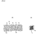
- Fig. 3 shows the radome 2 using a foamed material 8 as the matching layer 5.
- the radome 2 having the structure shown in Fig. 3 can be manufactured by carious methods.
- One is a method by which the skin layer 4 and the matching layer 5 made of the foamed material 8 are molded separately into a dome shape as shown in Fig. 1 first and then these layers are bonded together.
- the fabrication sequence can be simpler because one skin layer is omitted.
- Another manufacturing method is as follows. That is, the matching layer 5 made of the foamed material 8 is molded into a dome shape first and the glass fiber cloths 6 or glass fiber mats are layered on the outer surface of the matching layer 5.
- the skin layer 4 is formed by covering these layered materials with a sheet or the like and impregnating these layered materials with resin by pressure impregnation or vacuum impregnation.
- Still another manufacturing method is as follows. That is, a prepreg prepared by impregnating the glass fiber cloths 6 or glass fiber mats 7 with resin is placed on a dome-shaped concave molding die and the foamed material 8 formed in a dome shape is placed on the prepreg. Then, the skin layer and the matching layer are formed by impregnating the foamed material 8 and the prepreg with resin by allowing the resin to cure with heating by autoclave molding.
- the skin layer 4 can be formed by layering more than one type of fiber materials. This structure will be described using Fig. 4 .
- a layer obtained by overlapping the glass fiber cloths 6 on an organic reinforcement fibers 9 (hereinafter, referred to as the olefin fiber cloth 9), such as super-high-molecular olefin fibers, and by impregnating these overlapped cloths with the resin 7 is used as the skin layer 4.
- the olefin fiber cloth 9 the one having a lower permittivity than the glass fiber cloths 6 and making a radio wave transmittivity of the radome 2 satisfactory can be chosen.
- the skin layer 4 is made of the fiber materials layered as described above and has a specific permittivity ⁇ r of 1 or higher.
- a specific permittivity in vacuum (a specific permittivity in air is substantially the same) is 1 and reflection of radio waves occurs at the interface between the skin layer 4 and an air layer.
- the radome 2 of a canape structure is provided with the matching layer 5 to suppress such reflection on the skin layer 4.
- a technique of using a material having a permittivity of the 1/2 square of a specific permittivity of the radome itself is adopted for the matching layer (the core material sandwiched between the two skin materials) in the radome of a sandwich structure in the related art.
- a foam ratio in the foamed material is changed, a different material is mixed with the foamed material, or pores or a groove is provided to the matching layer.
- materials usable as the matching layer are limited.
- the radome of a canape structure of the invention solves this problem.
- the matching layer 5 even in a case where a material of the matching layer 5 is determined (a specific permittivity of the matching layer is also determined) to meet the demands of a cost reduction and higher manufacturability, it becomes possible to suppress reflection on the radome by providing the matching layer 5 to the skin layer 4 on the radome interior side and setting a thickness of the matching layer 5 to a predetermined thickness according to a specific permittivity thereof and other conditions, such as a communication frequency.
- the matching layer 5 can be formed by impregnating a core material with resin and allowing the resin to cure.
- the core material 10 having a resin impregnating property as shown in Fig. 5A can be used as the core material.
- the core material 10 having a resin impregnating property is a non-woven fabric combined material of a structure in which cell structures 12 are placed within a non-woven fabric 11 made of organic fibers, such as polyethylene terephthalate, so as to have clearances from one another.
- Each cell structure 12 has one or more than one void 12a defined by a partition wall in the inside and has compression resistance in a thickness direction of the non-woven fabric combined material. It is preferable that the cell structure 12 is a foamed body 13 as shown in Fig. 5B .
- This foamed body is foamed polyurethane or foamed polyacrylonitrile.
- a resin portion is the partition wall and the foamed body has one or more than one independent bubble 13a as the void 12a in the inside.
- independent bubble referred to herein is a bubble inside the foamed body and also a bubble that is not continuous to the surface of the cell structure.
- the cell structure 12 can be an aggregate of the foamed bodies 13 and can be of a polygonal shape, such as a hexagonal column shape, or a circular cylindrical shape.
- the non-woven fabric combined material as the core material 10 having a resin impregnating property may be formed by embedding foamed bodies as cell structures into a nonwoven fabric or foamed bodies obtained by injecting resin containing a foaming agent into a non-woven fabric and allowing the foaming agent to make foams may be formed as the cell structure. Further, the non-woven fabric combined material may be formed by attaching the foamed bodies to the surface of a cell non-woven fabric or by sandwiching foamed bodies as the cell structures between two non-woven fabrics.
- the matching layer 5 is formed by impregnating the core material 10 having a resin impregnating property with rein.
- the foamed body as the cell structure has an independent foam(s) in the inside. Accordingly, a void not impregnated with resin is formed in the foamed body and a resin impregnated portion impregnated with resin is formed in the clearances among the respective cell structures.
- a manufacturing method of the radome 2 of a canape structure in a case where the core material 10 having a resin impregnating property shown in Fig. 5 is used as the matching layer 5 can be further simpler. More specifically, it is possible to use a manufacturing method as follows. That is, the glass fiber cloths 6 or glass fiber mats are layered on a dome-shaped concave molding die and the core material 10 having a resin impregnating property before impregnated with resin is layered thereon. Then, the radome interior side of these layered materials is covered with a sheet or the like and these layered materials are vacuum impregnated with resin, so that the skin layer 4 and the matching layer 5 are formed integrally by infusion molding.
- the skin layer 4 and the matching layer 5 can be impregnated with rein at a time, the manufacturing becomes easier.
- the skin layer 4 can be a layer obtained by layering many types of fiber materials as shown in Fig. 4 .
- the reason why the skin layer and the matching layer can be formed integrally by infusion molding is as follows. That is, because the core material having a resin impregnating property has compression resistance in the thickness direction owing to the cell structures, and moreover, because the core material having a resin impregnating property has clearances among the respective cell structures, the core material having a resin impregnating property has excellent formativness to curved surfaces and can even secure a channel for a flow of resin during molding when the matching layer is formed.
- the cell structures occupy 40 to 80% of the entire non-woven fabric combined material when viewed from the surface thereof. It is also preferable that an area of a single cell structure is 1 cm 2 or larger. It is further preferable that an interval between the respective cell structures 13 is 1 mm or larger. In addition, it is preferable that a thickness of the skin layer 4 is 1 to 4 mm, a thickness of the matching layer 5 is 2 to 20 mm, and a total thickness of the skin layer and the matching layer (a thickness of the radome of a canape structure) is 4 to 22 mm.
- Example 1 of the radome of a canape structure will be described.
- Fig. 6 is a list showing physical properties of the radome of a canape structure of Example 1.
- glass fiber cloths available from Nitto Boseki Co., Ltd. under the trade name of NEA2116 and olefin fiber cloths available from Toyobo Co., Ltd. under the trade name of Dyneema (registered trademark) are used for the skin layer 4.
- a polyester fiber non--woven fabric known as Lantor Soric (registered trademark) available from LANTOR BV is used as the core material having a resin impregnating property for the matching layer 5.
- the finished skin layer 4 is about 2-mm thick and the finished matching layer 5 is about 5-mm thick and a communication frequency is in the Ku bandwidth.
- Lantor Soric is a type of the core material having a resin impregnating property shown in Fig. 5 in which, as is described above, the skin layer 4 and the matching layer 5 are formed integrally by infusion molding by simultaneously vacuum impregnating these layers with vinyl ester resin.
- the skin layer 4 is formed of two layers of glass fiber cloths, two layers of olefin fiber cloths, and two layers of glass fiber cloths.
- the glass fiber cloth layers have excellent tensile and bending strengths but a high permittivity.
- the olefin fiber cloth layers have a tensile strength as good as that of the glass fiber cloth layers, and although a bending strength thereof is lower than that of the glass fiber cloth layers but a permittivity is low.
- Lantor Soric alone in the matching layer 5 has lower tensile and bending strengths but the strengths are increased as it is impregnated with resin and becomes more rigid owing to its thickness (about 5 mm as described above).
- Lantor Soric used for the the matching layer 5 has a permittivity of 1.95 and vinyl ester resin impregnated therein has a permittivity of 2.72.
- the matching layer 5 has a lower permittivity than the skin layer 2.
- Fig. 7 is a graph showing a transmission characteristic of the radome of a canape structure of Example 1.
- the abscissa is used for frequencies and the ordinate is used for a transmission loss.
- Values indicated by numeral 15 in the drawing are a loss caused by a radome formed of the skin layer 4 alone without the matching layer 5.
- a loss of the radome of a canape structure of the Example 1 formed of the skin layer 4 and the matching layer 5 is actual measured values indicated by numeral 16 in the drawing.
- the radio property with a smaller loss can be obtained over a broad range (10. 95 GHz to 14.5 GHz) with the radome of a canape structure and an effectiveness thereof can be therefore confirmed.
Abstract
Description
- The present invention relates to a radome of a canape structure having a canape structure formed of a skin layer and a matching layer and storing an antenna device inside.
- An antenna device that needs protection from an external environment, such as rain, wind, snow, and dust, is normally stored in a radome when put into operation. The radome protecting the antenna device is present in a propagation path of radio waves radiated from an antenna and therefore required to have a good transmitting property and a small amount of reflection.
Patent Document 1 discloses a radome of a sandwich structure in which a core material is sandwiched between two skin materials. The skin materials are made of fiber-reinforced plastic (FRP) and the core material is made of urethane. It is described that the radome ofPatent Document 1 reduces a transmittivity loss of radio waves caused by the radome by bonding a 1/4 wavelength or 3/4 wavelength-thick core material between the skin materials. -
Patent Document 2 discloses a radome chiefly mounted on aircrafts and having a streamline shape to lessen air resistance.Patent Document 2 points out a problem that when an aircraft takes a low elevation angle, an angle yielded between a communication direction of an antenna and a normal direction to the radome wall surface becomes so large that a power loss increases. According to the radome ofPatent Document 2, an antenna device formed of a multi-layer dielectric material is provided in contact with an inner wall of the radome of a sandwich structure in which a core material is sandwiched between skin materials to make the radome function as a kind of sandwich plate, so that a transmitting property to communication power is improved by cancelling out reflected waves from the radome wall. -
- Patent Document 1:
JP-A-7-142917 - Patent Document 2:
JP-A-2004-200895 - Radomes described in both of
Patent Document 1 andPatent Document 2 have a sandwich structure in which a core material is sandwiched between skin materials and thereby obtain a satisfactory transmitting property to radio waves by appropriately setting a permittivity of the skin materials and a permittivity and a thickness of the core material while maintaining a strength by the skin material. However, in a case where a radome of a sandwich structure having a spherical or streamline shape is manufactured by sandwiching the core material between the skin materials and bonding these materials together, it becomes necessary to form the core material and the two skin materials precisely. Accordingly, there is a problem that the manufacturing costs are increased and the fabrication sequence becomes complicated. Further, radio waves from an antenna have a shorter wavelength as a communication frequency of the antenna becomes higher, for example, as high as a Ku bandwidth (in the neighborhood of 12 GHz). Hence, in order to obtain a desirable transmitting property, required precision for a thickness dimension of the radome becomes stricter. This raises a problem that it becomes more difficult to manufacture a radome of a sandwich structure. - The invention is devised to solve the problems discussed above and has an obj ect to obtain a radome having, not a sandwich structure but a canape structure, which is a radome of a canape structure having a satisfactory radio property, and moreover, an excellent mechanical strength.
- A radome of a canape structure according to the invention includes a skin layer shaped like a dome using a glass fiber cloth or a glass fiber mat as reinforcement fibers and formed by impregnating the reinforcement fibers with resin, and a matching layer provided integrally with the skin layer on an inner side of the dome and made of a dielectric material having a lower permittivity than the skin layer.
- According to the invention, the radome has a canape structure formed of the skin layer shaped like a dome and the matching layer made of a dielectric material having a lower permittivity than the skin layer and provided on the inner side of the dome. Hence, the radome can be readily manufactured and a transmitting property to radio waves can be enhanced.
-
-
Fig. 1 is a cross section showing the overall configuration of an antenna device using a radome according to a first embodiment of the invention. -
Fig. 2 is a partial perspective cross section of the radome according to the first embodiment of the invention. -
Fig, 3 is a partial perspective cross section using a foamed material as a matching layer of the first embodiment. -
Fig. 4 is a partial perspective cross section of a radome using more than one type of fibers for a skin layer of the first embodiment. -
Fig. 5A is a cross section showing an entire non-woven fabric combined material as a core material having a resin impregnating property used for the matching layer of the first embodiment andFig. 5B is a partially broken perspective view of a foamed body as a single cell structure. -
Fig. 6 is a list showing physical properties of the radome according to Example 1 of the first embodiment. -
Fig. 7 is a graph showing a transmitting property of the radome according to Example 1 of the first embodiment. - A radome of a canape structure according to a first embodiment of the invention will be described on the basis of
Fig. 1 through Fig. 5 .Fig. 1 is a cross section showing the overall configuration of an antenna device using the radome according to the first embodiment of the invention. Referring toFig. 1 , theantenna device 1 includes areflector antenna 1a and a supporting anddriving structure 1b thereof and is covered entirely with aradome 2. Theantenna device 1 and theradome 2 are installed on aradome stand 3. Theantenna device 1 is configured in such a manner that thereflector antenna 1a is driven by the supporting anddriving structure 1b about an orientation axis and an elevation axis. Theradome 2 is shaped to have acanopy portion 20 of substantially a hemispherical shape and abody portion 30 of a cylindrical or conical shape so as not to mechanically interfere with thereflector antenna 1a within a movable range thereof. Hereinafter, a side of theradome 2 on which theantenna device 1 is stored is referred to as the interior side of theradome 2 and the opposite side is referred to as the exterior side of theradome 2. - The
antenna device 1, by being stored in theradome 2, is protected from an external environment, such as rain, wind, snow, and dust. However, because theradome 2 is present in a propagation path of radio waves radiated from theantenna device 1, theradome 2 is required to have a satisfactory transmitting property to radio waves and a small amount of reflection. Also, theradome 2 is required to have a mechanical strength high enough to withstand a load (wind load) and a force of impact (collision of birds or the like) from the external environment. -
Fig. 2 is an enlarged perspective cross section of a portion A of theradome 2 ofFig. 1 . Referring toFig. 2 , theradome 2 has a structure in which askin layer 4 and amatching layer 5 are overlapped each other. Herein, assume that theskin layer 4 is the substrate of theradome 2, then, because thematching layer 5 is provided on one surface of theskin layer 4 as the substrate, this structure of theradome 2 is distinguished from a sandwich structure and referred to as a canape structure. This configuration is different from that of the radome of a sandwich structure in the related art. The radome of a sandwich structure is further provided with a skin layer of substantially the same configuration as theskin layer 4 placed on thematching layer 5 on the interior side of theradome 2 in addition to the configuration ofFig. 2 . This structure is referred to as a sandwich structure to mean that a core layer is sandwiched between two skin layers. - The phrase, "a radome of a canape structure", includes all radomes having the structure of
Fig. 2 in a finished state after the manufacturing regardless of whether which one of theskin layer 4 and thematching layer 5 is formed first or whether theskin layer 4 and thematching layer 5 are formed simultaneously. In addition, because a surface of the matchinglayer 5 on the interior side of theradome 2 is exposed to air, a surface layer may be formed by applying coating or laminating a thin film thereon for the purpose of providing protection. This surface layer, however, is additional and a radome structure in which the surface layer is formed on thematching layer 5 is not referred to as a sandwich structure and included in radomes of a canape structure. - The
skin layer 4 is provided to thematching layer 5 on the exterior side of theradome 2. Theskin layer 4 is formed of high-strengthglass fiber cloths 6 as reinforcement fibers impregnated withresin 7. Theglass fiber cloths 6 used for theskin layer 4 have a high mechanical strength and are therefore suitable as a material forming theskin layer 4 in contact with an external environment of theradome 2. It should be noted, however, that theglass fiber cloths 6 have a high permittivity and a radio wave transmittivity decreases generally when a content of theglass fiber cloths 6 is increased. It is preferable that a content ratio of glass fibers in the skin layer is 30 to 60 wt%. Further, normal glass fibers have an E glass composition and a permittivity (1 MHz) thereof is 6.6. It is preferable for the radome of the invention that a permittivity (1 MHz) of a glass composite of the glass fiber cloths is 6 or below, and more preferably, 5 or below. An example of glass fibers having such a glass composition is commercially available from Nitto Boseki Co., Ltd., under the trade name of NE GLASS. A permittivity (1 MHz) of this glass composition is 4.6.Fig. 2 shows an example provided with three layers of theglass fiber cloths 6. It should be appreciated, however, that the number of layers is not limited to three and theglass fiber cloths 6 andresin 7 impregnated therein do not necessarily form distinct layers as is shown in the drawing. Further, theglass fiber cloths 6 may be replaced with a glass fiber mat and one mat or plural layered mats can be used. Meanwhile, a foamed material, such as a urethane material having a low permittivity or a core material having a resin impregnating property is used as thematching layer 5.Fig. 3 shows theradome 2 using a foamed material 8 as thematching layer 5. - The
radome 2 having the structure shown inFig. 3 can be manufactured by carious methods. One is a method by which theskin layer 4 and thematching layer 5 made of the foamed material 8 are molded separately into a dome shape as shown inFig. 1 first and then these layers are bonded together. In this case, in comparison with a radome of a sandwich structure in the related art in which a core material is sandwiched between two skin materials and bonded together, the fabrication sequence can be simpler because one skin layer is omitted. Another manufacturing method is as follows. That is, thematching layer 5 made of the foamed material 8 is molded into a dome shape first and theglass fiber cloths 6 or glass fiber mats are layered on the outer surface of thematching layer 5. Then, theskin layer 4 is formed by covering these layered materials with a sheet or the like and impregnating these layered materials with resin by pressure impregnation or vacuum impregnation. Still another manufacturing method is as follows. That is, a prepreg prepared by impregnating theglass fiber cloths 6 orglass fiber mats 7 with resin is placed on a dome-shaped concave molding die and the foamed material 8 formed in a dome shape is placed on the prepreg. Then, the skin layer and the matching layer are formed by impregnating the foamed material 8 and the prepreg with resin by allowing the resin to cure with heating by autoclave molding. - The
skin layer 4 can be formed by layering more than one type of fiber materials. This structure will be described usingFig. 4 . Referring toFig. 4 , a layer obtained by overlapping theglass fiber cloths 6 on an organic reinforcement fibers 9 (hereinafter, referred to as the olefin fiber cloth 9), such as super-high-molecular olefin fibers, and by impregnating these overlapped cloths with theresin 7 is used as theskin layer 4. As theolefin fiber cloth 9, the one having a lower permittivity than theglass fiber cloths 6 and making a radio wave transmittivity of theradome 2 satisfactory can be chosen. - Assume that a radome is formed of the
skin layer 4 alone without thematching layer 5, then theskin layer 4 is made of the fiber materials layered as described above and has a specific permittivity εr of 1 or higher. Meanwhile, a specific permittivity in vacuum (a specific permittivity in air is substantially the same) is 1 and reflection of radio waves occurs at the interface between theskin layer 4 and an air layer. Theradome 2 of a canape structure is provided with thematching layer 5 to suppress such reflection on theskin layer 4. In order to suppress reflection on the radome, a technique of using a material having a permittivity of the 1/2 square of a specific permittivity of the radome itself is adopted for the matching layer (the core material sandwiched between the two skin materials) in the radome of a sandwich structure in the related art. In this case, in order to obtain a desirable specific permittivity, a foam ratio in the foamed material is changed, a different material is mixed with the foamed material, or pores or a groove is provided to the matching layer. Hence, from the viewpoints of weight, mechanical strength, manufacturability, and the cost, materials usable as the matching layer are limited. The radome of a canape structure of the invention solves this problem. For example, even in a case where a material of thematching layer 5 is determined (a specific permittivity of the matching layer is also determined) to meet the demands of a cost reduction and higher manufacturability, it becomes possible to suppress reflection on the radome by providing thematching layer 5 to theskin layer 4 on the radome interior side and setting a thickness of thematching layer 5 to a predetermined thickness according to a specific permittivity thereof and other conditions, such as a communication frequency. - The
matching layer 5 can be formed by impregnating a core material with resin and allowing the resin to cure. Thecore material 10 having a resin impregnating property as shown inFig. 5A can be used as the core material. Thecore material 10 having a resin impregnating property is a non-woven fabric combined material of a structure in whichcell structures 12 are placed within anon-woven fabric 11 made of organic fibers, such as polyethylene terephthalate, so as to have clearances from one another. Eachcell structure 12 has one or more than one void 12a defined by a partition wall in the inside and has compression resistance in a thickness direction of the non-woven fabric combined material. It is preferable that thecell structure 12 is a foamedbody 13 as shown inFig. 5B . This foamed body is foamed polyurethane or foamed polyacrylonitrile. A resin portion is the partition wall and the foamed body has one or more than oneindependent bubble 13a as the void 12a in the inside. The term, "independent bubble", referred to herein is a bubble inside the foamed body and also a bubble that is not continuous to the surface of the cell structure. Thecell structure 12 can be an aggregate of the foamedbodies 13 and can be of a polygonal shape, such as a hexagonal column shape, or a circular cylindrical shape. - The non-woven fabric combined material as the
core material 10 having a resin impregnating property may be formed by embedding foamed bodies as cell structures into a nonwoven fabric or foamed bodies obtained by injecting resin containing a foaming agent into a non-woven fabric and allowing the foaming agent to make foams may be formed as the cell structure. Further, the non-woven fabric combined material may be formed by attaching the foamed bodies to the surface of a cell non-woven fabric or by sandwiching foamed bodies as the cell structures between two non-woven fabrics. Thematching layer 5 is formed by impregnating thecore material 10 having a resin impregnating property with rein. The foamed body as the cell structure has an independent foam(s) in the inside. Accordingly, a void not impregnated with resin is formed in the foamed body and a resin impregnated portion impregnated with resin is formed in the clearances among the respective cell structures. - A manufacturing method of the
radome 2 of a canape structure in a case where thecore material 10 having a resin impregnating property shown inFig. 5 is used as thematching layer 5 can be further simpler. More specifically, it is possible to use a manufacturing method as follows. That is, theglass fiber cloths 6 or glass fiber mats are layered on a dome-shaped concave molding die and thecore material 10 having a resin impregnating property before impregnated with resin is layered thereon. Then, the radome interior side of these layered materials is covered with a sheet or the like and these layered materials are vacuum impregnated with resin, so that theskin layer 4 and thematching layer 5 are formed integrally by infusion molding. In this case, because theskin layer 4 and thematching layer 5 can be impregnated with rein at a time, the manufacturing becomes easier. Theskin layer 4 can be a layer obtained by layering many types of fiber materials as shown inFig. 4 . The reason why the skin layer and the matching layer can be formed integrally by infusion molding is as follows. That is, because the core material having a resin impregnating property has compression resistance in the thickness direction owing to the cell structures, and moreover, because the core material having a resin impregnating property has clearances among the respective cell structures, the core material having a resin impregnating property has excellent formativness to curved surfaces and can even secure a channel for a flow of resin during molding when the matching layer is formed. In order to let this characteristic be exerted effectively, it is preferable that the cell structures occupy 40 to 80% of the entire non-woven fabric combined material when viewed from the surface thereof. It is also preferable that an area of a single cell structure is 1 cm2 or larger. It is further preferable that an interval between therespective cell structures 13 is 1 mm or larger. In addition, it is preferable that a thickness of theskin layer 4 is 1 to 4 mm, a thickness of thematching layer 5 is 2 to 20 mm, and a total thickness of the skin layer and the matching layer (a thickness of the radome of a canape structure) is 4 to 22 mm. - Example 1 of the radome of a canape structure will be described.
Fig. 6 is a list showing physical properties of the radome of a canape structure of Example 1. In Example 1, glass fiber cloths available from Nitto Boseki Co., Ltd. under the trade name of NEA2116 and olefin fiber cloths available from Toyobo Co., Ltd. under the trade name of Dyneema (registered trademark) are used for theskin layer 4. Also, a polyester fiber non--woven fabric known as Lantor Soric (registered trademark) available from LANTOR BV is used as the core material having a resin impregnating property for thematching layer 5. Regarding the thickness of the radome, thefinished skin layer 4 is about 2-mm thick and thefinished matching layer 5 is about 5-mm thick and a communication frequency is in the Ku bandwidth. Lantor Soric is a type of the core material having a resin impregnating property shown inFig. 5 in which, as is described above, theskin layer 4 and thematching layer 5 are formed integrally by infusion molding by simultaneously vacuum impregnating these layers with vinyl ester resin. - The
skin layer 4 is formed of two layers of glass fiber cloths, two layers of olefin fiber cloths, and two layers of glass fiber cloths. The glass fiber cloth layers have excellent tensile and bending strengths but a high permittivity. Meanwhile, the olefin fiber cloth layers have a tensile strength as good as that of the glass fiber cloth layers, and although a bending strength thereof is lower than that of the glass fiber cloth layers but a permittivity is low. Lantor Soric alone in thematching layer 5 has lower tensile and bending strengths but the strengths are increased as it is impregnated with resin and becomes more rigid owing to its thickness (about 5 mm as described above). Lantor Soric used for the thematching layer 5 has a permittivity of 1.95 and vinyl ester resin impregnated therein has a permittivity of 2.72. Hence, thematching layer 5 has a lower permittivity than theskin layer 2. -
Fig. 7 is a graph showing a transmission characteristic of the radome of a canape structure of Example 1. The abscissa is used for frequencies and the ordinate is used for a transmission loss. Values indicated by numeral 15 in the drawing are a loss caused by a radome formed of theskin layer 4 alone without thematching layer 5. A loss of the radome of a canape structure of the Example 1 formed of theskin layer 4 and thematching layer 5 is actual measured values indicated by numeral 16 in the drawing. Hence, it can be understood that the radio property with a smaller loss can be obtained over a broad range (10. 95 GHz to 14.5 GHz) with the radome of a canape structure and an effectiveness thereof can be therefore confirmed. -
- 1:
- antenna device
- 1a:
- reflector antenna
- 1b:
- supporting and driving structure
- 2:
- radome
- 3:
- radome stand
- 4:
- skin layer
- 5:
- matching layer
- 6:
- glass fiber cloth
- 7:
- resin
- 8:
- foamed material
- 9:
- olefin fiber cloth
- 10:
- non-woven fabric combined material (core material having a resin impregnating property)
- 11:
- non-woven fabric
- 12:
- cell structure
- 12a:
- void
- 13:
- foamed body
- 13a:
- independent bubble
- 20:
- radome canopy portion
- 30:
- radome body portion
Claims (5)
- A radome of a canape structure characterized by comprising:a skin layer shaped like a dome using a glass fiber cloth or a glass fiber mat as reinforcement fibers and formed by impregnating the reinforcement fibers with resin; anda matching layer provided integrally with the skin layer on an inner side of the dome and made of a dielectric material having a lower permittivity than the skin layer.
- The radome of a canape structure according to claim 1, characterized in that the matching layer is a foamed material.
- The radome of a canape structure according to claim 1, characterized in that the skin layer and the matching layer are formed integrally by impregnating the skin layer and the matching layer with the resin.
- The radome of a canape structure according to claim 1 or 3, characterized in that the matching layer has, as a core material, a non-woven fabric combined material in which a plurality of cell structures each having compression resistance in a thickness direction are placed within or on a surface of the non-woven fabric so as to have clearances from one another and the resin is impregnated into the clearances.
- The radome of a canape structure according to any one of claims 1 through 4, characterized in that the skin layer includes layered olefin fiber cloths.
Applications Claiming Priority (2)
| Application Number | Priority Date | Filing Date | Title |
|---|---|---|---|
| JP2009237299A JP5084808B2 (en) | 2009-10-14 | 2009-10-14 | Canapé radome |
| PCT/JP2010/067837 WO2011046100A1 (en) | 2009-10-14 | 2010-10-12 | Radome having canape structure |
Publications (3)
| Publication Number | Publication Date |
|---|---|
| EP2472671A1 true EP2472671A1 (en) | 2012-07-04 |
| EP2472671A4 EP2472671A4 (en) | 2013-06-12 |
| EP2472671B1 EP2472671B1 (en) | 2015-09-30 |
Family
ID=43876150
Family Applications (1)
| Application Number | Title | Priority Date | Filing Date |
|---|---|---|---|
| EP10823368.5A Not-in-force EP2472671B1 (en) | 2009-10-14 | 2010-10-12 | Radome for an antenna |
Country Status (4)
| Country | Link |
|---|---|
| US (1) | US8760359B2 (en) |
| EP (1) | EP2472671B1 (en) |
| JP (1) | JP5084808B2 (en) |
| WO (1) | WO2011046100A1 (en) |
Cited By (154)
| Publication number | Priority date | Publication date | Assignee | Title |
|---|---|---|---|---|
| EP2884582A4 (en) * | 2012-08-07 | 2016-02-10 | Intellian Technologies Inc | Satellite antenna housing |
| US9544006B2 (en) | 2014-11-20 | 2017-01-10 | At&T Intellectual Property I, L.P. | Transmission device with mode division multiplexing and methods for use therewith |
| US9577306B2 (en) | 2014-10-21 | 2017-02-21 | At&T Intellectual Property I, L.P. | Guided-wave transmission device and methods for use therewith |
| US9596001B2 (en) | 2014-10-21 | 2017-03-14 | At&T Intellectual Property I, L.P. | Apparatus for providing communication services and methods thereof |
| US9608692B2 (en) | 2015-06-11 | 2017-03-28 | At&T Intellectual Property I, L.P. | Repeater and methods for use therewith |
| US9608740B2 (en) | 2015-07-15 | 2017-03-28 | At&T Intellectual Property I, L.P. | Method and apparatus for launching a wave mode that mitigates interference |
| US9615269B2 (en) | 2014-10-02 | 2017-04-04 | At&T Intellectual Property I, L.P. | Method and apparatus that provides fault tolerance in a communication network |
| US9627768B2 (en) | 2014-10-21 | 2017-04-18 | At&T Intellectual Property I, L.P. | Guided-wave transmission device with non-fundamental mode propagation and methods for use therewith |
| US9628116B2 (en) | 2015-07-14 | 2017-04-18 | At&T Intellectual Property I, L.P. | Apparatus and methods for transmitting wireless signals |
| US9640850B2 (en) | 2015-06-25 | 2017-05-02 | At&T Intellectual Property I, L.P. | Methods and apparatus for inducing a non-fundamental wave mode on a transmission medium |
| US9654173B2 (en) | 2014-11-20 | 2017-05-16 | At&T Intellectual Property I, L.P. | Apparatus for powering a communication device and methods thereof |
| US9653770B2 (en) | 2014-10-21 | 2017-05-16 | At&T Intellectual Property I, L.P. | Guided wave coupler, coupling module and methods for use therewith |
| US9661505B2 (en) | 2013-11-06 | 2017-05-23 | At&T Intellectual Property I, L.P. | Surface-wave communications and methods thereof |
| US9667317B2 (en) | 2015-06-15 | 2017-05-30 | At&T Intellectual Property I, L.P. | Method and apparatus for providing security using network traffic adjustments |
| US9685992B2 (en) | 2014-10-03 | 2017-06-20 | At&T Intellectual Property I, L.P. | Circuit panel network and methods thereof |
| US9692101B2 (en) | 2014-08-26 | 2017-06-27 | At&T Intellectual Property I, L.P. | Guided wave couplers for coupling electromagnetic waves between a waveguide surface and a surface of a wire |
| US9699785B2 (en) | 2012-12-05 | 2017-07-04 | At&T Intellectual Property I, L.P. | Backhaul link for distributed antenna system |
| US9705561B2 (en) | 2015-04-24 | 2017-07-11 | At&T Intellectual Property I, L.P. | Directional coupling device and methods for use therewith |
| US9705610B2 (en) | 2014-10-21 | 2017-07-11 | At&T Intellectual Property I, L.P. | Transmission device with impairment compensation and methods for use therewith |
| US9712350B2 (en) | 2014-11-20 | 2017-07-18 | At&T Intellectual Property I, L.P. | Transmission device with channel equalization and control and methods for use therewith |
| US9722318B2 (en) | 2015-07-14 | 2017-08-01 | At&T Intellectual Property I, L.P. | Method and apparatus for coupling an antenna to a device |
| US9729197B2 (en) | 2015-10-01 | 2017-08-08 | At&T Intellectual Property I, L.P. | Method and apparatus for communicating network management traffic over a network |
| US9735833B2 (en) | 2015-07-31 | 2017-08-15 | At&T Intellectual Property I, L.P. | Method and apparatus for communications management in a neighborhood network |
| US9742462B2 (en) | 2014-12-04 | 2017-08-22 | At&T Intellectual Property I, L.P. | Transmission medium and communication interfaces and methods for use therewith |
| US9749053B2 (en) | 2015-07-23 | 2017-08-29 | At&T Intellectual Property I, L.P. | Node device, repeater and methods for use therewith |
| US9748626B2 (en) | 2015-05-14 | 2017-08-29 | At&T Intellectual Property I, L.P. | Plurality of cables having different cross-sectional shapes which are bundled together to form a transmission medium |
| US9749013B2 (en) | 2015-03-17 | 2017-08-29 | At&T Intellectual Property I, L.P. | Method and apparatus for reducing attenuation of electromagnetic waves guided by a transmission medium |
| US9762289B2 (en) | 2014-10-14 | 2017-09-12 | At&T Intellectual Property I, L.P. | Method and apparatus for transmitting or receiving signals in a transportation system |
| US9769020B2 (en) | 2014-10-21 | 2017-09-19 | At&T Intellectual Property I, L.P. | Method and apparatus for responding to events affecting communications in a communication network |
| US9768833B2 (en) | 2014-09-15 | 2017-09-19 | At&T Intellectual Property I, L.P. | Method and apparatus for sensing a condition in a transmission medium of electromagnetic waves |
| US9769128B2 (en) | 2015-09-28 | 2017-09-19 | At&T Intellectual Property I, L.P. | Method and apparatus for encryption of communications over a network |
| US9780834B2 (en) | 2014-10-21 | 2017-10-03 | At&T Intellectual Property I, L.P. | Method and apparatus for transmitting electromagnetic waves |
| US9787412B2 (en) | 2015-06-25 | 2017-10-10 | At&T Intellectual Property I, L.P. | Methods and apparatus for inducing a fundamental wave mode on a transmission medium |
| US9793951B2 (en) | 2015-07-15 | 2017-10-17 | At&T Intellectual Property I, L.P. | Method and apparatus for launching a wave mode that mitigates interference |
| US9794003B2 (en) | 2013-12-10 | 2017-10-17 | At&T Intellectual Property I, L.P. | Quasi-optical coupler |
| US9793955B2 (en) | 2015-04-24 | 2017-10-17 | At&T Intellectual Property I, Lp | Passive electrical coupling device and methods for use therewith |
| US9793954B2 (en) | 2015-04-28 | 2017-10-17 | At&T Intellectual Property I, L.P. | Magnetic coupling device and methods for use therewith |
| US9800327B2 (en) | 2014-11-20 | 2017-10-24 | At&T Intellectual Property I, L.P. | Apparatus for controlling operations of a communication device and methods thereof |
| US9820146B2 (en) | 2015-06-12 | 2017-11-14 | At&T Intellectual Property I, L.P. | Method and apparatus for authentication and identity management of communicating devices |
| US9838078B2 (en) | 2015-07-31 | 2017-12-05 | At&T Intellectual Property I, L.P. | Method and apparatus for exchanging communication signals |
| US9838896B1 (en) | 2016-12-09 | 2017-12-05 | At&T Intellectual Property I, L.P. | Method and apparatus for assessing network coverage |
| US9836957B2 (en) | 2015-07-14 | 2017-12-05 | At&T Intellectual Property I, L.P. | Method and apparatus for communicating with premises equipment |
| US9847566B2 (en) | 2015-07-14 | 2017-12-19 | At&T Intellectual Property I, L.P. | Method and apparatus for adjusting a field of a signal to mitigate interference |
| US9847850B2 (en) | 2014-10-14 | 2017-12-19 | At&T Intellectual Property I, L.P. | Method and apparatus for adjusting a mode of communication in a communication network |
| US9853342B2 (en) | 2015-07-14 | 2017-12-26 | At&T Intellectual Property I, L.P. | Dielectric transmission medium connector and methods for use therewith |
| US9860075B1 (en) | 2016-08-26 | 2018-01-02 | At&T Intellectual Property I, L.P. | Method and communication node for broadband distribution |
| US9866276B2 (en) | 2014-10-10 | 2018-01-09 | At&T Intellectual Property I, L.P. | Method and apparatus for arranging communication sessions in a communication system |
| US9866309B2 (en) | 2015-06-03 | 2018-01-09 | At&T Intellectual Property I, Lp | Host node device and methods for use therewith |
| US9865911B2 (en) | 2015-06-25 | 2018-01-09 | At&T Intellectual Property I, L.P. | Waveguide system for slot radiating first electromagnetic waves that are combined into a non-fundamental wave mode second electromagnetic wave on a transmission medium |
| US9871282B2 (en) | 2015-05-14 | 2018-01-16 | At&T Intellectual Property I, L.P. | At least one transmission medium having a dielectric surface that is covered at least in part by a second dielectric |
| US9871283B2 (en) | 2015-07-23 | 2018-01-16 | At&T Intellectual Property I, Lp | Transmission medium having a dielectric core comprised of plural members connected by a ball and socket configuration |
| US9876570B2 (en) | 2015-02-20 | 2018-01-23 | At&T Intellectual Property I, Lp | Guided-wave transmission device with non-fundamental mode propagation and methods for use therewith |
| US9876605B1 (en) | 2016-10-21 | 2018-01-23 | At&T Intellectual Property I, L.P. | Launcher and coupling system to support desired guided wave mode |
| US9876264B2 (en) | 2015-10-02 | 2018-01-23 | At&T Intellectual Property I, Lp | Communication system, guided wave switch and methods for use therewith |
| US9882277B2 (en) | 2015-10-02 | 2018-01-30 | At&T Intellectual Property I, Lp | Communication device and antenna assembly with actuated gimbal mount |
| US9882257B2 (en) | 2015-07-14 | 2018-01-30 | At&T Intellectual Property I, L.P. | Method and apparatus for launching a wave mode that mitigates interference |
| US9887447B2 (en) | 2015-05-14 | 2018-02-06 | At&T Intellectual Property I, L.P. | Transmission medium having multiple cores and methods for use therewith |
| US9893795B1 (en) | 2016-12-07 | 2018-02-13 | At&T Intellectual Property I, Lp | Method and repeater for broadband distribution |
| US9906269B2 (en) | 2014-09-17 | 2018-02-27 | At&T Intellectual Property I, L.P. | Monitoring and mitigating conditions in a communication network |
| US9904535B2 (en) | 2015-09-14 | 2018-02-27 | At&T Intellectual Property I, L.P. | Method and apparatus for distributing software |
| US9912027B2 (en) | 2015-07-23 | 2018-03-06 | At&T Intellectual Property I, L.P. | Method and apparatus for exchanging communication signals |
| US9912382B2 (en) | 2015-06-03 | 2018-03-06 | At&T Intellectual Property I, Lp | Network termination and methods for use therewith |
| US9912419B1 (en) | 2016-08-24 | 2018-03-06 | At&T Intellectual Property I, L.P. | Method and apparatus for managing a fault in a distributed antenna system |
| US9911020B1 (en) | 2016-12-08 | 2018-03-06 | At&T Intellectual Property I, L.P. | Method and apparatus for tracking via a radio frequency identification device |
| US9913139B2 (en) | 2015-06-09 | 2018-03-06 | At&T Intellectual Property I, L.P. | Signal fingerprinting for authentication of communicating devices |
| US9917341B2 (en) | 2015-05-27 | 2018-03-13 | At&T Intellectual Property I, L.P. | Apparatus and method for launching electromagnetic waves and for modifying radial dimensions of the propagating electromagnetic waves |
| US9930668B2 (en) | 2013-05-31 | 2018-03-27 | At&T Intellectual Property I, L.P. | Remote distributed antenna system |
| US9927517B1 (en) | 2016-12-06 | 2018-03-27 | At&T Intellectual Property I, L.P. | Apparatus and methods for sensing rainfall |
| US9948333B2 (en) | 2015-07-23 | 2018-04-17 | At&T Intellectual Property I, L.P. | Method and apparatus for wireless communications to mitigate interference |
| US9948354B2 (en) | 2015-04-28 | 2018-04-17 | At&T Intellectual Property I, L.P. | Magnetic coupling device with reflective plate and methods for use therewith |
| US9954287B2 (en) | 2014-11-20 | 2018-04-24 | At&T Intellectual Property I, L.P. | Apparatus for converting wireless signals and electromagnetic waves and methods thereof |
| US9967173B2 (en) | 2015-07-31 | 2018-05-08 | At&T Intellectual Property I, L.P. | Method and apparatus for authentication and identity management of communicating devices |
| US9973940B1 (en) | 2017-02-27 | 2018-05-15 | At&T Intellectual Property I, L.P. | Apparatus and methods for dynamic impedance matching of a guided wave launcher |
| US9991580B2 (en) | 2016-10-21 | 2018-06-05 | At&T Intellectual Property I, L.P. | Launcher and coupling system for guided wave mode cancellation |
| US9999038B2 (en) | 2013-05-31 | 2018-06-12 | At&T Intellectual Property I, L.P. | Remote distributed antenna system |
| US9998870B1 (en) | 2016-12-08 | 2018-06-12 | At&T Intellectual Property I, L.P. | Method and apparatus for proximity sensing |
| US9997819B2 (en) | 2015-06-09 | 2018-06-12 | At&T Intellectual Property I, L.P. | Transmission medium and method for facilitating propagation of electromagnetic waves via a core |
| US10009063B2 (en) | 2015-09-16 | 2018-06-26 | At&T Intellectual Property I, L.P. | Method and apparatus for use with a radio distributed antenna system having an out-of-band reference signal |
| US10009065B2 (en) | 2012-12-05 | 2018-06-26 | At&T Intellectual Property I, L.P. | Backhaul link for distributed antenna system |
| US10009901B2 (en) | 2015-09-16 | 2018-06-26 | At&T Intellectual Property I, L.P. | Method, apparatus, and computer-readable storage medium for managing utilization of wireless resources between base stations |
| US10009067B2 (en) | 2014-12-04 | 2018-06-26 | At&T Intellectual Property I, L.P. | Method and apparatus for configuring a communication interface |
| US10020587B2 (en) | 2015-07-31 | 2018-07-10 | At&T Intellectual Property I, L.P. | Radial antenna and methods for use therewith |
| US10020844B2 (en) | 2016-12-06 | 2018-07-10 | T&T Intellectual Property I, L.P. | Method and apparatus for broadcast communication via guided waves |
| US10027397B2 (en) | 2016-12-07 | 2018-07-17 | At&T Intellectual Property I, L.P. | Distributed antenna system and methods for use therewith |
| US10033108B2 (en) | 2015-07-14 | 2018-07-24 | At&T Intellectual Property I, L.P. | Apparatus and methods for generating an electromagnetic wave having a wave mode that mitigates interference |
| US10033107B2 (en) | 2015-07-14 | 2018-07-24 | At&T Intellectual Property I, L.P. | Method and apparatus for coupling an antenna to a device |
| US10044409B2 (en) | 2015-07-14 | 2018-08-07 | At&T Intellectual Property I, L.P. | Transmission medium and methods for use therewith |
| US10069535B2 (en) | 2016-12-08 | 2018-09-04 | At&T Intellectual Property I, L.P. | Apparatus and methods for launching electromagnetic waves having a certain electric field structure |
| US10079661B2 (en) | 2015-09-16 | 2018-09-18 | At&T Intellectual Property I, L.P. | Method and apparatus for use with a radio distributed antenna system having a clock reference |
| US10090594B2 (en) | 2016-11-23 | 2018-10-02 | At&T Intellectual Property I, L.P. | Antenna system having structural configurations for assembly |
| US10090606B2 (en) | 2015-07-15 | 2018-10-02 | At&T Intellectual Property I, L.P. | Antenna system with dielectric array and methods for use therewith |
| US10103801B2 (en) | 2015-06-03 | 2018-10-16 | At&T Intellectual Property I, L.P. | Host node device and methods for use therewith |
| US10103422B2 (en) | 2016-12-08 | 2018-10-16 | At&T Intellectual Property I, L.P. | Method and apparatus for mounting network devices |
| US10135147B2 (en) | 2016-10-18 | 2018-11-20 | At&T Intellectual Property I, L.P. | Apparatus and methods for launching guided waves via an antenna |
| US10135146B2 (en) | 2016-10-18 | 2018-11-20 | At&T Intellectual Property I, L.P. | Apparatus and methods for launching guided waves via circuits |
| US10135145B2 (en) | 2016-12-06 | 2018-11-20 | At&T Intellectual Property I, L.P. | Apparatus and methods for generating an electromagnetic wave along a transmission medium |
| US10136434B2 (en) | 2015-09-16 | 2018-11-20 | At&T Intellectual Property I, L.P. | Method and apparatus for use with a radio distributed antenna system having an ultra-wideband control channel |
| US10142086B2 (en) | 2015-06-11 | 2018-11-27 | At&T Intellectual Property I, L.P. | Repeater and methods for use therewith |
| US10139820B2 (en) | 2016-12-07 | 2018-11-27 | At&T Intellectual Property I, L.P. | Method and apparatus for deploying equipment of a communication system |
| US10148016B2 (en) | 2015-07-14 | 2018-12-04 | At&T Intellectual Property I, L.P. | Apparatus and methods for communicating utilizing an antenna array |
| US10144036B2 (en) | 2015-01-30 | 2018-12-04 | At&T Intellectual Property I, L.P. | Method and apparatus for mitigating interference affecting a propagation of electromagnetic waves guided by a transmission medium |
| US10170840B2 (en) | 2015-07-14 | 2019-01-01 | At&T Intellectual Property I, L.P. | Apparatus and methods for sending or receiving electromagnetic signals |
| US10168695B2 (en) | 2016-12-07 | 2019-01-01 | At&T Intellectual Property I, L.P. | Method and apparatus for controlling an unmanned aircraft |
| US10178445B2 (en) | 2016-11-23 | 2019-01-08 | At&T Intellectual Property I, L.P. | Methods, devices, and systems for load balancing between a plurality of waveguides |
| US10205655B2 (en) | 2015-07-14 | 2019-02-12 | At&T Intellectual Property I, L.P. | Apparatus and methods for communicating utilizing an antenna array and multiple communication paths |
| US10225025B2 (en) | 2016-11-03 | 2019-03-05 | At&T Intellectual Property I, L.P. | Method and apparatus for detecting a fault in a communication system |
| US10224634B2 (en) | 2016-11-03 | 2019-03-05 | At&T Intellectual Property I, L.P. | Methods and apparatus for adjusting an operational characteristic of an antenna |
| US10243270B2 (en) | 2016-12-07 | 2019-03-26 | At&T Intellectual Property I, L.P. | Beam adaptive multi-feed dielectric antenna system and methods for use therewith |
| US10264586B2 (en) | 2016-12-09 | 2019-04-16 | At&T Mobility Ii Llc | Cloud-based packet controller and methods for use therewith |
| US10291311B2 (en) | 2016-09-09 | 2019-05-14 | At&T Intellectual Property I, L.P. | Method and apparatus for mitigating a fault in a distributed antenna system |
| US10291334B2 (en) | 2016-11-03 | 2019-05-14 | At&T Intellectual Property I, L.P. | System for detecting a fault in a communication system |
| US10298293B2 (en) | 2017-03-13 | 2019-05-21 | At&T Intellectual Property I, L.P. | Apparatus of communication utilizing wireless network devices |
| US10305190B2 (en) | 2016-12-01 | 2019-05-28 | At&T Intellectual Property I, L.P. | Reflecting dielectric antenna system and methods for use therewith |
| US10312567B2 (en) | 2016-10-26 | 2019-06-04 | At&T Intellectual Property I, L.P. | Launcher with planar strip antenna and methods for use therewith |
| US10320586B2 (en) | 2015-07-14 | 2019-06-11 | At&T Intellectual Property I, L.P. | Apparatus and methods for generating non-interfering electromagnetic waves on an insulated transmission medium |
| US10326689B2 (en) | 2016-12-08 | 2019-06-18 | At&T Intellectual Property I, L.P. | Method and system for providing alternative communication paths |
| US10326494B2 (en) | 2016-12-06 | 2019-06-18 | At&T Intellectual Property I, L.P. | Apparatus for measurement de-embedding and methods for use therewith |
| US10340600B2 (en) | 2016-10-18 | 2019-07-02 | At&T Intellectual Property I, L.P. | Apparatus and methods for launching guided waves via plural waveguide systems |
| US10340573B2 (en) | 2016-10-26 | 2019-07-02 | At&T Intellectual Property I, L.P. | Launcher with cylindrical coupling device and methods for use therewith |
| US10340601B2 (en) | 2016-11-23 | 2019-07-02 | At&T Intellectual Property I, L.P. | Multi-antenna system and methods for use therewith |
| US10341142B2 (en) | 2015-07-14 | 2019-07-02 | At&T Intellectual Property I, L.P. | Apparatus and methods for generating non-interfering electromagnetic waves on an uninsulated conductor |
| US10340603B2 (en) | 2016-11-23 | 2019-07-02 | At&T Intellectual Property I, L.P. | Antenna system having shielded structural configurations for assembly |
| US10340983B2 (en) | 2016-12-09 | 2019-07-02 | At&T Intellectual Property I, L.P. | Method and apparatus for surveying remote sites via guided wave communications |
| US10355367B2 (en) | 2015-10-16 | 2019-07-16 | At&T Intellectual Property I, L.P. | Antenna structure for exchanging wireless signals |
| US10359749B2 (en) | 2016-12-07 | 2019-07-23 | At&T Intellectual Property I, L.P. | Method and apparatus for utilities management via guided wave communication |
| US10361489B2 (en) | 2016-12-01 | 2019-07-23 | At&T Intellectual Property I, L.P. | Dielectric dish antenna system and methods for use therewith |
| US10374316B2 (en) | 2016-10-21 | 2019-08-06 | At&T Intellectual Property I, L.P. | System and dielectric antenna with non-uniform dielectric |
| US10382976B2 (en) | 2016-12-06 | 2019-08-13 | At&T Intellectual Property I, L.P. | Method and apparatus for managing wireless communications based on communication paths and network device positions |
| US10389029B2 (en) | 2016-12-07 | 2019-08-20 | At&T Intellectual Property I, L.P. | Multi-feed dielectric antenna system with core selection and methods for use therewith |
| US10389037B2 (en) | 2016-12-08 | 2019-08-20 | At&T Intellectual Property I, L.P. | Apparatus and methods for selecting sections of an antenna array and use therewith |
| US10411356B2 (en) | 2016-12-08 | 2019-09-10 | At&T Intellectual Property I, L.P. | Apparatus and methods for selectively targeting communication devices with an antenna array |
| US10439675B2 (en) | 2016-12-06 | 2019-10-08 | At&T Intellectual Property I, L.P. | Method and apparatus for repeating guided wave communication signals |
| US10446936B2 (en) | 2016-12-07 | 2019-10-15 | At&T Intellectual Property I, L.P. | Multi-feed dielectric antenna system and methods for use therewith |
| US10498044B2 (en) | 2016-11-03 | 2019-12-03 | At&T Intellectual Property I, L.P. | Apparatus for configuring a surface of an antenna |
| US10530505B2 (en) | 2016-12-08 | 2020-01-07 | At&T Intellectual Property I, L.P. | Apparatus and methods for launching electromagnetic waves along a transmission medium |
| US10535928B2 (en) | 2016-11-23 | 2020-01-14 | At&T Intellectual Property I, L.P. | Antenna system and methods for use therewith |
| US10547348B2 (en) | 2016-12-07 | 2020-01-28 | At&T Intellectual Property I, L.P. | Method and apparatus for switching transmission mediums in a communication system |
| US10601494B2 (en) | 2016-12-08 | 2020-03-24 | At&T Intellectual Property I, L.P. | Dual-band communication device and method for use therewith |
| US10637149B2 (en) | 2016-12-06 | 2020-04-28 | At&T Intellectual Property I, L.P. | Injection molded dielectric antenna and methods for use therewith |
| US10650940B2 (en) | 2015-05-15 | 2020-05-12 | At&T Intellectual Property I, L.P. | Transmission medium having a conductive material and methods for use therewith |
| US10665942B2 (en) | 2015-10-16 | 2020-05-26 | At&T Intellectual Property I, L.P. | Method and apparatus for adjusting wireless communications |
| US10694379B2 (en) | 2016-12-06 | 2020-06-23 | At&T Intellectual Property I, L.P. | Waveguide system with device-based authentication and methods for use therewith |
| US10727599B2 (en) | 2016-12-06 | 2020-07-28 | At&T Intellectual Property I, L.P. | Launcher with slot antenna and methods for use therewith |
| DE102019114149B3 (en) | 2019-05-27 | 2020-07-30 | Airbus Defence and Space GmbH | Method for producing an electronic arrangement that is protected against harsh environmental conditions, in particular for aircraft, electronic arrangement and aircraft |
| US10755542B2 (en) | 2016-12-06 | 2020-08-25 | At&T Intellectual Property I, L.P. | Method and apparatus for surveillance via guided wave communication |
| US10777873B2 (en) | 2016-12-08 | 2020-09-15 | At&T Intellectual Property I, L.P. | Method and apparatus for mounting network devices |
| US10784670B2 (en) | 2015-07-23 | 2020-09-22 | At&T Intellectual Property I, L.P. | Antenna support for aligning an antenna |
| US10797781B2 (en) | 2015-06-03 | 2020-10-06 | At&T Intellectual Property I, L.P. | Client node device and methods for use therewith |
| US10811767B2 (en) | 2016-10-21 | 2020-10-20 | At&T Intellectual Property I, L.P. | System and dielectric antenna with convex dielectric radome |
| US10819035B2 (en) | 2016-12-06 | 2020-10-27 | At&T Intellectual Property I, L.P. | Launcher with helical antenna and methods for use therewith |
| US10916969B2 (en) | 2016-12-08 | 2021-02-09 | At&T Intellectual Property I, L.P. | Method and apparatus for providing power using an inductive coupling |
| US10938108B2 (en) | 2016-12-08 | 2021-03-02 | At&T Intellectual Property I, L.P. | Frequency selective multi-feed dielectric antenna system and methods for use therewith |
| US11032819B2 (en) | 2016-09-15 | 2021-06-08 | At&T Intellectual Property I, L.P. | Method and apparatus for use with a radio distributed antenna system having a control channel reference signal |
| US11374309B2 (en) | 2018-07-05 | 2022-06-28 | Commscope Technologies Llc | Multi-band base station antennas having radome effect cancellation features |
Families Citing this family (11)
| Publication number | Priority date | Publication date | Assignee | Title |
|---|---|---|---|---|
| JP2014531800A (en) * | 2011-09-12 | 2014-11-27 | ディーエスエム アイピー アセッツ ビー.ブイ. | Composite radome wall |
| JP2018507665A (en) | 2015-02-23 | 2018-03-15 | クインテル テクノロジー リミテッド | Apparatus and method for reducing the effect of wind load on a base station antenna |
| CN107565215B (en) * | 2016-07-01 | 2020-04-07 | 陕西飞机工业(集团)有限公司 | Airborne radome structure |
| JP6846977B2 (en) * | 2017-04-13 | 2021-03-24 | 日本電信電話株式会社 | Wireless device installation method and housing |
| BR112020006445A2 (en) * | 2017-09-30 | 2020-09-29 | Saint-Gobain Performance Plastics Corporation | radome structure, active protected radiation system and methods for using the same |
| US11013157B2 (en) * | 2019-03-14 | 2021-05-18 | Solar Communications International, Inc. | Antenna screening composite, panel, assembly, and method of manufacturing same |
| US11621484B1 (en) * | 2019-11-21 | 2023-04-04 | General Atomics Aeronautical Systems, Inc. | Broadband radome structure |
| JP7409902B2 (en) | 2020-02-26 | 2024-01-09 | 帝人株式会社 | Polycarbonate resin composition |
| US11145964B1 (en) | 2020-04-14 | 2021-10-12 | Robert Bosch Gmbh | Radar sensor cover arrangement |
| CN112397891B (en) * | 2020-10-23 | 2022-08-02 | 中国电子科技集团公司第二十九研究所 | Antenna housing integrating polarizer function |
| CN114211839B (en) * | 2021-12-21 | 2024-03-08 | 南京强晟玻纤复合材料有限公司 | Low-dielectric antenna housing material |
Citations (3)
| Publication number | Priority date | Publication date | Assignee | Title |
|---|---|---|---|---|
| US5408244A (en) * | 1991-01-14 | 1995-04-18 | Norton Company | Radome wall design having broadband and mm-wave characteristics |
| US7420523B1 (en) * | 2005-09-14 | 2008-09-02 | Radant Technologies, Inc. | B-sandwich radome fabrication |
| EP2068397A2 (en) * | 2007-12-07 | 2009-06-10 | Mitsubishi Electric Corporation | Radome and method of producing the same |
Family Cites Families (5)
| Publication number | Priority date | Publication date | Assignee | Title |
|---|---|---|---|---|
| JPH07142917A (en) | 1993-11-19 | 1995-06-02 | Nec Corp | S-band/l-band sharing radome |
| US6028565A (en) * | 1996-11-19 | 2000-02-22 | Norton Performance Plastics Corporation | W-band and X-band radome wall |
| US6107976A (en) * | 1999-03-25 | 2000-08-22 | Bradley B. Teel | Hybrid core sandwich radome |
| JP2004200895A (en) * | 2002-12-17 | 2004-07-15 | Mitsubishi Electric Corp | Antenna system |
| JP2007247255A (en) * | 2006-03-16 | 2007-09-27 | Ig Tech Res Inc | Installation method for wooden wall material |
-
2009
- 2009-10-14 JP JP2009237299A patent/JP5084808B2/en active Active
-
2010
- 2010-10-12 US US13/497,304 patent/US8760359B2/en not_active Expired - Fee Related
- 2010-10-12 EP EP10823368.5A patent/EP2472671B1/en not_active Not-in-force
- 2010-10-12 WO PCT/JP2010/067837 patent/WO2011046100A1/en active Application Filing
Patent Citations (3)
| Publication number | Priority date | Publication date | Assignee | Title |
|---|---|---|---|---|
| US5408244A (en) * | 1991-01-14 | 1995-04-18 | Norton Company | Radome wall design having broadband and mm-wave characteristics |
| US7420523B1 (en) * | 2005-09-14 | 2008-09-02 | Radant Technologies, Inc. | B-sandwich radome fabrication |
| EP2068397A2 (en) * | 2007-12-07 | 2009-06-10 | Mitsubishi Electric Corporation | Radome and method of producing the same |
Non-Patent Citations (1)
| Title |
|---|
| See also references of WO2011046100A1 * |
Cited By (195)
| Publication number | Priority date | Publication date | Assignee | Title |
|---|---|---|---|---|
| EP2884582A4 (en) * | 2012-08-07 | 2016-02-10 | Intellian Technologies Inc | Satellite antenna housing |
| US10009065B2 (en) | 2012-12-05 | 2018-06-26 | At&T Intellectual Property I, L.P. | Backhaul link for distributed antenna system |
| US10194437B2 (en) | 2012-12-05 | 2019-01-29 | At&T Intellectual Property I, L.P. | Backhaul link for distributed antenna system |
| US9788326B2 (en) | 2012-12-05 | 2017-10-10 | At&T Intellectual Property I, L.P. | Backhaul link for distributed antenna system |
| US9699785B2 (en) | 2012-12-05 | 2017-07-04 | At&T Intellectual Property I, L.P. | Backhaul link for distributed antenna system |
| US9999038B2 (en) | 2013-05-31 | 2018-06-12 | At&T Intellectual Property I, L.P. | Remote distributed antenna system |
| US9930668B2 (en) | 2013-05-31 | 2018-03-27 | At&T Intellectual Property I, L.P. | Remote distributed antenna system |
| US10051630B2 (en) | 2013-05-31 | 2018-08-14 | At&T Intellectual Property I, L.P. | Remote distributed antenna system |
| US10091787B2 (en) | 2013-05-31 | 2018-10-02 | At&T Intellectual Property I, L.P. | Remote distributed antenna system |
| US9674711B2 (en) | 2013-11-06 | 2017-06-06 | At&T Intellectual Property I, L.P. | Surface-wave communications and methods thereof |
| US9661505B2 (en) | 2013-11-06 | 2017-05-23 | At&T Intellectual Property I, L.P. | Surface-wave communications and methods thereof |
| US9794003B2 (en) | 2013-12-10 | 2017-10-17 | At&T Intellectual Property I, L.P. | Quasi-optical coupler |
| US9876584B2 (en) | 2013-12-10 | 2018-01-23 | At&T Intellectual Property I, L.P. | Quasi-optical coupler |
| US10096881B2 (en) | 2014-08-26 | 2018-10-09 | At&T Intellectual Property I, L.P. | Guided wave couplers for coupling electromagnetic waves to an outer surface of a transmission medium |
| US9692101B2 (en) | 2014-08-26 | 2017-06-27 | At&T Intellectual Property I, L.P. | Guided wave couplers for coupling electromagnetic waves between a waveguide surface and a surface of a wire |
| US9768833B2 (en) | 2014-09-15 | 2017-09-19 | At&T Intellectual Property I, L.P. | Method and apparatus for sensing a condition in a transmission medium of electromagnetic waves |
| US10063280B2 (en) | 2014-09-17 | 2018-08-28 | At&T Intellectual Property I, L.P. | Monitoring and mitigating conditions in a communication network |
| US9906269B2 (en) | 2014-09-17 | 2018-02-27 | At&T Intellectual Property I, L.P. | Monitoring and mitigating conditions in a communication network |
| US9973416B2 (en) | 2014-10-02 | 2018-05-15 | At&T Intellectual Property I, L.P. | Method and apparatus that provides fault tolerance in a communication network |
| US9615269B2 (en) | 2014-10-02 | 2017-04-04 | At&T Intellectual Property I, L.P. | Method and apparatus that provides fault tolerance in a communication network |
| US9998932B2 (en) | 2014-10-02 | 2018-06-12 | At&T Intellectual Property I, L.P. | Method and apparatus that provides fault tolerance in a communication network |
| US9685992B2 (en) | 2014-10-03 | 2017-06-20 | At&T Intellectual Property I, L.P. | Circuit panel network and methods thereof |
| US9866276B2 (en) | 2014-10-10 | 2018-01-09 | At&T Intellectual Property I, L.P. | Method and apparatus for arranging communication sessions in a communication system |
| US9847850B2 (en) | 2014-10-14 | 2017-12-19 | At&T Intellectual Property I, L.P. | Method and apparatus for adjusting a mode of communication in a communication network |
| US9762289B2 (en) | 2014-10-14 | 2017-09-12 | At&T Intellectual Property I, L.P. | Method and apparatus for transmitting or receiving signals in a transportation system |
| US9973299B2 (en) | 2014-10-14 | 2018-05-15 | At&T Intellectual Property I, L.P. | Method and apparatus for adjusting a mode of communication in a communication network |
| US9705610B2 (en) | 2014-10-21 | 2017-07-11 | At&T Intellectual Property I, L.P. | Transmission device with impairment compensation and methods for use therewith |
| US9948355B2 (en) | 2014-10-21 | 2018-04-17 | At&T Intellectual Property I, L.P. | Apparatus for providing communication services and methods thereof |
| US9596001B2 (en) | 2014-10-21 | 2017-03-14 | At&T Intellectual Property I, L.P. | Apparatus for providing communication services and methods thereof |
| US9627768B2 (en) | 2014-10-21 | 2017-04-18 | At&T Intellectual Property I, L.P. | Guided-wave transmission device with non-fundamental mode propagation and methods for use therewith |
| US9960808B2 (en) | 2014-10-21 | 2018-05-01 | At&T Intellectual Property I, L.P. | Guided-wave transmission device and methods for use therewith |
| US9769020B2 (en) | 2014-10-21 | 2017-09-19 | At&T Intellectual Property I, L.P. | Method and apparatus for responding to events affecting communications in a communication network |
| US9653770B2 (en) | 2014-10-21 | 2017-05-16 | At&T Intellectual Property I, L.P. | Guided wave coupler, coupling module and methods for use therewith |
| US9954286B2 (en) | 2014-10-21 | 2018-04-24 | At&T Intellectual Property I, L.P. | Guided-wave transmission device with non-fundamental mode propagation and methods for use therewith |
| US9780834B2 (en) | 2014-10-21 | 2017-10-03 | At&T Intellectual Property I, L.P. | Method and apparatus for transmitting electromagnetic waves |
| US9876587B2 (en) | 2014-10-21 | 2018-01-23 | At&T Intellectual Property I, L.P. | Transmission device with impairment compensation and methods for use therewith |
| US9871558B2 (en) | 2014-10-21 | 2018-01-16 | At&T Intellectual Property I, L.P. | Guided-wave transmission device and methods for use therewith |
| US9912033B2 (en) | 2014-10-21 | 2018-03-06 | At&T Intellectual Property I, Lp | Guided wave coupler, coupling module and methods for use therewith |
| US9577306B2 (en) | 2014-10-21 | 2017-02-21 | At&T Intellectual Property I, L.P. | Guided-wave transmission device and methods for use therewith |
| US9712350B2 (en) | 2014-11-20 | 2017-07-18 | At&T Intellectual Property I, L.P. | Transmission device with channel equalization and control and methods for use therewith |
| US9544006B2 (en) | 2014-11-20 | 2017-01-10 | At&T Intellectual Property I, L.P. | Transmission device with mode division multiplexing and methods for use therewith |
| US9800327B2 (en) | 2014-11-20 | 2017-10-24 | At&T Intellectual Property I, L.P. | Apparatus for controlling operations of a communication device and methods thereof |
| US9742521B2 (en) | 2014-11-20 | 2017-08-22 | At&T Intellectual Property I, L.P. | Transmission device with mode division multiplexing and methods for use therewith |
| US9654173B2 (en) | 2014-11-20 | 2017-05-16 | At&T Intellectual Property I, L.P. | Apparatus for powering a communication device and methods thereof |
| US9954287B2 (en) | 2014-11-20 | 2018-04-24 | At&T Intellectual Property I, L.P. | Apparatus for converting wireless signals and electromagnetic waves and methods thereof |
| US9749083B2 (en) | 2014-11-20 | 2017-08-29 | At&T Intellectual Property I, L.P. | Transmission device with mode division multiplexing and methods for use therewith |
| US9742462B2 (en) | 2014-12-04 | 2017-08-22 | At&T Intellectual Property I, L.P. | Transmission medium and communication interfaces and methods for use therewith |
| US10009067B2 (en) | 2014-12-04 | 2018-06-26 | At&T Intellectual Property I, L.P. | Method and apparatus for configuring a communication interface |
| US10144036B2 (en) | 2015-01-30 | 2018-12-04 | At&T Intellectual Property I, L.P. | Method and apparatus for mitigating interference affecting a propagation of electromagnetic waves guided by a transmission medium |
| US9876570B2 (en) | 2015-02-20 | 2018-01-23 | At&T Intellectual Property I, Lp | Guided-wave transmission device with non-fundamental mode propagation and methods for use therewith |
| US9876571B2 (en) | 2015-02-20 | 2018-01-23 | At&T Intellectual Property I, Lp | Guided-wave transmission device with non-fundamental mode propagation and methods for use therewith |
| US9749013B2 (en) | 2015-03-17 | 2017-08-29 | At&T Intellectual Property I, L.P. | Method and apparatus for reducing attenuation of electromagnetic waves guided by a transmission medium |
| US10224981B2 (en) | 2015-04-24 | 2019-03-05 | At&T Intellectual Property I, Lp | Passive electrical coupling device and methods for use therewith |
| US9831912B2 (en) | 2015-04-24 | 2017-11-28 | At&T Intellectual Property I, Lp | Directional coupling device and methods for use therewith |
| US9705561B2 (en) | 2015-04-24 | 2017-07-11 | At&T Intellectual Property I, L.P. | Directional coupling device and methods for use therewith |
| US9793955B2 (en) | 2015-04-24 | 2017-10-17 | At&T Intellectual Property I, Lp | Passive electrical coupling device and methods for use therewith |
| US9793954B2 (en) | 2015-04-28 | 2017-10-17 | At&T Intellectual Property I, L.P. | Magnetic coupling device and methods for use therewith |
| US9948354B2 (en) | 2015-04-28 | 2018-04-17 | At&T Intellectual Property I, L.P. | Magnetic coupling device with reflective plate and methods for use therewith |
| US9887447B2 (en) | 2015-05-14 | 2018-02-06 | At&T Intellectual Property I, L.P. | Transmission medium having multiple cores and methods for use therewith |
| US9748626B2 (en) | 2015-05-14 | 2017-08-29 | At&T Intellectual Property I, L.P. | Plurality of cables having different cross-sectional shapes which are bundled together to form a transmission medium |
| US9871282B2 (en) | 2015-05-14 | 2018-01-16 | At&T Intellectual Property I, L.P. | At least one transmission medium having a dielectric surface that is covered at least in part by a second dielectric |
| US10650940B2 (en) | 2015-05-15 | 2020-05-12 | At&T Intellectual Property I, L.P. | Transmission medium having a conductive material and methods for use therewith |
| US9917341B2 (en) | 2015-05-27 | 2018-03-13 | At&T Intellectual Property I, L.P. | Apparatus and method for launching electromagnetic waves and for modifying radial dimensions of the propagating electromagnetic waves |
| US9866309B2 (en) | 2015-06-03 | 2018-01-09 | At&T Intellectual Property I, Lp | Host node device and methods for use therewith |
| US9935703B2 (en) | 2015-06-03 | 2018-04-03 | At&T Intellectual Property I, L.P. | Host node device and methods for use therewith |
| US10812174B2 (en) | 2015-06-03 | 2020-10-20 | At&T Intellectual Property I, L.P. | Client node device and methods for use therewith |
| US9967002B2 (en) | 2015-06-03 | 2018-05-08 | At&T Intellectual I, Lp | Network termination and methods for use therewith |
| US10103801B2 (en) | 2015-06-03 | 2018-10-16 | At&T Intellectual Property I, L.P. | Host node device and methods for use therewith |
| US10797781B2 (en) | 2015-06-03 | 2020-10-06 | At&T Intellectual Property I, L.P. | Client node device and methods for use therewith |
| US10050697B2 (en) | 2015-06-03 | 2018-08-14 | At&T Intellectual Property I, L.P. | Host node device and methods for use therewith |
| US9912381B2 (en) | 2015-06-03 | 2018-03-06 | At&T Intellectual Property I, Lp | Network termination and methods for use therewith |
| US9912382B2 (en) | 2015-06-03 | 2018-03-06 | At&T Intellectual Property I, Lp | Network termination and methods for use therewith |
| US9997819B2 (en) | 2015-06-09 | 2018-06-12 | At&T Intellectual Property I, L.P. | Transmission medium and method for facilitating propagation of electromagnetic waves via a core |
| US9913139B2 (en) | 2015-06-09 | 2018-03-06 | At&T Intellectual Property I, L.P. | Signal fingerprinting for authentication of communicating devices |
| US9608692B2 (en) | 2015-06-11 | 2017-03-28 | At&T Intellectual Property I, L.P. | Repeater and methods for use therewith |
| US10142010B2 (en) | 2015-06-11 | 2018-11-27 | At&T Intellectual Property I, L.P. | Repeater and methods for use therewith |
| US10142086B2 (en) | 2015-06-11 | 2018-11-27 | At&T Intellectual Property I, L.P. | Repeater and methods for use therewith |
| US10027398B2 (en) | 2015-06-11 | 2018-07-17 | At&T Intellectual Property I, Lp | Repeater and methods for use therewith |
| US9820146B2 (en) | 2015-06-12 | 2017-11-14 | At&T Intellectual Property I, L.P. | Method and apparatus for authentication and identity management of communicating devices |
| US9667317B2 (en) | 2015-06-15 | 2017-05-30 | At&T Intellectual Property I, L.P. | Method and apparatus for providing security using network traffic adjustments |
| US9865911B2 (en) | 2015-06-25 | 2018-01-09 | At&T Intellectual Property I, L.P. | Waveguide system for slot radiating first electromagnetic waves that are combined into a non-fundamental wave mode second electromagnetic wave on a transmission medium |
| US9640850B2 (en) | 2015-06-25 | 2017-05-02 | At&T Intellectual Property I, L.P. | Methods and apparatus for inducing a non-fundamental wave mode on a transmission medium |
| US10069185B2 (en) | 2015-06-25 | 2018-09-04 | At&T Intellectual Property I, L.P. | Methods and apparatus for inducing a non-fundamental wave mode on a transmission medium |
| US9882657B2 (en) | 2015-06-25 | 2018-01-30 | At&T Intellectual Property I, L.P. | Methods and apparatus for inducing a fundamental wave mode on a transmission medium |
| US9787412B2 (en) | 2015-06-25 | 2017-10-10 | At&T Intellectual Property I, L.P. | Methods and apparatus for inducing a fundamental wave mode on a transmission medium |
| US10320586B2 (en) | 2015-07-14 | 2019-06-11 | At&T Intellectual Property I, L.P. | Apparatus and methods for generating non-interfering electromagnetic waves on an insulated transmission medium |
| US9628116B2 (en) | 2015-07-14 | 2017-04-18 | At&T Intellectual Property I, L.P. | Apparatus and methods for transmitting wireless signals |
| US10205655B2 (en) | 2015-07-14 | 2019-02-12 | At&T Intellectual Property I, L.P. | Apparatus and methods for communicating utilizing an antenna array and multiple communication paths |
| US10170840B2 (en) | 2015-07-14 | 2019-01-01 | At&T Intellectual Property I, L.P. | Apparatus and methods for sending or receiving electromagnetic signals |
| US9853342B2 (en) | 2015-07-14 | 2017-12-26 | At&T Intellectual Property I, L.P. | Dielectric transmission medium connector and methods for use therewith |
| US10148016B2 (en) | 2015-07-14 | 2018-12-04 | At&T Intellectual Property I, L.P. | Apparatus and methods for communicating utilizing an antenna array |
| US9847566B2 (en) | 2015-07-14 | 2017-12-19 | At&T Intellectual Property I, L.P. | Method and apparatus for adjusting a field of a signal to mitigate interference |
| US9836957B2 (en) | 2015-07-14 | 2017-12-05 | At&T Intellectual Property I, L.P. | Method and apparatus for communicating with premises equipment |
| US9882257B2 (en) | 2015-07-14 | 2018-01-30 | At&T Intellectual Property I, L.P. | Method and apparatus for launching a wave mode that mitigates interference |
| US9722318B2 (en) | 2015-07-14 | 2017-08-01 | At&T Intellectual Property I, L.P. | Method and apparatus for coupling an antenna to a device |
| US10044409B2 (en) | 2015-07-14 | 2018-08-07 | At&T Intellectual Property I, L.P. | Transmission medium and methods for use therewith |
| US10033107B2 (en) | 2015-07-14 | 2018-07-24 | At&T Intellectual Property I, L.P. | Method and apparatus for coupling an antenna to a device |
| US10033108B2 (en) | 2015-07-14 | 2018-07-24 | At&T Intellectual Property I, L.P. | Apparatus and methods for generating an electromagnetic wave having a wave mode that mitigates interference |
| US10341142B2 (en) | 2015-07-14 | 2019-07-02 | At&T Intellectual Property I, L.P. | Apparatus and methods for generating non-interfering electromagnetic waves on an uninsulated conductor |
| US9947982B2 (en) | 2015-07-14 | 2018-04-17 | At&T Intellectual Property I, Lp | Dielectric transmission medium connector and methods for use therewith |
| US9929755B2 (en) | 2015-07-14 | 2018-03-27 | At&T Intellectual Property I, L.P. | Method and apparatus for coupling an antenna to a device |
| US9608740B2 (en) | 2015-07-15 | 2017-03-28 | At&T Intellectual Property I, L.P. | Method and apparatus for launching a wave mode that mitigates interference |
| US10090606B2 (en) | 2015-07-15 | 2018-10-02 | At&T Intellectual Property I, L.P. | Antenna system with dielectric array and methods for use therewith |
| US9793951B2 (en) | 2015-07-15 | 2017-10-17 | At&T Intellectual Property I, L.P. | Method and apparatus for launching a wave mode that mitigates interference |
| US9948333B2 (en) | 2015-07-23 | 2018-04-17 | At&T Intellectual Property I, L.P. | Method and apparatus for wireless communications to mitigate interference |
| US10784670B2 (en) | 2015-07-23 | 2020-09-22 | At&T Intellectual Property I, L.P. | Antenna support for aligning an antenna |
| US9749053B2 (en) | 2015-07-23 | 2017-08-29 | At&T Intellectual Property I, L.P. | Node device, repeater and methods for use therewith |
| US9806818B2 (en) | 2015-07-23 | 2017-10-31 | At&T Intellectual Property I, Lp | Node device, repeater and methods for use therewith |
| US10074886B2 (en) | 2015-07-23 | 2018-09-11 | At&T Intellectual Property I, L.P. | Dielectric transmission medium comprising a plurality of rigid dielectric members coupled together in a ball and socket configuration |
| US9871283B2 (en) | 2015-07-23 | 2018-01-16 | At&T Intellectual Property I, Lp | Transmission medium having a dielectric core comprised of plural members connected by a ball and socket configuration |
| US9912027B2 (en) | 2015-07-23 | 2018-03-06 | At&T Intellectual Property I, L.P. | Method and apparatus for exchanging communication signals |
| US10020587B2 (en) | 2015-07-31 | 2018-07-10 | At&T Intellectual Property I, L.P. | Radial antenna and methods for use therewith |
| US9735833B2 (en) | 2015-07-31 | 2017-08-15 | At&T Intellectual Property I, L.P. | Method and apparatus for communications management in a neighborhood network |
| US9838078B2 (en) | 2015-07-31 | 2017-12-05 | At&T Intellectual Property I, L.P. | Method and apparatus for exchanging communication signals |
| US9967173B2 (en) | 2015-07-31 | 2018-05-08 | At&T Intellectual Property I, L.P. | Method and apparatus for authentication and identity management of communicating devices |
| US9904535B2 (en) | 2015-09-14 | 2018-02-27 | At&T Intellectual Property I, L.P. | Method and apparatus for distributing software |
| US10079661B2 (en) | 2015-09-16 | 2018-09-18 | At&T Intellectual Property I, L.P. | Method and apparatus for use with a radio distributed antenna system having a clock reference |
| US10225842B2 (en) | 2015-09-16 | 2019-03-05 | At&T Intellectual Property I, L.P. | Method, device and storage medium for communications using a modulated signal and a reference signal |
| US10009901B2 (en) | 2015-09-16 | 2018-06-26 | At&T Intellectual Property I, L.P. | Method, apparatus, and computer-readable storage medium for managing utilization of wireless resources between base stations |
| US10349418B2 (en) | 2015-09-16 | 2019-07-09 | At&T Intellectual Property I, L.P. | Method and apparatus for managing utilization of wireless resources via use of a reference signal to reduce distortion |
| US10009063B2 (en) | 2015-09-16 | 2018-06-26 | At&T Intellectual Property I, L.P. | Method and apparatus for use with a radio distributed antenna system having an out-of-band reference signal |
| US10136434B2 (en) | 2015-09-16 | 2018-11-20 | At&T Intellectual Property I, L.P. | Method and apparatus for use with a radio distributed antenna system having an ultra-wideband control channel |
| US9769128B2 (en) | 2015-09-28 | 2017-09-19 | At&T Intellectual Property I, L.P. | Method and apparatus for encryption of communications over a network |
| US9729197B2 (en) | 2015-10-01 | 2017-08-08 | At&T Intellectual Property I, L.P. | Method and apparatus for communicating network management traffic over a network |
| US9882277B2 (en) | 2015-10-02 | 2018-01-30 | At&T Intellectual Property I, Lp | Communication device and antenna assembly with actuated gimbal mount |
| US9876264B2 (en) | 2015-10-02 | 2018-01-23 | At&T Intellectual Property I, Lp | Communication system, guided wave switch and methods for use therewith |
| US10665942B2 (en) | 2015-10-16 | 2020-05-26 | At&T Intellectual Property I, L.P. | Method and apparatus for adjusting wireless communications |
| US10355367B2 (en) | 2015-10-16 | 2019-07-16 | At&T Intellectual Property I, L.P. | Antenna structure for exchanging wireless signals |
| US9912419B1 (en) | 2016-08-24 | 2018-03-06 | At&T Intellectual Property I, L.P. | Method and apparatus for managing a fault in a distributed antenna system |
| US9860075B1 (en) | 2016-08-26 | 2018-01-02 | At&T Intellectual Property I, L.P. | Method and communication node for broadband distribution |
| US10291311B2 (en) | 2016-09-09 | 2019-05-14 | At&T Intellectual Property I, L.P. | Method and apparatus for mitigating a fault in a distributed antenna system |
| US11032819B2 (en) | 2016-09-15 | 2021-06-08 | At&T Intellectual Property I, L.P. | Method and apparatus for use with a radio distributed antenna system having a control channel reference signal |
| US10135146B2 (en) | 2016-10-18 | 2018-11-20 | At&T Intellectual Property I, L.P. | Apparatus and methods for launching guided waves via circuits |
| US10135147B2 (en) | 2016-10-18 | 2018-11-20 | At&T Intellectual Property I, L.P. | Apparatus and methods for launching guided waves via an antenna |
| US10340600B2 (en) | 2016-10-18 | 2019-07-02 | At&T Intellectual Property I, L.P. | Apparatus and methods for launching guided waves via plural waveguide systems |
| US9991580B2 (en) | 2016-10-21 | 2018-06-05 | At&T Intellectual Property I, L.P. | Launcher and coupling system for guided wave mode cancellation |
| US10553953B2 (en) | 2016-10-21 | 2020-02-04 | At&T Intellectual Property I, L.P. | System and dielectric antenna with non-uniform dielectric |
| US9876605B1 (en) | 2016-10-21 | 2018-01-23 | At&T Intellectual Property I, L.P. | Launcher and coupling system to support desired guided wave mode |
| US10811767B2 (en) | 2016-10-21 | 2020-10-20 | At&T Intellectual Property I, L.P. | System and dielectric antenna with convex dielectric radome |
| US10374316B2 (en) | 2016-10-21 | 2019-08-06 | At&T Intellectual Property I, L.P. | System and dielectric antenna with non-uniform dielectric |
| US10811779B2 (en) | 2016-10-21 | 2020-10-20 | At&T Intellectual Property I, L.P. | System and dielectric antenna with non-uniform dielectric |
| US10340573B2 (en) | 2016-10-26 | 2019-07-02 | At&T Intellectual Property I, L.P. | Launcher with cylindrical coupling device and methods for use therewith |
| US10312567B2 (en) | 2016-10-26 | 2019-06-04 | At&T Intellectual Property I, L.P. | Launcher with planar strip antenna and methods for use therewith |
| US10224634B2 (en) | 2016-11-03 | 2019-03-05 | At&T Intellectual Property I, L.P. | Methods and apparatus for adjusting an operational characteristic of an antenna |
| US10291334B2 (en) | 2016-11-03 | 2019-05-14 | At&T Intellectual Property I, L.P. | System for detecting a fault in a communication system |
| US10498044B2 (en) | 2016-11-03 | 2019-12-03 | At&T Intellectual Property I, L.P. | Apparatus for configuring a surface of an antenna |
| US10225025B2 (en) | 2016-11-03 | 2019-03-05 | At&T Intellectual Property I, L.P. | Method and apparatus for detecting a fault in a communication system |
| US10535928B2 (en) | 2016-11-23 | 2020-01-14 | At&T Intellectual Property I, L.P. | Antenna system and methods for use therewith |
| US10178445B2 (en) | 2016-11-23 | 2019-01-08 | At&T Intellectual Property I, L.P. | Methods, devices, and systems for load balancing between a plurality of waveguides |
| US10090594B2 (en) | 2016-11-23 | 2018-10-02 | At&T Intellectual Property I, L.P. | Antenna system having structural configurations for assembly |
| US10340601B2 (en) | 2016-11-23 | 2019-07-02 | At&T Intellectual Property I, L.P. | Multi-antenna system and methods for use therewith |
| US10340603B2 (en) | 2016-11-23 | 2019-07-02 | At&T Intellectual Property I, L.P. | Antenna system having shielded structural configurations for assembly |
| US10305190B2 (en) | 2016-12-01 | 2019-05-28 | At&T Intellectual Property I, L.P. | Reflecting dielectric antenna system and methods for use therewith |
| US10361489B2 (en) | 2016-12-01 | 2019-07-23 | At&T Intellectual Property I, L.P. | Dielectric dish antenna system and methods for use therewith |
| US10694379B2 (en) | 2016-12-06 | 2020-06-23 | At&T Intellectual Property I, L.P. | Waveguide system with device-based authentication and methods for use therewith |
| US10135145B2 (en) | 2016-12-06 | 2018-11-20 | At&T Intellectual Property I, L.P. | Apparatus and methods for generating an electromagnetic wave along a transmission medium |
| US10819035B2 (en) | 2016-12-06 | 2020-10-27 | At&T Intellectual Property I, L.P. | Launcher with helical antenna and methods for use therewith |
| US10755542B2 (en) | 2016-12-06 | 2020-08-25 | At&T Intellectual Property I, L.P. | Method and apparatus for surveillance via guided wave communication |
| US10020844B2 (en) | 2016-12-06 | 2018-07-10 | T&T Intellectual Property I, L.P. | Method and apparatus for broadcast communication via guided waves |
| US10727599B2 (en) | 2016-12-06 | 2020-07-28 | At&T Intellectual Property I, L.P. | Launcher with slot antenna and methods for use therewith |
| US9927517B1 (en) | 2016-12-06 | 2018-03-27 | At&T Intellectual Property I, L.P. | Apparatus and methods for sensing rainfall |
| US10326494B2 (en) | 2016-12-06 | 2019-06-18 | At&T Intellectual Property I, L.P. | Apparatus for measurement de-embedding and methods for use therewith |
| US10637149B2 (en) | 2016-12-06 | 2020-04-28 | At&T Intellectual Property I, L.P. | Injection molded dielectric antenna and methods for use therewith |
| US10382976B2 (en) | 2016-12-06 | 2019-08-13 | At&T Intellectual Property I, L.P. | Method and apparatus for managing wireless communications based on communication paths and network device positions |
| US10439675B2 (en) | 2016-12-06 | 2019-10-08 | At&T Intellectual Property I, L.P. | Method and apparatus for repeating guided wave communication signals |
| US10139820B2 (en) | 2016-12-07 | 2018-11-27 | At&T Intellectual Property I, L.P. | Method and apparatus for deploying equipment of a communication system |
| US10168695B2 (en) | 2016-12-07 | 2019-01-01 | At&T Intellectual Property I, L.P. | Method and apparatus for controlling an unmanned aircraft |
| US10027397B2 (en) | 2016-12-07 | 2018-07-17 | At&T Intellectual Property I, L.P. | Distributed antenna system and methods for use therewith |
| US10446936B2 (en) | 2016-12-07 | 2019-10-15 | At&T Intellectual Property I, L.P. | Multi-feed dielectric antenna system and methods for use therewith |
| US9893795B1 (en) | 2016-12-07 | 2018-02-13 | At&T Intellectual Property I, Lp | Method and repeater for broadband distribution |
| US10389029B2 (en) | 2016-12-07 | 2019-08-20 | At&T Intellectual Property I, L.P. | Multi-feed dielectric antenna system with core selection and methods for use therewith |
| US10243270B2 (en) | 2016-12-07 | 2019-03-26 | At&T Intellectual Property I, L.P. | Beam adaptive multi-feed dielectric antenna system and methods for use therewith |
| US10547348B2 (en) | 2016-12-07 | 2020-01-28 | At&T Intellectual Property I, L.P. | Method and apparatus for switching transmission mediums in a communication system |
| US10359749B2 (en) | 2016-12-07 | 2019-07-23 | At&T Intellectual Property I, L.P. | Method and apparatus for utilities management via guided wave communication |
| US10916969B2 (en) | 2016-12-08 | 2021-02-09 | At&T Intellectual Property I, L.P. | Method and apparatus for providing power using an inductive coupling |
| US10103422B2 (en) | 2016-12-08 | 2018-10-16 | At&T Intellectual Property I, L.P. | Method and apparatus for mounting network devices |
| US10326689B2 (en) | 2016-12-08 | 2019-06-18 | At&T Intellectual Property I, L.P. | Method and system for providing alternative communication paths |
| US10389037B2 (en) | 2016-12-08 | 2019-08-20 | At&T Intellectual Property I, L.P. | Apparatus and methods for selecting sections of an antenna array and use therewith |
| US9911020B1 (en) | 2016-12-08 | 2018-03-06 | At&T Intellectual Property I, L.P. | Method and apparatus for tracking via a radio frequency identification device |
| US10938108B2 (en) | 2016-12-08 | 2021-03-02 | At&T Intellectual Property I, L.P. | Frequency selective multi-feed dielectric antenna system and methods for use therewith |
| US10530505B2 (en) | 2016-12-08 | 2020-01-07 | At&T Intellectual Property I, L.P. | Apparatus and methods for launching electromagnetic waves along a transmission medium |
| US10601494B2 (en) | 2016-12-08 | 2020-03-24 | At&T Intellectual Property I, L.P. | Dual-band communication device and method for use therewith |
| US10777873B2 (en) | 2016-12-08 | 2020-09-15 | At&T Intellectual Property I, L.P. | Method and apparatus for mounting network devices |
| US9998870B1 (en) | 2016-12-08 | 2018-06-12 | At&T Intellectual Property I, L.P. | Method and apparatus for proximity sensing |
| US10069535B2 (en) | 2016-12-08 | 2018-09-04 | At&T Intellectual Property I, L.P. | Apparatus and methods for launching electromagnetic waves having a certain electric field structure |
| US10411356B2 (en) | 2016-12-08 | 2019-09-10 | At&T Intellectual Property I, L.P. | Apparatus and methods for selectively targeting communication devices with an antenna array |
| US10264586B2 (en) | 2016-12-09 | 2019-04-16 | At&T Mobility Ii Llc | Cloud-based packet controller and methods for use therewith |
| US9838896B1 (en) | 2016-12-09 | 2017-12-05 | At&T Intellectual Property I, L.P. | Method and apparatus for assessing network coverage |
| US10340983B2 (en) | 2016-12-09 | 2019-07-02 | At&T Intellectual Property I, L.P. | Method and apparatus for surveying remote sites via guided wave communications |
| US9973940B1 (en) | 2017-02-27 | 2018-05-15 | At&T Intellectual Property I, L.P. | Apparatus and methods for dynamic impedance matching of a guided wave launcher |
| US10298293B2 (en) | 2017-03-13 | 2019-05-21 | At&T Intellectual Property I, L.P. | Apparatus of communication utilizing wireless network devices |
| US11699842B2 (en) | 2018-07-05 | 2023-07-11 | Commscope Technologies Llc | Multi-band base station antennas having radome effect cancellation features |
| US11374309B2 (en) | 2018-07-05 | 2022-06-28 | Commscope Technologies Llc | Multi-band base station antennas having radome effect cancellation features |
| DE102019114149B3 (en) | 2019-05-27 | 2020-07-30 | Airbus Defence and Space GmbH | Method for producing an electronic arrangement that is protected against harsh environmental conditions, in particular for aircraft, electronic arrangement and aircraft |
| EP3866261A1 (en) | 2019-05-27 | 2021-08-18 | Airbus Defence and Space GmbH | Method for manufacturing an electronic assembly protected against rough environmental conditions, in particular for aircrafts, electronic assembly and aircraft |
Also Published As
| Publication number | Publication date |
|---|---|
| JP5084808B2 (en) | 2012-11-28 |
| US20120188145A1 (en) | 2012-07-26 |
| JP2011087060A (en) | 2011-04-28 |
| EP2472671B1 (en) | 2015-09-30 |
| US8760359B2 (en) | 2014-06-24 |
| WO2011046100A1 (en) | 2011-04-21 |
| EP2472671A4 (en) | 2013-06-12 |
Similar Documents
| Publication | Publication Date | Title |
|---|---|---|
| EP2472671B1 (en) | Radome for an antenna | |
| CN107946763B (en) | Wave-absorbing and wave-transmitting integrated metamaterial antenna housing and application thereof | |
| US10153546B2 (en) | Composite antiballistic radome walls and methods of making the same | |
| EP2068397B1 (en) | Radome and method of producing the same | |
| EP2906902B1 (en) | Composite antiballistic radome walls | |
| US3453620A (en) | Radome structural composite | |
| CN111186186B (en) | Double-layer skin wave-absorbing composite material sandwich structure and preparation method thereof | |
| JP2011135223A (en) | Radome for flying object | |
| CN210182571U (en) | Low-dielectric and low-loss antenna housing | |
| CN109514947B (en) | Shelter cabin plate and preparation method thereof | |
| EP2756548A1 (en) | Composite radome wall | |
| US20130040098A1 (en) | Benzoxazine structures | |
| CA2458109A1 (en) | End-fire cavity slot antenna array structure and method of forming | |
| CN110867659A (en) | Wave-transparent antenna housing | |
| US11894606B1 (en) | Broadband radome structure | |
| JPH06283918A (en) | Multi-frequency band radome | |
| RU2419927C1 (en) | Radiotransparent cover for antennae, method of its manufacturing and attachment | |
| CN215283714U (en) | Sound-absorbing tile attached to outer surface of underwater vehicle shell and underwater vehicle | |
| KR20140019969A (en) | Housing for satellite tracking antenna | |
| CN211208674U (en) | Wave-transparent antenna housing | |
| CN110920100A (en) | Antenna housing sandwich foam prefabricated part | |
| WO2000062371A9 (en) | Hybrid core sandwich radome | |
| JP2011041130A (en) | Radome and flying object | |
| CN213692325U (en) | Composite material antenna | |
| CN211467554U (en) | Antenna housing sandwich foam prefabricated part |
Legal Events
| Date | Code | Title | Description |
|---|---|---|---|
| PUAI | Public reference made under article 153(3) epc to a published international application that has entered the european phase |
Free format text: ORIGINAL CODE: 0009012 |
|
| 17P | Request for examination filed |
Effective date: 20120328 |
|
| AK | Designated contracting states |
Kind code of ref document: A1 Designated state(s): AL AT BE BG CH CY CZ DE DK EE ES FI FR GB GR HR HU IE IS IT LI LT LU LV MC MK MT NL NO PL PT RO RS SE SI SK SM TR |
|
| DAX | Request for extension of the european patent (deleted) | ||
| REG | Reference to a national code |
Ref country code: HK Ref legal event code: DE Ref document number: 1170600 Country of ref document: HK |
|
| A4 | Supplementary search report drawn up and despatched |
Effective date: 20130510 |
|
| RIC1 | Information provided on ipc code assigned before grant |
Ipc: H01Q 1/42 20060101AFI20130503BHEP |
|
| GRAP | Despatch of communication of intention to grant a patent |
Free format text: ORIGINAL CODE: EPIDOSNIGR1 |
|
| INTG | Intention to grant announced |
Effective date: 20141124 |
|
| GRAS | Grant fee paid |
Free format text: ORIGINAL CODE: EPIDOSNIGR3 |
|
| GRAP | Despatch of communication of intention to grant a patent |
Free format text: ORIGINAL CODE: EPIDOSNIGR1 |
|
| INTG | Intention to grant announced |
Effective date: 20150518 |
|
| GRAA | (expected) grant |
Free format text: ORIGINAL CODE: 0009210 |
|
| AK | Designated contracting states |
Kind code of ref document: B1 Designated state(s): AL AT BE BG CH CY CZ DE DK EE ES FI FR GB GR HR HU IE IS IT LI LT LU LV MC MK MT NL NO PL PT RO RS SE SI SK SM TR |
|
| REG | Reference to a national code |
Ref country code: CH Ref legal event code: EP Ref country code: GB Ref legal event code: FG4D |
|
| REG | Reference to a national code |
Ref country code: FR Ref legal event code: PLFP Year of fee payment: 6 |
|
| REG | Reference to a national code |
Ref country code: AT Ref legal event code: REF Ref document number: 752923 Country of ref document: AT Kind code of ref document: T Effective date: 20151015 |
|
| REG | Reference to a national code |
Ref country code: IE Ref legal event code: FG4D |
|
| REG | Reference to a national code |
Ref country code: DE Ref legal event code: R096 Ref document number: 602010027964 Country of ref document: DE |
|
| PG25 | Lapsed in a contracting state [announced via postgrant information from national office to epo] |
Ref country code: LT Free format text: LAPSE BECAUSE OF FAILURE TO SUBMIT A TRANSLATION OF THE DESCRIPTION OR TO PAY THE FEE WITHIN THE PRESCRIBED TIME-LIMIT Effective date: 20150930 Ref country code: FI Free format text: LAPSE BECAUSE OF FAILURE TO SUBMIT A TRANSLATION OF THE DESCRIPTION OR TO PAY THE FEE WITHIN THE PRESCRIBED TIME-LIMIT Effective date: 20150930 Ref country code: LV Free format text: LAPSE BECAUSE OF FAILURE TO SUBMIT A TRANSLATION OF THE DESCRIPTION OR TO PAY THE FEE WITHIN THE PRESCRIBED TIME-LIMIT Effective date: 20150930 Ref country code: NO Free format text: LAPSE BECAUSE OF FAILURE TO SUBMIT A TRANSLATION OF THE DESCRIPTION OR TO PAY THE FEE WITHIN THE PRESCRIBED TIME-LIMIT Effective date: 20151230 Ref country code: GR Free format text: LAPSE BECAUSE OF FAILURE TO SUBMIT A TRANSLATION OF THE DESCRIPTION OR TO PAY THE FEE WITHIN THE PRESCRIBED TIME-LIMIT Effective date: 20151231 |
|
| REG | Reference to a national code |
Ref country code: NL Ref legal event code: MP Effective date: 20150930 |
|
| REG | Reference to a national code |
Ref country code: LT Ref legal event code: MG4D |
|
| REG | Reference to a national code |
Ref country code: AT Ref legal event code: MK05 Ref document number: 752923 Country of ref document: AT Kind code of ref document: T Effective date: 20150930 |
|
| PG25 | Lapsed in a contracting state [announced via postgrant information from national office to epo] |
Ref country code: RS Free format text: LAPSE BECAUSE OF FAILURE TO SUBMIT A TRANSLATION OF THE DESCRIPTION OR TO PAY THE FEE WITHIN THE PRESCRIBED TIME-LIMIT Effective date: 20150930 Ref country code: SE Free format text: LAPSE BECAUSE OF FAILURE TO SUBMIT A TRANSLATION OF THE DESCRIPTION OR TO PAY THE FEE WITHIN THE PRESCRIBED TIME-LIMIT Effective date: 20150930 Ref country code: HR Free format text: LAPSE BECAUSE OF FAILURE TO SUBMIT A TRANSLATION OF THE DESCRIPTION OR TO PAY THE FEE WITHIN THE PRESCRIBED TIME-LIMIT Effective date: 20150930 |
|
| PG25 | Lapsed in a contracting state [announced via postgrant information from national office to epo] |
Ref country code: ES Free format text: LAPSE BECAUSE OF FAILURE TO SUBMIT A TRANSLATION OF THE DESCRIPTION OR TO PAY THE FEE WITHIN THE PRESCRIBED TIME-LIMIT Effective date: 20150930 Ref country code: IS Free format text: LAPSE BECAUSE OF FAILURE TO SUBMIT A TRANSLATION OF THE DESCRIPTION OR TO PAY THE FEE WITHIN THE PRESCRIBED TIME-LIMIT Effective date: 20160130 Ref country code: SK Free format text: LAPSE BECAUSE OF FAILURE TO SUBMIT A TRANSLATION OF THE DESCRIPTION OR TO PAY THE FEE WITHIN THE PRESCRIBED TIME-LIMIT Effective date: 20150930 Ref country code: NL Free format text: LAPSE BECAUSE OF FAILURE TO SUBMIT A TRANSLATION OF THE DESCRIPTION OR TO PAY THE FEE WITHIN THE PRESCRIBED TIME-LIMIT Effective date: 20150930 Ref country code: EE Free format text: LAPSE BECAUSE OF FAILURE TO SUBMIT A TRANSLATION OF THE DESCRIPTION OR TO PAY THE FEE WITHIN THE PRESCRIBED TIME-LIMIT Effective date: 20150930 Ref country code: CZ Free format text: LAPSE BECAUSE OF FAILURE TO SUBMIT A TRANSLATION OF THE DESCRIPTION OR TO PAY THE FEE WITHIN THE PRESCRIBED TIME-LIMIT Effective date: 20150930 |
|
| REG | Reference to a national code |
Ref country code: DE Ref legal event code: R119 Ref document number: 602010027964 Country of ref document: DE |
|
| PG25 | Lapsed in a contracting state [announced via postgrant information from national office to epo] |
Ref country code: RO Free format text: LAPSE BECAUSE OF FAILURE TO SUBMIT A TRANSLATION OF THE DESCRIPTION OR TO PAY THE FEE WITHIN THE PRESCRIBED TIME-LIMIT Effective date: 20150930 Ref country code: PT Free format text: LAPSE BECAUSE OF FAILURE TO SUBMIT A TRANSLATION OF THE DESCRIPTION OR TO PAY THE FEE WITHIN THE PRESCRIBED TIME-LIMIT Effective date: 20160201 Ref country code: AT Free format text: LAPSE BECAUSE OF FAILURE TO SUBMIT A TRANSLATION OF THE DESCRIPTION OR TO PAY THE FEE WITHIN THE PRESCRIBED TIME-LIMIT Effective date: 20150930 Ref country code: PL Free format text: LAPSE BECAUSE OF FAILURE TO SUBMIT A TRANSLATION OF THE DESCRIPTION OR TO PAY THE FEE WITHIN THE PRESCRIBED TIME-LIMIT Effective date: 20150930 |
|
| REG | Reference to a national code |
Ref country code: CH Ref legal event code: PL |
|
| PG25 | Lapsed in a contracting state [announced via postgrant information from national office to epo] |
Ref country code: MC Free format text: LAPSE BECAUSE OF FAILURE TO SUBMIT A TRANSLATION OF THE DESCRIPTION OR TO PAY THE FEE WITHIN THE PRESCRIBED TIME-LIMIT Effective date: 20150930 |
|
| REG | Reference to a national code |
Ref country code: IE Ref legal event code: MM4A |
|
| PG25 | Lapsed in a contracting state [announced via postgrant information from national office to epo] |
Ref country code: LI Free format text: LAPSE BECAUSE OF NON-PAYMENT OF DUE FEES Effective date: 20151031 Ref country code: CH Free format text: LAPSE BECAUSE OF NON-PAYMENT OF DUE FEES Effective date: 20151031 Ref country code: DE Free format text: LAPSE BECAUSE OF NON-PAYMENT OF DUE FEES Effective date: 20160503 |
|
| PLBE | No opposition filed within time limit |
Free format text: ORIGINAL CODE: 0009261 |
|
| STAA | Information on the status of an ep patent application or granted ep patent |
Free format text: STATUS: NO OPPOSITION FILED WITHIN TIME LIMIT |
|
| PG25 | Lapsed in a contracting state [announced via postgrant information from national office to epo] |
Ref country code: DK Free format text: LAPSE BECAUSE OF FAILURE TO SUBMIT A TRANSLATION OF THE DESCRIPTION OR TO PAY THE FEE WITHIN THE PRESCRIBED TIME-LIMIT Effective date: 20150930 |
|
| 26N | No opposition filed |
Effective date: 20160701 |
|
| REG | Reference to a national code |
Ref country code: FR Ref legal event code: PLFP Year of fee payment: 7 |
|
| PG25 | Lapsed in a contracting state [announced via postgrant information from national office to epo] |
Ref country code: IE Free format text: LAPSE BECAUSE OF NON-PAYMENT OF DUE FEES Effective date: 20151012 |
|
| PG25 | Lapsed in a contracting state [announced via postgrant information from national office to epo] |
Ref country code: SI Free format text: LAPSE BECAUSE OF FAILURE TO SUBMIT A TRANSLATION OF THE DESCRIPTION OR TO PAY THE FEE WITHIN THE PRESCRIBED TIME-LIMIT Effective date: 20150930 |
|
| PG25 | Lapsed in a contracting state [announced via postgrant information from national office to epo] |
Ref country code: BE Free format text: LAPSE BECAUSE OF FAILURE TO SUBMIT A TRANSLATION OF THE DESCRIPTION OR TO PAY THE FEE WITHIN THE PRESCRIBED TIME-LIMIT Effective date: 20150930 |
|
| PG25 | Lapsed in a contracting state [announced via postgrant information from national office to epo] |
Ref country code: BG Free format text: LAPSE BECAUSE OF FAILURE TO SUBMIT A TRANSLATION OF THE DESCRIPTION OR TO PAY THE FEE WITHIN THE PRESCRIBED TIME-LIMIT Effective date: 20150930 Ref country code: SM Free format text: LAPSE BECAUSE OF FAILURE TO SUBMIT A TRANSLATION OF THE DESCRIPTION OR TO PAY THE FEE WITHIN THE PRESCRIBED TIME-LIMIT Effective date: 20150930 Ref country code: HU Free format text: LAPSE BECAUSE OF FAILURE TO SUBMIT A TRANSLATION OF THE DESCRIPTION OR TO PAY THE FEE WITHIN THE PRESCRIBED TIME-LIMIT; INVALID AB INITIO Effective date: 20101012 |
|
| PG25 | Lapsed in a contracting state [announced via postgrant information from national office to epo] |
Ref country code: CY Free format text: LAPSE BECAUSE OF FAILURE TO SUBMIT A TRANSLATION OF THE DESCRIPTION OR TO PAY THE FEE WITHIN THE PRESCRIBED TIME-LIMIT Effective date: 20150930 |
|
| PG25 | Lapsed in a contracting state [announced via postgrant information from national office to epo] |
Ref country code: TR Free format text: LAPSE BECAUSE OF FAILURE TO SUBMIT A TRANSLATION OF THE DESCRIPTION OR TO PAY THE FEE WITHIN THE PRESCRIBED TIME-LIMIT Effective date: 20150930 Ref country code: MT Free format text: LAPSE BECAUSE OF FAILURE TO SUBMIT A TRANSLATION OF THE DESCRIPTION OR TO PAY THE FEE WITHIN THE PRESCRIBED TIME-LIMIT Effective date: 20150930 |
|
| REG | Reference to a national code |
Ref country code: FR Ref legal event code: PLFP Year of fee payment: 8 |
|
| PGFP | Annual fee paid to national office [announced via postgrant information from national office to epo] |
Ref country code: FR Payment date: 20170918 Year of fee payment: 8 |
|
| PG25 | Lapsed in a contracting state [announced via postgrant information from national office to epo] |
Ref country code: LU Free format text: LAPSE BECAUSE OF NON-PAYMENT OF DUE FEES Effective date: 20151012 |
|
| PGFP | Annual fee paid to national office [announced via postgrant information from national office to epo] |
Ref country code: IT Payment date: 20171024 Year of fee payment: 8 Ref country code: GB Payment date: 20171011 Year of fee payment: 8 |
|
| PG25 | Lapsed in a contracting state [announced via postgrant information from national office to epo] |
Ref country code: MK Free format text: LAPSE BECAUSE OF FAILURE TO SUBMIT A TRANSLATION OF THE DESCRIPTION OR TO PAY THE FEE WITHIN THE PRESCRIBED TIME-LIMIT Effective date: 20150930 |
|
| PG25 | Lapsed in a contracting state [announced via postgrant information from national office to epo] |
Ref country code: AL Free format text: LAPSE BECAUSE OF FAILURE TO SUBMIT A TRANSLATION OF THE DESCRIPTION OR TO PAY THE FEE WITHIN THE PRESCRIBED TIME-LIMIT Effective date: 20150930 |
|
| GBPC | Gb: european patent ceased through non-payment of renewal fee |
Effective date: 20181012 |
|
| PG25 | Lapsed in a contracting state [announced via postgrant information from national office to epo] |
Ref country code: FR Free format text: LAPSE BECAUSE OF NON-PAYMENT OF DUE FEES Effective date: 20181031 |
|
| PG25 | Lapsed in a contracting state [announced via postgrant information from national office to epo] |
Ref country code: IT Free format text: LAPSE BECAUSE OF NON-PAYMENT OF DUE FEES Effective date: 20181012 Ref country code: GB Free format text: LAPSE BECAUSE OF NON-PAYMENT OF DUE FEES Effective date: 20181012 |