EP2466673A1 - Fuel cell with monolithic electrolyte-membrane assembly - Google Patents
Fuel cell with monolithic electrolyte-membrane assembly Download PDFInfo
- Publication number
- EP2466673A1 EP2466673A1 EP11193831A EP11193831A EP2466673A1 EP 2466673 A1 EP2466673 A1 EP 2466673A1 EP 11193831 A EP11193831 A EP 11193831A EP 11193831 A EP11193831 A EP 11193831A EP 2466673 A1 EP2466673 A1 EP 2466673A1
- Authority
- EP
- European Patent Office
- Prior art keywords
- electrolyte
- ions
- fuel cell
- anode
- cathode
- Prior art date
- Legal status (The legal status is an assumption and is not a legal conclusion. Google has not performed a legal analysis and makes no representation as to the accuracy of the status listed.)
- Granted
Links
Images
Classifications
-
- H—ELECTRICITY
- H01—ELECTRIC ELEMENTS
- H01M—PROCESSES OR MEANS, e.g. BATTERIES, FOR THE DIRECT CONVERSION OF CHEMICAL ENERGY INTO ELECTRICAL ENERGY
- H01M4/00—Electrodes
- H01M4/86—Inert electrodes with catalytic activity, e.g. for fuel cells
- H01M4/8605—Porous electrodes
-
- H—ELECTRICITY
- H01—ELECTRIC ELEMENTS
- H01M—PROCESSES OR MEANS, e.g. BATTERIES, FOR THE DIRECT CONVERSION OF CHEMICAL ENERGY INTO ELECTRICAL ENERGY
- H01M4/00—Electrodes
- H01M4/86—Inert electrodes with catalytic activity, e.g. for fuel cells
- H01M4/8647—Inert electrodes with catalytic activity, e.g. for fuel cells consisting of more than one material, e.g. consisting of composites
- H01M4/8652—Inert electrodes with catalytic activity, e.g. for fuel cells consisting of more than one material, e.g. consisting of composites as mixture
-
- H—ELECTRICITY
- H01—ELECTRIC ELEMENTS
- H01M—PROCESSES OR MEANS, e.g. BATTERIES, FOR THE DIRECT CONVERSION OF CHEMICAL ENERGY INTO ELECTRICAL ENERGY
- H01M4/00—Electrodes
- H01M4/86—Inert electrodes with catalytic activity, e.g. for fuel cells
- H01M4/88—Processes of manufacture
- H01M4/8803—Supports for the deposition of the catalytic active composition
- H01M4/881—Electrolytic membranes
-
- H—ELECTRICITY
- H01—ELECTRIC ELEMENTS
- H01M—PROCESSES OR MEANS, e.g. BATTERIES, FOR THE DIRECT CONVERSION OF CHEMICAL ENERGY INTO ELECTRICAL ENERGY
- H01M4/00—Electrodes
- H01M4/86—Inert electrodes with catalytic activity, e.g. for fuel cells
- H01M4/88—Processes of manufacture
- H01M4/8817—Treatment of supports before application of the catalytic active composition
-
- H—ELECTRICITY
- H01—ELECTRIC ELEMENTS
- H01M—PROCESSES OR MEANS, e.g. BATTERIES, FOR THE DIRECT CONVERSION OF CHEMICAL ENERGY INTO ELECTRICAL ENERGY
- H01M4/00—Electrodes
- H01M4/86—Inert electrodes with catalytic activity, e.g. for fuel cells
- H01M4/88—Processes of manufacture
- H01M4/8825—Methods for deposition of the catalytic active composition
-
- H—ELECTRICITY
- H01—ELECTRIC ELEMENTS
- H01M—PROCESSES OR MEANS, e.g. BATTERIES, FOR THE DIRECT CONVERSION OF CHEMICAL ENERGY INTO ELECTRICAL ENERGY
- H01M4/00—Electrodes
- H01M4/86—Inert electrodes with catalytic activity, e.g. for fuel cells
- H01M4/88—Processes of manufacture
- H01M4/8878—Treatment steps after deposition of the catalytic active composition or after shaping of the electrode being free-standing body
- H01M4/8882—Heat treatment, e.g. drying, baking
- H01M4/8885—Sintering or firing
-
- H—ELECTRICITY
- H01—ELECTRIC ELEMENTS
- H01M—PROCESSES OR MEANS, e.g. BATTERIES, FOR THE DIRECT CONVERSION OF CHEMICAL ENERGY INTO ELECTRICAL ENERGY
- H01M4/00—Electrodes
- H01M4/86—Inert electrodes with catalytic activity, e.g. for fuel cells
- H01M4/90—Selection of catalytic material
- H01M4/9016—Oxides, hydroxides or oxygenated metallic salts
- H01M4/9025—Oxides specially used in fuel cell operating at high temperature, e.g. SOFC
- H01M4/9033—Complex oxides, optionally doped, of the type M1MeO3, M1 being an alkaline earth metal or a rare earth, Me being a metal, e.g. perovskites
-
- H—ELECTRICITY
- H01—ELECTRIC ELEMENTS
- H01M—PROCESSES OR MEANS, e.g. BATTERIES, FOR THE DIRECT CONVERSION OF CHEMICAL ENERGY INTO ELECTRICAL ENERGY
- H01M4/00—Electrodes
- H01M4/86—Inert electrodes with catalytic activity, e.g. for fuel cells
- H01M4/90—Selection of catalytic material
- H01M4/9041—Metals or alloys
- H01M4/905—Metals or alloys specially used in fuel cell operating at high temperature, e.g. SOFC
- H01M4/9066—Metals or alloys specially used in fuel cell operating at high temperature, e.g. SOFC of metal-ceramic composites or mixtures, e.g. cermets
-
- H—ELECTRICITY
- H01—ELECTRIC ELEMENTS
- H01M—PROCESSES OR MEANS, e.g. BATTERIES, FOR THE DIRECT CONVERSION OF CHEMICAL ENERGY INTO ELECTRICAL ENERGY
- H01M8/00—Fuel cells; Manufacture thereof
- H01M8/02—Details
- H01M8/0202—Collectors; Separators, e.g. bipolar separators; Interconnectors
- H01M8/023—Porous and characterised by the material
- H01M8/0236—Glass; Ceramics; Cermets
-
- H—ELECTRICITY
- H01—ELECTRIC ELEMENTS
- H01M—PROCESSES OR MEANS, e.g. BATTERIES, FOR THE DIRECT CONVERSION OF CHEMICAL ENERGY INTO ELECTRICAL ENERGY
- H01M8/00—Fuel cells; Manufacture thereof
- H01M8/02—Details
- H01M8/0202—Collectors; Separators, e.g. bipolar separators; Interconnectors
- H01M8/023—Porous and characterised by the material
- H01M8/0241—Composites
- H01M8/0245—Composites in the form of layered or coated products
-
- H—ELECTRICITY
- H01—ELECTRIC ELEMENTS
- H01M—PROCESSES OR MEANS, e.g. BATTERIES, FOR THE DIRECT CONVERSION OF CHEMICAL ENERGY INTO ELECTRICAL ENERGY
- H01M8/00—Fuel cells; Manufacture thereof
- H01M8/10—Fuel cells with solid electrolytes
- H01M8/12—Fuel cells with solid electrolytes operating at high temperature, e.g. with stabilised ZrO2 electrolyte
- H01M8/1213—Fuel cells with solid electrolytes operating at high temperature, e.g. with stabilised ZrO2 electrolyte characterised by the electrode/electrolyte combination or the supporting material
- H01M8/1226—Fuel cells with solid electrolytes operating at high temperature, e.g. with stabilised ZrO2 electrolyte characterised by the electrode/electrolyte combination or the supporting material characterised by the supporting layer
-
- H—ELECTRICITY
- H01—ELECTRIC ELEMENTS
- H01M—PROCESSES OR MEANS, e.g. BATTERIES, FOR THE DIRECT CONVERSION OF CHEMICAL ENERGY INTO ELECTRICAL ENERGY
- H01M8/00—Fuel cells; Manufacture thereof
- H01M8/10—Fuel cells with solid electrolytes
- H01M8/12—Fuel cells with solid electrolytes operating at high temperature, e.g. with stabilised ZrO2 electrolyte
- H01M8/124—Fuel cells with solid electrolytes operating at high temperature, e.g. with stabilised ZrO2 electrolyte characterised by the process of manufacturing or by the material of the electrolyte
- H01M8/1246—Fuel cells with solid electrolytes operating at high temperature, e.g. with stabilised ZrO2 electrolyte characterised by the process of manufacturing or by the material of the electrolyte the electrolyte consisting of oxides
- H01M8/126—Fuel cells with solid electrolytes operating at high temperature, e.g. with stabilised ZrO2 electrolyte characterised by the process of manufacturing or by the material of the electrolyte the electrolyte consisting of oxides the electrolyte containing cerium oxide
-
- H—ELECTRICITY
- H01—ELECTRIC ELEMENTS
- H01M—PROCESSES OR MEANS, e.g. BATTERIES, FOR THE DIRECT CONVERSION OF CHEMICAL ENERGY INTO ELECTRICAL ENERGY
- H01M8/00—Fuel cells; Manufacture thereof
- H01M8/10—Fuel cells with solid electrolytes
- H01M8/12—Fuel cells with solid electrolytes operating at high temperature, e.g. with stabilised ZrO2 electrolyte
- H01M2008/1293—Fuel cells with solid oxide electrolytes
-
- H—ELECTRICITY
- H01—ELECTRIC ELEMENTS
- H01M—PROCESSES OR MEANS, e.g. BATTERIES, FOR THE DIRECT CONVERSION OF CHEMICAL ENERGY INTO ELECTRICAL ENERGY
- H01M2300/00—Electrolytes
- H01M2300/0017—Non-aqueous electrolytes
- H01M2300/0065—Solid electrolytes
- H01M2300/0068—Solid electrolytes inorganic
- H01M2300/0071—Oxides
- H01M2300/0074—Ion conductive at high temperature
-
- H—ELECTRICITY
- H01—ELECTRIC ELEMENTS
- H01M—PROCESSES OR MEANS, e.g. BATTERIES, FOR THE DIRECT CONVERSION OF CHEMICAL ENERGY INTO ELECTRICAL ENERGY
- H01M2300/00—Electrolytes
- H01M2300/0088—Composites
- H01M2300/0094—Composites in the form of layered products, e.g. coatings
-
- Y—GENERAL TAGGING OF NEW TECHNOLOGICAL DEVELOPMENTS; GENERAL TAGGING OF CROSS-SECTIONAL TECHNOLOGIES SPANNING OVER SEVERAL SECTIONS OF THE IPC; TECHNICAL SUBJECTS COVERED BY FORMER USPC CROSS-REFERENCE ART COLLECTIONS [XRACs] AND DIGESTS
- Y02—TECHNOLOGIES OR APPLICATIONS FOR MITIGATION OR ADAPTATION AGAINST CLIMATE CHANGE
- Y02E—REDUCTION OF GREENHOUSE GAS [GHG] EMISSIONS, RELATED TO ENERGY GENERATION, TRANSMISSION OR DISTRIBUTION
- Y02E60/00—Enabling technologies; Technologies with a potential or indirect contribution to GHG emissions mitigation
- Y02E60/30—Hydrogen technology
- Y02E60/50—Fuel cells
-
- Y—GENERAL TAGGING OF NEW TECHNOLOGICAL DEVELOPMENTS; GENERAL TAGGING OF CROSS-SECTIONAL TECHNOLOGIES SPANNING OVER SEVERAL SECTIONS OF THE IPC; TECHNICAL SUBJECTS COVERED BY FORMER USPC CROSS-REFERENCE ART COLLECTIONS [XRACs] AND DIGESTS
- Y02—TECHNOLOGIES OR APPLICATIONS FOR MITIGATION OR ADAPTATION AGAINST CLIMATE CHANGE
- Y02P—CLIMATE CHANGE MITIGATION TECHNOLOGIES IN THE PRODUCTION OR PROCESSING OF GOODS
- Y02P70/00—Climate change mitigation technologies in the production process for final industrial or consumer products
- Y02P70/50—Manufacturing or production processes characterised by the final manufactured product
Definitions
- the present invention relates to a fuel cell comprising an anode capable of oxidizing a first compound M1 into first ions M (m +) with nonzero integer m, a first electrolyte which is capable of conducting these first ions M (m +) , and which is in contact with this anode, a cathode capable of reducing a second compound N2 into second ions N (n-) with n nonzero integer, a second electrolyte which is capable of conducting these second ions N (n-) , and is in contact with this cathode, a porous central membrane, one of whose faces is in contact with the first electrolyte, and whose opposite face is in contact with the second electrolyte.
- Fuel cells are set to become a source of alternative energy production to those coming directly from fossil fuels, for stationary applications, but also for embedded applications (for example the automobile) in the longer term.
- a PAC operates on the principle of an electrochemical and controlled oxidation-reduction of a first compound M1 and a second compound N2, with simultaneous production of electricity, compound P and heat, according to the overall chemical reaction n M ⁇ 1 + m N ⁇ 2 ⁇ p P with n, m, and p non-zero integers.
- M1 denotes a compound of identical or distinct atoms which, by oxidizing, gives a first ion M (m +) (or m first M + ions) and m electrons.
- N2 denotes a compound of identical or distinct atoms which, by reduction in the presence of n electrons, gives a second ion N (n-) (or n second ions N - ).
- the CAP is such that the first compound M1 is hydrogen (H 2 ) and the second compound N2 is oxygen (O 2 ), and the overall chemical reaction is H 2 + 1 ⁇ 2 O 2 ⁇ H 2 ⁇ O .
- the product compound of this reaction is H 2 O.
- Anode 10 is the seat of an oxidation reaction of hydrogen: H 2 ⁇ 2 ⁇ H + + 2 ⁇ e - .
- This first electrolyte 20 is therefore a material capable of conducting the H + protons.
- the e - produced electrons circulate through the outside of the heat pump from the anode 10 through a conductor 90 to reach the cathode 50 and supply it with electrons (see below).
- Cathode C is the seat of an oxygen reduction reaction: 1 ⁇ 2 O 2 + 2 e - ⁇ O 2 -
- This second electrolyte 40 is therefore a material capable of conducting O 2 ions.
- a first face of the central membrane 30 is in contact with the first electrolyte 20, and a second face of the central membrane 30, opposite this first face, is in contact with the second electrolyte 40.
- the central membrane 30 is a composite of the first electrolyte 20 and the second electrolyte 40, so as to be able to conduct both H + protons and O 2- ions.
- This central membrane 30 is also porous with porosities 35, to allow better evacuation of the water thus produced.
- Such a PAC has, compared with single-conduction heat pumps, the advantage of discharging the water at the central membrane 30 and not at the electrodes (anode and cathode): indeed, when the water is discharged at the anode or at the cathode, the water neutralizes the active sites (sites of oxidation of hydrogen or reduction of oxygen) in these electrodes.
- the present invention aims to remedy these disadvantages.
- the invention aims to provide a fuel cell whose manufacture is facilitated, and whose operating efficiency is improved, and whose lifespan is increased.
- first electrolyte, the second electrolyte and the central membrane consist of the same material which is capable of conducting both the M (m +) ions and the N (n-) ions.
- the manufacture of the fuel cell is greatly simplified, since the assembly consisting of the first electrolyte, the central membrane, and the second electrolyte can be manufactured in a single operation, for example by sintering.
- the mechanical strength and durability of this assembly are also improved.
- the area of the possible reaction sites within the central membrane is greatly increased.
- the reaction sites between the first ions (for example the H + protons) and the second ions (for example the O 2- ions) within the central membrane are limited to common interfaces between the material of the first electrolyte, the material of the second electrolyte, and the porosities, i.e., these reaction sites are one-dimensional (plurality of curves in space).
- the possible reaction sites are constituted by the free surfaces of the material of the central membrane (that is to say the interface between this material and the porosities).
- reaction sites are therefore two-dimensional (plurality of surfaces in space), that is to say, many more.
- the internal resistance of the central membrane is reduced because it has the same ionic conductivity at all points, namely the ionic conductivity of the material constituting it (whereas in the prior art the ionic conductivity varies in space between that of the first electrolyte and that of the second electrolyte, which makes the circulation paths of the ions more tortuous, and thus increases the internal resistance of the central membrane).
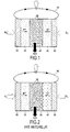
- the figure 1 illustrates a fuel cell (PAC) according to the invention.
- a PAC is considered where the first compound M1 is hydrogen (H 2 ) and the second compound N2 is oxygen (O 2 ).
- the invention also applies to reactions where the first compound is not hydrogen and / or the second compound is not oxygen.
- the anode 10 is the seat of the oxidation reaction of hydrogen: H 2 ⁇ 2 ⁇ H + + 2 ⁇ e - .
- the cathode 50 is the seat of the oxygen reduction reaction: 1 ⁇ 2 O 2 + 2 e - ⁇ O 2 -
- the first electrolyte 20, the second electrolyte 40, and the central membrane 30 are each made of a material capable of conducting protons H + and capable of conducting O 2 ions.
- the e - produced electrons circulate through the outside of the heat pump from the anode 10 through a conductor 90 to reach the cathode 50 and feed it with electrons.
- a first face of the central membrane 30 is in contact with the first electrolyte 20, and a second face of the central membrane 30, opposite this first face, is in contact with the second electrolyte 40.
- This central membrane 30 is also porous with porosities 35, in order to allow better evacuation of the water thus produced in the reaction.
- the assembly formed by the first electrolyte 20, the second electrolyte 40, and the central membrane 30, is therefore a block of the same material, the central membrane 30 additionally having porosities 35, while the electrolytes are dense.
- This set is monolithic.
- this material is a ceramic, which has the advantage of controlling its porosity during the manufacture of the PAC, for example by sintering.
- such a ceramic used as mixed conducting material for the cap is for example a barium cerate formula BACE 0, 85 Y 0.15 O 3- ⁇ with ⁇ positive, small compared to 1.
- This material is designated BCY15 and has good conduction of both H + protons and O 2- ions.
- the operation of the heat pump is carried out at a temperature of between 500 ° C. and 800 ° C.
- the inventors have shown that the efficiency of the CAP is higher in this temperature range.
- This manufacturing method makes it easier to manufacture a heat pump according to the invention.
- the densification of the first electrolyte 20 and the second electrolyte 40 can be achieved by adding a densification agent such as ZnO or CuO during sintering.
- the porosity of the central membrane 30 may be made and / or adjusted by the addition of pore-forming additives during sintering, and / or a lower sintering temperature.
- the anode 10 and the cathode 50 are for example a ceramic or a cermet (ceramic-metal composite) which are manufactured according to known methods.
- the anode 10 on one side of the first electrolyte 20 and the cathode 50 on one side of the second electrolyte 40 is deposited on these faces a layer of porous material which serves to attach to the anode 10 and the cathode 50.
- This material is for example a ceramic.
Abstract
Description
La présente invention concerne une pile à combustible comprenant une anode apte à oxyder un premier composé M1 en premiers ions M(m+) avec m entier non-nul, un premier électrolyte qui est apte à conduire ces premiers ions M(m+), et qui est en contact avec cette anode, une cathode apte à réduire un second composé N2 en seconds ions N(n-) avec n entier non-nul, un second électrolyte qui est apte à conduire ces seconds ions N(n-), et qui est en contact avec cette cathode, une membrane centrale poreuse dont une des faces est en contact avec le premier électrolyte, et dont la face opposée est en contact avec le second électrolyte.The present invention relates to a fuel cell comprising an anode capable of oxidizing a first compound M1 into first ions M (m +) with nonzero integer m, a first electrolyte which is capable of conducting these first ions M (m +) , and which is in contact with this anode, a cathode capable of reducing a second compound N2 into second ions N (n-) with n nonzero integer, a second electrolyte which is capable of conducting these second ions N (n-) , and is in contact with this cathode, a porous central membrane, one of whose faces is in contact with the first electrolyte, and whose opposite face is in contact with the second electrolyte.
Les piles à combustible (PAC) sont amenées à devenir une source de production d'énergie alternative à celles provenant directement des ressources fossiles, pour les applications stationnaires, mais aussi pour les applications embarquées (par exemple l'automobile) à plus long terme.Fuel cells (PAC) are set to become a source of alternative energy production to those coming directly from fossil fuels, for stationary applications, but also for embedded applications (for example the automobile) in the longer term.
Une PAC fonctionne sur le principe d'une oxydo-réduction électrochimique et contrôlée d'un premier composé M1 et d'un second composé N2, avec production simultanée d'électricité, du composé P et de chaleur, selon la réaction chimique globale ![]()
avec n, m, et p entiers non-nuls.A PAC operates on the principle of an electrochemical and controlled oxidation-reduction of a first compound M1 and a second compound N2, with simultaneous production of electricity, compound P and heat, according to the overall chemical reaction ![]()
with n, m, and p non-zero integers.
M1 désigne un composé d'atomes identiques ou distincts qui, en s'oxydant, donne un premier ion M(m+) (ou m premiers ions M+) et m électrons.M1 denotes a compound of identical or distinct atoms which, by oxidizing, gives a first ion M (m +) (or m first M + ions) and m electrons.
N2 désigne un composé d'atomes identiques ou distincts qui, par réduction en présence de n électrons, donne un second ion N(n-) (ou n seconds ions N-).N2 denotes a compound of identical or distinct atoms which, by reduction in the presence of n electrons, gives a second ion N (n-) (or n second ions N - ).
C'est cette électricité produite qui peut ensuite alimenter en énergie un dispositif.It is this electricity produced which can then supply energy to a device.
Par exemple, la PAC est telle que le premier composé M1 est l'hydrogène (H2) et le second composé N2 est l'oxygène (O2), et la réaction chimique globale est ![]()
![]()
Le composé produit de cette réaction est l'eau H2O.The product compound of this reaction is H 2 O.
On considère ci-dessous l'exemple d'une telle PAC.Below is an example of such a PAC.
Les inventeurs ont déjà mis au point une PAC à conduction mixte anionique et protonique (demande de brevet
Cette PAC 1 comprend cinq couches principales qui sont deux à deux en contact et dont l'empilement est, dans cet ordre :
- Une
anode 10, - Un
premier électrolyte 20, - Une membrane centrale 30,
- Un
second électrolyte 40, - Une
cathode 50.
-
Anode 10, - A
first electrolyte 20, - A
central membrane 30, - A
second electrolyte 40, - A
cathode 50.
L'anode 10 est le siège d'une réaction d'oxydation de l'hydrogène : ![]()
![]()
Les protons H+ ainsi créés migrent vers la membrane centrale 30 au travers du premier électrolyte 20. Ce premier électrolyte 20 est donc un matériau apte à conduire les protons H+.The H + protons thus created migrate towards the
Les électrons e- produits circulent par l'extérieur de la PAC depuis l'anode 10 au travers d'un conducteur 90 pour rejoindre la cathode 50 et l'alimenter en électrons (voir ci-dessous).The e - produced electrons circulate through the outside of the heat pump from the
La cathode C est le siège d'une réaction de réduction de l'oxygène : ![]()
![]()
Les ions O2- ainsi créés migrent vers la membrane centrale 30 au travers du second électrolyte 40. Ce second électrolyte 40 est donc un matériau apte à conduire les ions O2-.The O 2- ions thus created migrate towards the
Ainsi une première face de la membrane centrale 30 est en contact avec le premier électrolyte 20, et une seconde face de la membrane centrale 30, opposée à cette première face, est en contact avec le second électrolyte 40.Thus, a first face of the
La membrane centrale 30 est un composite du premier électrolyte 20 et du second électrolyte 40, de façon à être apte à conduire à la fois les protons H+ et les ions O2-.The
Au sein de cette membrane centrale 30, ces protons H+ et ces ions O2- réagissent selon la réaction suivante afin de produire de l'eau : ![]()
![]()
Cette membrane centrale 30 est en outre poreuse avec des porosités 35, afin de permettre une meilleure évacuation de l'eau ainsi produite.This
Une telle PAC présente, par rapport aux PAC à conduction simple, l'avantage d'évacuer l'eau au niveau de la membrane centrale 30 et non pas aux électrodes (anode et cathode) : en effet, lorsque l'eau est évacuée à l'anode ou à la cathode, l'eau neutralise les sites actifs (sites d'oxydation de l'hydrogène ou de réduction de l'oxygène) dans ces électrodes.Such a PAC has, compared with single-conduction heat pumps, the advantage of discharging the water at the
Cependant, cette PAC, et en général une PAC fonctionnant par oxydo-réduction d'un premier composé M1 et d'un second composé N2, présente des inconvénients :
- D'une part la fabrication de la membrane centrale 30, en général par frittage, est complexe à cause des incompatibilités physico-chimiques et thermomécaniques (coefficients de dilatation thermique différents) entre le matériau du
premier électrolyte 20 et le matériau dusecond électrolyte 40, et à cause de l'écart de température de frittage entre ces deux matériaux. - D'autre part ces incompatibilités entrainent un vieillissement prématuré de la membrane centrale 30 avec déformation et/ou fissurations de la membrane centrale 30, et/ou obturations de son réseau de porosités. Il en résulte une réduction importante des performances de la PAC.
- On the one hand, the manufacture of the
central membrane 30, generally by sintering, is complex because of the physico-chemical and thermomechanical incompatibilities (different thermal expansion coefficients) between the material of thefirst electrolyte 20 and the material of thesecond electrolyte 40, and because of the sintering temperature difference between these two materials. - On the other hand, these incompatibilities cause premature aging of the
central membrane 30 with deformation and / or cracks in thecentral membrane 30, and / or fillings of its porosity network. This results in a significant reduction in the performance of the CAP.
La présente invention vise à remédier à ces inconvénients.The present invention aims to remedy these disadvantages.
L'invention vise à proposer une pile à combustible dont la fabrication soit facilitée, et dont l'efficacité en fonctionnement soit améliorée, et dont la tenue de vie soit augmentée.The invention aims to provide a fuel cell whose manufacture is facilitated, and whose operating efficiency is improved, and whose lifespan is increased.
Ce but est atteint grâce au fait que le premier électrolyte, le second électrolyte, et la membrane centrale sont constitués du même matériau qui est apte à conduire à la fois les ions M(m+) et les ions N(n-).This object is achieved by virtue of the fact that the first electrolyte, the second electrolyte and the central membrane consist of the same material which is capable of conducting both the M (m +) ions and the N (n-) ions.
Grâce à ces dispositions, la fabrication de la pile à combustible est grandement simplifiée, car l'ensemble constitué du premier électrolyte, de la membrane centrale, et du second électrolyte peut être fabriqué en une seule opération, par exemple par frittage. La résistance mécanique et la durabilité de cet ensemble sont également améliorées.Thanks to these arrangements, the manufacture of the fuel cell is greatly simplified, since the assembly consisting of the first electrolyte, the central membrane, and the second electrolyte can be manufactured in a single operation, for example by sintering. The mechanical strength and durability of this assembly are also improved.
De plus, la superficie des sites de réaction possibles au sein de la membrane centrale est fortement augmentée. En effet, dans une PAC selon l'art antérieur, les sites de réaction entre les premiers ions (par exemple les protons H+) et les seconds ions (par exemple les ions O2-) au sein de la membrane centrale sont limités aux interfaces communes entre le matériau du premier électrolyte, le matériau du second électrolyte, et les porosités, c'est-à-dire que ces sites de réaction sont à une dimension (pluralité de courbes dans l'espace). En revanche, dans une PAC selon l'invention, les sites de réaction possibles sont constitués par les surfaces libres du matériau de la membrane centrale (c'est-à-dire l'interface entre ce matériau et les porosités). Les sites de réaction sont donc à deux dimensions (pluralité de surfaces dans l'espace), c'est-à-dire beaucoup plus nombreux. En parallèle, la résistance interne de la membrane centrale est diminuée car celle-ci présente la même conductivité ionique en tout point, à savoir la conductivité ionique du matériau la constituant (alors que dans l'art antérieur la conductivité ionique varie dans l'espace entre celle du premier électrolyte et celle du second électrolyte, ce qui rend plus tortueux les chemins de circulation des ions, et donc augmente la résistance interne de la membrane centrale).In addition, the area of the possible reaction sites within the central membrane is greatly increased. Indeed, in a PAC according to the prior art, the reaction sites between the first ions (for example the H + protons) and the second ions (for example the O 2- ions) within the central membrane are limited to common interfaces between the material of the first electrolyte, the material of the second electrolyte, and the porosities, i.e., these reaction sites are one-dimensional (plurality of curves in space). In contrast, in a PAC according to the invention, the possible reaction sites are constituted by the free surfaces of the material of the central membrane (that is to say the interface between this material and the porosities). The reaction sites are therefore two-dimensional (plurality of surfaces in space), that is to say, many more. In parallel, the internal resistance of the central membrane is reduced because it has the same ionic conductivity at all points, namely the ionic conductivity of the material constituting it (whereas in the prior art the ionic conductivity varies in space between that of the first electrolyte and that of the second electrolyte, which makes the circulation paths of the ions more tortuous, and thus increases the internal resistance of the central membrane).
L'invention sera bien comprise et ses avantages apparaîtront mieux, à la lecture de la description détaillée qui suit, d'un mode de réalisation représenté à titre d'exemple non limitatif. La description se réfère aux dessins annexés sur lesquels :
- la
figure 1 est une représentation schématique d'une pile à combustible selon l'invention. - la
figure 2 est une représentation schématique d'une pile à combustible selon l'art antérieur.
- the
figure 1 is a schematic representation of a fuel cell according to the invention. - the
figure 2 is a schematic representation of a fuel cell according to the prior art.
La
Cette PAC 1 comprend cinq couches principales qui sont deux à deux en contact et dont l'empilement est, dans cet ordre :
- Une
anode 10, - Un
premier électrolyte 20, - Une membrane centrale 30,
- Un
second électrolyte 40, - Une
cathode 50.
-
Anode 10, - A
first electrolyte 20, - A
central membrane 30, - A
second electrolyte 40, - A
cathode 50.
Dans la description ci-dessous, on considère une PAC où le premier composé M1 est l'hydrogène (H2) et le second composé N2 est l'oxygène (O2). Cependant, l'invention s'applique aussi à des réactions où le premier composé n'est pas l'hydrogène et/ou le second composé n'est pas l'oxygène.In the description below, a PAC is considered where the first compound M1 is hydrogen (H 2 ) and the second compound N2 is oxygen (O 2 ). However, the invention also applies to reactions where the first compound is not hydrogen and / or the second compound is not oxygen.
L'anode 10 est le siège de la réaction d'oxydation de l'hydrogène : ![]()
![]()
La cathode 50 est le siège de la réaction de réduction de l'oxygène : ![]()
![]()
Le premier électrolyte 20, le second électrolyte 40, et la membrane centrale 30 sont chacun constitués d'un matériau apte à conduire les protons H+ et apte à conduire les ions O2-.The
Les électrons e- produits circulent par l'extérieur de la PAC depuis l'anode 10 au travers d'un conducteur 90 pour rejoindre la cathode 50 et l'alimenter en électrons.The e - produced electrons circulate through the outside of the heat pump from the
Ainsi une première face de la membrane centrale 30 est en contact avec le premier électrolyte 20, et une seconde face de la membrane centrale 30, opposée à cette première face, est en contact avec le second électrolyte 40.Thus, a first face of the
Cette membrane centrale 30 est en outre poreuse avec des porosités 35, afin de permettre une meilleure évacuation de l'eau ainsi produite dans la réaction ![]()
![]()
Dans le cas d'une PAC fonctionnant sur la base d'une réaction différente de celle-ci, c'est le composé P, produit de cette réaction différente, qui est avantageusement évacué au travers des porosités 35.In the case of a PAC operating on the basis of a reaction different from the latter, it is the compound P, produced from this different reaction, which is advantageously discharged through the
L'ensemble formé par le premier électrolyte 20, le second électrolyte 40, et la membrane centrale 30, est donc un bloc d'un même matériau, la membrane centrale 30 présentant en supplément des porosités 35, tandis que les électrolytes sont denses. Cet ensemble est donc monolithique.The assembly formed by the
Par exemple, ce matériau est une céramique, qui présente l'avantage d'un contrôle de sa porosité durant la fabrication de la PAC, par exemple par frittage.For example, this material is a ceramic, which has the advantage of controlling its porosity during the manufacture of the PAC, for example by sintering.
Les essais réalisés par les inventeurs ont montré, de façon inattendue, que la conduction mixte simultanée des protons H+ et des ions O2- au sein de la membrane centrale 30 n'est pas erratique, mais au contraire se produit de façon efficace.The tests carried out by the inventors have unexpectedly shown that the simultaneous mixed conduction of H + protons and O 2- ions within the
En particulier, les inventeurs ont montré qu'une telle céramique à conduction mixte utilisable comme matériau pour la PAC est par exemple un cérate de barium de formule BaCe0,85Y0,15O3-δ avec δ positif, petit devant 1.In particular, the inventors have shown that such a ceramic used as mixed conducting material for the cap is for example a barium cerate formula BACE 0, 85 Y 0.15 O 3-δ with δ positive, small compared to 1.
Ce matériau est désigné par BCY15 et présente une bonne conduction à la fois des protons H+ et des ions O2-.This material is designated BCY15 and has good conduction of both H + protons and O 2- ions.
Avantageusement, le fonctionnement de la PAC s'effectue à une température comprise entre 500°C et 800°C.Advantageously, the operation of the heat pump is carried out at a temperature of between 500 ° C. and 800 ° C.
En effet, les inventeurs ont montré que le rendement de la PAC était supérieur dans cette plage de températures.Indeed, the inventors have shown that the efficiency of the CAP is higher in this temperature range.
Les inventeurs ont réalisé une PAC selon l'invention comprenant plusieurs couches par combinaison des procédés suivants :
- La formation et l'assemblage du
premier électrolyte 20, dusecond électrolyte 40, et de lamembrane centrale 30 par une compression à froid et un frittage du matériau constituant ces couches, - La fixation de l'anode 10 sur le
premier électrolyte 20 et de lacathode 50 sur lesecond électrolyte 40 par un procédé de déposition, par exemple la sérigraphie ou le coulage en bande (en anglais "tape casting"), - La densification du premier électrolyte 20 et du
second électrolyte 40 lors du frittage, - L'ajustement de la porosité de la
membrane centrale 30.
- The formation and assembly of the
first electrolyte 20, thesecond electrolyte 40, and thecentral membrane 30 by a cold compression and a sintering of the material constituting these layers, - Fixing the
anode 10 on thefirst electrolyte 20 and thecathode 50 on thesecond electrolyte 40 by a deposition process, for example screen printing or tape casting (in English "tape casting"), - Densification of the
first electrolyte 20 and thesecond electrolyte 40 during sintering, - The adjustment of the porosity of the
central membrane 30.
Ce procédé de fabrication permet de faciliter la fabrication d'une PAC selon l'invention.This manufacturing method makes it easier to manufacture a heat pump according to the invention.
La densification du premier électrolyte 20 et du second électrolyte 40 peut être réalisée par l'ajout d'un agent de densification tel que ZnO ou CuO lors du frittage.The densification of the
La porosité de la membrane centrale 30 peut être réalisée et/ou ajustée par l'ajout d'additifs favorisant la formation de pores lors du frittage, et/ou une température de frittage plus basse.The porosity of the
L'anode 10 et la cathode 50 sont par exemple une céramique ou un cermet (composite céramique-métal) qui sont fabriqués selon des procédés connus.The
Par exemple, la composition d'une PAC, où on utilise la notation {anode/1er électrolyte/membrane centrale/2ème électrolyte/cathode} est une des suivantes :
- BCY15-Ni/BCY15 dense/BCY poreux/BCY15 dense/BCY15-LSCF
ou - BCY15-Ni/BCY15 dense/BCY poreux/BCY15 dense/BCY15-Ag
où LSCF désigne la céramique de formule La1-xSrxCo1-YFeYO3-δ avec X et Y compris entre 0 et 1, et δ positif, petit devant 1.
- BCY15-Ni / dense BCY15 / porous BCY / dense BCY15 / BCY15-LSCF
or - BCY15-Ni / dense BCY15 / porous BCY / dense BCY15 / BCY15-Ag
where LSCF designates the ceramic of formula La 1-x Sr x Co 1 -Y Fe Y O 3-δ with X and Y between 0 and 1, and δ positive, small in front of 1.
Avantageusement, avant la fixation de l'anode 10 sur une face du premier électrolyte 20 et de la cathode 50 sur une face du second électrolyte 40, on dépose sur ces faces une couche de matériau poreux qui sert d'accroche à l'anode 10 et à la cathode 50.Advantageously, before fixing the
Dans le cas général d'une PAC fonctionnant sur le principe d'une oxydo-réduction électrochimique et contrôlée d'un premier composé (M1) et d'un second composé (N2), les conclusions ci-dessus sont applicables, le même matériau utilisé comme premier électrolyte, second électrolyte, et membrane centrale étant apte à conduire à la fois les ions M(m+) et les ions N(n-).In the general case of a PAC operating on the principle of an electrochemical and controlled oxidation-reduction of a first compound (M1) and a second compound (N2), the above conclusions are applicable, the same material used as first electrolyte, second electrolyte, and central membrane being capable of conducting both M (m +) ions and N (n-) ions.
Ce matériau est par exemple une céramique.This material is for example a ceramic.
Claims (8)
Applications Claiming Priority (1)
| Application Number | Priority Date | Filing Date | Title |
|---|---|---|---|
| FR1060705A FR2969395B1 (en) | 2010-12-17 | 2010-12-17 | FUEL CELL WITH MONOLITHIC MEMBRANE ELECTROLYTES ASSEMBLY |
Publications (2)
| Publication Number | Publication Date |
|---|---|
| EP2466673A1 true EP2466673A1 (en) | 2012-06-20 |
| EP2466673B1 EP2466673B1 (en) | 2017-03-22 |
Family
ID=43768914
Family Applications (1)
| Application Number | Title | Priority Date | Filing Date |
|---|---|---|---|
| EP11193831.2A Not-in-force EP2466673B1 (en) | 2010-12-17 | 2011-12-15 | Fuel cell with monolithic electrolyte-membrane assembly |
Country Status (5)
| Country | Link |
|---|---|
| US (1) | US20120156573A1 (en) |
| EP (1) | EP2466673B1 (en) |
| JP (1) | JP2012142274A (en) |
| ES (1) | ES2628517T3 (en) |
| FR (1) | FR2969395B1 (en) |
Families Citing this family (1)
| Publication number | Priority date | Publication date | Assignee | Title |
|---|---|---|---|---|
| CN109686986B (en) * | 2018-11-02 | 2020-12-08 | 全球能源互联网研究院有限公司 | One-way electronic conduction solid oxide fuel cell and preparation method thereof |
Citations (6)
| Publication number | Priority date | Publication date | Assignee | Title |
|---|---|---|---|---|
| WO2005086272A1 (en) * | 2004-03-04 | 2005-09-15 | Toyota Jidosha Kabushiki Kaisha | Solid oxide fuel cell with multilayer electrolyte |
| US20060093884A1 (en) * | 2004-10-29 | 2006-05-04 | Seabaugh Matthew M | Ceramic laminate structures |
| US20060199058A1 (en) * | 2005-03-04 | 2006-09-07 | Toto Ltd. | Solid oxide fuel cell |
| WO2006097663A2 (en) | 2005-03-17 | 2006-09-21 | Armines | High temperature fuel cell with mixed anionic and protonic conduction |
| JP2009054519A (en) * | 2007-08-29 | 2009-03-12 | Toyota Motor Corp | Electrode-electrolyte membrane assembly, and manufacturing method thereof |
| US20100167169A1 (en) * | 2008-12-08 | 2010-07-01 | Nextech Materials, Ltd | Current Collectors for Solid Oxide Fuel Cell Stacks |
Family Cites Families (5)
| Publication number | Priority date | Publication date | Assignee | Title |
|---|---|---|---|---|
| US5445903A (en) * | 1993-09-09 | 1995-08-29 | Technology Management, Inc. | Electrochemical apparatus |
| DE69505784T2 (en) * | 1995-02-09 | 1999-05-06 | Tokyo Yogyo Kk | Solid electrolyte for a fuel cell and its manufacturing process |
| US6645656B1 (en) * | 2000-03-24 | 2003-11-11 | University Of Houston | Thin film solid oxide fuel cell and method for forming |
| EP1369949B1 (en) * | 2002-06-06 | 2013-01-30 | Panasonic Corporation | Solid electrolyte fuel cell and manufacturing method thereof |
| US8821968B2 (en) * | 2007-10-31 | 2014-09-02 | The Board Of Trustees Of The Leland Stanford Junior University | Process for making layer-structured catalysts at the electrode/electrolyte interface of a fuel cell |
-
2010
- 2010-12-17 FR FR1060705A patent/FR2969395B1/en not_active Expired - Fee Related
-
2011
- 2011-12-15 EP EP11193831.2A patent/EP2466673B1/en not_active Not-in-force
- 2011-12-15 JP JP2011274744A patent/JP2012142274A/en active Pending
- 2011-12-15 US US13/326,950 patent/US20120156573A1/en not_active Abandoned
- 2011-12-15 ES ES11193831.2T patent/ES2628517T3/en active Active
Patent Citations (6)
| Publication number | Priority date | Publication date | Assignee | Title |
|---|---|---|---|---|
| WO2005086272A1 (en) * | 2004-03-04 | 2005-09-15 | Toyota Jidosha Kabushiki Kaisha | Solid oxide fuel cell with multilayer electrolyte |
| US20060093884A1 (en) * | 2004-10-29 | 2006-05-04 | Seabaugh Matthew M | Ceramic laminate structures |
| US20060199058A1 (en) * | 2005-03-04 | 2006-09-07 | Toto Ltd. | Solid oxide fuel cell |
| WO2006097663A2 (en) | 2005-03-17 | 2006-09-21 | Armines | High temperature fuel cell with mixed anionic and protonic conduction |
| JP2009054519A (en) * | 2007-08-29 | 2009-03-12 | Toyota Motor Corp | Electrode-electrolyte membrane assembly, and manufacturing method thereof |
| US20100167169A1 (en) * | 2008-12-08 | 2010-07-01 | Nextech Materials, Ltd | Current Collectors for Solid Oxide Fuel Cell Stacks |
Non-Patent Citations (3)
| Title |
|---|
| BABILO P; HAILE S M: "Enhanced sintering of yttrium-doped barium zirconate by addition of ZnO", JOURNAL OF THE AMERICAN CERAMIC SOCIETY, vol. 88, no. 9, September 2005 (2005-09-01), pages 2362 - 2365, XP002630796, DOI: 10.1111/j.1551-2916.2005.00449.x * |
| HA S B ET AL: "Effect of oxide additives on the sintering behavior and electrical properties of strontium- and magnesium-doped lanthanum gallate", JOURNAL OF THE EUROPEAN CERAMIC SOCIETY, ELSEVIER SCIENCE PUBLISHERS, BARKING, ESSEX, GB, vol. 30, no. 12, 1 September 2010 (2010-09-01), pages 2593 - 2601, XP027107080, ISSN: 0955-2219, [retrieved on 20100625] * |
| XIAN-ZHU FU, JING-LI LUO, ALAN R. SANGER, ZHENG-RONG XU, KARL T. CHUANG: "Fabrication of bi-layered proton conducting membrane for hydrocarbon solid oxide fuel cell reactors", ELECTROCHIMICA ACTA, vol. 55, 13 October 2009 (2009-10-13), pages 1145 - 1149, XP002630795 * |
Also Published As
| Publication number | Publication date |
|---|---|
| EP2466673B1 (en) | 2017-03-22 |
| JP2012142274A (en) | 2012-07-26 |
| ES2628517T3 (en) | 2017-08-03 |
| FR2969395A1 (en) | 2012-06-22 |
| US20120156573A1 (en) | 2012-06-21 |
| FR2969395B1 (en) | 2013-01-11 |
Similar Documents
| Publication | Publication Date | Title |
|---|---|---|
| Fabbri et al. | Towards the next generation of solid oxide fuel cells operating below 600 C with chemically stable proton‐conducting electrolytes | |
| US8993189B2 (en) | Heat-resistant alloy, alloy member for fuel cell, fuel cell stack device, fuel cell module, and fuel cell device | |
| EP2774202B1 (en) | Fuel cell including a cathode having channels | |
| JP3777903B2 (en) | Solid oxide fuel cell with gradient composition between electrode and electrolyte | |
| US7781123B2 (en) | Method and apparatus for forming electrode interconnect contacts for a solid-oxide fuel cell stack | |
| WO2011154516A1 (en) | Method for manufacturing basic electrochemical cells for energy or hydrogen-producing electrochemical systems, in particular of the sofc and hte type | |
| US20090297906A1 (en) | Fuel cell and method of producing the fuel cell | |
| JP4853979B2 (en) | Fuel cell | |
| JP2010021056A (en) | Fuel cell and method for manufacturing same | |
| JP4544872B2 (en) | Fuel cell and fuel cell | |
| JP4859522B2 (en) | Solid oxide fuel cell and manufacturing method thereof | |
| KR101260856B1 (en) | Dual layer interconnect for solid oxide fuel cell, solid oxide fuel cell therewith and preparation method thereof | |
| KR20170121289A (en) | Title: TITANIUM MATERIAL, SEPARATOR, AND SOLID POLYMERIC FUEL CELL, AND METHOD FOR MANUFACTURING TITANIUM MATERIAL | |
| EP1528615A2 (en) | Fuel cell | |
| CA3008699C (en) | Proton-conductive electrochemical device with integrated reforming and associated production method | |
| EP2466673B1 (en) | Fuel cell with monolithic electrolyte-membrane assembly | |
| US20090162723A1 (en) | Integrated Single-Chamber Solid Oxide Fuel Cells | |
| FR3024289A1 (en) | FUEL CELL DEVICE | |
| EP2270914B1 (en) | Fuel cell with built-in hydrogen purification membrane | |
| JP4881479B2 (en) | Fuel cell | |
| WO2020261935A1 (en) | Fuel electrode-solid electrolyte layer composite body, fuel electrode-solid electrolyte layer composite member, fuel cell and method for producing fuel cell | |
| US20050221140A1 (en) | Solid oxide fuel cell | |
| US11063271B2 (en) | Electrolyte with embedded metal for solid oxide electrochemical devices | |
| JP2010516035A (en) | Structure of cathode for solid oxide fuel cell | |
| JP4557578B2 (en) | Fuel cell, cell stack and fuel cell |
Legal Events
| Date | Code | Title | Description |
|---|---|---|---|
| PUAI | Public reference made under article 153(3) epc to a published international application that has entered the european phase |
Free format text: ORIGINAL CODE: 0009012 |
|
| AK | Designated contracting states |
Kind code of ref document: A1 Designated state(s): AL AT BE BG CH CY CZ DE DK EE ES FI FR GB GR HR HU IE IS IT LI LT LU LV MC MK MT NL NO PL PT RO RS SE SI SK SM TR |
|
| AX | Request for extension of the european patent |
Extension state: BA ME |
|
| 17P | Request for examination filed |
Effective date: 20121212 |
|
| 17Q | First examination report despatched |
Effective date: 20140131 |
|
| REG | Reference to a national code |
Ref country code: DE Ref legal event code: R079 Ref document number: 602011036163 Country of ref document: DE Free format text: PREVIOUS MAIN CLASS: H01M0004860000 Ipc: H01M0008122600 |
|
| RIC1 | Information provided on ipc code assigned before grant |
Ipc: H01M 4/86 20060101ALI20160902BHEP Ipc: H01M 8/1226 20160101AFI20160902BHEP Ipc: H01M 8/0245 20160101ALI20160902BHEP Ipc: H01M 8/124 20160101ALI20160902BHEP Ipc: H01M 4/90 20060101ALI20160902BHEP Ipc: H01M 8/126 20160101ALI20160902BHEP Ipc: H01M 4/88 20060101ALI20160902BHEP Ipc: H01M 8/023 20160101ALI20160902BHEP Ipc: H01M 8/0236 20160101ALI20160902BHEP |
|
| GRAP | Despatch of communication of intention to grant a patent |
Free format text: ORIGINAL CODE: EPIDOSNIGR1 |
|
| INTG | Intention to grant announced |
Effective date: 20161021 |
|
| GRAS | Grant fee paid |
Free format text: ORIGINAL CODE: EPIDOSNIGR3 |
|
| GRAA | (expected) grant |
Free format text: ORIGINAL CODE: 0009210 |
|
| AK | Designated contracting states |
Kind code of ref document: B1 Designated state(s): AL AT BE BG CH CY CZ DE DK EE ES FI FR GB GR HR HU IE IS IT LI LT LU LV MC MK MT NL NO PL PT RO RS SE SI SK SM TR |
|
| REG | Reference to a national code |
Ref country code: GB Ref legal event code: FG4D Free format text: NOT ENGLISH |
|
| REG | Reference to a national code |
Ref country code: CH Ref legal event code: EP |
|
| REG | Reference to a national code |
Ref country code: AT Ref legal event code: REF Ref document number: 878573 Country of ref document: AT Kind code of ref document: T Effective date: 20170415 |
|
| REG | Reference to a national code |
Ref country code: IE Ref legal event code: FG4D Free format text: LANGUAGE OF EP DOCUMENT: FRENCH |
|
| REG | Reference to a national code |
Ref country code: DE Ref legal event code: R096 Ref document number: 602011036163 Country of ref document: DE |
|
| REG | Reference to a national code |
Ref country code: NL Ref legal event code: FP |
|
| PG25 | Lapsed in a contracting state [announced via postgrant information from national office to epo] |
Ref country code: LT Free format text: LAPSE BECAUSE OF FAILURE TO SUBMIT A TRANSLATION OF THE DESCRIPTION OR TO PAY THE FEE WITHIN THE PRESCRIBED TIME-LIMIT Effective date: 20170322 Ref country code: NO Free format text: LAPSE BECAUSE OF FAILURE TO SUBMIT A TRANSLATION OF THE DESCRIPTION OR TO PAY THE FEE WITHIN THE PRESCRIBED TIME-LIMIT Effective date: 20170622 Ref country code: FI Free format text: LAPSE BECAUSE OF FAILURE TO SUBMIT A TRANSLATION OF THE DESCRIPTION OR TO PAY THE FEE WITHIN THE PRESCRIBED TIME-LIMIT Effective date: 20170322 Ref country code: GR Free format text: LAPSE BECAUSE OF FAILURE TO SUBMIT A TRANSLATION OF THE DESCRIPTION OR TO PAY THE FEE WITHIN THE PRESCRIBED TIME-LIMIT Effective date: 20170623 Ref country code: HR Free format text: LAPSE BECAUSE OF FAILURE TO SUBMIT A TRANSLATION OF THE DESCRIPTION OR TO PAY THE FEE WITHIN THE PRESCRIBED TIME-LIMIT Effective date: 20170322 |
|
| REG | Reference to a national code |
Ref country code: ES Ref legal event code: FG2A Ref document number: 2628517 Country of ref document: ES Kind code of ref document: T3 Effective date: 20170803 |
|
| REG | Reference to a national code |
Ref country code: LT Ref legal event code: MG4D |
|
| REG | Reference to a national code |
Ref country code: AT Ref legal event code: MK05 Ref document number: 878573 Country of ref document: AT Kind code of ref document: T Effective date: 20170322 Ref country code: CH Ref legal event code: NV Representative=s name: MICHELI AND CIE SA, CH |
|
| PG25 | Lapsed in a contracting state [announced via postgrant information from national office to epo] |
Ref country code: BG Free format text: LAPSE BECAUSE OF FAILURE TO SUBMIT A TRANSLATION OF THE DESCRIPTION OR TO PAY THE FEE WITHIN THE PRESCRIBED TIME-LIMIT Effective date: 20170622 Ref country code: SE Free format text: LAPSE BECAUSE OF FAILURE TO SUBMIT A TRANSLATION OF THE DESCRIPTION OR TO PAY THE FEE WITHIN THE PRESCRIBED TIME-LIMIT Effective date: 20170322 Ref country code: LV Free format text: LAPSE BECAUSE OF FAILURE TO SUBMIT A TRANSLATION OF THE DESCRIPTION OR TO PAY THE FEE WITHIN THE PRESCRIBED TIME-LIMIT Effective date: 20170322 Ref country code: RS Free format text: LAPSE BECAUSE OF FAILURE TO SUBMIT A TRANSLATION OF THE DESCRIPTION OR TO PAY THE FEE WITHIN THE PRESCRIBED TIME-LIMIT Effective date: 20170322 |
|
| PG25 | Lapsed in a contracting state [announced via postgrant information from national office to epo] |
Ref country code: CZ Free format text: LAPSE BECAUSE OF FAILURE TO SUBMIT A TRANSLATION OF THE DESCRIPTION OR TO PAY THE FEE WITHIN THE PRESCRIBED TIME-LIMIT Effective date: 20170322 Ref country code: AT Free format text: LAPSE BECAUSE OF FAILURE TO SUBMIT A TRANSLATION OF THE DESCRIPTION OR TO PAY THE FEE WITHIN THE PRESCRIBED TIME-LIMIT Effective date: 20170322 Ref country code: SK Free format text: LAPSE BECAUSE OF FAILURE TO SUBMIT A TRANSLATION OF THE DESCRIPTION OR TO PAY THE FEE WITHIN THE PRESCRIBED TIME-LIMIT Effective date: 20170322 Ref country code: EE Free format text: LAPSE BECAUSE OF FAILURE TO SUBMIT A TRANSLATION OF THE DESCRIPTION OR TO PAY THE FEE WITHIN THE PRESCRIBED TIME-LIMIT Effective date: 20170322 Ref country code: RO Free format text: LAPSE BECAUSE OF FAILURE TO SUBMIT A TRANSLATION OF THE DESCRIPTION OR TO PAY THE FEE WITHIN THE PRESCRIBED TIME-LIMIT Effective date: 20170322 |
|
| PG25 | Lapsed in a contracting state [announced via postgrant information from national office to epo] |
Ref country code: PL Free format text: LAPSE BECAUSE OF FAILURE TO SUBMIT A TRANSLATION OF THE DESCRIPTION OR TO PAY THE FEE WITHIN THE PRESCRIBED TIME-LIMIT Effective date: 20170322 Ref country code: PT Free format text: LAPSE BECAUSE OF FAILURE TO SUBMIT A TRANSLATION OF THE DESCRIPTION OR TO PAY THE FEE WITHIN THE PRESCRIBED TIME-LIMIT Effective date: 20170724 Ref country code: IS Free format text: LAPSE BECAUSE OF FAILURE TO SUBMIT A TRANSLATION OF THE DESCRIPTION OR TO PAY THE FEE WITHIN THE PRESCRIBED TIME-LIMIT Effective date: 20170722 Ref country code: SM Free format text: LAPSE BECAUSE OF FAILURE TO SUBMIT A TRANSLATION OF THE DESCRIPTION OR TO PAY THE FEE WITHIN THE PRESCRIBED TIME-LIMIT Effective date: 20170322 |
|
| REG | Reference to a national code |
Ref country code: FR Ref legal event code: PLFP Year of fee payment: 7 |
|
| REG | Reference to a national code |
Ref country code: DE Ref legal event code: R097 Ref document number: 602011036163 Country of ref document: DE |
|
| PLBE | No opposition filed within time limit |
Free format text: ORIGINAL CODE: 0009261 |
|
| STAA | Information on the status of an ep patent application or granted ep patent |
Free format text: STATUS: NO OPPOSITION FILED WITHIN TIME LIMIT |
|
| PG25 | Lapsed in a contracting state [announced via postgrant information from national office to epo] |
Ref country code: DK Free format text: LAPSE BECAUSE OF FAILURE TO SUBMIT A TRANSLATION OF THE DESCRIPTION OR TO PAY THE FEE WITHIN THE PRESCRIBED TIME-LIMIT Effective date: 20170322 |
|
| 26N | No opposition filed |
Effective date: 20180102 |
|
| PG25 | Lapsed in a contracting state [announced via postgrant information from national office to epo] |
Ref country code: SI Free format text: LAPSE BECAUSE OF FAILURE TO SUBMIT A TRANSLATION OF THE DESCRIPTION OR TO PAY THE FEE WITHIN THE PRESCRIBED TIME-LIMIT Effective date: 20170322 |
|
| REG | Reference to a national code |
Ref country code: IE Ref legal event code: MM4A |
|
| PG25 | Lapsed in a contracting state [announced via postgrant information from national office to epo] |
Ref country code: MT Free format text: LAPSE BECAUSE OF FAILURE TO SUBMIT A TRANSLATION OF THE DESCRIPTION OR TO PAY THE FEE WITHIN THE PRESCRIBED TIME-LIMIT Effective date: 20170322 Ref country code: LU Free format text: LAPSE BECAUSE OF NON-PAYMENT OF DUE FEES Effective date: 20171215 |
|
| REG | Reference to a national code |
Ref country code: BE Ref legal event code: MM Effective date: 20171231 |
|
| PG25 | Lapsed in a contracting state [announced via postgrant information from national office to epo] |
Ref country code: IE Free format text: LAPSE BECAUSE OF NON-PAYMENT OF DUE FEES Effective date: 20171215 |
|
| PG25 | Lapsed in a contracting state [announced via postgrant information from national office to epo] |
Ref country code: BE Free format text: LAPSE BECAUSE OF NON-PAYMENT OF DUE FEES Effective date: 20171231 |
|
| PGFP | Annual fee paid to national office [announced via postgrant information from national office to epo] |
Ref country code: NL Payment date: 20181114 Year of fee payment: 8 |
|
| PGFP | Annual fee paid to national office [announced via postgrant information from national office to epo] |
Ref country code: DE Payment date: 20181211 Year of fee payment: 8 |
|
| PGFP | Annual fee paid to national office [announced via postgrant information from national office to epo] |
Ref country code: IT Payment date: 20181211 Year of fee payment: 8 Ref country code: FR Payment date: 20181220 Year of fee payment: 8 Ref country code: CH Payment date: 20181219 Year of fee payment: 8 Ref country code: GB Payment date: 20181218 Year of fee payment: 8 |
|
| PGFP | Annual fee paid to national office [announced via postgrant information from national office to epo] |
Ref country code: ES Payment date: 20190125 Year of fee payment: 8 |
|
| PG25 | Lapsed in a contracting state [announced via postgrant information from national office to epo] |
Ref country code: MC Free format text: LAPSE BECAUSE OF FAILURE TO SUBMIT A TRANSLATION OF THE DESCRIPTION OR TO PAY THE FEE WITHIN THE PRESCRIBED TIME-LIMIT Effective date: 20170322 Ref country code: HU Free format text: LAPSE BECAUSE OF FAILURE TO SUBMIT A TRANSLATION OF THE DESCRIPTION OR TO PAY THE FEE WITHIN THE PRESCRIBED TIME-LIMIT; INVALID AB INITIO Effective date: 20111215 |
|
| PG25 | Lapsed in a contracting state [announced via postgrant information from national office to epo] |
Ref country code: CY Free format text: LAPSE BECAUSE OF NON-PAYMENT OF DUE FEES Effective date: 20170322 |
|
| PG25 | Lapsed in a contracting state [announced via postgrant information from national office to epo] |
Ref country code: MK Free format text: LAPSE BECAUSE OF FAILURE TO SUBMIT A TRANSLATION OF THE DESCRIPTION OR TO PAY THE FEE WITHIN THE PRESCRIBED TIME-LIMIT Effective date: 20170322 |
|
| PG25 | Lapsed in a contracting state [announced via postgrant information from national office to epo] |
Ref country code: TR Free format text: LAPSE BECAUSE OF FAILURE TO SUBMIT A TRANSLATION OF THE DESCRIPTION OR TO PAY THE FEE WITHIN THE PRESCRIBED TIME-LIMIT Effective date: 20170322 |
|
| REG | Reference to a national code |
Ref country code: DE Ref legal event code: R119 Ref document number: 602011036163 Country of ref document: DE |
|
| PG25 | Lapsed in a contracting state [announced via postgrant information from national office to epo] |
Ref country code: AL Free format text: LAPSE BECAUSE OF FAILURE TO SUBMIT A TRANSLATION OF THE DESCRIPTION OR TO PAY THE FEE WITHIN THE PRESCRIBED TIME-LIMIT Effective date: 20170322 |
|
| REG | Reference to a national code |
Ref country code: CH Ref legal event code: PL |
|
| REG | Reference to a national code |
Ref country code: NL Ref legal event code: MM Effective date: 20200101 |
|
| GBPC | Gb: european patent ceased through non-payment of renewal fee |
Effective date: 20191215 |
|
| PG25 | Lapsed in a contracting state [announced via postgrant information from national office to epo] |
Ref country code: NL Free format text: LAPSE BECAUSE OF NON-PAYMENT OF DUE FEES Effective date: 20200101 |
|
| PG25 | Lapsed in a contracting state [announced via postgrant information from national office to epo] |
Ref country code: IT Free format text: LAPSE BECAUSE OF NON-PAYMENT OF DUE FEES Effective date: 20191215 Ref country code: FR Free format text: LAPSE BECAUSE OF NON-PAYMENT OF DUE FEES Effective date: 20191231 Ref country code: GB Free format text: LAPSE BECAUSE OF NON-PAYMENT OF DUE FEES Effective date: 20191215 Ref country code: DE Free format text: LAPSE BECAUSE OF NON-PAYMENT OF DUE FEES Effective date: 20200701 |
|
| PG25 | Lapsed in a contracting state [announced via postgrant information from national office to epo] |
Ref country code: LI Free format text: LAPSE BECAUSE OF NON-PAYMENT OF DUE FEES Effective date: 20191231 Ref country code: CH Free format text: LAPSE BECAUSE OF NON-PAYMENT OF DUE FEES Effective date: 20191231 |
|
| REG | Reference to a national code |
Ref country code: ES Ref legal event code: FD2A Effective date: 20210601 |
|
| PG25 | Lapsed in a contracting state [announced via postgrant information from national office to epo] |
Ref country code: ES Free format text: LAPSE BECAUSE OF NON-PAYMENT OF DUE FEES Effective date: 20191216 |