EP2445032A1 - Battery module - Google Patents
Battery module Download PDFInfo
- Publication number
- EP2445032A1 EP2445032A1 EP11173734A EP11173734A EP2445032A1 EP 2445032 A1 EP2445032 A1 EP 2445032A1 EP 11173734 A EP11173734 A EP 11173734A EP 11173734 A EP11173734 A EP 11173734A EP 2445032 A1 EP2445032 A1 EP 2445032A1
- Authority
- EP
- European Patent Office
- Prior art keywords
- cover
- battery module
- battery
- extending
- degassing
- Prior art date
- Legal status (The legal status is an assumption and is not a legal conclusion. Google has not performed a legal analysis and makes no representation as to the accuracy of the status listed.)
- Granted
Links
- 238000007872 degassing Methods 0.000 claims abstract description 86
- 230000004308 accommodation Effects 0.000 claims description 35
- 230000008878 coupling Effects 0.000 claims description 26
- 238000010168 coupling process Methods 0.000 claims description 26
- 238000005859 coupling reaction Methods 0.000 claims description 26
- 230000003014 reinforcing effect Effects 0.000 claims description 8
- 238000004891 communication Methods 0.000 claims description 4
- 230000000903 blocking effect Effects 0.000 description 7
- 238000002955 isolation Methods 0.000 description 6
- 238000007789 sealing Methods 0.000 description 6
- 239000003792 electrolyte Substances 0.000 description 5
- 238000003780 insertion Methods 0.000 description 5
- 230000037431 insertion Effects 0.000 description 5
- PXHVJJICTQNCMI-UHFFFAOYSA-N Nickel Chemical compound [Ni] PXHVJJICTQNCMI-UHFFFAOYSA-N 0.000 description 2
- 238000003487 electrochemical reaction Methods 0.000 description 2
- WHXSMMKQMYFTQS-UHFFFAOYSA-N Lithium Chemical compound [Li] WHXSMMKQMYFTQS-UHFFFAOYSA-N 0.000 description 1
- HBBGRARXTFLTSG-UHFFFAOYSA-N Lithium ion Chemical compound [Li+] HBBGRARXTFLTSG-UHFFFAOYSA-N 0.000 description 1
- 230000002411 adverse Effects 0.000 description 1
- 239000006227 byproduct Substances 0.000 description 1
- 238000007796 conventional method Methods 0.000 description 1
- 230000003247 decreasing effect Effects 0.000 description 1
- 238000013461 design Methods 0.000 description 1
- 229910052744 lithium Inorganic materials 0.000 description 1
- 229910001416 lithium ion Inorganic materials 0.000 description 1
- 239000000463 material Substances 0.000 description 1
- 229910052759 nickel Inorganic materials 0.000 description 1
- 239000011255 nonaqueous electrolyte Substances 0.000 description 1
- 229920000642 polymer Polymers 0.000 description 1
- 238000007086 side reaction Methods 0.000 description 1
Images


Classifications
-
- H—ELECTRICITY
- H01—ELECTRIC ELEMENTS
- H01M—PROCESSES OR MEANS, e.g. BATTERIES, FOR THE DIRECT CONVERSION OF CHEMICAL ENERGY INTO ELECTRICAL ENERGY
- H01M50/00—Constructional details or processes of manufacture of the non-active parts of electrochemical cells other than fuel cells, e.g. hybrid cells
- H01M50/30—Arrangements for facilitating escape of gases
-
- H—ELECTRICITY
- H01—ELECTRIC ELEMENTS
- H01M—PROCESSES OR MEANS, e.g. BATTERIES, FOR THE DIRECT CONVERSION OF CHEMICAL ENERGY INTO ELECTRICAL ENERGY
- H01M50/00—Constructional details or processes of manufacture of the non-active parts of electrochemical cells other than fuel cells, e.g. hybrid cells
- H01M50/10—Primary casings, jackets or wrappings of a single cell or a single battery
- H01M50/147—Lids or covers
-
- H—ELECTRICITY
- H01—ELECTRIC ELEMENTS
- H01M—PROCESSES OR MEANS, e.g. BATTERIES, FOR THE DIRECT CONVERSION OF CHEMICAL ENERGY INTO ELECTRICAL ENERGY
- H01M50/00—Constructional details or processes of manufacture of the non-active parts of electrochemical cells other than fuel cells, e.g. hybrid cells
- H01M50/30—Arrangements for facilitating escape of gases
- H01M50/308—Detachable arrangements, e.g. detachable vent plugs or plug systems
-
- H—ELECTRICITY
- H01—ELECTRIC ELEMENTS
- H01M—PROCESSES OR MEANS, e.g. BATTERIES, FOR THE DIRECT CONVERSION OF CHEMICAL ENERGY INTO ELECTRICAL ENERGY
- H01M50/00—Constructional details or processes of manufacture of the non-active parts of electrochemical cells other than fuel cells, e.g. hybrid cells
- H01M50/50—Current conducting connections for cells or batteries
- H01M50/543—Terminals
-
- Y—GENERAL TAGGING OF NEW TECHNOLOGICAL DEVELOPMENTS; GENERAL TAGGING OF CROSS-SECTIONAL TECHNOLOGIES SPANNING OVER SEVERAL SECTIONS OF THE IPC; TECHNICAL SUBJECTS COVERED BY FORMER USPC CROSS-REFERENCE ART COLLECTIONS [XRACs] AND DIGESTS
- Y02—TECHNOLOGIES OR APPLICATIONS FOR MITIGATION OR ADAPTATION AGAINST CLIMATE CHANGE
- Y02E—REDUCTION OF GREENHOUSE GAS [GHG] EMISSIONS, RELATED TO ENERGY GENERATION, TRANSMISSION OR DISTRIBUTION
- Y02E60/00—Enabling technologies; Technologies with a potential or indirect contribution to GHG emissions mitigation
- Y02E60/10—Energy storage using batteries
Definitions
- aspects of embodiments of the present invention relate to a battery module having a plurality of battery cells.
- the high-output battery module is formed to have high capacity by constituting a plurality of battery cells connected in series so that the battery module may be used to drive a motor of a device using high power, such as an electric vehicle.
- a battery cell includes an electrode assembly constituted by a positive plate and a negative plate, and an electrolyte, and generates energy by an electrochemical reaction of the plates with the electrolyte.
- gas may be generated in the battery cell due to a side reaction of the electrochemical reaction.
- a path or a vent for the gas may be formed in the battery module in order to efficiently treat the gas generated in a plurality of battery cells.
- the present invention is directed to the battery module cover, the battery module and the battery pack as defined in the claims and/or as disclosed below.
- the battery module cover of the invention comprises a degassing cover comprising:
- a battery module cover improves assembly of a plurality of battery cells.
- a battery module has a structure for reliably preventing or reducing leakage of gas generated in a plurality of battery cells.
- a battery module includes: a plurality of battery cells arranged in a first direction from a first end of the battery module to a second end of the battery module, each of the battery cells including a case including a vent, an electrode assembly housed in the case, and a terminal electrically coupled to the electrode assembly; a bus bar coupled between the terminals of adjacent battery cells of the plurality of battery cells; and a battery module cover covering the plurality of battery cells and including a degassing cover covering the vents of the plurality of battery cells, and a bus bar cover covering the terminals of the plurality of battery cells and the bus bar.
- the degassing cover and the bus bar cover may be integrally formed.
- the degassing cover includes at least one protrusion extending from a surface of the degassing cover facing the plurality of battery cells, the at least one protrusion defining a cavity covering the vents of the plurality of battery cells.
- the degassing cover further includes an exhaust part extending from the degassing cover at the first end of the battery module, and the at least one protrusion has an opening between the cavity and the exhaust part.
- the exhaust part may include a first exhaust portion extending from the degassing cover; and at least one second exhaust portion extending from the first exhaust portion in a direction perpendicular to the first exhaust portion, the at least one second exhaust portion having an exhaust opening at an end thereof.
- a battery module further includes sealing members adjacent the vents, and the at least one protrusion contacts the sealing members.
- the at least one protrusion includes a first pair of ribs extending in the first direction and a second pair of ribs between the first pair of ribs and extending in the first direction.
- a battery module further includes a housing receiving the plurality of battery cells, the housing including a pair of end plates contacting outermost battery cells of the plurality of battery cells at the first and second ends of the battery module; and a connecting member extending in the first direction and coupling the end plates to each other.
- An end plate of the pair of end plates may include a projection extending toward the battery module cover and having an opening formed therein, the opening receiving an exhaust part extending from the degassing cover at the first end of the battery module.
- the battery module cover may have an accommodation space at at least one of the first and second ends of the battery module and spaced apart from the cavity, and the projection of the end plate may be received in the accommodation space.
- the battery module cover may include a plurality of ribs intersecting one another at reinforcing portions on a surface of the battery module cover.
- the bus bar cover includes a first bus bar cover portion extending from a side of the degassing cover; and a second bus bar cover portion extending from an opposite side of the degassing cover.
- a battery module further includes a cover assembly mounted between the plurality of battery cells and the battery module cover, the cover assembly including at least one coupling member coupling the battery module cover to the plurality of battery cells.
- the cover assembly may further include a pair of support members extending toward the battery module cover and along the first direction on opposite sides of the vents, wherein the support members support the battery module cover.
- a battery module cover includes: a degassing cover including at least one protrusion extending from a first surface of the degassing cover, the at least one protrusion defining a cavity, and an exhaust part extending from an end of the degassing cover, the at least one protrusion having an opening between the cavity and the exhaust part; and a bus bar cover including a first bus bar cover portion extending from a first side of the degassing cover, and a second bus bar cover portion extending from a second side of the degassing cover opposite the first side.
- the degassing cover and the bus bar cover may be integrally formed.
- the exhaust part includes a first exhaust portion extending from the degassing cover; and a pair of second exhaust portions extending from the first exhaust portion in directions perpendicular to the first exhaust portion and opposite each other, the second exhaust portions having exhaust openings at ends thereof.
- the bus bar cover may further include a plurality of ribs intersecting one another at reinforcing portions on a surface of the bus bar cover.
- a battery pack includes: a plurality of battery modules arranged in a row and each including a plurality of battery cells arranged in a first direction from a first end of the battery module to a second end of the battery module, each of the battery cells including a case including a vent, an electrode assembly housed in the case, and a terminal electrically coupled to the electrode assembly; a bus bar coupled between the terminals of adjacent battery cells of the plurality of battery cells; and a battery module cover covering the plurality of battery cells and including a degassing cover covering the vents of the plurality of battery cells and including an exhaust part at the first end of the battery module; and a bus bar cover covering the terminals of the plurality of battery cells and the bus bar, and the exhaust parts of adjacent battery modules of the plurality of battery modules are connected to one another.
- the exhaust part includes a first exhaust portion extending from the degassing cover; and a pair of second exhaust portions extending from the first exhaust portion in directions perpendicular to the first exhaust portion and opposite each other, the second exhaust portions having exhaust openings at ends thereof, and the battery pack further includes a connection member extending between respective exhaust openings of the adjacent battery modules.
- a battery module includes a pair of end plates; at least one battery cell arranged in one direction between the pair of end plates; a connecting member to connect the pair of end plates; and a battery module cover to cover an upper part of the at least one battery cell, the battery module cover including a degassing cover corresponding to a vent of the battery cell and a bus bar cover extending from the degassing cover to opposite sides and formed integrated, and the degassing cover including an exhaust part protruding therefrom.
- the degassing cover of the battery module cover may seal the vent of the battery cell or an insulating member disposed on the vent to form an inside space where gas flows.
- the degassing cover may include a first extension part and a second extension part which extend parallel with the pair of end plates to the vent of the battery cell, wherein an inside discharge hole is formed in one of the first extension part and the second extension part, and an exhaust part communicating with the inside discharge hole is formed to protrude on an outside of one of the first extension part and the second extension part.
- the degassing cover may include at least one pair of walls closely disposed to the bent or the insulating member disposed on the vent to form a path of gas, wherein the pair of walls is formed to extend between the first extension part and the second extension part.
- the walls may include a pair of first walls and a pair of second walls disposed inside the first walls.
- the exhaust part formed to protrude on an outside of the degassing cover may have a "T" shape in which a first member has one closed end portion and a second member extends on opposite sides of the first member in a perpendicular direction to the first member and in a parallel direction with the end plates and has each end portion formed with an outside discharge hole.
- the bus bar cover may include at least one insertion hole into which a coupling component for coupling with the battery module is inserted.
- a first accommodation wall and a second accommodation wall may be formed adjacently to the first extension part and the second extension part, respectively, a first accommodation space may be formed between the first extension part and the first accommodation wall, and a second accommodation space may be formed between the second extension part and the second accommodation wall.
- a projection formed on the pair of end plates may be inserted into the first accommodation space and the second accommodation space.
- the projection inserted into the first accommodation space may include a coupling hole communicating with the inside discharge hole formed in the first extension part.
- a bus bar cover of a battery module cover includes a plurality of first levees, a plurality of second levees perpendicular to the first levees, and a reinforced protrusion formed on an intersection portion of the first levees and the second levees.
- the insulating member disposed on the vent of the battery cell may be formed to be larger than the plurality of walls.
- the battery module may include a bus bar connecting terminals of the respective battery cells, wherein the bus bar may be isolated from an adjacent bus bar, and each bus bar may be surrounded by a blocking wall.
- a pair of isolation layers may be formed on opposite sides of the vent or the insulating member disposed on the vent to support the battery module cover from a bottom.
- a fixing member may be formed on one side of the blocking wall to fix the coupling component inserted into the insertion hole.
- the blocking wall, the pair of isolation layers, and the fixing member may be formed to constitute an upper cover in an integrated form.
- a battery pack includes a plurality of battery modules arranged in a row; a battery module cover covering the respective battery modules and including a degassing cover and a bus bar cover formed in an integrated form; a T-shaped exhaust part formed to protrude on the degassing cover; and a communicating member (e.g., a pipe) connecting outside discharge holes formed in the exhaust part to each other.
- a communicating member e.g., a pipe
- a battery module uses fewer components in assembling a plurality of battery cells and improves assembling efficiency, so that productivity of the battery module is enhanced.
- a battery module prevents or reduces leakage of gas to improve sealing ability.
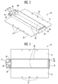
- FIG. 1 is a top view of a battery module cover according to an exemplary embodiment of the present invention
- FIG. 2 is a top perspective view of the battery module cover of FIG. 1 ;
- FIG. 3 is a bottom perspective view of the battery module cover of FIG. 1 ;
- FIG. 4 is a bottom view of the battery module cover of FIG. 1 ;
- FIG. 5 is a top view of a battery module cover according to another exemplary embodiment of the present invention.
- FIG. 6 is a top perspective view of the battery module cover of FIG. 5 ;
- FIG. 7 is a bottom perspective view of the battery module cover of FIG. 5 ;
- FIG. 8 is a bottom view of the battery module cover of FIG. 5 ;
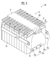
- FIG. 9 is a top perspective view of a battery module including the battery module cover of FIG. 5 ;
- FIG. 10 is a top perspective view of the battery module of FIG. 9 showing the battery module cover removed;
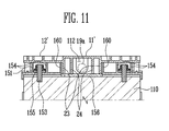
- FIG. 11 is a partial cross-sectional view of the battery module of FIG. 9 , taken along the line A-A';
- FIG. 12 is a schematic top perspective view of a battery pack in which a plurality of battery modules are connected according to an exemplary embodiment of the present invention.
- FIG. 1 is a top view of a battery module cover, or an integrated degassing cover, according to an exemplary embodiment of the present invention.
- FIGS. 2 and 3 are, respectively, a perspective view of a top side and a perspective view of a bottom side of the battery module cover shown in FIG. 1
- FIG. 4 is a bottom view of the battery module cover shown in FIG. 1 .
- a battery module cover 10 includes a degassing cover 11 assembled and mounted corresponding to a vent included in at least one battery cell, and a bus bar cover 12 assembled and mounted corresponding to an area where at least one bus bar is positioned.
- the degassing cover 11 is disposed on an upper part of the vent where the at least one battery cell is arranged and which is disposed in an upper part of each battery, and the bus bar cover 12 is formed to extend from opposite sides of the degassing cover 11 to cover an area where at least one bus bar connects electrodes of at least one battery cell to each other.
- the battery module cover 10 includes the degassing cover 11 and the bus bar cover 12 formed in an integrated manner, e.g. in a one-piece format, in order to decrease the number of components and to improve assembling efficiency.
- the battery module cover 10 includes an insertion hole 13 in at least one of the degassing cover 11 and the bus bar cover 12 to be coupled with an upper part of a battery module using a coupling component, such as a bolt.
- a plurality of the insertion holes 13 may be formed on one side of the bus bar cover 12.
- the degassing cover 11 is disposed on the upper part of the vent which is a discharge path of gas generated in the battery cell.
- An exhaust part 14 is formed to protrude at an outside lateral side of the degassing cover 11 to safely discharge gas discharged from the vent to the outside of the battery module. That is, the degassing cover 11 is securely fixed to the upper part of the vent, or when an insulating member, such as a gasket, is disposed on the upper part of the vent, the degassing cover 11 is securely fixed to an upper part of the insulating member, and thus a gas path is formed to enable gas discharged from the vent to be safely discharged in one direction. As shown in FIGS.
- the degassing cover 11 includes a first extension part 19 on a first side (e.g., a front side) where the exhaust part 14 protrudes, a second extension part 22 on a second side (e.g., a rear side) opposite to the first extension part 19, and a pair of first walls 23 extending between the first and second extension parts 19 and 22, each extending toward the vent of the battery cell.
- the degassing cover 11 comprises at least a first extension part 19, a second extension part 22, and a first pair of walls 23 formed to define a cavity, wherein said cavity is configured to cover vents of battery cells of a battery module.
- first and second extension parts 19 and 22 and the pair of first walls 23 are secured to the vent of the battery module or the insulating member disposed on the upper part of the vent, thereby forming a cavity, a space or path in which gas flows.
- An inside discharge hole 19a is formed in the first extension part 19, and the exhaust part 14 communicating with the inside discharge hole 19a protrudes outside the first extension part 19.
- gas generated in the battery cell and discharged from the vent accumulates in said cavity, passes through the inside discharge hole 19a in one direction along the path where the gas flows and is safely discharged to the outside through the exhaust part 14.
- the battery cell When the battery cell is repeatedly charged and discharged, the battery cell generally generates gas owing to byproducts of electrode plates and an electrolyte, and the gas may be discharged through the vent. Since gas discharged through the exhaust part 14 may damage a neighboring battery module or a neighboring battery cell, it is important to prevent or substantially prevent the gas from flowing to the neighboring battery module or the battery cell.
- the exhaust part 14 in one embodiment, has a shape in which a first member 14a extends in a parallel direction with the path of gas and has one closed end portion and a second member 14b extends on opposite sides of the first member 14a in a perpendicular direction to the first member 14a and has opposite end portions formed with outside discharge holes 15.
- the exhaust part 14 has a "T" shape formed of the first member 14a and the second member 14b formed to extend on the opposite sides of the first member 14a perpendicular to the first member 14a, and gas generated in the vent passes through the inside discharge hole 19a and is safely discharged to left and right sides parallel with an end plate through the outside discharge holes 15.
- the degassing cover 11 of the battery module cover 10 includes the first walls 23 formed to extend to the vent between the first and second extension parts 19 and 22.
- the first walls 23 are securely fixed to or secured against the upper part of the vent, or in an embodiment in which an insulating member, such as a gasket, is disposed on the upper part of the vent, the walls 23 are securely fixed to or secured against an upper part of the insulating member, and thus gas may flow in one direction.
- the battery module cover 10 further includes first and second accommodation walls 20 and 21 adjacent to the first and second extension parts 19 and 22, respectively, to be coupled and mounted with the end plate of the battery module. That is, in one embodiment, the first accommodation wall 20 and the second accommodation wall 21 are formed outside the degassing cover 11 of the battery module cover 10 adjacent to the first extension part 19 and the second extension part 22, respectively.
- a first accommodation space 25 is formed between the first extension part 19 and the first accommodation wall 20, and a second accommodation space 26 is formed between the second extension part 22 and the second accommodation wall 21.
- the first and second accommodation spaces 25 and 26, in one embodiment, are coupled with and receive the end plate.
- FIG. 5 is a top view of a battery module cover, or an integrated degassing cover, according to another exemplary embodiment of the present invention.
- FIGS. 6 and 7 are perspective views of a top side and a bottom side, respectively, of the battery module cover shown in FIG. 5
- FIG. 8 is a bottom view of the battery module cover shown in FIG. 5 .
- a bus bar cover 12' extending from opposite sides of a degassing cover 11' is formed to be thin, and one or more reinforcing members are formed to increase the strength of the bus bar cover 12'.
- a plurality of first levees, or ribs, 16 and a plurality of second levees, or ribs, 17 perpendicular to the first levees 16 are formed on the bus bar cover 12', and reinforcing protrusions 18 are formed at respective intersection portions of the first levees 16 and the second levees 17.
- the bus bar cover 12' has decreased thickness but has increased strength due to the first and second levees 16 and 17 and the reinforcing protrusions 18, so that an overall weight of a battery module may be reduced.
- the reinforcing members may have various configurations.
- first and second ribs may extend in directions that are not perpendicular to each another.
- the degassing cover 11' includes a first extension part 19 and a second extension part 22 which extend to a vent or an insulating member disposed on an upper part of the vent, and a pair of first walls 23 is formed to extend between the first extension part 19 and the second extension part 22, and a pair of second walls 24 is further formed between the first walls 23 to securely cover the vent or the insulating member disposed on the upper part of the vent. That is, in one embodiment, a plurality of layers of walls are formed on the degassing cover 11' to better prevent gas discharged through the vent from leaking to another side other than through an exhaust part 14. Further, while two pairs of walls (i.e. the first walls 23 and the second walls 24) are described above and shown in FIGS. 7 and 8 , in other embodiments, more or fewer walls may be formed depending on a size of the battery module and the vent and a number of vents in order to provide suitable sealing.
- a first accommodation wall 20 and a second accommodation wall 21 may be formed outside the degassing cover 11' of the battery module cover 10' adjacent to the first extension part 19 and the second extension part 22, respectively.
- a first accommodation space 25 is formed between the first extension part 19 and the first accommodation wall 20
- a second accommodation space 26 is formed between the second extension part 22 and the second accommodation wall 21.
- the second accommodation wall 21 adjacent to the second extension part 22 may have various shapes depending on a shape of an end plate of the battery module.
- the second accommodation wall 21 includes a protrusion 27 having a semicircular shape (see FIG. 7 ) for covering a connecting hole 112 (see FIG. 10 ) to facilitate coupling with a projection 111 (see FIG. 10 ) having the connecting hole 112 of the end plate and to prevent or substantially prevent leakage of gas through the connecting hole 112.
- FIG. 9 is a top perspective view of a battery module including a battery module cover according to an exemplary embodiment of the present invention.
- FIG. 10 is a top perspective view of the battery module showing the battery module cover removed, and
- FIG. 11 is a cross-sectional view, taken along the line A-A' of FIG. 9 .
- a battery module 100 includes a plurality of battery cells 101 arranged in a direction and including a vent 157; one or more insulating members 156 disposed in an area where the vents 157 are formed and including an opening corresponding to the vent 157; a housing 110 accommodating the battery cells 101; and the battery module cover 10' mounted on the battery cells 101, wherein the battery module cover 10' includes the degassing cover 11' and the bus bar cover 12' formed in an integrated form, e.g. in a one-piece format. While in one embodiment, the battery module 100 includes the battery module cover 10', in another embodiment, the battery module 100 may include the battery module cover 10.
- the battery cells 101 are lithium ion secondary batteries having a polygonal shape, as an illustrative example.
- embodiments of the battery module 100 are not limited thereto and, in other embodiments, may include battery cells of different materials and/or configurations. That is, embodiments of the present invention may be applied to various types of batteries, such as a lithium polymer battery or a cylindrical battery.
- the battery cells 101 may include a battery case having an opening and a cap plate covering the opening.
- the battery case accommodates an electrode assembly including a positive plate, a negative plate, a separator interposed between the plates, and an electrolyte.
- a positive terminal 153 connected to the positive plate and a negative terminal 153' connected to the negative plate are formed to protrude to the outside on opposite ends of the cap plate, and the positive terminal 153 and the negative terminal 153' may be electrically connected by a bus bar 155.
- the positive plate and the negative plate of the electrode assembly react with the electrolyte to generate energy, and the energy is transmitted to the outside through the positive terminal 153 and the negative terminal 153'.
- a positive terminal 153 and a negative terminal 153' of two neighboring battery cells 101 may be electrically connected through the bus bar 155 formed of nickel or the like.
- a blocking wall 154 is formed to surround the pair of positive and negative terminals 153 and 153' connected via the bus bar 155, thereby preventing or substantially preventing a short circuit between adjacent ones of the terminals 153, 153'.
- a fixing member 151 is formed at one side of the blocking wall 154 to fix a coupling component 152, such as a bolt, inserted into an insertion hole 13 of the battery module cover 10'.
- the vent 157 is formed between the positive terminal 153 and the negative terminal 153'.
- the vent 157 may function as a path through which the gas is discharged out of the battery cells 101 to prevent the battery cells 101 from being destroyed due to internal pressure.
- the plurality of battery cells 101 are arranged in a first direction, and the battery cells 101 are arranged side by side so that large front sides of the battery cells 101 face each other.
- the vents 157 are disposed at center portions of the respective battery cells 101, and the vents 157 are arranged approximately in a straight line along the battery cells 101.
- the insulating member 156 such as a gasket, including an opening is positioned on each vent 157.
- the insulating member 156 is arranged in each battery cell 101 so that the opening is disposed corresponding to the vent 157.
- a levee, or rib, 158 may be formed between the insulating members 156 to position the insulating member 156 with respect to the vent 157.
- a pair of isolation layers 160 may be formed on opposite sides of the insulating members 156 to support the battery module cover 10' from a bottom side thereof.
- the pair of isolation layers 160 supports the battery module cover 10' from the bottom and guides the degassing cover 11' and the bus bar cover 12' of the battery module cover 10' to a mounted position.
- the insulating members 156 are disposed between the pair of the isolation layers 160 to allow the insulating members 156 to be easily positioned.
- the isolation layers 160, the blocking wall 154 surrounding the bus bar 155 to connect neighboring terminals 153, 153', and the fixing member 151 formed at one side of the blocking wall 154 may be integrated to constitute an upper cover 150, thereby improving efficiency in assembling the battery module 100.
- the housing 110 in one embodiment, includes a pair of end plates 120 spaced apart from each other in one direction (e.g., the first direction), a lateral side connecting member 130 connecting lateral sides of the end plates 120, and a bottom plate 140 connecting bottom sides of the end plates 120.
- the plurality of battery cells 101 are accommodated between the pair of end plates 120, and the end plates 120 are disposed to be in contact with an outer side of each outermost battery 101 and press the battery cells 101 inward.
- the lateral side connecting member 130 is connected to one end and to another end of the end plates 120 to support opposite sides of the battery cells 101.
- a bottom side of the battery cells 101 may be supported by the bottom plate 140, in which opposite ends of the bottom plate 140 are connected to the end plates 120.
- the plurality of battery cells 101 supported by the end plates 120, the lateral side connecting member 130, and the bottom plate 140 may be arranged therein so that positive terminals 153 and negative terminals 153' are disposed alternately and may be connected in series using the bas bar 155.
- a positive terminal 153 or a negative terminal 153' of the outermost battery cell 101 may be used as a high current terminal.
- a connection structure and a number of battery cells 101 may be modified depending on a design of the battery module 100.
- the integrated battery module cover 10, 10' is mounted on the insulating member 156, such as a gasket, and the bus bar 155.
- the battery module cover 10, 10' includes the degassing cover 11, 11' and the bus bar cover 12, 12' in an integrated form and is mounted on the insulating member 156 and the bus bar 155.
- the degassing cover 11, 11' of the battery module cover 10, 10' has at least one pair of the walls 23 and 24 extending from a lower part (e.g., a bottom side) and sealing an upper part of the insulating member 156.
- a sealed space is formed between the insulating member 156 and the first walls 23 to provide a path for gas discharged from the vent 157.
- the pair of second walls 24 is formed, in addition, inside the first walls 23 to more thoroughly prevent gas from leaking from the sealed space to the outside.
- a path for discharged gas is formed between the degassing cover 11, 11' of the battery module cover 10, 10' and the insulating member 156, and the gas discharged from the vents 157 flows to the inside discharge hole 19a formed in the first extension part 19 of the degassing cover 11, 11' and then is discharged to the outside through at least one external discharge hole 15 of the exhaust part 14 protruding on an external lateral side of the degassing cover 11, 11'.
- the exhaust part 14 in one embodiment, has a "T" shape in which a first member 14a extends in a direction parallel with the path of gas, and a second member 14b extends on opposite sides of the first member 14a in a direction perpendicular to the first member 14a and has opposite end portions formed with the outside discharge holes 15. If gas discharged from the battery cell 101 flows to an adjacent battery cell 101 or an adjacent battery module 100, the gas may damage the adjacent battery cell 101 or the adjacent battery module 100. Thus, the path of gas is formed in a direction parallel with the end plates 120 to safely discharge the gas to the outside.
- the exhaust part 14 is formed to have a "T" shape constituted by the first member 14a and the second member 14b formed to extend on the opposite sides of the first member 14a perpendicular to the first member 14a, so that gas discharged through the exhaust part 14 may be discharged to left and right sides parallel with the end plates 120.
- the battery module 100 may be used as part of a plurality of connected battery modules 100 for providing high power.
- the plurality of battery modules 100 in the set may be connected so that end plates 120 of neighboring battery modules 100 face each other. Further, a space between neighboring battery modules 100 is formed to be small in order to reduce a volume of the plurality of battery modules 100.
- the exhaust part 14 of the battery module cover 10, 10' is formed in a "T" shape, gas discharged through the exhaust part 14 is discharged separately to left and right sides parallel with the end plates 120, and thus the gas does not adversely affect an adjacent battery module 100.
- FIG. 11 is a cross-sectional view taken along the line A-A' of FIG. 9 .
- a width of the insulating member 156 may be greater than a distance between the first walls 23 of the battery module cover 10, 10' or a distance between the second walls 24 of the battery module cover 10, 10' to improve sealing ability.
- the projection 111 including the coupling hole 112 is formed in an upper part of one end plate 120 of the battery module 100 to be received in the first accommodation space 25 between the first extension part 19 and the first accommodation wall 20 of the degassing cover 11, 11'.
- a projection 111 including a coupling hole 112 in an upper part of the other end plate 120 is received in the second accommodation space 26 formed between the second extension part 21 and the second accommodation wall 22 of the degassing cover 11, 11'.
- the projection 111 includes the coupling hole 112 connected to the inside discharge hole 19a formed in the first extension part 19 of the degassing cover 11, 11', and thus gas discharged from the vent 157 may be discharged through the outside discharge hole 15 via the coupling hole 112.
- the gas discharged through the vent 157 is discharged in one direction through the exhaust part 14 of the degassing cover 11, 11' of the battery module cover 10, 10', the gas is prevented or substantially prevented from leaking through the coupling hole 112 of the projection 111 to the second extension part 21 or the second accommodation wall 22 of the degassing cover 11, 11' where the exhaust part 14 is not formed.
- the protrusion 27 which has a semicircular shape and covers the connecting hole 112 may be formed on the second accommodation wall 22 or the second extension part 21 to facilitate coupling with the projection 111 having the connecting hole 112 of the other end plate 120 and to prevent or substantially prevent leakage of gas through the connecting hole 112.
- FIG. 12 is a schematic perspective view of a battery pack 200 in which a plurality of battery modules 100 are connected according to another exemplary embodiment of the present invention.
- a plurality of the battery modules 100 are arranged and manufactured into the battery pack 200.
- the T-shaped exhaust part 14 of the battery module cover 10, 10' may be connected to another T-shaped exhaust part 14 of a neighboring battery module 100 using a flexible communication pipe 30 or other suitable connection member.
- gas generated in the vent flows in the degassing cover 11, 11' of the battery module cover 10, 10' in one direction and then is discharged to the exhaust part 14 protruding on an outside of the degassing cover 11, 11'.
- the gas flows through the flexible communication pipe 30 connecting the outside discharge hole 15 of the exhaust part 14 to an outside discharge hole 15 of the exhaust part 14 of a neighboring battery module 100.
- the gas travels to right and left sides of the end plates 120 and in a parallel direction with the end plates 120, thereby leading the gas in a direction so that the gas does not damage an adjacent battery module 100 or an adjacent battery cell 101.
Abstract
Description
- Aspects of embodiments of the present invention relate to a battery module having a plurality of battery cells.
- Recently, a high-output battery module using a non-aqueous electrolyte having a high energy density has been developed. The high-output battery module is formed to have high capacity by constituting a plurality of battery cells connected in series so that the battery module may be used to drive a motor of a device using high power, such as an electric vehicle.
- A battery cell includes an electrode assembly constituted by a positive plate and a negative plate, and an electrolyte, and generates energy by an electrochemical reaction of the plates with the electrolyte. Here, gas may be generated in the battery cell due to a side reaction of the electrochemical reaction. Thus, a path or a vent for the gas may be formed in the battery module in order to efficiently treat the gas generated in a plurality of battery cells.
- The present invention is directed to the battery module cover, the battery module and the battery pack as defined in the claims and/or as disclosed below.
- The battery module cover of the invention comprises a degassing cover comprising:
- at least a first extension part, a second extension part and a first pair of walls extending from a first surface of the degassing cover and defining a cavity, wherein the cavity is configured to cover vents of battery cells of a battery module; and
- an exhaust part extending from an end of the degassing cover, the first extension part having an inside discharge hole formed between the cavity and the exhaust part; and
- a bus bar cover comprising a first bus bar cover portion extending from a first side of the degassing cover, and a second bus bar cover portion extending from a second side of the degassing cover opposite the first side.
- a plurality of battery cells arranged in a first direction from a first end of the battery module to a second end of the battery module, each of the battery cells comprising:
- a case including a vent;
- an electrode assembly housed in the case; and
- a terminal electrically coupled to the electrode assembly;
- a bus bar coupled between the terminals of adjacent battery cells of the plurality of battery cells; and
- a battery module cover of the invention covering the plurality of battery cells. The battery module may further comprise insulating members adjacent to the vents, wherein at least one of the first extension part, the second extension part and/or the first pair of walls extending from a first surface of the degassing cover contacts the insulating member.
- a pair of end plates contacting outermost battery cells of the plurality of battery cells at the first and second ends of the battery module; and
- a connecting member extending in the first direction and coupling the end plates to each other.
- a plurality of battery modules of the invention arranged in a row and each comprising:
- a plurality of battery cells; and
- a battery module cover of the invention covering the plurality of battery cells,
- a pair of second members extending from the first member in directions perpendicular to the first member and opposite each other, the second members having outside discharge holes at ends thereof, and
wherein the battery pack of the invention further comprises a communication pipe extending between respective outside discharge holes of the exhaust parts of adjacent battery modules. - In addition the present invention is also directed to the following aspects and embodiments.
- According to an aspect of embodiments of the present invention, a battery module cover improves assembly of a plurality of battery cells.
- Further, according to another aspect of embodiments of the present invention, a battery module has a structure for reliably preventing or reducing leakage of gas generated in a plurality of battery cells.
- According to an embodiment of the present invention, a battery module includes: a plurality of battery cells arranged in a first direction from a first end of the battery module to a second end of the battery module, each of the battery cells including a case including a vent, an electrode assembly housed in the case, and a terminal electrically coupled to the electrode assembly; a bus bar coupled between the terminals of adjacent battery cells of the plurality of battery cells; and a battery module cover covering the plurality of battery cells and including a degassing cover covering the vents of the plurality of battery cells, and a bus bar cover covering the terminals of the plurality of battery cells and the bus bar.
- The degassing cover and the bus bar cover may be integrally formed. In one embodiment, the degassing cover includes at least one protrusion extending from a surface of the degassing cover facing the plurality of battery cells, the at least one protrusion defining a cavity covering the vents of the plurality of battery cells. In one embodiment, the degassing cover further includes an exhaust part extending from the degassing cover at the first end of the battery module, and the at least one protrusion has an opening between the cavity and the exhaust part. The exhaust part may include a first exhaust portion extending from the degassing cover; and at least one second exhaust portion extending from the first exhaust portion in a direction perpendicular to the first exhaust portion, the at least one second exhaust portion having an exhaust opening at an end thereof.
- In one embodiment, a battery module further includes sealing members adjacent the vents, and the at least one protrusion contacts the sealing members. In one embodiment, the at least one protrusion includes a first pair of ribs extending in the first direction and a second pair of ribs between the first pair of ribs and extending in the first direction.
- In one embodiment, a battery module further includes a housing receiving the plurality of battery cells, the housing including a pair of end plates contacting outermost battery cells of the plurality of battery cells at the first and second ends of the battery module; and a connecting member extending in the first direction and coupling the end plates to each other. An end plate of the pair of end plates may include a projection extending toward the battery module cover and having an opening formed therein, the opening receiving an exhaust part extending from the degassing cover at the first end of the battery module. The battery module cover may have an accommodation space at at least one of the first and second ends of the battery module and spaced apart from the cavity, and the projection of the end plate may be received in the accommodation space.
- The battery module cover may include a plurality of ribs intersecting one another at reinforcing portions on a surface of the battery module cover. In one embodiment, the bus bar cover includes a first bus bar cover portion extending from a side of the degassing cover; and a second bus bar cover portion extending from an opposite side of the degassing cover.
- In one embodiment, a battery module further includes a cover assembly mounted between the plurality of battery cells and the battery module cover, the cover assembly including at least one coupling member coupling the battery module cover to the plurality of battery cells. The cover assembly may further include a pair of support members extending toward the battery module cover and along the first direction on opposite sides of the vents, wherein the support members support the battery module cover.
- According to another embodiment of the present invention, a battery module cover includes: a degassing cover including at least one protrusion extending from a first surface of the degassing cover, the at least one protrusion defining a cavity, and an exhaust part extending from an end of the degassing cover, the at least one protrusion having an opening between the cavity and the exhaust part; and a bus bar cover including a first bus bar cover portion extending from a first side of the degassing cover, and a second bus bar cover portion extending from a second side of the degassing cover opposite the first side.
- The degassing cover and the bus bar cover may be integrally formed. In one embodiment, the exhaust part includes a first exhaust portion extending from the degassing cover; and a pair of second exhaust portions extending from the first exhaust portion in directions perpendicular to the first exhaust portion and opposite each other, the second exhaust portions having exhaust openings at ends thereof. The bus bar cover may further include a plurality of ribs intersecting one another at reinforcing portions on a surface of the bus bar cover.
- According to another embodiment of the present invention, a battery pack includes: a plurality of battery modules arranged in a row and each including a plurality of battery cells arranged in a first direction from a first end of the battery module to a second end of the battery module, each of the battery cells including a case including a vent, an electrode assembly housed in the case, and a terminal electrically coupled to the electrode assembly; a bus bar coupled between the terminals of adjacent battery cells of the plurality of battery cells; and a battery module cover covering the plurality of battery cells and including a degassing cover covering the vents of the plurality of battery cells and including an exhaust part at the first end of the battery module; and a bus bar cover covering the terminals of the plurality of battery cells and the bus bar, and the exhaust parts of adjacent battery modules of the plurality of battery modules are connected to one another.
- In one embodiment, the exhaust part includes a first exhaust portion extending from the degassing cover; and a pair of second exhaust portions extending from the first exhaust portion in directions perpendicular to the first exhaust portion and opposite each other, the second exhaust portions having exhaust openings at ends thereof, and the battery pack further includes a connection member extending between respective exhaust openings of the adjacent battery modules.
- According to another embodiment of the present invention, a battery module includes a pair of end plates; at least one battery cell arranged in one direction between the pair of end plates; a connecting member to connect the pair of end plates; and a battery module cover to cover an upper part of the at least one battery cell, the battery module cover including a degassing cover corresponding to a vent of the battery cell and a bus bar cover extending from the degassing cover to opposite sides and formed integrated, and the degassing cover including an exhaust part protruding therefrom.
- The degassing cover of the battery module cover may seal the vent of the battery cell or an insulating member disposed on the vent to form an inside space where gas flows.
- The degassing cover may include a first extension part and a second extension part which extend parallel with the pair of end plates to the vent of the battery cell, wherein an inside discharge hole is formed in one of the first extension part and the second extension part, and an exhaust part communicating with the inside discharge hole is formed to protrude on an outside of one of the first extension part and the second extension part.
- Further, the degassing cover may include at least one pair of walls closely disposed to the bent or the insulating member disposed on the vent to form a path of gas, wherein the pair of walls is formed to extend between the first extension part and the second extension part.
- The walls may include a pair of first walls and a pair of second walls disposed inside the first walls.
- The exhaust part formed to protrude on an outside of the degassing cover may have a "T" shape in which a first member has one closed end portion and a second member extends on opposite sides of the first member in a perpendicular direction to the first member and in a parallel direction with the end plates and has each end portion formed with an outside discharge hole.
- The bus bar cover may include at least one insertion hole into which a coupling component for coupling with the battery module is inserted.
- A first accommodation wall and a second accommodation wall may be formed adjacently to the first extension part and the second extension part, respectively, a first accommodation space may be formed between the first extension part and the first accommodation wall, and a second accommodation space may be formed between the second extension part and the second accommodation wall.
- A projection formed on the pair of end plates may be inserted into the first accommodation space and the second accommodation space.
- The projection inserted into the first accommodation space may include a coupling hole communicating with the inside discharge hole formed in the first extension part.
- According to another aspect of the present invention, a bus bar cover of a battery module cover includes a plurality of first levees, a plurality of second levees perpendicular to the first levees, and a reinforced protrusion formed on an intersection portion of the first levees and the second levees.
- The insulating member disposed on the vent of the battery cell may be formed to be larger than the plurality of walls.
- The battery module may include a bus bar connecting terminals of the respective battery cells, wherein the bus bar may be isolated from an adjacent bus bar, and each bus bar may be surrounded by a blocking wall.
- A pair of isolation layers may be formed on opposite sides of the vent or the insulating member disposed on the vent to support the battery module cover from a bottom.
- A fixing member may be formed on one side of the blocking wall to fix the coupling component inserted into the insertion hole.
- The blocking wall, the pair of isolation layers, and the fixing member may be formed to constitute an upper cover in an integrated form.
- According to still another embodiment of the present invention, a battery pack includes a plurality of battery modules arranged in a row; a battery module cover covering the respective battery modules and including a degassing cover and a bus bar cover formed in an integrated form; a T-shaped exhaust part formed to protrude on the degassing cover; and a communicating member (e.g., a pipe) connecting outside discharge holes formed in the exhaust part to each other.
- As described above, according to an aspect of exemplary embodiments of the present invention, a battery module uses fewer components in assembling a plurality of battery cells and improves assembling efficiency, so that productivity of the battery module is enhanced.
- Further, according to another aspect of exemplary embodiments of the present invention, a battery module prevents or reduces leakage of gas to improve sealing ability.
- The accompanying drawings, together with the specification, illustrate some exemplary embodiments of the present invention, and, together with the description, serve to explain the principles of the present invention.
-
FIG. 1 is a top view of a battery module cover according to an exemplary embodiment of the present invention; -
FIG. 2 is a top perspective view of the battery module cover ofFIG. 1 ; -
FIG. 3 is a bottom perspective view of the battery module cover ofFIG. 1 ; -
FIG. 4 is a bottom view of the battery module cover ofFIG. 1 ; -
FIG. 5 is a top view of a battery module cover according to another exemplary embodiment of the present invention; -
FIG. 6 is a top perspective view of the battery module cover ofFIG. 5 ; -
FIG. 7 is a bottom perspective view of the battery module cover ofFIG. 5 ; -
FIG. 8 is a bottom view of the battery module cover ofFIG. 5 ; -
FIG. 9 is a top perspective view of a battery module including the battery module cover ofFIG. 5 ; -
FIG. 10 is a top perspective view of the battery module ofFIG. 9 showing the battery module cover removed; -
FIG. 11 is a partial cross-sectional view of the battery module ofFIG. 9 , taken along the line A-A'; and -
FIG. 12 is a schematic top perspective view of a battery pack in which a plurality of battery modules are connected according to an exemplary embodiment of the present invention. - Reference will now be made in detail to some exemplary embodiments of the present invention, examples of which are illustrated in the accompanying drawings. These exemplary embodiments are described below in order to explain aspects of the present invention with reference to the exemplary embodiments shown in the drawings. The present invention may, however, be embodied in many different forms and should not be construed as limited to the exemplary embodiments set forth herein. Rather, these exemplary embodiments are provided in order to convey the scope of the invention to those skilled in the art. In the drawings, like reference numerals refer to like elements throughout, and the size and relative sizes of layers and regions may be exaggerated for clarity.
-
FIG. 1 is a top view of a battery module cover, or an integrated degassing cover, according to an exemplary embodiment of the present invention.FIGS. 2 and3 are, respectively, a perspective view of a top side and a perspective view of a bottom side of the battery module cover shown inFIG. 1 , andFIG. 4 is a bottom view of the battery module cover shown inFIG. 1 . - Referring to
FIGS. 1 to 4 , abattery module cover 10 according to an exemplary embodiment of the present invention includes adegassing cover 11 assembled and mounted corresponding to a vent included in at least one battery cell, and abus bar cover 12 assembled and mounted corresponding to an area where at least one bus bar is positioned. Thedegassing cover 11 is disposed on an upper part of the vent where the at least one battery cell is arranged and which is disposed in an upper part of each battery, and thebus bar cover 12 is formed to extend from opposite sides of thedegassing cover 11 to cover an area where at least one bus bar connects electrodes of at least one battery cell to each other. While according to a conventional method, a degassing cover and a bus bar cover are separately mounted, thebattery module cover 10 according to the present embodiment includes thedegassing cover 11 and thebus bar cover 12 formed in an integrated manner, e.g. in a one-piece format, in order to decrease the number of components and to improve assembling efficiency. - In one embodiment, the
battery module cover 10 includes aninsertion hole 13 in at least one of thedegassing cover 11 and thebus bar cover 12 to be coupled with an upper part of a battery module using a coupling component, such as a bolt. A plurality of the insertion holes 13 may be formed on one side of thebus bar cover 12. - The
degassing cover 11 is disposed on the upper part of the vent which is a discharge path of gas generated in the battery cell. Anexhaust part 14 is formed to protrude at an outside lateral side of thedegassing cover 11 to safely discharge gas discharged from the vent to the outside of the battery module. That is, thedegassing cover 11 is securely fixed to the upper part of the vent, or when an insulating member, such as a gasket, is disposed on the upper part of the vent, thedegassing cover 11 is securely fixed to an upper part of the insulating member, and thus a gas path is formed to enable gas discharged from the vent to be safely discharged in one direction.
As shown inFIGS. 3 and 4 , in one embodiment, thedegassing cover 11 includes afirst extension part 19 on a first side (e.g., a front side) where theexhaust part 14 protrudes, asecond extension part 22 on a second side (e.g., a rear side) opposite to thefirst extension part 19, and a pair offirst walls 23 extending between the first andsecond extension parts degassing cover 11 comprises at least afirst extension part 19, asecond extension part 22, and a first pair ofwalls 23 formed to define a cavity, wherein said cavity is configured to cover vents of battery cells of a battery module. Thus, the first andsecond extension parts first walls 23 are secured to the vent of the battery module or the insulating member disposed on the upper part of the vent, thereby forming a cavity, a space or path in which gas flows. Aninside discharge hole 19a is formed in thefirst extension part 19, and theexhaust part 14 communicating with theinside discharge hole 19a protrudes outside thefirst extension part 19. Thus, gas generated in the battery cell and discharged from the vent accumulates in said cavity, passes through theinside discharge hole 19a in one direction along the path where the gas flows and is safely discharged to the outside through theexhaust part 14. - When the battery cell is repeatedly charged and discharged, the battery cell generally generates gas owing to byproducts of electrode plates and an electrolyte, and the gas may be discharged through the vent. Since gas discharged through the
exhaust part 14 may damage a neighboring battery module or a neighboring battery cell, it is important to prevent or substantially prevent the gas from flowing to the neighboring battery module or the battery cell. Thus, theexhaust part 14, in one embodiment, has a shape in which afirst member 14a extends in a parallel direction with the path of gas and has one closed end portion and asecond member 14b extends on opposite sides of thefirst member 14a in a perpendicular direction to thefirst member 14a and has opposite end portions formed with outside discharge holes 15. That is, in one embodiment, theexhaust part 14 has a "T" shape formed of thefirst member 14a and thesecond member 14b formed to extend on the opposite sides of thefirst member 14a perpendicular to thefirst member 14a, and gas generated in the vent passes through theinside discharge hole 19a and is safely discharged to left and right sides parallel with an end plate through the outside discharge holes 15. - As described above, the
degassing cover 11 of thebattery module cover 10 according to one embodiment includes thefirst walls 23 formed to extend to the vent between the first andsecond extension parts first walls 23 are securely fixed to or secured against the upper part of the vent, or in an embodiment in which an insulating member, such as a gasket, is disposed on the upper part of the vent, thewalls 23 are securely fixed to or secured against an upper part of the insulating member, and thus gas may flow in one direction. - As shown in
FIGS. 3 and 4 , in one embodiment, thebattery module cover 10 further includes first andsecond accommodation walls second extension parts first accommodation wall 20 and thesecond accommodation wall 21 are formed outside thedegassing cover 11 of thebattery module cover 10 adjacent to thefirst extension part 19 and thesecond extension part 22, respectively. Here, afirst accommodation space 25 is formed between thefirst extension part 19 and thefirst accommodation wall 20, and asecond accommodation space 26 is formed between thesecond extension part 22 and thesecond accommodation wall 21. The first andsecond accommodation spaces -
FIG. 5 is a top view of a battery module cover, or an integrated degassing cover, according to another exemplary embodiment of the present invention.FIGS. 6 and7 are perspective views of a top side and a bottom side, respectively, of the battery module cover shown inFIG. 5 , andFIG. 8 is a bottom view of the battery module cover shown inFIG. 5 . - As shown in
FIGS. 5 and 6 , in a battery module cover 10' according to another exemplary embodiment, abus bar cover 12' extending from opposite sides of a degassing cover 11' is formed to be thin, and one or more reinforcing members are formed to increase the strength of thebus bar cover 12'. In one embodiment, a plurality of first levees, or ribs, 16 and a plurality of second levees, or ribs, 17 perpendicular to thefirst levees 16 are formed on thebus bar cover 12', and reinforcingprotrusions 18 are formed at respective intersection portions of thefirst levees 16 and thesecond levees 17. Accordingly, thebus bar cover 12' has decreased thickness but has increased strength due to the first andsecond levees protrusions 18, so that an overall weight of a battery module may be reduced. In other embodiments, the reinforcing members may have various configurations. For example, in one embodiment, first and second ribs may extend in directions that are not perpendicular to each another. - Referring to
FIGS. 7 and 8 , the degassing cover 11' includes afirst extension part 19 and asecond extension part 22 which extend to a vent or an insulating member disposed on an upper part of the vent, and a pair offirst walls 23 is formed to extend between thefirst extension part 19 and thesecond extension part 22, and a pair ofsecond walls 24 is further formed between thefirst walls 23 to securely cover the vent or the insulating member disposed on the upper part of the vent. That is, in one embodiment, a plurality of layers of walls are formed on the degassing cover 11' to better prevent gas discharged through the vent from leaking to another side other than through anexhaust part 14. Further, while two pairs of walls (i.e. thefirst walls 23 and the second walls 24) are described above and shown inFIGS. 7 and 8 , in other embodiments, more or fewer walls may be formed depending on a size of the battery module and the vent and a number of vents in order to provide suitable sealing. - Referring to
FIGS. 7 and 8 , afirst accommodation wall 20 and asecond accommodation wall 21 may be formed outside the degassing cover 11' of the battery module cover 10' adjacent to thefirst extension part 19 and thesecond extension part 22, respectively. Here, afirst accommodation space 25 is formed between thefirst extension part 19 and thefirst accommodation wall 20, and asecond accommodation space 26 is formed between thesecond extension part 22 and thesecond accommodation wall 21. Here, thesecond accommodation wall 21 adjacent to thesecond extension part 22 may have various shapes depending on a shape of an end plate of the battery module. In one embodiment, thesecond accommodation wall 21 includes aprotrusion 27 having a semicircular shape (seeFIG. 7 ) for covering a connecting hole 112 (seeFIG. 10 ) to facilitate coupling with a projection 111 (seeFIG. 10 ) having the connectinghole 112 of the end plate and to prevent or substantially prevent leakage of gas through the connectinghole 112. -
FIG. 9 is a top perspective view of a battery module including a battery module cover according to an exemplary embodiment of the present invention.FIG. 10 is a top perspective view of the battery module showing the battery module cover removed, andFIG. 11 is a cross-sectional view, taken along the line A-A' ofFIG. 9 . - Referring to
FIGS. 9 and10 , abattery module 100 according to an embodiment of the present invention includes a plurality ofbattery cells 101 arranged in a direction and including avent 157; one or moreinsulating members 156 disposed in an area where thevents 157 are formed and including an opening corresponding to thevent 157; ahousing 110 accommodating thebattery cells 101; and the battery module cover 10' mounted on thebattery cells 101, wherein the battery module cover 10' includes the degassing cover 11' and thebus bar cover 12' formed in an integrated form, e.g. in a one-piece format. While in one embodiment, thebattery module 100 includes the battery module cover 10', in another embodiment, thebattery module 100 may include thebattery module cover 10. - In one embodiment, the
battery cells 101 are lithium ion secondary batteries having a polygonal shape, as an illustrative example. However, embodiments of thebattery module 100 are not limited thereto and, in other embodiments, may include battery cells of different materials and/or configurations. That is, embodiments of the present invention may be applied to various types of batteries, such as a lithium polymer battery or a cylindrical battery. - The
battery cells 101 may include a battery case having an opening and a cap plate covering the opening. The battery case accommodates an electrode assembly including a positive plate, a negative plate, a separator interposed between the plates, and an electrolyte. In one embodiment, apositive terminal 153 connected to the positive plate and a negative terminal 153' connected to the negative plate are formed to protrude to the outside on opposite ends of the cap plate, and thepositive terminal 153 and the negative terminal 153' may be electrically connected by abus bar 155. The positive plate and the negative plate of the electrode assembly react with the electrolyte to generate energy, and the energy is transmitted to the outside through thepositive terminal 153 and the negative terminal 153'. Apositive terminal 153 and a negative terminal 153' of two neighboringbattery cells 101 may be electrically connected through thebus bar 155 formed of nickel or the like. In one embodiment, a blockingwall 154 is formed to surround the pair of positive andnegative terminals 153 and 153' connected via thebus bar 155, thereby preventing or substantially preventing a short circuit between adjacent ones of theterminals 153, 153'. In one embodiment, a fixingmember 151 is formed at one side of the blockingwall 154 to fix acoupling component 152, such as a bolt, inserted into aninsertion hole 13 of the battery module cover 10'. - In one embodiment, the
vent 157 is formed between thepositive terminal 153 and the negative terminal 153'. When gas generated in thebattery cells 101 has a pressure of a predetermined amount or greater, thevent 157 may function as a path through which the gas is discharged out of thebattery cells 101 to prevent thebattery cells 101 from being destroyed due to internal pressure. In one embodiment, the plurality ofbattery cells 101 are arranged in a first direction, and thebattery cells 101 are arranged side by side so that large front sides of thebattery cells 101 face each other. In one embodiment, thevents 157 are disposed at center portions of therespective battery cells 101, and thevents 157 are arranged approximately in a straight line along thebattery cells 101. In one embodiment, the insulatingmember 156, such as a gasket, including an opening is positioned on eachvent 157. The insulatingmember 156 is arranged in eachbattery cell 101 so that the opening is disposed corresponding to thevent 157. A levee, or rib, 158 may be formed between the insulatingmembers 156 to position the insulatingmember 156 with respect to thevent 157. - A pair of isolation layers 160 may be formed on opposite sides of the insulating
members 156 to support the battery module cover 10' from a bottom side thereof. In one embodiment, the pair of isolation layers 160 supports the battery module cover 10' from the bottom and guides the degassing cover 11' and thebus bar cover 12' of the battery module cover 10' to a mounted position. Further, the insulatingmembers 156 are disposed between the pair of the isolation layers 160 to allow the insulatingmembers 156 to be easily positioned. - In one embodiment, the isolation layers 160, the blocking
wall 154 surrounding thebus bar 155 to connect neighboringterminals 153, 153', and the fixingmember 151 formed at one side of the blockingwall 154 may be integrated to constitute anupper cover 150, thereby improving efficiency in assembling thebattery module 100. - The
housing 110, in one embodiment, includes a pair ofend plates 120 spaced apart from each other in one direction (e.g., the first direction), a lateralside connecting member 130 connecting lateral sides of theend plates 120, and abottom plate 140 connecting bottom sides of theend plates 120. In one embodiment, the plurality ofbattery cells 101 are accommodated between the pair ofend plates 120, and theend plates 120 are disposed to be in contact with an outer side of eachoutermost battery 101 and press thebattery cells 101 inward. The lateralside connecting member 130 is connected to one end and to another end of theend plates 120 to support opposite sides of thebattery cells 101. A bottom side of thebattery cells 101 may be supported by thebottom plate 140, in which opposite ends of thebottom plate 140 are connected to theend plates 120. - The plurality of
battery cells 101 supported by theend plates 120, the lateralside connecting member 130, and thebottom plate 140 may be arranged therein so thatpositive terminals 153 and negative terminals 153' are disposed alternately and may be connected in series using the bas bar 155. Apositive terminal 153 or a negative terminal 153' of theoutermost battery cell 101 may be used as a high current terminal. In embodiments of the present invention, a connection structure and a number ofbattery cells 101 may be modified depending on a design of thebattery module 100. - In one embodiment, the integrated
battery module cover 10, 10' is mounted on the insulatingmember 156, such as a gasket, and thebus bar 155. As described above, in one embodiment, thebattery module cover 10, 10' includes thedegassing cover 11, 11' and thebus bar cover member 156 and thebus bar 155. Thedegassing cover 11, 11' of thebattery module cover 10, 10' has at least one pair of thewalls member 156. Thus, a sealed space is formed between the insulatingmember 156 and thefirst walls 23 to provide a path for gas discharged from thevent 157. In one embodiment, the pair ofsecond walls 24 is formed, in addition, inside thefirst walls 23 to more thoroughly prevent gas from leaking from the sealed space to the outside. A path for discharged gas is formed between the degassingcover 11, 11' of thebattery module cover 10, 10' and the insulatingmember 156, and the gas discharged from thevents 157 flows to theinside discharge hole 19a formed in thefirst extension part 19 of thedegassing cover 11, 11' and then is discharged to the outside through at least oneexternal discharge hole 15 of theexhaust part 14 protruding on an external lateral side of thedegassing cover 11, 11'. - As described above, the
exhaust part 14, in one embodiment, has a "T" shape in which afirst member 14a extends in a direction parallel with the path of gas, and asecond member 14b extends on opposite sides of thefirst member 14a in a direction perpendicular to thefirst member 14a and has opposite end portions formed with the outside discharge holes 15. If gas discharged from thebattery cell 101 flows to anadjacent battery cell 101 or anadjacent battery module 100, the gas may damage theadjacent battery cell 101 or theadjacent battery module 100. Thus, the path of gas is formed in a direction parallel with theend plates 120 to safely discharge the gas to the outside. That is, it is important to safely discharge the gas discharged through thevent 157 to the outside through theexhaust part 14 formed on one side of thedegassing cover 11, 11' of thebattery module cover 10, 10'. Thus, in one embodiment, theexhaust part 14 is formed to have a "T" shape constituted by thefirst member 14a and thesecond member 14b formed to extend on the opposite sides of thefirst member 14a perpendicular to thefirst member 14a, so that gas discharged through theexhaust part 14 may be discharged to left and right sides parallel with theend plates 120. - The
battery module 100 may be used as part of a plurality of connectedbattery modules 100 for providing high power. The plurality ofbattery modules 100 in the set may be connected so thatend plates 120 of neighboringbattery modules 100 face each other. Further, a space between neighboringbattery modules 100 is formed to be small in order to reduce a volume of the plurality ofbattery modules 100. In one embodiment, since theexhaust part 14 of thebattery module cover 10, 10' is formed in a "T" shape, gas discharged through theexhaust part 14 is discharged separately to left and right sides parallel with theend plates 120, and thus the gas does not adversely affect anadjacent battery module 100. -
FIG. 11 is a cross-sectional view taken along the line A-A' ofFIG. 9 . In thebattery module 100 according to one embodiment, as shown inFIG. 11 , a width of the insulatingmember 156 may be greater than a distance between thefirst walls 23 of thebattery module cover 10, 10' or a distance between thesecond walls 24 of thebattery module cover 10, 10' to improve sealing ability. Referring toFIGS. 10 and11 , in one embodiment, theprojection 111 including thecoupling hole 112 is formed in an upper part of oneend plate 120 of thebattery module 100 to be received in thefirst accommodation space 25 between thefirst extension part 19 and thefirst accommodation wall 20 of thedegassing cover 11, 11'. Further, in one embodiment, aprojection 111 including acoupling hole 112 in an upper part of theother end plate 120 is received in thesecond accommodation space 26 formed between thesecond extension part 21 and thesecond accommodation wall 22 of thedegassing cover 11, 11'. Here, theprojection 111 includes thecoupling hole 112 connected to theinside discharge hole 19a formed in thefirst extension part 19 of thedegassing cover 11, 11', and thus gas discharged from thevent 157 may be discharged through theoutside discharge hole 15 via thecoupling hole 112. Since the gas discharged through thevent 157 is discharged in one direction through theexhaust part 14 of thedegassing cover 11, 11' of thebattery module cover 10, 10', the gas is prevented or substantially prevented from leaking through thecoupling hole 112 of theprojection 111 to thesecond extension part 21 or thesecond accommodation wall 22 of thedegassing cover 11, 11' where theexhaust part 14 is not formed. Thus, in one embodiment, theprotrusion 27 which has a semicircular shape and covers the connectinghole 112 may be formed on thesecond accommodation wall 22 or thesecond extension part 21 to facilitate coupling with theprojection 111 having the connectinghole 112 of theother end plate 120 and to prevent or substantially prevent leakage of gas through the connectinghole 112. -
FIG. 12 is a schematic perspective view of abattery pack 200 in which a plurality ofbattery modules 100 are connected according to another exemplary embodiment of the present invention. - As shown in
FIG. 12 , a plurality of thebattery modules 100 are arranged and manufactured into thebattery pack 200. In one embodiment, in thebattery pack 200, the T-shapedexhaust part 14 of thebattery module cover 10, 10' may be connected to another T-shapedexhaust part 14 of a neighboringbattery module 100 using aflexible communication pipe 30 or other suitable connection member. Here, gas generated in the vent flows in thedegassing cover 11, 11' of thebattery module cover 10, 10' in one direction and then is discharged to theexhaust part 14 protruding on an outside of thedegassing cover 11, 11'. The gas flows through theflexible communication pipe 30 connecting theoutside discharge hole 15 of theexhaust part 14 to anoutside discharge hole 15 of theexhaust part 14 of a neighboringbattery module 100. Here, the gas travels to right and left sides of theend plates 120 and in a parallel direction with theend plates 120, thereby leading the gas in a direction so that the gas does not damage anadjacent battery module 100 or anadjacent battery cell 101.
The battery module cover, the exhaust part can comprise a first member extending from the degassing cover; and at least one second member extending from the first member in a direction perpendicular to the first member, the at least one second member having an outside discharge hole at an end thereof.
The exhaust part may comprise a pair of second members extending from the first member in directions perpendicular to the first member and opposite each other, the second members having outside discharge holes at ends thereof.
In the battery module cover of the invention, the bus bar cover can further comprise a plurality of ribs intersecting one another at reinforcing portions on a surface of the bus bar cover.
The degassing cover of the battery module cover may further comprise a second pair of walls extending from the first surface of the degassing cover, formed between and extending in parallel to the first pair of walls.
The battery module cover of the invention may exhibit at least one accommodation space formed at at least one end of the battery module cover, spaced apart from the cavity, and configured to receive a projection of the end plate of a battery module when covered with said battery module cover.
The present invention is also directed to a battery module comprising:
The battery module may further comprise a cover assembly mounted between the plurality of battery cells and the battery module cover, the cover assembly comprising at least one coupling member coupling the battery module cover to the plurality of battery cells. The cover assembly can further comprise a pair of support members extending toward the battery module cover and along the first direction on opposite sides of the vents, wherein the support members support the battery module cover.
The present invention also refers to a battery pack comprising a battery module cover of the invention and/or a battery module of the invention. A battery pack of the invention may comprise:
Claims (15)
- A battery module cover (10, 10') comprising:a degassing cover (11, 11') comprising:at least a first extension part (19), a second extension part (22) and a first pair of walls (23) extending from a first surface of the degassing cover (11, 11') and defining a cavity, wherein the cavity is configured to cover vents (157) of battery cells (101) of a battery module (100); andan exhaust part (14) extending from an end of the degassing cover (11, 11'), the first extension part (19) having an inside discharge hole (19a) formed between the cavity and the exhaust part (14); anda bus bar cover (12, 12') comprising a first bus bar cover portion extending from a first side of the degassing cover (11, 11'), and a second bus bar cover portion extending from a second side of the degassing cover (11, 11') opposite the first side.
- The battery module cover (10, 10') of claim 1, wherein the degassing cover (11, 11') and the bus bar cover (12, 12') are integrally formed.
- The battery module cover (10, 10') of one of claims 1 to 3, wherein the exhaust part (14) comprises:a first member (14a) extending from the degassing cover (11, 11'); andat least one second member (14b) extending from the first member (14a) in a direction perpendicular to the first member (14a), the at least one second member (14b) having an outside discharge hole (15) at an end thereof.
- The battery module cover (10, 10') of claim 3, wherein the exhaust part (14) comprises a pair of second members (14b) extending from the first member (14a) in directions perpendicular to the first member (14a) and opposite each other, the second members (14b) having outside discharge holes (15) at ends thereof.
- The battery module cover (10, 10') of one of claims 1 to 4, wherein the bus bar cover (12, 12') further comprises a plurality of ribs (16, 17) intersecting one another at reinforcing portions (18) on a surface of the bus bar cover (12, 12').
- The battery module cover (10, 10') of one of claims 1 to 5, wherein the degassing cover (11, 11') further comprises a second pair of walls (24) extending from the first surface of the degassing cover (11, 11'), formed between and extending in parallel to the first pair of walls (23).
- The battery module cover (10, 10') of one of claims 1 to 6, wherein the battery module cover (10, 10') has at least one accommodation space (25, 26) formed at at least one end of the battery module cover (10, 10'), spaced apart from the cavity, and configured to receive a projection (111) of the end plate (120) of a battery module (100).
- A battery module (100) comprising:a plurality of battery cells (101) arranged in a first direction from a first end of the battery module (100) to a second end of the battery module (100), each of the battery cells (101) comprising:a case including a vent (157);an electrode assembly housed in the case; anda terminal electrically coupled to the electrode assembly;a bus bar (155) coupled between the terminals of adjacent battery cells (101) of the plurality of battery cells (101); anda battery module cover (10, 10') of one of claims 1 to 7 covering the plurality of battery cells (101).
- The battery module (100) of claim 8, further comprising insulating members (156) adjacent to the vents (157), wherein at least one of the first extension part (19), the second extension part (22) and/or the first pair of walls (23) extending from a first surface of the degassing cover (11, 11') contacts the insulating member (156).
- The battery module (100) of claim 8 or 9, further comprising a housing receiving the plurality of battery cells (101), the housing comprising:a pair of end plates (120) contacting outermost battery cells (101) of the plurality of battery cells (101) at the first and second ends of the battery module (100); anda connecting member (130) extending in the first direction and coupling the end plates (120) to each other.
- The battery module (100) of claim 10, wherein at least one end plate (120) of the pair of end plates (120) comprises a projection (111) extending toward the battery module cover (10, 10') and having a coupling hole (112) formed therein, the coupling hole (112) formed to receive an exhaust part (14) extending from the degassing cover (11, 11') at the first end of the battery module (100).
- The battery module (100) of one of claims 8 to 11, further comprising a cover assembly mounted between the plurality of battery cells (101) and the battery module cover (10, 10'), the cover assembly comprising at least one coupling member coupling the battery module cover (10, 10') to the plurality of battery cells (101).
- The battery module (100) of claim 12, wherein the cover assembly further comprises a pair of support members extending toward the battery module cover (10, 10') and along the first direction on opposite sides of the vents (157), wherein the support members support the battery module cover (10, 10').
- A battery pack (200) comprising:a plurality of battery modules (100) of one of claims 8 to 13 arranged in a row andeach comprising:a plurality of battery cells (101); anda battery module cover (10, 10') of one of claims 1 to 7 covering the plurality of battery cells (101),wherein the exhaust parts (14) of adjacent battery modules (100) of the plurality of battery modules (100) are functionally connected to one another.
- The battery pack (200) of claim,
wherein the exhaust parts (14) of the battery module covers (10, 10') of the plurality of battery modules (100) comprise:a pair of second members (14b) extending from the first member (14a) in directions perpendicular to the first member (14a) and opposite each other, the second members (14b) having outside discharge holes (15) at ends thereof, andwherein the battery pack (200) further comprises a communication pipe (30) extending between respective outside discharge holes (15) of the exhaust parts (14) of adjacent battery modules (100).
Applications Claiming Priority (2)
| Application Number | Priority Date | Filing Date | Title |
|---|---|---|---|
| US39468910P | 2010-10-19 | 2010-10-19 | |
| US12/977,861 US8748021B2 (en) | 2010-10-19 | 2010-12-23 | Battery module |
Publications (2)
| Publication Number | Publication Date |
|---|---|
| EP2445032A1 true EP2445032A1 (en) | 2012-04-25 |
| EP2445032B1 EP2445032B1 (en) | 2016-09-07 |
Family
ID=44582207
Family Applications (1)
| Application Number | Title | Priority Date | Filing Date |
|---|---|---|---|
| EP11173734.2A Active EP2445032B1 (en) | 2010-10-19 | 2011-07-13 | Battery module |
Country Status (5)
| Country | Link |
|---|---|
| US (1) | US8748021B2 (en) |
| EP (1) | EP2445032B1 (en) |
| JP (1) | JP6110060B2 (en) |
| KR (1) | KR101292988B1 (en) |
| CN (1) | CN102456857B (en) |
Cited By (10)
| Publication number | Priority date | Publication date | Assignee | Title |
|---|---|---|---|---|
| EP2515359A1 (en) * | 2011-04-21 | 2012-10-24 | SB LiMotive Co., Ltd. | Cover including gas outlet for a battery module |
| WO2013075840A1 (en) * | 2011-11-24 | 2013-05-30 | Bayerische Motoren Werke Aktiengesellschaft | High voltage battery |
| EP2860053A4 (en) * | 2012-06-12 | 2015-07-29 | Nissan Motor | Gas discharge structure for battery cover |
| US9490556B2 (en) | 2011-11-24 | 2016-11-08 | Bayerische Motoren Werke Aktiengesellschaft | Cell contacting arrangement for an energy storage device |
| EP3043401A4 (en) * | 2013-09-05 | 2017-03-08 | Kabushiki Kaisha Toyota Jidoshokki | Battery module |
| EP3582284A1 (en) * | 2018-06-12 | 2019-12-18 | Samsung SDI Co., Ltd. | Rechargeable battery and battery module |
| DE102019211560A1 (en) * | 2019-05-03 | 2020-11-05 | Mahle International Gmbh | Battery housing for a battery system for driving a vehicle |
| DE102020112426A1 (en) | 2020-05-07 | 2021-11-11 | Audi Aktiengesellschaft | High-voltage battery for an electrically powered vehicle |
| DE102020124833A1 (en) | 2020-09-23 | 2022-03-24 | Volkswagen Aktiengesellschaft | Coupling element for a high-voltage battery, high-voltage battery and motor vehicle |
| EP4096006A4 (en) * | 2020-07-14 | 2023-11-22 | LG Energy Solution, Ltd. | Battery module having venting hole terminal, and battery pack and vehicle including same |
Families Citing this family (45)
| Publication number | Priority date | Publication date | Assignee | Title |
|---|---|---|---|---|
| KR101254881B1 (en) * | 2011-04-07 | 2013-04-15 | 로베르트 보쉬 게엠베하 | Battery pack having energy generating part |
| US9614208B2 (en) * | 2011-10-10 | 2017-04-04 | Samsung Sdi Co., Ltd. | Battery pack with degassing cover and plate thereon |
| JP5592341B2 (en) * | 2011-12-09 | 2014-09-17 | 本田技研工業株式会社 | Battery module unit |
| JP6136230B2 (en) * | 2012-01-16 | 2017-05-31 | 株式会社Gsユアサ | Battery pack and power supply device |
| JP5934520B2 (en) * | 2012-02-28 | 2016-06-15 | 矢崎総業株式会社 | Insulating cover that covers the case of the busbar module |
| JP5973262B2 (en) * | 2012-07-09 | 2016-08-23 | 矢崎総業株式会社 | Bus bar module |
| JP5708626B2 (en) * | 2012-12-04 | 2015-04-30 | トヨタ自動車株式会社 | Power storage device |
| KR101405808B1 (en) | 2012-12-28 | 2014-06-12 | 주식회사 유라코퍼레이션 | Apparatus for insulating exposure charging parts of fuel cell stack |
| KR101492892B1 (en) | 2013-04-10 | 2015-02-12 | 비나텍주식회사 | Ultra-capacitor pack applied to hybrid energy storage devices |
| KR20160008447A (en) * | 2013-05-16 | 2016-01-22 | 타이코에이엠피 주식회사 | A battery package |
| US10193113B2 (en) | 2013-07-25 | 2019-01-29 | Johnson Controls Techology Company | Vent adapter for lead-acid battery systems |
| US9553289B2 (en) * | 2013-07-26 | 2017-01-24 | Samsung Sdi Co., Ltd. | Battery module |
| JP6296361B2 (en) * | 2013-08-08 | 2018-03-20 | パナソニックIpマネジメント株式会社 | Battery unit |
| US10063069B1 (en) | 2014-05-23 | 2018-08-28 | Artisan Vehicle Systems Inc. | Module maintenance system |
| US9960396B2 (en) | 2013-09-24 | 2018-05-01 | Artisan Vehicle Systems Inc. | Module backbone system |
| DE102014200202A1 (en) * | 2014-01-09 | 2015-07-09 | Robert Bosch Gmbh | Battery cell with overvoltage protection device |
| US10826036B2 (en) * | 2014-07-21 | 2020-11-03 | Ford Global Technologies, Llc | Battery pack venting |
| JP6724298B2 (en) | 2014-07-31 | 2020-07-15 | 株式会社Gsユアサ | Power supply module |
| US9520587B2 (en) | 2014-09-30 | 2016-12-13 | Johnson Controls Technology Company | Bus bar assembly carrier |
| JP6267093B2 (en) * | 2014-10-15 | 2018-01-24 | トヨタ自動車株式会社 | In-vehicle power supply |
| KR101657394B1 (en) * | 2015-02-03 | 2016-09-13 | 삼성에스디아이 주식회사 | A battery module |
| US9985265B2 (en) * | 2015-04-13 | 2018-05-29 | Johnson Controls Technology Company | Flexible ribs of a bus bar carrier |
| USD763193S1 (en) | 2015-06-02 | 2016-08-09 | Johnson Controls Technology Controls | Bus bar carrier for lithium ion battery module |
| US10868287B2 (en) | 2015-07-22 | 2020-12-15 | Ford Global Technologies, Llc | Battery pack endplate |
| KR101679982B1 (en) * | 2015-09-14 | 2016-11-25 | 현대자동차주식회사 | Battery device |
| KR102617138B1 (en) * | 2016-12-07 | 2023-12-26 | 삼성에스디아이 주식회사 | Battery pack |
| JP2018113219A (en) * | 2017-01-13 | 2018-07-19 | トヨタ自動車株式会社 | Power storage device |
| CN106684300B (en) * | 2017-01-25 | 2023-11-17 | 惠州市蓝微新源技术有限公司 | Electric connection tray and cell module structure comprising same |
| KR102168211B1 (en) * | 2017-06-27 | 2020-10-20 | 주식회사 엘지화학 | Battery module, battery pack comprising the battery module and vehicle comprising the battery pack |
| USD886060S1 (en) | 2018-01-19 | 2020-06-02 | Cps Technology Holdings, Llc | Battery vent adapter |
| EP3518312A1 (en) * | 2018-01-24 | 2019-07-31 | Samsung SDI Co., Ltd. | Battery module comprising a housing with integrated bus bar |
| CN207967135U (en) * | 2018-03-16 | 2018-10-12 | 宁德时代新能源科技股份有限公司 | Battery modules and battery pack |
| KR102330378B1 (en) | 2018-04-20 | 2021-11-22 | 주식회사 엘지에너지솔루션 | Battery Pack with degassing flow path |
| WO2020003801A1 (en) * | 2018-06-26 | 2020-01-02 | 三洋電機株式会社 | Battery system, and electric vehicle and electric storage device including battery system |
| WO2020039626A1 (en) * | 2018-08-22 | 2020-02-27 | ビークルエナジージャパン株式会社 | Battery pack |
| CN111106297B (en) * | 2018-10-26 | 2022-10-11 | 三星Sdi株式会社 | Battery module |
| CN110190211B (en) * | 2018-12-29 | 2020-03-31 | 比亚迪股份有限公司 | Battery tray, power battery package and vehicle |
| KR102366271B1 (en) * | 2019-01-10 | 2022-02-21 | 주식회사 엘지에너지솔루션 | Battery Module Having Module Case |
| JP7304407B2 (en) * | 2019-03-15 | 2023-07-06 | ビークルエナジージャパン株式会社 | battery pack |
| KR20210099816A (en) * | 2020-02-05 | 2021-08-13 | 주식회사 아모그린텍 | battery module for energy storage system |
| KR20210122511A (en) * | 2020-04-01 | 2021-10-12 | 주식회사 엘지에너지솔루션 | Battery module and battery pack including the same |
| BR112022017303A2 (en) * | 2020-04-10 | 2022-12-13 | Electric Power Systems Inc | INTERCONNECTED BATTERY MODULE SYSTEMS, ASSEMBLIES AND METHODS |
| JP2023514180A (en) * | 2020-11-26 | 2023-04-05 | エルジー エナジー ソリューション リミテッド | Battery modules and battery packs containing the same |
| WO2023128576A1 (en) * | 2021-12-27 | 2023-07-06 | 주식회사 엘지에너지솔루션 | Battery pack, and ess and vehicle comprising same |
| CN219329349U (en) * | 2022-06-23 | 2023-07-11 | 比亚迪股份有限公司 | Battery pack and vehicle |
Citations (3)
| Publication number | Priority date | Publication date | Assignee | Title |
|---|---|---|---|---|
| JPS58103787A (en) * | 1981-12-16 | 1983-06-20 | Yuasa Battery Co Ltd | Sealed lead-acid battery |
| US5256502A (en) * | 1991-09-17 | 1993-10-26 | Gnb Incorporated | Modular, multicell lead-acid batteries |
| EP1059679A2 (en) * | 1999-06-07 | 2000-12-13 | Matsushita Electric Industrial Co., Ltd. | Storage battery |
Family Cites Families (19)
| Publication number | Priority date | Publication date | Assignee | Title |
|---|---|---|---|---|
| US1922082A (en) * | 1929-08-05 | 1933-08-15 | Willard Storage Battery Co | Storage battery container |
| JPS5860866U (en) * | 1981-10-19 | 1983-04-23 | マツダ株式会社 | Electric vehicle battery scavenging device |
| US4562126A (en) * | 1984-09-21 | 1985-12-31 | Chartrain Armand N | Storage battery cover |
| JP2967904B2 (en) * | 1994-03-01 | 1999-10-25 | 本田技研工業株式会社 | Gas exhaust device for battery for electric vehicle |
| JP4088360B2 (en) * | 1997-10-20 | 2008-05-21 | 松下電器産業株式会社 | Collective sealed secondary battery |
| JP4572019B2 (en) | 1999-10-08 | 2010-10-27 | パナソニック株式会社 | Assembled battery |
| JP4947839B2 (en) * | 2000-04-21 | 2012-06-06 | トヨタ自動車株式会社 | Power supply |
| JP2002134078A (en) * | 2000-10-26 | 2002-05-10 | Toyota Motor Corp | Cluster battery pack |
| KR20030017821A (en) | 2001-08-23 | 2003-03-04 | 현대자동차주식회사 | COOLING SYSTEM of BATTERY FOR ELECTRIC VEHICLES |
| JP3934900B2 (en) * | 2001-09-25 | 2007-06-20 | 矢崎総業株式会社 | Power supply |
| US20050147874A1 (en) * | 2003-12-10 | 2005-07-07 | Johnson Controls Technolgy Company | Venting system for battery |
| KR100814929B1 (en) | 2006-09-06 | 2008-03-19 | 한국단자공업 주식회사 | Terminal assembling structure for junction box and method thereof |
| KR100852049B1 (en) | 2006-12-12 | 2008-08-13 | 현대자동차주식회사 | Holder for battery module |
| HUE044101T2 (en) * | 2007-08-14 | 2019-09-30 | Robert Bosch Battery Systems Llc | Battery module |
| JP5288973B2 (en) * | 2008-09-29 | 2013-09-11 | 三洋電機株式会社 | Rectangular secondary battery and battery module |
| US8691429B2 (en) * | 2008-10-14 | 2014-04-08 | Samsung Sdi Co., Ltd. | Polymer battery pack and method for manufacturing the same |
| JP5300416B2 (en) * | 2008-10-31 | 2013-09-25 | 三洋電機株式会社 | Battery system |
| JP5496522B2 (en) * | 2009-03-02 | 2014-05-21 | 三洋電機株式会社 | Battery system |
| KR101146677B1 (en) * | 2009-10-30 | 2012-05-22 | 에스비리모티브 주식회사 | Busbar holder |
-
2010
- 2010-12-23 US US12/977,861 patent/US8748021B2/en active Active
-
2011
- 2011-05-13 CN CN201110126420.0A patent/CN102456857B/en active Active
- 2011-07-13 EP EP11173734.2A patent/EP2445032B1/en active Active
- 2011-08-31 KR KR1020110087927A patent/KR101292988B1/en active IP Right Grant
- 2011-10-19 JP JP2011230007A patent/JP6110060B2/en active Active
Patent Citations (3)
| Publication number | Priority date | Publication date | Assignee | Title |
|---|---|---|---|---|
| JPS58103787A (en) * | 1981-12-16 | 1983-06-20 | Yuasa Battery Co Ltd | Sealed lead-acid battery |
| US5256502A (en) * | 1991-09-17 | 1993-10-26 | Gnb Incorporated | Modular, multicell lead-acid batteries |
| EP1059679A2 (en) * | 1999-06-07 | 2000-12-13 | Matsushita Electric Industrial Co., Ltd. | Storage battery |
Cited By (14)
| Publication number | Priority date | Publication date | Assignee | Title |
|---|---|---|---|---|
| US8652666B2 (en) | 2011-04-21 | 2014-02-18 | Samsung Sdi Co., Ltd. | Battery module |
| EP2515359A1 (en) * | 2011-04-21 | 2012-10-24 | SB LiMotive Co., Ltd. | Cover including gas outlet for a battery module |
| US9620750B2 (en) | 2011-11-24 | 2017-04-11 | Bayerishe Motoren Werke Aktiengesellschaft | High-voltage storage device |
| WO2013075840A1 (en) * | 2011-11-24 | 2013-05-30 | Bayerische Motoren Werke Aktiengesellschaft | High voltage battery |
| US9490556B2 (en) | 2011-11-24 | 2016-11-08 | Bayerische Motoren Werke Aktiengesellschaft | Cell contacting arrangement for an energy storage device |
| EP2860053A4 (en) * | 2012-06-12 | 2015-07-29 | Nissan Motor | Gas discharge structure for battery cover |
| EP3043401A4 (en) * | 2013-09-05 | 2017-03-08 | Kabushiki Kaisha Toyota Jidoshokki | Battery module |
| EP3270440A1 (en) * | 2013-09-05 | 2018-01-17 | Kabushiki Kaisha Toyota Jidoshokki | Battery module |
| EP3582284A1 (en) * | 2018-06-12 | 2019-12-18 | Samsung SDI Co., Ltd. | Rechargeable battery and battery module |
| DE102019211560A1 (en) * | 2019-05-03 | 2020-11-05 | Mahle International Gmbh | Battery housing for a battery system for driving a vehicle |
| DE102020112426A1 (en) | 2020-05-07 | 2021-11-11 | Audi Aktiengesellschaft | High-voltage battery for an electrically powered vehicle |
| US11824222B2 (en) | 2020-05-07 | 2023-11-21 | Audi Ag | High-voltage battery for an electrically operated vehicle |
| EP4096006A4 (en) * | 2020-07-14 | 2023-11-22 | LG Energy Solution, Ltd. | Battery module having venting hole terminal, and battery pack and vehicle including same |
| DE102020124833A1 (en) | 2020-09-23 | 2022-03-24 | Volkswagen Aktiengesellschaft | Coupling element for a high-voltage battery, high-voltage battery and motor vehicle |
Also Published As
| Publication number | Publication date |
|---|---|
| EP2445032B1 (en) | 2016-09-07 |
| JP6110060B2 (en) | 2017-04-05 |
| JP2012089499A (en) | 2012-05-10 |
| KR101292988B1 (en) | 2013-08-02 |
| CN102456857B (en) | 2014-10-29 |
| US8748021B2 (en) | 2014-06-10 |
| US20120094155A1 (en) | 2012-04-19 |
| KR20120040647A (en) | 2012-04-27 |
| CN102456857A (en) | 2012-05-16 |
Similar Documents
| Publication | Publication Date | Title |
|---|---|---|
| EP2445032B1 (en) | Battery module | |
| CN111279516B (en) | Battery pack provided with exhaust flow path | |
| EP2538470B1 (en) | Battery module | |
| CN211350714U (en) | Battery module | |
| EP2658008B1 (en) | Battery Module | |
| US9178191B2 (en) | Battery module | |
| KR101271883B1 (en) | Battery module | |
| EP2341569B1 (en) | Battery Pack | |
| US9136555B2 (en) | Rechargeable battery | |
| KR101282519B1 (en) | Battery module | |
| KR101188933B1 (en) | Battery module | |
| KR20120119407A (en) | Battery module | |
| CN107534107A (en) | Battery pack and its manufacture method | |
| KR20140102587A (en) | Rechargeable battery module | |
| CN211350716U (en) | Battery module | |
| KR101806417B1 (en) | Unit Cell Pack Of Energy Storage System | |
| CN111357132B (en) | Secondary battery pack, electronic device, and electric power tool | |
| US10734614B2 (en) | Rechargeable battery and module thereof | |
| CN209786055U (en) | Battery module | |
| KR20200077692A (en) | Battery Pack Comprising Integral Battery Cell | |
| CN218939866U (en) | Battery and electricity utilization device | |
| KR20220151560A (en) | Busbar assembly, battery pack and vehicle comprising the busbar assembly | |
| CN116250130A (en) | Battery pack and vehicle including the same |
Legal Events
| Date | Code | Title | Description |
|---|---|---|---|
| AK | Designated contracting states |
Kind code of ref document: A1 Designated state(s): AL AT BE BG CH CY CZ DE DK EE ES FI FR GB GR HR HU IE IS IT LI LT LU LV MC MK MT NL NO PL PT RO RS SE SI SK SM TR |
|
| AX | Request for extension of the european patent |
Extension state: BA ME |
|
| PUAI | Public reference made under article 153(3) epc to a published international application that has entered the european phase |
Free format text: ORIGINAL CODE: 0009012 |
|
| 17P | Request for examination filed |
Effective date: 20120329 |
|
| RAP1 | Party data changed (applicant data changed or rights of an application transferred) |
Owner name: ROBERT BOSCH GMBH Owner name: SAMSUNG SDI CO., LTD. |
|
| GRAP | Despatch of communication of intention to grant a patent |
Free format text: ORIGINAL CODE: EPIDOSNIGR1 |
|
| RIC1 | Information provided on ipc code assigned before grant |
Ipc: H01M 2/12 20060101AFI20151008BHEP |
|
| INTG | Intention to grant announced |
Effective date: 20151103 |
|
| GRAJ | Information related to disapproval of communication of intention to grant by the applicant or resumption of examination proceedings by the epo deleted |
Free format text: ORIGINAL CODE: EPIDOSDIGR1 |
|
| GRAP | Despatch of communication of intention to grant a patent |
Free format text: ORIGINAL CODE: EPIDOSNIGR1 |
|
| GRAP | Despatch of communication of intention to grant a patent |
Free format text: ORIGINAL CODE: EPIDOSNIGR1 |
|
| INTG | Intention to grant announced |
Effective date: 20160530 |
|
| GRAS | Grant fee paid |
Free format text: ORIGINAL CODE: EPIDOSNIGR3 |
|
| GRAA | (expected) grant |
Free format text: ORIGINAL CODE: 0009210 |
|
| AK | Designated contracting states |
Kind code of ref document: B1 Designated state(s): AL AT BE BG CH CY CZ DE DK EE ES FI FR GB GR HR HU IE IS IT LI LT LU LV MC MK MT NL NO PL PT RO RS SE SI SK SM TR |
|
| REG | Reference to a national code |
Ref country code: GB Ref legal event code: FG4D |
|
| REG | Reference to a national code |
Ref country code: CH Ref legal event code: EP |
|
| REG | Reference to a national code |
Ref country code: IE Ref legal event code: FG4D |
|
| REG | Reference to a national code |
Ref country code: AT Ref legal event code: REF Ref document number: 827558 Country of ref document: AT Kind code of ref document: T Effective date: 20161015 |
|
| REG | Reference to a national code |
Ref country code: DE Ref legal event code: R096 Ref document number: 602011030040 Country of ref document: DE |
|
| REG | Reference to a national code |
Ref country code: LT Ref legal event code: MG4D |
|
| REG | Reference to a national code |
Ref country code: NL Ref legal event code: MP Effective date: 20160907 |
|
| PG25 | Lapsed in a contracting state [announced via postgrant information from national office to epo] |
Ref country code: LT Free format text: LAPSE BECAUSE OF FAILURE TO SUBMIT A TRANSLATION OF THE DESCRIPTION OR TO PAY THE FEE WITHIN THE PRESCRIBED TIME-LIMIT Effective date: 20160907 Ref country code: HR Free format text: LAPSE BECAUSE OF FAILURE TO SUBMIT A TRANSLATION OF THE DESCRIPTION OR TO PAY THE FEE WITHIN THE PRESCRIBED TIME-LIMIT Effective date: 20160907 Ref country code: NO Free format text: LAPSE BECAUSE OF FAILURE TO SUBMIT A TRANSLATION OF THE DESCRIPTION OR TO PAY THE FEE WITHIN THE PRESCRIBED TIME-LIMIT Effective date: 20161207 Ref country code: FI Free format text: LAPSE BECAUSE OF FAILURE TO SUBMIT A TRANSLATION OF THE DESCRIPTION OR TO PAY THE FEE WITHIN THE PRESCRIBED TIME-LIMIT Effective date: 20160907 Ref country code: RS Free format text: LAPSE BECAUSE OF FAILURE TO SUBMIT A TRANSLATION OF THE DESCRIPTION OR TO PAY THE FEE WITHIN THE PRESCRIBED TIME-LIMIT Effective date: 20160907 |
|
| REG | Reference to a national code |
Ref country code: AT Ref legal event code: MK05 Ref document number: 827558 Country of ref document: AT Kind code of ref document: T Effective date: 20160907 |
|
| PG25 | Lapsed in a contracting state [announced via postgrant information from national office to epo] |
Ref country code: NL Free format text: LAPSE BECAUSE OF FAILURE TO SUBMIT A TRANSLATION OF THE DESCRIPTION OR TO PAY THE FEE WITHIN THE PRESCRIBED TIME-LIMIT Effective date: 20160907 Ref country code: GR Free format text: LAPSE BECAUSE OF FAILURE TO SUBMIT A TRANSLATION OF THE DESCRIPTION OR TO PAY THE FEE WITHIN THE PRESCRIBED TIME-LIMIT Effective date: 20161208 Ref country code: LV Free format text: LAPSE BECAUSE OF FAILURE TO SUBMIT A TRANSLATION OF THE DESCRIPTION OR TO PAY THE FEE WITHIN THE PRESCRIBED TIME-LIMIT Effective date: 20160907 Ref country code: SE Free format text: LAPSE BECAUSE OF FAILURE TO SUBMIT A TRANSLATION OF THE DESCRIPTION OR TO PAY THE FEE WITHIN THE PRESCRIBED TIME-LIMIT Effective date: 20160907 Ref country code: ES Free format text: LAPSE BECAUSE OF FAILURE TO SUBMIT A TRANSLATION OF THE DESCRIPTION OR TO PAY THE FEE WITHIN THE PRESCRIBED TIME-LIMIT Effective date: 20160907 |
|
| PG25 | Lapsed in a contracting state [announced via postgrant information from national office to epo] |
Ref country code: EE Free format text: LAPSE BECAUSE OF FAILURE TO SUBMIT A TRANSLATION OF THE DESCRIPTION OR TO PAY THE FEE WITHIN THE PRESCRIBED TIME-LIMIT Effective date: 20160907 Ref country code: RO Free format text: LAPSE BECAUSE OF FAILURE TO SUBMIT A TRANSLATION OF THE DESCRIPTION OR TO PAY THE FEE WITHIN THE PRESCRIBED TIME-LIMIT Effective date: 20160907 |
|
| PG25 | Lapsed in a contracting state [announced via postgrant information from national office to epo] |
Ref country code: AT Free format text: LAPSE BECAUSE OF FAILURE TO SUBMIT A TRANSLATION OF THE DESCRIPTION OR TO PAY THE FEE WITHIN THE PRESCRIBED TIME-LIMIT Effective date: 20160907 Ref country code: PL Free format text: LAPSE BECAUSE OF FAILURE TO SUBMIT A TRANSLATION OF THE DESCRIPTION OR TO PAY THE FEE WITHIN THE PRESCRIBED TIME-LIMIT Effective date: 20160907 Ref country code: BE Free format text: LAPSE BECAUSE OF FAILURE TO SUBMIT A TRANSLATION OF THE DESCRIPTION OR TO PAY THE FEE WITHIN THE PRESCRIBED TIME-LIMIT Effective date: 20160907 Ref country code: BG Free format text: LAPSE BECAUSE OF FAILURE TO SUBMIT A TRANSLATION OF THE DESCRIPTION OR TO PAY THE FEE WITHIN THE PRESCRIBED TIME-LIMIT Effective date: 20161207 Ref country code: SK Free format text: LAPSE BECAUSE OF FAILURE TO SUBMIT A TRANSLATION OF THE DESCRIPTION OR TO PAY THE FEE WITHIN THE PRESCRIBED TIME-LIMIT Effective date: 20160907 Ref country code: SM Free format text: LAPSE BECAUSE OF FAILURE TO SUBMIT A TRANSLATION OF THE DESCRIPTION OR TO PAY THE FEE WITHIN THE PRESCRIBED TIME-LIMIT Effective date: 20160907 Ref country code: PT Free format text: LAPSE BECAUSE OF FAILURE TO SUBMIT A TRANSLATION OF THE DESCRIPTION OR TO PAY THE FEE WITHIN THE PRESCRIBED TIME-LIMIT Effective date: 20170109 Ref country code: IS Free format text: LAPSE BECAUSE OF FAILURE TO SUBMIT A TRANSLATION OF THE DESCRIPTION OR TO PAY THE FEE WITHIN THE PRESCRIBED TIME-LIMIT Effective date: 20170107 Ref country code: CZ Free format text: LAPSE BECAUSE OF FAILURE TO SUBMIT A TRANSLATION OF THE DESCRIPTION OR TO PAY THE FEE WITHIN THE PRESCRIBED TIME-LIMIT Effective date: 20160907 |
|
| REG | Reference to a national code |
Ref country code: DE Ref legal event code: R097 Ref document number: 602011030040 Country of ref document: DE |
|
| REG | Reference to a national code |
Ref country code: FR Ref legal event code: PLFP Year of fee payment: 7 |
|
| PG25 | Lapsed in a contracting state [announced via postgrant information from national office to epo] |
Ref country code: IT Free format text: LAPSE BECAUSE OF FAILURE TO SUBMIT A TRANSLATION OF THE DESCRIPTION OR TO PAY THE FEE WITHIN THE PRESCRIBED TIME-LIMIT Effective date: 20160907 |
|
| PLBE | No opposition filed within time limit |
Free format text: ORIGINAL CODE: 0009261 |
|
| STAA | Information on the status of an ep patent application or granted ep patent |
Free format text: STATUS: NO OPPOSITION FILED WITHIN TIME LIMIT |
|
| PG25 | Lapsed in a contracting state [announced via postgrant information from national office to epo] |
Ref country code: DK Free format text: LAPSE BECAUSE OF FAILURE TO SUBMIT A TRANSLATION OF THE DESCRIPTION OR TO PAY THE FEE WITHIN THE PRESCRIBED TIME-LIMIT Effective date: 20160907 |
|
| 26N | No opposition filed |
Effective date: 20170608 |
|
| PG25 | Lapsed in a contracting state [announced via postgrant information from national office to epo] |
Ref country code: SI Free format text: LAPSE BECAUSE OF FAILURE TO SUBMIT A TRANSLATION OF THE DESCRIPTION OR TO PAY THE FEE WITHIN THE PRESCRIBED TIME-LIMIT Effective date: 20160907 |
|
| REG | Reference to a national code |
Ref country code: CH Ref legal event code: PL |
|
| REG | Reference to a national code |
Ref country code: IE Ref legal event code: MM4A |
|
| PG25 | Lapsed in a contracting state [announced via postgrant information from national office to epo] |
Ref country code: LI Free format text: LAPSE BECAUSE OF NON-PAYMENT OF DUE FEES Effective date: 20170731 Ref country code: IE Free format text: LAPSE BECAUSE OF NON-PAYMENT OF DUE FEES Effective date: 20170713 Ref country code: CH Free format text: LAPSE BECAUSE OF NON-PAYMENT OF DUE FEES Effective date: 20170731 |
|
| PG25 | Lapsed in a contracting state [announced via postgrant information from national office to epo] |
Ref country code: LU Free format text: LAPSE BECAUSE OF NON-PAYMENT OF DUE FEES Effective date: 20170713 |
|
| REG | Reference to a national code |
Ref country code: FR Ref legal event code: PLFP Year of fee payment: 8 |
|
| PG25 | Lapsed in a contracting state [announced via postgrant information from national office to epo] |
Ref country code: MT Free format text: LAPSE BECAUSE OF NON-PAYMENT OF DUE FEES Effective date: 20170713 |
|
| PG25 | Lapsed in a contracting state [announced via postgrant information from national office to epo] |
Ref country code: AL Free format text: LAPSE BECAUSE OF FAILURE TO SUBMIT A TRANSLATION OF THE DESCRIPTION OR TO PAY THE FEE WITHIN THE PRESCRIBED TIME-LIMIT Effective date: 20160907 |
|
| PG25 | Lapsed in a contracting state [announced via postgrant information from national office to epo] |
Ref country code: HU Free format text: LAPSE BECAUSE OF FAILURE TO SUBMIT A TRANSLATION OF THE DESCRIPTION OR TO PAY THE FEE WITHIN THE PRESCRIBED TIME-LIMIT; INVALID AB INITIO Effective date: 20110713 Ref country code: MC Free format text: LAPSE BECAUSE OF FAILURE TO SUBMIT A TRANSLATION OF THE DESCRIPTION OR TO PAY THE FEE WITHIN THE PRESCRIBED TIME-LIMIT Effective date: 20160907 |
|
| PG25 | Lapsed in a contracting state [announced via postgrant information from national office to epo] |
Ref country code: CY Free format text: LAPSE BECAUSE OF NON-PAYMENT OF DUE FEES Effective date: 20160907 |
|
| PG25 | Lapsed in a contracting state [announced via postgrant information from national office to epo] |
Ref country code: MK Free format text: LAPSE BECAUSE OF FAILURE TO SUBMIT A TRANSLATION OF THE DESCRIPTION OR TO PAY THE FEE WITHIN THE PRESCRIBED TIME-LIMIT Effective date: 20160907 |
|
| PG25 | Lapsed in a contracting state [announced via postgrant information from national office to epo] |
Ref country code: TR Free format text: LAPSE BECAUSE OF FAILURE TO SUBMIT A TRANSLATION OF THE DESCRIPTION OR TO PAY THE FEE WITHIN THE PRESCRIBED TIME-LIMIT Effective date: 20160907 |
|
| REG | Reference to a national code |
Ref country code: DE Ref legal event code: R079 Ref document number: 602011030040 Country of ref document: DE Free format text: PREVIOUS MAIN CLASS: H01M0002120000 Ipc: H01M0050300000 |
|
| P01 | Opt-out of the competence of the unified patent court (upc) registered |
Effective date: 20230530 |
|
| PGFP | Annual fee paid to national office [announced via postgrant information from national office to epo] |
Ref country code: FR Payment date: 20230622 Year of fee payment: 13 |
|
| PGFP | Annual fee paid to national office [announced via postgrant information from national office to epo] |
Ref country code: GB Payment date: 20230622 Year of fee payment: 13 |
|
| PGFP | Annual fee paid to national office [announced via postgrant information from national office to epo] |
Ref country code: DE Payment date: 20230627 Year of fee payment: 13 |