EP2444920A2 - Detection of duplicate document content using two-dimensional visual fingerprinting - Google Patents
Detection of duplicate document content using two-dimensional visual fingerprinting Download PDFInfo
- Publication number
- EP2444920A2 EP2444920A2 EP11184495A EP11184495A EP2444920A2 EP 2444920 A2 EP2444920 A2 EP 2444920A2 EP 11184495 A EP11184495 A EP 11184495A EP 11184495 A EP11184495 A EP 11184495A EP 2444920 A2 EP2444920 A2 EP 2444920A2
- Authority
- EP
- European Patent Office
- Prior art keywords
- document
- fingerprints
- fingerprint
- query
- collection
- Prior art date
- Legal status (The legal status is an assumption and is not a legal conclusion. Google has not performed a legal analysis and makes no representation as to the accuracy of the status listed.)
- Granted
Links
Images


Classifications
-
- G—PHYSICS
- G06—COMPUTING; CALCULATING OR COUNTING
- G06V—IMAGE OR VIDEO RECOGNITION OR UNDERSTANDING
- G06V30/00—Character recognition; Recognising digital ink; Document-oriented image-based pattern recognition
- G06V30/40—Document-oriented image-based pattern recognition
- G06V30/41—Analysis of document content
- G06V30/418—Document matching, e.g. of document images
-
- G—PHYSICS
- G06—COMPUTING; CALCULATING OR COUNTING
- G06V—IMAGE OR VIDEO RECOGNITION OR UNDERSTANDING
- G06V30/00—Character recognition; Recognising digital ink; Document-oriented image-based pattern recognition
- G06V30/40—Document-oriented image-based pattern recognition
- G06V30/41—Analysis of document content
- G06V30/414—Extracting the geometrical structure, e.g. layout tree; Block segmentation, e.g. bounding boxes for graphics or text
Abstract
inputting a query document page (1002) to a document detection system;
comparing (1012) the query document page with pages of documents stored in a document collection by using visual fingerprints of a two-dimensional visual fingerprint detection process; and
automatically highlighting (1014) duplicate or different document content of the query document page and at least one document page of the stored documentation collection based on the results of using the two-dimensional visual fingerprint detection.
Description
- This application is directed to document content detection.
- In accordance with one aspect of the present invention, a method of detecting duplicate document content comprises:
- inputting a query document page to a document detection system;
- comparing the query document page with pages of documents stored in a document collection by using visual fingerprints of a two-dimensional visual fingerprint detection process; and
- automatically highlighting duplicate or different document content of the query document page and at least one document page of the stored documentation collection based on the results of using the two-dimensional visual fingerprint detection.
-
FIGURES 1 and 2 illustrate examples of duplicate content detection and difference highlighting; -
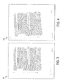
FIGURE 3 shows a scanned original page; -
FIGURE 4 shows a modifiedFIGURE 3 ; -
FIGURE 5 illustrates fingerprint locations; -
FIGURE 6 illustrates fingerprint locations; -
FIGURES 7 and 8 show results of fingerprint comparison analysis; -
FIGURE 9 sets out an environment; -
FIGURE 10 illustrates a method; -
FIGURE 11 illustrates a method; -
FIGURE 12 illustrates a method; -
FIGURE 13 is a method; -
FIGURE 14A illustrates obtaining a Triangle Ratio; -
FIGURE 14B is Quantization of the Triangle Ratio; -
FIGURE 15 is a method; -
FIGURES 16A and 16B illustrate a method; and -
FIGURE 17 is a method. -
FIGURES 1 and 2 illustrate a two-dimensional (2D) visual fingerprinting and highlighting method. Visual fingerprints of eachdocument pages - The reviewer can therefore quickly focus on the key areas of difference (highlighted by the
ovals -
FIGURE 3 illustrates scannedoriginal page 300.FIGURE 4 shows a query image of scanned modifiedpage 400.Query page image 400 contains intentionally added (e.g., time stamp and document identifier) as well as content change modifications (e.g., name change and fax header) text annotations. - This application automatically finds any page in the collection that contains some duplicated content of
query page image 400, automatically highlights the duplicated content, or the difference, between each such found page and the query page image. - 2D visual fingerprinting technology is used to address the above. Initially, pages in the document collection are processed to extract visual fingerprints and build a fingerprint index. The collection need only be indexed once, and this can be done in advance.
-
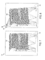
FIGURE 5 illustratesimage 500 with fingerprint locations found for the scanned original page inFIGURE 3 super-imposed over the scanned original content of that page. Fingerprint locations are shown as node circles 502 (only a sampling are numbered), and a grid mesh of line-segments 504 (only a sampling are numbered) connect the fingerprint locations. - The query page image is processed in a similar manner.
FIGURE 6 illustratesimage 600 with fingerprint locations found for the query image inFIGURE 4 . The fingerprint locations are shown as node circles 602 (only a sampling are numbered), and a grid mesh of line-segments 604 (only a sampling are numbered) connect the fingerprint locations. - Comparing the grid mesh structure of query image in
FIGURE 6 to the grid mesh structure of scanned original inFIGURE 5 , common and different parts can be identified. - Query page image fingerprints are looked up in a document collection fingerprint index to retrieve all pages in the collection that have a certain number of similar fingerprints.
- Matching pages are ranked and sorted by decreasing level of similarity based on the number of matching fingerprints. Resulting pages are presented to a user in ranked similarity order to the query image.
- Fingerprint comparison analysis is carried out on each returned page to determine fingerprint correspondence with the query image fingerprints. Analysis identifies clusters of unique (non-corresponding) fingerprints and computes a 2D visual measure (e.g., an ellipse), for each cluster that is proportional to the cluster distribution and other factors such as the number of corresponding fingerprints occurring inside or in close proximity to a cluster, cluster fingerprint density, etc.
- The resulting set of ellipses is added or super-imposed on top of the visual image display, to automatically highlight the areas of difference relative to the query page image.
-
FIGURES 7 and 8 illustrate results of fingerprint comparison analysis between the query page image inFIGURE 4 and the scanned original page inFIGURE 3 .FIGURE 7 shows the document page inFIGURE 3 augmented with two clusters of non-corresponding fingerprints surrounded byellipses ellipse 704 surrounding the cluster in the bottom right-hand corner is a document identification label entitled "USW 2159" which is understood not part of the original document. A unique label is stamped on each document as part of the scanning process. The dotted-line in this case indicates the unique identification stamp. -
FIGURE 8 showsresult 800 of the fingerprint comparison analysis for the query image inFIGURE 4 with the difference from the document page inFIGURE 3 highlighted byellipses solid ellipses FIGURE 8 highlight the changes: time-stamp and text modification annotations with respect to the original document content. Dottedellipse 806 on the bottom right ofFIGURE 8 indicates a unique identification stamp that is added as part of the scanning process. While the circles and grid lines are shown inFIGURES 7 and 8 , they may not be shown in practice, and therefore the output comparison would look more like that shown inFIGURES 1 and 2 . -
FIGURE 4 illustrates an example of scanned/faxed copy of original page shown inFIGURE 3 , where the scanned/faxed image ofFIGURE 4 is a rotated modified faxed page. - The system and method described herein may work an environment or network as illustrated in
FIGURE 9 . Thenetwork 900 is comprised of a series of connections such aswires 902, which may branch withthird wire 906 atwire junctions 904, may connect a standalone peripheral device or pass through a peripheral to connect to other devices, such ascomputers color printer 910, or other thancolor printer 912, color laser printers, 920, 922, or one other thancolor laser printer 924. The network may also incorporatescanner 930,fax machine 940, photocopier 950,color photocopier 952, a combination color printer/scanner/fax machine 954. The network may also containcomputer terminal 960, or standalone hard drivedata storage medium 964. The network may also contain wirelessnetwork transmitter receiver 970 and interface withlaptop computer 972, or a plurality oflaptop computers 974. The network may interconnect with any form ofnetwork 980 including but not limited to Internet, Intranet or other communication network. The present system and method may interface with a plurality of peripheraldata capturing devices 990 including, digitalstill camera 991,digital video camera 992,cellular telephone 993,scanner 994,personal data assistant 995, ordocument indexing system 996. The present concepts may be implemented in networks having various combinations of the above components, going from a network having a single device to one which includes thousands or more connected devices. Further, various ones of the above components may have memory storage areas arranged in any of a number of known configurations which may be useful in implementing the concepts to be described. The storage areas may be RAM, ROM, Flash Memory, web services, cloud storage facilities or other memory types which can hold software incorporating the concepts of the present application. Various ones of the components ofFIGURE 9 , such as but not limited to the computers, include processors to process instructions from software loaded on or otherwise accessible by the components. It is to be understood various ones of the components having the processors may have more than one processor whereby processing of the instructions can be divided among the multiple processors. Alternatively, a single processor can operate to divide the instructions, whereby processing can occur in a multi-threaded environment. The computers may be other computing devices than those mentioned above and will include electronic/digital processors as well as or in the alternative graphical electronic/digital processors (GPUs). -
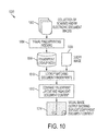
FIGURE 10 illustratesmethod 1000 of detecting duplicate document content in a large document collection and automatically highlighting duplicate/different document content using 2D visual fingerprints. Adocument collection 1002 is first indexed and organized in a particular manner (such as by use of a Fan Tree) for fast andefficient fingerprint lookup 1004. A document collection in this context is an abstract logical document collection that may be physically located at one location or physically distributed in a set of sub-collections across many folders, drives, systems, networks, remote servers, web services and/or cloud storage facilities, etc. - Visual fingerprinting and
indexing process 1004 is applied to the pages of the documents in the collection. The fingerprints of each image and their locations are added to afingerprint lookup index 1006, found in a memory. -
Fingerprint lookup index 1006 need only be fully constructed once for a given document collection. Once a collection has been indexed in this manner, the fingerprint index can be saved and re-used. The fingerprint index can be incrementally updated when documents are added or removed from the collection by adding the fingerprints of new documents to the index and removing existing fingerprints of deleted documents. The incremental update may be applied as a background process in a separate thread. - The method of detecting duplicate document content is presented with a
query page image 1008. The query page image is fingerprinted and the fingerprints are looked up 1010 in the fingerprint lookup index to return a list of collection documents and the number of matching fingerprints corresponding to query page image fingerprints. The list of returned collection documents is ordered by the number of corresponding fingerprints (e.g., most to least). Only the top matching pages above a required minimum of corresponding fingerprints may be retained. - For each matching page in the collection, the corresponding fingerprints are retrieved from memory and compared with the
query fingerprints 1012. This fingerprint comparison analysis is carried out to determine the fingerprint correspondence between the query page image and the matching document. The analysis takes into account the fingerprint locations and their corresponding layout. Sets of corresponding identical fingerprints represent regions of matching document content, while clusters of unique (non-corresponding) fingerprints in either image represent differences in document content. Depending on the application to which the process is being employed, either the duplicate or non-duplicate document content may be automatically highlighted. For applications of duplicate and near duplicate content detection, it is often desirable to highlight the difference in content instead of the duplicate content (which in any case is identical between the two images). - One method of automatically highlighting differences is by calculating the mean and standard deviation for the 2D locations of each cluster of unique (non-corresponding) fingerprints of the query and matching image collection document. An ellipse is computed for each cluster of non-corresponding fingerprints. The ellipse location is centered at the cluster mean, and the size of the ellipse is proportional to the estimated second moments of fingerprint location distribution within cluster. In addition, the ellipse size may be further controlled in proportion to the number and location of any corresponding fingerprints occurring inside or in close proximity to the cluster, and by cluster complexity, shape, and fingerprint density. The resulting ellipse is drawn or super-imposed on top of the visual image display in highlight color, or saved in a separate image layer or metadata.
-
FIGURE 11 illustratesindexing method 1100 which provides additional details to the indexing of a collection of documents to create fingerprint lookup index 1006 (seeFIGURE 10 ).Indexing method 1100 is comprised of processing a sequence of page images, computing visual fingerprints and adding the fingerprints and their locations to a specified image fingerprint lookup index. -
Process 1100 is shown in this embodiment to be used in connection with a document collection that contains scannedhardcopy documents 1102 and/or electronically generateddocuments 1104. Different document types require different pre-processing. Scanned hardcopy documents are comprised of scanned page images that may contain less than ideal conditions such as fax or scanner noise, page skew and dark image background, for example. Animage processing stage 1106 may be included to remedy and further enhance the image prior to fingerprinting.Electronic documents 1104, on the other hand, such as Microsoft Word, Excel, PowerPoint, or Adobe PDF, for example, are rendered 1108, by drawing the content to create a sequence of page images for fingerprinting. -
Indexing method 1100 processespage images 1110 from the documents in the collection. The order of indexing documents is not significant. For each document in the collection, the system automatically determines the document type, whether a scanned hardcopy or electronic original, and automatically appliesappropriate processing -
Keypoint identification 1112 is responsible for identifying stable and repeatable keypoints in each page image. Previously developed methods of finding keypoints in a document or photo page image have been developed. One embodiment i s based on word-blob centroids, described inU.S. Serial Number 12/147,624 - Another embodiment is detailed in
US Serial Number 12/147,867 - Depending on the application, weaker keypoints found below a certain measure of strength threshold may be discarded.
- 2D visual fingerprints are computed 1114 from the resulting keypoints. Previously developed methods of computing visual fingerprints from image keypoints, based on geometry or image appearance have been developed. In one embodiment, a geometry-based method of computing 2D visual fingerprints for document images is described in 20080166-US-NP: METHOD AND SYSTEM FOR FINDING A DOCUMENT IMAGE IN A DOCUMENT COLLECTION USING LOCALIZED TWO-DIMENSIONAL VISUAL FINGERPRINTS, Kletter, et al.
- The resulting fingerprints and their locations are added 1116 to the image
collection fingerprint index 1006. The image fingerprints are added to the index and hashed in a special manner in order to facilitate fast and efficient fingerprint lookup (e.g., such as by use of a Fan Tree). In one embodiment, one effective method of organizing the fingerprint in memory for fast lookup is detailed inU.S. Serial Number 12/147,624 - Another embodiment for finding a picture image in an image collection is described in
U.S. Serial Number: 12/163,186 -
Process 1100 repeats for each page of each document in the collection until thelast page image 1118 is encountered. At this point, resulting fingerprint lookup index 1006 (see alsoFigure 10 ) is saved and may be re-used.Fingerprint lookup index 1006 can be incrementally updated when additional pages are added or removed from the collection as outlined in [0037] above. -
FIGURE 12 illustrates query process/method 1200 of detecting duplicate document content using 2D visual fingerprints using a query image; automatically highlighting content difference; and ranking pages by page similarity level. -
Query process 1200 begins with a query page presented at the input. As previously mentioned the systems described herein will work with a variety of document types, including but not limited to scanneddocuments 1202 andelectronic documents 1204. The query page itself may be a page of scannedhardcopy document 1202 or a page image ofelectronic document 1204. The system automatically determines (e.g., by reading an accompanying information file) the document type, whether scanned hardcopy or electronic original, and automatically applies theappropriate processing improved query image 1210 prior to fingerprinting. Alternatively, the system may render an electronic query page of a Microsoft Word, PowerPoint or PDF document page into aquery image 1210. At this time the processing is being applied to the query page image image rather than to document collection page images. - The same method of identifying keypoints 1212 and computing 2D
visual fingerprints 1214 used during indexing is applied to the query page image. Resulting fingerprints are looked up as aquery 1216 in the collectionfingerprint lookup index 1006 to return a list of matchingpages 1218 from the collection of documents with matching corresponding fingerprints to the query page image fingerprints. The list is ordered by the number of matching corresponding fingerprints, the match rank. - Then the process will identify one of the pages from the list (Get Next Page Image) 1220 as a
matching page 1222. Corresponding fingerprints of matchingpage 1222 are retrieved frommemory index 1006. Then the fingerprints of matchingpage 1222 andfingerprint layout 1224 of the query page image are subject to afingerprint comparison analysis 1226. The fingerprint comparison analysis is carried out to determine the fingerprint correspondence between the query page image and the present matching document page. The analysis compares fingerprint locations and corresponding layout and identifies clusters of unique (non-corresponding) fingerprints in the query and matching document image. The analysis calculates the level of matching document page similarity with the query page image based on the matching fingerprint locations. - Content differences are highlighted 1228. For example, an ellipse is computed for each cluster where the size of the ellipse is proportional to the estimated second moments of fingerprint locations within cluster. The size of the ellipse may further be adjusted in proportion to the number and location of corresponding fingerprints occurring inside or in close proximity to the cluster, and by cluster complexity, shape, and fingerprint density.
- The ellipses for all returned pages are added or super-imposed on top of the visual image display in highlight color, or saved in a separate image layer or annotated metadata.
- Each returned page that meets or exceeds a specified level of page similarity with the query image, as computed by the fingerprint comparison analysis, is added to a list of corresponding documents.
- The process checks if the present page image is the last page of the list of matching
pages 1230. If not the process obtains a next page image from thelist 1220 and repeats for each of the returned pages in the collection until the last matching page image is encountered and the process is completed 1232. At this point, the list of matching corresponding documents is ranked by page similarity level in order to return pages with the most duplicate content first. - Finally, a user may page through the list of corresponding documents.
- The above discussion related to identifying keypoints, generating fingerprints, and building a Fan Tree are expanded upon in connection with
FIGURES 13-17 . - A goal of the keypoint identification (e.g., 1112 of
Figure 11 and 1212 ofFigure 12 ) is to repeatedly and reliably find as many of the keypoints even in a degraded version of an image that is subject to at least one of, but not limited to noise, scene lighting variations, and affine transformations such as skew, warp, rotation, translation, scale, change of resolution, and the like. - One process of detecting
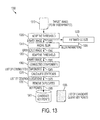
document keypoint locations 1300 of atarget image 1310 to be fingerprinted is shown inFIGURE 13 . - A
binary output image 1325 of firstAdaptive Threshold module 1320 is sent to EstimateCC Size module 1330. The term CC here stands for Connected Component, which is a maximally connected sub-group of binary pixels having the same polarity. Two pixels are in the same connected component if and only if there exists a path of the same polarity pixels between them. The purpose of the EstimateCC Size module 1330 is to dynamically estimate, fortarget image 1310 on an image by image basis, theblur parameters 1335 or blur filter size to be applied in the subsequentRadial Blur module 1340. The objective of the blurring process is to provide robust, reliable, and repeatable keypoint identification. The blurring also helps to remove noise such salt and pepper noise and eliminate small isolated features on the page. The shape of the blurring filter, for example but not limited to an approximated Gaussian shape, should be smooth enough to prevent from introducing undesirable artifacts. - The output of
Radial Blurring module 1340 isgrayscale image 1345.Adaptive Threshold module 1350 converts grayscaleRadial Blur 1340image output 1345 to binary black andwhite output 1355 byadaptive thresholding 1350. - Binary output of second
Adaptive Threshold module 1350 is abinary image 1355 and is forwarded to ConnectedComponent module 1360. Connected component methods are well known in the art, and may be considered a set of maximally connected components of a graph. - Calculate
Centroid module 1370 determines the visual center of each connected component at the output of theConnected Component module 1360. For each connected component, the horizontal centroid location is calculated by summing together the horizontal coordinates of each member pixel of the connected component and dividing the outcome by the total number of member pixels. The vertical centroid location is likewise calculated by summing together the vertical coordinates of each member pixel and dividing by the number of member pixels. The summation can be effectively done on-the-fly during the connected component analysis. Note that only the pixel members of a given connected component contribute to its centroid location, ignoring any other non-member pixel "holes". The visual centroid of each connected component is calculated with subpixel precision, since in many languages the connected components tend to be situated in text lines. - In the last processing step of the keypoint identification phase, the list of connected
component centroid locations 1375 from CalculateCentroid module 1370 is validated byRemove Duplicates module 1380, which produces a list ofkeypoints 1385. The purpose of the validation is to ensure that no two connected component shall have the same centroid locations within a given tolerance level. Duplicated connected components with nearly the same centroid locations are eliminated. - The list of remaining connected component centroids at the output of the
Remove Duplicates module 1380 becomes the final candidatequery keypoints list 1395. The overall number ofcandidate keypoints 1390 depends on the Input image content and the type of connected component processing. There can be several hundred keypoints for a typical machine printed page. - Described is the process of computing fingerprints from local groups of keypoints and packing the fingerprints for efficient storage in a Fingerprint Lookup Index or Database (e.g., 1006 of
FIGURES 10 ,11 ,12 ). Fingerprints are packed to reduce the Fingerprint Lookup Index or Database size and storage requirements. - Fingerprints are constructed as sequences of quantized, transformation-invariant 2D ratios, called persistent ratios, which are derived from the relative 2D positions of a given keypoint and its (N-1) nearest-neighbor keypoints. Thus each fingerprint is localized to a small image neighborhood around the keypoint of interest. A fingerprint sequence is dependent only on the relative 2D geometry between the keypoint of interest and its (N-1) closest keypoint neighbors. The number of neighbors N is a design parameter that influences the fingerprint strength.
- The present application makes the fingerprints robust to certain image distortions such as, but not limited to skew, warp, rotation, translation, scale, change of resolution, and the like, that commonly occur during the process of scanning or taking a picture of the image with a digital or a cell phone camera.
- As illustrated in
FIGURE 14 , it is well known that for any givenpolygon 1400 comprised of four non co-linear points {A, B, C, D} (i.e., 1410, 1420, 1430, 1440), on the object surface, comprising atriangle ABC 1450 and asecond triangle ACD 1460, the ratio of triangle areas (ABC/ACD) 1470 remains constant under any affine transformation. Hence only P=4 points are needed to calculate one triangle area ratio, illustrated as theTriangle Ratio 1470. This affine transformation has been shown to provide an acceptable model for describing the camera to planar object geometry in many practical situations. - In another embodiment, the transformation can be extended to handle perspective transformation using P=5 points (instead of 4) to calculate a single persistent ratio which is the product of two triangle ratios.
- A single fingerprint is therefore comprised of a sequence of quantized persistent transformation ratios for a group of N nearest neighbor keypoints sorted in clockwise order. To keep the fingerprint size small, the transformation ratio is quantized to Q-
levels 1480. In one embodiment, the value of Q can be conveniently chosen to be a binary power of two. InFIGURE 14B , the quantization process is illustrated as the Quantization ofTriangle Ratio 1480 ofFigure 14A for the case of Q=8. The valid range (0,∞) of a Triangle Ratio before quantization is divided into Q=8 intervals labeled '0' to '7' as shown inFIGURE 14B (1490). The interval boundaries are determined empirically to provide approximately uniform distribution of quantization labels over a large set of representative documents. The incomingtriangle ratio value 1480 is sequentially compared with increasing interval boundaries to determine the first higher or equal interval boundary, upon which the process is terminated and the corresponding label interval is assigned as the quantized result. For example, an incoming triangle ratio of 0.8253694, being less than 1.0 and higher than the previous interval boundary, is assigned a quantized value of '3'. - A potential issue in using the nearest neighbor method is that nearness is not necessarily preserved under perspective transformation. There can be no guarantee that the N nearest neighbors of a given keypoint will remain exactly the same N keypoints under arbitrary affine or perspective transformation. Still, the closest keypoints are more likely to remain in the list of N nearest neighbors than keypoints that are farther away.
- To overcome the above issue, the present application proposes to allow one or more of the neighbor keypoints to be missing in order to further increase the robustness of a fingerprint to affine or perspective transformation. Under one embodiment, one keypoint is allowed to be excluded under the consideration of limited affine distortions in small localized neighborhoods. Thus each given keypoint gives rise to a number of fingerprints N, by leaving out one keypoint at a time. Each fingerprint is created by systematically walking a remaining number of keypoints, N-1, in radial order of orientation, and recording the sequence of quantized persistent ratios for all the possible combinations of P points (P=4 for affine, P=5 for perspective transformation).
- A
Fingerprinting process 1500 is shown inFIGURE 15 . The input toFingerprinting process 1500 is the list of candidate keypoints 1510 for theinput image 1505. The first Fingerprinting processing step inFIGURE 15 is theKeypoint Triangulation module 1520. In this embodiment Delaunay orKeypoint Triangulation 1520 are used to identify the nearest keypoints to each given keypoint in a local neighborhood. By following the triangulation links, the nearest (N-1) neighbors to any given keypoint can be effectively determined. - Each candidate keypoint and its (N-1) nearest neighbors is considered as a fingerprint candidate. Each current candidate keypoint Kp is selected sequentially from
input list 1510 by the GetNext Keypoint module 1530. For each keypoint Kp, the FindNearest Neighbors module 1540 identifies the (N-1) nearest keypoints with the closest distance to the given keypoint Kp, where N is a given parameter. The Find Nearest Neighbors module uses the Delaunay orKeypoint Triangulation result 1520 to return a list of the closest keypoints to Kp, sorted by increasing distance from Kp. The first element of the returned list is always the current keypoint Kp (with a distance of zero). The value of the parameter N is adjusted to provide a reasonable tradeoff between the fingerprint "strength" or distinctiveness, the overall system performance, quantified as the number of computations per fingerprint, and the resulting database size or fingerprint size. In this example the values, N=8, 12, or 16 are used. - Points of the Find
Nearest Neighbor module 1540 need to be taken in a consistent order so that sequence of area ratios will be consistent for the same keypoint/neighborhood between database and query images. Sort inClockwise Order module 1550 sorts the list of N nearest neighbor keypoints of a given keypoint in increasing clockwise orientation. - Sort in
Clockwise Order module 1550 includes a method and system to stabilize keypoint ordering with respect to the common case of nearly co-linear keypoints. The Sort inClockwise Order module 1550 uses the first M nearest neighbors, where M<N, on the list (the closest to the given keypoint) to calculate a subgroup center of origin. The farthest (N-M) keypoints are not used in calculation of the subgroup center of origin, in order to ensure that origin will remain stable under affine or perspective transformation. Sort inClockwise Order module 1550 uses the average location of M=5, when total N=8, nearest neighbor keypoints as the center of origin for the purpose of determining keypoint ordering. - After determining the origin center of the current neighbor keypoint cluster, the Sort in
Clockwise Order module 1550 proceeds to sort the keypoints in increasing clockwise orientation order. The sorting is done on both the orientation and distance. The order is by increasing clockwise orientation order. If two or more points have roughly the same orientation, where the difference is within a predefined tolerance level, the points are sub-ordered by increasing distance for all the points of a substantially similar orientation. - For each unique subset of N keypoints, Next
Subgroup Combination module 1560 systematically and methodically selects the next subgroup combination of P=4 or P=5 keypoints depending on affine or perspective transformation case. For example, for N=8 there are 70 unique combinations of P=4 keypoint subgroups. - For each Next Subgroup Combination of P=4 keypoints, Packed
Quantized Ratio module 1570 calculates a single persistent ratio and quantizes it using a set of predefined interval boundary thresholds. The number of quantization levels Q is a design parameter. In these examples, Q=8 or Q=16 are used. The quantization threshold values are determined empirically by studying the distribution of persistent ratios in a large collection of documents of a particular type. - To further reduce the size of the
Fingerprint Database 1585, the PackedQuantized Ratio module 1570 packs a number of the resulting quantized persistent ratios into one machine word. For example, with N=8, P=4, and Q=8, the entire fingerprint sequence of 70 subgroup combinations can be tightly packed into less than four 64-bit words. In one embodiment of the present application, the size of a packed fingerprint occupies a total of three 64-bit words and three 8-bit bytes with no need to split partial information across multiple words or bytes. - The process of calculating and packing the fingerprints continues sequentially, one persistent ratio at a time, until the last combination is detected by the
Last Combination module 1580. If the current P subgroup combination is not yet thelast combination 1581, theLast Combination module 1580 routes the flow back to the NextSubgroup Combination module 1560, to obtain the next P subgroup and proceed to calculate its quantized persistent ratio and pack it. This process continues until the last P subgroup combination has been processed 1582. At this time, the resulting packedfingerprint data 1583 is written to theFingerprint Database 1585. Fingerprint data can be written to theFingerprint Database 1585 sequentially, one fingerprint at a time, as each packed fingerprint data is becoming available. - Finally, the process of writing the fingerprints continues sequentially for all the remaining keypoints, until the last keypoint is detected by
Last Keypoint module 1590. If the current keypoint combination is not yet thelast keypoint 1591,Last Keypoint module 1590 routes the flow back to GetNext Keypoint module 1530, to obtain the next keypoint and proceed to repeat the process to calculate its packed fingerprint and adding it toFingerprint Database 1585. The Fingerprinting process continues in this manner until the last keypoint combination last corresponding fingerprint has been processed 1592 and added toFingerprint Database 1585. Once the last keypoint has been addressed, the process ends 1595. - A method of calculating the fingerprint center of origin is illustrated in
FIGURES 16A-16B. FIGURE 16A illustrates the process with respect to a givenexample image 1600. The processed image is shown with the keypoints or word centroids identified by circles such as circles 1601-1602. Other circles in the figures are also word centroids. For example, numbers (1-7) also represent word centroids which are near neighbor keypoints to point X.FIGURE 16B eliminates the background processed image for better clarity, but is otherwise the same as inFIGURE 16A . In this example, a fingerprint is computed for the keypoint X, using seven additional keypoints (1-7) in the local neighborhood. In the first step, the center of origin for this fingerprint is calculated using the closest M=5 keypoints to keypoint X, that is, the average location of the points {X, 1, 2, 3 and 5}. This is likely to move the center of origin away from the point X, and away from the co-linear line of keypoint along the text line Y which includes the keypoint X, to a new center of origin followingarrow line 1620 topoint 0. The three most distant keypoints (4, 6, 7) of the seven (1-7) are not used for the center of origin calculation to stabilize thepoint 0 location by allowing for up to three (3) points to be shifted by arbitrary affine or perspective transformation. In the second step, the entire set of eight keypoints (X and 1-7) are sorted inclockwise order 1610 with respect to the newly calculated subgroup center of origin (0), resulting in the final output sequence ordering of (1, X, 2, 3, 4, 5, 6, 7) in this case. The above-described ordering depends on the point of reference. If "0" is used as the point of reference, the resulting sequence would have been 234X5671 since 1 is above the dotted line from "0". The alternative as used here is to continue to use X as reference, but pretend the keypoint mass is moved to "0", which yields the listed sequence. In the foregoing, the latter has been used, since it keeps the original keypoint location as reference, while the point "0" may move around X and cause the flipping of keypoint sequence order. However, it can be done either way, as what needs to be accomplished, in either case, is to be able to repeat the same sequence in both target and query image. The objective of the second step is to sort in clockwise order, not by distance. - Once the ordering of N nearest neighbor keypoints has been established for a given keypoint, a fingerprint can be generated. Fingerprints are formed from successive subsets of size P=4 of the keypoints in a neighborhood by excluding one or more keypoints at a time and constructing a sequence of the remaining subgroup combinations of non-excluded keypoints. Thus a group of fingerprints can be effectively constructed from the packed sequence of subgroup combinations. P-subsets of the N keypoints are considered in a systematic and consistent manner. For each, an integer is determined by computing the persistent area ratio for that P-subset, and mapping the area ratio to an integer as described herein. The length of a fingerprint for the given keypoint is the total number of such P-subsets. This is determined by the number of combinations for choosing unique P keypoints out of N keypoints. For example, if N=8 and P=4, the number of possible subgroup combinations is 70 persistent ratios. Of these, 8 fingerprints of length 35 subgroup combinations each can be constructed, for example, by excluding one keypoint at a time.
- In
FIGURE 15 , since the fingerprints in theFingerprint Database 1585 are stored in a packed format to reduce the memory size and loading time, they must first be unpacked and re-organized in a unique manner in accordance with a Fan Tree data structure to facilitate efficient fingerprint matching. It is only necessary to prepare the Fingerprint Database once, upon the first image query. The Fan Tree data structure (containing the unpacked fingerprint sequences) can be kept in memory and subsequently reused with any number of image queries. - The method of preparation of the packed
fingerprint database 1710 has previously been illustrated (FIGURE 15 ). The fingerprint information is retrieved the from thefingerprint database 1710. Each fingerprint database entry gives rise to multiple candidate fingerprints. - Exclude
Keypoint module 1720 selects multiple candidate fingerprint keypoint combinations by excluding one or more of thefingerprint keypoints 1730. This allows for one or more missing keypoints among the local neighborhood keypoints. In the present implementation, Exclude Keypoint module leaves out one keypoint. With a local neighborhood of N keypoints, this gives rise to N fingerprints for each database entry, or N fingerprints per keypoint since a database entry is made for each keypoint. -
Fingerprint Sequence module 1750 generates the sequence of N candidate fingerprints for each keypoint. For example, when N=8, ExcludeKeypoint module 1720 will cause the first fingerprint to be generated by leaving out the first keypoint and selecting the seven remaining keypoints. After that, Exclude Keypoint module will leave out the second keypoint and select the first and six last keypoints for creating the second fingerprint. This process continues until all excluded keypoint combinations have been encountered. In this example each database entry will generate 8 candidate fingerprints, each oflength 7 choose 4 = 35. - With N=8 and P=4, there are (8 choose 4) =70 unique combinations of 4 keypoint subgroups. This is what gets stored in
database 1710 in a packed format for each keypoint. - Next fingerprints for the case of a single missing keypoint are generated. However, which keypoint may be missing is not known in advance, so preparation for all possibilities is undertaken. With N=8, there are 8 possible ways of a single missing keypoint: either the first, or the second, or third, etc.for a total of 8 cases. A different fingerprint for each one of these cases is computed. Each fingerprint in this case is only based on 7 keypoints (because one of the original 8 is missing). The length of each fingerprint in this case is (7 choose 4)=35, and there are 8 of them total. This means that each fingerprint is comprised of a sequence of 35 integers (quantized ratios) in the range 0-7. The 8 fingerprints are added to the Fan Tree data.
- At query time, 8 keypoints (current and 7 closest) are generated, and again 8 query fingerprints are computed using the same method, and likewise excluding one keypoint at a time. An attempt is made to match the keypoints against the Fan Tree content. Matching is stopped upon the first obtained match. If a single keypoint is missing from the query image (it does not matter which), one of the query fingerprints out of the 8 is bound to have a match (to the one with the 7 other keypoints present). If no keypoint is missing (all 8 present), then there would be 8 matches (because any group of 7 will match), except the process stops after the first positive match since there is no need to continue checking. If, however, two keypoints or more are missing at the same time, there would be no match for this location. If so desired, the system could easily handle more missing keypoints by extending the method to allow more missing keypoints (e.g., 2 out of 8, etc.).
-
Fingerprint Data 1760 output fromFingerprint Sequence module 1750, together withunique image ID 1740 that is retrieved from the database for the current image,form fingerprint record 1780.Fingerprint record 1780 is stored in a corresponding Fan Tree Leaf node location which is addressed byFan Tree module 1770. Fan Tree Leaf node information is stored as a linked list offingerprint records 1780 in the correspondingFingerprint Data structure 1790. Only the actual Fan Tree Leaf nodes corresponding to real fingerprints are populated. The first fingerprint to arrive at a particular leaf node populates that leaf node for the first time. If more than one fingerprint happens to arrive at the same leaf node again (i.e., following the same Fan Tree path), the new fingerprint information is added at the same leaf node by linking the new fingerprint information with the last previous fingerprint information on that leaf node.
Claims (10)
- A method of detecting duplicate document content, the method comprising:inputting a query document page to a document detection system;comparing the query document page with pages of documents stored in a document collection by using visual fingerprints of a two-dimensional visual fingerprint detection process; andautomatically highlighting duplicate or different document content of the query document page and at least one document page of the stored documentation collection based on the results of using the two-dimensional visual fingerprint detection.
- The method according to claim 1, wherein a list of the documents of the document collection having matching fingerprints to the query document page is returned and the returning of the list of documents having matching fingerprints to the query document page includes forming the list from only documents of the document collection having a predefined required minimum corresponding number of matching fingerprints.
- The method according to claim 1 or claim 2, wherein the automatically highlighting is accomplished by calculating a mean and standard deviation for two-dimensional locations of each cluster of the non-corresponding fingerprints of the query document page and one of the document pages of the document collection.
- The method according to any of the preceding claims, wherein the automatically highlighting includes generating a geometric element for each cluster of non-corresponding fingerprints on at least one of the query document page and one of the document pages of the returned documents of the document collection.
- The method according to claim 4, wherein the geometric element is centered at the cluster mean and the size of the geometric element is proportional to the estimated second moments of fingerprint location distribution within the cluster.
- The method according to claim 5, wherein the size of the geometric element is further controlled in proportion to the number and location of any corresponding fingerprints occurring inside or in close proximity to the cluster, and by cluster complexity, shape, and fingerprint density.
- The method according to any of claims 4 to 6, wherein the geometric element is drawn or super-imposed on top of the visual image display in a highlight color, or is saved in a separate image layer of metadata.
- The method according to any of the preceding claims, wherein the document collection is an abstract logical document collection that may be physically distributed in a set of sub-collections across any one of a number of folders, drives systems, networks, remote servers, web-servers, and/or cloud storage facilities.
- A method of detecting duplicate document content in a large document collection and automatically highlighting duplicate or different document content among the detected document content using two-dimensional visual fingerprints, the method comprising:generating a document collection;visually fingerprinting documents of the document collection;indexing the fingerprinted documents of the document collection;storing in memory the indexed fingerprints of the documents of the document collection;presenting a query document to a content detection system;fingerprinting the query document;looking up the fingerprints of the query document in the memory storing the indexed fingerprints of the documents of the document collection;returning a list of documents of the document collection having fingerprints matching the fingerprints of the query document;performing a fingerprint comparison for each document of the document collection having matching fingerprints to the query document, wherein the comparison includes comparing the fingerprint locations and their corresponding layout in the documents being compared; andautomatically highlighting one of the duplicate or non-duplicate document content between the query document and the one of the documents of the document collection.
- The method according to claim 9, wherein the document collection is an abstract logical document collection that may be physically distributed in a set of sub-collections across any one of a number of folders, drives systems, networks, remote servers, web-servers, and/or cloud storage facilities.
Applications Claiming Priority (1)
| Application Number | Priority Date | Filing Date | Title |
|---|---|---|---|
| US12/907,226 US8750624B2 (en) | 2010-10-19 | 2010-10-19 | Detection of duplicate document content using two-dimensional visual fingerprinting |
Publications (3)
| Publication Number | Publication Date |
|---|---|
| EP2444920A2 true EP2444920A2 (en) | 2012-04-25 |
| EP2444920A3 EP2444920A3 (en) | 2013-04-03 |
| EP2444920B1 EP2444920B1 (en) | 2019-08-21 |
Family
ID=44785568
Family Applications (1)
| Application Number | Title | Priority Date | Filing Date |
|---|---|---|---|
| EP11184495.7A Active EP2444920B1 (en) | 2010-10-19 | 2011-10-10 | Detection of duplicate document content using two-dimensional visual fingerprinting |
Country Status (3)
| Country | Link |
|---|---|
| US (1) | US8750624B2 (en) |
| EP (1) | EP2444920B1 (en) |
| JP (1) | JP5753473B2 (en) |
Cited By (1)
| Publication number | Priority date | Publication date | Assignee | Title |
|---|---|---|---|---|
| CN105787415A (en) * | 2014-12-18 | 2016-07-20 | 富士通株式会社 | Document image processing apparatus, method and scanner |
Families Citing this family (28)
| Publication number | Priority date | Publication date | Assignee | Title |
|---|---|---|---|---|
| US8943144B2 (en) * | 2009-12-10 | 2015-01-27 | International Business Machines Corporation | Consolidating duplicate messages for a single destination on a computer network |
| US8554021B2 (en) | 2010-10-19 | 2013-10-08 | Palo Alto Research Center Incorporated | Finding similar content in a mixed collection of presentation and rich document content using two-dimensional visual fingerprints |
| US8527516B1 (en) * | 2011-02-25 | 2013-09-03 | Google Inc. | Identifying similar digital text volumes |
| US10685234B2 (en) | 2012-03-31 | 2020-06-16 | Xerox Corporation | Automatic and semi-automatic metadata generation via inheritance in homogeneous and heterogeneous environments |
| US8838657B1 (en) | 2012-09-07 | 2014-09-16 | Amazon Technologies, Inc. | Document fingerprints using block encoding of text |
| US9773039B2 (en) * | 2012-09-14 | 2017-09-26 | Fti Consulting, Inc. | Computer-implemented system and method for identifying near duplicate documents |
| TWI512642B (en) * | 2013-01-25 | 2015-12-11 | Delta Electronics Inc | Method of fast image matching |
| US8958651B2 (en) * | 2013-05-30 | 2015-02-17 | Seiko Epson Corporation | Tree-model-based stereo matching |
| US10303682B2 (en) * | 2013-09-21 | 2019-05-28 | Oracle International Corporation | Automatic verification and triage of query results |
| JP6232940B2 (en) * | 2013-11-01 | 2017-11-22 | 富士ゼロックス株式会社 | Image information processing apparatus and program |
| CN103714345B (en) * | 2013-12-27 | 2018-04-06 | Tcl集团股份有限公司 | A kind of method and system of binocular stereo vision detection finger fingertip locus |
| US9886422B2 (en) * | 2014-08-06 | 2018-02-06 | International Business Machines Corporation | Dynamic highlighting of repetitions in electronic documents |
| US9805099B2 (en) * | 2014-10-30 | 2017-10-31 | The Johns Hopkins University | Apparatus and method for efficient identification of code similarity |
| US9836435B2 (en) | 2015-03-19 | 2017-12-05 | International Business Machines Corporation | Embedded content suitability scoring |
| RU2613848C2 (en) * | 2015-09-16 | 2017-03-21 | Общество с ограниченной ответственностью "Аби Девелопмент" | Detecting "fuzzy" image duplicates using triples of adjacent related features |
| US11068546B2 (en) | 2016-06-02 | 2021-07-20 | Nuix North America Inc. | Computer-implemented system and method for analyzing clusters of coded documents |
| US10229315B2 (en) * | 2016-07-27 | 2019-03-12 | Intuit, Inc. | Identification of duplicate copies of a form in a document |
| US20180101540A1 (en) * | 2016-10-10 | 2018-04-12 | Facebook, Inc. | Diversifying Media Search Results on Online Social Networks |
| US10083353B2 (en) | 2016-10-28 | 2018-09-25 | Intuit Inc. | Identifying document forms using digital fingerprints |
| US10372813B2 (en) | 2017-01-17 | 2019-08-06 | International Business Machines Corporation | Selective content dissemination |
| US10318563B2 (en) | 2017-08-23 | 2019-06-11 | Lead Technologies, Inc. | Apparatus, method, and computer-readable medium for recognition of a digital document |
| CN109697231A (en) * | 2017-10-24 | 2019-04-30 | 北京国双科技有限公司 | A kind of display methods, system, storage medium and the processor of case document |
| CN108664900B (en) * | 2018-04-20 | 2022-05-27 | 上海掌门科技有限公司 | Method and equipment for identifying similarities and differences of written works |
| US20200019583A1 (en) * | 2018-07-11 | 2020-01-16 | University Of Southern California | Systems and methods for automated repair of webpages |
| CN109471921A (en) * | 2018-11-23 | 2019-03-15 | 深圳市元征科技股份有限公司 | A kind of text duplicate checking method, device and equipment |
| DE112020006703T5 (en) * | 2020-02-10 | 2022-12-15 | Mitsubishi Electric Corporation | Display image data editing program, display image data editing apparatus and display image data editing method |
| JP7400543B2 (en) * | 2020-02-28 | 2023-12-19 | 富士フイルムビジネスイノベーション株式会社 | Information processing device and program |
| CN113297888A (en) * | 2020-09-18 | 2021-08-24 | 阿里巴巴集团控股有限公司 | Method and device for checking image content detection result |
Family Cites Families (35)
| Publication number | Priority date | Publication date | Assignee | Title |
|---|---|---|---|---|
| JPH0589190A (en) * | 1991-09-27 | 1993-04-09 | Meidensha Corp | Drawing information checking system |
| CA2077274C (en) | 1991-11-19 | 1997-07-15 | M. Margaret Withgott | Method and apparatus for summarizing a document without document image decoding |
| US5465303A (en) | 1993-11-12 | 1995-11-07 | Aeroflex Systems Corporation | Automated fingerprint classification/identification system and method |
| US5465353A (en) | 1994-04-01 | 1995-11-07 | Ricoh Company, Ltd. | Image matching and retrieval by multi-access redundant hashing |
| US5613014A (en) | 1994-10-12 | 1997-03-18 | Martin Marietta Corp. | Fingerprint matching system |
| US5987171A (en) * | 1994-11-10 | 1999-11-16 | Canon Kabushiki Kaisha | Page analysis system |
| JP3647075B2 (en) * | 1995-01-26 | 2005-05-11 | キヤノン株式会社 | Image search method and apparatus |
| US5850476A (en) | 1995-12-14 | 1998-12-15 | Xerox Corporation | Automatic method of identifying drop words in a document image without performing character recognition |
| US5893908A (en) | 1996-11-21 | 1999-04-13 | Ricoh Company Limited | Document management system |
| US6041133A (en) | 1996-12-13 | 2000-03-21 | International Business Machines Corporation | Method and apparatus for fingerprint matching using transformation parameter clustering based on local feature correspondences |
| US7844594B1 (en) | 1999-06-18 | 2010-11-30 | Surfwax, Inc. | Information search, retrieval and distillation into knowledge objects |
| US20060259524A1 (en) | 2003-03-17 | 2006-11-16 | Horton D T | Systems and methods for document project management, conversion, and filing |
| US7359532B2 (en) | 2003-12-11 | 2008-04-15 | Intel Corporation | Fingerprint minutiae matching using scoring techniques |
| US7702673B2 (en) | 2004-10-01 | 2010-04-20 | Ricoh Co., Ltd. | System and methods for creation and use of a mixed media environment |
| JP4517822B2 (en) * | 2004-11-05 | 2010-08-04 | 富士ゼロックス株式会社 | Image processing apparatus and program |
| US20060104484A1 (en) | 2004-11-16 | 2006-05-18 | Bolle Rudolf M | Fingerprint biometric machine representations based on triangles |
| US20060120686A1 (en) * | 2004-12-03 | 2006-06-08 | Frank Liebenow | Method, apparatus and system for storage and retrieval of images |
| JP4533187B2 (en) * | 2005-03-01 | 2010-09-01 | キヤノン株式会社 | Image processing apparatus and control method thereof |
| US7519200B2 (en) | 2005-05-09 | 2009-04-14 | Like.Com | System and method for enabling the use of captured images through recognition |
| US7403932B2 (en) | 2005-07-01 | 2008-07-22 | The Boeing Company | Text differentiation methods, systems, and computer program products for content analysis |
| US7801392B2 (en) | 2005-07-21 | 2010-09-21 | Fuji Xerox Co., Ltd. | Image search system, image search method, and storage medium |
| WO2007080133A2 (en) | 2006-01-16 | 2007-07-19 | Thomson Licensing | Method for determining and fingerprinting a key frame of a video sequence |
| ATE470912T1 (en) | 2006-04-28 | 2010-06-15 | Toyota Motor Europ Nv | ROBUST DETECTOR AND DESCRIPTOR FOR A POINT OF INTEREST |
| US8244036B2 (en) | 2007-01-24 | 2012-08-14 | Bluebeam Software, Inc. | Method for emphasizing differences in graphical appearance between an original document and a modified document with annotations |
| US8055079B2 (en) | 2007-03-06 | 2011-11-08 | Sharp Kabushiki Kaisha | Image processing method, image processing apparatus, and image forming apparatus |
| US8972299B2 (en) | 2008-01-07 | 2015-03-03 | Bally Gaming, Inc. | Methods for biometrically identifying a player |
| US8233722B2 (en) * | 2008-06-27 | 2012-07-31 | Palo Alto Research Center Incorporated | Method and system for finding a document image in a document collection using localized two-dimensional visual fingerprints |
| US8144947B2 (en) | 2008-06-27 | 2012-03-27 | Palo Alto Research Center Incorporated | System and method for finding a picture image in an image collection using localized two-dimensional visual fingerprints |
| US8233716B2 (en) | 2008-06-27 | 2012-07-31 | Palo Alto Research Center Incorporated | System and method for finding stable keypoints in a picture image using localized scale space properties |
| US8520941B2 (en) * | 2008-12-09 | 2013-08-27 | Xerox Corporation | Method and system for document image classification |
| US8548193B2 (en) | 2009-09-03 | 2013-10-01 | Palo Alto Research Center Incorporated | Method and apparatus for navigating an electronic magnifier over a target document |
| US8380588B2 (en) | 2010-01-14 | 2013-02-19 | Oracle International Corporation | Side-by-side comparison of associations for multi-level bills of material |
| US9514103B2 (en) | 2010-02-05 | 2016-12-06 | Palo Alto Research Center Incorporated | Effective system and method for visual document comparison using localized two-dimensional visual fingerprints |
| US8086039B2 (en) | 2010-02-05 | 2011-12-27 | Palo Alto Research Center Incorporated | Fine-grained visual document fingerprinting for accurate document comparison and retrieval |
| US8554021B2 (en) | 2010-10-19 | 2013-10-08 | Palo Alto Research Center Incorporated | Finding similar content in a mixed collection of presentation and rich document content using two-dimensional visual fingerprints |
-
2010
- 2010-10-19 US US12/907,226 patent/US8750624B2/en active Active
-
2011
- 2011-10-10 EP EP11184495.7A patent/EP2444920B1/en active Active
- 2011-10-14 JP JP2011227416A patent/JP5753473B2/en active Active
Cited By (1)
| Publication number | Priority date | Publication date | Assignee | Title |
|---|---|---|---|---|
| CN105787415A (en) * | 2014-12-18 | 2016-07-20 | 富士通株式会社 | Document image processing apparatus, method and scanner |
Also Published As
| Publication number | Publication date |
|---|---|
| JP5753473B2 (en) | 2015-07-22 |
| US20120093421A1 (en) | 2012-04-19 |
| EP2444920B1 (en) | 2019-08-21 |
| JP2012089132A (en) | 2012-05-10 |
| US8750624B2 (en) | 2014-06-10 |
| EP2444920A3 (en) | 2013-04-03 |
Similar Documents
| Publication | Publication Date | Title |
|---|---|---|
| EP2444920B1 (en) | Detection of duplicate document content using two-dimensional visual fingerprinting | |
| EP2138953B1 (en) | Method and system for finding a document image in a document collection using localized two-dimensional visual fingerprints | |
| JP5180156B2 (en) | System and method for finding picture images in an image collection using localized two-dimensional visual fingerprints | |
| EP2444921B1 (en) | Finding Similar Content in a Mixed Collection of Presentation and Rich Document Content using Two-dimensional Visual Fingerprints | |
| Margeta et al. | Fine-tuned convolutional neural nets for cardiac MRI acquisition plane recognition | |
| US8712156B2 (en) | Comparison of visual information | |
| EP2364011B1 (en) | Fine-grained visual document fingerprinting for accurate document comparison and retrieval | |
| US10210427B2 (en) | Systems, methods, and devices for image matching and object recognition in images | |
| JP5527555B2 (en) | Image database creation method, creation program, and image search method | |
| KR101548928B1 (en) | Invariant visual scene and object recognition | |
| EP2321787A2 (en) | Annotating images | |
| US10846562B2 (en) | Systems and methods for image matching | |
| KR101755980B1 (en) | Copy-Move Forgery Detection method and apparatus based on scale space representation | |
| US8938118B1 (en) | Method of neighbor embedding for OCR enhancement | |
| Nikolopoulos et al. | Image replica detection system utilizing R-trees and linear discriminant analysis | |
| Hare et al. | MapSnapper: engineering an efficient algorithm for matching images of maps from mobile phones | |
| Hong et al. | Information Extraction and Analysis on Certificates and Medical Receipts | |
| Jun et al. | Iriw: Image retrieval based image watermarking for large-scale image databases | |
| CN110633733A (en) | Intelligent image matching method and device and computer readable storage medium | |
| Havasi et al. | Search in WikiImages using mobile phone | |
| Jeong et al. | Efficient image feature combination with hierarchical scheme for content-based image management system | |
| CN112287136A (en) | Image feature index library establishing method and similar image determining method | |
| Souraya et al. | Image Retrieval Using Patch-Based Features |
Legal Events
| Date | Code | Title | Description |
|---|---|---|---|
| AK | Designated contracting states |
Kind code of ref document: A2 Designated state(s): AL AT BE BG CH CY CZ DE DK EE ES FI FR GB GR HR HU IE IS IT LI LT LU LV MC MK MT NL NO PL PT RO RS SE SI SK SM TR |
|
| AX | Request for extension of the european patent |
Extension state: BA ME |
|
| PUAI | Public reference made under article 153(3) epc to a published international application that has entered the european phase |
Free format text: ORIGINAL CODE: 0009012 |
|
| PUAL | Search report despatched |
Free format text: ORIGINAL CODE: 0009013 |
|
| AK | Designated contracting states |
Kind code of ref document: A3 Designated state(s): AL AT BE BG CH CY CZ DE DK EE ES FI FR GB GR HR HU IE IS IT LI LT LU LV MC MK MT NL NO PL PT RO RS SE SI SK SM TR |
|
| AX | Request for extension of the european patent |
Extension state: BA ME |
|
| RIC1 | Information provided on ipc code assigned before grant |
Ipc: G06K 9/00 20060101ALI20130225BHEP Ipc: G06K 9/20 20060101AFI20130225BHEP |
|
| 17P | Request for examination filed |
Effective date: 20131004 |
|
| RBV | Designated contracting states (corrected) |
Designated state(s): AL AT BE BG CH CY CZ DE DK EE ES FI FR GB GR HR HU IE IS IT LI LT LU LV MC MK MT NL NO PL PT RO RS SE SI SK SM TR |
|
| STAA | Information on the status of an ep patent application or granted ep patent |
Free format text: STATUS: EXAMINATION IS IN PROGRESS |
|
| 17Q | First examination report despatched |
Effective date: 20170809 |
|
| GRAP | Despatch of communication of intention to grant a patent |
Free format text: ORIGINAL CODE: EPIDOSNIGR1 |
|
| STAA | Information on the status of an ep patent application or granted ep patent |
Free format text: STATUS: GRANT OF PATENT IS INTENDED |
|
| INTG | Intention to grant announced |
Effective date: 20190318 |
|
| GRAS | Grant fee paid |
Free format text: ORIGINAL CODE: EPIDOSNIGR3 |
|
| GRAA | (expected) grant |
Free format text: ORIGINAL CODE: 0009210 |
|
| STAA | Information on the status of an ep patent application or granted ep patent |
Free format text: STATUS: THE PATENT HAS BEEN GRANTED |
|
| AK | Designated contracting states |
Kind code of ref document: B1 Designated state(s): AL AT BE BG CH CY CZ DE DK EE ES FI FR GB GR HR HU IE IS IT LI LT LU LV MC MK MT NL NO PL PT RO RS SE SI SK SM TR |
|
| REG | Reference to a national code |
Ref country code: GB Ref legal event code: FG4D |
|
| REG | Reference to a national code |
Ref country code: CH Ref legal event code: EP |
|
| REG | Reference to a national code |
Ref country code: DE Ref legal event code: R096 Ref document number: 602011061394 Country of ref document: DE |
|
| REG | Reference to a national code |
Ref country code: AT Ref legal event code: REF Ref document number: 1170593 Country of ref document: AT Kind code of ref document: T Effective date: 20190915 |
|
| REG | Reference to a national code |
Ref country code: IE Ref legal event code: FG4D |
|
| REG | Reference to a national code |
Ref country code: LT Ref legal event code: MG4D |
|
| REG | Reference to a national code |
Ref country code: NL Ref legal event code: MP Effective date: 20190821 |
|
| PG25 | Lapsed in a contracting state [announced via postgrant information from national office to epo] |
Ref country code: LT Free format text: LAPSE BECAUSE OF FAILURE TO SUBMIT A TRANSLATION OF THE DESCRIPTION OR TO PAY THE FEE WITHIN THE PRESCRIBED TIME-LIMIT Effective date: 20190821 Ref country code: HR Free format text: LAPSE BECAUSE OF FAILURE TO SUBMIT A TRANSLATION OF THE DESCRIPTION OR TO PAY THE FEE WITHIN THE PRESCRIBED TIME-LIMIT Effective date: 20190821 Ref country code: NO Free format text: LAPSE BECAUSE OF FAILURE TO SUBMIT A TRANSLATION OF THE DESCRIPTION OR TO PAY THE FEE WITHIN THE PRESCRIBED TIME-LIMIT Effective date: 20191121 Ref country code: FI Free format text: LAPSE BECAUSE OF FAILURE TO SUBMIT A TRANSLATION OF THE DESCRIPTION OR TO PAY THE FEE WITHIN THE PRESCRIBED TIME-LIMIT Effective date: 20190821 Ref country code: SE Free format text: LAPSE BECAUSE OF FAILURE TO SUBMIT A TRANSLATION OF THE DESCRIPTION OR TO PAY THE FEE WITHIN THE PRESCRIBED TIME-LIMIT Effective date: 20190821 Ref country code: PT Free format text: LAPSE BECAUSE OF FAILURE TO SUBMIT A TRANSLATION OF THE DESCRIPTION OR TO PAY THE FEE WITHIN THE PRESCRIBED TIME-LIMIT Effective date: 20191223 Ref country code: BG Free format text: LAPSE BECAUSE OF FAILURE TO SUBMIT A TRANSLATION OF THE DESCRIPTION OR TO PAY THE FEE WITHIN THE PRESCRIBED TIME-LIMIT Effective date: 20191121 Ref country code: NL Free format text: LAPSE BECAUSE OF FAILURE TO SUBMIT A TRANSLATION OF THE DESCRIPTION OR TO PAY THE FEE WITHIN THE PRESCRIBED TIME-LIMIT Effective date: 20190821 |
|
| PG25 | Lapsed in a contracting state [announced via postgrant information from national office to epo] |
Ref country code: IS Free format text: LAPSE BECAUSE OF FAILURE TO SUBMIT A TRANSLATION OF THE DESCRIPTION OR TO PAY THE FEE WITHIN THE PRESCRIBED TIME-LIMIT Effective date: 20191221 Ref country code: RS Free format text: LAPSE BECAUSE OF FAILURE TO SUBMIT A TRANSLATION OF THE DESCRIPTION OR TO PAY THE FEE WITHIN THE PRESCRIBED TIME-LIMIT Effective date: 20190821 Ref country code: ES Free format text: LAPSE BECAUSE OF FAILURE TO SUBMIT A TRANSLATION OF THE DESCRIPTION OR TO PAY THE FEE WITHIN THE PRESCRIBED TIME-LIMIT Effective date: 20190821 Ref country code: AL Free format text: LAPSE BECAUSE OF FAILURE TO SUBMIT A TRANSLATION OF THE DESCRIPTION OR TO PAY THE FEE WITHIN THE PRESCRIBED TIME-LIMIT Effective date: 20190821 Ref country code: LV Free format text: LAPSE BECAUSE OF FAILURE TO SUBMIT A TRANSLATION OF THE DESCRIPTION OR TO PAY THE FEE WITHIN THE PRESCRIBED TIME-LIMIT Effective date: 20190821 Ref country code: GR Free format text: LAPSE BECAUSE OF FAILURE TO SUBMIT A TRANSLATION OF THE DESCRIPTION OR TO PAY THE FEE WITHIN THE PRESCRIBED TIME-LIMIT Effective date: 20191122 |
|
| REG | Reference to a national code |
Ref country code: AT Ref legal event code: MK05 Ref document number: 1170593 Country of ref document: AT Kind code of ref document: T Effective date: 20190821 |
|
| PG25 | Lapsed in a contracting state [announced via postgrant information from national office to epo] |
Ref country code: TR Free format text: LAPSE BECAUSE OF FAILURE TO SUBMIT A TRANSLATION OF THE DESCRIPTION OR TO PAY THE FEE WITHIN THE PRESCRIBED TIME-LIMIT Effective date: 20190821 |
|
| PG25 | Lapsed in a contracting state [announced via postgrant information from national office to epo] |
Ref country code: AT Free format text: LAPSE BECAUSE OF FAILURE TO SUBMIT A TRANSLATION OF THE DESCRIPTION OR TO PAY THE FEE WITHIN THE PRESCRIBED TIME-LIMIT Effective date: 20190821 Ref country code: PL Free format text: LAPSE BECAUSE OF FAILURE TO SUBMIT A TRANSLATION OF THE DESCRIPTION OR TO PAY THE FEE WITHIN THE PRESCRIBED TIME-LIMIT Effective date: 20190821 Ref country code: RO Free format text: LAPSE BECAUSE OF FAILURE TO SUBMIT A TRANSLATION OF THE DESCRIPTION OR TO PAY THE FEE WITHIN THE PRESCRIBED TIME-LIMIT Effective date: 20190821 Ref country code: IT Free format text: LAPSE BECAUSE OF FAILURE TO SUBMIT A TRANSLATION OF THE DESCRIPTION OR TO PAY THE FEE WITHIN THE PRESCRIBED TIME-LIMIT Effective date: 20190821 Ref country code: EE Free format text: LAPSE BECAUSE OF FAILURE TO SUBMIT A TRANSLATION OF THE DESCRIPTION OR TO PAY THE FEE WITHIN THE PRESCRIBED TIME-LIMIT Effective date: 20190821 Ref country code: DK Free format text: LAPSE BECAUSE OF FAILURE TO SUBMIT A TRANSLATION OF THE DESCRIPTION OR TO PAY THE FEE WITHIN THE PRESCRIBED TIME-LIMIT Effective date: 20190821 |
|
| PG25 | Lapsed in a contracting state [announced via postgrant information from national office to epo] |
Ref country code: SM Free format text: LAPSE BECAUSE OF FAILURE TO SUBMIT A TRANSLATION OF THE DESCRIPTION OR TO PAY THE FEE WITHIN THE PRESCRIBED TIME-LIMIT Effective date: 20190821 Ref country code: CZ Free format text: LAPSE BECAUSE OF FAILURE TO SUBMIT A TRANSLATION OF THE DESCRIPTION OR TO PAY THE FEE WITHIN THE PRESCRIBED TIME-LIMIT Effective date: 20190821 Ref country code: SK Free format text: LAPSE BECAUSE OF FAILURE TO SUBMIT A TRANSLATION OF THE DESCRIPTION OR TO PAY THE FEE WITHIN THE PRESCRIBED TIME-LIMIT Effective date: 20190821 Ref country code: MC Free format text: LAPSE BECAUSE OF FAILURE TO SUBMIT A TRANSLATION OF THE DESCRIPTION OR TO PAY THE FEE WITHIN THE PRESCRIBED TIME-LIMIT Effective date: 20190821 Ref country code: IS Free format text: LAPSE BECAUSE OF FAILURE TO SUBMIT A TRANSLATION OF THE DESCRIPTION OR TO PAY THE FEE WITHIN THE PRESCRIBED TIME-LIMIT Effective date: 20200224 |
|
| REG | Reference to a national code |
Ref country code: CH Ref legal event code: PL |
|
| REG | Reference to a national code |
Ref country code: DE Ref legal event code: R097 Ref document number: 602011061394 Country of ref document: DE |
|
| PLBE | No opposition filed within time limit |
Free format text: ORIGINAL CODE: 0009261 |
|
| STAA | Information on the status of an ep patent application or granted ep patent |
Free format text: STATUS: NO OPPOSITION FILED WITHIN TIME LIMIT |
|
| PG2D | Information on lapse in contracting state deleted |
Ref country code: IS |
|
| PG25 | Lapsed in a contracting state [announced via postgrant information from national office to epo] |
Ref country code: CH Free format text: LAPSE BECAUSE OF NON-PAYMENT OF DUE FEES Effective date: 20191031 Ref country code: LU Free format text: LAPSE BECAUSE OF NON-PAYMENT OF DUE FEES Effective date: 20191010 Ref country code: LI Free format text: LAPSE BECAUSE OF NON-PAYMENT OF DUE FEES Effective date: 20191031 |
|
| 26N | No opposition filed |
Effective date: 20200603 |
|
| REG | Reference to a national code |
Ref country code: BE Ref legal event code: MM Effective date: 20191031 |
|
| PG25 | Lapsed in a contracting state [announced via postgrant information from national office to epo] |
Ref country code: BE Free format text: LAPSE BECAUSE OF NON-PAYMENT OF DUE FEES Effective date: 20191031 Ref country code: SI Free format text: LAPSE BECAUSE OF FAILURE TO SUBMIT A TRANSLATION OF THE DESCRIPTION OR TO PAY THE FEE WITHIN THE PRESCRIBED TIME-LIMIT Effective date: 20190821 |
|
| PG25 | Lapsed in a contracting state [announced via postgrant information from national office to epo] |
Ref country code: IE Free format text: LAPSE BECAUSE OF NON-PAYMENT OF DUE FEES Effective date: 20191010 |
|
| PGFP | Annual fee paid to national office [announced via postgrant information from national office to epo] |
Ref country code: GB Payment date: 20200921 Year of fee payment: 10 Ref country code: FR Payment date: 20200917 Year of fee payment: 10 |
|
| PG25 | Lapsed in a contracting state [announced via postgrant information from national office to epo] |
Ref country code: CY Free format text: LAPSE BECAUSE OF FAILURE TO SUBMIT A TRANSLATION OF THE DESCRIPTION OR TO PAY THE FEE WITHIN THE PRESCRIBED TIME-LIMIT Effective date: 20190821 |
|
| PG25 | Lapsed in a contracting state [announced via postgrant information from national office to epo] |
Ref country code: HU Free format text: LAPSE BECAUSE OF FAILURE TO SUBMIT A TRANSLATION OF THE DESCRIPTION OR TO PAY THE FEE WITHIN THE PRESCRIBED TIME-LIMIT; INVALID AB INITIO Effective date: 20111010 Ref country code: MT Free format text: LAPSE BECAUSE OF FAILURE TO SUBMIT A TRANSLATION OF THE DESCRIPTION OR TO PAY THE FEE WITHIN THE PRESCRIBED TIME-LIMIT Effective date: 20190821 |
|
| REG | Reference to a national code |
Ref country code: DE Ref legal event code: R079 Ref document number: 602011061394 Country of ref document: DE Free format text: PREVIOUS MAIN CLASS: G06K0009200000 Ipc: G06V0030140000 |
|
| GBPC | Gb: european patent ceased through non-payment of renewal fee |
Effective date: 20211010 |
|
| PG25 | Lapsed in a contracting state [announced via postgrant information from national office to epo] |
Ref country code: MK Free format text: LAPSE BECAUSE OF FAILURE TO SUBMIT A TRANSLATION OF THE DESCRIPTION OR TO PAY THE FEE WITHIN THE PRESCRIBED TIME-LIMIT Effective date: 20190821 |
|
| PG25 | Lapsed in a contracting state [announced via postgrant information from national office to epo] |
Ref country code: GB Free format text: LAPSE BECAUSE OF NON-PAYMENT OF DUE FEES Effective date: 20211010 |
|
| PG25 | Lapsed in a contracting state [announced via postgrant information from national office to epo] |
Ref country code: FR Free format text: LAPSE BECAUSE OF NON-PAYMENT OF DUE FEES Effective date: 20211031 |
|
| PGFP | Annual fee paid to national office [announced via postgrant information from national office to epo] |
Ref country code: DE Payment date: 20220920 Year of fee payment: 12 |