EP2444005B1 - Cooperative minimally invasive telesurgical system - Google Patents
Cooperative minimally invasive telesurgical system Download PDFInfo
- Publication number
- EP2444005B1 EP2444005B1 EP12151647.0A EP12151647A EP2444005B1 EP 2444005 B1 EP2444005 B1 EP 2444005B1 EP 12151647 A EP12151647 A EP 12151647A EP 2444005 B1 EP2444005 B1 EP 2444005B1
- Authority
- EP
- European Patent Office
- Prior art keywords
- master
- slave
- surgical
- arm
- image
- Prior art date
- Legal status (The legal status is an assumption and is not a legal conclusion. Google has not performed a legal analysis and makes no representation as to the accuracy of the status listed.)
- Expired - Lifetime
Links
Images


Classifications
-
- A—HUMAN NECESSITIES
- A61—MEDICAL OR VETERINARY SCIENCE; HYGIENE
- A61B—DIAGNOSIS; SURGERY; IDENTIFICATION
- A61B34/00—Computer-aided surgery; Manipulators or robots specially adapted for use in surgery
- A61B34/30—Surgical robots
- A61B34/35—Surgical robots for telesurgery
-
- A—HUMAN NECESSITIES
- A61—MEDICAL OR VETERINARY SCIENCE; HYGIENE
- A61B—DIAGNOSIS; SURGERY; IDENTIFICATION
- A61B34/00—Computer-aided surgery; Manipulators or robots specially adapted for use in surgery
- A61B34/30—Surgical robots
-
- A—HUMAN NECESSITIES
- A61—MEDICAL OR VETERINARY SCIENCE; HYGIENE
- A61B—DIAGNOSIS; SURGERY; IDENTIFICATION
- A61B34/00—Computer-aided surgery; Manipulators or robots specially adapted for use in surgery
- A61B34/30—Surgical robots
- A61B34/37—Master-slave robots
-
- G—PHYSICS
- G09—EDUCATION; CRYPTOGRAPHY; DISPLAY; ADVERTISING; SEALS
- G09B—EDUCATIONAL OR DEMONSTRATION APPLIANCES; APPLIANCES FOR TEACHING, OR COMMUNICATING WITH, THE BLIND, DEAF OR MUTE; MODELS; PLANETARIA; GLOBES; MAPS; DIAGRAMS
- G09B23/00—Models for scientific, medical, or mathematical purposes, e.g. full-sized devices for demonstration purposes
- G09B23/28—Models for scientific, medical, or mathematical purposes, e.g. full-sized devices for demonstration purposes for medicine
- G09B23/285—Models for scientific, medical, or mathematical purposes, e.g. full-sized devices for demonstration purposes for medicine for injections, endoscopy, bronchoscopy, sigmoidscopy, insertion of contraceptive devices or enemas
-
- G—PHYSICS
- G16—INFORMATION AND COMMUNICATION TECHNOLOGY [ICT] SPECIALLY ADAPTED FOR SPECIFIC APPLICATION FIELDS
- G16H—HEALTHCARE INFORMATICS, i.e. INFORMATION AND COMMUNICATION TECHNOLOGY [ICT] SPECIALLY ADAPTED FOR THE HANDLING OR PROCESSING OF MEDICAL OR HEALTHCARE DATA
- G16H20/00—ICT specially adapted for therapies or health-improving plans, e.g. for handling prescriptions, for steering therapy or for monitoring patient compliance
- G16H20/40—ICT specially adapted for therapies or health-improving plans, e.g. for handling prescriptions, for steering therapy or for monitoring patient compliance relating to mechanical, radiation or invasive therapies, e.g. surgery, laser therapy, dialysis or acupuncture
-
- G—PHYSICS
- G16—INFORMATION AND COMMUNICATION TECHNOLOGY [ICT] SPECIALLY ADAPTED FOR SPECIFIC APPLICATION FIELDS
- G16H—HEALTHCARE INFORMATICS, i.e. INFORMATION AND COMMUNICATION TECHNOLOGY [ICT] SPECIALLY ADAPTED FOR THE HANDLING OR PROCESSING OF MEDICAL OR HEALTHCARE DATA
- G16H30/00—ICT specially adapted for the handling or processing of medical images
- G16H30/20—ICT specially adapted for the handling or processing of medical images for handling medical images, e.g. DICOM, HL7 or PACS
-
- G—PHYSICS
- G16—INFORMATION AND COMMUNICATION TECHNOLOGY [ICT] SPECIALLY ADAPTED FOR SPECIFIC APPLICATION FIELDS
- G16H—HEALTHCARE INFORMATICS, i.e. INFORMATION AND COMMUNICATION TECHNOLOGY [ICT] SPECIALLY ADAPTED FOR THE HANDLING OR PROCESSING OF MEDICAL OR HEALTHCARE DATA
- G16H40/00—ICT specially adapted for the management or administration of healthcare resources or facilities; ICT specially adapted for the management or operation of medical equipment or devices
- G16H40/60—ICT specially adapted for the management or administration of healthcare resources or facilities; ICT specially adapted for the management or operation of medical equipment or devices for the operation of medical equipment or devices
- G16H40/63—ICT specially adapted for the management or administration of healthcare resources or facilities; ICT specially adapted for the management or operation of medical equipment or devices for the operation of medical equipment or devices for local operation
-
- A—HUMAN NECESSITIES
- A61—MEDICAL OR VETERINARY SCIENCE; HYGIENE
- A61B—DIAGNOSIS; SURGERY; IDENTIFICATION
- A61B17/00—Surgical instruments, devices or methods, e.g. tourniquets
- A61B2017/00017—Electrical control of surgical instruments
- A61B2017/00199—Electrical control of surgical instruments with a console, e.g. a control panel with a display
-
- A—HUMAN NECESSITIES
- A61—MEDICAL OR VETERINARY SCIENCE; HYGIENE
- A61B—DIAGNOSIS; SURGERY; IDENTIFICATION
- A61B34/00—Computer-aided surgery; Manipulators or robots specially adapted for use in surgery
- A61B34/30—Surgical robots
- A61B2034/305—Details of wrist mechanisms at distal ends of robotic arms
-
- A—HUMAN NECESSITIES
- A61—MEDICAL OR VETERINARY SCIENCE; HYGIENE
- A61B—DIAGNOSIS; SURGERY; IDENTIFICATION
- A61B34/00—Computer-aided surgery; Manipulators or robots specially adapted for use in surgery
- A61B34/70—Manipulators specially adapted for use in surgery
- A61B34/74—Manipulators with manual electric input means
- A61B2034/742—Joysticks
-
- A—HUMAN NECESSITIES
- A61—MEDICAL OR VETERINARY SCIENCE; HYGIENE
- A61B—DIAGNOSIS; SURGERY; IDENTIFICATION
- A61B90/00—Instruments, implements or accessories specially adapted for surgery or diagnosis and not covered by any of the groups A61B1/00 - A61B50/00, e.g. for luxation treatment or for protecting wound edges
- A61B90/50—Supports for surgical instruments, e.g. articulated arms
- A61B2090/506—Supports for surgical instruments, e.g. articulated arms using a parallelogram linkage, e.g. panthograph
-
- A—HUMAN NECESSITIES
- A61—MEDICAL OR VETERINARY SCIENCE; HYGIENE
- A61B—DIAGNOSIS; SURGERY; IDENTIFICATION
- A61B34/00—Computer-aided surgery; Manipulators or robots specially adapted for use in surgery
- A61B34/70—Manipulators specially adapted for use in surgery
- A61B34/76—Manipulators having means for providing feel, e.g. force or tactile feedback
-
- A—HUMAN NECESSITIES
- A61—MEDICAL OR VETERINARY SCIENCE; HYGIENE
- A61B—DIAGNOSIS; SURGERY; IDENTIFICATION
- A61B90/00—Instruments, implements or accessories specially adapted for surgery or diagnosis and not covered by any of the groups A61B1/00 - A61B50/00, e.g. for luxation treatment or for protecting wound edges
- A61B90/36—Image-producing devices or illumination devices not otherwise provided for
- A61B90/361—Image-producing devices, e.g. surgical cameras
Definitions
- the present application is generally directed to medical systems.
- the invention provides telesurgical robotic systems that flexibly and selectably couple input devices to robotic manipulator arms during surgery.
- Minimally invasive medical techniques are aimed at reducing the amount of extraneous tissue that is damaged during diagnostic or surgical procedures, thereby reducing patient recovery time, discomfort, and deleterious side effects.
- the average length of a hospital stay for a standard surgery may also be shortened significantly using minimally invasive surgical techniques.
- an increased adoption of minimally invasive techniques could save millions of hospital days, and millions of dollars annually in hospital residency costs alone.
- Patient recovery times, patient discomfort, surgical side effects, and time away from work may also be reduced with minimally invasive surgery.
- the most common form of minimally invasive surgery may be endoscopy.
- laparoscopy which is minimally invasive inspection and surgery inside the abdominal cavity.
- laparoscopic surgical instruments In standard laparoscopic surgery, a patient's abdomen is insufflated with gas, and cannula sleeves are passed through small (approximately 1/2 inch or less) incisions to provide entry ports for laparoscopic surgical instruments.
- the laparoscopic surgical instruments generally include a laparoscope (for viewing the surgical field) and working tools.
- the working tools are similar to those used in conventional (open) surgery, except that the working end or end effector of each tool is separated from its handle by an extension tube.
- end effector means the actual working part of the surgical instrument and can include clamps, graspers, scissors, staplers, image capture lenses, and needle holders, for example.
- the surgeon passes these working tools or instruments through the cannula sleeves to an internal surgical site and manipulates them from outside the abdomen.
- the surgeon monitors the procedure by means of a monitor that displays an image of the surgical site taken from the laparoscope.
- Similar endoscopic techniques are employed in, e.g., arthroscopy, retroperitoneoscopy, pelviscopy, nephroscopy, cystoscopy, cisternoscopy, sinoscopy, hysteroscopy, urethroscopy, and the like.
- MIS minimally invasive surgical
- Minimally invasive telesurgical robotic systems are being developed to increase a surgeon's dexterity when working within an internal surgical site, as well as to allow a surgeon to operate on a patient from a remote location.
- the surgeon is often provided with an image of the surgical site at a computer workstation. While viewing a three-dimensional image of the surgical site on a suitable viewer or display, the surgeon performs the surgical procedures on the patient by manipulating master input or control devices of the workstation. The master controls the motion of a servomechanically operated surgical instrument.
- the telesurgical system can provide mechanical actuation and control of a variety of surgical instruments or tools having end effectors such as, e.g., tissue graspers, needle drivers, or the like, that perform various functions for the surgeon, e.g., holding or driving a needle, grasping a blood vessel, or dissecting tissue, or the like, in response to manipulation of the master control devices.
- end effectors such as, e.g., tissue graspers, needle drivers, or the like, that perform various functions for the surgeon, e.g., holding or driving a needle, grasping a blood vessel, or dissecting tissue, or the like, in response to manipulation of the master control devices.
- US 5,859,934 discloses a telemanipulation system for manipulating objects located in a workspace at a remote worksite by an operator from an operator's station, such as in a remote surgical system.
- the remote worksite has a manipulator with an end effector for manipulating an object at the workspace, such as a body cavity, a controller including a hand control at the control operator's station for remote control of the manipulator, an image capture device, such as a camera, and image output device for reproducing a viewable real-time image, wherein a position sensor associated with the image capture device senses position relative to the end effector and a processor transforms the viewable real-time image into a perspective image with correlated manipulation of the end effector by the hand controller such that the operator can manipulate the end effector and the manipulator as if viewing the workspace in true presence.
- Image transformation according to the invention includes translation, rotation and perspective correction.
- WO 98/25666 discloses systems and methods for performing robotics assisted surgical procedures on a patient.
- a three component surgical system includes a non-sterile drive and control component, a sterilized end effector or surgical tool, and an intermediate connector component that includes mechanical elements for coupling the surgical tool with the drive and control component, and for transferring motion and electrical signals therebetween.
- the drive and control component is shielded from the sterile surgical site, the surgical tool is sterilized and disposable and the intermediate connector is sterilized and reusable. In this manner, the intermediate connector can be sterilized after a surgical procedure without damaging the motors or electrical connections within the drive and control component of the robotics system.
- WO 97/29690 discloses a system for performing minimally invasive cardiac procedures.
- the system includes a pair of surgical instruments that are coupled to a pair of robot arms.
- the instruments have end effectors that can be manipulated to hold and suture tissue.
- the robotic arms are coupled to a pair of master handles by a controller.
- the handles can be moved by the surgeon to produce a corresponding movement of the end effectors.
- the movement of the handles is scaled so that the end effectors have a corresponding movement that is different, typically smaller, than the movement performed by the hands of the surgeon.
- the scale factor is adjustable so that the surgeon can control the resolution of the end effector movement.
- the movement of the end effector can be controlled by an input button, so that the end effector only moves when the button is depressed by the surgeon.
- the input button allows the surgeon to adjust the position of the handles without moving the end effector, so that the handles can be moved to a more comfortable position.
- the present invention provides a robotic surgical system as set out in the appended claims.
- the robotic surgical systems of the present invention will often include a plurality of input devices and/or a plurality of robotic manipulator arms for moving surgical instruments.
- a processor will often selectably couple a selected input device to a selected manipulator arm, and allows modification of the operative association so that that same input device can be coupled to a different manipulator arm, and/or so that that same manipulator arm can be controlled by a different input device.
- This selective coupling allows the controller to properly assign left and right surgical end effectors to left and right input devices for use by an operator viewing the procedure via an image capture device.
- the operative associations can be revised.
- the image capture device may be removed from one of the manipulator arms and instead mounted to another of the manipulator arms, with the left and right input devices reassigned so as to avoid an awkward surgical environment for the system operator sitting at a master control station.
- manipulator arms In addition to an imaging arm (movably supporting an image capture device) and two manipulator arms (holding selectably designated “left” and “right” surgical tools for manipulation by left and right hands of the system operator, e.g.), one or more additional manipulator arms will often be provided to position associated surgical instrument(s). At least one of the additional manipulator arms may be maintained in a stationary configuration to stabilize or retract tissue while the operator moves left and right input devices with his or her left and right hands to manipulate tissues with the associated surgical tools. The one or more additional arms may also be used to support another image capture device, often a second endoscope to view the internal surgical site from an alternative vantage point.
- Additional arms may optionally provide one or more additional surgical tools for manipulating tissue or aiding in the performance of a procedure at a surgical site.
- an assistant input device may optionally be provided so that an assistant (such as an assisting surgeon at another workstation, a surgical nurse at the patient's side, or the like) can position the additional robotic arm(s).
- the robotic surgical systems of the present invention will preferably allow the system operator to selectively associate the right and/or left input devices of the surgical workstation with any of a plurality of surgical instruments.
- a robotic surgical system comprising a first input device manipulatable by a hand of an operator.
- a first robotic arm assembly includes a first manipulator arm for moving a first surgical instrument.
- a second robotic arm assembly includes a second manipulator arm for moving a second surgical instrument.
- a control system couples the first input device to the first and second robotic arm assemblies. The control system permits selective operative association of the first input device with the first robotic arm assembly, and also permits selective operative association of the first input device with the second robotic arm assembly.
- the control system will have a plurality of selectable modes, with manipulation of the first input device effecting corresponding movement of the first surgical instrument in one mode, and with the same manipulation of the first input device effecting corresponding movement of the second surgical instrument in a second mode.
- a second input device may be used to effect corresponding movement of the second surgical instrument when the control system is in the first mode, and effect corresponding movement of the first surgical instrument when the control system is in the second mode, allowing swapping control of the surgical instruments between the input devices. This is particularly useful when the system operator is controlling the first and second input devices using left and right hands with reference to an image of an internal surgical site, as it allows the system operator to switch tools when the image capture device providing the image moves to what would otherwise be an awkward position.
- a robotic surgical system comprising a plurality of input devices and a plurality of manipulator arms, each manipulator arm having an instrument holder.
- a plurality of surgical instruments are mountable to the instrument holders, the surgical instruments including an image capture device and a tool having a surgical end effector for treating tissue.
- a control system couples the input devices with the manipulator arms. The control system selectably associates each input device with a manipulator arm.
- the image capture device may be removed from one manipulator arm and mounted to an alternative manipulator arm, often with the control system being reconfigurable so that the input devices are operatively associatable with manipulator arms holding tools for treating tissue.
- a particularly advantageous control system is provided which allows this flexible pairing of input devices and manipulator arms.
- a minimally invasive robotic surgical system comprising two input devices and at least two medical instrument robotic arm assemblies.
- One of the input devices is operatively associated with one of the robotic arm assemblies to cause movement of the robotic arm assembly in response to inputs on the input device.
- the other input device is operatively associated with another of the robotic arm assemblies to cause movement of that other robotic arm assembly in response to inputs on that other input device.
- a control system couples the input devices with the robotic arm assemblies.
- the control system enables selective swapping so as to cause the input device to be operatively associated with the robotic arm assembly which was operatively associated with the other input device, and to cause the other input device to be operatively associated with the robotic arm assembly which was operatively associated with the input device.
- Related systems allow selective operative association between at least one of the input devices and an image capture robotic arm assembly to permit the position of an image capture device to be changed using the at least one input device.
- a robotic surgical method comprising robotically moving a first surgical instrument using a first manipulator arm by manipulating a first input device with a hand.
- a control system is reconfigured by entering a command.
- the control system couples the first input device with the first manipulator arm, and also with a second manipulator arm.
- a second surgical instrument is moved robotically using the second manipulator arm by manipulating the input device with the hand after the reconfiguring step.
- a robotic surgical method comprises robotically moving a surgical instrument using a manipulator arm by manipulating a first input device with a first hand.
- a control system is reconfigured by entering a command.
- the control system couples the first input device, and also a second input device, with the manipulator arm.
- the surgical instrument is robotically moved using the manipulator arm by manipulating the second input device with a second hand after the reconfiguring step.
- a robotic surgical system comprising an imaging system transmitting an image from an image capture device to a display.
- First, second, and third manipulator arms each support an associated surgical instrument.
- a master controller is disposed adjacent the display.
- the master has a first input device manipulatable by a first hand of an operator, and a second input device manipulatable by a second hand of the operator.
- a processor operatively couples each input device of the master to an associated manipulator arm so that movement of the input device effects movement of the associated surgical instrument.
- the surgical instrument associated with the third arm will comprise another image capture device.
- the processor will preferably transmit arm movement command signals to the arms according to different coordinate system transformations depending on which image capture device is providing the image currently shown on the display. This allows the processor to correlate between a direction of movement of the input device and the movement of the surgical instrument when switching between two different endoscopes having different fields of view.
- the third robotic instrument arm should be configurable to maintain a stationary configuration under some circumstances, with the arm in the stationary configuration inhibiting movement of the associated surgical instrument despite movement of the input devices.
- a stationary configuration is particularly useful when the surgical instrument mounted on the third arm comprises a stabilizer (such as a coronary tissue stabilizer used for beating heart surgery) or a retractor (for example, to retract tissue to expose a desired area of the cystic duct to the surgeon during cholecystectomy).
- the third arm will often comprise a linkage having a series of joints, and a brake system coupled to the joints to releasably inhibit articulation of the linkage.
- the third arm linkage will preferably also have a repositionable configuration allowing manual articulation of the arm, and at least some of the arms will often remain stationary and/or be repositionable in response to a signal.
- the third arm may alternatively comprise a simple passive linkage with a brake system but without actuators.
- the surgical system will include four or more robotic manipulator arms.
- One of the additional arms may support an image capture device of the imaging system.
- the processor will have an operation mode in which the first arm moves its associated surgical instrument at the surgical site in response to movement to the first input device, while the second arm moves its associated surgical instrument in response to movement of the second input device.
- the processor can selectively change operating modes by decoupling the first arm from the first input device, and instead operatively couple the first input device with the second arm, the third arm, or the fourth arm.
- the processor will maintain some (or ideally all) of the decoupled arms in the stationary configuration under some circumstances, although a decoupled arm could be controlled to move in a repetitive or automated manner until recoupled to the surgeon's input device.
- An example of such automated motion of a decoupled robotic arm includes motion tracking of a beating heart.
- the robotic surgical system will often include an assistant input device.
- the processor can selectively associate one or more of the arms with the assistant input device, or with an input device of the surgeon, so that the one arm moves in response to movement of the selected input device.
- the processor can "hand-off" control of at least one arm (and its associated surgical instrument) between surgeon and assistant input stations. This may be useful when the assistant is removing and replacing the surgical instrument from the arm or when the assistant at a second console is to perform a part of the surgical procedure such as "closing" a portion of the surgical site. This also allows the surgeon to selectively assign direct control over an instrument based on the skill required to use the instrument for a given task, thereby enhancing robotic team effectiveness.
- the assistant may optionally be working at an assistant control station that can correlate direction of movement of the assistant input device with an image of the end effector shown in an assistant display.
- the "assistant" image might be either a different image from a second endoscope or a shared image from the primary console's endoscope, thereby enabling the surgeon and assistant to view the same image of the surgical site and manipulate each of their assigned and coupled instruments to cooperate in performing a surgical procedure.
- a simple video monitor and assistant input device (such as a handle within the sterile field) may be provided for the assistant, particularly for a patient-side assistant performing tool swaps, intermittent irrigation, or the like.
- surgeons ability to select from among three or more surgical instruments, and to selectively associate each instrument with each of the input devices will reduce and/or eliminate the need for surgical assistants. Decreasing the use of surgical assistants (and the time to continually direct and oversee the assistant's movements) can significantly decrease the time and expense of a surgical procedure.
- the image capture device will be supported by four manipulators each comprising an endoscopic instrument having an elongate shaft with a proximal end adjacent the manipulator and a distal end insertable into an internal surgical site within a patient body through a minimally invasive surgical aperture.
- the manipulators will support the surgical instrument so that the shafts extend radially outwardly from a pattern of apertures (typically incisions) in a "spoked wheel"-type arrangement.
- the four shafts will be sufficiently long to enter apertures on the right side of the patient body, and to extend toward the left side of the patient body for treating the heart.
- top and bottom apertures of the pattern may accommodate first and second endoscopes to provide flexibility in the field of view, particularly for the separate steps of harvesting a suitable supply artery and forming of the anastomosis during coronary artery bypass grafting (CABG). Additional ports can support additional surgical tools.
- CABG coronary artery bypass grafting
- a robotic surgical system comprising a plurality of manipulator arms and a plurality of surgical instruments, each instrument mounted to an associated arm.
- a master controller station has a master display for viewing by an operator, a first input device for manipulation by a first hand of the operator, and a second input device for manipulation by a second hand of the operator.
- An assistant input device for manipulation by a hand of an assistant is also provided.
- a processor selectively operatively couples the controllers to the arms to effect movement to the surgical instruments in response to movement of the input devices.
- a robotic surgical method comprising robotically moving first and second surgical instruments at a surgical site with first and second robotic manipulator arms by manipulating first and second input devices with first and second hands of the operator, respectively.
- the first input device is selectively associatable with a third manipulator arm, so that a third surgical instrument can be robotically moved at the surgical site with the third manipulator arm by manipulating the first input device with the first hand of the operator.
- a robotic surgical method comprising robotically moving first and second surgical instruments at a surgical site with first and second robotic manipulator arms by manipulating first and second input devices with first and second hands of the operator, respectively.
- a third surgical instrument is positioned at the surgical site by articulating a linkage of a third manipulator. Movement of the positioned third surgical instrument is impeded at the surgical site by inhibiting movement of the third manipulator.
- a robotic surgical method comprising robotically positioning a surgical instrument at a surgical site with a manipulator arm by manipulating a first input device with a hand of a first operator.
- the manipulator arm is selectively associated with a second input device, and the surgical instrument is robotically moved at the surgical site with the manipulator arm by manipulating the second input device with a hand of a second operator.
- a robotic surgical method comprising showing, on a display, a first view of a surgical site from a first image capture device.
- a surgical instrument is robotically removed at the surgical site with a manipulator arm by manipulating an input device with a hand of an operator while the operator views the first view of the surgical site on the display.
- a second image capture device is selectively associated with the display, and the surgical instrument is robotically manipulated at the surgical site with the arm by manipulating the input device while the operator views a second view of the surgical site from the second image capture device on the display.
- a robotic coronary artery bypass grafting method comprising introducing an image capture device into a chest cavity of a patient through an aperture disposed along a right side of the patient.
- An image of a surgical site adjacent the heart is displayed from the image capture device to an operator.
- a surgical procedure is performed on the heart by moving a surgical instrument at the surgical site with at least one robotic manipulator arm while the surgical instrument extends through another aperture disposed along the right side of the patient.
- tissue manipulation during the surgical procedure will primarily be performed by surgical tools extending through a pattern of apertures along the right side of the patient.
- first and second robotic manipulators are controlled by a first operator with first and second controllers
- third and fourth manipulators are controlled by a second operator with third and fourth controllers.
- Both operators view an image of the operating site captured by a single image capture device, and both cooperate to perform a surgical procedure.
- Each operator may have a separate dedicated viewing station for his use.
- Such cooperation may include helping each other perform the procedure, passing objects back and forth between manipulators during the procedure, and passing control of various of the manipulator arms.
- Both sets of manipulators may share the same reference point so that control may be transferred without loss of context.
- first and second objects appear "substantially connected” if a direction of an incremental positional movement of the first object matches the direction of an incremental positional movement of the second object (often as seen in an image), regardless of scaling between the movements. Matching directions need not be exactly equal, as the objects (or the object and the image) may be perceived as being connected if the angular deviation between the movements remains less than about ten degrees, preferably being less than about five degrees.
- objects and/or images may be perceived as being "substantially and orientationally connected” if they are substantially connected and if the direction of an incremental orientational movement of the first object is matched by the direction of an incremental orientational movement of the second object (often as seen in an image displayed near the first object), regardless of scaling between the movements.
- Magnetic connection indicates substantial connection and that the magnitude of orientational and/or positional movements of the first object and second object (typically as seen in an image) are directly related. The magnitudes need not be equal, so that it is possible to accommodate scaling and/or warping within a magnitude connected robotic system.
- Orientational magnitude connection will imply substantial and orientational connection as well as related orientational movement magnitudes, while substantial and magnitude connection means substantial connection with positional magnitudes being related.
- a first object appears absolutely positionally connected with an image of a second object if the objects are substantially connected and the position of the first object and the position of the image of the second object appear at least to substantially match, i.e., to be at the same location, during movement.
- a first object appears absolutely orientationally connected with an image of the second object if they are substantially connected and the orientation of the first object and the second object at least substantially match during movement.
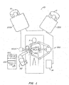
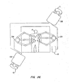
- a robotic surgical network 10 includes a master control station 200 and a slave cart 300, along with any of several other additional components to enhance the capabilities of the robotic devices to perform complex surgical procedures.
- An operator O performs a minimally invasive surgical procedure at an internal surgical site within patient P using minimally invasive surgical instruments 100.
- Operator O works at master control station 200.
- Operator O views a display provided by the workstation and manipulates left and right input devices.
- the telesurgical system moves surgical instruments mounted on robotic arms of slave cart 300 in response to movement of the input devices.
- a selectably designated "left” instrument is associated with the left input device in the left hand of operator O
- a selectably designated "right” instrument is associated with the right input device in the right hand of the operator:
- a processor of master controller 200 will preferably coordinate movement of the input devices with the movement of their associated instruments so that the images of the surgical tools 100, as displayed to the operator, appear at least substantially connected to the input devices in the hands of the operator. Further levels of connection will also often be provided to enhance the operator's dexterity and ease of use of surgical instruments 100.
- an auxiliary cart 300A can support one or more additional surgical tools 100 for use during the procedure.
- One tool is shown here for illustrative purposes only.
- a first assistant A1 is seated at an assistant control station 200A, the first assistant typically directing movements of one or more surgical instruments not actively being manipulated by operator O via master control station 200.
- a second assistant A2 may be disposed adjacent patient P to assist in swapping instruments 100 during the surgical procedure.
- Auxiliary cart 300A may also include one or more assistant input devices 12 (shown here as a simple joy stick) to allow second assistant A2 to selectively manipulate the one or more surgical instruments while viewing the internal surgical site via an assistant display 14.
- the first assistant A1 seated at console 200A views the same image as surgeon seated at console 200.
- both the instruments of cart 300 and the "assistant" instruments of cart 300A are controlled according to the same camera reference point, such that both surgeon and assistant are able to be “immersed” into the image of the surgical field when manipulating any of the tools.
- master control station 200, assistant controller 200A, cart 300, auxiliary cart 300A, and assistant display 14 may allow complex surgeries to be performed by selectively handing-off control of one or more robotic arms between operator O and one or more assistants.
- operator O may actively control two surgical tools while a third remains at a fixed position, for example, to stabilize and/or retract tissue, with the operator selectively operating the retractor or stabilizer only at designated times.
- a surgeon and an assistant can cooperate to conduct an operation without either passing control of instruments or being able to pass control of the instruments, with both instead manipulating his or her own instruments during the surgery, as will be described below with reference to Figure 26 .
- FIG. 1 depicts two surgeon consoles controlling the two cart structures, a preferred embodiment comprises only one console controlling four or more arms on two carts.
- the scope may optionally be mounted on the auxiliary cart and three tissue manipulator arms may be mounted on the main cart.
- the use of robotic systems having four or more arms will facilitate complex robotic surgical procedures, including procedures that benefit from selectable endoscope viewing angles.
- Methods for using robotic network 10 will be described in more detail following descriptions of the network components. While the network component connections are schematically illustrated in Figures 1 , 26 , and 27 , it should be understood that more complex interconnections between the various network components may be provided.
- control station 200 includes a viewer or display 202 where an image of a surgical site is displayed in use.
- a support 204 is provided on which an operator, typically a surgeon, can rest his or her forearms while gripping two master controls ( Figures 3A and 3B ), one in each hand.
- the master controls are positioned in a space 206 inwardly beyond the support 204.
- the surgeon typically sits in a chair in front of the control station 200, positions her eyes in front of the viewer 202, and grips the master controls, one in each hand, while resting her forearms on the support 204.
- the master control device generally comprises an articulate positioning arm 210A supporting orientational gimbals 210B.
- Gimbals 210B (shown most clearly in Figure 3B ) have a plurality of members or links 212 connected together by joints 214, typically by rotational joints.
- the surgeon grips the master control 210 by positioning his or her thumb and index finger over a grip actuation handle, here in the form of a grip handle or pincher formation 216.
- the surgeon's thumb and index finger are typically held on the pincher formation by straps (not shown) threaded through slots 218.
- the surgeon simply moves the pincher formation 216 to the desired end effector orientation relative to the image viewed at the viewer 202, and the end effector orientation is caused to follow the orientation of the pincher formation.
- Appropriately positioned positional sensors e.g., encoders, or potentiometers, or the like, are coupled to each joint of gimbals 210B, so as to enable joint positions of the master control to be determined as also described in greater detail herein below.
- Gimbals 210B are similarly repositioned by movement of pincher formation 216, and this positional movement is generally sensed by articulation of input arm 210A as shown in Figure 3A .
- Reference numerals 1-3 indicate orientational degrees of freedom of gimbals 210B, while numeral 4 in Figures 3A and 3B indicates the joint with which the master control and the articulated arm are connected together. When connected together, the master control 210 can also displace angularly about axis 4.
- the articulated arm 210A includes a plurality of links 220 connected together at joints 222.
- Articulated arm 210A has appropriately positioned electric motors to provide for feedback as described in greater detail below.
- appropriately positioned positional sensors e.g., encoders, or potentiometers, or the like, are positioned on the joints 222 so as to enable joint positions of the master control to be determined as further described herein below.
- Axes A, B, and C indicate the positional degrees of freedom of articulated arm 21A.
- movement about joints of the master control 210B primarily accommodates and senses orientational movement of the end effector
- movement about the joints of arm 210A primarily accommodates and senses translational movement of the end effector.
- the master control 210 is described in greater detail in U.S. Provisional Patent Application Serial No. 60/111,710 , and in U.S. Patent Application No. 09/398,507 , filed concurrently herewith (Attorney Docket No. 17516-001410).
- the orientation of the viewer relative to the master control input devices will generally be compared with the position and orientation of the end effectors relative to a field of view of the image capture device.
- the relative locations of the input devices can be derived from knowledge regarding the input device linkage joint configurations (as sensed by the joint sensors), the construction and design of the master controller structure, and in some cases, calibration measurements taken from a specific master control console system after fabrication. Such calibration measurements may be stored in a non-volatile memory of the console.
- the cart 300 is adapted to be positioned close to a surgical platform in preparation for surgery, and can then be caused to remain stationary until a surgical procedure has been completed.
- the cart 300 typically has wheels or castors to render it mobile.
- the control station 200 may optionally be positioned remote from the cart 300, but will often be in or adjacent the operating room.
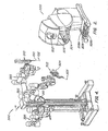
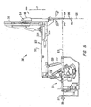
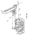
- the cart 300 carries three robotic arm assemblies.
- One of the robotic arm assemblies, indicated by reference numeral 302 is arranged to hold an image capturing device 304, e.g., an endoscope, or the like.
- Each of the two other arm assemblies 310 is arranged to carry a surgical instrument 100.
- the robotic arms are supported by positioning linkages 395, which can be manually positioned and then locked in place before (or re-positioned during) the procedure.
- the set-up joints include joint sensors which transmit signals to the processor indicating the position of the remote center of rotation.
- the manipulator arm assemblies need not be supported by a single cart. Some or all of the manipulators may be mounted to a wall or ceiling of an operating room, separate carts, or the like. Regardless of the specific manipulator structures or their mounting arrangement, it is generally preferable to provide information to the processor regarding the location of insertion/pivot points of the surgical instruments into the patient body.
- the set-up joint linkages need not have joint drive systems but will often include a joint brake system, as they will often hold the manipulators in a fixed position during some or all of a surgical procedure.
- the endoscope 304 has a viewing end 306 at a remote end of an elongate shaft.
- the elongate shaft of endoscope 304 permits it to be inserted into an internal surgical site of a patient's body.
- the endoscope 304 is operatively connected to the viewer 202 to display an image captured at its viewing end 306 on the viewer 202.
- Each robotic arm 302, 310 can be operatively connected to one or more of the master controls 210 so that the movement of instruments mounted on the robotic arms is controlled by manipulation of the master controls.
- the instruments 100 carried on the robotic arm assemblies 310 have end effectors, generally indicated at 102, which are mounted on wrist members, the wrists in turn being pivotally mounted on distal ends of elongate shafts of the instruments. It will be appreciated that the instruments have elongate shafts to permit them to be inserted into an internal surgical site of a patient's body. Movement of the end effectors relative to the ends of the shafts of the instruments is also controlled by the master controls.
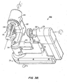
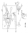
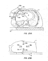
- Assembly 310 includes an articulated robotic arm 312, and a surgical instrument, schematically and generally indicated by reference numeral 100, mounted thereon.
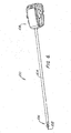
- FIG. 6 indicates the general appearance of the surgical instrument 100 in greater detail.
- the surgical instrument 100 includes an elongate shaft 104.
- the wrist-like mechanism generally indicated by reference numeral 106, is located at a working end of the shaft 104.
- a housing 108 arranged to releasably couple the instrument 100 to the robotic arm 312, is located at an opposed end of the shaft 104.
- the shaft 104 extends along an axis indicated at 109.
- the instrument 100 is typically releasably mounted on a carriage 314, which is driven to translate along a linear guide formation 316 of the arm 312 in the direction of arrows P.
- the robotic arm 312 is typically mounted on a base by means of a bracket or mounting plate 317, which is affixed to the passively movable set-up joints 395.
- Set-up joints 395 are held in a fixed configuration during manipulation of tissue by a set-up joint brake system.
- the base may be defined by the mobile cart or trolley 300, which is retained in a stationary position during a surgical procedure.
- the robotic arm 312 includes a cradle, generally indicated at 318, an upper arm portion 320, a forearm portion 322 and the guide formation 316.
- the cradle 318 is pivotally mounted on the plate 317 in gimbaled fashion to permit rocking movement of the cradle in the direction of arrows 326 as shown in Figure 5 , about a pivot axis 328.
- the upper arm portion 320 includes link members 330, 332 and the forearm portion 322 includes link members 334, 336.
- the link members 330, 332 are pivotally mounted on the cradle 318 and are pivotally connected to the link members 334, 336.
- a pivot center 349 remains in the same position relative to plate 317 with which the arm 312 is mounted.
- the pivot center 349 is positioned at an aperture or a port of entry into a patient's body when an internal surgical procedure is to be performed.
- the robotic arm 312 provides three degrees of freedom of movement to the surgical instrument 100 when mounted thereon. These degrees of freedom of movement are firstly the gimbaled motion indicated by arrows 326, pivoting movement as indicated by arrows 327 and the linear displacement in the direction of arrows P. These three degrees of freedom of movement are primarily coupled to translational degrees of movement of the end effector, although some rotational coupling may be present. Movement of the arm as indicated by arrows 326, 327 and P is controlled by appropriately positioned electrical motors which respond to inputs from an associated master control to drive the arm 312 to a required position as dictated by movement of the master control. Appropriately positioned sensors, e.g., potentiometers, or the like, are provided on the arm to determine joint positions as described in greater detail herein below.
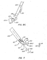
- the wrist mechanism 106 includes a wrist member 112.
- One end portion of the wrist member 112 is pivotally mounted in a clevis, generally indicated at 117, on the end 110 of the shaft 104 by means of a pivotal connection 114.
- the wrist member 112 can pivot in the direction of arrows 156 about the pivotal connection 114.
- An end effector is pivotally mounted on an opposed end of the wrist member 127.
- the end effector 102 is in the form of, e.g., a clip applier for anchoring clips during a surgical procedure. Accordingly, the end effector 102 has two elements 102.1, 102.2 together defining a jaw-like arrangement.
- the end effector can be in the form of any surgical tool having two members which pivot about a common pivotal axis, such as scissors, pliers for use as needle drivers, or the like. Instead, it can include a single working member, e.g., a scalpel, cautery electrode, or the like.
- Non-articulated tools may also be used, including tools for aspiration and/or irrigation, endoscopes, or the like.
- a tool other than a clip applier is required during the surgical procedure, the tool 100 is simply removed from its associated arm and replaced with an instrument bearing the required end effector, e.g., a scissors, or pliers, or the like.
- the end effector 102 is pivotally mounted in a clevis, generally indicated by reference numeral 119, on an opposed end of the wrist member 112, by means of a pivotal connection 160.
- Elements 102.1, 102.2 are angularly displaceable about the pivotal connection 160 toward and away from each other as indicated by arrows 162, 163. It will further be appreciated that the elements 102.1, 102.2 can be displaced angularly about the pivotal connection 160 to change the orientation of the end effector 102 as a whole, relative to the wrist member 112.
- each element 102.1, 102.2 is angularly displaceable about the pivotal connection 160 independently of the other, so that the end effector 102, as a whole, is angularly displaceable about the pivotal connection 160 as indicated in dashed lines in Figure 7 .
- the shaft 104 is rotatably mounted on the housing 108 for rotation as indicated by the arrows 159.
- the end effector 102 has three degrees of freedom of movement relative to the arm 112 in addition to actuation of the end effector, preferably namely, rotation about the axis 109 as indicated by arrows 159, angular displacement as a whole about the pivot 160 and angular displacement about the pivot 114 as indicated by arrows 156.
- the three degrees of freedom of movement of instrument 100 are primarily coupled to orientational degrees of freedom of movement of the end effector. This is somewhat a simplification, as movement about these three axes will result in some change in position of the end effector. Similarly, movement about the above-described translational axes may cause some changes in orientation.
- orientational movement of the end effector like translational movement, is controlled by appropriately positioned electrical motors which respond to inputs from the associated master control to drive the end effector 102 to a desired position as dictated by movement of the master control.
- appropriately positioned sensors e.g., encoders, or potentiometers, or the like, are provided to determine joint positions as described in greater detail herein below.
- the actuation or movement of the end effectors relative to each other in the directions of arrows 62, 63 is not regarded as a separate degree of freedom of movement.
- Tissue stabilizer end effectors 120a, b, and c are illustrated in Figures 8A-C .
- Tissue stabilizers 120 may have one or two end effector elements 122 that preferably are pivotally attached to the distal end of the shaft or wrist of a surgical instrument and are moveable with respect to one another, and that preferably comprise tissue-engaging surfaces 124.
- the tissue-engaging surfaces optionally include protrusions, ridges, vacuum ports, or other surfaces adapted so as to inhibit movement between the engaged tissue and the stabilizer, either through pressure applied to the engaged tissue or vacuum applied to draw the tissue into an at least partially stabilized position, or a combination of both pressure and vacuum.
- the ideal tissue engaging surface will constrain and/or reduce motion of the engaged tissue in the two lateral (sometimes referred to as the X and Y) axes, along the tissue-engaging surface, and the stabilizer configuration and engagement with the tissue will at least partially decrease motion normal to the surface.
- Other configurations for traditional stabilizers are known to those of skill in the art, such as the Octopus II of Medtronic, Inc. and various HeartPort, Inc. and CardioThoracic Systems stabilizers having multipronged and doughnut configurations. These manners of contacting tissue allow stabilizers 120 to firmly engage a moving tissue such as a beating heart of a patient and reduce movement of the tissue adjacent the stabilizer.
- an opening 126 may be formed in an individual stabilizer element 122, and/or between independently moveable end effector elements.
- stabilizer 120b includes cooperating tissue grasping surfaces 128 disposed between stabilizer end effector elements 122. This allows the stabilizer to grasp tissues, providing a dual function robotic stabilizer/grasper tool.
- Stabilizer 120b may be used, for example, as a grasper while harvesting and/or preparing an internal mammary artery (IMA) for a coronary artery bypass graft (CABG) procedure, and/or to hold the IMA during formation of the anastomosis on the stabilized beating heart.
- IMA internal mammary artery
- CABG coronary artery bypass graft
- tissue stabilizers 120 will have a sufficiently small profile, when aligned with shaft 104 of instrument 100, to allow the stabilizer to advance axially through a cannula.
- Similar (or modified) end effectors having high friction tissue-engaging surfaces may be used as retractors to hold tissue clear of a surgeon's line of sight during a procedure.
- each stabilizer may comprise an irrigation port 125, the port preferably in fluid communication with a lumen integrated into the shaft of the stabilizer tool. While an irrigation and/or aspiration capability is particularly beneficial when incorporated into a stabilizer, such capabilities may also be incorporated into the shaft of any robotic surgical tool, as desired.
- the port system comprising a lumen preferably situated inside the shaft of the stabilizer and extending out of an aperture or port in the distal portion of the shaft, may be used to perform a number of tasks during a surgical procedure (e.g., a beating heart procedure) in which stabilization of tissue is desired.
- Those tasks may include removing undesired fluid from the surgical site (either through suction to outside the patient's body), blowing the fluid into some other portion of the surgical site, and/or delivering fluid (such as spray humidified carbon dioxide) to clear the surgical site of material (such as body fluids which might otherwise interfere with the surgeon's view).
- fluid such as spray humidified carbon dioxide
- at least the distal portion of the port system is flexible to permit bending.
- the exemplary port structure will be malleable or plastically deformable enough that it will hold its position when repositioned.
- the stabilizer is inserted with the distal external portion of the irrigation device preferably flush with the shaft of the stabilizer.
- the operator may reposition the irrigation port distal end with one of the other surgical manipulators by grasping the port structure and moving it to a desired location and/or orientation relative to shaft 104, wrist 106, or end effector element 122 (depending on the structure to which the port is mounted).
- the device may remain in that location for the duration of the surgery, or may be moved around as desired.
- the device also may be extendable from/retractable into the stabilizer shaft, so that the distal end can be moved towards or away from the surgical site itself, as desired.
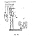
- Auxiliary cart 300A includes a simple linkage 350 with sliding joints 352 which can be releasably held in a fixed configuration by latches 354.
- Linkage 350 supports an auxiliary remote center manipulator arm 302A having a structure similar to arm 302 used to support the endoscope on cart 300. (See Figure 4 .)
- the linkage structure of auxiliary arm 302A is described more fully in co-pending U.S. Patent Application Serial No. 60/112,990, filed on December 16, 1998 .
- auxiliary arm 302A effectively includes a parallel linkage mechanism providing a remote center of spherical rotation 349 at a fixed location relative to base 317, similar to that described above with reference to arm 312 in Figure 5 .
- this arm is described as preferably being of different structure that other instrument manipulator arms also described herein, it should be understood that a other manipulator arm can also be used either to support an endoscope or to serve as the fourth arm on the auxiliary cart 300A.
- Sliding joints 352 and wheels 356 (which can also be releasably locked in a fixed configuration by latches 354) allow remote center or fulcrum 349 to be positioned at an insertion point into a patient body using translational movement along X, Y, and Z axes.
- Auxiliary arm 302A may optionally be actively driven so as to translationally position a shaft of a surgical instrument within a patient body. Alternatively, auxiliary arm 302A may be used as a passive manipulator arm.
- Auxiliary arm 302A (like all manipulator arms of the robotic network) preferably includes a repositioning configuration input device or button 358, ideally disposed on a manual positioning handle 360.
- auxiliary cart 300A may be used to support a surgical instrument such as an endoscope, a stabilizer, a retractor, or the like, even if not actively driven under direction of an input device.
- Manual repositioning of the supported surgical instrument will generally be performed by an assistant under the direction of a surgeon in charge of the surgical procedure.
- the brake or motor drive systems inhibiting movement of the instruments can be safely overridden using manual force without damaging the robotic system.
- the override force will be sufficient to inhibit inadvertent movement from accidental bumping, interference between manipulators, and the like.
- Auxiliary arm 302A and arm 302 used to support endoscope 304 need not necessarily include a drive system for articulating a wrist and/or end effectors within the patient body, unless, e.g., a wrist is to be used in connection with a stabilizer to improve positioning of the particular tissue to be stabilized.
- arm 302 may optionally be replaced by arm 312.
- a manual tool articulation bracket 370 may be used to mount the tool 100 to auxiliary arm 302A.
- the manual tool bracket 370 is illustrated in Figures 9C-9E .
- bracket 370 comprises a plate 372 with sidewalls which fittingly receive housing 108 of tool 100.
- Discs 374 have drive surfaces which drivingly engage the drive system of tool 100 so as to rotate shaft 104 about its axis, articulate the end effector about the wrist, and move the first and second end effector elements, as described above.
- bracket 372 comprises a polymer
- knobs 376 and nuts 378 may be polymeric and/or metallic.
- Washer 379 may comprise a low friction polymer, ideally comprising a PTFE such as Teflon TM , or the like.
- the surgeon views the surgical site through the viewer 202.
- the end effector 102 carried on each arm 312, 302, 302A is caused to perform movements and actions in response to movement and action inputs of its associated master control.
- images of the end effectors are captured by the endoscope together with the surgical site and are displayed on the viewer so that the surgeon sees the movements and actions of the end effectors as he or she controls such movements and actions by means of the master control devices.
- the relationship between the end effectors at the surgical site relative to the endoscope tip as viewed through the viewer and the position of the master controls in the hands of the surgeon relative to the surgeon's eyes at the viewer provides an appearance of at least a substantial connection between the master controls and the surgical instrument for the surgeon.
- the processor of master control station 200 and/or assistant control station 200A will generally map the internal surgical worksite viewed by the endoscope onto the master controller work space in which the operator and/or assistant moves his or her hands.
- the position of the arms holding the surgical tools relative to the arm holding the endoscope in use may be used to derive the desired coordinate transformations so as to provide the desired level of substantial connectedness, as more fully explained in co-pending U.S. Patent Provisional Application Serial No. 60/128,160 .
- a tool is to be viewed through an endoscope, and the tool and endoscope are supported by independent support structures (for example, when viewing a tool supported by arm 312 within the internal surgical site via an endoscope supported by auxiliary cart 300A) it is particularly beneficial to have a known orientation between the two independent support structures to allow the desired transformations to be derived.
- This may be provided, for example, by ensuring that the base structure of cart 300 is accurately parallel to the base structure of auxiliary cart 300A. As positional transformations and modifications are relatively straightforward when orientations are accurately aligned, this allows a processor to provide substantial connection despite the separately mounted robotic network components.
- telesurgical robotic network 10 The operation of telesurgical robotic network 10 will first be explained with reference to interaction between master control station 200 and cart 300. Many of the aspects of this interaction appear in the interactions among the remaining network components.
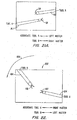
- the Cartesian space coordinate system is indicated generally by reference numeral 902.
- the origin of the system is indicated at 904.
- the system 902 is shown at a position removed from the endoscope 304.
- the origin 904 is conveniently positioned at the viewing end 306.
- One of the axes, in this case the Z-Z axis, is coincident with the viewing axis 307 of the endoscope. Accordingly, the X-X and Y-Y axes extend outwardly in directions perpendicular to the viewing axis 307.
- the reference plane defined by the X-X and Y-Y axis is angularly displaced together with the endoscope.
- each fulcrum 349 is positioned at a port of entry into the patient's body.
- movements of the end effectors at the surgical site is caused by angular displacements about each fulcrum 349.
- the location of the fulcrums may be sensed using joint sensors of the set-up joints, or using a variety of alternative position sensing systems.
- the coordinates in the X-X and Y-Y plane of the Cartesian coordinate system 902 are determined. It will be appreciated that these (X,Y) coordinates of each fulcrum 349 can vary depending on the chosen entry ports to the surgical site. The location of these entry ports can vary depending on the surgical procedure to be performed. It will further be appreciated that the (X,Y) coordinates of each fulcrum 349 can readily be determined with reference to the coordinate system 902 by means of the position sensors at the various pivot points on each robotic arm 112 since the endoscope 304 and the arms 310 are mounted on the same cart 300.
- the endoscope arm 302 is also provided with appropriately positioned positional sensors.
- the position of the coordinate system 902 can be determined relative to any arbitrary point in space by means of the positional sensors on the endoscope arm 302 and the positions of each fulcrum relative to the same arbitrary point can readily be determined by means of the positional sensors on each robotic arm 112.
- the positions of each fulcrum 349 relative to the coordinate system 902 can then be determined by means of routine calculation.
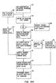
- a control system defining a control loop which links master control inputs to end effector outputs, and vice versa for feedback is schematically indicated by reference numeral 400.
- Master control inputs and corresponding end effector outputs are indicated by arrows AB and end effector inputs and corresponding master control outputs in the case of feedback is indicated by arrows BA.
- positions sensed by the encoders on the master which relate to joint positions are referred to as “joint space” positions.
- positions determined by these sensors are also referred to as “joint space” positions.
- the robotic arm and wrist mechanism will be referred to as the slave in the description which follows.
- references to positions and positioned signals may include orientation, location, and/or their associated signals.
- forces and force signals may generally include both force and torque in their associated signals.
- the system 400 will be described from an initial condition in which the master is at an initial position and the slave is at a corresponding initial position. However, in use, the slave tracks master position in a continuous manner.
- the master is moved from the initial position to a new position corresponding to a desired position of the end effector as viewed by the surgeon in the image displayed on the viewer 202.
- Master control movements are input by a surgeon at 402, as indicated by arrow AB1 by applying a force to the master control at 404 to cause the master control to move from its initial position to the new position.
- signals e m from the encoders on the master is input to a master input controller at 406 as indicated by arrow AB2.
- the signals e m are converted to a joint space position ⁇ m corresponding to the new position of the master.
- the joint space position ⁇ m is then input to a master kinematics converter 408 as indicated by arrow AB3.
- the joint position ⁇ m is transformed into an equivalent Cartesian space position x m . This is optionally performed by a kinematic algorithm including a Jacobian transformation matrix, inverse Jacobian (J- 1 ), or the like.
- the equivalent Cartesian space position x m is then input to a bilateral controller at 410 as indicated by arrow AB4.
- Position comparison and force calculation may, in general, be performed using a forward kinematics algorithm which may include a Jacobian matrix.
- Forward kinematics algorithm generally makes use of a reference location, which is typically selected as the location of the surgeon's eyes. Appropriate calibration or appropriately placed sensors on console 200 can provide this reference information. Additionally, the forward kinematics algorithm will generally make use of information concerning the lengths and angular offsets of the linkage of the master input device 210. More specifically, the Cartesian position x m represents the distance of the input handle from, and the orientation of the input handle relative to, the location of the surgeon's eyes. Hence, x m is input into bilateral controller 410 as indicated by AB4.
- the slave location is also generally observed using sensors of the slave system.
- the encoder signal e s are read from the slave joint sensors at 416 as indicated by BA2, and are then converted to joint space at step 414.
- the joint space position of the slave is also subjected to a forward kinematics algorithm at step 412.
- the forward kinematics algorithm is preferably provided with the referenced location of tip 306 of endoscope 304.
- this kinematics algorithm incorporates information regarding the lengths, offsets, angles, etc., describing the linkage structure of patient cart 300, set-up joints 395, and robotic manipulator arms 310, so that the slave Cartesian position x s transferred at BA4 is measured and/or defined relative to the endoscope tip.
- the new position of the master x m in Cartesian space relative to the surgeon's eyes is compared with the initial position x s of the instrument tip in Cartesian space relative to the camera tip.
- This relationship is depicted in Fig. 10 showing the triangle connecting the surgeon's eye and the master controllers in the hands of the surgeon, as well as the triangle coupling camera tip 306 and the end effectors of tools 104.
- the comparison of these relative relationships occurring in controller 410 can account for differences in scale between the master controller space in which the input device is moved as compared with the surgical workspace in which the end effectors move. Similarly, the comparison may account for possible fixed offsets, should the initial master and slave positions not correspond.
- the new position x m of the master in Cartesian space is compared with the initial position of the slave, also in Cartesian space.
- the positions of the master and slave in Cartesian space are continually updated in a memory.
- the initial position of the slave in Cartesian space is downloaded from the memory so as to compare it with the new position of the master in Cartesian space.
- the initial position of the slave in Cartesian space was derived from the joint space position of the slave when both the master and the slave were at their initial positions.
- no positional deviation results from the comparison at 410. In such a case no signals are sent from 410 to cause movement of the slave or the master.
- a force ⁇ s in Cartesian space is computed at 410 which is necessary to move the slave position in Cartesian space to a new position corresponding to the new position of the master x m in Cartesian space.
- This computation is typically performed using a proportional integral derivative (P.I.D.) controller.
- P.I.D. proportional integral derivative
- This force ⁇ s is then input to a slave kinematics converter 412 as indicated by arrow AB5.
- Equivalent joint torques ⁇ s are computed in the slave kinematics module, typically using a Jacobian transpose method. This is optionally performed by a Jacobian Transpose (J T ) controller.
- the torques ⁇ s are then input to a slave output converter at 414 as indicated by arrow AB6.
- currents is are computed. These currents is are then forwarded to the electrical motors on the slave at 416 as indicated by arrow AB7.
- the slave is then caused to be driven to the new position x e which corresponds to the new position into which the master has been moved.
- control steps involved in the control system 400 as explained above are typically carried out at about 1300 cycles per second or faster. It will be appreciated that although reference is made to an initial position and new position of the master, these positions are typically incremental stages of a master control movement. Thus, the slave is continually tracking incremental new positions of the master.
- the control system 400 makes provision for force feedback.
- the slave typically the end effector
- an environmental force ⁇ e at the surgical site e.g., in the case where the end effector pushes against tissue, or the like
- ⁇ e an environmental force
- the slave is tracking movement of the master as described above and the slave pushes against an object at the surgical site resulting in an equal pushing force against the slave, which urges the slave to move to another position, similar steps as described above take place.
- the surgical environment is indicated at 418 in Figure 11 .
- an environmental force ⁇ e is applied on the slave, such a force ⁇ e causes displacement of the end effector.
- This displacement is sensed by the encoders on the slave 416 which generate signals e s .
- Such signals e s are input to the slave input converter 414 as indicated by arrow BA2.
- a position ⁇ s in joint space is determined resulting from the encoder signals e s .
- the joint space position ⁇ s is then input to the slave kinematics converter at 412 and as indicated by arrow BA3.
- a Cartesian space position x s corresponding to the joint space position ⁇ s is computed and input to the bilateral controller at 410 as indicated by arrow BA4.
- the Cartesian space position x s is compared with a Cartesian space position x m of the master and a positional deviation in Cartesian space is computed together with a force ⁇ m required to move the master into a position in Cartesian space which corresponds with the slave position x s in Cartesian space.
- the force ⁇ m is then input to the master kinematics converter at 408 as indicated by arrow BA5.
- desired torque values ⁇ m are determined at 408. This is typically performed by a Jacobian Transpose (J T ) controller.
- the torque values are then input to the master output converter at 406 as indicated by arrow BA6.
- master electric motor currents i m are determined from the torque values ⁇ m and are forwarded to the master at 404 and as indicated by arrow BA7 to cause the motors to drive the master to a position corresponding to the slave position.
- bilateral controller 410 may output a Cartesian slave position command x sd at AB5 to the kinematics module 412, with the Cartesian slave position command indicating the desired position of the slave.
- Kinematics algorithm module 412 may then use, for example, an inverse Jacobian algorithm to determine a desired joint space position ⁇ sd which can be compared against the initial joint space position of the slave ⁇ s . From this comparison, joint torques may be generated to compensate for any positioning errors, with the joint torques passed via AB6 to the slave input/output module 414 as described above.
- control system 400 may couple actuation of the master handle (in the exemplary embodiment, variation of the gripping angle defined between grip members 218 as shown in Fig. 3B ) to articulation of the end effector (in the exemplary embodiment, opening and closing the end effector jaws by varying the end effector angle between end effector elements 102.1, 102.2 as illustrated in Fig. 7 ) in the matter described above, by including the master grip input and the end effector jaw actuation in the joint and Cartesian position effectors, equivalent torque vectors, and the like, in the calculations which have been described.
- additional controllers or controller modules may be active, for example, to provide friction compensation, gravity compensation, active driving of redundant joint linkage systems so as to avoid singularities, and the like.
- These additional controllers may apply currents to the joint drive systems of the master and slaves.
- the additional functions of these added controllers may remain even when the master/slave control loop is interrupted, so that termination of the master/slave relationship does not necessarily mean that no torques are applied.
- FIG. 11A-11D An exemplary controller block diagram and data flow to flexibly couple pairs of master controllers with manipulator arms are shown in Figs. 11A-11D .
- the operator 402 manipulates manipulators 404, here inputting actuation forces against both the left and right master manipulators ⁇ h (L, R).
- both left and right positions of the master input devices will also be accommodated by the control system, as will forces and positions of four or more slave manipulator arms ⁇ e (1, 2, 3, and 4), x e (1, 2, 3, and 4). Similar left, right, and slave notations apply throughout Figs. 11A-11D .
- the encoder increments from each joint of the master input devices 404 and the slave manipulators 416 are all input into a servocontrol input pre-processor SCI.
- this information may be provided in an alternative format, such as with an analogue signal (optionally providing absolute position indication) from a Hall effect transducer, a potentiometer, or the like.
- pre-processor SCI may include one or more accumulators 1002 as illustrated in Fig. 11B .
- Positive and/or negative encoder increments are counted between servocycle transfer requests 1004, which are provided from a servo timing generator STG are accumulated in a first register 1006. After receipt of transfer request 1004, the accumulated encoder increments from throughout the servocycle are transferred to second register 1008.
- the transfer request is preferably offset from an encoder increment clock so as to avoid inadvertent encoder reading errors during servocycle data transfer.
- an asynchronous transfer request/encoder increment sample rate is preferably provided, as illustrated in Fig. 11C .
- the sample rate will often be higher than the rate at which the encoder can produce increments, and the accumulators will generally hold incremental position information for all encoder-equipped freely moveable joints of the input and slave manipulators over a servocycle, the servocycle preferably having a frequency of over 900 Hz, more preferably having a frequency of 1,000 Hz or more, often having a frequency of at least about 1,200 Hz, and ideally having a frequency of about 1,300 Hz or more.
- an accumulator 1002 will be included in pre-processor SCI for each encoder of the master input devices 404 and slave manipulators 416.
- Each encoder accumulator will preferably accommodate at least a 12-bit joint position signal, and in many cases will accommodate a 14-bit joint position signal.
- analogue position signals are provided, they will typically be converted to digital signals at or before storage in the pre-processor SCI, with as many as 48 joint signals or more being provided in the exemplary pre-processor.
- joint positional information e m , e s for a particular master input device 404/slave manipulator 416 pair is retrieved in response to a servointerrupt signal 1010 from the servo timing generator STG.
- the control processor CTP may transform these joint position signals to the desired coordinate reference frame, or may alternatively transfer this information in joint space on to the bilateral controller CE1 for conversion to the desired reference frame. Regardless, the position is preferably transmitted from the control processor CTP to the bilateral controller CE1 using a direct memory access DMA controller or other high-speed data transmission system.
- the controller processes the positional information, comparing the end effector positions in the surgical workspace with the input device positions (including both location and orientation) in the master controller workspace.
- the surgical and controller se workspaces may be scaled and positioned relative to each other as desired, often using positional information provided by the sensors of the set-up joints, and incorporating calibration and/or assembly information of the master control console so as to identify the location and/or orientation of the master input device relative to the viewer.
- an appropriate coordination transformation may be derived so as to mathematically couple the master space of the master control workstation and the slave space in the surgical environment.
- the information on both the master and slave linkages in structure may be based on a model of these linkage and support structures, on design specifications for the linkage and support structures, and/or on measurements of individual linkages, which may be stored in a non-volatile memory of the slave and/or master control, such as by burning calibration information into a memory of the appropriate structure.
- a servocycle time is used by the controller CE1 to calculate appropriate high-level instructions for the master and slave systems.
- the results of these calculations are transferred to control processor CTP via yet another DMA interrupt 1014.
- These high-level commands typically in the form of desired forces to be applied on the master and slave ⁇ m , ⁇ s in a suitable reference frame such as a Cartesian coordinate system are converted by the control processor CTP to desired motor current signals, which are directed to the appropriate motors by post-processor SCO.
- Fig. 11A While the pre- and post-processors, timing generator, control processor, and controllers are illustrated schematically in Fig. 11A as separate blocks, it should be understood that some or all of these functional components may be combined, for example, on a single processor board, or that multiple processor boards may be used with the functions of one or more of these components being separated on to separate processors.
- the first controller CE1 is processing the position and other information associated with the first master/slave pair
- the pre- and post-processors and control processor are processing and transferring data for use by the second and third controllers CE2, CE3.
- the individual controllers have asynchronous input and output times. It should be understood that more than three controllers may be provided for additional master/slave pairs.
- the first and second controllers CE1 and CE2 might be dedicated to left and right hand inputs from the surgeon, while the third controller CE3 may be used to move the endoscope using the left and/or right input device, or any other desired input system.
- servo timing generator STG includes a memory storing the master/slave pair assignments 1016. These pair assignments are communicated to the pre- and post-processors SCI, SCO, so that the information transferred to and from the control processor CTP is appropriate for the controller, and so that the commands from the appropriate controller are properly understood and transmitted to the drive system for the appropriate joints. Reallocation of the master/slave pair assignments is transmitted to the timing generator STG from the control processor CTP, and is then communicated from the timing generator to the pre-and post-processors during an intermittent initialization phase, which may also be used to set up appropriate processor time intervals. Alternatively, the time intervals may be fixed.
- the flexible master/slave pairing controller of Fig. 11A is still a simplification, and an appropriate controller will include a number of additional systems.
- the control system may check for changes in pair assignments, for example, during data transfer to and/or from the camera controller.
- pair assignments may be reviewed during and/or after a tool change, during a left/right tool swap, when handing off tools between two different master controllers, when the system operator requests a transfer, or the like.
- control system of Figs. 11A-11D may accommodate flexible tool mountings on the various manipulators.
- the first and second controllers CE1, CE2 may be used to manipulate tools for treating tissue, while the third controller CE3 is dedicated to tool movements using inputs from both master input devices.
- the pair assignments for the three controllers may be revised to reflect this change without otherwise altering the system operator's control over the system.
- the exemplary embodiment includes a single master bus and a single slave bus, one or both of these individual busses may be replaced with a plurality of busses, or they may be combined into a single bus.
- the exemplary servocycle time for an individual control pair is preferably about 1,000 msec or less, and ideally about 750 msec or less, the use of higher speed processing equipment may provide servocycle times which are significantly faster.
- the master/slave interaction between master control station 200 and cart 300 is generally maintained while the operator O is actively manipulating tissues with surgical instruments associated with his or her left and right hands. During the course of a surgical procedure, this master/slave interaction will be interrupted and/or modified for a variety of reasons.
- the following sections describes selected interruptions of the master/slave control interaction, and are useful for understanding how similar interruptions and reconfigurations of the telesurgical robotic network may be provided to enhance the capabilities of the overall robotic system.
- the exemplary interruptions include "clutching" (repositioning of a master control relative to a slave), repositioning of an endoscope, and a left-right tool swap (in which a tool previously associated with a master control input device in a right hand of a surgeon is instead associated with an input device in a left hand of the surgeon, and vice versa ). It should be understood that a variety of additional interruptions may occur, including during removal and replacement of a tool, during manual repositioning of a tool, and the like.
- the surgeon may wish to translationally reposition one or both of the master controls relative to the position or positions of a corresponding end effector or effectors as displayed in the image.
- the surgeon's dexterity is generally enhanced by maintaining an ergonomic orientational alignment between the input device and the image of the end effector.
- the surgeon may reposition the master relative to the end effector by simply interrupting the control loop and re-establishing the control loop in the desired position, but this can leave the end effector in an awkward orientation, so that the surgeon repeatedly opens the control loop to reorient the end effectors for each translational repositioning.
- the ergonomic rotational alignment between input devices and the images of the end effectors can be preserved after the master control or controls have been repositioned by a modified clutching procedure, which will now be described with reference to Figures 12 and 13 .
- FIG. 12 a block diagram indicating the repositioning of one of the master controls is indicated generally by reference numeral 450 and will now be described. It will be appreciated that both master controls can be re-positioned simultaneously. However, for ease of description, the repositioning of a single master control will be described.
- the surgeon causes the control loop 400 linking master control movement with corresponding slave movement to be interrupted. This is accomplished by activation by the surgeon of a suitable input device, labeled "Depress Master Clutch Button" at 452 in Figure 12 . It has been found that such a suitable input device can advantageously be in the form of a foot pedal as indicated at 208 in Figure 2 .
- any suitable input can be provided such as voice control input, a finger button, or the like. It is advantageous to provide an input device which does not require the surgeon to remove his or her hands from the master controls so as to preserve continuity of master control operation.
- the input device can be incorporated on the master control device itself instead of having a foot pedal.
- the control loop 400 between master and slave is interrupted.
- the slave is then locked in its position, in other words in the position in which it was at immediately before the foot pedal was depressed.
- the link 410 in the control system 400 between master and slave is interrupted.
- the position in joint space of the slave immediately before depression of the foot pedal is recorded in a memory of a slave joint controller indicated at 420 in dashed lines.
- the encoders on the slave relay signals to 414 where a new joint space position for the slave is computed and forwarded to the slave joint controller 420 as indicated by arrow BA9.
- This new joint space position is compared with the joint space position in the memory, and joint space deviations are determined. From this joint space deviation, torques are computed to return the slave to the joint position as recorded in the memory. These torques are relayed to 414 as indicated by arrow AB9 where corresponding electric motor currents are determined which are forwarded to the slave motors to cause it to restore its joint space position.
- the slave position is servo locked.
- the joint space position input of the master control as indicated by ⁇ a is converted from joint space to Cartesian space at 406. From this conversion, a Cartesian space position x a of the master is obtained.
- the position in Cartesian space of the master immediately before activation of the foot pedal is recorded in a memory at 424 and is indicated by x d .
- the current position x a of the master as it moves to its new position is compared with the recorded position x d at 456 to obtain error signals, which correspond to positional deviations of current master position in Cartesian space when compared with the recorded position x d in Cartesian space.
- deviations or errors are input to a feedback controller at 426 to determine a feedback force to return the master to a position corresponding to the recorded position x d .
- the components of the feedback force which corresponds to translational movement are zeroed at 428.
- translational feedback force components are zeroed and only orientational force components are forwarded from 428.
- the orientational force components are then converted to corresponding torques at 408, which are then input to 406 (in Figure 11 ) to determine currents for feeding to the electric motors on the master to cause its orientation to be urged to remain in a condition corresponding to the orientation determined by x d .
- the orientation at the position x d corresponds to the orientation of the slave since the slave continuously tracks the master and the positions were recorded in memory at the same time. Since the translational forces were zeroed, the translational movement of the master is caused to float enabling the surgeon to translate the master to a new, desired position. Such translational floating may alternatively be provided by a variety of other methods.
- the translational gains of controller 426 may be set to zero.
- the translational elements of memory 424 may be continually reset to be equal to the input values x a , so that the difference between the measured position and the stored position is zero. It should also be understood that despite the zeroing of the translational terms, additional controller functions such as friction compensation, gravity compensation, or the like, may remain unaltered.
- the foot pedal when the master controls have been moved to their desired position the foot pedal is released.
- the translational deviations relating to the new position of the master control relative to its associated slave is incorporated into 410 to define a new Cartesian space position at which the slave position corresponds to the master position.
- the translational derivations may be incorporated in the fixed offsets described above, preferably using the algorithm described herein to avoid inadvertent sudden movements or forces.
- FIG. 19 a block diagram illustrating the steps involved in re-connecting the control system 400 between the master and the slave is generally indicated by reference numeral 470.
- the first step involving in re-connecting control between the master and the slave is to determine whether or not the master orientation is sufficiently close to the slave orientation. It will be appreciated that it could happen that during repositioning of the master as described above, the surgeon could be urging the pincher formation on the master away from its orientationally aligned position relative to the slave. Should re-connection of control between master and slave then occur, it could result in reactive motion by the slave resulting from the urging force applied by the surgeon on the pincher formation. This reactive motion by the slave could cause unnecessary damage to organs, or tissue, or the like, at the surgical site and should be avoided. Accordingly, at 472 the orientation of master and slave is compared.
- the master alignment algorithm may be executed as described hereinbelow with reference to Fig. 18 .
- the slave orientation is optionally snapped with the master orientation in Cartesian space as indicated at 474. Once the orientation is snapped, the Jacobian Inverse controller on the slave is enabled as indicated at 476. Thereafter, the Cartesian force reflection commands and gains are downloaded as indicated at 478.
- the snapping of the slave orientation to the master orientation means that the orientational offsets in bilateral controller 410 are reset to zero, so that the master and slave orientations begin tracking each other.
- the control system 410 is reconfigured to normal bilateral control, preferably using a Jacobian inverse, as indicated at step 476.
- the appropriate commands and gains are downloaded as indicated at step 478.
- the orientational offsets in bilateral controller 410 may alternatively be slowly and smoothly reduced to zero, thereby providing a smoother transition between operating modes. This may be effected by, for example, filtering the orientational offset values to zero.
- control system 400 may include potentially substantially instantaneous changes in configuration or perimetric values of the control system.
- interrupting or opening the loop of bilateral controller 410, enabling master Cartesian controller 422, resetting memory 424 or the controller gains in P.I.D. controller 426 might be performed by substantially instantaneously changing the perimetric values and/or configurations.
- Such instantaneous changes may be fundamentally different than normal master/slave operation, where the computations are continually repeated using fixed perimetric values and operational configurations, with only the sensor readings changing.
- the relevant control system mode transitions typically involve a configuration change, a change in a fixed memory value, or the like.
- bilateral controller 410 makes use of fixed offsets in its memory.
- Controllers 420, 422, and 560 also contain fixed commands in their memories.
- the no-jerk algorithm which generally decreases and/or eliminates rapid inadvertent movement of the master or slave, utilizes known sensor readings, configuration information, and memory values immediately before a control system operating mode transition. By assuming that sensor readings will remain predictable, changing only slightly during the controller mode transition, the no-jerk algorithm computes desired memory reset values by also taking into account the known end values or configuration, and by synchronizing the change in values so as to promote smooth motor current changes during the mode transition. For some uses, the no-jerk algorithm my reduce or eliminate sudden changes in motor torques by using pre-transition (and optionally filtered) motor currents or joint torque values in place of or in combination with the pre-transition sensor configuration and memory values as inputs.
- pre-transition configuration, perimetric values, and memory values are used, together with sampled pre-transition sensor values 702 to compute pre-transition joint torques at step 704.
- these pre-transition joint torques may be directly observed, optionally with filtering, at step 706.
- post-transition joint torque values are forced to match the pre-transition joint torque values at step 708.
- the post-transition effective feedback gains may be determined at step 712. These post-transition effective feedback gains may be inverted and used together with the post-transition joint torques to calculate a desired post-transition error signal at step 714.
- the post-transition sensor values may be predicted at step 716. These post-transition sensor values may be estimated by assuming that smooth sensor readings will be provided, and knowing the time it takes to effect transition.
- the desired post-transition error signal and predicted sensor values may be used to derive a desired post-transition command signal at step 718.
- the post-transition command signal will generally determine the desired memory or offset value through calculations performed at step 720.
- This post-transition memory or offset value is reset in synchronization with the transition at step 722.
- a block diagram indicating steps involved in repositioning a slave relative to its associated master is generally indicated by reference numeral 500.
- a suitable input is activated to interrupt the control loop 400 between the master and the slave.
- Such a suitable input can be in the form of a button on the robotic arm as indicated at 480 in Figure 5A . Depressing such a button to interrupt the control loop 400 is indicated by the term "Depress Slave Clutch Button" at 504 in Figure 14 .
- the button is depressed, the control between master and slave is interrupted to cause the translational movements of the slave to float while the orientation of the end effector is locked as indicated at 502 in Figure 14 .
- the floating joints may optionally still have some forces imposed against the joint by their associated joint-drive systems. More specifically, as described more fully in co-pending U.S. Patent Application Serial No. 09/287,513 , the controller may impose actuation forces on the master and/or slave so as to compensate for gravity, friction, or the like. These compensation forces may be maintained on the floating joint or joints even when the control link for actuating the joint is otherwise open.
- the torques thus determined which relate to translational torques of the slaves are zeroed at 466 to permit the slave translational movements to float.
- the torques corresponding to orientational movement are not zeroed.
- any environmental forces on the end effector urging an orientational position change are fed back to the end effector to cause it to retain its orientation.
- the orientation of the end effector relative to the end of the instrument shaft 104 is locked in position.
- the orientation of the end effector does not change relative to the end of the shaft, it does change in position in Cartesian space as a result of translational position change.
- zeroing of the outer joint torques at step 466 may be effected by a variety of methods, including zeroing of the appropriate gains in P.I.D. controller 464, continually updating the appropriate elements in memory 460 so as to compute a zero error signal at comparison 462, or the like.
- slave transitional forces may be zeroed in Cartesian space (analogous to the master clutching algorithm described with reference to Figs. 12 and 13 ).
- control system 400 and/or bilateral controller 410 may be interrupted only for translational motions, locking the master translational position and allowing the slave to float in transnational position, all while connecting the master orientation to the slave orientation. Once the slave is at the desired position the button is released as indicated at 510 in Figure 14 .
- the master orientation is re-aligned with the slave orientation as indicated at 512.
- the re-aligning of the orientation of the master and slave is now described with reference to Figure 18 .
- the steps involved in such realignment are generally indicated by reference numeral 550.
- the slave position ⁇ s in joint space is read.
- the position ⁇ s is then converted to a position x s in Cartesian space at 554 using slave forward kinematics.
- the desired orientation of the master is set to equal the slave orientation in Cartesian space.
- x m the master orientational position in Cartesian space is set to equal x s , the slave orientational position in Cartesian space.
- inverse master kinematics is employed to determine the master joint position ⁇ m in joint space which corresponds to x m , the master position in Cartesian space.
- the master is then caused to move to ⁇ m by causing appropriate signals to be sent to the motors on the master as indicated at 560. It will be appreciated that the surgeon will generally release the master to enable it to move into an orientation aligned with the slave orientation.
- the master is reconnected to the slave as indicated at 513. It will be appreciated that the step 513 is the same as that described above with reference to Figure 19 .
- the master realignment is described in more detail in Application Serial No. 60/116,842 .
- endoscope arm 302 can selectively be caused to vary its position so as to enable the surgical site to be viewed from different positions and angular orientations.
- the arm 302 includes appropriately positioned electrical motors controllable from the control station 200.
- the endoscope arm can thus be regarded as a slave and is typically controllable in a control loop similar to that shown in Figure 11 .
- cart 300 has three slaves, the robotic arm assemblies 310 and 304, and two masters 210.
- the surgeon activates an input at the control station 200.
- the input can be generated from any appropriate input device, which can include a depressible button, or a voice control system, or the like.
- the control loops between master 210 and slaves 310 one of which is indicated in Figure 11 are interrupted and the parts of the control loop on both master sides are operatively linked to a dormant control loop portion similar to that of the slave in Figure 11 , but which is arranged to control endoscope arm movement.
- the surgeon can then change the position of the endoscope to obtain a different view of the surgical site by means of manual inputs on the master controls 210.
- control between master and slave is re-established in accordance with the methods described above including automatic assessment of left and right hand allocation between masters and slaves as already discussed.
- the endoscope may be manually positioned.
- the steps involved in repositioning the endoscope are indicated by reference numeral 600 in Figure 16 . To do this a suitable input device is activated.
- the suitable input device is typically in the form of a depressible button on the endoscope arm 302.
- the button is similar to the button on the arm 312 as described above.
- the depressing of such a button is indicated at 602 in Figure 16 and is labeled "Depress camera slave clutch button".
- Depress camera slave clutch button Upon activation of the input button the tool slaves and masters are servo locked at the positions they were at immediately before activation of the input button.
- floating the endoscope arm can also be achieved by setting the gains in 606 to zero or continually updating ⁇ d to watch ⁇ a as to compute a zero error signal at 604. Similarly one might disable the endoscope arm controller altogether or zero the motor commands.
- the endoscope could be freed to move in translation while locked in orientation, analogous to the above-described methods. Furthermore, one could control the orientation to keep the image aligned with horizontal or vertical, that is keep the top of the image facing upward (for example, so that gravity is consistently downward in the image shown to the system operator), while floating translational degrees of freedom. Again this is analogous to methods described above, and can be used to disable and/or float aspects of the endoscope controller in Cartesian space.
- the left hand master control is typically operatively associated with the end effector displayed on the left hand side of the image and the right hand master control is operatively associated with the end effector displayed on the right hand side of the image.
- the surgeon may wish to perform an image shift by moving the viewing end of the endoscope relative to the surgical site to view the surgical site from a different position or angle. It could happen that during the conducting of the surgical procedure, such as subsequent to an image shift, the end effector which was on the left of the displayed image is now on the right, and similarly the end effector which was on the right of the displayed image is now on the left. Furthermore, during the course of, e.g., training, or the like, an operator of the minimally invasive system may wish to operatively associate the two master controls with a single end effector so as to enhance a training procedure of the system.
- This invention provides a minimally invasive telesurgical system which provides for selectively permitting operative association of any one or more of a plurality of master controls with any one or more of a plurality of end effectors.
- the image 800 is schematically indicated in Figure 21 at an enlarged scale.
- the image 800 indicates the end effectors 102 at the working ends 110 of two surgical instruments similar to the surgical instrument 100 shown in Figure 6 .
- the portions of the shafts 104 of the surgical instruments extend outwardly from the image on respectively a right hand side and a left hand side of the image.
- the master control device 210 on the right hand side of the surgeon is operatively associated with the slave including the medical instrument defining the shaft extending outwardly toward the right hand side of the image 800.
- the master control device 210 on the left hand side of the surgeon is operatively associated with the slave including the medical instrument defining the shaft extending outwardly toward the left hand side of the image 800.
- an anthropomorphic or immersive surgical environment is created at the workstation 200 and the surgeon experiences an atmosphere of directly controlling actions and movements of the end effectors 102.
- an image shift has taken place. This can happen, for instance, where the surgeon wishes to change the orientation of the surgical site as viewed through the viewer. This can be accomplished by causing the endoscope to displace angularly about its viewing axis. It will be appreciated that the endoscope mounted on the robotic arm 302, as can best be seen in Figure 5 , can be caused to displace angularly about its viewing axis from the control station 200.
- the shaft of the medical instrument which extended to the right of the image now extends to the left of the image and the shaft of the medical instrument which extended to the left of the image now extends to the right of the image. If the association between masters and slaves which existed immediately before the image shift was to prevail, this would severely impede the surgeon's ability to carry on with the surgical procedure since left hand control would be associated with right hand actions and movements of the end effector as displayed on the viewer, and vice versa.
- the minimally invasive surgical system of the invention causes the association between masters and slaves which prevailed immediately before the image shift, to be interrupted and then to be switched or swapped automatically.
- master control on the surgeon's right hand side is associated with the slave which includes the shaft extending outwardly to the right of the new image
- the master control on his or her left hand side is associated with the slave defining the medical instrument having the shaft which extends outwardly to the left of the new image.
- the first step is to determine the positions of the remote centers or fulcrums 349 of the slaves relative to a Cartesian space coordinate system having its origin at the viewing end of the endoscope. This step will now be described in greater detail and with reference to Figure 10 of the drawings.
- the remote centers or fulcrums 349 are considered coincident with the port of entry (as is typical in the preferred embodiment). In other embodiments, however, these points may not coincide (or even exist, for example, when a distal portion or an endoscopic tool is free to pivot above the insertion point, relying on the tendency of the tool to pivot at this point with no remote center imposed) in which case all calculations should be based on the location of the port of entry. It will also be appreciated that the system may determine these port locations from sensor information and pre-existing knowledge of the cart 300, set-up joints, and manipulator arms. Alternatively, the locations could be determined by other sensors or by processing the image 800 directly to observe and extrapolate the pivot points of the displayed tool shafts.
- each fulcrum are generally determined relative to the Cartesian coordinate system 902, optionally using sensors of the set-up joints. This is indicated at step 911 in the method of Figure 22B after which (at step 913) a determination is made as to whether or not the (X,Y) positions of each fulcrum are sufficiently spaced apart relative to each other to permit the minimally invasive surgical system of the invention to determine a left hand and right hand allocation for the robotic arm assemblies or slaves. This step will now be described in greater detail.
- the step 915 involves a selection or allocation of a right hand and left hand position to the slaves. Accordingly, the slave defining the fulcrum to the left of the x-x axis in Figure 22A is assigned the left hand position and similarly the slave defining the fulcrum to the right of the x-x axis is assigned the right hand position.
- the step indicated at 919 involves making a comparison between the allocated left and right hand positions with a previous left and right hand allocation. Should these allocations be the same, the association between masters and slaves stays as it was as indicated at 921. Should the allocation not be the same, the step indicated at 923 is performed.
- the step 923 involves requesting a swap between the master and slave associations and will now be described with reference to the block diagram shown in Figure 22C .
- control loop 400 indicates a single control loop which operatively associates a single master with a single slave.
- the slave side of the loop is indicated below the dashed line in Figure 11 and the master side of the loop is indicated above the dashed line.
- a similar control loop is provided for the other master and slave pair.
- the control loop of each master and slave pair are interrupted at the bilateral controller in step 925. Upon such interruption the positions of the masters and slaves are locked in position by means of the respective master and slave joint controllers 420, 560 in the case of each master and slave pair.
- step 927 typically involves causing a message to be displayed in the image at the viewer.
- the message can require that the surgeon provide an input to acknowledge his or her awareness of the swap to take place.
- Such an input can be generated in any appropriate manner such as upon depression of a button, or by means of voice control, or the like.
- operative association between each master and its new associated slave is then established at step 929.
- the master side of the control system 400 is linked to the slave side of the other control loop and likewise the master side of the other control loop is linked to the slave side of the control loop 400.
- each master is moved into alignment with its new associated slave at step 931, as described with reference to Figure 18 .
- Each master can then be connected with its new associated slave at step 933, as described with reference to Figure 19 of the drawings.
- This step involves determining the orientation of the endoscope relative to the cart 300. To determine the orientation of the endoscope relative to the cart the positional sensors are employed to determine whether the viewing end of the endoscope is directed toward or away from the cart.
- the right hand slave is automatically allocated a right hand position and the left hand slave is automatically allocated a left hand position at the step 935, this allocation presuming a direction of view as indicated by arrow K in Figure 4 .
- the left hand slave is allocated a right hand position and the right hand slave is allocated a left hand position at the step 935. Again, allocation presumes a direction of view as indicated by the arrow K in Figure 4 .
- This method is based on the presumption that set up joints, indicated by reference numerals 395 in Figure 9 do not readily cross each other.
- the endoscope arm 302 can selectively be caused to vary its position so as to enable the surgical site to be viewed from different positions and angular orientations.
- the arm 302 includes appropriately positioned electrical motors controllable from the control station 200.
- the endoscope arm can thus be regarded as a slave and is typically controllable in a control loop similar to that shown in Figure 11 .
- Both masters can optionally be operatively associated with a single slave, e.g., for training purposes. Employing the methods described above will also enable a surgeon selectively to control any one or more of these multiple slave arms with only two masters.
- two control stations can be operatively associated with a single cart 200. Thus one master of each control station can then be operatively linked to a single slave arm and each other master control with a single other slave arm. This can be advantageous for e.g., training purposes, or the like.
- the minimally invasive surgical system of the invention accordingly has three slaves, the robotic arm assemblies 310 and 304, and two masters 210. As described herein, further slave arms may be incorporated as an optional feature.
- the allocation steps described above for allocating master and slave association are typically automatically carried out at the commencement of a surgical procedure after the slaves have been brought to initial starting positions at the surgical site.
- the allocation steps can be initiated manually when appropriate by activating a suitable input to initialize the allocation steps.
- the steps are also automatically carried out when either one or both masters are repositioned relative to the slaves, when either one or both slaves are repositioned relative to the associated master or masters and when the endoscope is repositioned, as described earlier in this specification. It is to be appreciated that where an input is required in this specification and where appropriate such an input can be by way of any suitable input, such as buttons, cursor selection foot pedal toggling, voice control or any other suitable form of input.
- master-slave association which is computed automatically according to Figure 22A and 22B , may be specified manually by way of a suitable input device, such as buttons, a foot pedal, voice control, mouse input, or any other suitable form. If the association is specified manually, only steps 911 and 916 need be performed to execute the association.
- master-slave association will preferably be entered manually. This can be accomplished by interrupting the current association to allow the master to translate freely as described above with reference to Figures 12 and 13 , then using the floating master as a mouse-like pointing device to highlight and/or select the image of one of the slaves.
- the master is locked and the new association activated using steps 919 and 923. Any slaves 9 that are not part of an existing association are locked in joint space using controller 420.
- the slave location at the time of disassociation is stored in memory in 420, and compared against the sensor signals to provide appropriate feedback torques.
- controller 560 In a system with more masters than slaves, only masters selected by appropriate input devices are associated with slaves, while the remainder are locked using a controller such as controller 560.
- Operator O may initiate a tool selection subroutine 910 by actuating a tool selector input, such as by depressing foot activated button 208a of workstation 200 (illustrated in Figure 2 ).
- a tool selector input such as by depressing foot activated button 208a of workstation 200 (illustrated in Figure 2 ).
- tool selector procedure 910 will be described with reference to a change of association so that input device 210L is instead associated with a tool C, here comprising a tissue stabilizer 120.
- the operator will generally select the desired tools to be actively driven by the robotic system.
- the surgeon here intends to maintain control over Tool B, but wishes to reposition stabilizer 120.
- operator O will select between the left and right input devices for association with the newly selected tool.
- the processor may determine the appropriate left/right association based on factors more fully described in co-pending U.S. Patent Application Serial No. 60/116,891, filed on January 22, 1999 , and entitled " Dynamic Association Of Master And Slave In A Minimally Invasive Telesurgical System ,” (Attorney Docket No. 17516-004700).
- operator O may select the desired tools for use by sequentially depressing selector input 208a, with the processor sequentially indicating selection of, for example, Tools A and B, then B and C, then A and C, and the like.
- Controller station 200 may indicate which tools are selected on display 800, audibly, or the like.
- the image of the selected tools viewable by the surgeon may be colored green to designate active manipulation status, and/or the deselected tools may be colored red.
- any deselected tools for example, Tool A
- the tools may be held in position using a brake system and/or by providing appropriate signals to the drive motors of the tool and arm actuation system to inhibit movement of the tool.
- the tool fixation step 914 will preferably be initiated before a master input device is decoupled from the tool, so that no tool moves absent an instruction from an associated master. Tool fixation may occur simultaneously with tool selection.
- the selected master may be allowed to float, step 916, during and/or after tool fixation and tool selection.
- the master may be moved into alignment with the selected tool as illustrated in Figure 23A , as was described above with reference to Figure 18 . Often, this will occur while the surgeon keeps a hand on the input device, so that the drive motors of the master should move the master at a moderate pace and with a moderate force to avoid injury to the surgeon.
- Master input device 21 0L may then be coupled to tool C (stabilizer 120 in our example) while tool A is held in a fixed position. This allows the operator to reposition stabilizer 120 against an alternative portion of coronary artery CA.
- the tool selection process may then be repeated to re-associate the masters with tools A and B while tool C remains fixed. This allows the surgeon to control repositioning of stabilizer 120 without significantly interrupting anastomosis of the coronary artery CA with the internal mammary artery IMA.
- the interface may allow the operator to manually move the input devices into apparent alignment with the desired tools while the tool selector button is depressed.
- the surgeon might manually move master 210L from alignment with tool B into approximate alignment with tool C.
- the processor could then determine the tools to be driven based on the position of the input devices when the button is released, thereby allowing the operator to "grab" the tools of interest.
- Some or all of the tools may optionally be maintained in a fixed configuration when the operator is moving the master controllers to grab the tools.
- Allowing an operator to sequentially control more than two robotic tools using the operator's two hands can provide significant advantages. For example, referring again to Figure 1 , by allowing operator O the ability to select in real time and control any one or two tools 100 of cart 300 and auxiliary cart 300A, the surgeon will often be able to act as his or her own assistant.
- a variety of alternative procedures would also be facilitated by such capabilities.
- the surgeon will generally want to first to provide exposure of the organ (retraction) to expose the area of interest. This generally involves guiding a retractor tool (mounted, for example, to a first manipulator arm) to expose an area of interest. The area of interest may be exposed for viewing through an endoscope mounted, for example, to a second manipulator arm. The surgeon might thereafter want to use two hands to direct tools in dissecting tissue covering the cystic duct and artery while the retractor remains stationary.
- One of the two tools (which may be mounted on third and fourth manipulator arms) can be used to stretch the tissue (traction or grasping) while the other tool is used to cut tissue (sharp dissection) to uncover the vessel and duct structures.
- the ability to selectively control four manipulators from a single console allows the surgeon to control the manipulation, retraction/stabilization, and viewing angle of the procedure, without having to verbally instruct an assistant.
- the surgeon could have the capability of adjusting the exposed area of the cystic duct by again selectively associating a master input device in his or her left or right hand with the retractor.
- the surgeon can deselect the retraction tool, and then select and move the endoscope to a more appropriate viewing angle for work on the newly exposed tissue. Thereafter, the surgeon can again select the grasping and cutting tools to manipulate the tissues using both hands.
- the ability to control four or more surgical arms also gives the surgeon the capability of selecting from among alternative tools based on tool function and/or anatomical constraints.
- tools A, B, and C may all have end effectors comprising universal graspers. If the surgeon is afforded a better approach to tissue dissection by using the manipulator arms associated with tools A and B in certain parts of a two-handed dissection procedure, but would prefer to use tools B and C for alternative portions of the two-handed dissection procedure, the operator is free to switch back and forth between tools A and C using tool selection subroutine 910.
- a cauterizing electrode blade is desired intermittently during a dissection, the operator may switch back and forth between tools A and C to dissect, and then cauterize, and then dissect, etc., without having to wait for an assistant to repeatedly swap tools.
- providing a "redundant" manipulator may reduce the need for a laparoscopic surgical assistant who might otherwise be called on to perform intermittent functions by manually manipulating a tool handle extending from an aperture adjacent the manipulator arms. This can help avoid interference between manual tools, personnel, and the moving manipulator arms, and may have economic advantages by limiting the number of highly skilled personnel involved in a robotic surgical procedure.
- the procedure time may also be decreased by avoiding the time generally taken for a lead surgeon to verbally direct an assistant.
- Tool hand-off is again initiated by actuating an appropriate input device, such as by depressing foot pedal 208b shown in Figure 2 .
- the tool to be transferred will typically be designated, again using any of a variety of designation input methods or devices.
- the transfer tool may be coupled to any master input device or devices, including an input device of master control station 200, assistant control station 200A, or auxiliary input 12 of auxiliary cart 300A (as illustrated in Figure 1 ).
- the input device which will assume control of the designated tool is also selected in designation step 922, although selection between left and right masters may again be left to the processor, if desired.
- the hand-off tool (and any tool previously associated with the designated master) is fixed, and the designated master is allowed to float.
- the master is then aligned and connected with the tool as described above.
- a single complex minimally invasive surgery will often involve interactions with tissues that are best viewed and directed from different viewing angles.
- CABG Coronary Artery Bypass Grafting
- a portion of the internal mammary artery IMA will be harvested from along the internal surface of the abdominal wall.
- the internal mammary artery IMA can be used to supply blood to coronary artery CA downstream of an occlusion, often using an end-to-side anastomosis coupling the harvested end of the IMA to an incision in the side of the occluded coronary artery.
- the operator may sequentially select images provided by either a first scope 306a or a second scope 306b for showing on display 800 of the workstation.
- the camera switch procedure can be understood through a description of an exemplary CABG procedure in which different camera views may be used. Two scopes are shown in Fig. 25A for illustrative purposes only. If only one image is desired, however, the procedure need not employ two endoscopes but instead need only use one together with various instruments for actually performing the procedure.
- heart H it may generally be beneficial to access heart H primarily through a pattern of apertures 930 disposed along a right side of patient P.
- the heart is primarily disposed in the left side of the chest cavity, approaching the heart from the left side of the chest as is typically done for MIS heart surgery may limit the amount of working volume available adjacent the target coronary tissues, This lack of working volume can complicate thoracoscopic robotic procedures, as the lack of space can make it difficult to obtain a panoramic view of the heart surrounding the tissues targeted for treatment, to quickly insert and remove tools, and to retract the heart appropriately for multi-vessel cases.
- the apertures will be further away from the target anatomy, including the left internal mammary artery (LIMA) and heart H.
- LIMA left internal mammary artery
- This approach can allow the camera to be separated from the target tissues by a greater distance, such as when a panorama or "big-picture” view is desired, while the resolution of robotic movement maintains the surgeon's dexterity when the scope and tools extend across the chest to the heart tissues for close-up views and work.
- the right-side approach may also increase the speed with which tools can be changed, as the additional separation between the aperture and the heart helps to ensure that the heart is not in the way when delivering tools to harvest the IMA.
- the heart can also be repeatedly retracted and repositioned so as to sequentially expose target regions of the heart to the significant working volume available.
- different coronary vessels may selectively be present to operator O for bypassing.
- the right-side approach also facilitates dissection of the left internal mammary artery (LIMA) using a medial to lateral approach.
- LIMA left internal mammary artery
- This dissection approach can provide a well-defined dissection plane, can increase the ease with which branches can be seen, and may provide a view that is more familiar to surgeons accustomed to traditional CABG performed via a median sternotomy.
- cart 300 supports first and second tools 100a, 100b for manipulating tissues (more may be used but are not shown) and first scope 306a, while auxiliary cart 300A supports second scope 306b (and/or other manipulator tools, not shown).
- the arms of cart 300 preferably extend over the patient from the patient's left side, and the instruments extend through aperture pattern 930.
- the instrument shafts are generally angled to extend radially outwardly from aperture pattern 930 in a "spoked wheel” arrangement to minimize interference between the manipulators.
- the exemplary arrangement has scopes 306a, 306b extending through apertures defining the top and bottom (anterior and posterior relative to the patient) positions of aperture pattern 930, while the manipulation tool shafts define left and right (inferior and superior relative to the patient) positions.
- Second scope 306b may be positioned through a lower, more dorsal aperture than shown, with the patient optionally being supported on a table having an edge RE which is recessed adjacent aperture pattern 930 to avoid interference between the auxiliary cart manipulator and the table.
- a robotic right-side approach CABG procedure might be outlined as follows:
- the right internal mammary artery may be harvested using steps similar to 1-10 above, optionally through apertures disposed along the left side of the patient's chest.
- Incision may be made at surgeon's discretion. Preferably, any incision will be high up on the pericardium, so that an attachment of the mediastinum to the chest forms a tent to enhance exposure of the heart.
- IMA(s) may be prepared per surgeon's preference, typically while still attached to the chest.
- Aorta is exposed by extending the pericardiotomy cephalad as desired.
- the pulmonary artery and any other adhesions may be dissected off so that the aorta can be clamped for cardio-pulmonary bypass and/or proximal grafts.
- cardioplegia may be avoided by using a manual or robotic cardiac tissue stabilizer mounted to, for example, auxiliary cart 300A during the anastomosis.
- Target coronary artery or arteries can be exposed to working volume by retracting and repositioning heart as desired, and standard techniques may be used to expose and incise the exposed coronary arteries.
- Anastomosis may be performed using needle-grasping tools 100a, 100b while viewing display 800, as illustrated in Figure 23A .
- Suturing and exposure of the aorta and coronary artery or arteries may at least in part be performed while viewing the more anterior-to-posterior field of view provided from first scope 306a, as may portions of all other steps throughout the CABG procedure.
- the surgeon may initiate the view change procedure by activating a view change input device, possibly in the form of yet another foot switch.
- the tissue manipulation tools will be briefly fixed in position, and the display will shift between the image capture devices--for example, from the image provided from first scope 306a, to the image provided from second scope 306b.
- the processor can reconfigure the coordinate transformations between the masters and the end effectors when changing between two different image capture devices to re-establish an at least substantially connected relationship.
- This transformation modification is similar to the process described above for a change in scope position, but will generally also accommodate the differences in support structure of the image capture devices.
- the master and/or slave kinematics 408, 412 may be redefined to maintain a correlation between a direction of movement of the input device 210 and a direction of movement of an image of the end effector 102 as shown in display 202 when viewing the end effector from a different scope.
- slave kinematics 412, slave input/output 414, and slave manipulator geometry 416 may all be different, so that the control logic between the master and slave may be revised as appropriate.
- More easily implemented approaches might allow the operator O to switch views between scopes 306a and 306b without major software revisions.
- the processor may be fed signals which indicate that the middle set-up joint 395 and/or manipulator arm 302 of cart 300 are supporting scope 306a at the actual orientation of scope 306b.
- the alternative “fooling" circuit may optionally be in the form of a sensor system of an alternative set-up joint and/or manipulator 302, which might be manually configured to hold a scope at the orientation of scope 306b relative to cart 300, but which need not actually support anything.
- the image may then be taken from scope 306b supported by auxiliary cart 300A, while the slave position signals x s (See Figure (11 ) are taken from the alternative set-up joint.
- the system can easily accommodate positional corrections (such as by the translational clutching procedure described above).
- FIGS 26 and 27 Alternative telesurgical networks are schematically illustrated in Figures 26 and 27 .
- an operator O and an Assistant A3 may cooperate to perform an operation by passing control of instruments between input devices, and/or by each manipulating their own instrument or instruments during at least a portion of the surgical procedure.
- cart 305 is controlled by Operator O and supports an endoscope and two surgical instruments.
- cart 308 might have a stabilizer and two other surgical instruments, or an instrument and another endoscope A3.
- the surgeon or operator O and assistant A3 cooperate to perform a stabilized beating heart CABG procedure by, for example, passing a needle or other object back and forth between the surgical instruments of carts 305, 308 during suturing, or by having the instruments of cart 308 holding the tissue of the two vessels being anastomosed while the two instruments of cart 305 are used to perform the actual suturing.
- Such cooperation heretofore has been difficult because of the volumetric space required for human hands to operate. Since robotic surgical end effectors require much less space in which to operate, such intimate cooperation during a delicate surgical procedure in a confined surgical space is now possible.
- control of the tools may be transferred or shared during an alternative portion of the procedure.
- a somewhat modular telesurgical system that is capable both of conducting one particular surgical operation with only one operator and, for example, five or six manipulators, and which is also capable of coupling to another modular system having five or six manipulators to perform a second surgical procedure in cooperation with a second operator driving the second system.
- five or six manipulator arms are preferably supported by the architecture, although any number may be incorporated into each system.
- One advantage of the modular system over a single, larger system is that when decoupled, the modular systems may be used for two separate simultaneous operations at two different locations, such as in adjacent operating rooms, whereas such might be quite difficult with a single complex telesurgical system.
- a simple manner of having two surgical systems, each having an operator, to cooperate during a surgical procedure is to have a single image capture device, such as an endoscope, produce the image for both operators.
- the image can be shared with both displays by using a simple image splitter.
- the two systems might additionally share a common point of reference, such as the distal tip of the endoscope, from which to calculate all positional movements of the slave manipulators, all as previously described in U.S. Appl. No. 60/128,160 .
- each control station might be independent of the other, and might be operatively coupled independently to its associated tissue manipulation tools.
- a slightly more complicated arrangement of surgical manipulators on two systems within the scope of the present invention occurs when operators are provided with the ability to "swap" control of manipulator arms.
- the first operator is able to procure control over a manipulator arm that is directly connected to the second operator's system.
- Such an arrangement is depicted in Figure 26 .
- FIG. 27 a preferred embodiment of the present invention is shown in Figure 27 .
- a single master surgeon O occupies a central master control operating room.
- Satellite operating rooms (ORs) 952, 954 and 956 are each operatively connected to the central master console via switching assembly 958, which is selectively controlled by Operator O.
- ORs Satellite operating rooms
- patient P3 becomes fully prepared for surgery, and A3 begins the surgery on the master control console dedicated to OR 952 by controlling manipulator assembly 964.
- OR 950 might additionally have a bank of video monitors showing the level of activity in each of the Ors, thereby permitting the master surgeon to determine when it would be best to begin to participate in the various ongoing surgeries, or to hand control off to others to continue or complete some of the surgeries.
- OR 952 via switching assembly 958, selects a cooperative surgery set-up on an OR-dedicated switching assembly 960, and begins to control manipulator assembly 962. After completion of the most difficult part of the surgery in OR 952, O switches over to OR 954, where patient P2 is now ready for surgery.
- operatively hooking two or more operator control stations together in a telesurgical networking system also may be useful for surgical training.
- a first useful feature for training students or surgeons how to perform surgical procedures would take advantage of a "playback" system for the student to learn from a previous operation.
- a surgeon while performing a surgical procedure of interest, a surgeon would record all of the video information and all of the data concerning manipulation of the master controls on a tangible machine readable media.
- Appropriate recording media are known in the art, and include videocassette or Digital Video Disk (DVD) for the video images and/or control data, and Compact Disk (CD), e.g., for the servo data representing the various movements of the master controls.
- DVD Digital Video Disk
- CD Compact Disk
- a crude but workable method of synchronization might include a simple time stamp and a watch.
- both video images and servo data would be recorded simultaneously on the same recording medium, so that playback would be automatically synchronized.
- a student could place his hands on the master controls and "experience" the surgery, without actually performing any surgical manipulations, by having his hands guided by the master controls through the motions of the slave manipulators shown on the video display.
- Such playback might be useful, for example, in teaching a student repetitive motions, such as during suturing.
- the student would experience over and over how the masters might be moved to move the slaves in such a way as to tie sutures, and thus hopefully would learn how better to drive the telesurgical system before having to perform an operation.
- the principles behind this playback feature can be built upon by using a live hand of a second operator instead of simple data playback.
- two master control consoles may be connected together in such a way that both masters are assigned to a single set of surgical instruments.
- the master controls at the subordinate console would follow or map the movements of the masters at the primary console, but would preferably have no ability to control any of the instruments or to influence the masters at the primary console.
- the student seated at the subordinate console again could "experience" a live surgery by viewing the same image as the surgeon and experiencing how the master controls are moved to achieve desired manipulation of the slaves.
- An advanced version of this training configuration includes operatively coupling two master consoles into the same set of surgical instruments. Whereas in the simpler version, one console was subordinate to the other at all times, this advanced version permits both master controls to control motion of the manipulators, although only one could control movement at any one time. For example, if the student were learning to drive the system during a real surgical procedure, the instructor at the second console could view the surgery and follow the master movements in a subordinate role. However, if the instructor desired to wrest control from the student, e.g., when the instructor detected that the student was about to make a mistake, the instructor would be able to override the student operator by taking control over the surgical manipulators being controlled by the student operator.
- An alternative to this "on-off" clutching - whereby the instructor surgeon is either subordinate to the student or in command - would be a variable clutch arrangement.
- the instructor is subordinate to the student's performance of a procedure, and has his masters follow the movement of the student's master controls.
- the instructor could begin to exert some control over the procedure by partially clutching and guiding the student through a certain step. If the partial control was insufficient to achieve the instructor's desired result, the instructor could then completely clutch in and demonstrate the desired move, as above.
- Variable clutching could be achieved by adjusting an input device, such as a dial or a foot pedal having a number of discrete settings corresponding to the percentage of control desired by the instructor.
- an input device such as a dial or a foot pedal having a number of discrete settings corresponding to the percentage of control desired by the instructor.
- the instructor desires some control, he or she could operate the input device to achieve a setting of, for example, 50 percent control, in order to begin to guide the student's movements.
- Software could be used to calculate the movements of the end effectors based on the desired proportionate influence of the instructor's movements over the student's. In the case of 50 % control, for example, the software would average the movements of the two sets of master controls and then move the end effectors accordingly, producing resistance to the student's desired movement, thereby causing the student to realize his error.
- the surgeon desires more control, he or she could ratchet the input device to a higher percentage of control, finally taking complete control as desired.
Abstract
Description
- The present application is generally directed to medical systems. In a particular embodiment, the invention provides telesurgical robotic systems that flexibly and selectably couple input devices to robotic manipulator arms during surgery.
- Advances in minimally invasive surgical technology could dramatically increase the number of surgeries performed in a minimally invasive manner. Minimally invasive medical techniques are aimed at reducing the amount of extraneous tissue that is damaged during diagnostic or surgical procedures, thereby reducing patient recovery time, discomfort, and deleterious side effects. The average length of a hospital stay for a standard surgery may also be shortened significantly using minimally invasive surgical techniques. Thus, an increased adoption of minimally invasive techniques could save millions of hospital days, and millions of dollars annually in hospital residency costs alone. Patient recovery times, patient discomfort, surgical side effects, and time away from work may also be reduced with minimally invasive surgery.
- The most common form of minimally invasive surgery may be endoscopy. Probably the most common form of endoscopy is laparoscopy, which is minimally invasive inspection and surgery inside the abdominal cavity. In standard laparoscopic surgery, a patient's abdomen is insufflated with gas, and cannula sleeves are passed through small (approximately 1/2 inch or less) incisions to provide entry ports for laparoscopic surgical instruments. The laparoscopic surgical instruments generally include a laparoscope (for viewing the surgical field) and working tools. The working tools are similar to those used in conventional (open) surgery, except that the working end or end effector of each tool is separated from its handle by an extension tube. As used herein, the term "end effector" means the actual working part of the surgical instrument and can include clamps, graspers, scissors, staplers, image capture lenses, and needle holders, for example. To perform surgical procedures, the surgeon passes these working tools or instruments through the cannula sleeves to an internal surgical site and manipulates them from outside the abdomen. The surgeon monitors the procedure by means of a monitor that displays an image of the surgical site taken from the laparoscope. Similar endoscopic techniques are employed in, e.g., arthroscopy, retroperitoneoscopy, pelviscopy, nephroscopy, cystoscopy, cisternoscopy, sinoscopy, hysteroscopy, urethroscopy, and the like.
- There are many disadvantages relating to current minimally invasive surgical (MIS) technology. For example, existing MIS instruments deny the surgeon the flexibility of tool placement found in open surgery. Most current laparoscopic tools have rigid shafts, so that it can be difficult to approach the worksite through the small incision. Additionally, the length and construction of many endoscopic instruments reduces the surgeon's ability to feel forces exerted by tissues and organs on the end effector of the associated tool. The lack of dexterity and sensitivity of endoscopic tools is a major impediment to the expansion of minimally invasive surgery.
- Minimally invasive telesurgical robotic systems are being developed to increase a surgeon's dexterity when working within an internal surgical site, as well as to allow a surgeon to operate on a patient from a remote location. In a telesurgery system, the surgeon is often provided with an image of the surgical site at a computer workstation. While viewing a three-dimensional image of the surgical site on a suitable viewer or display, the surgeon performs the surgical procedures on the patient by manipulating master input or control devices of the workstation. The master controls the motion of a servomechanically operated surgical instrument. During the surgical procedure, the telesurgical system can provide mechanical actuation and control of a variety of surgical instruments or tools having end effectors such as, e.g., tissue graspers, needle drivers, or the like, that perform various functions for the surgeon, e.g., holding or driving a needle, grasping a blood vessel, or dissecting tissue, or the like, in response to manipulation of the master control devices.
- While the proposed robotic surgery systems offer significant potential to increase the number of procedures that can be performed in a minimally invasive manner, still further improvements are desirable. In particular, previous proposals for robotic surgery often emphasize direct replacement of the mechanical connection between the handles and end effectors of known minimally invasive surgical tools with a robotic servomechanism. Work in connection with the present invention suggests that integration of robotic capabilities into the operating theater can benefit from significant changes to this one-to-one replacement model. Realization of the full potential of robotically assisted surgery may instead benefit from significant revisions to the interactions and roles of team members, as compared to the roles performed by surgical team members during open and known minimally invasive surgical procedures.
- In light of the above, it would be beneficial to provide improved robotic surgical devices, systems, and methods for performing robotic surgery. It would be beneficial if these improved techniques enhanced the overall capabilities of telesurgery by recognizing, accommodating, and facilitating the new roles that may be performed by the team members of a robotic surgical team. It would further be beneficial if these improvements facilitated complex robotic surgeries such as coronary artery bypass grafting, particularly while minimizing the total number of personnel (and hence the expense) involved in these robotic procedures. It would be best if these benefits could be provided while enhancing the overall control over the surgical instruments and safety of the surgical procedure, while avoiding excessive complexity and redundancy in the robotic system. Some or all of these advantages are provided by the invention described herein below.
-
US 5,859,934 discloses a telemanipulation system for manipulating objects located in a workspace at a remote worksite by an operator from an operator's station, such as in a remote surgical system. The remote worksite has a manipulator with an end effector for manipulating an object at the workspace, such as a body cavity, a controller including a hand control at the control operator's station for remote control of the manipulator, an image capture device, such as a camera, and image output device for reproducing a viewable real-time image, wherein a position sensor associated with the image capture device senses position relative to the end effector and a processor transforms the viewable real-time image into a perspective image with correlated manipulation of the end effector by the hand controller such that the operator can manipulate the end effector and the manipulator as if viewing the workspace in true presence. Image transformation according to the invention includes translation, rotation and perspective correction.WO 98/25666 -
WO 97/29690 - The present invention provides a robotic surgical system as set out in the appended claims. The robotic surgical systems of the present invention will often include a plurality of input devices and/or a plurality of robotic manipulator arms for moving surgical instruments. A processor will often selectably couple a selected input device to a selected manipulator arm, and allows modification of the operative association so that that same input device can be coupled to a different manipulator arm, and/or so that that same manipulator arm can be controlled by a different input device. This selective coupling, for example, allows the controller to properly assign left and right surgical end effectors to left and right input devices for use by an operator viewing the procedure via an image capture device. When the image capture devices moves, the operative associations can be revised. In some embodiments, the image capture device may be removed from one of the manipulator arms and instead mounted to another of the manipulator arms, with the left and right input devices reassigned so as to avoid an awkward surgical environment for the system operator sitting at a master control station.
- Also disclosed are systems that often include more manipulator arms than will be moved simultaneously by a single surgeon. In addition to an imaging arm (movably supporting an image capture device) and two manipulator arms (holding selectably designated "left" and "right" surgical tools for manipulation by left and right hands of the system operator, e.g.), one or more additional manipulator arms will often be provided to position associated surgical instrument(s). At least one of the additional manipulator arms may be maintained in a stationary configuration to stabilize or retract tissue while the operator moves left and right input devices with his or her left and right hands to manipulate tissues with the associated surgical tools. The one or more additional arms may also be used to support another image capture device, often a second endoscope to view the internal surgical site from an alternative vantage point. Additional arms may optionally provide one or more additional surgical tools for manipulating tissue or aiding in the performance of a procedure at a surgical site. To manipulate this additional surgical instrument, an assistant input device may optionally be provided so that an assistant (such as an assisting surgeon at another workstation, a surgical nurse at the patient's side, or the like) can position the additional robotic arm(s). Regardless of the presence or absence of such an assistant input device, the robotic surgical systems of the present invention will preferably allow the system operator to selectively associate the right and/or left input devices of the surgical workstation with any of a plurality of surgical instruments.
- Also disclosed is a robotic surgical system comprising a first input device manipulatable by a hand of an operator. A first robotic arm assembly includes a first manipulator arm for moving a first surgical instrument. A second robotic arm assembly includes a second manipulator arm for moving a second surgical instrument. A control system couples the first input device to the first and second robotic arm assemblies. The control system permits selective operative association of the first input device with the first robotic arm assembly, and also permits selective operative association of the first input device with the second robotic arm assembly.
- Typically, the control system will have a plurality of selectable modes, with manipulation of the first input device effecting corresponding movement of the first surgical instrument in one mode, and with the same manipulation of the first input device effecting corresponding movement of the second surgical instrument in a second mode. In some embodiments, a second input device may be used to effect corresponding movement of the second surgical instrument when the control system is in the first mode, and effect corresponding movement of the first surgical instrument when the control system is in the second mode, allowing swapping control of the surgical instruments between the input devices. This is particularly useful when the system operator is controlling the first and second input devices using left and right hands with reference to an image of an internal surgical site, as it allows the system operator to switch tools when the image capture device providing the image moves to what would otherwise be an awkward position.
- Also disclosed is a robotic surgical system comprising a plurality of input devices and a plurality of manipulator arms, each manipulator arm having an instrument holder. A plurality of surgical instruments are mountable to the instrument holders, the surgical instruments including an image capture device and a tool having a surgical end effector for treating tissue. A control system couples the input devices with the manipulator arms. The control system selectably associates each input device with a manipulator arm.
- The image capture device may be removed from one manipulator arm and mounted to an alternative manipulator arm, often with the control system being reconfigurable so that the input devices are operatively associatable with manipulator arms holding tools for treating tissue. A particularly advantageous control system is provided which allows this flexible pairing of input devices and manipulator arms.
- Also disclosed is a minimally invasive robotic surgical system comprising two input devices and at least two medical instrument robotic arm assemblies. One of the input devices is operatively associated with one of the robotic arm assemblies to cause movement of the robotic arm assembly in response to inputs on the input device. The other input device is operatively associated with another of the robotic arm assemblies to cause movement of that other robotic arm assembly in response to inputs on that other input device. A control system couples the input devices with the robotic arm assemblies. The control system enables selective swapping so as to cause the input device to be operatively associated with the robotic arm assembly which was operatively associated with the other input device, and to cause the other input device to be operatively associated with the robotic arm assembly which was operatively associated with the input device. Related systems allow selective operative association between at least one of the input devices and an image capture robotic arm assembly to permit the position of an image capture device to be changed using the at least one input device.
- Also disclosed is a robotic surgical method comprising robotically moving a first surgical instrument using a first manipulator arm by manipulating a first input device with a hand. A control system is reconfigured by entering a command. The control system couples the first input device with the first manipulator arm, and also with a second manipulator arm. A second surgical instrument is moved robotically using the second manipulator arm by manipulating the input device with the hand after the reconfiguring step.
- In a related method, a robotic surgical method comprises robotically moving a surgical instrument using a manipulator arm by manipulating a first input device with a first hand. A control system is reconfigured by entering a command. The control system couples the first input device, and also a second input device, with the manipulator arm. The surgical instrument is robotically moved using the manipulator arm by manipulating the second input device with a second hand after the reconfiguring step.
- Also disclosed is a robotic surgical system comprising an imaging system transmitting an image from an image capture device to a display. First, second, and third manipulator arms each support an associated surgical instrument. A master controller is disposed adjacent the display. The master has a first input device manipulatable by a first hand of an operator, and a second input device manipulatable by a second hand of the operator. A processor operatively couples each input device of the master to an associated manipulator arm so that movement of the input device effects movement of the associated surgical instrument.
- The surgical instrument associated with the third arm will comprise another image capture device. Where two image capture devices are included in the system, the processor will preferably transmit arm movement command signals to the arms according to different coordinate system transformations depending on which image capture device is providing the image currently shown on the display. This allows the processor to correlate between a direction of movement of the input device and the movement of the surgical instrument when switching between two different endoscopes having different fields of view.
- Preferably, at least the third robotic instrument arm should be configurable to maintain a stationary configuration under some circumstances, with the arm in the stationary configuration inhibiting movement of the associated surgical instrument despite movement of the input devices. Such a stationary configuration is particularly useful when the surgical instrument mounted on the third arm comprises a stabilizer (such as a coronary tissue stabilizer used for beating heart surgery) or a retractor (for example, to retract tissue to expose a desired area of the cystic duct to the surgeon during cholecystectomy). The third arm will often comprise a linkage having a series of joints, and a brake system coupled to the joints to releasably inhibit articulation of the linkage. The third arm linkage will preferably also have a repositionable configuration allowing manual articulation of the arm, and at least some of the arms will often remain stationary and/or be repositionable in response to a signal. In addition to comprising a robotic manipulator arm having a driven configurations, the third arm may alternatively comprise a simple passive linkage with a brake system but without actuators.
- Preferably, the surgical system will include four or more robotic manipulator arms. One of the additional arms may support an image capture device of the imaging system. To allow the operator to selectively manipulate all of these surgical instruments, including the image capture device, the processor will have an operation mode in which the first arm moves its associated surgical instrument at the surgical site in response to movement to the first input device, while the second arm moves its associated surgical instrument in response to movement of the second input device. In response to an arm selection signal from at least one arm selector input coupled to the processor, the processor can selectively change operating modes by decoupling the first arm from the first input device, and instead operatively couple the first input device with the second arm, the third arm, or the fourth arm. The processor will maintain some (or ideally all) of the decoupled arms in the stationary configuration under some circumstances, although a decoupled arm could be controlled to move in a repetitive or automated manner until recoupled to the surgeon's input device. An example of such automated motion of a decoupled robotic arm includes motion tracking of a beating heart.
- The robotic surgical system will often include an assistant input device. The processor can selectively associate one or more of the arms with the assistant input device, or with an input device of the surgeon, so that the one arm moves in response to movement of the selected input device. Hence, the processor can "hand-off" control of at least one arm (and its associated surgical instrument) between surgeon and assistant input stations. This may be useful when the assistant is removing and replacing the surgical instrument from the arm or when the assistant at a second console is to perform a part of the surgical procedure such as "closing" a portion of the surgical site. This also allows the surgeon to selectively assign direct control over an instrument based on the skill required to use the instrument for a given task, thereby enhancing robotic team effectiveness. The assistant may optionally be working at an assistant control station that can correlate direction of movement of the assistant input device with an image of the end effector shown in an assistant display. The "assistant" image might be either a different image from a second endoscope or a shared image from the primary console's endoscope, thereby enabling the surgeon and assistant to view the same image of the surgical site and manipulate each of their assigned and coupled instruments to cooperate in performing a surgical procedure. Alternatively, a simple video monitor and assistant input device (such as a handle within the sterile field) may be provided for the assistant, particularly for a patient-side assistant performing tool swaps, intermittent irrigation, or the like. In other embodiments, the surgeon's ability to select from among three or more surgical instruments, and to selectively associate each instrument with each of the input devices, will reduce and/or eliminate the need for surgical assistants. Decreasing the use of surgical assistants (and the time to continually direct and oversee the assistant's movements) can significantly decrease the time and expense of a surgical procedure.
- Typically, for a system having four arms, for example, three surgical instruments and the image capture device will be supported by four manipulators each comprising an endoscopic instrument having an elongate shaft with a proximal end adjacent the manipulator and a distal end insertable into an internal surgical site within a patient body through a minimally invasive surgical aperture. Preferably, the manipulators will support the surgical instrument so that the shafts extend radially outwardly from a pattern of apertures (typically incisions) in a "spoked wheel"-type arrangement. In an exemplary arrangement for performing cardiac surgery, the four shafts will be sufficiently long to enter apertures on the right side of the patient body, and to extend toward the left side of the patient body for treating the heart. During at least a portion of the procedure, top and bottom apertures of the pattern may accommodate first and second endoscopes to provide flexibility in the field of view, particularly for the separate steps of harvesting a suitable supply artery and forming of the anastomosis during coronary artery bypass grafting (CABG). Additional ports can support additional surgical tools. When performing a CABG procedure without cardioplegia on a beating heart, at least one of the apertures of the pattern will often accommodate a tissue stabilizer during at least a portion of the procedure.
- Also disclosed is a robotic surgical system comprising a plurality of manipulator arms and a plurality of surgical instruments, each instrument mounted to an associated arm. A master controller station has a master display for viewing by an operator, a first input device for manipulation by a first hand of the operator, and a second input device for manipulation by a second hand of the operator. An assistant input device for manipulation by a hand of an assistant is also provided. Preferably, a processor selectively operatively couples the controllers to the arms to effect movement to the surgical instruments in response to movement of the input devices.
- Also disclosed is a robotic surgical method comprising robotically moving first and second surgical instruments at a surgical site with first and second robotic manipulator arms by manipulating first and second input devices with first and second hands of the operator, respectively. The first input device is selectively associatable with a third manipulator arm, so that a third surgical instrument can be robotically moved at the surgical site with the third manipulator arm by manipulating the first input device with the first hand of the operator.
- Also disclosed is a robotic surgical method comprising robotically moving first and second surgical instruments at a surgical site with first and second robotic manipulator arms by manipulating first and second input devices with first and second hands of the operator, respectively. A third surgical instrument is positioned at the surgical site by articulating a linkage of a third manipulator. Movement of the positioned third surgical instrument is impeded at the surgical site by inhibiting movement of the third manipulator.
- Also disclosed is a robotic surgical method comprising robotically positioning a surgical instrument at a surgical site with a manipulator arm by manipulating a first input device with a hand of a first operator. The manipulator arm is selectively associated with a second input device, and the surgical instrument is robotically moved at the surgical site with the manipulator arm by manipulating the second input device with a hand of a second operator.
- Also disclosed is a robotic surgical method comprising showing, on a display, a first view of a surgical site from a first image capture device. A surgical instrument is robotically removed at the surgical site with a manipulator arm by manipulating an input device with a hand of an operator while the operator views the first view of the surgical site on the display. A second image capture device is selectively associated with the display, and the surgical instrument is robotically manipulated at the surgical site with the arm by manipulating the input device while the operator views a second view of the surgical site from the second image capture device on the display.
- Also disclosed is a robotic coronary artery bypass grafting method comprising introducing an image capture device into a chest cavity of a patient through an aperture disposed along a right side of the patient. An image of a surgical site adjacent the heart is displayed from the image capture device to an operator. A surgical procedure is performed on the heart by moving a surgical instrument at the surgical site with at least one robotic manipulator arm while the surgical instrument extends through another aperture disposed along the right side of the patient. Preferably, tissue manipulation during the surgical procedure will primarily be performed by surgical tools extending through a pattern of apertures along the right side of the patient.
- Also disclosed is first and second robotic manipulators are controlled by a first operator with first and second controllers, and third and fourth manipulators are controlled by a second operator with third and fourth controllers. Both operators view an image of the operating site captured by a single image capture device, and both cooperate to perform a surgical procedure. Each operator may have a separate dedicated viewing station for his use. Such cooperation may include helping each other perform the procedure, passing objects back and forth between manipulators during the procedure, and passing control of various of the manipulator arms. Both sets of manipulators may share the same reference point so that control may be transferred without loss of context.
- The invention will now be described, by way of example, and with reference to the accompanying diagrammatic drawings, in which:
-
Figure 1 is a plan view of a telesurgical system and method for performing a robotic minimally invasive surgical procedure; -
Figure 2 shows a three-dimensional view of a control station of a telesurgical system in accordance with the invention; -
Figures 3A-C show three-dimensional views of an input device including an articulated arm and wrist to be mounted on the arm for use in the master control station ofFig. 2 . -
Figure 4 shows a three-dimensional view of a cart of the telesurgical system in accordance with the invention, the cart carrying three robotically controlled manipulator arms, the movement of the arms being remotely controllable from the control station shown inFigure 2 ; -
Figures 5 and5A show a side view and a perspective view, respectively, of a robotic arm and surgical instrument assembly in accordance with the invention; -
Figure 6 shows a three-dimensional view of a surgical instrument of the invention; -
Figure 7 shows, at an enlarged scale, a wrist member and end effector of the surgical instrument shown inFigure 6 , the wrist member and end effector being movably mounted on a working end of a shaft of the surgical instrument; -
Figures 8A-C illustrate alternative end effectors having surfaces for stabilizing and/or retracting tissue. -
Figures 9A-E illustrate another cart supporting a fourth robotic manipulator arm in the telesurgical system ofFigure 1 , and a bracket for mounting a tool on the manipulator arm. -
Figure 10 shows a schematic three-dimensional drawing indicating the positions of the end effectors relative to a viewing end of an endoscope and the corresponding positions of master control input devices relative to the eyes of an operator, typically a surgeon; -
Figure 11 shows a block diagram indicating one embodiment of a control system of the telesurgical system of the invention; -
Figures 11A-D schematically illustrate block diagrams and data transmission time lines of an exemplary controller for flexibly coupling master/slave pairs; -
Figure 12 shows a block diagram indicating the steps involved in moving the position of one of the master controls relative to its associated end effector; -
Figure 13 shows a control diagram which indicates control steps involved when the master control is moved relative to its associated end effector as indicated in the block diagram ofFigure 12 ; -
Figure 14 shows a block diagram indicating the steps involved in moving the position of one of the end effectors relative to its associated master control; -
Figure 15 shows a control diagram which indicates control steps involved when the end effector is moved relative to its associated master control as indicated inFigure 14 ; -
Figure 16 shows a block diagram indicating the steps involved in moving the position of a viewing end of an endoscope of the minimally invasive telesurgical system relative to the end effectors; -
Figure 17 shows a control diagram which indicates control steps involved when the end of the endoscope is moved relative to the end effectors as indicated inFigure 16 ; -
Figure 18 shows a simplified block diagram indicating the steps involved in realigning a master control device relative to its associated end effector; -
Figure 19 shows a block diagram indicating the steps involved in re-connecting a control loop between a master control device and its associated end effector; -
Fig. 19A shows a block diagram indicating the steps involved in smoothly recoupling an input device with an end effector so as to avoid inadvertent sudden movements; -
Figure 20 shows a schematic diagram indicating an operator of the minimally invasive telesurgical system of the invention at the control station shown inFigure 2 ; -
Figure 21 shows a schematic diagram of an image captured by an endoscope of the minimally invasive telesurgical system of the invention as displayed on a viewer of the system; -
Figure 21A shows a schematic diagram of another image captured by the endoscope of the minimally invasive telesurgical system of the invention as displayed on the viewer of the system; -
Figure 22 shows another image captured by the endoscope of the minimally invasive telesurgical system of the invention as displayed on the viewer of the system; -
Figure 22A shows a reference plane indicating a region in dashed lines which corresponds to an area where an automated determination of which of two master control devices of the system is to be associated with which of two slaves of the system is not desired; -
Figure 22B shows a block diagram indicating steps involved in determining an association between which of the two master control devices is to be associated with which of the two slaves of the system; and -
Figure 22C shows a block diagram indicating steps involved when the association of one of the master control devices with a slave is to be switched or swapped with the association of another master control device and slave; -
Figures 23A and23B illustrate a system and method for performing coronary artery bypass grafting on a beating heart by selectively associating robotic surgical instruments with master input control devices; -
Figure 24 shows a block diagram indicating steps involved in a method for handing-off control of robotic tools between a surgeon and an assistant; -
Figure 25A is a cross section, looking towards the head, through a chest of a patient body, illustrating an endoscopic coronary artery bypass graft procedure in which the heart is treated by robotic tools introduced via a pattern of apertures on the right side of the patient; and -
Figure 25B illustrates an exemplary pattern of four apertures for four robotic endoscopic instruments as used in the procedure ofFigure 25A . -
Figures 26 and27 schematically illustrate alternative robotic telesurgical systems. - This application is related to the following patents and patent applications: PCT International Application No.
PCT/US98/19508 U.S. Patent Application Serial No. 60/111,713 U.S. Patent Application Serial No. 60/111,711 U.S. Patent Application Serial No. 60/111,714 U.S. Patent Application Serial No. 60/111,710 U.S. Patent Application No. 60/116,891 U.S. Patent No. 5,808,665 , entitled "Endoscopic Surgical Instrument and Method for Use," issued on September 15, 1998. - As used herein, first and second objects (and/or their images) appear "substantially connected" if a direction of an incremental positional movement of the first object matches the direction of an incremental positional movement of the second object (often as seen in an image), regardless of scaling between the movements. Matching directions need not be exactly equal, as the objects (or the object and the image) may be perceived as being connected if the angular deviation between the movements remains less than about ten degrees, preferably being less than about five degrees. Similarly, objects and/or images may be perceived as being "substantially and orientationally connected" if they are substantially connected and if the direction of an incremental orientational movement of the first object is matched by the direction of an incremental orientational movement of the second object (often as seen in an image displayed near the first object), regardless of scaling between the movements.
- Additional levels of connectedness may, but need not, be provided. "Magnitude connection" indicates substantial connection and that the magnitude of orientational and/or positional movements of the first object and second object (typically as seen in an image) are directly related. The magnitudes need not be equal, so that it is possible to accommodate scaling and/or warping within a magnitude connected robotic system. Orientational magnitude connection will imply substantial and orientational connection as well as related orientational movement magnitudes, while substantial and magnitude connection means substantial connection with positional magnitudes being related.
- As used herein, a first object appears absolutely positionally connected with an image of a second object if the objects are substantially connected and the position of the first object and the position of the image of the second object appear at least to substantially match, i.e., to be at the same location, during movement. A first object appears absolutely orientationally connected with an image of the second object if they are substantially connected and the orientation of the first object and the second object at least substantially match during movement.
- Referring now to
Figure 1 , a robotic surgical network 10 includes amaster control station 200 and aslave cart 300, along with any of several other additional components to enhance the capabilities of the robotic devices to perform complex surgical procedures. An operator O performs a minimally invasive surgical procedure at an internal surgical site within patient P using minimally invasivesurgical instruments 100. Operator O works atmaster control station 200. Operator O views a display provided by the workstation and manipulates left and right input devices. The telesurgical system moves surgical instruments mounted on robotic arms ofslave cart 300 in response to movement of the input devices. As will be described in detail below, a selectably designated "left" instrument is associated with the left input device in the left hand of operator O, and a selectably designated "right" instrument is associated with the right input device in the right hand of the operator: - As described in more detail in co-pending
U.S. Patent Application Serial No., 09/373,678 entitled "Camera Referenced Control In A Minimally Invasive Surgical Apparatus" and filed August 13, 1999, (Attorney Docket No. 17516-002110), a processor ofmaster controller 200 will preferably coordinate movement of the input devices with the movement of their associated instruments so that the images of thesurgical tools 100, as displayed to the operator, appear at least substantially connected to the input devices in the hands of the operator. Further levels of connection will also often be provided to enhance the operator's dexterity and ease of use ofsurgical instruments 100. - Introducing some of the other components of network 10, an
auxiliary cart 300A can support one or more additionalsurgical tools 100 for use during the procedure. One tool is shown here for illustrative purposes only. A first assistant A1 is seated at anassistant control station 200A, the first assistant typically directing movements of one or more surgical instruments not actively being manipulated by operator O viamaster control station 200. A second assistant A2 may be disposed adjacent patient P to assist in swappinginstruments 100 during the surgical procedure.Auxiliary cart 300A may also include one or more assistant input devices 12 (shown here as a simple joy stick) to allow second assistant A2 to selectively manipulate the one or more surgical instruments while viewing the internal surgical site via anassistant display 14. Preferably, the first assistant A1 seated atconsole 200A views the same image as surgeon seated atconsole 200. Further preferably, both the instruments ofcart 300 and the "assistant" instruments ofcart 300A are controlled according to the same camera reference point, such that both surgeon and assistant are able to be "immersed" into the image of the surgical field when manipulating any of the tools. - As will be described hereinbelow,
master control station 200,assistant controller 200A,cart 300,auxiliary cart 300A, and assistant display 14 (or subsets of these components) may allow complex surgeries to be performed by selectively handing-off control of one or more robotic arms between operator O and one or more assistants. Alternatively, operator O may actively control two surgical tools while a third remains at a fixed position, for example, to stabilize and/or retract tissue, with the operator selectively operating the retractor or stabilizer only at designated times. In still further alternatives, a surgeon and an assistant can cooperate to conduct an operation without either passing control of instruments or being able to pass control of the instruments, with both instead manipulating his or her own instruments during the surgery, as will be described below with reference toFigure 26 . AlthoughFig. 1 depicts two surgeon consoles controlling the two cart structures, a preferred embodiment comprises only one console controlling four or more arms on two carts. The scope may optionally be mounted on the auxiliary cart and three tissue manipulator arms may be mounted on the main cart. Generally, the use of robotic systems having four or more arms will facilitate complex robotic surgical procedures, including procedures that benefit from selectable endoscope viewing angles. Methods for using robotic network 10 will be described in more detail following descriptions of the network components. While the network component connections are schematically illustrated inFigures 1 ,26 , and27 , it should be understood that more complex interconnections between the various network components may be provided. - Referring to
Figure 2 of the drawings, the control station of a minimally invasive telesurgical system in accordance with the invention is generally indicated byreference numeral 200. Thecontrol station 200 includes a viewer or display 202 where an image of a surgical site is displayed in use. Asupport 204 is provided on which an operator, typically a surgeon, can rest his or her forearms while gripping two master controls (Figures 3A and3B ), one in each hand. The master controls are positioned in aspace 206 inwardly beyond thesupport 204. When usingcontrol station 200, the surgeon typically sits in a chair in front of thecontrol station 200, positions her eyes in front of theviewer 202, and grips the master controls, one in each hand, while resting her forearms on thesupport 204. - An example of one of the master control input devices is shown in
Figures 3A-C , and is generally indicated byreference numeral 210. The master control device generally comprises anarticulate positioning arm 210A supportingorientational gimbals 210B.Gimbals 210B (shown most clearly inFigure 3B ) have a plurality of members orlinks 212 connected together byjoints 214, typically by rotational joints. The surgeon grips themaster control 210 by positioning his or her thumb and index finger over a grip actuation handle, here in the form of a grip handle orpincher formation 216. The surgeon's thumb and index finger are typically held on the pincher formation by straps (not shown) threaded throughslots 218. To move the orientation of the end effector, the surgeon simply moves thepincher formation 216 to the desired end effector orientation relative to the image viewed at theviewer 202, and the end effector orientation is caused to follow the orientation of the pincher formation. Appropriately positioned positional sensors, e.g., encoders, or potentiometers, or the like, are coupled to each joint ofgimbals 210B, so as to enable joint positions of the master control to be determined as also described in greater detail herein below. -
Gimbals 210B are similarly repositioned by movement ofpincher formation 216, and this positional movement is generally sensed by articulation ofinput arm 210A as shown inFigure 3A . Reference numerals 1-3 indicate orientational degrees of freedom ofgimbals 210B, while numeral 4 inFigures 3A and3B indicates the joint with which the master control and the articulated arm are connected together. When connected together, themaster control 210 can also displace angularly aboutaxis 4. - The articulated
arm 210A includes a plurality oflinks 220 connected together atjoints 222. Articulatedarm 210A has appropriately positioned electric motors to provide for feedback as described in greater detail below. Furthermore, appropriately positioned positional sensors, e.g., encoders, or potentiometers, or the like, are positioned on thejoints 222 so as to enable joint positions of the master control to be determined as further described herein below. Axes A, B, and C indicate the positional degrees of freedom of articulated arm 21A. In general, movement about joints of themaster control 210B primarily accommodates and senses orientational movement of the end effector, and movement about the joints ofarm 210A primarily accommodates and senses translational movement of the end effector. Themaster control 210 is described in greater detail inU.S. Provisional Patent Application Serial No. 60/111,710 , and inU.S. Patent Application No. 09/398,507 , filed concurrently herewith (Attorney Docket No. 17516-001410). - As described more fully in co-pending
U.S. Patent Application Serial No. 09/373,678 , the orientation of the viewer relative to the master control input devices will generally be compared with the position and orientation of the end effectors relative to a field of view of the image capture device. The relative locations of the input devices can be derived from knowledge regarding the input device linkage joint configurations (as sensed by the joint sensors), the construction and design of the master controller structure, and in some cases, calibration measurements taken from a specific master control console system after fabrication. Such calibration measurements may be stored in a non-volatile memory of the console. - In
Figure 4 of the drawings, thecart 300 is adapted to be positioned close to a surgical platform in preparation for surgery, and can then be caused to remain stationary until a surgical procedure has been completed. Thecart 300 typically has wheels or castors to render it mobile. Thecontrol station 200 may optionally be positioned remote from thecart 300, but will often be in or adjacent the operating room. Thecart 300 carries three robotic arm assemblies. One of the robotic arm assemblies, indicated byreference numeral 302, is arranged to hold animage capturing device 304, e.g., an endoscope, or the like. Each of the twoother arm assemblies 310 is arranged to carry asurgical instrument 100. The robotic arms are supported by positioninglinkages 395, which can be manually positioned and then locked in place before (or re-positioned during) the procedure. - The positioning linkages or "set-up joints" are described in Provisional Application Serial No.
60/095,303 - The
endoscope 304 has aviewing end 306 at a remote end of an elongate shaft. The elongate shaft ofendoscope 304 permits it to be inserted into an internal surgical site of a patient's body. Theendoscope 304 is operatively connected to theviewer 202 to display an image captured at itsviewing end 306 on theviewer 202. - Each
robotic arm instruments 100 carried on therobotic arm assemblies 310 have end effectors, generally indicated at 102, which are mounted on wrist members, the wrists in turn being pivotally mounted on distal ends of elongate shafts of the instruments. It will be appreciated that the instruments have elongate shafts to permit them to be inserted into an internal surgical site of a patient's body. Movement of the end effectors relative to the ends of the shafts of the instruments is also controlled by the master controls. - In
Figures 5 and5A of the drawings, one of the roboticmanipulator arm assemblies 310 is shown in greater detail.Assembly 310 includes an articulatedrobotic arm 312, and a surgical instrument, schematically and generally indicated byreference numeral 100, mounted thereon. -
Figure 6 indicates the general appearance of thesurgical instrument 100 in greater detail. Thesurgical instrument 100 includes anelongate shaft 104. The wrist-like mechanism, generally indicated byreference numeral 106, is located at a working end of theshaft 104. Ahousing 108, arranged to releasably couple theinstrument 100 to therobotic arm 312, is located at an opposed end of theshaft 104. InFigure 6 , and when theinstrument 100 is coupled or mounted on therobotic arm 312, theshaft 104 extends along an axis indicated at 109. - Referring again to
Figures 5 and5A , theinstrument 100 is typically releasably mounted on acarriage 314, which is driven to translate along alinear guide formation 316 of thearm 312 in the direction of arrows P. Therobotic arm 312 is typically mounted on a base by means of a bracket or mountingplate 317, which is affixed to the passively movable set-upjoints 395. Set-upjoints 395 are held in a fixed configuration during manipulation of tissue by a set-up joint brake system. The base may be defined by the mobile cart ortrolley 300, which is retained in a stationary position during a surgical procedure. - The
robotic arm 312 includes a cradle, generally indicated at 318, anupper arm portion 320, aforearm portion 322 and theguide formation 316. Thecradle 318 is pivotally mounted on theplate 317 in gimbaled fashion to permit rocking movement of the cradle in the direction ofarrows 326 as shown inFigure 5 , about apivot axis 328. Theupper arm portion 320 includeslink members forearm portion 322 includeslink members link members cradle 318 and are pivotally connected to thelink members robotic arm 312, apivot center 349 remains in the same position relative to plate 317 with which thearm 312 is mounted. In use, thepivot center 349 is positioned at an aperture or a port of entry into a patient's body when an internal surgical procedure is to be performed. - While this "remote" center of motion-type arrangement for robotic manipulation is described in connection with the preferred embodiments of this invention, the scope of the inventions disclosed herein is not so limited, encompassing other types of arrangements such as manipulator arms having passive or natural centers of motion at the point of insertion into a patient body.
- The
robotic arm 312 provides three degrees of freedom of movement to thesurgical instrument 100 when mounted thereon. These degrees of freedom of movement are firstly the gimbaled motion indicated byarrows 326, pivoting movement as indicated byarrows 327 and the linear displacement in the direction of arrows P. These three degrees of freedom of movement are primarily coupled to translational degrees of movement of the end effector, although some rotational coupling may be present. Movement of the arm as indicated byarrows arm 312 to a required position as dictated by movement of the master control. Appropriately positioned sensors, e.g., potentiometers, or the like, are provided on the arm to determine joint positions as described in greater detail herein below. - Referring now to
Figure 7 of the drawings, thewrist mechanism 106 will now be described in greater detail. InFigure 7 , the working end of theshaft 104 is indicated at 110. Thewrist mechanism 106 includes awrist member 112. One end portion of thewrist member 112 is pivotally mounted in a clevis, generally indicated at 117, on theend 110 of theshaft 104 by means of a pivotal connection 114. Thewrist member 112 can pivot in the direction ofarrows 156 about the pivotal connection 114. - An end effector, generally indicated by
reference numeral 102, is pivotally mounted on an opposed end of the wrist member 127. Theend effector 102 is in the form of, e.g., a clip applier for anchoring clips during a surgical procedure. Accordingly, theend effector 102 has two elements 102.1, 102.2 together defining a jaw-like arrangement. It will be appreciated that the end effector can be in the form of any surgical tool having two members which pivot about a common pivotal axis, such as scissors, pliers for use as needle drivers, or the like. Instead, it can include a single working member, e.g., a scalpel, cautery electrode, or the like. Alternative non-articulated tools may also be used, including tools for aspiration and/or irrigation, endoscopes, or the like. When a tool other than a clip applier is required during the surgical procedure, thetool 100 is simply removed from its associated arm and replaced with an instrument bearing the required end effector, e.g., a scissors, or pliers, or the like. - The
end effector 102 is pivotally mounted in a clevis, generally indicated byreference numeral 119, on an opposed end of thewrist member 112, by means of apivotal connection 160. Elements 102.1, 102.2 are angularly displaceable about thepivotal connection 160 toward and away from each other as indicated byarrows 162, 163. It will further be appreciated that the elements 102.1, 102.2 can be displaced angularly about thepivotal connection 160 to change the orientation of theend effector 102 as a whole, relative to thewrist member 112. Thus, each element 102.1, 102.2 is angularly displaceable about thepivotal connection 160 independently of the other, so that theend effector 102, as a whole, is angularly displaceable about thepivotal connection 160 as indicated in dashed lines inFigure 7 . Furthermore, theshaft 104 is rotatably mounted on thehousing 108 for rotation as indicated by thearrows 159. Thus, theend effector 102 has three degrees of freedom of movement relative to thearm 112 in addition to actuation of the end effector, preferably namely, rotation about theaxis 109 as indicated byarrows 159, angular displacement as a whole about thepivot 160 and angular displacement about the pivot 114 as indicated byarrows 156. Other wrist structures and combinations of joints also fall within the scope of the present inventions, however. For example, while this arrangement and these resulting degrees of freedom of movement are preferred, a wrist having fewer degrees of freedom of movement, such as a single distal articulating joint, or a wrist having other singularities, may also be used, as desired. - The three degrees of freedom of movement of
instrument 100 are primarily coupled to orientational degrees of freedom of movement of the end effector. This is somewhat a simplification, as movement about these three axes will result in some change in position of the end effector. Similarly, movement about the above-described translational axes may cause some changes in orientation. It will be appreciated that orientational movement of the end effector, like translational movement, is controlled by appropriately positioned electrical motors which respond to inputs from the associated master control to drive theend effector 102 to a desired position as dictated by movement of the master control. Furthermore, appropriately positioned sensors, e.g., encoders, or potentiometers, or the like, are provided to determine joint positions as described in greater detail herein below. In this specification the actuation or movement of the end effectors relative to each other in the directions of arrows 62, 63 is not regarded as a separate degree of freedom of movement. - Tissue stabilizer end effectors 120a, b, and c, referred to generally as
tissue stabilizers 120, are illustrated inFigures 8A-C .Tissue stabilizers 120 may have one or twoend effector elements 122 that preferably are pivotally attached to the distal end of the shaft or wrist of a surgical instrument and are moveable with respect to one another, and that preferably comprise tissue-engagingsurfaces 124. The tissue-engaging surfaces optionally include protrusions, ridges, vacuum ports, or other surfaces adapted so as to inhibit movement between the engaged tissue and the stabilizer, either through pressure applied to the engaged tissue or vacuum applied to draw the tissue into an at least partially stabilized position, or a combination of both pressure and vacuum. The ideal tissue engaging surface will constrain and/or reduce motion of the engaged tissue in the two lateral (sometimes referred to as the X and Y) axes, along the tissue-engaging surface, and the stabilizer configuration and engagement with the tissue will at least partially decrease motion normal to the surface. Other configurations for traditional stabilizers are known to those of skill in the art, such as the Octopus II of Medtronic, Inc. and various HeartPort, Inc. and CardioThoracic Systems stabilizers having multipronged and doughnut configurations. These manners of contacting tissue allowstabilizers 120 to firmly engage a moving tissue such as a beating heart of a patient and reduce movement of the tissue adjacent the stabilizer. - To facilitate performing a procedure on the stabilized tissue, an
opening 126 may be formed in anindividual stabilizer element 122, and/or between independently moveable end effector elements. As illustrated inFigure 8B ,stabilizer 120b includes cooperatingtissue grasping surfaces 128 disposed between stabilizerend effector elements 122. This allows the stabilizer to grasp tissues, providing a dual function robotic stabilizer/grasper tool.Stabilizer 120b may be used, for example, as a grasper while harvesting and/or preparing an internal mammary artery (IMA) for a coronary artery bypass graft (CABG) procedure, and/or to hold the IMA during formation of the anastomosis on the stabilized beating heart. - In general,
tissue stabilizers 120 will have a sufficiently small profile, when aligned withshaft 104 ofinstrument 100, to allow the stabilizer to advance axially through a cannula. Similar (or modified) end effectors having high friction tissue-engaging surfaces may be used as retractors to hold tissue clear of a surgeon's line of sight during a procedure. - Referring now to
Figure 8C , and generally for the robotic endoscopic stabilizers disclosed herein, each stabilizer may comprise anirrigation port 125, the port preferably in fluid communication with a lumen integrated into the shaft of the stabilizer tool. While an irrigation and/or aspiration capability is particularly beneficial when incorporated into a stabilizer, such capabilities may also be incorporated into the shaft of any robotic surgical tool, as desired. The port system, comprising a lumen preferably situated inside the shaft of the stabilizer and extending out of an aperture or port in the distal portion of the shaft, may be used to perform a number of tasks during a surgical procedure (e.g., a beating heart procedure) in which stabilization of tissue is desired. Those tasks may include removing undesired fluid from the surgical site (either through suction to outside the patient's body), blowing the fluid into some other portion of the surgical site, and/or delivering fluid (such as spray humidified carbon dioxide) to clear the surgical site of material (such as body fluids which might otherwise interfere with the surgeon's view). Preferably, at least the distal portion of the port system is flexible to permit bending. The exemplary port structure will be malleable or plastically deformable enough that it will hold its position when repositioned. - To take advantage of the irrigation aspect of this multi-functional stabilizer, the stabilizer is inserted with the distal external portion of the irrigation device preferably flush with the shaft of the stabilizer. After the stabilizer has reached the surgical site, the operator may reposition the irrigation port distal end with one of the other surgical manipulators by grasping the port structure and moving it to a desired location and/or orientation relative to
shaft 104,wrist 106, or end effector element 122 (depending on the structure to which the port is mounted). The device may remain in that location for the duration of the surgery, or may be moved around as desired. In addition to simply being moveable at the surgical site, the device also may be extendable from/retractable into the stabilizer shaft, so that the distal end can be moved towards or away from the surgical site itself, as desired. - An example of a preferred
auxiliary cart 300A is seen in more detail inFigures 9A andB .Auxiliary cart 300A includes asimple linkage 350 with slidingjoints 352 which can be releasably held in a fixed configuration bylatches 354.Linkage 350 supports an auxiliary remotecenter manipulator arm 302A having a structure similar toarm 302 used to support the endoscope oncart 300. (SeeFigure 4 .) The linkage structure ofauxiliary arm 302A is described more fully in co-pendingU.S. Patent Application Serial No. 60/112,990, filed on December 16, 1998 auxiliary arm 302A effectively includes a parallel linkage mechanism providing a remote center ofspherical rotation 349 at a fixed location relative tobase 317, similar to that described above with reference toarm 312 inFigure 5 . Although this arm is described as preferably being of different structure that other instrument manipulator arms also described herein, it should be understood that a other manipulator arm can also be used either to support an endoscope or to serve as the fourth arm on theauxiliary cart 300A. - Sliding
joints 352 and wheels 356 (which can also be releasably locked in a fixed configuration by latches 354) allow remote center orfulcrum 349 to be positioned at an insertion point into a patient body using translational movement along X, Y, and Z axes.Auxiliary arm 302A may optionally be actively driven so as to translationally position a shaft of a surgical instrument within a patient body. Alternatively,auxiliary arm 302A may be used as a passive manipulator arm.Auxiliary arm 302A (like all manipulator arms of the robotic network) preferably includes a repositioning configuration input device orbutton 358, ideally disposed on amanual positioning handle 360. When repositioningbutton 358 is depressed, the joints ofauxiliary arm 302A move freely so as to pivot the arm aboutfulcrum 349 manually. Onceactuator 358 is released,auxiliary arm 302A remains in a substantially fixed configuration. The arm will resist movement untilrepositioning button 358 is again held down, or until the arm receives an actuation signal from an associated master control input device. Hence,auxiliary cart 300A may be used to support a surgical instrument such as an endoscope, a stabilizer, a retractor, or the like, even if not actively driven under direction of an input device. - Manual repositioning of the supported surgical instrument will generally be performed by an assistant under the direction of a surgeon in charge of the surgical procedure. Typically, even when the set-up
joints 395,cart linkages 350,arms -
Auxiliary arm 302A andarm 302 used to supportendoscope 304 need not necessarily include a drive system for articulating a wrist and/or end effectors within the patient body, unless, e.g., a wrist is to be used in connection with a stabilizer to improve positioning of the particular tissue to be stabilized. Whenauxiliary cart 300A is to be used to actively drive an articulated tool under the direction of an operator O or assistant via a processor,arm 302 may optionally be replaced byarm 312. Alternatively, where the auxiliary cart is to be used as a passive structure to hold an articulated surgical instrument at a fixed position and configuration within a patient body, a manualtool articulation bracket 370 may be used to mount thetool 100 toauxiliary arm 302A. Themanual tool bracket 370 is illustrated inFigures 9C-9E . - As can be understood with references to
Figures 9C and 9D ,bracket 370 comprises aplate 372 with sidewalls which fittingly receivehousing 108 oftool 100.Discs 374 have drive surfaces which drivingly engage the drive system oftool 100 so as to rotateshaft 104 about its axis, articulate the end effector about the wrist, and move the first and second end effector elements, as described above. - As seen most clearly in
Figure 9E , the rotational position ofdiscs 374 can be changed by manually rotating adjustment knobs 376, which are rotationally coupled to the discs. Once theinstrument 100 is in the desired configuration, locknuts 378 may be tightened againstwashers 379 to rotationally affixknobs 376 anddiscs 374. In the exemplary embodiment,bracket 372 comprises a polymer, whileknobs 376 andnuts 378 may be polymeric and/or metallic.Washer 379 may comprise a low friction polymer, ideally comprising a PTFE such as Teflon™, or the like. While the disclosure herein shows a preferred embodiment for manual manipulation of a stabilizer by a surgical assistant, it should be apparent that the stabilizer might just as easily be controlled from a remote robotic control console, from which the operator would manipulate the stabilizer and any associated wrist in the same way as other instruments are controlled, as herein described. - In use, the surgeon views the surgical site through the
viewer 202. Theend effector 102 carried on eacharm - To provide the desired substantial connection between the end effector images and the master controller input devices, the processor of
master control station 200 and/orassistant control station 200A will generally map the internal surgical worksite viewed by the endoscope onto the master controller work space in which the operator and/or assistant moves his or her hands. The position of the arms holding the surgical tools relative to the arm holding the endoscope in use may be used to derive the desired coordinate transformations so as to provide the desired level of substantial connectedness, as more fully explained in co-pendingU.S. Patent Provisional Application Serial No. 60/128,160 . - Where a tool is to be viewed through an endoscope, and the tool and endoscope are supported by independent support structures (for example, when viewing a tool supported by
arm 312 within the internal surgical site via an endoscope supported byauxiliary cart 300A) it is particularly beneficial to have a known orientation between the two independent support structures to allow the desired transformations to be derived. - This may be provided, for example, by ensuring that the base structure of
cart 300 is accurately parallel to the base structure ofauxiliary cart 300A. As positional transformations and modifications are relatively straightforward when orientations are accurately aligned, this allows a processor to provide substantial connection despite the separately mounted robotic network components. - The operation of telesurgical robotic network 10 will first be explained with reference to interaction between
master control station 200 andcart 300. Many of the aspects of this interaction appear in the interactions among the remaining network components. - In
Figure 10 , the Cartesian space coordinate system is indicated generally byreference numeral 902. The origin of the system is indicated at 904. Thesystem 902 is shown at a position removed from theendoscope 304. In the minimally invasive telesurgical system of the invention, and for purposes of identifying positions in Cartesian space, theorigin 904 is conveniently positioned at theviewing end 306. One of the axes, in this case the Z-Z axis, is coincident with theviewing axis 307 of the endoscope. Accordingly, the X-X and Y-Y axes extend outwardly in directions perpendicular to theviewing axis 307. - It will be appreciated that in the case of angular displacement of the endoscope to vary the orientation of the displayed image as described above, the reference plane defined by the X-X and Y-Y axis is angularly displaced together with the endoscope.
- As mentioned earlier, when the surgical instruments are mounted on the
arms 112, afulcrum 349 or pivot point is defined for eacharm assembly 310. Furthermore, as also already mentioned, eachfulcrum 349 is positioned at a port of entry into the patient's body. Thus, movements of the end effectors at the surgical site is caused by angular displacements about eachfulcrum 349. As described above, the location of the fulcrums may be sensed using joint sensors of the set-up joints, or using a variety of alternative position sensing systems. - When the remote center or fulcrum positions relative to the
viewing end 306 of theendoscope 304 are determined, the coordinates in the X-X and Y-Y plane of the Cartesian coordinatesystem 902 are determined. It will be appreciated that these (X,Y) coordinates of eachfulcrum 349 can vary depending on the chosen entry ports to the surgical site. The location of these entry ports can vary depending on the surgical procedure to be performed. It will further be appreciated that the (X,Y) coordinates of eachfulcrum 349 can readily be determined with reference to the coordinatesystem 902 by means of the position sensors at the various pivot points on eachrobotic arm 112 since theendoscope 304 and thearms 310 are mounted on thesame cart 300. Naturally, theendoscope arm 302 is also provided with appropriately positioned positional sensors. Thus, to determine the (X,Y) coordinates of eachfulcrum 349, relative to the coordinatesystem 902, the position of the coordinatesystem 902 can be determined relative to any arbitrary point in space by means of the positional sensors on theendoscope arm 302 and the positions of each fulcrum relative to the same arbitrary point can readily be determined by means of the positional sensors on eachrobotic arm 112. The positions of eachfulcrum 349 relative to the coordinatesystem 902 can then be determined by means of routine calculation. - With reference to
Figure 11 , a control system defining a control loop which links master control inputs to end effector outputs, and vice versa for feedback, is schematically indicated byreference numeral 400. Master control inputs and corresponding end effector outputs are indicated by arrows AB and end effector inputs and corresponding master control outputs in the case of feedback is indicated by arrows BA. - In this specification, for the sake of clarity, positions sensed by the encoders on the master which relate to joint positions are referred to as "joint space" positions. Similarly, for the sensors on the joints of the robotic arm and the wrist mechanism, positions determined by these sensors are also referred to as "joint space" positions. The robotic arm and wrist mechanism will be referred to as the slave in the description which follows. Furthermore, references to positions and positioned signals may include orientation, location, and/or their associated signals. Similarly, forces and force signals may generally include both force and torque in their associated signals.
- For ease of explanation, the
system 400 will be described from an initial condition in which the master is at an initial position and the slave is at a corresponding initial position. However, in use, the slave tracks master position in a continuous manner. - Referring to the
control system 400, the master is moved from the initial position to a new position corresponding to a desired position of the end effector as viewed by the surgeon in the image displayed on theviewer 202. Master control movements are input by a surgeon at 402, as indicated by arrow AB1 by applying a force to the master control at 404 to cause the master control to move from its initial position to the new position. - As the master is moved, signals em from the encoders on the master is input to a master input controller at 406 as indicated by arrow AB2. At the
master input controller 406, the signals em are converted to a joint space position θm corresponding to the new position of the master. The joint space position θm is then input to amaster kinematics converter 408 as indicated by arrow AB3. At 408 the joint position θm is transformed into an equivalent Cartesian space position xm . This is optionally performed by a kinematic algorithm including a Jacobian transformation matrix, inverse Jacobian (J-1), or the like. The equivalent Cartesian space position xm is then input to a bilateral controller at 410 as indicated by arrow AB4. - Position comparison and force calculation may, in general, be performed using a forward kinematics algorithm which may include a Jacobian matrix. Forward kinematics algorithm generally makes use of a reference location, which is typically selected as the location of the surgeon's eyes. Appropriate calibration or appropriately placed sensors on
console 200 can provide this reference information. Additionally, the forward kinematics algorithm will generally make use of information concerning the lengths and angular offsets of the linkage of themaster input device 210. More specifically, the Cartesian position xm represents the distance of the input handle from, and the orientation of the input handle relative to, the location of the surgeon's eyes. Hence, xm is input intobilateral controller 410 as indicated by AB4. - In a process similar to the calculations described above, the slave location is also generally observed using sensors of the slave system. In the exemplary embodiment, the encoder signal es are read from the slave joint sensors at 416 as indicated by BA2, and are then converted to joint space at
step 414. As indicated by BA3, the joint space position of the slave is also subjected to a forward kinematics algorithm atstep 412. Here, the forward kinematics algorithm is preferably provided with the referenced location oftip 306 ofendoscope 304. Additionally, through the use of sensors, design specifications, and/or appropriate calibration, this kinematics algorithm incorporates information regarding the lengths, offsets, angles, etc., describing the linkage structure ofpatient cart 300, set-upjoints 395, androbotic manipulator arms 310, so that the slave Cartesian position xs transferred at BA4 is measured and/or defined relative to the endoscope tip. - At
bilateral controller 410, the new position of the master xm in Cartesian space relative to the surgeon's eyes is compared with the initial position xs of the instrument tip in Cartesian space relative to the camera tip. This relationship is depicted inFig. 10 showing the triangle connecting the surgeon's eye and the master controllers in the hands of the surgeon, as well as the trianglecoupling camera tip 306 and the end effectors oftools 104. Advantageously, the comparison of these relative relationships occurring incontroller 410 can account for differences in scale between the master controller space in which the input device is moved as compared with the surgical workspace in which the end effectors move. Similarly, the comparison may account for possible fixed offsets, should the initial master and slave positions not correspond. - At 410, the new position xm of the master in Cartesian space is compared with the initial position of the slave, also in Cartesian space. It will be appreciated that the positions of the master and slave in Cartesian space are continually updated in a memory. Thus, at 410, the initial position of the slave in Cartesian space is downloaded from the memory so as to compare it with the new position of the master in Cartesian space. Thus, the initial position of the slave in Cartesian space was derived from the joint space position of the slave when both the master and the slave were at their initial positions. It will further be appreciated that, at 410, and where the position of the master in Cartesian space conforms with a corresponding position of the slave in Cartesian space, no positional deviation results from the comparison at 410. In such a case no signals are sent from 410 to cause movement of the slave or the master.
- Since the master has moved to a new position, a comparison of its corresponding position xm in Cartesian space with the Cartesian space position of the slave corresponding to its initial position, yields a positional deviation. From this positional deviation in Cartesian space, a force ƒs in Cartesian space is computed at 410 which is necessary to move the slave position in Cartesian space to a new position corresponding to the new position of the master xm in Cartesian space. This computation is typically performed using a proportional integral derivative (P.I.D.) controller. This force ƒs is then input to a
slave kinematics converter 412 as indicated by arrow AB5. Equivalent joint torques τs are computed in the slave kinematics module, typically using a Jacobian transpose method. This is optionally performed by a Jacobian Transpose (JT) controller. - The torques τs are then input to a slave output converter at 414 as indicated by arrow AB6. At 414 currents is are computed. These currents is are then forwarded to the electrical motors on the slave at 416 as indicated by arrow AB7. The slave is then caused to be driven to the new position xe which corresponds to the new position into which the master has been moved.
- The control steps involved in the
control system 400 as explained above are typically carried out at about 1300 cycles per second or faster. It will be appreciated that although reference is made to an initial position and new position of the master, these positions are typically incremental stages of a master control movement. Thus, the slave is continually tracking incremental new positions of the master. - The
control system 400 makes provision for force feedback. Thus, should the slave, typically the end effector, be subjected to an environmental force ƒe at the surgical site, e.g., in the case where the end effector pushes against tissue, or the like, such a force is fed back to the master control. Accordingly, when the slave is tracking movement of the master as described above and the slave pushes against an object at the surgical site resulting in an equal pushing force against the slave, which urges the slave to move to another position, similar steps as described above take place. - The surgical environment is indicated at 418 in
Figure 11 . In the case where an environmental force ƒe is applied on the slave, such a force ƒe causes displacement of the end effector. This displacement is sensed by the encoders on theslave 416 which generate signals es . Such signals es are input to theslave input converter 414 as indicated by arrow BA2. At the slave input 414 a position θs in joint space is determined resulting from the encoder signals es . The joint space position θs is then input to the slave kinematics converter at 412 and as indicated by arrow BA3. At 412 a Cartesian space position xs corresponding to the joint space position θs is computed and input to the bilateral controller at 410 as indicated by arrow BA4. The Cartesian space position xs is compared with a Cartesian space position xm of the master and a positional deviation in Cartesian space is computed together with a force ƒm required to move the master into a position in Cartesian space which corresponds with the slave position xs in Cartesian space. The force ƒm is then input to the master kinematics converter at 408 as indicated by arrow BA5. - From the ƒm input, desired torque values τm are determined at 408. This is typically performed by a Jacobian Transpose (JT) controller. The torque values are then input to the master output converter at 406 as indicated by arrow BA6. At 406, master electric motor currents im are determined from the torque values τm and are forwarded to the master at 404 and as indicated by arrow BA7 to cause the motors to drive the master to a position corresponding to the slave position.
- Although the feedback has been described with respect to a new position desired by the master to track the slave, it will be appreciated that the surgeon is gripping the master so that the master does not necessarily move. The surgeon however feels a force resulting from feedback Torques on the master which he counters because he is holding onto the master.
- The discussion above relating to the
control system 400 provides a brief explanation of one type of control system which can be employed. It will be appreciated that instead of using a Jacobian Transpose controller, an Inverse Jacobian Controller arrangement can be used. When using an inversed Jacobian controller,bilateral controller 410 may output a Cartesian slave position command xsd at AB5 to thekinematics module 412, with the Cartesian slave position command indicating the desired position of the slave.Kinematics algorithm module 412 may then use, for example, an inverse Jacobian algorithm to determine a desired joint space position θsd which can be compared against the initial joint space position of the slave θs . From this comparison, joint torques may be generated to compensate for any positioning errors, with the joint torques passed via AB6 to the slave input/output module 414 as described above. - It should also be noted that
control system 400 may couple actuation of the master handle (in the exemplary embodiment, variation of the gripping angle defined betweengrip members 218 as shown inFig. 3B ) to articulation of the end effector (in the exemplary embodiment, opening and closing the end effector jaws by varying the end effector angle between end effector elements 102.1, 102.2 as illustrated inFig. 7 ) in the matter described above, by including the master grip input and the end effector jaw actuation in the joint and Cartesian position effectors, equivalent torque vectors, and the like, in the calculations which have been described. - It should be understood that additional controllers or controller modules may be active, for example, to provide friction compensation, gravity compensation, active driving of redundant joint linkage systems so as to avoid singularities, and the like. These additional controllers may apply currents to the joint drive systems of the master and slaves. The additional functions of these added controllers may remain even when the master/slave control loop is interrupted, so that termination of the master/slave relationship does not necessarily mean that no torques are applied.
- An exemplary controller block diagram and data flow to flexibly couple pairs of master controllers with manipulator arms are shown in
Figs. 11A-11D . As described above, theoperator 402 manipulatesmanipulators 404, here inputting actuation forces against both the left and right master manipulators ƒh (L, R). Similarly, both left and right positions of the master input devices will also be accommodated by the control system, as will forces and positions of four or more slave manipulator arms ƒe (1, 2, 3, and 4), xe (1, 2, 3, and 4). Similar left, right, and slave notations apply throughoutFigs. 11A-11D . - The encoder increments from each joint of the
master input devices 404 and theslave manipulators 416 are all input into a servocontrol input pre-processor SCI. In some or all of the joints of the master or slave structures, this information may be provided in an alternative format, such as with an analogue signal (optionally providing absolute position indication) from a Hall effect transducer, a potentiometer, or the like. - Where at least some of the signals transmitted from
master input devices 404 orslave manipulators 416 comprise encoder increments, pre-processor SCI may include one ormore accumulators 1002 as illustrated inFig. 11B . Positive and/or negative encoder increments are counted betweenservocycle transfer requests 1004, which are provided from a servo timing generator STG are accumulated in afirst register 1006. After receipt oftransfer request 1004, the accumulated encoder increments from throughout the servocycle are transferred tosecond register 1008. - As schematically illustrated in
Fig. 11C , the transfer request is preferably offset from an encoder increment clock so as to avoid inadvertent encoder reading errors during servocycle data transfer. In other words, to avoid losing encoder increments during data transfer, an asynchronous transfer request/encoder increment sample rate is preferably provided, as illustrated inFig. 11C . The sample rate will often be higher than the rate at which the encoder can produce increments, and the accumulators will generally hold incremental position information for all encoder-equipped freely moveable joints of the input and slave manipulators over a servocycle, the servocycle preferably having a frequency of over 900 Hz, more preferably having a frequency of 1,000 Hz or more, often having a frequency of at least about 1,200 Hz, and ideally having a frequency of about 1,300 Hz or more. - Preferably, an
accumulator 1002 will be included in pre-processor SCI for each encoder of themaster input devices 404 andslave manipulators 416. Each encoder accumulator will preferably accommodate at least a 12-bit joint position signal, and in many cases will accommodate a 14-bit joint position signal. Where analogue position signals are provided, they will typically be converted to digital signals at or before storage in the pre-processor SCI, with as many as 48 joint signals or more being provided in the exemplary pre-processor. - Referring now to
Figs. 11A and11D , and first concentrating on transmission to and from a first bilateral controller CE1 during a servocycle, joint positional information em, es for a particularmaster input device 404/slave manipulator 416 pair is retrieved in response to aservointerrupt signal 1010 from the servo timing generator STG. The control processor CTP may transform these joint position signals to the desired coordinate reference frame, or may alternatively transfer this information in joint space on to the bilateral controller CE1 for conversion to the desired reference frame. Regardless, the position is preferably transmitted from the control processor CTP to the bilateral controller CE1 using a direct memory access DMA controller or other high-speed data transmission system. - Once the positional information has been transferred from the control processor CTP to controller CE1 at DMA interrupt 1012 (see
Fig. 11D ), the controller processes the positional information, comparing the end effector positions in the surgical workspace with the input device positions (including both location and orientation) in the master controller workspace. - As more fully explained in co-pending
U.S. Patent Application Serial No. 09/373,678, filed August 13, 1999 - As illustrated in
Fig. 11D , much of a servocycle time is used by the controller CE1 to calculate appropriate high-level instructions for the master and slave systems. The results of these calculations are transferred to control processor CTP via yet another DMA interrupt 1014. These high-level commands, typically in the form of desired forces to be applied on the master and slave ƒm , ƒs in a suitable reference frame such as a Cartesian coordinate system are converted by the control processor CTP to desired motor current signals, which are directed to the appropriate motors by post-processor SCO. - While the pre- and post-processors, timing generator, control processor, and controllers are illustrated schematically in
Fig. 11A as separate blocks, it should be understood that some or all of these functional components may be combined, for example, on a single processor board, or that multiple processor boards may be used with the functions of one or more of these components being separated on to separate processors. - As can be understood with reference to
Figs. 11A and11D , while the first controller CE1 is processing the position and other information associated with the first master/slave pair, the pre- and post-processors and control processor are processing and transferring data for use by the second and third controllers CE2, CE3. Hence, the individual controllers have asynchronous input and output times. It should be understood that more than three controllers may be provided for additional master/slave pairs. In the exemplary embodiment illustrated inFig. 11A , for example, the first and second controllers CE1 and CE2 might be dedicated to left and right hand inputs from the surgeon, while the third controller CE3 may be used to move the endoscope using the left and/or right input device, or any other desired input system. - In the embodiment of
Fig. 11A , servo timing generator STG includes a memory storing the master/slave pair assignments 1016. These pair assignments are communicated to the pre- and post-processors SCI, SCO, so that the information transferred to and from the control processor CTP is appropriate for the controller, and so that the commands from the appropriate controller are properly understood and transmitted to the drive system for the appropriate joints. Reallocation of the master/slave pair assignments is transmitted to the timing generator STG from the control processor CTP, and is then communicated from the timing generator to the pre-and post-processors during an intermittent initialization phase, which may also be used to set up appropriate processor time intervals. Alternatively, the time intervals may be fixed. - As should be understood by those of skill in the art, the flexible master/slave pairing controller of
Fig. 11A is still a simplification, and an appropriate controller will include a number of additional systems. For example, it is highly beneficial to include fault-checking software to ensure that all encoders or other joint sensors are read during each servocycle, and that the drive systems of each driven joint of the master and slave are written to during each servocycle. If the fault-check is not successfully completed, the system may be shut down. Similarly, the control system may check for changes in pair assignments, for example, during data transfer to and/or from the camera controller. Similarly, pair assignments may be reviewed during and/or after a tool change, during a left/right tool swap, when handing off tools between two different master controllers, when the system operator requests a transfer, or the like. - It should be noted that the control system of
Figs. 11A-11D may accommodate flexible tool mountings on the various manipulators. As described above, the first and second controllers CE1, CE2 may be used to manipulate tools for treating tissue, while the third controller CE3 is dedicated to tool movements using inputs from both master input devices. In general surgical procedures, it may desirable to remove the endoscope or other image capture device from a particular manipulator and instead mount it on a manipulator which was initially used to support a treatment tool. By appropriate commands sent via the control processor CTP to the servo timing generator STG, the pair assignments for the three controllers may be revised to reflect this change without otherwise altering the system operator's control over the system. - During pair re-assignment, appropriate data sets and/or transformations reflecting the kinematics of the master/slave pairs, the relationship of the image capture device with the end effectors, and the like, may be transmitted to the controller. To facilitate swapping the image capture device from one manipulator to another, it may be beneficial to maintain a common manipulator structure throughout the system, so that each manipulator includes drive motors for articulating tools, endoscope image transfer connectors, and the like. Ideally, mounting of a particular tool on a manipulator will automatically transmit signals identifying the tool to the control system, as described in co-pending
U.S. Patent Application Serial No.60/111,719, filed on December 8, 1998 - A variety of adaptations of the exemplary control system will be obvious to those of skill in the art. For example, while the exemplary embodiment includes a single master bus and a single slave bus, one or both of these individual busses may be replaced with a plurality of busses, or they may be combined into a single bus. Similarly, while the exemplary servocycle time for an individual control pair is preferably about 1,000 msec or less, and ideally about 750 msec or less, the use of higher speed processing equipment may provide servocycle times which are significantly faster.
- The master/slave interaction between
master control station 200 andcart 300 is generally maintained while the operator O is actively manipulating tissues with surgical instruments associated with his or her left and right hands. During the course of a surgical procedure, this master/slave interaction will be interrupted and/or modified for a variety of reasons. The following sections describes selected interruptions of the master/slave control interaction, and are useful for understanding how similar interruptions and reconfigurations of the telesurgical robotic network may be provided to enhance the capabilities of the overall robotic system. The exemplary interruptions include "clutching" (repositioning of a master control relative to a slave), repositioning of an endoscope, and a left-right tool swap (in which a tool previously associated with a master control input device in a right hand of a surgeon is instead associated with an input device in a left hand of the surgeon, and vice versa). It should be understood that a variety of additional interruptions may occur, including during removal and replacement of a tool, during manual repositioning of a tool, and the like. - In the course of performing a surgical procedure, the surgeon may wish to translationally reposition one or both of the master controls relative to the position or positions of a corresponding end effector or effectors as displayed in the image. The surgeon's dexterity is generally enhanced by maintaining an ergonomic orientational alignment between the input device and the image of the end effector. The surgeon may reposition the master relative to the end effector by simply interrupting the control loop and re-establishing the control loop in the desired position, but this can leave the end effector in an awkward orientation, so that the surgeon repeatedly opens the control loop to reorient the end effectors for each translational repositioning. Advantageously, the ergonomic rotational alignment between input devices and the images of the end effectors can be preserved after the master control or controls have been repositioned by a modified clutching procedure, which will now be described with reference to
Figures 12 and13 . - Referring to
Figure 12 , a block diagram indicating the repositioning of one of the master controls is indicated generally byreference numeral 450 and will now be described. It will be appreciated that both master controls can be re-positioned simultaneously. However, for ease of description, the repositioning of a single master control will be described. To reposition the master control relative to its associated slave, the surgeon causes thecontrol loop 400 linking master control movement with corresponding slave movement to be interrupted. This is accomplished by activation by the surgeon of a suitable input device, labeled "Depress Master Clutch Button" at 452 inFigure 12 . It has been found that such a suitable input device can advantageously be in the form of a foot pedal as indicated at 208 inFigure 2 . It will be appreciated that any suitable input can be provided such as voice control input, a finger button, or the like. It is advantageous to provide an input device which does not require the surgeon to remove his or her hands from the master controls so as to preserve continuity of master control operation. Thus, the input device can be incorporated on the master control device itself instead of having a foot pedal. - Once the input has been activated, e.g., by depressing the foot pedal, the
control loop 400 between master and slave is interrupted. The slave is then locked in its position, in other words in the position in which it was at immediately before the foot pedal was depressed. - As can be described with reference to
Figure 11 , upon depression of the foot pedal, thelink 410 in thecontrol system 400 between master and slave is interrupted. The position in joint space of the slave immediately before depression of the foot pedal is recorded in a memory of a slave joint controller indicated at 420 in dashed lines. Should a force then be applied to the slave to cause it to displace to a new joint position, the encoders on the slave relay signals to 414 where a new joint space position for the slave is computed and forwarded to the slavejoint controller 420 as indicated by arrow BA9. This new joint space position is compared with the joint space position in the memory, and joint space deviations are determined. From this joint space deviation, torques are computed to return the slave to the joint position as recorded in the memory. These torques are relayed to 414 as indicated by arrow AB9 where corresponding electric motor currents are determined which are forwarded to the slave motors to cause it to restore its joint space position. Thus, the slave position is servo locked. - Referring again to
Figure 11 , upon depression of the foot pedal at 452, the translational movement of the master is caused to float while its orientation is locked, as indicated at 454 inFigure 12 . This step is achieved by a master Cartesian controller with memory as indicated at 422 inFigure 11 . The functioning of the master Cartesian controller with memory will now be described with reference toFigure 13 . - Upon activation of the foot pedal and repositioning of the master, the joint space position input of the master control as indicated by θa is converted from joint space to Cartesian space at 406. From this conversion, a Cartesian space position xa of the master is obtained. The position in Cartesian space of the master immediately before activation of the foot pedal is recorded in a memory at 424 and is indicated by xd . The current position xa of the master as it moves to its new position is compared with the recorded position xd at 456 to obtain error signals, which correspond to positional deviations of current master position in Cartesian space when compared with the recorded position xd in Cartesian space. These deviations or errors are input to a feedback controller at 426 to determine a feedback force to return the master to a position corresponding to the recorded position xd . The components of the feedback force which corresponds to translational movement are zeroed at 428. Thus, translational feedback force components are zeroed and only orientational force components are forwarded from 428. The orientational force components are then converted to corresponding torques at 408, which are then input to 406 (in
Figure 11 ) to determine currents for feeding to the electric motors on the master to cause its orientation to be urged to remain in a condition corresponding to the orientation determined by xd . It will be appreciated that the orientation at the position xd corresponds to the orientation of the slave since the slave continuously tracks the master and the positions were recorded in memory at the same time. Since the translational forces were zeroed, the translational movement of the master is caused to float enabling the surgeon to translate the master to a new, desired position. Such translational floating may alternatively be provided by a variety of other methods. For example, the translational gains ofcontroller 426 may be set to zero. In some embodiments, the translational elements ofmemory 424 may be continually reset to be equal to the input values xa , so that the difference between the measured position and the stored position is zero. It should also be understood that despite the zeroing of the translational terms, additional controller functions such as friction compensation, gravity compensation, or the like, may remain unaltered. - Referring again to
Figure 12 of the drawings, when the master controls have been moved to their desired position the foot pedal is released. Upon release, the translational deviations relating to the new position of the master control relative to its associated slave is incorporated into 410 to define a new Cartesian space position at which the slave position corresponds to the master position. In particular, the translational derivations may be incorporated in the fixed offsets described above, preferably using the algorithm described herein to avoid inadvertent sudden movements or forces. - Since the orientation of the end effector was held at the same position, and since the master orientation was caused to remain in a corresponding orientation, realignment of the end effector and master is normally not necessary. Re-connection of master and slave takes place upon release of the foot pedal as indicated at 456. The re-connection will now be described with reference to
Figure 19 . - Referring to
Figure 19 , a block diagram illustrating the steps involved in re-connecting thecontrol system 400 between the master and the slave is generally indicated byreference numeral 470. - The first step involving in re-connecting control between the master and the slave, and as indicated at 472, is to determine whether or not the master orientation is sufficiently close to the slave orientation. It will be appreciated that it could happen that during repositioning of the master as described above, the surgeon could be urging the pincher formation on the master away from its orientationally aligned position relative to the slave. Should re-connection of control between master and slave then occur, it could result in reactive motion by the slave resulting from the urging force applied by the surgeon on the pincher formation. This reactive motion by the slave could cause unnecessary damage to organs, or tissue, or the like, at the surgical site and should be avoided. Accordingly, at 472 the orientation of master and slave is compared. If the orientation of the master does not coincide with the orientation of the slave or does not fall within an acceptable orientational deviation, re-connection of control between master and slave will not be enabled. In such a case an appropriate message is typically displayed on the viewer indicating to the surgeon that a required corrective action is required to cause the orientation of the master to be within the acceptable deviational range relative to the orientation of the slave. An example of such a message is one indicating to the surgeon to relax his or her grip on the pincher formation. Simultaneously, the master alignment algorithm may be executed as described hereinbelow with reference to
Fig. 18 . - When the orientations of master and slave are sufficiently similar, the slave orientation is optionally snapped with the master orientation in Cartesian space as indicated at 474. Once the orientation is snapped, the Jacobian Inverse controller on the slave is enabled as indicated at 476. Thereafter, the Cartesian force reflection commands and gains are downloaded as indicated at 478.
- As used herein, the snapping of the slave orientation to the master orientation means that the orientational offsets in
bilateral controller 410 are reset to zero, so that the master and slave orientations begin tracking each other. In synchronization with this snapping, thecontrol system 410 is reconfigured to normal bilateral control, preferably using a Jacobian inverse, as indicated atstep 476. The appropriate commands and gains are downloaded as indicated atstep 478. - In many embodiments, rather than instantaneously snapping the master to the slave, the orientational offsets in
bilateral controller 410 may alternatively be slowly and smoothly reduced to zero, thereby providing a smoother transition between operating modes. This may be effected by, for example, filtering the orientational offset values to zero. - In general, some and/or all transition of
control system 400 between operating configurations or modes, including those described with reference tosteps Fig. 12 , as well as a variety of similar steps described hereinbelow, may include potentially substantially instantaneous changes in configuration or perimetric values of the control system. For example, interrupting or opening the loop ofbilateral controller 410, enablingmaster Cartesian controller 422, resettingmemory 424 or the controller gains in P.I.D.controller 426 might be performed by substantially instantaneously changing the perimetric values and/or configurations. Such instantaneous changes may be fundamentally different than normal master/slave operation, where the computations are continually repeated using fixed perimetric values and operational configurations, with only the sensor readings changing. - Where substantially instantaneous changes in perimetric values and/or configuration are imposed, it is possible that a sudden change in motor currents may result, causing the system to jerk. Such inadvertent instantaneous movements of the system may be transmitted to the surgeon or other system operator, and can be disconcerting and/or reduce the overall feel of control the operator has over the system. Additionally, unexpected rapid movements of a surgical instrument at a surgical site are preferably minimized and/or avoided. Hence, rather than effecting these changes in perimetric values and/or configuration instantaneously, the changes will preferably be timed and executed in a manner so as to avoid significant instantaneous changes in the computed motor currents applied before, during, and after the change in configuration. This smooth change of perimetric values and/or controller configurations may be provided by a "no-jerk" algorithm which will be described with reference to
Fig. 19A . - The relevant control system mode transitions typically involve a configuration change, a change in a fixed memory value, or the like. In particular,
bilateral controller 410 makes use of fixed offsets in its memory.Controllers - Referring now to
Fig. 19A , pre-transition configuration, perimetric values, and memory values are used, together with sampled pre-transition sensor values 702 to compute pre-transition joint torques atstep 704. Alternatively, these pre-transition joint torques may be directly observed, optionally with filtering, atstep 706. Regardless, post-transition joint torque values are forced to match the pre-transition joint torque values atstep 708. Meanwhile, using known post-transition configuration andperimetric values 710, the post-transition effective feedback gains may be determined atstep 712. These post-transition effective feedback gains may be inverted and used together with the post-transition joint torques to calculate a desired post-transition error signal atstep 714. The post-transition sensor values may be predicted atstep 716. These post-transition sensor values may be estimated by assuming that smooth sensor readings will be provided, and knowing the time it takes to effect transition. - The desired post-transition error signal and predicted sensor values may be used to derive a desired post-transition command signal at
step 718. - Based on the known post-transition configuration, the post-transition command signal will generally determine the desired memory or offset value through calculations performed at
step 720. This post-transition memory or offset value is reset in synchronization with the transition atstep 722. Hence, once the desired mode transition is input, information about the configuration of the system before and after the change takes place allows smoothing of the transition. - Repositioning of one of the slaves relative to one of the masters will now be described with reference to
Figures 14 and15 . It is to be appreciated that both slaves can be repositioned relative to their associated masters simultaneously. However, for ease of explanation the repositioning of a single slave relative to its associated master will now be described. - In
Figure 14 a block diagram indicating steps involved in repositioning a slave relative to its associated master is generally indicated byreference numeral 500. When it is desired to move the end effector of a slave to a new position, a suitable input is activated to interrupt thecontrol loop 400 between the master and the slave. Such a suitable input can be in the form of a button on the robotic arm as indicated at 480 inFigure 5A . Depressing such a button to interrupt thecontrol loop 400 is indicated by the term "Depress Slave Clutch Button" at 504 inFigure 14 . Once the button is depressed, the control between master and slave is interrupted to cause the translational movements of the slave to float while the orientation of the end effector is locked as indicated at 502 inFigure 14 . - In general, when movements of one or more joints of a master or slave linkage are allowed to float, the floating joints may optionally still have some forces imposed against the joint by their associated joint-drive systems. More specifically, as described more fully in co-pending
U.S. Patent Application Serial No. 09/287,513 , the controller may impose actuation forces on the master and/or slave so as to compensate for gravity, friction, or the like. These compensation forces may be maintained on the floating joint or joints even when the control link for actuating the joint is otherwise open. - The step indicated at 502 will now be described in greater detail with reference in particular to
Figure 15 , and also with reference toFigure 11 . When thebutton 480 is depressed, the position θd of the slave in joint space immediately before depression of the button is recorded in a memory of the slavejoint controller 420, and as indicated at 460. As the slave is moved thereafter, its position in joint space indicated by θa is compared with θd at 462. As θa deviates from θd error signals corresponding to the positional deviation in joint space is determined at 462 and is passed to 464. At 464 required torques for the electric motors on the slave are determined to cause the slave to return to the θd position. The torques thus determined which relate to translational torques of the slaves are zeroed at 466 to permit the slave translational movements to float. The torques corresponding to orientational movement are not zeroed. Thus, any environmental forces on the end effector urging an orientational position change are fed back to the end effector to cause it to retain its orientation. In this way the orientation of the end effector relative to the end of theinstrument shaft 104 is locked in position. Although the orientation of the end effector does not change relative to the end of the shaft, it does change in position in Cartesian space as a result of translational position change. It should be understood that zeroing of the outer joint torques atstep 466 may be effected by a variety of methods, including zeroing of the appropriate gains in P.I.D.controller 464, continually updating the appropriate elements inmemory 460 so as to compute a zero error signal atcomparison 462, or the like. - It should be also be understood that a variety of additional operation configurations may be implemented which allow slave transitional movements to float free of the master control. For example, slave transitional forces may be zeroed in Cartesian space (analogous to the master clutching algorithm described with reference to
Figs. 12 and13 ). Alternatively,control system 400 and/orbilateral controller 410 may be interrupted only for translational motions, locking the master translational position and allowing the slave to float in transnational position, all while connecting the master orientation to the slave orientation. Once the slave is at the desired position the button is released as indicated at 510 inFigure 14 . - When the button is released, the master orientation is re-aligned with the slave orientation as indicated at 512. The re-aligning of the orientation of the master and slave is now described with reference to
Figure 18 . The steps involved in such realignment are generally indicated byreference numeral 550. - At 552 the slave position θs in joint space is read. The position θs , is then converted to a position xs in Cartesian space at 554 using slave forward kinematics. Thereafter at 556, the desired orientation of the master is set to equal the slave orientation in Cartesian space. Thus xm , the master orientational position in Cartesian space is set to equal xs , the slave orientational position in Cartesian space. Thereafter at 558, inverse master kinematics is employed to determine the master joint position θm in joint space which corresponds to xm , the master position in Cartesian space. Finally, the master is then caused to move to θm by causing appropriate signals to be sent to the motors on the master as indicated at 560. It will be appreciated that the surgeon will generally release the master to enable it to move into an orientation aligned with the slave orientation.
- Referring again to
Figure 14 , after the re-alignment step at 512, the master is reconnected to the slave as indicated at 513. It will be appreciated that thestep 513 is the same as that described above with reference toFigure 19 . The master realignment is described in more detail in Application Serial No.60/116,842 - Referring now to
Figures 11 ,16 , and17 , repositioning of the endoscope to capture a different view of the surgical site will now be described. As the surgeon may wish to view the surgical site from another position,endoscope arm 302 can selectively be caused to vary its position so as to enable the surgical site to be viewed from different positions and angular orientations. Thearm 302 includes appropriately positioned electrical motors controllable from thecontrol station 200. The endoscope arm can thus be regarded as a slave and is typically controllable in a control loop similar to that shown inFigure 11 . Regarding the endoscope as another slave,cart 300 has three slaves, therobotic arm assemblies masters 210. - To vary the position of the endoscope, the surgeon activates an input at the
control station 200. The input can be generated from any appropriate input device, which can include a depressible button, or a voice control system, or the like. Upon such activation, the control loops betweenmaster 210 andslaves 310 one of which is indicated inFigure 11 , are interrupted and the parts of the control loop on both master sides are operatively linked to a dormant control loop portion similar to that of the slave inFigure 11 , but which is arranged to control endoscope arm movement. The surgeon can then change the position of the endoscope to obtain a different view of the surgical site by means of manual inputs on the master controls 210. When the endoscope has been moved to a desired position, control between master and slave is re-established in accordance with the methods described above including automatic assessment of left and right hand allocation between masters and slaves as already discussed. - An exemplary method and system for robotic movement of the endoscope using both of the master controllers is described in more detail in Application Serial No.
60/111,711, filed on December 8, 1998 - At times, such as when the scope is moved to an alternative minimally invasive aperture, or when a scope is removed and replaced, the endoscope may be manually positioned. The steps involved in repositioning the endoscope are indicated by
reference numeral 600 inFigure 16 . To do this a suitable input device is activated. - The suitable input device is typically in the form of a depressible button on the
endoscope arm 302. However other methods such as voice control or the like can be used instead. The button is similar to the button on thearm 312 as described above. The depressing of such a button is indicated at 602 inFigure 16 and is labeled "Depress camera slave clutch button". Upon activation of the input button the tool slaves and masters are servo locked at the positions they were at immediately before activation of the input button. - When the button is depressed, all the joints on the
endoscope arm 302 are caused to float as indicated at 609. This will now be described in greater detail with reference toFigure 17 . As soon as the button is depressed, the position of the endoscope in joint space immediately before depression of the button is recorded as indicated by θ d . When theendoscope arm 302 is then moved to a new desired position, its present position indicated by θ a inFigure 17 is compared with θ d at 604 to determine joint positional errors or deviations. These errors are passed to 606. The torques then determined are zeroed at 608 to cause the joints on the endoscope arm to float to enable repositioning. - It will be appreciated that floating the endoscope arm can also be achieved by setting the gains in 606 to zero or continually updating θ d to watch θ a as to compute a zero error signal at 604. Similarly one might disable the endoscope arm controller altogether or zero the motor commands.
- It will also be appreciated that the endoscope could be freed to move in translation while locked in orientation, analogous to the above-described methods. Furthermore, one could control the orientation to keep the image aligned with horizontal or vertical, that is keep the top of the image facing upward (for example, so that gravity is consistently downward in the image shown to the system operator), while floating translational degrees of freedom. Again this is analogous to methods described above, and can be used to disable and/or float aspects of the endoscope controller in Cartesian space.
- When the endoscope arm is brought into the required position the button is released as indicated at 610 in
Figure 17 . Thereafter the masters are realigned with the slaves as indicated at 612 and as already described with reference toFigure 18 . Thereafter at 614 control between master and slave is re-established and as already described with reference toFigure 19 . - Though the above algorithms for repositioning masters, slaves and/or the endoscope arm were described in isolation, they can also be executed in parallel, allowing for simultaneous repositioning of any number of system components.
- Referring now to
Figure 20 of the drawings, in which like reference numerals are used to designate similar parts unless otherwise stated, an image as viewed by the surgeon, and as captured by the endoscope, is generally indicated byreference numeral 800. - During the course of a surgical procedure, the surgeon is often controlling the actions and movements of the end effectors by inputting manual movements and actions on the master controls while viewing the corresponding end effector movements and actions in the image displayed on the viewer. The left hand master control is typically operatively associated with the end effector displayed on the left hand side of the image and the right hand master control is operatively associated with the end effector displayed on the right hand side of the image.
- As described above, the surgeon may wish to perform an image shift by moving the viewing end of the endoscope relative to the surgical site to view the surgical site from a different position or angle. It could happen that during the conducting of the surgical procedure, such as subsequent to an image shift, the end effector which was on the left of the displayed image is now on the right, and similarly the end effector which was on the right of the displayed image is now on the left. Furthermore, during the course of, e.g., training, or the like, an operator of the minimally invasive system may wish to operatively associate the two master controls with a single end effector so as to enhance a training procedure of the system. This invention provides a minimally invasive telesurgical system which provides for selectively permitting operative association of any one or more of a plurality of master controls with any one or more of a plurality of end effectors.
- The
image 800 is schematically indicated inFigure 21 at an enlarged scale. Theimage 800 indicates theend effectors 102 at the working ends 110 of two surgical instruments similar to thesurgical instrument 100 shown inFigure 6 . In the image, the portions of theshafts 104 of the surgical instruments extend outwardly from the image on respectively a right hand side and a left hand side of the image. Referring again toFigure 20 of the drawings, themaster control device 210 on the right hand side of the surgeon is operatively associated with the slave including the medical instrument defining the shaft extending outwardly toward the right hand side of theimage 800. Similarly, themaster control device 210 on the left hand side of the surgeon is operatively associated with the slave including the medical instrument defining the shaft extending outwardly toward the left hand side of theimage 800. Accordingly, an anthropomorphic or immersive surgical environment is created at theworkstation 200 and the surgeon experiences an atmosphere of directly controlling actions and movements of theend effectors 102. - In
Figure 21A , the end effectors are shown to be at different positions in the image. However, it is still clear whichshaft 104 extends outwardly to the left and right of the image. Accordingly, the same association between the master control devices and the slaves prevails. - Referring now to
Figure 22 of the drawings, an image shift has taken place. This can happen, for instance, where the surgeon wishes to change the orientation of the surgical site as viewed through the viewer. This can be accomplished by causing the endoscope to displace angularly about its viewing axis. It will be appreciated that the endoscope mounted on therobotic arm 302, as can best be seen inFigure 5 , can be caused to displace angularly about its viewing axis from thecontrol station 200. - The
new image 802 shown inFigure 22 for the sake of example, was brought about by such angular displacement of the endoscope. Accordingly, theimage 802 has undergone an angular displacement, as indicated byarrow 804. The shaft of the medical instrument which extended to the right of the image now extends to the left of the image and the shaft of the medical instrument which extended to the left of the image now extends to the right of the image. If the association between masters and slaves which existed immediately before the image shift was to prevail, this would severely impede the surgeon's ability to carry on with the surgical procedure since left hand control would be associated with right hand actions and movements of the end effector as displayed on the viewer, and vice versa. - To compensate for such a situation, the minimally invasive surgical system of the invention causes the association between masters and slaves which prevailed immediately before the image shift, to be interrupted and then to be switched or swapped automatically. Once this has taken place, master control on the surgeon's right hand side is associated with the slave which includes the shaft extending outwardly to the right of the new image and the master control on his or her left hand side is associated with the slave defining the medical instrument having the shaft which extends outwardly to the left of the new image. Thus, the anthropomorphic surgical environment is retained at the
control station 200. - Referring now to
Figure 22B of the drawings, the steps involved in causing the association between a master and a slave to be swapped with the association of another master and slave will now be discussed. - The first step, indicated by reference numeral 900 in
Figure 22B of the drawings, is to determine the positions of the remote centers orfulcrums 349 of the slaves relative to a Cartesian space coordinate system having its origin at the viewing end of the endoscope. This step will now be described in greater detail and with reference toFigure 10 of the drawings. - In other words, in the above discussion, and throughout the remainder of the following discussion, the remote centers or
fulcrums 349 are considered coincident with the port of entry (as is typical in the preferred embodiment). In other embodiments, however, these points may not coincide (or even exist, for example, when a distal portion or an endoscopic tool is free to pivot above the insertion point, relying on the tendency of the tool to pivot at this point with no remote center imposed) in which case all calculations should be based on the location of the port of entry. It will also be appreciated that the system may determine these port locations from sensor information and pre-existing knowledge of thecart 300, set-up joints, and manipulator arms. Alternatively, the locations could be determined by other sensors or by processing theimage 800 directly to observe and extrapolate the pivot points of the displayed tool shafts. - As described above with reference to
Figure 10 , the positions of each fulcrum are generally determined relative to the Cartesian coordinatesystem 902, optionally using sensors of the set-up joints. This is indicated atstep 911 in the method ofFigure 22B after which (at step 913) a determination is made as to whether or not the (X,Y) positions of each fulcrum are sufficiently spaced apart relative to each other to permit the minimally invasive surgical system of the invention to determine a left hand and right hand allocation for the robotic arm assemblies or slaves. This step will now be described in greater detail. - It will be appreciated that the cart or
trolley 300 and therobotic arm assemblies fulcrum 349 positional errors can arise due to, e.g., external forces such as gravity, mechanical misalignments, miscalibration and the like. The range of such positional errors which can arise is indicated inFigure 22A. Figure 22A indicates the x-x and y-y axes of the coordinatesystem 902. The circular part of the shaded area inFigure 22A represents an area corresponding to an error range or margin resulting from such errors as described above. The parts of the shaded area diverging outwardly along the x-x axis and from the circular part represent regions where the positions of the fulcrums are too close to the x-x axis for an appropriate allocation to be made. - To determine whether or not the (X,Y) positions of the
fulcrums 349 fall in the shaded area, a midpoint between the (X,Y) positions is transformed onto the x-x and y-y axis as indicated inFigure 22A such that the midpoint coincides with theorigin 904. With reference again toFigure 22B of the drawings, should the positions of thefulcrums 349 fall outside the shaded error region, the next step as indicated byreference numeral 915 is performed. If not, an alternative method to allocate left and right position is followed as indicated by thestep 917, as further described herein below. - The
step 915 involves a selection or allocation of a right hand and left hand position to the slaves. Accordingly, the slave defining the fulcrum to the left of the x-x axis inFigure 22A is assigned the left hand position and similarly the slave defining the fulcrum to the right of the x-x axis is assigned the right hand position. - When this allocation has been made the step indicated at 919 is performed. The step at 919 involves making a comparison between the allocated left and right hand positions with a previous left and right hand allocation. Should these allocations be the same, the association between masters and slaves stays as it was as indicated at 921. Should the allocation not be the same, the step indicated at 923 is performed.
- The
step 923 involves requesting a swap between the master and slave associations and will now be described with reference to the block diagram shown inFigure 22C . - When performing a swap the control loops between the masters and slaves are temporarily interrupted as indicated at 925. This will now be described with reference to
Figure 11 of the drawings. It will be appreciated that thecontrol loop 400 indicates a single control loop which operatively associates a single master with a single slave. The slave side of the loop is indicated below the dashed line inFigure 11 and the master side of the loop is indicated above the dashed line. It will be appreciated that a similar control loop is provided for the other master and slave pair. The control loop of each master and slave pair are interrupted at the bilateral controller instep 925. Upon such interruption the positions of the masters and slaves are locked in position by means of the respective master and slavejoint controllers - Referring again to
Figure 22C , after interruption of the control loops, the surgeon is then informed that a swap is about to take place atstep 927. This step typically involves causing a message to be displayed in the image at the viewer. The message can require that the surgeon provide an input to acknowledge his or her awareness of the swap to take place. Such an input can be generated in any appropriate manner such as upon depression of a button, or by means of voice control, or the like. When such an input is generated, operative association between each master and its new associated slave is then established atstep 929. Thus, referring once again toFigure 11 of the drawings, the master side of thecontrol system 400 is linked to the slave side of the other control loop and likewise the master side of the other control loop is linked to the slave side of thecontrol loop 400. - Once the control loops have been connected, each master is moved into alignment with its new associated slave at
step 931, as described with reference toFigure 18 . Each master can then be connected with its new associated slave atstep 933, as described with reference toFigure 19 of the drawings. Once these steps have been performed, operative control between each master and its new slave is fully established as indicated at 914 inFigure 22B . - Returning now to
Figure 22B of the drawings, and where the positions of thefulcrums 349 fall within the error margin as indicated inFigure 22A as determined at 911 inFigure 22B , the step indicated at 917 will now be described. At 917, an alternative method of determining positions of the fulcrums is employed. This step involves determining the orientation of the endoscope relative to thecart 300. To determine the orientation of the endoscope relative to the cart the positional sensors are employed to determine whether the viewing end of the endoscope is directed toward or away from the cart. Should the end of the endoscope be directed away from the cart, the right hand slave is automatically allocated a right hand position and the left hand slave is automatically allocated a left hand position at thestep 935, this allocation presuming a direction of view as indicated by arrow K inFigure 4 . Should the viewing end of the endoscope be directed toward the cart, the left hand slave is allocated a right hand position and the right hand slave is allocated a left hand position at thestep 935. Again, allocation presumes a direction of view as indicated by the arrow K inFigure 4 . This method is based on the presumption that set up joints, indicated byreference numerals 395 inFigure 9 do not readily cross each other. - It will be appreciated that the
endoscope arm 302 can selectively be caused to vary its position so as to enable the surgical site to be viewed from different positions and angular orientations. Thearm 302 includes appropriately positioned electrical motors controllable from thecontrol station 200. The endoscope arm can thus be regarded as a slave and is typically controllable in a control loop similar to that shown inFigure 11 . - Both masters can optionally be operatively associated with a single slave, e.g., for training purposes. Employing the methods described above will also enable a surgeon selectively to control any one or more of these multiple slave arms with only two masters. Furthermore, two control stations can be operatively associated with a
single cart 200. Thus one master of each control station can then be operatively linked to a single slave arm and each other master control with a single other slave arm. This can be advantageous for e.g., training purposes, or the like. - Regarding the endoscope as another slave, the minimally invasive surgical system of the invention accordingly has three slaves, the
robotic arm assemblies masters 210. As described herein, further slave arms may be incorporated as an optional feature. - It will be appreciated that the allocation steps described above for allocating master and slave association are typically automatically carried out at the commencement of a surgical procedure after the slaves have been brought to initial starting positions at the surgical site. Naturally, in addition, or instead, the allocation steps can be initiated manually when appropriate by activating a suitable input to initialize the allocation steps. The steps are also automatically carried out when either one or both masters are repositioned relative to the slaves, when either one or both slaves are repositioned relative to the associated master or masters and when the endoscope is repositioned, as described earlier in this specification. It is to be appreciated that where an input is required in this specification and where appropriate such an input can be by way of any suitable input, such as buttons, cursor selection foot pedal toggling, voice control or any other suitable form of input.
- It will furthermore be appreciated that the determination of master-slave association, which is computed automatically according to
Figure 22A and22B , may be specified manually by way of a suitable input device, such as buttons, a foot pedal, voice control, mouse input, or any other suitable form. If the association is specified manually, only steps 911 and 916 need be performed to execute the association. - In a system with more than two masters or more than two robotic arms with associated instruments, master-slave association will preferably be entered manually. This can be accomplished by interrupting the current association to allow the master to translate freely as described above with reference to
Figures 12 and13 , then using the floating master as a mouse-like pointing device to highlight and/or select the image of one of the slaves. To complete the process, the master is locked and the new association activated usingsteps space using controller 420. The slave location at the time of disassociation is stored in memory in 420, and compared against the sensor signals to provide appropriate feedback torques. - Similarly, in a system with more masters than slaves, only masters selected by appropriate input devices are associated with slaves, while the remainder are locked using a controller such as
controller 560. - Referring now to
Figures 1 ,23A and23B , many of the above steps may be used to selectively associate any of a plurality of tools with any of a plurality of input devices. Operator O may initiate atool selection subroutine 910 by actuating a tool selector input, such as by depressing foot activated button 208a of workstation 200 (illustrated inFigure 2 ). Assuming operator O is initially manipulating tools A and B withinput devices tool selector procedure 910 will be described with reference to a change of association so thatinput device 210L is instead associated with a tool C, here comprising atissue stabilizer 120. - Once the tool selector subroutine is activated, the operator will generally select the desired tools to be actively driven by the robotic system. The surgeon here intends to maintain control over Tool B, but wishes to reposition
stabilizer 120. Optionally, operator O will select between the left and right input devices for association with the newly selected tool. Alternatively, the processor may determine the appropriate left/right association based on factors more fully described in co-pendingU.S. Patent Application Serial No. 60/116,891, filed on January 22, 1999 - Optionally, operator O may select the desired tools for use by sequentially depressing selector input 208a, with the processor sequentially indicating selection of, for example, Tools A and B, then B and C, then A and C, and the like.
Controller station 200 may indicate which tools are selected ondisplay 800, audibly, or the like. For example, the image of the selected tools viewable by the surgeon may be colored green to designate active manipulation status, and/or the deselected tools may be colored red. Preferably, any deselected tools (for example, Tool A) will be maintained in a fixed position perstep 914. The tools may be held in position using a brake system and/or by providing appropriate signals to the drive motors of the tool and arm actuation system to inhibit movement of the tool. Thetool fixation step 914 will preferably be initiated before a master input device is decoupled from the tool, so that no tool moves absent an instruction from an associated master. Tool fixation may occur simultaneously with tool selection. The selected master may be allowed to float,step 916, during and/or after tool fixation and tool selection. - Once the selected master has been allowed to float, the master may be moved into alignment with the selected tool as illustrated in
Figure 23A , as was described above with reference toFigure 18 . Often, this will occur while the surgeon keeps a hand on the input device, so that the drive motors of the master should move the master at a moderate pace and with a moderate force to avoid injury to the surgeon. Master input device 21 0L may then be coupled to tool C (stabilizer 120 in our example) while tool A is held in a fixed position. This allows the operator to repositionstabilizer 120 against an alternative portion of coronary artery CA. The tool selection process may then be repeated to re-associate the masters with tools A and B while tool C remains fixed. This allows the surgeon to control repositioning ofstabilizer 120 without significantly interrupting anastomosis of the coronary artery CA with the internal mammary artery IMA. - A number of alternative specific procedures may be used to implement the method outlined in
Figure 23B . Optionally, the interface may allow the operator to manually move the input devices into apparent alignment with the desired tools while the tool selector button is depressed. InFigure 23A , the surgeon might manually movemaster 210L from alignment with tool B into approximate alignment with tool C. The processor could then determine the tools to be driven based on the position of the input devices when the button is released, thereby allowing the operator to "grab" the tools of interest. Some or all of the tools (Tools A, B, and C) may optionally be maintained in a fixed configuration when the operator is moving the master controllers to grab the tools. - Allowing an operator to sequentially control more than two robotic tools using the operator's two hands can provide significant advantages. For example, referring again to
Figure 1 , by allowing operator O the ability to select in real time and control any one or twotools 100 ofcart 300 andauxiliary cart 300A, the surgeon will often be able to act as his or her own assistant. - In addition to allowing the operator to safely reposition a
stabilizer 100 against a coronary artery and the underlying beating heart during beating heart coronary artery bypass grafting, a variety of alternative procedures would also be facilitated by such capabilities. As another example, in the procedure of gall bladder removal (cholecystectomy), the surgeon will generally want to first to provide exposure of the organ (retraction) to expose the area of interest. This generally involves guiding a retractor tool (mounted, for example, to a first manipulator arm) to expose an area of interest. The area of interest may be exposed for viewing through an endoscope mounted, for example, to a second manipulator arm. The surgeon might thereafter want to use two hands to direct tools in dissecting tissue covering the cystic duct and artery while the retractor remains stationary. One of the two tools (which may be mounted on third and fourth manipulator arms) can be used to stretch the tissue (traction or grasping) while the other tool is used to cut tissue (sharp dissection) to uncover the vessel and duct structures. Hence, the ability to selectively control four manipulators from a single console allows the surgeon to control the manipulation, retraction/stabilization, and viewing angle of the procedure, without having to verbally instruct an assistant. - At any time during the dissection, the surgeon could have the capability of adjusting the exposed area of the cystic duct by again selectively associating a master input device in his or her left or right hand with the retractor. Once the desired change in exposure is obtained by repositioning the retractor, the surgeon can deselect the retraction tool, and then select and move the endoscope to a more appropriate viewing angle for work on the newly exposed tissue. Thereafter, the surgeon can again select the grasping and cutting tools to manipulate the tissues using both hands.
- The ability to control four or more surgical arms also gives the surgeon the capability of selecting from among alternative tools based on tool function and/or anatomical constraints. For example, tools A, B, and C may all have end effectors comprising universal graspers. If the surgeon is afforded a better approach to tissue dissection by using the manipulator arms associated with tools A and B in certain parts of a two-handed dissection procedure, but would prefer to use tools B and C for alternative portions of the two-handed dissection procedure, the operator is free to switch back and forth between tools A and C using
tool selection subroutine 910. Similarly, if a cauterizing electrode blade is desired intermittently during a dissection, the operator may switch back and forth between tools A and C to dissect, and then cauterize, and then dissect, etc., without having to wait for an assistant to repeatedly swap tools. - Advantageously, providing a "redundant" manipulator may reduce the need for a laparoscopic surgical assistant who might otherwise be called on to perform intermittent functions by manually manipulating a tool handle extending from an aperture adjacent the manipulator arms. This can help avoid interference between manual tools, personnel, and the moving manipulator arms, and may have economic advantages by limiting the number of highly skilled personnel involved in a robotic surgical procedure. The procedure time may also be decreased by avoiding the time generally taken for a lead surgeon to verbally direct an assistant.
- Many of the steps described above will also be used when "handing-off" control of a tool between two masters in a tool hand-off
subroutine 920, as illustrated inFigure 24 . Tool hand-off is again initiated by actuating an appropriate input device, such as by depressingfoot pedal 208b shown inFigure 2 . - The tool to be transferred will typically be designated, again using any of a variety of designation input methods or devices. The transfer tool may be coupled to any master input device or devices, including an input device of
master control station 200,assistant control station 200A, orauxiliary input 12 ofauxiliary cart 300A (as illustrated inFigure 1 ). Optionally, the input device which will assume control of the designated tool is also selected indesignation step 922, although selection between left and right masters may again be left to the processor, if desired. - Once the tool and master are designated, the hand-off tool (and any tool previously associated with the designated master) is fixed, and the designated master is allowed to float. The master is then aligned and connected with the tool as described above.
- The following pertains to an exemplary robotic surgery procedure that may be performed with the foregoing apparatuses and methods. Referring now to
Figures 1 ,25A, and 25B , a single complex minimally invasive surgery will often involve interactions with tissues that are best viewed and directed from different viewing angles. For example, in performing a Coronary Artery Bypass Grafting (CABG) procedure on patient P, a portion of the internal mammary artery IMA will be harvested from along the internal surface of the abdominal wall. The internal mammary artery IMA can be used to supply blood to coronary artery CA downstream of an occlusion, often using an end-to-side anastomosis coupling the harvested end of the IMA to an incision in the side of the occluded coronary artery. To provide appropriate images to Operator O atmaster control station 200, the operator may sequentially select images provided by either a first scope 306a or asecond scope 306b for showing ondisplay 800 of the workstation. The camera switch procedure can be understood through a description of an exemplary CABG procedure in which different camera views may be used. Two scopes are shown inFig. 25A for illustrative purposes only. If only one image is desired, however, the procedure need not employ two endoscopes but instead need only use one together with various instruments for actually performing the procedure. - As seen in
Fig. 1 and25A , it may generally be beneficial to access heart H primarily through a pattern of apertures 930 disposed along a right side of patient P. Although the heart is primarily disposed in the left side of the chest cavity, approaching the heart from the left side of the chest as is typically done for MIS heart surgery may limit the amount of working volume available adjacent the target coronary tissues, This lack of working volume can complicate thoracoscopic robotic procedures, as the lack of space can make it difficult to obtain a panoramic view of the heart surrounding the tissues targeted for treatment, to quickly insert and remove tools, and to retract the heart appropriately for multi-vessel cases. - By inserting the elongate shafts of
instruments 100 through the right side of the patient, the apertures will be further away from the target anatomy, including the left internal mammary artery (LIMA) and heart H. This approach can allow the camera to be separated from the target tissues by a greater distance, such as when a panorama or "big-picture" view is desired, while the resolution of robotic movement maintains the surgeon's dexterity when the scope and tools extend across the chest to the heart tissues for close-up views and work. The right-side approach may also increase the speed with which tools can be changed, as the additional separation between the aperture and the heart helps to ensure that the heart is not in the way when delivering tools to harvest the IMA. When performing multi-vessel cases with the right-side approach, the heart can also be repeatedly retracted and repositioned so as to sequentially expose target regions of the heart to the significant working volume available. Hence, different coronary vessels may selectively be present to operator O for bypassing. - Advantageously, the right-side approach also facilitates dissection of the left internal mammary artery (LIMA) using a medial to lateral approach. This dissection approach can provide a well-defined dissection plane, can increase the ease with which branches can be seen, and may provide a view that is more familiar to surgeons accustomed to traditional CABG performed via a median sternotomy.
- As can be seen most clearly in
Figures 1 and25B ,cart 300 supports first andsecond tools 100a, 100b for manipulating tissues (more may be used but are not shown) and first scope 306a, whileauxiliary cart 300A supportssecond scope 306b (and/or other manipulator tools, not shown). The arms ofcart 300 preferably extend over the patient from the patient's left side, and the instruments extend through aperture pattern 930. The instrument shafts are generally angled to extend radially outwardly from aperture pattern 930 in a "spoked wheel" arrangement to minimize interference between the manipulators. The exemplary arrangement hasscopes 306a, 306b extending through apertures defining the top and bottom (anterior and posterior relative to the patient) positions of aperture pattern 930, while the manipulation tool shafts define left and right (inferior and superior relative to the patient) positions.Second scope 306b may be positioned through a lower, more dorsal aperture than shown, with the patient optionally being supported on a table having an edge RE which is recessed adjacent aperture pattern 930 to avoid interference between the auxiliary cart manipulator and the table. - A robotic right-side approach CABG procedure might be outlined as follows:
- 1. General anesthesia is initiated.
- 2. Patient is prepped in a basic supine position with a small roll under the patient's scapula and back.
- 3. Patient is draped so that drapes start at about the posterior axillary line.
-
- 4. Camera aperture for
second scope 306b is cut in an appropriate innerspace (usually the 5th intercostal space) on approximately the anterior axillary line. The first camera port may be positioned more medially for directing anastomosis, and the like. If provided or desired, the camera aperture for the first scope 306a is cut in an appropriate innerspace (usually the 4th or 5th intercostal space) slightly posterior to the midclavicular line. Obviously, port placement for the endoscopic tools as well as other portions of this procedure may vary depending upon the anatomy of the particular patient in question. - 5. Initiate insufflation at approximately 10 mm Hg.
- 6. Manipulation tool apertures are cut as appropriate (usually in the 3rd and 6th or 7th intercostal spaces for
manipulation instruments 100a, 100b) a few centimeters medial to the anterior auxiliary line. Additional tool ports are placed as desired. - 7.
Robotic instruments - 8. LIMA harvesting is initiated by locating midline to establish the beginning of dissection. Harvesting may be viewed and directed using
second scope 306b. - 9. LIMA is located by moving laterally using blunt dissection and cautery as desired.
- 10. Left pleura need not be entered, although insufflation can help keep left lung out of the way.
- 11. The right internal mammary artery (RIMA) may be harvested using steps similar to 1-10 above, optionally through apertures disposed along the left side of the patient's chest.
- 12. Incision may be made at surgeon's discretion. Preferably, any incision will be high up on the pericardium, so that an attachment of the mediastinum to the chest forms a tent to enhance exposure of the heart.
- 13. IMA(s) may be prepared per surgeon's preference, typically while still attached to the chest.
- 14. Aorta is exposed by extending the pericardiotomy cephalad as desired. The pulmonary artery and any other adhesions may be dissected off so that the aorta can be clamped for cardio-pulmonary bypass and/or proximal grafts. As can be understood with reference to the description above of
Figure 23A , cardioplegia may be avoided by using a manual or robotic cardiac tissue stabilizer mounted to, for example,auxiliary cart 300A during the anastomosis. - 15. Target coronary artery or arteries can be exposed to working volume by retracting and repositioning heart as desired, and standard techniques may be used to expose and incise the exposed coronary arteries.
- 16. Anastomosis may be performed using needle-grasping
tools 100a, 100b while viewingdisplay 800, as illustrated inFigure 23A . - Suturing and exposure of the aorta and coronary artery or arteries may at least in part be performed while viewing the more anterior-to-posterior field of view provided from first scope 306a, as may portions of all other steps throughout the CABG procedure. When the surgeon desires to change views between first and second image capture devices, the surgeon may initiate the view change procedure by activating a view change input device, possibly in the form of yet another foot switch. The tissue manipulation tools will be briefly fixed in position, and the display will shift between the image capture devices--for example, from the image provided from first scope 306a, to the image provided from
second scope 306b. - Optionally, the processor can reconfigure the coordinate transformations between the masters and the end effectors when changing between two different image capture devices to re-establish an at least substantially connected relationship. This transformation modification is similar to the process described above for a change in scope position, but will generally also accommodate the differences in support structure of the image capture devices. In other words, for example, the master and/or
slave kinematics 408, 412 (seeFigure 11 ) may be redefined to maintain a correlation between a direction of movement of theinput device 210 and a direction of movement of an image of theend effector 102 as shown indisplay 202 when viewing the end effector from a different scope. Similarly, when movingsecond scope 306b (supported byauxiliary cart 300A) as a slave after a scope change from scope 306a (which is supported by cart 300), theslave kinematics 412, slave input/output 414, andslave manipulator geometry 416 may all be different, so that the control logic between the master and slave may be revised as appropriate. - More easily implemented approaches might allow the operator O to switch views between
scopes 306a and 306b without major software revisions. Using software developed to perform telesurgery with a singlemaster control station 200 coupled to a single three arm cart 300 (seeFigure 1 ), switching the view toscope 306b from scope 306a might be accomplished while maintaining the substantially connected relationship by "fooling" the processor of the master control station into believing that it is still viewing the surgery through scope 306a. More accurately, the processor may be fed signals which indicate that the middle set-up joint 395 and/ormanipulator arm 302 ofcart 300 are supporting scope 306a at the actual orientation ofscope 306b. This may be accomplished by decoupling the position sensing circuitry of the middle set-up joint and/or manipulator ofcart 300 from the processor, and instead coupling an alternative circuit that transmits the desired signals. The alternative "fooling" circuit may optionally be in the form of a sensor system of an alternative set-up joint and/ormanipulator 302, which might be manually configured to hold a scope at the orientation ofscope 306b relative to cart 300, but which need not actually support anything. The image may then be taken fromscope 306b supported byauxiliary cart 300A, while the slave position signals xs (SeeFigure (11 ) are taken from the alternative set-up joint. As described above, so long as the orientation of the end effectors relative to the scope are accurately known, the system can easily accommodate positional corrections (such as by the translational clutching procedure described above). - Alternative telesurgical networks are schematically illustrated in
Figures 26 and27 . As mentioned above, an operator O and an Assistant A3 may cooperate to perform an operation by passing control of instruments between input devices, and/or by each manipulating their own instrument or instruments during at least a portion of the surgical procedure. Referring, now toFigure 26 , during at least a portion of a surgical procedure, for example,cart 305 is controlled by Operator O and supports an endoscope and two surgical instruments. Simultaneously, for example,cart 308 might have a stabilizer and two other surgical instruments, or an instrument and another endoscope A3. The surgeon or operator O and assistant A3 cooperate to perform a stabilized beating heart CABG procedure by, for example, passing a needle or other object back and forth between the surgical instruments ofcarts cart 308 holding the tissue of the two vessels being anastomosed while the two instruments ofcart 305 are used to perform the actual suturing. Such cooperation heretofore has been difficult because of the volumetric space required for human hands to operate. Since robotic surgical end effectors require much less space in which to operate, such intimate cooperation during a delicate surgical procedure in a confined surgical space is now possible. Optionally, control of the tools may be transferred or shared during an alternative portion of the procedure. - Referring now to both
Figures 26 and27 , cooperation between multiple systems is also possible. The choice of how many masters and how many corresponding slaves to enable on a cooperating surgical system is somewhat arbitrary. Within the scope of the present invention, one may construct a single telesurgical system's architecture to handle five or six manipulators (e.g., two masters and three or four slaves) or ten or twelve manipulators (e.g., four masters and six or eight manipulators), although any number is possible. For a system having multiple master controls, the system may be arranged so that two operators can operate the same surgical system at the same time by controlling different slave manipulators and swapping manipulators as previously described. - Alternatively, it may be desirable to have a somewhat modular telesurgical system that is capable both of conducting one particular surgical operation with only one operator and, for example, five or six manipulators, and which is also capable of coupling to another modular system having five or six manipulators to perform a second surgical procedure in cooperation with a second operator driving the second system. For such modular systems, five or six manipulator arms are preferably supported by the architecture, although any number may be incorporated into each system. One advantage of the modular system over a single, larger system is that when decoupled, the modular systems may be used for two separate simultaneous operations at two different locations, such as in adjacent operating rooms, whereas such might be quite difficult with a single complex telesurgical system.
- As can be understood with reference to
Figure 26 , a simple manner of having two surgical systems, each having an operator, to cooperate during a surgical procedure is to have a single image capture device, such as an endoscope, produce the image for both operators. The image can be shared with both displays by using a simple image splitter. If immersive display is desired, the two systems might additionally share a common point of reference, such as the distal tip of the endoscope, from which to calculate all positional movements of the slave manipulators, all as previously described inU.S. Appl. No. 60/128,160 . With the exception of the imaging system, each control station might be independent of the other, and might be operatively coupled independently to its associated tissue manipulation tools. Under such a simple cooperative arrangement, no swapping of slave manipulators from one system to another would be provided, and each operator would have control over only the particular slave manipulators attached directly to his system. However, the two operators would be able to pass certain objects back and forth between manipulators, such as a needle during an anastomosis procedure. Such cooperation may increase the speed of such procedures once the operators establish a rhythm of cooperation. Such an arrangement scenario may, for example, be used to conduct a typical CABG procedure, such that one operator would control the endoscope and two tissue manipulators, and the other operator would control two or three manipulators to aid in harvesting the IMA and suturing the arterial blood source to the blocked artery downstream of the particular blocked artery in question. Another example where this might be useful would be during beating heart surgery, such that the second operator could control a stabilizer tool in addition to two other manipulators and could control the stabilizer while the first operator performed an anastomosis. - One complication of simple cooperative arrangements is that if the first operator desired to move the image capture device, the movement might alter the image of the surgical field sufficiently that the second operator would no longer be able to view his slave manipulators. Thus, some cooperation between the operators, such as audible communications, might be employed before such a maneuver.
- A slightly more complicated arrangement of surgical manipulators on two systems within the scope of the present invention, occurs when operators are provided with the ability to "swap" control of manipulator arms. For example, the first operator is able to procure control over a manipulator arm that is directly connected to the second operator's system. Such an arrangement is depicted in
Figure 26 . - With the ability to operatively hook multiple telesurgical systems together, an arrangement akin to a surgical production line can be envisioned. For example, a preferred embodiment of the present invention is shown in
Figure 27 . Therein, a single master surgeon O occupies a central master control operating room. Satellite operating rooms (ORs) 952, 954 and 956 are each operatively connected to the central master console via switchingassembly 958, which is selectively controlled by Operator O. While operating on a first patient P1 in OR 956, the patients inORs manipulator assembly 964. After concluding the operation in OR 956, Operator O checks with A3 by inquiring over an audio communications network between the ORs whether A3 requires assistance. OR 950 might additionally have a bank of video monitors showing the level of activity in each of the Ors, thereby permitting the master surgeon to determine when it would be best to begin to participate in the various ongoing surgeries, or to hand control off to others to continue or complete some of the surgeries. - Returning to the example, if A3 requests assistance, O selects OR 952 via switching
assembly 958, selects a cooperative surgery set-up on an OR-dedicated switching assembly 960, and begins to control manipulator assembly 962. After completion of the most difficult part of the surgery in OR 952, O switches over to OR 954, where patient P2 is now ready for surgery. - The preceding description is a mere example of the possibilities offered by the cooperative coupling of masters and slaves and various telesurgical systems and networks. Other arrangements will be apparent to one of skill in the art reading this disclosure. For example, multiple master control rooms can be imagined in which several master surgeons pass various patients back and forth depending on the particular part of a procedure being performed. The advantages of performing surgery in this manner are myriad. For example, the master surgeon O does not have to scrub in and out of every procedure. Further, the master surgeon may become extremely specialized in performing part of a surgical procedure, e.g., harvesting an IMA, by performing just that part of a procedure over and over on many more patients than he otherwise would be able to treat. Thus, particular surgical procedures having distinct portions might be performed much more quickly by having multiple surgeons, with each surgeon each performing one part of the procedure and then moving onto another procedure, without scrubbing between procedures. Moreover, if one or more patients (for whatever reason) would benefit by having a surgeon actually be present, an alternative surgeon (different from the master surgeon) may be on call to one or more operating rooms, ready to jump in and address the patient's needs in person, while the master surgeon moves on treat another patient. Due to increased specialization, further advances in the quality of medical care may be achieved.
- In addition to enabling cooperative surgery between two or more surgeons, operatively hooking two or more operator control stations together in a telesurgical networking system also may be useful for surgical training. A first useful feature for training students or surgeons how to perform surgical procedures would take advantage of a "playback" system for the student to learn from a previous operation. For example, while performing a surgical procedure of interest, a surgeon would record all of the video information and all of the data concerning manipulation of the master controls on a tangible machine readable media. Appropriate recording media are known in the art, and include videocassette or Digital Video Disk (DVD) for the video images and/or control data, and Compact Disk (CD), e.g., for the servo data representing the various movements of the master controls.
- If two separate media are used to record the images and the servo data, then some method of synchronizing the two would be desirable during feedback, to ensure that the master control movements substantially mirror the movements of the slave manipulators in the video image. A crude but workable method of synchronization might include a simple time stamp and a watch. Preferably, both video images and servo data would be recorded simultaneously on the same recording medium, so that playback would be automatically synchronized.
- During playback of the operation, a student could place his hands on the master controls and "experience" the surgery, without actually performing any surgical manipulations, by having his hands guided by the master controls through the motions of the slave manipulators shown on the video display. Such playback might be useful, for example, in teaching a student repetitive motions, such as during suturing. In such a situation, the student would experience over and over how the masters might be moved to move the slaves in such a way as to tie sutures, and thus hopefully would learn how better to drive the telesurgical system before having to perform an operation.
- The principles behind this playback feature can be built upon by using a live hand of a second operator instead of simple data playback. For example, two master control consoles may be connected together in such a way that both masters are assigned to a single set of surgical instruments. The master controls at the subordinate console would follow or map the movements of the masters at the primary console, but would preferably have no ability to control any of the instruments or to influence the masters at the primary console. Thus, the student seated at the subordinate console again could "experience" a live surgery by viewing the same image as the surgeon and experiencing how the master controls are moved to achieve desired manipulation of the slaves.
- An advanced version of this training configuration includes operatively coupling two master consoles into the same set of surgical instruments. Whereas in the simpler version, one console was subordinate to the other at all times, this advanced version permits both master controls to control motion of the manipulators, although only one could control movement at any one time. For example, if the student were learning to drive the system during a real surgical procedure, the instructor at the second console could view the surgery and follow the master movements in a subordinate role. However, if the instructor desired to wrest control from the student, e.g., when the instructor detected that the student was about to make a mistake, the instructor would be able to override the student operator by taking control over the surgical manipulators being controlled by the student operator. The ability to so interact would be useful for a surgeon supervising a student or second surgeon learning a particular operation. Since the masters on the instructor's console were following the surgery as if he were performing it, wresting control is a simple matter of clutching into the surgery and overriding the control information from the student console. Once the instructor surgeon had addressed the issue, either by showing the student how to perform a certain part of the surgical procedure or by performing it himself, the instructor could clutch out of the operation and permit the student to continue.
- An alternative to this "on-off" clutching - whereby the instructor surgeon is either subordinate to the student or in command - would be a variable clutch arrangement. For example, again the instructor is subordinate to the student's performance of a procedure, and has his masters follow the movement of the student's master controls. When the instructor desires to participate in the procedure, but does not desire to wrest all control from the student, the instructor could begin to exert some control over the procedure by partially clutching and guiding the student through a certain step. If the partial control was insufficient to achieve the instructor's desired result, the instructor could then completely clutch in and demonstrate the desired move, as above. Variable clutching could be achieved by adjusting an input device, such as a dial or a foot pedal having a number of discrete settings corresponding to the percentage of control desired by the instructor. When the instructor desires some control, he or she could operate the input device to achieve a setting of, for example, 50 percent control, in order to begin to guide the student's movements. Software could be used to calculate the movements of the end effectors based on the desired proportionate influence of the instructor's movements over the student's. In the case of 50 % control, for example, the software would average the movements of the two sets of master controls and then move the end effectors accordingly, producing resistance to the student's desired movement, thereby causing the student to realize his error. As the surgeon desires more control, he or she could ratchet the input device to a higher percentage of control, finally taking complete control as desired.
- Other examples of hooking multiple telesurgical control stations together for training purposes will be apparent to one of skill in the art upon reading this disclosure. Although these training scenarios are described by referring to real surgery, either recorded or live, the same scenarios could be performed in a virtual surgical environment, in which, instead of manipulating the tissue of a patient (human or animal) cadaver, or model, the slave manipulators could be immersed, in a virtual sense, in simulation software. The software would then create a simulated virtual surgical operation in which the instructor and/or student could practice without the need for a live patient or an expensive model or cadaver.
- While the present invention has been described in some detail, by way of example and for clarity of understanding, a variety of changes, adaptation, and modifications will be obvious to those of skill in the art. For example and without limiting effect, robotic systems having more than four manipulators and/or more that two scopes may be provided. The manipulator arms can all be mounted to a single support base, or might be arranged with two arms on each of two separate support bases. Hence, the scope of the present invention is limited solely by the appended claims.
Claims (6)
- A robotic surgical system (10) comprising:a first manipulator arm (300A) supporting a first image capture device (306b) so as to capture images of a work site from a first perspective;second (310) and third (302) manipulator arms, the second arm supporting a surgical instrument (100), the third arm supporting a second image capture device (306a) so as to capture images of the work site from a second perspective;a display (202);a master controller (200) having an input device (210) disposed adjacent the display and manipulatable by an operator; anda processor (SCI, STG, CTP, CE1, CE2, SCO) operatively coupling the input device to the second arm so that movement of the input device effects movement of the surgical instrument, the processor being arranged to transmit arm movement signals to the second arm in response to input commands from the input device according to a first coordinate system transformation when the display shows the first image from the image capture device and according to a second coordinate system transformation when the display shows the image from the second image capture device, the processor being arranged to derive the first and second coordinate system transformations so that shown images of the surgical instrument appear substantially connected to the input device when the input device move.
- The robotic surgical system of claim 1, wherein the processor is configured to control movement of the surgical instrument according to movement of the input device using an associated kinematics algorithm that uses the first coordinate system transformation when the display shows the image from the first image capture device and uses the second coordinate system transformation when the display shows the image from the second image capture device.
- The robotic surgical system of claim 1, wherein the first coordinate system transformation comprises a coordinate transformation between the input device and the surgical instrument when the display shows the image from the first image capture device.
- The robotic surgical system of claim 1, wherein the second coordinate system transformation comprises a coordinate transformation between the input device and the surgical instrument when the display shows the image from the second image capture device.
- The robotic surgical system of claim 1, wherein the first and second coordinate system transformations are constructed so as to maintain a correlation between a direction of movement of the input device and a direction of movement of ar1 image of the surgical instrument on the display.
- The robotic surgical system of claim 1, further comprising:a view change input device operable by the operator to change images being shown on the display from images from one of the first and second image capture devices to images from the other of the first and second image capture devices.
Applications Claiming Priority (8)
| Application Number | Priority Date | Filing Date | Title |
|---|---|---|---|
| US10935998P | 1998-11-20 | 1998-11-20 | |
| US11684299P | 1999-01-22 | 1999-01-22 | |
| US11689199P | 1999-01-22 | 1999-01-22 | |
| US37464399A | 1999-08-16 | 1999-08-16 | |
| US39945799A | 1999-09-17 | 1999-09-17 | |
| US09/433,120 US6659939B2 (en) | 1998-11-20 | 1999-11-03 | Cooperative minimally invasive telesurgical system |
| EP09171392A EP2138105B1 (en) | 1998-11-20 | 1999-11-18 | Cooperative minimally invasive telesurgical system |
| EP99965017A EP1131004B1 (en) | 1998-11-20 | 1999-11-18 | Cooperative minimally invasive telesurgical system |
Related Parent Applications (4)
| Application Number | Title | Priority Date | Filing Date |
|---|---|---|---|
| EP99965017A Division EP1131004B1 (en) | 1998-11-20 | 1999-11-18 | Cooperative minimally invasive telesurgical system |
| EP09171392A Division EP2138105B1 (en) | 1998-11-20 | 1999-11-18 | Cooperative minimally invasive telesurgical system |
| EP99965017.9 Division | 1999-11-18 | ||
| EP09171392.5 Division | 2009-09-25 |
Publications (3)
| Publication Number | Publication Date |
|---|---|
| EP2444005A2 EP2444005A2 (en) | 2012-04-25 |
| EP2444005A3 EP2444005A3 (en) | 2012-07-18 |
| EP2444005B1 true EP2444005B1 (en) | 2015-08-19 |
Family
ID=27557767
Family Applications (7)
| Application Number | Title | Priority Date | Filing Date |
|---|---|---|---|
| EP99965017A Expired - Lifetime EP1131004B1 (en) | 1998-11-20 | 1999-11-18 | Cooperative minimally invasive telesurgical system |
| EP12151647.0A Expired - Lifetime EP2444005B1 (en) | 1998-11-20 | 1999-11-18 | Cooperative minimally invasive telesurgical system |
| EP16157473.6A Expired - Lifetime EP3042625B1 (en) | 1998-11-20 | 1999-11-18 | Cooperative minimally invasive telesurgical system |
| EP09171392A Expired - Lifetime EP2138105B1 (en) | 1998-11-20 | 1999-11-18 | Cooperative minimally invasive telesurgical system |
| EP12151644.7A Expired - Lifetime EP2444004B1 (en) | 1998-11-20 | 1999-11-18 | Cooperative minimally invasive telesurgical system |
| EP12151648.8A Expired - Lifetime EP2444006B1 (en) | 1998-11-20 | 1999-11-18 | Cooperative minimally invasive telesurgical system |
| EP11150512A Withdrawn EP2298222A3 (en) | 1998-11-20 | 1999-11-18 | Cooperative minimally invasive telesurgical system |
Family Applications Before (1)
| Application Number | Title | Priority Date | Filing Date |
|---|---|---|---|
| EP99965017A Expired - Lifetime EP1131004B1 (en) | 1998-11-20 | 1999-11-18 | Cooperative minimally invasive telesurgical system |
Family Applications After (5)
| Application Number | Title | Priority Date | Filing Date |
|---|---|---|---|
| EP16157473.6A Expired - Lifetime EP3042625B1 (en) | 1998-11-20 | 1999-11-18 | Cooperative minimally invasive telesurgical system |
| EP09171392A Expired - Lifetime EP2138105B1 (en) | 1998-11-20 | 1999-11-18 | Cooperative minimally invasive telesurgical system |
| EP12151644.7A Expired - Lifetime EP2444004B1 (en) | 1998-11-20 | 1999-11-18 | Cooperative minimally invasive telesurgical system |
| EP12151648.8A Expired - Lifetime EP2444006B1 (en) | 1998-11-20 | 1999-11-18 | Cooperative minimally invasive telesurgical system |
| EP11150512A Withdrawn EP2298222A3 (en) | 1998-11-20 | 1999-11-18 | Cooperative minimally invasive telesurgical system |
Country Status (6)
| Country | Link |
|---|---|
| US (7) | US6659939B2 (en) |
| EP (7) | EP1131004B1 (en) |
| AT (2) | ATE547060T1 (en) |
| DE (1) | DE69941600D1 (en) |
| ES (1) | ES2381462T3 (en) |
| WO (1) | WO2000030548A1 (en) |
Families Citing this family (1265)
| Publication number | Priority date | Publication date | Assignee | Title |
|---|---|---|---|---|
| US6963792B1 (en) * | 1992-01-21 | 2005-11-08 | Sri International | Surgical method |
| EP2362286B1 (en) * | 1997-09-19 | 2015-09-02 | Massachusetts Institute Of Technology | Robotic apparatus |
| US7789875B2 (en) * | 1998-02-24 | 2010-09-07 | Hansen Medical, Inc. | Surgical instruments |
| US7297142B2 (en) * | 1998-02-24 | 2007-11-20 | Hansen Medical, Inc. | Interchangeable surgical instrument |
| US8303576B2 (en) * | 1998-02-24 | 2012-11-06 | Hansen Medical, Inc. | Interchangeable surgical instrument |
| US6949106B2 (en) * | 1998-02-24 | 2005-09-27 | Endovia Medical, Inc. | Surgical instrument |
| US20020087148A1 (en) * | 1998-02-24 | 2002-07-04 | Brock David L. | Flexible instrument |
| US7713190B2 (en) | 1998-02-24 | 2010-05-11 | Hansen Medical, Inc. | Flexible instrument |
| US8414598B2 (en) | 1998-02-24 | 2013-04-09 | Hansen Medical, Inc. | Flexible instrument |
| US7901399B2 (en) * | 1998-02-24 | 2011-03-08 | Hansen Medical, Inc. | Interchangeable surgical instrument |
| US7775972B2 (en) * | 1998-02-24 | 2010-08-17 | Hansen Medical, Inc. | Flexible instrument |
| US7758569B2 (en) | 1998-02-24 | 2010-07-20 | Hansen Medical, Inc. | Interchangeable surgical instrument |
| US20080177285A1 (en) * | 1998-02-24 | 2008-07-24 | Hansen Medical, Inc. | Surgical instrument |
| US8600551B2 (en) * | 1998-11-20 | 2013-12-03 | Intuitive Surgical Operations, Inc. | Medical robotic system with operatively couplable simulator unit for surgeon training |
| US8527094B2 (en) * | 1998-11-20 | 2013-09-03 | Intuitive Surgical Operations, Inc. | Multi-user medical robotic system for collaboration or training in minimally invasive surgical procedures |
| US6852107B2 (en) | 2002-01-16 | 2005-02-08 | Computer Motion, Inc. | Minimally invasive surgical training using robotics and tele-collaboration |
| US6468265B1 (en) * | 1998-11-20 | 2002-10-22 | Intuitive Surgical, Inc. | Performing cardiac surgery without cardioplegia |
| US6951535B2 (en) | 2002-01-16 | 2005-10-04 | Intuitive Surgical, Inc. | Tele-medicine system that transmits an entire state of a subsystem |
| US6398726B1 (en) | 1998-11-20 | 2002-06-04 | Intuitive Surgical, Inc. | Stabilizer for robotic beating-heart surgery |
| US6659939B2 (en) * | 1998-11-20 | 2003-12-09 | Intuitive Surgical, Inc. | Cooperative minimally invasive telesurgical system |
| US8944070B2 (en) | 1999-04-07 | 2015-02-03 | Intuitive Surgical Operations, Inc. | Non-force reflecting method for providing tool force information to a user of a telesurgical system |
| US6565554B1 (en) | 1999-04-07 | 2003-05-20 | Intuitive Surgical, Inc. | Friction compensation in a minimally invasive surgical apparatus |
| EP1224918A3 (en) | 1999-05-10 | 2002-12-18 | endoVia Medical Inc. | Surgical instrument |
| US6626899B2 (en) | 1999-06-25 | 2003-09-30 | Nidus Medical, Llc | Apparatus and methods for treating tissue |
| US9517106B2 (en) | 1999-09-17 | 2016-12-13 | Intuitive Surgical Operations, Inc. | Systems and methods for commanded reconfiguration of a surgical manipulator using the null-space |
| US8004229B2 (en) | 2005-05-19 | 2011-08-23 | Intuitive Surgical Operations, Inc. | Software center and highly configurable robotic systems for surgery and other uses |
| US7594912B2 (en) | 2004-09-30 | 2009-09-29 | Intuitive Surgical, Inc. | Offset remote center manipulator for robotic surgery |
| WO2001050947A1 (en) | 2000-01-14 | 2001-07-19 | Intuitive Surgical, Inc. | Endoscope |
| US7635390B1 (en) | 2000-01-14 | 2009-12-22 | Marctec, Llc | Joint replacement component having a modular articulating surface |
| US8241274B2 (en) | 2000-01-19 | 2012-08-14 | Medtronic, Inc. | Method for guiding a medical device |
| US20100241137A1 (en) * | 2000-07-20 | 2010-09-23 | Mark Doyle | Hand-actuated articulating surgical tool |
| JP2004504095A (en) | 2000-07-20 | 2004-02-12 | ティヴァ メディカル インコーポレイテッド | Hand-operated surgical instruments |
| EP2269500B1 (en) | 2000-11-28 | 2017-06-21 | Intuitive Surgical Operations, Inc. | Endoscopic beating-heart stabilizer and vessel occlusion fastener |
| US6442451B1 (en) | 2000-12-28 | 2002-08-27 | Robotic Workspace Technologies, Inc. | Versatile robot control system |
| US7892243B2 (en) * | 2001-01-16 | 2011-02-22 | Microdexterity Systems, Inc. | Surgical manipulator |
| SE518252C2 (en) * | 2001-01-24 | 2002-09-17 | Goeteborg University Surgical | Method of simulation of a surgical step, method of simulation of surgical operation and system of simulation of a surgical step |
| US7699835B2 (en) | 2001-02-15 | 2010-04-20 | Hansen Medical, Inc. | Robotically controlled surgical instruments |
| US7766894B2 (en) * | 2001-02-15 | 2010-08-03 | Hansen Medical, Inc. | Coaxial catheter system |
| US20030135204A1 (en) | 2001-02-15 | 2003-07-17 | Endo Via Medical, Inc. | Robotically controlled medical instrument with a flexible section |
| US20090182226A1 (en) * | 2001-02-15 | 2009-07-16 | Barry Weitzner | Catheter tracking system |
| US8414505B1 (en) | 2001-02-15 | 2013-04-09 | Hansen Medical, Inc. | Catheter driver system |
| JP2002239963A (en) * | 2001-02-21 | 2002-08-28 | Sony Corp | Robot device and its action control method, program, and recoding medium of robot device |
| JP2002345745A (en) * | 2001-05-22 | 2002-12-03 | Olympus Optical Co Ltd | Endoscopic system |
| US7607440B2 (en) * | 2001-06-07 | 2009-10-27 | Intuitive Surgical, Inc. | Methods and apparatus for surgical planning |
| US20060178556A1 (en) | 2001-06-29 | 2006-08-10 | Intuitive Surgical, Inc. | Articulate and swapable endoscope for a surgical robot |
| US20050182298A1 (en) | 2002-12-06 | 2005-08-18 | Intuitive Surgical Inc. | Cardiac tissue ablation instrument with flexible wrist |
| US20040243147A1 (en) * | 2001-07-03 | 2004-12-02 | Lipow Kenneth I. | Surgical robot and robotic controller |
| US6834647B2 (en) | 2001-08-07 | 2004-12-28 | Datex-Ohmeda, Inc. | Remote control and tactile feedback system for medical apparatus |
| US7708741B1 (en) | 2001-08-28 | 2010-05-04 | Marctec, Llc | Method of preparing bones for knee replacement surgery |
| US6728599B2 (en) | 2001-09-07 | 2004-04-27 | Computer Motion, Inc. | Modularity system for computer assisted surgery |
| DE10147145C2 (en) * | 2001-09-25 | 2003-12-18 | Kunz Reiner | Multi-function instrument for micro-invasive surgery |
| US7225115B2 (en) * | 2001-10-04 | 2007-05-29 | Novint Technologies, Inc. | Coordinating haptics with visual images in a human-computer interface |
| JP2003135371A (en) * | 2001-10-31 | 2003-05-13 | Olympus Optical Co Ltd | Endoscopic system |
| JP4032410B2 (en) * | 2001-11-09 | 2008-01-16 | ソニー株式会社 | Information processing system, information processing method, program, recording medium, and information processing apparatus |
| US7749157B2 (en) * | 2001-12-04 | 2010-07-06 | Estech, Inc. (Endoscopic Technologies, Inc.) | Methods and devices for minimally invasive cardiac surgery for atrial fibrillation |
| US6793653B2 (en) | 2001-12-08 | 2004-09-21 | Computer Motion, Inc. | Multifunctional handle for a medical robotic system |
| US9155544B2 (en) * | 2002-03-20 | 2015-10-13 | P Tech, Llc | Robotic systems and methods |
| US7164968B2 (en) | 2002-04-05 | 2007-01-16 | The Trustees Of Columbia University In The City Of New York | Robotic scrub nurse |
| WO2003092523A1 (en) * | 2002-05-02 | 2003-11-13 | Gmp Surgical Solutions, Inc. | Apparatus for positioning a medical instrument |
| US7055789B2 (en) * | 2002-05-14 | 2006-06-06 | Automation Tool Company | Articulating tool arm with positional feedback |
| DE10226853B3 (en) * | 2002-06-15 | 2004-02-19 | Kuka Roboter Gmbh | Method for limiting the force of a robot part |
| CA2633137C (en) | 2002-08-13 | 2012-10-23 | The Governors Of The University Of Calgary | Microsurgical robot system |
| US20040176751A1 (en) * | 2002-08-14 | 2004-09-09 | Endovia Medical, Inc. | Robotic medical instrument system |
| US7494460B2 (en) * | 2002-08-21 | 2009-02-24 | Medtronic, Inc. | Methods and apparatus providing suction-assisted tissue engagement through a minimally invasive incision |
| US7259906B1 (en) | 2002-09-03 | 2007-08-21 | Cheetah Omni, Llc | System and method for voice control of medical devices |
| US7331967B2 (en) * | 2002-09-09 | 2008-02-19 | Hansen Medical, Inc. | Surgical instrument coupling mechanism |
| AU2003295655A1 (en) * | 2002-11-19 | 2004-06-15 | J. Donald Hill | Methods, systems and apparatus for performing minimally invasive coronary artery bypass graft surgery |
| JP2004181229A (en) * | 2002-11-20 | 2004-07-02 | Olympus Corp | System and method for supporting remote operation |
| US7386365B2 (en) * | 2004-05-04 | 2008-06-10 | Intuitive Surgical, Inc. | Tool grip calibration for robotic surgery |
| US8328793B2 (en) * | 2002-12-13 | 2012-12-11 | Brainlab Ag | Device, system and method for integrating different medically applicable apparatuses |
| JP3752494B2 (en) * | 2003-03-31 | 2006-03-08 | 株式会社東芝 | Master-slave manipulator, control device and control method thereof |
| US7295893B2 (en) * | 2003-03-31 | 2007-11-13 | Kabushiki Kaisha Toshiba | Manipulator and its control apparatus and method |
| US9060770B2 (en) | 2003-05-20 | 2015-06-23 | Ethicon Endo-Surgery, Inc. | Robotically-driven surgical instrument with E-beam driver |
| US20070084897A1 (en) | 2003-05-20 | 2007-04-19 | Shelton Frederick E Iv | Articulating surgical stapling instrument incorporating a two-piece e-beam firing mechanism |
| JP4791967B2 (en) * | 2003-05-21 | 2011-10-12 | ザ・ジョンズ・ホプキンス・ユニバーシティー | Devices, systems and methods for minimally invasive surgery of mammalian throat and other parts of body |
| FR2855292B1 (en) * | 2003-05-22 | 2005-12-09 | Inst Nat Rech Inf Automat | DEVICE AND METHOD FOR REAL TIME REASONING OF PATTERNS ON IMAGES, IN PARTICULAR FOR LOCALIZATION GUIDANCE |
| US8007511B2 (en) | 2003-06-06 | 2011-08-30 | Hansen Medical, Inc. | Surgical instrument design |
| JP4460857B2 (en) * | 2003-06-23 | 2010-05-12 | オリンパス株式会社 | Surgical system |
| US9002518B2 (en) | 2003-06-30 | 2015-04-07 | Intuitive Surgical Operations, Inc. | Maximum torque driving of robotic surgical tools in robotic surgical systems |
| US7960935B2 (en) | 2003-07-08 | 2011-06-14 | The Board Of Regents Of The University Of Nebraska | Robotic devices with agent delivery components and related methods |
| US7042184B2 (en) | 2003-07-08 | 2006-05-09 | Board Of Regents Of The University Of Nebraska | Microrobot for surgical applications |
| JP4167954B2 (en) * | 2003-09-02 | 2008-10-22 | ファナック株式会社 | Robot and robot moving method |
| US20060100610A1 (en) * | 2004-03-05 | 2006-05-11 | Wallace Daniel T | Methods using a robotic catheter system |
| US7976539B2 (en) | 2004-03-05 | 2011-07-12 | Hansen Medical, Inc. | System and method for denaturing and fixing collagenous tissue |
| EP1720480A1 (en) | 2004-03-05 | 2006-11-15 | Hansen Medical, Inc. | Robotic catheter system |
| US7379790B2 (en) * | 2004-05-04 | 2008-05-27 | Intuitive Surgical, Inc. | Tool memory-based software upgrades for robotic surgery |
| JP3946711B2 (en) * | 2004-06-02 | 2007-07-18 | ファナック株式会社 | Robot system |
| FR2871363B1 (en) * | 2004-06-15 | 2006-09-01 | Medtech Sa | ROBOTIZED GUIDING DEVICE FOR SURGICAL TOOL |
| US8353897B2 (en) | 2004-06-16 | 2013-01-15 | Carefusion 2200, Inc. | Surgical tool kit |
| US7241290B2 (en) | 2004-06-16 | 2007-07-10 | Kinetic Surgical, Llc | Surgical tool kit |
| US7979157B2 (en) * | 2004-07-23 | 2011-07-12 | Mcmaster University | Multi-purpose robotic operating system and method |
| US8215531B2 (en) | 2004-07-28 | 2012-07-10 | Ethicon Endo-Surgery, Inc. | Surgical stapling instrument having a medical substance dispenser |
| US11896225B2 (en) | 2004-07-28 | 2024-02-13 | Cilag Gmbh International | Staple cartridge comprising a pan |
| US10646292B2 (en) | 2004-09-30 | 2020-05-12 | Intuitive Surgical Operations, Inc. | Electro-mechanical strap stack in robotic arms |
| US9261172B2 (en) | 2004-09-30 | 2016-02-16 | Intuitive Surgical Operations, Inc. | Multi-ply strap drive trains for surgical robotic arms |
| US20060087746A1 (en) * | 2004-10-22 | 2006-04-27 | Kenneth Lipow | Remote augmented motor-sensory interface for surgery |
| US7763015B2 (en) | 2005-01-24 | 2010-07-27 | Intuitive Surgical Operations, Inc. | Modular manipulator support for robotic surgery |
| US7837674B2 (en) | 2005-01-24 | 2010-11-23 | Intuitive Surgical Operations, Inc. | Compact counter balance for robotic surgical systems |
| US9295379B2 (en) * | 2005-04-18 | 2016-03-29 | M.S.T. Medical Surgery Technologies Ltd. | Device and methods of improving laparoscopic surgery |
| US9943372B2 (en) | 2005-04-18 | 2018-04-17 | M.S.T. Medical Surgery Technologies Ltd. | Device having a wearable interface for improving laparoscopic surgery and methods for use thereof |
| US20110020779A1 (en) * | 2005-04-25 | 2011-01-27 | University Of Washington | Skill evaluation using spherical motion mechanism |
| US7296486B2 (en) * | 2005-05-06 | 2007-11-20 | Oceaneering International, Inc. | Hydraulic motor drive sensor adapter |
| US7231837B2 (en) * | 2005-05-06 | 2007-06-19 | Oceaneering International, Inc. | Angular movement detector and networks of angular movement detectors for controlling movement of an articulated arm and a method for their use |
| US8971597B2 (en) | 2005-05-16 | 2015-03-03 | Intuitive Surgical Operations, Inc. | Efficient vision and kinematic data fusion for robotic surgical instruments and other applications |
| US9789608B2 (en) | 2006-06-29 | 2017-10-17 | Intuitive Surgical Operations, Inc. | Synthetic representation of a surgical robot |
| US8073528B2 (en) | 2007-09-30 | 2011-12-06 | Intuitive Surgical Operations, Inc. | Tool tracking systems, methods and computer products for image guided surgery |
| US10555775B2 (en) | 2005-05-16 | 2020-02-11 | Intuitive Surgical Operations, Inc. | Methods and system for performing 3-D tool tracking by fusion of sensor and/or camera derived data during minimally invasive robotic surgery |
| US9492240B2 (en) * | 2009-06-16 | 2016-11-15 | Intuitive Surgical Operations, Inc. | Virtual measurement tool for minimally invasive surgery |
| US8083664B2 (en) | 2005-05-25 | 2011-12-27 | Maquet Cardiovascular Llc | Surgical stabilizers and methods for use in reduced-access surgical sites |
| US8398541B2 (en) * | 2006-06-06 | 2013-03-19 | Intuitive Surgical Operations, Inc. | Interactive user interfaces for robotic minimally invasive surgical systems |
| US11259870B2 (en) * | 2005-06-06 | 2022-03-01 | Intuitive Surgical Operations, Inc. | Interactive user interfaces for minimally invasive telesurgical systems |
| CN101193603B (en) | 2005-06-06 | 2010-11-03 | 直观外科手术公司 | Laparoscopic ultrasound robotic surgical system |
| US8295909B2 (en) * | 2005-06-16 | 2012-10-23 | Brainlab Ag | Medical tracking system with infrared data transfer |
| US7956888B2 (en) | 2005-06-22 | 2011-06-07 | Ge Inspection Technologies, Lp | Remote video inspection system integrating audio communication functionality |
| US8273076B2 (en) | 2005-06-30 | 2012-09-25 | Intuitive Surgical Operations, Inc. | Indicator for tool state and communication in multi-arm robotic telesurgery |
| US8100133B2 (en) | 2005-06-30 | 2012-01-24 | Intuitive Surgical Operations | Indicator for tool state and communication in multi-arm robotic telesurgery and method of use |
| WO2007005976A1 (en) | 2005-07-01 | 2007-01-11 | Hansen Medical, Inc. | Robotic catheter system |
| US20070194082A1 (en) | 2005-08-31 | 2007-08-23 | Morgan Jerome R | Surgical stapling device with anvil having staple forming pockets of varying depths |
| US9237891B2 (en) | 2005-08-31 | 2016-01-19 | Ethicon Endo-Surgery, Inc. | Robotically-controlled surgical stapling devices that produce formed staples having different lengths |
| US11246590B2 (en) | 2005-08-31 | 2022-02-15 | Cilag Gmbh International | Staple cartridge including staple drivers having different unfired heights |
| US7669746B2 (en) | 2005-08-31 | 2010-03-02 | Ethicon Endo-Surgery, Inc. | Staple cartridges for forming staples having differing formed staple heights |
| US11484312B2 (en) | 2005-08-31 | 2022-11-01 | Cilag Gmbh International | Staple cartridge comprising a staple driver arrangement |
| US7934630B2 (en) | 2005-08-31 | 2011-05-03 | Ethicon Endo-Surgery, Inc. | Staple cartridges for forming staples having differing formed staple heights |
| US10159482B2 (en) | 2005-08-31 | 2018-12-25 | Ethicon Llc | Fastener cartridge assembly comprising a fixed anvil and different staple heights |
| US7204179B1 (en) * | 2005-10-18 | 2007-04-17 | Englert, Inc. | Shear assembly for a roll forming machine |
| WO2007047782A2 (en) * | 2005-10-20 | 2007-04-26 | Intuitive Surgical, Inc | Auxiliary image display and manipulation on a computer display in a medical robotic system |
| US20070106317A1 (en) | 2005-11-09 | 2007-05-10 | Shelton Frederick E Iv | Hydraulically and electrically actuated articulation joints for surgical instruments |
| DE102005054575B3 (en) * | 2005-11-16 | 2007-04-26 | Deutsches Zentrum für Luft- und Raumfahrt e.V. | Robot arm regulating method, for medical engineering, involves utilizing redundancy of hinges to optimize quality factor to adjust hinges at angle that is perpendicular to instrument axis, where force caused by regulating hinges is zero |
| US7519253B2 (en) | 2005-11-18 | 2009-04-14 | Omni Sciences, Inc. | Broadband or mid-infrared fiber light sources |
| US7453227B2 (en) * | 2005-12-20 | 2008-11-18 | Intuitive Surgical, Inc. | Medical robotic system with sliding mode control |
| US11432895B2 (en) * | 2005-12-20 | 2022-09-06 | Intuitive Surgical Operations, Inc. | Wireless communication in a robotic surgical system |
| US9586327B2 (en) * | 2005-12-20 | 2017-03-07 | Intuitive Surgical Operations, Inc. | Hook and pivot electro-mechanical interface for robotic medical arms |
| WO2007111749A2 (en) | 2005-12-20 | 2007-10-04 | Intuitive Surgical, Inc. | Method for handling an operator command exceeding a medical device state limitation in a medical robotic system |
| WO2007075844A1 (en) | 2005-12-20 | 2007-07-05 | Intuitive Surgical, Inc. | Telescoping insertion axis of a robotic surgical system |
| US8672922B2 (en) * | 2005-12-20 | 2014-03-18 | Intuitive Surgical Operations, Inc. | Wireless communication in a robotic surgical system |
| US8607935B2 (en) | 2005-12-20 | 2013-12-17 | Intuitive Surgical Operations, Inc. | Guide systems for laminated spring assemblies |
| US8182470B2 (en) | 2005-12-20 | 2012-05-22 | Intuitive Surgical Operations, Inc. | Telescoping insertion axis of a robotic surgical system |
| US7907166B2 (en) * | 2005-12-30 | 2011-03-15 | Intuitive Surgical Operations, Inc. | Stereo telestration for robotic surgery |
| US20070167702A1 (en) * | 2005-12-30 | 2007-07-19 | Intuitive Surgical Inc. | Medical robotic system providing three-dimensional telestration |
| US20070162192A1 (en) * | 2006-01-06 | 2007-07-12 | Vincent Russo | Trainer for radio-controlled vehicles |
| US9082319B2 (en) * | 2006-01-24 | 2015-07-14 | Carnegie Mellon University | Method, apparatus, and system for computer-aided tracking, navigation and motion teaching |
| US8162926B2 (en) | 2006-01-25 | 2012-04-24 | Intuitive Surgical Operations Inc. | Robotic arm with five-bar spherical linkage |
| US8469945B2 (en) | 2006-01-25 | 2013-06-25 | Intuitive Surgical Operations, Inc. | Center robotic arm with five-bar spherical linkage for endoscopic camera |
| US7753904B2 (en) | 2006-01-31 | 2010-07-13 | Ethicon Endo-Surgery, Inc. | Endoscopic surgical instrument with a handle that can articulate with respect to the shaft |
| US8820603B2 (en) | 2006-01-31 | 2014-09-02 | Ethicon Endo-Surgery, Inc. | Accessing data stored in a memory of a surgical instrument |
| US11224427B2 (en) | 2006-01-31 | 2022-01-18 | Cilag Gmbh International | Surgical stapling system including a console and retraction assembly |
| US8708213B2 (en) | 2006-01-31 | 2014-04-29 | Ethicon Endo-Surgery, Inc. | Surgical instrument having a feedback system |
| US20110024477A1 (en) | 2009-02-06 | 2011-02-03 | Hall Steven G | Driven Surgical Stapler Improvements |
| US20120292367A1 (en) | 2006-01-31 | 2012-11-22 | Ethicon Endo-Surgery, Inc. | Robotically-controlled end effector |
| US7845537B2 (en) | 2006-01-31 | 2010-12-07 | Ethicon Endo-Surgery, Inc. | Surgical instrument having recording capabilities |
| US11278279B2 (en) | 2006-01-31 | 2022-03-22 | Cilag Gmbh International | Surgical instrument assembly |
| US11793518B2 (en) | 2006-01-31 | 2023-10-24 | Cilag Gmbh International | Powered surgical instruments with firing system lockout arrangements |
| US20110290856A1 (en) | 2006-01-31 | 2011-12-01 | Ethicon Endo-Surgery, Inc. | Robotically-controlled surgical instrument with force-feedback capabilities |
| US8186555B2 (en) | 2006-01-31 | 2012-05-29 | Ethicon Endo-Surgery, Inc. | Motor-driven surgical cutting and fastening instrument with mechanical closure system |
| EP1815950A1 (en) * | 2006-02-03 | 2007-08-08 | The European Atomic Energy Community (EURATOM), represented by the European Commission | Robotic surgical system for performing minimally invasive medical procedures |
| US8219178B2 (en) | 2007-02-16 | 2012-07-10 | Catholic Healthcare West | Method and system for performing invasive medical procedures using a surgical robot |
| US10357184B2 (en) | 2012-06-21 | 2019-07-23 | Globus Medical, Inc. | Surgical tool systems and method |
| US10893912B2 (en) * | 2006-02-16 | 2021-01-19 | Globus Medical Inc. | Surgical tool systems and methods |
| US10653497B2 (en) | 2006-02-16 | 2020-05-19 | Globus Medical, Inc. | Surgical tool systems and methods |
| US8992422B2 (en) * | 2006-03-23 | 2015-03-31 | Ethicon Endo-Surgery, Inc. | Robotically-controlled endoscopic accessory channel |
| US20070225562A1 (en) | 2006-03-23 | 2007-09-27 | Ethicon Endo-Surgery, Inc. | Articulating endoscopic accessory channel |
| US20090253109A1 (en) * | 2006-04-21 | 2009-10-08 | Mehran Anvari | Haptic Enabled Robotic Training System and Method |
| US7794387B2 (en) | 2006-04-26 | 2010-09-14 | Medtronic, Inc. | Methods and devices for stabilizing tissue |
| DE202006007164U1 (en) * | 2006-05-03 | 2007-09-20 | Mann+Hummel Gmbh | Device for receiving and transporting chip-contaminated cooling lubricant |
| US7920162B2 (en) * | 2006-05-16 | 2011-04-05 | Stryker Leibinger Gmbh & Co. Kg | Display method and system for surgical procedures |
| NL1031827C2 (en) * | 2006-05-17 | 2007-11-20 | Univ Eindhoven Tech | Operation robot. |
| US7927271B2 (en) | 2006-05-17 | 2011-04-19 | C.R. Bard, Inc. | Endoscope tool coupling |
| US8182415B2 (en) * | 2006-06-13 | 2012-05-22 | Intuitive Surgical Operations, Inc. | Minimally invasive surgical system |
| EP2038712B2 (en) | 2006-06-13 | 2019-08-28 | Intuitive Surgical Operations, Inc. | Control system configured to compensate for non-ideal actuator-to-joint linkage characteristics in a medical robotic system |
| EP2040635A1 (en) | 2006-06-14 | 2009-04-01 | MacDonald Dettwiler & Associates Inc. | Surgical manipulator with right-angle pulley drive mechanisms |
| US8560047B2 (en) | 2006-06-16 | 2013-10-15 | Board Of Regents Of The University Of Nebraska | Method and apparatus for computer aided surgery |
| US8974440B2 (en) | 2007-08-15 | 2015-03-10 | Board Of Regents Of The University Of Nebraska | Modular and cooperative medical devices and related systems and methods |
| US8679096B2 (en) | 2007-06-21 | 2014-03-25 | Board Of Regents Of The University Of Nebraska | Multifunctional operational component for robotic devices |
| CA2991346C (en) | 2006-06-22 | 2020-03-10 | Board Of Regents Of The University Of Nebraska | Magnetically coupleable robotic devices and related methods |
| US9579088B2 (en) | 2007-02-20 | 2017-02-28 | Board Of Regents Of The University Of Nebraska | Methods, systems, and devices for surgical visualization and device manipulation |
| US8322455B2 (en) | 2006-06-27 | 2012-12-04 | Ethicon Endo-Surgery, Inc. | Manually driven surgical cutting and fastening instrument |
| US10008017B2 (en) | 2006-06-29 | 2018-06-26 | Intuitive Surgical Operations, Inc. | Rendering tool information as graphic overlays on displayed images of tools |
| US9718190B2 (en) | 2006-06-29 | 2017-08-01 | Intuitive Surgical Operations, Inc. | Tool position and identification indicator displayed in a boundary area of a computer display screen |
| US20090192523A1 (en) * | 2006-06-29 | 2009-07-30 | Intuitive Surgical, Inc. | Synthetic representation of a surgical instrument |
| US10258425B2 (en) | 2008-06-27 | 2019-04-16 | Intuitive Surgical Operations, Inc. | Medical robotic system providing an auxiliary view of articulatable instruments extending out of a distal end of an entry guide |
| EP1876505B1 (en) * | 2006-07-03 | 2010-10-27 | Force Dimension S.à.r.l | Haptic device gravity compensation |
| US10568652B2 (en) | 2006-09-29 | 2020-02-25 | Ethicon Llc | Surgical staples having attached drivers of different heights and stapling instruments for deploying the same |
| US8485412B2 (en) | 2006-09-29 | 2013-07-16 | Ethicon Endo-Surgery, Inc. | Surgical staples having attached drivers and stapling instruments for deploying the same |
| US20080085499A1 (en) * | 2006-10-05 | 2008-04-10 | Christopher Horvath | Surgical console operable to simulate surgical procedures |
| EP1915963A1 (en) | 2006-10-25 | 2008-04-30 | The European Atomic Energy Community (EURATOM), represented by the European Commission | Force estimation for a minimally invasive robotic surgery system |
| US8313330B2 (en) * | 2006-11-16 | 2012-11-20 | Immersion Corporation | Systems and methods for medical tool auto-capture |
| US11291441B2 (en) | 2007-01-10 | 2022-04-05 | Cilag Gmbh International | Surgical instrument with wireless communication between control unit and remote sensor |
| US8652120B2 (en) | 2007-01-10 | 2014-02-18 | Ethicon Endo-Surgery, Inc. | Surgical instrument with wireless communication between control unit and sensor transponders |
| US8684253B2 (en) | 2007-01-10 | 2014-04-01 | Ethicon Endo-Surgery, Inc. | Surgical instrument with wireless communication between a control unit of a robotic system and remote sensor |
| US8701958B2 (en) | 2007-01-11 | 2014-04-22 | Ethicon Endo-Surgery, Inc. | Curved end effector for a surgical stapling device |
| US11039836B2 (en) | 2007-01-11 | 2021-06-22 | Cilag Gmbh International | Staple cartridge for use with a surgical stapling instrument |
| US7950306B2 (en) | 2007-02-23 | 2011-05-31 | Microdexterity Systems, Inc. | Manipulator |
| US8727197B2 (en) | 2007-03-15 | 2014-05-20 | Ethicon Endo-Surgery, Inc. | Staple cartridge cavity configuration with cooperative surgical staple |
| US8893946B2 (en) | 2007-03-28 | 2014-11-25 | Ethicon Endo-Surgery, Inc. | Laparoscopic tissue thickness and clamp load measuring devices |
| CA2684472C (en) * | 2007-04-16 | 2015-11-24 | Neuroarm Surgical Ltd. | Methods, devices, and systems for automated movements involving medical robots |
| US8931682B2 (en) | 2007-06-04 | 2015-01-13 | Ethicon Endo-Surgery, Inc. | Robotically-controlled shaft based rotary drive systems for surgical instruments |
| US11672531B2 (en) | 2007-06-04 | 2023-06-13 | Cilag Gmbh International | Rotary drive systems for surgical instruments |
| US8620473B2 (en) * | 2007-06-13 | 2013-12-31 | Intuitive Surgical Operations, Inc. | Medical robotic system with coupled control modes |
| US9084623B2 (en) | 2009-08-15 | 2015-07-21 | Intuitive Surgical Operations, Inc. | Controller assisted reconfiguration of an articulated instrument during movement into and out of an entry guide |
| US9089256B2 (en) | 2008-06-27 | 2015-07-28 | Intuitive Surgical Operations, Inc. | Medical robotic system providing an auxiliary view including range of motion limitations for articulatable instruments extending out of a distal end of an entry guide |
| US8903546B2 (en) | 2009-08-15 | 2014-12-02 | Intuitive Surgical Operations, Inc. | Smooth control of an articulated instrument across areas with different work space conditions |
| US9469034B2 (en) | 2007-06-13 | 2016-10-18 | Intuitive Surgical Operations, Inc. | Method and system for switching modes of a robotic system |
| US9138129B2 (en) | 2007-06-13 | 2015-09-22 | Intuitive Surgical Operations, Inc. | Method and system for moving a plurality of articulated instruments in tandem back towards an entry guide |
| US8444631B2 (en) | 2007-06-14 | 2013-05-21 | Macdonald Dettwiler & Associates Inc | Surgical manipulator |
| US7753245B2 (en) | 2007-06-22 | 2010-07-13 | Ethicon Endo-Surgery, Inc. | Surgical stapling instruments |
| US11849941B2 (en) | 2007-06-29 | 2023-12-26 | Cilag Gmbh International | Staple cartridge having staple cavities extending at a transverse angle relative to a longitudinal cartridge axis |
| JP5591696B2 (en) | 2007-07-12 | 2014-09-17 | ボード オブ リージェンツ オブ ザ ユニバーシティ オブ ネブラスカ | Biopsy elements, arm devices, and medical devices |
| US20090076536A1 (en) * | 2007-08-15 | 2009-03-19 | Board Of Regents Of The University Of Nebraska | Medical inflation, attachment, and delivery devices and related methods |
| JP4912993B2 (en) * | 2007-09-12 | 2012-04-11 | オリンパスメディカルシステムズ株式会社 | Medical equipment system |
| US8400094B2 (en) | 2007-12-21 | 2013-03-19 | Intuitive Surgical Operations, Inc. | Robotic surgical system with patient support |
| US8758391B2 (en) | 2008-02-14 | 2014-06-24 | Ethicon Endo-Surgery, Inc. | Interchangeable tools for surgical instruments |
| US8636736B2 (en) | 2008-02-14 | 2014-01-28 | Ethicon Endo-Surgery, Inc. | Motorized surgical cutting and fastening instrument |
| US7866527B2 (en) | 2008-02-14 | 2011-01-11 | Ethicon Endo-Surgery, Inc. | Surgical stapling apparatus with interlockable firing system |
| BRPI0901282A2 (en) | 2008-02-14 | 2009-11-17 | Ethicon Endo Surgery Inc | surgical cutting and fixation instrument with rf electrodes |
| US9179912B2 (en) | 2008-02-14 | 2015-11-10 | Ethicon Endo-Surgery, Inc. | Robotically-controlled motorized surgical cutting and fastening instrument |
| US8573465B2 (en) | 2008-02-14 | 2013-11-05 | Ethicon Endo-Surgery, Inc. | Robotically-controlled surgical end effector system with rotary actuated closure systems |
| US7819298B2 (en) | 2008-02-14 | 2010-10-26 | Ethicon Endo-Surgery, Inc. | Surgical stapling apparatus with control features operable with one hand |
| US11272927B2 (en) | 2008-02-15 | 2022-03-15 | Cilag Gmbh International | Layer arrangements for surgical staple cartridges |
| US9615826B2 (en) | 2010-09-30 | 2017-04-11 | Ethicon Endo-Surgery, Llc | Multiple thickness implantable layers for surgical stapling devices |
| US20090209888A1 (en) * | 2008-02-18 | 2009-08-20 | Seyed Hessam Khatami | Spine Wheel |
| US8282653B2 (en) * | 2008-03-24 | 2012-10-09 | Board Of Regents Of The University Of Nebraska | System and methods for controlling surgical tool elements |
| JP4508263B2 (en) * | 2008-04-24 | 2010-07-21 | トヨタ自動車株式会社 | Power assist device and control method thereof |
| WO2009140688A2 (en) * | 2008-05-16 | 2009-11-19 | The Johns Hopkins University | System and method for macro-micro distal dexterity enhancement in micro-surgery of the eye |
| US8401702B2 (en) * | 2008-06-06 | 2013-03-19 | Panasonic Corporation | Robot, and control apparatus, control method, and control program for robot |
| US8498184B1 (en) * | 2008-06-09 | 2013-07-30 | Kla-Tencor Corporation | Interchangeable disk clamp |
| US8864652B2 (en) | 2008-06-27 | 2014-10-21 | Intuitive Surgical Operations, Inc. | Medical robotic system providing computer generated auxiliary views of a camera instrument for controlling the positioning and orienting of its tip |
| CN102084141A (en) | 2008-06-27 | 2011-06-01 | 忠诚股份有限公司 | Flexible wrist-type element and methods of manufacture and use thereof |
| US8414469B2 (en) * | 2008-06-27 | 2013-04-09 | Intuitive Surgical Operations, Inc. | Medical robotic system having entry guide controller with instrument tip velocity limiting |
| EP2320990B2 (en) † | 2008-08-29 | 2023-05-31 | Corindus, Inc. | Catheter control system and graphical user interface |
| US9386983B2 (en) | 2008-09-23 | 2016-07-12 | Ethicon Endo-Surgery, Llc | Robotically-controlled motorized surgical instrument |
| US11648005B2 (en) | 2008-09-23 | 2023-05-16 | Cilag Gmbh International | Robotically-controlled motorized surgical instrument with an end effector |
| US9005230B2 (en) | 2008-09-23 | 2015-04-14 | Ethicon Endo-Surgery, Inc. | Motorized surgical instrument |
| US8210411B2 (en) | 2008-09-23 | 2012-07-03 | Ethicon Endo-Surgery, Inc. | Motor-driven surgical cutting instrument |
| US8608045B2 (en) | 2008-10-10 | 2013-12-17 | Ethicon Endo-Sugery, Inc. | Powered surgical cutting and stapling apparatus with manually retractable firing system |
| US20100331856A1 (en) * | 2008-12-12 | 2010-12-30 | Hansen Medical Inc. | Multiple flexible and steerable elongate instruments for minimally invasive operations |
| US8374723B2 (en) * | 2008-12-31 | 2013-02-12 | Intuitive Surgical Operations, Inc. | Obtaining force information in a minimally invasive surgical procedure |
| US8830224B2 (en) | 2008-12-31 | 2014-09-09 | Intuitive Surgical Operations, Inc. | Efficient 3-D telestration for local robotic proctoring |
| US8184880B2 (en) * | 2008-12-31 | 2012-05-22 | Intuitive Surgical Operations, Inc. | Robust sparse image matching for robotic surgery |
| US8594841B2 (en) * | 2008-12-31 | 2013-11-26 | Intuitive Surgical Operations, Inc. | Visual force feedback in a minimally invasive surgical procedure |
| US8517239B2 (en) | 2009-02-05 | 2013-08-27 | Ethicon Endo-Surgery, Inc. | Surgical stapling instrument comprising a magnetic element driver |
| US8444036B2 (en) | 2009-02-06 | 2013-05-21 | Ethicon Endo-Surgery, Inc. | Motor driven surgical fastener device with mechanisms for adjusting a tissue gap within the end effector |
| JP2012517287A (en) | 2009-02-06 | 2012-08-02 | エシコン・エンド−サージェリィ・インコーポレイテッド | Improvement of driven surgical stapler |
| US8918207B2 (en) * | 2009-03-09 | 2014-12-23 | Intuitive Surgical Operations, Inc. | Operator input device for a robotic surgical system |
| US8423182B2 (en) | 2009-03-09 | 2013-04-16 | Intuitive Surgical Operations, Inc. | Adaptable integrated energy control system for electrosurgical tools in robotic surgical systems |
| CA2755036A1 (en) * | 2009-03-10 | 2010-09-16 | Mcmaster University | Mobile robotic surgical system |
| US8082673B2 (en) * | 2009-11-06 | 2011-12-27 | Hexagon Metrology Ab | Systems and methods for control and calibration of a CMM |
| US9254123B2 (en) | 2009-04-29 | 2016-02-09 | Hansen Medical, Inc. | Flexible and steerable elongate instruments with shape control and support elements |
| US9155592B2 (en) | 2009-06-16 | 2015-10-13 | Intuitive Surgical Operations, Inc. | Virtual measurement tool for minimally invasive surgery |
| EP2332459B1 (en) * | 2009-06-23 | 2014-05-07 | Olympus Medical Systems Corp. | Medical system |
| JP4768086B2 (en) * | 2009-07-02 | 2011-09-07 | パナソニック株式会社 | Robot, robot arm control device, and robot arm control program |
| US8918211B2 (en) | 2010-02-12 | 2014-12-23 | Intuitive Surgical Operations, Inc. | Medical robotic system providing sensory feedback indicating a difference between a commanded state and a preferred pose of an articulated instrument |
| US9492927B2 (en) | 2009-08-15 | 2016-11-15 | Intuitive Surgical Operations, Inc. | Application of force feedback on an input device to urge its operator to command an articulated instrument to a preferred pose |
| US20120271283A1 (en) * | 2009-08-26 | 2012-10-25 | Carefusion 2200, Inc. | Articulated surgical tool |
| EP2470080A4 (en) * | 2009-08-26 | 2017-08-30 | Carefusion 2200, Inc. | Mechanisms for positioning and/or holding surgical instruments and performing other functions, and methods of manufacture and use thereof |
| CA2781788C (en) * | 2009-11-27 | 2015-11-03 | Mcmaster University | Automated in-bore mr guided robotic diagnostic and therapeutic system |
| US8894633B2 (en) | 2009-12-17 | 2014-11-25 | Board Of Regents Of The University Of Nebraska | Modular and cooperative medical devices and related systems and methods |
| US8851354B2 (en) | 2009-12-24 | 2014-10-07 | Ethicon Endo-Surgery, Inc. | Surgical cutting instrument that analyzes tissue thickness |
| US8220688B2 (en) | 2009-12-24 | 2012-07-17 | Ethicon Endo-Surgery, Inc. | Motor-driven surgical cutting instrument with electric actuator directional control assembly |
| CA2786262A1 (en) | 2010-01-07 | 2011-07-14 | Cheetah Omni, Llc | Fiber lasers and mid-infrared light sources in methods and systems for selective biological tissue processing and spectroscopy |
| US10159431B2 (en) * | 2010-01-08 | 2018-12-25 | Kermit Patrick Parker | Digital professional training instructor (the DPT instructor) |
| US9050121B2 (en) * | 2010-01-22 | 2015-06-09 | Carefusion 2200, Inc. | Hydraulic device including a spool valve and method of use thereof |
| EP2533678B1 (en) | 2010-02-11 | 2020-03-25 | Intuitive Surgical Operations, Inc. | System for automatically maintaining an operator selected roll orientation at a distal tip of a robotic endoscope |
| WO2011104960A1 (en) * | 2010-02-26 | 2011-09-01 | オリンパスメディカルシステムズ株式会社 | Endoscope apparatus |
| US20110218550A1 (en) * | 2010-03-08 | 2011-09-08 | Tyco Healthcare Group Lp | System and method for determining and adjusting positioning and orientation of a surgical device |
| WO2011111271A1 (en) | 2010-03-11 | 2011-09-15 | オリンパスメディカルシステムズ株式会社 | Forceps suitable for intraperitoneal manipulations and technique of using forceps suitable for intraperitoneal manipulations |
| US20110238079A1 (en) * | 2010-03-18 | 2011-09-29 | SPI Surgical, Inc. | Surgical Cockpit Comprising Multisensory and Multimodal Interfaces for Robotic Surgery and Methods Related Thereto |
| WO2011116335A2 (en) | 2010-03-18 | 2011-09-22 | SPI Surgical, Inc. | Introducer device |
| JP5571432B2 (en) * | 2010-03-30 | 2014-08-13 | カール シュトルツ ゲゼルシャフト ミット ベシュレンクテル ハフツング ウント コンパニー コマンディートゲゼルシャフト | Medical robot system |
| US20120010475A1 (en) * | 2010-07-06 | 2012-01-12 | Markus Rossmeier | Integrated display and control for multiple modalities |
| US8783543B2 (en) | 2010-07-30 | 2014-07-22 | Ethicon Endo-Surgery, Inc. | Tissue acquisition arrangements and methods for surgical stapling devices |
| US8968267B2 (en) | 2010-08-06 | 2015-03-03 | Board Of Regents Of The University Of Nebraska | Methods and systems for handling or delivering materials for natural orifice surgery |
| US9498107B2 (en) | 2010-08-06 | 2016-11-22 | Carefusion 2200, Inc. | Clamping system |
| EP2608732A4 (en) * | 2010-08-26 | 2017-09-27 | CareFusion 2200, Inc. | Control portion of and device for remotely controlling an articulating surgical instrument |
| US8776800B2 (en) | 2010-09-30 | 2014-07-15 | Carefusion 2200, Inc. | Sterile drape having multiple drape interface mechanisms |
| JP5612971B2 (en) | 2010-09-07 | 2014-10-22 | オリンパス株式会社 | Master-slave manipulator |
| JP5675236B2 (en) * | 2010-09-10 | 2015-02-25 | オリンパス株式会社 | MANIPULATOR SYSTEM CONTROL DEVICE, MANIPULATOR SYSTEM, AND MANIPULATOR SYSTEM CONTROL METHOD |
| AU2011302155B2 (en) * | 2010-09-14 | 2015-07-02 | The Johns Hopkins University | Robotic system to augment endoscopes |
| US8632525B2 (en) | 2010-09-17 | 2014-01-21 | Ethicon Endo-Surgery, Inc. | Power control arrangements for surgical instruments and batteries |
| US9289212B2 (en) | 2010-09-17 | 2016-03-22 | Ethicon Endo-Surgery, Inc. | Surgical instruments and batteries for surgical instruments |
| US10945731B2 (en) | 2010-09-30 | 2021-03-16 | Ethicon Llc | Tissue thickness compensator comprising controlled release and expansion |
| US9386988B2 (en) | 2010-09-30 | 2016-07-12 | Ethicon End-Surgery, LLC | Retainer assembly including a tissue thickness compensator |
| US9220500B2 (en) | 2010-09-30 | 2015-12-29 | Ethicon Endo-Surgery, Inc. | Tissue thickness compensator comprising structure to produce a resilient load |
| US9700317B2 (en) | 2010-09-30 | 2017-07-11 | Ethicon Endo-Surgery, Llc | Fastener cartridge comprising a releasable tissue thickness compensator |
| US9351730B2 (en) | 2011-04-29 | 2016-05-31 | Ethicon Endo-Surgery, Llc | Tissue thickness compensator comprising channels |
| US9204880B2 (en) | 2012-03-28 | 2015-12-08 | Ethicon Endo-Surgery, Inc. | Tissue thickness compensator comprising capsules defining a low pressure environment |
| CA2812553C (en) | 2010-09-30 | 2019-02-12 | Ethicon Endo-Surgery, Inc. | Fastener system comprising a retention matrix and an alignment matrix |
| US9220501B2 (en) | 2010-09-30 | 2015-12-29 | Ethicon Endo-Surgery, Inc. | Tissue thickness compensators |
| US11812965B2 (en) | 2010-09-30 | 2023-11-14 | Cilag Gmbh International | Layer of material for a surgical end effector |
| US11298125B2 (en) | 2010-09-30 | 2022-04-12 | Cilag Gmbh International | Tissue stapler having a thickness compensator |
| US8740883B2 (en) | 2010-09-30 | 2014-06-03 | Carefusion 2200, Inc. | Detachable handle mechanism for use in instrument positioning |
| US11925354B2 (en) | 2010-09-30 | 2024-03-12 | Cilag Gmbh International | Staple cartridge comprising staples positioned within a compressible portion thereof |
| US20120083825A1 (en) * | 2010-09-30 | 2012-04-05 | Carefusion 2200, Inc. | Detachable shaft |
| US9629814B2 (en) | 2010-09-30 | 2017-04-25 | Ethicon Endo-Surgery, Llc | Tissue thickness compensator configured to redistribute compressive forces |
| US20120080498A1 (en) | 2010-09-30 | 2012-04-05 | Ethicon Endo-Surgery, Inc. | Curved end effector for a stapling instrument |
| US8640706B2 (en) | 2010-09-30 | 2014-02-04 | Carefusion 2200, Inc. | Interface mechanism between a drape and a handle |
| US9113865B2 (en) | 2010-09-30 | 2015-08-25 | Ethicon Endo-Surgery, Inc. | Staple cartridge comprising a layer |
| US9232941B2 (en) | 2010-09-30 | 2016-01-12 | Ethicon Endo-Surgery, Inc. | Tissue thickness compensator comprising a reservoir |
| US9364233B2 (en) | 2010-09-30 | 2016-06-14 | Ethicon Endo-Surgery, Llc | Tissue thickness compensators for circular surgical staplers |
| US8695866B2 (en) | 2010-10-01 | 2014-04-15 | Ethicon Endo-Surgery, Inc. | Surgical instrument having a power control circuit |
| US10092359B2 (en) | 2010-10-11 | 2018-10-09 | Ecole Polytechnique Federale De Lausanne | Mechanical manipulator for surgical instruments |
| US9342997B2 (en) | 2010-10-29 | 2016-05-17 | The University Of North Carolina At Chapel Hill | Modular staged reality simulator |
| US9805625B2 (en) | 2010-10-29 | 2017-10-31 | KindHeart, Inc. | Surgical simulation assembly |
| JP5743495B2 (en) * | 2010-11-05 | 2015-07-01 | キヤノン株式会社 | Robot controller |
| US9486189B2 (en) | 2010-12-02 | 2016-11-08 | Hitachi Aloka Medical, Ltd. | Assembly for use with surgery system |
| US8939016B2 (en) * | 2010-12-14 | 2015-01-27 | Roger Brasel | Flow sentinel |
| US9364171B2 (en) | 2010-12-22 | 2016-06-14 | Veebot Systems, Inc. | Systems and methods for autonomous intravenous needle insertion |
| JP5669590B2 (en) * | 2011-01-20 | 2015-02-12 | オリンパス株式会社 | Master-slave manipulator and medical master-slave manipulator |
| WO2012100211A2 (en) | 2011-01-20 | 2012-07-26 | Hansen Medical, Inc. | System and method for endoluminal and transluminal therapy |
| FR2972132B1 (en) * | 2011-03-02 | 2014-05-09 | Gen Electric | DEVICE FOR ASSISTING THE HANDLING OF AN INSTRUMENT OR TOOL |
| WO2012131660A1 (en) | 2011-04-01 | 2012-10-04 | Ecole Polytechnique Federale De Lausanne (Epfl) | Robotic system for spinal and other surgeries |
| AU2012250197B2 (en) | 2011-04-29 | 2017-08-10 | Ethicon Endo-Surgery, Inc. | Staple cartridge comprising staples positioned within a compressible portion thereof |
| US9855405B2 (en) * | 2011-04-29 | 2018-01-02 | Medtronic, Inc. | Burr hole cap assembly with therapy delivery member orientation feature |
| US9789603B2 (en) | 2011-04-29 | 2017-10-17 | Sarcos Lc | Teleoperated robotic system |
| US20140378995A1 (en) * | 2011-05-05 | 2014-12-25 | Intuitive Surgical Operations, Inc. | Method and system for analyzing a task trajectory |
| US8900131B2 (en) * | 2011-05-13 | 2014-12-02 | Intuitive Surgical Operations, Inc. | Medical system providing dynamic registration of a model of an anatomical structure for image-guided surgery |
| US9572481B2 (en) | 2011-05-13 | 2017-02-21 | Intuitive Surgical Operations, Inc. | Medical system with multiple operating modes for steering a medical instrument through linked body passages |
| US11207064B2 (en) | 2011-05-27 | 2021-12-28 | Cilag Gmbh International | Automated end effector component reloading system for use with a robotic system |
| US9072535B2 (en) | 2011-05-27 | 2015-07-07 | Ethicon Endo-Surgery, Inc. | Surgical stapling instruments with rotatable staple deployment arrangements |
| ITFI20110114A1 (en) | 2011-05-31 | 2012-12-01 | Scuola Superiore Di Studi Universit Arie Di Perfe | ROBOTIC PLATFORM FOR MINING-INVASIVE SURGERY |
| AU2012262011A1 (en) * | 2011-06-02 | 2013-12-19 | Medrobotics Corporation | Robotic systems, robotic system user interfaces, human interface devices for controlling robotic systems and methods of controlling robotic systems |
| US9060781B2 (en) | 2011-06-10 | 2015-06-23 | Board Of Regents Of The University Of Nebraska | Methods, systems, and devices relating to surgical end effectors |
| NL2006958C2 (en) | 2011-06-17 | 2012-12-18 | Marel Townsend Further Proc Bv | Processing a mass of pumpable foodstuff material. |
| US11911117B2 (en) | 2011-06-27 | 2024-02-27 | Board Of Regents Of The University Of Nebraska | On-board tool tracking system and methods of computer assisted surgery |
| US9498231B2 (en) | 2011-06-27 | 2016-11-22 | Board Of Regents Of The University Of Nebraska | On-board tool tracking system and methods of computer assisted surgery |
| CA2840397A1 (en) | 2011-06-27 | 2013-04-11 | Board Of Regents Of The University Of Nebraska | On-board tool tracking system and methods of computer assisted surgery |
| CN103607971B (en) | 2011-07-07 | 2016-08-31 | 奥林巴斯株式会社 | Medical master slave manipulator |
| CA3082073C (en) | 2011-07-11 | 2023-07-25 | Board Of Regents Of The University Of Nebraska | Robotic surgical devices, systems, and related methods |
| US9696700B2 (en) * | 2011-07-27 | 2017-07-04 | Ecole Polytechnique Federale De Lausanne | Mechanical teleoperated device for remote manipulation |
| US20130030363A1 (en) | 2011-07-29 | 2013-01-31 | Hansen Medical, Inc. | Systems and methods utilizing shape sensing fibers |
| EP2740434A4 (en) | 2011-08-04 | 2015-03-18 | Olympus Corp | Medical manipulator and method for controlling same |
| JP5841451B2 (en) | 2011-08-04 | 2016-01-13 | オリンパス株式会社 | Surgical instrument and control method thereof |
| JP6021353B2 (en) | 2011-08-04 | 2016-11-09 | オリンパス株式会社 | Surgery support device |
| JP5953058B2 (en) | 2011-08-04 | 2016-07-13 | オリンパス株式会社 | Surgery support device and method for attaching and detaching the same |
| JP6021484B2 (en) | 2011-08-04 | 2016-11-09 | オリンパス株式会社 | Medical manipulator |
| JP6000641B2 (en) | 2011-08-04 | 2016-10-05 | オリンパス株式会社 | Manipulator system |
| JP6005950B2 (en) | 2011-08-04 | 2016-10-12 | オリンパス株式会社 | Surgery support apparatus and control method thereof |
| JP6009840B2 (en) | 2011-08-04 | 2016-10-19 | オリンパス株式会社 | Medical equipment |
| CN103648425B (en) | 2011-08-04 | 2016-10-19 | 奥林巴斯株式会社 | Medical manipulator and surgery support device |
| JP6081061B2 (en) | 2011-08-04 | 2017-02-15 | オリンパス株式会社 | Surgery support device |
| WO2013018897A1 (en) | 2011-08-04 | 2013-02-07 | オリンパス株式会社 | Surgical implement and medical treatment manipulator |
| JP5931497B2 (en) | 2011-08-04 | 2016-06-08 | オリンパス株式会社 | Surgery support apparatus and assembly method thereof |
| JP5936914B2 (en) | 2011-08-04 | 2016-06-22 | オリンパス株式会社 | Operation input device and manipulator system including the same |
| US9554866B2 (en) | 2011-08-09 | 2017-01-31 | Covidien Lp | Apparatus and method for using a remote control system in surgical procedures |
| US8764633B2 (en) | 2011-08-12 | 2014-07-01 | Intuitive Surgical Operations, Inc. | Feature differentiation image capture unit and method in a surgical instrument |
| US8684914B2 (en) | 2011-08-12 | 2014-04-01 | Intuitive Surgical Operations, Inc. | Image capture unit and an imaging pipeline with enhanced color performance in a surgical instrument and method |
| US8734328B2 (en) | 2011-08-12 | 2014-05-27 | Intuitive Surgical Operations, Inc. | Increased resolution and dynamic range image capture unit in a surgical instrument and method |
| US8672838B2 (en) | 2011-08-12 | 2014-03-18 | Intuitive Surgical Operations, Inc. | Image capture unit in a surgical instrument |
| US8784301B2 (en) | 2011-08-12 | 2014-07-22 | Intuitive Surgical Operations, Inc. | Image capture unit and method with an extended depth of field |
| WO2013025530A1 (en) | 2011-08-12 | 2013-02-21 | Intuitive Surgical Operations, Inc. | An image capture unit in a surgical instrument |
| US10299773B2 (en) * | 2011-08-21 | 2019-05-28 | Transenterix Europe S.A.R.L. | Device and method for assisting laparoscopic surgery—rule based approach |
| US9204939B2 (en) * | 2011-08-21 | 2015-12-08 | M.S.T. Medical Surgery Technologies Ltd. | Device and method for assisting laparoscopic surgery—rule based approach |
| US10052157B2 (en) * | 2011-08-21 | 2018-08-21 | M.S.T. Medical Surgery Technologies Ltd | Device and method for assisting laparoscopic surgery—rule based approach |
| US10866783B2 (en) | 2011-08-21 | 2020-12-15 | Transenterix Europe S.A.R.L. | Vocally activated surgical control system |
| US11561762B2 (en) * | 2011-08-21 | 2023-01-24 | Asensus Surgical Europe S.A.R.L. | Vocally actuated surgical control system |
| US9757206B2 (en) * | 2011-08-21 | 2017-09-12 | M.S.T. Medical Surgery Technologies Ltd | Device and method for assisting laparoscopic surgery—rule based approach |
| US9795282B2 (en) | 2011-09-20 | 2017-10-24 | M.S.T. Medical Surgery Technologies Ltd | Device and method for maneuvering endoscope |
| US9050084B2 (en) | 2011-09-23 | 2015-06-09 | Ethicon Endo-Surgery, Inc. | Staple cartridge including collapsible deck arrangement |
| US9770828B2 (en) * | 2011-09-28 | 2017-09-26 | The Johns Hopkins University | Teleoperative-cooperative robotic system |
| US9241770B2 (en) | 2011-09-30 | 2016-01-26 | Ethicon Endo-Surgery, Inc. | Methods and devices for remotely controlling movement of surgical tools |
| US20130096719A1 (en) * | 2011-10-13 | 2013-04-18 | The U.S.A. As Represented By The Administrator Of The National Aeronautics And Space Administration | Method for dynamic optimization of a robot control interface |
| JP5893330B2 (en) * | 2011-10-18 | 2016-03-23 | オリンパス株式会社 | Operation input device and method for initializing operation input device |
| CN103889360B (en) | 2011-10-21 | 2017-10-24 | 直观外科手术操作公司 | Grasping force control for robotic surgical instrument end effector |
| WO2013063674A1 (en) | 2011-11-04 | 2013-05-10 | Titan Medical Inc. | Apparatus and method for controlling an end-effector assembly |
| KR102099143B1 (en) * | 2011-11-04 | 2020-04-10 | 더 존스 홉킨스 유니버시티 | Steady hand micromanipulation robot |
| WO2013063675A1 (en) | 2011-11-04 | 2013-05-10 | Titan Medical Inc. | Apparatus and method for controlling an end-effector assembly |
| WO2013075204A1 (en) * | 2011-11-25 | 2013-05-30 | Titan Medical Inc. | Apparatus and systems for driving a robotic instrument |
| KR101828452B1 (en) * | 2012-01-05 | 2018-02-12 | 삼성전자주식회사 | Servo control apparatus and method for controlling the same |
| KR20130080909A (en) * | 2012-01-06 | 2013-07-16 | 삼성전자주식회사 | Surgical robot and method for controlling the same |
| JP6377530B2 (en) | 2012-01-10 | 2018-08-22 | ボード オブ リージェンツ オブ ザ ユニバーシティ オブ ネブラスカ | Surgical insertion device |
| US9956042B2 (en) | 2012-01-13 | 2018-05-01 | Vanderbilt University | Systems and methods for robot-assisted transurethral exploration and intervention |
| US9138297B2 (en) | 2012-02-02 | 2015-09-22 | Intuitive Surgical Operations, Inc. | Systems and methods for controlling a robotic surgical system |
| US9044230B2 (en) | 2012-02-13 | 2015-06-02 | Ethicon Endo-Surgery, Inc. | Surgical cutting and fastening instrument with apparatus for determining cartridge and firing motion status |
| US9108318B2 (en) * | 2012-02-15 | 2015-08-18 | Intuitive Surgical Operations, Inc. | Switching control of an instrument to an input device upon the instrument entering a display area viewable by an operator of the input device |
| US9586323B2 (en) | 2012-02-15 | 2017-03-07 | Intuitive Surgical Operations, Inc. | User selection of robotic system operating modes using mode distinguishing operator actions |
| JP6305979B2 (en) | 2012-03-28 | 2018-04-04 | エシコン・エンド−サージェリィ・インコーポレイテッドEthicon Endo−Surgery,Inc. | Tissue thickness compensator with multiple layers |
| RU2644272C2 (en) | 2012-03-28 | 2018-02-08 | Этикон Эндо-Серджери, Инк. | Limitation node with tissue thickness compensator |
| BR112014024098B1 (en) | 2012-03-28 | 2021-05-25 | Ethicon Endo-Surgery, Inc. | staple cartridge |
| US9539726B2 (en) * | 2012-04-20 | 2017-01-10 | Vanderbilt University | Systems and methods for safe compliant insertion and hybrid force/motion telemanipulation of continuum robots |
| WO2013158974A1 (en) | 2012-04-20 | 2013-10-24 | Vanderbilt University | Dexterous wrists for surgical intervention |
| US9549720B2 (en) | 2012-04-20 | 2017-01-24 | Vanderbilt University | Robotic device for establishing access channel |
| US9498292B2 (en) | 2012-05-01 | 2016-11-22 | Board Of Regents Of The University Of Nebraska | Single site robotic device and related systems and methods |
| US9616580B2 (en) | 2012-05-14 | 2017-04-11 | Sarcos Lc | End effector for a robotic arm |
| US9737364B2 (en) | 2012-05-14 | 2017-08-22 | Vanderbilt University | Local magnetic actuation of surgical devices |
| US9258549B2 (en) | 2012-05-14 | 2016-02-09 | Intuitive Surgical Operations, Inc. | Single-chip sensor multi-function imaging |
| US11871901B2 (en) | 2012-05-20 | 2024-01-16 | Cilag Gmbh International | Method for situational awareness for surgical network or surgical network connected device capable of adjusting function based on a sensed situation or usage |
| EP2854656B1 (en) | 2012-05-25 | 2018-08-22 | The Board of Regents of the University of Oklahoma | Surgical retractor system |
| WO2013181503A1 (en) | 2012-06-01 | 2013-12-05 | Intuitive Surgical Operations, Inc. | Manipulator arm-to-patient collision avoidance using a null-space |
| WO2013181507A1 (en) | 2012-06-01 | 2013-12-05 | Intuitive Surgical Operations, Inc. | Systems and methods for commanded reconfiguration of a surgical manipulator using the null-space |
| CN104363850B (en) | 2012-06-01 | 2017-08-18 | 直观外科手术操作公司 | System and method for avoiding colliding between manipulator arm using kernel |
| US9101358B2 (en) | 2012-06-15 | 2015-08-11 | Ethicon Endo-Surgery, Inc. | Articulatable surgical instrument comprising a firing drive |
| US10758315B2 (en) | 2012-06-21 | 2020-09-01 | Globus Medical Inc. | Method and system for improving 2D-3D registration convergence |
| US11864745B2 (en) | 2012-06-21 | 2024-01-09 | Globus Medical, Inc. | Surgical robotic system with retractor |
| US11793570B2 (en) | 2012-06-21 | 2023-10-24 | Globus Medical Inc. | Surgical robotic automation with tracking markers |
| US11045267B2 (en) | 2012-06-21 | 2021-06-29 | Globus Medical, Inc. | Surgical robotic automation with tracking markers |
| US10350013B2 (en) | 2012-06-21 | 2019-07-16 | Globus Medical, Inc. | Surgical tool systems and methods |
| US10136954B2 (en) | 2012-06-21 | 2018-11-27 | Globus Medical, Inc. | Surgical tool systems and method |
| US11864839B2 (en) | 2012-06-21 | 2024-01-09 | Globus Medical Inc. | Methods of adjusting a virtual implant and related surgical navigation systems |
| US10624710B2 (en) | 2012-06-21 | 2020-04-21 | Globus Medical, Inc. | System and method for measuring depth of instrumentation |
| US11298196B2 (en) | 2012-06-21 | 2022-04-12 | Globus Medical Inc. | Surgical robotic automation with tracking markers and controlled tool advancement |
| US11317971B2 (en) | 2012-06-21 | 2022-05-03 | Globus Medical, Inc. | Systems and methods related to robotic guidance in surgery |
| US11395706B2 (en) | 2012-06-21 | 2022-07-26 | Globus Medical Inc. | Surgical robot platform |
| US11607149B2 (en) | 2012-06-21 | 2023-03-21 | Globus Medical Inc. | Surgical tool systems and method |
| JP2015528713A (en) | 2012-06-21 | 2015-10-01 | グローバス メディカル インコーポレイティッド | Surgical robot platform |
| US11116576B2 (en) | 2012-06-21 | 2021-09-14 | Globus Medical Inc. | Dynamic reference arrays and methods of use |
| US11253327B2 (en) | 2012-06-21 | 2022-02-22 | Globus Medical, Inc. | Systems and methods for automatically changing an end-effector on a surgical robot |
| US20170258535A1 (en) * | 2012-06-21 | 2017-09-14 | Globus Medical, Inc. | Surgical robotic automation with tracking markers |
| US11857266B2 (en) | 2012-06-21 | 2024-01-02 | Globus Medical, Inc. | System for a surveillance marker in robotic-assisted surgery |
| US11399900B2 (en) | 2012-06-21 | 2022-08-02 | Globus Medical, Inc. | Robotic systems providing co-registration using natural fiducials and related methods |
| US11857149B2 (en) | 2012-06-21 | 2024-01-02 | Globus Medical, Inc. | Surgical robotic systems with target trajectory deviation monitoring and related methods |
| US10231791B2 (en) | 2012-06-21 | 2019-03-19 | Globus Medical, Inc. | Infrared signal based position recognition system for use with a robot-assisted surgery |
| CA2876846C (en) | 2012-06-22 | 2021-04-06 | Board Of Regents Of The University Of Nebraska | Local control robotic surgical devices and related methods |
| US9642606B2 (en) | 2012-06-27 | 2017-05-09 | Camplex, Inc. | Surgical visualization system |
| US10022041B2 (en) | 2012-06-27 | 2018-07-17 | Camplex, Inc. | Hydraulic system for surgical applications |
| US9204879B2 (en) | 2012-06-28 | 2015-12-08 | Ethicon Endo-Surgery, Inc. | Flexible drive member |
| JP6290201B2 (en) | 2012-06-28 | 2018-03-07 | エシコン・エンド−サージェリィ・インコーポレイテッドEthicon Endo−Surgery,Inc. | Lockout for empty clip cartridge |
| US20140001231A1 (en) | 2012-06-28 | 2014-01-02 | Ethicon Endo-Surgery, Inc. | Firing system lockout arrangements for surgical instruments |
| BR112014032776B1 (en) | 2012-06-28 | 2021-09-08 | Ethicon Endo-Surgery, Inc | SURGICAL INSTRUMENT SYSTEM AND SURGICAL KIT FOR USE WITH A SURGICAL INSTRUMENT SYSTEM |
| US9282974B2 (en) | 2012-06-28 | 2016-03-15 | Ethicon Endo-Surgery, Llc | Empty clip cartridge lockout |
| US9408606B2 (en) | 2012-06-28 | 2016-08-09 | Ethicon Endo-Surgery, Llc | Robotically powered surgical device with manually-actuatable reversing system |
| US9289256B2 (en) | 2012-06-28 | 2016-03-22 | Ethicon Endo-Surgery, Llc | Surgical end effectors having angled tissue-contacting surfaces |
| US11202631B2 (en) | 2012-06-28 | 2021-12-21 | Cilag Gmbh International | Stapling assembly comprising a firing lockout |
| CN104487014B (en) | 2012-07-25 | 2017-10-27 | 直观外科手术操作公司 | Effective interactive mode bleeding detection in surgery systems |
| US9770305B2 (en) | 2012-08-08 | 2017-09-26 | Board Of Regents Of The University Of Nebraska | Robotic surgical devices, systems, and related methods |
| CA2880622C (en) | 2012-08-08 | 2021-01-12 | Board Of Regents Of The University Of Nebraska | Robotic surgical devices, systems and related methods |
| KR102328291B1 (en) | 2012-08-15 | 2021-11-19 | 인튜어티브 서지컬 오퍼레이션즈 인코포레이티드 | Movable surgical mounting platform controlled by manual motion of robotic arms |
| CN104717936B (en) * | 2012-08-15 | 2018-01-26 | 直观外科手术操作公司 | The breakaway-element clutch for the operation mounting platform that user starts |
| US20140051049A1 (en) | 2012-08-17 | 2014-02-20 | Intuitive Surgical Operations, Inc. | Anatomical model and method for surgical training |
| EP2890316A4 (en) * | 2012-08-30 | 2016-08-10 | Human Extensions Ltd | Interface between user and laparoscopic tools |
| US9826904B2 (en) | 2012-09-14 | 2017-11-28 | Vanderbilt University | System and method for detecting tissue surface properties |
| EP2895098B1 (en) * | 2012-09-17 | 2022-08-10 | Intuitive Surgical Operations, Inc. | Methods and systems for assigning input devices to teleoperated surgical instrument functions |
| EP2895305B1 (en) | 2012-09-17 | 2017-12-20 | Rethink Robotics Inc. | Constraining robotic manipulators with redundant degrees of freedom |
| WO2014043697A2 (en) | 2012-09-17 | 2014-03-20 | Omniguide, Inc. | Devices and methods for laser surgery |
| US20140107698A1 (en) * | 2012-10-04 | 2014-04-17 | Children's Hospital Medical Center | Gastric traction device and method |
| US10631939B2 (en) | 2012-11-02 | 2020-04-28 | Intuitive Surgical Operations, Inc. | Systems and methods for mapping flux supply paths |
| US10864048B2 (en) | 2012-11-02 | 2020-12-15 | Intuitive Surgical Operations, Inc. | Flux disambiguation for teleoperated surgical systems |
| KR102023910B1 (en) * | 2012-11-23 | 2019-09-23 | 삼성전자주식회사 | Robot and friction compensation method for the robot |
| US20140148673A1 (en) | 2012-11-28 | 2014-05-29 | Hansen Medical, Inc. | Method of anchoring pullwire directly articulatable region in catheter |
| CN105188590B (en) | 2012-12-10 | 2019-04-26 | 直观外科手术操作公司 | Image collecting device and can the collision during manipulation device lever arm controlled motion avoid |
| US20140176661A1 (en) | 2012-12-21 | 2014-06-26 | G. Anthony Reina | System and method for surgical telementoring and training with virtualized telestration and haptic holograms, including metadata tagging, encapsulation and saving multi-modal streaming medical imagery together with multi-dimensional [4-d] virtual mesh and multi-sensory annotation in standard file formats used for digital imaging and communications in medicine (dicom) |
| US10660526B2 (en) | 2012-12-31 | 2020-05-26 | Omni Medsci, Inc. | Near-infrared time-of-flight imaging using laser diodes with Bragg reflectors |
| US9164032B2 (en) | 2012-12-31 | 2015-10-20 | Omni Medsci, Inc. | Short-wave infrared super-continuum lasers for detecting counterfeit or illicit drugs and pharmaceutical process control |
| EP3184038B1 (en) | 2012-12-31 | 2019-02-20 | Omni MedSci, Inc. | Mouth guard with short-wave infrared super-continuum lasers for early detection of dental caries |
| WO2014143276A2 (en) | 2012-12-31 | 2014-09-18 | Omni Medsci, Inc. | Short-wave infrared super-continuum lasers for natural gas leak detection, exploration, and other active remote sensing applications |
| EP2938259A4 (en) | 2012-12-31 | 2016-08-17 | Omni Medsci Inc | Near-infrared lasers for non-invasive monitoring of glucose, ketones, hba1c, and other blood constituents |
| US9993159B2 (en) | 2012-12-31 | 2018-06-12 | Omni Medsci, Inc. | Near-infrared super-continuum lasers for early detection of breast and other cancers |
| JP6112300B2 (en) * | 2013-01-10 | 2017-04-12 | パナソニックIpマネジメント株式会社 | Master-slave robot control device and control method, master-slave robot, and control program |
| WO2014111924A1 (en) * | 2013-01-15 | 2014-07-24 | Poow Innovation Ltd. | Dynamic icons |
| US10485409B2 (en) | 2013-01-17 | 2019-11-26 | Vanderbilt University | Real-time pose and magnetic force detection for wireless magnetic capsule |
| KR102503229B1 (en) * | 2013-01-18 | 2023-02-23 | 퍼시몬 테크놀로지스 코포레이션 | A Transport Apparatus |
| US10224232B2 (en) | 2013-01-18 | 2019-03-05 | Persimmon Technologies Corporation | Robot having two arms with unequal link lengths |
| US9149936B2 (en) | 2013-01-18 | 2015-10-06 | Persimmon Technologies, Corp. | Robot having arm with unequal link lengths |
| DE102013100605A1 (en) * | 2013-01-22 | 2014-07-24 | Rg Mechatronics Gmbh | Robotic system and method for controlling a robotic system for minimally invasive surgery |
| KR102307790B1 (en) * | 2013-02-04 | 2021-09-30 | 칠드런스 내셔널 메디컬 센터 | Hybrid control surgical robotic system |
| EP2953770B1 (en) * | 2013-02-08 | 2018-05-30 | Olympus Corporation | Manipulator |
| US10507066B2 (en) * | 2013-02-15 | 2019-12-17 | Intuitive Surgical Operations, Inc. | Providing information of tools by filtering image areas adjacent to or on displayed images of the tools |
| DE102013003245A1 (en) * | 2013-02-27 | 2014-08-28 | Patrik Zajonc | A method and apparatus for teaching the controlling of a remote-controlled modeling device, such as an aircraft |
| US20140249557A1 (en) | 2013-03-01 | 2014-09-04 | Ethicon Endo-Surgery, Inc. | Thumbwheel switch arrangements for surgical instruments |
| RU2669463C2 (en) | 2013-03-01 | 2018-10-11 | Этикон Эндо-Серджери, Инк. | Surgical instrument with soft stop |
| BR112015021098B1 (en) | 2013-03-01 | 2022-02-15 | Ethicon Endo-Surgery, Inc | COVERAGE FOR A JOINT JOINT AND SURGICAL INSTRUMENT |
| KR102117270B1 (en) * | 2013-03-06 | 2020-06-01 | 삼성전자주식회사 | Surgical robot system and method for controlling the same |
| KR20140112207A (en) * | 2013-03-13 | 2014-09-23 | 삼성전자주식회사 | Augmented reality imaging display system and surgical robot system comprising the same |
| US9743987B2 (en) | 2013-03-14 | 2017-08-29 | Board Of Regents Of The University Of Nebraska | Methods, systems, and devices relating to robotic surgical devices, end effectors, and controllers |
| US9326822B2 (en) | 2013-03-14 | 2016-05-03 | Hansen Medical, Inc. | Active drives for robotic catheter manipulators |
| US9629629B2 (en) | 2013-03-14 | 2017-04-25 | Ethicon Endo-Surgey, LLC | Control systems for surgical instruments |
| WO2014152418A1 (en) | 2013-03-14 | 2014-09-25 | Board Of Regents Of The University Of Nebraska | Methods, systems, and devices relating to force control surgical systems |
| US9883860B2 (en) | 2013-03-14 | 2018-02-06 | Ethicon Llc | Interchangeable shaft assemblies for use with a surgical instrument |
| US20140277334A1 (en) | 2013-03-14 | 2014-09-18 | Hansen Medical, Inc. | Active drives for robotic catheter manipulators |
| WO2014151952A1 (en) | 2013-03-14 | 2014-09-25 | Sri International | Compact robotic wrist |
| WO2014146090A1 (en) | 2013-03-15 | 2014-09-18 | Intuitive Surgical Operations, Inc. | Inter-operative switching of tools in a robotic surgical system |
| US9408669B2 (en) | 2013-03-15 | 2016-08-09 | Hansen Medical, Inc. | Active drive mechanism with finite range of motion |
| CN105188592B (en) * | 2013-03-15 | 2018-07-27 | Sri国际公司 | The skilful type surgery systems of oversoul |
| US9948852B2 (en) | 2013-03-15 | 2018-04-17 | Intuitive Surgical Operations, Inc. | Intelligent manual adjustment of an image control element |
| US11747895B2 (en) * | 2013-03-15 | 2023-09-05 | Intuitive Surgical Operations, Inc. | Robotic system providing user selectable actions associated with gaze tracking |
| KR102154521B1 (en) * | 2013-03-15 | 2020-09-10 | 인튜어티브 서지컬 오퍼레이션즈 인코포레이티드 | System and methods for positioning a manipulator arm by clutching within a null-perpendicular space concurrent with null-space movement |
| KR102380980B1 (en) | 2013-03-15 | 2022-04-01 | 스트리커 코포레이션 | End effector of a surgical robotic manipulator |
| US9283046B2 (en) | 2013-03-15 | 2016-03-15 | Hansen Medical, Inc. | User interface for active drive apparatus with finite range of motion |
| US10105149B2 (en) | 2013-03-15 | 2018-10-23 | Board Of Regents Of The University Of Nebraska | On-board tool tracking system and methods of computer assisted surgery |
| US20140276936A1 (en) | 2013-03-15 | 2014-09-18 | Hansen Medical, Inc. | Active drive mechanism for simultaneous rotation and translation |
| EP2969408B1 (en) | 2013-03-15 | 2021-12-15 | Intuitive Surgical Operations, Inc. | Software configurable manipulator degrees of freedom |
| WO2014144220A1 (en) | 2013-03-15 | 2014-09-18 | Board Of Regents Of The University Of Nebraska | Robotic surgical devices, systems, and related methdos |
| US9375844B2 (en) * | 2013-03-15 | 2016-06-28 | Intuitive Surgical Operations, Inc. | Geometrically appropriate tool selection assistance for determined work site dimensions |
| US9495788B2 (en) * | 2013-03-22 | 2016-11-15 | Kt Corporation | Apparatus and method for developing robot contents |
| US10136887B2 (en) | 2013-04-16 | 2018-11-27 | Ethicon Llc | Drive system decoupling arrangement for a surgical instrument |
| BR112015026109B1 (en) | 2013-04-16 | 2022-02-22 | Ethicon Endo-Surgery, Inc | surgical instrument |
| WO2014189969A1 (en) | 2013-05-21 | 2014-11-27 | Camplex, Inc. | Surgical visualization systems |
| US9574644B2 (en) | 2013-05-30 | 2017-02-21 | Ethicon Endo-Surgery, Llc | Power module for use with a surgical instrument |
| US11020016B2 (en) | 2013-05-30 | 2021-06-01 | Auris Health, Inc. | System and method for displaying anatomy and devices on a movable display |
| JP6010225B2 (en) | 2013-06-13 | 2016-10-19 | テルモ株式会社 | Medical manipulator |
| JP6479790B2 (en) | 2013-07-17 | 2019-03-06 | ボード オブ リージェンツ オブ ザ ユニバーシティ オブ ネブラスカ | Robotic surgical device, system and related methods |
| NL2011222C2 (en) | 2013-07-25 | 2015-01-27 | Marel Townsend Further Proc Bv | Moulding food products from a pumpable foodstuff mass. |
| JP6109001B2 (en) * | 2013-07-26 | 2017-04-05 | オリンパス株式会社 | Medical system and operating method thereof |
| MX369362B (en) | 2013-08-23 | 2019-11-06 | Ethicon Endo Surgery Llc | Firing member retraction devices for powered surgical instruments. |
| US9924942B2 (en) | 2013-08-23 | 2018-03-27 | Ethicon Llc | Motor-powered articulatable surgical instruments |
| US9409292B2 (en) | 2013-09-13 | 2016-08-09 | Sarcos Lc | Serpentine robotic crawler for performing dexterous operations |
| EP3047326A4 (en) | 2013-09-20 | 2017-09-06 | Camplex, Inc. | Surgical visualization systems and displays |
| WO2015042483A2 (en) | 2013-09-20 | 2015-03-26 | Camplex, Inc. | Surgical visualization systems |
| DE102013110847B3 (en) * | 2013-10-01 | 2015-01-22 | gomtec GmbH | Control device and method for controlling a robot system by means of gesture control |
| US9283048B2 (en) | 2013-10-04 | 2016-03-15 | KB Medical SA | Apparatus and systems for precise guidance of surgical tools |
| US9446517B2 (en) * | 2013-10-17 | 2016-09-20 | Intuitive Surgical Operations, Inc. | Fault reaction, fault isolation, and graceful degradation in a robotic system |
| EP3578119B1 (en) | 2013-12-11 | 2021-03-17 | Covidien LP | Wrist and jaw assemblies for robotic surgical systems |
| CN105828734B (en) | 2013-12-18 | 2018-08-03 | 柯惠Lp公司 | Electrosurgery end effector |
| KR102366023B1 (en) * | 2013-12-20 | 2022-02-23 | 인튜어티브 서지컬 오퍼레이션즈 인코포레이티드 | Simulator system for medical procedure training |
| WO2015107099A1 (en) | 2014-01-15 | 2015-07-23 | KB Medical SA | Notched apparatus for guidance of an insertable instrument along an axis during spinal surgery |
| WO2015110929A1 (en) * | 2014-01-24 | 2015-07-30 | Koninklijke Philips N.V. | Robotic control of an endoscope orientation |
| EP3104803B1 (en) | 2014-02-11 | 2021-09-15 | KB Medical SA | Sterile handle for controlling a robotic surgical system from a sterile field |
| US9962161B2 (en) | 2014-02-12 | 2018-05-08 | Ethicon Llc | Deliverable surgical instrument |
| KR102237597B1 (en) * | 2014-02-18 | 2021-04-07 | 삼성전자주식회사 | Master device for surgical robot and control method thereof |
| CN106232029B (en) | 2014-02-24 | 2019-04-12 | 伊西康内外科有限责任公司 | Fastening system including firing member locking piece |
| US20140166725A1 (en) | 2014-02-24 | 2014-06-19 | Ethicon Endo-Surgery, Inc. | Staple cartridge including a barbed staple. |
| CA2940814C (en) | 2014-02-27 | 2019-09-03 | University Surgical Associates, Inc. | Interactive display for surgery |
| US9566711B2 (en) * | 2014-03-04 | 2017-02-14 | Sarcos Lc | Coordinated robotic control |
| KR102639961B1 (en) * | 2014-03-17 | 2024-02-27 | 인튜어티브 서지컬 오퍼레이션즈 인코포레이티드 | System and method for breakaway clutching in an articulated arm |
| EP3119311B1 (en) * | 2014-03-17 | 2018-12-26 | Intuitive Surgical Operations, Inc. | Constant force spring with active bias |
| US9597153B2 (en) | 2014-03-17 | 2017-03-21 | Intuitive Surgical Operations, Inc. | Positions for multiple surgical mounting platform rotation clutch buttons |
| CN106456258B (en) | 2014-03-17 | 2019-05-10 | 直观外科手术操作公司 | Remotely operate the automatic structure with pre-established arm position in medical system |
| EP3566672B1 (en) * | 2014-03-17 | 2023-08-23 | Intuitive Surgical Operations, Inc. | Methods for offscreen indication of instruments in a teleoperational medical system |
| US10432922B2 (en) | 2014-03-19 | 2019-10-01 | Intuitive Surgical Operations, Inc. | Medical devices, systems, and methods using eye gaze tracking for stereo viewer |
| WO2015143067A1 (en) * | 2014-03-19 | 2015-09-24 | Intuitive Surgical Operations, Inc. | Medical devices, systems, and methods using eye gaze tracking |
| US9820738B2 (en) | 2014-03-26 | 2017-11-21 | Ethicon Llc | Surgical instrument comprising interactive systems |
| US9913642B2 (en) | 2014-03-26 | 2018-03-13 | Ethicon Llc | Surgical instrument comprising a sensor system |
| BR112016021943B1 (en) | 2014-03-26 | 2022-06-14 | Ethicon Endo-Surgery, Llc | SURGICAL INSTRUMENT FOR USE BY AN OPERATOR IN A SURGICAL PROCEDURE |
| US9804618B2 (en) | 2014-03-26 | 2017-10-31 | Ethicon Llc | Systems and methods for controlling a segmented circuit |
| US20150272580A1 (en) | 2014-03-26 | 2015-10-01 | Ethicon Endo-Surgery, Inc. | Verification of number of battery exchanges/procedure count |
| JP2017517355A (en) | 2014-03-28 | 2017-06-29 | インテュイティブ サージカル オペレーションズ, インコーポレイテッド | Quantitative 3D imaging and surgical implant printing |
| CN111184577A (en) | 2014-03-28 | 2020-05-22 | 直观外科手术操作公司 | Quantitative three-dimensional visualization of an instrument in a field of view |
| US10555788B2 (en) | 2014-03-28 | 2020-02-11 | Intuitive Surgical Operations, Inc. | Surgical system with haptic feedback based upon quantitative three-dimensional imaging |
| KR102397254B1 (en) | 2014-03-28 | 2022-05-12 | 인튜어티브 서지컬 오퍼레이션즈 인코포레이티드 | Quantitative three-dimensional imaging of surgical scenes |
| US10334227B2 (en) | 2014-03-28 | 2019-06-25 | Intuitive Surgical Operations, Inc. | Quantitative three-dimensional imaging of surgical scenes from multiport perspectives |
| US9579797B2 (en) | 2014-04-10 | 2017-02-28 | Quanser Consulting Inc. | Robotic systems and methods of operating robotic systems |
| US20150297222A1 (en) | 2014-04-16 | 2015-10-22 | Ethicon Endo-Surgery, Inc. | Fastener cartridges including extensions having different configurations |
| CN106456176B (en) | 2014-04-16 | 2019-06-28 | 伊西康内外科有限责任公司 | Fastener cartridge including the extension with various configuration |
| JP6532889B2 (en) | 2014-04-16 | 2019-06-19 | エシコン エルエルシーEthicon LLC | Fastener cartridge assembly and staple holder cover arrangement |
| BR112016023825B1 (en) | 2014-04-16 | 2022-08-02 | Ethicon Endo-Surgery, Llc | STAPLE CARTRIDGE FOR USE WITH A SURGICAL STAPLER AND STAPLE CARTRIDGE FOR USE WITH A SURGICAL INSTRUMENT |
| US9801628B2 (en) | 2014-09-26 | 2017-10-31 | Ethicon Llc | Surgical staple and driver arrangements for staple cartridges |
| US11185330B2 (en) | 2014-04-16 | 2021-11-30 | Cilag Gmbh International | Fastener cartridge assemblies and staple retainer cover arrangements |
| US10046140B2 (en) | 2014-04-21 | 2018-08-14 | Hansen Medical, Inc. | Devices, systems, and methods for controlling active drive systems |
| WO2015163943A1 (en) * | 2014-04-24 | 2015-10-29 | Covidien Lp | Robotic interface positioning determination systems and methods |
| US10004562B2 (en) | 2014-04-24 | 2018-06-26 | Globus Medical, Inc. | Surgical instrument holder for use with a robotic surgical system |
| CA2946595A1 (en) | 2014-05-05 | 2015-11-12 | Vicarious Surgical Inc. | Virtual reality surgical device |
| US10766133B2 (en) | 2014-05-06 | 2020-09-08 | Sarcos Lc | Legged robotic device utilizing modifiable linkage mechanism |
| JP6567558B2 (en) | 2014-05-15 | 2019-08-28 | コヴィディエン リミテッド パートナーシップ | System and method for controlling camera position in a surgical robotic system |
| US10045781B2 (en) | 2014-06-13 | 2018-08-14 | Ethicon Llc | Closure lockout systems for surgical instruments |
| CN106456273B (en) * | 2014-06-20 | 2019-08-02 | 索尼奥林巴斯医疗解决方案公司 | Medical observation device and medical observing system |
| US20160000631A1 (en) * | 2014-07-02 | 2016-01-07 | Charles Becker | Biometric Calibration for Ergonomic Surgical Platforms |
| CN107072673A (en) | 2014-07-14 | 2017-08-18 | Kb医疗公司 | Anti-skidding operating theater instruments for preparing hole in bone tissue |
| USD779678S1 (en) | 2014-07-24 | 2017-02-21 | KindHeart, Inc. | Surgical tray |
| KR20230003353A (en) | 2014-08-15 | 2023-01-05 | 인튜어티브 서지컬 오퍼레이션즈 인코포레이티드 | A surgical system with variable entry guide configurations |
| LT3188645T (en) | 2014-09-04 | 2020-07-10 | Memic Innovative Surgery Ltd. | Device and system including mechanical arms |
| BR112017004361B1 (en) | 2014-09-05 | 2023-04-11 | Ethicon Llc | ELECTRONIC SYSTEM FOR A SURGICAL INSTRUMENT |
| US11311294B2 (en) | 2014-09-05 | 2022-04-26 | Cilag Gmbh International | Powered medical device including measurement of closure state of jaws |
| US10135242B2 (en) | 2014-09-05 | 2018-11-20 | Ethicon Llc | Smart cartridge wake up operation and data retention |
| US10758111B2 (en) | 2014-09-09 | 2020-09-01 | Vanderbilt University | Hydro-jet endoscopic capsule and methods for gastric cancer screening in low resource settings |
| EP3868322A1 (en) | 2014-09-12 | 2021-08-25 | Board of Regents of the University of Nebraska | Quick-release effectors and related systems |
| US10105142B2 (en) | 2014-09-18 | 2018-10-23 | Ethicon Llc | Surgical stapler with plurality of cutting elements |
| US11523821B2 (en) | 2014-09-26 | 2022-12-13 | Cilag Gmbh International | Method for creating a flexible staple line |
| MX2017003960A (en) | 2014-09-26 | 2017-12-04 | Ethicon Llc | Surgical stapling buttresses and adjunct materials. |
| JP6524631B2 (en) * | 2014-09-30 | 2019-06-05 | セイコーエプソン株式会社 | Robot, control device and robot system |
| US10076325B2 (en) | 2014-10-13 | 2018-09-18 | Ethicon Llc | Surgical stapling apparatus comprising a tissue stop |
| US9924944B2 (en) | 2014-10-16 | 2018-03-27 | Ethicon Llc | Staple cartridge comprising an adjunct material |
| US10555777B2 (en) | 2014-10-27 | 2020-02-11 | Intuitive Surgical Operations, Inc. | System and method for registering to a surgical table |
| KR102623373B1 (en) * | 2014-10-27 | 2024-01-11 | 인튜어티브 서지컬 오퍼레이션즈 인코포레이티드 | System and method for integrated surgical table motion |
| JP6644061B2 (en) | 2014-10-27 | 2020-02-12 | インテュイティブ サージカル オペレーションズ, インコーポレイテッド | Medical device with active brake release control device |
| US10682190B2 (en) | 2014-10-27 | 2020-06-16 | Intuitive Surgical Operations, Inc. | System and method for monitoring control points during reactive motion |
| WO2016069659A1 (en) | 2014-10-27 | 2016-05-06 | Intuitive Surgical Operations, Inc. | System and method for instrument disturbance compensation |
| WO2016069650A1 (en) | 2014-10-27 | 2016-05-06 | Intuitive Surgical Operations, Inc. | System and method for integrated surgical table icons |
| KR20230096131A (en) | 2014-10-27 | 2023-06-29 | 인튜어티브 서지컬 오퍼레이션즈 인코포레이티드 | System and method for integrated surgical table |
| US10517594B2 (en) | 2014-10-29 | 2019-12-31 | Ethicon Llc | Cartridge assemblies for surgical staplers |
| US11141153B2 (en) | 2014-10-29 | 2021-10-12 | Cilag Gmbh International | Staple cartridges comprising driver arrangements |
| US11504192B2 (en) | 2014-10-30 | 2022-11-22 | Cilag Gmbh International | Method of hub communication with surgical instrument systems |
| US9844376B2 (en) | 2014-11-06 | 2017-12-19 | Ethicon Llc | Staple cartridge comprising a releasable adjunct material |
| EP4286104A3 (en) | 2014-11-11 | 2024-02-14 | Board of Regents of the University of Nebraska | Robotic device with compact joint design and related systems and methods |
| EP3217912A4 (en) * | 2014-11-13 | 2018-04-25 | Intuitive Surgical Operations, Inc. | Integrated user environments |
| US10123846B2 (en) * | 2014-11-13 | 2018-11-13 | Intuitive Surgical Operations, Inc. | User-interface control using master controller |
| EP3226799A4 (en) | 2014-12-05 | 2018-07-25 | Camplex, Inc. | Surgical visualization systems and displays |
| US10736636B2 (en) | 2014-12-10 | 2020-08-11 | Ethicon Llc | Articulatable surgical instrument system |
| CN104622573B (en) * | 2014-12-12 | 2017-06-09 | 北京航空航天大学 | A kind of four-degree-of-freedom remote centre of motion mechanism with high rigidity |
| CN106999249B (en) | 2014-12-16 | 2020-10-23 | 直观外科手术操作公司 | Ureteral detection with band selective imaging |
| DE102014226239A1 (en) * | 2014-12-17 | 2016-06-23 | Kuka Roboter Gmbh | Method for the safe coupling of an input device |
| US10004501B2 (en) | 2014-12-18 | 2018-06-26 | Ethicon Llc | Surgical instruments with improved closure arrangements |
| US9987000B2 (en) | 2014-12-18 | 2018-06-05 | Ethicon Llc | Surgical instrument assembly comprising a flexible articulation system |
| US10117649B2 (en) | 2014-12-18 | 2018-11-06 | Ethicon Llc | Surgical instrument assembly comprising a lockable articulation system |
| US10188385B2 (en) | 2014-12-18 | 2019-01-29 | Ethicon Llc | Surgical instrument system comprising lockable systems |
| US9844375B2 (en) | 2014-12-18 | 2017-12-19 | Ethicon Llc | Drive arrangements for articulatable surgical instruments |
| US10085748B2 (en) | 2014-12-18 | 2018-10-02 | Ethicon Llc | Locking arrangements for detachable shaft assemblies with articulatable surgical end effectors |
| RU2703684C2 (en) | 2014-12-18 | 2019-10-21 | ЭТИКОН ЭНДО-СЕРДЖЕРИ, ЭлЭлСи | Surgical instrument with anvil which is selectively movable relative to staple cartridge around discrete fixed axis |
| US9844374B2 (en) | 2014-12-18 | 2017-12-19 | Ethicon Llc | Surgical instrument systems comprising an articulatable end effector and means for adjusting the firing stroke of a firing member |
| DK3232951T3 (en) | 2014-12-19 | 2024-01-15 | Distalmotion Sa | SURGICAL INSTRUMENT WITH ARTICULATED END-EFFECTOR |
| WO2016097868A1 (en) | 2014-12-19 | 2016-06-23 | Distalmotion Sa | Reusable surgical instrument for minimally invasive procedures |
| WO2016097861A1 (en) | 2014-12-19 | 2016-06-23 | Distalmotion Sa | Sterile interface for articulated surgical instruments |
| EP3232977B1 (en) | 2014-12-19 | 2020-01-29 | DistalMotion SA | Docking system for mechanical telemanipulator |
| EP3242774B1 (en) | 2015-01-09 | 2019-03-13 | Titan Medical Inc. | Alignment difference safety in a master-slave robotic system |
| CA2973227C (en) * | 2015-01-09 | 2017-12-12 | Titan Medical Inc. | Autonomous correction of alignment error in a master-slave robotic system |
| US10013808B2 (en) | 2015-02-03 | 2018-07-03 | Globus Medical, Inc. | Surgeon head-mounted display apparatuses |
| EP3258872B1 (en) | 2015-02-18 | 2023-04-26 | KB Medical SA | Systems for performing minimally invasive spinal surgery with a robotic surgical system using a percutaneous technique |
| US10695142B2 (en) | 2015-02-19 | 2020-06-30 | Covidien Lp | Repositioning method of input device for robotic surgical system |
| US11154301B2 (en) | 2015-02-27 | 2021-10-26 | Cilag Gmbh International | Modular stapling assembly |
| US10226250B2 (en) | 2015-02-27 | 2019-03-12 | Ethicon Llc | Modular stapling assembly |
| US10321907B2 (en) | 2015-02-27 | 2019-06-18 | Ethicon Llc | System for monitoring whether a surgical instrument needs to be serviced |
| US10180463B2 (en) | 2015-02-27 | 2019-01-15 | Ethicon Llc | Surgical apparatus configured to assess whether a performance parameter of the surgical apparatus is within an acceptable performance band |
| US10687806B2 (en) | 2015-03-06 | 2020-06-23 | Ethicon Llc | Adaptive tissue compression techniques to adjust closure rates for multiple tissue types |
| US9993248B2 (en) | 2015-03-06 | 2018-06-12 | Ethicon Endo-Surgery, Llc | Smart sensors with local signal processing |
| US10441279B2 (en) | 2015-03-06 | 2019-10-15 | Ethicon Llc | Multiple level thresholds to modify operation of powered surgical instruments |
| US9924961B2 (en) | 2015-03-06 | 2018-03-27 | Ethicon Endo-Surgery, Llc | Interactive feedback system for powered surgical instruments |
| JP2020121162A (en) | 2015-03-06 | 2020-08-13 | エシコン エルエルシーEthicon LLC | Time dependent evaluation of sensor data to determine stability element, creep element and viscoelastic element of measurement |
| US10617412B2 (en) | 2015-03-06 | 2020-04-14 | Ethicon Llc | System for detecting the mis-insertion of a staple cartridge into a surgical stapler |
| US9895148B2 (en) | 2015-03-06 | 2018-02-20 | Ethicon Endo-Surgery, Llc | Monitoring speed control and precision incrementing of motor for powered surgical instruments |
| US10245033B2 (en) | 2015-03-06 | 2019-04-02 | Ethicon Llc | Surgical instrument comprising a lockable battery housing |
| US9808246B2 (en) | 2015-03-06 | 2017-11-07 | Ethicon Endo-Surgery, Llc | Method of operating a powered surgical instrument |
| US10045776B2 (en) | 2015-03-06 | 2018-08-14 | Ethicon Llc | Control techniques and sub-processor contained within modular shaft with select control processing from handle |
| US9901342B2 (en) | 2015-03-06 | 2018-02-27 | Ethicon Endo-Surgery, Llc | Signal and power communication system positioned on a rotatable shaft |
| US10052044B2 (en) | 2015-03-06 | 2018-08-21 | Ethicon Llc | Time dependent evaluation of sensor data to determine stability, creep, and viscoelastic elements of measures |
| US10716639B2 (en) | 2015-03-10 | 2020-07-21 | Covidien Lp | Measuring health of a connector member of a robotic surgical system |
| US11691268B2 (en) | 2015-03-12 | 2023-07-04 | Persimmon Technologies Corporation | Robot having a variable transmission ratio |
| DE102015204867A1 (en) * | 2015-03-18 | 2016-09-22 | Kuka Roboter Gmbh | Robot system and method for operating a teleoperative process |
| GB201504787D0 (en) * | 2015-03-20 | 2015-05-06 | Cambridge Medical Robotics Ltd | User interface for a robot |
| EP3277152A4 (en) | 2015-03-25 | 2018-12-26 | Camplex, Inc. | Surgical visualization systems and displays |
| US10390825B2 (en) | 2015-03-31 | 2019-08-27 | Ethicon Llc | Surgical instrument with progressive rotary drive systems |
| WO2016164824A1 (en) * | 2015-04-09 | 2016-10-13 | Auris Surgical Robotics, Inc. | Surgical system with configurable rail-mounted mechanical arms |
| US20160314712A1 (en) | 2015-04-27 | 2016-10-27 | KindHeart, Inc. | Telerobotic surgery system for remote surgeon training using robotic surgery station and remote surgeon station and associated methods |
| JP6714618B2 (en) | 2015-06-03 | 2020-06-24 | コヴィディエン リミテッド パートナーシップ | Offset instrument drive |
| KR20230054760A (en) | 2015-06-09 | 2023-04-25 | 인튜어티브 서지컬 오퍼레이션즈 인코포레이티드 | Configuring surgical system with surgical procedures atlas |
| US10806530B2 (en) * | 2015-06-10 | 2020-10-20 | Intuitive Surgical Operations, Inc. | System and method for patient-side instrument control |
| WO2016205266A1 (en) | 2015-06-16 | 2016-12-22 | Covidien Lp | Robotic surgical system torque transduction sensing |
| US10405863B2 (en) | 2015-06-18 | 2019-09-10 | Ethicon Llc | Movable firing beam support arrangements for articulatable surgical instruments |
| CN107708598A (en) * | 2015-06-18 | 2018-02-16 | 奥林巴斯株式会社 | Medical system |
| JP6929233B2 (en) * | 2015-06-23 | 2021-09-01 | ストライカー・コーポレイション | Delivery system and method for delivering material to the target site |
| EP3313315B1 (en) | 2015-06-23 | 2024-04-10 | Covidien LP | Robotic surgical assemblies |
| CN107683120A (en) | 2015-07-09 | 2018-02-09 | 川崎重工业株式会社 | Operation manipulator |
| US10639065B2 (en) * | 2015-07-21 | 2020-05-05 | Canon U.S.A., Inc. | Medical assist device |
| WO2017015599A1 (en) | 2015-07-23 | 2017-01-26 | Sri International | Robotic arm and robotic surgical system |
| US10058394B2 (en) | 2015-07-31 | 2018-08-28 | Globus Medical, Inc. | Robot arm and methods of use |
| US10646298B2 (en) | 2015-07-31 | 2020-05-12 | Globus Medical, Inc. | Robot arm and methods of use |
| WO2017024081A1 (en) | 2015-08-03 | 2017-02-09 | Board Of Regents Of The University Of Nebraska | Robotic surgical devices systems and related methods |
| US10080615B2 (en) | 2015-08-12 | 2018-09-25 | Globus Medical, Inc. | Devices and methods for temporary mounting of parts to bone |
| US11058425B2 (en) | 2015-08-17 | 2021-07-13 | Ethicon Llc | Implantable layers for a surgical instrument |
| US10098642B2 (en) | 2015-08-26 | 2018-10-16 | Ethicon Llc | Surgical staples comprising features for improved fastening of tissue |
| US10071303B2 (en) | 2015-08-26 | 2018-09-11 | Malibu Innovations, LLC | Mobilized cooler device with fork hanger assembly |
| WO2017037532A1 (en) | 2015-08-28 | 2017-03-09 | Distalmotion Sa | Surgical instrument with increased actuation force |
| WO2017037127A1 (en) | 2015-08-31 | 2017-03-09 | KB Medical SA | Robotic surgical systems and methods |
| JP6861700B2 (en) * | 2015-09-04 | 2021-04-21 | マコ サージカル コーポレーション | Steering mechanism for portable surgical robots |
| US10034716B2 (en) | 2015-09-14 | 2018-07-31 | Globus Medical, Inc. | Surgical robotic systems and methods thereof |
| USD773686S1 (en) | 2015-09-16 | 2016-12-06 | KindHeart, Inc. | Surgical tray |
| US10198969B2 (en) | 2015-09-16 | 2019-02-05 | KindHeart, Inc. | Surgical simulation system and associated methods |
| US10105139B2 (en) | 2015-09-23 | 2018-10-23 | Ethicon Llc | Surgical stapler having downstream current-based motor control |
| US10076326B2 (en) | 2015-09-23 | 2018-09-18 | Ethicon Llc | Surgical stapler having current mirror-based motor control |
| US10327769B2 (en) | 2015-09-23 | 2019-06-25 | Ethicon Llc | Surgical stapler having motor control based on a drive system component |
| US10363036B2 (en) | 2015-09-23 | 2019-07-30 | Ethicon Llc | Surgical stapler having force-based motor control |
| US10238386B2 (en) | 2015-09-23 | 2019-03-26 | Ethicon Llc | Surgical stapler having motor control based on an electrical parameter related to a motor current |
| US10085751B2 (en) | 2015-09-23 | 2018-10-02 | Ethicon Llc | Surgical stapler having temperature-based motor control |
| US10299878B2 (en) | 2015-09-25 | 2019-05-28 | Ethicon Llc | Implantable adjunct systems for determining adjunct skew |
| US10806454B2 (en) | 2015-09-25 | 2020-10-20 | Covidien Lp | Robotic surgical assemblies and instrument drive connectors thereof |
| US11890015B2 (en) | 2015-09-30 | 2024-02-06 | Cilag Gmbh International | Compressible adjunct with crossing spacer fibers |
| US10561420B2 (en) | 2015-09-30 | 2020-02-18 | Ethicon Llc | Tubular absorbable constructs |
| US10285699B2 (en) | 2015-09-30 | 2019-05-14 | Ethicon Llc | Compressible adjunct |
| US10980539B2 (en) | 2015-09-30 | 2021-04-20 | Ethicon Llc | Implantable adjunct comprising bonded layers |
| JP6886968B2 (en) * | 2015-10-09 | 2021-06-16 | コヴィディエン リミテッド パートナーシップ | How to use an angled endoscope to visualize body cavities using a robotic surgical system |
| US9771092B2 (en) | 2015-10-13 | 2017-09-26 | Globus Medical, Inc. | Stabilizer wheel assembly and methods of use |
| US10058393B2 (en) | 2015-10-21 | 2018-08-28 | P Tech, Llc | Systems and methods for navigation and visualization |
| EP3364905B1 (en) | 2015-10-22 | 2024-03-13 | Covidien LP | Multi-input robot surgical system control scheme |
| WO2017070275A1 (en) | 2015-10-23 | 2017-04-27 | Covidien Lp | Surgical system for detecting gradual changes in perfusion |
| US9949749B2 (en) | 2015-10-30 | 2018-04-24 | Auris Surgical Robotics, Inc. | Object capture with a basket |
| US10231793B2 (en) | 2015-10-30 | 2019-03-19 | Auris Health, Inc. | Object removal through a percutaneous suction tube |
| US9955986B2 (en) | 2015-10-30 | 2018-05-01 | Auris Surgical Robotics, Inc. | Basket apparatus |
| JP6956081B2 (en) | 2015-11-11 | 2021-10-27 | マコ サージカル コーポレーション | Robot system and how to backdrive the robot system |
| CN108472084B (en) * | 2015-11-12 | 2021-08-27 | 直观外科手术操作公司 | Surgical system with training or assisting function |
| WO2017087439A1 (en) | 2015-11-19 | 2017-05-26 | Covidien Lp | Optical force sensor for robotic surgical system |
| CN105455901B (en) * | 2015-11-20 | 2018-02-02 | 清华大学 | For the avoidance planing method and avoidance planning system of operating robot |
| EP3383247A4 (en) | 2015-11-25 | 2019-06-26 | Camplex, Inc. | Surgical visualization systems and displays |
| US9888975B2 (en) * | 2015-12-04 | 2018-02-13 | Ethicon Endo-Surgery, Llc | Methods, systems, and devices for control of surgical tools in a robotic surgical system |
| JP6654884B2 (en) * | 2015-12-11 | 2020-02-26 | 川崎重工業株式会社 | Surgery system |
| JP6677261B2 (en) * | 2015-12-24 | 2020-04-08 | 富士通株式会社 | bed |
| US10292704B2 (en) | 2015-12-30 | 2019-05-21 | Ethicon Llc | Mechanisms for compensating for battery pack failure in powered surgical instruments |
| US10265068B2 (en) | 2015-12-30 | 2019-04-23 | Ethicon Llc | Surgical instruments with separable motors and motor control circuits |
| US10368865B2 (en) | 2015-12-30 | 2019-08-06 | Ethicon Llc | Mechanisms for compensating for drivetrain failure in powered surgical instruments |
| US10130429B1 (en) | 2016-01-06 | 2018-11-20 | Ethicon Llc | Methods, systems, and devices for controlling movement of a robotic surgical system |
| US10154886B2 (en) * | 2016-01-06 | 2018-12-18 | Ethicon Llc | Methods, systems, and devices for controlling movement of a robotic surgical system |
| US10219868B2 (en) | 2016-01-06 | 2019-03-05 | Ethicon Llc | Methods, systems, and devices for controlling movement of a robotic surgical system |
| US9949798B2 (en) | 2016-01-06 | 2018-04-24 | Ethicon Endo-Surgery, Llc | Methods, systems, and devices for controlling movement of a robotic surgical system |
| CN108348298B (en) * | 2016-01-21 | 2021-05-14 | 奥林巴斯株式会社 | Medical manipulator system |
| US10448910B2 (en) | 2016-02-03 | 2019-10-22 | Globus Medical, Inc. | Portable medical imaging system |
| US11883217B2 (en) | 2016-02-03 | 2024-01-30 | Globus Medical, Inc. | Portable medical imaging system and method |
| US11058378B2 (en) | 2016-02-03 | 2021-07-13 | Globus Medical, Inc. | Portable medical imaging system |
| US10117632B2 (en) | 2016-02-03 | 2018-11-06 | Globus Medical, Inc. | Portable medical imaging system with beam scanning collimator |
| US10842453B2 (en) | 2016-02-03 | 2020-11-24 | Globus Medical, Inc. | Portable medical imaging system |
| BR112018016098B1 (en) | 2016-02-09 | 2023-02-23 | Ethicon Llc | SURGICAL INSTRUMENT |
| US11213293B2 (en) | 2016-02-09 | 2022-01-04 | Cilag Gmbh International | Articulatable surgical instruments with single articulation link arrangements |
| US10433837B2 (en) | 2016-02-09 | 2019-10-08 | Ethicon Llc | Surgical instruments with multiple link articulation arrangements |
| US11224426B2 (en) | 2016-02-12 | 2022-01-18 | Cilag Gmbh International | Mechanisms for compensating for drivetrain failure in powered surgical instruments |
| US10448948B2 (en) | 2016-02-12 | 2019-10-22 | Ethicon Llc | Mechanisms for compensating for drivetrain failure in powered surgical instruments |
| US10258331B2 (en) | 2016-02-12 | 2019-04-16 | Ethicon Llc | Mechanisms for compensating for drivetrain failure in powered surgical instruments |
| EP3422986B1 (en) | 2016-03-04 | 2023-12-27 | Covidien LP | Robotic surgical assemblies |
| US20190088162A1 (en) * | 2016-03-04 | 2019-03-21 | Covidien Lp | Virtual and/or augmented reality to provide physical interaction training with a surgical robot |
| EP3795110A1 (en) | 2016-03-09 | 2021-03-24 | Memic Innovative Surgery Ltd. | Modular device comprising mechanical arms |
| US10866119B2 (en) | 2016-03-14 | 2020-12-15 | Globus Medical, Inc. | Metal detector for detecting insertion of a surgical device into a hollow tube |
| US10973599B2 (en) | 2016-03-25 | 2021-04-13 | Intuitive Surgical Operations, Inc. | Surgical platform supported by multiple arms |
| US10485542B2 (en) | 2016-04-01 | 2019-11-26 | Ethicon Llc | Surgical stapling instrument comprising multiple lockouts |
| US10617413B2 (en) | 2016-04-01 | 2020-04-14 | Ethicon Llc | Closure system arrangements for surgical cutting and stapling devices with separate and distinct firing shafts |
| US11576562B2 (en) | 2016-04-07 | 2023-02-14 | Titan Medical Inc. | Camera positioning method and apparatus for capturing images during a medical procedure |
| US10456137B2 (en) | 2016-04-15 | 2019-10-29 | Ethicon Llc | Staple formation detection mechanisms |
| US11179150B2 (en) | 2016-04-15 | 2021-11-23 | Cilag Gmbh International | Systems and methods for controlling a surgical stapling and cutting instrument |
| US11607239B2 (en) | 2016-04-15 | 2023-03-21 | Cilag Gmbh International | Systems and methods for controlling a surgical stapling and cutting instrument |
| US10492783B2 (en) | 2016-04-15 | 2019-12-03 | Ethicon, Llc | Surgical instrument with improved stop/start control during a firing motion |
| US10357247B2 (en) | 2016-04-15 | 2019-07-23 | Ethicon Llc | Surgical instrument with multiple program responses during a firing motion |
| US10828028B2 (en) | 2016-04-15 | 2020-11-10 | Ethicon Llc | Surgical instrument with multiple program responses during a firing motion |
| US10426467B2 (en) | 2016-04-15 | 2019-10-01 | Ethicon Llc | Surgical instrument with detection sensors |
| US10405859B2 (en) | 2016-04-15 | 2019-09-10 | Ethicon Llc | Surgical instrument with adjustable stop/start control during a firing motion |
| US10335145B2 (en) | 2016-04-15 | 2019-07-02 | Ethicon Llc | Modular surgical instrument with configurable operating mode |
| US11317917B2 (en) | 2016-04-18 | 2022-05-03 | Cilag Gmbh International | Surgical stapling system comprising a lockable firing assembly |
| US20170296173A1 (en) | 2016-04-18 | 2017-10-19 | Ethicon Endo-Surgery, Llc | Method for operating a surgical instrument |
| US10478181B2 (en) | 2016-04-18 | 2019-11-19 | Ethicon Llc | Cartridge lockout arrangements for rotary powered surgical cutting and stapling instruments |
| WO2017189317A1 (en) | 2016-04-26 | 2017-11-02 | KindHeart, Inc. | Telerobotic surgery system for remote surgeon training using robotic surgery station and remote surgeon station and an animating device |
| EP3457951B1 (en) | 2016-05-18 | 2024-03-06 | Virtual Incision Corporation | Robotic surgical devices and systems |
| AU2017272075B2 (en) | 2016-05-26 | 2021-04-29 | Covidien Lp | Robotic surgical assemblies |
| US10736219B2 (en) | 2016-05-26 | 2020-08-04 | Covidien Lp | Instrument drive units |
| US10807659B2 (en) | 2016-05-27 | 2020-10-20 | Joseph L. Pikulski | Motorized platforms |
| EP3463160A4 (en) * | 2016-06-03 | 2020-01-01 | Covidien LP | Multi-input robotic surgical system control scheme |
| CN113180835A (en) | 2016-06-03 | 2021-07-30 | 柯惠Lp公司 | Control arm for robotic surgical system |
| CN114504387A (en) | 2016-06-03 | 2022-05-17 | 柯惠Lp公司 | Passive shaft system for robotic surgical system |
| US11553984B2 (en) | 2016-06-03 | 2023-01-17 | Covidien Lp | Robotic surgical system with an embedded imager |
| EP3463162A4 (en) | 2016-06-03 | 2020-06-24 | Covidien LP | Systems, methods, and computer-readable program products for controlling a robotically delivered manipulator |
| JP6918844B2 (en) | 2016-07-14 | 2021-08-11 | インテュイティブ サージカル オペレーションズ, インコーポレイテッド | Systems and methods for on-screen menus in remote-controlled medical systems |
| EP3484402A4 (en) * | 2016-07-14 | 2020-03-25 | Intuitive Surgical Operations Inc. | Secondary instrument control in a computer-assisted teleoperated system |
| US11037464B2 (en) | 2016-07-21 | 2021-06-15 | Auris Health, Inc. | System with emulator movement tracking for controlling medical devices |
| US10993760B2 (en) * | 2016-08-16 | 2021-05-04 | Ethicon, Llc | Modular surgical robotic tool |
| US11246670B2 (en) | 2016-08-16 | 2022-02-15 | Cilag Gmbh International | Modular surgical robotic tool |
| CN116269696A (en) | 2016-08-25 | 2023-06-23 | 内布拉斯加大学董事会 | Quick release tool coupler and related systems and methods |
| US10463439B2 (en) | 2016-08-26 | 2019-11-05 | Auris Health, Inc. | Steerable catheter with shaft load distributions |
| US11241559B2 (en) | 2016-08-29 | 2022-02-08 | Auris Health, Inc. | Active drive for guidewire manipulation |
| CN109890580B (en) | 2016-08-30 | 2022-06-28 | 内布拉斯加大学董事会 | Robotic devices with compact joint design and additional degrees of freedom and related systems and methods |
| WO2018049215A1 (en) | 2016-09-09 | 2018-03-15 | Intuitive Surgical Operations, Inc. | Simultaneous white light and hyperspectral light imaging systems |
| WO2018053282A1 (en) * | 2016-09-16 | 2018-03-22 | GYS Tech, LLC d/b/a Cardan Robotics | System and method for mounting a robotic arm in a surgical robotic system |
| US10571902B2 (en) * | 2016-10-12 | 2020-02-25 | Sisu Devices Llc | Robotic programming and motion control |
| CN109893179B (en) * | 2016-11-01 | 2022-11-04 | 香港生物医学工程有限公司 | Surgical system for performing endoscopic procedures through a natural orifice |
| US20200005666A1 (en) * | 2016-11-10 | 2020-01-02 | Think Surgical, Inc. | Remote mentoring station |
| US10919161B2 (en) | 2016-11-11 | 2021-02-16 | Sarcos Corp. | Clutched joint modules for a robotic system |
| US10828767B2 (en) | 2016-11-11 | 2020-11-10 | Sarcos Corp. | Tunable actuator joint modules having energy recovering quasi-passive elastic actuators with internal valve arrangements |
| US10765537B2 (en) | 2016-11-11 | 2020-09-08 | Sarcos Corp. | Tunable actuator joint modules having energy recovering quasi-passive elastic actuators for use within a robotic system |
| US10821614B2 (en) | 2016-11-11 | 2020-11-03 | Sarcos Corp. | Clutched joint modules having a quasi-passive elastic actuator for a robotic assembly |
| WO2018094240A1 (en) * | 2016-11-17 | 2018-05-24 | Bono Peter L | Robotic surgical system |
| EP3544539A4 (en) | 2016-11-22 | 2020-08-05 | Board of Regents of the University of Nebraska | Improved gross positioning device and related systems and methods |
| BR112019010797A2 (en) | 2016-11-28 | 2019-10-01 | Verb Surgical Inc | robotic surgical system to reduce unwanted vibration |
| CN115553922A (en) | 2016-11-29 | 2023-01-03 | 虚拟切割有限公司 | User controller with user presence detection and related systems and methods |
| US11793394B2 (en) | 2016-12-02 | 2023-10-24 | Vanderbilt University | Steerable endoscope with continuum manipulator |
| US11523871B2 (en) | 2016-12-08 | 2022-12-13 | Avidbots Corp | Optical-based input for medical devices |
| WO2018111108A2 (en) | 2016-12-12 | 2018-06-21 | Marel Townsend Further Processing B.V. | Moulding food products from a pumpable foodstuff mass |
| US10722319B2 (en) | 2016-12-14 | 2020-07-28 | Virtual Incision Corporation | Releasable attachment device for coupling to medical devices and related systems and methods |
| US11134942B2 (en) | 2016-12-21 | 2021-10-05 | Cilag Gmbh International | Surgical stapling instruments and staple-forming anvils |
| US11419606B2 (en) | 2016-12-21 | 2022-08-23 | Cilag Gmbh International | Shaft assembly comprising a clutch configured to adapt the output of a rotary firing member to two different systems |
| US10675025B2 (en) | 2016-12-21 | 2020-06-09 | Ethicon Llc | Shaft assembly comprising separately actuatable and retractable systems |
| US20180168625A1 (en) | 2016-12-21 | 2018-06-21 | Ethicon Endo-Surgery, Llc | Surgical stapling instruments with smart staple cartridges |
| US10517595B2 (en) | 2016-12-21 | 2019-12-31 | Ethicon Llc | Jaw actuated lock arrangements for preventing advancement of a firing member in a surgical end effector unless an unfired cartridge is installed in the end effector |
| US10682138B2 (en) | 2016-12-21 | 2020-06-16 | Ethicon Llc | Bilaterally asymmetric staple forming pocket pairs |
| US10588632B2 (en) | 2016-12-21 | 2020-03-17 | Ethicon Llc | Surgical end effectors and firing members thereof |
| US20180168615A1 (en) | 2016-12-21 | 2018-06-21 | Ethicon Endo-Surgery, Llc | Method of deforming staples from two different types of staple cartridges with the same surgical stapling instrument |
| US10758229B2 (en) | 2016-12-21 | 2020-09-01 | Ethicon Llc | Surgical instrument comprising improved jaw control |
| US10893864B2 (en) | 2016-12-21 | 2021-01-19 | Ethicon | Staple cartridges and arrangements of staples and staple cavities therein |
| US10617414B2 (en) | 2016-12-21 | 2020-04-14 | Ethicon Llc | Closure member arrangements for surgical instruments |
| BR112019011947A2 (en) | 2016-12-21 | 2019-10-29 | Ethicon Llc | surgical stapling systems |
| JP7010956B2 (en) | 2016-12-21 | 2022-01-26 | エシコン エルエルシー | How to staple tissue |
| CN110099619B (en) | 2016-12-21 | 2022-07-15 | 爱惜康有限责任公司 | Lockout device for surgical end effector and replaceable tool assembly |
| US10675026B2 (en) | 2016-12-21 | 2020-06-09 | Ethicon Llc | Methods of stapling tissue |
| US10426471B2 (en) | 2016-12-21 | 2019-10-01 | Ethicon Llc | Surgical instrument with multiple failure response modes |
| US20180168608A1 (en) | 2016-12-21 | 2018-06-21 | Ethicon Endo-Surgery, Llc | Surgical instrument system comprising an end effector lockout and a firing assembly lockout |
| US10856868B2 (en) | 2016-12-21 | 2020-12-08 | Ethicon Llc | Firing member pin configurations |
| US10588630B2 (en) | 2016-12-21 | 2020-03-17 | Ethicon Llc | Surgical tool assemblies with closure stroke reduction features |
| EP3360502A3 (en) | 2017-01-18 | 2018-10-31 | KB Medical SA | Robotic navigation of robotic surgical systems |
| CN106737604B (en) * | 2017-02-03 | 2024-04-02 | 释空(上海)品牌策划有限公司 | Direction control arm of force and virtual reality experience equipment |
| US10799308B2 (en) | 2017-02-09 | 2020-10-13 | Vicarious Surgical Inc. | Virtual reality surgical tools system |
| JP2020507377A (en) | 2017-02-15 | 2020-03-12 | コヴィディエン リミテッド パートナーシップ | Systems and equipment for crush prevention in medical robot applications |
| US10813710B2 (en) | 2017-03-02 | 2020-10-27 | KindHeart, Inc. | Telerobotic surgery system using minimally invasive surgical tool with variable force scaling and feedback and relayed communications between remote surgeon and surgery station |
| US10973592B2 (en) * | 2017-03-09 | 2021-04-13 | Memie Innovative Surgery Ltd. | Control console for surgical device with mechanical arms |
| US11779410B2 (en) | 2017-03-09 | 2023-10-10 | Momentis Surgical Ltd | Control console including an input arm for control of a surgical mechanical arm |
| US11071594B2 (en) | 2017-03-16 | 2021-07-27 | KB Medical SA | Robotic navigation of robotic surgical systems |
| US10368955B2 (en) * | 2017-03-31 | 2019-08-06 | Johnson & Johnson Innovation-Jjdc, Inc. | Multi-functional foot pedal assembly for controlling a robotic surgical system |
| US10918455B2 (en) | 2017-05-08 | 2021-02-16 | Camplex, Inc. | Variable light source |
| US11058503B2 (en) | 2017-05-11 | 2021-07-13 | Distalmotion Sa | Translational instrument interface for surgical robot and surgical robot systems comprising the same |
| EP3626401A4 (en) * | 2017-05-17 | 2021-03-10 | Telexistence Inc. | Control device, robot control method, and robot control system |
| US10792119B2 (en) | 2017-05-22 | 2020-10-06 | Ethicon Llc | Robotic arm cart and uses therefor |
| US10806532B2 (en) | 2017-05-24 | 2020-10-20 | KindHeart, Inc. | Surgical simulation system using force sensing and optical tracking and robotic surgery system |
| US11369446B2 (en) * | 2017-05-24 | 2022-06-28 | Covidien Lp | Pedal control for robotic surgical systems |
| US11717361B2 (en) | 2017-05-24 | 2023-08-08 | Covidien Lp | Electrosurgical robotic system having tool presence detection |
| US11553974B2 (en) | 2017-05-25 | 2023-01-17 | Covidien Lp | Systems and methods for detection of objects within a field of view of an image capture device |
| EP3629980A4 (en) | 2017-05-25 | 2021-03-10 | Covidien LP | Robotic surgical system with automated guidance |
| EP3629983B1 (en) | 2017-05-25 | 2023-06-28 | Covidien LP | Robotic surgical systems and drapes for covering components of robotic surgical systems |
| US10856948B2 (en) | 2017-05-31 | 2020-12-08 | Verb Surgical Inc. | Cart for robotic arms and method and apparatus for registering cart to surgical table |
| US10485623B2 (en) | 2017-06-01 | 2019-11-26 | Verb Surgical Inc. | Robotic arm cart with fine position adjustment features and uses therefor |
| US11517325B2 (en) | 2017-06-20 | 2022-12-06 | Cilag Gmbh International | Closed loop feedback control of motor velocity of a surgical stapling and cutting instrument based on measured displacement distance traveled over a specified time interval |
| US10307170B2 (en) | 2017-06-20 | 2019-06-04 | Ethicon Llc | Method for closed loop control of motor velocity of a surgical stapling and cutting instrument |
| US10624633B2 (en) | 2017-06-20 | 2020-04-21 | Ethicon Llc | Systems and methods for controlling motor velocity of a surgical stapling and cutting instrument |
| US10327767B2 (en) | 2017-06-20 | 2019-06-25 | Ethicon Llc | Control of motor velocity of a surgical stapling and cutting instrument based on angle of articulation |
| US10779820B2 (en) | 2017-06-20 | 2020-09-22 | Ethicon Llc | Systems and methods for controlling motor speed according to user input for a surgical instrument |
| US10888321B2 (en) | 2017-06-20 | 2021-01-12 | Ethicon Llc | Systems and methods for controlling velocity of a displacement member of a surgical stapling and cutting instrument |
| US11653914B2 (en) | 2017-06-20 | 2023-05-23 | Cilag Gmbh International | Systems and methods for controlling motor velocity of a surgical stapling and cutting instrument according to articulation angle of end effector |
| US11090046B2 (en) | 2017-06-20 | 2021-08-17 | Cilag Gmbh International | Systems and methods for controlling displacement member motion of a surgical stapling and cutting instrument |
| US11071554B2 (en) | 2017-06-20 | 2021-07-27 | Cilag Gmbh International | Closed loop feedback control of motor velocity of a surgical stapling and cutting instrument based on magnitude of velocity error measurements |
| US10390841B2 (en) | 2017-06-20 | 2019-08-27 | Ethicon Llc | Control of motor velocity of a surgical stapling and cutting instrument based on angle of articulation |
| USD890784S1 (en) | 2017-06-20 | 2020-07-21 | Ethicon Llc | Display panel with changeable graphical user interface |
| US10368864B2 (en) | 2017-06-20 | 2019-08-06 | Ethicon Llc | Systems and methods for controlling displaying motor velocity for a surgical instrument |
| US10913145B2 (en) | 2017-06-20 | 2021-02-09 | Verb Surgical Inc. | Cart for robotic arms and method and apparatus for cartridge or magazine loading of arms |
| USD879808S1 (en) | 2017-06-20 | 2020-03-31 | Ethicon Llc | Display panel with graphical user interface |
| US10813639B2 (en) | 2017-06-20 | 2020-10-27 | Ethicon Llc | Closed loop feedback control of motor velocity of a surgical stapling and cutting instrument based on system conditions |
| US10646220B2 (en) | 2017-06-20 | 2020-05-12 | Ethicon Llc | Systems and methods for controlling displacement member velocity for a surgical instrument |
| USD879809S1 (en) | 2017-06-20 | 2020-03-31 | Ethicon Llc | Display panel with changeable graphical user interface |
| US10881396B2 (en) | 2017-06-20 | 2021-01-05 | Ethicon Llc | Surgical instrument with variable duration trigger arrangement |
| US10881399B2 (en) | 2017-06-20 | 2021-01-05 | Ethicon Llc | Techniques for adaptive control of motor velocity of a surgical stapling and cutting instrument |
| US11382638B2 (en) | 2017-06-20 | 2022-07-12 | Cilag Gmbh International | Closed loop feedback control of motor velocity of a surgical stapling and cutting instrument based on measured time over a specified displacement distance |
| US10980537B2 (en) | 2017-06-20 | 2021-04-20 | Ethicon Llc | Closed loop feedback control of motor velocity of a surgical stapling and cutting instrument based on measured time over a specified number of shaft rotations |
| US10993716B2 (en) | 2017-06-27 | 2021-05-04 | Ethicon Llc | Surgical anvil arrangements |
| US20180368844A1 (en) | 2017-06-27 | 2018-12-27 | Ethicon Llc | Staple forming pocket arrangements |
| US11266405B2 (en) | 2017-06-27 | 2022-03-08 | Cilag Gmbh International | Surgical anvil manufacturing methods |
| US10772629B2 (en) | 2017-06-27 | 2020-09-15 | Ethicon Llc | Surgical anvil arrangements |
| US10971036B2 (en) * | 2017-06-27 | 2021-04-06 | Mentice-AB | Medical simulation system and method |
| US10856869B2 (en) | 2017-06-27 | 2020-12-08 | Ethicon Llc | Surgical anvil arrangements |
| US11324503B2 (en) | 2017-06-27 | 2022-05-10 | Cilag Gmbh International | Surgical firing member arrangements |
| US10903685B2 (en) | 2017-06-28 | 2021-01-26 | Ethicon Llc | Surgical shaft assemblies with slip ring assemblies forming capacitive channels |
| US11259805B2 (en) | 2017-06-28 | 2022-03-01 | Cilag Gmbh International | Surgical instrument comprising firing member supports |
| US10765427B2 (en) | 2017-06-28 | 2020-09-08 | Ethicon Llc | Method for articulating a surgical instrument |
| US11026758B2 (en) | 2017-06-28 | 2021-06-08 | Auris Health, Inc. | Medical robotics systems implementing axis constraints during actuation of one or more motorized joints |
| US10716614B2 (en) | 2017-06-28 | 2020-07-21 | Ethicon Llc | Surgical shaft assemblies with slip ring assemblies with increased contact pressure |
| USD851762S1 (en) | 2017-06-28 | 2019-06-18 | Ethicon Llc | Anvil |
| US10211586B2 (en) | 2017-06-28 | 2019-02-19 | Ethicon Llc | Surgical shaft assemblies with watertight housings |
| US11020114B2 (en) | 2017-06-28 | 2021-06-01 | Cilag Gmbh International | Surgical instruments with articulatable end effector with axially shortened articulation joint configurations |
| US11564686B2 (en) | 2017-06-28 | 2023-01-31 | Cilag Gmbh International | Surgical shaft assemblies with flexible interfaces |
| US11678880B2 (en) | 2017-06-28 | 2023-06-20 | Cilag Gmbh International | Surgical instrument comprising a shaft including a housing arrangement |
| USD854151S1 (en) | 2017-06-28 | 2019-07-16 | Ethicon Llc | Surgical instrument shaft |
| USD906355S1 (en) | 2017-06-28 | 2020-12-29 | Ethicon Llc | Display screen or portion thereof with a graphical user interface for a surgical instrument |
| US11246592B2 (en) | 2017-06-28 | 2022-02-15 | Cilag Gmbh International | Surgical instrument comprising an articulation system lockable to a frame |
| USD869655S1 (en) | 2017-06-28 | 2019-12-10 | Ethicon Llc | Surgical fastener cartridge |
| EP3420947B1 (en) | 2017-06-28 | 2022-05-25 | Cilag GmbH International | Surgical instrument comprising selectively actuatable rotatable couplers |
| US10258418B2 (en) | 2017-06-29 | 2019-04-16 | Ethicon Llc | System for controlling articulation forces |
| US10932772B2 (en) | 2017-06-29 | 2021-03-02 | Ethicon Llc | Methods for closed loop velocity control for robotic surgical instrument |
| US10898183B2 (en) | 2017-06-29 | 2021-01-26 | Ethicon Llc | Robotic surgical instrument with closed loop feedback techniques for advancement of closure member during firing |
| US10398434B2 (en) | 2017-06-29 | 2019-09-03 | Ethicon Llc | Closed loop velocity control of closure member for robotic surgical instrument |
| US11007022B2 (en) | 2017-06-29 | 2021-05-18 | Ethicon Llc | Closed loop velocity control techniques based on sensed tissue parameters for robotic surgical instrument |
| US20200163731A1 (en) * | 2017-07-13 | 2020-05-28 | Intuitive Surgical Operations, Inc. | Systems and methods for switching control between multiple instrument arms |
| US10675094B2 (en) | 2017-07-21 | 2020-06-09 | Globus Medical Inc. | Robot surgical platform |
| CN116725661A (en) | 2017-07-27 | 2023-09-12 | 直观外科手术操作公司 | Association procedure for manipulator and related system |
| WO2019023014A1 (en) * | 2017-07-27 | 2019-01-31 | Intuitive Surgical Operations, Inc. | Association processes and related systems for manipulators |
| CN107361849B (en) | 2017-07-31 | 2023-11-21 | 成都博恩思医学机器人有限公司 | Console for actuating an actuator |
| US11944300B2 (en) | 2017-08-03 | 2024-04-02 | Cilag Gmbh International | Method for operating a surgical system bailout |
| US11304695B2 (en) | 2017-08-03 | 2022-04-19 | Cilag Gmbh International | Surgical system shaft interconnection |
| US11471155B2 (en) | 2017-08-03 | 2022-10-18 | Cilag Gmbh International | Surgical system bailout |
| DE102017118126A1 (en) | 2017-08-09 | 2019-02-14 | avateramedical GmBH | Robotic operation system |
| US10772703B2 (en) * | 2017-08-25 | 2020-09-15 | Titan Medical Inc. | Methods and apparatuses for positioning a camera of a surgical robotic system to capture images inside a body cavity of a patient during a medical procedure |
| CN110177516B (en) | 2017-09-05 | 2023-10-24 | 柯惠Lp公司 | Collision handling algorithm for robotic surgical systems |
| JP2020533061A (en) | 2017-09-06 | 2020-11-19 | コヴィディエン リミテッド パートナーシップ | Boundary scaling of surgical robots |
| US10967504B2 (en) | 2017-09-13 | 2021-04-06 | Vanderbilt University | Continuum robots with multi-scale motion through equilibrium modulation |
| US11583342B2 (en) | 2017-09-14 | 2023-02-21 | Vicarious Surgical Inc. | Virtual reality surgical camera system |
| CA3076625A1 (en) | 2017-09-27 | 2019-04-04 | Virtual Incision Corporation | Robotic surgical devices with tracking camera technology and related systems and methods |
| USD917500S1 (en) | 2017-09-29 | 2021-04-27 | Ethicon Llc | Display screen or portion thereof with graphical user interface |
| US11399829B2 (en) | 2017-09-29 | 2022-08-02 | Cilag Gmbh International | Systems and methods of initiating a power shutdown mode for a surgical instrument |
| USD907647S1 (en) | 2017-09-29 | 2021-01-12 | Ethicon Llc | Display screen or portion thereof with animated graphical user interface |
| US10796471B2 (en) | 2017-09-29 | 2020-10-06 | Ethicon Llc | Systems and methods of displaying a knife position for a surgical instrument |
| US10729501B2 (en) | 2017-09-29 | 2020-08-04 | Ethicon Llc | Systems and methods for language selection of a surgical instrument |
| US10743872B2 (en) | 2017-09-29 | 2020-08-18 | Ethicon Llc | System and methods for controlling a display of a surgical instrument |
| US10765429B2 (en) | 2017-09-29 | 2020-09-08 | Ethicon Llc | Systems and methods for providing alerts according to the operational state of a surgical instrument |
| USD907648S1 (en) | 2017-09-29 | 2021-01-12 | Ethicon Llc | Display screen or portion thereof with animated graphical user interface |
| US11122965B2 (en) | 2017-10-09 | 2021-09-21 | Vanderbilt University | Robotic capsule system with magnetic actuation and localization |
| CN109693747B (en) * | 2017-10-20 | 2022-04-26 | 深圳市亮点智控科技有限公司 | Swing type balance robot and balance robot control method |
| US11510741B2 (en) | 2017-10-30 | 2022-11-29 | Cilag Gmbh International | Method for producing a surgical instrument comprising a smart electrical system |
| US11317919B2 (en) | 2017-10-30 | 2022-05-03 | Cilag Gmbh International | Clip applier comprising a clip crimping system |
| US11090075B2 (en) | 2017-10-30 | 2021-08-17 | Cilag Gmbh International | Articulation features for surgical end effector |
| US11134944B2 (en) | 2017-10-30 | 2021-10-05 | Cilag Gmbh International | Surgical stapler knife motion controls |
| US11911045B2 (en) | 2017-10-30 | 2024-02-27 | Cllag GmbH International | Method for operating a powered articulating multi-clip applier |
| US11311342B2 (en) | 2017-10-30 | 2022-04-26 | Cilag Gmbh International | Method for communicating with surgical instrument systems |
| US11406390B2 (en) | 2017-10-30 | 2022-08-09 | Cilag Gmbh International | Clip applier comprising interchangeable clip reloads |
| US11291510B2 (en) | 2017-10-30 | 2022-04-05 | Cilag Gmbh International | Method of hub communication with surgical instrument systems |
| US11801098B2 (en) | 2017-10-30 | 2023-10-31 | Cilag Gmbh International | Method of hub communication with surgical instrument systems |
| US11229436B2 (en) | 2017-10-30 | 2022-01-25 | Cilag Gmbh International | Surgical system comprising a surgical tool and a surgical hub |
| US11564756B2 (en) | 2017-10-30 | 2023-01-31 | Cilag Gmbh International | Method of hub communication with surgical instrument systems |
| US11129636B2 (en) | 2017-10-30 | 2021-09-28 | Cilag Gmbh International | Surgical instruments comprising an articulation drive that provides for high articulation angles |
| US10842490B2 (en) | 2017-10-31 | 2020-11-24 | Ethicon Llc | Cartridge body design with force reduction based on firing completion |
| US10779903B2 (en) | 2017-10-31 | 2020-09-22 | Ethicon Llc | Positive shaft rotation lock activated by jaw closure |
| JP6778242B2 (en) | 2017-11-09 | 2020-10-28 | グローバス メディカル インコーポレイティッド | Surgical robot systems for bending surgical rods, and related methods and equipment |
| US11794338B2 (en) | 2017-11-09 | 2023-10-24 | Globus Medical Inc. | Robotic rod benders and related mechanical and motor housings |
| US11382666B2 (en) | 2017-11-09 | 2022-07-12 | Globus Medical Inc. | Methods providing bend plans for surgical rods and related controllers and computer program products |
| US11134862B2 (en) | 2017-11-10 | 2021-10-05 | Globus Medical, Inc. | Methods of selecting surgical implants and related devices |
| CN110709024A (en) | 2017-11-21 | 2020-01-17 | 直观外科手术操作公司 | System and method for master/tool registration and control of intuitive motion |
| TWI653130B (en) * | 2017-12-05 | 2019-03-11 | 財團法人工業技術研究院 | Correction device for robot arm and correction method thereof |
| US10843330B2 (en) | 2017-12-07 | 2020-11-24 | Sarcos Corp. | Resistance-based joint constraint for a master robotic system |
| US11197670B2 (en) | 2017-12-15 | 2021-12-14 | Cilag Gmbh International | Surgical end effectors with pivotal jaws configured to touch at their respective distal ends when fully closed |
| US10779826B2 (en) | 2017-12-15 | 2020-09-22 | Ethicon Llc | Methods of operating surgical end effectors |
| US11071543B2 (en) | 2017-12-15 | 2021-07-27 | Cilag Gmbh International | Surgical end effectors with clamping assemblies configured to increase jaw aperture ranges |
| US10743875B2 (en) | 2017-12-15 | 2020-08-18 | Ethicon Llc | Surgical end effectors with jaw stiffener arrangements configured to permit monitoring of firing member |
| US10828033B2 (en) | 2017-12-15 | 2020-11-10 | Ethicon Llc | Handheld electromechanical surgical instruments with improved motor control arrangements for positioning components of an adapter coupled thereto |
| US11006955B2 (en) | 2017-12-15 | 2021-05-18 | Ethicon Llc | End effectors with positive jaw opening features for use with adapters for electromechanical surgical instruments |
| US10869666B2 (en) | 2017-12-15 | 2020-12-22 | Ethicon Llc | Adapters with control systems for controlling multiple motors of an electromechanical surgical instrument |
| US10779825B2 (en) | 2017-12-15 | 2020-09-22 | Ethicon Llc | Adapters with end effector position sensing and control arrangements for use in connection with electromechanical surgical instruments |
| US10687813B2 (en) | 2017-12-15 | 2020-06-23 | Ethicon Llc | Adapters with firing stroke sensing arrangements for use in connection with electromechanical surgical instruments |
| US10966718B2 (en) | 2017-12-15 | 2021-04-06 | Ethicon Llc | Dynamic clamping assemblies with improved wear characteristics for use in connection with electromechanical surgical instruments |
| US11033267B2 (en) | 2017-12-15 | 2021-06-15 | Ethicon Llc | Systems and methods of controlling a clamping member firing rate of a surgical instrument |
| US10743874B2 (en) | 2017-12-15 | 2020-08-18 | Ethicon Llc | Sealed adapters for use with electromechanical surgical instruments |
| US11331809B2 (en) | 2017-12-18 | 2022-05-17 | Sarcos Corp. | Dynamically controlled robotic stiffening element |
| US11020112B2 (en) | 2017-12-19 | 2021-06-01 | Ethicon Llc | Surgical tools configured for interchangeable use with different controller interfaces |
| US10729509B2 (en) | 2017-12-19 | 2020-08-04 | Ethicon Llc | Surgical instrument comprising closure and firing locking mechanism |
| US10835330B2 (en) | 2017-12-19 | 2020-11-17 | Ethicon Llc | Method for determining the position of a rotatable jaw of a surgical instrument attachment assembly |
| US11045270B2 (en) | 2017-12-19 | 2021-06-29 | Cilag Gmbh International | Robotic attachment comprising exterior drive actuator |
| USD910847S1 (en) | 2017-12-19 | 2021-02-16 | Ethicon Llc | Surgical instrument assembly |
| US10716565B2 (en) | 2017-12-19 | 2020-07-21 | Ethicon Llc | Surgical instruments with dual articulation drivers |
| US11076853B2 (en) | 2017-12-21 | 2021-08-03 | Cilag Gmbh International | Systems and methods of displaying a knife position during transection for a surgical instrument |
| US11179151B2 (en) | 2017-12-21 | 2021-11-23 | Cilag Gmbh International | Surgical instrument comprising a display |
| US11311290B2 (en) | 2017-12-21 | 2022-04-26 | Cilag Gmbh International | Surgical instrument comprising an end effector dampener |
| US11129680B2 (en) | 2017-12-21 | 2021-09-28 | Cilag Gmbh International | Surgical instrument comprising a projector |
| US11464559B2 (en) | 2017-12-28 | 2022-10-11 | Cilag Gmbh International | Estimating state of ultrasonic end effector and control system therefor |
| US11659023B2 (en) | 2017-12-28 | 2023-05-23 | Cilag Gmbh International | Method of hub communication |
| US11540855B2 (en) | 2017-12-28 | 2023-01-03 | Cilag Gmbh International | Controlling activation of an ultrasonic surgical instrument according to the presence of tissue |
| US10932872B2 (en) | 2017-12-28 | 2021-03-02 | Ethicon Llc | Cloud-based medical analytics for linking of local usage trends with the resource acquisition behaviors of larger data set |
| US10892899B2 (en) | 2017-12-28 | 2021-01-12 | Ethicon Llc | Self describing data packets generated at an issuing instrument |
| US11273001B2 (en) | 2017-12-28 | 2022-03-15 | Cilag Gmbh International | Surgical hub and modular device response adjustment based on situational awareness |
| US11364075B2 (en) | 2017-12-28 | 2022-06-21 | Cilag Gmbh International | Radio frequency energy device for delivering combined electrical signals |
| US11937769B2 (en) | 2017-12-28 | 2024-03-26 | Cilag Gmbh International | Method of hub communication, processing, storage and display |
| US11132462B2 (en) | 2017-12-28 | 2021-09-28 | Cilag Gmbh International | Data stripping method to interrogate patient records and create anonymized record |
| US11389164B2 (en) | 2017-12-28 | 2022-07-19 | Cilag Gmbh International | Method of using reinforced flexible circuits with multiple sensors to optimize performance of radio frequency devices |
| US11678881B2 (en) | 2017-12-28 | 2023-06-20 | Cilag Gmbh International | Spatial awareness of surgical hubs in operating rooms |
| US11419630B2 (en) | 2017-12-28 | 2022-08-23 | Cilag Gmbh International | Surgical system distributed processing |
| US11257589B2 (en) | 2017-12-28 | 2022-02-22 | Cilag Gmbh International | Real-time analysis of comprehensive cost of all instrumentation used in surgery utilizing data fluidity to track instruments through stocking and in-house processes |
| US11253315B2 (en) | 2017-12-28 | 2022-02-22 | Cilag Gmbh International | Increasing radio frequency to create pad-less monopolar loop |
| US11559308B2 (en) | 2017-12-28 | 2023-01-24 | Cilag Gmbh International | Method for smart energy device infrastructure |
| US11076921B2 (en) | 2017-12-28 | 2021-08-03 | Cilag Gmbh International | Adaptive control program updates for surgical hubs |
| US11304763B2 (en) | 2017-12-28 | 2022-04-19 | Cilag Gmbh International | Image capturing of the areas outside the abdomen to improve placement and control of a surgical device in use |
| US11559307B2 (en) | 2017-12-28 | 2023-01-24 | Cilag Gmbh International | Method of robotic hub communication, detection, and control |
| US11832840B2 (en) | 2017-12-28 | 2023-12-05 | Cilag Gmbh International | Surgical instrument having a flexible circuit |
| US11903601B2 (en) | 2017-12-28 | 2024-02-20 | Cilag Gmbh International | Surgical instrument comprising a plurality of drive systems |
| US11179208B2 (en) | 2017-12-28 | 2021-11-23 | Cilag Gmbh International | Cloud-based medical analytics for security and authentication trends and reactive measures |
| US11786251B2 (en) | 2017-12-28 | 2023-10-17 | Cilag Gmbh International | Method for adaptive control schemes for surgical network control and interaction |
| US10987178B2 (en) | 2017-12-28 | 2021-04-27 | Ethicon Llc | Surgical hub control arrangements |
| US20190201039A1 (en) | 2017-12-28 | 2019-07-04 | Ethicon Llc | Situational awareness of electrosurgical systems |
| US20190201146A1 (en) | 2017-12-28 | 2019-07-04 | Ethicon Llc | Safety systems for smart powered surgical stapling |
| US10758310B2 (en) | 2017-12-28 | 2020-09-01 | Ethicon Llc | Wireless pairing of a surgical device with another device within a sterile surgical field based on the usage and situational awareness of devices |
| US11324557B2 (en) | 2017-12-28 | 2022-05-10 | Cilag Gmbh International | Surgical instrument with a sensing array |
| US11446052B2 (en) | 2017-12-28 | 2022-09-20 | Cilag Gmbh International | Variation of radio frequency and ultrasonic power level in cooperation with varying clamp arm pressure to achieve predefined heat flux or power applied to tissue |
| US11026751B2 (en) | 2017-12-28 | 2021-06-08 | Cilag Gmbh International | Display of alignment of staple cartridge to prior linear staple line |
| US11234756B2 (en) | 2017-12-28 | 2022-02-01 | Cilag Gmbh International | Powered surgical tool with predefined adjustable control algorithm for controlling end effector parameter |
| US11529187B2 (en) | 2017-12-28 | 2022-12-20 | Cilag Gmbh International | Surgical evacuation sensor arrangements |
| US11202570B2 (en) | 2017-12-28 | 2021-12-21 | Cilag Gmbh International | Communication hub and storage device for storing parameters and status of a surgical device to be shared with cloud based analytics systems |
| US11464535B2 (en) | 2017-12-28 | 2022-10-11 | Cilag Gmbh International | Detection of end effector emersion in liquid |
| US11304745B2 (en) | 2017-12-28 | 2022-04-19 | Cilag Gmbh International | Surgical evacuation sensing and display |
| US11109866B2 (en) | 2017-12-28 | 2021-09-07 | Cilag Gmbh International | Method for circular stapler control algorithm adjustment based on situational awareness |
| US11589888B2 (en) | 2017-12-28 | 2023-02-28 | Cilag Gmbh International | Method for controlling smart energy devices |
| US11419667B2 (en) | 2017-12-28 | 2022-08-23 | Cilag Gmbh International | Ultrasonic energy device which varies pressure applied by clamp arm to provide threshold control pressure at a cut progression location |
| US11832899B2 (en) | 2017-12-28 | 2023-12-05 | Cilag Gmbh International | Surgical systems with autonomously adjustable control programs |
| US11308075B2 (en) | 2017-12-28 | 2022-04-19 | Cilag Gmbh International | Surgical network, instrument, and cloud responses based on validation of received dataset and authentication of its source and integrity |
| US11376002B2 (en) | 2017-12-28 | 2022-07-05 | Cilag Gmbh International | Surgical instrument cartridge sensor assemblies |
| US11166772B2 (en) * | 2017-12-28 | 2021-11-09 | Cilag Gmbh International | Surgical hub coordination of control and communication of operating room devices |
| US11284936B2 (en) | 2017-12-28 | 2022-03-29 | Cilag Gmbh International | Surgical instrument having a flexible electrode |
| US11896443B2 (en) | 2017-12-28 | 2024-02-13 | Cilag Gmbh International | Control of a surgical system through a surgical barrier |
| US20190200981A1 (en) | 2017-12-28 | 2019-07-04 | Ethicon Llc | Method of compressing tissue within a stapling device and simultaneously displaying the location of the tissue within the jaws |
| US10849697B2 (en) | 2017-12-28 | 2020-12-01 | Ethicon Llc | Cloud interface for coupled surgical devices |
| US11410259B2 (en) | 2017-12-28 | 2022-08-09 | Cilag Gmbh International | Adaptive control program updates for surgical devices |
| US10943454B2 (en) | 2017-12-28 | 2021-03-09 | Ethicon Llc | Detection and escalation of security responses of surgical instruments to increasing severity threats |
| US11051876B2 (en) | 2017-12-28 | 2021-07-06 | Cilag Gmbh International | Surgical evacuation flow paths |
| US11844579B2 (en) | 2017-12-28 | 2023-12-19 | Cilag Gmbh International | Adjustments based on airborne particle properties |
| US11423007B2 (en) | 2017-12-28 | 2022-08-23 | Cilag Gmbh International | Adjustment of device control programs based on stratified contextual data in addition to the data |
| US11278281B2 (en) | 2017-12-28 | 2022-03-22 | Cilag Gmbh International | Interactive surgical system |
| US10892995B2 (en) | 2017-12-28 | 2021-01-12 | Ethicon Llc | Surgical network determination of prioritization of communication, interaction, or processing based on system or device needs |
| US11147607B2 (en) | 2017-12-28 | 2021-10-19 | Cilag Gmbh International | Bipolar combination device that automatically adjusts pressure based on energy modality |
| US11069012B2 (en) | 2017-12-28 | 2021-07-20 | Cilag Gmbh International | Interactive surgical systems with condition handling of devices and data capabilities |
| US11100631B2 (en) | 2017-12-28 | 2021-08-24 | Cilag Gmbh International | Use of laser light and red-green-blue coloration to determine properties of back scattered light |
| US11213359B2 (en) * | 2017-12-28 | 2022-01-04 | Cilag Gmbh International | Controllers for robot-assisted surgical platforms |
| US11571234B2 (en) | 2017-12-28 | 2023-02-07 | Cilag Gmbh International | Temperature control of ultrasonic end effector and control system therefor |
| US20230171304A1 (en) * | 2017-12-28 | 2023-06-01 | Cilag Gmbh International | Method of robotic hub communication, detection, and control |
| US11857152B2 (en) | 2017-12-28 | 2024-01-02 | Cilag Gmbh International | Surgical hub spatial awareness to determine devices in operating theater |
| US11633237B2 (en) | 2017-12-28 | 2023-04-25 | Cilag Gmbh International | Usage and technique analysis of surgeon / staff performance against a baseline to optimize device utilization and performance for both current and future procedures |
| US11896322B2 (en) | 2017-12-28 | 2024-02-13 | Cilag Gmbh International | Sensing the patient position and contact utilizing the mono-polar return pad electrode to provide situational awareness to the hub |
| US11291495B2 (en) | 2017-12-28 | 2022-04-05 | Cilag Gmbh International | Interruption of energy due to inadvertent capacitive coupling |
| US11160605B2 (en) | 2017-12-28 | 2021-11-02 | Cilag Gmbh International | Surgical evacuation sensing and motor control |
| US20190201113A1 (en) | 2017-12-28 | 2019-07-04 | Ethicon Llc | Controls for robot-assisted surgical platforms |
| US20190201042A1 (en) | 2017-12-28 | 2019-07-04 | Ethicon Llc | Determining the state of an ultrasonic electromechanical system according to frequency shift |
| US11602393B2 (en) | 2017-12-28 | 2023-03-14 | Cilag Gmbh International | Surgical evacuation sensing and generator control |
| US11818052B2 (en) | 2017-12-28 | 2023-11-14 | Cilag Gmbh International | Surgical network determination of prioritization of communication, interaction, or processing based on system or device needs |
| US11864728B2 (en) | 2017-12-28 | 2024-01-09 | Cilag Gmbh International | Characterization of tissue irregularities through the use of mono-chromatic light refractivity |
| US11304720B2 (en) | 2017-12-28 | 2022-04-19 | Cilag Gmbh International | Activation of energy devices |
| US11096693B2 (en) | 2017-12-28 | 2021-08-24 | Cilag Gmbh International | Adjustment of staple height of at least one row of staples based on the sensed tissue thickness or force in closing |
| US11786245B2 (en) | 2017-12-28 | 2023-10-17 | Cilag Gmbh International | Surgical systems with prioritized data transmission capabilities |
| US11311306B2 (en) | 2017-12-28 | 2022-04-26 | Cilag Gmbh International | Surgical systems for detecting end effector tissue distribution irregularities |
| US10944728B2 (en) | 2017-12-28 | 2021-03-09 | Ethicon Llc | Interactive surgical systems with encrypted communication capabilities |
| US11424027B2 (en) | 2017-12-28 | 2022-08-23 | Cilag Gmbh International | Method for operating surgical instrument systems |
| US11432885B2 (en) | 2017-12-28 | 2022-09-06 | Cilag Gmbh International | Sensing arrangements for robot-assisted surgical platforms |
| US11317937B2 (en) | 2018-03-08 | 2022-05-03 | Cilag Gmbh International | Determining the state of an ultrasonic end effector |
| US10966791B2 (en) | 2017-12-28 | 2021-04-06 | Ethicon Llc | Cloud-based medical analytics for medical facility segmented individualization of instrument function |
| US11666331B2 (en) | 2017-12-28 | 2023-06-06 | Cilag Gmbh International | Systems for detecting proximity of surgical end effector to cancerous tissue |
| US11266468B2 (en) | 2017-12-28 | 2022-03-08 | Cilag Gmbh International | Cooperative utilization of data derived from secondary sources by intelligent surgical hubs |
| US11744604B2 (en) | 2017-12-28 | 2023-09-05 | Cilag Gmbh International | Surgical instrument with a hardware-only control circuit |
| US11056244B2 (en) | 2017-12-28 | 2021-07-06 | Cilag Gmbh International | Automated data scaling, alignment, and organizing based on predefined parameters within surgical networks |
| US11576677B2 (en) | 2017-12-28 | 2023-02-14 | Cilag Gmbh International | Method of hub communication, processing, display, and cloud analytics |
| US11304699B2 (en) | 2017-12-28 | 2022-04-19 | Cilag Gmbh International | Method for adaptive control schemes for surgical network control and interaction |
| US10898622B2 (en) | 2017-12-28 | 2021-01-26 | Ethicon Llc | Surgical evacuation system with a communication circuit for communication between a filter and a smoke evacuation device |
| WO2019135940A1 (en) | 2018-01-04 | 2019-07-11 | Covidien Lp | Robotic surgical systems and instrument drive assemblies |
| CN111556735A (en) | 2018-01-04 | 2020-08-18 | 柯惠Lp公司 | Systems and assemblies for mounting surgical accessories to robotic surgical systems and providing access therethrough |
| WO2019136360A1 (en) | 2018-01-05 | 2019-07-11 | Board Of Regents Of The University Of Nebraska | Single-arm robotic device with compact joint design and related systems and methods |
| CN111885980B (en) | 2018-01-17 | 2023-03-28 | 奥瑞斯健康公司 | Surgical platform with adjustable arm support |
| CN110051436B (en) * | 2018-01-18 | 2020-04-17 | 上海舍成医疗器械有限公司 | Automated cooperative work assembly and application thereof in surgical instrument |
| JP2021511888A (en) * | 2018-02-02 | 2021-05-13 | コヴィディエン リミテッド パートナーシップ | Surgical robot systems including synchronous and asynchronous networks and how to use them |
| AU2019218707A1 (en) | 2018-02-07 | 2020-08-13 | Distalmotion Sa | Surgical robot systems comprising robotic telemanipulators and integrated laparoscopy |
| DE102018202321A1 (en) * | 2018-02-15 | 2019-08-22 | Robert Bosch Gmbh | Coordination system, handling equipment and procedures |
| US20190254753A1 (en) | 2018-02-19 | 2019-08-22 | Globus Medical, Inc. | Augmented reality navigation systems for use with robotic surgical systems and methods of their use |
| WO2019159361A1 (en) * | 2018-02-19 | 2019-08-22 | オリンパス株式会社 | Medical care system |
| DE102018104714A1 (en) * | 2018-03-01 | 2019-09-05 | Karl Storz Se & Co. Kg | Telemanipulator system and method for operating a telemanipulator system |
| US11189379B2 (en) | 2018-03-06 | 2021-11-30 | Digital Surgery Limited | Methods and systems for using multiple data structures to process surgical data |
| WO2019173056A1 (en) | 2018-03-08 | 2019-09-12 | Covidien Lp | Surgical robotic systems |
| US11259830B2 (en) | 2018-03-08 | 2022-03-01 | Cilag Gmbh International | Methods for controlling temperature in ultrasonic device |
| US11839396B2 (en) | 2018-03-08 | 2023-12-12 | Cilag Gmbh International | Fine dissection mode for tissue classification |
| US11701162B2 (en) | 2018-03-08 | 2023-07-18 | Cilag Gmbh International | Smart blade application for reusable and disposable devices |
| US11589865B2 (en) | 2018-03-28 | 2023-02-28 | Cilag Gmbh International | Methods for controlling a powered surgical stapler that has separate rotary closure and firing systems |
| US11129611B2 (en) | 2018-03-28 | 2021-09-28 | Cilag Gmbh International | Surgical staplers with arrangements for maintaining a firing member thereof in a locked configuration unless a compatible cartridge has been installed therein |
| US11096688B2 (en) | 2018-03-28 | 2021-08-24 | Cilag Gmbh International | Rotary driven firing members with different anvil and channel engagement features |
| US11471156B2 (en) | 2018-03-28 | 2022-10-18 | Cilag Gmbh International | Surgical stapling devices with improved rotary driven closure systems |
| US11207067B2 (en) | 2018-03-28 | 2021-12-28 | Cilag Gmbh International | Surgical stapling device with separate rotary driven closure and firing systems and firing member that engages both jaws while firing |
| US11090047B2 (en) | 2018-03-28 | 2021-08-17 | Cilag Gmbh International | Surgical instrument comprising an adaptive control system |
| US11219453B2 (en) | 2018-03-28 | 2022-01-11 | Cilag Gmbh International | Surgical stapling devices with cartridge compatible closure and firing lockout arrangements |
| US10973520B2 (en) | 2018-03-28 | 2021-04-13 | Ethicon Llc | Surgical staple cartridge with firing member driven camming assembly that has an onboard tissue cutting feature |
| US11278280B2 (en) | 2018-03-28 | 2022-03-22 | Cilag Gmbh International | Surgical instrument comprising a jaw closure lockout |
| US10573023B2 (en) | 2018-04-09 | 2020-02-25 | Globus Medical, Inc. | Predictive visualization of medical imaging scanner component movement |
| US11357583B2 (en) * | 2018-04-17 | 2022-06-14 | Chengdu Borns Medical Robotics Inc. | Laparoscope-holding robot system for laparoscopic surgery |
| CN111989065A (en) | 2018-04-20 | 2020-11-24 | 柯惠Lp公司 | Compensation of observer movement in a robotic surgical system with a stereoscopic display |
| US10872449B2 (en) | 2018-05-02 | 2020-12-22 | Covidien Lp | System and method for constructing virtual radial ultrasound images from CT data and performing a surgical navigation procedure using virtual ultrasound images |
| WO2019222228A1 (en) * | 2018-05-15 | 2019-11-21 | The Regents Of The University Of California | System and method for automated image-guided robotic intraocular surgery |
| JP7314175B2 (en) * | 2018-05-18 | 2023-07-25 | オーリス ヘルス インコーポレイテッド | Controller for robotic remote control system |
| RU2688487C1 (en) * | 2018-05-28 | 2019-05-21 | Лев Николаевич Гоголев | Mechanical micromanipulator (versions) |
| EP3581139B1 (en) * | 2018-06-15 | 2020-07-08 | Giuseppe Marretti | Support, positioning and handling device for surgical equipment and instruments |
| US11135031B2 (en) | 2018-06-15 | 2021-10-05 | Verb Surgical Inc. | User interface device having grip linkages |
| US11135030B2 (en) | 2018-06-15 | 2021-10-05 | Verb Surgical Inc. | User interface device having finger clutch |
| JP7212390B2 (en) * | 2018-06-29 | 2023-01-25 | 国立研究開発法人科学技術振興機構 | remote control system |
| CN112105312A (en) | 2018-07-03 | 2020-12-18 | 柯惠Lp公司 | Systems, methods, and computer-readable media for detecting image degradation during a surgical procedure |
| US10888383B2 (en) | 2018-07-17 | 2021-01-12 | Verb Surgical Inc. | Robotic surgical pedal with integrated foot sensor |
| US10503199B1 (en) | 2018-07-17 | 2019-12-10 | Verb Surgical Inc. | Pedal with sliding and locking mechanisms for surgical robots |
| TWI695765B (en) * | 2018-07-31 | 2020-06-11 | 國立臺灣大學 | Robotic arm |
| US11344374B2 (en) | 2018-08-13 | 2022-05-31 | Verily Life Sciences Llc | Detection of unintentional movement of a user interface device |
| US10779821B2 (en) | 2018-08-20 | 2020-09-22 | Ethicon Llc | Surgical stapler anvils with tissue stop features configured to avoid tissue pinch |
| US11039834B2 (en) | 2018-08-20 | 2021-06-22 | Cilag Gmbh International | Surgical stapler anvils with staple directing protrusions and tissue stability features |
| US11207065B2 (en) | 2018-08-20 | 2021-12-28 | Cilag Gmbh International | Method for fabricating surgical stapler anvils |
| US11324501B2 (en) | 2018-08-20 | 2022-05-10 | Cilag Gmbh International | Surgical stapling devices with improved closure members |
| US11045192B2 (en) | 2018-08-20 | 2021-06-29 | Cilag Gmbh International | Fabricating techniques for surgical stapler anvils |
| US11291440B2 (en) | 2018-08-20 | 2022-04-05 | Cilag Gmbh International | Method for operating a powered articulatable surgical instrument |
| US10912559B2 (en) | 2018-08-20 | 2021-02-09 | Ethicon Llc | Reinforced deformable anvil tip for surgical stapler anvil |
| US10856870B2 (en) | 2018-08-20 | 2020-12-08 | Ethicon Llc | Switching arrangements for motor powered articulatable surgical instruments |
| US10842492B2 (en) | 2018-08-20 | 2020-11-24 | Ethicon Llc | Powered articulatable surgical instruments with clutching and locking arrangements for linking an articulation drive system to a firing drive system |
| USD914878S1 (en) | 2018-08-20 | 2021-03-30 | Ethicon Llc | Surgical instrument anvil |
| US11253256B2 (en) | 2018-08-20 | 2022-02-22 | Cilag Gmbh International | Articulatable motor powered surgical instruments with dedicated articulation motor arrangements |
| US11083458B2 (en) | 2018-08-20 | 2021-08-10 | Cilag Gmbh International | Powered surgical instruments with clutching arrangements to convert linear drive motions to rotary drive motions |
| JP7427654B2 (en) * | 2018-09-17 | 2024-02-05 | オーリス ヘルス インコーポレイテッド | Systems and methods for performing associated medical procedures |
| EP3854075A1 (en) | 2018-09-18 | 2021-07-28 | Intuitive Surgical Operations, Inc. | Method and system for enhanced image sensor timing |
| JP7325173B2 (en) * | 2018-10-06 | 2023-08-14 | シスメックス株式会社 | REMOTE SUPPORT METHOD FOR SURGERY ASSIST ROBOT, AND REMOTE SUPPORT SYSTEM |
| US11109746B2 (en) | 2018-10-10 | 2021-09-07 | Titan Medical Inc. | Instrument insertion system, method, and apparatus for performing medical procedures |
| US11897127B2 (en) | 2018-10-22 | 2024-02-13 | Intuitive Surgical Operations, Inc. | Systems and methods for master/tool registration and control for intuitive motion |
| US11337742B2 (en) | 2018-11-05 | 2022-05-24 | Globus Medical Inc | Compliant orthopedic driver |
| US11278360B2 (en) | 2018-11-16 | 2022-03-22 | Globus Medical, Inc. | End-effectors for surgical robotic systems having sealed optical components |
| US11744655B2 (en) | 2018-12-04 | 2023-09-05 | Globus Medical, Inc. | Drill guide fixtures, cranial insertion fixtures, and related methods and robotic systems |
| US11602402B2 (en) | 2018-12-04 | 2023-03-14 | Globus Medical, Inc. | Drill guide fixtures, cranial insertion fixtures, and related methods and robotic systems |
| WO2020131186A1 (en) | 2018-12-20 | 2020-06-25 | Auris Health, Inc. | Systems and methods for robotic arm alignment and docking |
| US11586106B2 (en) | 2018-12-28 | 2023-02-21 | Titan Medical Inc. | Imaging apparatus having configurable stereoscopic perspective |
| US11478318B2 (en) | 2018-12-28 | 2022-10-25 | Verb Surgical Inc. | Methods for actively engaging and disengaging teleoperation of a surgical robotic system |
| US11351675B2 (en) | 2018-12-31 | 2022-06-07 | Sarcos Corp. | Robotic end-effector having dynamic stiffening elements for conforming object interaction |
| US10906191B2 (en) | 2018-12-31 | 2021-02-02 | Sarcos Corp. | Hybrid robotic end effector |
| US11241801B2 (en) | 2018-12-31 | 2022-02-08 | Sarcos Corp. | Robotic end effector with dorsally supported actuation mechanism |
| US11903658B2 (en) | 2019-01-07 | 2024-02-20 | Virtual Incision Corporation | Robotically assisted surgical system and related devices and methods |
| US11717355B2 (en) | 2019-01-29 | 2023-08-08 | Covidien Lp | Drive mechanisms for surgical instruments such as for use in robotic surgical systems |
| US11576733B2 (en) | 2019-02-06 | 2023-02-14 | Covidien Lp | Robotic surgical assemblies including electrosurgical instruments having articulatable wrist assemblies |
| EP3890644A4 (en) | 2019-02-08 | 2022-11-16 | Auris Health, Inc. | Robotically controlled clot manipulation and removal |
| US11484372B2 (en) | 2019-02-15 | 2022-11-01 | Covidien Lp | Articulation mechanisms for surgical instruments such as for use in robotic surgical systems |
| US11357503B2 (en) | 2019-02-19 | 2022-06-14 | Cilag Gmbh International | Staple cartridge retainers with frangible retention features and methods of using same |
| US11751872B2 (en) | 2019-02-19 | 2023-09-12 | Cilag Gmbh International | Insertable deactivator element for surgical stapler lockouts |
| US11369377B2 (en) | 2019-02-19 | 2022-06-28 | Cilag Gmbh International | Surgical stapling assembly with cartridge based retainer configured to unlock a firing lockout |
| US11259807B2 (en) | 2019-02-19 | 2022-03-01 | Cilag Gmbh International | Staple cartridges with cam surfaces configured to engage primary and secondary portions of a lockout of a surgical stapling device |
| US11317915B2 (en) | 2019-02-19 | 2022-05-03 | Cilag Gmbh International | Universal cartridge based key feature that unlocks multiple lockout arrangements in different surgical staplers |
| CN113453642A (en) | 2019-02-22 | 2021-09-28 | 奥瑞斯健康公司 | Surgical platform having motorized arms for adjustable arm supports |
| US11918313B2 (en) | 2019-03-15 | 2024-03-05 | Globus Medical Inc. | Active end effectors for surgical robots |
| US20200297357A1 (en) | 2019-03-22 | 2020-09-24 | Globus Medical, Inc. | System for neuronavigation registration and robotic trajectory guidance, robotic surgery, and related methods and devices |
| US11419616B2 (en) | 2019-03-22 | 2022-08-23 | Globus Medical, Inc. | System for neuronavigation registration and robotic trajectory guidance, robotic surgery, and related methods and devices |
| US11806084B2 (en) | 2019-03-22 | 2023-11-07 | Globus Medical, Inc. | System for neuronavigation registration and robotic trajectory guidance, and related methods and devices |
| US11382549B2 (en) | 2019-03-22 | 2022-07-12 | Globus Medical, Inc. | System for neuronavigation registration and robotic trajectory guidance, and related methods and devices |
| US11317978B2 (en) | 2019-03-22 | 2022-05-03 | Globus Medical, Inc. | System for neuronavigation registration and robotic trajectory guidance, robotic surgery, and related methods and devices |
| US11571265B2 (en) | 2019-03-22 | 2023-02-07 | Globus Medical Inc. | System for neuronavigation registration and robotic trajectory guidance, robotic surgery, and related methods and devices |
| US11147553B2 (en) | 2019-03-25 | 2021-10-19 | Cilag Gmbh International | Firing drive arrangements for surgical systems |
| US11696761B2 (en) | 2019-03-25 | 2023-07-11 | Cilag Gmbh International | Firing drive arrangements for surgical systems |
| US11172929B2 (en) | 2019-03-25 | 2021-11-16 | Cilag Gmbh International | Articulation drive arrangements for surgical systems |
| US11147551B2 (en) | 2019-03-25 | 2021-10-19 | Cilag Gmbh International | Firing drive arrangements for surgical systems |
| US11369448B2 (en) | 2019-04-08 | 2022-06-28 | Auris Health, Inc. | Systems, methods, and workflows for concomitant procedures |
| US11127112B1 (en) * | 2019-04-09 | 2021-09-21 | Bluhaptics, Inc. | Warping augmented reality environments and viewpoints for enhanced robotic teleoperation |
| US11903581B2 (en) | 2019-04-30 | 2024-02-20 | Cilag Gmbh International | Methods for stapling tissue using a surgical instrument |
| US11426251B2 (en) | 2019-04-30 | 2022-08-30 | Cilag Gmbh International | Articulation directional lights on a surgical instrument |
| US11471157B2 (en) | 2019-04-30 | 2022-10-18 | Cilag Gmbh International | Articulation control mapping for a surgical instrument |
| US11253254B2 (en) | 2019-04-30 | 2022-02-22 | Cilag Gmbh International | Shaft rotation actuator on a surgical instrument |
| US11648009B2 (en) | 2019-04-30 | 2023-05-16 | Cilag Gmbh International | Rotatable jaw tip for a surgical instrument |
| US11452528B2 (en) | 2019-04-30 | 2022-09-27 | Cilag Gmbh International | Articulation actuators for a surgical instrument |
| US11432816B2 (en) | 2019-04-30 | 2022-09-06 | Cilag Gmbh International | Articulation pin for a surgical instrument |
| US11337767B2 (en) | 2019-05-17 | 2022-05-24 | Verb Surgical Inc. | Interlock mechanisms to disengage and engage a teleoperation mode |
| US11045179B2 (en) | 2019-05-20 | 2021-06-29 | Global Medical Inc | Robot-mounted retractor system |
| USD952144S1 (en) | 2019-06-25 | 2022-05-17 | Cilag Gmbh International | Surgical staple cartridge retainer with firing system authentication key |
| USD964564S1 (en) | 2019-06-25 | 2022-09-20 | Cilag Gmbh International | Surgical staple cartridge retainer with a closure system authentication key |
| USD950728S1 (en) | 2019-06-25 | 2022-05-03 | Cilag Gmbh International | Surgical staple cartridge |
| US11224497B2 (en) | 2019-06-28 | 2022-01-18 | Cilag Gmbh International | Surgical systems with multiple RFID tags |
| US11660163B2 (en) | 2019-06-28 | 2023-05-30 | Cilag Gmbh International | Surgical system with RFID tags for updating motor assembly parameters |
| US11553971B2 (en) | 2019-06-28 | 2023-01-17 | Cilag Gmbh International | Surgical RFID assemblies for display and communication |
| US11872007B2 (en) | 2019-06-28 | 2024-01-16 | Auris Health, Inc. | Console overlay and methods of using same |
| US11259803B2 (en) | 2019-06-28 | 2022-03-01 | Cilag Gmbh International | Surgical stapling system having an information encryption protocol |
| US11478241B2 (en) | 2019-06-28 | 2022-10-25 | Cilag Gmbh International | Staple cartridge including projections |
| US11638587B2 (en) | 2019-06-28 | 2023-05-02 | Cilag Gmbh International | RFID identification systems for surgical instruments |
| US11229437B2 (en) | 2019-06-28 | 2022-01-25 | Cilag Gmbh International | Method for authenticating the compatibility of a staple cartridge with a surgical instrument |
| US11497492B2 (en) | 2019-06-28 | 2022-11-15 | Cilag Gmbh International | Surgical instrument including an articulation lock |
| US11464601B2 (en) | 2019-06-28 | 2022-10-11 | Cilag Gmbh International | Surgical instrument comprising an RFID system for tracking a movable component |
| US11291451B2 (en) | 2019-06-28 | 2022-04-05 | Cilag Gmbh International | Surgical instrument with battery compatibility verification functionality |
| US11376098B2 (en) | 2019-06-28 | 2022-07-05 | Cilag Gmbh International | Surgical instrument system comprising an RFID system |
| US11399837B2 (en) | 2019-06-28 | 2022-08-02 | Cilag Gmbh International | Mechanisms for motor control adjustments of a motorized surgical instrument |
| WO2020263949A1 (en) | 2019-06-28 | 2020-12-30 | Auris Health, Inc. | Medical instruments including wrists with hybrid redirect surfaces |
| US11426167B2 (en) | 2019-06-28 | 2022-08-30 | Cilag Gmbh International | Mechanisms for proper anvil attachment surgical stapling head assembly |
| US11051807B2 (en) | 2019-06-28 | 2021-07-06 | Cilag Gmbh International | Packaging assembly including a particulate trap |
| US11523822B2 (en) | 2019-06-28 | 2022-12-13 | Cilag Gmbh International | Battery pack including a circuit interrupter |
| US11298132B2 (en) | 2019-06-28 | 2022-04-12 | Cilag GmbH Inlernational | Staple cartridge including a honeycomb extension |
| US11771419B2 (en) | 2019-06-28 | 2023-10-03 | Cilag Gmbh International | Packaging for a replaceable component of a surgical stapling system |
| US11219455B2 (en) | 2019-06-28 | 2022-01-11 | Cilag Gmbh International | Surgical instrument including a lockout key |
| US11246678B2 (en) | 2019-06-28 | 2022-02-15 | Cilag Gmbh International | Surgical stapling system having a frangible RFID tag |
| US11627959B2 (en) | 2019-06-28 | 2023-04-18 | Cilag Gmbh International | Surgical instruments including manual and powered system lockouts |
| US11298127B2 (en) | 2019-06-28 | 2022-04-12 | Cilag GmbH Interational | Surgical stapling system having a lockout mechanism for an incompatible cartridge |
| US11684434B2 (en) | 2019-06-28 | 2023-06-27 | Cilag Gmbh International | Surgical RFID assemblies for instrument operational setting control |
| US11628023B2 (en) | 2019-07-10 | 2023-04-18 | Globus Medical, Inc. | Robotic navigational system for interbody implants |
| US11179214B2 (en) * | 2019-07-16 | 2021-11-23 | Asensus Surgical Us, Inc. | Haptic user interface for robotically controlled surgical instruments |
| US11751959B2 (en) * | 2019-07-16 | 2023-09-12 | Asensus Surgical Us, Inc. | Dynamic scaling for a robotic surgical system |
| US11896330B2 (en) * | 2019-08-15 | 2024-02-13 | Auris Health, Inc. | Robotic medical system having multiple medical instruments |
| CN110403701A (en) * | 2019-08-30 | 2019-11-05 | 山东威高手术机器人有限公司 | Input unit, minimally invasive surgical operation robot and micro-wound surgical operation control method |
| EP4028221A1 (en) | 2019-09-10 | 2022-07-20 | Auris Health, Inc. | Systems and methods for kinematic optimization with shared robotic degrees-of-freedom |
| CN110464468B (en) * | 2019-09-10 | 2020-08-11 | 深圳市精锋医疗科技有限公司 | Surgical robot and control method and control device for tail end instrument of surgical robot |
| CN114423372A (en) * | 2019-09-19 | 2022-04-29 | 奥瑞斯健康公司 | Coordinated movement of robotic tools |
| US11571171B2 (en) | 2019-09-24 | 2023-02-07 | Globus Medical, Inc. | Compound curve cable chain |
| EP4034349A1 (en) | 2019-09-26 | 2022-08-03 | Auris Health, Inc. | Systems and methods for collision detection and avoidance |
| US11864857B2 (en) | 2019-09-27 | 2024-01-09 | Globus Medical, Inc. | Surgical robot with passive end effector |
| US11426178B2 (en) | 2019-09-27 | 2022-08-30 | Globus Medical Inc. | Systems and methods for navigating a pin guide driver |
| US11890066B2 (en) | 2019-09-30 | 2024-02-06 | Globus Medical, Inc | Surgical robot with passive end effector |
| US11510684B2 (en) | 2019-10-14 | 2022-11-29 | Globus Medical, Inc. | Rotary motion passive end effector for surgical robots in orthopedic surgeries |
| US11931033B2 (en) | 2019-12-19 | 2024-03-19 | Cilag Gmbh International | Staple cartridge comprising a latch lockout |
| US11607219B2 (en) | 2019-12-19 | 2023-03-21 | Cilag Gmbh International | Staple cartridge comprising a detachable tissue cutting knife |
| US11559304B2 (en) | 2019-12-19 | 2023-01-24 | Cilag Gmbh International | Surgical instrument comprising a rapid closure mechanism |
| US11911032B2 (en) | 2019-12-19 | 2024-02-27 | Cilag Gmbh International | Staple cartridge comprising a seating cam |
| US11529139B2 (en) | 2019-12-19 | 2022-12-20 | Cilag Gmbh International | Motor driven surgical instrument |
| US11234698B2 (en) | 2019-12-19 | 2022-02-01 | Cilag Gmbh International | Stapling system comprising a clamp lockout and a firing lockout |
| US11504122B2 (en) | 2019-12-19 | 2022-11-22 | Cilag Gmbh International | Surgical instrument comprising a nested firing member |
| US11701111B2 (en) | 2019-12-19 | 2023-07-18 | Cilag Gmbh International | Method for operating a surgical stapling instrument |
| US11576672B2 (en) | 2019-12-19 | 2023-02-14 | Cilag Gmbh International | Surgical instrument comprising a closure system including a closure member and an opening member driven by a drive screw |
| US11464512B2 (en) | 2019-12-19 | 2022-10-11 | Cilag Gmbh International | Staple cartridge comprising a curved deck surface |
| US11291447B2 (en) | 2019-12-19 | 2022-04-05 | Cilag Gmbh International | Stapling instrument comprising independent jaw closing and staple firing systems |
| US11446029B2 (en) | 2019-12-19 | 2022-09-20 | Cilag Gmbh International | Staple cartridge comprising projections extending from a curved deck surface |
| US11304696B2 (en) | 2019-12-19 | 2022-04-19 | Cilag Gmbh International | Surgical instrument comprising a powered articulation system |
| US11529137B2 (en) | 2019-12-19 | 2022-12-20 | Cilag Gmbh International | Staple cartridge comprising driver retention members |
| US11844520B2 (en) | 2019-12-19 | 2023-12-19 | Cilag Gmbh International | Staple cartridge comprising driver retention members |
| EP4084720A4 (en) | 2019-12-31 | 2024-01-17 | Auris Health Inc | Alignment techniques for percutaneous access |
| KR102378428B1 (en) | 2019-12-31 | 2022-03-23 | 동의대학교 산학협력단 | Apparatus and system for medical robot |
| EP4084721A4 (en) | 2019-12-31 | 2024-01-03 | Auris Health Inc | Anatomical feature identification and targeting |
| CN114929148A (en) | 2019-12-31 | 2022-08-19 | 奥瑞斯健康公司 | Alignment interface for percutaneous access |
| KR20220123269A (en) | 2019-12-31 | 2022-09-06 | 아우리스 헬스, 인코포레이티드 | Advanced basket drive mode |
| US11382699B2 (en) | 2020-02-10 | 2022-07-12 | Globus Medical Inc. | Extended reality visualization of optical tool tracking volume for computer assisted navigation in surgery |
| US11207150B2 (en) | 2020-02-19 | 2021-12-28 | Globus Medical, Inc. | Displaying a virtual model of a planned instrument attachment to ensure correct selection of physical instrument attachment |
| GB2592378B (en) * | 2020-02-25 | 2024-04-03 | Cmr Surgical Ltd | Controlling movement of a surgical robot arm |
| EP4125670A1 (en) | 2020-03-27 | 2023-02-08 | Auris Health, Inc. | Hand-manipulated input device for robotic system |
| US11253216B2 (en) | 2020-04-28 | 2022-02-22 | Globus Medical Inc. | Fixtures for fluoroscopic imaging systems and related navigation systems and methods |
| US11382700B2 (en) | 2020-05-08 | 2022-07-12 | Globus Medical Inc. | Extended reality headset tool tracking and control |
| US11153555B1 (en) | 2020-05-08 | 2021-10-19 | Globus Medical Inc. | Extended reality headset camera system for computer assisted navigation in surgery |
| US11510750B2 (en) | 2020-05-08 | 2022-11-29 | Globus Medical, Inc. | Leveraging two-dimensional digital imaging and communication in medicine imagery in three-dimensional extended reality applications |
| USD966512S1 (en) | 2020-06-02 | 2022-10-11 | Cilag Gmbh International | Staple cartridge |
| USD975851S1 (en) | 2020-06-02 | 2023-01-17 | Cilag Gmbh International | Staple cartridge |
| USD975850S1 (en) | 2020-06-02 | 2023-01-17 | Cilag Gmbh International | Staple cartridge |
| USD967421S1 (en) | 2020-06-02 | 2022-10-18 | Cilag Gmbh International | Staple cartridge |
| USD976401S1 (en) | 2020-06-02 | 2023-01-24 | Cilag Gmbh International | Staple cartridge |
| USD975278S1 (en) | 2020-06-02 | 2023-01-10 | Cilag Gmbh International | Staple cartridge |
| USD974560S1 (en) | 2020-06-02 | 2023-01-03 | Cilag Gmbh International | Staple cartridge |
| US11701492B2 (en) | 2020-06-04 | 2023-07-18 | Covidien Lp | Active distal tip drive |
| US11317973B2 (en) | 2020-06-09 | 2022-05-03 | Globus Medical, Inc. | Camera tracking bar for computer assisted navigation during surgery |
| US11382713B2 (en) | 2020-06-16 | 2022-07-12 | Globus Medical, Inc. | Navigated surgical system with eye to XR headset display calibration |
| US11839969B2 (en) | 2020-06-29 | 2023-12-12 | Auris Health, Inc. | Systems and methods for detecting contact between a link and an external object |
| WO2022003493A1 (en) | 2020-06-30 | 2022-01-06 | Auris Health, Inc. | Robotic medical system with collision proximity indicators |
| US11357586B2 (en) | 2020-06-30 | 2022-06-14 | Auris Health, Inc. | Systems and methods for saturated robotic movement |
| EP4175579A1 (en) * | 2020-07-06 | 2023-05-10 | Brainlab AG | Robotic manipulation of medical carrier structures |
| CN111815797B (en) * | 2020-07-06 | 2022-06-03 | 深圳市韧识科技有限公司 | Monitoring device for power inspection robot |
| US11877807B2 (en) | 2020-07-10 | 2024-01-23 | Globus Medical, Inc | Instruments for navigated orthopedic surgeries |
| USD963851S1 (en) | 2020-07-10 | 2022-09-13 | Covidien Lp | Port apparatus |
| US11793588B2 (en) | 2020-07-23 | 2023-10-24 | Globus Medical, Inc. | Sterile draping of robotic arms |
| US20230285096A1 (en) | 2020-07-28 | 2023-09-14 | Intuitive Surgical Operations, Inc. | Systems and method for selecting assignments for components of computer-assisted devices |
| US20220031350A1 (en) | 2020-07-28 | 2022-02-03 | Cilag Gmbh International | Surgical instruments with double pivot articulation joint arrangements |
| US20230290495A1 (en) | 2020-07-28 | 2023-09-14 | Intuitive Surgical Operations, Inc. | Systems and method for selecting assignments for manipulator assemblies |
| KR20230047447A (en) | 2020-08-04 | 2023-04-07 | 버브 서지컬 인크. | Method for Transferring Control to Surgical Robot System and Secondary Robot Controller |
| US11737831B2 (en) | 2020-09-02 | 2023-08-29 | Globus Medical Inc. | Surgical object tracking template generation for computer assisted navigation during surgical procedure |
| US11523785B2 (en) | 2020-09-24 | 2022-12-13 | Globus Medical, Inc. | Increased cone beam computed tomography volume length without requiring stitching or longitudinal C-arm movement |
| CN114452000B (en) * | 2020-10-08 | 2023-08-22 | 深圳市精锋医疗科技股份有限公司 | Surgical robot, graphical control device thereof and graphical display method thereof |
| CN113967071B (en) | 2020-10-23 | 2023-09-29 | 成都博恩思医学机器人有限公司 | Control method and device for movement of mechanical arm of surgical robot along with operation bed |
| US11911112B2 (en) | 2020-10-27 | 2024-02-27 | Globus Medical, Inc. | Robotic navigational system |
| US11534259B2 (en) | 2020-10-29 | 2022-12-27 | Cilag Gmbh International | Surgical instrument comprising an articulation indicator |
| US11617577B2 (en) | 2020-10-29 | 2023-04-04 | Cilag Gmbh International | Surgical instrument comprising a sensor configured to sense whether an articulation drive of the surgical instrument is actuatable |
| US11844518B2 (en) | 2020-10-29 | 2023-12-19 | Cilag Gmbh International | Method for operating a surgical instrument |
| USD1013170S1 (en) | 2020-10-29 | 2024-01-30 | Cilag Gmbh International | Surgical instrument assembly |
| US11779330B2 (en) | 2020-10-29 | 2023-10-10 | Cilag Gmbh International | Surgical instrument comprising a jaw alignment system |
| US11931025B2 (en) | 2020-10-29 | 2024-03-19 | Cilag Gmbh International | Surgical instrument comprising a releasable closure drive lock |
| US11452526B2 (en) | 2020-10-29 | 2022-09-27 | Cilag Gmbh International | Surgical instrument comprising a staged voltage regulation start-up system |
| US11896217B2 (en) | 2020-10-29 | 2024-02-13 | Cilag Gmbh International | Surgical instrument comprising an articulation lock |
| US11717289B2 (en) | 2020-10-29 | 2023-08-08 | Cilag Gmbh International | Surgical instrument comprising an indicator which indicates that an articulation drive is actuatable |
| US11517390B2 (en) | 2020-10-29 | 2022-12-06 | Cilag Gmbh International | Surgical instrument comprising a limited travel switch |
| USD980425S1 (en) | 2020-10-29 | 2023-03-07 | Cilag Gmbh International | Surgical instrument assembly |
| WO2022094060A1 (en) * | 2020-10-30 | 2022-05-05 | Mako Surgical Corp. | Robotic surgical system with slingshot prevention |
| US11941814B2 (en) | 2020-11-04 | 2024-03-26 | Globus Medical Inc. | Auto segmentation using 2-D images taken during 3-D imaging spin |
| EP3995099A1 (en) * | 2020-11-10 | 2022-05-11 | Rob Surgical Systems, SL | Adaptative robotic system and method for the evaluation of the position of a trocar in a robotic laparoscopic surgery intervention |
| EP4243721A1 (en) * | 2020-11-16 | 2023-09-20 | Intuitive Surgical Operations, Inc. | Systems and methods for remote mentoring |
| US11717350B2 (en) | 2020-11-24 | 2023-08-08 | Globus Medical Inc. | Methods for robotic assistance and navigation in spinal surgery and related systems |
| US11737751B2 (en) | 2020-12-02 | 2023-08-29 | Cilag Gmbh International | Devices and methods of managing energy dissipated within sterile barriers of surgical instrument housings |
| US11890010B2 (en) | 2020-12-02 | 2024-02-06 | Cllag GmbH International | Dual-sided reinforced reload for surgical instruments |
| US11627960B2 (en) | 2020-12-02 | 2023-04-18 | Cilag Gmbh International | Powered surgical instruments with smart reload with separately attachable exteriorly mounted wiring connections |
| US11849943B2 (en) | 2020-12-02 | 2023-12-26 | Cilag Gmbh International | Surgical instrument with cartridge release mechanisms |
| US11944296B2 (en) | 2020-12-02 | 2024-04-02 | Cilag Gmbh International | Powered surgical instruments with external connectors |
| US11678882B2 (en) | 2020-12-02 | 2023-06-20 | Cilag Gmbh International | Surgical instruments with interactive features to remedy incidental sled movements |
| US11744581B2 (en) | 2020-12-02 | 2023-09-05 | Cilag Gmbh International | Powered surgical instruments with multi-phase tissue treatment |
| US11653915B2 (en) | 2020-12-02 | 2023-05-23 | Cilag Gmbh International | Surgical instruments with sled location detection and adjustment features |
| US11653920B2 (en) | 2020-12-02 | 2023-05-23 | Cilag Gmbh International | Powered surgical instruments with communication interfaces through sterile barrier |
| US11833676B2 (en) | 2020-12-07 | 2023-12-05 | Sarcos Corp. | Combining sensor output data to prevent unsafe operation of an exoskeleton |
| US11794345B2 (en) | 2020-12-31 | 2023-10-24 | Sarcos Corp. | Unified robotic vehicle systems and methods of control |
| US11102381B1 (en) | 2021-01-05 | 2021-08-24 | Board Of Regents, The University Of Texas System Clearcam Inc. | Methods, systems and controllers for facilitating cleaning of an imaging element of an imaging device |
| US11925349B2 (en) | 2021-02-26 | 2024-03-12 | Cilag Gmbh International | Adjustment to transfer parameters to improve available power |
| US11744583B2 (en) | 2021-02-26 | 2023-09-05 | Cilag Gmbh International | Distal communication array to tune frequency of RF systems |
| US11812964B2 (en) | 2021-02-26 | 2023-11-14 | Cilag Gmbh International | Staple cartridge comprising a power management circuit |
| US11793514B2 (en) | 2021-02-26 | 2023-10-24 | Cilag Gmbh International | Staple cartridge comprising sensor array which may be embedded in cartridge body |
| US11701113B2 (en) | 2021-02-26 | 2023-07-18 | Cilag Gmbh International | Stapling instrument comprising a separate power antenna and a data transfer antenna |
| US11749877B2 (en) | 2021-02-26 | 2023-09-05 | Cilag Gmbh International | Stapling instrument comprising a signal antenna |
| US11696757B2 (en) | 2021-02-26 | 2023-07-11 | Cilag Gmbh International | Monitoring of internal systems to detect and track cartridge motion status |
| US11751869B2 (en) | 2021-02-26 | 2023-09-12 | Cilag Gmbh International | Monitoring of multiple sensors over time to detect moving characteristics of tissue |
| US11730473B2 (en) | 2021-02-26 | 2023-08-22 | Cilag Gmbh International | Monitoring of manufacturing life-cycle |
| US11723657B2 (en) | 2021-02-26 | 2023-08-15 | Cilag Gmbh International | Adjustable communication based on available bandwidth and power capacity |
| US11826042B2 (en) | 2021-03-22 | 2023-11-28 | Cilag Gmbh International | Surgical instrument comprising a firing drive including a selectable leverage mechanism |
| US11806011B2 (en) | 2021-03-22 | 2023-11-07 | Cilag Gmbh International | Stapling instrument comprising tissue compression systems |
| US11826012B2 (en) | 2021-03-22 | 2023-11-28 | Cilag Gmbh International | Stapling instrument comprising a pulsed motor-driven firing rack |
| US11717291B2 (en) | 2021-03-22 | 2023-08-08 | Cilag Gmbh International | Staple cartridge comprising staples configured to apply different tissue compression |
| US11759202B2 (en) | 2021-03-22 | 2023-09-19 | Cilag Gmbh International | Staple cartridge comprising an implantable layer |
| US11737749B2 (en) | 2021-03-22 | 2023-08-29 | Cilag Gmbh International | Surgical stapling instrument comprising a retraction system |
| US11723658B2 (en) | 2021-03-22 | 2023-08-15 | Cilag Gmbh International | Staple cartridge comprising a firing lockout |
| US11903582B2 (en) | 2021-03-24 | 2024-02-20 | Cilag Gmbh International | Leveraging surfaces for cartridge installation |
| US11793516B2 (en) | 2021-03-24 | 2023-10-24 | Cilag Gmbh International | Surgical staple cartridge comprising longitudinal support beam |
| US11849945B2 (en) | 2021-03-24 | 2023-12-26 | Cilag Gmbh International | Rotary-driven surgical stapling assembly comprising eccentrically driven firing member |
| US11786239B2 (en) | 2021-03-24 | 2023-10-17 | Cilag Gmbh International | Surgical instrument articulation joint arrangements comprising multiple moving linkage features |
| US11786243B2 (en) | 2021-03-24 | 2023-10-17 | Cilag Gmbh International | Firing members having flexible portions for adapting to a load during a surgical firing stroke |
| US11896218B2 (en) | 2021-03-24 | 2024-02-13 | Cilag Gmbh International | Method of using a powered stapling device |
| US11849944B2 (en) | 2021-03-24 | 2023-12-26 | Cilag Gmbh International | Drivers for fastener cartridge assemblies having rotary drive screws |
| US11744603B2 (en) | 2021-03-24 | 2023-09-05 | Cilag Gmbh International | Multi-axis pivot joints for surgical instruments and methods for manufacturing same |
| US11857183B2 (en) | 2021-03-24 | 2024-01-02 | Cilag Gmbh International | Stapling assembly components having metal substrates and plastic bodies |
| US11896219B2 (en) | 2021-03-24 | 2024-02-13 | Cilag Gmbh International | Mating features between drivers and underside of a cartridge deck |
| US11944336B2 (en) | 2021-03-24 | 2024-04-02 | Cilag Gmbh International | Joint arrangements for multi-planar alignment and support of operational drive shafts in articulatable surgical instruments |
| US11832816B2 (en) | 2021-03-24 | 2023-12-05 | Cilag Gmbh International | Surgical stapling assembly comprising nonplanar staples and planar staples |
| US11819302B2 (en) | 2021-03-31 | 2023-11-21 | Moon Surgical Sas | Co-manipulation surgical system having user guided stage control |
| JP2024513204A (en) | 2021-03-31 | 2024-03-22 | ムーン サージカル エスアエス | Cooperative surgical system for use with surgical instruments to perform laparoscopic surgery |
| US11844583B2 (en) | 2021-03-31 | 2023-12-19 | Moon Surgical Sas | Co-manipulation surgical system having an instrument centering mode for automatic scope movements |
| US11812938B2 (en) | 2021-03-31 | 2023-11-14 | Moon Surgical Sas | Co-manipulation surgical system having a coupling mechanism removeably attachable to surgical instruments |
| US11832909B2 (en) | 2021-03-31 | 2023-12-05 | Moon Surgical Sas | Co-manipulation surgical system having actuatable setup joints |
| US11948226B2 (en) | 2021-05-28 | 2024-04-02 | Covidien Lp | Systems and methods for clinical workspace simulation |
| US20220378426A1 (en) | 2021-05-28 | 2022-12-01 | Cilag Gmbh International | Stapling instrument comprising a mounted shaft orientation sensor |
| US20230009907A1 (en) * | 2021-07-06 | 2023-01-12 | Verb Surgical Inc. | Projection operator for inverse kinematics of a surgical robot for low degree of freedom tools |
| US11857273B2 (en) | 2021-07-06 | 2024-01-02 | Globus Medical, Inc. | Ultrasonic robotic surgical navigation |
| CN113349939B (en) * | 2021-07-12 | 2023-03-21 | 哈尔滨思哲睿智能医疗设备股份有限公司 | Performance test method and system for passive active hand type master-slave control surgical robot |
| US11439444B1 (en) | 2021-07-22 | 2022-09-13 | Globus Medical, Inc. | Screw tower and rod reduction tool |
| US11278303B1 (en) | 2021-07-29 | 2022-03-22 | Vita Solutions LLC | Minimally invasive surgical devices, systems, and methods |
| US20230100698A1 (en) * | 2021-09-29 | 2023-03-30 | Cilag Gmbh International | Methods for Controlling Cooperative Surgical Instruments |
| US11877745B2 (en) | 2021-10-18 | 2024-01-23 | Cilag Gmbh International | Surgical stapling assembly having longitudinally-repeating staple leg clusters |
| US11937816B2 (en) | 2021-10-28 | 2024-03-26 | Cilag Gmbh International | Electrical lead arrangements for surgical instruments |
| US11911115B2 (en) | 2021-12-20 | 2024-02-27 | Globus Medical Inc. | Flat panel registration fixture and method of using same |
| US11826907B1 (en) | 2022-08-17 | 2023-11-28 | Sarcos Corp. | Robotic joint system with length adapter |
| CN117695016A (en) * | 2022-08-24 | 2024-03-15 | 上海微创医疗机器人(集团)股份有限公司 | Matching method of mechanical arm, doctor control console and computer readable storage medium |
| US11717956B1 (en) | 2022-08-29 | 2023-08-08 | Sarcos Corp. | Robotic joint system with integrated safety |
| US20240099792A1 (en) * | 2022-09-28 | 2024-03-28 | Medicaroid Corporation | Remote surgery support system and mentor-side operating device |
| US11924023B1 (en) | 2022-11-17 | 2024-03-05 | Sarcos Corp. | Systems and methods for redundant network communication in a robot |
| US11897132B1 (en) | 2022-11-17 | 2024-02-13 | Sarcos Corp. | Systems and methods for redundant network communication in a robot |
| US11839442B1 (en) | 2023-01-09 | 2023-12-12 | Moon Surgical Sas | Co-manipulation surgical system for use with surgical instruments for performing laparoscopic surgery while estimating hold force |
| US11844585B1 (en) | 2023-02-10 | 2023-12-19 | Distalmotion Sa | Surgical robotics systems and devices having a sterile restart, and methods thereof |
Family Cites Families (389)
| Publication number | Priority date | Publication date | Assignee | Title |
|---|---|---|---|---|
| US977825A (en) | 1910-01-08 | 1910-12-06 | George N Murphy | Surgical instrument. |
| US1327577A (en) | 1919-03-11 | 1920-01-06 | Joseph S Turner | Surgical-needle holder |
| GB955005A (en) | 1961-07-21 | 1964-04-08 | Molins Machine Co Ltd | Apparatus for gripping and lifting articles |
| US3102850A (en) * | 1961-11-03 | 1963-09-03 | Wilfred T Ross | Method of preparing a ceramic fuel element |
| US3280991A (en) | 1964-04-28 | 1966-10-25 | Programmed & Remote Syst Corp | Position control manipulator |
| US3497668A (en) | 1966-08-25 | 1970-02-24 | Joseph Hirsch | Tactile control system |
| US3628535A (en) | 1969-11-12 | 1971-12-21 | Nibot Corp | Surgical instrument for implanting a prosthetic heart valve or the like |
| US3698791A (en) | 1971-04-19 | 1972-10-17 | Xerox Corp | Drape for operating microscope |
| US3880166A (en) | 1973-08-20 | 1975-04-29 | Thomas J Fogarty | Vessel occluder |
| US3993076A (en) | 1973-08-20 | 1976-11-23 | Fogarty Thomas J | Vessel occluding instrument |
| US3910280A (en) | 1974-06-21 | 1975-10-07 | Sherwood Medical Ind Inc | Body member tourniquet |
| US3961921A (en) | 1974-10-15 | 1976-06-08 | Vernco Corporation | Vacuum cleaner with an impermeable collector bag |
| US5196688A (en) * | 1975-02-04 | 1993-03-23 | Telefunken Systemtechnik Gmbh | Apparatus for recognizing and following a target |
| US4041942A (en) | 1976-06-15 | 1977-08-16 | American Hospital Supply Corporation | Surgical drape |
| US4128880A (en) | 1976-06-30 | 1978-12-05 | Cray Research, Inc. | Computer vector register processing |
| US4058001A (en) | 1976-08-02 | 1977-11-15 | G. D. Searle & Co. | Ultrasound imaging system with improved scan conversion |
| US4078568A (en) * | 1976-10-12 | 1978-03-14 | Northern Illinois Research, Inc. | Plastic composition and method |
| US4062455A (en) | 1976-11-22 | 1977-12-13 | Flatau Carl R | Remote manipulator |
| US4101961A (en) | 1977-02-16 | 1978-07-18 | Nasa | Contour detector and data acquisition system for the left ventricular outline |
| US4182311A (en) | 1977-04-22 | 1980-01-08 | Varian Associates, Inc. | Method and system for cardiac computed tomography |
| US4221997A (en) | 1978-12-18 | 1980-09-09 | Western Electric Company, Incorporated | Articulated robot arm and method of moving same |
| WO1980002499A1 (en) | 1979-05-21 | 1980-11-27 | American Cystoscope Makers Inc | Surgical instrument for an endoscope |
| US4349837A (en) | 1979-07-03 | 1982-09-14 | Spar Aerospace Limited | Satellite servicing |
| US4367998A (en) * | 1979-09-13 | 1983-01-11 | United Kingdom Atomic Energy Authority | Manipulators |
| FR2482508A1 (en) | 1980-05-14 | 1981-11-20 | Commissariat Energie Atomique | MANIPULATOR AND MOTORIZED ORIENTATION BRACKET FOR SUCH A MANIPULATOR |
| US4337045A (en) * | 1980-08-21 | 1982-06-29 | Jones And Healy Marine Limited | Navigation training aids |
| FR2492304A1 (en) | 1980-10-17 | 1982-04-23 | Commissariat Energie Atomique | TELEMANIPULATION ASSEMBLY MOUNTED ON A MOBILE PLATFORM AND COMPRISING A RETRACTABLE TELESCOPIC CARRIER ASSEMBLY WITHIN A SEALED HOOD, AND METHOD FOR SETTING UP ON AN ENCLOSURE |
| JPS57118299A (en) | 1981-01-14 | 1982-07-23 | Nissan Motor | Voice load driver |
| US4649930A (en) | 1981-03-06 | 1987-03-17 | Siemens Gammasonics, Inc. | Apparatus for beat buffering techniques varified by arrhythmias detection for stopaction frames of cardiac function |
| US5608847A (en) * | 1981-05-11 | 1997-03-04 | Sensor Adaptive Machines, Inc. | Vision target based assembly |
| JPS58126091A (en) | 1982-01-16 | 1983-07-27 | 株式会社明電舎 | Power manipulator |
| JPS58130393A (en) | 1982-01-29 | 1983-08-03 | 株式会社東芝 | Voice recognition equipment |
| JPS58134357A (en) | 1982-02-03 | 1983-08-10 | Hitachi Ltd | Array processor |
| US4456961A (en) | 1982-03-05 | 1984-06-26 | Texas Instruments Incorporated | Apparatus for teaching and transforming noncoincident coordinate systems |
| US4491135A (en) * | 1982-11-03 | 1985-01-01 | Klein Harvey A | Surgical needle holder |
| US4517963A (en) | 1983-01-04 | 1985-05-21 | Harold Unger | Image-erecting barrel rotator for articulated optical arm |
| US4655673A (en) | 1983-05-10 | 1987-04-07 | Graham S. Hawkes | Apparatus providing tactile feedback to operators of remotely controlled manipulators |
| US4503854A (en) * | 1983-06-16 | 1985-03-12 | Jako Geza J | Laser surgery |
| US4641292A (en) * | 1983-06-20 | 1987-02-03 | George Tunnell | Voice controlled welding system |
| US4604016A (en) | 1983-08-03 | 1986-08-05 | Joyce Stephen A | Multi-dimensional force-torque hand controller having force feedback |
| US4586398A (en) | 1983-09-29 | 1986-05-06 | Hamilton Industries | Foot control assembly for power-operated tables and the like |
| US5807379A (en) | 1983-11-17 | 1998-09-15 | Visx, Incorporated | Ophthalmic method and apparatus for laser surgery of the cornea |
| US4635292A (en) | 1983-12-19 | 1987-01-06 | Matsushita Electric Industrial Co., Ltd. | Image processor |
| US4635479A (en) * | 1984-08-29 | 1987-01-13 | Massachusetts Institute Of Technology | Force sensing apparatus |
| US4616637A (en) | 1984-09-14 | 1986-10-14 | Precision Surgical Instruments, Inc. | Shoulder traction apparatus |
| US4676243A (en) | 1984-10-31 | 1987-06-30 | Aldebaran Xiii Consulting Company | Automated anterior capsulectomy instrument |
| US4598725A (en) | 1985-01-16 | 1986-07-08 | Brewer Barney J | Convertible poncho |
| JPH055529Y2 (en) * | 1985-03-25 | 1993-02-15 | ||
| US4614499A (en) | 1985-04-29 | 1986-09-30 | Universite Laval | Simulator for use as a neurosurgical aid in determining potential paths for the implantation of probes through the human body |
| JPS61279491A (en) * | 1985-05-31 | 1986-12-10 | 株式会社安川電機 | Visual apparatus holder |
| US4672963A (en) | 1985-06-07 | 1987-06-16 | Israel Barken | Apparatus and method for computer controlled laser surgery |
| US4945479A (en) | 1985-07-31 | 1990-07-31 | Unisys Corporation | Tightly coupled scientific processing system |
| JPH085018B2 (en) | 1986-02-26 | 1996-01-24 | 株式会社日立製作所 | Remote manipulation method and apparatus |
| EP0239409A1 (en) | 1986-03-28 | 1987-09-30 | Life Technology Research Foundation | Robot for surgical operation |
| US4826392A (en) | 1986-03-31 | 1989-05-02 | California Institute Of Technology | Method and apparatus for hybrid position/force control of multi-arm cooperating robots |
| US5078140A (en) | 1986-05-08 | 1992-01-07 | Kwoh Yik S | Imaging device - aided robotic stereotaxis system |
| US4764944A (en) | 1986-06-18 | 1988-08-16 | University Of Florida | Methods for positioning an internal portion of a body relative to an extracorporeal referent |
| US4819978A (en) | 1986-06-27 | 1989-04-11 | California Institute Of Technology | Grasp force sensor for robotic hands |
| US4791934A (en) | 1986-08-07 | 1988-12-20 | Picker International, Inc. | Computer tomography assisted stereotactic surgery system and method |
| SE464855B (en) * | 1986-09-29 | 1991-06-24 | Asea Ab | PROCEDURE OF AN INDUSTRIAL BOTTOM FOR CALIBRATION OF A SENSOR |
| US5157603A (en) | 1986-11-06 | 1992-10-20 | Storz Instrument Company | Control system for ophthalmic surgical instruments |
| US4854301A (en) | 1986-11-13 | 1989-08-08 | Olympus Optical Co., Ltd. | Endoscope apparatus having a chair with a switch |
| JPH0829509B2 (en) * | 1986-12-12 | 1996-03-27 | 株式会社日立製作所 | Control device for manipulator |
| US4817592A (en) * | 1987-01-23 | 1989-04-04 | Andronic Devices, Ltd. | Toroidal surgical shield |
| US4791940A (en) | 1987-02-02 | 1988-12-20 | Florida Probe Corporation | Electronic periodontal probe with a constant force applier |
| CA1307177C (en) | 1987-02-09 | 1992-09-08 | Ichiro Sogawa | Mechanism for bending elongated body |
| US4860215A (en) | 1987-04-06 | 1989-08-22 | California Institute Of Technology | Method and apparatus for adaptive force and position control of manipulators |
| US5065741A (en) | 1987-04-16 | 1991-11-19 | Olympus Optical Co. Ltd. | Extracoporeal ultrasonic lithotripter with a variable focus |
| US4800614A (en) * | 1987-04-30 | 1989-01-31 | Royal Appliance Mfg. Co. | Adaptor and bag insert |
| US5216596A (en) * | 1987-04-30 | 1993-06-01 | Corabi International Telemetrics, Inc. | Telepathology diagnostic network |
| US4863133A (en) | 1987-05-26 | 1989-09-05 | Leonard Medical | Arm device for adjustable positioning of a medical instrument or the like |
| US4762455A (en) | 1987-06-01 | 1988-08-09 | Remote Technology Corporation | Remote manipulator |
| FR2616936B1 (en) | 1987-06-19 | 1989-10-13 | Thomson Cgr | METHOD FOR TAKING INTO ACCOUNT, IN AN IMAGE, THE MOVEMENTS OF AN OBJECT |
| US4852083A (en) | 1987-06-22 | 1989-07-25 | Texas Instruments Incorporated | Digital crossbar switch |
| JPH088933B2 (en) | 1987-07-10 | 1996-01-31 | 日本ゼオン株式会社 | Catheter |
| US4794912A (en) * | 1987-08-17 | 1989-01-03 | Welch Allyn, Inc. | Borescope or endoscope with fluid dynamic muscle |
| JP2602240B2 (en) | 1987-08-28 | 1997-04-23 | 株式会社日立製作所 | Multi-processor system |
| US4750636A (en) | 1987-09-24 | 1988-06-14 | Wortham Eastol G | Test tube opening hood and process |
| US4991579A (en) | 1987-11-10 | 1991-02-12 | Allen George S | Method and apparatus for providing related images over time of a portion of the anatomy using fiducial implants |
| US5303148A (en) * | 1987-11-27 | 1994-04-12 | Picker International, Inc. | Voice actuated volume image controller and display controller |
| US4942538A (en) | 1988-01-05 | 1990-07-17 | Spar Aerospace Limited | Telerobotic tracker |
| US4815450A (en) * | 1988-02-01 | 1989-03-28 | Patel Jayendra I | Endoscope having variable flexibility |
| US5251127A (en) | 1988-02-01 | 1993-10-05 | Faro Medical Technologies Inc. | Computer-aided surgery apparatus |
| EP0326768A3 (en) | 1988-02-01 | 1991-01-23 | Faro Medical Technologies Inc. | Computer-aided surgery apparatus |
| US4964062A (en) | 1988-02-16 | 1990-10-16 | Ubhayakar Shivadev K | Robotic arm systems |
| US4930494A (en) | 1988-03-09 | 1990-06-05 | Olympus Optical Co., Ltd. | Apparatus for bending an insertion section of an endoscope using a shape memory alloy |
| US5046022A (en) | 1988-03-10 | 1991-09-03 | The Regents Of The University Of Michigan | Tele-autonomous system and method employing time/position synchrony/desynchrony |
| US4949717A (en) | 1988-03-17 | 1990-08-21 | Shaw Edward L | Surgical instrument with suture cutter |
| FR2628670B1 (en) | 1988-03-21 | 1990-08-17 | Inst Nat Rech Inf Automat | ARTICULATED DEVICE, IN PARTICULAR FOR USE IN THE FIELD OF ROBOTICS |
| US5588432A (en) | 1988-03-21 | 1996-12-31 | Boston Scientific Corporation | Catheters for imaging, sensing electrical potentials, and ablating tissue |
| US4799779A (en) * | 1988-03-22 | 1989-01-24 | Mesmer Jeffrey C | Microscope drape |
| US5019968A (en) | 1988-03-29 | 1991-05-28 | Yulan Wang | Three-dimensional vector processor |
| US4989253A (en) | 1988-04-15 | 1991-01-29 | The Montefiore Hospital Association Of Western Pennsylvania | Voice activated microscope |
| US5046375A (en) | 1988-04-21 | 1991-09-10 | Massachusetts Institute Of Technology | Compact cable transmission with cable differential |
| US4979949A (en) | 1988-04-26 | 1990-12-25 | The Board Of Regents Of The University Of Washington | Robot-aided system for surgery |
| US4979933A (en) | 1988-04-27 | 1990-12-25 | Kraft, Inc. | Reclosable bag |
| US5142484A (en) | 1988-05-12 | 1992-08-25 | Health Tech Services Corporation | An interactive patient assistance device for storing and dispensing prescribed medication and physical device |
| US4891767A (en) | 1988-06-02 | 1990-01-02 | Combustion Engineering, Inc. | Machine vision system for position sensing |
| JP2664205B2 (en) * | 1988-06-10 | 1997-10-15 | 株式会社日立製作所 | Manipulator control system |
| US4883400A (en) | 1988-08-24 | 1989-11-28 | Martin Marietta Energy Systems, Inc. | Dual arm master controller for a bilateral servo-manipulator |
| JPH079606B2 (en) | 1988-09-19 | 1995-02-01 | 豊田工機株式会社 | Robot controller |
| US5105367A (en) * | 1988-10-19 | 1992-04-14 | Hitachi, Ltd. | Master slave manipulator system |
| US4883133A (en) * | 1988-10-24 | 1989-11-28 | Fletcher Gerald L | Combustion operated drilling apparatus |
| US5056031A (en) | 1988-11-12 | 1991-10-08 | Kabushiki Kaisha Toyota Chuo Kenyusho | Apparatus for detecting the collision of moving objects |
| US5036463A (en) | 1988-11-23 | 1991-07-30 | University Of Florida | Angioscopic system and method for dimensional measurement including measurement of the distance from angioscopic ends to designated planes |
| US4942539A (en) | 1988-12-21 | 1990-07-17 | Gmf Robotics Corporation | Method and system for automatically determining the position and orientation of an object in 3-D space |
| US6038641A (en) | 1988-12-30 | 2000-03-14 | Packard Bell Nec | Two stage cache memory system and method |
| US5123095A (en) | 1989-01-17 | 1992-06-16 | Ergo Computing, Inc. | Integrated scalar and vector processors with vector addressing by the scalar processor |
| US5098426A (en) * | 1989-02-06 | 1992-03-24 | Phoenix Laser Systems, Inc. | Method and apparatus for precision laser surgery |
| US4965417A (en) | 1989-03-27 | 1990-10-23 | Massie Philip E | Foot-operated control |
| JPH034831A (en) * | 1989-06-01 | 1991-01-10 | Toshiba Corp | Endoscope device |
| US4980626A (en) | 1989-08-10 | 1990-12-25 | The United States Of America As Represented By The Administrator Of The National Aeronautics And Space Administration | Method and apparatus for positioning a robotic end effector |
| US5271384A (en) | 1989-09-01 | 1993-12-21 | Mcewen James A | Powered surgical retractor |
| US5201325A (en) * | 1989-09-01 | 1993-04-13 | Andronic Devices Ltd. | Advanced surgical retractor |
| US5182557A (en) * | 1989-09-20 | 1993-01-26 | Semborg Recrob, Corp. | Motorized joystick |
| FR2652928B1 (en) | 1989-10-05 | 1994-07-29 | Diadix Sa | INTERACTIVE LOCAL INTERVENTION SYSTEM WITHIN A AREA OF A NON-HOMOGENEOUS STRUCTURE. |
| US5181823A (en) | 1989-10-27 | 1993-01-26 | Grumman Aerospace Corporation | Apparatus and method for producing a video display |
| US5091656A (en) * | 1989-10-27 | 1992-02-25 | Storz Instrument Company | Footswitch assembly with electrically engaged detents |
| US5249121A (en) | 1989-10-27 | 1993-09-28 | American Cyanamid Company | Remote control console for surgical control system |
| DE69026196T2 (en) | 1989-11-08 | 1996-09-05 | George S Allen | Mechanical arm for an interactive, image-controlled, surgical system |
| US5222499A (en) | 1989-11-15 | 1993-06-29 | Allen George S | Method and apparatus for imaging the anatomy |
| US5239981A (en) | 1989-11-16 | 1993-08-31 | Effner Biomet Gmbh | Film covering to protect a surgical instrument and an endoscope to be used with the film covering |
| US5240011A (en) | 1991-11-27 | 1993-08-31 | Fischer Imaging Corporation | Motorized biopsy needle positioner |
| DE4102196C2 (en) * | 1990-01-26 | 2002-08-01 | Olympus Optical Co | Imaging device for tracking an object |
| US5184319A (en) | 1990-02-02 | 1993-02-02 | Kramer James F | Force feedback and textures simulating interface device |
| US5175694A (en) | 1990-02-08 | 1992-12-29 | The United States Of America As Represented By The Secretary Of The Navy | Centroid target tracking system utilizing parallel processing of digital data patterns |
| US5097829A (en) * | 1990-03-19 | 1992-03-24 | Tony Quisenberry | Temperature controlled cooling system |
| US5343391A (en) | 1990-04-10 | 1994-08-30 | Mushabac David R | Device for obtaining three dimensional contour data and for operating on a patient and related method |
| FR2660852A1 (en) * | 1990-04-17 | 1991-10-18 | Cheval Freres Sa | LASER BEAM DENTAL INSTRUMENT. |
| DE59006779D1 (en) * | 1990-05-09 | 1994-09-15 | Siemens Ag | Medical, in particular dental, facility. |
| US5431645A (en) | 1990-05-10 | 1995-07-11 | Symbiosis Corporation | Remotely activated endoscopic tools such as endoscopic biopsy forceps |
| US5086401A (en) | 1990-05-11 | 1992-02-04 | International Business Machines Corporation | Image-directed robotic system for precise robotic surgery including redundant consistency checking |
| JPH0626395B2 (en) | 1990-07-04 | 1994-04-06 | 村田機械株式会社 | Terminal connection device |
| JPH0771288B2 (en) * | 1990-08-24 | 1995-07-31 | 神田通信工業株式会社 | Automatic view adjustment method and device |
| US5489292A (en) * | 1990-10-05 | 1996-02-06 | United States Surgical Corporation | Endoscopic surgical instrument with grip enhancing means |
| JPH04157889A (en) | 1990-10-20 | 1992-05-29 | Fujitsu Ltd | Automatic adjusting method for person image pickup position |
| US5213141A (en) | 1990-10-26 | 1993-05-25 | Dorman Ira S | Debris collection and disposal system and method |
| US5193963A (en) | 1990-10-31 | 1993-03-16 | The United States Of America As Represented By The Administrator Of The National Aeronautics And Space Administration | Force reflecting hand controller |
| US5251128A (en) | 1990-11-19 | 1993-10-05 | General Electric Company | Motion artifact reduction in projection imaging |
| US5131105A (en) | 1990-11-21 | 1992-07-21 | Diasonics, Inc. | Patient support table |
| US5145227A (en) | 1990-12-31 | 1992-09-08 | The United States Of America As Represented By The Administrator Of The National Aeronautics And Space Administration | Electromagnetic attachment mechanism |
| DE4100166A1 (en) | 1991-01-05 | 1992-07-09 | Freudenberg Carl Fa | PRESSURE REGULATING VENTILATION VALVE |
| US5228429A (en) | 1991-01-14 | 1993-07-20 | Tadashi Hatano | Position measuring device for endoscope |
| US5188093A (en) * | 1991-02-04 | 1993-02-23 | Citation Medical Corporation | Portable arthroscope with periscope optics |
| US5217453A (en) | 1991-03-18 | 1993-06-08 | Wilk Peter J | Automated surgical system and apparatus |
| US5217003A (en) | 1991-03-18 | 1993-06-08 | Wilk Peter J | Automated surgical system and apparatus |
| US5339799A (en) | 1991-04-23 | 1994-08-23 | Olympus Optical Co., Ltd. | Medical system for reproducing a state of contact of the treatment section in the operation unit |
| US5242455A (en) | 1991-05-03 | 1993-09-07 | University Of Pittsburgh | Imaging fixation and localization system |
| US5166513A (en) | 1991-05-06 | 1992-11-24 | Coherent, Inc. | Dual actuation photoelectric foot switch |
| US5231693A (en) | 1991-05-09 | 1993-07-27 | The United States Of America As Represented By The Administrator, National Aeronautics And Space Administration | Telerobot control system |
| US5313306A (en) | 1991-05-13 | 1994-05-17 | Telerobotics International, Inc. | Omniview motionless camera endoscopy system |
| JP3173042B2 (en) * | 1991-05-21 | 2001-06-04 | ソニー株式会社 | Robot numerical controller |
| FI93607C (en) | 1991-05-24 | 1995-05-10 | John Koivukangas | Cutting Remedy |
| US5279309A (en) | 1991-06-13 | 1994-01-18 | International Business Machines Corporation | Signaling device and method for monitoring positions in a surgical operation |
| US5417210A (en) | 1992-05-27 | 1995-05-23 | International Business Machines Corporation | System and method for augmentation of endoscopic surgery |
| US5182641A (en) | 1991-06-17 | 1993-01-26 | The United States Of America As Represented By The Administrator Of The National Aeronautics And Space Administration | Composite video and graphics display for camera viewing systems in robotics and teleoperation |
| US5237984A (en) | 1991-06-24 | 1993-08-24 | Xomed-Treace Inc. | Sheath for endoscope |
| US5458574A (en) | 1994-03-16 | 1995-10-17 | Heartport, Inc. | System for performing a cardiac procedure |
| US5452733A (en) | 1993-02-22 | 1995-09-26 | Stanford Surgical Technologies, Inc. | Methods for performing thoracoscopic coronary artery bypass |
| US5735290A (en) * | 1993-02-22 | 1998-04-07 | Heartport, Inc. | Methods and systems for performing thoracoscopic coronary bypass and other procedures |
| US5441042A (en) | 1991-08-05 | 1995-08-15 | Putman; John M. | Endoscope instrument holder |
| US5184601A (en) * | 1991-08-05 | 1993-02-09 | Putman John M | Endoscope stabilizer |
| US5597146A (en) | 1991-08-05 | 1997-01-28 | Putman; J. Michael | Rail-mounted stabilizer for surgical instrument |
| US5198894A (en) * | 1991-09-24 | 1993-03-30 | Hicks John W | Drape for endoscope |
| US5239883A (en) | 1991-09-26 | 1993-08-31 | Rosheim Mark E | Modular robot wrist |
| US5275608A (en) * | 1991-10-16 | 1994-01-04 | Implemed, Inc. | Generic endoscopic instrument |
| US5230623A (en) | 1991-12-10 | 1993-07-27 | Radionics, Inc. | Operating pointer with interactive computergraphics |
| US5289365A (en) * | 1991-12-23 | 1994-02-22 | Donnelly Corporation | Modular network control system |
| US5631973A (en) | 1994-05-05 | 1997-05-20 | Sri International | Method for telemanipulation with telepresence |
| US5423648A (en) | 1992-01-21 | 1995-06-13 | Fanuc Robotics North America, Inc. | Method and system for quickly and efficiently transferring a workpiece from a first station to a second station |
| DE69312053T2 (en) * | 1992-01-21 | 1997-10-30 | Stanford Res Inst Int | TELEOPERATEURSYSTEM AND METHOD WITH TELE PRESENCE |
| US5345538A (en) | 1992-01-27 | 1994-09-06 | Krishna Narayannan | Voice activated control apparatus |
| US5357962A (en) | 1992-01-27 | 1994-10-25 | Sri International | Ultrasonic imaging system and method wtih focusing correction |
| US5514157A (en) | 1992-02-12 | 1996-05-07 | United States Surgical Corporation | Articulating endoscopic surgical apparatus |
| US5626595A (en) | 1992-02-14 | 1997-05-06 | Automated Medical Instruments, Inc. | Automated surgical instrument |
| US5282806A (en) * | 1992-08-21 | 1994-02-01 | Habley Medical Technology Corporation | Endoscopic surgical instrument having a removable, rotatable, end effector assembly |
| US5201743A (en) * | 1992-05-05 | 1993-04-13 | Habley Medical Technology Corp. | Axially extendable endoscopic surgical instrument |
| US5282826A (en) * | 1992-03-05 | 1994-02-01 | Quadtello Corporation | Dissector for endoscopic and laparoscopic use |
| US5737500A (en) * | 1992-03-11 | 1998-04-07 | California Institute Of Technology | Mobile dexterous siren degree of freedom robot arm with real-time control system |
| DE9204118U1 (en) | 1992-03-27 | 1992-05-21 | Fa. Carl Zeiss, 7920 Heidenheim, De | |
| JP3199130B2 (en) * | 1992-03-31 | 2001-08-13 | パイオニア株式会社 | 3D coordinate input device |
| US5321353A (en) | 1992-05-13 | 1994-06-14 | Storage Technolgy Corporation | System and method for precisely positioning a robotic tool |
| US5221283A (en) | 1992-05-15 | 1993-06-22 | General Electric Company | Apparatus and method for stereotactic surgery |
| US5186232A (en) * | 1992-05-18 | 1993-02-16 | David Zahner | Accessory |
| US5284130A (en) | 1992-06-03 | 1994-02-08 | Ratliff Jack L | Surgical instrument positioning and securing apparatus |
| US5257999A (en) | 1992-06-04 | 1993-11-02 | Slanetz Jr Charles A | Self-oriented laparoscopic needle holder for curved needles |
| US5304149A (en) | 1992-06-12 | 1994-04-19 | Becton, Dickinson And Company | Medical device with a lockable needle shield |
| US5443484A (en) | 1992-06-16 | 1995-08-22 | Loma Linda University Medical Center | Trocar and method for endoscopic surgery |
| US5478351A (en) | 1992-06-24 | 1995-12-26 | Microsurge, Inc. | Endoscopic surgical tool with handle and detachable tool assembly |
| GR930100244A (en) * | 1992-06-30 | 1994-02-28 | Ethicon Inc | Flexible endoscopic surgical port |
| AU4771893A (en) | 1992-07-14 | 1994-01-31 | Sierra Matrix, Inc. | Hands-free ultrasonic test view (hf-utv) |
| US5458547A (en) | 1992-07-17 | 1995-10-17 | Tochigifujisangyo Kabushiki Kaisha | Differential apparatus with speed and torque sensitive differential limiting forces |
| US5210911A (en) | 1992-07-21 | 1993-05-18 | Zel Products Inc. | Wrapping device |
| US5274500A (en) | 1992-07-23 | 1993-12-28 | Kansas City Medical, Inc. | Video camera drape with lens |
| US5515478A (en) | 1992-08-10 | 1996-05-07 | Computer Motion, Inc. | Automated endoscope system for optimal positioning |
| US5657429A (en) | 1992-08-10 | 1997-08-12 | Computer Motion, Inc. | Automated endoscope system optimal positioning |
| US5524180A (en) | 1992-08-10 | 1996-06-04 | Computer Motion, Inc. | Automated endoscope system for optimal positioning |
| US5762458A (en) | 1996-02-20 | 1998-06-09 | Computer Motion, Inc. | Method and apparatus for performing minimally invasive cardiac procedures |
| US5754741A (en) | 1992-08-10 | 1998-05-19 | Computer Motion, Inc. | Automated endoscope for optimal positioning |
| US5609560A (en) * | 1992-08-19 | 1997-03-11 | Olympus Optical Co., Ltd. | Medical operation device control system for controlling a operation devices accessed respectively by ID codes |
| JP3273084B2 (en) | 1992-08-20 | 2002-04-08 | オリンパス光学工業株式会社 | Medical device holder device |
| US5337732A (en) | 1992-09-16 | 1994-08-16 | Cedars-Sinai Medical Center | Robotic endoscopy |
| US5647361A (en) | 1992-09-28 | 1997-07-15 | Fonar Corporation | Magnetic resonance imaging method and apparatus for guiding invasive therapy |
| US5397323A (en) | 1992-10-30 | 1995-03-14 | International Business Machines Corporation | Remote center-of-motion robot for surgery |
| US5304185A (en) * | 1992-11-04 | 1994-04-19 | Unisurge, Inc. | Needle holder |
| US5769640A (en) | 1992-12-02 | 1998-06-23 | Cybernet Systems Corporation | Method and system for simulating medical procedures including virtual reality and control method and system for use therein |
| US5629594A (en) | 1992-12-02 | 1997-05-13 | Cybernet Systems Corporation | Force feedback system |
| US5743884A (en) | 1992-12-17 | 1998-04-28 | Hasson; Harrith M. | Sealing structure for medical instrument |
| US5451924A (en) | 1993-01-14 | 1995-09-19 | Massachusetts Institute Of Technology | Apparatus for providing sensory substitution of force feedback |
| DE4304571A1 (en) | 1993-02-16 | 1994-08-18 | Mdc Med Diagnostic Computing | Procedures for planning and controlling a surgical procedure |
| US5613937A (en) | 1993-02-22 | 1997-03-25 | Heartport, Inc. | Method of retracting heart tissue in closed-chest heart surgery using endo-scopic retraction |
| US5320630A (en) | 1993-02-23 | 1994-06-14 | Munir Ahmed | Endoscopic ligating instrument for applying elastic bands |
| DE9302650U1 (en) | 1993-02-24 | 1993-04-15 | Karl Storz Gmbh & Co, 7200 Tuttlingen, De | |
| DE4306786C1 (en) | 1993-03-04 | 1994-02-10 | Wolfgang Daum | Hand-type surgical manipulator for areas hard to reach - has distal components actuated by fingers via Bowden cables |
| US5309717A (en) | 1993-03-22 | 1994-05-10 | Minch Richard B | Rapid shape memory effect micro-actuators |
| US5305149A (en) | 1993-03-22 | 1994-04-19 | Eastman Kodak Company | Zoom lens drive mechanism |
| JP3477781B2 (en) * | 1993-03-23 | 2003-12-10 | セイコーエプソン株式会社 | IC card |
| US5417701A (en) | 1993-03-30 | 1995-05-23 | Holmed Corporation | Surgical instrument with magnetic needle holder |
| DE4310842C2 (en) | 1993-04-02 | 1996-01-25 | Viktor Dr Med Grablowitz | Device for performing minimally invasive operations |
| US5453686A (en) | 1993-04-08 | 1995-09-26 | Polhemus Incorporated | Pulsed-DC position and orientation measurement system |
| JPH07508449A (en) * | 1993-04-20 | 1995-09-21 | ゼネラル・エレクトリック・カンパニイ | Computer graphics and live video systems to better visualize body structures during surgical procedures |
| AU6666894A (en) | 1993-04-22 | 1994-11-08 | Pixsys, Inc. | System for locating relative positions of objects |
| US6213124B1 (en) * | 1993-04-23 | 2001-04-10 | Johnson & Johnson Medical, Inc. | Surgical drape with a sealable pouch |
| US5410638A (en) * | 1993-05-03 | 1995-04-25 | Northwestern University | System for positioning a medical instrument within a biotic structure using a micromanipulator |
| JP2665052B2 (en) | 1993-05-14 | 1997-10-22 | エスアールアイ インターナショナル | Remote center positioning device |
| US5429142A (en) | 1993-05-27 | 1995-07-04 | Linvatec Corporation | Surgical video systems cover |
| US5410944A (en) | 1993-06-03 | 1995-05-02 | Cushman; William B. | Telescoping robot arm with spherical joints |
| US5395369A (en) * | 1993-06-10 | 1995-03-07 | Symbiosis Corporation | Endoscopic bipolar electrocautery instruments |
| WO1995001757A1 (en) | 1993-07-07 | 1995-01-19 | Cornelius Borst | Robotic system for close inspection and remote treatment of moving parts |
| AU7323994A (en) | 1993-07-13 | 1995-02-13 | Sims Deltec, Inc. | Medical pump and method of programming |
| US5434457A (en) | 1993-07-30 | 1995-07-18 | Josephs; Harold | Foot pedal safety switch and safety circuit |
| US5451852A (en) | 1993-08-02 | 1995-09-19 | Gusakov; Ignaty | Control system having signal tracking window filters |
| CA2103626A1 (en) | 1993-08-09 | 1995-02-10 | Septimiu Edmund Salcudean | Motion scaling tele-operating system with force feedback suitable for microsurgery |
| US5343385A (en) | 1993-08-17 | 1994-08-30 | International Business Machines Corporation | Interference-free insertion of a solid body into a cavity |
| US5776126A (en) | 1993-09-23 | 1998-07-07 | Wilk; Peter J. | Laparoscopic surgical apparatus and associated method |
| US5625576A (en) * | 1993-10-01 | 1997-04-29 | Massachusetts Institute Of Technology | Force reflecting haptic interface |
| US5779623A (en) | 1993-10-08 | 1998-07-14 | Leonard Medical, Inc. | Positioner for medical instruments |
| US5876325A (en) | 1993-11-02 | 1999-03-02 | Olympus Optical Co., Ltd. | Surgical manipulation system |
| US5403332A (en) | 1993-11-15 | 1995-04-04 | Christoudias; George C. | Maritsa tissue approximator and method of using the same |
| US5422521A (en) | 1993-11-18 | 1995-06-06 | Liebel-Flarsheim Co. | Foot operated control system for a multi-function device |
| WO1995016396A1 (en) | 1993-12-15 | 1995-06-22 | Computer Motion, Inc. | Automated endoscope system for optimal positioning |
| US5467223A (en) | 1993-12-16 | 1995-11-14 | Xomed-Treace Inc. | Drape adapter |
| US5860420A (en) * | 1994-03-03 | 1999-01-19 | Rotecno Ag | Surgical draping system having a reusable and a disposable component |
| US5454827A (en) | 1994-05-24 | 1995-10-03 | Aust; Gilbert M. | Surgical instrument |
| US5645077A (en) | 1994-06-16 | 1997-07-08 | Massachusetts Institute Of Technology | Inertial orientation tracker apparatus having automatic drift compensation for tracking human head and other similarly sized body |
| US5807243A (en) | 1994-08-31 | 1998-09-15 | Heartport, Inc. | Method for isolating a surgical site |
| US6120433A (en) | 1994-09-01 | 2000-09-19 | Olympus Optical Co., Ltd. | Surgical manipulator system |
| US5531520A (en) * | 1994-09-01 | 1996-07-02 | Massachusetts Institute Of Technology | System and method of registration of three-dimensional data sets including anatomical body data |
| EP0951874A3 (en) | 1994-09-15 | 2000-06-14 | Visualization Technology, Inc. | Position tracking and imaging system for use in medical applications using a reference unit secured to a patients head |
| US6646541B1 (en) | 1996-06-24 | 2003-11-11 | Computer Motion, Inc. | General purpose distributed operating room control system |
| US5792045A (en) | 1994-10-03 | 1998-08-11 | Adair; Edwin L. | Sterile surgical coupler and drape |
| US5737711A (en) * | 1994-11-09 | 1998-04-07 | Fuji Jukogyo Kabuishiki Kaisha | Diagnosis system for motor vehicle |
| JP3640087B2 (en) * | 1994-11-29 | 2005-04-20 | 豊田工機株式会社 | Machine Tools |
| US5562503A (en) | 1994-12-05 | 1996-10-08 | Ellman; Alan G. | Bipolar adaptor for electrosurgical instrument |
| US5836869A (en) | 1994-12-13 | 1998-11-17 | Olympus Optical Co., Ltd. | Image tracking endoscope system |
| US5530622A (en) * | 1994-12-23 | 1996-06-25 | National Semiconductor Corporation | Electronic assembly for connecting to an electronic system and method of manufacture thereof |
| JP3539645B2 (en) * | 1995-02-16 | 2004-07-07 | 株式会社日立製作所 | Remote surgery support device |
| US6246898B1 (en) | 1995-03-28 | 2001-06-12 | Sonometrics Corporation | Method for carrying out a medical procedure using a three-dimensional tracking and imaging system |
| US5882206A (en) * | 1995-03-29 | 1999-03-16 | Gillio; Robert G. | Virtual surgery system |
| US5740699A (en) * | 1995-04-06 | 1998-04-21 | Spar Aerospace Limited | Wrist joint which is longitudinally extendible |
| US5887121A (en) * | 1995-04-21 | 1999-03-23 | International Business Machines Corporation | Method of constrained Cartesian control of robotic mechanisms with active and passive joints |
| US5636259A (en) | 1995-05-18 | 1997-06-03 | Continental X-Ray Corporation | Universal radiographic/fluoroscopic digital room |
| US5737506A (en) | 1995-06-01 | 1998-04-07 | Medical Media Systems | Anatomical visualization system |
| US5544654A (en) | 1995-06-06 | 1996-08-13 | Acuson Corporation | Voice control of a medical ultrasound scanning machine |
| US5649956A (en) | 1995-06-07 | 1997-07-22 | Sri International | System and method for releasably holding a surgical instrument |
| US5814038A (en) | 1995-06-07 | 1998-09-29 | Sri International | Surgical manipulator for a telerobotic system |
| US5784542A (en) | 1995-09-07 | 1998-07-21 | California Institute Of Technology | Decoupled six degree-of-freedom teleoperated robot system |
| US5828813A (en) | 1995-09-07 | 1998-10-27 | California Institute Of Technology | Six axis force feedback input device |
| GB9518402D0 (en) | 1995-09-08 | 1995-11-08 | Armstrong Projects Ltd | Improvements in or relating to a robotic apparatus |
| US5825982A (en) | 1995-09-15 | 1998-10-20 | Wright; James | Head cursor control interface for an automated endoscope system for optimal positioning |
| US5860995A (en) * | 1995-09-22 | 1999-01-19 | Misener Medical Co. Inc. | Laparoscopic endoscopic surgical instrument |
| US5659500A (en) * | 1995-09-26 | 1997-08-19 | Texas Instruments Incorporated | Nonvolatile memory array with compatible vertical source lines |
| JPH09114543A (en) | 1995-10-02 | 1997-05-02 | Xybernaut Corp | Handfree computer system |
| US5970457A (en) | 1995-10-25 | 1999-10-19 | Johns Hopkins University | Voice command and control medical care system |
| US5717480A (en) | 1995-10-27 | 1998-02-10 | Reliance Medical Products, Inc. | Ophthalmic instrument support and lighting system |
| US5825862A (en) | 1995-11-30 | 1998-10-20 | Bell Atlantic Network Services, Inc. | Method of altering the destination telephone number of an incoming call |
| US6205716B1 (en) * | 1995-12-04 | 2001-03-27 | Diane P. Peltz | Modular video conference enclosure |
| US5825908A (en) | 1995-12-29 | 1998-10-20 | Medical Media Systems | Anatomical visualization and measurement system |
| US5693071A (en) | 1996-01-23 | 1997-12-02 | United States Surgical Corporation | Tapered surgical needles and surgical incision members |
| US5624398A (en) | 1996-02-08 | 1997-04-29 | Symbiosis Corporation | Endoscopic robotic surgical tools and methods |
| US5867210A (en) * | 1996-02-09 | 1999-02-02 | Rod; Samuel R. | Stereoscopic on-screen surgical microscope systems |
| US5894843A (en) * | 1996-02-20 | 1999-04-20 | Cardiothoracic Systems, Inc. | Surgical method for stabilizing the beating heart during coronary artery bypass graft surgery |
| US5971976A (en) | 1996-02-20 | 1999-10-26 | Computer Motion, Inc. | Motion minimization and compensation system for use in surgical procedures |
| US6436107B1 (en) | 1996-02-20 | 2002-08-20 | Computer Motion, Inc. | Method and apparatus for performing minimally invasive surgical procedures |
| US5727569A (en) * | 1996-02-20 | 1998-03-17 | Cardiothoracic Systems, Inc. | Surgical devices for imposing a negative pressure to fix the position of cardiac tissue during surgery |
| CA2197614C (en) | 1996-02-20 | 2002-07-02 | Charles S. Taylor | Surgical instruments and procedures for stabilizing the beating heart during coronary artery bypass graft surgery |
| US6699177B1 (en) * | 1996-02-20 | 2004-03-02 | Computer Motion, Inc. | Method and apparatus for performing minimally invasive surgical procedures |
| US5855583A (en) | 1996-02-20 | 1999-01-05 | Computer Motion, Inc. | Method and apparatus for performing minimally invasive cardiac procedures |
| JPH09262066A (en) * | 1996-03-27 | 1997-10-07 | Nagase & Co Ltd | Food product and medicinal composition for inhibiting hyperlipemia |
| US5738649A (en) | 1996-04-16 | 1998-04-14 | Cardeon Corporation | Peripheral entry biventricular catheter system for providing access to the heart for cardiopulmonary surgery or for prolonged circulatory support of the heart |
| US5827319A (en) | 1996-05-20 | 1998-10-27 | Innerdyne, Inc. | Radially expandable access system having disposable and reusable components |
| US5797900A (en) | 1996-05-20 | 1998-08-25 | Intuitive Surgical, Inc. | Wrist mechanism for surgical instrument for performing minimally invasive surgery with enhanced dexterity and sensitivity |
| US5807377A (en) | 1996-05-20 | 1998-09-15 | Intuitive Surgical, Inc. | Force-reflecting surgical instrument and positioning mechanism for performing minimally invasive surgery with enhanced dexterity and sensitivity |
| US5792135A (en) | 1996-05-20 | 1998-08-11 | Intuitive Surgical, Inc. | Articulated surgical instrument for performing minimally invasive surgery with enhanced dexterity and sensitivity |
| US5792178A (en) | 1996-06-11 | 1998-08-11 | Ethicon Endo Surgery, Inc. | Handle latching mechanism with release trigger |
| US6496099B2 (en) | 1996-06-24 | 2002-12-17 | Computer Motion, Inc. | General purpose distributed operating room control system |
| US5765565A (en) | 1996-07-12 | 1998-06-16 | Adair; Edwin L. | Sterile encapsulated operating room video monitor and video monitor support device |
| US5957831A (en) | 1996-07-12 | 1999-09-28 | Adair; Edwin L. | Sterile encapsulated endoscopic video monitor |
| US5800179A (en) * | 1996-07-23 | 1998-09-01 | Medical Simulation Corporation | System for training persons to perform minimally invasive surgical procedures |
| US5744363A (en) | 1996-08-16 | 1998-04-28 | National Institute Of Immunology | Method for establishing a tumor-cell line by preparing single-cell suspension of tumor cells from tumor biopsies |
| US5778889A (en) | 1996-08-30 | 1998-07-14 | Kimberly-Clark Worldwide, Inc. | Craniotomy drape |
| US6364888B1 (en) * | 1996-09-09 | 2002-04-02 | Intuitive Surgical, Inc. | Alignment of master and slave in a minimally invasive surgical apparatus |
| CA2266973A1 (en) | 1996-09-26 | 1998-04-30 | Christopher S. Looney | Adjustable multi-purpose coronary stabilizing retractor |
| US5923770A (en) | 1996-09-30 | 1999-07-13 | Siemens Corporate Research, Inc. | 3D cardiac motion recovery system using tagged MR images |
| US5860985A (en) | 1996-10-18 | 1999-01-19 | Anschutz; Till Rainer | Ophthalmic instrument for cataract surgery |
| US5828197A (en) | 1996-10-25 | 1998-10-27 | Immersion Human Interface Corporation | Mechanical interface having multiple grounded actuators |
| US6132441A (en) | 1996-11-22 | 2000-10-17 | Computer Motion, Inc. | Rigidly-linked articulating wrist with decoupled motion transmission |
| US5984932A (en) | 1996-11-27 | 1999-11-16 | Yoon; Inbae | Suturing instrument with one or more spreadable needle holders mounted for arcuate movement |
| US6331181B1 (en) | 1998-12-08 | 2001-12-18 | Intuitive Surgical, Inc. | Surgical robotic tools, data architecture, and use |
| US6132368A (en) * | 1996-12-12 | 2000-10-17 | Intuitive Surgical, Inc. | Multi-component telepresence system and method |
| US5943914A (en) * | 1997-03-27 | 1999-08-31 | Sandia Corporation | Master-slave micromanipulator apparatus |
| US5980782A (en) | 1997-04-25 | 1999-11-09 | Exxon Research And Engineering Co. | Face-mixing fluid bed process and apparatus for producing synthesis gas |
| US6033362A (en) | 1997-04-25 | 2000-03-07 | Beth Israel Deaconess Medical Center | Surgical retractor and method of use |
| US5938678A (en) | 1997-06-11 | 1999-08-17 | Endius Incorporated | Surgical instrument |
| US5995500A (en) * | 1997-07-18 | 1999-11-30 | Telefonaktiebolaget Lm Ericsson | Method and apparatus for direct communication between mobile stations |
| US5954731A (en) | 1997-07-29 | 1999-09-21 | Yoon; Inbae | Surgical instrument with multiple rotatably mounted spreadable end effectors |
| US5904702A (en) | 1997-08-14 | 1999-05-18 | University Of Massachusetts | Instrument for thoracic surgical procedures |
| US6102854A (en) | 1997-08-27 | 2000-08-15 | Coroneo Inc. | Sternum retractor for performing bypass surgery on a beating heart |
| CA2216893A1 (en) | 1997-08-27 | 1999-02-27 | Raymond Cartier | Sternum retractor for performing bypass surgery on a beating heart |
| US6330837B1 (en) | 1997-08-28 | 2001-12-18 | Microdexterity Systems, Inc. | Parallel mechanism |
| US6002184A (en) | 1997-09-17 | 1999-12-14 | Coactive Drive Corporation | Actuator with opposing repulsive magnetic forces |
| US6019722A (en) | 1997-09-17 | 2000-02-01 | Guidant Corporation | Device to permit offpump beating heart coronary bypass surgery |
| US6714839B2 (en) | 1998-12-08 | 2004-03-30 | Intuitive Surgical, Inc. | Master having redundant degrees of freedom |
| EP2362286B1 (en) | 1997-09-19 | 2015-09-02 | Massachusetts Institute Of Technology | Robotic apparatus |
| US5951475A (en) | 1997-09-25 | 1999-09-14 | International Business Machines Corporation | Methods and apparatus for registering CT-scan data to multiple fluoroscopic images |
| WO1999016367A1 (en) | 1997-09-26 | 1999-04-08 | Alliance Medical Technologies, Inc. | Stabilizer |
| US6013027A (en) | 1997-10-07 | 2000-01-11 | Ethicon Endo-Surgery, Inc. | Method for using a tissue stabilization device during surgery |
| US5865730A (en) | 1997-10-07 | 1999-02-02 | Ethicon Endo-Surgery, Inc. | Tissue stabilization device for use during surgery having remotely actuated feet |
| US5951587A (en) | 1997-10-09 | 1999-09-14 | Ethicon-Endo-Surgery, Inc. | Needle holder with suture filament grasping abilities |
| US6132388A (en) * | 1997-10-16 | 2000-10-17 | Scimed Life Systems, Inc. | Guide wire tip |
| US6231585B1 (en) | 1997-11-20 | 2001-05-15 | Medivas, Llc | Device for stabilizing a treatment site and method of use |
| US6001111A (en) | 1998-01-16 | 1999-12-14 | Cardiothoracic Systems, Inc. | Low profile vessel occluder with and without detachable applicator |
| US6292712B1 (en) | 1998-01-29 | 2001-09-18 | Northrop Grumman Corporation | Computer interface system for a robotic system |
| CA2319381A1 (en) * | 1998-02-03 | 1999-08-05 | Yau Lam Chi | Systems and methods employing a rotary track for machining and manufacturing |
| US6197017B1 (en) | 1998-02-24 | 2001-03-06 | Brock Rogers Surgical, Inc. | Articulated apparatus for telemanipulator system |
| JP3582348B2 (en) * | 1998-03-19 | 2004-10-27 | 株式会社日立製作所 | Surgical equipment |
| US6113534A (en) | 1998-03-19 | 2000-09-05 | Koros; Tibor B. | Adjustable heart surface stabilizer |
| US6210323B1 (en) | 1998-05-05 | 2001-04-03 | The University Of British Columbia | Surgical arm and tissue stabilizer |
| CA2232795A1 (en) | 1998-05-22 | 1999-11-22 | Coroneo Inc. | Manipulation and adjustment of surgical instruments |
| US5906630A (en) | 1998-06-30 | 1999-05-25 | Boston Scientific Limited | Eccentric surgical forceps |
| US6063021A (en) | 1998-07-31 | 2000-05-16 | Pilling Weck Incorporated | Stabilizer for surgery |
| US6246200B1 (en) | 1998-08-04 | 2001-06-12 | Intuitive Surgical, Inc. | Manipulator positioning linkage for robotic surgery |
| BR9913759A (en) | 1998-09-15 | 2001-06-12 | Medtronic Inc | System to temporarily immobilize an area of tissue, and system to stabilize tissue |
| US5957902A (en) | 1998-09-28 | 1999-09-28 | Teves; Leonides Y. | Surgical tool for enlarging puncture opening made by trocar |
| US6490490B1 (en) | 1998-11-09 | 2002-12-03 | Olympus Optical Co., Ltd. | Remote operation support system and method |
| US6398726B1 (en) | 1998-11-20 | 2002-06-04 | Intuitive Surgical, Inc. | Stabilizer for robotic beating-heart surgery |
| US6468265B1 (en) | 1998-11-20 | 2002-10-22 | Intuitive Surgical, Inc. | Performing cardiac surgery without cardioplegia |
| US6659939B2 (en) | 1998-11-20 | 2003-12-09 | Intuitive Surgical, Inc. | Cooperative minimally invasive telesurgical system |
| US6459926B1 (en) | 1998-11-20 | 2002-10-01 | Intuitive Surgical, Inc. | Repositioning and reorientation of master/slave relationship in minimally invasive telesurgery |
| US8600551B2 (en) | 1998-11-20 | 2013-12-03 | Intuitive Surgical Operations, Inc. | Medical robotic system with operatively couplable simulator unit for surgeon training |
| US6852107B2 (en) | 2002-01-16 | 2005-02-08 | Computer Motion, Inc. | Minimally invasive surgical training using robotics and tele-collaboration |
| US8527094B2 (en) | 1998-11-20 | 2013-09-03 | Intuitive Surgical Operations, Inc. | Multi-user medical robotic system for collaboration or training in minimally invasive surgical procedures |
| US6951535B2 (en) | 2002-01-16 | 2005-10-04 | Intuitive Surgical, Inc. | Tele-medicine system that transmits an entire state of a subsystem |
| US6522906B1 (en) * | 1998-12-08 | 2003-02-18 | Intuitive Surgical, Inc. | Devices and methods for presenting and regulating auxiliary information on an image display of a telesurgical system to assist an operator in performing a surgical procedure |
| US6799065B1 (en) | 1998-12-08 | 2004-09-28 | Intuitive Surgical, Inc. | Image shifting apparatus and method for a telerobotic system |
| US6309397B1 (en) | 1999-12-02 | 2001-10-30 | Sri International | Accessories for minimally invasive robotic surgery and methods |
| US6720988B1 (en) | 1998-12-08 | 2004-04-13 | Intuitive Surgical, Inc. | Stereo imaging system and method for use in telerobotic systems |
| DE69942129D1 (en) * | 1998-12-08 | 2010-04-22 | Intuitive Surgical Inc | Telerobot for moving pictures |
| US6477562B2 (en) | 1998-12-16 | 2002-11-05 | Clearwater Networks, Inc. | Prioritized instruction scheduling for multi-streaming processors |
| JP2000193893A (en) | 1998-12-28 | 2000-07-14 | Suzuki Motor Corp | Bending device of insertion tube for inspection |
| US6368332B1 (en) | 1999-03-08 | 2002-04-09 | Septimiu Edmund Salcudean | Motion tracking platform for relative motion cancellation for surgery |
| US6565554B1 (en) | 1999-04-07 | 2003-05-20 | Intuitive Surgical, Inc. | Friction compensation in a minimally invasive surgical apparatus |
| US6424885B1 (en) | 1999-04-07 | 2002-07-23 | Intuitive Surgical, Inc. | Camera referenced control in a minimally invasive surgical apparatus |
| US6817972B2 (en) | 1999-10-01 | 2004-11-16 | Computer Motion, Inc. | Heart stabilizer |
| US6936001B1 (en) | 1999-10-01 | 2005-08-30 | Computer Motion, Inc. | Heart stabilizer |
| US6206903B1 (en) * | 1999-10-08 | 2001-03-27 | Intuitive Surgical, Inc. | Surgical tool with mechanical advantage |
| US6312435B1 (en) | 1999-10-08 | 2001-11-06 | Intuitive Surgical, Inc. | Surgical instrument with extended reach for use in minimally invasive surgery |
| US6549926B1 (en) * | 1999-10-26 | 2003-04-15 | Sun Microsystems, Inc. | SRT divider having several bits of each partial remainder one-hot encoded to minimize the logic levels needed to estimate quotient bits |
| US6589164B1 (en) | 2000-02-15 | 2003-07-08 | Transvascular, Inc. | Sterility barriers for insertion of non-sterile apparatus into catheters or other medical devices |
| US6574503B2 (en) | 2000-04-26 | 2003-06-03 | Medtronic, Inc. | GUI coding for identification of displayable data quality from medical devices |
| US6464691B1 (en) | 2000-10-11 | 2002-10-15 | Popcab, Llc | Port device for port off-pump beating heart coronary artery bypass surgery system |
| EP2269500B1 (en) | 2000-11-28 | 2017-06-21 | Intuitive Surgical Operations, Inc. | Endoscopic beating-heart stabilizer and vessel occlusion fastener |
| JP4655175B2 (en) | 2000-12-19 | 2011-03-23 | ソニー株式会社 | MANIPULATOR SYSTEM, MASTER MANIPULATOR, SLAVE MANIPULATOR, CONTROL METHOD THEREOF, AND RECORDING MEDIUM |
| US20020140665A1 (en) | 2001-03-27 | 2002-10-03 | Gary Gordon | Method for framing viewports on a computer screen, and for pointing therein |
| EP1408846B1 (en) * | 2001-06-29 | 2012-03-07 | Intuitive Surgical Operations, Inc. | Platform link wrist mechanism |
| JP3646163B2 (en) | 2001-07-31 | 2005-05-11 | 国立大学法人 東京大学 | Active forceps |
| US6728599B2 (en) | 2001-09-07 | 2004-04-27 | Computer Motion, Inc. | Modularity system for computer assisted surgery |
| US9002518B2 (en) * | 2003-06-30 | 2015-04-07 | Intuitive Surgical Operations, Inc. | Maximum torque driving of robotic surgical tools in robotic surgical systems |
| US8120301B2 (en) * | 2009-03-09 | 2012-02-21 | Intuitive Surgical Operations, Inc. | Ergonomic surgeon control console in robotic surgical systems |
| US8418073B2 (en) * | 2009-03-09 | 2013-04-09 | Intuitive Surgical Operations, Inc. | User interfaces for electrosurgical tools in robotic surgical systems |
| EP2293524A1 (en) | 2009-09-07 | 2011-03-09 | Nxp B.V. | Set-up of media stream transmission and server and client for media stream transmission |
| DE112012002099T5 (en) | 2011-05-16 | 2014-07-17 | Osram Sylvania Inc. | Remote configuration of a lighting power supply |
| US9773496B2 (en) | 2012-12-06 | 2017-09-26 | White Eagle Sonic Technologies, Inc. | Apparatus and system for adaptively scheduling ultrasound system actions |
| JP6887483B2 (en) | 2017-02-14 | 2021-06-16 | 株式会社ソニー・インタラクティブエンタテインメント | Electronics |
| JP2019020463A (en) | 2017-07-12 | 2019-02-07 | 株式会社ジャパンディスプレイ | Display and method for manufacturing display |
| US11171498B2 (en) | 2017-11-20 | 2021-11-09 | The Trustees Of Columbia University In The City Of New York | Neural-network state-of-charge estimation |
| US11171098B2 (en) | 2018-09-27 | 2021-11-09 | Taiwan Semiconductor Manufacturing Company, Ltd. | Package and manufacturing method thereof |
| US11299098B2 (en) | 2018-10-17 | 2022-04-12 | Aisin Corporation | Vehicular slope apparatus |
| CN115514356A (en) | 2021-06-23 | 2022-12-23 | 恩智浦美国有限公司 | Analog switch arrangement |
-
1999
- 1999-11-03 US US09/433,120 patent/US6659939B2/en not_active Expired - Lifetime
- 1999-11-18 EP EP99965017A patent/EP1131004B1/en not_active Expired - Lifetime
- 1999-11-18 ES ES09171392T patent/ES2381462T3/en not_active Expired - Lifetime
- 1999-11-18 EP EP12151647.0A patent/EP2444005B1/en not_active Expired - Lifetime
- 1999-11-18 AT AT09171392T patent/ATE547060T1/en active
- 1999-11-18 EP EP16157473.6A patent/EP3042625B1/en not_active Expired - Lifetime
- 1999-11-18 EP EP09171392A patent/EP2138105B1/en not_active Expired - Lifetime
- 1999-11-18 EP EP12151644.7A patent/EP2444004B1/en not_active Expired - Lifetime
- 1999-11-18 EP EP12151648.8A patent/EP2444006B1/en not_active Expired - Lifetime
- 1999-11-18 WO PCT/US1999/027616 patent/WO2000030548A1/en active Application Filing
- 1999-11-18 EP EP11150512A patent/EP2298222A3/en not_active Withdrawn
- 1999-11-18 DE DE69941600T patent/DE69941600D1/en not_active Expired - Lifetime
- 1999-11-18 AT AT99965017T patent/ATE446721T1/en not_active IP Right Cessation
-
2001
- 2001-10-05 US US09/972,322 patent/US6837883B2/en not_active Expired - Lifetime
-
2003
- 2003-04-24 US US10/424,536 patent/US7865266B2/en not_active Expired - Fee Related
-
2010
- 2010-12-03 US US12/959,704 patent/US8489235B2/en not_active Expired - Fee Related
-
2011
- 2011-11-18 US US13/299,548 patent/US8504201B2/en active Active
-
2013
- 2013-07-10 US US13/938,933 patent/US8666544B2/en not_active Expired - Fee Related
-
2014
- 2014-01-24 US US14/163,197 patent/US8914150B2/en not_active Expired - Fee Related
Also Published As
Similar Documents
| Publication | Publication Date | Title |
|---|---|---|
| EP2444005B1 (en) | Cooperative minimally invasive telesurgical system | |
| US7806891B2 (en) | Repositioning and reorientation of master/slave relationship in minimally invasive telesurgery | |
| US8600551B2 (en) | Medical robotic system with operatively couplable simulator unit for surgeon training | |
| EP1181627B1 (en) | Alignment of master and slave in a minimally invasive surgical apparatus | |
| US6493608B1 (en) | Aspects of a control system of a minimally invasive surgical apparatus | |
| US7155315B2 (en) | Camera referenced control in a minimally invasive surgical apparatus |
Legal Events
| Date | Code | Title | Description |
|---|---|---|---|
| AC | Divisional application: reference to earlier application |
Ref document number: 2138105 Country of ref document: EP Kind code of ref document: P Ref document number: 1131004 Country of ref document: EP Kind code of ref document: P |
|
| AK | Designated contracting states |
Kind code of ref document: A2 Designated state(s): AT BE CH CY DE DK ES FI FR GB GR IE IT LI LU MC NL PT SE |
|
| PUAI | Public reference made under article 153(3) epc to a published international application that has entered the european phase |
Free format text: ORIGINAL CODE: 0009012 |
|
| PUAL | Search report despatched |
Free format text: ORIGINAL CODE: 0009013 |
|
| AK | Designated contracting states |
Kind code of ref document: A3 Designated state(s): AT BE CH CY DE DK ES FI FR GB GR IE IT LI LU MC NL PT SE |
|
| RIC1 | Information provided on ipc code assigned before grant |
Ipc: A61B 17/00 20060101AFI20120608BHEP Ipc: A61B 19/00 20060101ALI20120608BHEP |
|
| 17P | Request for examination filed |
Effective date: 20130118 |
|
| 17Q | First examination report despatched |
Effective date: 20130503 |
|
| GRAP | Despatch of communication of intention to grant a patent |
Free format text: ORIGINAL CODE: EPIDOSNIGR1 |
|
| INTG | Intention to grant announced |
Effective date: 20150313 |
|
| GRAS | Grant fee paid |
Free format text: ORIGINAL CODE: EPIDOSNIGR3 |
|
| GRAA | (expected) grant |
Free format text: ORIGINAL CODE: 0009210 |
|
| AC | Divisional application: reference to earlier application |
Ref document number: 2138105 Country of ref document: EP Kind code of ref document: P Ref document number: 1131004 Country of ref document: EP Kind code of ref document: P |
|
| AK | Designated contracting states |
Kind code of ref document: B1 Designated state(s): AT BE CH CY DE DK ES FI FR GB GR IE IT LI LU MC NL PT SE |
|
| REG | Reference to a national code |
Ref country code: GB Ref legal event code: FG4D |
|
| REG | Reference to a national code |
Ref country code: CH Ref legal event code: EP |
|
| REG | Reference to a national code |
Ref country code: IE Ref legal event code: FG4D |
|
| REG | Reference to a national code |
Ref country code: AT Ref legal event code: REF Ref document number: 743204 Country of ref document: AT Kind code of ref document: T Effective date: 20150915 |
|
| REG | Reference to a national code |
Ref country code: DE Ref legal event code: R096 Ref document number: 69945389 Country of ref document: DE |
|
| REG | Reference to a national code |
Ref country code: FR Ref legal event code: PLFP Year of fee payment: 17 |
|
| REG | Reference to a national code |
Ref country code: AT Ref legal event code: MK05 Ref document number: 743204 Country of ref document: AT Kind code of ref document: T Effective date: 20150819 |
|
| REG | Reference to a national code |
Ref country code: NL Ref legal event code: MP Effective date: 20150819 |
|
| PG25 | Lapsed in a contracting state [announced via postgrant information from national office to epo] |
Ref country code: GR Free format text: LAPSE BECAUSE OF FAILURE TO SUBMIT A TRANSLATION OF THE DESCRIPTION OR TO PAY THE FEE WITHIN THE PRESCRIBED TIME-LIMIT Effective date: 20151120 Ref country code: FI Free format text: LAPSE BECAUSE OF FAILURE TO SUBMIT A TRANSLATION OF THE DESCRIPTION OR TO PAY THE FEE WITHIN THE PRESCRIBED TIME-LIMIT Effective date: 20150819 |
|
| PG25 | Lapsed in a contracting state [announced via postgrant information from national office to epo] |
Ref country code: ES Free format text: LAPSE BECAUSE OF FAILURE TO SUBMIT A TRANSLATION OF THE DESCRIPTION OR TO PAY THE FEE WITHIN THE PRESCRIBED TIME-LIMIT Effective date: 20150819 Ref country code: SE Free format text: LAPSE BECAUSE OF FAILURE TO SUBMIT A TRANSLATION OF THE DESCRIPTION OR TO PAY THE FEE WITHIN THE PRESCRIBED TIME-LIMIT Effective date: 20150819 Ref country code: AT Free format text: LAPSE BECAUSE OF FAILURE TO SUBMIT A TRANSLATION OF THE DESCRIPTION OR TO PAY THE FEE WITHIN THE PRESCRIBED TIME-LIMIT Effective date: 20150819 Ref country code: PT Free format text: LAPSE BECAUSE OF FAILURE TO SUBMIT A TRANSLATION OF THE DESCRIPTION OR TO PAY THE FEE WITHIN THE PRESCRIBED TIME-LIMIT Effective date: 20151221 |
|
| PG25 | Lapsed in a contracting state [announced via postgrant information from national office to epo] |
Ref country code: NL Free format text: LAPSE BECAUSE OF FAILURE TO SUBMIT A TRANSLATION OF THE DESCRIPTION OR TO PAY THE FEE WITHIN THE PRESCRIBED TIME-LIMIT Effective date: 20150819 |
|
| PG25 | Lapsed in a contracting state [announced via postgrant information from national office to epo] |
Ref country code: IT Free format text: LAPSE BECAUSE OF FAILURE TO SUBMIT A TRANSLATION OF THE DESCRIPTION OR TO PAY THE FEE WITHIN THE PRESCRIBED TIME-LIMIT Effective date: 20150819 Ref country code: DK Free format text: LAPSE BECAUSE OF FAILURE TO SUBMIT A TRANSLATION OF THE DESCRIPTION OR TO PAY THE FEE WITHIN THE PRESCRIBED TIME-LIMIT Effective date: 20150819 |
|
| REG | Reference to a national code |
Ref country code: DE Ref legal event code: R097 Ref document number: 69945389 Country of ref document: DE |
|
| PLBE | No opposition filed within time limit |
Free format text: ORIGINAL CODE: 0009261 |
|
| STAA | Information on the status of an ep patent application or granted ep patent |
Free format text: STATUS: NO OPPOSITION FILED WITHIN TIME LIMIT |
|
| PG25 | Lapsed in a contracting state [announced via postgrant information from national office to epo] |
Ref country code: LU Free format text: LAPSE BECAUSE OF FAILURE TO SUBMIT A TRANSLATION OF THE DESCRIPTION OR TO PAY THE FEE WITHIN THE PRESCRIBED TIME-LIMIT Effective date: 20151118 Ref country code: MC Free format text: LAPSE BECAUSE OF FAILURE TO SUBMIT A TRANSLATION OF THE DESCRIPTION OR TO PAY THE FEE WITHIN THE PRESCRIBED TIME-LIMIT Effective date: 20150819 |
|
| REG | Reference to a national code |
Ref country code: CH Ref legal event code: PL |
|
| 26N | No opposition filed |
Effective date: 20160520 |
|
| PG25 | Lapsed in a contracting state [announced via postgrant information from national office to epo] |
Ref country code: LI Free format text: LAPSE BECAUSE OF NON-PAYMENT OF DUE FEES Effective date: 20151130 Ref country code: CH Free format text: LAPSE BECAUSE OF NON-PAYMENT OF DUE FEES Effective date: 20151130 |
|
| REG | Reference to a national code |
Ref country code: IE Ref legal event code: MM4A |
|
| PG25 | Lapsed in a contracting state [announced via postgrant information from national office to epo] |
Ref country code: IE Free format text: LAPSE BECAUSE OF NON-PAYMENT OF DUE FEES Effective date: 20151118 |
|
| REG | Reference to a national code |
Ref country code: FR Ref legal event code: PLFP Year of fee payment: 18 |
|
| PG25 | Lapsed in a contracting state [announced via postgrant information from national office to epo] |
Ref country code: BE Free format text: LAPSE BECAUSE OF FAILURE TO SUBMIT A TRANSLATION OF THE DESCRIPTION OR TO PAY THE FEE WITHIN THE PRESCRIBED TIME-LIMIT Effective date: 20150819 |
|
| PG25 | Lapsed in a contracting state [announced via postgrant information from national office to epo] |
Ref country code: CY Free format text: LAPSE BECAUSE OF FAILURE TO SUBMIT A TRANSLATION OF THE DESCRIPTION OR TO PAY THE FEE WITHIN THE PRESCRIBED TIME-LIMIT Effective date: 20150819 |
|
| REG | Reference to a national code |
Ref country code: FR Ref legal event code: PLFP Year of fee payment: 19 |
|
| PGFP | Annual fee paid to national office [announced via postgrant information from national office to epo] |
Ref country code: DE Payment date: 20181120 Year of fee payment: 20 |
|
| PGFP | Annual fee paid to national office [announced via postgrant information from national office to epo] |
Ref country code: GB Payment date: 20181120 Year of fee payment: 20 Ref country code: FR Payment date: 20181123 Year of fee payment: 20 |
|
| REG | Reference to a national code |
Ref country code: DE Ref legal event code: R071 Ref document number: 69945389 Country of ref document: DE |
|
| REG | Reference to a national code |
Ref country code: GB Ref legal event code: PE20 Expiry date: 20191117 |
|
| PG25 | Lapsed in a contracting state [announced via postgrant information from national office to epo] |
Ref country code: GB Free format text: LAPSE BECAUSE OF EXPIRATION OF PROTECTION Effective date: 20191117 |