EP2437337A1 - Cathode, method of preparing the same, and lithium battery including the cathode - Google Patents
Cathode, method of preparing the same, and lithium battery including the cathode Download PDFInfo
- Publication number
- EP2437337A1 EP2437337A1 EP11183689A EP11183689A EP2437337A1 EP 2437337 A1 EP2437337 A1 EP 2437337A1 EP 11183689 A EP11183689 A EP 11183689A EP 11183689 A EP11183689 A EP 11183689A EP 2437337 A1 EP2437337 A1 EP 2437337A1
- Authority
- EP
- European Patent Office
- Prior art keywords
- cathode
- active material
- material layer
- transition metal
- cathode active
- Prior art date
- Legal status (The legal status is an assumption and is not a legal conclusion. Google has not performed a legal analysis and makes no representation as to the accuracy of the status listed.)
- Granted
Links
- 229910052744 lithium Inorganic materials 0.000 title claims abstract description 42
- WHXSMMKQMYFTQS-UHFFFAOYSA-N Lithium Chemical compound [Li] WHXSMMKQMYFTQS-UHFFFAOYSA-N 0.000 title claims abstract description 39
- 238000000034 method Methods 0.000 title claims abstract description 20
- 239000006182 cathode active material Substances 0.000 claims abstract description 53
- 239000006258 conductive agent Substances 0.000 claims abstract description 38
- 229910052596 spinel Inorganic materials 0.000 claims abstract description 28
- 239000011029 spinel Substances 0.000 claims abstract description 28
- 229910021437 lithium-transition metal oxide Inorganic materials 0.000 claims abstract description 25
- 239000011230 binding agent Substances 0.000 claims abstract description 18
- OKTJSMMVPCPJKN-UHFFFAOYSA-N Carbon Chemical compound [C] OKTJSMMVPCPJKN-UHFFFAOYSA-N 0.000 claims description 23
- 125000001153 fluoro group Chemical group F* 0.000 claims description 16
- 239000007789 gas Substances 0.000 claims description 13
- 229910002099 LiNi0.5Mn1.5O4 Inorganic materials 0.000 claims description 11
- 229910052751 metal Inorganic materials 0.000 claims description 10
- 239000002184 metal Substances 0.000 claims description 10
- 239000002245 particle Substances 0.000 claims description 8
- 239000011575 calcium Substances 0.000 claims description 7
- 239000000463 material Substances 0.000 claims description 7
- 239000010955 niobium Substances 0.000 claims description 7
- 229910052731 fluorine Inorganic materials 0.000 claims description 6
- 229910021383 artificial graphite Inorganic materials 0.000 claims description 5
- 239000002041 carbon nanotube Substances 0.000 claims description 5
- 229910021393 carbon nanotube Inorganic materials 0.000 claims description 5
- 239000000460 chlorine Substances 0.000 claims description 5
- 229910021385 hard carbon Inorganic materials 0.000 claims description 5
- 229910021382 natural graphite Inorganic materials 0.000 claims description 5
- 239000000843 powder Substances 0.000 claims description 5
- 229920000049 Carbon (fiber) Polymers 0.000 claims description 4
- BQCADISMDOOEFD-UHFFFAOYSA-N Silver Chemical compound [Ag] BQCADISMDOOEFD-UHFFFAOYSA-N 0.000 claims description 4
- 239000006230 acetylene black Substances 0.000 claims description 4
- 229910052787 antimony Inorganic materials 0.000 claims description 4
- 229910052785 arsenic Inorganic materials 0.000 claims description 4
- 229910052788 barium Inorganic materials 0.000 claims description 4
- 229910052791 calcium Inorganic materials 0.000 claims description 4
- 239000006229 carbon black Substances 0.000 claims description 4
- 239000004917 carbon fiber Substances 0.000 claims description 4
- 229920001940 conductive polymer Polymers 0.000 claims description 4
- 239000000835 fiber Substances 0.000 claims description 4
- 229910052733 gallium Inorganic materials 0.000 claims description 4
- 229910021389 graphene Inorganic materials 0.000 claims description 4
- 229910002804 graphite Inorganic materials 0.000 claims description 4
- 239000010439 graphite Substances 0.000 claims description 4
- 229910052735 hafnium Inorganic materials 0.000 claims description 4
- 239000003273 ketjen black Substances 0.000 claims description 4
- 229910052750 molybdenum Inorganic materials 0.000 claims description 4
- 229910052758 niobium Inorganic materials 0.000 claims description 4
- 229910052709 silver Inorganic materials 0.000 claims description 4
- 239000004332 silver Substances 0.000 claims description 4
- 229910052712 strontium Inorganic materials 0.000 claims description 4
- 229910052718 tin Inorganic materials 0.000 claims description 4
- 229910052721 tungsten Inorganic materials 0.000 claims description 4
- OYPRJOBELJOOCE-UHFFFAOYSA-N Calcium Chemical compound [Ca] OYPRJOBELJOOCE-UHFFFAOYSA-N 0.000 claims description 3
- 229910052684 Cerium Inorganic materials 0.000 claims description 3
- GYHNNYVSQQEPJS-UHFFFAOYSA-N Gallium Chemical compound [Ga] GYHNNYVSQQEPJS-UHFFFAOYSA-N 0.000 claims description 3
- 229910012808 LiCoMnO4 Inorganic materials 0.000 claims description 3
- 229910011279 LiCoPO4 Inorganic materials 0.000 claims description 3
- 229910013124 LiNiVO4 Inorganic materials 0.000 claims description 3
- ZOKXTWBITQBERF-UHFFFAOYSA-N Molybdenum Chemical compound [Mo] ZOKXTWBITQBERF-UHFFFAOYSA-N 0.000 claims description 3
- KJTLSVCANCCWHF-UHFFFAOYSA-N Ruthenium Chemical compound [Ru] KJTLSVCANCCWHF-UHFFFAOYSA-N 0.000 claims description 3
- ATJFFYVFTNAWJD-UHFFFAOYSA-N Tin Chemical compound [Sn] ATJFFYVFTNAWJD-UHFFFAOYSA-N 0.000 claims description 3
- WATWJIUSRGPENY-UHFFFAOYSA-N antimony atom Chemical compound [Sb] WATWJIUSRGPENY-UHFFFAOYSA-N 0.000 claims description 3
- RQNWIZPPADIBDY-UHFFFAOYSA-N arsenic atom Chemical compound [As] RQNWIZPPADIBDY-UHFFFAOYSA-N 0.000 claims description 3
- DSAJWYNOEDNPEQ-UHFFFAOYSA-N barium atom Chemical compound [Ba] DSAJWYNOEDNPEQ-UHFFFAOYSA-N 0.000 claims description 3
- 229910052797 bismuth Inorganic materials 0.000 claims description 3
- JCXGWMGPZLAOME-UHFFFAOYSA-N bismuth atom Chemical compound [Bi] JCXGWMGPZLAOME-UHFFFAOYSA-N 0.000 claims description 3
- 229910052794 bromium Inorganic materials 0.000 claims description 3
- 229910052801 chlorine Inorganic materials 0.000 claims description 3
- 239000011737 fluorine Substances 0.000 claims description 3
- VBJZVLUMGGDVMO-UHFFFAOYSA-N hafnium atom Chemical compound [Hf] VBJZVLUMGGDVMO-UHFFFAOYSA-N 0.000 claims description 3
- 239000011261 inert gas Substances 0.000 claims description 3
- 229910052740 iodine Inorganic materials 0.000 claims description 3
- 229910052746 lanthanum Inorganic materials 0.000 claims description 3
- 239000011733 molybdenum Substances 0.000 claims description 3
- GUCVJGMIXFAOAE-UHFFFAOYSA-N niobium atom Chemical compound [Nb] GUCVJGMIXFAOAE-UHFFFAOYSA-N 0.000 claims description 3
- 229910052707 ruthenium Inorganic materials 0.000 claims description 3
- VSZWPYCFIRKVQL-UHFFFAOYSA-N selanylidenegallium;selenium Chemical compound [Se].[Se]=[Ga].[Se]=[Ga] VSZWPYCFIRKVQL-UHFFFAOYSA-N 0.000 claims description 3
- CIOAGBVUUVVLOB-UHFFFAOYSA-N strontium atom Chemical compound [Sr] CIOAGBVUUVVLOB-UHFFFAOYSA-N 0.000 claims description 3
- 229910052715 tantalum Inorganic materials 0.000 claims description 3
- GUVRBAGPIYLISA-UHFFFAOYSA-N tantalum atom Chemical compound [Ta] GUVRBAGPIYLISA-UHFFFAOYSA-N 0.000 claims description 3
- WFKWXMTUELFFGS-UHFFFAOYSA-N tungsten Chemical compound [W] WFKWXMTUELFFGS-UHFFFAOYSA-N 0.000 claims description 3
- 239000010937 tungsten Substances 0.000 claims description 3
- ZCYVEMRRCGMTRW-UHFFFAOYSA-N 7553-56-2 Chemical compound [I] ZCYVEMRRCGMTRW-UHFFFAOYSA-N 0.000 claims description 2
- WKBOTKDWSSQWDR-UHFFFAOYSA-N Bromine atom Chemical compound [Br] WKBOTKDWSSQWDR-UHFFFAOYSA-N 0.000 claims description 2
- ZAMOUSCENKQFHK-UHFFFAOYSA-N Chlorine atom Chemical compound [Cl] ZAMOUSCENKQFHK-UHFFFAOYSA-N 0.000 claims description 2
- GDTBXPJZTBHREO-UHFFFAOYSA-N bromine Substances BrBr GDTBXPJZTBHREO-UHFFFAOYSA-N 0.000 claims description 2
- GWXLDORMOJMVQZ-UHFFFAOYSA-N cerium Chemical compound [Ce] GWXLDORMOJMVQZ-UHFFFAOYSA-N 0.000 claims description 2
- 239000011630 iodine Substances 0.000 claims description 2
- FZLIPJUXYLNCLC-UHFFFAOYSA-N lanthanum atom Chemical compound [La] FZLIPJUXYLNCLC-UHFFFAOYSA-N 0.000 claims description 2
- XKRFYHLGVUSROY-UHFFFAOYSA-N Argon Chemical compound [Ar] XKRFYHLGVUSROY-UHFFFAOYSA-N 0.000 claims 2
- 239000005486 organic electrolyte Substances 0.000 claims 2
- PXGOKWXKJXAPGV-UHFFFAOYSA-N Fluorine Chemical compound FF PXGOKWXKJXAPGV-UHFFFAOYSA-N 0.000 claims 1
- 229910052786 argon Inorganic materials 0.000 claims 1
- 239000010410 layer Substances 0.000 description 31
- 230000000052 comparative effect Effects 0.000 description 25
- 239000000203 mixture Substances 0.000 description 20
- 239000006183 anode active material Substances 0.000 description 13
- 238000004833 X-ray photoelectron spectroscopy Methods 0.000 description 11
- 239000002033 PVDF binder Substances 0.000 description 10
- 239000003792 electrolyte Substances 0.000 description 10
- 229920002981 polyvinylidene fluoride Polymers 0.000 description 10
- SECXISVLQFMRJM-UHFFFAOYSA-N N-Methylpyrrolidone Chemical compound CN1CCCC1=O SECXISVLQFMRJM-UHFFFAOYSA-N 0.000 description 8
- 229910052782 aluminium Inorganic materials 0.000 description 8
- XAGFODPZIPBFFR-UHFFFAOYSA-N aluminium Chemical compound [Al] XAGFODPZIPBFFR-UHFFFAOYSA-N 0.000 description 8
- -1 polyphenylene Polymers 0.000 description 8
- 239000002904 solvent Substances 0.000 description 8
- HBBGRARXTFLTSG-UHFFFAOYSA-N Lithium ion Chemical compound [Li+] HBBGRARXTFLTSG-UHFFFAOYSA-N 0.000 description 7
- 229910052799 carbon Inorganic materials 0.000 description 7
- 239000011247 coating layer Substances 0.000 description 7
- 229910001416 lithium ion Inorganic materials 0.000 description 7
- VYPSYNLAJGMNEJ-UHFFFAOYSA-N Silicium dioxide Chemical compound O=[Si]=O VYPSYNLAJGMNEJ-UHFFFAOYSA-N 0.000 description 6
- 239000010408 film Substances 0.000 description 6
- 238000004519 manufacturing process Methods 0.000 description 6
- 238000007086 side reaction Methods 0.000 description 6
- 239000002002 slurry Substances 0.000 description 6
- 229910052723 transition metal Inorganic materials 0.000 description 6
- 150000003624 transition metals Chemical class 0.000 description 6
- 239000010949 copper Substances 0.000 description 5
- 239000008151 electrolyte solution Substances 0.000 description 5
- 230000014759 maintenance of location Effects 0.000 description 5
- RYGMFSIKBFXOCR-UHFFFAOYSA-N Copper Chemical compound [Cu] RYGMFSIKBFXOCR-UHFFFAOYSA-N 0.000 description 4
- 239000004698 Polyethylene Substances 0.000 description 4
- 229910052802 copper Inorganic materials 0.000 description 4
- 229910003002 lithium salt Inorganic materials 0.000 description 4
- 159000000002 lithium salts Chemical class 0.000 description 4
- PXHVJJICTQNCMI-UHFFFAOYSA-N nickel Substances [Ni] PXHVJJICTQNCMI-UHFFFAOYSA-N 0.000 description 4
- 239000003960 organic solvent Substances 0.000 description 4
- 229920000642 polymer Polymers 0.000 description 4
- 239000007784 solid electrolyte Substances 0.000 description 4
- 239000010936 titanium Substances 0.000 description 4
- WEVYAHXRMPXWCK-UHFFFAOYSA-N Acetonitrile Chemical compound CC#N WEVYAHXRMPXWCK-UHFFFAOYSA-N 0.000 description 3
- KMTRUDSVKNLOMY-UHFFFAOYSA-N Ethylene carbonate Chemical compound O=C1OCCO1 KMTRUDSVKNLOMY-UHFFFAOYSA-N 0.000 description 3
- 229910006561 Li—F Inorganic materials 0.000 description 3
- ZMXDDKWLCZADIW-UHFFFAOYSA-N N,N-Dimethylformamide Chemical compound CN(C)C=O ZMXDDKWLCZADIW-UHFFFAOYSA-N 0.000 description 3
- KDLHZDBZIXYQEI-UHFFFAOYSA-N Palladium Chemical compound [Pd] KDLHZDBZIXYQEI-UHFFFAOYSA-N 0.000 description 3
- JFDZBHWFFUWGJE-UHFFFAOYSA-N benzonitrile Chemical compound N#CC1=CC=CC=C1 JFDZBHWFFUWGJE-UHFFFAOYSA-N 0.000 description 3
- 238000009831 deintercalation Methods 0.000 description 3
- MTHSVFCYNBDYFN-UHFFFAOYSA-N diethylene glycol Chemical compound OCCOCCO MTHSVFCYNBDYFN-UHFFFAOYSA-N 0.000 description 3
- 238000011156 evaluation Methods 0.000 description 3
- 230000002687 intercalation Effects 0.000 description 3
- 238000009830 intercalation Methods 0.000 description 3
- 239000004570 mortar (masonry) Substances 0.000 description 3
- BASFCYQUMIYNBI-UHFFFAOYSA-N platinum Chemical compound [Pt] BASFCYQUMIYNBI-UHFFFAOYSA-N 0.000 description 3
- 229920001343 polytetrafluoroethylene Polymers 0.000 description 3
- 239000004810 polytetrafluoroethylene Substances 0.000 description 3
- 239000011241 protective layer Substances 0.000 description 3
- 230000002441 reversible effect Effects 0.000 description 3
- CSCPPACGZOOCGX-UHFFFAOYSA-N Acetone Chemical compound CC(C)=O CSCPPACGZOOCGX-UHFFFAOYSA-N 0.000 description 2
- XTHFKEDIFFGKHM-UHFFFAOYSA-N Dimethoxyethane Chemical compound COCCOC XTHFKEDIFFGKHM-UHFFFAOYSA-N 0.000 description 2
- LCGLNKUTAGEVQW-UHFFFAOYSA-N Dimethyl ether Chemical compound COC LCGLNKUTAGEVQW-UHFFFAOYSA-N 0.000 description 2
- IAZDPXIOMUYVGZ-UHFFFAOYSA-N Dimethylsulphoxide Chemical compound CS(C)=O IAZDPXIOMUYVGZ-UHFFFAOYSA-N 0.000 description 2
- YCKRFDGAMUMZLT-UHFFFAOYSA-N Fluorine atom Chemical compound [F] YCKRFDGAMUMZLT-UHFFFAOYSA-N 0.000 description 2
- 229910001290 LiPF6 Inorganic materials 0.000 description 2
- 239000004743 Polypropylene Substances 0.000 description 2
- WYURNTSHIVDZCO-UHFFFAOYSA-N Tetrahydrofuran Chemical compound C1CCOC1 WYURNTSHIVDZCO-UHFFFAOYSA-N 0.000 description 2
- RTAQQCXQSZGOHL-UHFFFAOYSA-N Titanium Chemical compound [Ti] RTAQQCXQSZGOHL-UHFFFAOYSA-N 0.000 description 2
- 229910052783 alkali metal Inorganic materials 0.000 description 2
- 150000001340 alkali metals Chemical class 0.000 description 2
- 229910052784 alkaline earth metal Inorganic materials 0.000 description 2
- 229910003481 amorphous carbon Inorganic materials 0.000 description 2
- 230000000712 assembly Effects 0.000 description 2
- 238000000429 assembly Methods 0.000 description 2
- 229910052795 boron group element Inorganic materials 0.000 description 2
- 125000004432 carbon atom Chemical group C* 0.000 description 2
- 229910052800 carbon group element Inorganic materials 0.000 description 2
- MVPPADPHJFYWMZ-UHFFFAOYSA-N chlorobenzene Chemical compound ClC1=CC=CC=C1 MVPPADPHJFYWMZ-UHFFFAOYSA-N 0.000 description 2
- 239000011651 chromium Substances 0.000 description 2
- 230000003247 decreasing effect Effects 0.000 description 2
- IEJIGPNLZYLLBP-UHFFFAOYSA-N dimethyl carbonate Chemical compound COC(=O)OC IEJIGPNLZYLLBP-UHFFFAOYSA-N 0.000 description 2
- 238000007599 discharging Methods 0.000 description 2
- 238000003682 fluorination reaction Methods 0.000 description 2
- 239000010931 gold Substances 0.000 description 2
- KWGKDLIKAYFUFQ-UHFFFAOYSA-M lithium chloride Chemical compound [Li+].[Cl-] KWGKDLIKAYFUFQ-UHFFFAOYSA-M 0.000 description 2
- 239000011777 magnesium Substances 0.000 description 2
- LQNUZADURLCDLV-UHFFFAOYSA-N nitrobenzene Chemical compound [O-][N+](=O)C1=CC=CC=C1 LQNUZADURLCDLV-UHFFFAOYSA-N 0.000 description 2
- 229920003229 poly(methyl methacrylate) Polymers 0.000 description 2
- 229920002239 polyacrylonitrile Polymers 0.000 description 2
- 229920000573 polyethylene Polymers 0.000 description 2
- 239000002952 polymeric resin Substances 0.000 description 2
- 239000004926 polymethyl methacrylate Substances 0.000 description 2
- 229920001155 polypropylene Polymers 0.000 description 2
- 238000002360 preparation method Methods 0.000 description 2
- 229910052761 rare earth metal Inorganic materials 0.000 description 2
- 239000010948 rhodium Substances 0.000 description 2
- 239000011669 selenium Substances 0.000 description 2
- 229910021384 soft carbon Inorganic materials 0.000 description 2
- 229920003002 synthetic resin Polymers 0.000 description 2
- 239000010409 thin film Substances 0.000 description 2
- XOLBLPGZBRYERU-UHFFFAOYSA-N tin dioxide Chemical compound O=[Sn]=O XOLBLPGZBRYERU-UHFFFAOYSA-N 0.000 description 2
- 229910052719 titanium Inorganic materials 0.000 description 2
- 229910000314 transition metal oxide Inorganic materials 0.000 description 2
- 229920005609 vinylidenefluoride/hexafluoropropylene copolymer Polymers 0.000 description 2
- SCYULBFZEHDVBN-UHFFFAOYSA-N 1,1-Dichloroethane Chemical compound CC(Cl)Cl SCYULBFZEHDVBN-UHFFFAOYSA-N 0.000 description 1
- ZZXUZKXVROWEIF-UHFFFAOYSA-N 1,2-butylene carbonate Chemical compound CCC1COC(=O)O1 ZZXUZKXVROWEIF-UHFFFAOYSA-N 0.000 description 1
- WNXJIVFYUVYPPR-UHFFFAOYSA-N 1,3-dioxolane Chemical compound C1COCO1 WNXJIVFYUVYPPR-UHFFFAOYSA-N 0.000 description 1
- RYHBNJHYFVUHQT-UHFFFAOYSA-N 1,4-Dioxane Chemical compound C1COCCO1 RYHBNJHYFVUHQT-UHFFFAOYSA-N 0.000 description 1
- JWUJQDFVADABEY-UHFFFAOYSA-N 2-methyltetrahydrofuran Chemical compound CC1CCCO1 JWUJQDFVADABEY-UHFFFAOYSA-N 0.000 description 1
- SBLRHMKNNHXPHG-UHFFFAOYSA-N 4-fluoro-1,3-dioxolan-2-one Chemical compound FC1COC(=O)O1 SBLRHMKNNHXPHG-UHFFFAOYSA-N 0.000 description 1
- SBUOHGKIOVRDKY-UHFFFAOYSA-N 4-methyl-1,3-dioxolane Chemical compound CC1COCO1 SBUOHGKIOVRDKY-UHFFFAOYSA-N 0.000 description 1
- ZOXJGFHDIHLPTG-UHFFFAOYSA-N Boron Chemical compound [B] ZOXJGFHDIHLPTG-UHFFFAOYSA-N 0.000 description 1
- VYZAMTAEIAYCRO-UHFFFAOYSA-N Chromium Chemical compound [Cr] VYZAMTAEIAYCRO-UHFFFAOYSA-N 0.000 description 1
- OIFBSDVPJOWBCH-UHFFFAOYSA-N Diethyl carbonate Chemical compound CCOC(=O)OCC OIFBSDVPJOWBCH-UHFFFAOYSA-N 0.000 description 1
- XEEYBQQBJWHFJM-UHFFFAOYSA-N Iron Chemical compound [Fe] XEEYBQQBJWHFJM-UHFFFAOYSA-N 0.000 description 1
- 229910001560 Li(CF3SO2)2N Inorganic materials 0.000 description 1
- 229910010092 LiAlO2 Inorganic materials 0.000 description 1
- 229910001559 LiC4F9SO3 Inorganic materials 0.000 description 1
- 229910000552 LiCF3SO3 Inorganic materials 0.000 description 1
- 229910021447 LiN(CxF2x+1SO2)(CyF2y+1SO2) Inorganic materials 0.000 description 1
- 229910012775 LiNi0.5Mn15O4 Inorganic materials 0.000 description 1
- FYYHWMGAXLPEAU-UHFFFAOYSA-N Magnesium Chemical compound [Mg] FYYHWMGAXLPEAU-UHFFFAOYSA-N 0.000 description 1
- FXHOOIRPVKKKFG-UHFFFAOYSA-N N,N-Dimethylacetamide Chemical compound CN(C)C(C)=O FXHOOIRPVKKKFG-UHFFFAOYSA-N 0.000 description 1
- OAICVXFJPJFONN-UHFFFAOYSA-N Phosphorus Chemical compound [P] OAICVXFJPJFONN-UHFFFAOYSA-N 0.000 description 1
- 229920000265 Polyparaphenylene Polymers 0.000 description 1
- BUGBHKTXTAQXES-UHFFFAOYSA-N Selenium Chemical compound [Se] BUGBHKTXTAQXES-UHFFFAOYSA-N 0.000 description 1
- 229910000676 Si alloy Inorganic materials 0.000 description 1
- XUIMIQQOPSSXEZ-UHFFFAOYSA-N Silicon Chemical compound [Si] XUIMIQQOPSSXEZ-UHFFFAOYSA-N 0.000 description 1
- NINIDFKCEFEMDL-UHFFFAOYSA-N Sulfur Chemical compound [S] NINIDFKCEFEMDL-UHFFFAOYSA-N 0.000 description 1
- GWEVSGVZZGPLCZ-UHFFFAOYSA-N Titan oxide Chemical compound O=[Ti]=O GWEVSGVZZGPLCZ-UHFFFAOYSA-N 0.000 description 1
- RLTFLELMPUMVEH-UHFFFAOYSA-N [Li+].[O--].[O--].[O--].[V+5] Chemical compound [Li+].[O--].[O--].[O--].[V+5] RLTFLELMPUMVEH-UHFFFAOYSA-N 0.000 description 1
- XHCLAFWTIXFWPH-UHFFFAOYSA-N [O-2].[O-2].[O-2].[O-2].[O-2].[V+5].[V+5] Chemical compound [O-2].[O-2].[O-2].[O-2].[O-2].[V+5].[V+5] XHCLAFWTIXFWPH-UHFFFAOYSA-N 0.000 description 1
- FDLZQPXZHIFURF-UHFFFAOYSA-N [O-2].[Ti+4].[Li+] Chemical compound [O-2].[Ti+4].[Li+] FDLZQPXZHIFURF-UHFFFAOYSA-N 0.000 description 1
- 125000004429 atom Chemical group 0.000 description 1
- 229910052796 boron Inorganic materials 0.000 description 1
- 229910052810 boron oxide Inorganic materials 0.000 description 1
- 229910052793 cadmium Inorganic materials 0.000 description 1
- BDOSMKKIYDKNTQ-UHFFFAOYSA-N cadmium atom Chemical compound [Cd] BDOSMKKIYDKNTQ-UHFFFAOYSA-N 0.000 description 1
- 239000011329 calcined coke Substances 0.000 description 1
- 239000003610 charcoal Substances 0.000 description 1
- 229910052804 chromium Inorganic materials 0.000 description 1
- 229910052681 coesite Inorganic materials 0.000 description 1
- 229910052906 cristobalite Inorganic materials 0.000 description 1
- JKWMSGQKBLHBQQ-UHFFFAOYSA-N diboron trioxide Chemical compound O=BOB=O JKWMSGQKBLHBQQ-UHFFFAOYSA-N 0.000 description 1
- QLVWOKQMDLQXNN-UHFFFAOYSA-N dibutyl carbonate Chemical compound CCCCOC(=O)OCCCC QLVWOKQMDLQXNN-UHFFFAOYSA-N 0.000 description 1
- VUPKGFBOKBGHFZ-UHFFFAOYSA-N dipropyl carbonate Chemical compound CCCOC(=O)OCCC VUPKGFBOKBGHFZ-UHFFFAOYSA-N 0.000 description 1
- JBTWLSYIZRCDFO-UHFFFAOYSA-N ethyl methyl carbonate Chemical compound CCOC(=O)OC JBTWLSYIZRCDFO-UHFFFAOYSA-N 0.000 description 1
- QKBJDEGZZJWPJA-UHFFFAOYSA-N ethyl propyl carbonate Chemical compound [CH2]COC(=O)OCCC QKBJDEGZZJWPJA-UHFFFAOYSA-N 0.000 description 1
- 239000000945 filler Substances 0.000 description 1
- 229910052732 germanium Inorganic materials 0.000 description 1
- GNPVGFCGXDBREM-UHFFFAOYSA-N germanium atom Chemical compound [Ge] GNPVGFCGXDBREM-UHFFFAOYSA-N 0.000 description 1
- 239000003365 glass fiber Substances 0.000 description 1
- PCHJSUWPFVWCPO-UHFFFAOYSA-N gold Chemical compound [Au] PCHJSUWPFVWCPO-UHFFFAOYSA-N 0.000 description 1
- 229910052737 gold Inorganic materials 0.000 description 1
- 229910052738 indium Inorganic materials 0.000 description 1
- APFVFJFRJDLVQX-UHFFFAOYSA-N indium atom Chemical compound [In] APFVFJFRJDLVQX-UHFFFAOYSA-N 0.000 description 1
- 150000002500 ions Chemical class 0.000 description 1
- 229910052741 iridium Inorganic materials 0.000 description 1
- GKOZUEZYRPOHIO-UHFFFAOYSA-N iridium atom Chemical compound [Ir] GKOZUEZYRPOHIO-UHFFFAOYSA-N 0.000 description 1
- 229910001547 lithium hexafluoroantimonate(V) Inorganic materials 0.000 description 1
- 229910001540 lithium hexafluoroarsenate(V) Inorganic materials 0.000 description 1
- MHCFAGZWMAWTNR-UHFFFAOYSA-M lithium perchlorate Chemical compound [Li+].[O-]Cl(=O)(=O)=O MHCFAGZWMAWTNR-UHFFFAOYSA-M 0.000 description 1
- 229910001486 lithium perchlorate Inorganic materials 0.000 description 1
- 229910001496 lithium tetrafluoroborate Inorganic materials 0.000 description 1
- 229910000686 lithium vanadium oxide Inorganic materials 0.000 description 1
- 229910052749 magnesium Inorganic materials 0.000 description 1
- 239000006051 mesophase pitch carbide Substances 0.000 description 1
- 125000002496 methyl group Chemical group [H]C([H])([H])* 0.000 description 1
- KKQAVHGECIBFRQ-UHFFFAOYSA-N methyl propyl carbonate Chemical compound CCCOC(=O)OC KKQAVHGECIBFRQ-UHFFFAOYSA-N 0.000 description 1
- 239000011259 mixed solution Substances 0.000 description 1
- 229910000476 molybdenum oxide Inorganic materials 0.000 description 1
- 229910052759 nickel Inorganic materials 0.000 description 1
- QGLKJKCYBOYXKC-UHFFFAOYSA-N nonaoxidotritungsten Chemical compound O=[W]1(=O)O[W](=O)(=O)O[W](=O)(=O)O1 QGLKJKCYBOYXKC-UHFFFAOYSA-N 0.000 description 1
- 239000004745 nonwoven fabric Substances 0.000 description 1
- 229910052762 osmium Inorganic materials 0.000 description 1
- SYQBFIAQOQZEGI-UHFFFAOYSA-N osmium atom Chemical compound [Os] SYQBFIAQOQZEGI-UHFFFAOYSA-N 0.000 description 1
- PQQKPALAQIIWST-UHFFFAOYSA-N oxomolybdenum Chemical compound [Mo]=O PQQKPALAQIIWST-UHFFFAOYSA-N 0.000 description 1
- 229910052763 palladium Inorganic materials 0.000 description 1
- 229910052698 phosphorus Inorganic materials 0.000 description 1
- 239000011574 phosphorus Substances 0.000 description 1
- 239000004014 plasticizer Substances 0.000 description 1
- 229910052697 platinum Inorganic materials 0.000 description 1
- 229920000728 polyester Polymers 0.000 description 1
- 239000011148 porous material Substances 0.000 description 1
- RUOJZAUFBMNUDX-UHFFFAOYSA-N propylene carbonate Chemical compound CC1COC(=O)O1 RUOJZAUFBMNUDX-UHFFFAOYSA-N 0.000 description 1
- 229910052702 rhenium Inorganic materials 0.000 description 1
- WUAPFZMCVAUBPE-UHFFFAOYSA-N rhenium atom Chemical compound [Re] WUAPFZMCVAUBPE-UHFFFAOYSA-N 0.000 description 1
- 229910052703 rhodium Inorganic materials 0.000 description 1
- MHOVAHRLVXNVSD-UHFFFAOYSA-N rhodium atom Chemical compound [Rh] MHOVAHRLVXNVSD-UHFFFAOYSA-N 0.000 description 1
- 229920006395 saturated elastomer Polymers 0.000 description 1
- 229910052706 scandium Inorganic materials 0.000 description 1
- SIXSYDAISGFNSX-UHFFFAOYSA-N scandium atom Chemical compound [Sc] SIXSYDAISGFNSX-UHFFFAOYSA-N 0.000 description 1
- 229910052711 selenium Inorganic materials 0.000 description 1
- 229910052710 silicon Inorganic materials 0.000 description 1
- 239000010703 silicon Substances 0.000 description 1
- 239000000377 silicon dioxide Substances 0.000 description 1
- 229910052814 silicon oxide Inorganic materials 0.000 description 1
- 239000007787 solid Substances 0.000 description 1
- 238000004544 sputter deposition Methods 0.000 description 1
- 229910052682 stishovite Inorganic materials 0.000 description 1
- 229920003048 styrene butadiene rubber Polymers 0.000 description 1
- HXJUTPCZVOIRIF-UHFFFAOYSA-N sulfolane Chemical compound O=S1(=O)CCCC1 HXJUTPCZVOIRIF-UHFFFAOYSA-N 0.000 description 1
- 229910052717 sulfur Inorganic materials 0.000 description 1
- 239000011593 sulfur Substances 0.000 description 1
- JBQYATWDVHIOAR-UHFFFAOYSA-N tellanylidenegermanium Chemical compound [Te]=[Ge] JBQYATWDVHIOAR-UHFFFAOYSA-N 0.000 description 1
- 229910052714 tellurium Inorganic materials 0.000 description 1
- PORWMNRCUJJQNO-UHFFFAOYSA-N tellurium atom Chemical compound [Te] PORWMNRCUJJQNO-UHFFFAOYSA-N 0.000 description 1
- YLQBMQCUIZJEEH-UHFFFAOYSA-N tetrahydrofuran Natural products C=1C=COC=1 YLQBMQCUIZJEEH-UHFFFAOYSA-N 0.000 description 1
- OGIDPMRJRNCKJF-UHFFFAOYSA-N titanium oxide Inorganic materials [Ti]=O OGIDPMRJRNCKJF-UHFFFAOYSA-N 0.000 description 1
- 229910052905 tridymite Inorganic materials 0.000 description 1
- 229910001930 tungsten oxide Inorganic materials 0.000 description 1
- LEONUFNNVUYDNQ-UHFFFAOYSA-N vanadium atom Chemical compound [V] LEONUFNNVUYDNQ-UHFFFAOYSA-N 0.000 description 1
- 229910001935 vanadium oxide Inorganic materials 0.000 description 1
- XLYOFNOQVPJJNP-UHFFFAOYSA-N water Substances O XLYOFNOQVPJJNP-UHFFFAOYSA-N 0.000 description 1
- 239000002759 woven fabric Substances 0.000 description 1
- 229910052727 yttrium Inorganic materials 0.000 description 1
- VWQVUPCCIRVNHF-UHFFFAOYSA-N yttrium atom Chemical compound [Y] VWQVUPCCIRVNHF-UHFFFAOYSA-N 0.000 description 1
- 229910052726 zirconium Inorganic materials 0.000 description 1
Images
Classifications
-
- H—ELECTRICITY
- H01—ELECTRIC ELEMENTS
- H01M—PROCESSES OR MEANS, e.g. BATTERIES, FOR THE DIRECT CONVERSION OF CHEMICAL ENERGY INTO ELECTRICAL ENERGY
- H01M4/00—Electrodes
- H01M4/02—Electrodes composed of, or comprising, active material
- H01M4/13—Electrodes for accumulators with non-aqueous electrolyte, e.g. for lithium-accumulators; Processes of manufacture thereof
- H01M4/131—Electrodes based on mixed oxides or hydroxides, or on mixtures of oxides or hydroxides, e.g. LiCoOx
- H01M4/1315—Electrodes based on mixed oxides or hydroxides, or on mixtures of oxides or hydroxides, e.g. LiCoOx containing halogen atoms, e.g. LiCoOxFy
-
- B—PERFORMING OPERATIONS; TRANSPORTING
- B82—NANOTECHNOLOGY
- B82Y—SPECIFIC USES OR APPLICATIONS OF NANOSTRUCTURES; MEASUREMENT OR ANALYSIS OF NANOSTRUCTURES; MANUFACTURE OR TREATMENT OF NANOSTRUCTURES
- B82Y30/00—Nanotechnology for materials or surface science, e.g. nanocomposites
-
- C—CHEMISTRY; METALLURGY
- C01—INORGANIC CHEMISTRY
- C01G—COMPOUNDS CONTAINING METALS NOT COVERED BY SUBCLASSES C01D OR C01F
- C01G53/00—Compounds of nickel
- C01G53/40—Nickelates
- C01G53/42—Nickelates containing alkali metals, e.g. LiNiO2
- C01G53/44—Nickelates containing alkali metals, e.g. LiNiO2 containing manganese
- C01G53/54—Nickelates containing alkali metals, e.g. LiNiO2 containing manganese of the type [Mn2O4]-, e.g. Li(NixMn2-x)O4, Li(MyNixMn2-x-y)O4
-
- H—ELECTRICITY
- H01—ELECTRIC ELEMENTS
- H01M—PROCESSES OR MEANS, e.g. BATTERIES, FOR THE DIRECT CONVERSION OF CHEMICAL ENERGY INTO ELECTRICAL ENERGY
- H01M4/00—Electrodes
- H01M4/02—Electrodes composed of, or comprising, active material
- H01M4/13—Electrodes for accumulators with non-aqueous electrolyte, e.g. for lithium-accumulators; Processes of manufacture thereof
- H01M4/139—Processes of manufacture
- H01M4/1391—Processes of manufacture of electrodes based on mixed oxides or hydroxides, or on mixtures of oxides or hydroxides, e.g. LiCoOx
- H01M4/13915—Processes of manufacture of electrodes based on mixed oxides or hydroxides, or on mixtures of oxides or hydroxides, e.g. LiCoOx containing halogen atoms, e.g. LiCoOxFy
-
- H—ELECTRICITY
- H01—ELECTRIC ELEMENTS
- H01M—PROCESSES OR MEANS, e.g. BATTERIES, FOR THE DIRECT CONVERSION OF CHEMICAL ENERGY INTO ELECTRICAL ENERGY
- H01M4/00—Electrodes
- H01M4/02—Electrodes composed of, or comprising, active material
- H01M4/36—Selection of substances as active materials, active masses, active liquids
- H01M4/362—Composites
- H01M4/366—Composites as layered products
-
- H—ELECTRICITY
- H01—ELECTRIC ELEMENTS
- H01M—PROCESSES OR MEANS, e.g. BATTERIES, FOR THE DIRECT CONVERSION OF CHEMICAL ENERGY INTO ELECTRICAL ENERGY
- H01M4/00—Electrodes
- H01M4/02—Electrodes composed of, or comprising, active material
- H01M4/36—Selection of substances as active materials, active masses, active liquids
- H01M4/48—Selection of substances as active materials, active masses, active liquids of inorganic oxides or hydroxides
- H01M4/50—Selection of substances as active materials, active masses, active liquids of inorganic oxides or hydroxides of manganese
- H01M4/505—Selection of substances as active materials, active masses, active liquids of inorganic oxides or hydroxides of manganese of mixed oxides or hydroxides containing manganese for inserting or intercalating light metals, e.g. LiMn2O4 or LiMn2OxFy
-
- H—ELECTRICITY
- H01—ELECTRIC ELEMENTS
- H01M—PROCESSES OR MEANS, e.g. BATTERIES, FOR THE DIRECT CONVERSION OF CHEMICAL ENERGY INTO ELECTRICAL ENERGY
- H01M4/00—Electrodes
- H01M4/02—Electrodes composed of, or comprising, active material
- H01M4/62—Selection of inactive substances as ingredients for active masses, e.g. binders, fillers
- H01M4/624—Electric conductive fillers
-
- C—CHEMISTRY; METALLURGY
- C01—INORGANIC CHEMISTRY
- C01P—INDEXING SCHEME RELATING TO STRUCTURAL AND PHYSICAL ASPECTS OF SOLID INORGANIC COMPOUNDS
- C01P2002/00—Crystal-structural characteristics
- C01P2002/30—Three-dimensional structures
- C01P2002/32—Three-dimensional structures spinel-type (AB2O4)
-
- C—CHEMISTRY; METALLURGY
- C01—INORGANIC CHEMISTRY
- C01P—INDEXING SCHEME RELATING TO STRUCTURAL AND PHYSICAL ASPECTS OF SOLID INORGANIC COMPOUNDS
- C01P2002/00—Crystal-structural characteristics
- C01P2002/50—Solid solutions
-
- C—CHEMISTRY; METALLURGY
- C01—INORGANIC CHEMISTRY
- C01P—INDEXING SCHEME RELATING TO STRUCTURAL AND PHYSICAL ASPECTS OF SOLID INORGANIC COMPOUNDS
- C01P2002/00—Crystal-structural characteristics
- C01P2002/70—Crystal-structural characteristics defined by measured X-ray, neutron or electron diffraction data
- C01P2002/72—Crystal-structural characteristics defined by measured X-ray, neutron or electron diffraction data by d-values or two theta-values, e.g. as X-ray diagram
-
- C—CHEMISTRY; METALLURGY
- C01—INORGANIC CHEMISTRY
- C01P—INDEXING SCHEME RELATING TO STRUCTURAL AND PHYSICAL ASPECTS OF SOLID INORGANIC COMPOUNDS
- C01P2002/00—Crystal-structural characteristics
- C01P2002/80—Crystal-structural characteristics defined by measured data other than those specified in group C01P2002/70
- C01P2002/85—Crystal-structural characteristics defined by measured data other than those specified in group C01P2002/70 by XPS, EDX or EDAX data
-
- C—CHEMISTRY; METALLURGY
- C01—INORGANIC CHEMISTRY
- C01P—INDEXING SCHEME RELATING TO STRUCTURAL AND PHYSICAL ASPECTS OF SOLID INORGANIC COMPOUNDS
- C01P2004/00—Particle morphology
- C01P2004/60—Particles characterised by their size
- C01P2004/62—Submicrometer sized, i.e. from 0.1-1 micrometer
-
- C—CHEMISTRY; METALLURGY
- C01—INORGANIC CHEMISTRY
- C01P—INDEXING SCHEME RELATING TO STRUCTURAL AND PHYSICAL ASPECTS OF SOLID INORGANIC COMPOUNDS
- C01P2004/00—Particle morphology
- C01P2004/60—Particles characterised by their size
- C01P2004/64—Nanometer sized, i.e. from 1-100 nanometer
-
- C—CHEMISTRY; METALLURGY
- C01—INORGANIC CHEMISTRY
- C01P—INDEXING SCHEME RELATING TO STRUCTURAL AND PHYSICAL ASPECTS OF SOLID INORGANIC COMPOUNDS
- C01P2006/00—Physical properties of inorganic compounds
- C01P2006/40—Electric properties
-
- H—ELECTRICITY
- H01—ELECTRIC ELEMENTS
- H01M—PROCESSES OR MEANS, e.g. BATTERIES, FOR THE DIRECT CONVERSION OF CHEMICAL ENERGY INTO ELECTRICAL ENERGY
- H01M10/00—Secondary cells; Manufacture thereof
- H01M10/05—Accumulators with non-aqueous electrolyte
- H01M10/052—Li-accumulators
- H01M10/0525—Rocking-chair batteries, i.e. batteries with lithium insertion or intercalation in both electrodes; Lithium-ion batteries
-
- Y—GENERAL TAGGING OF NEW TECHNOLOGICAL DEVELOPMENTS; GENERAL TAGGING OF CROSS-SECTIONAL TECHNOLOGIES SPANNING OVER SEVERAL SECTIONS OF THE IPC; TECHNICAL SUBJECTS COVERED BY FORMER USPC CROSS-REFERENCE ART COLLECTIONS [XRACs] AND DIGESTS
- Y02—TECHNOLOGIES OR APPLICATIONS FOR MITIGATION OR ADAPTATION AGAINST CLIMATE CHANGE
- Y02E—REDUCTION OF GREENHOUSE GAS [GHG] EMISSIONS, RELATED TO ENERGY GENERATION, TRANSMISSION OR DISTRIBUTION
- Y02E60/00—Enabling technologies; Technologies with a potential or indirect contribution to GHG emissions mitigation
- Y02E60/10—Energy storage using batteries
-
- Y—GENERAL TAGGING OF NEW TECHNOLOGICAL DEVELOPMENTS; GENERAL TAGGING OF CROSS-SECTIONAL TECHNOLOGIES SPANNING OVER SEVERAL SECTIONS OF THE IPC; TECHNICAL SUBJECTS COVERED BY FORMER USPC CROSS-REFERENCE ART COLLECTIONS [XRACs] AND DIGESTS
- Y02—TECHNOLOGIES OR APPLICATIONS FOR MITIGATION OR ADAPTATION AGAINST CLIMATE CHANGE
- Y02T—CLIMATE CHANGE MITIGATION TECHNOLOGIES RELATED TO TRANSPORTATION
- Y02T10/00—Road transport of goods or passengers
- Y02T10/60—Other road transportation technologies with climate change mitigation effect
- Y02T10/70—Energy storage systems for electromobility, e.g. batteries
Definitions
- aspects of the present disclosure relate to cathodes, methods of preparing the same, and lithium batteries including the cathodes.
- lithium batteries are required to have a high energy density, small volume and light-weight characteristics.
- cycle characteristics of a lithium battery at room temperature and at high temperatures need to be regarded as critical factors.
- Cathodes are provided for suppressing a side reaction with an electrolyte at high voltages and release of a transition metal at high temperatures.
- Lithium batteries including the cathodes are also provided.
- a cathode includes a current collector and a cathode active material layer disposed on the current collector; the cathode active material layer includes a lithium transition metal oxide having a spinel structure, a conductive agent, and a binder; and at least a portion of a surface of the cathode active material layer is fluorinated.
- a lithium battery includes the cathode.
- a method of forming a cathode includes forming a cathode active material layer on a current collector and fluorinating a surface of the cathode active material layer, where the cathode active material layer has a lithium transition metal oxide having a spinel structure, a conductive agent, and a binder.
- cathodes methods of preparing the same, and lithium batteries including the cathodes according to exemplary embodiments of the present invention will be described in detail.
- a cathode according to an embodiment of the present invention includes a current collector and a cathode active material layer disposed on the current collector, in which the cathode active material layer has a lithium transition metal oxide having a spinel structure, a conductive agent, and a binder, and at least a portion of a surface of the cathode active material layer is fluorinated. That is, a coating layer including fluorine atoms may form either on a portion of the surface of the cathode active material layer or over the entire surface of the cathode active material layer.
- Either a portion of the surface or the entire surface of the cathode active material layer is bonded to fluorine atoms to form a protective layer formed of fluorine atoms.
- the protective layer may prevent a side reaction with an electrolyte.
- the fluorinated protective layer may prevent release of a transition metal from the lithium transition metal oxide having a spinel structure.
- surfaces of the lithium transition metal oxide having a spinel structure and the conductive agent may be fluorinated.
- lithium atoms, carbon atoms, and metallic atoms present at the surface of the cathode active material layer may be chemically bonded to fluorine atoms. Since the surface of the conductive agent is also fluorinated, a side reaction with an electrolyte may be further suppressed.
- the lithium transition metal oxide having a spinel structure may be represented by Formula 1: ⁇ Formula 1> Li x Mn 2-y-z Ni y M z O 4-n X n where 0.25 ⁇ x ⁇ 1.1, 0.3 ⁇ y ⁇ 0.5, 0 ⁇ z ⁇ 0.15, and 0 ⁇ n: ⁇ 1; M includes one or more elements selected from the group consisting of gallium (Ga), zirconium (Zr), niobium (Nb), molybdenum (Mo), tungsten (W), barium (Ba), calcium (Ca), strontium (Sr), lanthanum (La), cerium (Ce), silver (Ag), tantalum (Ta), hafnium (Hf), ruthenium (Ru), bismuth (Bi), antimony (Sb), tin (Sn), and arsenic (As); and X includes one or more elements selected from the group consisting of fluorine (F), chlorine (Cl), bromine (Br),
- the lithium transition metal oxide having a spinel structure may be LiNiVO 4 , LiCoPO 4 , LiCoMnO 4 , LiNiM 3 O 8 , and the like.
- an average working potential of the lithium transition metal oxide having a spinel structure may be equal to or greater than 4.6 V.
- the average working potential of the lithium transition metal oxide having a spinel structure may be in a range of about 4.6 to about 4.95 V.
- the term 'average working potential' used herein refers to a value given by dividing electric power during charging and discharging by current during charging and discharging when a battery is charged and discharged between upper and lower limits of a certain charge and discharge potential.
- an average diameter of the lithium transition metal oxide having a spinel structure may be in a range of about 20 nm to about 10 ⁇ m. Within the average diameter range, a lithium battery including the cathode may have good charge and discharge efficiency and lifetime characteristics.
- the conductive agent may include one or more elements selected from the group consisting of carbon black, graphite particles, natural graphite, artificial graphite, hard carbon, acetylene black, ketjen black, carbon fibers, carbon nanotubes, graphene, metal powder, metal fibers, metal tubes, and a conductive polymer.
- the conductive agent may not be limited thereto.
- any one of various conductive agents that have a surface capable of being substituted with fluorine atoms may be used as the conductive agent.
- an average particle diameter of the conductive agent may be in a range of about 5 nm to about 500 nm. Within the average particle diameter range, the lithium battery may have good charge and discharge efficiency and lifetime characteristics.
- the surface of the cathode active material layer may be completely covered with fluorine atoms. That is, all portions of the surface of the cathode active material layer that may contact an electrolyte may be covered with fluorine atoms.
- the surface of the cathode may show a peak corresponding to Li-F bonding in X-ray photoelectron spectroscopy (XPS).
- XPS X-ray photoelectron spectroscopy
- the binding energy of a peak corresponding to the Li-F bonding may be 684eV ⁇ 685eV.
- C-F bonding energy peak of the cathode of the present invention may shift to lower energy region by 0.2eV ⁇ 0.6eV in X-ray photoelectron spectroscopy (XPS) in comparison with the C-F peak of the cathode not fluorinated.
- C-F bonding energy peak of the cathode of the present invention may be 687.7eV ⁇ 687.3eV in X-ray photoelectron spectroscopy (XPS). Further, since the surface of the fluorinated cathode is already saturated with fluorine atoms, additional shift of the C-F peak to lower energy region cannot be obtained by any further fluorine treatment.
- a method of preparing a cathode according to an embodiment of the present invention includes forming a cathode active material layer on a current collector; and fluorinating a surface of the cathode active material layer, in which the cathode active material layer has a lithium transition metal oxide having a spinel structure, a conductive agent, and a binder.
- the fluorinating may be performed by contacting the surface of the cathode active material layer with either F 2 gas or a mixed gas including F 2 gas and an inert gas such as Ar gas.
- the fluorinating may be performed at a temperature of about 0 to about 100 °C.
- the fluorinating may be performed at about 10 to about 40 °C.
- the fluorinating may be performed at room temperature.
- the binder may deteriorate, and thus the electrode binding force may be weakened. Also, the binding force between the cathode active material layer including the cathode active material, the conductive agent, and the binder and the current collector may be decreased, and thus the cathode active material layer and the conductive agent may separate from the current collector.
- the fluorinating may be performed by supplying a fluorine atom-containing gas at a flow rate of about 100 to about 10000 sccm (standard cubic centimeter per minutes) for about 30 to about 300 minutes.
- a fluorine atom-containing gas supplied for the gas supply time range described above, the lithium battery may have a good capacity retention rate and good lifetime characteristics.
- the lithium transition metal oxide having a spinel structure may be represented by Formula 1: ⁇ Formula 1> Li x Mn 2-y-z Ni y M z O 4-n X n where 0.25 ⁇ x ⁇ 1.1, 0.3 ⁇ y ⁇ 0.5, 0 ⁇ z ⁇ 0.15, and 0 ⁇ n ⁇ 1; M includes one or more elements selected from the group consisting of Ga, Zr, Nb, Mo, W, Ba, Ca, Sr, La, Ce, Ag, Ta, Hf, Ru, Bi, Sb, Sn, and As; and X includes one or more elements selected from the group consisting of F, Cl, Br, and I.
- the lithium transition metal oxide having a spinel structure may be LiNi 0.5 Mn 1.5 O 4 .
- the conductive agent may include one or more elements selected from the group consisting of carbon black, graphite particles, natural graphite, artificial graphite, acetylene black, ketjen black, carbon fibers, carbon nanotubes, metal powder, metal fibers, metal tubes, and a conductive polymer.
- the conductive agent may not be limited thereto.
- any one of various conductive agents that have a surface capable of being substituted with fluorine atoms may be used as the conductive agent.
- a lithium transition metal oxide having a spinel structure, a conductive agent, a binder, and a solvent are mixed to prepare a cathode active material composition.
- the cathode active material composition may be directly coated on an aluminum current collector and dried to form a cathode plate including a cathode active material layer.
- the cathode active material composition may be cast on a separate support and separated from the support as a film and then the film is laminated on an aluminum current collector to form the cathode plate including the cathode active material layer.
- F 2 gas is supplied to the cathode plate at a flow rate of about 1000 to about 3000 sccm and at a temperature of about 0 to about 100 °C for about 30 to 300 minutes, thereby fluorinating a surface of the cathode active material layer. Due to the fluorination treatment, surfaces of the lithium transition metal oxide having a spinel structure and the conductive agent may be fluorinated.
- the conductive agent may be carbon black; graphite particles; natural graphite; artificial graphite; hard carbon; acetylene black; ketjen black; carbon fibers; carbon nanotubes; graphene; powder, fibers, or tubes of copper, nickel, aluminum, or silver; or a conductive polymer such as a polyphenylene derivative.
- the binder may be a vinylidene fluoride/hexafluoropropylene copolymer; polyvinylidenefluoride, polyacrylonitrile, polymethylmethacrylate , polytetrafluoroethylene, or a mixture thereof; or a styrene butadiene rubber-based polymer.
- the solvent may be N-methylpyrrolidone (NMP), acetone, or water. Amounts of the cathode active material, the conductive agent, the binder, and the solvent used herein may be used at the same levels as used in a traditional lithium battery.
- a lithium battery according to an embodiment of the present invention includes the cathode.
- An example of a method of manufacturing the lithium battery will now be described in detail.
- a cathode is prepared as described above. Then, as in the cathode plate preparation method, an anode active material, a conductive agent, a binder, and a solvent are mixed to prepare an anode active material composition, and the anode active material composition is directly coated on a copper current collector, thereby completing manufacturing of an anode plate.
- the anode active material composition is cast on a separate support and separated from the support as an anode active material film and then the anode active material film is laminated on a copper current collector, thereby completing manufacturing of an anode plate.
- the anode active material may not be particularly limited as long as it is conventionally used in the art.
- Examples of the anode active material are lithium metal, a metal that is alloyable with lithium, a transition metal oxide, a material that is used to dope or undope lithium, and a material that enables reversible intercalation and deintercalation of lithium ions.
- transition metal oxide examples include tungsten oxide, molybdenum oxide, titanium oxide, lithium titanium oxide, vanadium oxide, and lithium vanadium oxide.
- material that is used to dope or undope lithium examples include silicon (Si), SiO x (0 ⁇ x ⁇ 2), Si-Q alloy (Q may be an alkali metal, an alkali earth metal, a Group 13 element, a Group 14 element, a transition metal, a rare-earth element, or a combination thereof, and may not be Si), Sn, SnO 2 , and Sn-R (R may be an alkali metal, an alkali earth metal, a Group 13 element, a Group 14 element, a transition metal, a rare-earth element, or a combination thereof, and may not be Si), and at least one of these may be used in combination with SiO 2 for use as the anode active material.
- the elements Q or R may be magnesium (Mg), calcium (Ca), strontium (Sr), barium (Ba), scandium (Sc), yttrium (Y), titanium (Ti), zirconium (Zr), hafnium (Hf), vanadium (V), niobium (Nb), tantalum (Ta), chromium (Cr), molybdenum (Mo), tungsten (W), rhenium (Re), iron (Fe), lead (Pb), ruthenium (Ru), osmium (Os), rhodium (Rh), iridium (Ir), palladium (Pd), platinum (Pt), copper (Cu), silver (Ag), gold (Au), zinc (Zn), cadmium (Cd), boron (B), aluminum (AI), gallium (Ga), tin (Sn), indium (In), titanium (Ti), germanium (Ge), phosphorus (P), arsenic (As), antimony
- the material that enables reversible intercalation and deintercalation of lithium ions may be any one of various carbonaceous anode active materials that are conventionally used in a lithium battery.
- Examples of the material that enables reversible intercalation and deintercalation of lithium ions are crystalline carbon, amorphous carbon, and a mixture thereof.
- Examples of crystalline carbon are plate, flake, spherical, or fiber-type natural graphite, and artificial graphite; and examples of amorphous carbon are soft carbon (low-temperature calcined carbon), hard carbon, mesophase pitch carbide, and calcined coke.
- the conductive agent, the binder, and the solvent of the anode active material composition may be the same as in a cathode.
- each of the cathode active material composition and the anode active material composition may further include a plasticizer to form pores in the cathode or anode plate.
- Amounts of the anode active material, the conductive agent, the binder, and the solvent used herein may be used at the same levels as used in a traditional lithium battery. According to the purpose and structure of a particular lithium battery, one or more of the conductive agent, the binder, and the solvent may not be used.
- the separator may be any one of various separators conventionally used in a lithium battery.
- the separator may have a low resistance to ion flow and a high electrolytic solution-retaining capability.
- Examples of the separator are glass fiber, polyester, polyethylene(PE), polypropylene, polytetrafluoroethylene (PTFE), and a combination thereof, and these separators may be in a non-woven or woven fabric form.
- a separator suitable for a lithium ion battery may be a rollable separator formed of, for example, polyethylene or polypropylene, and a separator suitable for a lithium ion polymer battery may be a separator that has an excellent organic electrolytic solution-retaining capability.
- An example of a method of forming the separator will now be described in detail.
- a polymer resin, a filler, and a solvent are mixed to prepare a separator composition.
- the separator composition may be directly coated on an electrode and dried to form a separator.
- the separator composition may be cast on a support, dried, and then separated from the support as a separator film and then the separator film may be laminated on an electrode, thereby forming a separator.
- the polymer resin used in forming the separator may not be particularly limited and may be any one of various materials that are used as a binder of an electrode plate.
- Examples of the polymer are a vinylidenefluoride/hexafluoropropylene copolymer, polyvinylidenefluoride(PVDF), polyacrylonitrile, polymethylmethacrylate, and a mixture thereof.
- the electrolyte may be an organic electrolytic solution.
- the electrolyte may instead be solid. Examples of the solid electrolyte are boron oxide and lithium oxynitride, but are not limited thereto.
- the solid electrolyte may be any one of various solid electrolytes used in the art.
- the solid electrolyte may be formed on the anode by, for example, sputtering.
- an organic electrolytic solution may be used as the electrolyte.
- the organic electrolytic solution may be prepared by dissolving a lithium salt in an organic solvent.
- the organic solvent may be any one of various organic solvents used in the art.
- the organic solvent are propylene carbonate, ethylene carbonate, fluoroethylene carbonate, butylene carbonate, dimethyl carbonate, diethyl carbonate, ethyl methyl carbonate, methyl propyl carbonate, ethylpropyl carbonate, methyl isopropy Icarbonate, dipropyl carbonate, dibutyl carbonate, benzonitrile, acetonitrile, tetrahydrofuran, 2-methyltetrahydrofuran, y-butyrolactone, 1,3-dioxolane, 4-methyl-1,3-dioxolane, N,N-dimethyl formamide, dimethylacetamide, dimethylsulfoxide, dioxane, 1,2-dimethoxyethane, sulfolane, dichloroethane, chlorobenzene, nitrobenzene, diethyleneglycol, dimethyl ether, and
- the lithium salt may be any one of various lithium salts used in the art.
- the lithium salt are LiPF 6 , LiBF 4 , LiSbF 6 , LiAsF 6 , LiClO 4 , LiCF 3 SO 3 , Li(CF 3 SO 2 ) 2 N, LiC 4 F 9 SO 3 , LiAlO 2 , LiAICl 4 , LiN(C x F 2x+1 SO 2 )(CyF 2y+1 SO 2 )(each of x and y is a natural number), LiCl, Lil, and a mixture thereof.
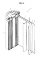
- a lithium battery 1 includes a cathode 3, an anode 2, and a separator 4.
- the cathode 3, the anode 2, and the separator 4 are wound or folded to be housed in a battery case 5.
- an organic electrolytic solution is injected into the battery case 5 and the resultant structure is sealed with a cap assembly 6, thereby completing manufacturing of the lithium battery 1.
- the battery case may have a cylindrical, rectangular, or thin-film form.
- the lithium battery 1 may be a large thin-film type battery.
- the lithium battery 1 may be a lithium ion battery.
- a battery assembly may be formed by interposing the separator between the cathode and the anode.
- a plurality of the battery assemblies may be stacked in a bi-cell structure, and then impregnated with an organic electrolytic solution, and the resultant structure is housed in a pouch and sealed, thereby completing manufacturing of a lithium ion polymer battery.
- the battery assemblies may be stacked on each other to form a battery pack, and the battery pack may be used in high-capacity and high-performance devices, such as a notebook computer, a smart phone, an electric vehicle (EV), etc.
- a notebook computer such as a notebook computer, a smart phone, an electric vehicle (EV), etc.
- EV electric vehicle
- the lithium battery Since the lithium battery has good charge and discharge efficiency characteristics and lifetime characteristics at high temperatures, the lithium battery is suitable for use in an EV.
- the lithium battery may be used in a hybrid vehicle such as a plug-in hybrid electric vehicle (PHEV).
- PHEV plug-in hybrid electric vehicle
- a mixture including LiNi 0.5 Mn 1.5 O 4 having an average diameter of 1000 nm, a carbon conductive agent (SUPER P ® Li, Timcal Corp.), and polyvinylidenefluoride (PVdF) at a weight ratio of 90:4:6 was mixed with N-methylpyrrolidone (NMP) in an agate mortar to prepare a slurry.
- NMP N-methylpyrrolidone
- the slurry was coated on an aluminum current collector by using a doctor blade to form a coating layer having a thickness of about 20 ⁇ m, and then the coating layer was dried at room temperature and then dried at a temperature of 120 °C under vacuum conditions, so as to prepare a cathode plate including a cathode active material layer.
- the cathode plate including the cathode active material layer was placed in a chamber and then F 2 gas was supplied to the chamber at a temperature of 25 °C and at a flow rate of 2000 sccm for 30 minutes, thereby fluorinating a surface of the cathode active material layer.
- a cathode plate was manufactured in the same manner as in Example 1, except that LiNiVO 4 was used instead of LiNi 0.5 Mn 1.5 O 4 .
- a cathode plate was manufactured in the same manner as in Example 1, except that LiCoPO 4 was used instead of LiNi 0.5 Mn 1.5 O 4 .
- a cathode plate was manufactured in the same manner as in Example 1, except that LiCoMnO 4 was used instead of LiNi 0.5 Mn 1.5 O 4 .
- a cathode plate was manufactured in the same manner as in Example 1, except that LiNiMn 3 O 8 was used instead of LiNi 0.5 Mn 1.5 O 4 .
- a cathode plate was manufactured in the same manner as in Example 1, except that carbon nanotubes were used instead of the conductive agent.
- a cathode plate was manufactured in the same manner as in Example 1, except that graphene was used instead of the conductive agent.
- a cathode plate was manufactured in the same manner as in Example 1, except that hard carbon was used instead of the conductive agent.
- a cathode plate was manufactured in the same manner as in Example 1, except that soft carbon was used instead of the conductive agent.
- a mixture including LiNi 0.5 Mn 1.5 O 4 having an average diameter of 1000 nm, a carbon conductive agent (SUPER P ® Li), and polyvinylidenefluoride (PVdF) at a weight ratio of 90:4:6 was mixed with N-methylpyrrolidone (NMP) in an agate mortar to prepare a slurry.
- NMP N-methylpyrrolidone
- the slurry was coated on an aluminum current collector by using a doctor blade to form a coating layer having a thickness of about 20 ⁇ m, and then the coating layer was dried at room temperature and then dried at a temperature of 120 °C under vacuum conditions, so as to prepare a cathode plate including a cathode active material layer.
- a mixture including LiNi 0.5 Mn 1.5 O 4 that had a fluorinated surface and had an average diameter of 1000 nm, a carbon conductive agent (SUPER P ® Li), and polyvinylidenefluoride (PVdF) at a weight ratio of 90:4:6 was mixed with N-methylpyrrolidone (NMP) in an agate mortar to prepare a slurry.
- NMP N-methylpyrrolidone
- the slurry was coated on an aluminum current collector by using a doctor blade to form a coating layer having a thickness of about 20 ⁇ m, and then the coating layer was dried at room temperature and then dried at a temperature of 120 °C under vacuum conditions, so as to prepare a cathode plate including a cathode active material layer.
- the LiNi 0.5 Mn 1.5 O 4 having a fluorinated surface was prepared by loading LiNi 0.5 Mn 15 O 4 powder into a chamber and supplying F 2 gas to the chamber at a temperature of 25 °C and at a flow rate of 2000 sccm for 30 minutes.
- a coin cell was manufactured using the cathode plate prepared according to Example 1, lithium metal as an opposite electrode, a separator formed of PE, and an electrolyte prepared by dissolving 1.0M LiPF 6 in a mixed solution including ethylene carbonate (EC) and dimethyl carbonate (DMC) in a volumetric ratio of 1:1.
- EC ethylene carbonate
- DMC dimethyl carbonate
- a coin cell was manufactured in the same manner as in Example 10, except that the cathode plate prepared according to Example 2 was used instead of the cathode plate prepared according to Example 1.
- a coin cell was manufactured in the same manner as in Example 10, except that the cathode plate prepared according to Example 3 was used instead of the cathode plate prepared according to Example 1.
- a coin cell was manufactured in the same manner as in Example 10, except that the cathode plate prepared according to Example 4 was used instead of the cathode plate prepared according to Example 1.
- a coin cell was manufactured in the same manner as in Example 10, except that the cathode plate prepared according to Example 5 was used instead of the cathode plate prepared according to Example 1.
- a coin cell was manufactured in the same manner as in Example 10, except that the cathode plate prepared according to Example 6 was used instead of the cathode plate prepared according to Example 1.
- a coin cell was manufactured in the same manner as in Example 10, except that the cathode plate prepared according to Example 7 was used instead of the cathode plate prepared according to Example 1.
- a coin cell was manufactured in the same manner as in Example 10, except that the cathode plate prepared according to Example 8 was used instead of the cathode plate prepared according to Example 1.
- a coin cell was manufactured in the same manner as in Example 10, except that the cathode plate prepared according to Example 9 was used instead of the cathode plate prepared according to Example 1.
- a coin cell was manufactured in the same manner as in Example 10, except that the cathode plate prepared according to Comparative Example 1 was used instead of the cathode plate prepared according to Example 1.
- a coin cell was manufactured in the same manner as in Example 10, except that the cathode plate prepared according to Comparative Example 2 was used instead of the cathode plate prepared according to Example 1.
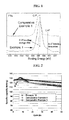
- FIG. 1 Surfaces of the cathode plates prepared according to Example 1 and Comparative Example 1 were analyzed by X-ray photoelectron spectroscopy (XPS), and the results are shown in FIG. 1 .
- XPS X-ray photoelectron spectroscopy
- FIG. 1 the binding energy of a peak corresponding to a C-F bonding of the cathode plate of Example 1 is lower than that of the cathode plate of Comparative Example 1.
- a peak corresponding to an Li-F bonding was formed. That is, it was confirmed that lithium and carbon atoms present at a surface of the cathode active material layer are bonded to fluorine atoms since the surface of the cathode active material layer of Example 1 is fluorinated.
- the C-F peak of Comparative Example 1 may be derived from the binder (PVdF) including fluorine atoms.
- the coin cells manufactured according to Example 10 and Comparative Examples 3 and 4 were charged and discharged fifty times with a constant current of 0.1 C in a voltage range of about 3.5 to about 4.9 V with respect to lithium metal at a temperature of 25 °C.
- Initial charge and discharge efficiency and discharge capacity in the first cycle are shown in Table 1.
- Initial charge and discharge efficiency in the first cycle is represented by Equation 1 below.
- lifetime characteristics in the 50 th cycle are shown in Table 2 below and in FIG. 2 .
- a capacity retention rate in the 50 th cycle is represented by Equation 2.
- Example 10 has higher initial charge and discharge efficiency than the coin cells manufactured according to Comparative Examples 3 and 4.
- Table 2 Capacity retention rate in the 50 th cycle [%] Example 10 95.2 Comparative Example 3 89.3 Comparative Example 4 92.3
- the coin cell manufactured according to Example 10 has better lifetime characteristics at room temperature than the coin cells manufactured according to Comparative Examples 3 and 4.
- the coin cell manufactured according to Example 10 has higher coulomb efficiency than the coin cells manufactured according to Comparative Examples 3 and 4 in each cycle.
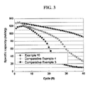
- Example 10 and Comparative Examples 3 and 4 were charged and discharged 40 times with a constant current of 1 C in a voltage range of about 3.5 to about 4.9 V with respect to lithium metal at a temperature of 60 °C. Lifetime characteristics in the 40 th cycle are shown in Table 3 below and in FIG. 3 . [Table 3] Capacity retention rate in the 40 th cycle [%] Example 5 70.9 Comparative Example 3 8.7 Comparative Example 4 20.5
- the coin cell manufactured according to Example 10 has better high-temperature lifetime characteristics than the coin cells manufactured according to Comparative Examples 3 and 4.
- the coin cell manufactured according to Example 10 has higher coulomb efficiency than the coin cells manufactured according to Comparative Examples 3 and 4 in each cycle.
Abstract
Description
- Aspects of the present disclosure relate to cathodes, methods of preparing the same, and lithium batteries including the cathodes.
- For use in various small and high-performing devices, lithium batteries are required to have a high energy density, small volume and light-weight characteristics. In addition, for use in electric vehicles, cycle characteristics of a lithium battery at room temperature and at high temperatures need to be regarded as critical factors.
- To realize a lithium battery satisfying the characteristics described above, various cathode active materials having a spinel structure are being reviewed. However, at a high-voltage of 4.6 V or greater, a side reaction occurs between cathode active materials having a spinel structure and an electrolyte. Due to the side reaction, initial charge and discharge efficiency and lifetime characteristics of a battery may be decreased.
- In addition, release of a transition metal from cathode active materials having a spinel structure at high temperatures may lead to low charge and discharge efficiency and poor high-temperature lifetime characteristics of a battery. Accordingly, there is a need to develop a method in which the side reaction and the release of a transition metal are suppressed.
- Cathodes are provided for suppressing a side reaction with an electrolyte at high voltages and release of a transition metal at high temperatures.
- Lithium batteries including the cathodes are also provided.
- Methods of preparing the cathodes are also provided.
- According to an aspect of the present invention, a cathode includes a current collector and a cathode active material layer disposed on the current collector; the cathode active material layer includes a lithium transition metal oxide having a spinel structure, a conductive agent, and a binder; and at least a portion of a surface of the cathode active material layer is fluorinated.
- According to another aspect of the present invention, a lithium battery includes the cathode.
- According to another aspect of the present invention, a method of forming a cathode includes forming a cathode active material layer on a current collector and fluorinating a surface of the cathode active material layer, where the cathode active material layer has a lithium transition metal oxide having a spinel structure, a conductive agent, and a binder.
- Additional aspects and/or advantages of the invention will be set forth in part in the description which follows and, in part, will be obvious from the description, or may be learned by practice of the invention.
- These and/or other aspects and advantages of the invention will become apparent and more readily appreciated from the following description of the embodiments, taken in conjunction with the accompanying drawings, of which:
-
FIG. 1 shows X-ray photoelectron spectroscopy (XPS) test results of surfaces of cathodes prepared according to Example 1 and Comparative Example 1; -
FIG. 2 shows room-temperature charge and discharge test results of lithium batteries prepared according to Example 10 and Comparative Examples 3 and 4; -
FIG. 3 shows high-temperature charge and discharge test results of lithium batteries manufactured according to Example 10 and Comparative Examples 3 and 4; and -
FIG. 4 is a schematic view of a lithium battery according to an embodiment of the present invention. - Reference will now be made in detail to the present embodiments of the present invention, examples of which are illustrated in the accompanying drawings, wherein like reference numerals refer to the like elements throughout. The embodiments are described below in order to explain the present invention by referring to the figures.
- Hereinafter, cathodes, methods of preparing the same, and lithium batteries including the cathodes according to exemplary embodiments of the present invention will be described in detail.
- A cathode according to an embodiment of the present invention includes a current collector and a cathode active material layer disposed on the current collector, in which the cathode active material layer has a lithium transition metal oxide having a spinel structure, a conductive agent, and a binder, and at least a portion of a surface of the cathode active material layer is fluorinated. That is, a coating layer including fluorine atoms may form either on a portion of the surface of the cathode active material layer or over the entire surface of the cathode active material layer.
- Either a portion of the surface or the entire surface of the cathode active material layer is bonded to fluorine atoms to form a protective layer formed of fluorine atoms. The protective layer may prevent a side reaction with an electrolyte. Also, the fluorinated protective layer may prevent release of a transition metal from the lithium transition metal oxide having a spinel structure.
- In the cathode, surfaces of the lithium transition metal oxide having a spinel structure and the conductive agent may be fluorinated. For example, lithium atoms, carbon atoms, and metallic atoms present at the surface of the cathode active material layer may be chemically bonded to fluorine atoms. Since the surface of the conductive agent is also fluorinated, a side reaction with an electrolyte may be further suppressed.
- In the cathode, the lithium transition metal oxide having a spinel structure may be represented by Formula 1:
<Formula 1> LixMn2-y-zNiyMzO4-nXn
where 0.25≤x≤1.1, 0.3≤y≤0.5, 0≤z≤0.15, and 0≤n:≤1; M includes one or more elements selected from the group consisting of gallium (Ga), zirconium (Zr), niobium (Nb), molybdenum (Mo), tungsten (W), barium (Ba), calcium (Ca), strontium (Sr), lanthanum (La), cerium (Ce), silver (Ag), tantalum (Ta), hafnium (Hf), ruthenium (Ru), bismuth (Bi), antimony (Sb), tin (Sn), and arsenic (As); and X includes one or more elements selected from the group consisting of fluorine (F), chlorine (Cl), bromine (Br), and iodine (I). For example, the lithium transition metal oxide having a spinel structure may be LiNi0.5Mn1.5O4. - Further, for another example, the lithium transition metal oxide having a spinel structure may be LiNiVO4, LiCoPO4, LiCoMnO4, LiNiM3O8, and the like.
- In the cathode, an average working potential of the lithium transition metal oxide having a spinel structure may be equal to or greater than 4.6 V. For example, the average working potential of the lithium transition metal oxide having a spinel structure may be in a range of about 4.6 to about 4.95 V.
- The term 'average working potential' used herein refers to a value given by dividing electric power during charging and discharging by current during charging and discharging when a battery is charged and discharged between upper and lower limits of a certain charge and discharge potential.
- In the cathode, an average diameter of the lithium transition metal oxide having a spinel structure may be in a range of about 20 nm to about 10 µm. Within the average diameter range, a lithium battery including the cathode may have good charge and discharge efficiency and lifetime characteristics.
- In the cathode, the conductive agent may include one or more elements selected from the group consisting of carbon black, graphite particles, natural graphite, artificial graphite, hard carbon, acetylene black, ketjen black, carbon fibers, carbon nanotubes, graphene, metal powder, metal fibers, metal tubes, and a conductive polymer. However, the conductive agent may not be limited thereto. For example, any one of various conductive agents that have a surface capable of being substituted with fluorine atoms may be used as the conductive agent.
- In the cathode, an average particle diameter of the conductive agent may be in a range of about 5 nm to about 500 nm. Within the average particle diameter range, the lithium battery may have good charge and discharge efficiency and lifetime characteristics.
- In the cathode, the surface of the cathode active material layer may be completely covered with fluorine atoms. That is, all portions of the surface of the cathode active material layer that may contact an electrolyte may be covered with fluorine atoms.
- In the cathode, the surface of the cathode may show a peak corresponding to Li-F bonding in X-ray photoelectron spectroscopy (XPS). The binding energy of a peak corresponding to the Li-F bonding may be 684eV ~ 685eV. Further, C-F bonding energy peak of the cathode of the present invention may shift to lower energy region by 0.2eV ~ 0.6eV in X-ray photoelectron spectroscopy (XPS) in comparison with the C-F peak of the cathode not fluorinated. In other words, C-F bonding energy peak of the cathode of the present invention may be 687.7eV ~ 687.3eV in X-ray photoelectron spectroscopy (XPS). Further, since the surface of the fluorinated cathode is already saturated with fluorine atoms, additional shift of the C-F peak to lower energy region cannot be obtained by any further fluorine treatment.
- A method of preparing a cathode according to an embodiment of the present invention includes forming a cathode active material layer on a current collector; and fluorinating a surface of the cathode active material layer, in which the cathode active material layer has a lithium transition metal oxide having a spinel structure, a conductive agent, and a binder.
- In the method, the fluorinating may be performed by contacting the surface of the cathode active material layer with either F2 gas or a mixed gas including F2 gas and an inert gas such as Ar gas.
- In the cathode, the fluorinating may be performed at a temperature of about 0 to about 100 °C. For example, the fluorinating may be performed at about 10 to about 40 °C. For example, the fluorinating may be performed at room temperature.
- If the fluorination temperature is higher than 100 °C, the binder may deteriorate, and thus the electrode binding force may be weakened. Also, the binding force between the cathode active material layer including the cathode active material, the conductive agent, and the binder and the current collector may be decreased, and thus the cathode active material layer and the conductive agent may separate from the current collector.
- In the method, the fluorinating may be performed by supplying a fluorine atom-containing gas at a flow rate of about 100 to about 10000 sccm (standard cubic centimeter per minutes) for about 30 to about 300 minutes. When the fluorine atom-containing gas is supplied for the gas supply time range described above, the lithium battery may have a good capacity retention rate and good lifetime characteristics.
- In the method, the lithium transition metal oxide having a spinel structure may be represented by Formula 1:
<Formula 1> LixMn2-y-zNiyMzO4-nXn
where 0.25≤x≤1.1, 0.3≤y≤0.5, 0≤z≤0.15, and 0≤n≤1; M includes one or more elements selected from the group consisting of Ga, Zr, Nb, Mo, W, Ba, Ca, Sr, La, Ce, Ag, Ta, Hf, Ru, Bi, Sb, Sn, and As; and X includes one or more elements selected from the group consisting of F, Cl, Br, and I. For example, the lithium transition metal oxide having a spinel structure may be LiNi0.5Mn1.5O4. - In the method, the conductive agent may include one or more elements selected from the group consisting of carbon black, graphite particles, natural graphite, artificial graphite, acetylene black, ketjen black, carbon fibers, carbon nanotubes, metal powder, metal fibers, metal tubes, and a conductive polymer. However, the conductive agent may not be limited thereto. For example, any one of various conductive agents that have a surface capable of being substituted with fluorine atoms may be used as the conductive agent.
- An example of the method of preparing the cathode will now be described in detail. First, a lithium transition metal oxide having a spinel structure, a conductive agent, a binder, and a solvent are mixed to prepare a cathode active material composition. The cathode active material composition may be directly coated on an aluminum current collector and dried to form a cathode plate including a cathode active material layer. Alternatively, the cathode active material composition may be cast on a separate support and separated from the support as a film and then the film is laminated on an aluminum current collector to form the cathode plate including the cathode active material layer.
- Then, F2 gas is supplied to the cathode plate at a flow rate of about 1000 to about 3000 sccm and at a temperature of about 0 to about 100 °C for about 30 to 300 minutes, thereby fluorinating a surface of the cathode active material layer. Due to the fluorination treatment, surfaces of the lithium transition metal oxide having a spinel structure and the conductive agent may be fluorinated.
- The conductive agent may be carbon black; graphite particles; natural graphite; artificial graphite; hard carbon; acetylene black; ketjen black; carbon fibers; carbon nanotubes; graphene; powder, fibers, or tubes of copper, nickel, aluminum, or silver; or a conductive polymer such as a polyphenylene derivative.
- The binder may be a vinylidene fluoride/hexafluoropropylene copolymer; polyvinylidenefluoride, polyacrylonitrile, polymethylmethacrylate , polytetrafluoroethylene, or a mixture thereof; or a styrene butadiene rubber-based polymer. The solvent may be N-methylpyrrolidone (NMP), acetone, or water. Amounts of the cathode active material, the conductive agent, the binder, and the solvent used herein may be used at the same levels as used in a traditional lithium battery.
- A lithium battery according to an embodiment of the present invention includes the cathode. An example of a method of manufacturing the lithium battery will now be described in detail.
- First, a cathode is prepared as described above. Then, as in the cathode plate preparation method, an anode active material, a conductive agent, a binder, and a solvent are mixed to prepare an anode active material composition, and the anode active material composition is directly coated on a copper current collector, thereby completing manufacturing of an anode plate. Alternatively, the anode active material composition is cast on a separate support and separated from the support as an anode active material film and then the anode active material film is laminated on a copper current collector, thereby completing manufacturing of an anode plate.
- The anode active material may not be particularly limited as long as it is conventionally used in the art. Examples of the anode active material are lithium metal, a metal that is alloyable with lithium, a transition metal oxide, a material that is used to dope or undope lithium, and a material that enables reversible intercalation and deintercalation of lithium ions.
- Examples of the transition metal oxide are tungsten oxide, molybdenum oxide, titanium oxide, lithium titanium oxide, vanadium oxide, and lithium vanadium oxide. Examples of the material that is used to dope or undope lithium are silicon (Si), SiOx (0<x<2), Si-Q alloy (Q may be an alkali metal, an alkali earth metal, a Group 13 element, a Group 14 element, a transition metal, a rare-earth element, or a combination thereof, and may not be Si), Sn, SnO2, and Sn-R (R may be an alkali metal, an alkali earth metal, a Group 13 element, a Group 14 element, a transition metal, a rare-earth element, or a combination thereof, and may not be Si), and at least one of these may be used in combination with SiO2 for use as the anode active material. The elements Q or R may be magnesium (Mg), calcium (Ca), strontium (Sr), barium (Ba), scandium (Sc), yttrium (Y), titanium (Ti), zirconium (Zr), hafnium (Hf), vanadium (V), niobium (Nb), tantalum (Ta), chromium (Cr), molybdenum (Mo), tungsten (W), rhenium (Re), iron (Fe), lead (Pb), ruthenium (Ru), osmium (Os), rhodium (Rh), iridium (Ir), palladium (Pd), platinum (Pt), copper (Cu), silver (Ag), gold (Au), zinc (Zn), cadmium (Cd), boron (B), aluminum (AI), gallium (Ga), tin (Sn), indium (In), titanium (Ti), germanium (Ge), phosphorus (P), arsenic (As), antimony (Sb), bismuth (Bi), sulfur (S), selenium (Se), tellurium (Te), or a combination thereof.
- The material that enables reversible intercalation and deintercalation of lithium ions may be any one of various carbonaceous anode active materials that are conventionally used in a lithium battery. Examples of the material that enables reversible intercalation and deintercalation of lithium ions are crystalline carbon, amorphous carbon, and a mixture thereof. Examples of crystalline carbon are plate, flake, spherical, or fiber-type natural graphite, and artificial graphite; and examples of amorphous carbon are soft carbon (low-temperature calcined carbon), hard carbon, mesophase pitch carbide, and calcined coke.
- The conductive agent, the binder, and the solvent of the anode active material composition may be the same as in a cathode. In another embodiment, each of the cathode active material composition and the anode active material composition may further include a plasticizer to form pores in the cathode or anode plate.
- Amounts of the anode active material, the conductive agent, the binder, and the solvent used herein may be used at the same levels as used in a traditional lithium battery. According to the purpose and structure of a particular lithium battery, one or more of the conductive agent, the binder, and the solvent may not be used.
- Then, a separator that is to be interposed between the cathode and the anode is prepared. The separator may be any one of various separators conventionally used in a lithium battery. The separator may have a low resistance to ion flow and a high electrolytic solution-retaining capability. Examples of the separator are glass fiber, polyester, polyethylene(PE), polypropylene, polytetrafluoroethylene (PTFE), and a combination thereof, and these separators may be in a non-woven or woven fabric form. For example, a separator suitable for a lithium ion battery may be a rollable separator formed of, for example, polyethylene or polypropylene, and a separator suitable for a lithium ion polymer battery may be a separator that has an excellent organic electrolytic solution-retaining capability. An example of a method of forming the separator will now be described in detail.
- A polymer resin, a filler, and a solvent are mixed to prepare a separator composition. The separator composition may be directly coated on an electrode and dried to form a separator. Alternatively, the separator composition may be cast on a support, dried, and then separated from the support as a separator film and then the separator film may be laminated on an electrode, thereby forming a separator.
- The polymer resin used in forming the separator may not be particularly limited and may be any one of various materials that are used as a binder of an electrode plate. Examples of the polymer are a vinylidenefluoride/hexafluoropropylene copolymer, polyvinylidenefluoride(PVDF), polyacrylonitrile, polymethylmethacrylate, and a mixture thereof.
- Then, an electrolyte is prepared. The electrolyte may be an organic electrolytic solution. In addition, the electrolyte may instead be solid. Examples of the solid electrolyte are boron oxide and lithium oxynitride, but are not limited thereto. The solid electrolyte may be any one of various solid electrolytes used in the art. The solid electrolyte may be formed on the anode by, for example, sputtering.
- For example, an organic electrolytic solution may be used as the electrolyte. The organic electrolytic solution may be prepared by dissolving a lithium salt in an organic solvent.
- The organic solvent may be any one of various organic solvents used in the art. Examples of the organic solvent are propylene carbonate, ethylene carbonate, fluoroethylene carbonate, butylene carbonate, dimethyl carbonate, diethyl carbonate, ethyl methyl carbonate, methyl propyl carbonate, ethylpropyl carbonate, methyl isopropy Icarbonate, dipropyl carbonate, dibutyl carbonate, benzonitrile, acetonitrile, tetrahydrofuran, 2-methyltetrahydrofuran, y-butyrolactone, 1,3-dioxolane, 4-methyl-1,3-dioxolane, N,N-dimethyl formamide, dimethylacetamide, dimethylsulfoxide, dioxane, 1,2-dimethoxyethane, sulfolane, dichloroethane, chlorobenzene, nitrobenzene, diethyleneglycol, dimethyl ether, and a mixture thereof.
- The lithium salt may be any one of various lithium salts used in the art. Examples of the lithium salt are LiPF6, LiBF4, LiSbF6, LiAsF6, LiClO4, LiCF3SO3, Li(CF3SO2)2N, LiC4F9SO3, LiAlO2, LiAICl4, LiN(CxF2x+1SO2)(CyF2y+1SO2)(each of x and y is a natural number), LiCl, Lil, and a mixture thereof.
- Referring to
FIG. 4 , alithium battery 1 includes acathode 3, ananode 2, and aseparator 4. Thecathode 3, theanode 2, and theseparator 4 are wound or folded to be housed in abattery case 5. Then, an organic electrolytic solution is injected into thebattery case 5 and the resultant structure is sealed with acap assembly 6, thereby completing manufacturing of thelithium battery 1. The battery case may have a cylindrical, rectangular, or thin-film form. For example, thelithium battery 1 may be a large thin-film type battery. In another embodiment, thelithium battery 1 may be a lithium ion battery. - Meanwhile, a battery assembly may be formed by interposing the separator between the cathode and the anode. A plurality of the battery assemblies may be stacked in a bi-cell structure, and then impregnated with an organic electrolytic solution, and the resultant structure is housed in a pouch and sealed, thereby completing manufacturing of a lithium ion polymer battery.
- In addition, the battery assemblies may be stacked on each other to form a battery pack, and the battery pack may be used in high-capacity and high-performance devices, such as a notebook computer, a smart phone, an electric vehicle (EV), etc.
- Since the lithium battery has good charge and discharge efficiency characteristics and lifetime characteristics at high temperatures, the lithium battery is suitable for use in an EV. For another example, the lithium battery may be used in a hybrid vehicle such as a plug-in hybrid electric vehicle (PHEV).
- One or more embodiments will now be described in further detail with reference to the following examples. These examples are for illustrative purpose only and are not intended to limit the scope of the one or more embodiments.
- A mixture including LiNi0.5Mn1.5O4 having an average diameter of 1000 nm, a carbon conductive agent (SUPER P® Li, Timcal Corp.), and polyvinylidenefluoride (PVdF) at a weight ratio of 90:4:6 was mixed with N-methylpyrrolidone (NMP) in an agate mortar to prepare a slurry. The slurry was coated on an aluminum current collector by using a doctor blade to form a coating layer having a thickness of about 20 µm, and then the coating layer was dried at room temperature and then dried at a temperature of 120 °C under vacuum conditions, so as to prepare a cathode plate including a cathode active material layer.
- The cathode plate including the cathode active material layer was placed in a chamber and then F2 gas was supplied to the chamber at a temperature of 25 °C and at a flow rate of 2000 sccm for 30 minutes, thereby fluorinating a surface of the cathode active material layer.
- A cathode plate was manufactured in the same manner as in Example 1, except that LiNiVO4 was used instead of LiNi0.5Mn1.5O4.
- A cathode plate was manufactured in the same manner as in Example 1, except that LiCoPO4 was used instead of LiNi0.5Mn1.5O4.
- A cathode plate was manufactured in the same manner as in Example 1, except that LiCoMnO4 was used instead of LiNi0.5Mn1.5O4.
- A cathode plate was manufactured in the same manner as in Example 1, except that LiNiMn3O8 was used instead of LiNi0.5Mn1.5O4.
- A cathode plate was manufactured in the same manner as in Example 1, except that carbon nanotubes were used instead of the conductive agent.
- A cathode plate was manufactured in the same manner as in Example 1, except that graphene was used instead of the conductive agent.
- A cathode plate was manufactured in the same manner as in Example 1, except that hard carbon was used instead of the conductive agent.
- A cathode plate was manufactured in the same manner as in Example 1, except that soft carbon was used instead of the conductive agent.
- A mixture including LiNi0.5Mn1.5O4 having an average diameter of 1000 nm, a carbon conductive agent (SUPER P® Li), and polyvinylidenefluoride (PVdF) at a weight ratio of 90:4:6 was mixed with N-methylpyrrolidone (NMP) in an agate mortar to prepare a slurry. The slurry was coated on an aluminum current collector by using a doctor blade to form a coating layer having a thickness of about 20 µm, and then the coating layer was dried at room temperature and then dried at a temperature of 120 °C under vacuum conditions, so as to prepare a cathode plate including a cathode active material layer.
- A mixture including LiNi0.5Mn1.5O4 that had a fluorinated surface and had an average diameter of 1000 nm, a carbon conductive agent (SUPER P® Li), and polyvinylidenefluoride (PVdF) at a weight ratio of 90:4:6 was mixed with N-methylpyrrolidone (NMP) in an agate mortar to prepare a slurry. The slurry was coated on an aluminum current collector by using a doctor blade to form a coating layer having a thickness of about 20 µm, and then the coating layer was dried at room temperature and then dried at a temperature of 120 °C under vacuum conditions, so as to prepare a cathode plate including a cathode active material layer.
- The LiNi0.5Mn1.5O4 having a fluorinated surface was prepared by loading LiNi0.5Mn15O4 powder into a chamber and supplying F2 gas to the chamber at a temperature of 25 °C and at a flow rate of 2000 sccm for 30 minutes.
- A coin cell was manufactured using the cathode plate prepared according to Example 1, lithium metal as an opposite electrode, a separator formed of PE, and an electrolyte prepared by dissolving 1.0M LiPF6 in a mixed solution including ethylene carbonate (EC) and dimethyl carbonate (DMC) in a volumetric ratio of 1:1.
- A coin cell was manufactured in the same manner as in Example 10, except that the cathode plate prepared according to Example 2 was used instead of the cathode plate prepared according to Example 1.
- A coin cell was manufactured in the same manner as in Example 10, except that the cathode plate prepared according to Example 3 was used instead of the cathode plate prepared according to Example 1.
- A coin cell was manufactured in the same manner as in Example 10, except that the cathode plate prepared according to Example 4 was used instead of the cathode plate prepared according to Example 1.
- A coin cell was manufactured in the same manner as in Example 10, except that the cathode plate prepared according to Example 5 was used instead of the cathode plate prepared according to Example 1.
- A coin cell was manufactured in the same manner as in Example 10, except that the cathode plate prepared according to Example 6 was used instead of the cathode plate prepared according to Example 1.
- A coin cell was manufactured in the same manner as in Example 10, except that the cathode plate prepared according to Example 7 was used instead of the cathode plate prepared according to Example 1.
- A coin cell was manufactured in the same manner as in Example 10, except that the cathode plate prepared according to Example 8 was used instead of the cathode plate prepared according to Example 1.
- A coin cell was manufactured in the same manner as in Example 10, except that the cathode plate prepared according to Example 9 was used instead of the cathode plate prepared according to Example 1.
- A coin cell was manufactured in the same manner as in Example 10, except that the cathode plate prepared according to Comparative Example 1 was used instead of the cathode plate prepared according to Example 1.
- A coin cell was manufactured in the same manner as in Example 10, except that the cathode plate prepared according to Comparative Example 2 was used instead of the cathode plate prepared according to Example 1.
- Surfaces of the cathode plates prepared according to Example 1 and Comparative Example 1 were analyzed by X-ray photoelectron spectroscopy (XPS), and the results are shown in
FIG. 1 . As shown inFIG. 1 , the binding energy of a peak corresponding to a C-F bonding of the cathode plate of Example 1 is lower than that of the cathode plate of Comparative Example 1. In addition, regarding the cathode plate of Example 1, a peak corresponding to an Li-F bonding was formed. That is, it was confirmed that lithium and carbon atoms present at a surface of the cathode active material layer are bonded to fluorine atoms since the surface of the cathode active material layer of Example 1 is fluorinated. The C-F peak of Comparative Example 1 may be derived from the binder (PVdF) including fluorine atoms. - The coin cells manufactured according to Example 10 and Comparative Examples 3 and 4 were charged and discharged fifty times with a constant current of 0.1 C in a voltage range of about 3.5 to about 4.9 V with respect to lithium metal at a temperature of 25 °C. Initial charge and discharge efficiency and discharge capacity in the first cycle are shown in Table 1. Initial charge and discharge efficiency in the first cycle is represented by
Equation 1 below. In addition, lifetime characteristics in the 50th cycle are shown in Table 2 below and inFIG. 2 . A capacity retention rate in the 50th cycle is represented byEquation 2.

[Table 1] Initial charge and discharge efficiency [%] Charge capacity in the 50th cycle [mAh/g] Example 10 93.7 126 Comparative Example 3 82.4 126 Comparative Example 4 84.2 126 - As shown in Table 1, the coin cell manufactured according to Example 10 has higher initial charge and discharge efficiency than the coin cells manufactured according to Comparative Examples 3 and 4.
[Table 2] Capacity retention rate in the 50th cycle [%] Example 10 95.2 Comparative Example 3 89.3 Comparative Example 4 92.3 - As shown in Table 2 above, the coin cell manufactured according to Example 10 has better lifetime characteristics at room temperature than the coin cells manufactured according to Comparative Examples 3 and 4. In addition, although not illustrated in the drawings, the coin cell manufactured according to Example 10 has higher coulomb efficiency than the coin cells manufactured according to Comparative Examples 3 and 4 in each cycle.
- The coin cells manufactured according to Example 10 and Comparative Examples 3 and 4 were charged and discharged 40 times with a constant current of 1 C in a voltage range of about 3.5 to about 4.9 V with respect to lithium metal at a temperature of 60 °C. Lifetime characteristics in the 40th cycle are shown in Table 3 below and in
FIG. 3 .[Table 3] Capacity retention rate in the 40th cycle [%] Example 5 70.9 Comparative Example 3 8.7 Comparative Example 4 20.5 - As shown in Table 3 and in
FIG. 3 , the coin cell manufactured according to Example 10 has better high-temperature lifetime characteristics than the coin cells manufactured according to Comparative Examples 3 and 4. In addition, although not illustrated in the drawings, the coin cell manufactured according to Example 10 has higher coulomb efficiency than the coin cells manufactured according to Comparative Examples 3 and 4 in each cycle. - As described above, according to the one or more of the above embodiments of the present invention, by fluorinating a surface of a cathode, efficiency and lifetime characteristics of a lithium battery including the cathode may be improved.
- Although a few embodiments of the present invention have been shown and described, it would be appreciated by those skilled in the art that changes may be made in these embodiments without departing from the principles of the invention.
Claims (15)
- A cathode (3) comprising: a current collector; and
a cathode active material layer disposed on the current collector,
wherein the cathode active material layer comprises a lithium transition metal oxide having a spinel structure, a conductive agent, and a binder, and
at least a portion of a surface of the cathode active material layer is fluorinated. - The cathode of claim 1, wherein surfaces of the lithium transition metal oxide having the spinel structure and the conductive agent are fluorinated.
- The cathode of claim 1 or 2, wherein the lithium transition metal oxide having the spinel structure is represented by Formula 1 below:
<Formula 1> LixMn2-y-zNiyMzO4-nXn
wherein 0.25≤x≤1.1, 0.3≤y≤0.5, 0≤z≤0.15, and 0≤n≤1,
M comprises one or more elements selected from the group consisting of gallium (Ga), zirconium (Zr), niobium (Nb), molybdenum (Mo), tungsten (W), barium (Ba), calcium (Ca), strontium (Sr), lanthanum (La), cerium (Ce), silver (Ag), tantalum (Ta), hafnium (Hf), ruthenium (Ru), bismuth (Bi), antimony (Sb), tin (Sn), and arsenic (As),; and
X comprises one or more elements selected from the group consisting of fluorine (F), chlorine (Cl), bromine (Br), and iodine (I),
and optionally wherein the lithium transition metal oxide having a spinel structure is LiNiVO4, LiCoPO4, LiCoMnO4, or LiNiM3O8,
and further optionally wherein the lithium transition metal oxide having the spinel structure is LiNi0.5Mn1.5O4. - The cathode of any preceding claim, wherein an average working potential of the lithium transition metal oxide having the spinel structure is equal to or greater than 4.6 V.
- The cathode of any preceding claim, wherein an average particle size of the lithium transition metal oxide having the spinel structure is in a range of 20 nm to 10 µm.
- The cathode of any preceding claim, wherein the conductive agent comprises at least one material selected from the group consisting of carbon black, graphite particles, natural graphite, artificial graphite, hard carbon, acetylene black, ketjen black, carbon fibers, carbon nanotubes, graphene, metal powder, metal fibers, metal tubes, and a conductive polymer.
- The cathode of any preceding claim, wherein an average particle size of the conductive agent is in a range of 5 nm to 500 nm.
- The cathode of any preceding claim, wherein the surface of the cathode active material layer is completely coated with fluorine atoms.
- A lithium battery comprising the cathode of any preceding claim.
- A lithium battery according to claim 9 comprising:the cathode (3) according to any of claims 1 to 8 incorporating the current collector and the cathode active material layer disposed on the current collector;an anode (2);a separator (4) separating the cathode and the anode;a battery case (5) incorporating the cathode, anode, and separator;an organic electrolyte ; anda cap assembly (6), wherein:the cathode (3), anode (2) and separator (4) are wound or folded and housed in the battery case (5), andthe cathode (3), anode (2), separator (4) and organic electrolyte are sealed in the battery case (5) with the cap assembly (6).
- A method of forming a cathode (3), the method comprising:forming a cathode active material layer on a current collector; andfluorinating a surface of the cathode active material layer,wherein the cathode active material layer has a lithium transition metal oxide having a spinel structure, a conductive agent, and a binder.
- The method of claim 11, wherein the fluorinating is performed by contacting the surface of the cathode active material layer with a gas comprising fluorine atoms.
- The method of claim 12, wherein the fluorinating is performed at a temperature of 0 to 100 °C,
optionally at a temperature of 10 to 40 °C,
and further optionally wherein the fluorinating is performed at room temperature. - The method of claim 11, 13 or 13, wherein the fluorinating is performed by contacting the surface of the cathode active material layer with a mixed gas comprising fluorine atoms and an inert gas,
and optionally wherein the inert gas is argon. - The method of claim 10, wherein the fluorinating is performed at a gas flow rate of about 100 to about 10,000 standard cubic centimeters per minute for 30 to 300 minutes.
Applications Claiming Priority (1)
| Application Number | Priority Date | Filing Date | Title |
|---|---|---|---|
| KR1020100095965A KR101228115B1 (en) | 2010-10-01 | 2010-10-01 | Cathode, preparation method thereof, and lithium battery containing the same |
Publications (2)
| Publication Number | Publication Date |
|---|---|
| EP2437337A1 true EP2437337A1 (en) | 2012-04-04 |
| EP2437337B1 EP2437337B1 (en) | 2013-08-21 |
Family
ID=44763941
Family Applications (1)
| Application Number | Title | Priority Date | Filing Date |
|---|---|---|---|
| EP11183689.6A Active EP2437337B1 (en) | 2010-10-01 | 2011-10-03 | Cathode, method of preparing the same, and lithium battery including the cathode |
Country Status (3)
| Country | Link |
|---|---|
| US (1) | US9070931B2 (en) |
| EP (1) | EP2437337B1 (en) |
| KR (1) | KR101228115B1 (en) |
Cited By (4)
| Publication number | Priority date | Publication date | Assignee | Title |
|---|---|---|---|---|
| JP2014082050A (en) * | 2012-10-15 | 2014-05-08 | Nissan Motor Co Ltd | Positive electrode for battery |
| CN104185915A (en) * | 2012-04-18 | 2014-12-03 | 株式会社Lg化学 | Electrode for secondary battery, and secondary battery comprising same |
| EP2863457A1 (en) * | 2013-05-23 | 2015-04-22 | LG Chem, Ltd. | Lithium secondary battery comprising multilayered active material layer |
| CN109148887A (en) * | 2018-08-30 | 2019-01-04 | 上海力信能源科技有限责任公司 | A kind of production method of graphene-carbon nano-fiber conductive agent |
Families Citing this family (10)
| Publication number | Priority date | Publication date | Assignee | Title |
|---|---|---|---|---|
| US20140332731A1 (en) * | 2012-04-02 | 2014-11-13 | CNano Technology Limited | Electrode Composition for Battery |
| US9780358B2 (en) * | 2012-05-04 | 2017-10-03 | Zenlabs Energy, Inc. | Battery designs with high capacity anode materials and cathode materials |
| US10553871B2 (en) | 2012-05-04 | 2020-02-04 | Zenlabs Energy, Inc. | Battery cell engineering and design to reach high energy |
| CN103198935B (en) * | 2013-04-18 | 2016-01-20 | 山东大学 | The preparation method of a kind of graphene film modified spinelle type LiMn2O4 or α type manganese dioxide electrode |
| JP2016522552A (en) * | 2013-07-31 | 2016-07-28 | エルジー・ケム・リミテッド | Negative electrode active material for secondary batteries with improved life characteristics |
| US11476494B2 (en) | 2013-08-16 | 2022-10-18 | Zenlabs Energy, Inc. | Lithium ion batteries with high capacity anode active material and good cycling for consumer electronics |
| US9786914B2 (en) * | 2013-12-04 | 2017-10-10 | Mitsui Mining & Smelting Co., Ltd. | Spinel-type lithium cobalt manganese-containing complex oxide |
| US9768421B2 (en) | 2014-10-10 | 2017-09-19 | Samsung Electronics Co., Ltd. | Flexible electrode assembly and electrochemical device having the electrode assembly |
| US11094925B2 (en) | 2017-12-22 | 2021-08-17 | Zenlabs Energy, Inc. | Electrodes with silicon oxide active materials for lithium ion cells achieving high capacity, high energy density and long cycle life performance |
| US11605851B1 (en) * | 2021-09-21 | 2023-03-14 | Knoetik Solutions, Inc. | Systems, methods and apparatus for improving rechargeable energy storage devices and integrated circuits |
Citations (4)
| Publication number | Priority date | Publication date | Assignee | Title |
|---|---|---|---|---|
| JPH08213014A (en) * | 1995-02-06 | 1996-08-20 | Sony Corp | Nonaqueous electrolyte secondary battery |
| US20080090149A1 (en) * | 2006-10-11 | 2008-04-17 | Matsushita Electric Industrial Co., Ltd. | Non-aqueous electrolyte battery |
| JP2009110952A (en) * | 2007-10-11 | 2009-05-21 | Univ Of Fukui | Cathode material for nonaqueous electrolyte secondary battery |
| US20090286157A1 (en) * | 2008-05-16 | 2009-11-19 | Zonghai Chen | Surface modification agents for lithium batteries |
Family Cites Families (6)
| Publication number | Priority date | Publication date | Assignee | Title |
|---|---|---|---|---|
| JPH04193481A (en) | 1990-11-26 | 1992-07-13 | Sintokogio Ltd | Grinding and cleaning equipment |
| US6818352B2 (en) * | 1999-03-07 | 2004-11-16 | Teijin Limited | Lithium secondary cell, separator, cell pack, and charging method |
| JP4193481B2 (en) * | 2002-12-10 | 2008-12-10 | ソニー株式会社 | Positive electrode active material, method for producing the same, and nonaqueous electrolyte secondary battery |
| JP2005011688A (en) | 2003-06-19 | 2005-01-13 | Toyo Tanso Kk | Nonaqueous electrolyte secondary battery positive electrode activator and manufacturing method of the same |
| JP5208353B2 (en) | 2005-03-31 | 2013-06-12 | 東洋炭素株式会社 | Positive electrode active material and manufacturing method thereof |
| KR100874539B1 (en) * | 2007-05-31 | 2008-12-16 | 엘에스엠트론 주식회사 | Spinel-type composite solid oxide, a manufacturing method thereof, and a lithium secondary battery comprising the same as an anode |
-
2010
- 2010-10-01 KR KR1020100095965A patent/KR101228115B1/en active IP Right Grant
-
2011
- 2011-08-03 US US13/197,107 patent/US9070931B2/en active Active
- 2011-10-03 EP EP11183689.6A patent/EP2437337B1/en active Active
Patent Citations (4)
| Publication number | Priority date | Publication date | Assignee | Title |
|---|---|---|---|---|
| JPH08213014A (en) * | 1995-02-06 | 1996-08-20 | Sony Corp | Nonaqueous electrolyte secondary battery |
| US20080090149A1 (en) * | 2006-10-11 | 2008-04-17 | Matsushita Electric Industrial Co., Ltd. | Non-aqueous electrolyte battery |
| JP2009110952A (en) * | 2007-10-11 | 2009-05-21 | Univ Of Fukui | Cathode material for nonaqueous electrolyte secondary battery |
| US20090286157A1 (en) * | 2008-05-16 | 2009-11-19 | Zonghai Chen | Surface modification agents for lithium batteries |
Non-Patent Citations (2)
| Title |
|---|
| CHOWDARI, B. V. R.; WANG, WENJI: "Solid State Ionics: Materials and Devices, [Proceedings of the Asian Conference], 7th, Fuzhou, China, Oct. 29-Nov. 4", 4 November 2000, WORLD SCIENTIFIC PUBLISHING CO. PTE. LTD., SINGAPORE, Singapore, article WU, CHUAN; WU, FENG; HUANG, XUEJIE: "Modification of spinel LiMn2O4 using an electrochemical method", pages: 267 - 270, XP002665970 * |
| FOREST T. QUINLAN ET AL: "Surface Characterization of the Spinel Li x Mn 2 O 4 Cathode before and after Storage at Elevated Temperatures", CHEMISTRY OF MATERIALS, vol. 13, no. 11, 1 November 2001 (2001-11-01), pages 4207 - 4212, XP055015003, ISSN: 0897-4756, DOI: 10.1021/cm010335v * |
Cited By (9)
| Publication number | Priority date | Publication date | Assignee | Title |
|---|---|---|---|---|
| CN104185915A (en) * | 2012-04-18 | 2014-12-03 | 株式会社Lg化学 | Electrode for secondary battery, and secondary battery comprising same |
| EP2811552A4 (en) * | 2012-04-18 | 2015-09-02 | Lg Chemical Ltd | Electrode for secondary battery, and secondary battery comprising same |
| US9508993B2 (en) | 2012-04-18 | 2016-11-29 | Lg Chem, Ltd. | Electrode for secondary battery and secondary battery including the same |
| US10153480B2 (en) | 2012-04-18 | 2018-12-11 | Lg Chem, Ltd. | Electrode for secondary battery and secondary battery including the same |
| JP2014082050A (en) * | 2012-10-15 | 2014-05-08 | Nissan Motor Co Ltd | Positive electrode for battery |
| EP2863457A1 (en) * | 2013-05-23 | 2015-04-22 | LG Chem, Ltd. | Lithium secondary battery comprising multilayered active material layer |
| EP2863457A4 (en) * | 2013-05-23 | 2015-04-22 | Lg Chemical Ltd | Lithium secondary battery comprising multilayered active material layer |
| US9318738B2 (en) | 2013-05-23 | 2016-04-19 | Lg Chem, Ltd. | Lithium secondary battery including multi-layered active material layers |
| CN109148887A (en) * | 2018-08-30 | 2019-01-04 | 上海力信能源科技有限责任公司 | A kind of production method of graphene-carbon nano-fiber conductive agent |
Also Published As
| Publication number | Publication date |
|---|---|
| KR20120034414A (en) | 2012-04-12 |
| US9070931B2 (en) | 2015-06-30 |
| KR101228115B1 (en) | 2013-02-01 |
| US20120082877A1 (en) | 2012-04-05 |
| EP2437337B1 (en) | 2013-08-21 |
Similar Documents
| Publication | Publication Date | Title |
|---|---|---|
| EP2437337B1 (en) | Cathode, method of preparing the same, and lithium battery including the cathode | |
| US8841026B2 (en) | Cathode, method of preparing the same, and lithium battery including the cathode | |
| CN103094538B (en) | Negative active core-shell material and preparation method thereof, negative electrode and lithium battery | |
| KR101785262B1 (en) | Positive electrode active material, preparing method thereof, positive electrode including the same, and lithium secondary battery employing the positive electrode | |
| EP2538473B1 (en) | Composite cathode active material, cathode and lithium battery including the composite cathode active material, and method of preparing the composite cathode active material | |
| US9123952B2 (en) | Negative electrode active material, method of preparing the same, negative electrode and lithium secondary battery employing the electrode including the negative electrode active material | |
| US8932481B2 (en) | Cathode active material, method of preparing the same, and cathode and lithium battery including the cathode active material | |
| US9742005B2 (en) | Composite cathode active material, cathode and lithium battery containing the composite cathode active material | |
| CN108075115B (en) | Composite positive active material, positive electrode and lithium battery including the same, and method of preparing composite positive active material | |
| US20140212694A1 (en) | Composite anode active material, anode including the same, lithium battery including the anode, and method of preparing the composite anode active material | |
| US20140072874A1 (en) | Composite cathode active material, cathode and lithium battery including the composite cathode active material, and method of preparing the composite cathode active material | |
| US20240021792A1 (en) | Anode active material for lithium secondary battery and lithium secondary battery comprising anode including the anode active material | |
| US10290862B2 (en) | Composite cathode active material, cathode and lithium battery including the composite cathode active material, and method of preparing the composite cathode active material | |
| US10930921B2 (en) | Negative active material having a silicon alloy core and a shell including a metal oxide, negative electrode and lithium secondary battery including the same, and method of preparing the negative active material | |
| KR20170024490A (en) | Composite positive active material, positive electrode including the same, and lithium battery including the positive electrode | |
| US20130011731A1 (en) | Cathode slurry composition, cathode prepared from the same, and lithium battery comprising the cathode | |
| KR20150095451A (en) | Lithium battery | |
| JP5492380B2 (en) | Composite cathode active material, method for producing the same, cathode and lithium battery employing the same | |
| KR102344365B1 (en) | Lithium battery | |
| KR20080070492A (en) | Composite anode active material, method of preparing the same, and anode and lithium battery containing the material | |
| KR102344364B1 (en) | Lithium battery | |
| KR102523095B1 (en) | A cathode active material, method of preparing the same, lithium secondary battery comprising the cathode active material | |
| EP4037009A2 (en) | Positive electrode, lithium battery including positive electrode, and method of manufacturing positive electrode | |
| KR20180107620A (en) | Lithium secondary battery |
Legal Events
| Date | Code | Title | Description |
|---|---|---|---|
| PUAI | Public reference made under article 153(3) epc to a published international application that has entered the european phase |
Free format text: ORIGINAL CODE: 0009012 |
|
| AK | Designated contracting states |
Kind code of ref document: A1 Designated state(s): AL AT BE BG CH CY CZ DE DK EE ES FI FR GB GR HR HU IE IS IT LI LT LU LV MC MK MT NL NO PL PT RO RS SE SI SK SM TR |
|
| AX | Request for extension of the european patent |
Extension state: BA ME |
|
| RAP1 | Party data changed (applicant data changed or rights of an application transferred) |
Owner name: INDUSTRY-UNIVERSITY COOPERATION FOUNDATION HANYANG Owner name: SAMSUNG ELECTRONICS CO., LTD. |
|
| 17P | Request for examination filed |
Effective date: 20121004 |
|
| GRAP | Despatch of communication of intention to grant a patent |
Free format text: ORIGINAL CODE: EPIDOSNIGR1 |
|
| RIC1 | Information provided on ipc code assigned before grant |
Ipc: H01M 4/62 20060101AFI20130207BHEP Ipc: H01M 4/505 20100101ALI20130207BHEP Ipc: H01M 4/36 20060101ALI20130207BHEP Ipc: H01M 4/1315 20100101ALI20130207BHEP Ipc: H01M 4/13915 20100101ALI20130207BHEP |
|
| GRAS | Grant fee paid |
Free format text: ORIGINAL CODE: EPIDOSNIGR3 |
|
| GRAA | (expected) grant |
Free format text: ORIGINAL CODE: 0009210 |
|
| AK | Designated contracting states |
Kind code of ref document: B1 Designated state(s): AL AT BE BG CH CY CZ DE DK EE ES FI FR GB GR HR HU IE IS IT LI LT LU LV MC MK MT NL NO PL PT RO RS SE SI SK SM TR |
|
| REG | Reference to a national code |
Ref country code: GB Ref legal event code: FG4D |
|
| REG | Reference to a national code |
Ref country code: CH Ref legal event code: EP |
|
| REG | Reference to a national code |
Ref country code: AT Ref legal event code: REF Ref document number: 628555 Country of ref document: AT Kind code of ref document: T Effective date: 20130915 |
|
| REG | Reference to a national code |
Ref country code: IE Ref legal event code: FG4D |
|
| REG | Reference to a national code |
Ref country code: DE Ref legal event code: R096 Ref document number: 602011002685 Country of ref document: DE Effective date: 20131017 |
|
| REG | Reference to a national code |
Ref country code: AT Ref legal event code: MK05 Ref document number: 628555 Country of ref document: AT Kind code of ref document: T Effective date: 20130821 Ref country code: NL Ref legal event code: VDEP Effective date: 20130821 |
|
| REG | Reference to a national code |
Ref country code: LT Ref legal event code: MG4D |
|
| PG25 | Lapsed in a contracting state [announced via postgrant information from national office to epo] |
Ref country code: AT Free format text: LAPSE BECAUSE OF FAILURE TO SUBMIT A TRANSLATION OF THE DESCRIPTION OR TO PAY THE FEE WITHIN THE PRESCRIBED TIME-LIMIT Effective date: 20130821 Ref country code: NO Free format text: LAPSE BECAUSE OF FAILURE TO SUBMIT A TRANSLATION OF THE DESCRIPTION OR TO PAY THE FEE WITHIN THE PRESCRIBED TIME-LIMIT Effective date: 20131121 Ref country code: IS Free format text: LAPSE BECAUSE OF FAILURE TO SUBMIT A TRANSLATION OF THE DESCRIPTION OR TO PAY THE FEE WITHIN THE PRESCRIBED TIME-LIMIT Effective date: 20131221 Ref country code: PT Free format text: LAPSE BECAUSE OF FAILURE TO SUBMIT A TRANSLATION OF THE DESCRIPTION OR TO PAY THE FEE WITHIN THE PRESCRIBED TIME-LIMIT Effective date: 20131223 Ref country code: CY Free format text: LAPSE BECAUSE OF FAILURE TO SUBMIT A TRANSLATION OF THE DESCRIPTION OR TO PAY THE FEE WITHIN THE PRESCRIBED TIME-LIMIT Effective date: 20130821 Ref country code: HR Free format text: LAPSE BECAUSE OF FAILURE TO SUBMIT A TRANSLATION OF THE DESCRIPTION OR TO PAY THE FEE WITHIN THE PRESCRIBED TIME-LIMIT Effective date: 20130821 Ref country code: SE Free format text: LAPSE BECAUSE OF FAILURE TO SUBMIT A TRANSLATION OF THE DESCRIPTION OR TO PAY THE FEE WITHIN THE PRESCRIBED TIME-LIMIT Effective date: 20130821 Ref country code: LT Free format text: LAPSE BECAUSE OF FAILURE TO SUBMIT A TRANSLATION OF THE DESCRIPTION OR TO PAY THE FEE WITHIN THE PRESCRIBED TIME-LIMIT Effective date: 20130821 |
|
| PG25 | Lapsed in a contracting state [announced via postgrant information from national office to epo] |
Ref country code: LV Free format text: LAPSE BECAUSE OF FAILURE TO SUBMIT A TRANSLATION OF THE DESCRIPTION OR TO PAY THE FEE WITHIN THE PRESCRIBED TIME-LIMIT Effective date: 20130821 Ref country code: PL Free format text: LAPSE BECAUSE OF FAILURE TO SUBMIT A TRANSLATION OF THE DESCRIPTION OR TO PAY THE FEE WITHIN THE PRESCRIBED TIME-LIMIT Effective date: 20130821 Ref country code: FI Free format text: LAPSE BECAUSE OF FAILURE TO SUBMIT A TRANSLATION OF THE DESCRIPTION OR TO PAY THE FEE WITHIN THE PRESCRIBED TIME-LIMIT Effective date: 20130821 Ref country code: SI Free format text: LAPSE BECAUSE OF FAILURE TO SUBMIT A TRANSLATION OF THE DESCRIPTION OR TO PAY THE FEE WITHIN THE PRESCRIBED TIME-LIMIT Effective date: 20130821 Ref country code: BE Free format text: LAPSE BECAUSE OF FAILURE TO SUBMIT A TRANSLATION OF THE DESCRIPTION OR TO PAY THE FEE WITHIN THE PRESCRIBED TIME-LIMIT Effective date: 20130821 Ref country code: GR Free format text: LAPSE BECAUSE OF FAILURE TO SUBMIT A TRANSLATION OF THE DESCRIPTION OR TO PAY THE FEE WITHIN THE PRESCRIBED TIME-LIMIT Effective date: 20131122 |
|
| PG25 | Lapsed in a contracting state [announced via postgrant information from national office to epo] |
Ref country code: EE Free format text: LAPSE BECAUSE OF FAILURE TO SUBMIT A TRANSLATION OF THE DESCRIPTION OR TO PAY THE FEE WITHIN THE PRESCRIBED TIME-LIMIT Effective date: 20130821 Ref country code: DK Free format text: LAPSE BECAUSE OF FAILURE TO SUBMIT A TRANSLATION OF THE DESCRIPTION OR TO PAY THE FEE WITHIN THE PRESCRIBED TIME-LIMIT Effective date: 20130821 Ref country code: SK Free format text: LAPSE BECAUSE OF FAILURE TO SUBMIT A TRANSLATION OF THE DESCRIPTION OR TO PAY THE FEE WITHIN THE PRESCRIBED TIME-LIMIT Effective date: 20130821 Ref country code: RO Free format text: LAPSE BECAUSE OF FAILURE TO SUBMIT A TRANSLATION OF THE DESCRIPTION OR TO PAY THE FEE WITHIN THE PRESCRIBED TIME-LIMIT Effective date: 20130821 Ref country code: NL Free format text: LAPSE BECAUSE OF FAILURE TO SUBMIT A TRANSLATION OF THE DESCRIPTION OR TO PAY THE FEE WITHIN THE PRESCRIBED TIME-LIMIT Effective date: 20130821 Ref country code: CZ Free format text: LAPSE BECAUSE OF FAILURE TO SUBMIT A TRANSLATION OF THE DESCRIPTION OR TO PAY THE FEE WITHIN THE PRESCRIBED TIME-LIMIT Effective date: 20130821 |
|
| PG25 | Lapsed in a contracting state [announced via postgrant information from national office to epo] |
Ref country code: ES Free format text: LAPSE BECAUSE OF FAILURE TO SUBMIT A TRANSLATION OF THE DESCRIPTION OR TO PAY THE FEE WITHIN THE PRESCRIBED TIME-LIMIT Effective date: 20130821 Ref country code: MC Free format text: LAPSE BECAUSE OF FAILURE TO SUBMIT A TRANSLATION OF THE DESCRIPTION OR TO PAY THE FEE WITHIN THE PRESCRIBED TIME-LIMIT Effective date: 20130821 Ref country code: IT Free format text: LAPSE BECAUSE OF FAILURE TO SUBMIT A TRANSLATION OF THE DESCRIPTION OR TO PAY THE FEE WITHIN THE PRESCRIBED TIME-LIMIT Effective date: 20130821 |
|
| PLBE | No opposition filed within time limit |
Free format text: ORIGINAL CODE: 0009261 |
|
| STAA | Information on the status of an ep patent application or granted ep patent |
Free format text: STATUS: NO OPPOSITION FILED WITHIN TIME LIMIT |
|
| 26N | No opposition filed |
Effective date: 20140522 |
|
| REG | Reference to a national code |
Ref country code: IE Ref legal event code: MM4A |
|
| REG | Reference to a national code |
Ref country code: DE Ref legal event code: R097 Ref document number: 602011002685 Country of ref document: DE Effective date: 20140522 |
|
| PG25 | Lapsed in a contracting state [announced via postgrant information from national office to epo] |
Ref country code: IE Free format text: LAPSE BECAUSE OF NON-PAYMENT OF DUE FEES Effective date: 20131003 |
|
| PG25 | Lapsed in a contracting state [announced via postgrant information from national office to epo] |
Ref country code: SM Free format text: LAPSE BECAUSE OF FAILURE TO SUBMIT A TRANSLATION OF THE DESCRIPTION OR TO PAY THE FEE WITHIN THE PRESCRIBED TIME-LIMIT Effective date: 20130821 |
|
| REG | Reference to a national code |
Ref country code: CH Ref legal event code: PL |
|
| PG25 | Lapsed in a contracting state [announced via postgrant information from national office to epo] |
Ref country code: TR Free format text: LAPSE BECAUSE OF FAILURE TO SUBMIT A TRANSLATION OF THE DESCRIPTION OR TO PAY THE FEE WITHIN THE PRESCRIBED TIME-LIMIT Effective date: 20130821 |
|
| PG25 | Lapsed in a contracting state [announced via postgrant information from national office to epo] |
Ref country code: CH Free format text: LAPSE BECAUSE OF NON-PAYMENT OF DUE FEES Effective date: 20141031 Ref country code: HU Free format text: LAPSE BECAUSE OF FAILURE TO SUBMIT A TRANSLATION OF THE DESCRIPTION OR TO PAY THE FEE WITHIN THE PRESCRIBED TIME-LIMIT; INVALID AB INITIO Effective date: 20111003 Ref country code: LU Free format text: LAPSE BECAUSE OF NON-PAYMENT OF DUE FEES Effective date: 20131003 Ref country code: BG Free format text: LAPSE BECAUSE OF FAILURE TO SUBMIT A TRANSLATION OF THE DESCRIPTION OR TO PAY THE FEE WITHIN THE PRESCRIBED TIME-LIMIT Effective date: 20130821 Ref country code: LI Free format text: LAPSE BECAUSE OF NON-PAYMENT OF DUE FEES Effective date: 20141031 Ref country code: RS Free format text: LAPSE BECAUSE OF FAILURE TO SUBMIT A TRANSLATION OF THE DESCRIPTION OR TO PAY THE FEE WITHIN THE PRESCRIBED TIME-LIMIT Effective date: 20131121 Ref country code: MK Free format text: LAPSE BECAUSE OF FAILURE TO SUBMIT A TRANSLATION OF THE DESCRIPTION OR TO PAY THE FEE WITHIN THE PRESCRIBED TIME-LIMIT Effective date: 20130821 |
|
| PG25 | Lapsed in a contracting state [announced via postgrant information from national office to epo] |
Ref country code: MT Free format text: LAPSE BECAUSE OF FAILURE TO SUBMIT A TRANSLATION OF THE DESCRIPTION OR TO PAY THE FEE WITHIN THE PRESCRIBED TIME-LIMIT Effective date: 20130821 |
|
| REG | Reference to a national code |
Ref country code: FR Ref legal event code: PLFP Year of fee payment: 6 |
|
| REG | Reference to a national code |
Ref country code: FR Ref legal event code: PLFP Year of fee payment: 7 |
|
| REG | Reference to a national code |
Ref country code: FR Ref legal event code: PLFP Year of fee payment: 8 |
|
| PG25 | Lapsed in a contracting state [announced via postgrant information from national office to epo] |
Ref country code: AL Free format text: LAPSE BECAUSE OF FAILURE TO SUBMIT A TRANSLATION OF THE DESCRIPTION OR TO PAY THE FEE WITHIN THE PRESCRIBED TIME-LIMIT Effective date: 20130821 |
|
| REG | Reference to a national code |
Ref country code: DE Ref legal event code: R082 Ref document number: 602011002685 Country of ref document: DE Representative=s name: KRAUS & WEISERT PATENTANWAELTE PARTGMBB, DE Ref country code: DE Ref legal event code: R081 Ref document number: 602011002685 Country of ref document: DE Owner name: INDUSTRY-UNIVERSITY COOPERATION FOUNDATION HAN, KR Free format text: FORMER OWNERS: INDUSTRY-UNIVERSITY COOPERATION FOUNDATION HANYANG UNIVERSITY, SEOUL, KR; SAMSUNG ELECTRONICS CO., LTD., SUWON-SI, GYEONGGI-DO, KR |
|
| REG | Reference to a national code |
Ref country code: GB Ref legal event code: 732E Free format text: REGISTERED BETWEEN 20210617 AND 20210623 |
|
| PGFP | Annual fee paid to national office [announced via postgrant information from national office to epo] |
Ref country code: GB Payment date: 20230920 Year of fee payment: 13 |
|
| PGFP | Annual fee paid to national office [announced via postgrant information from national office to epo] |
Ref country code: FR Payment date: 20230922 Year of fee payment: 13 |
|
| PGFP | Annual fee paid to national office [announced via postgrant information from national office to epo] |
Ref country code: DE Payment date: 20230920 Year of fee payment: 13 |