EP2429271A2 - Rail seal for electronic equipment enclosure - Google Patents
Rail seal for electronic equipment enclosure Download PDFInfo
- Publication number
- EP2429271A2 EP2429271A2 EP11275110A EP11275110A EP2429271A2 EP 2429271 A2 EP2429271 A2 EP 2429271A2 EP 11275110 A EP11275110 A EP 11275110A EP 11275110 A EP11275110 A EP 11275110A EP 2429271 A2 EP2429271 A2 EP 2429271A2
- Authority
- EP
- European Patent Office
- Prior art keywords
- seal
- rail
- vertical mounting
- electronic equipment
- panel
- Prior art date
- Legal status (The legal status is an assumption and is not a legal conclusion. Google has not performed a legal analysis and makes no representation as to the accuracy of the status listed.)
- Withdrawn
Links
Images


Classifications
-
- H—ELECTRICITY
- H05—ELECTRIC TECHNIQUES NOT OTHERWISE PROVIDED FOR
- H05K—PRINTED CIRCUITS; CASINGS OR CONSTRUCTIONAL DETAILS OF ELECTRIC APPARATUS; MANUFACTURE OF ASSEMBLAGES OF ELECTRICAL COMPONENTS
- H05K7/00—Constructional details common to different types of electric apparatus
- H05K7/18—Construction of rack or frame
- H05K7/183—Construction of rack or frame support rails therefor
-
- H—ELECTRICITY
- H05—ELECTRIC TECHNIQUES NOT OTHERWISE PROVIDED FOR
- H05K—PRINTED CIRCUITS; CASINGS OR CONSTRUCTIONAL DETAILS OF ELECTRIC APPARATUS; MANUFACTURE OF ASSEMBLAGES OF ELECTRICAL COMPONENTS
- H05K7/00—Constructional details common to different types of electric apparatus
- H05K7/14—Mounting supporting structure in casing or on frame or rack
- H05K7/1438—Back panels or connecting means therefor; Terminals; Coding means to avoid wrong insertion
- H05K7/1447—External wirings; Wiring ducts; Laying cables
Definitions
- the present invention relates generally to electronic equipment cabinet structures and enclosures, and, in particular, to rail seals for installing on vertical mounting rails in electronic equipment cabinet structures and enclosures.
- Racks, frames and cabinets for mounting and storing electronic components have been well known for many years.
- Frames and racks are typically simple rectangular frameworks on which electronic components may be mounted, or on which other mounting members, such as shelves or brackets, may be mounted which in turn may support the electronic components.
- Cabinets are typically frames on which panels or doors, or both, are hung to provide aesthetic improvement, to protect the components from external influences, to provide security for the components stored inside, or for other reasons.
- Racks, frames and cabinets (sometimes collectively referred to hereinafter as "enclosures") are often customized in order to best accommodate the components which they are designed to store.
- Air dam kits are commonly installed in an enclosure in order to establish a barrier between interior portions of the enclosure. In so doing, air dam kits are used to direct air flow within the enclosure to cool equipment installed therein. Many known air dam kits involve bulky, three-dimensional structures that are often difficult to install within an enclosure during initial set-up and are particularly difficult to retrofit into an existing enclosure. In a retrofitting process, side paneling may need to be removed from the enclosure in order to provide the necessary access point for properly installing the air dam kit. Additionally, known air dam kits can occupy substantial internal space within the enclosure, thereby obstructing the implementation of various cable routing accessories and equipment and compromising the flexibility of the enclosure for a wider range of uses.
- the present invention according to a first aspect includes an electronic equipment enclosure that includes a frame structure, one or more panels attached to the frame structure, a vertical mounting rail fastened to the frame structure; and a rail seal attached to the vertical mounting rail.
- the rail seal includes a generally flat panel portion and a seal along an edge thereof. The seal is adapted to engage at least one of the one or more panels to provide a vertical air dam between the one or more panels and the vertical mounting rail.
- the rail seal may further include one or more grommet ports in the panel portion for routing of cables therethrough; the rail seal may be attachable to the vertical mounting rail with one or more self-tapping screws; the panel portion may include a notched area for accommodating a finger cable manager; the seal may include an internal cavity extending substantially the length thereof; the seal may include a hooked portion for clamping the edge of the panel portion; and the seal may be shaped as a wiper blade.
- the present invention according to a second aspect includes an electronic equipment enclosure as substantially shown and described.
- the present invention according to a third aspect includes a rail seal for attachment to a vertical mounting rail in an electronic equipment enclosure.
- the rail seal includes a generally flat panel portion, a seal along an edge thereof, and one or more grommet ports in the panel portion for routing of cables therethrough.
- the seal is adapted to engage a panel of an electronic equipment enclosure to provide a vertical air dam therein.
- the rail seal may be attachable with one or more self-tapping screws; the panel portion may include a notched area for accommodating a finger cable manager; the seal may include an internal cavity extending substantially the length thereof; the seal may include a hooked portion for clamping the edge of the panel portion; and the seal may be shaped as a wiper blade.
- the present invention according to a fourth aspect includes a rail seal, for attachment to a vertical mounting rail in an electronic equipment enclosure, as substantially shown and described.
- the present invention includes a method of installing a rail seal in an electronic equipment enclosure.
- the method includes the steps of providing a frame structure and one or more panels attached thereto to define an enclosure; clamping a seal along an edge of a panel portion to form a rail seal; attaching the rail seal to a vertical mounting rail fastened to the frame structure; and aligning the seal to rest along at least one of the one or more panels, thereby forming a vertical air dam between the one or more panels and the vertical mounting rail.
- the rail seal may be attached to the vertical mounting rail with self-tapping screws; the rail seal may include one or more grommet ports extending therethrough; the method may further include the step of routing one or more cables through the one or more grommet ports; the panel portion may include a notched area for accommodating a finger cable manager; the seal may include an internal cavity extending substantially the length thereof; the seal may include a hooked portion for clamping the edge of the panel portion; and the seal may be shaped as a wiper blade.
- the present invention according to a sixth aspect includes a method of installing a rail seal in an electronic equipment enclosure as substantially shown and described.
- the present invention according to a seventh aspect includes a rail seal kit for providing a vertical air dam in an electronic equipment enclosure, the kit including a panel portion and a seal attachable along an edge thereof.
- the panel portion may include one or more grommet ports for routing of cables therethrough;
- the seal may include an internal cavity extending substantially the length thereof;
- the seal may include a hooked portion for clamping the edge of the panel portion; and
- the seal may be shaped as a wiper blade.
- the present invention according to an eighth aspect includes a rail seal kit substantially as shown and described.
- the present invention according to a ninth aspect includes an electronic equipment enclosure.
- the electronic equipment enclosure includes a frame structure, one or more panels attached to the frame structure, at least one vertical mounting rail fastened to the frame structure, and a rail seal attached to the at least one vertical mounting rail.
- the rail seal includes a generally flat panel portion and a seal along an edge thereof. The seal is adapted to engage at least one of the one or more panels to provide an air dam between the one or more panels and the at least one vertical mounting rail.
- the rail seal may further include one or more grommet ports in the panel portion for routing of cables therethrough; the rail seal may be attached to the at least one vertical mounting rail with one or more fasteners; and the fasteners may be self-tapping screws.
- the panel portion may include a notched area for accommodating a cable manager bracket mounted along a side of the at least one vertical mounting rail; and the cable manager bracket, together with a finger cable manager mounted along an opposite side of the at least one vertical mounting rail, may define a cable manager.
- the seal may include an internal cavity extending substantially the length thereof; the seal may include a hooked portion for clamping the edge of the panel portion; the seal may be shaped as a wiper blade; the seal may include a bumper portion for engagement with the one or more panels; and the seal may be composed of a rubber material.
- the rail seal may be fastened vertically along an edge of the at least one vertical mounting rail, with the seal engaging a side panel, thereby providing a vertical air dam between the side panel and the at least one vertical mounting rail;
- the rail seal may be fastened horizontally between a pair of vertical mounting rails at upper horizontal ends thereof, with the seal engaging a top panel, thereby providing a horizontal air dam between the top panel and the pair of vertical mounting rails;
- the rail seal may be fastened horizontally between a pair of vertical mounting rails at lower horizontal ends thereof, with the seal engaging a bottom panel, thereby providing a horizontal air dam between the bottom panel and the pair of vertical mounting rails.
- the present invention according to a tenth aspect includes a rail seal for attachment to a vertical mounting rail in an electronic equipment enclosure.
- the rail seal includes a generally flat panel portion, a seal along an edge thereof, and one or more grommet ports in the panel portion for routing of cables therethrough.
- the seal is adapted to engage a panel of an electronic equipment enclosure to provide an air dam therein.
- the rail seal may be attachable with one or more fasteners; the fasteners may be self-tapping screws; the panel portion may include a notched area for accommodating a cable manager bracket; the seal may include an internal cavity extending substantially the length thereof; the seal may include a hooked portion for clamping the edge of the panel portion; the seal may be shaped as a wiper blade; the seal may include a bumper portion; and the seal may be composed of a rubber material.
- the present invention includes a method of installing a rail seal in an electronic equipment enclosure.
- the method includes providing a frame structure and one or more panels attached thereto to define an enclosure, clamping a seal along an edge of a panel portion to form a rail seal, attaching the rail seal to at least one vertical mounting rail fastened to the frame structure, and aligning the seal to rest along at least one of the one or more panels, thereby forming an air dam between the one or more panels and the at least one vertical mounting rail.
- attaching the rail seal may include attaching the rail seal to the at least one vertical mounting rail with fasteners; and the fasteners may be self-tapping screws.
- the rail seal may include one or more grommet ports extending therethrough; and the method may further include routing one or more cables through the one or more grommet ports.
- the seal may include an internal cavity extending substantially the length thereof; the seal may include a hooked portion for clamping the edge of the panel portion; the seal may be shaped as a wiper blade; the seal may include a bumper portion; and the seal may be composed of a rubber material.
- attaching the rail seal may include fastening the rail seal vertically along an edge of the at least one vertical mounting rail, and aligning the seal may include aligning the seal to rest along a side panel, thereby forming a vertical air dam between the side panel and the at least one vertical mounting rail.
- attaching the rail seal may include fastening the rail seal horizontally between a pair of vertical mounting rails at upper horizontal ends thereof, and aligning the seal may include aligning the seal to rest along a top panel, thereby forming a horizontal air dam between the top panel and the pair of vertical mounting rails.
- attaching the rail seal may include fastening the rail seal horizontally between a pair of vertical mounting rails at lower horizontal ends thereof, and aligning the seal may include aligning the seal to rest along a bottom panel, thereby forming a horizontal air dam between the bottom panel and the pair of vertical mounting rails.
- the present invention according to a twelfth aspect includes a rail seal kit for providing an air dam in an electronic equipment enclosure.
- the kit includes a panel portion and a seal attachable along an edge thereof.
- the panel portion may include one or more grommet ports for routing of cables therethrough;
- the seal may include an internal cavity extending substantially the length thereof;
- the seal may include a hooked portion for clamping the edge of the panel portion;
- the seal may be shaped as a wiper blade;
- the seal may include a bumper portion; and
- the seal may be composed of a rubber material.
- the panel portion may be adapted to be fastened vertically in an electronic equipment enclosure along an edge of a vertical mounting rail mounted therein; the panel portion may be adapted to be fastened horizontally in an electronic equipment enclosure at respective upper horizontal edges of a pair of vertical mounting rails mounted therein; and the panel portion may be adapted to be fastened horizontally in an electronic equipment enclosure at respective lower horizontal edges of a pair of vertical mounting rails mounted therein.
- any sequence(s) and/or temporal order of steps of various processes or methods that are described herein are illustrative and not restrictive. Accordingly, it should be understood that, although steps of various processes or methods may be shown and described as being in a sequence or temporal order, the steps of any such processes or methods are not limited to being carried out in any particular sequence or order, absent an indication otherwise. Indeed, the steps in such processes or methods generally may be carried out in various different sequences and orders while still falling within the scope of the present invention. Accordingly, it is intended that the scope of patent protection afforded the present invention is to be defined by the appended claims rather than the description set forth herein.
- FIG. 1A is an isometric cross-sectional view of an electronic equipment enclosure 10, shown with several panels removed to reveal a pair of vertical mounting rails 30 installed therein, each with a pair of rail seals 40 in accordance with one or more preferred embodiments of the present invention
- FIG. 1B is a front cross-sectional view of the electronic equipment enclosure 10 of FIG. 1A , taken along line 1B—1B.
- the electronic equipment enclosure 10 includes a frame structure 12 formed of four vertical support posts 16, upper and lower front cross members (not illustrated), upper and lower rear cross members 19,20 and three pairs of side cross members 21,22,23.
- Each vertical support post 16 includes a plurality of cross member attachment apertures at each end.
- the front cross members and their respective support posts thus define a front frame (not illustrated), and the rear cross members 19,20 and their respective support posts 16 define a rear frame 26.
- the front and rear frames may be connected together at their respective corners by the upper, middle and lower side cross members 21,22,23.
- FIG. 1A One novel connection means is illustrated in FIG. 1A .
- any of a variety of other connection means may be used instead.
- other examples of conventional connection means are described in commonly-assigned U.S. Patent No. 6,185,098 , U.S. Patent No. 7,119,282 , U.S. Patent No. 7,697,285 , U.S.
- Patent Application Publication No. US 2009/0190307 A1 U.S. Patent Application Publication No. US 2009/0227197 A1 , U.S. Patent Application Publication No. US 2009/0283488 A1 , and U.S. Patent Application Publication No. US 2010/0172092 A1 .
- the precision and the stability of each of the corners of at least some types of four post frame structures may be enhanced by utilizing a self-squaring corner attachment bracket such as that disclosed by the commonly-assigned U.S. Patent No. 5,997,117 entitled "RACK FRAME CABINET,”.
- a frame structure may be formed from only two support posts.
- the enclosure 10 may further include a plurality of panels, attached to the frame structure 12, which partially or fully enclose the frame structure 12.
- the enclosure 10 may include a right and/or left panels 14 (a left panel being illustrated in FIG. 1A ), a front panel (not illustrated), and a rear panel (not illustrated), one or more of which may be configured to operate as a door to the interior of the enclosure 10.
- the enclosure 10 may further include a bottom panel 17 as well as a generally flat top panel (not illustrated).
- the top panel may be sized and shaped to fit an opening defined by the four vertical support posts 16 in connection with the upper front cross member, the upper rear cross member 19, and the upper side cross members 21.
- the enclosure 10 may include a wide variety of different panel configurations, connection means and other features, such as those that are described in commonly-assigned provisional patent application serial nos. 61/381,904 , entitled, “ELECTRONIC EQUIPMENT CABINET STRUCTURE,” and 61/381,905 , entitled, “CABLE PASS-THROUGH PANEL FOR ELECTRONIC EQUIPMENT ENCLOSURE.”
- the enclosure 10 further includes one or more vertical mounting rails 30 that extend therein in a generally vertical orientation and are fastened to the frame structure 12.
- One contemplated mechanism for fastening the vertical mounting rail 30 to the frame structure 12 is described in commonly-assigned provisional patent application serial no. 61/381,912 , entitled, "RAIL MOUNTING CLAMP FOR ELECTRONIC EQUIPMENT ENCLOSURE.”
- Each vertical mounting rail 30 typically has a series of holes 32 formed therein to facilitate easy mounting of a wide variety of equipment to the frame structure 12.
- a pair of rail seals 40 is attached to each of the vertical mounting rails 30.
- the rail seals 40 attach to a portion of the corresponding vertical mounting rail 30 and thereby provide a vertical air dam, in the interior of the enclosure 10, between the side panels 14 and the vertical mounting rails 30.
- the rail seals 40 may have any of a variety of different shapes and configurations.
- the rail seals 40 may be sized to correspond with an enclosure having any desired height and a width larger than 600 millimeters.
- the rail seals 40 are sized to correspond with an enclosure having a width of 750 millimeters and/or an enclosure having a width of 800 millimeters.
- each rail seal 40 includes a rail seal panel 42 and a seal 50.
- the seal 50 is preferably made from a compliant, flexible material.
- the seal 50 is composed of a rubber material.
- portions of the seal 50, such as the portion that engages a panel, are made from brush bristles (not illustrated).
- FIG. 2A is an orthogonal partially exploded view of a rail seal panel 42 of one of the rail seals 40 of FIG. 1A .
- FIG. 2B is an isometric view of one of the vertical mounting rails 30 of FIG. 1A .
- the rail seal panel 42 is generally flat and includes a plurality of grommets 44, each corresponding to a grommet port 46 extending through the rail seal panel 42.
- the grommets 44 are configured to be removable from the rail seal panel 42 such that cables are permitted to be routed through the resulting grommet port 46.
- the grommets 44 may include an adjustable opening feature such that openings in the grommets may be created or closed off without removing the grommets from the grommet ports 46.
- the rail seal panel 42 may accommodate any quantity or shape of grommets 44 and corresponding grommet ports 46.
- the rail seal panel 42 includes three circular grommets 44, each with a three-inch diameter, and three corresponding circular grommet ports 46.
- the rail seal panel 42 is composed of a metal-based material.
- the rail seal panel 42 is adapted to be attached via fasteners 64 to a vertical mounting rail 30, such as that which is shown in FIG. 2B .
- the real seal panel 42 includes a plurality of apertures 48 for accommodating fasteners 64.
- Fasteners 64 which may be any of a variety of different fastening mechanisms, extend through the apertures 48 and secure the rail seal panel 42 flatly against a surface 31 of a vertical mounting rail 30.
- the fasteners 64 are self-tapping screws, such as M5 x 8 millimeter self-tapping screws.
- the rail seal panel 42 may have four apertures 48 to accommodate four fasteners to mount the rail seal panel 42 to a vertical mounting rail 30.
- openings 33 may be provided in the surface 31 of the vertical mounting rail 30 to correspond and align with the grommet ports 46 so as to allow cables and/or air to be routed through the grommet ports 46 when the rail seal panel 42 is mounted on the vertical mounting rail 30.
- each grommet port 46 may be centered on a large rectangular opening 33 in the main surface 31 of the vertical mounting rail 30.
- seven large rectangular openings 33 are provided, with all but the middle opening being aligned with a grommet port 46.
- the rail seal panel 42 may also include one or more notched areas 62 for accommodating additional cable management accessories implemented in the enclosure 10.
- the notched areas 62 may be shaped to accommodate a cable manager bracket 70.
- FIG. 3 is an orthogonal partially exploded view of a plurality of rail seals 40 in accordance with FIG. 1A .
- seals 50 may be clamped or otherwise attached along edges of the rail seal panels 42, thereby providing the rail seals 40 with a flexible sealing surface at edges thereof.
- the seals 50 are clamped at outer-facing edges of the rail seal panels 42, which may interface with and rest against one or more side panels 14 of the enclosure 10.
- the rail seals 40 provide a vertical air dam at the interior of the enclosure 10 between the side panels 14 and the vertical mounting rails 30.
- rail seals 40 may be aligned in an end-to-end relationship with one another.
- FIG. 4A is an end cross-sectional view of a seal 50 of one of the rail seals 40 of FIG. 3 , taken along line 4A-4A; and FIG. 4B is an end cross-sectional view of another one of the rail seals 40 of FIG. 3 , shown adjacent a side panel 14 of the electronic equipment enclosure 10, taken along line 4B—4B.
- the seal 50 of a rail seal 40 includes a pair of extension arms 58,59 extending in the same direction for positioning at either side of an edge of the rail seal panel 42. Together, the extension arms 58,59 define a channel 52 for receiving the edge of the rail seal panel 42.
- the seal 50 may also include a flexible interior cavity 54 at the opposite side from the extension arms 58,59. Each of the extension arms 58,59 and the interior cavity 54 may extend along the full length of the seal 50.
- the seal 50 may also include notched ends 60 adjacent the interior cavity 54, which may interface with another surface to help establish a seal.
- One of the extension arms 58 may include a hooked portion 56 to assist in clamping the seal 50 to the edge of the rail seal panel 42, as can perhaps best be seen in FIG. 4B . When attached, the hooked portion 56 may be deformed slightly in order to clamp the edge of the rail seal panel 42.
- the seal 50 When the rail seal 40 is installed on a vertical mounting rail 30 in an electronic equipment enclosure 10, the seal 50 is pressed against a side panel 14 of the enclosure 10. The notched ends 60 interface with the side panel 14, thereby establishing a seal between the side panel 14 and the vertical mounting rail 30.
- the force exerted by the rail seal 40, when pressed firmly against the side panel 14, may be evenly distributed throughout the internal cavity 54, thereby enhancing the effectiveness of the seal.
- the seal 50 can help establish a seal against both flat surfaces and irregular surfaces.
- the rail seal 40 may be adapted to establish a seal against a side panel or wall that has surface features or other irregularities that create a non-flat surface, as can be seen in FIG. 4B .
- FIG. 5 is an enlarged fragmentary isometric view of a portion of a rail seal similar to one of the rail seals 40 of FIG. 1A but shown installed with a vertical cable manager 90 on a vertical mounting rail 30.
- the rail seal panel 42 is shown secured to a flat, front surface 31 of the vertical mounting rail 30.
- Cable manager brackets 70 are shown extending through the notched areas 62 between the seal 50 and the rail seal panel 42.
- the cable manager brackets 70 may be used in connection with one or more finger cable managers 74 extending from the opposite side of the vertical mounting rail 30 to establish a cable manager 90 (as explained below).
- the seal 50 may itself include one or more notched areas or slits 72 at a portion of the inner edge thereof.
- the rail seal 40 may be installed in an enclosure 10 with or without cable manager brackets 70.
- the cable manager bracket 70 may be used in connection with one or more finger cable managers 74 to establish a cable manager 90 at the vertical mounting rail 30.
- the finger cable managers 74 each include a plurality of cable guide projections 76 for supporting and guiding individual cables into and out of the cable manager 90.
- each cable manager bracket 70 itself may include an opening 80 to permit cable pass-through into and out of the cable manager 90.
- a cover 78 may be supported by the distal ends of the finger cable managers 74 and the cable manger brackets 70 to further define and enclose the cable manager 90. The cover is hingedly attached to one or both of the finger cable managers 74 and the cable manager brackets 70 so as to permit ready access to cables supported in the cable manager 90.
- multiple cable manager brackets 70 may be used to help support the cover 78.
- FIG. 6 is an end cross-sectional view of an alternate embodiment of a seal 150 of a rail seal 40, shown adjacent a side panel 14 of an electronic equipment enclosure 10.
- the seal 150 has many attributes of the seal 50 addressed hereinabove in connection with FIGS. 4A and 4B .
- Extension arms 158,159 jointly define a channel 152 for receiving the edge of the rail seal panel 42.
- One of the extension arms 158 includes a hooked portion 156 to assist in clamping the seal 150 to the edge of the rail seal panel 42.
- the seal 150 may also include a flexible wiper blade end 166, opposite of the extension arms 158,159, to interface with another surface to help establish a seal.
- the seal 150 can help establish a seal against both flat surfaces and irregular surfaces.
- a rail seal 40 utilizing the seal 150 may be adapted to establish a seal against a side panel or wall that has surface features or other irregularities that create a non-flat surface, as can be seen in FIG. 6 .
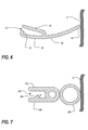
- FIG. 7 is an end cross-sectional view of another alternate embodiment of a seal 250 of a rail seal 40, shown adjacent a side panel 14 of an electronic equipment enclosure 10.
- the seal 250 has many attributes of the seals 50,150 addressed hereinabove in connection with FIGS. 4A, 4B and 5 .
- Extension arms 258,259 jointly define a channel 252 for receiving the edge of the rail seal panel 42.
- One of the extension arms 258 includes a hooked portion 256 to assist in clamping the seal 250 to the edge of the rail seal panel 42.
- the seal 250 may also include a bumper portion 266, opposite of the extension arms 258,259, to interface with another surface to help establish a seal. Additionally, the bumper portion 266 can help establish a seal against both flat surfaces and irregular surfaces.
- a rail seal 40 utilizing the seal 250 may be adapted to establish a seal against a side panel or wall that has surface features or other irregularities that create a non-flat surface, as can be seen in FIG. 7 .
- kits can be provided with rail seal panels 42 and seals 50,150,250 of varying lengths and widths.
- rail seal panels 42 may be provided with notches at ends thereof to assist in orienting and aligning the panels 42 during installation. Additionally, kits can be shipped with the seals 50,150,250 pre-attached at edges of the rail seal panels 42, thereby affording the rail seal panels 42 with additional strength and rigidity during the shipping process.
- a kit may be provided with four rail seals 40. Such a kit may specifically include four rail seal panels 42, four seals 50,150,250, sixteen fasteners 64, and twelve grommets 44.
- the rail seal 40 of the present invention is capable of ready installation in an enclosure 10 from one side of the enclosure 10.
- the rail seal 40 is readily installable from a front of the enclosure 10, which can enable the rail seal 40 to be retrofitted in an existing enclosure with relative ease.
- the rail seal 40 occupies less space within the enclosure 10 and is adaptable for use in connection with a range of different cable management features and options, such as front-to-back/back-to-front cable routing, and/or front-to-back/back-to-front airflow control.
- FIG. 8 is an isometric view of the electronic equipment enclosure 10 of FIG. 1A , shown with upper and lower rail seals 84,86 attached horizontally at respective upper and lower ends of the pair of vertical mounting rails 30, and
- FIG. 9 is a front cross-sectional view of the electronic equipment enclosure 10 of FIG. 8 , taken along line 9-9.
- the upper rail seal 84 attaches horizontally atop the pair of vertical mounting rails 30, thereby providing a horizontal air dam at the interior of the enclosure between the top panel and the pair of vertical mounting rails 30.
- the lower rail seal 86 attaches horizontally at the respective bases of the pair of vertical mounting rails 30 at bottom edges thereof, thereby providing a horizontal air dam at the interior of the enclosure between the bottom panel 17 and the pair of vertical mounting rails 30.
- the upper and lower rail seals 84,86 facilitate establishment of a seal between the vertical mounting rails 30 and the top panel (not illustrated) and bottom panel 17 of the enclosure 10 and thus help provide a barrier to airflow between interior portions of the enclosure 10.
- the upper and lower rail seals 84,86 may have any of a variety of different shapes and configurations as might be desired.
- FIG. 10 is an isometric view of the upper rail seal 84 of FIG. 8
- FIG. 11 is an isometric view of the lower rail seal 86 of FIG. 8
- the upper rail seal 84 includes an upper rail seal panel 92 and a seal 94
- the lower rail seal 86 includes a lower rail seal panel 96 and a seal 98.
- Each seal 94,98 may be clamped or otherwise attached along a horizontal edge of the respective upper and lower rail seal panels 92,96, thereby providing the rail seals 84,86 with flexible sealing surfaces along edges thereof.
- seals 94,98 are clamped at outer-facing edges of the rail seal panels 92,96, which may interface with and rest against respective top and bottom panels of the enclosure 10.
- the rail seals 40 provide a horizontal air dam at the interior of the enclosure 10 between the vertical mounting rails 30 and the top and bottom panels of the enclosure 10.
- Seals 94,98 may have any of a wide variety of shapes and configurations, including the configurations depicted in FIGS. 4A , 6 and 7 .
- Seals 94,98 are preferably made from a compliant, flexible material. In one contemplated embodiment, seals 94,98 are composed of a rubber material.
- the upper rail seal panel 92 is adapted to be attached at its ends via fasteners 88 to upper ends of the pair of vertical mounting rails b30.
- the lower rail seal panel 96 is adapted to be attached at its ends via fasteners 88 to lower ends of the pair of vertical mounting rails 30.
- Fasteners 88 may be any of a variety of different fastening mechanisms, such as self-tapping screws.
Abstract
An electronic equipment enclosure (10) includes a frame structure (12), one or more panels (14, 17) attached to the frame structure, at least one vertical mounting rail (30) fastened to the frame structure, and a rail seal (40) attached to the at least one vertical mounting rail. The rail seal includes a generally flat panel portion and a seal along an edge thereof. The seal is adapted to engage at least one of the one or more panels to provide an air dam between the one or more panels and the at least one vertical mounting rail.

Description
- The present invention relates generally to electronic equipment cabinet structures and enclosures, and, in particular, to rail seals for installing on vertical mounting rails in electronic equipment cabinet structures and enclosures.
- Racks, frames and cabinets for mounting and storing electronic components have been well known for many years. Frames and racks are typically simple rectangular frameworks on which electronic components may be mounted, or on which other mounting members, such as shelves or brackets, may be mounted which in turn may support the electronic components. Cabinets are typically frames on which panels or doors, or both, are hung to provide aesthetic improvement, to protect the components from external influences, to provide security for the components stored inside, or for other reasons. Racks, frames and cabinets (sometimes collectively referred to hereinafter as "enclosures") are often customized in order to best accommodate the components which they are designed to store.
- Air dam kits are commonly installed in an enclosure in order to establish a barrier between interior portions of the enclosure. In so doing, air dam kits are used to direct air flow within the enclosure to cool equipment installed therein. Many known air dam kits involve bulky, three-dimensional structures that are often difficult to install within an enclosure during initial set-up and are particularly difficult to retrofit into an existing enclosure. In a retrofitting process, side paneling may need to be removed from the enclosure in order to provide the necessary access point for properly installing the air dam kit. Additionally, known air dam kits can occupy substantial internal space within the enclosure, thereby obstructing the implementation of various cable routing accessories and equipment and compromising the flexibility of the enclosure for a wider range of uses.
- Accordingly, a need exists for a more efficient type of air dam kit that occupies less space within an enclosure and can be installed with relative ease. Further, a need exists for a type of air dam kit that can be retrofitted into an existing enclosure through a front access point. Still further, a need exists for a type of air dam kit that is readily adaptable across a wide range of enclosure features and accessories and can accommodate front-to-back cable routing.
- While many aspects and features relate to, and are described in, the context of enclosures for electronic equipment, the present invention is not limited to use only in enclosures for electronic equipment, as will become apparent from the following summaries and detailed descriptions of aspects, features, and one or more embodiments of the present invention.
- Broadly defined, the present invention according to a first aspect includes an electronic equipment enclosure that includes a frame structure, one or more panels attached to the frame structure, a vertical mounting rail fastened to the frame structure; and a rail seal attached to the vertical mounting rail. The rail seal includes a generally flat panel portion and a seal along an edge thereof. The seal is adapted to engage at least one of the one or more panels to provide a vertical air dam between the one or more panels and the vertical mounting rail.
- In features of this aspect, the rail seal may further include one or more grommet ports in the panel portion for routing of cables therethrough; the rail seal may be attachable to the vertical mounting rail with one or more self-tapping screws; the panel portion may include a notched area for accommodating a finger cable manager; the seal may include an internal cavity extending substantially the length thereof; the seal may include a hooked portion for clamping the edge of the panel portion; and the seal may be shaped as a wiper blade.
- Broadly defined, the present invention according to a second aspect includes an electronic equipment enclosure as substantially shown and described.
- Broadly defined, the present invention according to a third aspect includes a rail seal for attachment to a vertical mounting rail in an electronic equipment enclosure. The rail seal includes a generally flat panel portion, a seal along an edge thereof, and one or more grommet ports in the panel portion for routing of cables therethrough. The seal is adapted to engage a panel of an electronic equipment enclosure to provide a vertical air dam therein.
- In feature of this aspect, the rail seal may be attachable with one or more self-tapping screws; the panel portion may include a notched area for accommodating a finger cable manager; the seal may include an internal cavity extending substantially the length thereof; the seal may include a hooked portion for clamping the edge of the panel portion; and the seal may be shaped as a wiper blade.
- Broadly defined, the present invention according to a fourth aspect includes a rail seal, for attachment to a vertical mounting rail in an electronic equipment enclosure, as substantially shown and described.
- Broadly defined, the present invention according to a fifth aspect includes a method of installing a rail seal in an electronic equipment enclosure. The method includes the steps of providing a frame structure and one or more panels attached thereto to define an enclosure; clamping a seal along an edge of a panel portion to form a rail seal; attaching the rail seal to a vertical mounting rail fastened to the frame structure; and aligning the seal to rest along at least one of the one or more panels, thereby forming a vertical air dam between the one or more panels and the vertical mounting rail.
- In features of this aspect, the rail seal may be attached to the vertical mounting rail with self-tapping screws; the rail seal may include one or more grommet ports extending therethrough; the method may further include the step of routing one or more cables through the one or more grommet ports; the panel portion may include a notched area for accommodating a finger cable manager; the seal may include an internal cavity extending substantially the length thereof; the seal may include a hooked portion for clamping the edge of the panel portion; and the seal may be shaped as a wiper blade.
- Broadly defined, the present invention according to a sixth aspect includes a method of installing a rail seal in an electronic equipment enclosure as substantially shown and described.
- Broadly defined, the present invention according to a seventh aspect includes a rail seal kit for providing a vertical air dam in an electronic equipment enclosure, the kit including a panel portion and a seal attachable along an edge thereof.
- In features of this aspect, the panel portion may include one or more grommet ports for routing of cables therethrough; the seal may include an internal cavity extending substantially the length thereof; the seal may include a hooked portion for clamping the edge of the panel portion; and the seal may be shaped as a wiper blade.
- Broadly defined, the present invention according to an eighth aspect includes a rail seal kit substantially as shown and described.
- Broadly defined, the present invention according to a ninth aspect includes an electronic equipment enclosure. The electronic equipment enclosure includes a frame structure, one or more panels attached to the frame structure, at least one vertical mounting rail fastened to the frame structure, and a rail seal attached to the at least one vertical mounting rail. The rail seal includes a generally flat panel portion and a seal along an edge thereof. The seal is adapted to engage at least one of the one or more panels to provide an air dam between the one or more panels and the at least one vertical mounting rail.
- In features of this aspect, the rail seal may further include one or more grommet ports in the panel portion for routing of cables therethrough; the rail seal may be attached to the at least one vertical mounting rail with one or more fasteners; and the fasteners may be self-tapping screws.
- In further features of this aspect, the panel portion may include a notched area for accommodating a cable manager bracket mounted along a side of the at least one vertical mounting rail; and the cable manager bracket, together with a finger cable manager mounted along an opposite side of the at least one vertical mounting rail, may define a cable manager.
- In further features of this aspect, the seal may include an internal cavity extending substantially the length thereof; the seal may include a hooked portion for clamping the edge of the panel portion; the seal may be shaped as a wiper blade; the seal may include a bumper portion for engagement with the one or more panels; and the seal may be composed of a rubber material.
- In still further features of this aspect, the rail seal may be fastened vertically along an edge of the at least one vertical mounting rail, with the seal engaging a side panel, thereby providing a vertical air dam between the side panel and the at least one vertical mounting rail; the rail seal may be fastened horizontally between a pair of vertical mounting rails at upper horizontal ends thereof, with the seal engaging a top panel, thereby providing a horizontal air dam between the top panel and the pair of vertical mounting rails; and the rail seal may be fastened horizontally between a pair of vertical mounting rails at lower horizontal ends thereof, with the seal engaging a bottom panel, thereby providing a horizontal air dam between the bottom panel and the pair of vertical mounting rails.
- Broadly defined, the present invention according to a tenth aspect includes a rail seal for attachment to a vertical mounting rail in an electronic equipment enclosure. The rail seal includes a generally flat panel portion, a seal along an edge thereof, and one or more grommet ports in the panel portion for routing of cables therethrough. The seal is adapted to engage a panel of an electronic equipment enclosure to provide an air dam therein.
- In features of this aspect, the rail seal may be attachable with one or more fasteners; the fasteners may be self-tapping screws; the panel portion may include a notched area for accommodating a cable manager bracket; the seal may include an internal cavity extending substantially the length thereof; the seal may include a hooked portion for clamping the edge of the panel portion; the seal may be shaped as a wiper blade; the seal may include a bumper portion; and the seal may be composed of a rubber material.
- Broadly defined, the present invention according to an eleventh aspect includes a method of installing a rail seal in an electronic equipment enclosure. The method includes providing a frame structure and one or more panels attached thereto to define an enclosure, clamping a seal along an edge of a panel portion to form a rail seal, attaching the rail seal to at least one vertical mounting rail fastened to the frame structure, and aligning the seal to rest along at least one of the one or more panels, thereby forming an air dam between the one or more panels and the at least one vertical mounting rail.
- In features of this aspect, attaching the rail seal may include attaching the rail seal to the at least one vertical mounting rail with fasteners; and the fasteners may be self-tapping screws.
- In further features of this aspect, the rail seal may include one or more grommet ports extending therethrough; and the method may further include routing one or more cables through the one or more grommet ports.
- In further features of this aspect, the seal may include an internal cavity extending substantially the length thereof; the seal may include a hooked portion for clamping the edge of the panel portion; the seal may be shaped as a wiper blade; the seal may include a bumper portion; and the seal may be composed of a rubber material.
- In another feature of this aspect, attaching the rail seal may include fastening the rail seal vertically along an edge of the at least one vertical mounting rail, and aligning the seal may include aligning the seal to rest along a side panel, thereby forming a vertical air dam between the side panel and the at least one vertical mounting rail.
- In another feature of this aspect, attaching the rail seal may include fastening the rail seal horizontally between a pair of vertical mounting rails at upper horizontal ends thereof, and aligning the seal may include aligning the seal to rest along a top panel, thereby forming a horizontal air dam between the top panel and the pair of vertical mounting rails.
- In still another feature of this aspect, attaching the rail seal may include fastening the rail seal horizontally between a pair of vertical mounting rails at lower horizontal ends thereof, and aligning the seal may include aligning the seal to rest along a bottom panel, thereby forming a horizontal air dam between the bottom panel and the pair of vertical mounting rails.
- Broadly defined, the present invention according to a twelfth aspect includes a rail seal kit for providing an air dam in an electronic equipment enclosure. The kit includes a panel portion and a seal attachable along an edge thereof.
- In features of this aspect, the panel portion may include one or more grommet ports for routing of cables therethrough; the seal may include an internal cavity extending substantially the length thereof; the seal may include a hooked portion for clamping the edge of the panel portion; the seal may be shaped as a wiper blade; the seal may include a bumper portion; and the seal may be composed of a rubber material.
- In further features of this aspect, the panel portion may be adapted to be fastened vertically in an electronic equipment enclosure along an edge of a vertical mounting rail mounted therein; the panel portion may be adapted to be fastened horizontally in an electronic equipment enclosure at respective upper horizontal edges of a pair of vertical mounting rails mounted therein; and the panel portion may be adapted to be fastened horizontally in an electronic equipment enclosure at respective lower horizontal edges of a pair of vertical mounting rails mounted therein.
- Further areas of applicability of the present invention will become apparent from the detailed description provided hereinafter. It should be understood that the detailed description and specific examples indicate a preferred embodiment of the invention, and are intended for purposes of illustration only.
- Various embodiments of the present invention, which are given by way of example only, will become apparent from the following detailed description with reference to the drawings, wherein:
-
FIG. 1A is an isometric view of an electronic equipment enclosure, shown with several panels removed to reveal a pair of vertical mounting rails installed therein, each with a pair of rail seals in accordance with one or more preferred embodiments of the present invention; -
FIG. 1B is a front cross-sectional view of the electronic equipment enclosure ofFIG. 1A , taken along line 1B—1B; -
FIG. 2A is an orthogonal partially exploded view of a rail seal panel of one of the rail seals ofFIG. 1A ; -
FIG. 2B is an isometric view of one of the vertical mounting rails ofFIG. 1A ; -
FIG. 3 is an orthogonal partially exploded view of a plurality of rail seals in accordance withFIG. 1A ; -
FIG. 4A is an end cross-sectional view of a seal of one of the rail seals ofFIG. 3 , taken alongline 4A-4A; -
FIG. 4B is an end cross-sectional view of another one of the rail seals ofFIG. 3 , shown adjacent a side panel of the electronic equipment enclosure, taken along line 4B—4B; -
FIG. 5 is an enlarged fragmentary isometric view of a portion of a rail seal similar to one of the rail seals ofFIG. 1A but shown installed with a vertical cable manager on a vertical mounting rail; -
FIG. 6 is an end cross-sectional view of an alternate embodiment of a seal of a rail seal, shown adjacent a side panel of an electronic equipment enclosure; -
FIG. 7 is an end cross-sectional view of another alternate embodiment of a seal of a rail seal, shown adjacent a side panel of an electronic equipment enclosure; -
FIG. 8 is an isometric view of the electronic equipment enclosure ofFIG. 1A , shown with upper and lower rail seals attached horizontally at respective upper and lower ends of the pair of vertical mounting rails; -
FIG. 9 is a front cross-sectional view of the electronic equipment enclosure ofFIG. 8 , taken along line 9-9; -
FIG. 10 is an isometric view of the upper rail seal ofFIG. 8 ; and -
FIG. 11 is an isometric view of the lower rail seal ofFIG. 8 . - As a preliminary matter, it will readily be understood by one having ordinary skill in the relevant art ("Ordinary Artisan") that the present invention has broad utility and application. Furthermore, any embodiment discussed and identified as being "preferred" is considered to be part of a best mode contemplated for carrying out the present invention. Other embodiments also may be discussed for additional illustrative purposes in providing a full and enabling disclosure of the present invention. Moreover, many embodiments, such as adaptations, variations, modifications, and equivalent arrangements, will be implicitly disclosed by the embodiments described herein and fall within the scope of the present invention.
- Accordingly, while one or more embodiments of the present invention is/are described herein in detail, it is to be understood that this disclosure is illustrative and exemplary of the present invention. It is not intended that the scope of patent protection afforded the present invention be defined by reading into any claim a limitation found herein that does not explicitly appear in the claim itself.
- Thus, for example, any sequence(s) and/or temporal order of steps of various processes or methods that are described herein are illustrative and not restrictive. Accordingly, it should be understood that, although steps of various processes or methods may be shown and described as being in a sequence or temporal order, the steps of any such processes or methods are not limited to being carried out in any particular sequence or order, absent an indication otherwise. Indeed, the steps in such processes or methods generally may be carried out in various different sequences and orders while still falling within the scope of the present invention. Accordingly, it is intended that the scope of patent protection afforded the present invention is to be defined by the appended claims rather than the description set forth herein.
- Additionally, it is important to note that each term used herein refers to that which the Ordinary Artisan would understand such term to mean based on the contextual use of such term herein. To the extent that the meaning of a term used herein-as understood by the Ordinary Artisan based on the contextual use of such term-differs in any way from any particular dictionary definition of such term, it is intended that the meaning of the term as understood by the Ordinary Artisan should prevail.
- Furthermore, it is important to note that, as used herein, "a" and "an" each generally denotes "at least one," but does not exclude a plurality unless the contextual use dictates otherwise. Thus, reference to "a picnic basket having an apple" describes "a picnic basket having at least one apple" as well as "a picnic basket having apples." In contrast, reference to "a picnic basket having a single apple" describes "a picnic basket having only one apple."
- When used herein to join a list of items, "or" denotes "at least one of the items," but does not exclude a plurality of items of the list. Thus, reference to "a picnic basket having cheese or crackers" describes "a picnic basket having cheese without crackers," "a picnic basket having crackers without cheese," and "a picnic basket having both cheese and crackers." Finally, when used herein to join a list of items, "and" denotes "all of the items of the list." Thus, reference to "a picnic basket having cheese and crackers" describes "a picnic basket having cheese, wherein the picnic basket further has crackers," as well as describes "a picnic basket having crackers, wherein the picnic basket further has cheese."
- Referring now to the drawings, in which like numerals represent like components throughout the several views, the preferred embodiments of the present invention are next described. The following description of one or more preferred embodiment(s) is merely exemplary in nature and is in no way intended to limit the invention, its application, or uses.
-
FIG. 1A is an isometric cross-sectional view of an electronic equipment enclosure 10, shown with several panels removed to reveal a pair of vertical mounting rails 30 installed therein, each with a pair of rail seals 40 in accordance with one or more preferred embodiments of the present invention, andFIG. 1B is a front cross-sectional view of the electronic equipment enclosure 10 ofFIG. 1A , taken along line 1B—1B. The electronic equipment enclosure 10 includes a frame structure 12 formed of four vertical support posts 16, upper and lower front cross members (not illustrated), upper and lowerrear cross members 19,20 and three pairs ofside cross members rear cross members 19,20, respectively. The front cross members and their respective support posts thus define a front frame (not illustrated), and therear cross members 19,20 and their respective support posts 16 define arear frame 26. The front and rear frames may be connected together at their respective corners by the upper, middle and lowerside cross members - Although the particular enclosure 10 and frame structure 12 described and illustrated herein may include various novel aspects, it will be apparent to the Ordinary Artisan that various aspects of the present invention are likewise applicable to enclosures and structures of generally conventional design and construction. Furthermore, various different connection means may be used to join the various members together. One novel connection means is illustrated in
FIG. 1A . However, although not illustrated herein, it will be apparent to the Ordinary Artisan that in at least some embodiments, any of a variety of other connection means may be used instead. In this regard, other examples of conventional connection means are described in commonly-assignedU.S. Patent No. 6,185,098 ,U.S. Patent No. 7,119,282 ,U.S. Patent No. 7,697,285 , U.S. Patent Application Publication No.US 2009/0190307 A1 , U.S. Patent Application Publication No.US 2009/0227197 A1 , U.S. Patent Application Publication No.US 2009/0283488 A1 , and U.S. Patent Application Publication No.US 2010/0172092 A1 . Although likewise not illustrated herein, the precision and the stability of each of the corners of at least some types of four post frame structures may be enhanced by utilizing a self-squaring corner attachment bracket such as that disclosed by the commonly-assignedU.S. Patent No. 5,997,117 entitled "RACK FRAME CABINET,". - Still further, it will be evident to the Ordinary Artisan that in at least some embodiments, other structural arrangements may be used to form a frame structure on which panels may be mounted to form an enclosure. For example, in at least one embodiment (not illustrated), a frame structure may be formed from only two support posts.
- The enclosure 10 may further include a plurality of panels, attached to the frame structure 12, which partially or fully enclose the frame structure 12. In contemplated embodiments, the enclosure 10 may include a right and/or left panels 14 (a left panel being illustrated in
FIG. 1A ), a front panel (not illustrated), and a rear panel (not illustrated), one or more of which may be configured to operate as a door to the interior of the enclosure 10. The enclosure 10 may further include a bottom panel 17 as well as a generally flat top panel (not illustrated). The top panel may be sized and shaped to fit an opening defined by the four vertical support posts 16 in connection with the upper front cross member, the upper rear cross member 19, and the upperside cross members 21. The enclosure 10 may include a wide variety of different panel configurations, connection means and other features, such as those that are described in commonly-assigned provisional patent application serial nos.61/381,904 61/381,905 - As shown in
FIG. 1A and1B , the enclosure 10 further includes one or more vertical mountingrails 30 that extend therein in a generally vertical orientation and are fastened to the frame structure 12. One contemplated mechanism for fastening the vertical mountingrail 30 to the frame structure 12 is described in commonly-assigned provisional patent application serial no.61/381,912 rail 30 typically has a series ofholes 32 formed therein to facilitate easy mounting of a wide variety of equipment to the frame structure 12. - As further shown in
FIG. 1A and1B , a pair of rail seals 40 is attached to each of the vertical mounting rails 30. The rail seals 40 attach to a portion of the corresponding vertical mountingrail 30 and thereby provide a vertical air dam, in the interior of the enclosure 10, between the side panels 14 and the vertical mounting rails 30. The rail seals 40 may have any of a variety of different shapes and configurations. For instance, the rail seals 40 may be sized to correspond with an enclosure having any desired height and a width larger than 600 millimeters. In contemplated embodiments, the rail seals 40 are sized to correspond with an enclosure having a width of 750 millimeters and/or an enclosure having a width of 800 millimeters. As will be explained in greater detail below, eachrail seal 40 includes arail seal panel 42 and aseal 50. Theseal 50 is preferably made from a compliant, flexible material. In one contemplated embodiment, theseal 50 is composed of a rubber material. In another contemplated embodiment, portions of theseal 50, such as the portion that engages a panel, are made from brush bristles (not illustrated). -
FIG. 2A is an orthogonal partially exploded view of arail seal panel 42 of one of the rail seals 40 ofFIG. 1A .FIG. 2B is an isometric view of one of the vertical mounting rails 30 ofFIG. 1A . As shown inFIG. 2A , therail seal panel 42 is generally flat and includes a plurality ofgrommets 44, each corresponding to agrommet port 46 extending through therail seal panel 42. Thegrommets 44 are configured to be removable from therail seal panel 42 such that cables are permitted to be routed through the resultinggrommet port 46. In this regard, it will be appreciated that thegrommets 44 may include an adjustable opening feature such that openings in the grommets may be created or closed off without removing the grommets from thegrommet ports 46. Therail seal panel 42 may accommodate any quantity or shape ofgrommets 44 andcorresponding grommet ports 46. In one contemplated embodiment, shown in the drawings, therail seal panel 42 includes threecircular grommets 44, each with a three-inch diameter, and three correspondingcircular grommet ports 46. Therail seal panel 42 is composed of a metal-based material. - The
rail seal panel 42 is adapted to be attached viafasteners 64 to a vertical mountingrail 30, such as that which is shown inFIG. 2B . In particular, thereal seal panel 42 includes a plurality ofapertures 48 for accommodatingfasteners 64.Fasteners 64, which may be any of a variety of different fastening mechanisms, extend through theapertures 48 and secure therail seal panel 42 flatly against asurface 31 of a vertical mountingrail 30. In one contemplated embodiment, thefasteners 64 are self-tapping screws, such as M5 x 8 millimeter self-tapping screws. As shown inFIG. 2A , therail seal panel 42 may have fourapertures 48 to accommodate four fasteners to mount therail seal panel 42 to a vertical mountingrail 30. - It will be appreciated that
openings 33 may be provided in thesurface 31 of the vertical mountingrail 30 to correspond and align with thegrommet ports 46 so as to allow cables and/or air to be routed through thegrommet ports 46 when therail seal panel 42 is mounted on the vertical mountingrail 30. In particular, as perhaps most apparent from a close inspection ofFIG. 1A relative toFIG. 2B , eachgrommet port 46 may be centered on a largerectangular opening 33 in themain surface 31 of the vertical mountingrail 30. In the contemplated embodiment, seven largerectangular openings 33 are provided, with all but the middle opening being aligned with agrommet port 46. - As further shown in
FIG. 2A , therail seal panel 42 may also include one or more notchedareas 62 for accommodating additional cable management accessories implemented in the enclosure 10. In one contemplated embodiment, shown inFIG. 5 , the notchedareas 62 may be shaped to accommodate acable manager bracket 70. -
FIG. 3 is an orthogonal partially exploded view of a plurality of rail seals 40 in accordance withFIG. 1A . As shown inFIG. 3 , seals 50 may be clamped or otherwise attached along edges of therail seal panels 42, thereby providing the rail seals 40 with a flexible sealing surface at edges thereof. In particular, theseals 50 are clamped at outer-facing edges of therail seal panels 42, which may interface with and rest against one or more side panels 14 of the enclosure 10. In this regard, the rail seals 40 provide a vertical air dam at the interior of the enclosure 10 between the side panels 14 and the vertical mounting rails 30. As further shown inFIG. 3 , rail seals 40 may be aligned in an end-to-end relationship with one another. -
FIG. 4A is an end cross-sectional view of aseal 50 of one of the rail seals 40 ofFIG. 3 , taken alongline 4A-4A; andFIG. 4B is an end cross-sectional view of another one of the rail seals 40 ofFIG. 3 , shown adjacent a side panel 14 of the electronic equipment enclosure 10, taken along line 4B—4B. As shown inFIGS. 4A and 4B , theseal 50 of arail seal 40 includes a pair ofextension arms rail seal panel 42. Together, theextension arms channel 52 for receiving the edge of therail seal panel 42. Theseal 50 may also include a flexibleinterior cavity 54 at the opposite side from theextension arms extension arms interior cavity 54 may extend along the full length of theseal 50. Theseal 50 may also include notched ends 60 adjacent theinterior cavity 54, which may interface with another surface to help establish a seal. One of theextension arms 58 may include a hookedportion 56 to assist in clamping theseal 50 to the edge of therail seal panel 42, as can perhaps best be seen inFIG. 4B . When attached, the hookedportion 56 may be deformed slightly in order to clamp the edge of therail seal panel 42. - When the
rail seal 40 is installed on a vertical mountingrail 30 in an electronic equipment enclosure 10, theseal 50 is pressed against a side panel 14 of the enclosure 10. The notched ends 60 interface with the side panel 14, thereby establishing a seal between the side panel 14 and the vertical mountingrail 30. The force exerted by therail seal 40, when pressed firmly against the side panel 14, may be evenly distributed throughout theinternal cavity 54, thereby enhancing the effectiveness of the seal. Furthermore, with a flexible sealing surface, theseal 50 can help establish a seal against both flat surfaces and irregular surfaces. For instance, in one contemplated embodiment, therail seal 40 may be adapted to establish a seal against a side panel or wall that has surface features or other irregularities that create a non-flat surface, as can be seen inFIG. 4B . -
FIG. 5 is an enlarged fragmentary isometric view of a portion of a rail seal similar to one of the rail seals 40 ofFIG. 1A but shown installed with avertical cable manager 90 on a vertical mountingrail 30. InFIG. 5 , and with further reference toFIG. 2B , therail seal panel 42 is shown secured to a flat,front surface 31 of the vertical mountingrail 30.Cable manager brackets 70 are shown extending through the notchedareas 62 between theseal 50 and therail seal panel 42. Thecable manager brackets 70 may be used in connection with one or morefinger cable managers 74 extending from the opposite side of the vertical mountingrail 30 to establish a cable manager 90 (as explained below). In order to further accommodate thecable manager brackets 70, theseal 50 may itself include one or more notched areas or slits 72 at a portion of the inner edge thereof. Advantageously, therail seal 40 may be installed in an enclosure 10 with or withoutcable manager brackets 70. - As shown in
FIG. 5 , thecable manager bracket 70 may be used in connection with one or morefinger cable managers 74 to establish acable manager 90 at the vertical mountingrail 30. Thefinger cable managers 74 each include a plurality ofcable guide projections 76 for supporting and guiding individual cables into and out of thecable manager 90. Additionally, eachcable manager bracket 70 itself may include anopening 80 to permit cable pass-through into and out of thecable manager 90. Acover 78 may be supported by the distal ends of thefinger cable managers 74 and thecable manger brackets 70 to further define and enclose thecable manager 90. The cover is hingedly attached to one or both of thefinger cable managers 74 and thecable manager brackets 70 so as to permit ready access to cables supported in thecable manager 90. As shown inFIG. 5 , multiplecable manager brackets 70 may be used to help support thecover 78. -
FIG. 6 is an end cross-sectional view of an alternate embodiment of a seal 150 of arail seal 40, shown adjacent a side panel 14 of an electronic equipment enclosure 10. As shown inFIG. 6 , the seal 150 has many attributes of theseal 50 addressed hereinabove in connection withFIGS. 4A and 4B . Extension arms 158,159 jointly define a channel 152 for receiving the edge of therail seal panel 42. One of the extension arms 158 includes a hooked portion 156 to assist in clamping the seal 150 to the edge of therail seal panel 42. The seal 150 may also include a flexible wiper blade end 166, opposite of the extension arms 158,159, to interface with another surface to help establish a seal. Additionally, with the flexible wiper blade end 166, the seal 150 can help establish a seal against both flat surfaces and irregular surfaces. For instance, in one contemplated embodiment, arail seal 40 utilizing the seal 150 may be adapted to establish a seal against a side panel or wall that has surface features or other irregularities that create a non-flat surface, as can be seen inFIG. 6 . -
FIG. 7 is an end cross-sectional view of another alternate embodiment of a seal 250 of arail seal 40, shown adjacent a side panel 14 of an electronic equipment enclosure 10. As shown inFIG. 7 , the seal 250 has many attributes of the seals 50,150 addressed hereinabove in connection withFIGS. 4A, 4B and5 . Extension arms 258,259 jointly define achannel 252 for receiving the edge of therail seal panel 42. One of theextension arms 258 includes a hookedportion 256 to assist in clamping the seal 250 to the edge of therail seal panel 42. The seal 250 may also include abumper portion 266, opposite of the extension arms 258,259, to interface with another surface to help establish a seal. Additionally, thebumper portion 266 can help establish a seal against both flat surfaces and irregular surfaces. For instance, in one contemplated embodiment, arail seal 40 utilizing the seal 250 may be adapted to establish a seal against a side panel or wall that has surface features or other irregularities that create a non-flat surface, as can be seen inFIG. 7 . - The
rail seal 40, as discussed hereinabove, may be provided in the form of, and assembled from, a kit. Kits can be provided withrail seal panels 42 and seals 50,150,250 of varying lengths and widths. In a particular kit,rail seal panels 42 may be provided with notches at ends thereof to assist in orienting and aligning thepanels 42 during installation. Additionally, kits can be shipped with the seals 50,150,250 pre-attached at edges of therail seal panels 42, thereby affording therail seal panels 42 with additional strength and rigidity during the shipping process. In one contemplated embodiment, a kit may be provided with four rail seals 40. Such a kit may specifically include fourrail seal panels 42, four seals 50,150,250, sixteenfasteners 64, and twelvegrommets 44. - As can be appreciated by the Ordinary Artisan, the
rail seal 40 of the present invention is capable of ready installation in an enclosure 10 from one side of the enclosure 10. In particular, therail seal 40 is readily installable from a front of the enclosure 10, which can enable therail seal 40 to be retrofitted in an existing enclosure with relative ease. Additionally, with a generally flat shape and a plurality ofgrommet ports 46, therail seal 40 occupies less space within the enclosure 10 and is adaptable for use in connection with a range of different cable management features and options, such as front-to-back/back-to-front cable routing, and/or front-to-back/back-to-front airflow control. -
FIG. 8 is an isometric view of the electronic equipment enclosure 10 ofFIG. 1A , shown with upper and lower rail seals 84,86 attached horizontally at respective upper and lower ends of the pair of vertical mounting rails 30, andFIG. 9 is a front cross-sectional view of the electronic equipment enclosure 10 ofFIG. 8 , taken along line 9-9. As shown inFIGS. 8 and9 , theupper rail seal 84 attaches horizontally atop the pair of vertical mounting rails 30, thereby providing a horizontal air dam at the interior of the enclosure between the top panel and the pair of vertical mounting rails 30. In similar fashion, thelower rail seal 86 attaches horizontally at the respective bases of the pair of vertical mounting rails 30 at bottom edges thereof, thereby providing a horizontal air dam at the interior of the enclosure between the bottom panel 17 and the pair of vertical mounting rails 30. In this manner, the upper and lower rail seals 84,86 facilitate establishment of a seal between the vertical mounting rails 30 and the top panel (not illustrated) and bottom panel 17 of the enclosure 10 and thus help provide a barrier to airflow between interior portions of the enclosure 10. Advantageously, the upper and lower rail seals 84,86 may have any of a variety of different shapes and configurations as might be desired. -
FIG. 10 is an isometric view of theupper rail seal 84 ofFIG. 8 , andFIG. 11 is an isometric view of thelower rail seal 86 ofFIG. 8 . As shown inFIG. 10 , theupper rail seal 84 includes an upperrail seal panel 92 and aseal 94. Likewise, as shown inFIG. 11 , thelower rail seal 86 includes a lowerrail seal panel 96 and a seal 98. Eachseal 94,98 may be clamped or otherwise attached along a horizontal edge of the respective upper and lowerrail seal panels rail seal panels Seals 94,98 may have any of a wide variety of shapes and configurations, including the configurations depicted inFIGS. 4A ,6 and 7 .Seals 94,98 are preferably made from a compliant, flexible material. In one contemplated embodiment, seals 94,98 are composed of a rubber material. - The upper
rail seal panel 92 is adapted to be attached at its ends viafasteners 88 to upper ends of the pair of vertical mounting rails b30. Likewise, the lowerrail seal panel 96 is adapted to be attached at its ends viafasteners 88 to lower ends of the pair of vertical mounting rails 30.Fasteners 88 may be any of a variety of different fastening mechanisms, such as self-tapping screws. - Based on the foregoing information, it will be readily understood by those persons skilled in the art that the present invention is susceptible of broad utility and application. Many embodiments and adaptations of the present invention other than those specifically described herein, as well as many variations, modifications, and equivalent arrangements, will be apparent from or reasonably suggested by the present invention and the foregoing descriptions thereof, without departing from the substance or scope of the present invention.
- Accordingly, while one or more preferred embodiments of the present invention has been described herein in detail, it is to be understood that this disclosure is only illustrative and exemplary of the present invention.
Claims (15)
- An electronic equipment enclosure comprising:(a) a frame structure;(b) one or more panels attached to the frame structure;(c) at least one vertical mounting rail fastened to the frame structure; and(d) a rail seal attached to the at least one vertical mounting rail and including a generally flat panel portion and a seal along an edge thereof;(e) wherein the seal is adapted to engage at least one of the one or more panels to provide an air dam between the one or more panels and the at least one vertical mounting rail.
- The electronic equipment enclosure of claim 1, wherein the rail seal further includes one or more grommet ports in the panel portion for routing of cables therethrough.
- The electronic equipment enclosure of claim 1 or claim 2, wherein the rail seal is attached to the at least one vertical mounting rail with one or more fasteners.
- The electronic equipment enclosure of claim 3, wherein the fasteners are self-tapping screws.
- The electronic equipment enclosure of any preceding claim, wherein the panel portion includes a notched area for accommodating a cable manager bracket mounted along a side of the at least one vertical mounting rail.
- The electronic equipment enclosure of claim 5, wherein the cable manager bracket, together with a finger cable manager mounted along an opposite side of the at least one vertical mounting rail, defines a cable manager.
- The electronic equipment enclosure of any preceding claim, wherein the seal includes a hooked portion for clamping the edge of the panel portion.
- The electronic equipment enclosure of any preceding claim, wherein the seal is shaped as a wiper blade.
- The electronic equipment enclosure of any preceding claim, wherein the rail seal is fastened vertically along an edge of the at least one vertical mounting rail, with the seal engaging a side panel, thereby providing a vertical air dam between the side panel and the at least one vertical mounting rail.
- The electronic equipment enclosure of any preceding claim, wherein the rail seal is fastened horizontally between a pair of vertical mounting rails at upper horizontal ends thereof, with the seal engaging a top panel, thereby providing a horizontal air dam between the top panel and the pair of vertical mounting rails.
- The electronic equipment enclosure of any preceding claim, wherein the rail seal is fastened horizontally between a pair of vertical mounting rails at lower horizontal ends thereof, with the seal engaging a bottom panel, thereby providing a horizontal air dam between the bottom panel and the pair of vertical mounting rails.
- A method of installing a rail seal in an electronic equipment enclosure, the method comprising:(a) providing a frame structure and one or more panels attached thereto to define an enclosure;(b) clamping a seal along an edge of a panel portion to form a rail seal;(c) attaching the rail seal to at least one vertical mounting rail fastened to the frame structure; and(d) aligning the seal to rest along at least one of the one or more panels, thereby forming an air dam between the one or more panels and the at least one vertical mounting rail.
- The method of claim 12, wherein:(a) attaching the rail seal includes fastening the rail seal vertically along an edge of the at least one vertical mounting rail; and(b) aligning the seal includes aligning the seal to rest along a side panel, thereby forming a vertical air dam between the side panel and the at least one vertical mounting rail.
- The method of claim 12 or claim 13, wherein:(a) attaching the rail seal includes fastening the rail seal horizontally between a pair of vertical mounting rails at upper horizontal ends thereof; and(b) aligning the seal includes aligning the seal to rest along a top panel, thereby forming a horizontal air dam between the top panel and the pair of vertical mounting rails.
- The method of any of claims 12, 13 or 14, wherein:(a) attaching the rail seal includes fastening the rail seal horizontally between a pair of vertical mounting rails at lower horizontal ends thereof; and(b) aligning the seal includes aligning the seal to rest along a bottom panel, thereby forming a horizontal air dam between the bottom panel and the pair of vertical mounting rails.
Applications Claiming Priority (1)
| Application Number | Priority Date | Filing Date | Title |
|---|---|---|---|
| US38190910P | 2010-09-10 | 2010-09-10 |
Publications (1)
| Publication Number | Publication Date |
|---|---|
| EP2429271A2 true EP2429271A2 (en) | 2012-03-14 |
Family
ID=44582738
Family Applications (1)
| Application Number | Title | Priority Date | Filing Date |
|---|---|---|---|
| EP11275110A Withdrawn EP2429271A2 (en) | 2010-09-10 | 2011-09-09 | Rail seal for electronic equipment enclosure |
Country Status (2)
| Country | Link |
|---|---|
| US (1) | US20120063099A1 (en) |
| EP (1) | EP2429271A2 (en) |
Cited By (12)
| Publication number | Priority date | Publication date | Assignee | Title |
|---|---|---|---|---|
| US8424691B2 (en) | 2008-05-19 | 2013-04-23 | Chatsworth Products, Inc. | Seismically hardened two-post electronic equipment rack |
| US8787023B2 (en) | 2010-09-10 | 2014-07-22 | Chatsworth Products, Inc. | Rail mounting clamp for electronic equipment enclosure |
| US8901438B2 (en) | 2010-09-10 | 2014-12-02 | Chatsworth Products, Inc. | Electronic equipment cabinet structure |
| US9055677B2 (en) | 2010-09-10 | 2015-06-09 | Chatsworth Products, Inc. | Cable pass-through panel for electronic equipment enclosure |
| US9549487B2 (en) | 2013-12-17 | 2017-01-17 | Chatsworth Products, Inc. | Electronic equipment enclosure |
| US9560777B2 (en) | 2010-11-08 | 2017-01-31 | Chatsworth Products, Inc. | Door closer mechanism for hot/cold aisle air containment room |
| US9572286B2 (en) | 2013-01-11 | 2017-02-14 | Chatsworth Products, Inc. | Modular thermal isolation barrier for data processing equipment structure |
| US11246231B2 (en) | 2012-02-10 | 2022-02-08 | Chatsworth Products, Inc. | Door closer mechanism for hot/cold aisle air containment room |
| US11622458B1 (en) | 2020-12-15 | 2023-04-04 | Chatsworth Products, Inc. | Brush port assembly and method for installing same |
| US11678456B1 (en) | 2020-12-15 | 2023-06-13 | Chatsworth Products, Inc. | Slidable mounting hardware for electronic equipment enclosure and method for installing same |
| US11818861B1 (en) | 2020-12-15 | 2023-11-14 | Chatsworth Products, Inc. | Frame structure for electronic equipment enclosure |
| US11920392B1 (en) | 2021-02-02 | 2024-03-05 | Chatsworth Products, Inc. | Electrical bonding door hinges |
Families Citing this family (10)
| Publication number | Priority date | Publication date | Assignee | Title |
|---|---|---|---|---|
| US9185824B2 (en) * | 2011-04-26 | 2015-11-10 | Panduit Corp. | Cable pathway system for network architecture |
| US9144175B2 (en) | 2012-06-25 | 2015-09-22 | Panduit Corp. | Electronics cabinet |
| US9943003B2 (en) | 2012-06-25 | 2018-04-10 | Panduit Corp. | Electronics cabinet |
| JP6979872B2 (en) * | 2014-09-11 | 2021-12-15 | パンドウィット・コーポレーション | Electronics cabinet |
| US9924611B2 (en) * | 2015-05-15 | 2018-03-20 | Innovation First, Inc. | Connectors to secure multiple rails in a server rack |
| US9456520B1 (en) * | 2015-09-25 | 2016-09-27 | Innovation First, Inc. | Server rack system for mounting equipment |
| US9814156B2 (en) | 2015-09-25 | 2017-11-07 | Innovation First, Inc. | Server rack system for mounting equipment |
| CA2950839C (en) * | 2016-01-30 | 2023-09-12 | Cooper Technologies Company | Equipment rack and components thereof |
| CN111615283A (en) * | 2019-02-25 | 2020-09-01 | 康普技术有限责任公司 | Cable management ring and panel for telecommunications equipment |
| US11432429B2 (en) | 2020-05-05 | 2022-08-30 | Hoffman Enclosures Inc. | Adjustable barrier for enclosures |
Citations (8)
| Publication number | Priority date | Publication date | Assignee | Title |
|---|---|---|---|---|
| US5997117A (en) | 1997-06-06 | 1999-12-07 | Chatsworth Products, Inc. | Rack frame cabinet |
| US6185098B1 (en) | 2000-01-31 | 2001-02-06 | Chatsworth Products, Inc. | Co-location server cabinet |
| US7119282B2 (en) | 2000-09-15 | 2006-10-10 | Chatsworth Products, Inc. | Vertical cable management rack |
| US20090190307A1 (en) | 2005-09-19 | 2009-07-30 | Chatsworth Products, Inc. | Ducted exhaust equipment enclosure |
| US20090227197A1 (en) | 2008-02-14 | 2009-09-10 | Chatsworth Products, Inc. | Air directing device |
| US20090283488A1 (en) | 2008-05-19 | 2009-11-19 | Chatsworth Products, Inc. | Seismically hardened two-post electronic equipment rack |
| US7697285B2 (en) | 2007-05-17 | 2010-04-13 | Chatsworth Products, Inc. | Electronic equipment enclosure with exhaust air duct and adjustable filler panel assemblies |
| US20100172092A1 (en) | 2009-01-05 | 2010-07-08 | Chatsworth Products, Inc. | Electronic equipment enclosure with side-to-side airflow control system |
Family Cites Families (6)
| Publication number | Priority date | Publication date | Assignee | Title |
|---|---|---|---|---|
| JPS5864544U (en) * | 1981-10-27 | 1983-04-30 | 豊田合成株式会社 | Automotive weather strip |
| US6008621A (en) * | 1998-10-15 | 1999-12-28 | Electronic Classroom Furniture Systems | Portable computer charging system and storage cart |
| US7112131B2 (en) * | 2003-05-13 | 2006-09-26 | American Power Conversion Corporation | Rack enclosure |
| US8107238B2 (en) * | 2005-09-19 | 2012-01-31 | Chatsworth Products, Inc. | Ducted exhaust equipment enclosure |
| US7764495B2 (en) * | 2007-04-30 | 2010-07-27 | Adc Telecommunications, Inc. | Telecommunication cabinet with airflow ducting |
| US8263867B2 (en) * | 2008-01-07 | 2012-09-11 | Chatsworth Products, Inc. | Cable management accessories |
-
2011
- 2011-09-09 EP EP11275110A patent/EP2429271A2/en not_active Withdrawn
- 2011-09-10 US US13/229,706 patent/US20120063099A1/en not_active Abandoned
Patent Citations (8)
| Publication number | Priority date | Publication date | Assignee | Title |
|---|---|---|---|---|
| US5997117A (en) | 1997-06-06 | 1999-12-07 | Chatsworth Products, Inc. | Rack frame cabinet |
| US6185098B1 (en) | 2000-01-31 | 2001-02-06 | Chatsworth Products, Inc. | Co-location server cabinet |
| US7119282B2 (en) | 2000-09-15 | 2006-10-10 | Chatsworth Products, Inc. | Vertical cable management rack |
| US20090190307A1 (en) | 2005-09-19 | 2009-07-30 | Chatsworth Products, Inc. | Ducted exhaust equipment enclosure |
| US7697285B2 (en) | 2007-05-17 | 2010-04-13 | Chatsworth Products, Inc. | Electronic equipment enclosure with exhaust air duct and adjustable filler panel assemblies |
| US20090227197A1 (en) | 2008-02-14 | 2009-09-10 | Chatsworth Products, Inc. | Air directing device |
| US20090283488A1 (en) | 2008-05-19 | 2009-11-19 | Chatsworth Products, Inc. | Seismically hardened two-post electronic equipment rack |
| US20100172092A1 (en) | 2009-01-05 | 2010-07-08 | Chatsworth Products, Inc. | Electronic equipment enclosure with side-to-side airflow control system |
Cited By (35)
| Publication number | Priority date | Publication date | Assignee | Title |
|---|---|---|---|---|
| US8424691B2 (en) | 2008-05-19 | 2013-04-23 | Chatsworth Products, Inc. | Seismically hardened two-post electronic equipment rack |
| US9642270B2 (en) | 2010-09-10 | 2017-05-02 | Chatsworth Products, Inc. | Rail seal for electronic equipment enclosure |
| US10237994B2 (en) | 2010-09-10 | 2019-03-19 | Chatsworth Products, Inc. | Vertical mounting rail with cable management features |
| US9781852B2 (en) | 2010-09-10 | 2017-10-03 | Chatsworth Products, Inc. | Cable pass-through panel for electronic equipment enclosure |
| US9814159B2 (en) | 2010-09-10 | 2017-11-07 | Chatsworth Products, Inc. | Rail seal for electronic equipment enclosure |
| US11792948B2 (en) | 2010-09-10 | 2023-10-17 | Chatsworth Products, Inc. | Cable pass-through panel for electronic equipment enclosure |
| US10588227B2 (en) | 2010-09-10 | 2020-03-10 | Chatsworth Products, Inc. | Vertical mounting rail with cable management features |
| US11464123B2 (en) | 2010-09-10 | 2022-10-04 | Chatsworth Products, Inc. | Method of adapting an electronic equipment enclosure for cable management |
| US10653025B2 (en) | 2010-09-10 | 2020-05-12 | Chatsworth Products, Inc. | Cable pass-through panel for electronic equipment enclosure |
| US11039543B2 (en) | 2010-09-10 | 2021-06-15 | Chatsworth Products, Inc. | Vertical mounting rail with cable management features |
| US9055677B2 (en) | 2010-09-10 | 2015-06-09 | Chatsworth Products, Inc. | Cable pass-through panel for electronic equipment enclosure |
| US9408326B2 (en) | 2010-09-10 | 2016-08-02 | Chatsworth Products, Inc. | Electronic equipment cabinet structure |
| US9980400B2 (en) | 2010-09-10 | 2018-05-22 | Chatsworth Products, Inc. | Rail seal for electronic equipment enclosure |
| US10178784B2 (en) | 2010-09-10 | 2019-01-08 | Chatsworth Products, Inc. | Rail seal for electronic equipment enclosure |
| US8901438B2 (en) | 2010-09-10 | 2014-12-02 | Chatsworth Products, Inc. | Electronic equipment cabinet structure |
| US8787023B2 (en) | 2010-09-10 | 2014-07-22 | Chatsworth Products, Inc. | Rail mounting clamp for electronic equipment enclosure |
| US10362695B2 (en) | 2010-11-08 | 2019-07-23 | Chatsworth Products, Inc. | Door closer mechanism for hot/cold aisle air containment room |
| US9560777B2 (en) | 2010-11-08 | 2017-01-31 | Chatsworth Products, Inc. | Door closer mechanism for hot/cold aisle air containment room |
| US11246231B2 (en) | 2012-02-10 | 2022-02-08 | Chatsworth Products, Inc. | Door closer mechanism for hot/cold aisle air containment room |
| US10375861B2 (en) | 2013-01-11 | 2019-08-06 | Chatsworth Products, Inc. | Modular thermal isolation barrier for data processing equipment structure |
| US11647610B2 (en) | 2013-01-11 | 2023-05-09 | Chatsworth Products, Inc. | Modular thermal isolation barrier for data processing equipment structure |
| US10595442B2 (en) | 2013-01-11 | 2020-03-17 | Chatsworth Products, Inc. | Data processing equipment structure |
| US9795060B2 (en) | 2013-01-11 | 2017-10-17 | Chatsworth Products, Inc. | Modular thermal isolation barrier for data processing equipment structure |
| US9572286B2 (en) | 2013-01-11 | 2017-02-14 | Chatsworth Products, Inc. | Modular thermal isolation barrier for data processing equipment structure |
| US11083108B2 (en) | 2013-12-17 | 2021-08-03 | Chatsworth Products, Inc. | Electronic equipment enclosure |
| US9549487B2 (en) | 2013-12-17 | 2017-01-17 | Chatsworth Products, Inc. | Electronic equipment enclosure |
| US11622458B1 (en) | 2020-12-15 | 2023-04-04 | Chatsworth Products, Inc. | Brush port assembly and method for installing same |
| US11627677B1 (en) | 2020-12-15 | 2023-04-11 | Chatsworth Products, Inc. | Brush port assembly and method for installing same |
| US11678456B1 (en) | 2020-12-15 | 2023-06-13 | Chatsworth Products, Inc. | Slidable mounting hardware for electronic equipment enclosure and method for installing same |
| US11678458B1 (en) | 2020-12-15 | 2023-06-13 | Chatsworth Products, Inc. | Slidable mounting hardware for electronic equipment enclosure and method for installing same |
| US11818861B1 (en) | 2020-12-15 | 2023-11-14 | Chatsworth Products, Inc. | Frame structure for electronic equipment enclosure |
| US11818862B1 (en) | 2020-12-15 | 2023-11-14 | Chatsworth Products, Inc. | Frame structure for electronic equipment enclosure |
| US11818860B1 (en) | 2020-12-15 | 2023-11-14 | Chatsworth Products, Inc. | Frame structure for electronic equipment enclosure |
| US11903156B1 (en) | 2020-12-15 | 2024-02-13 | Chatsworth Products, Inc. | Brush port assembly and method for installing same |
| US11920392B1 (en) | 2021-02-02 | 2024-03-05 | Chatsworth Products, Inc. | Electrical bonding door hinges |
Also Published As
| Publication number | Publication date |
|---|---|
| US20120063099A1 (en) | 2012-03-15 |
Similar Documents
| Publication | Publication Date | Title |
|---|---|---|
| US10178784B2 (en) | Rail seal for electronic equipment enclosure | |
| EP2429271A2 (en) | Rail seal for electronic equipment enclosure | |
| US20120062091A1 (en) | Vertical mounting rail with cable management features | |
| US20140319084A1 (en) | Rail mounting clamp for electronic equipment enclosure | |
| US20080035810A1 (en) | Offset brackets for expanding electronic equipment cabinets | |
| US9346391B2 (en) | Modular shelving assembly | |
| US8721010B2 (en) | Equipment cabinet | |
| US20160174402A1 (en) | Mounting fixture system | |
| JP5675240B2 (en) | Mounting frame for holding electronic devices | |
| US20180055229A1 (en) | Slat panel assembly | |
| US11622458B1 (en) | Brush port assembly and method for installing same | |
| GB2282527A (en) | Mounting frame for electrical equipment | |
| US8266854B2 (en) | Grommet closure device | |
| US20110173906A1 (en) | Floor gland | |
| CA2996560C (en) | Vertical wall mount host enclosure | |
| EP1416600A1 (en) | Wall-mounted electrical housing | |
| KR100708775B1 (en) | Ventilation structure of airtight space | |
| JP2004039820A (en) | Equipment housing box | |
| CN213694501U (en) | Electrical equipment cabinet |
Legal Events
| Date | Code | Title | Description |
|---|---|---|---|
| AK | Designated contracting states |
Kind code of ref document: A2 Designated state(s): AL AT BE BG CH CY CZ DE DK EE ES FI FR GB GR HR HU IE IS IT LI LT LU LV MC MK MT NL NO PL PT RO RS SE SI SK SM TR |
|
| AX | Request for extension of the european patent |
Extension state: BA ME |
|
| PUAI | Public reference made under article 153(3) epc to a published international application that has entered the european phase |
Free format text: ORIGINAL CODE: 0009012 |
|
| RAP1 | Party data changed (applicant data changed or rights of an application transferred) |
Owner name: CHATSWORTH PRODUCTS, INC. |
|
| STAA | Information on the status of an ep patent application or granted ep patent |
Free format text: STATUS: THE APPLICATION HAS BEEN WITHDRAWN |
|
| 18W | Application withdrawn |
Effective date: 20140925 |