EP2405525A2 - Battery pack having boosting charge function and method thereof - Google Patents
Battery pack having boosting charge function and method thereof Download PDFInfo
- Publication number
- EP2405525A2 EP2405525A2 EP20110250125 EP11250125A EP2405525A2 EP 2405525 A2 EP2405525 A2 EP 2405525A2 EP 20110250125 EP20110250125 EP 20110250125 EP 11250125 A EP11250125 A EP 11250125A EP 2405525 A2 EP2405525 A2 EP 2405525A2
- Authority
- EP
- European Patent Office
- Prior art keywords
- voltage
- battery cell
- transistor
- charge
- unit
- Prior art date
- Legal status (The legal status is an assumption and is not a legal conclusion. Google has not performed a legal analysis and makes no representation as to the accuracy of the status listed.)
- Ceased
Links
Images


Classifications
-
- H—ELECTRICITY
- H02—GENERATION; CONVERSION OR DISTRIBUTION OF ELECTRIC POWER
- H02J—CIRCUIT ARRANGEMENTS OR SYSTEMS FOR SUPPLYING OR DISTRIBUTING ELECTRIC POWER; SYSTEMS FOR STORING ELECTRIC ENERGY
- H02J7/00—Circuit arrangements for charging or depolarising batteries or for supplying loads from batteries
- H02J7/02—Circuit arrangements for charging or depolarising batteries or for supplying loads from batteries for charging batteries from ac mains by converters
- H02J7/04—Regulation of charging current or voltage
-
- H—ELECTRICITY
- H01—ELECTRIC ELEMENTS
- H01M—PROCESSES OR MEANS, e.g. BATTERIES, FOR THE DIRECT CONVERSION OF CHEMICAL ENERGY INTO ELECTRICAL ENERGY
- H01M10/00—Secondary cells; Manufacture thereof
- H01M10/42—Methods or arrangements for servicing or maintenance of secondary cells or secondary half-cells
- H01M10/44—Methods for charging or discharging
-
- G—PHYSICS
- G01—MEASURING; TESTING
- G01R—MEASURING ELECTRIC VARIABLES; MEASURING MAGNETIC VARIABLES
- G01R31/00—Arrangements for testing electric properties; Arrangements for locating electric faults; Arrangements for electrical testing characterised by what is being tested not provided for elsewhere
- G01R31/36—Arrangements for testing, measuring or monitoring the electrical condition of accumulators or electric batteries, e.g. capacity or state of charge [SoC]
-
- H—ELECTRICITY
- H01—ELECTRIC ELEMENTS
- H01M—PROCESSES OR MEANS, e.g. BATTERIES, FOR THE DIRECT CONVERSION OF CHEMICAL ENERGY INTO ELECTRICAL ENERGY
- H01M10/00—Secondary cells; Manufacture thereof
- H01M10/42—Methods or arrangements for servicing or maintenance of secondary cells or secondary half-cells
- H01M10/44—Methods for charging or discharging
- H01M10/443—Methods for charging or discharging in response to temperature
-
- H—ELECTRICITY
- H01—ELECTRIC ELEMENTS
- H01M—PROCESSES OR MEANS, e.g. BATTERIES, FOR THE DIRECT CONVERSION OF CHEMICAL ENERGY INTO ELECTRICAL ENERGY
- H01M10/00—Secondary cells; Manufacture thereof
- H01M10/42—Methods or arrangements for servicing or maintenance of secondary cells or secondary half-cells
- H01M10/46—Accumulators structurally combined with charging apparatus
-
- H—ELECTRICITY
- H01—ELECTRIC ELEMENTS
- H01M—PROCESSES OR MEANS, e.g. BATTERIES, FOR THE DIRECT CONVERSION OF CHEMICAL ENERGY INTO ELECTRICAL ENERGY
- H01M10/00—Secondary cells; Manufacture thereof
- H01M10/42—Methods or arrangements for servicing or maintenance of secondary cells or secondary half-cells
- H01M10/48—Accumulators combined with arrangements for measuring, testing or indicating the condition of cells, e.g. the level or density of the electrolyte
- H01M10/486—Accumulators combined with arrangements for measuring, testing or indicating the condition of cells, e.g. the level or density of the electrolyte for measuring temperature
-
- H—ELECTRICITY
- H02—GENERATION; CONVERSION OR DISTRIBUTION OF ELECTRIC POWER
- H02H—EMERGENCY PROTECTIVE CIRCUIT ARRANGEMENTS
- H02H7/00—Emergency protective circuit arrangements specially adapted for specific types of electric machines or apparatus or for sectionalised protection of cable or line systems, and effecting automatic switching in the event of an undesired change from normal working conditions
- H02H7/18—Emergency protective circuit arrangements specially adapted for specific types of electric machines or apparatus or for sectionalised protection of cable or line systems, and effecting automatic switching in the event of an undesired change from normal working conditions for batteries; for accumulators
-
- H—ELECTRICITY
- H02—GENERATION; CONVERSION OR DISTRIBUTION OF ELECTRIC POWER
- H02J—CIRCUIT ARRANGEMENTS OR SYSTEMS FOR SUPPLYING OR DISTRIBUTING ELECTRIC POWER; SYSTEMS FOR STORING ELECTRIC ENERGY
- H02J7/00—Circuit arrangements for charging or depolarising batteries or for supplying loads from batteries
- H02J7/0069—Charging or discharging for charge maintenance, battery initiation or rejuvenation
-
- H—ELECTRICITY
- H02—GENERATION; CONVERSION OR DISTRIBUTION OF ELECTRIC POWER
- H02J—CIRCUIT ARRANGEMENTS OR SYSTEMS FOR SUPPLYING OR DISTRIBUTING ELECTRIC POWER; SYSTEMS FOR STORING ELECTRIC ENERGY
- H02J7/00—Circuit arrangements for charging or depolarising batteries or for supplying loads from batteries
- H02J7/007—Regulation of charging or discharging current or voltage
- H02J7/00711—Regulation of charging or discharging current or voltage with introduction of pulses during the charging process
-
- H—ELECTRICITY
- H02—GENERATION; CONVERSION OR DISTRIBUTION OF ELECTRIC POWER
- H02J—CIRCUIT ARRANGEMENTS OR SYSTEMS FOR SUPPLYING OR DISTRIBUTING ELECTRIC POWER; SYSTEMS FOR STORING ELECTRIC ENERGY
- H02J7/00—Circuit arrangements for charging or depolarising batteries or for supplying loads from batteries
- H02J7/007—Regulation of charging or discharging current or voltage
- H02J7/00712—Regulation of charging or discharging current or voltage the cycle being controlled or terminated in response to electric parameters
- H02J7/007182—Regulation of charging or discharging current or voltage the cycle being controlled or terminated in response to electric parameters in response to battery voltage
-
- H—ELECTRICITY
- H02—GENERATION; CONVERSION OR DISTRIBUTION OF ELECTRIC POWER
- H02J—CIRCUIT ARRANGEMENTS OR SYSTEMS FOR SUPPLYING OR DISTRIBUTING ELECTRIC POWER; SYSTEMS FOR STORING ELECTRIC ENERGY
- H02J7/00—Circuit arrangements for charging or depolarising batteries or for supplying loads from batteries
- H02J7/02—Circuit arrangements for charging or depolarising batteries or for supplying loads from batteries for charging batteries from ac mains by converters
-
- H—ELECTRICITY
- H01—ELECTRIC ELEMENTS
- H01M—PROCESSES OR MEANS, e.g. BATTERIES, FOR THE DIRECT CONVERSION OF CHEMICAL ENERGY INTO ELECTRICAL ENERGY
- H01M10/00—Secondary cells; Manufacture thereof
- H01M10/05—Accumulators with non-aqueous electrolyte
- H01M10/052—Li-accumulators
- H01M10/0525—Rocking-chair batteries, i.e. batteries with lithium insertion or intercalation in both electrodes; Lithium-ion batteries
-
- H—ELECTRICITY
- H02—GENERATION; CONVERSION OR DISTRIBUTION OF ELECTRIC POWER
- H02J—CIRCUIT ARRANGEMENTS OR SYSTEMS FOR SUPPLYING OR DISTRIBUTING ELECTRIC POWER; SYSTEMS FOR STORING ELECTRIC ENERGY
- H02J2207/00—Indexing scheme relating to details of circuit arrangements for charging or depolarising batteries or for supplying loads from batteries
- H02J2207/20—Charging or discharging characterised by the power electronics converter
-
- Y—GENERAL TAGGING OF NEW TECHNOLOGICAL DEVELOPMENTS; GENERAL TAGGING OF CROSS-SECTIONAL TECHNOLOGIES SPANNING OVER SEVERAL SECTIONS OF THE IPC; TECHNICAL SUBJECTS COVERED BY FORMER USPC CROSS-REFERENCE ART COLLECTIONS [XRACs] AND DIGESTS
- Y02—TECHNOLOGIES OR APPLICATIONS FOR MITIGATION OR ADAPTATION AGAINST CLIMATE CHANGE
- Y02E—REDUCTION OF GREENHOUSE GAS [GHG] EMISSIONS, RELATED TO ENERGY GENERATION, TRANSMISSION OR DISTRIBUTION
- Y02E60/00—Enabling technologies; Technologies with a potential or indirect contribution to GHG emissions mitigation
- Y02E60/10—Energy storage using batteries
Definitions
- Embodiments relate to a battery pack having boosting charge function and a method thereof.
- a battery that cannot again be used once discharged is called a primary battery
- a battery that may be continuously used through charge when discharged is called a secondary battery.
- Secondary batteries used for the portable devices require high-stability and thin characteristics for convenient carrying and charging characteristic that remain stable in situations where the secondary batteries are fully charged early in the charging cycle time and thus are fully charged during the remainder of the charging cycle.
- a Constant Current mode-Constant Voltage mode charge method (CC-CV charge method) is generally used.
- the CC-CV charge method is one that performs charge with a certain constant current and thereafter charges the secondary battery with a constant voltage when a voltage close to a full-charge potential is reached.
- An aspect of the present invention provides a battery pack having boosting charge function and a method thereof.
- a battery pack that comprises a battery cell, a terminal for connection to a charging device and a current amplifying unit connected between the terminal and the battery cell for amplifying a first current received at the terminal.
- the battery pack may be adapted such that the current amplifying unit outputs a second current that is higher than the first current when the voltage of the battery cell falls within a range of values extending from a relatively lower first voltage to a relatively higher second voltage.
- the battery pack may further comprising a pulse charge unit connected between the terminal and the battery cell for converting a voltage at the terminal into a pulsed voltage.
- the battery pack may further be adapted such that the pulse charge unit outputs the said pulsed voltage when the voltage of the battery cell exceeds the said second voltage.
- the battery pack may further comprise a pre-charge unit connected between the terminal and the battery cell for converting a voltage received at the terminal into a lower voltage.
- the battery pack may further be adapted such that the pre-charge unit outputs the said lower voltage when the voltage of the battery is below the said first voltage.
- the battery pack may further comprise a control unit for controlling the operation of the current amplifying unit.
- the control unit may also be adapted to control the operation of the pulse unit and the pre-charge unit.
- the battery pack may further comprise a voltage sensing unit for sensing the voltage of the battery cell.
- the voltage sensing unit may be adapted to supply a voltage sensing signal to the control unit.
- the battery pack may further comprise a temperature sensing unit for sensing a temperature of the said battery cell.
- the current amplifying unit may further comprise a first transistor, a capacitor and a second transistor.
- the control electrode of the first transistor is coupled to the control unit, a first electrode of the first transistor is coupled to a control electrode of the second transistor, a second electrode of the first transistor is coupled to ground, a first electrode of the second transistor is coupled to the terminal, a second electrode of the second transistor is coupled to the battery cell and the capacitor is coupled between the control electrode and the first electrode of the first transistor.
- the current amplifying unit comprises a first transistor, a second transistor and a voltage regulator.
- a control electrode of the first transistor is coupled to the control unit, a first electrode of the first transistor is coupled to the terminal, a second electrode of the first transistor is coupled to a first electrode of the second transistor and an input terminal of the voltage regulator, a second electrode of the second transistor is coupled to the battery cell and a control electrode of the second transistor is coupled to the input terminal or an output terminal of the voltage regulator.
- a method of charging a battery pack comprises using a current amplifying unit of the battery pack to amplify a current received at a terminal of the battery pack when the voltage of a battery cell of the battery pack falls within a range of values extending from a relatively lower first voltage to a relatively higher second voltage.
- the method may further comprise converting a voltage at the said terminal into a pulsed voltage using a pulse charge unit of the battery pack when the voltage of the battery cell exceeds the said second voltage and/or converting a voltage received at the terminal into a lower voltage using a pre-charge unit of the battery pack when the voltage of the battery cell is below the said first voltage.
- a battery pack having boosting charge function amplifies a charge current that is supplied from the existing portable phone charger, a computer USB power source or the cigar jack power source of a vehicle (hereinafter referred to as a charger) and performs charge by itself.
- a booting charge method includes amplifying a charge current which is supplied by a charger to charge a battery cell; and charging the battery cell with a constant voltage.
- the charging of the battery cell may be substantially performed in a pulse charge scheme.
- the charging of the battery cell is continuously performed to the full charge voltage of the battery cell.
- the full charge voltage may be set to about 4.1 to 4.25 V or about 4.2 V.
- the amplified current may be substantially and incrementally reduced with the elapse of time.
- the amplified current may be set to about 110 to 130 % or 125 % of the charge current that is supplied by the charger.
- the boosting charge method includes determining whether a battery cell voltage exceeds a first voltage; amplifying a charge current from a charger to perform charge; determining whether the battery cell voltage exceeds a second voltage; and performing pulse charge.
- the battery cell When the battery cell voltage does not exceed the first voltage, the battery cell is precharged with a lower voltage than the first voltage.
- the battery pack having boosting charge function may further include a current amplifying unit amplifying a charge current which is supplied from a charger.
- a noise filter may be connected to an output terminal of the current amplifying unit.
- the battery pack having boosting charge function according to an embodiment may further include a control unit sensing a voltage from the battery cell to control the current amplifying unit.
- a battery pack and method thereof considerably shorten the charge time of the battery pack by using a current amplifying-pulse charge scheme.
- the existing charge time takes about 3 to 4 hours, but according to embodiments, a charge time takes about 1.5 hours or less.
- the battery pack and method thereof according to embodiments supply a small amount of current to the battery cell to allow the battery cell to be charged in an initial charge, and sense the voltage of the battery cell.
- the battery pack and method thereof determine that there is no error, and perform charge in the current amplifying-pulse charge scheme.
- the battery pack and method thereof determine that a slight short occurs in the battery cell or the battery cell has been completely discharged, and stop charge, thereby improving the stability of the battery pack.
- the battery pack and method thereof sense the temperature of the battery cell while the battery pack is being charged, and stop charge or decreases the charge current when the temperature of the battery cell exceeds the reference temperature, thereby enhancing the stability of the battery pack.
- FIG. 1 illustrates a block diagram of a battery pack having boosting charge function according to an embodiment.
- a battery pack 100 having boosting charge function includes at least one battery cell 110, a current amplifying unit 120, a pre-charge unit 130, and a pulse charge unit 140.
- the current amplifying unit 120 is connected between the battery cell 110 and a charger 190 and amplifies a current from the charger 190 to quickly charge the battery cell 110.
- the pre-charge unit 130 is connected between the battery cell 110 and the charger 190 and decreases a voltage from the charger 190 to pre-charge the battery cell 110.
- the pulse chare unit 140 is connected between the battery cell 110 and the charger 190 and converts a voltage from the charger 190 into a pulse-type voltage to pulse-charge the battery cell 110.
- the battery pack 100 includes a voltage sensing unit 150 and a temperature sensing unit 160. Moreover, the battery pack 100 further includes a control unit 170 that receives the signal of the voltage sensing unit 150 and the signal of the temperature sensing unit 160 to control the current amplifying unit 120, the pre-charge unit 130 and the pulse charge unit 140 according to a predetermined algorithm. Furthermore, the battery pack 100 includes a pack positive terminal P+ and a pack negative terminal P-, and the pack positive terminal P+ and the pack negative terminal P- are connected to the external charger 190 or an external load (not shown).
- the battery cell 110 may be a secondary battery that has a cell positive terminal B+ and a cell negative terminal B- and may be recharged.
- the battery cell 110 may be any one that is selected from among a lithium ion battery, a lithium polymer battery, a lithium ion polymer battery and equivalent materials thereof, but an embodiment is not limited thereto.
- the battery cell 110 may be any one that is selected from among a cylinder type battery, a prismatic type battery, a pouch type battery and equivalent materials thereof, but an embodiment is not limited thereto.
- the current amplifying unit 120 is connected between the pack positive terminal P+ and the cell positive terminal B+.
- the current amplifying unit 120 operates according to a control signal Tb of the control unit 170, and amplifies a current supplied from the charger 190 to supply the amplified current to the battery cell 110.
- the control unit 170 fundamentally outputs the control signal Tb for operating the current amplifying unit 120 to the current amplifying unit 120.
- the current amplifying unit 120 does not amplify a voltage supplied from the charger 190 but amplifies only a current to supply the amplified current to the battery cell 110.
- the current amplifying unit 120 amplifies a current supplied from the charger 190 by about 110 to 130 % or about 125 % and supplies the amplified current to the battery cell 110.
- the current amplifying rate is lower than about 110 %, the charge time of the battery cell 110 is not greatly shortened relative to the existing one.
- the full charge time of the battery cell 110 typically takes about 3 to 4 hours.
- the noise filter 121 may further be connected between the current amplifying unit 120 and the battery cell 110. The noise filter 121 filters all kinds of electrical noises that are generated from the current amplifying unit 120.
- the pre-charge unit 130 is connected between the pack positive terminal P+ and the cell positive terminal B+.
- the pre-charge unit 130 operates according to a control signal M1g of the control unit 170, and decreases a voltage supplied from the charger 190 to supply the decreased voltage to the battery cell 110.
- the control unit 170 fundamentally outputs the control signal M1g for operating the pre-charge unit 130 to the pre-charge unit 130.
- the pre-charge unit 130 for example, supplies about 10 to 40 % of the voltage supplied from the charger 190 to the battery cell 110.
- the pre-charge unit 130 supplies about 4.2*(1/10) V through 4.2*(4/10) V to the battery cell 110.
- the pre-charge voltage is lower than about 10 %, pre-charge is performed for a very long time. Also, when the pre-charge voltage exceeds about 40 %, the battery cell 110 may be deteriorated.
- the control unit 170 determines if a short circuit has occured in the battery cell 110 or if the battery cell 110 has been completely discharged. If the voltage of the battery cell 110 does not exceed about 3.0 V after the predetermined time the control unit 170 stops the charge of the battery cell 110.
- the pulse charge unit 140 is connected between the pack positive terminal P+ and the cell positive terminal B+.
- the pulse charge unit 140 operates according to a control signal M2g of the control unit 170, and converts a voltage supplied from the charger 190 into a pulse-type voltage to supply the pulse-type voltage to the battery cell 110.
- the control unit 170 outputs the control signal M2g for operating the pulse charge unit 140.
- the voltage is lower than about 4.1 V, the full charge of the battery cell 110 is performed for a very long time. Also, the when voltage exceeds about 4.25 V, the battery cell 110 may be deteriorated.
- the current amplifying unit 120 operates when the voltage of the battery cell 110 is about 3.0 to 4.2 V, while the pulse charge unit 140 operates when the voltage of the battery cell 110 is about 4.1 to 4.25 V. Therefore, some range of the voltages for the battery cell 110 seems to overlap with each other. However, when actually manufacturing the battery pack, the overlapping voltage range is eliminated.
- the current amplifying unit 120 operates when the voltage of the battery cell 110 is about 3.0 to 4.1 V, while the pulse charge unit 140 operates when the voltage of the battery cell 110 exceeds about 4.1 V.
- the current amplifying unit 120 operates when the voltage of the battery cell 110 is about 3.0 to 4.2 V, while the pulse charge unit 140 operates when the voltage of the battery cell 110 exceeds about 4.2 V.
- the range of the voltage for the battery cell 110 may vary according to the capacity or usage of the battery pack, but it is not limited thereto.
- the voltage sensing unit 150 is connected to the battery cell 110 in parallel and senses the voltage of the battery cell 110. Furthermore, the voltage sensing unit 150 converts the sensed analog voltage value of the battery cell 110 into a digital voltage value and provides the digital voltage value to the control unit 170.
- the temperature sensing unit 160 is pressed against the battery cell 110 or is disposed in a periphery and senses the temperature of the battery cell 110.
- the temperature sensing unit 160 converts the sensed analog temperature value of the battery cell 110 into a digital temperature value and provides the digital temperature value to the control unit 170.
- the control unit 170 receives the signal of the voltage sensing unit 150 and the signal of the temperature sensing unit 160 and outputs respective control signals to the current amplifying unit 120, the pre-charge unit 130 and the pulse charge unit 140 according to a predetermined algorithm. For example, when the voltage of the battery cell 110 sensed by the voltage sensing unit 150 is about 3.0 to 4.2 V, by outputting the control signal Tb to the current amplifying unit 120, the control unit 170 allows the current amplifying unit 120 to amplify a current from the charger 190 and supply the amplified current to the battery cell 110.
- the control unit 170 allows the pre-charge unit 130 to decreases a voltage from the charger 190 and supply the decreased voltage to the battery cell 110.
- the control unit 170 allows the pulse charge unit 140 to convert a voltage from the charger 190 into a pulse-type voltage and supply the pulse-type voltage to the battery cell 110.
- the control unit 170 stops the charge of the battery cell 110. That is, the control unit 170 stops the operation of the current amplifying unit 120, pre-charge unit 130 or pulse charge unit 140, and thus the temperature of the battery cell 110 does not further increase. Naturally, as the temperature of the battery cell 110 increases, the control unit 170 decreases a current amplifying rate, a pre-charge voltage or a pulse width, thereby suppressing the temperature increase of the battery cell 110.
- the charger 190 is connected between the pack positive terminal P+ and the pack negative terminal P- in parallel and supplies a charge current and a charge voltage to the battery cell 110.
- the charger 190 may be a portable phone charger 190 (standard charger) for supplying an output voltage of about 4.2 V and a current of about 600 to 800 mA, or a computer USB power source having an output voltage of about 5 V and a current of about 500 mA.
- the output voltages and currents of the portable phone charger 190 and computer USB power source are standardized internationally.
- the charger 190 may be a cigar jack power source of a vehicle that has an output voltage of about 12 V and a current of about 500 mA.
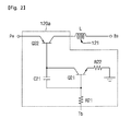
- FIG. 2 illustrates a circuit diagram of a current amplifying unit and noise filter of a battery pack having boosting charge function according to an embodiment.
- a current amplifying unit 120a includes a first resistor R21, a first transistor Q21, a first capacitor C21, a second resistor R22, and a second transistor Q22.
- the first resistor R21 is connected between the first transistor Q21 and the control unit 170. That is, a first electrode of the first resistor R21 is connected to the control unit 170, and a second electrode of the first resistor R21 is connected to the first transistor Q21. Accordingly, the control signal Tb of the control unit 170 is applied to the first transistor Q21 through the first resistor R21.
- the first transistor Q21 includes a control electrode, a first electrode, and a second electrode.
- a second electrode of the first resistor R21 is connected to the control electrode of the first transistor Q21.
- the first capacitor C21 and the second transistor Q22 are connected to the first electrode of the first transistor Q21.
- the second resistor R22 is connected to the second electrode of the first transistor Q21.
- the first transistor Q21 may be an NPN power transistor.
- the first capacitor C21 is connected between the first electrode and control electrode of the first transistor Q21. That is, a first electrode of the first capacitor C21 is connected to the first electrode of the first transistor Q21, and a second electrode of the capacitor C21 is connected to the control electrode of the first transistor Q21.
- the second resistor R22 is connected between the second electrode of the first transistor Q21 and a ground terminal. That is, a first electrode of the second resistor R22 is connected to the second electrode of the first transistor Q21, and a second electrode of the second resistor R22 is grounded.
- the second transistor Q22 includes a control electrode, a first electrode, and a second electrode.
- the first electrode of the first capacitor C21 and the first electrode of the first transistor Q21 are connected to the control electrode of the second transistor Q22.
- the pack positive terminal P+ is connected to the first electrode of the second transistor Q22. Accordingly, a current from the charger 190 is supplied to the first electrode of the second transistor Q22.
- the cell positive terminal B+ is electrically connected to the second electrode of the second transistor Q22. Therefore, the battery cell 110 receives an amplified current through the second electrode of the second transistor Q22.
- the second transistor Q22 may be a PNP power transistor.
- the noise filter 121 may be substantially connected between the second electrode of the second transistor Q22 and the cell positive terminal B+.
- the noise filter 121 may be an inductor L.
- the current amplifying unit 120a may be a cascaded pair of power transistors that boost a current from the charger 190 and supply the boosted current to the battery cell 110.
- control unit 170 provides a control signal Tb of about 0.7 V or higher to the first resistor R21. Then, a current Ibe (current from base to emitter) flows through the first resistor R21, the control electrode and second electrode of the first transistor Q21 and the second resistor R22.
- a current Ibe current from base to emitter
- a gain is about 50 times. That is, a current Ice that flows from the first electrode of the first transistor Q21 to the second electrode of the first transistor Q21 may be about 50 times higher than the current Ibe.
- the current Ice that flows through from the first and second electrodes of the first transistor Q21 is supplied from the control electrode of the second transistor Q22. Also, a current that flows through the first and second electrodes of the second transistor Q22 is amplified by about 50 times by a current that flows through the control electrode of the second transistor Q22.
- a charge current that is supplied through the pack positive terminal P+ is amplified by the second transistor Q22 and is supplied to the cell positive terminal B+.
- a current of about 500 mA that is supplied from the charger 190 may be amplified to a current of about 1 to 1.5 A and be supplied to the battery cell 110.
- the gain of the first transistor Q21 and the gain of the second transistor Q22 are appropriately controlled, and thus, as described above, a current supplied from the charger 190 may be amplified by about 110 to 130 % and be supplied to the battery cell 110.
- an electrical noise that may occur in an amplified current is filtered by the noise filter 121 that is serially connected to the second transistor Q22 and the cell positive terminal B+.
- the current amplifying unit 120a is suitable when the charger 190 is a portable phone charger or a computer USB power source. This is because a voltage supplied through the pack positive terminal P+ by the current amplifying unit 120a is similar to a voltage that is supplied to the cell positive terminal B+ by the current amplifying unit 120a and a current is amplified.
- FIG. 3 illustrates a circuit diagram of a current amplifying unit and noise filter of a battery pack having boosting charge function according to another embodiment.
- a current amplifying unit 120b includes a first transistor Q31, a voltage regulator VR, a second transistor Q32, and a diode D31.
- the first transistor Q31 includes a control electrode, a first electrode, and a second electrode.
- the control electrode of the first transistor Q31 is connected to the control unit 170, and thus it receives the control signal Tb from the control unit 170.
- the first electrode of the first transistor Q31 is connected to the pack positive terminal P+, and the second electrode of the first transistor Q31 is connected to the voltage regulator VR and the second transistor Q32.
- the voltage regulator VR includes an input terminal I, an output terminal O, and a ground terminal G.
- the input terminal I of the voltage regulator VR is connected to the second electrode of the first transistor Q31 and to the second transistor Q32.
- the output terminal O of the voltage regulator VR is connected to the second transistor Q32.
- the ground terminal G of the voltage regulator VR is connected to the diode D31.
- the second transistor Q32 includes a control electrode, a first electrode, and a second electrode.
- the control electrode of the second transistor Q32 is connected to the output terminal O of the voltage regulator VR.
- the first electrode of the second transistor Q32 is connected to the second electrode of the first transistor Q31 and the input terminal I of the voltage regulator VR.
- the second electrode of the second transistor Q32 is connected to the cell positive terminal B+.
- the diode D31 is connected between the ground terminal G of the voltage regulator VR and a ground terminal. That is, a first electrode of the diode D31 is connected to the ground terminal G of the voltage regulator VR, and a second terminal of the diode D31 is connected to the ground terminal.
- the diode D31 compensates voltage drop between the control electrode and second electrode of the second transistor Q32.
- the noise filter 121 may be substantially and electrically connected between the second electrode of the second transistor Q32 and the cell positive terminal B+.
- the noise filter 121 may be an inductor L.
- the control unit 170 provides the control signal Tb to the control electrode of the first transistor Q31, the first transistor Q31 is turned on, and thus the current amplifying unit 120b operates. In this way, when the first transistor Q31 is turned on, a power source from the pack positive terminal P+ is supplied to the input terminal I of the voltage regulator VR and the first electrode of the second transistor Q32.
- a voltage between the ground terminal G and output terminal O of the voltage regulator VR is constant. Accordingly, a current supplied to the cell positive terminal B+ through the second electrode of the second transistor Q32 is amplified. That is, a current from the pack positive terminal P+ is amplified and is supplied to the cell positive terminal B+. As another example, a current from the charger 190 is amplified and is supplied to the battery cell 110.
- the current amplifying unit 120b is very suitable when the charger 190 is a cigar jack power source for a vehicle. This is because a voltage supplied through the pack positive terminal P+ is higher than a voltage supplied to the cell positive terminal B+, or is because a voltage inputted to the input terminal of the voltage regulator VR is higher than a voltage that is outputted through the output terminal of the voltage regulator VR.
- FIG. 4 illustrates a circuit diagram of a current amplifying unit and noise filter of a battery pack having boosting charge function according to another embodiment.
- a current amplifying unit 120c includes a first transistor Q41, a second transistor Q42, a resistor R41, and a voltage regulator VR.
- the first transistor Q41 includes a control electrode, a first electrode, and a second electrode.
- the control electrode of the first transistor Q41 is connected to the control unit 170, and thus it receives the control signal Tb from the control unit 170.
- the first electrode of the first transistor Q41 is connected to the pack positive terminal P+, and the second electrode of the first transistor Q41 is connected to the second transistor Q42 and the resistor R41.
- the second transistor Q42 includes a control electrode, a first electrode, and a second electrode.
- the control electrode of the second transistor Q42 is connected to the resistor R41 and the voltage regulator VR.
- the first electrode of the second transistor Q42 is connected to the second electrode of the first transistor Q41 and the resistor R41.
- the second electrode of the second transistor Q42 is connected to the voltage regulator VR and the cell positive terminal B+.
- the resistor R41 is connected between the first transistor Q41, the second transistor Q42 and the voltage regulator VR. That is, a first electrode of the resistor R41 is connected to the second electrode of the first transistor Q41 and the first electrode of the second transistor Q42. A second electrode of the resistor R41 is connected to the control electrode of the second transistor Q42 and an input terminal I of the voltage regulator VR.
- the voltage regulator VR includes an input terminal I, an output terminal O, and a ground terminal G.
- the input terminal I of the voltage regulator VR is connected to a second electrode of the resistor R41 and the second electrode of the second transistor Q42.
- the output terminal O of the voltage regulator VR is connected to the second electrode of the second transistor Q42 and the cell positive terminal B+.
- the ground terminal G of the voltage regulator VR is grounded.
- the noise filter 121 may be substantially and electrically connected between the second electrode of the second transistor Q42 and the cell positive terminal B+.
- the noise filter 121 may be an inductor L.
- the current amplifying unit 120b of FIG. 3 uses an NPN type of second transistor Q32, the output voltage of the voltage regulator VR is become lower than the original output voltage.
- the current amplifying unit 120c of FIG. 4 uses a PNP type of second transistor Q42 (i.e., power transistor), the original output voltage of the voltage regulator VR may be maintained.
- the current amplifying unit 120c is suitable when the charger 190 is a cigar jack power source for a vehicle. This is because a voltage supplied through the pack positive terminal P+ is higher than a voltage supplied to the cell positive terminal B+.
- FIG. 5 illustrates a circuit diagram of a pre-charge unit of a battery pack having boosting charge function according to an embodiment.
- the pre-charge unit 130 includes a resistor R1 and a transistor M2.
- a first electrode of the resistor R1 is connected to the pack positive terminal P+, and a second electrode of the resistor R1 is connected to the transistor M2.
- the transistor M1 includes a control electrode, a first electrode, and a second electrode.
- the control electrode receives the control signal M1g from the control unit 170.
- the first electrode of the transistor M2 is connected to a second electrode of the resistor R1.
- the second electrode of the transistor M2 is connected to the cell positive terminal B+.
- the transistor M1 may be a P-channel MOSFET having a body diode.
- the pre-charge unit 130 When the control unit 170 applies the control signal M1g to the control electrode of the transistor M1, the pre-charge unit 130 operates. At this point, since a certain voltage is applied to the resistor R1, a voltage supplied from the pack positive terminal P+ decreases in proportion to the applied voltage and is supplied to the cell positive terminal B+. That is, a voltage supplied from the charger 190 decreases and is supplied to the battery cell 110.
- the pre-charge unit 130 may supply about 10 to 40 % of the voltage supplied from the charger 190 to the battery cell 110.
- FIG. 6 illustrates a circuit diagram of a pulse charge unit of a battery pack having boosting charge function according to an embodiment.
- the pulse charge unit 140 includes a transistor M1.
- the transistor M1 includes a control electrode, a first electrode, and a second electrode.
- the control electrode receives the control signal M2g from the control unit 170.
- the first electrode of the transistor M1 is connected to the pack positive terminal P+.
- the second electrode of the transistor M1 is connected to the cell positive terminal B+.
- the transistor M2 may be a P-channel MOSFET having a body diode.
- the pulse charge unit 140 When the control unit 170 applies the control signal M2g to the control electrode of the transistor M2, the pulse charge unit 140 operates.
- the control signal M2g is supplied at intervals of about 3 ms to 3 s, a voltage supplied from the pack positive terminal P+ is converted into a pulse-type voltage and is supplied to the cell positive electrode B+. That is, a voltage supplied from the charger 190 is converted into a pulse-type voltage and is supplied to the battery cell 110.
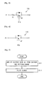
- FIG. 7 illustrates a schematic flowchart of a boosting charge method according to an embodiment.
- a boosting charge method includes: a current amplification charge operation S 11 that amplifies a current supplied from a charger to perform charge; and a pulse charge operation S 12 that converts a voltage supplied from the charger into a pulse type to perform charge.
- the charger may be a portable phone charger, a computer USB power source or a cigar jack of a vehicle in accordance with an international standard.
- the current amplification charge operation S11 amplifies the current supplied from the charger by about 110 to 130 % or about 125 % and supplies the amplified current to a battery cell, thereby allowing the battery cell to be charged by the amplified current.
- the pulse charge operation S12 converts a Direct Current (DC) voltage supplied from the charger into a pulse-type voltage and supplies the pulse-type voltage to the battery cell, thereby allowing the battery cell to be charged with the pulse-type voltage.
- DC Direct Current
- FIG. 8 illustrates a schematic flowchart of a boosting charge method according to another embodiment.
- a boosting charge method includes: determining whether a battery cell voltage exceeds a first voltage in operation S21; determining whether a battery cell voltage exceeds a second voltage in operation S22; amplifying a current supplied from a charger to perform charge in operation S23; determining whether the battery cell voltage exceeds a second voltage in operation S24; and performing pulse charge in operation S25.
- operation S21 determines whether a battery cell voltage exceeds a first voltage. That is, whether the voltage of the battery cell exceeds about 3.0 V is determined.
- FIG. 9 illustrates a flowchart of a boosting charge method according to an embodiment.
- FIG. 10 is a graph showing relationships between a current, a cell voltage, a capacity and a charge time during boosting charge according to an embodiment.
- a boosting charge method according to an embodiment will be described below with reference to FIGS. 1 , 9 and 10 .
- a boosting charge method according to an embodiment is controlled by the control unit 170 of FIG. 1 .
- a boosting charge method includes: determining whether a voltage of a battery cell exceeds a first voltage in operation S31; determining whether the voltage of the battery cell exceeds a second voltage in operation S32; amplifying a current to perform charge in operation S33; determining whether the voltage of the battery cell exceeds a second voltage in operation S35; and performing pulse charge in operation S36.
- the boosting charge method may further include determining whether the temperature of the battery cell exceeds a reference temperature in operation S34.
- the boosting charge method may further include: performing pre-charge in operation S37; and determining whether the voltage of the battery cell exceeds the first voltage in operation S38.
- the control unit 170 determines whether the voltage of the battery cell 110 exceeds the first voltage with the voltage sensing unit 150.
- the first voltage may be set as about 3.0 V, but it is not limited thereto.
- control unit 170 When the voltage of the battery cell 110 exceeds the first voltage as the determined result, the control unit 170 performs operation S32. When the voltage of the battery cell 110 is lower than the first voltage as the determined result, the control unit 170 performs operation S37. Operation S37 will be again described below.
- the control unit 170 determines whether the voltage of the battery cell 110 exceeds the second voltage with the voltage sensing unit 150.
- the second voltage may be set as about 4.1 to 4.25 V or about 4.2 V, but it is not limited thereto.
- control unit 170 When the voltage of the battery cell 110 exceeds the second voltage as the determined result, the control unit 170 performs operation S36. When the voltage of the battery cell 110 is lower than the second voltage as the determined result, the control unit 170 performs operation S33. Operation S36 will be again described below.
- the control unit 170 provides the control signal Tb to the current amplifying unit 120 and thus allows the current amplifying unit 120 to operate.
- the current amplifying unit 120 amplifies a current supplied from the pack positive terminal P+ by about 110 to 130 % or about 125 % and supplies the amplified current to the cell positive terminal B+. That is, the current amplifying unit 120 amplifies the original charge current supplied from the charger 190 by about 110 to 130 % or about 125 % and supplies the amplified current to the battery cell 110.
- the current amplifying rate is lower than about 110 %, the charge of the battery cell 110 is performed for a relatively long time. Moreover, when the current amplifying rate exceeds about 130 %, the battery cell 110 is quickly deteriorated, and thus the life of the battery cell 110 may be shortened.
- a current supplied from the charger 190 is about 1 A
- a current is amplified to about 1.1 to 1.3 A by the current amplifying unit 120.
- a charge time by an amplified current varies with the capacity of the battery cell 110
- the battery cell 110 used for portable phones expends about one hour, and at this point, the battery cell 110 is substantially charged to a capacity of about 93 to 96 %.
- the battery cell 110 is charged to a capacity of about 83 to 86 %. According to an embodiment, therefore, a capacity of about 10 % is further charged relative to the existing time.
- a current amplified by the current amplifying unit 120 is slowly lowered with the elapse of time. This occurs because the voltage of the battery cell 110 increases.
- an amplified current may always consistently be outputted irrespective of the elapse of time.
- control unit 170 determines whether the temperature of the battery cell 110 exceeds about 55 to 60°C with the temperature sensing unit 160. When the temperature of the battery cell 110 exceeds about 55 to 60°C as the determined result, the control unit 170 stops charge for the stability of the battery cell 110. When the temperature of the battery cell 110 is equal to or lower than about 55 to 60°C as the determined result, the control unit 170 performs operation S35.
- Operation S34 may be performed in any stage of the boosting charge method according to an embodiment, as described herein, and is not necessarily performed between operation S33 and operation S35. That is, in an embodiment, once the temperature of the battery cell 110 exceeds about 55 to 60°C, the control unit 170 stops the operations of the current amplifying unit 120, pre-charge unit 130 and pulse charge unit 140 in all operations, thereby securing the stability of the battery cell 110. When the temperature of the battery cell 110 exceeds about 55 to 60°C, the control unit 170 lowers a current amplifying rate, decreases a pre-charge voltage or narrows a pulse charge width without the stop of charge according to a more complicated algorithm, thereby securing the stability of the battery cell 110.
- the control unit 170 determines whether the voltage of the battery cell 110 exceeds the second voltage with the voltage sensing unit 150.
- the second voltage may be set as about 4.1 to 4.25 V or about 4.2 V, but it is not limited thereto.
- the control unit 170 When the voltage of the battery cell 110 exceeds the second voltage as the determined result, the control unit 170 performs operation S36. When the voltage of the battery cell 110 is equal to or lower than the second voltage as the determined result, the control unit 170 performs operation S33. That is, the control unit 170 amplifies a current from the charger 190 to charge the battery cell 110 until the voltage of the battery cell 110 reaches the second voltage. Herein, it has been described above that about one hour is taken until the voltage of the battery cell 110 reaches the second voltage.
- the control unit 170 allows the operation of the current amplifying unit 120 to be stopped.
- the control unit 170 allows the pulse charge unit 140 to operate.
- the pulse charge unit 140 converts a voltage from the pack positive terminal P+ into a pulse-type voltage and supplies the pulse-type voltage to the cell positive terminal B+. That is, the pulse charge unit 140 converts a DC voltage from the charger 190 into a pulse-type voltage and supplies the pulse-type voltage to the battery cell 110.
- the pulse charge unit 140 converts a voltage from the charger 190 into a pulse-type voltage having intervals of about 3 ms to 3 s and supplies the pulse-type voltage to the battery cell 110. For example, as shown in FIG.
- the pulse charge unit 140 converts a voltage from the charger 190 into a pulse-type voltage and supplies the pulse-type voltage to the battery cell 110 for about 3 ms to 3 s, and then the pulse charge unit 140 does not supply the voltage from the charger 190 to the battery cell 110 for about 3 ms to 3 s.
- the pulse charge unit 140 repeats such an operation for about 0.4 to 0.6 hours and stops the operation. That is, the control unit 170 stops the output of the control signal M2g after the time, and thus the operation of the pulse charge unit 140 is stopped.
- the boosting charge method When the voltage of the battery cell 110 is determined as lower than the first voltage in operation S31 where the control unit 170 determines whether the voltage of the battery cell 110 exceeds the first voltage, the boosting charge method according to an embodiment performs pre-charge operation S37.
- the control unit 170 allows the pre-charge 130 to operate.
- the pre-charge unit 130 decreases a voltage supplied from the pack positive terminal P+ and supply about 10 to 40 % of the voltage from the pack positive terminal P+ to the cell positive terminal B+. That is, the pre-charge unit 130 decreases a voltage supplied from the charger 190 and supply about 10 to 40 % of the voltage from the charger 190 to the battery cell 110.
- the pre-charge voltage is lower than about 10 %, pre-charge is performed for a very long time. Moreover, when the pre-charge voltage exceeds about 40 %, the battery cell 110 may be deteriorated.
- the control unit 170 pre-charges the battery cell 110 for a certain time, and performs operation S38 that determines whether the voltage of the battery cell 110 exceeds the first voltage through the voltage sensing unit 150. When the voltage of the battery cell 110 exceeds about 3.0 V as the determined result, the control unit 170 performs operation S32. However, when the voltage of the battery cell 110 still is equal to or lower than about 3.0 V as the determined result, the control unit 170 determines that a slight short occurs in the battery cell 110 or the battery cell 110 has been completely discharged, and stops the charge of the battery cell 110. Furthermore, the control unit 170 stops the output of the control signal M1g in the end of pre-charge operation S37, thereby allowing the operation of the pre-charge unit 130 to be stopped.
Abstract
Description
- Embodiments relate to a battery pack having boosting charge function and a method thereof.
- Generally, a battery that cannot again be used once discharged is called a primary battery, and a battery that may be continuously used through charge when discharged is called a secondary battery.
- Recently, with the increase in the supply of portable devices such as feature phones, smart phones, Personal Digital Assistant (PDA) phones and digital cameras, the demand of secondary batteries is increasing rapidly. Secondary batteries used for the portable devices require high-stability and thin characteristics for convenient carrying and charging characteristic that remain stable in situations where the secondary batteries are fully charged early in the charging cycle time and thus are fully charged during the remainder of the charging cycle.
- As a method for charging secondary batteries used for the portable devices, a Constant Current mode-Constant Voltage mode charge method (CC-CV charge method) is generally used. In charging the secondary batteries, the CC-CV charge method is one that performs charge with a certain constant current and thereafter charges the secondary battery with a constant voltage when a voltage close to a full-charge potential is reached.
- Research on various charge methods that may perform more accurate full charge and perform charge at a faster charge speed than the CC-CV charge method has been conducted.
- Furthermore, as the supply of various portable devices having a large consumption power increases rapidly, interest in batteries is increasing. Accordingly, a charge method and a charge apparatus are required which are more stable and may perform full charge within an early time.
- An aspect of the present invention provides a battery pack having boosting charge function and a method thereof.
- According to an aspect of the present invention there is provided a battery pack that comprises a battery cell, a terminal for connection to a charging device and a current amplifying unit connected between the terminal and the battery cell for amplifying a first current received at the terminal.
- The battery pack may be adapted such that the current amplifying unit outputs a second current that is higher than the first current when the voltage of the battery cell falls within a range of values extending from a relatively lower first voltage to a relatively higher second voltage.
- The battery pack may further comprising a pulse charge unit connected between the terminal and the battery cell for converting a voltage at the terminal into a pulsed voltage.
- The battery pack may further be adapted such that the pulse charge unit outputs the said pulsed voltage when the voltage of the battery cell exceeds the said second voltage.
- The battery pack may further comprise a pre-charge unit connected between the terminal and the battery cell for converting a voltage received at the terminal into a lower voltage.
- The battery pack may further be adapted such that the pre-charge unit outputs the said lower voltage when the voltage of the battery is below the said first voltage.
- The battery pack may further comprise a control unit for controlling the operation of the current amplifying unit.
- The control unit may also be adapted to control the operation of the pulse unit and the pre-charge unit.
- The battery pack may further comprise a voltage sensing unit for sensing the voltage of the battery cell.
- The voltage sensing unit may be adapted to supply a voltage sensing signal to the control unit.
- The battery pack may further comprise a temperature sensing unit for sensing a temperature of the said battery cell.
- The current amplifying unit may further comprise a first transistor, a capacitor and a second transistor. In this embodiment the control electrode of the first transistor is coupled to the control unit, a first electrode of the first transistor is coupled to a control electrode of the second transistor, a second electrode of the first transistor is coupled to ground, a first electrode of the second transistor is coupled to the terminal, a second electrode of the second transistor is coupled to the battery cell and the capacitor is coupled between the control electrode and the first electrode of the first transistor.
- In another embodiment the current amplifying unit comprises a first transistor, a second transistor and a voltage regulator. In this embodiment a control electrode of the first transistor is coupled to the control unit, a first electrode of the first transistor is coupled to the terminal, a second electrode of the first transistor is coupled to a first electrode of the second transistor and an input terminal of the voltage regulator, a second electrode of the second transistor is coupled to the battery cell and a control electrode of the second transistor is coupled to the input terminal or an output terminal of the voltage regulator.
- According to another aspect of the present invention there is provided a method of charging a battery pack. The method comprises using a current amplifying unit of the battery pack to amplify a current received at a terminal of the battery pack when the voltage of a battery cell of the battery pack falls within a range of values extending from a relatively lower first voltage to a relatively higher second voltage.
- The method may further comprise converting a voltage at the said terminal into a pulsed voltage using a pulse charge unit of the battery pack when the voltage of the battery cell exceeds the said second voltage and/or converting a voltage received at the terminal into a lower voltage using a pre-charge unit of the battery pack when the voltage of the battery cell is below the said first voltage.
- A battery pack having boosting charge function according to an embodiment amplifies a charge current that is supplied from the existing portable phone charger, a computer USB power source or the cigar jack power source of a vehicle (hereinafter referred to as a charger) and performs charge by itself.
- Moreover, a booting charge method according to an embodiment includes amplifying a charge current which is supplied by a charger to charge a battery cell; and charging the battery cell with a constant voltage. Herein, the charging of the battery cell may be substantially performed in a pulse charge scheme.
- The charging of the battery cell is continuously performed to the full charge voltage of the battery cell. The full charge voltage may be set to about 4.1 to 4.25 V or about 4.2 V. During the charging of the battery cell, the amplified current may be substantially and incrementally reduced with the elapse of time. The amplified current may be set to about 110 to 130 % or 125 % of the charge current that is supplied by the charger.
- The boosting charge method according to an embodiment includes determining whether a battery cell voltage exceeds a first voltage; amplifying a charge current from a charger to perform charge; determining whether the battery cell voltage exceeds a second voltage; and performing pulse charge.
- When the battery cell voltage does not exceed the first voltage, the battery cell is precharged with a lower voltage than the first voltage.
- The battery pack having boosting charge function according to an embodiment may further include a current amplifying unit amplifying a charge current which is supplied from a charger. Herein, a noise filter may be connected to an output terminal of the current amplifying unit. The battery pack having boosting charge function according to an embodiment may further include a control unit sensing a voltage from the battery cell to control the current amplifying unit.
- A battery pack and method thereof according to embodiments considerably shorten the charge time of the battery pack by using a current amplifying-pulse charge scheme. As an example, the existing charge time takes about 3 to 4 hours, but according to embodiments, a charge time takes about 1.5 hours or less.
- The battery pack and method thereof according to embodiments supply a small amount of current to the battery cell to allow the battery cell to be charged in an initial charge, and sense the voltage of the battery cell. When the voltage of the battery cell increases, the battery pack and method thereof determine that there is no error, and perform charge in the current amplifying-pulse charge scheme. When the voltage of the battery cell does not increase, the battery pack and method thereof determine that a slight short occurs in the battery cell or the battery cell has been completely discharged, and stop charge, thereby improving the stability of the battery pack.
- Moreover, the battery pack and method thereof according to embodiments sense the temperature of the battery cell while the battery pack is being charged, and stop charge or decreases the charge current when the temperature of the battery cell exceeds the reference temperature, thereby enhancing the stability of the battery pack.
-
FIG. 1 illustrates a block diagram of a battery pack having boosting charge function according to an embodiment; -
FIG. 2 illustrates a circuit diagram of a current amplifying unit and noise filter of a battery pack having boosting charge function according to an embodiment; -
FIG. 3 illustrates a circuit diagram of a current amplifying unit and noise filter of a battery pack having boosting charge function according to another embodiment; -
FIG. 4 illustrates a circuit diagram of a current amplifying unit and noise filter of a battery pack having boosting charge function according to another embodiment; -
FIG. 5 illustrates a circuit diagram of a pre-charge unit of a battery pack having boosting charge function according to an embodiment; -
FIG. 6 illustrates a circuit diagram of a pulse charge unit of a battery pack having boosting charge function according to an embodiment; -
FIG. 7 illustrates a schematic flowchart of a boosting charge method according to an embodiment; -
FIG. 8 illustrates a schematic flowchart of a boosting charge method according to another embodiment; -
FIG. 9 illustrates a flowchart of a boosting charge method according to an embodiment; and -
FIG. 10 is a graph showing relationships between a current, a cell voltage, a capacity and a charge time during boosting charge according to an embodiment. - Example embodiments will now be described more fully hereinafter with reference to the accompanying drawings; however, they may be embodied in different forms and should not be construed as limited to the embodiments set forth herein. Rather, these embodiments are provided so that this disclosure will be thorough and complete, and will fully convey the scope of the disclosure to those skilled in the art.
- In this disclosure below, like reference numerals are used for referring to the same or similar elements or operations throughout. Moreover, when one part (or element, device, etc.) is referred to as being 'connected' to another part (or element, device, etc.), it should be understood that the former can be 'directly connected' to the latter, or 'electrically connected' to the latter via an intervening part (or element, device, etc.).
-
FIG. 1 illustrates a block diagram of a battery pack having boosting charge function according to an embodiment. - Referring to
FIG. 1 , abattery pack 100 having boosting charge function according to an embodiment includes at least onebattery cell 110, a current amplifyingunit 120, apre-charge unit 130, and apulse charge unit 140. The current amplifyingunit 120 is connected between thebattery cell 110 and acharger 190 and amplifies a current from thecharger 190 to quickly charge thebattery cell 110. Thepre-charge unit 130 is connected between thebattery cell 110 and thecharger 190 and decreases a voltage from thecharger 190 to pre-charge thebattery cell 110. Thepulse chare unit 140 is connected between thebattery cell 110 and thecharger 190 and converts a voltage from thecharger 190 into a pulse-type voltage to pulse-charge thebattery cell 110. - In addition, the
battery pack 100 according to an embodiment includes avoltage sensing unit 150 and atemperature sensing unit 160. Moreover, thebattery pack 100 further includes acontrol unit 170 that receives the signal of thevoltage sensing unit 150 and the signal of thetemperature sensing unit 160 to control thecurrent amplifying unit 120, thepre-charge unit 130 and thepulse charge unit 140 according to a predetermined algorithm. Furthermore, thebattery pack 100 includes a pack positive terminal P+ and a pack negative terminal P-, and the pack positive terminal P+ and the pack negative terminal P- are connected to theexternal charger 190 or an external load (not shown). - The
battery cell 110 may be a secondary battery that has a cell positive terminal B+ and a cell negative terminal B- and may be recharged. As an example, thebattery cell 110 may be any one that is selected from among a lithium ion battery, a lithium polymer battery, a lithium ion polymer battery and equivalent materials thereof, but an embodiment is not limited thereto. Also, thebattery cell 110 may be any one that is selected from among a cylinder type battery, a prismatic type battery, a pouch type battery and equivalent materials thereof, but an embodiment is not limited thereto. - The
current amplifying unit 120 is connected between the pack positive terminal P+ and the cell positive terminal B+. Thecurrent amplifying unit 120 operates according to a control signal Tb of thecontrol unit 170, and amplifies a current supplied from thecharger 190 to supply the amplified current to thebattery cell 110. Herein, when the voltage of thebattery cell 110 sensed by thevoltage sensing unit 150, for example, is determined as about 3.0 to 4.2 V, thecontrol unit 170 fundamentally outputs the control signal Tb for operating thecurrent amplifying unit 120 to thecurrent amplifying unit 120. Furthermore, thecurrent amplifying unit 120 does not amplify a voltage supplied from thecharger 190 but amplifies only a current to supply the amplified current to thebattery cell 110. Thecurrent amplifying unit 120, for example, amplifies a current supplied from thecharger 190 by about 110 to 130 % or about 125 % and supplies the amplified current to thebattery cell 110. When the current amplifying rate is lower than about 110 %, the charge time of thebattery cell 110 is not greatly shortened relative to the existing one. Herein, the full charge time of thebattery cell 110 typically takes about 3 to 4 hours. Moreover, when the current amplifying rate exceeds about 130 %, thebattery cell 110 may be deteriorated. That is, the life of thebattery cell 110 may be shortened. Thenoise filter 121 may further be connected between thecurrent amplifying unit 120 and thebattery cell 110. Thenoise filter 121 filters all kinds of electrical noises that are generated from thecurrent amplifying unit 120. - The
pre-charge unit 130 is connected between the pack positive terminal P+ and the cell positive terminal B+. Thepre-charge unit 130 operates according to a control signal M1g of thecontrol unit 170, and decreases a voltage supplied from thecharger 190 to supply the decreased voltage to thebattery cell 110. Herein, when the voltage of thebattery cell 110 sensed by thevoltage sensing unit 150, for example, is determined as lower than about 3.0V, thecontrol unit 170 fundamentally outputs the control signal M1g for operating thepre-charge unit 130 to thepre-charge unit 130. Thepre-charge unit 130, for example, supplies about 10 to 40 % of the voltage supplied from thecharger 190 to thebattery cell 110. For example, when the voltage supplied from thecharger 190 is about 4.2V, thepre-charge unit 130 supplies about 4.2*(1/10) V through 4.2*(4/10) V to thebattery cell 110. When the pre-charge voltage is lower than about 10 %, pre-charge is performed for a very long time. Also, when the pre-charge voltage exceeds about 40 %, thebattery cell 110 may be deteriorated. - After a predetermined time has elapsed during pre-charging, the
control unit 170 determines if a short circuit has occured in thebattery cell 110 or if thebattery cell 110 has been completely discharged. If the voltage of thebattery cell 110 does not exceed about 3.0 V after the predetermined time thecontrol unit 170 stops the charge of thebattery cell 110. - The
pulse charge unit 140 is connected between the pack positive terminal P+ and the cell positive terminal B+. Thepulse charge unit 140 operates according to a control signal M2g of thecontrol unit 170, and converts a voltage supplied from thecharger 190 into a pulse-type voltage to supply the pulse-type voltage to thebattery cell 110. Herein, when the voltage of thebattery cell 110 sensed by thevoltage sensing unit 150, for example, is determined as exceeding about 4.1 to 4.25 V or about 4.2 V, thecontrol unit 170 outputs the control signal M2g for operating thepulse charge unit 140. When the voltage is lower than about 4.1 V, the full charge of thebattery cell 110 is performed for a very long time. Also, the when voltage exceeds about 4.25 V, thebattery cell 110 may be deteriorated. Here, thecurrent amplifying unit 120 operates when the voltage of thebattery cell 110 is about 3.0 to 4.2 V, while thepulse charge unit 140 operates when the voltage of thebattery cell 110 is about 4.1 to 4.25 V. Therefore, some range of the voltages for thebattery cell 110 seems to overlap with each other. However, when actually manufacturing the battery pack, the overlapping voltage range is eliminated. For example, thecurrent amplifying unit 120 operates when the voltage of thebattery cell 110 is about 3.0 to 4.1 V, while thepulse charge unit 140 operates when the voltage of thebattery cell 110 exceeds about 4.1 V. For other example, thecurrent amplifying unit 120 operates when the voltage of thebattery cell 110 is about 3.0 to 4.2 V, while thepulse charge unit 140 operates when the voltage of thebattery cell 110 exceeds about 4.2 V. The range of the voltage for thebattery cell 110 may vary according to the capacity or usage of the battery pack, but it is not limited thereto. - The
voltage sensing unit 150 is connected to thebattery cell 110 in parallel and senses the voltage of thebattery cell 110. Furthermore, thevoltage sensing unit 150 converts the sensed analog voltage value of thebattery cell 110 into a digital voltage value and provides the digital voltage value to thecontrol unit 170. - The
temperature sensing unit 160 is pressed against thebattery cell 110 or is disposed in a periphery and senses the temperature of thebattery cell 110. Thetemperature sensing unit 160 converts the sensed analog temperature value of thebattery cell 110 into a digital temperature value and provides the digital temperature value to thecontrol unit 170. - The
control unit 170 receives the signal of thevoltage sensing unit 150 and the signal of thetemperature sensing unit 160 and outputs respective control signals to thecurrent amplifying unit 120, thepre-charge unit 130 and thepulse charge unit 140 according to a predetermined algorithm. For example, when the voltage of thebattery cell 110 sensed by thevoltage sensing unit 150 is about 3.0 to 4.2 V, by outputting the control signal Tb to thecurrent amplifying unit 120, thecontrol unit 170 allows thecurrent amplifying unit 120 to amplify a current from thecharger 190 and supply the amplified current to thebattery cell 110. When the voltage of thebattery cell 110 sensed by thevoltage sensing unit 150 is lower than about 3.0 V, by outputting the control signal M1g to thepre-charge unit 130, thecontrol unit 170 allows thepre-charge unit 130 to decreases a voltage from thecharger 190 and supply the decreased voltage to thebattery cell 110. When the voltage of thebattery cell 110 sensed by thevoltage sensing unit 150 exceeds about 4.1 to 4.25 V or 4.2V, by outputting the control signal M2g to thepulse charge unit 140, thecontrol unit 170 allows thepulse charge unit 140 to convert a voltage from thecharger 190 into a pulse-type voltage and supply the pulse-type voltage to thebattery cell 110. Moreover, when the temperature of thebattery cell 110 sensed by thetemperature sensing unit 160 exceeds about 55 to 60°C, thecontrol unit 170 stops the charge of thebattery cell 110. That is, thecontrol unit 170 stops the operation of thecurrent amplifying unit 120,pre-charge unit 130 orpulse charge unit 140, and thus the temperature of thebattery cell 110 does not further increase. Naturally, as the temperature of thebattery cell 110 increases, thecontrol unit 170 decreases a current amplifying rate, a pre-charge voltage or a pulse width, thereby suppressing the temperature increase of thebattery cell 110. - The
charger 190 is connected between the pack positive terminal P+ and the pack negative terminal P- in parallel and supplies a charge current and a charge voltage to thebattery cell 110. Thecharger 190, for example, may be a portable phone charger 190 (standard charger) for supplying an output voltage of about 4.2 V and a current of about 600 to 800 mA, or a computer USB power source having an output voltage of about 5 V and a current of about 500 mA. Herein, the output voltages and currents of theportable phone charger 190 and computer USB power source are standardized internationally. Furthermore, thecharger 190 may be a cigar jack power source of a vehicle that has an output voltage of about 12 V and a current of about 500 mA. -
FIG. 2 illustrates a circuit diagram of a current amplifying unit and noise filter of a battery pack having boosting charge function according to an embodiment. - Referring to
FIG. 2 , acurrent amplifying unit 120a includes a first resistor R21, a first transistor Q21, a first capacitor C21, a second resistor R22, and a second transistor Q22. - The first resistor R21 is connected between the first transistor Q21 and the
control unit 170. That is, a first electrode of the first resistor R21 is connected to thecontrol unit 170, and a second electrode of the first resistor R21 is connected to the first transistor Q21. Accordingly, the control signal Tb of thecontrol unit 170 is applied to the first transistor Q21 through the first resistor R21. - The first transistor Q21 includes a control electrode, a first electrode, and a second electrode. A second electrode of the first resistor R21 is connected to the control electrode of the first transistor Q21. The first capacitor C21 and the second transistor Q22 are connected to the first electrode of the first transistor Q21. The second resistor R22 is connected to the second electrode of the first transistor Q21. Herein, the first transistor Q21 may be an NPN power transistor.
- The first capacitor C21 is connected between the first electrode and control electrode of the first transistor Q21. That is, a first electrode of the first capacitor C21 is connected to the first electrode of the first transistor Q21, and a second electrode of the capacitor C21 is connected to the control electrode of the first transistor Q21.
- The second resistor R22 is connected between the second electrode of the first transistor Q21 and a ground terminal. That is, a first electrode of the second resistor R22 is connected to the second electrode of the first transistor Q21, and a second electrode of the second resistor R22 is grounded.
- The second transistor Q22 includes a control electrode, a first electrode, and a second electrode. The first electrode of the first capacitor C21 and the first electrode of the first transistor Q21 are connected to the control electrode of the second transistor Q22. Also, the pack positive terminal P+ is connected to the first electrode of the second transistor Q22. Accordingly, a current from the
charger 190 is supplied to the first electrode of the second transistor Q22. Moreover, the cell positive terminal B+ is electrically connected to the second electrode of the second transistor Q22. Therefore, thebattery cell 110 receives an amplified current through the second electrode of the second transistor Q22. Herein, the second transistor Q22 may be a PNP power transistor. - The
noise filter 121 may be substantially connected between the second electrode of the second transistor Q22 and the cell positive terminal B+. Herein, thenoise filter 121 may be an inductor L. - Consequently, the
current amplifying unit 120a may be a cascaded pair of power transistors that boost a current from thecharger 190 and supply the boosted current to thebattery cell 110. - The following description will be made on the
current amplifying unit 120a. - First, the
control unit 170 provides a control signal Tb of about 0.7 V or higher to the first resistor R21. Then, a current Ibe (current from base to emitter) flows through the first resistor R21, the control electrode and second electrode of the first transistor Q21 and the second resistor R22. - Since the first transistor Q21 and the second transistor Q22 are a power transistor, a gain is about 50 times. That is, a current Ice that flows from the first electrode of the first transistor Q21 to the second electrode of the first transistor Q21 may be about 50 times higher than the current Ibe.
- Herein, the current Ice that flows through from the first and second electrodes of the first transistor Q21 is supplied from the control electrode of the second transistor Q22. Also, a current that flows through the first and second electrodes of the second transistor Q22 is amplified by about 50 times by a current that flows through the control electrode of the second transistor Q22.
- As a result, a charge current that is supplied through the pack positive terminal P+ is amplified by the second transistor Q22 and is supplied to the cell positive terminal B+. As an example, a current of about 500 mA that is supplied from the
charger 190 may be amplified to a current of about 1 to 1.5 A and be supplied to thebattery cell 110. In thecurrent amplifying unit 120a, the gain of the first transistor Q21 and the gain of the second transistor Q22 are appropriately controlled, and thus, as described above, a current supplied from thecharger 190 may be amplified by about 110 to 130 % and be supplied to thebattery cell 110. - Furthermore, an electrical noise that may occur in an amplified current is filtered by the
noise filter 121 that is serially connected to the second transistor Q22 and the cell positive terminal B+. - Moreover, the
current amplifying unit 120a is suitable when thecharger 190 is a portable phone charger or a computer USB power source. This is because a voltage supplied through the pack positive terminal P+ by thecurrent amplifying unit 120a is similar to a voltage that is supplied to the cell positive terminal B+ by thecurrent amplifying unit 120a and a current is amplified. -
FIG. 3 illustrates a circuit diagram of a current amplifying unit and noise filter of a battery pack having boosting charge function according to another embodiment. - Referring to
FIG. 3 , acurrent amplifying unit 120b according to another embodiment includes a first transistor Q31, a voltage regulator VR, a second transistor Q32, and a diode D31. - The first transistor Q31 includes a control electrode, a first electrode, and a second electrode. The control electrode of the first transistor Q31 is connected to the
control unit 170, and thus it receives the control signal Tb from thecontrol unit 170. The first electrode of the first transistor Q31 is connected to the pack positive terminal P+, and the second electrode of the first transistor Q31 is connected to the voltage regulator VR and the second transistor Q32. - The voltage regulator VR includes an input terminal I, an output terminal O, and a ground terminal G. The input terminal I of the voltage regulator VR is connected to the second electrode of the first transistor Q31 and to the second transistor Q32. The output terminal O of the voltage regulator VR is connected to the second transistor Q32. The ground terminal G of the voltage regulator VR is connected to the diode D31.
- The second transistor Q32 includes a control electrode, a first electrode, and a second electrode. The control electrode of the second transistor Q32 is connected to the output terminal O of the voltage regulator VR. The first electrode of the second transistor Q32 is connected to the second electrode of the first transistor Q31 and the input terminal I of the voltage regulator VR. The second electrode of the second transistor Q32 is connected to the cell positive terminal B+.
- The diode D31 is connected between the ground terminal G of the voltage regulator VR and a ground terminal. That is, a first electrode of the diode D31 is connected to the ground terminal G of the voltage regulator VR, and a second terminal of the diode D31 is connected to the ground terminal. The diode D31 compensates voltage drop between the control electrode and second electrode of the second transistor Q32.
- The
noise filter 121 may be substantially and electrically connected between the second electrode of the second transistor Q32 and the cell positive terminal B+. Herein, thenoise filter 121 may be an inductor L. - When the
control unit 170 provides the control signal Tb to the control electrode of the first transistor Q31, the first transistor Q31 is turned on, and thus thecurrent amplifying unit 120b operates. In this way, when the first transistor Q31 is turned on, a power source from the pack positive terminal P+ is supplied to the input terminal I of the voltage regulator VR and the first electrode of the second transistor Q32. - A voltage between the ground terminal G and output terminal O of the voltage regulator VR is constant. Accordingly, a current supplied to the cell positive terminal B+ through the second electrode of the second transistor Q32 is amplified. That is, a current from the pack positive terminal P+ is amplified and is supplied to the cell positive terminal B+. As another example, a current from the
charger 190 is amplified and is supplied to thebattery cell 110. - The
current amplifying unit 120b is very suitable when thecharger 190 is a cigar jack power source for a vehicle. This is because a voltage supplied through the pack positive terminal P+ is higher than a voltage supplied to the cell positive terminal B+, or is because a voltage inputted to the input terminal of the voltage regulator VR is higher than a voltage that is outputted through the output terminal of the voltage regulator VR. -
FIG. 4 illustrates a circuit diagram of a current amplifying unit and noise filter of a battery pack having boosting charge function according to another embodiment. - Referring to
FIG. 4 , a current amplifying unit 120c according to another embodiment includes a first transistor Q41, a second transistor Q42, a resistor R41, and a voltage regulator VR. - The first transistor Q41 includes a control electrode, a first electrode, and a second electrode. The control electrode of the first transistor Q41 is connected to the
control unit 170, and thus it receives the control signal Tb from thecontrol unit 170. The first electrode of the first transistor Q41 is connected to the pack positive terminal P+, and the second electrode of the first transistor Q41 is connected to the second transistor Q42 and the resistor R41. - The second transistor Q42 includes a control electrode, a first electrode, and a second electrode. The control electrode of the second transistor Q42 is connected to the resistor R41 and the voltage regulator VR. The first electrode of the second transistor Q42 is connected to the second electrode of the first transistor Q41 and the resistor R41. The second electrode of the second transistor Q42 is connected to the voltage regulator VR and the cell positive terminal B+.
- The resistor R41 is connected between the first transistor Q41, the second transistor Q42 and the voltage regulator VR. That is, a first electrode of the resistor R41 is connected to the second electrode of the first transistor Q41 and the first electrode of the second transistor Q42. A second electrode of the resistor R41 is connected to the control electrode of the second transistor Q42 and an input terminal I of the voltage regulator VR.
- The voltage regulator VR includes an input terminal I, an output terminal O, and a ground terminal G. The input terminal I of the voltage regulator VR is connected to a second electrode of the resistor R41 and the second electrode of the second transistor Q42. The output terminal O of the voltage regulator VR is connected to the second electrode of the second transistor Q42 and the cell positive terminal B+. The ground terminal G of the voltage regulator VR is grounded.
- The
noise filter 121 may be substantially and electrically connected between the second electrode of the second transistor Q42 and the cell positive terminal B+. Herein, thenoise filter 121 may be an inductor L. - Since the
current amplifying unit 120b ofFIG. 3 uses an NPN type of second transistor Q32, the output voltage of the voltage regulator VR is become lower than the original output voltage. However, since the current amplifying unit 120c ofFIG. 4 uses a PNP type of second transistor Q42 (i.e., power transistor), the original output voltage of the voltage regulator VR may be maintained. - Herein, since the operation of the current amplifying unit 120c of
FIG. 4 is the almost same as that ofFIG. 3 , it will be omitted. - Furthermore, the current amplifying unit 120c is suitable when the
charger 190 is a cigar jack power source for a vehicle. This is because a voltage supplied through the pack positive terminal P+ is higher than a voltage supplied to the cell positive terminal B+. -
FIG. 5 illustrates a circuit diagram of a pre-charge unit of a battery pack having boosting charge function according to an embodiment. - Referring to
FIG. 5 , thepre-charge unit 130 includes a resistor R1 and a transistor M2. A first electrode of the resistor R1 is connected to the pack positive terminal P+, and a second electrode of the resistor R1 is connected to the transistor M2. The transistor M1 includes a control electrode, a first electrode, and a second electrode. The control electrode receives the control signal M1g from thecontrol unit 170. The first electrode of the transistor M2 is connected to a second electrode of the resistor R1. The second electrode of the transistor M2 is connected to the cell positive terminal B+. Herein, the transistor M1 may be a P-channel MOSFET having a body diode. - When the
control unit 170 applies the control signal M1g to the control electrode of the transistor M1, thepre-charge unit 130 operates. At this point, since a certain voltage is applied to the resistor R1, a voltage supplied from the pack positive terminal P+ decreases in proportion to the applied voltage and is supplied to the cell positive terminal B+. That is, a voltage supplied from thecharger 190 decreases and is supplied to thebattery cell 110. - In this way, the
pre-charge unit 130 may supply about 10 to 40 % of the voltage supplied from thecharger 190 to thebattery cell 110. -
FIG. 6 illustrates a circuit diagram of a pulse charge unit of a battery pack having boosting charge function according to an embodiment. - Referring to
FIG. 6 , thepulse charge unit 140 includes a transistor M1. The transistor M1 includes a control electrode, a first electrode, and a second electrode. The control electrode receives the control signal M2g from thecontrol unit 170. The first electrode of the transistor M1 is connected to the pack positive terminal P+. The second electrode of the transistor M1 is connected to the cell positive terminal B+. Herein, the transistor M2 may be a P-channel MOSFET having a body diode. - When the
control unit 170 applies the control signal M2g to the control electrode of the transistor M2, thepulse charge unit 140 operates. Herein, the control signal M2g is supplied at intervals of about 3 ms to 3 s, a voltage supplied from the pack positive terminal P+ is converted into a pulse-type voltage and is supplied to the cell positive electrode B+. That is, a voltage supplied from thecharger 190 is converted into a pulse-type voltage and is supplied to thebattery cell 110. -
FIG. 7 illustrates a schematic flowchart of a boosting charge method according to an embodiment. - Referring to
FIG. 7 , a boosting charge method according to an embodiment includes: a current amplification charge operation S 11 that amplifies a current supplied from a charger to perform charge; and a pulse charge operation S 12 that converts a voltage supplied from the charger into a pulse type to perform charge. Herein, the charger may be a portable phone charger, a computer USB power source or a cigar jack of a vehicle in accordance with an international standard. - The current amplification charge operation S11 amplifies the current supplied from the charger by about 110 to 130 % or about 125 % and supplies the amplified current to a battery cell, thereby allowing the battery cell to be charged by the amplified current.
- The pulse charge operation S12 converts a Direct Current (DC) voltage supplied from the charger into a pulse-type voltage and supplies the pulse-type voltage to the battery cell, thereby allowing the battery cell to be charged with the pulse-type voltage.
-
FIG. 8 illustrates a schematic flowchart of a boosting charge method according to another embodiment. - Referring to
FIG. 8 , a boosting charge method according to another embodiment includes: determining whether a battery cell voltage exceeds a first voltage in operation S21; determining whether a battery cell voltage exceeds a second voltage in operation S22; amplifying a current supplied from a charger to perform charge in operation S23; determining whether the battery cell voltage exceeds a second voltage in operation S24; and performing pulse charge in operation S25. - In operation S21 that determines whether a battery cell voltage exceeds a first voltage, whether the battery cell voltage exceeds the first voltage is determined. That is, whether the voltage of the battery cell exceeds about 3.0 V is determined.
- In operation S22 that determines whether a battery cell voltage exceeds a second voltage, whether the battery cell voltage exceeds the second voltage is determined. That is, whether the voltage of the battery cell exceeds about 4.1 to 4.25 V or 4.2V is determined.
- In operation S23 that amplifies a current supplied from a charger to perform charge, when the voltage of the battery cell exceeds about 3.0 to 4.2 V, the current supplied from the charger is amplified and charges the battery cell.
- In operation S24 that determines whether the battery cell voltage exceeds a second voltage, whether the voltage of the battery cell exceeds about 4.1 to 4.25 V or about 4.2 V is determined.
- In operation S25 that performs pulse charge, when the voltage of the battery cell exceeds about 4.1 to 4.25 V or 4.2 V, the DC voltage supplied from the charger is converted into the pulse-type voltage and charges the battery cell
-
FIG. 9 illustrates a flowchart of a boosting charge method according to an embodiment.FIG. 10 is a graph showing relationships between a current, a cell voltage, a capacity and a charge time during boosting charge according to an embodiment. - A boosting charge method according to an embodiment will be described below with reference to
FIGS. 1 ,9 and10 . Herein, a boosting charge method according to an embodiment is controlled by thecontrol unit 170 ofFIG. 1 . - Referring to
FIG. 9 , a boosting charge method according to an embodiment includes: determining whether a voltage of a battery cell exceeds a first voltage in operation S31; determining whether the voltage of the battery cell exceeds a second voltage in operation S32; amplifying a current to perform charge in operation S33; determining whether the voltage of the battery cell exceeds a second voltage in operation S35; and performing pulse charge in operation S36. - The boosting charge method according to an embodiment may further include determining whether the temperature of the battery cell exceeds a reference temperature in operation S34.
- The boosting charge method according to an embodiment may further include: performing pre-charge in operation S37; and determining whether the voltage of the battery cell exceeds the first voltage in operation S38.
- The boosting charge method according to an embodiment will be described below in more detail.
- In operation S31 that determines whether a voltage of a battery cell exceeds a first voltage in operation S31, the
control unit 170 determines whether the voltage of thebattery cell 110 exceeds the first voltage with thevoltage sensing unit 150. Herein, the first voltage may be set as about 3.0 V, but it is not limited thereto. - When the voltage of the
battery cell 110 exceeds the first voltage as the determined result, thecontrol unit 170 performs operation S32. When the voltage of thebattery cell 110 is lower than the first voltage as the determined result, thecontrol unit 170 performs operation S37. Operation S37 will be again described below. - In operation S32 that determines whether the voltage of the battery cell exceeds a second voltage, the
control unit 170 determines whether the voltage of thebattery cell 110 exceeds the second voltage with thevoltage sensing unit 150. Herein, the second voltage may be set as about 4.1 to 4.25 V or about 4.2 V, but it is not limited thereto. - When the voltage of the
battery cell 110 exceeds the second voltage as the determined result, thecontrol unit 170 performs operation S36. When the voltage of thebattery cell 110 is lower than the second voltage as the determined result, thecontrol unit 170 performs operation S33. Operation S36 will be again described below. - In operation S33 that amplifies a current to perform charge, the
control unit 170 provides the control signal Tb to thecurrent amplifying unit 120 and thus allows thecurrent amplifying unit 120 to operate. Thecurrent amplifying unit 120 amplifies a current supplied from the pack positive terminal P+ by about 110 to 130 % or about 125 % and supplies the amplified current to the cell positive terminal B+. That is, thecurrent amplifying unit 120 amplifies the original charge current supplied from thecharger 190 by about 110 to 130 % or about 125 % and supplies the amplified current to thebattery cell 110. Herein, when the current amplifying rate is lower than about 110 %, the charge of thebattery cell 110 is performed for a relatively long time. Moreover, when the current amplifying rate exceeds about 130 %, thebattery cell 110 is quickly deteriorated, and thus the life of thebattery cell 110 may be shortened. - For example, as shown in
FIG. 10 , when it is assumed that a current supplied from thecharger 190 is about 1 A, a current is amplified to about 1.1 to 1.3 A by thecurrent amplifying unit 120. Although a charge time by an amplified current varies with the capacity of thebattery cell 110, thebattery cell 110 used for portable phones expends about one hour, and at this point, thebattery cell 110 is substantially charged to a capacity of about 93 to 96 %. In a related art CC-CV charge method, by performing charge for about one hour, thebattery cell 110 is charged to a capacity of about 83 to 86 %. According to an embodiment, therefore, a capacity of about 10 % is further charged relative to the existing time. - As shown in
FIG. 10 , moreover, a current amplified by thecurrent amplifying unit 120 is slowly lowered with the elapse of time. This occurs because the voltage of thebattery cell 110 increases. By more accurately designing the circuit of thecurrent amplifying unit 120, an amplified current may always consistently be outputted irrespective of the elapse of time. - In operation S34 that determines whether the temperature of the battery cell exceeds a reference temperature, the
control unit 170 determines whether the temperature of thebattery cell 110 exceeds about 55 to 60°C with thetemperature sensing unit 160. When the temperature of thebattery cell 110 exceeds about 55 to 60°C as the determined result, thecontrol unit 170 stops charge for the stability of thebattery cell 110. When the temperature of thebattery cell 110 is equal to or lower than about 55 to 60°C as the determined result, thecontrol unit 170 performs operation S35. - Operation S34 may be performed in any stage of the boosting charge method according to an embodiment, as described herein, and is not necessarily performed between operation S33 and operation S35. That is, in an embodiment, once the temperature of the
battery cell 110 exceeds about 55 to 60°C, thecontrol unit 170 stops the operations of thecurrent amplifying unit 120,pre-charge unit 130 andpulse charge unit 140 in all operations, thereby securing the stability of thebattery cell 110. When the temperature of thebattery cell 110 exceeds about 55 to 60°C, thecontrol unit 170 lowers a current amplifying rate, decreases a pre-charge voltage or narrows a pulse charge width without the stop of charge according to a more complicated algorithm, thereby securing the stability of thebattery cell 110. - In operation S35 that determines whether the voltage of the battery cell exceeds a second voltage, the
control unit 170 determines whether the voltage of thebattery cell 110 exceeds the second voltage with thevoltage sensing unit 150. Herein, the second voltage may be set as about 4.1 to 4.25 V or about 4.2 V, but it is not limited thereto. - When the voltage of the
battery cell 110 exceeds the second voltage as the determined result, thecontrol unit 170 performs operation S36. When the voltage of thebattery cell 110 is equal to or lower than the second voltage as the determined result, thecontrol unit 170 performs operation S33. That is, thecontrol unit 170 amplifies a current from thecharger 190 to charge thebattery cell 110 until the voltage of thebattery cell 110 reaches the second voltage. Herein, it has been described above that about one hour is taken until the voltage of thebattery cell 110 reaches the second voltage. - When the voltage of the
battery cell 110 exceeds the second voltage as the determined result, by stopping the output of the control signal Tb, thecontrol unit 170 allows the operation of thecurrent amplifying unit 120 to be stopped. - In operation S36 that performs pulse charge, by providing the control signal M2g to the
pulse charge unit 140, thecontrol unit 170 allows thepulse charge unit 140 to operate. Thepulse charge unit 140, as described above, converts a voltage from the pack positive terminal P+ into a pulse-type voltage and supplies the pulse-type voltage to the cell positive terminal B+. That is, thepulse charge unit 140 converts a DC voltage from thecharger 190 into a pulse-type voltage and supplies the pulse-type voltage to thebattery cell 110. To provide a more detailed description, thepulse charge unit 140 converts a voltage from thecharger 190 into a pulse-type voltage having intervals of about 3 ms to 3 s and supplies the pulse-type voltage to thebattery cell 110. For example, as shown inFIG. 10 , thepulse charge unit 140 converts a voltage from thecharger 190 into a pulse-type voltage and supplies the pulse-type voltage to thebattery cell 110 for about 3 ms to 3 s, and then thepulse charge unit 140 does not supply the voltage from thecharger 190 to thebattery cell 110 for about 3 ms to 3 s. Thepulse charge unit 140 repeats such an operation for about 0.4 to 0.6 hours and stops the operation. That is, thecontrol unit 170 stops the output of the control signal M2g after the time, and thus the operation of thepulse charge unit 140 is stopped. - When the voltage of the
battery cell 110 is determined as lower than the first voltage in operation S31 where thecontrol unit 170 determines whether the voltage of thebattery cell 110 exceeds the first voltage, the boosting charge method according to an embodiment performs pre-charge operation S37. - That is, by providing the control signal M1g to the
pre-charge unit 130, thecontrol unit 170 allows the pre-charge 130 to operate. Thepre-charge unit 130, as described above, decreases a voltage supplied from the pack positive terminal P+ and supply about 10 to 40 % of the voltage from the pack positive terminal P+ to the cell positive terminal B+. That is, thepre-charge unit 130 decreases a voltage supplied from thecharger 190 and supply about 10 to 40 % of the voltage from thecharger 190 to thebattery cell 110. When the pre-charge voltage is lower than about 10 %, pre-charge is performed for a very long time. Moreover, when the pre-charge voltage exceeds about 40 %, thebattery cell 110 may be deteriorated. - The
control unit 170 pre-charges thebattery cell 110 for a certain time, and performs operation S38 that determines whether the voltage of thebattery cell 110 exceeds the first voltage through thevoltage sensing unit 150. When the voltage of thebattery cell 110 exceeds about 3.0 V as the determined result, thecontrol unit 170 performs operation S32. However, when the voltage of thebattery cell 110 still is equal to or lower than about 3.0 V as the determined result, thecontrol unit 170 determines that a slight short occurs in thebattery cell 110 or thebattery cell 110 has been completely discharged, and stops the charge of thebattery cell 110. Furthermore, thecontrol unit 170 stops the output of the control signal M1g in the end of pre-charge operation S37, thereby allowing the operation of thepre-charge unit 130 to be stopped. - Exemplary embodiments have been disclosed herein, and although specific terms are employed, they are used and are to be interpreted in a generic and descriptive sense only and not for purpose of limitation. Accordingly, it will be understood by those of ordinary skill in the art that various changes in form and details may be made without departing from the scope of the present disclosure as set forth in the following claims.
-
- 100; battery pack having booting charge function according to an embodiment
- 110; battery cell
- 120; current amplifying unit
- 121; noise filter
- 130; pre-charge unit
- 140; pulse charge unit
- 150; voltage sensing unit
- 160; temperature sensing unit
- 170; control unit
- P+; pack positive terminal
- P-; pack negative terminal
- B+; cell positive terminal
- B-; cell negative terminal
- 190; charger
Claims (15)
- A battery pack comprising:a battery cell;a terminal for connection to a charging device; anda current amplifying unit connected between the terminal and the battery cell for amplifying a first current received at the terminal.
- A battery pack according to Claim 1, adapted such that the current amplifying unit outputs a second current that is higher than the first current when the voltage of the battery cell falls within a range of values extending from a relatively lower first voltage to a relatively higher second voltage.
- A battery pack according to Claim 1 or 2, comprising a pulse charge unit connected between the terminal and the battery cell for converting a voltage at the terminal into a pulsed voltage.
- A battery pack according to Claim 3, adapted such that the pulse charge unit outputs the said pulsed voltage when the voltage of the battery cell exceeds the said second voltage.
- A battery pack according to any preceding claim, comprising a pre-charge unit connected between the terminal and the battery cell for converting a voltage received at the terminal into a lower voltage.
- A battery pack according to Claim 5, adapted such that the pre-charge unit outputs the said lower voltage when the voltage of the battery is below the said first voltage.
- A battery pack according to any preceding claim further comprising a control unit for controlling the operation of the current amplifying unit.
- A battery pack according to Claim 7 when dependent upon Claims 3 and 5, wherein the control unit is also adapted to control the operation of the pulse unit and the pre-charge unit.
- A battery pack according to any preceding claim, comprising a voltage sensing unit for sensing the voltage of the battery cell.
- A battery pack according to Claim 9 when dependent upon Claim 7 or 8, wherein the voltage sensing unit is adapted to supply a voltage sensing signal to the control unit.
- A battery pack according to any preceding claim, comprising a temperature sensing unit for sensing a temperature of the said battery cell.
- A battery pack according to one of Claims 7 to 11, wherein the current amplifying unit comprises:a first transistor;a capacitor; anda second transistor;wherein a control electrode of the first transistor is coupled to the control unit, a first electrode of the first transistor is coupled to a control electrode of the second transistor, a second electrode of the first transistor is coupled to ground, a first electrode of the second transistor is coupled to the terminal, a second electrode of the second transistor is coupled to the battery cell, and the capacitor is coupled between the control electrode and the first electrode of the first transistor.
- A battery pack according to one of Claims 7 to 11, wherein the current amplifying unit comprises:a first transistor;a second transistor; anda voltage regulator;wherein a control electrode of the first transistor is coupled to the control unit, a first electrode of the first transistor is coupled to the terminal, a second electrode of the first transistor is coupled to a first electrode of the second transistor and an input terminal of the voltage regulator, a second electrode of the second transistor is coupled to the battery cell, and a control electrode of the second transistor is coupled to the input terminal or an output terminal of the voltage regulator.
- A method of charging a battery pack, the said method comprising using a current amplifying unit of the battery pack to amplify a current received at a terminal of the battery pack when the voltage of a battery cell of the battery pack falls within a range of values extending from a relatively lower first voltage to a relatively higher second voltage.
- A method of charging a battery pack according to Claim 14, wherein the method further comprises converting a voltage at the said terminal into a pulsed voltage using a pulse charge unit of the battery pack when the voltage of the battery cell exceeds the said second voltage and/or converting a voltage received at the terminal into a lower voltage using a pre-charge unit of the battery pack when the voltage of the battery cell is below the said first voltage.
Applications Claiming Priority (2)
| Application Number | Priority Date | Filing Date | Title |
|---|---|---|---|
| US36254310P | 2010-07-08 | 2010-07-08 | |
| US12/986,139 US8698458B2 (en) | 2010-07-08 | 2011-01-06 | Battery pack having boosting charge function and method thereof |
Publications (2)
| Publication Number | Publication Date |
|---|---|
| EP2405525A2 true EP2405525A2 (en) | 2012-01-11 |
| EP2405525A3 EP2405525A3 (en) | 2012-05-09 |
Family
ID=45438124
Family Applications (1)
| Application Number | Title | Priority Date | Filing Date |
|---|---|---|---|
| EP20110250125 Ceased EP2405525A3 (en) | 2010-07-08 | 2011-02-03 | Battery pack having boosting charge function and method thereof |
Country Status (5)
| Country | Link |
|---|---|
| US (1) | US8698458B2 (en) |
| EP (1) | EP2405525A3 (en) |
| JP (1) | JP5380489B2 (en) |
| KR (1) | KR101254863B1 (en) |
| CN (1) | CN102315665B (en) |
Cited By (4)
| Publication number | Priority date | Publication date | Assignee | Title |
|---|---|---|---|---|
| WO2014050149A3 (en) * | 2012-09-28 | 2014-08-28 | Hitachi Koki Co., Ltd. | Rechargeable battery accommodating unit with a protection circuit |
| EP2866294A1 (en) * | 2013-10-22 | 2015-04-29 | Samsung SDI Co., Ltd. | Battery pack, energy storage system including battery pack, and method of charging battery pack |
| EP3168956A1 (en) * | 2015-11-10 | 2017-05-17 | Samsung Electronics Co., Ltd. | Electronic device and method charging electronic device |
| US11894528B2 (en) | 2018-05-30 | 2024-02-06 | Milwaukee Electric Tool Corporation | Fast-charging battery pack |
Families Citing this family (12)
| Publication number | Priority date | Publication date | Assignee | Title |
|---|---|---|---|---|
| KR20130104615A (en) * | 2012-03-14 | 2013-09-25 | 삼성에스디아이 주식회사 | Battery charging system and method of thereof |
| KR101882754B1 (en) | 2012-06-20 | 2018-07-27 | 삼성전자주식회사 | Method for controlling power trasnmitting in wireless charging device and the wireless charging device therefor |
| EP2930811B1 (en) | 2014-02-20 | 2018-11-07 | LG Chem, Ltd. | Apparatus, system and method for preventing damage to battery rack by means of voltage measurement |
| US9373973B2 (en) | 2014-02-20 | 2016-06-21 | Lg Chem, Ltd. | Apparatus, system, and method of preventing battery rack damage by measuring current |
| CN104821618B (en) * | 2015-04-17 | 2017-07-11 | 惠州Tcl移动通信有限公司 | A kind of mobile terminal pre-charge system, method and mobile terminal |
| US10320215B2 (en) | 2015-09-25 | 2019-06-11 | Intel Corporation | Apparatus and method for instant on ability |
| KR101683181B1 (en) * | 2015-11-16 | 2016-12-08 | 주식회사 투엠아이 | Fast charge protocol and system of battery for thermal safety |
| DE102016213070B4 (en) * | 2016-07-18 | 2017-05-11 | Continental Automotive Gmbh | Vehicle electrical system and procedure |
| KR102345506B1 (en) | 2017-01-24 | 2021-12-29 | 삼성에스디아이 주식회사 | Battery pack, control method of charging the same, and vehicle comprisin the same |
| KR102157003B1 (en) | 2019-07-16 | 2020-09-16 | 이재영 | Flag for surveying |
| KR20210047142A (en) * | 2019-10-21 | 2021-04-29 | 주식회사 엘지화학 | Pre-Charge Circuit and Battery System having the same |
| JP7357700B2 (en) * | 2021-01-28 | 2023-10-06 | 寧徳時代新能源科技股▲分▼有限公司 | Charging method and power conversion device |
Family Cites Families (29)
| Publication number | Priority date | Publication date | Assignee | Title |
|---|---|---|---|---|
| US3963976A (en) | 1974-07-08 | 1976-06-15 | Utah Research & Development Co. | Pulsed current battery charging method and apparatus |
| US4016473A (en) | 1975-11-06 | 1977-04-05 | Utah Research & Development Co., Inc. | DC powered capacitive pulse charge and pulse discharge battery charger |
| US4390828A (en) * | 1982-03-17 | 1983-06-28 | Transaction Control Industries | Battery charger circuit |
| CN2032371U (en) | 1988-02-01 | 1989-02-08 | 沃兆廷 | Ac pulse charging and its state control |
| JPH06133465A (en) | 1992-08-27 | 1994-05-13 | Sanyo Electric Co Ltd | Method and apparatus for charging secondary battery |
| TW228615B (en) | 1992-08-27 | 1994-08-21 | Sanyo Denki Kk | |
| JP2590319Y2 (en) | 1992-12-18 | 1999-02-10 | 三洋電機株式会社 | Battery pack |
| JP3096535B2 (en) | 1993-02-01 | 2000-10-10 | 三洋電機株式会社 | Method and apparatus for charging secondary battery |
| KR100294851B1 (en) | 1993-06-23 | 2001-09-17 | 윤종용 | Pulse charging control apparatus and method of driving the same in batteries |
| US5617007A (en) | 1994-08-17 | 1997-04-01 | International Business Machines Corporation | Battery charging method and apparatus using current control |
| EP0752748B1 (en) * | 1995-06-07 | 1999-03-31 | STMicroelectronics S.r.l. | Multiple function battery charger, self-configuring as supply voltage regulator for battery powered apparatuses |
| US5909103A (en) * | 1997-07-24 | 1999-06-01 | Siliconix Incorporated | Safety switch for lithium ion battery |
| JP2001169474A (en) | 1999-12-02 | 2001-06-22 | Hitachi Ltd | Secondary battery charging device and battery pack with charge-controlling function using the same |
| JP4647747B2 (en) * | 2000-06-08 | 2011-03-09 | 富士通セミコンダクター株式会社 | DC-DC converter and semiconductor integrated circuit device for DC-DC converter |
| KR100703321B1 (en) | 2000-08-26 | 2007-04-03 | 삼성전자주식회사 | Battery pack for wireless phone |
| JP3738194B2 (en) | 2001-03-29 | 2006-01-25 | 三洋電機株式会社 | Multi-channel charger |
| US6522102B1 (en) | 2001-12-14 | 2003-02-18 | Zinc Matrix Power, Inc. | Multiple plateau battery charging method and system to charge to the second plateau |
| CN2559875Y (en) | 2002-02-08 | 2003-07-09 | 谢金木 | Decorative lamp for construction materials |
| KR100456448B1 (en) | 2002-06-12 | 2004-11-09 | 김금수 | Built-in charge circuit to battery pack of portable phone |
| JP3926699B2 (en) | 2002-07-30 | 2007-06-06 | 株式会社リコー | Secondary battery charging device and charging method thereof |
| KR100508747B1 (en) | 2003-06-19 | 2005-08-17 | 삼성전자주식회사 | Apparatus and method for charging of battery |
| KR100542215B1 (en) | 2003-12-23 | 2006-01-10 | 삼성에스디아이 주식회사 | Charging method of rechargeable batteries and device therefor |
| JP3979397B2 (en) * | 2004-03-04 | 2007-09-19 | ソニー株式会社 | Secondary battery charging method and apparatus |
| JP2008515378A (en) | 2004-09-29 | 2008-05-08 | コーニンクレッカ フィリップス エレクトロニクス エヌ ヴィ | Charging method and circuit using indirect current detection |
| JP4311687B2 (en) * | 2006-10-06 | 2009-08-12 | 日本テキサス・インスツルメンツ株式会社 | Power supply circuit and battery device |
| KR20080000804U (en) | 2006-10-27 | 2008-05-02 | 엘지노텔 주식회사 | Circuit for charging battery |
| JP4925984B2 (en) | 2007-09-19 | 2012-05-09 | 三洋電機株式会社 | How to charge the battery pack |
| KR100998302B1 (en) | 2007-12-07 | 2010-12-06 | 삼성에스디아이 주식회사 | Method for charging of secondary battery and charging device |
| JP5186287B2 (en) * | 2008-06-09 | 2013-04-17 | プライムアースEvエナジー株式会社 | Vehicle operation control system |
-
2011
- 2011-01-06 US US12/986,139 patent/US8698458B2/en active Active
- 2011-01-28 KR KR1020110008865A patent/KR101254863B1/en active IP Right Grant
- 2011-02-03 EP EP20110250125 patent/EP2405525A3/en not_active Ceased
- 2011-05-27 JP JP2011118717A patent/JP5380489B2/en active Active
- 2011-05-31 CN CN201110153228.0A patent/CN102315665B/en active Active
Non-Patent Citations (1)
| Title |
|---|
| None |
Cited By (6)
| Publication number | Priority date | Publication date | Assignee | Title |
|---|---|---|---|---|
| WO2014050149A3 (en) * | 2012-09-28 | 2014-08-28 | Hitachi Koki Co., Ltd. | Rechargeable battery accommodating unit with a protection circuit |
| EP2866294A1 (en) * | 2013-10-22 | 2015-04-29 | Samsung SDI Co., Ltd. | Battery pack, energy storage system including battery pack, and method of charging battery pack |
| US9401616B2 (en) | 2013-10-22 | 2016-07-26 | Samsung Sdi Co., Ltd. | Battery pack, energy storage system including battery pack, and method of charging battery pack |
| EP3168956A1 (en) * | 2015-11-10 | 2017-05-17 | Samsung Electronics Co., Ltd. | Electronic device and method charging electronic device |
| US10971942B2 (en) | 2015-11-10 | 2021-04-06 | Samsung Electronics Co., Ltd. | Electronic device and method of charging a battery using a plurality of charging circuitry in the electronic device |
| US11894528B2 (en) | 2018-05-30 | 2024-02-06 | Milwaukee Electric Tool Corporation | Fast-charging battery pack |
Also Published As
| Publication number | Publication date |
|---|---|
| CN102315665B (en) | 2015-09-02 |
| JP2012019681A (en) | 2012-01-26 |
| EP2405525A3 (en) | 2012-05-09 |
| US8698458B2 (en) | 2014-04-15 |
| JP5380489B2 (en) | 2014-01-08 |
| KR20120005368A (en) | 2012-01-16 |
| CN102315665A (en) | 2012-01-11 |
| US20120007547A1 (en) | 2012-01-12 |
| KR101254863B1 (en) | 2013-04-15 |
Similar Documents
| Publication | Publication Date | Title |
|---|---|---|
| EP2405525A2 (en) | Battery pack having boosting charge function and method thereof | |
| US7180268B2 (en) | Circuits capable of trickle precharge and/or trickle discharge | |
| US9018921B2 (en) | Battery charger architecture | |
| US7274171B2 (en) | Charging circuit for secondary battery | |
| US8217628B2 (en) | Battery pack with an automatic current regulation and charging method for the same | |
| US8035350B2 (en) | Battery charger | |
| US7521898B2 (en) | Charger, DC/DC converter including that charger, and control circuit thereof | |
| US20140062417A1 (en) | Intelligent charge-discharge controller for battery and electronic device having same | |
| US8513923B2 (en) | Battery charging circuit with trickle charging mode | |
| US20060043932A1 (en) | Charging circuit for secondary battery | |
| JPH10136578A (en) | Battery charge device | |
| CN102882260B (en) | Lithium battery charging control method with temperature detection function and charger for implementing lithium battery charging control method | |
| KR101653821B1 (en) | Multistage charging method for Rechargeable Batteries and multistage charging device for rechargeable Batteries | |
| GB2545587A (en) | Systems and methods for controlling battery current | |
| CN100364202C (en) | Charging device and portable electronic equipment comprising same | |
| US20110215769A1 (en) | Battery charging system and method | |
| CN102958245A (en) | Lighting device, headlamp lighting device and vehicle | |
| CN103765724A (en) | Rechargeable electrical device | |
| CN103378633B (en) | Charging control circuit | |
| CN109217407B (en) | Electronic device | |
| CN1941546B (en) | Rechargeable battery charging method | |
| EP2621053A1 (en) | Rechargeable electric apparatus | |
| US9716404B2 (en) | Charging circuit and charging method of battery | |
| CN220139282U (en) | Integrated optical storage energy storage system | |
| JP2002098743A (en) | Battery classification detection device |
Legal Events
| Date | Code | Title | Description |
|---|---|---|---|
| AK | Designated contracting states |
Kind code of ref document: A2 Designated state(s): AL AT BE BG CH CY CZ DE DK EE ES FI FR GB GR HR HU IE IS IT LI LT LU LV MC MK MT NL NO PL PT RO RS SE SI SK SM TR |
|
| AX | Request for extension of the european patent |
Extension state: BA ME |
|
| PUAI | Public reference made under article 153(3) epc to a published international application that has entered the european phase |
Free format text: ORIGINAL CODE: 0009012 |
|
| PUAL | Search report despatched |
Free format text: ORIGINAL CODE: 0009013 |
|
| RIC1 | Information provided on ipc code assigned before grant |
Ipc: H02J 7/02 20060101ALI20120327BHEP Ipc: H02J 7/00 20060101ALI20120327BHEP Ipc: H01M 10/48 20060101ALI20120327BHEP Ipc: H01M 10/44 20060101AFI20120327BHEP |
|
| 17P | Request for examination filed |
Effective date: 20120329 |
|
| AK | Designated contracting states |
Kind code of ref document: A3 Designated state(s): AL AT BE BG CH CY CZ DE DK EE ES FI FR GB GR HR HU IE IS IT LI LT LU LV MC MK MT NL NO PL PT RO RS SE SI SK SM TR |
|
| AX | Request for extension of the european patent |
Extension state: BA ME |
|
| 17Q | First examination report despatched |
Effective date: 20150304 |
|
| STAA | Information on the status of an ep patent application or granted ep patent |
Free format text: STATUS: THE APPLICATION HAS BEEN REFUSED |
|
| 18R | Application refused |
Effective date: 20160428 |