EP2397385A1 - Method for controlling a parallel hybrid driving system for a vehicle equiped with a manual transmission and corresponding driving system - Google Patents
Method for controlling a parallel hybrid driving system for a vehicle equiped with a manual transmission and corresponding driving system Download PDFInfo
- Publication number
- EP2397385A1 EP2397385A1 EP10425203A EP10425203A EP2397385A1 EP 2397385 A1 EP2397385 A1 EP 2397385A1 EP 10425203 A EP10425203 A EP 10425203A EP 10425203 A EP10425203 A EP 10425203A EP 2397385 A1 EP2397385 A1 EP 2397385A1
- Authority
- EP
- European Patent Office
- Prior art keywords
- electric
- generator
- internal combustion
- combustion engine
- driving system
- Prior art date
- Legal status (The legal status is an assumption and is not a legal conclusion. Google has not performed a legal analysis and makes no representation as to the accuracy of the status listed.)
- Granted
Links
Images

Classifications
-
- B—PERFORMING OPERATIONS; TRANSPORTING
- B60—VEHICLES IN GENERAL
- B60K—ARRANGEMENT OR MOUNTING OF PROPULSION UNITS OR OF TRANSMISSIONS IN VEHICLES; ARRANGEMENT OR MOUNTING OF PLURAL DIVERSE PRIME-MOVERS IN VEHICLES; AUXILIARY DRIVES FOR VEHICLES; INSTRUMENTATION OR DASHBOARDS FOR VEHICLES; ARRANGEMENTS IN CONNECTION WITH COOLING, AIR INTAKE, GAS EXHAUST OR FUEL SUPPLY OF PROPULSION UNITS IN VEHICLES
- B60K6/00—Arrangement or mounting of plural diverse prime-movers for mutual or common propulsion, e.g. hybrid propulsion systems comprising electric motors and internal combustion engines ; Control systems therefor, i.e. systems controlling two or more prime movers, or controlling one of these prime movers and any of the transmission, drive or drive units Informative references: mechanical gearings with secondary electric drive F16H3/72; arrangements for handling mechanical energy structurally associated with the dynamo-electric machine H02K7/00; machines comprising structurally interrelated motor and generator parts H02K51/00; dynamo-electric machines not otherwise provided for in H02K see H02K99/00
- B60K6/20—Arrangement or mounting of plural diverse prime-movers for mutual or common propulsion, e.g. hybrid propulsion systems comprising electric motors and internal combustion engines ; Control systems therefor, i.e. systems controlling two or more prime movers, or controlling one of these prime movers and any of the transmission, drive or drive units Informative references: mechanical gearings with secondary electric drive F16H3/72; arrangements for handling mechanical energy structurally associated with the dynamo-electric machine H02K7/00; machines comprising structurally interrelated motor and generator parts H02K51/00; dynamo-electric machines not otherwise provided for in H02K see H02K99/00 the prime-movers consisting of electric motors and internal combustion engines, e.g. HEVs
- B60K6/42—Arrangement or mounting of plural diverse prime-movers for mutual or common propulsion, e.g. hybrid propulsion systems comprising electric motors and internal combustion engines ; Control systems therefor, i.e. systems controlling two or more prime movers, or controlling one of these prime movers and any of the transmission, drive or drive units Informative references: mechanical gearings with secondary electric drive F16H3/72; arrangements for handling mechanical energy structurally associated with the dynamo-electric machine H02K7/00; machines comprising structurally interrelated motor and generator parts H02K51/00; dynamo-electric machines not otherwise provided for in H02K see H02K99/00 the prime-movers consisting of electric motors and internal combustion engines, e.g. HEVs characterised by the architecture of the hybrid electric vehicle
- B60K6/48—Parallel type
-
- B—PERFORMING OPERATIONS; TRANSPORTING
- B60—VEHICLES IN GENERAL
- B60W—CONJOINT CONTROL OF VEHICLE SUB-UNITS OF DIFFERENT TYPE OR DIFFERENT FUNCTION; CONTROL SYSTEMS SPECIALLY ADAPTED FOR HYBRID VEHICLES; ROAD VEHICLE DRIVE CONTROL SYSTEMS FOR PURPOSES NOT RELATED TO THE CONTROL OF A PARTICULAR SUB-UNIT
- B60W50/00—Details of control systems for road vehicle drive control not related to the control of a particular sub-unit, e.g. process diagnostic or vehicle driver interfaces
- B60W50/02—Ensuring safety in case of control system failures, e.g. by diagnosing, circumventing or fixing failures
-
- B—PERFORMING OPERATIONS; TRANSPORTING
- B60—VEHICLES IN GENERAL
- B60L—PROPULSION OF ELECTRICALLY-PROPELLED VEHICLES; SUPPLYING ELECTRIC POWER FOR AUXILIARY EQUIPMENT OF ELECTRICALLY-PROPELLED VEHICLES; ELECTRODYNAMIC BRAKE SYSTEMS FOR VEHICLES IN GENERAL; MAGNETIC SUSPENSION OR LEVITATION FOR VEHICLES; MONITORING OPERATING VARIABLES OF ELECTRICALLY-PROPELLED VEHICLES; ELECTRIC SAFETY DEVICES FOR ELECTRICALLY-PROPELLED VEHICLES
- B60L15/00—Methods, circuits, or devices for controlling the traction-motor speed of electrically-propelled vehicles
- B60L15/20—Methods, circuits, or devices for controlling the traction-motor speed of electrically-propelled vehicles for control of the vehicle or its driving motor to achieve a desired performance, e.g. speed, torque, programmed variation of speed
-
- B—PERFORMING OPERATIONS; TRANSPORTING
- B60—VEHICLES IN GENERAL
- B60L—PROPULSION OF ELECTRICALLY-PROPELLED VEHICLES; SUPPLYING ELECTRIC POWER FOR AUXILIARY EQUIPMENT OF ELECTRICALLY-PROPELLED VEHICLES; ELECTRODYNAMIC BRAKE SYSTEMS FOR VEHICLES IN GENERAL; MAGNETIC SUSPENSION OR LEVITATION FOR VEHICLES; MONITORING OPERATING VARIABLES OF ELECTRICALLY-PROPELLED VEHICLES; ELECTRIC SAFETY DEVICES FOR ELECTRICALLY-PROPELLED VEHICLES
- B60L3/00—Electric devices on electrically-propelled vehicles for safety purposes; Monitoring operating variables, e.g. speed, deceleration or energy consumption
- B60L3/0023—Detecting, eliminating, remedying or compensating for drive train abnormalities, e.g. failures within the drive train
- B60L3/003—Detecting, eliminating, remedying or compensating for drive train abnormalities, e.g. failures within the drive train relating to inverters
-
- B—PERFORMING OPERATIONS; TRANSPORTING
- B60—VEHICLES IN GENERAL
- B60L—PROPULSION OF ELECTRICALLY-PROPELLED VEHICLES; SUPPLYING ELECTRIC POWER FOR AUXILIARY EQUIPMENT OF ELECTRICALLY-PROPELLED VEHICLES; ELECTRODYNAMIC BRAKE SYSTEMS FOR VEHICLES IN GENERAL; MAGNETIC SUSPENSION OR LEVITATION FOR VEHICLES; MONITORING OPERATING VARIABLES OF ELECTRICALLY-PROPELLED VEHICLES; ELECTRIC SAFETY DEVICES FOR ELECTRICALLY-PROPELLED VEHICLES
- B60L3/00—Electric devices on electrically-propelled vehicles for safety purposes; Monitoring operating variables, e.g. speed, deceleration or energy consumption
- B60L3/0023—Detecting, eliminating, remedying or compensating for drive train abnormalities, e.g. failures within the drive train
- B60L3/0061—Detecting, eliminating, remedying or compensating for drive train abnormalities, e.g. failures within the drive train relating to electrical machines
-
- B—PERFORMING OPERATIONS; TRANSPORTING
- B60—VEHICLES IN GENERAL
- B60L—PROPULSION OF ELECTRICALLY-PROPELLED VEHICLES; SUPPLYING ELECTRIC POWER FOR AUXILIARY EQUIPMENT OF ELECTRICALLY-PROPELLED VEHICLES; ELECTRODYNAMIC BRAKE SYSTEMS FOR VEHICLES IN GENERAL; MAGNETIC SUSPENSION OR LEVITATION FOR VEHICLES; MONITORING OPERATING VARIABLES OF ELECTRICALLY-PROPELLED VEHICLES; ELECTRIC SAFETY DEVICES FOR ELECTRICALLY-PROPELLED VEHICLES
- B60L50/00—Electric propulsion with power supplied within the vehicle
- B60L50/10—Electric propulsion with power supplied within the vehicle using propulsion power supplied by engine-driven generators, e.g. generators driven by combustion engines
- B60L50/16—Electric propulsion with power supplied within the vehicle using propulsion power supplied by engine-driven generators, e.g. generators driven by combustion engines with provision for separate direct mechanical propulsion
-
- B—PERFORMING OPERATIONS; TRANSPORTING
- B60—VEHICLES IN GENERAL
- B60W—CONJOINT CONTROL OF VEHICLE SUB-UNITS OF DIFFERENT TYPE OR DIFFERENT FUNCTION; CONTROL SYSTEMS SPECIALLY ADAPTED FOR HYBRID VEHICLES; ROAD VEHICLE DRIVE CONTROL SYSTEMS FOR PURPOSES NOT RELATED TO THE CONTROL OF A PARTICULAR SUB-UNIT
- B60W10/00—Conjoint control of vehicle sub-units of different type or different function
- B60W10/02—Conjoint control of vehicle sub-units of different type or different function including control of driveline clutches
-
- B—PERFORMING OPERATIONS; TRANSPORTING
- B60—VEHICLES IN GENERAL
- B60W—CONJOINT CONTROL OF VEHICLE SUB-UNITS OF DIFFERENT TYPE OR DIFFERENT FUNCTION; CONTROL SYSTEMS SPECIALLY ADAPTED FOR HYBRID VEHICLES; ROAD VEHICLE DRIVE CONTROL SYSTEMS FOR PURPOSES NOT RELATED TO THE CONTROL OF A PARTICULAR SUB-UNIT
- B60W10/00—Conjoint control of vehicle sub-units of different type or different function
- B60W10/04—Conjoint control of vehicle sub-units of different type or different function including control of propulsion units
- B60W10/06—Conjoint control of vehicle sub-units of different type or different function including control of propulsion units including control of combustion engines
-
- B—PERFORMING OPERATIONS; TRANSPORTING
- B60—VEHICLES IN GENERAL
- B60W—CONJOINT CONTROL OF VEHICLE SUB-UNITS OF DIFFERENT TYPE OR DIFFERENT FUNCTION; CONTROL SYSTEMS SPECIALLY ADAPTED FOR HYBRID VEHICLES; ROAD VEHICLE DRIVE CONTROL SYSTEMS FOR PURPOSES NOT RELATED TO THE CONTROL OF A PARTICULAR SUB-UNIT
- B60W10/00—Conjoint control of vehicle sub-units of different type or different function
- B60W10/04—Conjoint control of vehicle sub-units of different type or different function including control of propulsion units
- B60W10/08—Conjoint control of vehicle sub-units of different type or different function including control of propulsion units including control of electric propulsion units, e.g. motors or generators
-
- B—PERFORMING OPERATIONS; TRANSPORTING
- B60—VEHICLES IN GENERAL
- B60W—CONJOINT CONTROL OF VEHICLE SUB-UNITS OF DIFFERENT TYPE OR DIFFERENT FUNCTION; CONTROL SYSTEMS SPECIALLY ADAPTED FOR HYBRID VEHICLES; ROAD VEHICLE DRIVE CONTROL SYSTEMS FOR PURPOSES NOT RELATED TO THE CONTROL OF A PARTICULAR SUB-UNIT
- B60W10/00—Conjoint control of vehicle sub-units of different type or different function
- B60W10/10—Conjoint control of vehicle sub-units of different type or different function including control of change-speed gearings
- B60W10/11—Stepped gearings
-
- B—PERFORMING OPERATIONS; TRANSPORTING
- B60—VEHICLES IN GENERAL
- B60W—CONJOINT CONTROL OF VEHICLE SUB-UNITS OF DIFFERENT TYPE OR DIFFERENT FUNCTION; CONTROL SYSTEMS SPECIALLY ADAPTED FOR HYBRID VEHICLES; ROAD VEHICLE DRIVE CONTROL SYSTEMS FOR PURPOSES NOT RELATED TO THE CONTROL OF A PARTICULAR SUB-UNIT
- B60W20/00—Control systems specially adapted for hybrid vehicles
-
- B—PERFORMING OPERATIONS; TRANSPORTING
- B60—VEHICLES IN GENERAL
- B60W—CONJOINT CONTROL OF VEHICLE SUB-UNITS OF DIFFERENT TYPE OR DIFFERENT FUNCTION; CONTROL SYSTEMS SPECIALLY ADAPTED FOR HYBRID VEHICLES; ROAD VEHICLE DRIVE CONTROL SYSTEMS FOR PURPOSES NOT RELATED TO THE CONTROL OF A PARTICULAR SUB-UNIT
- B60W50/00—Details of control systems for road vehicle drive control not related to the control of a particular sub-unit, e.g. process diagnostic or vehicle driver interfaces
- B60W50/02—Ensuring safety in case of control system failures, e.g. by diagnosing, circumventing or fixing failures
- B60W50/0205—Diagnosing or detecting failures; Failure detection models
-
- F—MECHANICAL ENGINEERING; LIGHTING; HEATING; WEAPONS; BLASTING
- F02—COMBUSTION ENGINES; HOT-GAS OR COMBUSTION-PRODUCT ENGINE PLANTS
- F02N—STARTING OF COMBUSTION ENGINES; STARTING AIDS FOR SUCH ENGINES, NOT OTHERWISE PROVIDED FOR
- F02N11/00—Starting of engines by means of electric motors
- F02N11/08—Circuits or control means specially adapted for starting of engines
- F02N11/0814—Circuits or control means specially adapted for starting of engines comprising means for controlling automatic idle-start-stop
- F02N11/0818—Conditions for starting or stopping the engine or for deactivating the idle-start-stop mode
-
- B—PERFORMING OPERATIONS; TRANSPORTING
- B60—VEHICLES IN GENERAL
- B60K—ARRANGEMENT OR MOUNTING OF PROPULSION UNITS OR OF TRANSMISSIONS IN VEHICLES; ARRANGEMENT OR MOUNTING OF PLURAL DIVERSE PRIME-MOVERS IN VEHICLES; AUXILIARY DRIVES FOR VEHICLES; INSTRUMENTATION OR DASHBOARDS FOR VEHICLES; ARRANGEMENTS IN CONNECTION WITH COOLING, AIR INTAKE, GAS EXHAUST OR FUEL SUPPLY OF PROPULSION UNITS IN VEHICLES
- B60K6/00—Arrangement or mounting of plural diverse prime-movers for mutual or common propulsion, e.g. hybrid propulsion systems comprising electric motors and internal combustion engines ; Control systems therefor, i.e. systems controlling two or more prime movers, or controlling one of these prime movers and any of the transmission, drive or drive units Informative references: mechanical gearings with secondary electric drive F16H3/72; arrangements for handling mechanical energy structurally associated with the dynamo-electric machine H02K7/00; machines comprising structurally interrelated motor and generator parts H02K51/00; dynamo-electric machines not otherwise provided for in H02K see H02K99/00
- B60K6/20—Arrangement or mounting of plural diverse prime-movers for mutual or common propulsion, e.g. hybrid propulsion systems comprising electric motors and internal combustion engines ; Control systems therefor, i.e. systems controlling two or more prime movers, or controlling one of these prime movers and any of the transmission, drive or drive units Informative references: mechanical gearings with secondary electric drive F16H3/72; arrangements for handling mechanical energy structurally associated with the dynamo-electric machine H02K7/00; machines comprising structurally interrelated motor and generator parts H02K51/00; dynamo-electric machines not otherwise provided for in H02K see H02K99/00 the prime-movers consisting of electric motors and internal combustion engines, e.g. HEVs
- B60K6/42—Arrangement or mounting of plural diverse prime-movers for mutual or common propulsion, e.g. hybrid propulsion systems comprising electric motors and internal combustion engines ; Control systems therefor, i.e. systems controlling two or more prime movers, or controlling one of these prime movers and any of the transmission, drive or drive units Informative references: mechanical gearings with secondary electric drive F16H3/72; arrangements for handling mechanical energy structurally associated with the dynamo-electric machine H02K7/00; machines comprising structurally interrelated motor and generator parts H02K51/00; dynamo-electric machines not otherwise provided for in H02K see H02K99/00 the prime-movers consisting of electric motors and internal combustion engines, e.g. HEVs characterised by the architecture of the hybrid electric vehicle
- B60K6/48—Parallel type
- B60K2006/4808—Electric machine connected or connectable to gearbox output shaft
-
- B—PERFORMING OPERATIONS; TRANSPORTING
- B60—VEHICLES IN GENERAL
- B60L—PROPULSION OF ELECTRICALLY-PROPELLED VEHICLES; SUPPLYING ELECTRIC POWER FOR AUXILIARY EQUIPMENT OF ELECTRICALLY-PROPELLED VEHICLES; ELECTRODYNAMIC BRAKE SYSTEMS FOR VEHICLES IN GENERAL; MAGNETIC SUSPENSION OR LEVITATION FOR VEHICLES; MONITORING OPERATING VARIABLES OF ELECTRICALLY-PROPELLED VEHICLES; ELECTRIC SAFETY DEVICES FOR ELECTRICALLY-PROPELLED VEHICLES
- B60L2250/00—Driver interactions
- B60L2250/10—Driver interactions by alarm
-
- B—PERFORMING OPERATIONS; TRANSPORTING
- B60—VEHICLES IN GENERAL
- B60L—PROPULSION OF ELECTRICALLY-PROPELLED VEHICLES; SUPPLYING ELECTRIC POWER FOR AUXILIARY EQUIPMENT OF ELECTRICALLY-PROPELLED VEHICLES; ELECTRODYNAMIC BRAKE SYSTEMS FOR VEHICLES IN GENERAL; MAGNETIC SUSPENSION OR LEVITATION FOR VEHICLES; MONITORING OPERATING VARIABLES OF ELECTRICALLY-PROPELLED VEHICLES; ELECTRIC SAFETY DEVICES FOR ELECTRICALLY-PROPELLED VEHICLES
- B60L2250/00—Driver interactions
- B60L2250/16—Driver interactions by display
-
- B—PERFORMING OPERATIONS; TRANSPORTING
- B60—VEHICLES IN GENERAL
- B60W—CONJOINT CONTROL OF VEHICLE SUB-UNITS OF DIFFERENT TYPE OR DIFFERENT FUNCTION; CONTROL SYSTEMS SPECIALLY ADAPTED FOR HYBRID VEHICLES; ROAD VEHICLE DRIVE CONTROL SYSTEMS FOR PURPOSES NOT RELATED TO THE CONTROL OF A PARTICULAR SUB-UNIT
- B60W2510/00—Input parameters relating to a particular sub-units
- B60W2510/24—Energy storage means
- B60W2510/242—Energy storage means for electrical energy
- B60W2510/244—Charge state
-
- B—PERFORMING OPERATIONS; TRANSPORTING
- B60—VEHICLES IN GENERAL
- B60W—CONJOINT CONTROL OF VEHICLE SUB-UNITS OF DIFFERENT TYPE OR DIFFERENT FUNCTION; CONTROL SYSTEMS SPECIALLY ADAPTED FOR HYBRID VEHICLES; ROAD VEHICLE DRIVE CONTROL SYSTEMS FOR PURPOSES NOT RELATED TO THE CONTROL OF A PARTICULAR SUB-UNIT
- B60W2520/00—Input parameters relating to overall vehicle dynamics
- B60W2520/10—Longitudinal speed
-
- F—MECHANICAL ENGINEERING; LIGHTING; HEATING; WEAPONS; BLASTING
- F02—COMBUSTION ENGINES; HOT-GAS OR COMBUSTION-PRODUCT ENGINE PLANTS
- F02N—STARTING OF COMBUSTION ENGINES; STARTING AIDS FOR SUCH ENGINES, NOT OTHERWISE PROVIDED FOR
- F02N2200/00—Parameters used for control of starting apparatus
- F02N2200/06—Parameters used for control of starting apparatus said parameters being related to the power supply or driving circuits for the starter
- F02N2200/061—Battery state of charge [SOC]
-
- F—MECHANICAL ENGINEERING; LIGHTING; HEATING; WEAPONS; BLASTING
- F02—COMBUSTION ENGINES; HOT-GAS OR COMBUSTION-PRODUCT ENGINE PLANTS
- F02N—STARTING OF COMBUSTION ENGINES; STARTING AIDS FOR SUCH ENGINES, NOT OTHERWISE PROVIDED FOR
- F02N2200/00—Parameters used for control of starting apparatus
- F02N2200/08—Parameters used for control of starting apparatus said parameters being related to the vehicle or its components
- F02N2200/0801—Vehicle speed
-
- F—MECHANICAL ENGINEERING; LIGHTING; HEATING; WEAPONS; BLASTING
- F02—COMBUSTION ENGINES; HOT-GAS OR COMBUSTION-PRODUCT ENGINE PLANTS
- F02N—STARTING OF COMBUSTION ENGINES; STARTING AIDS FOR SUCH ENGINES, NOT OTHERWISE PROVIDED FOR
- F02N2200/00—Parameters used for control of starting apparatus
- F02N2200/08—Parameters used for control of starting apparatus said parameters being related to the vehicle or its components
- F02N2200/0802—Transmission state, e.g. gear ratio or neutral state
-
- Y—GENERAL TAGGING OF NEW TECHNOLOGICAL DEVELOPMENTS; GENERAL TAGGING OF CROSS-SECTIONAL TECHNOLOGIES SPANNING OVER SEVERAL SECTIONS OF THE IPC; TECHNICAL SUBJECTS COVERED BY FORMER USPC CROSS-REFERENCE ART COLLECTIONS [XRACs] AND DIGESTS
- Y02—TECHNOLOGIES OR APPLICATIONS FOR MITIGATION OR ADAPTATION AGAINST CLIMATE CHANGE
- Y02T—CLIMATE CHANGE MITIGATION TECHNOLOGIES RELATED TO TRANSPORTATION
- Y02T10/00—Road transport of goods or passengers
- Y02T10/10—Internal combustion engine [ICE] based vehicles
- Y02T10/40—Engine management systems
-
- Y—GENERAL TAGGING OF NEW TECHNOLOGICAL DEVELOPMENTS; GENERAL TAGGING OF CROSS-SECTIONAL TECHNOLOGIES SPANNING OVER SEVERAL SECTIONS OF THE IPC; TECHNICAL SUBJECTS COVERED BY FORMER USPC CROSS-REFERENCE ART COLLECTIONS [XRACs] AND DIGESTS
- Y02—TECHNOLOGIES OR APPLICATIONS FOR MITIGATION OR ADAPTATION AGAINST CLIMATE CHANGE
- Y02T—CLIMATE CHANGE MITIGATION TECHNOLOGIES RELATED TO TRANSPORTATION
- Y02T10/00—Road transport of goods or passengers
- Y02T10/60—Other road transportation technologies with climate change mitigation effect
- Y02T10/62—Hybrid vehicles
-
- Y—GENERAL TAGGING OF NEW TECHNOLOGICAL DEVELOPMENTS; GENERAL TAGGING OF CROSS-SECTIONAL TECHNOLOGIES SPANNING OVER SEVERAL SECTIONS OF THE IPC; TECHNICAL SUBJECTS COVERED BY FORMER USPC CROSS-REFERENCE ART COLLECTIONS [XRACs] AND DIGESTS
- Y02—TECHNOLOGIES OR APPLICATIONS FOR MITIGATION OR ADAPTATION AGAINST CLIMATE CHANGE
- Y02T—CLIMATE CHANGE MITIGATION TECHNOLOGIES RELATED TO TRANSPORTATION
- Y02T10/00—Road transport of goods or passengers
- Y02T10/60—Other road transportation technologies with climate change mitigation effect
- Y02T10/64—Electric machine technologies in electromobility
-
- Y—GENERAL TAGGING OF NEW TECHNOLOGICAL DEVELOPMENTS; GENERAL TAGGING OF CROSS-SECTIONAL TECHNOLOGIES SPANNING OVER SEVERAL SECTIONS OF THE IPC; TECHNICAL SUBJECTS COVERED BY FORMER USPC CROSS-REFERENCE ART COLLECTIONS [XRACs] AND DIGESTS
- Y02—TECHNOLOGIES OR APPLICATIONS FOR MITIGATION OR ADAPTATION AGAINST CLIMATE CHANGE
- Y02T—CLIMATE CHANGE MITIGATION TECHNOLOGIES RELATED TO TRANSPORTATION
- Y02T10/00—Road transport of goods or passengers
- Y02T10/60—Other road transportation technologies with climate change mitigation effect
- Y02T10/7072—Electromobility specific charging systems or methods for batteries, ultracapacitors, supercapacitors or double-layer capacitors
-
- Y—GENERAL TAGGING OF NEW TECHNOLOGICAL DEVELOPMENTS; GENERAL TAGGING OF CROSS-SECTIONAL TECHNOLOGIES SPANNING OVER SEVERAL SECTIONS OF THE IPC; TECHNICAL SUBJECTS COVERED BY FORMER USPC CROSS-REFERENCE ART COLLECTIONS [XRACs] AND DIGESTS
- Y02—TECHNOLOGIES OR APPLICATIONS FOR MITIGATION OR ADAPTATION AGAINST CLIMATE CHANGE
- Y02T—CLIMATE CHANGE MITIGATION TECHNOLOGIES RELATED TO TRANSPORTATION
- Y02T10/00—Road transport of goods or passengers
- Y02T10/60—Other road transportation technologies with climate change mitigation effect
- Y02T10/72—Electric energy management in electromobility
Definitions
- the present invention relates to a method for controlling a parallel hybrid driving system, and corresponding hybrid system, for a vehicle equipped with manual-shift gear box, especially an industrial or commercial vehicle suitable to be used primarily in urban areas, and more precisely in a vehicle equipped with hybrid driving of the parallel type, with single clutch.
- a type of industrial or commercial vehicle equipped with hybrid traction of the parallel type comprising a internal combustion engine, an electric engine-generator, equipped with a DC/AC inverter and with a high-tension electric traction battery, a clutch unit placed between the two engines, and a transmission system comprising a traditional manual-shift gear box.
- the regenerative braking function is also known in the art: the kinetic energy of the vehicle is converted, during the braking phases, into electric energy by the electric motor-generator and is stored in the high voltage electric traction battery by means of the inverter.
- the aim of the present invention is to provide a method for controlling a parallel hybrid driving system for a vehicle equipped with manual-shift gear box, and corresponding driving system, suitable to overcome all the drawbacks mentioned above.
- a method for controlling a parallel hybrid driving system for a vehicle equipped with manual-shift gear box, clutch, internal combustion engine, electric motor-generator and traction batteries the method being suitable for controlling the functioning of the driving system according to a hybrid mode and an electric mode, and comprising the steps of:
- the object of the present invention is in particular a method for controlling a parallel hybrid driving system for a vehicle equipped with manual-shift gear box, and corresponding driving system, as described more fully in the claims, which are an integral part of this description.
- a parallel hybrid driving system comprises a internal combustion engine 1, an electric motor-generator 2, equipped with a DC/AC inverter 4 and with a high-voltage electric traction battery 5, a clutch unit 3, and a transmission system 6 comprising a traditional manual-shift gear box.
- the clutch 3 is placed between the internal combustion engine 1 and the transmission system 6, while the electric motor-generator 2 is placed downstream of the transmission system 6, on the shaft transmitting the torque to the bridge 10 of the driving axle.
- the electric motor-generator 2 is preferably placed between two segments 7 and 8 of the transmission shaft by means of flanges.
- a driving system scheme which originally did not include any electric motor-generator, since it is just necessary to break up the transmission shaft into two parts, without introducing further components, such as gears, to reduce or to adapt the input and output rpm of the electric engine-generator.
- the electric motor-generator has appropriate dimensions, so that it has low power, but very high torque, since it is connected to a shaft working at low rpm.
- control logic stored in one or more electronic control units that may at least in part be already present on the vehicle, with appropriate computer programs.
- control logic includes a control unit controlling the functioning of the electric motor-generator, which performs a bidirectional dialogue with a vehicle's control unit which dialogues in its turn with a control unit of the internal combustion engine.
- the control logic has at its disposal the indications coming from a control unit of the traction battery, with the indication SOC of the battery status of charge.
- the signals indicating the position of the accelerator pedal and of the clutch pedal are also available to the control unit.
- the information on the speed of the position variation is also available; as regards the clutch pedal only an indication of the ON/OFF type, pedal completely released or completely pressed, is available.
- control method provides to give priority to the hybrid mode when the vehicle is used in extra-urban areas and to give priority to the only electric mode when the vehicle is used in urban areas.
- the logic performs a control of the internal combustion engine and verifies if the internal combustion engine has any fault (MCI OK): in case of a fault, the logic provides a message asking to return to the repair shop (Return), because of faults of the internal combustion engine.
- the logic verifies if: the system managing the traction battery is on (BMS ON), and if the inverter is on (Inverter ON). Then it verifies if batteries and inverter have errors or faults, if the status of charge (SOC) is higher than a predefined value, if the pre-charging procedure was successful and closed the power circuit of the batteries.
- BMS ON system managing the traction battery
- Inverter ON inverter
- Said controls are integrated by a more general control of the status or the electric driving system (Electric Driveline OK). If it is negative, the message "Electric driving not available” is provided; on the contrary, if it is positive, the message provided is "Electric driving OK". Thus the logic generates the second contact of the key.
- the driving key is set in hybrid mode when the vehicle is started.
- the driving operating conditions are the following:
- torque booster In hybrid mode the function "torque booster" is enabled wherein the electric engine may provide an additional torque with respect to the one generated by the internal combustion engine.
- the "Torque booster” C EM f (SOC), namely the torque increase generated by the electric motor, is dependent on the status of charge of the battery.
- the driving type may be determined either by the internal combustion engine only, or by the electric motor only, or by both, in "Torque booster" mode.
- the logic enables the switching to the electric mode, wherein the internal combustion engine is stopped (MCI off), otherwise the vehicle keeps working in hybrid mode. Also these controls generate their respective warnings on a display available to the driver.
- the driving system remains in electric mode if the previous controls continue to be positive.
- the vehicle is automatically switched back to the hybrid mode when the previous controls are no longer positive, or it is manually switched to the hybrid mode by the driver which act on the clutch pedal (PUSH CLUTCH) (a micro-switch is present which detect if the clutch is released or pressed), or if the status of charge of the traction battery becomes lower than a minimum value, for example the value SOC min mentioned above, or a different value, for example 20%.
- PUSH CLUTCH a micro-switch is present which detect if the clutch is released or pressed
- control logic is also able to manage emergency situations.
- the present invention may advantageously be realized by means of computer programs loaded on the various electronic control units of the vehicle, which comprises program code means performing one or more steps of said method, when said program is run on a computer.
- program code means performing one or more steps of said method, when said program is run on a computer.
- the scope of the present patent is meant to cover also said computer programs and the computer-readable means that comprise a recorded message, such computer-readable means comprising the program code means for performing one or more steps of such method, when such programs are run on a computer.
Abstract
- it determines at the starting of the internal combustion engine the functioning in hybrid mode;
- it determines the shifting to the electric mode, manually driven, wherein the internal combustion engine is stopped, if: the vehicle's speed is lower than a threshold; if the manual-shift gear box is in neutral; if the status of charge (SOC) of the traction batteries is higher than a minimum percentage value (SOCmin); if no faults are detected (Faults=0).
Description
- The present invention relates to a method for controlling a parallel hybrid driving system, and corresponding hybrid system, for a vehicle equipped with manual-shift gear box, especially an industrial or commercial vehicle suitable to be used primarily in urban areas, and more precisely in a vehicle equipped with hybrid driving of the parallel type, with single clutch.
- A type of industrial or commercial vehicle equipped with hybrid traction of the parallel type is known in the art, comprising a internal combustion engine, an electric engine-generator, equipped with a DC/AC inverter and with a high-tension electric traction battery, a clutch unit placed between the two engines, and a transmission system comprising a traditional manual-shift gear box.
- In such type of vehicles some operating modes are known in the art, which include controlling the separate activation or deactivation of the internal combustion engine or of the electric motor-generator, or their simultaneous functioning in hybrid mode (electric power boost): in the latter case the power required to move the vehicle is provided by the combination of electric motor and internal combustion engine contributions.
- The regenerative braking function is also known in the art: the kinetic energy of the vehicle is converted, during the braking phases, into electric energy by the electric motor-generator and is stored in the high voltage electric traction battery by means of the inverter.
- Especially in case of prevalent use of such vehicle in urban areas, it is necessary to improve its functionalities as regards above all the reduction of fuel consumption and of pollutant emissions, as well as of noise emissions, for example by increasing the time percentage in which the electric motor provides for the driving and the internal combustion engine is stopped.
- Problems thus arise in relation to the management of the operating logic of such parallel hybrid driving system, also due to the presence of a single clutch unit, and also in relation to the reduction of costs and complexity of the mechanical scheme.
- Therefore the aim of the present invention is to provide a method for controlling a parallel hybrid driving system for a vehicle equipped with manual-shift gear box, and corresponding driving system, suitable to overcome all the drawbacks mentioned above.
- It is object of the present invention, according to claim 1, a method for controlling a parallel hybrid driving system for a vehicle equipped with manual-shift gear box, clutch, internal combustion engine, electric motor-generator and traction batteries, the method being suitable for controlling the functioning of the driving system according to a hybrid mode and an electric mode, and comprising the steps of:
- determining the functioning in hybrid mode at the starting of the internal combustion engine, conditional upon first fault verification in said electric motor-generator;
- determining the shifting to said electric mode, manually driven, wherein the internal combustion engine is stopped, if:
- the vehicle's speed is lower than a first threshold;
- the manual-shift gear box is in neutral;
- the status of charge of the traction batteries is higher than a minimum percentage value;
- no faults are detected;
- The object of the present invention is in particular a method for controlling a parallel hybrid driving system for a vehicle equipped with manual-shift gear box, and corresponding driving system, as described more fully in the claims, which are an integral part of this description.
- Further purposes and advantages of the present invention will become clear from the following detailed description of a preferred embodiment (and its alternative embodiments) and the drawings that are attached hereto, which are merely illustrative and non-limitative, in which:
-
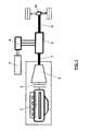
figure 1 shows a general scheme of a parallel hybrid driving system of a vehicle suitable to realize the method according to the invention; -
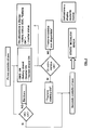
figures 2 ,3 and4 show the operating flowchart of the control method that is object of the invention, respectively referring to the starting steps of the vehicle, its functioning in hybrid and in electric mode. - With reference to
figure 1 , a parallel hybrid driving system comprises a internal combustion engine 1, an electric motor-generator 2, equipped with a DC/AC inverter 4 and with a high-voltageelectric traction battery 5, aclutch unit 3, and atransmission system 6 comprising a traditional manual-shift gear box. Theclutch 3 is placed between the internal combustion engine 1 and thetransmission system 6, while the electric motor-generator 2 is placed downstream of thetransmission system 6, on the shaft transmitting the torque to thebridge 10 of the driving axle. - The electric motor-
generator 2 is preferably placed between twosegments - With reference to
figures 2 ,3 and4 , the method for controlling the parallel hybrid driving system of the vehicle equipped with manual-shift gear box, that is object of the invention, is described in the following. - In order to actuate the method, there is a control logic, stored in one or more electronic control units that may at least in part be already present on the vehicle, with appropriate computer programs.
- For example, the control logic includes a control unit controlling the functioning of the electric motor-generator, which performs a bidirectional dialogue with a vehicle's control unit which dialogues in its turn with a control unit of the internal combustion engine.
- The control logic has at its disposal the indications coming from a control unit of the traction battery, with the indication SOC of the battery status of charge.
- The signals indicating the position of the accelerator pedal and of the clutch pedal are also available to the control unit. In particular, as regards the accelerator pedal the information on the speed of the position variation is also available; as regards the clutch pedal only an indication of the ON/OFF type, pedal completely released or completely pressed, is available.
- In general, the control method provides to give priority to the hybrid mode when the vehicle is used in extra-urban areas and to give priority to the only electric mode when the vehicle is used in urban areas.
- With reference to
figure 2 , at the first contact of the ignition key, the logic performs a control of the internal combustion engine and verifies if the internal combustion engine has any fault (MCI OK): in case of a fault, the logic provides a message asking to return to the repair shop (Return), because of faults of the internal combustion engine. - Moreover, always at the first contact of the ignition key, the logic verifies if: the system managing the traction battery is on (BMS ON), and if the inverter is on (Inverter ON). Then it verifies if batteries and inverter have errors or faults, if the status of charge (SOC) is higher than a predefined value, if the pre-charging procedure was successful and closed the power circuit of the batteries.
- These controls generate their respective warnings on a display at the driver's disposal: for example the status of charge of the battery (SOC), namely the percentage of instantaneous charge, if it is working (battery OK), and the state of the inverter.
- Said controls are integrated by a more general control of the status or the electric driving system (Electric Driveline OK). If it is negative, the message "Electric driving not available" is provided; on the contrary, if it is positive, the message provided is "Electric driving OK". Thus the logic generates the second contact of the key.
- If these controls are positive, the driving key is set in hybrid mode when the vehicle is started.
- The driving operating conditions are the following:
- the status of charge of the traction battery SOC has to be higher than a threshold SOCth , for example = 50%, below which the electric motor-generator cannot function as motor but only as electric generator;
- the control of the state of the clutch pedal is disabled;
- the regenerative braking function provided by the electric motor-generator is enabled;
- it is also possible to enable a function called "freewheeling", which automatically stops the internal combustion engine when the vehicle's speed is lower than a threshold Vt, for example 50 km/h, if the gear shift is in neutral.
- In hybrid mode the function "torque booster" is enabled wherein the electric engine may provide an additional torque with respect to the one generated by the internal combustion engine.
- The "Torque booster" CEM = f (SOC), namely the torque increase generated by the electric motor, is dependent on the status of charge of the battery.
- Moreover the torque delivered by the electric motor depends also on the position of the accelerator pedal CEM = f (Δa%), and on its derivative over time CEM = f (Δa%/ Δt) , namely the speed variation of the position, so that the entity of the increase of the torque generated by the electric motor depends also on the driving conditions determined by the driver and on the vehicle's speed.
- Therefore in hybrid mode the driving type may be determined either by the internal combustion engine only, or by the electric motor only, or by both, in "Torque booster" mode.
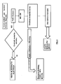
- With reference to
figure 3 , it is possible to shift from the hybrid to the electric mode, by means of a manual-driven control, for example when travelling in urban areas. The driver may act on a button or on a switch on the dashboard (PUSH button selector D) in order to activate the "electric only" mode. In these conditions, the control logic verifies the enabling conditions of this mode. In particular: - if the vehicle's speed is lower than a threshold, for example 50 km/h or a different threshold;
- if the manual-shift gear box, controlled by the driver is in neutral (gear shifting in N); thus a micro-switch is present in order to detect the position in neutral of the gear shifting;
- if the status of charge SOC of the traction batteries is higher than a minimum percentage value SOCmin, for example 25% of the highest value;
- if no faults are detected (Faults = 0).
- Then the logic enables the switching to the electric mode, wherein the internal combustion engine is stopped (MCI off), otherwise the vehicle keeps working in hybrid mode. Also these controls generate their respective warnings on a display available to the driver.
- In electric mode (Traction enable ON) the logic continually controls:
- if the speed is lower than the threshold;
- if the status of charge of the traction battery is higher than SOCmin ;
- if the gear shift is in neutral:
- if the clutch pedal is in OFF state, so that if it is operated, the vehicle switches to the hybrid mode. Moreover the logic enables the regenerative braking function of the electric motor-generator, and enables the electric traction with a generation of the traction torque that is proportional to the pressure on the accelerator pedal.
- With reference to
figure 4 , the driving system remains in electric mode if the previous controls continue to be positive. - The vehicle is automatically switched back to the hybrid mode when the previous controls are no longer positive, or it is manually switched to the hybrid mode by the driver which act on the clutch pedal (PUSH CLUTCH) (a micro-switch is present which detect if the clutch is released or pressed), or if the status of charge of the traction battery becomes lower than a minimum value, for example the value SOCmin mentioned above, or a different value, for example 20%.
- In this case the internal combustion engine is started again (MCI ON) and the driver acts on the gear shift (manually shifts gear) activating again the hybrid mode. The control logic is also able to manage emergency situations.
- In case of electric mode, it verifies the cases of faults of the electric drive and of the vehicle: in this case it starts the driving of the internal combustion engine only. In case of hybrid mode, it verifies the cases of faults of the internal combustion engine and of the vehicle: in this case it starts a traction by means of the electric motor only.
- The present invention may advantageously be realized by means of computer programs loaded on the various electronic control units of the vehicle, which comprises program code means performing one or more steps of said method, when said program is run on a computer. For this reason the scope of the present patent is meant to cover also said computer programs and the computer-readable means that comprise a recorded message, such computer-readable means comprising the program code means for performing one or more steps of such method, when such programs are run on a computer.
- It will be apparent to the person skilled in the art that other alternative and equivalent embodiments of the invention can be conceived and reduced to practice without departing from the scope of the invention.
- From the description set forth above it will be possible for the person skilled in the art to embody the invention with no need of describing further construction details.
Claims (7)
- Method for controlling a parallel hybrid driving system for a vehicle equipped with manual-shift gear box (6), clutch (3), internal combustion engine (1), electric motor-generator (2) and traction batteries, the method being suitable for controlling the functioning of the driving system according to a hybrid mode and an electric mode, and comprising the steps of:- determining at the starting of the internal combustion engine (1) the functioning in hybrid mode, conditional upon a first fault verification in said electric engine-generator (2);- determining the shifting to said electric mode, manual driven, wherein the internal combustion engine (1) is stopped, if:- the vehicle's speed is lower than a first threshold;- manual-shift gear box (6) is in neutral;- the status of charge of the traction batteries is higher than a minimum percentage value (SOCmin);- if no faults are detected (Faults = 0);otherwise the hybrid mode is maintained or there is a shifting to the hybrid mode by acting on the clutch.
- Method according to claim 1, in which said hybrid mode comprises the steps of:- verifying that the status of charge (SOC) of the traction battery is higher than a threshold (SOCth) , below which the electric motor-generator cannot function as motor but only as electric generator;- enabling the regenerative braking function provided by the electric motor-generator;- enabling the "torque booster" function wherein the electric motor-generator is suitable to provide additional torque to the one generated by the internal combustion engine, said additional torque being proportional to said status of charge (SOC) of the traction battery and being dependent on the position of the accelerator pedal (CEM = f (Δao%)), and on its derivative over time (CEM = f (Δa%/ Δt)) and on the vehicle's speed.
- Method according to claim 2, wherein said hybrid mode comprises the step enabling a "freewheeling" function, wherein the automatic stopping of the internal combustion engine is determined if the vehicle's speed is lower than a threshold ( Vt) with the gear shift in neutral.
- Method according to claim 1, in which said first fault verification comprises: verification that the management system of the traction batteries is working; verification of the state of the electric traction system.
- Parallel hybrid driving system for a vehicle equipped with manual-shift gear box (6), wherein said electric motor-generator (2) is placed downstream of said manual-shift gear box (6) on the transmission shaft (7, 8), and said system comprises a control logic suitable to realize the method of any of the previous claims.
- Computer program comprising program code means suitable for performing the steps of any claim from 1 to 4, when such program is run on a computer.
- Computer-readable means comprising a recorded program, said computer-readable means comprising program code means suitable for performing the steps according to the claims from 1 to 4, when said program is run on a computer.
Priority Applications (2)
| Application Number | Priority Date | Filing Date | Title |
|---|---|---|---|
| EP10425203A EP2397385B1 (en) | 2010-06-16 | 2010-06-16 | Method for controlling a parallel hybrid driving system for a vehicle equiped with a manual transmission and corresponding drivind system |
| ES10425203T ES2409271T3 (en) | 2010-06-16 | 2010-06-16 | Method for controlling a parallel hybrid driving system for a vehicle equipped with a manual transmission and corresponding driving system |
Applications Claiming Priority (1)
| Application Number | Priority Date | Filing Date | Title |
|---|---|---|---|
| EP10425203A EP2397385B1 (en) | 2010-06-16 | 2010-06-16 | Method for controlling a parallel hybrid driving system for a vehicle equiped with a manual transmission and corresponding drivind system |
Publications (2)
| Publication Number | Publication Date |
|---|---|
| EP2397385A1 true EP2397385A1 (en) | 2011-12-21 |
| EP2397385B1 EP2397385B1 (en) | 2013-03-06 |
Family
ID=42938541
Family Applications (1)
| Application Number | Title | Priority Date | Filing Date |
|---|---|---|---|
| EP10425203A Active EP2397385B1 (en) | 2010-06-16 | 2010-06-16 | Method for controlling a parallel hybrid driving system for a vehicle equiped with a manual transmission and corresponding drivind system |
Country Status (2)
| Country | Link |
|---|---|
| EP (1) | EP2397385B1 (en) |
| ES (1) | ES2409271T3 (en) |
Cited By (3)
| Publication number | Priority date | Publication date | Assignee | Title |
|---|---|---|---|---|
| CN103204155A (en) * | 2012-01-11 | 2013-07-17 | 上海汽车集团股份有限公司 | Control method and control device for shift mode of vehicle hybrid power system |
| WO2016166464A1 (en) * | 2015-04-16 | 2016-10-20 | Renault S.A.S | Method and system for managing a change of mode of driving of an automotive vehicle |
| WO2017140620A1 (en) * | 2016-02-18 | 2017-08-24 | Audi Ag | Operating method for a vehicle and associated vehicle |
Families Citing this family (1)
| Publication number | Priority date | Publication date | Assignee | Title |
|---|---|---|---|---|
| CN103625462B (en) * | 2013-08-01 | 2016-08-17 | 河南科技大学 | The control method of energy-saving series hybrid-power tractor |
Citations (9)
| Publication number | Priority date | Publication date | Assignee | Title |
|---|---|---|---|---|
| US5176213A (en) * | 1987-12-09 | 1993-01-05 | Aisin Aw Co., Ltd. | Driving force distribution system for hybrid vehicles |
| DE4123843A1 (en) * | 1991-07-18 | 1993-01-21 | Man Nutzfahrzeuge Ag | Truck with chilled container - has hybrid drive with electric back=up motor cooling and engine-driven main cooling |
| EP0768204A1 (en) * | 1995-10-13 | 1997-04-16 | Toyota Jidosha Kabushiki Kaisha | Hybrid drive system for motor vehicle wherein upon failure of one of engine and electric motor, the normal engine or motor is operated to drive the vehicle |
| EP1034957A2 (en) * | 1999-03-09 | 2000-09-13 | Honda Giken Kogyo Kabushiki Kaisha | Engine control system for hybrid vehicle |
| US6209672B1 (en) * | 1998-09-14 | 2001-04-03 | Paice Corporation | Hybrid vehicle |
| EP1288051A2 (en) * | 2001-08-30 | 2003-03-05 | Toyota Jidosha Kabushiki Kaisha | Control apparatus and method of diesel hybrid vehicle |
| GB2413999A (en) * | 2004-05-10 | 2005-11-16 | Volkswagen Ag | Automatic stop-start control of a motor vehicles combustion engine |
| US20070102930A1 (en) * | 2005-10-28 | 2007-05-10 | Fujitsu Ten Limited | Starting control apparatus |
| DE102008042887A1 (en) * | 2008-10-16 | 2010-04-22 | Robert Bosch Gmbh | Method for increasing the availability of hybrid vehicles |
-
2010
- 2010-06-16 ES ES10425203T patent/ES2409271T3/en active Active
- 2010-06-16 EP EP10425203A patent/EP2397385B1/en active Active
Patent Citations (9)
| Publication number | Priority date | Publication date | Assignee | Title |
|---|---|---|---|---|
| US5176213A (en) * | 1987-12-09 | 1993-01-05 | Aisin Aw Co., Ltd. | Driving force distribution system for hybrid vehicles |
| DE4123843A1 (en) * | 1991-07-18 | 1993-01-21 | Man Nutzfahrzeuge Ag | Truck with chilled container - has hybrid drive with electric back=up motor cooling and engine-driven main cooling |
| EP0768204A1 (en) * | 1995-10-13 | 1997-04-16 | Toyota Jidosha Kabushiki Kaisha | Hybrid drive system for motor vehicle wherein upon failure of one of engine and electric motor, the normal engine or motor is operated to drive the vehicle |
| US6209672B1 (en) * | 1998-09-14 | 2001-04-03 | Paice Corporation | Hybrid vehicle |
| EP1034957A2 (en) * | 1999-03-09 | 2000-09-13 | Honda Giken Kogyo Kabushiki Kaisha | Engine control system for hybrid vehicle |
| EP1288051A2 (en) * | 2001-08-30 | 2003-03-05 | Toyota Jidosha Kabushiki Kaisha | Control apparatus and method of diesel hybrid vehicle |
| GB2413999A (en) * | 2004-05-10 | 2005-11-16 | Volkswagen Ag | Automatic stop-start control of a motor vehicles combustion engine |
| US20070102930A1 (en) * | 2005-10-28 | 2007-05-10 | Fujitsu Ten Limited | Starting control apparatus |
| DE102008042887A1 (en) * | 2008-10-16 | 2010-04-22 | Robert Bosch Gmbh | Method for increasing the availability of hybrid vehicles |
Cited By (7)
| Publication number | Priority date | Publication date | Assignee | Title |
|---|---|---|---|---|
| CN103204155A (en) * | 2012-01-11 | 2013-07-17 | 上海汽车集团股份有限公司 | Control method and control device for shift mode of vehicle hybrid power system |
| CN103204155B (en) * | 2012-01-11 | 2016-01-13 | 上海汽车集团股份有限公司 | A kind of control method of hybrid power system for automobile shift mode and control setup |
| WO2016166464A1 (en) * | 2015-04-16 | 2016-10-20 | Renault S.A.S | Method and system for managing a change of mode of driving of an automotive vehicle |
| FR3035054A1 (en) * | 2015-04-16 | 2016-10-21 | Renault Sa | METHOD AND SYSTEM FOR MANAGING A CHANGE IN DRIVING MODE OF A MOTOR VEHICLE |
| KR20170138503A (en) * | 2015-04-16 | 2017-12-15 | 르노 에스.아.에스. | Method and system for managing driving mode change of an automobile vehicle |
| KR102468810B1 (en) | 2015-04-16 | 2022-11-18 | 르노 에스.아.에스. | Method and system for managing driving mode change of motor vehicles |
| WO2017140620A1 (en) * | 2016-02-18 | 2017-08-24 | Audi Ag | Operating method for a vehicle and associated vehicle |
Also Published As
| Publication number | Publication date |
|---|---|
| EP2397385B1 (en) | 2013-03-06 |
| ES2409271T3 (en) | 2013-06-26 |
Similar Documents
| Publication | Publication Date | Title |
|---|---|---|
| US8708090B2 (en) | Power steering system for a vehicle provided with means for actuating the stop and start function in a moving vehicle, especially an industrial or commercial or special vehicle | |
| US8666594B2 (en) | Method for actuating the stop and start function in a moving vehicle, especially an industrial or commercial or special vehicle | |
| US7823668B2 (en) | Control device for a hybrid electric vehicle | |
| JP5360306B2 (en) | Control device for hybrid vehicle | |
| KR100858200B1 (en) | Control device of hybrid electric vehicle | |
| US9085298B2 (en) | Power transmission control device for vehicle | |
| US9623861B2 (en) | Hybrid vehicle | |
| JP2013071551A (en) | Control apparatus of hybrid vehicle | |
| JP2014034388A (en) | Start control device and method for hybrid electric vehicle | |
| KR101836289B1 (en) | Engine clutch cotrolling apparatus for green car and method of thesame | |
| EP2857272B1 (en) | Vehicle control unit | |
| KR101490922B1 (en) | Method and system for changing drive mode when battery power of hybrid vehicle is limited | |
| KR101776761B1 (en) | Method and appratus of determining performance of battery for mild hybrid electric vehicle | |
| US20210188254A1 (en) | Electric vehicle and control method for electric vehicle | |
| EP2397385B1 (en) | Method for controlling a parallel hybrid driving system for a vehicle equiped with a manual transmission and corresponding drivind system | |
| US8612080B2 (en) | Method for operating a hybrid drive | |
| JP2006077641A (en) | Control device for hybrid electric automobile | |
| CN107585156B (en) | Shift control apparatus for vehicle | |
| EP2397355B1 (en) | Control method for a parallel hybrid traction system for a vehicle with an automatic transmission | |
| JP2014088056A (en) | Control system of hybrid electric vehicle | |
| KR101907985B1 (en) | Method and apparatus for controlling engine clutch of hybrid vehicle | |
| KR101449323B1 (en) | Device and method for controlling clutch of hybrid vehicle | |
| KR102001110B1 (en) | Method and apparatus for controlling transmission of hybrid vehicle | |
| KR101964771B1 (en) | Method and apparatus for controlling transmission of hybrid vehicle | |
| WO2015037042A1 (en) | Hybrid vehicle control device |
Legal Events
| Date | Code | Title | Description |
|---|---|---|---|
| AK | Designated contracting states |
Kind code of ref document: A1 Designated state(s): AL AT BE BG CH CY CZ DE DK EE ES FI FR GB GR HR HU IE IS IT LI LT LU LV MC MK MT NL NO PL PT RO SE SI SK SM TR |
|
| AX | Request for extension of the european patent |
Extension state: BA ME RS |
|
| PUAI | Public reference made under article 153(3) epc to a published international application that has entered the european phase |
Free format text: ORIGINAL CODE: 0009012 |
|
| 17P | Request for examination filed |
Effective date: 20120620 |
|
| RIC1 | Information provided on ipc code assigned before grant |
Ipc: B60K 6/48 20071001ALI20120802BHEP Ipc: B60W 10/06 20060101AFI20120802BHEP Ipc: B60W 50/02 20120101ALI20120802BHEP Ipc: B60W 20/00 20060101ALI20120802BHEP Ipc: B60L 11/14 20060101ALI20120802BHEP Ipc: B60W 10/02 20060101ALI20120802BHEP Ipc: B60L 3/00 20060101ALI20120802BHEP Ipc: B60W 10/08 20060101ALI20120802BHEP Ipc: B60L 15/20 20060101ALI20120802BHEP |
|
| GRAP | Despatch of communication of intention to grant a patent |
Free format text: ORIGINAL CODE: EPIDOSNIGR1 |
|
| GRAS | Grant fee paid |
Free format text: ORIGINAL CODE: EPIDOSNIGR3 |
|
| GRAA | (expected) grant |
Free format text: ORIGINAL CODE: 0009210 |
|
| AK | Designated contracting states |
Kind code of ref document: B1 Designated state(s): AL AT BE BG CH CY CZ DE DK EE ES FI FR GB GR HR HU IE IS IT LI LT LU LV MC MK MT NL NO PL PT RO SE SI SK SM TR |
|
| REG | Reference to a national code |
Ref country code: GB Ref legal event code: FG4D |
|
| REG | Reference to a national code |
Ref country code: CH Ref legal event code: EP Ref country code: AT Ref legal event code: REF Ref document number: 599419 Country of ref document: AT Kind code of ref document: T Effective date: 20130315 |
|
| REG | Reference to a national code |
Ref country code: IE Ref legal event code: FG4D |
|
| REG | Reference to a national code |
Ref country code: DE Ref legal event code: R096 Ref document number: 602010005262 Country of ref document: DE Effective date: 20130502 |
|
| REG | Reference to a national code |
Ref country code: SE Ref legal event code: TRGR |
|
| REG | Reference to a national code |
Ref country code: ES Ref legal event code: FG2A Ref document number: 2409271 Country of ref document: ES Kind code of ref document: T3 Effective date: 20130626 |
|
| REG | Reference to a national code |
Ref country code: AT Ref legal event code: MK05 Ref document number: 599419 Country of ref document: AT Kind code of ref document: T Effective date: 20130306 |
|
| REG | Reference to a national code |
Ref country code: NL Ref legal event code: T3 |
|
| PG25 | Lapsed in a contracting state [announced via postgrant information from national office to epo] |
Ref country code: NO Free format text: LAPSE BECAUSE OF FAILURE TO SUBMIT A TRANSLATION OF THE DESCRIPTION OR TO PAY THE FEE WITHIN THE PRESCRIBED TIME-LIMIT Effective date: 20130606 Ref country code: BG Free format text: LAPSE BECAUSE OF FAILURE TO SUBMIT A TRANSLATION OF THE DESCRIPTION OR TO PAY THE FEE WITHIN THE PRESCRIBED TIME-LIMIT Effective date: 20130606 Ref country code: AT Free format text: LAPSE BECAUSE OF FAILURE TO SUBMIT A TRANSLATION OF THE DESCRIPTION OR TO PAY THE FEE WITHIN THE PRESCRIBED TIME-LIMIT Effective date: 20130306 Ref country code: LT Free format text: LAPSE BECAUSE OF FAILURE TO SUBMIT A TRANSLATION OF THE DESCRIPTION OR TO PAY THE FEE WITHIN THE PRESCRIBED TIME-LIMIT Effective date: 20130306 |
|
| REG | Reference to a national code |
Ref country code: LT Ref legal event code: MG4D |
|
| PG25 | Lapsed in a contracting state [announced via postgrant information from national office to epo] |
Ref country code: GR Free format text: LAPSE BECAUSE OF FAILURE TO SUBMIT A TRANSLATION OF THE DESCRIPTION OR TO PAY THE FEE WITHIN THE PRESCRIBED TIME-LIMIT Effective date: 20130607 Ref country code: FI Free format text: LAPSE BECAUSE OF FAILURE TO SUBMIT A TRANSLATION OF THE DESCRIPTION OR TO PAY THE FEE WITHIN THE PRESCRIBED TIME-LIMIT Effective date: 20130306 Ref country code: LV Free format text: LAPSE BECAUSE OF FAILURE TO SUBMIT A TRANSLATION OF THE DESCRIPTION OR TO PAY THE FEE WITHIN THE PRESCRIBED TIME-LIMIT Effective date: 20130306 Ref country code: SI Free format text: LAPSE BECAUSE OF FAILURE TO SUBMIT A TRANSLATION OF THE DESCRIPTION OR TO PAY THE FEE WITHIN THE PRESCRIBED TIME-LIMIT Effective date: 20130306 |
|
| PG25 | Lapsed in a contracting state [announced via postgrant information from national office to epo] |
Ref country code: BE Free format text: LAPSE BECAUSE OF FAILURE TO SUBMIT A TRANSLATION OF THE DESCRIPTION OR TO PAY THE FEE WITHIN THE PRESCRIBED TIME-LIMIT Effective date: 20130306 Ref country code: HR Free format text: LAPSE BECAUSE OF FAILURE TO SUBMIT A TRANSLATION OF THE DESCRIPTION OR TO PAY THE FEE WITHIN THE PRESCRIBED TIME-LIMIT Effective date: 20130306 |
|
| PG25 | Lapsed in a contracting state [announced via postgrant information from national office to epo] |
Ref country code: RO Free format text: LAPSE BECAUSE OF FAILURE TO SUBMIT A TRANSLATION OF THE DESCRIPTION OR TO PAY THE FEE WITHIN THE PRESCRIBED TIME-LIMIT Effective date: 20130306 Ref country code: PT Free format text: LAPSE BECAUSE OF FAILURE TO SUBMIT A TRANSLATION OF THE DESCRIPTION OR TO PAY THE FEE WITHIN THE PRESCRIBED TIME-LIMIT Effective date: 20130708 Ref country code: EE Free format text: LAPSE BECAUSE OF FAILURE TO SUBMIT A TRANSLATION OF THE DESCRIPTION OR TO PAY THE FEE WITHIN THE PRESCRIBED TIME-LIMIT Effective date: 20130306 Ref country code: IS Free format text: LAPSE BECAUSE OF FAILURE TO SUBMIT A TRANSLATION OF THE DESCRIPTION OR TO PAY THE FEE WITHIN THE PRESCRIBED TIME-LIMIT Effective date: 20130706 Ref country code: SK Free format text: LAPSE BECAUSE OF FAILURE TO SUBMIT A TRANSLATION OF THE DESCRIPTION OR TO PAY THE FEE WITHIN THE PRESCRIBED TIME-LIMIT Effective date: 20130306 Ref country code: CZ Free format text: LAPSE BECAUSE OF FAILURE TO SUBMIT A TRANSLATION OF THE DESCRIPTION OR TO PAY THE FEE WITHIN THE PRESCRIBED TIME-LIMIT Effective date: 20130306 |
|
| PG25 | Lapsed in a contracting state [announced via postgrant information from national office to epo] |
Ref country code: PL Free format text: LAPSE BECAUSE OF FAILURE TO SUBMIT A TRANSLATION OF THE DESCRIPTION OR TO PAY THE FEE WITHIN THE PRESCRIBED TIME-LIMIT Effective date: 20130306 |
|
| PLBE | No opposition filed within time limit |
Free format text: ORIGINAL CODE: 0009261 |
|
| STAA | Information on the status of an ep patent application or granted ep patent |
Free format text: STATUS: NO OPPOSITION FILED WITHIN TIME LIMIT |
|
| PG25 | Lapsed in a contracting state [announced via postgrant information from national office to epo] |
Ref country code: MC Free format text: LAPSE BECAUSE OF FAILURE TO SUBMIT A TRANSLATION OF THE DESCRIPTION OR TO PAY THE FEE WITHIN THE PRESCRIBED TIME-LIMIT Effective date: 20130306 Ref country code: DK Free format text: LAPSE BECAUSE OF FAILURE TO SUBMIT A TRANSLATION OF THE DESCRIPTION OR TO PAY THE FEE WITHIN THE PRESCRIBED TIME-LIMIT Effective date: 20130306 |
|
| 26N | No opposition filed |
Effective date: 20131209 |
|
| REG | Reference to a national code |
Ref country code: DE Ref legal event code: R097 Ref document number: 602010005262 Country of ref document: DE Effective date: 20131209 |
|
| REG | Reference to a national code |
Ref country code: IE Ref legal event code: MM4A |
|
| PG25 | Lapsed in a contracting state [announced via postgrant information from national office to epo] |
Ref country code: IE Free format text: LAPSE BECAUSE OF NON-PAYMENT OF DUE FEES Effective date: 20130616 |
|
| REG | Reference to a national code |
Ref country code: CH Ref legal event code: PL |
|
| PG25 | Lapsed in a contracting state [announced via postgrant information from national office to epo] |
Ref country code: MT Free format text: LAPSE BECAUSE OF FAILURE TO SUBMIT A TRANSLATION OF THE DESCRIPTION OR TO PAY THE FEE WITHIN THE PRESCRIBED TIME-LIMIT Effective date: 20130306 |
|
| PG25 | Lapsed in a contracting state [announced via postgrant information from national office to epo] |
Ref country code: CH Free format text: LAPSE BECAUSE OF NON-PAYMENT OF DUE FEES Effective date: 20140630 Ref country code: LI Free format text: LAPSE BECAUSE OF NON-PAYMENT OF DUE FEES Effective date: 20140630 |
|
| PG25 | Lapsed in a contracting state [announced via postgrant information from national office to epo] |
Ref country code: SM Free format text: LAPSE BECAUSE OF FAILURE TO SUBMIT A TRANSLATION OF THE DESCRIPTION OR TO PAY THE FEE WITHIN THE PRESCRIBED TIME-LIMIT Effective date: 20130306 |
|
| PG25 | Lapsed in a contracting state [announced via postgrant information from national office to epo] |
Ref country code: CY Free format text: LAPSE BECAUSE OF FAILURE TO SUBMIT A TRANSLATION OF THE DESCRIPTION OR TO PAY THE FEE WITHIN THE PRESCRIBED TIME-LIMIT Effective date: 20130306 Ref country code: TR Free format text: LAPSE BECAUSE OF FAILURE TO SUBMIT A TRANSLATION OF THE DESCRIPTION OR TO PAY THE FEE WITHIN THE PRESCRIBED TIME-LIMIT Effective date: 20130306 |
|
| PG25 | Lapsed in a contracting state [announced via postgrant information from national office to epo] |
Ref country code: MK Free format text: LAPSE BECAUSE OF FAILURE TO SUBMIT A TRANSLATION OF THE DESCRIPTION OR TO PAY THE FEE WITHIN THE PRESCRIBED TIME-LIMIT Effective date: 20130306 Ref country code: HU Free format text: LAPSE BECAUSE OF FAILURE TO SUBMIT A TRANSLATION OF THE DESCRIPTION OR TO PAY THE FEE WITHIN THE PRESCRIBED TIME-LIMIT; INVALID AB INITIO Effective date: 20100616 Ref country code: LU Free format text: LAPSE BECAUSE OF NON-PAYMENT OF DUE FEES Effective date: 20130616 |
|
| REG | Reference to a national code |
Ref country code: FR Ref legal event code: PLFP Year of fee payment: 7 |
|
| REG | Reference to a national code |
Ref country code: FR Ref legal event code: PLFP Year of fee payment: 8 |
|
| REG | Reference to a national code |
Ref country code: FR Ref legal event code: PLFP Year of fee payment: 9 |
|
| PG25 | Lapsed in a contracting state [announced via postgrant information from national office to epo] |
Ref country code: AL Free format text: LAPSE BECAUSE OF FAILURE TO SUBMIT A TRANSLATION OF THE DESCRIPTION OR TO PAY THE FEE WITHIN THE PRESCRIBED TIME-LIMIT Effective date: 20130306 |
|
| RIC2 | Information provided on ipc code assigned after grant |
Ipc: B60W 10/08 20060101ALI20120802BHEP Ipc: B60W 10/06 20060101AFI20120802BHEP Ipc: B60L 11/14 20060101ALI20120802BHEP Ipc: B60W 20/00 20160101ALI20120802BHEP Ipc: B60L 3/00 20190101ALI20120802BHEP Ipc: B60K 6/48 20071001ALI20120802BHEP Ipc: B60W 50/02 20120101ALI20120802BHEP Ipc: B60L 15/20 20060101ALI20120802BHEP Ipc: B60W 10/02 20060101ALI20120802BHEP |
|
| P01 | Opt-out of the competence of the unified patent court (upc) registered |
Effective date: 20230519 |
|
| PGFP | Annual fee paid to national office [announced via postgrant information from national office to epo] |
Ref country code: NL Payment date: 20230626 Year of fee payment: 14 Ref country code: IT Payment date: 20230614 Year of fee payment: 14 Ref country code: FR Payment date: 20230622 Year of fee payment: 14 Ref country code: DE Payment date: 20230627 Year of fee payment: 14 |
|
| PGFP | Annual fee paid to national office [announced via postgrant information from national office to epo] |
Ref country code: SE Payment date: 20230626 Year of fee payment: 14 |
|
| PGFP | Annual fee paid to national office [announced via postgrant information from national office to epo] |
Ref country code: GB Payment date: 20230620 Year of fee payment: 14 Ref country code: ES Payment date: 20230721 Year of fee payment: 14 |