EP2394695A1 - Standalone intracardiac capsule and implantation accessory - Google Patents
Standalone intracardiac capsule and implantation accessory Download PDFInfo
- Publication number
- EP2394695A1 EP2394695A1 EP11157822A EP11157822A EP2394695A1 EP 2394695 A1 EP2394695 A1 EP 2394695A1 EP 11157822 A EP11157822 A EP 11157822A EP 11157822 A EP11157822 A EP 11157822A EP 2394695 A1 EP2394695 A1 EP 2394695A1
- Authority
- EP
- European Patent Office
- Prior art keywords
- capsule
- assembly
- helical guide
- helical
- guide
- Prior art date
- Legal status (The legal status is an assumption and is not a legal conclusion. Google has not performed a legal analysis and makes no representation as to the accuracy of the status listed.)
- Granted
Links
Images
Classifications
-
- A—HUMAN NECESSITIES
- A61—MEDICAL OR VETERINARY SCIENCE; HYGIENE
- A61N—ELECTROTHERAPY; MAGNETOTHERAPY; RADIATION THERAPY; ULTRASOUND THERAPY
- A61N1/00—Electrotherapy; Circuits therefor
- A61N1/18—Applying electric currents by contact electrodes
- A61N1/32—Applying electric currents by contact electrodes alternating or intermittent currents
- A61N1/36—Applying electric currents by contact electrodes alternating or intermittent currents for stimulation
- A61N1/372—Arrangements in connection with the implantation of stimulators
- A61N1/375—Constructional arrangements, e.g. casings
- A61N1/37518—Anchoring of the implants, e.g. fixation
-
- A—HUMAN NECESSITIES
- A61—MEDICAL OR VETERINARY SCIENCE; HYGIENE
- A61N—ELECTROTHERAPY; MAGNETOTHERAPY; RADIATION THERAPY; ULTRASOUND THERAPY
- A61N1/00—Electrotherapy; Circuits therefor
- A61N1/02—Details
- A61N1/04—Electrodes
- A61N1/05—Electrodes for implantation or insertion into the body, e.g. heart electrode
- A61N1/0587—Epicardial electrode systems; Endocardial electrodes piercing the pericardium
- A61N1/059—Anchoring means
-
- A—HUMAN NECESSITIES
- A61—MEDICAL OR VETERINARY SCIENCE; HYGIENE
- A61N—ELECTROTHERAPY; MAGNETOTHERAPY; RADIATION THERAPY; ULTRASOUND THERAPY
- A61N1/00—Electrotherapy; Circuits therefor
- A61N1/02—Details
- A61N1/04—Electrodes
- A61N1/05—Electrodes for implantation or insertion into the body, e.g. heart electrode
- A61N1/056—Transvascular endocardial electrode systems
- A61N1/057—Anchoring means; Means for fixing the head inside the heart
- A61N1/0573—Anchoring means; Means for fixing the head inside the heart chacterised by means penetrating the heart tissue, e.g. helix needle or hook
-
- A—HUMAN NECESSITIES
- A61—MEDICAL OR VETERINARY SCIENCE; HYGIENE
- A61N—ELECTROTHERAPY; MAGNETOTHERAPY; RADIATION THERAPY; ULTRASOUND THERAPY
- A61N1/00—Electrotherapy; Circuits therefor
- A61N1/18—Applying electric currents by contact electrodes
- A61N1/32—Applying electric currents by contact electrodes alternating or intermittent currents
- A61N1/36—Applying electric currents by contact electrodes alternating or intermittent currents for stimulation
- A61N1/372—Arrangements in connection with the implantation of stimulators
- A61N1/375—Constructional arrangements, e.g. casings
- A61N1/3756—Casings with electrodes thereon, e.g. leadless stimulators
-
- A—HUMAN NECESSITIES
- A61—MEDICAL OR VETERINARY SCIENCE; HYGIENE
- A61N—ELECTROTHERAPY; MAGNETOTHERAPY; RADIATION THERAPY; ULTRASOUND THERAPY
- A61N1/00—Electrotherapy; Circuits therefor
- A61N1/02—Details
- A61N1/04—Electrodes
- A61N1/05—Electrodes for implantation or insertion into the body, e.g. heart electrode
- A61N1/056—Transvascular endocardial electrode systems
- A61N1/057—Anchoring means; Means for fixing the head inside the heart
- A61N2001/058—Fixing tools
Definitions
- the invention relates to "active implantable medical devices" as defined by Council Directive 90/385 / EEC of 20 June 1990; plus implants for continuous monitoring of the heart rate and deliver if necessary heart electrical pacing pulses, cardioversion and / or defibrillation in case of rhythm disorder detected by the device,
- It relates more particularly to those devices which use autonomous capsules implanted in a heart chamber, ventricle or atrium, and which are devoid of any physical connection to an implanted main device (such as a pulse generator box of stimulation) or not implanted (external device such as programmer or monitoring device for remote monitoring of the patient).
- an implanted main device such as a pulse generator box of stimulation
- external device such as programmer or monitoring device for remote monitoring of the patient.
- Such leadless capsules are for example described in US 2007/0088397 A1 and WO 2007/047681 A2 (Nanostim Inc.) or in the US 2008/0136004 A1 (EBR Systems, Inc.)
- the attachment to the cardiac wall of these capsules is generally done by means of a protruding helical anchoring screw, axially extending the cylindrical body of the capsule and intended to penetrate into the heart tissue by screwing to the implantation site.
- these capsules incorporate wireless communication transmitter / receiver means with this remote master device
- the capsule can also incorporate a sensor for locally measuring the value of a parameter such as the level of oxygen in the blood, the acceleration of the heart wall, etc.
- These capsules may also be detection / stimulation capsules comprising means for collecting myocardial depolarization potential, and / or for apply stimulation pulses to the site where the capsule is implanted.
- the capsule then carries a suitable electrode, which may in particular be constituted by an active portion of the anchor screw.
- the present invention relates more specifically to the delivery of the leadless capsules , that is to say their placement at the site of chosen implantation.
- the invention is not limited to a particular type of capsule, and it is applicable regardless of any type of leadless capsule, regardless of its functional purpose.
- the leadless capsules may be epicardial capsules attached to the outer wall of the heart, or capsules in docavitaries, attached to the inner wall of a ventricular or atrial cavity.
- the implantation constraints are increased because of the approach pathway, which involves passing through the peripheral venous network and then directing the capsule to the chosen implantation site, under a brightness amplifier. a way that is both precise and perfectly secure. It is only once the site is reached and the capsule anchored in the wall that the operator can proceed to the "release" of this capsule, that is to say, its disengagement from the installation accessory .
- the US 2009/0204170 A (Cardiac Pacemakers, Inc.) describes a leadless electrostimulation capsule and a tool for its placement, in which the capsule is delivered through a catheter to the implantation site inside a carrier tube applied against the cardiac wall, then gradually screwed into the latter by a drive mandrel extending into the catheter lumen.
- the invention proposes for this purpose a set of intracardiac capsule with its implanting accessory in situ including, in a manner known in particular from the US 2009/0204170 A1 aforementioned: an autonomous capsule, comprising a cylindrical tubular body provided at one of its ends with a protruding helical anchoring screw axially extending the cylindrical body, and able to penetrate the tissue of the wall of a cavity of the heart this capsule comprising at least one coupling finger integral with the cylindrical body and projecting radially outwards, and an accessory for implanting the capsule, comprising means for releasably supporting and guiding the capsule to the site of implantation, and rotational drive of this capsule to allow simultaneous driving of the screw and its anchoring by penetration into the wall of the cavity of the heart.
- the implantation accessory comprises a probe body with a sheath of deformable material bearing on the distal side a helical guide forming said detachable means for supporting, guiding and driving in rotation of the capsule.
- the helical guide axially extends the probe body and is integral therewith in rotation and in translation, the inner diameter of the helical guide is homologous to the outer diameter of the cylindrical body of the capsule so as to accommodate it to the interior, the coupling finger (s) protruding between the turns of the helical guide, and the direction of the helical guide is opposite that of the anchor screw.
- the capsule preferably consists of two coupling fingers, one in the distal portion and the other in the proximal portion,
- the helical guide is a protruding helix axially extending the distal end of the probe body, in particular an elastically compressible helix in the axial direction and whose helical pitch is increased in its free distal end portion.
- the capsule comprising two coupling fingers, one in distal part and the other in the proximal part, the axial spacing of these two coupling fingers is chosen, so as to provide a compression of the helix when the cylindrical body of the capsule is completely housed inside the helical guide.
- this set comprises a soluble protection coating including the capsule provided with its anchor screw with the helical guide.
- the capsule may furthermore comprise a resetting ramp extending the coupling finger located in the distal portion, this ramp forming a fraction of a helical thread with a direction of transmission opposite to that of the helical guide, and being able to come into contact with its proximal flank with the free end of the helical guide.
- the distal end of the probe body carries a cylindrical hollow tube extending axially and forming a housing adapted to contain the capsule, the helical guide being a helical groove formed in the inner surface of this housing, and means are provided for deploying the anchor screw by a pin-driven drive .
- the pitch of the helical guide is increased in its free distal end portion.
- the capsule having two coupling fingers, one in the distal portion and the other in the proximal portion, the axial spacing of these two coupling fingers is selected so as to provide compression of the spring when the cylindrical body of the capsule is completely housed inside the helical guide.
- the assembly may further comprise a flexible wire disposed in a lumen of the probe body and connecting the capsule to the end proximal of the probe body over the entire length thereof, the wire comprising in the vicinity of the point of connection to the capsule a portion made of a resorbable material.
- the capsule may in particular be a detection / stimulation capsule comprising means for collecting depolarization potentials and / or for applying stimulation pulses coupled to at least one electrode carried by the capsule, in particular an electrode consisting of an active part anchor screw, and wireless communication transmitter / receiver means with a remote master device.
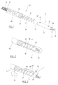
- reference numeral 10 denotes an autonomous capsule of leadless type, comprising in itself known manner a cylindrical tubular body 12, provided at one of its ends with a protruding helical screw anchoring screw 14 axially extending the tubular body 12 and secured to it in rotation.
- the anchoring screw 14 is advantageously made with a distal portion 16 formed over a length of the order of 1.5 to 2 mm of non-contiguous turns intended to penetrate into the cardiac tissue.
- This distal portion 16 is connected to the tubular body 12 via a mechanical transition portion 18 having flexural flexibility, for example a portion formed of contiguous turns in the absence of stress on the screw.
- the anchoring screw 14 can be an electrically active screw, that is to say playing, at least at its distal end, the role of detection and / or stimulation electrode, or a passive screw serving only anchoring the tubular body 12 in the wall of the heart chamber.
- the tubular body 12 includes various means and power supply circuits, signal processing and wireless communication to allow the exchange of signals with a remote master device, implanted or not. These aspects are in themselves known and, as they are not part of the invention, they will not be described; reference may be made to the various publications cited at the beginning of this description for more details on this subject.
- the tubular body 12 is cylindrical and, in a characteristic manner of the invention, carries at least one coupling finger in the form of an axially skilful protuberance, the function of which will be explained below.
- the capsule comprises two of these coupling fingers, situated on one distal side, the other 22 proximal side, with an axial spacing having a predetermined value (the importance of this characteristic will be explained below).
- the shape of these coupling fingers 20, 22 may be adapted to give them a softened, atraumatic profile.
- the tubular body 12 has a length of the order of 5 to 10 mm and a diameter of the order of 1 to 2 mm (6 French).
- the proximal end 24 of the capsule 10 may be rounded or ogival-shaped to, on the one hand, make it atraumatic and, on the other hand, facilitate its coupling with the fitting accessory.
- FIGS. 1 to 3 illustrate a first embodiment of installation accessory 26 for the introduction of the capsule 10.
- This accessory comprises, essentially, a body 28 structurally similar to a monopolar-type probe body, that is to say with a structure in itself known having along its length a spiral conductor 30 coated with a sheath 32
- the sheath 32 is generally made of polyurethane, to limit friction when the probe body is introduced into a guide catheter or into the venous network, and to provide better sensitivity and torque transmission.
- the conductor 30 has no electrical function, it only contributes to the mechanical behavior of the probe body 28 by further ensuring the radiopacity of the latter.
- the conductive assembly 30 / sheath 32 provides the probe body 28 with sufficient torsional rigidity to be able to transmit a torsion torque from its proximal end to its distal end to rotate this distal end.
- the distal end of the probe body 28 is provided with a tip 34 which is secured to a helical guide 36 formed, in this embodiment, of a propeller 38 made of an elastic material (for example an alloy of the M35N or rutinol type), making it possible to make the propeller 38 compressible in the axial direction in the manner of a helical compression spring.
- a propeller 38 made of an elastic material (for example an alloy of the M35N or rutinol type), making it possible to make the propeller 38 compressible in the axial direction in the manner of a helical compression spring.
- this helix-spring 38 has a pitch inverted with respect to the pitch of the helical anchoring screw 16 of the capsule, for example a step to the left if the anchoring screw has a step to the right.
- the spring-propeller 38 has at its free distal end a slightly elongated pitch, for example on the most distal coil 40
- the spring-propeller 38 is connected to the end piece 34 by a transition portion 42 having a certain flexibility in bending, for example a part 42 formed of contiguous turns in the absence of stress on the spring-coil 38,
- the body 12 of the capsule 10 is screwed into the helix spring 38, thus resulting in the illustrated configuration Figure 2 .
- the spacing of the coupling fingers 20, 22 is dimensioned so as to ensure, in this configuration, a slight compression of the helix-spring 38 when the distal coupling finger 20 initiates the coil 40 which, as has been exposed higher, has an elongated pitch with respect to the rest of the spring propeller 38.
- a soluble coating 44 for example polyethylene glycol (PEG),
- PEG polyethylene glycol
- the assembly is introduced to the cavity according to a conventional procedure, the probe body 28 being of standard construction. the practitioner will find the classic feelings of torque. flexibility, slip, etc.
- the doctor positions the end of the anchoring screw 14 against the cardiac wall, and begins the screwing, by rotation in the clockwise direction (corresponding to the right step of the anchor screw 14).
- the torque is transmitted from the proximal end of the probe body 28 and allows, at first, the penetration of the anchor screw 14 in the tissue of the wall 46 of the heart cavity.
- the corresponding value of the torque allowing this operation will be designated C screwing
- the Figure 3 illustrates the configuration of the assembly after a complete screwing: the front face of the capsule 10 abuts against the cardiac wall 46 and stops the progression of the anchor screw 14 also generating in return a sharp increase in the torque of reaction
- the anchoring screw 14 may then tear the tissue locally under the effect of the rotation of the screw without advance thereof, to cause laceration of tissues and. at the extreme, perforation of the wall with risk of tamponade.
- the doctor can indeed continue without risk the rotation, always in the clockwise direction, of the probe body 28 because the additional torque occurring because of the reaction of the Screw 14 anchored in the tissue is absorbed by the connection between the spring propeller 38 and the capsule 10. More precisely. the elasticity in compression of the spring-propeller 38 is chosen so as to define a sliding torque C slightly less than the coring limit C coring, so that when the sliding torque C is reached, the further rotation of the The probe body 28 in the clockwise direction initiates the rotation of around the capsule 10, thanks to the inverted pitch of the spring-coil 38, which then gradually disengages from the capsule 10 by unscrewing (due to the inversion of the sense of step).
- the slightly increased pitch dimension of the last turn 40 makes it possible to generate a compression of the turns of the spring-propeller 38 between the two coupling fingers 20 and 22 (arrows 48) and therefore an increasing bearing force on these coupling fingers, this until the release of the distal finger 20, which situation defines a disengagement torque C disengagement then allowing the decoupling of the capsule 10 and the probe body 28 (arrow 50).
- disengaging system located near the anchoring screw 14 and therefore partly at the distal end of the assembly, is not dependent on the torsional behavior of the probe body 28, unlike the example of a torque limiting system that would be placed proximal.
- the entire operation is transparent to the doctor, insofar as a simple and single clockwise movement from the proximal end of the probe body 28 ensures both the complete fixation of the capsule and its release.
- this second embodiment is well suited to cases where the probe body 28 is a standard system of said pin driven type, where the practitioner maintains with one hand the proximal end of the probe body and the other hand rotates, directly or through a tool, the plug ( pin ) protruding from this proximal end.
- the plug is secured to the axial conductor 30 extending inside the probe body, which conductor is then free to rotate relative to the sheath 32 and being connected at its end distal to the endpiece 34.
- This second embodiment also allows the use of a soluble PEG coating for the protection of the screw, insofar as the latter can be retracted inside a protective tube for the duration of the descent. intravenous.
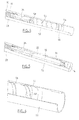
- the probe body 28 carries at its end a cylindrical hollow tube 52.
- This tube has an inside diameter corresponding to the outside diameter of the capsule 10 (cf. Figure 5 ) and a length to accommodate it entirely, including the anchoring screw 14, inside the hollow tube.
- the hollow tube 52 is provided with a helical groove 54 (visible in particular in the enlarged view of the Figure 6 ) formed in the inner surface of the tube opening into a circular internal recess.
- the coupling finger 20 slides in this helical groove when the pin of the connector is actuated (pin driven technique ), thus driving the screw 14 out of the hollow tube 52.
- the helicoidal spring guide is shown at 56. It is in the form of a flat ribbon 56 of elastically deformable material in compression, with a proximal end 58 secured to the endpiece 34 and a distal end hbre 60 present on its last turn a step of slightly increased size, in the same way as in the previous embodiment.
- the direction of the pitch of the helical groove 54 is the same as that of the anchoring screw 14 (not right), however the pitch of the flat spring 56 forming a healcale guide is a reverse pitch (not left).
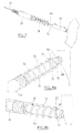
- the Figure 7 illustrates an advantageous improvement that can be implemented with one or other of the two embodiments described above. and which is designed to allow a repositioning in the short or medium term of the capsule 10 after its release.
- connection between the probe body 28 and the capsule 10, which are dissociable elements, is doubled by a "breadcrumb" 62 connected to the capsule 10 on the distal side and protruding from the probe body on the proximal side (not shown)
- the proper functioning of the latter is tested, including the establishment of the wireless communication fingered the capsule and the remote master device.
- the probe body 28 is completely removed, and excess length of the breadcrumb 62 is allowed to protrude outside the patient, under the dressing.
- the breadcrumb trail allows the capsule to be recovered if it moves in the acute phase, simply by pulling on the wire.
- the breadcrumb wire carries a region 64 of resorbable material at the place of its reason with the capsule 10. for example over a length of 3 to 5 mm, which allows the final removal of the breadcrumb by a simple pull for example one month after the intervention.
- All or part of the breadcrumb 62 may contain a DSP-type active agent or a surface treatment to stop any propagation of infection between the emerging part (under the dressing) and the part introduced into the venous network.
- the breadcrumb can be colored in different colors for each of the implanted capsules, so as to identify more tapping the capsule concerned (atrial, ventricle, ..) in the event of a reoperation.
- the technique of the invention thus provides a double safety during the release of the capsule: the first security results from the release system for detecting any coring of the heart wall, the second guarantees the practitioner the possibility, even after dropping, of recover in the medium term the capsule in case of difficulty by medium or breadcrumb.
- the Figures 8a and 8b illustrate in two different orientations, an improvement providing a reversibility of the installation of the capsule, so that it can again be coupled again the probe body 28 to the capsule 10 so as to unscrew it to remove and reimplant it possibly in another site,
- the in situ reset of the spring propeller 36 requires fitting on the capsule 10 in the distal region a compression ramp 66 extending the distal coupling finger 20
- This ramp has, as illustrated in Figures Sa and 8b, a helical shape 68 extending along the length of a turn fraction, with a right-hand pitch (opposite that of the spring-propeller 36) and having a proximal flank 70 against which I will slide the free end 72 of the spring propeller 36.
- the compression ramp 66 is made necessary by the fact that, in the absence of this ramp, the uncompressed spring propeller 36 at the time of docking with the capsule 10 and screwing on the proximal coupling finger 22, would engage the distal coupling finger 20 by its distal side, so that the disengagement mechanism described above would fontionait more.
Landscapes
- Health & Medical Sciences (AREA)
- Heart & Thoracic Surgery (AREA)
- Animal Behavior & Ethology (AREA)
- Nuclear Medicine, Radiotherapy & Molecular Imaging (AREA)
- Radiology & Medical Imaging (AREA)
- Life Sciences & Earth Sciences (AREA)
- Biomedical Technology (AREA)
- General Health & Medical Sciences (AREA)
- Public Health (AREA)
- Veterinary Medicine (AREA)
- Engineering & Computer Science (AREA)
- Cardiology (AREA)
- Prostheses (AREA)
- Measurement And Recording Of Electrical Phenomena And Electrical Characteristics Of The Living Body (AREA)
Abstract
Description
L'invention concerne les "dispositifs médicaux implantables actifs" tels que définis par la directive 90/385/CEE du 20 juin 1990 du Conseil des communautés européennes; plus les implants permettant de surveiller en continu le rythme cardiaque et délivrer si nécessaire au coeur des impulsions électriques de stimulation, de de cardioversion et/ou de défibrillation en cas de trouble du rythme détecté par le dispositif,The invention relates to "active implantable medical devices" as defined by Council Directive 90/385 / EEC of 20 June 1990; plus implants for continuous monitoring of the heart rate and deliver if necessary heart electrical pacing pulses, cardioversion and / or defibrillation in case of rhythm disorder detected by the device,
Elle concerne plus particuliérement ceux de ces dispositifs qui mettent en oeuvre des capsules autonomes implantées dans une cavité cardiaque, ventricule ou oreillette, et qui sont dépourvues de toute liaison physique à un dispositif principal implanté (tel qu'un boîtier de générateur d'impulsions de stimulation) ou non implanté (périphérique externe tel que programmateur ou dispositif de monitoring pour le suivi à distance du patient).It relates more particularly to those devices which use autonomous capsules implanted in a heart chamber, ventricle or atrium, and which are devoid of any physical connection to an implanted main device (such as a pulse generator box of stimulation) or not implanted (external device such as programmer or monitoring device for remote monitoring of the patient).
Ces capsules autonomes sont dénommées pour cette raison "capsules leadless", pour les distinguer des électrodes ou des capteurs disposés à l'extrémité distale d'une sonde (lead), cette sonde étant parcourue sur toute sa longueur par un ou plusieurs conducteurs reliant par voie galvanique l'électrode ou le capteur à un générateur connecté à l'extrémité opposée, proximale, de la sonde.These autonomous capsules are named for this reason " leadless capsules", to distinguish them from the electrodes or sensors arranged at the distal end of a probe ( lead ), this probe being traversed along its length by one or more connecting conductors by Galvanically route the electrode or sensor to a generator connected to the opposite, proximal end of the probe.
De telles capsules leadless sont par exemple décrites dans les
La fixation à la paroi cardiaque de ces capsules se fait généralement au moyen d'une vis d'ancrage hélicoïdale saillante, prolongeant axialement le corps cylindrique de la capsule et destinée à pénétrer dans le tissu cardiaque par vissage au site d'implantation.The attachment to the cardiac wall of these capsules is generally done by means of a protruding helical anchoring screw, axially extending the cylindrical body of the capsule and intended to penetrate into the heart tissue by screwing to the implantation site.
Bien entendu, pour permettre l'échange de données avec un dispositif distant, ces capsules incorporent des moyens émetteurs/récepteurs de communication sans fil avec ce dispositif maître distantOf course, to enable the exchange of data with a remote device, these capsules incorporate wireless communication transmitter / receiver means with this remote master device
La capsule peut également incorporer un capteur permettant de mesurer localement la valeur d'un paramètre tel que le niveau d'oxygène dans le sang, l'accélération de la paroi cardiaque, etc. Ces capsules peuvent être également des capsules de détection/stimulation composant des moyens pour recueillir des potentiel de dépolarisation du myocarde, et/ou pour appliquer des impulsons de stimulation au site où est implantée la capsule. La capsule porte alors une électrode approprièe, qui peut être notamment constituée par une partie active de la vis d'ancrage La présente invention concerne plus précisément la délivrance des capsules leadless, c'est-à-dire leur mise en place au site d'implantation choisi. L'invention n'est pas limitée à un type particulier de capsule, et elle est applicable indifféremment à tout type de capsule leadless, quelle que soit sa destination fonctionnelle.The capsule can also incorporate a sensor for locally measuring the value of a parameter such as the level of oxygen in the blood, the acceleration of the heart wall, etc. These capsules may also be detection / stimulation capsules comprising means for collecting myocardial depolarization potential, and / or for apply stimulation pulses to the site where the capsule is implanted. The capsule then carries a suitable electrode, which may in particular be constituted by an active portion of the anchor screw. The present invention relates more specifically to the delivery of the leadless capsules , that is to say their placement at the site of chosen implantation. The invention is not limited to a particular type of capsule, and it is applicable regardless of any type of leadless capsule, regardless of its functional purpose.
De façon générale, les capsules leadless peuvent être des capsules épicardiques, fixées à la paroi extérieure du coeur, ou bien des capsules en docavitaires, fixées à la paroi intérieure d'une cavité ventriculaire ou auriculaire.In general, the leadless capsules may be epicardial capsules attached to the outer wall of the heart, or capsules in docavitaries, attached to the inner wall of a ventricular or atrial cavity.
Dans le cas des capsule endocavitaires, les contraintes d'implantation sont accrues du fait de la voie d'approche, qui implique de passer par le réseau veineux périphérique puis de diriger sous amplificateur de brillance la capsule vers le site d'implantation choisi, de façon à la fois précise et parfaitement sécurisée. Ce n'est qu'une fois le site atteint et la capsule ancrée dans la paroi que l'opérateur pourra procéder au "largage" de cette capsule, c'est-à-dire à sa désolidarisation d'avec l'accessoire de pose.In the case of endocardial capsules, the implantation constraints are increased because of the approach pathway, which involves passing through the peripheral venous network and then directing the capsule to the chosen implantation site, under a brightness amplifier. a way that is both precise and perfectly secure. It is only once the site is reached and the capsule anchored in the wall that the operator can proceed to the "release" of this capsule, that is to say, its disengagement from the installation accessory .
Le
L'acceptation par les praticiens de la technique des capsules leadless endocavitaires repose sur la possibilitè de proposer un système de délivrance qui soit capable de sécuriser la pose de ces capsules en répondant à l'ensemble des contraintes suivantes:
- procédure proche de la pratique courante, qui fasse appel à des gestes bien connus et maîtrisés des praticiens: ponction sous-claviére, insertion et manipulation d'un cathéter via des mandrins préformés pendant la phase d'approche du site d'implantation choisi, fixation de type vis ou barbe, etc. ;
- environnement standard du bloc opératoire ;
- limilation des risques de "carottage" des tissus du fait d'un vissage excessif qui pourrait endommager la paroi ou, pire, la perforer (notamment dans le cas de l'implantation dans une paroi mince que le septum interauriculaire) ;
- possibilité de retrait et/ou de repositionnement post-opératoire en cas de problème, même après largage de la capsule ;
- limitation des conséquences d'une migration de la capsule en cas de déplacement de celle-ci en phase aigüe pendant l'intervention ;
- certitude d'une bonne fixation de la capsule avant retrait des accessoires de pose - celle contrainte étant la plus critique de toutes.
- a procedure that is close to current practice and which uses well-known and well-known procedures by practitioners: subclavian puncture, insertion and manipulation of a catheter via preformed mandrels during the approach phase of the chosen implantation site, fixation screw or beard type, etc. ;
- standard operating room environment;
- Limiting the risk of "coring" the tissues due to excessive screwing that could damage the wall or, worse, perforate it (especially in the case of implantation in a thin wall than the atrial septum);
- possibility of removal and / or post-operative repositioning in the event of a problem, even after the capsule has been dropped;
- limitation of the consequences of a migration of the capsule in case of displacement of the latter during the acute phase;
- certainty of a good fixation of the capsule before removal of the installation accessories - the constraint being the most critical of all.
L'invention propose à cet effet un ensemble de capsule intracardiaque avec son accessoire d'implantation in situ comportant, de manière en elle-même connue notamment d'après le
De façon caractéristique de l'invention, l'accessoire d'implantation comprend un corps de sonde avec une gaine en matériau déformable portant côté distal un guide hélicoïdal formant lesdits moyens découplables de support, de guidage et d'entraînement en rotation de la capsule. Le guide hélicoïdal prolonge axialement le corps de sonde et est solidaire de celui-ci en rotation et en translation, le diamètre intérieur du guide hélicoïdal est homologue du diamètre extérieur du corps cylindrique de la capsule de façon a pouvoir loger celle-ci à l'intérieur, le(s) doigt(s) de couplage faisant saillie entre les spires du guide hélicoidal, et le sens du guide hélicoidal est inverse de celui de la vis d'ancrage.In a characteristic manner of the invention, the implantation accessory comprises a probe body with a sheath of deformable material bearing on the distal side a helical guide forming said detachable means for supporting, guiding and driving in rotation of the capsule. The helical guide axially extends the probe body and is integral therewith in rotation and in translation, the inner diameter of the helical guide is homologous to the outer diameter of the cylindrical body of the capsule so as to accommodate it to the interior, the coupling finger (s) protruding between the turns of the helical guide, and the direction of the helical guide is opposite that of the anchor screw.
La capsule compose de préférence deux doigts de couplage, l'un en partie distale et l'autre en partie proximale,The capsule preferably consists of two coupling fingers, one in the distal portion and the other in the proximal portion,
Dans un premier mode de réalisation, le guide hélicoïdal est une hélice saillante prolongeant axialement l'extrémité distale du corps de sonde, notamment une hélice élastiquement compressible en direction axiale et dont le pas d'hélice est augmenté dans sa partie d'extrémité distale libre. De préférence, la capsule comportant deux doigts de couplage, l'un en partie distale et l'autre en partie proximale, l'écartement en direction axiale de ces deux doigts de couplage est choisi, de manière à procurer une compression de l'hélice lorsque le corps cylindrique de la capsule est complètement logé à l'intérieur du guide hélicoïdal.In a first embodiment, the helical guide is a protruding helix axially extending the distal end of the probe body, in particular an elastically compressible helix in the axial direction and whose helical pitch is increased in its free distal end portion. . Preferably, the capsule comprising two coupling fingers, one in distal part and the other in the proximal part, the axial spacing of these two coupling fingers is chosen, so as to provide a compression of the helix when the cylindrical body of the capsule is completely housed inside the helical guide.
Avantageusement, lorsque le corps de la capsule est complètement logé à l'intérieur du guide hélicoidal, cet ensemble comprend un enrobage soluble de protection englobant la capsule munie de sa vis d'ancrage avec le guide hélicoïdal.Advantageously, when the body of the capsule is completely housed inside the helical guide, this set comprises a soluble protection coating including the capsule provided with its anchor screw with the helical guide.
La capsule peut comprendre en outre une rampe de réarmement prolongeant le doigt de couplage situé en partie distale, cette rampe formant une fraction de filet hélicoïdal avec un sens d'hèlice inverse de celui du guide hélicoidal, et étant apte à venir en contact sur son flanc proximal avec l'extrémitè libre du guide hélicoïdal.The capsule may furthermore comprise a resetting ramp extending the coupling finger located in the distal portion, this ramp forming a fraction of a helical thread with a direction of transmission opposite to that of the helical guide, and being able to come into contact with its proximal flank with the free end of the helical guide.
Dans un deuxième mode de réalisation, l'extrèmité distale du corps de sonde porte un tube creux cylindrique s'étendant axialement et formant un logement apte à contenir la capsule, le guide hélicoïdal étant une rainure hélicoïdale formée dans la surface intérieure de ce logement, et il est prevu des moyens pour déployer la vis d'ancrage par un entraînement de type pin-driven.In a second embodiment, the distal end of the probe body carries a cylindrical hollow tube extending axially and forming a housing adapted to contain the capsule, the helical guide being a helical groove formed in the inner surface of this housing, and means are provided for deploying the anchor screw by a pin-driven drive .
De préférence, le pas du guide hélicoïdal est augmenté dans sa partie d'extrémité distale libre.Preferably, the pitch of the helical guide is increased in its free distal end portion.
De préférence également, la capsule comportant deux doigts de couplage, l'un en partie distale et l'autre en partie proximale, l'écartement en direction axiale de ces deux doigts de couplage est choisi de manière à procurer une compression du ressort lorsque le corps cylindrique de la capsule est complètement logé à l'intérieur du guide hélicoïdal.Also preferably, the capsule having two coupling fingers, one in the distal portion and the other in the proximal portion, the axial spacing of these two coupling fingers is selected so as to provide compression of the spring when the cylindrical body of the capsule is completely housed inside the helical guide.
De façon gènèrale, l'ensemble peut comprendre en outre un fil souple disposé dans une lumière du corps de sonde et reliant la capsule à l'extrémité proximale du corps de sonde sur toute la longueur de celui-ci, ce fil comprenant au voisinage du point de liaison à la capsule une portion réalisée en un matériau résorbable.In general, the assembly may further comprise a flexible wire disposed in a lumen of the probe body and connecting the capsule to the end proximal of the probe body over the entire length thereof, the wire comprising in the vicinity of the point of connection to the capsule a portion made of a resorbable material.
La capsule peut notamment être une capsule de détection/stimulation comportant des moyens de recueil de potentiels de dépolarisation et/ou d'application d'impulsions de stimulation couplés à au moins une électrode portée par la capsule, notamment une électrode constituée par une partie active de la vis d'ancrage, ainsi que des moyens émetteurs/récepteurs de communication sans fil avec un dispositif maître distant.The capsule may in particular be a detection / stimulation capsule comprising means for collecting depolarization potentials and / or for applying stimulation pulses coupled to at least one electrode carried by the capsule, in particular an electrode consisting of an active part anchor screw, and wireless communication transmitter / receiver means with a remote master device.
On va maintenant décrire un exemple de mise en oeuvre de l'invention, en référence aux dessins annexés où les mêmes références numériques désignent d'une figure à l'autre des éléments identiques ou fonctionnellement semblables.
- La
Figure 1 est une vue perspective montrant la capsule autonome et l'accessoire d'implantation dans une configuration où ces deux éléments sont séparés. - La
Figure 2 est homologue de laFigure 1 , dans une configuration où la capsule autonome a été accouplée à l'accessoire d'implantation, juste avant la phase d'implantation. - La
Figure 3 est homologue de laFigure 2 , dans une configuration en cour d'implantation de la capsule dans la paroi de la cavité du coeur, montrant les différentes sollicitations réciproques exercées entre la capsule et l'accessoire d'implantation. - La
Figure 4 illustre, en perspective et en coupe, un second mode de rèalisation de l'accessoire d'implantation, avant mise en place de la capsule. - La
Figure 5 est homologue de laFigure 4 , avec la capsule logée dans l'accessoire d'implantation. - La
Figure 6 est une vue agrandie de la partie distale de l'accessoire d'implantation illustréFigure 4 . - La
Figure 7 illustre une variante perfectionnée mettant en oeuvre un dispositif de type fil d'Ariane. - Les
Figures 8a et 8b sont des vues perspectives, selon deux orientations différentes, d'un perfectionnement au mode de réalisation procurant une réversibilité de la pose de la capsule, afin de pouvoir si nécessaire dévisser celle-ci pour la retirer et la réimplanter en un autre site.
- The
Figure 1 is a perspective view showing the autonomous capsule and the attachment accessory in a configuration where these two elements are separated. - The
Figure 2 is counterpart of theFigure 1 in a configuration where the autonomous capsule has been coupled to the implantation accessory, just before the implantation phase. - The
Figure 3 is counterpart of theFigure 2 , in a configuration in the course of implantation of the capsule in the wall of the heart cavity, showing the different reciprocal stresses exerted between the capsule and the implantation accessory. - The
Figure 4 illustrates, in perspective and in section, a second embodiment of the implantation accessory, before introduction of the capsule. - The
Figure 5 is counterpart of theFigure 4 , with the capsule housed in the attachment accessory. - The
Figure 6 is an enlarged view of the distal portion of the illustrated attachment accessoryFigure 4 . - The
Figure 7 illustrates an improved variant implementing a breadcrumb device. - The
Figures 8a and 8b are perspective views, according to two different orientations, of an improvement to the embodiment providing a reversibility of the installation of the capsule, so as to be able if necessary to unscrew it to remove and reimplant to another site.
On va maintenant décrire un exemple de réalisation de S'invention.An exemplary embodiment of the invention will now be described.
Sur la
La vis d'ancrage 14 peut être une vis électriquement active, c'est-à-dire jouant, au moins à son extrémité distal, le rôle d'électrode de détection et/ou de stimulation, ou bien une vis passive ne servant qu'à l'ancrage du corps tubulaire 12 dans la paroi de la cavité cardiaque.The anchoring
Le corps tubulaire 12 inclut divers moyens et circuits d'alimentation, de traitement du signal et de communication sans fil pour permettre l'échange de signaux avec un dispositif maître distant, implanté ou non. Ces aspects sont en eux-mêmes connus et, comme ils ne font pas partie de l'invention, ils ne seront pas dècrits ; on pourra se référer aux diverses publications citées en début de la présente description pour plus de détails à ce sujet.The
Le corps tubulaire 12 est cylindrique et, de façon caractéristique de l'invention, porte au moins un doigt de couplage en forme de protubérance axialement savante, dont la fonction sera explicitée plus bas. Dans l'exemple illustré, qui correspond à une configuration avantageuse, la capsule comprend deux de ces doigts de couplage, situés l'un 20 côté distal, l'autre 22 côté proximal, avec un écartement en direction axiale présentant une valeur prédéterminée (on expliquera plus bas l'importance de cette caractéristique). La forme de ces doigts de couplage 20, 22 peut être adaptée de manière à leur donner un profil adouci, atraumatique.The
Le corps tubulaire 12 présente une longueur de l'ordre de 5 a 10 mm et un diamètre de l'ordre de 1 à 2 mm (6 French). L'extrémité proximale 24 de la capsule 10 peut être arrondie ou en forme d'ogive pour, d'une part, la rendre atraumatique et, d'autre part, faciliter son couplage avec l'accessoire de pose.The
Les
Cet accessoire comprend, essentiellement, un corps 28 structurellement semblable à un corps de sonde de type monopolaire, c'est-à-dire avec une structure en elle-même connue comportant sur toute sa longueur un conducteur spiralé 30 enrobé d'une gaine 32. La gaine 32 est général ment en polyuréthanne, pour limiter les frottements lorsque le corps de sonde est introduit dans un cathéter-guide ou dans le réseau veineux, et pour procurer une meilleure sensibilité et une meilleure transmission du couple de torsion. On notera que, dans le cas de l'invention, le conducteur 30 n'a pas de fonction électrique, il contribue seulement au comportement mécanique du corps de sonde 28 en assurant en outre la radio-opacité de celui-ci.This accessory comprises, essentially, a
L'ensemble conducteur 30/gaine 32 procure au corps de sonde 28 une rigidité en torsion suffisante pour pouvoir transmettre un couple de torsion depuis son extrémité proximale jusqu'à son extrèmité distale afin d'entraîner en rotation cette extrémité distale. Il est toutefois possible, en variante ou en complément, d'introduire dans la lumière du corps de sonde 28 un mandrin de vissage spécifique, notamment lorsque la gaine 32 ne présente pas une rigidité en torsion sufl°isante pour entraïner directement l'extrémité distale du corps de sonde depuis l'extrémité proximale L'extrémité distale du corps de sonde 28 est pourvue d'un embout 34 auquel est solidarisé un guide hélicoïdal 36 formé, dans ce mode de réalisation, d'une hélice 38 réalisée dans un matériau élastique (par exemple un alliage de type M35N ou rutinol), permettant de rendre l'hélice 38 compressible en direction axiale à la manière d'un ressort de compression hélicoïdal.The
De façon caractéristique, cette hélice-ressort 38 présente un pas inversé par rapport au pas de la vis d'ancrage hélicoïdale 16 de la capsule, par exemple un pas à gauche si la vis d'ancrage présente un pas à droite, En outre, l'hélice-ressort 38 présente à son extrémité distale libre un pas légèrement allongé, par exemple sur la spire la plus distale 40Characteristically, this helix-
A !'extrémité opposée, l'hélice-ressort 38 est reliée à l'embout 34 par une partie de transition 42 présentant une certaine souplesse en flexion, par exemple une partie 42 formée de spires jointives en l'absence de sollicitation de l'hèlice-ressort 38,At the opposite end, the spring-
Lors de la fabrication, le corps 12 de la capsule 10 est vissé dans l'hélice-ressort 38, aboutissant ainsi à la configuration illustrée
L'ensemble de la partie distale est alors recouvert d'un revêtement soluble 44, par exemple de polyéthyléne glycol (PEG), Cette protection a pour but de protéger la vis d'ancrage 14, l'hélice-ressort 38 et les tissus environnants lors de l'insertion de l'ensemble dans le réseau veineux, Pour limiter le temps de dissolution, il est possible de prévoir pour ce revêtement un profil étagé, évitant une surépaisseur du revêtement autour de la vis d'ancrage 14.The entire distal portion is then covered with a soluble coating 44, for example polyethylene glycol (PEG), This protection is intended to protect the
Lors de l'implantation, l'ensemble est introduit jusqu'à la cavité selon une procédure classique, Le corps de sonde 28 étant de construction standard. le praticien retrouvera les sensations classiques de couple. de flexibilité, de glissement, etc.During implantation, the assembly is introduced to the cavity according to a conventional procedure, the
Une fois la protection PEG 44 complètement dissoute, le médecin positionne l'extrémité de la vis d'ancrage 14 contre la paroi cardiaque, et commence le vissage, par rotation dans le sens horaire (correspondant au pas à droite de la vis d'ancrage 14).Once the PEG 44 protection is completely dissolved, the doctor positions the end of the anchoring
Le couple est transmis depuis l'extrémité proximale du corps de sonde 28 et permet, dans un premier temps, la pénétration de la vis d'ancrage 14 dans le tissu de la paroi 46 de la cavité du coeur. La valeur correspondante du couple permettant cette opération sera désignée Cvissage The torque is transmitted from the proximal end of the
La
Avec une vis d'ancrage d'une sonde standard. si le praticien poursuivait la rotation du corps de sonde et de la vis, le couple augmenterait et dépasserait une limite Ccarotiage. la vis d'ancrage 14 risquant alors de déchirer localement les tissus sous l'effet de la rotation de la vis sans avance de celle-ci, jusqu'à provoquer une lacération des tissus et. a l'extrême, une perforation de la paroi avec risque de tamponnade.With an anchor screw of a standard probe. if the practitioner continued the rotation of the probe body and the screw, the torque would increase and exceed a limit C carotiage . the anchoring
Tel n'est pas le cas avec le dispositif proposé par l'invention : le médecin peut en effet poursuivre sans risque la rotation, toujours dans le sens horaire, du corps de sonde 28 car le couple supplèmentaire apparaissant du fait de la réaction de la vis 14 ancrée dans les tissus est absorbé par la liaison entre l'hélice-ressort 38 et la capsule 10. Plus précisèment. l'élasticité en compression de l'hélice-ressort 38 est choisie de manière à dèfinir un couple de glissement Cgilssement inférieur à la limite Ccarottage du carottage, de sorte que lorsque le couple Cglissement est atteint, la poursuite de la rotation du corps de sonde 28 dans le sens horaire amorce la rotation de autour de la capsule 10, grâce au pas inversé de l'hèlice-ressort 38, Cette dernière se dégage alors progressivement de la capsule 10 par dévissage (du fait de l'inversion du sens du pas). On notera que la dimension de pas légèrement accrue de la dernière spire 40 permet de générer une compression des spires de l'hélice-ressort 38 entre les deux doigts de couplage 20 et 22 (flèches 48) et donc une force d'appui croissante sur ces doigts de couplage, ceci jusqu'à la libération du doigt distal 20, situation qui définit un couple de débrayage Cdébrayage permettant alors le découplage de la capsule 10 et du corps de sonde 28 (flèche 50).This is not the case with the device proposed by the invention: the doctor can indeed continue without risk the rotation, always in the clockwise direction, of the
La géométrie des différents éléments qui assurent cette interaction. ainsi que l'élasticité en compression de l'hélice-ressort, sont choisis de manière à vérifier la relation: ![]()
- Cvissage désignant le couple de vissage dans les tissus.
- Cglissement désignant le couple supplémentaire absorbé par la liaison entre l'hélice et la capsule,
- Cdebravage dèsignant le couple atteint à la libération du doigt distal , et
- Ccarottage désignant le couple limite au-delà duquel la rotation de la vis d'ancrage risque provoquer un déchirement des tissus de la paroi
- C screwing designating the tightening torque in the tissues.
- C slip designating the additional torque absorbed by the connection between the helix and the capsule,
- C unraveling the torque reached at the release of the distal finger, and
- C coring designating the limit torque beyond which rotation of the anchor screw may cause tearing of the wall fabric
On notera que le système de dèbrayage, situé à proximité de la vis d'ancrage 14 et donc en partie d'extrémité distale de l'ensemble, n'est pas dépendant du comportement en torsion du corps de sonde 28, à la différence par exemple d'un système de limitation de couple qui serait placé côté proximal.It will be noted that the disengaging system, located near the anchoring
D'autre part, on notera que lors du débrayage la longueur comprimée de l'hélice-ressort 36 est maximale, ce qui permet de garantir une reproductibilité maximale du couple de débrayage.On the other hand, it will be noted that during disengagement the compressed length of the
Le mécanisme que l'on vient de décrire permet d'absorber la montée progressive du couple du fait de la réaction de la vis d'ancrage 14 une fois celle-ci complètement introduite dans la paroi de la cavité cardiaque, avec un double bénéfice :
- certitude du vissage complet de la
capsule 10, et - suppression de tout risque de tamponnade.
- certainty of the complete screwing of the
capsule 10, and - removal of any risk of tamponade.
L'ensemble de l'opération est transparente pour le médecin, dans la mesure où un simple et unique mouvement de rotation horaire depuis l'extrémité proximale du corps de sonde 28 permet d'assurer à la fois la fixation complète de la capsule et son largage.The entire operation is transparent to the doctor, insofar as a simple and single clockwise movement from the proximal end of the
On va maintenant décrire en référence aux
En particulier, ce second mode de réalisation est bien adapté aux cas où le corps de sonde 28 est un système standard de type dit pin driven, où le praticien maintient d'une main l'extrémité proximale du corps de sonde et de l'autre main fait tourner, directement ou par l'intermédiaire d'un outil, la fiche (pin) dépassant de cette extrémité proximale. Concrètement. la fiche est solidaire du conducteur axial 30 s'étendant à l'intèrieur du corps de sonde ce conducteur étant alors libre en rotation par rapport à la gaine 32 et étant relié à son extrémité distale à l'embout 34.In particular, this second embodiment is well suited to cases where the
Ce second mode de réalisation permet par ailleurs d'évier le recours d'un revêtement en PEG soluble pour la protection de la vis, dans la mesure où cette dernière pourra être rètractée à intérieur d'un tube protecteur pendant toute la durée de la descente intraveineuse.This second embodiment also allows the use of a soluble PEG coating for the protection of the screw, insofar as the latter can be retracted inside a protective tube for the duration of the descent. intravenous.
Plus précisément, le corps de sonde 28 porte à son extrémité un tube creux cylindrique 52, Ce tube présente un diamètre intérieur correspondant au diamètre extérieur de la capsule 10 (cf
Le tube creux 52 est muni d'une rainure hélicoïdale 54 (visible notamment sur la vue agrandie de la
Le guide hélicoïdal formant ressort est représenté en 56. Il se présente sous forme d'un ruban plat 56 en matériau élastiquement déformable en compression, avec une extrémité proximale 58 solidaire de l'embout 34 et une extrémité distale hbre 60 présente sur sa dernière spire un pas de dimension légèrement accrue, de la même façon que dans le mode de réalisation précédent.The helicoidal spring guide is shown at 56. It is in the form of a
Le sens du pas de la rainure hélicoïdale 54 est le même que celui de la vis d'ancrage 14 (pas à droite), en revanche le pas du ressort plat 56 formant guide héhcoïdal est un pas inversé (pas à gauche).The direction of the pitch of the helical groove 54 is the same as that of the anchoring screw 14 (not right), however the pitch of the
Avec cette configuration, la rotation de la broche du connecteur côté proximal du corps de sonde 28 entraînera une rotation de l'embout 34 et simultanément de l'ensemble constitué par la capsule 10 et le ressort 56 dans un mouvement hélicoïdal vers l'avant par rapport au tube 52, entraînant ainsi progressivement le déploiement de la vis 14 hors du tube 52, puis le vissage de celle-ci dans la paroi de la cavité du coeur, jusqu'à ce que la face avant de la capsule vienne en appui contre cette paroi.With this configuration, the rotation of the pin of the proximal connector of the
La poursuite du vissage provoque, par l'action du ressort hélicoïdal 56 sur les doigts de couplage 20 et 22, la séparation de la capsule 10 d'avec le ressort 56, permettant le largage progressif de cette dernière avec la fonction de débrayage décrite plus haut à propos du premier mode de réalisation, qui empêche tout endommagement des tissus par la vis d'ancrage. La cinématique et les contraintes Sur les valeurs de couple exposées en détail à propos du premier mode de réalisation sont applicables de la même façon à ce second mode de rèalisation.The continuation of the screwing causes, by the action of the
La
Dans ce perfectionnement la liaison entre le corps de sonde 28 et la capsule 10, qui sont des éléments dissociables, est doublée par un "fil d'Ariane" 62 relié à la capsule 10 du côté distal et dépassant du corps de sonde du côté proximal (non représenté).In this improvement the connection between the
Une fois la capsule 10 implantée, le bon fonctionnement de celle-ci est testé, notamment le bon établissement de la communication sans fil enture la capsule et le dispositif maître distant. Lorsque la capsule est correctement fixée, le corps de sonde 28 est complètement retiré, et un surplus de longueur du fil d'Ariane 62 est laissé de manière a dépasser en dehors du patient, sous le pansement.Once the
A ce stade, le fil d'Ariane permet de récupérer la capsule en cas de déplacement en phase aigüe, par simple traction sur le fil,At this stage, the breadcrumb trail allows the capsule to be recovered if it moves in the acute phase, simply by pulling on the wire.
Le fil d'Ariane porte une région 64 en matériau résorbable à l'endroit de sa raison avec la capsule 10. par exemple sur une longueur de 3 à 5 mm, ce qui permet le retrait définitif du fil d'Ariane par une simple traction, par exemple un mois après l'intervention.The breadcrumb wire carries a
Tout ou partie du fil d'Ariane 62 peut contenir un agent actif de type DSP ou un traitement de surface permettant de stopper toute propagation d'infection entre la partie émergeante (sous le pansement) et la partie introduite dans le réseau veineux.All or part of the breadcrumb 62 may contain a DSP-type active agent or a surface treatment to stop any propagation of infection between the emerging part (under the dressing) and the part introduced into the venous network.
En cas de test négatif juste après l'implantation ou en cas de dysfonctionnement ultérieur, il est possible de réengager l'hèlice-ressort 36 sur la capsule grâce au guidage du fil d'Ariane 62 et à la forme arrondie de la partie arriére 24 de la capsule 10. Cette dernière peut alors être dévissée de la paroi par une rotation du corps de sonde 28 dans le sens antihoraire, puis replacée sur un autre site par le même principe que ce qui a été décrit plus haut, par une rotation dans le sens horaire.In the event of a negative test just after the implantation or in the event of a subsequent malfunction, it is possible to reengage the spring-
Le fil d'Ariane peut être coloré de couleurs différentes pour chacune des capsules implantées, de manière à identifier plus tapement la capsule concernée (auriculaire, ventrlculaire, ..) dans l'éventualité d'une réintervention.The breadcrumb can be colored in different colors for each of the implanted capsules, so as to identify more tapping the capsule concerned (atrial, ventricle, ..) in the event of a reoperation.
La technique de l'invention procure donc une double sécurité lors du largage de la capsule : la première sécurité résulte du système de débrayage permettant d'épier tout carottage de la paroi cardiaque, le second garantit au praticien la possibilitè, même après largage, de récupérer à moyen terme la capsule en cas de difficulté au moyen ou fil d'Ariane. Les
Au moment de la remise en place du corps de sonde sur la capsule, le réarmement in situ de l'hélice-ressort 36 nécessite d'aménager sur la capsule 10 dans la région distale une rampe de compression 66 prolongeant le doigt de couplage distal 20. Cette rampe présente, comme illustré sur les Figures Sa et 8b, une forme hélicoïdale 68 s'étendant sur la longueur d'une fraction de spire, avec un pas à droite (inverse de celui de l'hélice-ressort 36) et présentant un flanc proximal 70 contre lequel viendra glisser J'extrémité libre 72 de l'hélice-ressort 36. La rampe de compression 66 est rendue nécessaire par le fait que, en l'absence de cette rampe, l'hélice-ressort 36 non compressée au moment de l'accostage avec la capsule 10 puis du vissage sur le doigt de couplage proximal 22, viendrait engager le doigt de couplage distal 20 par son côté distal, de sorte que le mécanisme de débrayage décrit plus haut ne fontionnerait plus.At the time of the repositioning of the probe body on the capsule, the in situ reset of the
Claims (15)
cette capsule comportant un corps tubulaire (12) cylindrique pourvu à l'une de ses extrémités d'une vis d'ancrage (14) hélicoïdale saillante prolongeant axialement le corps cylindrique, et apte à pénétrer dans le tissu de la paroi (46) d'une cavité du coeur.
caractérisée en ce qu'elle comporte au moins un doigt de couplage (20, 22) solidaire du corps cylindrique et faisant saillie radialement vers l'extérieur.An intracardiac capsule (10) for an assembly according to one of claims 1 to 13,
this capsule comprising a cylindrical tubular body (12) provided at one of its ends with a protruding helical anchoring screw (14) axially extending the cylindrical body, and able to penetrate into the fabric of the wall (46) of a cavity of the heart.
characterized in that it comprises at least one coupling pin (20, 22) integral with the cylindrical body and projecting radially outwards.
cet accessoire (26) comportant des moyens découplables de support et de guidage d'une capsule jusqu'au site d'implantation, et d'entraînement en rotation de cette capsule pour permettre l'entraînement simultané de la vis et son ancrage par pénétration dans la de la cavité du coeur, caractérisé en ce qu'il comprend un corps de sonde (23) avec une gaine (30, 32) en matériau déformable portant côté distal un guide hélicoidal (36 ; 52) formant lesdits moyens dècouplables de support, de guidage et d'entraînement en rotation de la capsule, où :
this accessory (26) comprising decoupling means for supporting and guiding a capsule to the implantation site, and rotational drive of this capsule to allow simultaneous driving of the screw and its anchoring by penetration into the cavity of the heart, characterized in that it comprises a probe body (23) with a sheath (30, 32) of deformable material bearing a distal side a helical guide (36; 52) forming said removable means of support, for guiding and rotating the capsule, where:
Applications Claiming Priority (1)
| Application Number | Priority Date | Filing Date | Title |
|---|---|---|---|
| FR1054699 | 2010-06-14 |
Publications (2)
| Publication Number | Publication Date |
|---|---|
| EP2394695A1 true EP2394695A1 (en) | 2011-12-14 |
| EP2394695B1 EP2394695B1 (en) | 2012-09-26 |
Family
ID=43502803
Family Applications (1)
| Application Number | Title | Priority Date | Filing Date |
|---|---|---|---|
| EP11157822A Active EP2394695B1 (en) | 2010-06-14 | 2011-03-11 | Standalone intracardiac capsule and implantation accessory |
Country Status (2)
| Country | Link |
|---|---|
| US (2) | US8548605B2 (en) |
| EP (1) | EP2394695B1 (en) |
Cited By (16)
| Publication number | Priority date | Publication date | Assignee | Title |
|---|---|---|---|---|
| EP2719424A1 (en) * | 2012-10-12 | 2014-04-16 | Sorin CRM SAS | Intraseptal probe for left ventricular stimulation |
| EP2818201A1 (en) | 2013-06-24 | 2014-12-31 | Sorin CRM SAS | Intracardiac capsule and accessory for in situ implantation by the femoral route |
| EP2818202A1 (en) | 2013-06-24 | 2014-12-31 | Sorin CRM SAS | Coupling system between a medical device and an accessory for in situ implantation thereof |
| EP2881141A1 (en) | 2013-12-04 | 2015-06-10 | Sorin CRM SAS | Implantable intracardiac capsule on a thin wall, in particular the septal wall |
| EP2929910A1 (en) * | 2014-04-08 | 2015-10-14 | Sorin CRM SAS | Intracardiac capsule and accessory for explanting same |
| EP2959940A1 (en) | 2014-06-25 | 2015-12-30 | Sorin CRM SAS | Implantable capsule with attachment by screwing, in particular an autonomous cardiac stimulation capsule |
| EP2959828A1 (en) | 2014-06-25 | 2015-12-30 | Sorin CRM SAS | Hybrid assembly forming an active implantable medical device |
| EP2959936A1 (en) | 2014-06-25 | 2015-12-30 | Sorin CRM SAS | Implantable capsule with attachment by screwing, in particular an autonomous cardiac stimulation capsule |
| EP3069754A1 (en) | 2015-03-16 | 2016-09-21 | Sorin CRM SAS | In situ implantation accessory for self-contained intracardiac capsule |
| EP3069755A1 (en) | 2015-03-18 | 2016-09-21 | Sorin CRM SAS | Active implantable medical device comprising a connector-free capsule, permanently connected to a microprobe |
| WO2017027770A1 (en) * | 2015-08-12 | 2017-02-16 | Medtronic, Inc. | Epicardial defibrillation lead with side helix fixation and placement thereof |
| EP3173126A1 (en) | 2015-11-27 | 2017-05-31 | Sorin CRM SAS | Implantable capsule, in particular an autonomous cardiac stimulation capsule |
| WO2017158174A1 (en) | 2016-03-18 | 2017-09-21 | Sorin Crm Sas | Active implantable medical device for combined treatment of cardiac rhythm and of respiratory rhythm |
| EP3248649A1 (en) * | 2016-05-24 | 2017-11-29 | Sorin CRM SAS | A torque limiting mechanism between a medical device and its implantation accessory |
| WO2018200479A1 (en) * | 2017-04-25 | 2018-11-01 | Jeffry Melsheimer | Tissue fixation systems |
| US10881868B2 (en) | 2016-05-24 | 2021-01-05 | Sorin Crm Sas | Torque limiting mechanism between a medical device and its implantation accessory |
Families Citing this family (136)
| Publication number | Priority date | Publication date | Assignee | Title |
|---|---|---|---|---|
| ATE531420T1 (en) * | 2009-04-28 | 2011-11-15 | Sorin Crm Sas | INTRACARDIAL SENSOR FOR STIMULATION OR DEFIBRILLATION WITH RETRACTABLE SCREW |
| US9393407B2 (en) | 2012-04-05 | 2016-07-19 | Children's Hospital Los Angeles | Minimally invasive epicardial pacemaker |
| EP2943132B1 (en) * | 2013-01-09 | 2018-03-28 | 4Tech Inc. | Soft tissue anchors |
| US8948883B2 (en) | 2013-04-24 | 2015-02-03 | Medtronic, Inc. | Electrode assemblies and associated fixation members for implantable medical devices |
| WO2014182948A2 (en) * | 2013-05-08 | 2014-11-13 | Children's Hospital Los Angeles | Epicardial lead design |
| US10071243B2 (en) | 2013-07-31 | 2018-09-11 | Medtronic, Inc. | Fixation for implantable medical devices |
| EP3033145B1 (en) | 2013-08-16 | 2021-09-22 | Cardiac Pacemakers, Inc. | Leadless cardiac pacemaker and retrieval device |
| US9393427B2 (en) | 2013-08-16 | 2016-07-19 | Cardiac Pacemakers, Inc. | Leadless cardiac pacemaker with delivery and/or retrieval features |
| US10722723B2 (en) | 2013-08-16 | 2020-07-28 | Cardiac Pacemakers, Inc. | Delivery devices and methods for leadless cardiac devices |
| EP3033146B1 (en) | 2013-08-16 | 2018-03-07 | Cardiac Pacemakers, Inc. | Delivery devices for leadless cardiac devices |
| US10842993B2 (en) | 2013-08-16 | 2020-11-24 | Cardiac Pacemakers, Inc. | Leadless cardiac pacing devices |
| US9480850B2 (en) | 2013-08-16 | 2016-11-01 | Cardiac Pacemakers, Inc. | Leadless cardiac pacemaker and retrieval device |
| BR112016003148B1 (en) | 2013-08-16 | 2021-01-12 | Cardiac Pacemakers, Inc. | non-shunt cardiac pacing devices |
| US9492674B2 (en) | 2013-08-16 | 2016-11-15 | Cardiac Pacemakers, Inc. | Leadless cardiac pacemaker with delivery and/or retrieval features |
| ES2661718T3 (en) | 2014-01-10 | 2018-04-03 | Cardiac Pacemakers, Inc. | Methods and systems to improve communication between medical devices |
| AU2015204701B2 (en) | 2014-01-10 | 2018-03-15 | Cardiac Pacemakers, Inc. | Systems and methods for detecting cardiac arrhythmias |
| WO2015168153A1 (en) | 2014-04-29 | 2015-11-05 | Cardiac Pacemakers, Inc. | Leadless cardiac pacing devices including tissue engagement verification |
| US9795781B2 (en) | 2014-04-29 | 2017-10-24 | Cardiac Pacemakers, Inc. | Leadless cardiac pacemaker with retrieval features |
| US10674928B2 (en) | 2014-07-17 | 2020-06-09 | Medtronic, Inc. | Leadless pacing system including sensing extension |
| US9399140B2 (en) | 2014-07-25 | 2016-07-26 | Medtronic, Inc. | Atrial contraction detection by a ventricular leadless pacing device for atrio-synchronous ventricular pacing |
| WO2016033197A2 (en) | 2014-08-28 | 2016-03-03 | Cardiac Pacemakers, Inc. | Medical device with triggered blanking period |
| US11278720B2 (en) | 2014-10-22 | 2022-03-22 | Cardiac Pacemakers, Inc. | Delivery devices and methods for leadless cardiac devices |
| CN107087399B (en) | 2014-10-22 | 2020-05-12 | 心脏起搏器股份公司 | Delivery device for leadless cardiac devices |
| US9623234B2 (en) | 2014-11-11 | 2017-04-18 | Medtronic, Inc. | Leadless pacing device implantation |
| US9724519B2 (en) | 2014-11-11 | 2017-08-08 | Medtronic, Inc. | Ventricular leadless pacing device mode switching |
| US9492669B2 (en) | 2014-11-11 | 2016-11-15 | Medtronic, Inc. | Mode switching by a ventricular leadless pacing device |
| US9492668B2 (en) | 2014-11-11 | 2016-11-15 | Medtronic, Inc. | Mode switching by a ventricular leadless pacing device |
| WO2016090360A1 (en) | 2014-12-05 | 2016-06-09 | Vquad Medical | Epicardial heart rhythm management devices, systems and methods |
| US9289612B1 (en) | 2014-12-11 | 2016-03-22 | Medtronic Inc. | Coordination of ventricular pacing in a leadless pacing system |
| US10220213B2 (en) | 2015-02-06 | 2019-03-05 | Cardiac Pacemakers, Inc. | Systems and methods for safe delivery of electrical stimulation therapy |
| US9669230B2 (en) | 2015-02-06 | 2017-06-06 | Cardiac Pacemakers, Inc. | Systems and methods for treating cardiac arrhythmias |
| WO2016130477A2 (en) | 2015-02-09 | 2016-08-18 | Cardiac Pacemakers, Inc. | Implantable medical device with radiopaque id tag |
| WO2016137855A1 (en) * | 2015-02-24 | 2016-09-01 | Med-El Elektromedizinische Geraete Gmbh | Active fixation of neural tissue electrodes |
| WO2016141046A1 (en) | 2015-03-04 | 2016-09-09 | Cardiac Pacemakers, Inc. | Systems and methods for treating cardiac arrhythmias |
| US10050700B2 (en) | 2015-03-18 | 2018-08-14 | Cardiac Pacemakers, Inc. | Communications in a medical device system with temporal optimization |
| US10213610B2 (en) | 2015-03-18 | 2019-02-26 | Cardiac Pacemakers, Inc. | Communications in a medical device system with link quality assessment |
| US9993648B2 (en) | 2015-03-27 | 2018-06-12 | Medtronic, Inc. | Medical device delivery system |
| US9610454B2 (en) * | 2015-04-13 | 2017-04-04 | Pacesetter, Inc. | Over torque limiter for leadless implantable medical devices |
| CN108136187B (en) | 2015-08-20 | 2021-06-29 | 心脏起搏器股份公司 | System and method for communication between medical devices |
| CN108136186B (en) | 2015-08-20 | 2021-09-17 | 心脏起搏器股份公司 | System and method for communication between medical devices |
| US9956414B2 (en) | 2015-08-27 | 2018-05-01 | Cardiac Pacemakers, Inc. | Temporal configuration of a motion sensor in an implantable medical device |
| US9968787B2 (en) | 2015-08-27 | 2018-05-15 | Cardiac Pacemakers, Inc. | Spatial configuration of a motion sensor in an implantable medical device |
| CN108136189B (en) | 2015-08-28 | 2021-10-15 | 心脏起搏器股份公司 | System for behavioral response signal detection and therapy delivery |
| WO2017040115A1 (en) | 2015-08-28 | 2017-03-09 | Cardiac Pacemakers, Inc. | System for detecting tamponade |
| US10226631B2 (en) | 2015-08-28 | 2019-03-12 | Cardiac Pacemakers, Inc. | Systems and methods for infarct detection |
| WO2017044389A1 (en) | 2015-09-11 | 2017-03-16 | Cardiac Pacemakers, Inc. | Arrhythmia detection and confirmation |
| US10065041B2 (en) | 2015-10-08 | 2018-09-04 | Cardiac Pacemakers, Inc. | Devices and methods for adjusting pacing rates in an implantable medical device |
| WO2017087675A1 (en) | 2015-11-20 | 2017-05-26 | Cardiac Pacemakers, Inc. | Delivery devices and methods for leadless cardiac devices |
| EP3377173A1 (en) | 2015-11-20 | 2018-09-26 | Cardiac Pacemakers, Inc. | Delivery devices and methods for leadless cardiac devices |
| JP6608063B2 (en) | 2015-12-17 | 2019-11-20 | カーディアック ペースメイカーズ, インコーポレイテッド | Implantable medical device |
| US10905886B2 (en) | 2015-12-28 | 2021-02-02 | Cardiac Pacemakers, Inc. | Implantable medical device for deployment across the atrioventricular septum |
| US10583303B2 (en) | 2016-01-19 | 2020-03-10 | Cardiac Pacemakers, Inc. | Devices and methods for wirelessly recharging a rechargeable battery of an implantable medical device |
| US10463853B2 (en) | 2016-01-21 | 2019-11-05 | Medtronic, Inc. | Interventional medical systems |
| US10099050B2 (en) | 2016-01-21 | 2018-10-16 | Medtronic, Inc. | Interventional medical devices, device systems, and fixation components thereof |
| WO2017136548A1 (en) | 2016-02-04 | 2017-08-10 | Cardiac Pacemakers, Inc. | Delivery system with force sensor for leadless cardiac device |
| DE102016105845A1 (en) * | 2016-03-31 | 2017-10-05 | Biotronik Se & Co. Kg | Electrode head for a pacemaker or defibrillator electrode |
| CN108883286B (en) | 2016-03-31 | 2021-12-07 | 心脏起搏器股份公司 | Implantable medical device with rechargeable battery |
| US10350408B2 (en) | 2016-04-28 | 2019-07-16 | Medtronic, Inc. | Interventional medical systems, associated assemblies and methods |
| US10143823B2 (en) | 2016-04-29 | 2018-12-04 | Medtronic, Inc. | Interventional medical systems and improved assemblies thereof and associated methods of use |
| US10668294B2 (en) | 2016-05-10 | 2020-06-02 | Cardiac Pacemakers, Inc. | Leadless cardiac pacemaker configured for over the wire delivery |
| US10328272B2 (en) | 2016-05-10 | 2019-06-25 | Cardiac Pacemakers, Inc. | Retrievability for implantable medical devices |
| CN109414582B (en) | 2016-06-27 | 2022-10-28 | 心脏起搏器股份公司 | Cardiac therapy system for resynchronization pacing management using subcutaneous sensing of P-waves |
| US10300287B2 (en) | 2016-06-27 | 2019-05-28 | Medtronic, Inc. | Delivery systems for implantable medical devices, and associated tethering assemblies and methods |
| US11207527B2 (en) | 2016-07-06 | 2021-12-28 | Cardiac Pacemakers, Inc. | Method and system for determining an atrial contraction timing fiducial in a leadless cardiac pacemaker system |
| WO2018009392A1 (en) | 2016-07-07 | 2018-01-11 | Cardiac Pacemakers, Inc. | Leadless pacemaker using pressure measurements for pacing capture verification |
| CN109475743B (en) | 2016-07-20 | 2022-09-02 | 心脏起搏器股份公司 | System for utilizing atrial contraction timing references in a leadless cardiac pacemaker system |
| EP3500342B1 (en) | 2016-08-19 | 2020-05-13 | Cardiac Pacemakers, Inc. | Trans-septal implantable medical device |
| EP3503970B1 (en) | 2016-08-24 | 2023-01-04 | Cardiac Pacemakers, Inc. | Cardiac resynchronization using fusion promotion for timing management |
| WO2018039335A1 (en) | 2016-08-24 | 2018-03-01 | Cardiac Pacemakers, Inc. | Integrated multi-device cardiac resynchronization therapy using p-wave to pace timing |
| CN109803720B (en) | 2016-09-21 | 2023-08-15 | 心脏起搏器股份公司 | Leadless stimulation device having a housing containing its internal components and functioning as a terminal for a battery case and an internal battery |
| WO2018057626A1 (en) | 2016-09-21 | 2018-03-29 | Cardiac Pacemakers, Inc. | Implantable cardiac monitor |
| US10758737B2 (en) | 2016-09-21 | 2020-09-01 | Cardiac Pacemakers, Inc. | Using sensor data from an intracardially implanted medical device to influence operation of an extracardially implantable cardioverter |
| AU2017350759B2 (en) | 2016-10-27 | 2019-10-17 | Cardiac Pacemakers, Inc. | Implantable medical device with pressure sensor |
| WO2018081275A1 (en) | 2016-10-27 | 2018-05-03 | Cardiac Pacemakers, Inc. | Multi-device cardiac resynchronization therapy with timing enhancements |
| WO2018081133A1 (en) | 2016-10-27 | 2018-05-03 | Cardiac Pacemakers, Inc. | Implantable medical device having a sense channel with performance adjustment |
| EP3532159B1 (en) | 2016-10-27 | 2021-12-22 | Cardiac Pacemakers, Inc. | Implantable medical device delivery system with integrated sensor |
| US10413733B2 (en) | 2016-10-27 | 2019-09-17 | Cardiac Pacemakers, Inc. | Implantable medical device with gyroscope |
| EP3532160B1 (en) | 2016-10-27 | 2023-01-25 | Cardiac Pacemakers, Inc. | Separate device in managing the pace pulse energy of a cardiac pacemaker |
| US10617874B2 (en) | 2016-10-31 | 2020-04-14 | Cardiac Pacemakers, Inc. | Systems and methods for activity level pacing |
| EP3532158B1 (en) | 2016-10-31 | 2022-12-14 | Cardiac Pacemakers, Inc. | Systems for activity level pacing |
| US10583301B2 (en) | 2016-11-08 | 2020-03-10 | Cardiac Pacemakers, Inc. | Implantable medical device for atrial deployment |
| CN109952129B (en) | 2016-11-09 | 2024-02-20 | 心脏起搏器股份公司 | System, device and method for setting cardiac pacing pulse parameters for a cardiac pacing device |
| CN109963618B (en) | 2016-11-21 | 2023-07-04 | 心脏起搏器股份公司 | Leadless cardiac pacemaker with multi-mode communication |
| US10881869B2 (en) | 2016-11-21 | 2021-01-05 | Cardiac Pacemakers, Inc. | Wireless re-charge of an implantable medical device |
| US10639486B2 (en) | 2016-11-21 | 2020-05-05 | Cardiac Pacemakers, Inc. | Implantable medical device with recharge coil |
| CN109996585B (en) | 2016-11-21 | 2023-06-13 | 心脏起搏器股份公司 | Implantable medical device with magnetically permeable housing and induction coil disposed around the housing |
| US11198013B2 (en) | 2016-11-21 | 2021-12-14 | Cardiac Pacemakers, Inc. | Catheter and leadless cardiac devices including electrical pathway barrier |
| EP3541460B1 (en) | 2016-11-21 | 2020-12-23 | Cardiac Pacemakers, Inc. | Delivery devices and wall apposition sensing |
| EP3541471B1 (en) | 2016-11-21 | 2021-01-20 | Cardiac Pacemakers, Inc. | Leadless cardiac pacemaker providing cardiac resynchronization therapy |
| EP3562545B1 (en) | 2016-12-27 | 2023-11-08 | Cardiac Pacemakers, Inc. | Delivery devices and methods for leadless cardiac devices |
| JP6796727B2 (en) | 2016-12-27 | 2020-12-09 | カーディアック ペースメイカーズ, インコーポレイテッド | Leadless delivery catheter with conduction path |
| US10485981B2 (en) | 2016-12-27 | 2019-11-26 | Cardiac Pacemakers, Inc. | Fixation methods for leadless cardiac devices |
| US10806931B2 (en) | 2016-12-27 | 2020-10-20 | Cardiac Pacemakers, Inc. | Delivery devices and methods for leadless cardiac devices |
| US11207532B2 (en) | 2017-01-04 | 2021-12-28 | Cardiac Pacemakers, Inc. | Dynamic sensing updates using postural input in a multiple device cardiac rhythm management system |
| EP3573708B1 (en) | 2017-01-26 | 2021-03-10 | Cardiac Pacemakers, Inc. | Leadless implantable device with detachable fixation |
| CN110225779B (en) | 2017-01-26 | 2023-04-04 | 心脏起搏器股份公司 | Delivery device for leadless cardiac devices |
| JP7000438B2 (en) | 2017-01-26 | 2022-01-19 | カーディアック ペースメイカーズ, インコーポレイテッド | Human device communication with redundant message transmission |
| WO2018140623A1 (en) | 2017-01-26 | 2018-08-02 | Cardiac Pacemakers, Inc. | Leadless device with overmolded components |
| CN110418661B (en) | 2017-03-10 | 2024-01-02 | 心脏起搏器股份公司 | Fixing piece for leadless cardiac device |
| US10737092B2 (en) | 2017-03-30 | 2020-08-11 | Cardiac Pacemakers, Inc. | Delivery devices and methods for leadless cardiac devices |
| US11376039B2 (en) * | 2017-03-30 | 2022-07-05 | Medtronic, Inc. | Interventional medical systems and associated assemblies |
| JP6953614B2 (en) | 2017-04-03 | 2021-10-27 | カーディアック ペースメイカーズ, インコーポレイテッド | Cardiac pacemaker with pacing pulse energy adjustment based on sensed heart rate |
| US10905872B2 (en) | 2017-04-03 | 2021-02-02 | Cardiac Pacemakers, Inc. | Implantable medical device with a movable electrode biased toward an extended position |
| US20180303605A1 (en) * | 2017-04-25 | 2018-10-25 | Shaun Tanner | Tissue Fixation Systems, Delivery Tools, and Associated Kits and Methods |
| US11577085B2 (en) | 2017-08-03 | 2023-02-14 | Cardiac Pacemakers, Inc. | Delivery devices and methods for leadless cardiac devices |
| WO2019036600A1 (en) | 2017-08-18 | 2019-02-21 | Cardiac Pacemakers, Inc. | Implantable medical device with pressure sensor |
| US10918875B2 (en) | 2017-08-18 | 2021-02-16 | Cardiac Pacemakers, Inc. | Implantable medical device with a flux concentrator and a receiving coil disposed about the flux concentrator |
| US11235163B2 (en) | 2017-09-20 | 2022-02-01 | Cardiac Pacemakers, Inc. | Implantable medical device with multiple modes of operation |
| US11185703B2 (en) | 2017-11-07 | 2021-11-30 | Cardiac Pacemakers, Inc. | Leadless cardiac pacemaker for bundle of his pacing |
| US11813463B2 (en) | 2017-12-01 | 2023-11-14 | Cardiac Pacemakers, Inc. | Leadless cardiac pacemaker with reversionary behavior |
| WO2019108482A1 (en) | 2017-12-01 | 2019-06-06 | Cardiac Pacemakers, Inc. | Methods and systems for detecting atrial contraction timing fiducials and determining a cardiac interval from a ventricularly implanted leadless cardiac pacemaker |
| EP3717059A1 (en) | 2017-12-01 | 2020-10-07 | Cardiac Pacemakers, Inc. | Methods and systems for detecting atrial contraction timing fiducials within a search window from a ventricularly implanted leadless cardiac pacemaker |
| WO2019108545A1 (en) | 2017-12-01 | 2019-06-06 | Cardiac Pacemakers, Inc. | Methods and systems for detecting atrial contraction timing fiducials during ventricular filling from a ventricularly implanted leadless cardiac pacemaker |
| CA3084628A1 (en) | 2017-12-14 | 2019-06-20 | Meacor Sal | Helical anchor driving system |
| US11529523B2 (en) | 2018-01-04 | 2022-12-20 | Cardiac Pacemakers, Inc. | Handheld bridge device for providing a communication bridge between an implanted medical device and a smartphone |
| CN111556773A (en) | 2018-01-04 | 2020-08-18 | 心脏起搏器股份公司 | Dual chamber pacing without beat-to-beat communication |
| US11058880B2 (en) | 2018-03-23 | 2021-07-13 | Medtronic, Inc. | VFA cardiac therapy for tachycardia |
| WO2019183507A1 (en) | 2018-03-23 | 2019-09-26 | Medtronic, Inc. | Av synchronous vfa cardiac therapy |
| WO2019183512A1 (en) | 2018-03-23 | 2019-09-26 | Medtronic, Inc. | Vfa cardiac resynchronization therapy |
| CN112770807A (en) | 2018-09-26 | 2021-05-07 | 美敦力公司 | Capture in atrial-to-ventricular cardiac therapy |
| US11951313B2 (en) | 2018-11-17 | 2024-04-09 | Medtronic, Inc. | VFA delivery systems and methods |
| US11679265B2 (en) | 2019-02-14 | 2023-06-20 | Medtronic, Inc. | Lead-in-lead systems and methods for cardiac therapy |
| US11759632B2 (en) | 2019-03-28 | 2023-09-19 | Medtronic, Inc. | Fixation components for implantable medical devices |
| US11697025B2 (en) | 2019-03-29 | 2023-07-11 | Medtronic, Inc. | Cardiac conduction system capture |
| EP3946556A1 (en) | 2019-03-29 | 2022-02-09 | Cardiac Pacemakers, Inc. | Systems and methods for treating cardiac arrhythmias |
| US11833349B2 (en) | 2019-03-29 | 2023-12-05 | Cardiac Pacemakers, Inc. | Systems and methods for treating cardiac arrhythmias |
| US11213676B2 (en) | 2019-04-01 | 2022-01-04 | Medtronic, Inc. | Delivery systems for VfA cardiac therapy |
| US11712188B2 (en) | 2019-05-07 | 2023-08-01 | Medtronic, Inc. | Posterior left bundle branch engagement |
| US11305127B2 (en) | 2019-08-26 | 2022-04-19 | Medtronic Inc. | VfA delivery and implant region detection |
| US11571582B2 (en) | 2019-09-11 | 2023-02-07 | Cardiac Pacemakers, Inc. | Tools and systems for implanting and/or retrieving a leadless cardiac pacing device with helix fixation |
| WO2021050679A1 (en) | 2019-09-11 | 2021-03-18 | Cardiac Pacemakers, Inc. | Tools and systems for implanting and/or retrieving a leadless cardiac pacing device with helix fixation |
| US11813466B2 (en) | 2020-01-27 | 2023-11-14 | Medtronic, Inc. | Atrioventricular nodal stimulation |
| US11911168B2 (en) | 2020-04-03 | 2024-02-27 | Medtronic, Inc. | Cardiac conduction system therapy benefit determination |
| US11813464B2 (en) | 2020-07-31 | 2023-11-14 | Medtronic, Inc. | Cardiac conduction system evaluation |
| WO2022152585A1 (en) * | 2021-01-15 | 2022-07-21 | Biotronik Se & Co. Kg | Implantable medical device |
| EP4205799B1 (en) * | 2021-12-29 | 2024-02-14 | Cairdac | Implantable medical device with non-traumatic helical anchoring screw |
Citations (6)
| Publication number | Priority date | Publication date | Assignee | Title |
|---|---|---|---|---|
| US20070088397A1 (en) | 2005-10-14 | 2007-04-19 | Jacobson Peter M | Leadless cardiac pacemaker system with conductive communication |
| WO2007067231A1 (en) * | 2005-12-09 | 2007-06-14 | Boston Scientific Scimed, Inc. | Cardiac stimulation system |
| US20080136004A1 (en) | 2006-12-08 | 2008-06-12 | Advanced Chip Engineering Technology Inc. | Multi-chip package structure and method of forming the same |
| WO2009039400A1 (en) * | 2007-09-20 | 2009-03-26 | Nanostim, Inc. | Leadless cardiac pacemaker with secondary fixation capability |
| US20090082827A1 (en) * | 2007-09-26 | 2009-03-26 | Cardiac Pacemakers, Inc. | Hinged anchors for wireless pacing electrodes |
| US20090204170A1 (en) * | 2008-02-07 | 2009-08-13 | Cardiac Pacemakers, Inc. | Wireless tissue electrostimulation |
Family Cites Families (9)
| Publication number | Priority date | Publication date | Assignee | Title |
|---|---|---|---|---|
| US4256115A (en) * | 1976-12-20 | 1981-03-17 | American Technology, Inc. | Leadless cardiac pacer |
| US4957118A (en) | 1988-01-15 | 1990-09-18 | Jay Erlebacher | Electrode lead |
| FR2690626B1 (en) | 1992-04-30 | 1998-10-16 | Ela Medical Sa | PROBE FOR HEART STIMULATOR. |
| JPH06205842A (en) | 1992-12-04 | 1994-07-26 | Siemens Ag | Lead assembly for implantable medical device |
| US6409674B1 (en) * | 1998-09-24 | 2002-06-25 | Data Sciences International, Inc. | Implantable sensor with wireless communication |
| US6141588A (en) * | 1998-07-24 | 2000-10-31 | Intermedics Inc. | Cardiac simulation system having multiple stimulators for anti-arrhythmia therapy |
| US7162310B2 (en) * | 2004-05-10 | 2007-01-09 | Pacesetter, Inc. | Flat wire helix electrode used in screw-in cardiac stimulation leads |
| JP5111116B2 (en) | 2004-12-21 | 2012-12-26 | イービーアール システムズ, インコーポレイテッド | Leadless cardiac system for pacing and arrhythmia treatment |
| US7738610B2 (en) | 2005-08-31 | 2010-06-15 | Honeywell International Inc. | Method and apparatus for automatic alignment of notch filters |
-
2011
- 2011-03-11 EP EP11157822A patent/EP2394695B1/en active Active
- 2011-06-14 US US13/160,407 patent/US8548605B2/en active Active
-
2013
- 2013-09-30 US US14/041,627 patent/US8903513B2/en active Active
Patent Citations (8)
| Publication number | Priority date | Publication date | Assignee | Title |
|---|---|---|---|---|
| US20070088397A1 (en) | 2005-10-14 | 2007-04-19 | Jacobson Peter M | Leadless cardiac pacemaker system with conductive communication |
| US20070088418A1 (en) | 2005-10-14 | 2007-04-19 | Jacobson Peter M | Delivery system for implantable biostimulator |
| WO2007047681A2 (en) | 2005-10-14 | 2007-04-26 | Nanostim, Inc. | Leadless cardiac pacemaker and system |
| WO2007067231A1 (en) * | 2005-12-09 | 2007-06-14 | Boston Scientific Scimed, Inc. | Cardiac stimulation system |
| US20080136004A1 (en) | 2006-12-08 | 2008-06-12 | Advanced Chip Engineering Technology Inc. | Multi-chip package structure and method of forming the same |
| WO2009039400A1 (en) * | 2007-09-20 | 2009-03-26 | Nanostim, Inc. | Leadless cardiac pacemaker with secondary fixation capability |
| US20090082827A1 (en) * | 2007-09-26 | 2009-03-26 | Cardiac Pacemakers, Inc. | Hinged anchors for wireless pacing electrodes |
| US20090204170A1 (en) * | 2008-02-07 | 2009-08-13 | Cardiac Pacemakers, Inc. | Wireless tissue electrostimulation |
Cited By (38)
| Publication number | Priority date | Publication date | Assignee | Title |
|---|---|---|---|---|
| US9327112B2 (en) | 2012-10-12 | 2016-05-03 | Sorin Crm S.A.S. | Left ventricular intraseptal stimulation lead |
| EP2719424A1 (en) * | 2012-10-12 | 2014-04-16 | Sorin CRM SAS | Intraseptal probe for left ventricular stimulation |
| EP2818201A1 (en) | 2013-06-24 | 2014-12-31 | Sorin CRM SAS | Intracardiac capsule and accessory for in situ implantation by the femoral route |
| EP2818202A1 (en) | 2013-06-24 | 2014-12-31 | Sorin CRM SAS | Coupling system between a medical device and an accessory for in situ implantation thereof |
| US10695559B2 (en) | 2013-06-24 | 2020-06-30 | Sorin Crm Sas | Intracardiac capsule and an implantation accessory for use with the femoral artery |
| US9974948B2 (en) | 2013-06-24 | 2018-05-22 | Sorin Crm Sas | Coupling system between a medical device and its implantation accessory |
| US9889295B2 (en) | 2013-06-24 | 2018-02-13 | Sorin Crm S.A.S. | Intracardiac capsule and an implantation accessory for use with the femoral artery |
| US10933235B2 (en) | 2013-06-24 | 2021-03-02 | Sorin Crm Sas | Coupling system between a medical device and implantation accessory |
| US11478637B2 (en) | 2013-06-24 | 2022-10-25 | Sorin Crm Sas | Intracardiac capsule and an implantation accessory for use with the femoral artery |
| US9517337B2 (en) | 2013-12-04 | 2016-12-13 | Sorin Crm Sas | Intracardiac capsule implantable on a thin wall, including the septum wall |
| EP2881141A1 (en) | 2013-12-04 | 2015-06-10 | Sorin CRM SAS | Implantable intracardiac capsule on a thin wall, in particular the septal wall |
| US9884185B2 (en) | 2013-12-04 | 2018-02-06 | Sorin Crm Sas | Intracardiac capsule implantable on a thin wall, including the septum wall |
| US10874852B2 (en) | 2014-04-08 | 2020-12-29 | Sorin Crm Sas | Intracardiac capsule and explantation accessory |
| EP2929910A1 (en) * | 2014-04-08 | 2015-10-14 | Sorin CRM SAS | Intracardiac capsule and accessory for explanting same |
| US10124163B2 (en) | 2014-04-08 | 2018-11-13 | Sorin Crm Sas | Intracardiac capsule and explantation accessory |
| US10099060B2 (en) | 2014-06-25 | 2018-10-16 | Sorin Crm Sas | Hybrid system forming an active implantable medical device |
| US10898722B2 (en) | 2014-06-25 | 2021-01-26 | Sorin Crm Sas | Hybrid system forming an active implantable medical device |
| US9433780B2 (en) | 2014-06-25 | 2016-09-06 | Sorin Crm Sas | Implantable capsule for leadless cardiac pacing |
| EP2959936A1 (en) | 2014-06-25 | 2015-12-30 | Sorin CRM SAS | Implantable capsule with attachment by screwing, in particular an autonomous cardiac stimulation capsule |
| EP2959828A1 (en) | 2014-06-25 | 2015-12-30 | Sorin CRM SAS | Hybrid assembly forming an active implantable medical device |
| EP2959940A1 (en) | 2014-06-25 | 2015-12-30 | Sorin CRM SAS | Implantable capsule with attachment by screwing, in particular an autonomous cardiac stimulation capsule |
| US9555236B2 (en) | 2014-06-25 | 2017-01-31 | Sorin Crm Sas | Implantable capsule for leadless cardiac pacing |
| EP3069754A1 (en) | 2015-03-16 | 2016-09-21 | Sorin CRM SAS | In situ implantation accessory for self-contained intracardiac capsule |
| US10850110B2 (en) | 2015-03-16 | 2020-12-01 | Sorin Crm Sas | In situ implantation accessory for an autonomous intracardiac capsule |
| US11779774B2 (en) | 2015-03-16 | 2023-10-10 | Sorin Crm Sas | In situ implantation accessory for an autonomous intracardiac capsule |
| US10226622B2 (en) | 2015-03-16 | 2019-03-12 | Sorin Crm Sas | In situ implantation accessory for an autonomous intracardiac capsule |
| EP3069755A1 (en) | 2015-03-18 | 2016-09-21 | Sorin CRM SAS | Active implantable medical device comprising a connector-free capsule, permanently connected to a microprobe |
| US10195421B2 (en) | 2015-08-12 | 2019-02-05 | Medtronic, Inc. | Epicardial defibrilation lead with side helix fixation and placement thereof |
| US10946190B2 (en) | 2015-08-12 | 2021-03-16 | Medtronic, Inc. | Epicardial defibrilation lead with side helix fixation and placement thereof |
| WO2017027770A1 (en) * | 2015-08-12 | 2017-02-16 | Medtronic, Inc. | Epicardial defibrillation lead with side helix fixation and placement thereof |
| US10105535B2 (en) | 2015-11-27 | 2018-10-23 | Sorin Crm Sas | Implantable stimulation capsule |
| EP3173126A1 (en) | 2015-11-27 | 2017-05-31 | Sorin CRM SAS | Implantable capsule, in particular an autonomous cardiac stimulation capsule |
| WO2017158174A1 (en) | 2016-03-18 | 2017-09-21 | Sorin Crm Sas | Active implantable medical device for combined treatment of cardiac rhythm and of respiratory rhythm |
| CN109152922A (en) * | 2016-05-24 | 2019-01-04 | 索林Crm联合股份公司 | Torque-limiting mechanism between medical device and its implantation attachment |
| WO2017202724A1 (en) * | 2016-05-24 | 2017-11-30 | Sorin Crm Sas | A torque limiting mechanism between a medical device and its implantation accessory |
| US10881868B2 (en) | 2016-05-24 | 2021-01-05 | Sorin Crm Sas | Torque limiting mechanism between a medical device and its implantation accessory |
| EP3248649A1 (en) * | 2016-05-24 | 2017-11-29 | Sorin CRM SAS | A torque limiting mechanism between a medical device and its implantation accessory |
| WO2018200479A1 (en) * | 2017-04-25 | 2018-11-01 | Jeffry Melsheimer | Tissue fixation systems |
Also Published As
| Publication number | Publication date |
|---|---|
| US8903513B2 (en) | 2014-12-02 |
| US20140031836A1 (en) | 2014-01-30 |
| US20110307043A1 (en) | 2011-12-15 |
| US8548605B2 (en) | 2013-10-01 |
| EP2394695B1 (en) | 2012-09-26 |
Similar Documents
| Publication | Publication Date | Title |
|---|---|---|
| EP2394695B1 (en) | Standalone intracardiac capsule and implantation accessory | |
| EP2818201B1 (en) | Intracardiac capsule and accessory for in situ implantation by the femoral route | |
| EP2818202B1 (en) | Coupling system between a medical device and an accessory for in situ implantation thereof | |
| EP3069754B1 (en) | In situ implantation accessory for self-contained intracardiac capsule | |
| EP2929910B1 (en) | Intracardiac capsule and accessory for explanting same | |
| EP3173126B1 (en) | Implantable capsule, in particular an autonomous cardiac stimulation capsule, and its method of assembly | |
| EP2246091B1 (en) | Endocardiac stimulation or defibrillation probe with a retractable screw | |
| EP2327366B1 (en) | Kit for piercing the cardiac septum and implanting a transseptal probe, in particular a probe for detection/stimulation of a left cavity of the heart | |
| EP2457612B1 (en) | Unit for stimulation/defibrillation of the left ventricle via the endocavity or from a vein of the coronary network | |
| EP2881141B1 (en) | Implantable intracardiac capsule on a thin wall, in particular the septal wall | |
| EP2719424B1 (en) | Intraseptal probe for left ventricular stimulation | |
| EP1516644B1 (en) | Device for piercing the septum and for placing a stimulation transeptal device at the left part | |
| EP1331021B1 (en) | Introduction tool for an endocardial stimulation or defibrillation lead having a retractable fixation helix | |
| EP2384784A1 (en) | Assembly for endocavitary stimulation/defibrillation of the left ventricle | |
| EP1017444A1 (en) | Device for carrying out a transoesophageal echocardiography and a cardioversion | |
| EP2959828A1 (en) | Hybrid assembly forming an active implantable medical device | |
| EP4205799A1 (en) | Implantable medical device with non-traumatic helical anchoring screw | |
| EP2308550A1 (en) | Epicardial stimulation/defibrillation probe with screw, suitable for implantation via a catheter-guide inserted in the pericardial cavity | |
| EP4059565B1 (en) | Implantable and removable autonomous cardiac capsule with adjustable head and torque limiter | |
| EP3639884B1 (en) | Coupling system between a leadless cardiac implant and associated implantation tool | |
| EP3006082B1 (en) | Accessory for explantation of an intracorporeal capsule | |
| FR2932688A1 (en) | Guidance mandrin for probe i.e. cardiac stimulation or detection probe, of cardiac stimulation implant, has wire comprising distal part of ductile material to produce permanent flexion deformation under effect of stress applied to hand | |
| WO1991016104A1 (en) | Cardiac implant device |
Legal Events
| Date | Code | Title | Description |
|---|---|---|---|
| 17P | Request for examination filed |
Effective date: 20110311 |
|
| AK | Designated contracting states |
Kind code of ref document: A1 Designated state(s): AL AT BE BG CH CY CZ DE DK EE ES FI FR GB GR HR HU IE IS IT LI LT LU LV MC MK MT NL NO PL PT RO RS SE SI SK SM TR |
|
| AX | Request for extension of the european patent |
Extension state: BA ME |
|
| PUAI | Public reference made under article 153(3) epc to a published international application that has entered the european phase |
Free format text: ORIGINAL CODE: 0009012 |
|
| GRAP | Despatch of communication of intention to grant a patent |
Free format text: ORIGINAL CODE: EPIDOSNIGR1 |
|
| RIC1 | Information provided on ipc code assigned before grant |
Ipc: A61N 1/375 20060101ALI20120215BHEP Ipc: A61N 1/05 20060101AFI20120215BHEP |
|
| TPAC | Observations filed by third parties |
Free format text: ORIGINAL CODE: EPIDOSNTIPA |
|
| GRAS | Grant fee paid |
Free format text: ORIGINAL CODE: EPIDOSNIGR3 |
|
| GRAA | (expected) grant |
Free format text: ORIGINAL CODE: 0009210 |
|
| AK | Designated contracting states |
Kind code of ref document: B1 Designated state(s): AL AT BE BG CH CY CZ DE DK EE ES FI FR GB GR HR HU IE IS IT LI LT LU LV MC MK MT NL NO PL PT RO RS SE SI SK SM TR |
|
| REG | Reference to a national code |
Ref country code: GB Ref legal event code: FG4D Free format text: NOT ENGLISH |
|
| REG | Reference to a national code |
Ref country code: CH Ref legal event code: EP |
|
| REG | Reference to a national code |
Ref country code: AT Ref legal event code: REF Ref document number: 576733 Country of ref document: AT Kind code of ref document: T Effective date: 20121015 |
|
| REG | Reference to a national code |
Ref country code: IE Ref legal event code: FG4D Free format text: LANGUAGE OF EP DOCUMENT: FRENCH |
|
| REG | Reference to a national code |
Ref country code: DE Ref legal event code: R096 Ref document number: 602011000265 Country of ref document: DE Effective date: 20121122 |
|
| PG25 | Lapsed in a contracting state [announced via postgrant information from national office to epo] |
Ref country code: NO Free format text: LAPSE BECAUSE OF FAILURE TO SUBMIT A TRANSLATION OF THE DESCRIPTION OR TO PAY THE FEE WITHIN THE PRESCRIBED TIME-LIMIT Effective date: 20121226 Ref country code: FI Free format text: LAPSE BECAUSE OF FAILURE TO SUBMIT A TRANSLATION OF THE DESCRIPTION OR TO PAY THE FEE WITHIN THE PRESCRIBED TIME-LIMIT Effective date: 20120926 Ref country code: HR Free format text: LAPSE BECAUSE OF FAILURE TO SUBMIT A TRANSLATION OF THE DESCRIPTION OR TO PAY THE FEE WITHIN THE PRESCRIBED TIME-LIMIT Effective date: 20120926 Ref country code: LT Free format text: LAPSE BECAUSE OF FAILURE TO SUBMIT A TRANSLATION OF THE DESCRIPTION OR TO PAY THE FEE WITHIN THE PRESCRIBED TIME-LIMIT Effective date: 20120926 |
|
| REG | Reference to a national code |
Ref country code: AT Ref legal event code: MK05 Ref document number: 576733 Country of ref document: AT Kind code of ref document: T Effective date: 20120926 |
|
| REG | Reference to a national code |
Ref country code: LT Ref legal event code: MG4D Effective date: 20120926 |
|
| REG | Reference to a national code |
Ref country code: NL Ref legal event code: VDEP Effective date: 20120926 |
|
| PG25 | Lapsed in a contracting state [announced via postgrant information from national office to epo] |
Ref country code: SE Free format text: LAPSE BECAUSE OF FAILURE TO SUBMIT A TRANSLATION OF THE DESCRIPTION OR TO PAY THE FEE WITHIN THE PRESCRIBED TIME-LIMIT Effective date: 20120926 Ref country code: SI Free format text: LAPSE BECAUSE OF FAILURE TO SUBMIT A TRANSLATION OF THE DESCRIPTION OR TO PAY THE FEE WITHIN THE PRESCRIBED TIME-LIMIT Effective date: 20120926 Ref country code: LV Free format text: LAPSE BECAUSE OF FAILURE TO SUBMIT A TRANSLATION OF THE DESCRIPTION OR TO PAY THE FEE WITHIN THE PRESCRIBED TIME-LIMIT Effective date: 20120926 Ref country code: GR Free format text: LAPSE BECAUSE OF FAILURE TO SUBMIT A TRANSLATION OF THE DESCRIPTION OR TO PAY THE FEE WITHIN THE PRESCRIBED TIME-LIMIT Effective date: 20121227 |
|
| PG25 | Lapsed in a contracting state [announced via postgrant information from national office to epo] |
Ref country code: RO Free format text: LAPSE BECAUSE OF FAILURE TO SUBMIT A TRANSLATION OF THE DESCRIPTION OR TO PAY THE FEE WITHIN THE PRESCRIBED TIME-LIMIT Effective date: 20120926 Ref country code: CZ Free format text: LAPSE BECAUSE OF FAILURE TO SUBMIT A TRANSLATION OF THE DESCRIPTION OR TO PAY THE FEE WITHIN THE PRESCRIBED TIME-LIMIT Effective date: 20120926 Ref country code: NL Free format text: LAPSE BECAUSE OF FAILURE TO SUBMIT A TRANSLATION OF THE DESCRIPTION OR TO PAY THE FEE WITHIN THE PRESCRIBED TIME-LIMIT Effective date: 20120926 Ref country code: IS Free format text: LAPSE BECAUSE OF FAILURE TO SUBMIT A TRANSLATION OF THE DESCRIPTION OR TO PAY THE FEE WITHIN THE PRESCRIBED TIME-LIMIT Effective date: 20130126 Ref country code: EE Free format text: LAPSE BECAUSE OF FAILURE TO SUBMIT A TRANSLATION OF THE DESCRIPTION OR TO PAY THE FEE WITHIN THE PRESCRIBED TIME-LIMIT Effective date: 20120926 |
|
| PGFP | Annual fee paid to national office [announced via postgrant information from national office to epo] |
Ref country code: IE Payment date: 20130312 Year of fee payment: 3 |
|
| PG25 | Lapsed in a contracting state [announced via postgrant information from national office to epo] |
Ref country code: SK Free format text: LAPSE BECAUSE OF FAILURE TO SUBMIT A TRANSLATION OF THE DESCRIPTION OR TO PAY THE FEE WITHIN THE PRESCRIBED TIME-LIMIT Effective date: 20120926 Ref country code: PT Free format text: LAPSE BECAUSE OF FAILURE TO SUBMIT A TRANSLATION OF THE DESCRIPTION OR TO PAY THE FEE WITHIN THE PRESCRIBED TIME-LIMIT Effective date: 20130128 Ref country code: PL Free format text: LAPSE BECAUSE OF FAILURE TO SUBMIT A TRANSLATION OF THE DESCRIPTION OR TO PAY THE FEE WITHIN THE PRESCRIBED TIME-LIMIT Effective date: 20120926 |
|
| PG25 | Lapsed in a contracting state [announced via postgrant information from national office to epo] |
Ref country code: AT Free format text: LAPSE BECAUSE OF FAILURE TO SUBMIT A TRANSLATION OF THE DESCRIPTION OR TO PAY THE FEE WITHIN THE PRESCRIBED TIME-LIMIT Effective date: 20120926 |
|
| PG25 | Lapsed in a contracting state [announced via postgrant information from national office to epo] |
Ref country code: RS Free format text: LAPSE BECAUSE OF FAILURE TO SUBMIT A TRANSLATION OF THE DESCRIPTION OR TO PAY THE FEE WITHIN THE PRESCRIBED TIME-LIMIT Effective date: 20120926 Ref country code: DK Free format text: LAPSE BECAUSE OF FAILURE TO SUBMIT A TRANSLATION OF THE DESCRIPTION OR TO PAY THE FEE WITHIN THE PRESCRIBED TIME-LIMIT Effective date: 20120926 Ref country code: BG Free format text: LAPSE BECAUSE OF FAILURE TO SUBMIT A TRANSLATION OF THE DESCRIPTION OR TO PAY THE FEE WITHIN THE PRESCRIBED TIME-LIMIT Effective date: 20121226 |
|
| PLBE | No opposition filed within time limit |
Free format text: ORIGINAL CODE: 0009261 |
|
| STAA | Information on the status of an ep patent application or granted ep patent |
Free format text: STATUS: NO OPPOSITION FILED WITHIN TIME LIMIT |
|
| 26N | No opposition filed |
Effective date: 20130627 |
|
| BERE | Be: lapsed |
Owner name: SORIN CRM SAS Effective date: 20130331 |
|
| REG | Reference to a national code |
Ref country code: DE Ref legal event code: R097 Ref document number: 602011000265 Country of ref document: DE Effective date: 20130627 |
|
| PG25 | Lapsed in a contracting state [announced via postgrant information from national office to epo] |
Ref country code: ES Free format text: LAPSE BECAUSE OF FAILURE TO SUBMIT A TRANSLATION OF THE DESCRIPTION OR TO PAY THE FEE WITHIN THE PRESCRIBED TIME-LIMIT Effective date: 20130106 Ref country code: MC Free format text: LAPSE BECAUSE OF NON-PAYMENT OF DUE FEES Effective date: 20130331 |
|
| PG25 | Lapsed in a contracting state [announced via postgrant information from national office to epo] |
Ref country code: CY Free format text: LAPSE BECAUSE OF FAILURE TO SUBMIT A TRANSLATION OF THE DESCRIPTION OR TO PAY THE FEE WITHIN THE PRESCRIBED TIME-LIMIT Effective date: 20120926 |
|
| PG25 | Lapsed in a contracting state [announced via postgrant information from national office to epo] |
Ref country code: AL Free format text: LAPSE BECAUSE OF FAILURE TO SUBMIT A TRANSLATION OF THE DESCRIPTION OR TO PAY THE FEE WITHIN THE PRESCRIBED TIME-LIMIT Effective date: 20120926 Ref country code: BE Free format text: LAPSE BECAUSE OF NON-PAYMENT OF DUE FEES Effective date: 20130331 |
|
| PG25 | Lapsed in a contracting state [announced via postgrant information from national office to epo] |
Ref country code: MT Free format text: LAPSE BECAUSE OF FAILURE TO SUBMIT A TRANSLATION OF THE DESCRIPTION OR TO PAY THE FEE WITHIN THE PRESCRIBED TIME-LIMIT Effective date: 20120926 |
|
| REG | Reference to a national code |
Ref country code: CH Ref legal event code: PL |
|
| REG | Reference to a national code |
Ref country code: IE Ref legal event code: MM4A |
|
| PG25 | Lapsed in a contracting state [announced via postgrant information from national office to epo] |
Ref country code: CH Free format text: LAPSE BECAUSE OF NON-PAYMENT OF DUE FEES Effective date: 20140331 Ref country code: IE Free format text: LAPSE BECAUSE OF NON-PAYMENT OF DUE FEES Effective date: 20140311 Ref country code: LI Free format text: LAPSE BECAUSE OF NON-PAYMENT OF DUE FEES Effective date: 20140331 |
|
| PG25 | Lapsed in a contracting state [announced via postgrant information from national office to epo] |
Ref country code: SM Free format text: LAPSE BECAUSE OF FAILURE TO SUBMIT A TRANSLATION OF THE DESCRIPTION OR TO PAY THE FEE WITHIN THE PRESCRIBED TIME-LIMIT Effective date: 20120926 |
|
| PG25 | Lapsed in a contracting state [announced via postgrant information from national office to epo] |
Ref country code: TR Free format text: LAPSE BECAUSE OF FAILURE TO SUBMIT A TRANSLATION OF THE DESCRIPTION OR TO PAY THE FEE WITHIN THE PRESCRIBED TIME-LIMIT Effective date: 20120926 |
|
| PG25 | Lapsed in a contracting state [announced via postgrant information from national office to epo] |
Ref country code: LU Free format text: LAPSE BECAUSE OF NON-PAYMENT OF DUE FEES Effective date: 20130311 Ref country code: HU Free format text: LAPSE BECAUSE OF FAILURE TO SUBMIT A TRANSLATION OF THE DESCRIPTION OR TO PAY THE FEE WITHIN THE PRESCRIBED TIME-LIMIT; INVALID AB INITIO Effective date: 20110311 Ref country code: MK Free format text: LAPSE BECAUSE OF FAILURE TO SUBMIT A TRANSLATION OF THE DESCRIPTION OR TO PAY THE FEE WITHIN THE PRESCRIBED TIME-LIMIT Effective date: 20120926 |
|
| REG | Reference to a national code |
Ref country code: FR Ref legal event code: PLFP Year of fee payment: 6 |
|
| REG | Reference to a national code |
Ref country code: FR Ref legal event code: PLFP Year of fee payment: 7 |
|
| REG | Reference to a national code |
Ref country code: FR Ref legal event code: PLFP Year of fee payment: 8 |
|
| PGFP | Annual fee paid to national office [announced via postgrant information from national office to epo] |
Ref country code: FR Payment date: 20230320 Year of fee payment: 13 |
|
| PGFP | Annual fee paid to national office [announced via postgrant information from national office to epo] |
Ref country code: IT Payment date: 20230307 Year of fee payment: 13 Ref country code: GB Payment date: 20230324 Year of fee payment: 13 Ref country code: DE Payment date: 20230307 Year of fee payment: 13 |
|
| P01 | Opt-out of the competence of the unified patent court (upc) registered |
Effective date: 20230714 |