EP2390082A1 - Apparatus and method for controlling and/or regulating temperature of a heating device for preforms - Google Patents
Apparatus and method for controlling and/or regulating temperature of a heating device for preforms Download PDFInfo
- Publication number
- EP2390082A1 EP2390082A1 EP11165220A EP11165220A EP2390082A1 EP 2390082 A1 EP2390082 A1 EP 2390082A1 EP 11165220 A EP11165220 A EP 11165220A EP 11165220 A EP11165220 A EP 11165220A EP 2390082 A1 EP2390082 A1 EP 2390082A1
- Authority
- EP
- European Patent Office
- Prior art keywords
- heating
- temperature
- preforms
- heating stage
- stage
- Prior art date
- Legal status (The legal status is an assumption and is not a legal conclusion. Google has not performed a legal analysis and makes no representation as to the accuracy of the status listed.)
- Granted
Links
- 238000010438 heat treatment Methods 0.000 title claims abstract description 166
- 238000000034 method Methods 0.000 title claims abstract description 32
- 230000001105 regulatory effect Effects 0.000 title description 4
- 230000001276 controlling effect Effects 0.000 title description 3
- 238000000071 blow moulding Methods 0.000 claims abstract description 21
- 238000005496 tempering Methods 0.000 claims description 11
- 238000009529 body temperature measurement Methods 0.000 claims description 6
- 239000012815 thermoplastic material Substances 0.000 claims description 6
- 230000008054 signal transmission Effects 0.000 claims description 2
- 238000007654 immersion Methods 0.000 claims 1
- 239000000463 material Substances 0.000 description 11
- 238000010586 diagram Methods 0.000 description 8
- 230000005855 radiation Effects 0.000 description 6
- 230000035882 stress Effects 0.000 description 6
- 239000007788 liquid Substances 0.000 description 5
- 238000013517 stratification Methods 0.000 description 5
- 238000012546 transfer Methods 0.000 description 5
- 238000001816 cooling Methods 0.000 description 4
- 238000010792 warming Methods 0.000 description 4
- 235000013361 beverage Nutrition 0.000 description 3
- 230000000694 effects Effects 0.000 description 3
- 238000004519 manufacturing process Methods 0.000 description 3
- 239000004033 plastic Substances 0.000 description 3
- 238000003860 storage Methods 0.000 description 3
- 239000002918 waste heat Substances 0.000 description 3
- 230000006978 adaptation Effects 0.000 description 2
- 230000032683 aging Effects 0.000 description 2
- 238000007664 blowing Methods 0.000 description 2
- 238000009826 distribution Methods 0.000 description 2
- 238000013021 overheating Methods 0.000 description 2
- 238000012545 processing Methods 0.000 description 2
- 229920001169 thermoplastic Polymers 0.000 description 2
- 239000004416 thermosoftening plastic Substances 0.000 description 2
- 210000000746 body region Anatomy 0.000 description 1
- 238000007596 consolidation process Methods 0.000 description 1
- 230000002950 deficient Effects 0.000 description 1
- 238000013461 design Methods 0.000 description 1
- 238000001514 detection method Methods 0.000 description 1
- 238000004134 energy conservation Methods 0.000 description 1
- 230000007613 environmental effect Effects 0.000 description 1
- 238000011156 evaluation Methods 0.000 description 1
- 230000002349 favourable effect Effects 0.000 description 1
- 238000001746 injection moulding Methods 0.000 description 1
- 238000009434 installation Methods 0.000 description 1
- 238000012986 modification Methods 0.000 description 1
- 230000004048 modification Effects 0.000 description 1
- 238000003672 processing method Methods 0.000 description 1
- 238000005482 strain hardening Methods 0.000 description 1
- 238000005728 strengthening Methods 0.000 description 1
Images


Classifications
-
- B—PERFORMING OPERATIONS; TRANSPORTING
- B29—WORKING OF PLASTICS; WORKING OF SUBSTANCES IN A PLASTIC STATE IN GENERAL
- B29C—SHAPING OR JOINING OF PLASTICS; SHAPING OF MATERIAL IN A PLASTIC STATE, NOT OTHERWISE PROVIDED FOR; AFTER-TREATMENT OF THE SHAPED PRODUCTS, e.g. REPAIRING
- B29C49/00—Blow-moulding, i.e. blowing a preform or parison to a desired shape within a mould; Apparatus therefor
- B29C49/42—Component parts, details or accessories; Auxiliary operations
- B29C49/78—Measuring, controlling or regulating
-
- B—PERFORMING OPERATIONS; TRANSPORTING
- B29—WORKING OF PLASTICS; WORKING OF SUBSTANCES IN A PLASTIC STATE IN GENERAL
- B29C—SHAPING OR JOINING OF PLASTICS; SHAPING OF MATERIAL IN A PLASTIC STATE, NOT OTHERWISE PROVIDED FOR; AFTER-TREATMENT OF THE SHAPED PRODUCTS, e.g. REPAIRING
- B29C49/00—Blow-moulding, i.e. blowing a preform or parison to a desired shape within a mould; Apparatus therefor
- B29C49/42—Component parts, details or accessories; Auxiliary operations
- B29C49/64—Heating or cooling preforms, parisons or blown articles
- B29C49/6409—Thermal conditioning of preforms
- B29C49/6436—Thermal conditioning of preforms characterised by temperature differential
- B29C49/6445—Thermal conditioning of preforms characterised by temperature differential through the preform length
-
- B—PERFORMING OPERATIONS; TRANSPORTING
- B29—WORKING OF PLASTICS; WORKING OF SUBSTANCES IN A PLASTIC STATE IN GENERAL
- B29C—SHAPING OR JOINING OF PLASTICS; SHAPING OF MATERIAL IN A PLASTIC STATE, NOT OTHERWISE PROVIDED FOR; AFTER-TREATMENT OF THE SHAPED PRODUCTS, e.g. REPAIRING
- B29C49/00—Blow-moulding, i.e. blowing a preform or parison to a desired shape within a mould; Apparatus therefor
- B29C49/42—Component parts, details or accessories; Auxiliary operations
- B29C49/78—Measuring, controlling or regulating
- B29C49/786—Temperature
- B29C2049/7861—Temperature of the preform
-
- B—PERFORMING OPERATIONS; TRANSPORTING
- B29—WORKING OF PLASTICS; WORKING OF SUBSTANCES IN A PLASTIC STATE IN GENERAL
- B29C—SHAPING OR JOINING OF PLASTICS; SHAPING OF MATERIAL IN A PLASTIC STATE, NOT OTHERWISE PROVIDED FOR; AFTER-TREATMENT OF THE SHAPED PRODUCTS, e.g. REPAIRING
- B29C49/00—Blow-moulding, i.e. blowing a preform or parison to a desired shape within a mould; Apparatus therefor
- B29C49/42—Component parts, details or accessories; Auxiliary operations
- B29C49/78—Measuring, controlling or regulating
- B29C49/786—Temperature
- B29C2049/7867—Temperature of the heating or cooling means
- B29C2049/78675—Temperature of the heating or cooling means of the heating means
-
- B—PERFORMING OPERATIONS; TRANSPORTING
- B29—WORKING OF PLASTICS; WORKING OF SUBSTANCES IN A PLASTIC STATE IN GENERAL
- B29C—SHAPING OR JOINING OF PLASTICS; SHAPING OF MATERIAL IN A PLASTIC STATE, NOT OTHERWISE PROVIDED FOR; AFTER-TREATMENT OF THE SHAPED PRODUCTS, e.g. REPAIRING
- B29C49/00—Blow-moulding, i.e. blowing a preform or parison to a desired shape within a mould; Apparatus therefor
- B29C49/42—Component parts, details or accessories; Auxiliary operations
- B29C49/78—Measuring, controlling or regulating
- B29C2049/7874—Preform or article shape, weight, defect or presence
-
- B—PERFORMING OPERATIONS; TRANSPORTING
- B29—WORKING OF PLASTICS; WORKING OF SUBSTANCES IN A PLASTIC STATE IN GENERAL
- B29C—SHAPING OR JOINING OF PLASTICS; SHAPING OF MATERIAL IN A PLASTIC STATE, NOT OTHERWISE PROVIDED FOR; AFTER-TREATMENT OF THE SHAPED PRODUCTS, e.g. REPAIRING
- B29C49/00—Blow-moulding, i.e. blowing a preform or parison to a desired shape within a mould; Apparatus therefor
- B29C49/42—Component parts, details or accessories; Auxiliary operations
- B29C49/64—Heating or cooling preforms, parisons or blown articles
- B29C49/6409—Thermal conditioning of preforms
- B29C49/6418—Heating of preforms
- B29C49/6419—Heating of preforms from the inside
-
- B—PERFORMING OPERATIONS; TRANSPORTING
- B29—WORKING OF PLASTICS; WORKING OF SUBSTANCES IN A PLASTIC STATE IN GENERAL
- B29C—SHAPING OR JOINING OF PLASTICS; SHAPING OF MATERIAL IN A PLASTIC STATE, NOT OTHERWISE PROVIDED FOR; AFTER-TREATMENT OF THE SHAPED PRODUCTS, e.g. REPAIRING
- B29C49/00—Blow-moulding, i.e. blowing a preform or parison to a desired shape within a mould; Apparatus therefor
- B29C49/42—Component parts, details or accessories; Auxiliary operations
- B29C49/64—Heating or cooling preforms, parisons or blown articles
- B29C49/6472—Heating or cooling preforms, parisons or blown articles in several stages
- B29C49/648—Heating or cooling preforms, parisons or blown articles in several stages of preforms or parisons
-
- B—PERFORMING OPERATIONS; TRANSPORTING
- B29—WORKING OF PLASTICS; WORKING OF SUBSTANCES IN A PLASTIC STATE IN GENERAL
- B29C—SHAPING OR JOINING OF PLASTICS; SHAPING OF MATERIAL IN A PLASTIC STATE, NOT OTHERWISE PROVIDED FOR; AFTER-TREATMENT OF THE SHAPED PRODUCTS, e.g. REPAIRING
- B29C49/00—Blow-moulding, i.e. blowing a preform or parison to a desired shape within a mould; Apparatus therefor
- B29C49/42—Component parts, details or accessories; Auxiliary operations
- B29C49/64—Heating or cooling preforms, parisons or blown articles
- B29C49/68—Ovens specially adapted for heating preforms or parisons
Definitions
- the present invention relates to a method for temperature control and / or regulation of a heater for preforms with the features of the independent method claim 1.
- the invention further relates to a heating device for the temperature control of preforms with the features of claim 7.
- beverage containers made of thermoplastic material usually takes place by means of a stretch blow molding process.
- the containers are usually produced from injection-molded, rotationally symmetrical preforms (so-called preforms).
- preforms consist of an elongated, cylindrical shell section (so-called body region) with a rounded closed bottom and a neck region with an upper opening, which can also be referred to as the mouthpiece region. Close to this opening is usually a threaded portion which can be delimited by a collar o. The like. Down. The threaded portion is already produced during the injection molding of the preform to the later final dimension.
- the plastic material to be processed (usually PET) has the property that during stretching it comes to a self-hardening (so-called "strain hardening").
- the forming temperature is of crucial importance here.
- the self-strengthening effect is normally used in the production of PET containers to control and optimize the wall thickness distribution of the containers.
- the preforms can be applied via the applied infrared radiation be acted upon with a temperature profile.
- the aim here is to allow the warmer areas to deform as much as possible until the stretching resistance resulting from the self-consolidation becomes greater than the resistance of the adjacent colder areas.
- the temperature profile is evenly distributed around the circumference of the preforms and can vary depending on the process in the longitudinal direction of the preforms.
- multiple zones may be used, for example, up to nine zones or more. These plurality of different zones can be controlled individually, wherein the selected setting is maintained unchanged over a longer period of operation of the heater.
- a regulation can be used in which the temperature of the preforms is detected at at least one measuring point. This regulation attempts to keep the preform temperature constant at the selected measuring point.
- the control variable forms the input control variable for all heaters, so that at a measured temperature which is below a set desired temperature, all heaters are subjected to an increased manipulated variable and thus with a higher heat output.
- This regulation is i.d.R. indispensable because the temperatures of the preforms may change over time, for example, after some operating time and gradually warming heater. Also, the production hall may, for example, heat up during a day of operation, which may also affect the heating of the heaters and the preforms. However, if the manipulated variable is changed too much, the different heating zones can each be influenced and changed to the same percentage, but the overall heating may deviate more than desired because the entire heating profile changes. Excessively high temperature deviations from a setpoint temperature can negatively affect container quality.
- a primary object of the invention is to provide an improved process for the tempering of preforms in connection with a stretch blow molding method To provide, in which the preforms with a desired
- Temperature profiling are applied, which can follow the setpoints as closely as possible even under changing external conditions.
- Another object of the invention is to provide an improved parison heater in which the temperatures and temperature profiles effective for the preforms are as accurately controlled as possible.
- the invention proposes a method for controlling a heater for preforms made of thermoplastic material, in particular made of PET, with which the heater can be controlled in the desired manner to the preforms before a subsequent blowing or stretch blow molding in an optimal manner to be able to temper.
- the tempering process comprises two separate, successive heating stages, each intended to fulfill different tasks.
- an approximately uniform basic tempering of the entire preform is to take place, which corresponds approximately to a maximum heating temperature of a threaded region at the open-topped neck portion of the preform for maintaining its dimensional stability.
- a temperature profile corresponding to a predefinable heat profile, for the blown or stretch blow molding is to be achieved at the level of the forming temperature of at least the body portion located below the thread region and / or a collar region of the preform arranged underneath.
- the present invention provides an improved concept for temperature stratification for the preforms. The heating is carried out in two stages to allow a more direct and better adapted temperature control in the individual stages.
- the heating normally takes place in two successive sections or heating stages of the heating device.
- the first section provides a base heating for the preforms to heat them as evenly as possible to a base temperature that is below the softening temperature for the plastic material, so as not to unduly heat the threaded area as much as possible.
- no temperature stratification is applied, as a uniform temperature distribution over the entire preform body is to be achieved.
- a zone stratification depending on the geometry of the preform (wall thickness, distance to the radiator, length), may optionally be specified via a suitable algorithm.
- the regulation provided in the method according to the invention should always bring the temperature to a defined basic temperature whenever possible, which may be between at least 50.degree. C. and up to 90.degree.
- the first tempering stage is formed by a basic heating phase and the second tempering stage by a subsequent temperature profiling phase.
- the preforms are subjected to different or layered temperatures in the longitudinal direction.
- at least one temperature measurement is provided at the output of the first heating stage for detecting the temperature of the preforms after their basic temperature control and for adapting the first heating stage.
- at least one further temperature measurement after the second heating stage for detecting the final temperature of the preforms after the first heating stage or the temperature profiling phase and a consideration of the measured temperatures during the adaptation of the first heating stage can be provided.
- at least the temperature measured after the first heating stage is processed to control the heating power of this first heating stage.
- both the temperature measured after the first stage or the basic warming phase and the final temperature measured after the second stage or the temperature profiling phase are processed to control the heating power of the first stage. It can also be provided that both the temperature measured after the first stage or the basic warming phase and the final temperature measured after the second stage or the temperature profiling phase are processed to control the heating power of the first stage and / or the second stage.
- preforms with the same initial state can always be assumed due to the controlled temperature in the basic heating phase.
- the temperature stratification would then no longer change, so that the temperature or the heat output of the heating stages would not have to be readjusted and thus could be dispensed with a control loop.
- a temperature measurement should also be carried out at the furnace outlet. The measured value obtained can be used to adjust the control value of the basic heating control.
- the value measured at the furnace outlet to control and control the second heating stage, if this is necessary due to aging of the heaters or other side effects.
- the measured value which was determined after the first stage is taken into account.
- the preforms in the region of the first heating stage or the basic warming phase to a substantially uniform base temperature between about 50 ° C and about 90 ° C are tempered.
- This temperature depends primarily on the maximum permissible temperature for the neck region of the preforms made of PET or another suitable thermoplastic, since this region is not to be changed and deformed with the thread used later during the heating and subsequent stretch blow molding, but instead should remain dimensionally stable and unchanged throughout the processing.
- An advantageous variant of the method according to the invention provides that the preforms in the region of the first heating stage are heated to the base temperature by means of heating rods immersed in the open-top preforms.
- These heating elements act as so-called booster because they are able to bring the respective preform within a very short time from the storage temperature to the desired basic temperature, which is brought in the subsequent heating stage under impressing a temperature profile to a further elevated temperature level.
- This booster or heating rod may have a typical length, which corresponds to a single radiant heater, so that thus a substantially homogeneous heating of the preforms is possible.
- other radiators can act as components of this booster, which apply a heat radiation from the outside to the preforms for the desired basic heating of the preforms.
- an advantageous variant can be formed in that parts of a furnace waste heat which would otherwise be passed on to the outside are used to generate the basic heating.
- This advantageously to be used furnace waste heat can be used, for example, by redirecting hot exhaust air and / or by conducting this exhaust air through suitable heat exchanger and thereby cooled, so that it can also be connected to energy conservation.
- the second heating stage essentially serves to provide the preforms in this temperature profiling phase with a temperature profile adapted and / or different over their length. Care should be taken not to overheat the threaded portion when heating the neck portion and the rest of the preform so that it retains its dimensional stability in the subsequent process steps. Since the threaded area and the so-called neck ring are required for handling and transportation, it is important that these areas of the preform are not modified.
- the preforms can be heated in the region of the second heating stage, in particular by means of radiant heaters. These may possibly be provided with a controlled surface cooling in order to avoid overheating.
- the method regulated in accordance with the configuration according to the invention allows a very rapid adaptation of the controlled variables, ie the heating power of the first heating stage, since the input variable to be taken into account as the measured temperature is tapped immediately after the first heating stage.
- the control already takes place after about half the heating distance, which can prevent excessive drifting of the controlled variables.
- the temperature control becomes more accurate, the process quality can be effectively increased and the rejection rate of defective molded preforms can be reduced.
- the temperature stratification is preferably applied under constant conditions, which also prevents the drifting of the process parameters and the consistent quality is maintained.
- the described heating system of the basic heating stage with the optionally usable booster or heating rods is particularly energy efficient too operate, since in this way a very rapid heating of the preforms can be achieved to the required process temperature.
- a further advantage is that the processes and process parameters can be implemented without restrictions in the machines, with no restrictions on the transferability to similar or similar machines, even if they each have different configurations. Furthermore, all conceivable influences, which are connected with the machine installation and the location, are largely eliminated, whereby the commissioning can be accelerated.
- a location factor may be, for example, a typical hall temperature, which could appreciably affect the heating of the preforms as an environmental parameter.
- a heating device for tempering preforms made of thermoplastic material is also provided for a subsequent blown or stretch blow molding process.
- This heating device according to the invention comprises at least two different or successive heating stages, wherein at least the first heating stage has a heating device for largely uniform basic temperature control of the preforms.
- a further embodiment variant of the heating device according to the invention can provide that at least the first heating stage is formed by at least one heating rod immersed in the preforms, which heats the preform from the inside and brings it to the basic temperature.
- a temperature sensor is arranged, which is coupled via a signal transmission with a control unit for controlling the heating power of the first heating stage, so that the first heating stage is particularly fast regulated. Furthermore, at the output of the second heating stage, a further temperature sensor can be arranged, which is coupled to the control unit. Thus, the control quality can be further improved. Further aspects, design variants and advantages in the configuration and operation of the heating device according to the invention are to be seen in connection with the process variants already mentioned above, since these process variants are all to be regarded as options for operation of the heating device.
- the present invention is basically suitable for use in microwave ovens, rotary ovens, linear ovens, stationary ovens, etc. Furthermore, the use of individual heating bags is conceivable, each preform is selectively tempered in a separate heating bag. In addition, it should be noted that in addition to the aforementioned two separate heat levels, if necessary, further heating stages can be provided, without this being explained in detail at this point.
- the presentation of the Fig. 1 shows by means of a qualitative diagram the relationships of elongation and resulting material stress in the deformation of PET material, as it is used for stretch-blown beverage containers.
- the strain is plotted on the horizontal axis
- the resulting material tension is plotted on the vertical axis.
- the curves to be understood by way of example illustrate, with an initially small elongation, an initially approximately linearly increasing stress, which then flattenes over a further region, so that there is virtually no increase in the stress even with increasing material elongation.
- the stress increases relatively strong and eventually leads to the tearing of the material at the end of the curves.
- the strength properties of the plastic body can be improved by slightly lowering the forming temperature, since at lower temperatures and constant elongation each lower material stresses occur.
- the presentation of the Fig. 2 shows on the basis of another diagram, a temperature profile with which a preform can be subjected at different sections each of a different heating.
- the typical length of a preform of approx. 137 mm (“preform length") is plotted and on the vertical axis the dimensionless radiation intensity.
- the diagram illustrates the radiation intensity significantly reduced in the upper section up to a length of the preform of approx. 60 mm and increased in the lower, thread-thicker region.
- the Fig. 3 shows a schematic block diagram of a linked in a control loop two-stage heating device 10, which serves for the temperature control of preforms made of thermoplastic material for a subsequent blown or stretch blow molding.
- the connected in a loop heater 10 comprises two separate, successive heating stages 12 and 14, wherein in the first heating stage 12 is an approximately uniform basic temperature of the preforms therein over their entire volume or their entire extent, which is approximately a maximum heating temperature for a Threaded area corresponds to the open-topped neck portion of the preform, in which its dimensional stability is maintained.
- a softening temperature which is distributed unevenly in accordance with a predeterminable heat profile, is required for the blow molding or stretch blow molding at least of the body portion located below the thread region and / or a collar region of the preform arranged underneath.
- a first temperature sensor 16 for detecting an actual temperature 18 at the output of the first heating stage 12 for the most accurate detection of the temperature of the preforms after their basic temperature and for adjusting the first heating stage 12 is provided.
- the output signal of the first temperature sensor 16 supplies a value for the actual temperature 18.
- a further temperature measurement after the second heating stage 14 may be provided by means of a second temperature sensor 20, which serves to detect the final temperature of the preforms after the temperature profiling phase in the second heating stage 14 ,
- the value measured by the second temperature sensor 20 for a desired temperature 22 is processed together with the actual temperature 18 supplied by the first temperature sensor 16 in a summing circuit 24 and a downstream amplifier stage 26 for driving the first heating stage 12, the basic heating stage.
- a very fast-reacting control system for furnace control can be realized, in which due to the favorable placement of the two temperature sensors 16 and 20, a strong deviation of the heating temperatures of the two heating stages 12 and 14 can be reliably prevented.
- the preforms can be tempered in the region of the first heating stage 12 or the basic heating phase to a substantially uniform base temperature between about 50 ° C and about 90 ° C. This temperature must be at least below the flow or softening temperature of that used for the preforms thermoplastic, since in particular the threaded portion must remain dimensionally stable at the time in the first heating stage 12 temperature control, since there is no shielding or cooling of the neck and threaded portion, as is the case normally in the second heating stage 14.
- the preforms can be heated to the base temperature by means of heating rods immersed in the open-top preforms.
- the preforms are subjected to a temperature profile which is adapted over their length and / or different, which can be done, for example, with radiator strips radiating at different heights to produce a matched infrared radiation.
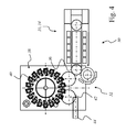
- the schematic representation of Fig. 4 shows a container forming apparatus 30 for stretch blow molding preforms to liquid containers.
- the container forming device 30 comprises a rotating preform inlet region 32, a heating section 34 with a controlled two-stage heating device 10 according to FIG Fig. 3 for the tempering of the preforms and a subsequent rotating first transfer star 36 for conveying the tempered preforms to a rotating stretch blower 38.
- This rotary stretch blower 38 has a plurality of blow molding stations 40, in which the preforms are formed into liquid containers before they by means of a second transfer star 42 are transferred to a linear conveying conveyor 44, with which the containers in particular to a filling station (not shown) are conveyed.
- the schematic representation of Fig. 5 shows a schematic representation of a heating section 34 according to Fig. 4 , the part of the heating device 10 according to Fig. 3 is.
- the first relatively cold preforms 46 which may have, for example, a temperature T1 of about 25 ° C, in the first heating stage 12 (see. Fig. 3 heated to a base heat T2 of about 55 ° C.
- this base heat T2 corresponds to the maximum thread temperature at which the preforms 46 can be exposed without the thread area being able to deform.
- the first heating stage 12 may optionally have a radiator region 48 with infrared radiators and / or additional heating rods 50, which can each dip into the rapid and precise heating of the preforms 46 in this. Both heaters 48 and 50 may optionally be combined, whereby the first Heating stage 12 acts as a booster 52, with which the preforms 46 can be brought quickly to exactly the desired basic temperature T2 (here: about 55 ° C).
- the adjoining second heating stage 14 also includes a radiator area 54 with infrared radiators, which are regulated differently, however, in order to produce the desired temperature profiling, so that on the one hand the necessary forming temperature T3 of about 100 ° C is achieved, but on the other hand the threaded area of the Preforms 46 remains at the temperature level of T2.
- FIG. 6 shows a schematic view of a preferred embodiment of the Be Strukturerumformungsvoriques according to Fig. 4 .
- the container-forming device 30 with the rotating inlet region 32 for the preforms, the heating section 34 with the controlled two-stage heater 10 according to Fig. 3 for tempering the preforms and the subsequent rotating first transfer star 36 for conveying the tempered preforms to the rotating stretch blower 38 illustrates.
- the preforms 46 are formed into liquid containers 56 by the blow molding stations 40 located at the outer circumference before being transferred by means of the second transfer star 42 to the conveyor 44, with which the containers 56 are conveyed to the filling station or other treatment station (not shown) become.
- the heating section 34 has just behind the inlet region 32, the booster 52 and the first heating stage 12 for basic temperature control of the preforms 46. Downstream of the booster 52, the radiator regions 54 of the second heating stage 14, indicated in the embodiment shown by a total of six consecutively arranged heating boxes.
- the rotating inlet area 32 with the inlet star is preceded by a linear feed area 58, with which the preforms 46 are fed to the container-forming device 30.
- This linear feed region 58 can be equipped with an additional preheating device 60 which, for example, can be fed by the waste heat of the heating device 10 or the like, so that in this way a considerable proportion of the heat energy otherwise dissipated unused for preheating the preforms and thus for Increasing the efficiency of the tempering process can be used.
- the remaining structure of the device 30 does not differ from the embodiment according to Fig. 6 ,
- the first temperature sensor 16 is located immediately after the first heating stage 12 or the booster 52.
- the second temperature sensor 20 is located behind the second heating stage 14, ie behind the last heating box with the radiator areas 54 arranged therein, as shown in FIGS FIGS. 6 and 7 each is clarified.
- a third temperature sensor 62 may be arranged in the linear feed region 58 and the preheating 60 or in front of these regions, as shown in FIG Fig. 7 is clarified.
- the output signal of this third temperature sensor 62 may preferably additionally in the control loop of the heating device 10 (see. Fig. 3 ).
- the detailed view of the Fig. 8 illustrates a variant of the first heating stage 12 and the booster 52.
- Fig. 5 be provided that to be heated to the base temperature T2 of about 55 ° C preform 46 by means of the fully immersed in this heating rod 50 and / or by means of the infrared radiator of the radiator region 48.
- the radiator of the radiator region 48 may preferably have a suitable cooling, which prevents overheating of the radiator in the heating furnace 10 by flowing cooling air.
Abstract
Description
Die vorliegende Erfindung betrifft ein Verfahren zur Temperatursteuerung und/oder -regelung einer Heizvorrichtung für Vorformlinge mit den Merkmalen des unabhängigen Verfahrensanspruchs 1. Die Erfindung betrifft weiterhin eine Heizvorrichtung zur Temperierung von Vorformlingen mit den Merkmalen des Anspruchs 7.The present invention relates to a method for temperature control and / or regulation of a heater for preforms with the features of the
Die Herstellung von Getränkebehältern aus thermoplastischem Kunststoff, insbesondere aus dem üblicherweise verwendeten PET, erfolgt üblicherweise mittels eines Streckblasverfahrens. Bei diesem meist zweistufigen Streckblasverfahren werden die Behälter üblicherweise aus spritzgegossenen, rotationssymmetrischen Vorformlingen (sog. Preforms) hergestellt. Diese Vorformlinge bestehen aus einem länglichen, zylindrischen Mantelabschnitt (sog. Body-Bereich) mit abgerundet geschlossenem Boden und einem Halsbereich mit oberer Öffnung, der auch als Mundstücksbereich bezeichnet werden kann. Nahe dieser Öffnung befindet sich normalerweise ein Gewindeabschnitt, der nach unten durch einen Kragen o. dgl. abgegrenzt sein kann. Der Gewindeabschnitt wird beim Spritzgießen des Vorformlings bereits auf das spätere Endmaß hergestellt. Er bleibt auch beim Streckblasvorgang in seiner ursprünglichen Form und bildet beim fertigen Getränkebehälter das Gewinde für den Verschlussdeckel. Der übrige Bereich des Vorformlings wird dagegen verformt und gedehnt. Bei der Verarbeitung werden diese Vorformlinge auf eine definierte Prozesstemperatur erwärmt, um den Umformvorgang beim Streckblasen in der gewünschten Weise zu ermöglichen. Die Erwärmung erfolgt meist mittels Infrarotstrahlung, da auf diese Weise eine definierte und gleichmäßige Temperierung der Vorformlinge ermöglicht ist.The production of beverage containers made of thermoplastic material, in particular from the commonly used PET, usually takes place by means of a stretch blow molding process. In this usually two-stage stretch blow molding process, the containers are usually produced from injection-molded, rotationally symmetrical preforms (so-called preforms). These preforms consist of an elongated, cylindrical shell section (so-called body region) with a rounded closed bottom and a neck region with an upper opening, which can also be referred to as the mouthpiece region. Close to this opening is usually a threaded portion which can be delimited by a collar o. The like. Down. The threaded portion is already produced during the injection molding of the preform to the later final dimension. He also remains in the stretch blow in its original form and forms the thread for the closure lid in the finished beverage container. The remaining area of the preform, however, is deformed and stretched. During processing, these preforms are heated to a defined process temperature in order to allow the stretch blow molding in the desired manner. The heating is usually carried out by means of infrared radiation, since in this way a defined and uniform temperature of the preforms is possible.
Das zu verarbeitende Kunststoffmaterial (i.d.R. PET) hat die Eigenschaft, dass es beim Verstrecken zu einer Selbstverfestigung (sog. "strain hardening") kommt. Dabei ist die Umformtemperatur von entscheidender Bedeutung. Der Effekt der Selbstverfestigung wird normalerweise bei der Produktion von PET-Behältern genutzt, um die Wanddickenverteilung der Behälter zu steuern und zu optimieren. Je nach Verarbeitungsverfahren können die Vorformlinge über die aufgebrachte Infrarotstrahlung mit einem Temperaturprofil beaufschlagt werden. Das Ziel hierbei ist es, die wärmeren Bereiche so lange vorrangig verformen zu lassen, bis der sich durch die Selbstverfestigung ergebende Verstreckungswiderstand größer wird als der Widerstand der benachbarten kälteren Bereiche. Üblicherweise ist das Temperaturprofil um den Umfang der Vorformlinge gleichmäßig verteilt und kann prozessabhängig in Längsrichtung der Vorformlinge variieren.The plastic material to be processed (usually PET) has the property that during stretching it comes to a self-hardening (so-called "strain hardening"). The forming temperature is of crucial importance here. The self-strengthening effect is normally used in the production of PET containers to control and optimize the wall thickness distribution of the containers. Depending on the processing method, the preforms can be applied via the applied infrared radiation be acted upon with a temperature profile. The aim here is to allow the warmer areas to deform as much as possible until the stretching resistance resulting from the self-consolidation becomes greater than the resistance of the adjacent colder areas. Usually, the temperature profile is evenly distributed around the circumference of the preforms and can vary depending on the process in the longitudinal direction of the preforms.
Um das gewünschte Temperaturprofil auf die Vorformlinge aufzutragen, können mehrere Zonen verwendet werden, bspw. bis zu neun Zonen oder mehr. Diese Mehrzahl von unterschiedlichen Zonen können individuell angesteuert werden, wobei die gewählte Einstellung über eine längere Betriebsdauer der Heizeinrichtung unverändert beibehalten wird. Um auf Veränderungen in den Umgebungsbedingungen reagieren zu können, kann eine Regelung verwendet werden, bei der die Temperatur der Vorformlinge an mindestens einer Messstelle erfasst wird. Über diese Regelung wird versucht, die Temperatur der Vorformlinge an der gewählten Messstelle konstant zu halten. Die Regelgröße bildet die Eingangsstellgröße für alle Heizeinrichtungen, so dass bei einer gemessenen Temperatur, die unterhalb einer eingestellten Solltemperatur liegt, alle Heizeinrichtungen mit einer erhöhten Stellgröße und dadurch mit einer höheren Heizleistung beaufschlagt werden.To apply the desired temperature profile to the preforms, multiple zones may be used, for example, up to nine zones or more. These plurality of different zones can be controlled individually, wherein the selected setting is maintained unchanged over a longer period of operation of the heater. In order to be able to react to changes in the ambient conditions, a regulation can be used in which the temperature of the preforms is detected at at least one measuring point. This regulation attempts to keep the preform temperature constant at the selected measuring point. The control variable forms the input control variable for all heaters, so that at a measured temperature which is below a set desired temperature, all heaters are subjected to an increased manipulated variable and thus with a higher heat output.
Diese Regelung ist i.d.R. unverzichtbar, da sich die Temperaturen der Vorformlinge im Laufe der Zeit verändern können, bspw. nach einiger Betriebdauer und sich allmählich erwärmender Heizeinrichtung. Auch kann sich die Produktionshalle bspw. während eines Betriebstages erwärmen, was ebenfalls Einfluss auf die Erwärmung der Heizeinrichtungen und der Vorformlinge haben kann. Wenn allerdings die Stellgröße zu stark verändert wird, können zwar die unterschiedlichen Heizzonen jeweils prozentual in gleichem Ausmaß beeinflusst und verändert werden, doch kann die Gesamterwärmung stärker als gewünscht abweichen, da sich das gesamte Heizprofil verändert. Durch zu starke Temperaturabweichungen von einer Solltemperatur kann die Behälterqualität negativ beeinflusst werden.This regulation is i.d.R. indispensable because the temperatures of the preforms may change over time, for example, after some operating time and gradually warming heater. Also, the production hall may, for example, heat up during a day of operation, which may also affect the heating of the heaters and the preforms. However, if the manipulated variable is changed too much, the different heating zones can each be influenced and changed to the same percentage, but the overall heating may deviate more than desired because the entire heating profile changes. Excessively high temperature deviations from a setpoint temperature can negatively affect container quality.
Um diese Probleme zu vermeiden, werden die unterschiedlichen Heizzonensteuerungen in der Praxis manuell angepasst. Zudem können verschiedene Programme für einen Sommerbetrieb und einen Winterbetrieb berücksichtigt werden.In order to avoid these problems, the different heating zone controls are manually adjusted in practice. In addition, various programs for a summer operation and a winter operation can be considered.
Ein vorrangiges Ziel der Erfindung besteht darin, ein verbessertes Verfahren zur Temperierung von Vorformlingen im Zusammenhang mit einem Streckblasverfahren zur Verfügung zu stellen, bei dem die Vorformlinge mit einer gewünschtenA primary object of the invention is to provide an improved process for the tempering of preforms in connection with a stretch blow molding method To provide, in which the preforms with a desired
Temperaturprofilierung beaufschlagt werden, die auch unter sich verändernden äußeren Bedingungen möglichst exakt den Sollwerten folgen kann. Ein weiteres Ziel der Erfindung besteht darin, eine verbesserte Heizvorrichtung für Vorformlinge zu schaffen, bei der die für die Vorformlinge wirksamen Temperaturen und Temperaturprofile möglichst exakt regelbar sind.Temperature profiling are applied, which can follow the setpoints as closely as possible even under changing external conditions. Another object of the invention is to provide an improved parison heater in which the temperatures and temperature profiles effective for the preforms are as accurately controlled as possible.
Diese Ziele der Erfindung werden mit den Gegenständen der unabhängigen Patentansprüche erreicht. Weitere vorteilhafte Ausgestaltungen werden durch die Unteransprüche beschrieben.These objects of the invention are achieved with the subject matters of the independent claims. Further advantageous embodiments are described by the subclaims.
Zur Erreichung des erstgenannten Ziels schlägt die Erfindung ein Verfahren zur Steuerung einer Heizvorrichtung für Vorformlinge aus thermoplastischem Kunststoff, insbesondere aus PET vor, mit dem die Heizvorrichtung in gewünschter Weise geregelt werden kann, um die Vorformlinge vor einem nachfolgenden Blas- bzw. Streckblasvorgang in optimaler Weise temperieren zu können. Der Temperierungsvorgang umfasst zwei getrennte, aufeinander folgende Heizstufen, die jeweils unterschiedliche Aufgaben erfüllen sollen. In der ersten Heizstufe soll eine annähernd gleichmäßige Grundtemperierung des gesamten Vorformlings erfolgen, die ungefähr einer maximalen Erwärmungstemperatur eines Gewindebereichs am oben offenen Halsabschnitt des Vorformlings für eine Aufrechterhaltung von dessen Formstabilität entspricht. In der zweiten Heizstufe soll eine entsprechend eines vorgebbaren Wärmeprofils, für den Blas- bzw. Streckblasvorgang erforderliche Temperaturprofilierung in Höhe der Umformtemperatur zumindest des unterhalb des Gewindebereichs und/oder eines darunter angeordneten Kragenbereichs des Vorformlings befindlichen Körperabschnittes erreicht werden. Mit der vorliegenden Erfindung wird ein verbessertes Konzept zur Temperaturschichtung für die Vorformlinge geschaffen. Die Erwärmung erfolgt zweistufig, um in den einzelnen Stufen eine direktere und besser angepasste Temperaturregelung zu ermöglichen.In order to achieve the first mentioned object, the invention proposes a method for controlling a heater for preforms made of thermoplastic material, in particular made of PET, with which the heater can be controlled in the desired manner to the preforms before a subsequent blowing or stretch blow molding in an optimal manner to be able to temper. The tempering process comprises two separate, successive heating stages, each intended to fulfill different tasks. In the first heating stage, an approximately uniform basic tempering of the entire preform is to take place, which corresponds approximately to a maximum heating temperature of a threaded region at the open-topped neck portion of the preform for maintaining its dimensional stability. In the second heating stage, a temperature profile corresponding to a predefinable heat profile, for the blown or stretch blow molding, is to be achieved at the level of the forming temperature of at least the body portion located below the thread region and / or a collar region of the preform arranged underneath. The present invention provides an improved concept for temperature stratification for the preforms. The heating is carried out in two stages to allow a more direct and better adapted temperature control in the individual stages.
Die Erwärmung erfolgt normalerweise in zwei aufeinander folgenden Abschnitten bzw. Heizstufen der Heizvorrichtung. Der erste Abschnitt liefert eine Grunderwärmung für die Vorformlinge, um diese möglichst gleichmäßig auf eine Grundtemperatur zu erwärmen, die unterhalb der Erweichungstemperatur für das Kunststoffmaterial liegt, um den Gewindebereich nach Möglichkeit nicht unzulässig zu erwärmen. In dieser Grunderwärmungsphase wird noch keine Temperaturschichtung aufgebracht, da eine gleichmäßige Temperaturverteilung über den ganzen Vorformlingkörper erreicht werden soll. Zu diesem Zweck kann ggf. über einen geeigneten Algorithmus eine Zonenschichtung in Abhängigkeit von der Geometrie des Vorformlings (Wanddicke, Entfernung zum Strahler, Länge) vorgegeben werden. Die beim erfindungsgemäßen Verfahren vorgesehene Regelung soll die Temperatur nach Möglichkeit immer auf eine definierte Grundtemperatur bringen, die zwischen mindestens 50°C und bis zu 90°C liegen kann. Auf diese Weise sollen die unterschiedlichen Eingangs- und Lagerbedingungen der Vorformlinge ausgeglichen werden. Da diese in unterschiedlichen Lagerorten bei unterschiedlichen Temperaturen gelagert und bevorratet werden können, bevor sie dem Streckblasvorgang zugeführt werden, ist es zur Erreichung möglichst guter Verformungsergebnisse notwendig, gleiche Eingangsbedingungen für die Vorformlinge zu schaffen. Demnach ist die erste Temperierungsstufe durch eine Grunderwärmungsphase und die zweite Temperierungsstufe durch eine nachfolgende Temperaturprofilierungsphase gebildet.The heating normally takes place in two successive sections or heating stages of the heating device. The first section provides a base heating for the preforms to heat them as evenly as possible to a base temperature that is below the softening temperature for the plastic material, so as not to unduly heat the threaded area as much as possible. In this Grunderwärmungsphase no temperature stratification is applied, as a uniform temperature distribution over the entire preform body is to be achieved. For this purpose, a zone stratification, depending on the geometry of the preform (wall thickness, distance to the radiator, length), may optionally be specified via a suitable algorithm. The regulation provided in the method according to the invention should always bring the temperature to a defined basic temperature whenever possible, which may be between at least 50.degree. C. and up to 90.degree. In this way, the different input and storage conditions of the preforms are to be compensated. Since these can be stored and stored in different storage locations at different temperatures before they are fed to the stretch blow, it is necessary to achieve the best possible deformation results to create equal input conditions for the preforms. Accordingly, the first tempering stage is formed by a basic heating phase and the second tempering stage by a subsequent temperature profiling phase.
In der den zweiten Abschnitt bildenden Temperaturprofilierungsphase werden die Vorformlinge mit in Längsrichtung unterschiedlich bzw. geschichteten Temperaturen beaufschlagt. Gemäß einer bevorzugten Variante des erfindungsgemäßen Verfahrens ist zumindest eine Temperaturmessung am Ausgang der ersten Heizstufe zur Erfassung der Temperatur der Vorformlinge nach ihrer Grundtemperierung und zur Anpassung der ersten Heizstufe vorgesehen. Wahlweise kann zumindest eine weitere Temperaturmessung nach der zweiten Heizstufe zur Erfassung der Endtemperatur der Vorformlinge nach der ersten Heizstufe bzw. der Temperaturprofilierungsphase und eine Berücksichtigung der gemessenen Temperaturen bei der Anpassung der ersten Heizstufe vorgesehen sein. Dabei wird zumindest die nach der ersten Heizstufe gemessene Temperatur zur Regelung der Heizleistung dieser ersten Heizstufe verarbeitet. Es kann auch vorgesehen sein, dass sowohl die nach der ersten Stufe bzw. der Grunderwärmungsphase gemessene Temperatur als auch die nach der zweiten Stufe bzw. der Temperaturprofilierungsphase gemessene Endtemperatur zur Regelung der Heizleistung der ersten Stufe verarbeitet wird. Es kann auch vorgesehen sein, dass sowohl die nach der ersten Stufe bzw. der Grunderwärmungsphase gemessene Temperatur als auch die nach der zweiten Stufe bzw. der Temperaturprofilierungsphase gemessene Endtemperatur zur Regelung der Heizleistung der ersten Stufe und/oder der zweiten Stufe verarbeitet wird.In the temperature profiling phase forming the second section, the preforms are subjected to different or layered temperatures in the longitudinal direction. According to a preferred variant of the method according to the invention, at least one temperature measurement is provided at the output of the first heating stage for detecting the temperature of the preforms after their basic temperature control and for adapting the first heating stage. Optionally, at least one further temperature measurement after the second heating stage for detecting the final temperature of the preforms after the first heating stage or the temperature profiling phase and a consideration of the measured temperatures during the adaptation of the first heating stage can be provided. In this case, at least the temperature measured after the first heating stage is processed to control the heating power of this first heating stage. It can also be provided that both the temperature measured after the first stage or the basic warming phase and the final temperature measured after the second stage or the temperature profiling phase are processed to control the heating power of the first stage. It can also be provided that both the temperature measured after the first stage or the basic warming phase and the final temperature measured after the second stage or the temperature profiling phase are processed to control the heating power of the first stage and / or the second stage.
In der Temperaturprofilierungsphase kann aufgrund der geregelten Temperatur in der Grunderwärmungsphase immer von Vorformlingen mit dem gleichen Ausgangszustand ausgegangen werden. Idealerweise würde sich die Temperaturschichtung danach nicht mehr verändern, so dass die Temperatur bzw. die Heizleistung der Heizstufen nicht mehr nachgeregelt werden müsste und somit auf einen Regelkreis verzichtet werden könnte. Um dennoch eine Kontrolle über die tatsächliche Temperatur der Vorformlinge zu erhalten und Nebeneffekte wie eine Alterung der Heizeinrichtungen wie Infrarotstrahler beim Einlauf in die Blasstation auszugleichen, sollte auch am Ofenausgang eine Temperaturmessung erfolgen. Der dabei gewonnene Messwert kann dazu verwendet werden, um den Stellwert der Ofenregelung für die Grunderwärmung anzupassen.In the temperature profiling phase, preforms with the same initial state can always be assumed due to the controlled temperature in the basic heating phase. Ideally, the temperature stratification would then no longer change, so that the temperature or the heat output of the heating stages would not have to be readjusted and thus could be dispensed with a control loop. Nevertheless, in order to obtain control over the actual temperature of the preforms and to compensate for side effects such as aging of the heaters such as infrared heaters when entering the blowing station, a temperature measurement should also be carried out at the furnace outlet. The measured value obtained can be used to adjust the control value of the basic heating control.
In einer alternativen Ausführungsform ist es auch möglich, den am Ofenausgang gemessenen Wert zur Regelung und Steuerung der zweiten Heizstufe zu verwenden, sofern dies auf Grund von Alterung der Heizeinrichtungen oder anderen Nebeneffekten notwendig ist. Bei der Regelung und Steuerung der zweiten Heizstufe wird vorzugsweise auch der Messwert, der nach der ersten Stufe ermittelt wurde, berücksichtigt.In an alternative embodiment, it is also possible to use the value measured at the furnace outlet to control and control the second heating stage, if this is necessary due to aging of the heaters or other side effects. In the regulation and control of the second heating stage, preferably also the measured value which was determined after the first stage is taken into account.
Von Vorteil ist es zudem, wenn die Vorformlinge im Bereich der ersten Heizstufe bzw. der Grunderwärmungsphase auf eine weitgehend gleichmäßige Grundtemperatur zwischen ca. 50°C und ca. 90°C temperiert werden. Diese Temperatur richtet sich in erster Linie nach der maximal zulässigen Temperatur für den Halsbereich der aus PET oder einem anderen geeigneten thermoplastischen Kunststoff bestehenden Vorformlinge, da dieser Bereich mit dem später verwendeten Gewinde während des Erwärmens und des nachfolgenden Streckblasens nicht verändert und verformt werden soll, sondern während der gesamten Verarbeitung maßhaltig und unverändert bleiben soll.It is also advantageous if the preforms in the region of the first heating stage or the basic warming phase to a substantially uniform base temperature between about 50 ° C and about 90 ° C are tempered. This temperature depends primarily on the maximum permissible temperature for the neck region of the preforms made of PET or another suitable thermoplastic, since this region is not to be changed and deformed with the thread used later during the heating and subsequent stretch blow molding, but instead should remain dimensionally stable and unchanged throughout the processing.
Eine vorteilhafte Variante des erfindungsgemäßen Verfahrens sieht vor, dass die Vorformlinge im Bereich der ersten Heizstufe mittels in die oben offenen Vorformlinge eintauchender Heizstäbe auf die Grundtemperatur erwärmt werden. Diese Heizstäbe wirken als sog. Booster, weil sie in der Lage sind, den jeweiligen Vorformling innerhalb einer sehr kurzen Zeit von der Lagertemperatur auf die gewünschte Grundtemperatur zu bringen, die in der nachfolgenden Heizstufe unter Aufprägung eines Temperaturprofils auf ein nochmals erhöhtes Temperaturniveau gebracht wird. Dieser Booster bzw. Heizstab kann eine typische Länge aufweisen, die einem einzelnen Heizstrahler entspricht, so dass damit eine weitgehend homogene Erwärmung der Vorformlinge ermöglicht ist. Darüber hinaus können jedoch auch weitere Strahler als Komponenten dieses Boosters fungieren, die für die gewünschte Grunderwärmung der Vorformlinge eine Wärmestrahlung von außen auf die Vorformlinge aufbringen. Darüber hinaus kann eine vorteilhafte Variante dadurch gebildet sein, dass für die Erzeugung der Grunderwärmung Teile einer Ofenabwärme genutzt werden, die ansonsten ungenutzt nach außen geleitet würde. Diese in vorteilhafter Weise zu nutzende Ofenabwärme kann bspw. durch Umlenkung warmer Abluft und/oder durch Leitung dieser Abluft durch geeignete Wärmetauscher genutzt und dadurch abgekühlt werden, so dass damit auch eine Energieeinsparung verbunden werden kann.An advantageous variant of the method according to the invention provides that the preforms in the region of the first heating stage are heated to the base temperature by means of heating rods immersed in the open-top preforms. These heating elements act as so-called booster because they are able to bring the respective preform within a very short time from the storage temperature to the desired basic temperature, which is brought in the subsequent heating stage under impressing a temperature profile to a further elevated temperature level. This booster or heating rod may have a typical length, which corresponds to a single radiant heater, so that thus a substantially homogeneous heating of the preforms is possible. About that In addition, however, other radiators can act as components of this booster, which apply a heat radiation from the outside to the preforms for the desired basic heating of the preforms. In addition, an advantageous variant can be formed in that parts of a furnace waste heat which would otherwise be passed on to the outside are used to generate the basic heating. This advantageously to be used furnace waste heat can be used, for example, by redirecting hot exhaust air and / or by conducting this exhaust air through suitable heat exchanger and thereby cooled, so that it can also be connected to energy conservation.
Wie bereits erwähnt, dient die zweite Heizstufe im Wesentlichen dazu, die Vorformlinge in dieser Temperaturprofilierungsphase mit einem über ihre Länge angepassten und/oder unterschiedlichen Temperaturprofil zu versehen. Hierbei ist darauf zu achten, den Gewindebereich beim Erwärmen des Halsabschnittes und des übrigen Vorformlings nicht zu stark zu erwärmen, damit er auch bei den nachfolgenden Verfahrensschritten seine Formstabilität beibehält. Da der Gewindebereich und der sog. Neckring für die Handhabung und den Transport benötigt werden, ist es wichtig, dass diese Bereiche des Vorformlings nicht modifiziert werden. Die Vorformlinge können im Bereich der zweiten Heizstufe insbesondere mittels Strahlungsheizeinrichtungen erwärmt werden. Diese können ggf. mit einer geregelten Oberflächenkühlung versehen sein, um Überhitzungen zu vermeiden.As already mentioned, the second heating stage essentially serves to provide the preforms in this temperature profiling phase with a temperature profile adapted and / or different over their length. Care should be taken not to overheat the threaded portion when heating the neck portion and the rest of the preform so that it retains its dimensional stability in the subsequent process steps. Since the threaded area and the so-called neck ring are required for handling and transportation, it is important that these areas of the preform are not modified. The preforms can be heated in the region of the second heating stage, in particular by means of radiant heaters. These may possibly be provided with a controlled surface cooling in order to avoid overheating.
Das entsprechend der erfindungsgemäßen Konfiguration geregelte Verfahren ermöglicht eine sehr schnelle Anpassung der Regelgrößen, d.h. der Heizleistung der ersten Heizstufe, da die für die Regelung zu berücksichtigende Eingangsgröße als gemessene Temperatur unmittelbar nach der ersten Heizstufe abgegriffen wird. Gegenüber bisher bekannten Messverfahren erfolgt dabei die Regelung bereits nach ca. der halben Heizstrecke, was ein zu starkes Abdriften der Regelgrößen verhindern kann. Da damit die Temperaturregelung exakter wird, kann auf effektive Weise die Verfahrensqualität erhöht und die Ausschussrate an fehlerhaft umgeformten Vorformlingen reduziert werden. In der zweiten Heizstufe wird die Temperaturschichtung vorzugsweise unter gleich bleibenden Bedingungen aufgebracht, wodurch ebenfalls das Abdriften der Prozessparameter verhindert und die gleich bleibende Qualität aufrechterhalten wird. Das beschriebene Heizsystem der Grunderwärmungsstufe mit den optional verwendbaren Boostern bzw. Heizstäben ist besonders energieeffizient zu betreiben, da auf diese Weise eine sehr schnelle Erwärmung der Vorformlinge auf die benötigte Prozesstemperatur erreicht werden kann.The method regulated in accordance with the configuration according to the invention allows a very rapid adaptation of the controlled variables, ie the heating power of the first heating stage, since the input variable to be taken into account as the measured temperature is tapped immediately after the first heating stage. Compared to previously known measuring method, the control already takes place after about half the heating distance, which can prevent excessive drifting of the controlled variables. As the temperature control becomes more accurate, the process quality can be effectively increased and the rejection rate of defective molded preforms can be reduced. In the second heating stage, the temperature stratification is preferably applied under constant conditions, which also prevents the drifting of the process parameters and the consistent quality is maintained. The described heating system of the basic heating stage with the optionally usable booster or heating rods is particularly energy efficient too operate, since in this way a very rapid heating of the preforms can be achieved to the required process temperature.
Ein weiterer Vorteil besteht darin, dass die Prozesse und Prozessparameter ohne Einschränkungen in den Maschinen implementiert werden können, wobei keinerlei Einschränkungen hinsichtlich der Übertragbarkeit auf gleichartige oder ähnliche Maschinen vorliegen, auch wenn diese jeweils abweichende Konfigurationen aufweisen sollten. Weiterhin werden alle denkbaren Einflüsse, die mit der Maschinenaufstellung und dem Standort zusammenhängen, weitgehend eliminiert, wodurch die Inbetriebnahme beschleunigt werden kann. Ein solcher Standortfaktor kann bspw. eine typische Hallentemperatur sein, die als Umgebungsparameter die Erwärmung der Vorformlinge spürbar beeinflussen könnte.A further advantage is that the processes and process parameters can be implemented without restrictions in the machines, with no restrictions on the transferability to similar or similar machines, even if they each have different configurations. Furthermore, all conceivable influences, which are connected with the machine installation and the location, are largely eliminated, whereby the commissioning can be accelerated. Such a location factor may be, for example, a typical hall temperature, which could appreciably affect the heating of the preforms as an environmental parameter.
Zur Erreichung des oben genannten Ziels der Erfindung ist zudem eine Heizvorrichtung zur Temperierung von Vorformlingen aus thermoplastischem Kunststoff für einen nachfolgenden Blas- bzw. Streckblasvorgang vorgesehen. Diese erfindungsgemäße Heizvorrichtung umfasst wenigstens zwei unterschiedliche bzw. aufeinander folgende Heizstufen, wobei zumindest die erste Heizstufe eine Heizvorrichtung zur weitgehend gleichmäßigen Grundtemperierung der Vorformlinge aufweist. Eine weitere Ausführungsvariante der erfindungsgemäßen Heizvorrichtung kann vorsehen, dass zumindest die erste Heizstufe durch wenigstens einen in die Vorformlinge eintauchenden Heizstab gebildet ist, der den Vorformling von innen erwärmt und auf die Grundtemperatur bringt.To achieve the above-mentioned aim of the invention, a heating device for tempering preforms made of thermoplastic material is also provided for a subsequent blown or stretch blow molding process. This heating device according to the invention comprises at least two different or successive heating stages, wherein at least the first heating stage has a heating device for largely uniform basic temperature control of the preforms. A further embodiment variant of the heating device according to the invention can provide that at least the first heating stage is formed by at least one heating rod immersed in the preforms, which heats the preform from the inside and brings it to the basic temperature.
Weiterhin kann vorgesehen sein, dass zumindest nach der ersten Heizstufe und vor der zweiten Heizstufe ein Temperatursensor angeordnet ist, der über eine Signalübertragung mit einer Regelungseinheit zur Regelung der Heizleistung der ersten Heizstufe gekoppelt ist, so dass die erste Heizstufe besonders schnell regelbar ist. Weiterhin kann am Ausgang der zweiten Heizstufe ein weiterer Temperatursensor angeordnet sein, der mit der Regelungseinheit gekoppelt ist. Damit kann die Regelungsgüte weiter verbessert werden. Weitere Aspekte, Ausführungsvarianten und Vorteile bei der Konfiguration und dem Betrieb der erfindungsgemäßen Heizvorrichtung sind im Zusammenhang mit den oben bereits genannten Verfahrensvarianten zu sehen, da diese Verfahrensvarianten allesamt als Optionen für einen Betrieb der Heizvorrichtung zu sehen sind.Furthermore, it can be provided that at least after the first heating stage and before the second heating stage, a temperature sensor is arranged, which is coupled via a signal transmission with a control unit for controlling the heating power of the first heating stage, so that the first heating stage is particularly fast regulated. Furthermore, at the output of the second heating stage, a further temperature sensor can be arranged, which is coupled to the control unit. Thus, the control quality can be further improved. Further aspects, design variants and advantages in the configuration and operation of the heating device according to the invention are to be seen in connection with the process variants already mentioned above, since these process variants are all to be regarded as options for operation of the heating device.
Weiterhin ist an dieser Stelle zu betonen, dass die vorliegende Erfindung grundsätzlich zur Anwendung in Mikrowellenöfen, Rundläuferöfen, Linearöfen, stationären Öfen etc. geeignet ist. Weiterhin ist die Verwendung von individuellen Heiztaschen denkbar, wobei jeder Vorformling in einer separaten Heiztasche selektiv temperiert wird. Ergänzend sei darauf hingewiesen, dass neben den erwähnten zwei getrennten Heizstufen ggf. weitere Heizstufen vorgesehen sein können, ohne dass dies an dieser Stelle im Detail erläutert ist.Furthermore, it should be emphasized at this point that the present invention is basically suitable for use in microwave ovens, rotary ovens, linear ovens, stationary ovens, etc. Furthermore, the use of individual heating bags is conceivable, each preform is selectively tempered in a separate heating bag. In addition, it should be noted that in addition to the aforementioned two separate heat levels, if necessary, further heating stages can be provided, without this being explained in detail at this point.
Im Folgenden sollen Ausführungsbeispiele die Erfindung und ihre Vorteile anhand der beigefügten Figuren näher erläutern. Die Größenverhältnisse der einzelnen Elemente zueinander in den Figuren entsprechend nicht immer den realen Größenverhältnissen, da einige Formen vereinfacht und andere Formen zur besseren Veranschaulichung vergrößert im Verhältnis zu anderen Elementen dargestellt sind.
-
Fig. 1 zeigt anhand eines Diagramms die Zusammenhänge von Dehnung und daraus resultierender Materialspannung bei der Verformung von PET-Material. -
Fig. 2 zeigt anhand eines weiteren Diagramms ein Temperaturprofil, mit dem ein Vorformling an unterschiedlichen Abschnitten jeweils einer unterschiedlichen Erwärmung unterzogen wird. -
Fig. 3 zeigt ein schematisches Blockschaltbild einer in einem Regelkreis verknüpften zweistufigen Heizvorrichtung. -
Fig. 4 zeigt eine schematische Darstellung einer Behälterformungsvorrichtung zur Streckblasumformung von Vorformlingen zu Flüssigkeitsbehältern. -
Fig. 5 zeigt in einer schematischen Darstellung eine Heizstrecke gemäßFig. 4 . -
Fig. 6 zeigt eine schematische Ansicht einer bevorzugten Ausführungsvariante der Behälterumformungsvorrichtung gemäßFig. 4 . -
Fig. 7 zeigt eine weitere Variante einer Behälterumformungsvorrichtung mit einer zusätzlichen Vorwärmung. -
Fig. 8 zeigt eine Detailansicht des Boosters bzw. der ersten Heizstufe.
-
Fig. 1 shows a diagram of the relationships between strain and resulting material stress in the deformation of PET material. -
Fig. 2 shows on the basis of another diagram, a temperature profile with which a preform is subjected at different sections each of a different heating. -
Fig. 3 shows a schematic block diagram of a connected in a control loop two-stage heater. -
Fig. 4 shows a schematic representation of a container forming apparatus for stretch blow molding of preforms to liquid containers. -
Fig. 5 shows a schematic representation of a heating section according toFig. 4 , -
Fig. 6 shows a schematic view of a preferred embodiment of the Behälterumformungsvorrichtung according toFig. 4 , -
Fig. 7 shows a further variant of a container-forming device with an additional preheating. -
Fig. 8 shows a detailed view of the booster or the first heating stage.
Für gleiche oder gleich wirkende Elemente der Erfindung werden identische Bezugszeichen verwendet. Ferner werden der Übersicht halber nur Bezugszeichen in den einzelnen Figuren dargestellt, die für die Beschreibung der jeweiligen Figur erforderlich sind. Die dargestellten Ausführungsformen stellen lediglich Beispiele dar, wie die erfindungsgemäße Vorrichtung oder das erfindungsgemäße Verfahren ausgestaltet sein können und stellen keine abschließende Begrenzung dar.For identical or equivalent elements of the invention, identical reference numerals are used. Furthermore, for the sake of clarity only reference numerals in the individual figures that are required for the description of the respective figure. The illustrated embodiments are merely examples of how the device or method of the invention may be configured and are not an exhaustive limitation.
Die Darstellung der
Die Darstellung der
Die
Um die gewünschte Regelung der Heizvorrichtung 10 zu ermöglichen, ist ein erster Temperatursensor 16 zur Erfassung einer Ist-Temperatur 18 am Ausgang der ersten Heizstufe 12 zur möglichst exakten Erfassung der Temperatur der Vorformlinge nach ihrer Grundtemperierung und zur Anpassung der ersten Heizstufe 12 vorgesehen. Das Ausgangssignal des ersten Temperatursensors 16 liefert einen Wert für die Ist-Temperatur 18. Weiterhin kann eine weitere Temperaturmessung nach der zweiten Heizstufe 14 mittels eines zweiten Temperatursensors 20 vorgesehen sein, die zur Erfassung der Endtemperatur der Vorformlinge nach der Temperaturprofilierungsphase in der zweiten Heizstufe 14 dient. Der mit dem zweiten Temperatursensor 20 gemessene Wert für eine Soll-Temperatur 22 wird zusammen mit der vom ersten Temperatursensor 16 gelieferten Ist-Temperatur 18 in einer Summierschaltung 24 und einer nachgeordneten Verstärkerstufe 26 zur Ansteuerung der ersten Heizstufe 12, der Grunderwärmungsstufe, verarbeitet. Auf die beschriebene Weise kann ein sehr schnell reagierendes Regelsystem zur Ofenregelung realisiert werden, bei dem aufgrund der günstigen Platzierung der beiden Temperatursensoren 16 und 20 ein starkes Abweichen der Heiztemperaturen der beiden Heizstufen 12 und 14 zuverlässig verhindert werden kann.In order to enable the desired control of the
Die Vorformlinge können im Bereich der ersten Heizstufe 12 bzw. der Grunderwärmungsphase auf eine weitgehend gleichmäßige Grundtemperatur zwischen ca. 50°C und ca. 90°C temperiert werden. Diese Temperatur muss zumindest unterhalb der Fließ- bzw. Erweichungstemperatur des für die Vorformlinge verwendeten thermoplastischen Kunststoffs liegen, da insbesondere der Gewindebereich bei der in der ersten Heizstufe 12 erfolgenden Temperierung formstabil bleiben muss, da dort keine Abschirmung bzw. Kühlung des Hals- und Gewindebereichs erfolgt, wie dies in der zweiten Heizstufe 14 normalerweise der Fall ist. Die Vorformlinge können im Bereich der ersten Heizstufe 12 bspw. mittels in die oben offenen Vorformlinge eintauchender Heizstäbe auf die Grundtemperatur erwärmt werden. Anschließend werden die Vorformlinge im Bereich der zweiten Heizstufe 14 bzw. der Temperaturprofilierungsphase mit einem über ihre Länge angepassten und/oder unterschiedlichen Temperaturprofil beaufschlagt, was bspw. mit in unterschiedlichen Höhen unterschiedlich stark abstrahlenden Strahlerleisten zur Erzeugung einer angepassten Infrarotstrahlung erfolgen kann.The preforms can be tempered in the region of the
Die schematische Darstellung der
Die schematische Darstellung der
Die sich daran anschließende zweite Heizstufe 14 umfasst ebenfalls einen Strahlerbereich 54 mit Infrarotstrahlern, die jedoch unterschiedlich geregelt sind, um die gewünschte Temperaturprofilierung zu erzeugen, so dass einerseits die notwendige Umformtemperatur T3 von ca. 100°C erreicht wird, dass aber andererseits der Gewindebereich der Vorformlinge 46 auf dem Temperaturniveau von T2 bleibt.The adjoining
Die Darstellung der
Die Heizstrecke 34 weist knapp hinter dem Einlaufbereich 32 den Booster 52 bzw. die erste Heizstufe 12 zur Grundtemperierung der Vorformlinge 46 auf. Dem Booster 52 nachgeordnet sind die Strahlerbereiche 54 der zweiten Heizstufe 14, im gezeigten Ausführungsbeispiel durch insgesamt sechs hintereinander angeordnete Heizkästen angedeutet. Dem rotierenden Einlaufbereich 32 mit dem Einlaufstern ist ein linearer Zuführbereich 58 vorgeordnet, mit dem die Vorformlinge 46 der Behälterumformungsvorrichtung 30 zugeführt werden.The
Entsprechend
Beiden Varianten gemäß
Die Detailansicht der
Die Erfindung wurde unter Bezugnahme auf eine bevorzugte Ausführungsform beschrieben. Es ist jedoch für einen Fachmann vorstellbar, dass Abwandlungen oder Änderungen der Erfindung gemacht werden können, ohne dabei den Schutzbereich der nachstehenden Ansprüche zu verlassen.The invention has been described with reference to a preferred embodiment. However, it will be apparent to those skilled in the art that modifications or changes may be made to the invention without departing from the scope of the following claims.
- 1010
- Heizvorrichtungheater
- 1212
- Erste HeizstufeFirst heating stage
- 1414
- Zweite HeizstufeSecond heating stage
- 1616
- Erster TemperatursensorFirst temperature sensor
- 1818
- Ist-TemperaturActual temperature
- 2020
- Zweiter TemperatursensorSecond temperature sensor
- 2222
- Soll-TemperaturTarget temperature
- 2424
- Summierschaltungsumming
- 2626
- Verstärkerstufeamplifier stage
- 3030
- BehälterumformungsvorrichtungContainer forming device
- 3232
- Einlaufbereichintake area
- 3434
- Heizstreckeheating section
- 3636
- Erster ÜbergabesternFirst handover star
- 3838
- Streckblasvorrichtungstretch blow
- 4040
- Blasformstationblow molding
- 4242
- Zweiter ÜbergabesternSecond transfer star
- 4444
- Fördervorrichtungconveyor
- 4646
- Vorformlingpreform
- 4848
- Strahlerbereichemitter area
- 5050
- Heizstabheater
- 5252
- Boosterbooster
- 5454
- Strahlerbereichemitter area
- 5656
- Flüssigkeitsbehälterliquid container
- 5858
- Linearer ZuführbereichLinear feed area
- 6060
- Vorwärmvorrichtungpreheating
- 6262
- Dritter TemperatursensorThird temperature sensor
Claims (10)
Applications Claiming Priority (1)
| Application Number | Priority Date | Filing Date | Title |
|---|---|---|---|
| DE102010021445A DE102010021445A1 (en) | 2010-05-25 | 2010-05-25 | Method and device for temperature control and / or regulation of a preform heater |
Publications (2)
| Publication Number | Publication Date |
|---|---|
| EP2390082A1 true EP2390082A1 (en) | 2011-11-30 |
| EP2390082B1 EP2390082B1 (en) | 2014-03-05 |
Family
ID=44562696
Family Applications (2)
| Application Number | Title | Priority Date | Filing Date |
|---|---|---|---|
| EP11165220.2A Active EP2390082B1 (en) | 2010-05-25 | 2011-05-09 | Apparatus and method for controlling and/or regulating temperature of a heating device for preforms |
| EP11167225.9A Active EP2390083B1 (en) | 2010-05-25 | 2011-05-24 | Apparatus and method for controlling and/or regulating temperature of a heating device for preforms |
Family Applications After (1)
| Application Number | Title | Priority Date | Filing Date |
|---|---|---|---|
| EP11167225.9A Active EP2390083B1 (en) | 2010-05-25 | 2011-05-24 | Apparatus and method for controlling and/or regulating temperature of a heating device for preforms |
Country Status (4)
| Country | Link |
|---|---|
| US (2) | US20110294085A1 (en) |
| EP (2) | EP2390082B1 (en) |
| CN (2) | CN102310555B (en) |
| DE (1) | DE102010021445A1 (en) |
Cited By (1)
| Publication number | Priority date | Publication date | Assignee | Title |
|---|---|---|---|---|
| WO2019048628A1 (en) * | 2017-09-07 | 2019-03-14 | Krones Ag | Device and method for heating plastic preforms with a controllable heating power |
Families Citing this family (15)
| Publication number | Priority date | Publication date | Assignee | Title |
|---|---|---|---|---|
| GB0804266D0 (en) * | 2008-03-07 | 2008-04-16 | Univ Belfast | Thermoplastic preform method and apparatus |
| DE102010021445A1 (en) * | 2010-05-25 | 2011-12-01 | Krones Ag | Method and device for temperature control and / or regulation of a preform heater |
| DE102015101769A1 (en) | 2015-02-06 | 2016-08-11 | Krones Ag | Method for calibrating at least one treatment element |
| JP6523035B2 (en) * | 2015-04-30 | 2019-05-29 | 株式会社吉野工業所 | Liquid blow molding apparatus and liquid blow molding method |
| DE102016103117A1 (en) | 2016-02-23 | 2017-08-24 | Krones Ag | Method for operating a treatment plant for treating containers with recipe creation for the controller |
| FR3053908B1 (en) * | 2016-12-23 | 2018-08-17 | Sidel Participations | METHOD FOR PARAMETERSING A HEATING STATION OF A CONTAINER PRODUCTION PLANT |
| DE102017119492A1 (en) | 2017-08-25 | 2019-02-28 | Krones Ag | Method and apparatus for heating plastic preforms |
| DE102017120862A1 (en) * | 2017-09-10 | 2019-03-14 | Khs Corpoplast Gmbh | Heating device for the temperature conditioning of preforms and method for operating such a heating device |
| CN108664445B (en) * | 2018-04-16 | 2022-11-25 | 深圳和而泰小家电智能科技有限公司 | Temperature calculation method and electronic equipment |
| CN110351918A (en) * | 2018-12-17 | 2019-10-18 | 四川大学 | A kind of method and apparatus of the realization microwave heating curve based on temperature feedback and phased array |
| DE102020123166A1 (en) | 2020-09-04 | 2022-03-10 | Krones Aktiengesellschaft | Device and method for heating plastic preforms with spatially resolved temperature detection |
| CN112223725B (en) * | 2020-09-23 | 2022-06-28 | 四川科伦药业股份有限公司 | Injection-blowing integrated manufacturing method for plastic infusion container |
| CN115494889B (en) * | 2021-10-15 | 2023-11-17 | 义乌市绘海科技有限公司 | Extrusion temperature control system and method for corrugated pipe extruder |
| CN114878200B (en) * | 2022-07-08 | 2022-09-30 | 中国飞机强度研究所 | Aerospace plane component strength test heating system and method |
| WO2024047604A1 (en) * | 2022-09-02 | 2024-03-07 | S.I.P.A. Societa' Industrializzazione Progettazione E Automazione S.P.A. | Heating system for heating plastic material preforms |
Citations (4)
| Publication number | Priority date | Publication date | Assignee | Title |
|---|---|---|---|---|
| US4117050A (en) * | 1975-10-08 | 1978-09-26 | Gildemeister Corpoplast Gmbh | Method for heating and blow molding plaster parisons |
| DE102007022386A1 (en) * | 2006-05-11 | 2007-11-15 | Krones Ag | Heating plastic preforms used in e.g. bottle manufacture, employs annular microwave resonator around region to be heated |
| EP1974891A1 (en) * | 2006-01-20 | 2008-10-01 | Toyo Seikan Kaisya, Ltd. | Process for producing bottle of biaxially oriented polyester |
| DE102007016028A1 (en) * | 2007-03-30 | 2008-10-16 | Sig Technology Ag | Method for blow molding of containers, involves forming preform made of thermal condensing material in container after thermal condensation along transport path in area of heating section within blow mold by blowing pressure effect |
Family Cites Families (18)
| Publication number | Priority date | Publication date | Assignee | Title |
|---|---|---|---|---|
| JPS6045045B2 (en) * | 1977-12-27 | 1985-10-07 | 株式会社吉野工業所 | Stretch blow molding equipment |
| US5032700A (en) * | 1987-06-09 | 1991-07-16 | Toyo Seikan Kaisha, Ltd. | Method of heating thermoplastic bottle of preform and method of controlling temperature of heating member utilized by the heating method |
| JP3262393B2 (en) * | 1992-12-29 | 2002-03-04 | 日精エー・エス・ビー機械株式会社 | Heat control method of intermediate molded product for blow molding |
| AT521U1 (en) * | 1994-11-08 | 1995-12-27 | Kosme Etikettiertechnik Ges M | METHOD FOR SETTING PROCESS PARAMETERS IN THE PRODUCTION OF HOLLOW BODIES FROM THERMOPLASTIC PREFORMS, AND DEVICE FOR IMPLEMENTING THE METHOD |
| US5607706A (en) * | 1995-04-05 | 1997-03-04 | Husky Injection Molding Systems Ltd. | Preconditioning preforms on a reheat blow molding system |
| IT1294138B1 (en) * | 1997-07-03 | 1999-03-22 | Sipa Spa | HIGH PRODUCTIVITY SINGLE-STAGE PROCESS AND APPARATUS FOR THE PRODUCTION OF THERMOPLASTIC RESIN CONTAINERS |
| DE19757818A1 (en) * | 1997-12-24 | 1999-07-01 | Krupp Corpoplast Masch | Process for tempering preforms and device for tempering |
| US6258313B1 (en) * | 1999-05-04 | 2001-07-10 | Container Corporation International Inc. | Stretch blow molding process and apparatus for the manufacturing of plastic containers |
| DE10259589B3 (en) * | 2002-12-19 | 2004-04-01 | Krones Ag | Heating inspected preforms for stretch blow molding of e.g. plastic drinks bottles, heats at least some preforms known to be defective, before elimination |
| JP4356066B2 (en) * | 2003-10-17 | 2009-11-04 | 東洋製罐株式会社 | Manufacturing method and manufacturing apparatus for container comprising compression molding and stretch blow molding |
| US7220378B2 (en) * | 2004-01-07 | 2007-05-22 | Pressco Technology Inc. | Method and apparatus for the measurement and control of both the inside and outside surface temperature of thermoplastic preforms during stretch blow molding operations |
| US7425296B2 (en) * | 2004-12-03 | 2008-09-16 | Pressco Technology Inc. | Method and system for wavelength specific thermal irradiation and treatment |
| EP2021161B1 (en) * | 2006-05-11 | 2016-04-27 | Krones Aktiengesellschaft | Method for heating plastic preforms by means of microwaves |
| DE102006049163A1 (en) * | 2006-10-18 | 2008-05-08 | Sig Technology Ag | Method and apparatus for blow molding containers |
| FR2907684B1 (en) * | 2006-10-26 | 2009-12-04 | Sidel Participations | METHOD OF STERILIZING A PREFORM, INSTALLATION AND OVEN FOR MANUFACTURING STERILE CONTAINERS ACCORDING TO THIS PROCESS |
| DE102008013419A1 (en) * | 2008-03-06 | 2009-09-10 | Khs Corpoplast Gmbh & Co. Kg | Method and apparatus for blow molding containers |
| DE102010021445A1 (en) * | 2010-05-25 | 2011-12-01 | Krones Ag | Method and device for temperature control and / or regulation of a preform heater |
| DE102010021446A1 (en) * | 2010-05-25 | 2011-12-01 | Krones Ag | Method and device for tempering preforms |
-
2010
- 2010-05-25 DE DE102010021445A patent/DE102010021445A1/en not_active Withdrawn
-
2011
- 2011-05-09 EP EP11165220.2A patent/EP2390082B1/en active Active
- 2011-05-24 US US13/068,918 patent/US20110294085A1/en not_active Abandoned
- 2011-05-24 US US13/068,921 patent/US20110294086A1/en not_active Abandoned
- 2011-05-24 EP EP11167225.9A patent/EP2390083B1/en active Active
- 2011-05-25 CN CN201110137342.4A patent/CN102310555B/en active Active
- 2011-05-25 CN CN201110137430.4A patent/CN102259424B/en active Active
Patent Citations (4)
| Publication number | Priority date | Publication date | Assignee | Title |
|---|---|---|---|---|
| US4117050A (en) * | 1975-10-08 | 1978-09-26 | Gildemeister Corpoplast Gmbh | Method for heating and blow molding plaster parisons |
| EP1974891A1 (en) * | 2006-01-20 | 2008-10-01 | Toyo Seikan Kaisya, Ltd. | Process for producing bottle of biaxially oriented polyester |
| DE102007022386A1 (en) * | 2006-05-11 | 2007-11-15 | Krones Ag | Heating plastic preforms used in e.g. bottle manufacture, employs annular microwave resonator around region to be heated |
| DE102007016028A1 (en) * | 2007-03-30 | 2008-10-16 | Sig Technology Ag | Method for blow molding of containers, involves forming preform made of thermal condensing material in container after thermal condensation along transport path in area of heating section within blow mold by blowing pressure effect |
Cited By (2)
| Publication number | Priority date | Publication date | Assignee | Title |
|---|---|---|---|---|
| WO2019048628A1 (en) * | 2017-09-07 | 2019-03-14 | Krones Ag | Device and method for heating plastic preforms with a controllable heating power |
| US11260571B2 (en) | 2017-09-07 | 2022-03-01 | Krones Ag | Apparatus and method for heating plastic preforms with controllable heating power |
Also Published As
| Publication number | Publication date |
|---|---|
| CN102259424A (en) | 2011-11-30 |
| EP2390083B1 (en) | 2014-04-30 |
| EP2390083A1 (en) | 2011-11-30 |
| CN102310555B (en) | 2014-12-03 |
| EP2390082B1 (en) | 2014-03-05 |
| DE102010021445A1 (en) | 2011-12-01 |
| CN102310555A (en) | 2012-01-11 |
| CN102259424B (en) | 2014-08-27 |
| US20110294085A1 (en) | 2011-12-01 |
| US20110294086A1 (en) | 2011-12-01 |
Similar Documents
| Publication | Publication Date | Title |
|---|---|---|
| EP2390082B1 (en) | Apparatus and method for controlling and/or regulating temperature of a heating device for preforms | |
| EP2390081A2 (en) | Method and device for tempering preforms | |
| EP1998950B1 (en) | Process and apparatus for the blow moulding of containers using wall-thickness measurement on the moulded article | |
| EP2100712B1 (en) | Device and method for heating preforms | |
| EP3672779A1 (en) | Method and device for heating plastic preforms | |
| DE10121160A1 (en) | Method and device for tempering preforms | |
| EP2687447B1 (en) | Shrinking device with optimised energy management | |
| EP3717200B1 (en) | Temperature control device for the thermal conditioning of preforms and method for operating such a temperature control device | |
| EP2081752B1 (en) | Method and device for blow moulding containers | |
| EP2307185A1 (en) | Method and apparatus for blow molding receptacles | |
| DE102016119703A1 (en) | Method and device for producing molded parts with a semi-finished product | |
| EP3681691B1 (en) | Heating device for the temperature conditioning of preforms, and method for operating a heating device of this kind | |
| EP3102384B1 (en) | Method and device for tempering preforms | |
| DE102017120634A1 (en) | Apparatus and method for heating plastic preforms with controllable heating power | |
| EP3964349B1 (en) | Method and device for heating plastic pre-forms with spatially resolved temperature detection | |
| DE102014108048A1 (en) | Apparatus and method for heating plastic preforms with adjustable surface cooling | |
| EP4241960A1 (en) | Operating method for a heating device for the temperature conditioning of preforms in a start-up phase, heating device and machine | |
| EP3964348B1 (en) | Method and device for heating plastic pre-forms with spatially resolved temperature detection | |
| EP4197740A1 (en) | Device and method for heating plastic pre-forms with adjustment of the heating power | |
| DE102022109966A1 (en) | Heating method and heating device for the thermal conditioning of preforms, and container manufacturing machine for the forming of preforms with a heating device |
Legal Events
| Date | Code | Title | Description |
|---|---|---|---|
| AK | Designated contracting states |
Kind code of ref document: A1 Designated state(s): AL AT BE BG CH CY CZ DE DK EE ES FI FR GB GR HR HU IE IS IT LI LT LU LV MC MK MT NL NO PL PT RO RS SE SI SK SM TR |
|
| AX | Request for extension of the european patent |
Extension state: BA ME |
|
| PUAI | Public reference made under article 153(3) epc to a published international application that has entered the european phase |
Free format text: ORIGINAL CODE: 0009012 |
|
| 17P | Request for examination filed |
Effective date: 20120503 |
|
| 17Q | First examination report despatched |
Effective date: 20130220 |
|
| GRAP | Despatch of communication of intention to grant a patent |
Free format text: ORIGINAL CODE: EPIDOSNIGR1 |
|
| INTG | Intention to grant announced |
Effective date: 20130814 |
|
| RIN1 | Information on inventor provided before grant (corrected) |
Inventor name: SENN, KONRAD Inventor name: HIRDINA, JOCHEN Inventor name: VOTH, KLAUS |
|
| GRAP | Despatch of communication of intention to grant a patent |
Free format text: ORIGINAL CODE: EPIDOSNIGR1 |
|
| INTG | Intention to grant announced |
Effective date: 20140108 |
|
| GRAS | Grant fee paid |
Free format text: ORIGINAL CODE: EPIDOSNIGR3 |
|
| GRAA | (expected) grant |
Free format text: ORIGINAL CODE: 0009210 |
|
| AK | Designated contracting states |
Kind code of ref document: B1 Designated state(s): AL AT BE BG CH CY CZ DE DK EE ES FI FR GB GR HR HU IE IS IT LI LT LU LV MC MK MT NL NO PL PT RO RS SE SI SK SM TR |
|
| REG | Reference to a national code |
Ref country code: GB Ref legal event code: FG4D Free format text: NOT ENGLISH |
|
| REG | Reference to a national code |
Ref country code: CH Ref legal event code: EP |
|
| REG | Reference to a national code |
Ref country code: AT Ref legal event code: REF Ref document number: 654526 Country of ref document: AT Kind code of ref document: T Effective date: 20140315 |
|
| REG | Reference to a national code |
Ref country code: IE Ref legal event code: FG4D Free format text: LANGUAGE OF EP DOCUMENT: GERMAN |
|
| REG | Reference to a national code |
Ref country code: DE Ref legal event code: R096 Ref document number: 502011002270 Country of ref document: DE Effective date: 20140417 |
|
| REG | Reference to a national code |
Ref country code: NL Ref legal event code: VDEP Effective date: 20140305 |
|
| PG25 | Lapsed in a contracting state [announced via postgrant information from national office to epo] |
Ref country code: NO Free format text: LAPSE BECAUSE OF FAILURE TO SUBMIT A TRANSLATION OF THE DESCRIPTION OR TO PAY THE FEE WITHIN THE PRESCRIBED TIME-LIMIT Effective date: 20140605 Ref country code: LT Free format text: LAPSE BECAUSE OF FAILURE TO SUBMIT A TRANSLATION OF THE DESCRIPTION OR TO PAY THE FEE WITHIN THE PRESCRIBED TIME-LIMIT Effective date: 20140305 |
|
| REG | Reference to a national code |
Ref country code: LT Ref legal event code: MG4D |
|
| PG25 | Lapsed in a contracting state [announced via postgrant information from national office to epo] |
Ref country code: SE Free format text: LAPSE BECAUSE OF FAILURE TO SUBMIT A TRANSLATION OF THE DESCRIPTION OR TO PAY THE FEE WITHIN THE PRESCRIBED TIME-LIMIT Effective date: 20140305 Ref country code: FI Free format text: LAPSE BECAUSE OF FAILURE TO SUBMIT A TRANSLATION OF THE DESCRIPTION OR TO PAY THE FEE WITHIN THE PRESCRIBED TIME-LIMIT Effective date: 20140305 Ref country code: CY Free format text: LAPSE BECAUSE OF FAILURE TO SUBMIT A TRANSLATION OF THE DESCRIPTION OR TO PAY THE FEE WITHIN THE PRESCRIBED TIME-LIMIT Effective date: 20140305 |
|
| PG25 | Lapsed in a contracting state [announced via postgrant information from national office to epo] |
Ref country code: LV Free format text: LAPSE BECAUSE OF FAILURE TO SUBMIT A TRANSLATION OF THE DESCRIPTION OR TO PAY THE FEE WITHIN THE PRESCRIBED TIME-LIMIT Effective date: 20140305 Ref country code: RS Free format text: LAPSE BECAUSE OF FAILURE TO SUBMIT A TRANSLATION OF THE DESCRIPTION OR TO PAY THE FEE WITHIN THE PRESCRIBED TIME-LIMIT Effective date: 20140305 Ref country code: HR Free format text: LAPSE BECAUSE OF FAILURE TO SUBMIT A TRANSLATION OF THE DESCRIPTION OR TO PAY THE FEE WITHIN THE PRESCRIBED TIME-LIMIT Effective date: 20140305 |
|
| PG25 | Lapsed in a contracting state [announced via postgrant information from national office to epo] |
Ref country code: EE Free format text: LAPSE BECAUSE OF FAILURE TO SUBMIT A TRANSLATION OF THE DESCRIPTION OR TO PAY THE FEE WITHIN THE PRESCRIBED TIME-LIMIT Effective date: 20140305 Ref country code: RO Free format text: LAPSE BECAUSE OF FAILURE TO SUBMIT A TRANSLATION OF THE DESCRIPTION OR TO PAY THE FEE WITHIN THE PRESCRIBED TIME-LIMIT Effective date: 20140305 Ref country code: CZ Free format text: LAPSE BECAUSE OF FAILURE TO SUBMIT A TRANSLATION OF THE DESCRIPTION OR TO PAY THE FEE WITHIN THE PRESCRIBED TIME-LIMIT Effective date: 20140305 Ref country code: NL Free format text: LAPSE BECAUSE OF FAILURE TO SUBMIT A TRANSLATION OF THE DESCRIPTION OR TO PAY THE FEE WITHIN THE PRESCRIBED TIME-LIMIT Effective date: 20140305 Ref country code: IS Free format text: LAPSE BECAUSE OF FAILURE TO SUBMIT A TRANSLATION OF THE DESCRIPTION OR TO PAY THE FEE WITHIN THE PRESCRIBED TIME-LIMIT Effective date: 20140705 Ref country code: BG Free format text: LAPSE BECAUSE OF FAILURE TO SUBMIT A TRANSLATION OF THE DESCRIPTION OR TO PAY THE FEE WITHIN THE PRESCRIBED TIME-LIMIT Effective date: 20140605 |
|
| PG25 | Lapsed in a contracting state [announced via postgrant information from national office to epo] |
Ref country code: ES Free format text: LAPSE BECAUSE OF FAILURE TO SUBMIT A TRANSLATION OF THE DESCRIPTION OR TO PAY THE FEE WITHIN THE PRESCRIBED TIME-LIMIT Effective date: 20140305 Ref country code: PL Free format text: LAPSE BECAUSE OF FAILURE TO SUBMIT A TRANSLATION OF THE DESCRIPTION OR TO PAY THE FEE WITHIN THE PRESCRIBED TIME-LIMIT Effective date: 20140305 Ref country code: SK Free format text: LAPSE BECAUSE OF FAILURE TO SUBMIT A TRANSLATION OF THE DESCRIPTION OR TO PAY THE FEE WITHIN THE PRESCRIBED TIME-LIMIT Effective date: 20140305 |
|
| REG | Reference to a national code |
Ref country code: DE Ref legal event code: R097 Ref document number: 502011002270 Country of ref document: DE |
|
| PG25 | Lapsed in a contracting state [announced via postgrant information from national office to epo] |
Ref country code: PT Free format text: LAPSE BECAUSE OF FAILURE TO SUBMIT A TRANSLATION OF THE DESCRIPTION OR TO PAY THE FEE WITHIN THE PRESCRIBED TIME-LIMIT Effective date: 20140707 Ref country code: LU Free format text: LAPSE BECAUSE OF FAILURE TO SUBMIT A TRANSLATION OF THE DESCRIPTION OR TO PAY THE FEE WITHIN THE PRESCRIBED TIME-LIMIT Effective date: 20140509 |
|
| REG | Reference to a national code |
Ref country code: CH Ref legal event code: PL |
|
| PLBE | No opposition filed within time limit |
Free format text: ORIGINAL CODE: 0009261 |
|
| STAA | Information on the status of an ep patent application or granted ep patent |
Free format text: STATUS: NO OPPOSITION FILED WITHIN TIME LIMIT |
|
| PG25 | Lapsed in a contracting state [announced via postgrant information from national office to epo] |
Ref country code: LI Free format text: LAPSE BECAUSE OF NON-PAYMENT OF DUE FEES Effective date: 20140531 Ref country code: MC Free format text: LAPSE BECAUSE OF FAILURE TO SUBMIT A TRANSLATION OF THE DESCRIPTION OR TO PAY THE FEE WITHIN THE PRESCRIBED TIME-LIMIT Effective date: 20140305 Ref country code: CH Free format text: LAPSE BECAUSE OF NON-PAYMENT OF DUE FEES Effective date: 20140531 Ref country code: DK Free format text: LAPSE BECAUSE OF FAILURE TO SUBMIT A TRANSLATION OF THE DESCRIPTION OR TO PAY THE FEE WITHIN THE PRESCRIBED TIME-LIMIT Effective date: 20140305 |
|
| 26N | No opposition filed |
Effective date: 20141208 |
|
| REG | Reference to a national code |
Ref country code: IE Ref legal event code: MM4A |
|
| REG | Reference to a national code |
Ref country code: DE Ref legal event code: R097 Ref document number: 502011002270 Country of ref document: DE Effective date: 20141208 |
|
| PG25 | Lapsed in a contracting state [announced via postgrant information from national office to epo] |
Ref country code: IE Free format text: LAPSE BECAUSE OF NON-PAYMENT OF DUE FEES Effective date: 20140509 |
|
| PG25 | Lapsed in a contracting state [announced via postgrant information from national office to epo] |
Ref country code: SI Free format text: LAPSE BECAUSE OF FAILURE TO SUBMIT A TRANSLATION OF THE DESCRIPTION OR TO PAY THE FEE WITHIN THE PRESCRIBED TIME-LIMIT Effective date: 20140305 |
|
| GBPC | Gb: european patent ceased through non-payment of renewal fee |
Effective date: 20150509 |
|
| PG25 | Lapsed in a contracting state [announced via postgrant information from national office to epo] |
Ref country code: MT Free format text: LAPSE BECAUSE OF FAILURE TO SUBMIT A TRANSLATION OF THE DESCRIPTION OR TO PAY THE FEE WITHIN THE PRESCRIBED TIME-LIMIT Effective date: 20140305 |
|
| REG | Reference to a national code |
Ref country code: FR Ref legal event code: PLFP Year of fee payment: 6 |
|
| PG25 | Lapsed in a contracting state [announced via postgrant information from national office to epo] |
Ref country code: SM Free format text: LAPSE BECAUSE OF FAILURE TO SUBMIT A TRANSLATION OF THE DESCRIPTION OR TO PAY THE FEE WITHIN THE PRESCRIBED TIME-LIMIT Effective date: 20140305 Ref country code: GB Free format text: LAPSE BECAUSE OF NON-PAYMENT OF DUE FEES Effective date: 20150509 |
|
| PG25 | Lapsed in a contracting state [announced via postgrant information from national office to epo] |
Ref country code: GR Free format text: LAPSE BECAUSE OF FAILURE TO SUBMIT A TRANSLATION OF THE DESCRIPTION OR TO PAY THE FEE WITHIN THE PRESCRIBED TIME-LIMIT Effective date: 20140606 |
|
| PG25 | Lapsed in a contracting state [announced via postgrant information from national office to epo] |
Ref country code: BE Free format text: LAPSE BECAUSE OF FAILURE TO SUBMIT A TRANSLATION OF THE DESCRIPTION OR TO PAY THE FEE WITHIN THE PRESCRIBED TIME-LIMIT Effective date: 20140531 Ref country code: TR Free format text: LAPSE BECAUSE OF FAILURE TO SUBMIT A TRANSLATION OF THE DESCRIPTION OR TO PAY THE FEE WITHIN THE PRESCRIBED TIME-LIMIT Effective date: 20140305 Ref country code: HU Free format text: LAPSE BECAUSE OF FAILURE TO SUBMIT A TRANSLATION OF THE DESCRIPTION OR TO PAY THE FEE WITHIN THE PRESCRIBED TIME-LIMIT; INVALID AB INITIO Effective date: 20110509 |
|
| REG | Reference to a national code |
Ref country code: FR Ref legal event code: PLFP Year of fee payment: 7 |
|
| REG | Reference to a national code |
Ref country code: AT Ref legal event code: MM01 Ref document number: 654526 Country of ref document: AT Kind code of ref document: T Effective date: 20160509 |
|
| PG25 | Lapsed in a contracting state [announced via postgrant information from national office to epo] |
Ref country code: AT Free format text: LAPSE BECAUSE OF NON-PAYMENT OF DUE FEES Effective date: 20160509 |
|
| REG | Reference to a national code |
Ref country code: FR Ref legal event code: PLFP Year of fee payment: 8 |
|
| PG25 | Lapsed in a contracting state [announced via postgrant information from national office to epo] |
Ref country code: MK Free format text: LAPSE BECAUSE OF FAILURE TO SUBMIT A TRANSLATION OF THE DESCRIPTION OR TO PAY THE FEE WITHIN THE PRESCRIBED TIME-LIMIT Effective date: 20140305 |
|
| PG25 | Lapsed in a contracting state [announced via postgrant information from national office to epo] |
Ref country code: AL Free format text: LAPSE BECAUSE OF FAILURE TO SUBMIT A TRANSLATION OF THE DESCRIPTION OR TO PAY THE FEE WITHIN THE PRESCRIBED TIME-LIMIT Effective date: 20140305 |
|
| REG | Reference to a national code |
Ref country code: FR Ref legal event code: PLFP Year of fee payment: 13 |
|
| P01 | Opt-out of the competence of the unified patent court (upc) registered |
Effective date: 20230523 |
|
| PGFP | Annual fee paid to national office [announced via postgrant information from national office to epo] |
Ref country code: IT Payment date: 20230412 Year of fee payment: 13 Ref country code: FR Payment date: 20230411 Year of fee payment: 13 Ref country code: DE Payment date: 20230331 Year of fee payment: 13 |