EP2386806A1 - Monitoring faults in the heating circuit of an appliance - Google Patents
Monitoring faults in the heating circuit of an appliance Download PDFInfo
- Publication number
- EP2386806A1 EP2386806A1 EP11158006A EP11158006A EP2386806A1 EP 2386806 A1 EP2386806 A1 EP 2386806A1 EP 11158006 A EP11158006 A EP 11158006A EP 11158006 A EP11158006 A EP 11158006A EP 2386806 A1 EP2386806 A1 EP 2386806A1
- Authority
- EP
- European Patent Office
- Prior art keywords
- heating circuit
- heating
- electric potential
- detected
- voltage
- Prior art date
- Legal status (The legal status is an assumption and is not a legal conclusion. Google has not performed a legal analysis and makes no representation as to the accuracy of the status listed.)
- Granted
Links
- 238000010438 heat treatment Methods 0.000 title claims abstract description 123
- 238000012544 monitoring process Methods 0.000 title claims abstract description 31
- 230000005611 electricity Effects 0.000 claims abstract description 25
- 239000012530 fluid Substances 0.000 claims abstract description 14
- 230000007257 malfunction Effects 0.000 claims abstract description 12
- 238000000034 method Methods 0.000 claims description 6
- 238000005406 washing Methods 0.000 description 10
- 239000007788 liquid Substances 0.000 description 6
- 238000001035 drying Methods 0.000 description 4
- 230000007935 neutral effect Effects 0.000 description 2
- 238000013021 overheating Methods 0.000 description 2
- 238000011144 upstream manufacturing Methods 0.000 description 2
- 230000000694 effects Effects 0.000 description 1
- 238000010412 laundry washing Methods 0.000 description 1
- 239000008237 rinsing water Substances 0.000 description 1
Images
Classifications
-
- F—MECHANICAL ENGINEERING; LIGHTING; HEATING; WEAPONS; BLASTING
- F24—HEATING; RANGES; VENTILATING
- F24H—FLUID HEATERS, e.g. WATER OR AIR HEATERS, HAVING HEAT-GENERATING MEANS, e.g. HEAT PUMPS, IN GENERAL
- F24H9/00—Details
- F24H9/20—Arrangement or mounting of control or safety devices
- F24H9/2007—Arrangement or mounting of control or safety devices for water heaters
- F24H9/2014—Arrangement or mounting of control or safety devices for water heaters using electrical energy supply
-
- A—HUMAN NECESSITIES
- A47—FURNITURE; DOMESTIC ARTICLES OR APPLIANCES; COFFEE MILLS; SPICE MILLS; SUCTION CLEANERS IN GENERAL
- A47L—DOMESTIC WASHING OR CLEANING; SUCTION CLEANERS IN GENERAL
- A47L15/00—Washing or rinsing machines for crockery or tableware
- A47L15/0018—Controlling processes, i.e. processes to control the operation of the machine characterised by the purpose or target of the control
- A47L15/0049—Detection or prevention of malfunction, including accident prevention
-
- D—TEXTILES; PAPER
- D06—TREATMENT OF TEXTILES OR THE LIKE; LAUNDERING; FLEXIBLE MATERIALS NOT OTHERWISE PROVIDED FOR
- D06F—LAUNDERING, DRYING, IRONING, PRESSING OR FOLDING TEXTILE ARTICLES
- D06F33/00—Control of operations performed in washing machines or washer-dryers
- D06F33/30—Control of washing machines characterised by the purpose or target of the control
- D06F33/47—Responding to irregular working conditions, e.g. malfunctioning of pumps
-
- A—HUMAN NECESSITIES
- A47—FURNITURE; DOMESTIC ARTICLES OR APPLIANCES; COFFEE MILLS; SPICE MILLS; SUCTION CLEANERS IN GENERAL
- A47L—DOMESTIC WASHING OR CLEANING; SUCTION CLEANERS IN GENERAL
- A47L15/00—Washing or rinsing machines for crockery or tableware
- A47L15/42—Details
- A47L15/4285—Water-heater arrangements
-
- A—HUMAN NECESSITIES
- A47—FURNITURE; DOMESTIC ARTICLES OR APPLIANCES; COFFEE MILLS; SPICE MILLS; SUCTION CLEANERS IN GENERAL
- A47L—DOMESTIC WASHING OR CLEANING; SUCTION CLEANERS IN GENERAL
- A47L15/00—Washing or rinsing machines for crockery or tableware
- A47L15/42—Details
- A47L15/46—Devices for the automatic control of the different phases of cleaning ; Controlling devices
-
- A—HUMAN NECESSITIES
- A47—FURNITURE; DOMESTIC ARTICLES OR APPLIANCES; COFFEE MILLS; SPICE MILLS; SUCTION CLEANERS IN GENERAL
- A47L—DOMESTIC WASHING OR CLEANING; SUCTION CLEANERS IN GENERAL
- A47L2401/00—Automatic detection in controlling methods of washing or rinsing machines for crockery or tableware, e.g. information provided by sensors entered into controlling devices
- A47L2401/26—Loading door status, e.g. door latch opened or closed state
-
- A—HUMAN NECESSITIES
- A47—FURNITURE; DOMESTIC ARTICLES OR APPLIANCES; COFFEE MILLS; SPICE MILLS; SUCTION CLEANERS IN GENERAL
- A47L—DOMESTIC WASHING OR CLEANING; SUCTION CLEANERS IN GENERAL
- A47L2401/00—Automatic detection in controlling methods of washing or rinsing machines for crockery or tableware, e.g. information provided by sensors entered into controlling devices
- A47L2401/30—Variation of electrical, magnetical or optical quantities
-
- A—HUMAN NECESSITIES
- A47—FURNITURE; DOMESTIC ARTICLES OR APPLIANCES; COFFEE MILLS; SPICE MILLS; SUCTION CLEANERS IN GENERAL
- A47L—DOMESTIC WASHING OR CLEANING; SUCTION CLEANERS IN GENERAL
- A47L2501/00—Output in controlling method of washing or rinsing machines for crockery or tableware, i.e. quantities or components controlled, or actions performed by the controlling device executing the controlling method
- A47L2501/06—Water heaters
-
- A—HUMAN NECESSITIES
- A47—FURNITURE; DOMESTIC ARTICLES OR APPLIANCES; COFFEE MILLS; SPICE MILLS; SUCTION CLEANERS IN GENERAL
- A47L—DOMESTIC WASHING OR CLEANING; SUCTION CLEANERS IN GENERAL
- A47L2501/00—Output in controlling method of washing or rinsing machines for crockery or tableware, i.e. quantities or components controlled, or actions performed by the controlling device executing the controlling method
- A47L2501/11—Air heaters
-
- A—HUMAN NECESSITIES
- A47—FURNITURE; DOMESTIC ARTICLES OR APPLIANCES; COFFEE MILLS; SPICE MILLS; SUCTION CLEANERS IN GENERAL
- A47L—DOMESTIC WASHING OR CLEANING; SUCTION CLEANERS IN GENERAL
- A47L2501/00—Output in controlling method of washing or rinsing machines for crockery or tableware, i.e. quantities or components controlled, or actions performed by the controlling device executing the controlling method
- A47L2501/26—Indication or alarm to the controlling device or to the user
-
- A—HUMAN NECESSITIES
- A47—FURNITURE; DOMESTIC ARTICLES OR APPLIANCES; COFFEE MILLS; SPICE MILLS; SUCTION CLEANERS IN GENERAL
- A47L—DOMESTIC WASHING OR CLEANING; SUCTION CLEANERS IN GENERAL
- A47L2501/00—Output in controlling method of washing or rinsing machines for crockery or tableware, i.e. quantities or components controlled, or actions performed by the controlling device executing the controlling method
- A47L2501/28—Machine starting, e.g. normal start, restart after electricity cut-off or start scheduling
-
- A—HUMAN NECESSITIES
- A47—FURNITURE; DOMESTIC ARTICLES OR APPLIANCES; COFFEE MILLS; SPICE MILLS; SUCTION CLEANERS IN GENERAL
- A47L—DOMESTIC WASHING OR CLEANING; SUCTION CLEANERS IN GENERAL
- A47L2501/00—Output in controlling method of washing or rinsing machines for crockery or tableware, i.e. quantities or components controlled, or actions performed by the controlling device executing the controlling method
- A47L2501/32—Stopping or disabling machine operation, including disconnecting the machine from a network, e.g. from an electrical power supply
-
- D—TEXTILES; PAPER
- D06—TREATMENT OF TEXTILES OR THE LIKE; LAUNDERING; FLEXIBLE MATERIALS NOT OTHERWISE PROVIDED FOR
- D06F—LAUNDERING, DRYING, IRONING, PRESSING OR FOLDING TEXTILE ARTICLES
- D06F2103/00—Parameters monitored or detected for the control of domestic laundry washing machines, washer-dryers or laundry dryers
- D06F2103/52—Parameters monitored or detected for the control of domestic laundry washing machines, washer-dryers or laundry dryers related to electric heating means, e.g. temperature or voltage
-
- D—TEXTILES; PAPER
- D06—TREATMENT OF TEXTILES OR THE LIKE; LAUNDERING; FLEXIBLE MATERIALS NOT OTHERWISE PROVIDED FOR
- D06F—LAUNDERING, DRYING, IRONING, PRESSING OR FOLDING TEXTILE ARTICLES
- D06F2105/00—Systems or parameters controlled or affected by the control systems of washing machines, washer-dryers or laundry dryers
- D06F2105/28—Electric heating
-
- D—TEXTILES; PAPER
- D06—TREATMENT OF TEXTILES OR THE LIKE; LAUNDERING; FLEXIBLE MATERIALS NOT OTHERWISE PROVIDED FOR
- D06F—LAUNDERING, DRYING, IRONING, PRESSING OR FOLDING TEXTILE ARTICLES
- D06F39/00—Details of washing machines not specific to a single type of machines covered by groups D06F9/00 - D06F27/00
- D06F39/04—Heating arrangements
Definitions
- the present invention generally relates to the field of household appliances, and particularly to household appliances such as washing machines, laundry washer/dryers, laundry dryers, dishwashers, and in general to all those appliances that include a heating circuit for heating a fluid (laundry or dishes washing liquid, or air for drying the laundry).
- a heating circuit for heating a fluid laundry or dishes washing liquid, or air for drying the laundry.
- the heating circuits provided in the above-mentioned appliances usually include a heating element consisting of a resistor, and a switch (e.g. a relay controlled by a control unit of the appliance) to selectively provide energy to the resistor when required, e.g. for heating the laundry or dishes washing liquid, or for heating the flow of laundry drying air.
- a switch e.g. a relay controlled by a control unit of the appliance
- the heating circuit is monitored to assess its proper operation or to detect possible faults thereof. Faults can occur in particular in the heating resistor or in the switch that supplies it.
- the monitoring of the heating circuit serves to assess if the heating resistor is energized or not, or if it is shorted to ground. Some faults can be harmful to the appliance or even extremely dangerous for the safety of the users. For example, it is necessary to prevent the heating resistor from overheating, to avoid damage to components of the appliance or fire; a short circuit to ground of the heating resistor is also potentially risky, because the leakage currents can reach the outer casing of the appliance and cause an electric shock to the unaware user. If any such fault is detected, the operation of the appliance should be stopped.
- Solutions are known for monitoring the heating circuit that call for detecting one or more electrical potential in certain circuit nodes of the heating circuit, and comparing the measured electrical potential with predetermined values stored in the control unit of the appliance.
- the Applicant has tackled the problem of devising a solution to monitor the heating circuit of an appliance that would overcome the above problems and ensure greater reliability.
- an appliance comprising a heating circuit for heating a fluid, said fluid heating circuit comprising a heating element selectively energizable to determine the heating of the fluid, and a monitoring unit for monitoring the operation of the heating circuit, said monitoring unit being configured for:
- the monitoring unit can be configured to recognize the state of proper functioning or malfunctioning of the heating circuit based on a comparison of the at least one measured electrical potential internal to the heating circuit and at least one reference electrical potential, derived by the monitoring unit in a dynamic way, for example, periodically, during the operation of the appliance, starting from the detected value of the voltage of the electricity distribution network.
- the monitoring unit can be configured to calculate, from the detected value of the voltage of the electricity distribution network, a first and a second reference electrical potentials, to be used for the comparison with the at least one measured internal electrical potential, and to recognize the state of proper functioning or malfunctioning of the heating circuit when the at least one measured internal electrical potential does not fall within a range of values between the first and second electrical potentials.
- the monitoring unit can be configured for:
- Said at least one electrical potential internal to the heating circuit may in particular be at least one of:
- a method is provided of monitoring a heating circuit of an appliance, said heating circuit being provided for heating a fluid and comprising a heating element that can be selectively energized to determine the heating of the fluid, the method comprising:
- the state of proper functioning or malfunctioning of the heating circuit can for instance be assessed based on a comparison of the at least one measured electrical potential internal to the heating circuit and at least one reference electrical potential, derived in a dynamic way, for example periodically, during the operation of the appliance starting from the detected value of the voltage of the electricity distribution network.
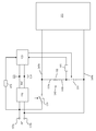
- references 105a and 105b in the figure denote electrical terminals of the appliance (for example, a laundry washing machine, a laundry washer/dryer, a laundry dryer, a dishwasher, and more generally, an appliance that includes a heating circuit for heating a fluid) which, in use, are inserted into a socket of an electrical system of a house, to receive the alternate current (AC), for example, the terminal 105a is connected to the terminal of a plug that can be inserted into the socket port connected to the phase voltage, and the terminal 105b is connected to the plug terminal that can be inserted into the socket port connected to the neutral.
- AC voltage the value of the AC voltage depends on the standard adopted in the generic country; common standards are 220 V @ 50 Hz nominal (as in the case of the standard adopted in Europe) and 110 V @ 60 Hz nominal (as in the U.S. standard).
- the AC voltage of the electricity distribution network is supplied to a voltage transformer and rectifier assembly 110, to generate one or more direct current (DC) voltage values 115 (referred to a reference voltage or ground 120), for example a voltage of 5 V to supply a logic control unit 125 that includes for example a microprocessor or microcontroller programmed to control the appliance operation.
- DC direct current
- Block 130 is intended to represent all the components of the appliance which, for their operation, are powered by the alternating voltage of the electricity distribution network, distributed through the appliance by distribution lines 145a and 145b; such components include, for example, in the case of a washing machine, the electric motor for rotating the drum, the pump for draining the washing/rinsing liquid, the solenoid valve(s) for loading the washing/rinsing water.
- a main switch 135, controlled by the control unit 125, allows selectively supplying all the electrical parts of the appliance; the control unit 125 can, for safety reasons, give the consent to the closure of the switch 135 only if the proper closing of a door or porthole of the appliance is detected, thus preventing the appliance from being started if the door is not closed, and switching the appliance off should the door be opened during operation.
- Reference 140 identifies a heating circuit, for example, in the case of a washing machine, for heating the washing liquid.
- the heating circuit 140 in the illustrative embodiment described herein, is connected to the distribution lines 145a and 145b of the AC network voltage downstream of the main switch 135, however, in alternative embodiments, it may be connected upstream of the switch 135.
- the heating circuit 140 comprises at least one heating resistor 150, which is connected in series to at least one switch 155, controlled by the control unit 125.
- the heating resistor 150 is the component which, when supplied, heats up by Joule effect and determines the heating of the laundry or dishes washing liquid or of the flow of air for drying the laundry.
- the switch 155 can, for example, be a monostable or bistable relay.
- the control unit 125 controls the closing of the switch 155 when, during an operating cycle of the appliance, the washing liquid, or the flow of laundry drying air, has to be heated.
- the heating resistor 150 has a terminal 160a connected to the phase distribution line 145a and a terminal 160b connected to a first terminal of the switch 155, and the latter has a second terminal connected to the neutral distribution line 145b, but there is nothing that prevents from reversing the positions of the heating resistor 150 and switch 155.
- thermo-fuses can be provided, for protection against overheating and burning of the resistor 150.
- the control unit 125 monitors the proper functioning of the heating circuit 140. To this end, in one embodiment of the present invention, the control unit 125 monitors at least one electrical potential internal to the heating circuit 140, said internal electrical potential being detected at at least one node of the heating circuit. In particular, in the exemplary embodiment here considered, the control unit 125 detects (via a voltage divider 165, such as a resistive voltage divider) the electrical potential at the terminal 160b of the heating resistor 150. In alternative embodiments, the at least one internal electrical potential detected by the control unit 125 could be detected at the terminal 160a of the heating resistor 150.
- control unit 125 monitors the voltage of the electricity distribution network.
- control unit 125 detects (via a voltage divider 170, such as a resistive voltage divider) the electrical potential of the phase (terminal 105a).
- the assessment of the proper functioning of the heating circuit 140 or a malfunction or failure thereof is based on a comparison, made by the control unit 125, between the detected voltage of the electricity distribution network and the at least one measured electrical potential internal to the heating circuit.
- control unit 125 dynamically calculates one or more comparison voltages, which are used to make a comparison with the electric potential measured in the heating circuit 140. These comparison voltage values are calculated repeatedly over time, e.g. at regular intervals, e.g. every 20 - 80 ms.
- control unit 125 calculates two reference voltage values, from which, through a mathematical calculation, two respective dimensionless reference numerical values X1 and X2 are derived.
- control unit 125 calculates a dimensionless numerical value X.
- the dimensionless numerical value X is compared by the control unit 125 to the two dimensionless reference numerical values X1 and X2 (with X1 ⁇ X2).
- the controller 125 declares a state of malfunction or failure of the heating circuit.
- the control unit 125 can for example choose to deactivate the heating circuit 140, by opening the switch 155, and/or to halt the appliance by opening the main switch 135.
- the control unit 125 in addition to monitoring the proper operation of the heating circuit 140 while it is activated, can monitor the operation thereof even when it is turned off (switch 155 open).
- the control unit 125 determines a malfunction of the heating circuit 140, which may consist in the fact that the switch 155 is stuck closed, or that the heating resistor 150 is shorted to ground; if instead the command given by the control unit 125 to the switch 155 corresponds to the closure thereof, but the electric potential observed at the terminal 160b of the heating resistor 150 is relatively high (and in particular the value X is greater than the reference value X2), the control unit 125 is able to determine a malfunction of the heating circuit 140, which consists in that the heating resistor 150 is shorted to the phase voltage.
- the monitoring of the proper functioning of the heating circuit is reliable even if the value of the alternating voltage of the electricity distribution network varies, taking into account the fact that the standard values of the network alternating voltage vary in general from country to country, and the fact that the network alternating voltage normally fluctuates over time around the nominal value.
- the heating circuit may include a safety switch (this could be particularly useful if the heating system is connected upstream of the main switch, so as to be able to deactivate the heating circuit in case of failure of the switch 155 without necessarily having to power down the whole appliance); the safety switch may be connected between the phase distribution line and the terminal 160a of the heating resistor 150, and the at least one electrical potential internal to the heating circuit detected by the control unit 125 may then be the potential at the terminal 160a of the heating resistor, connected to the safety switch.
- a safety switch this could be particularly useful if the heating system is connected upstream of the main switch, so as to be able to deactivate the heating circuit in case of failure of the switch 155 without necessarily having to power down the whole appliance
- the safety switch may be connected between the phase distribution line and the terminal 160a of the heating resistor 150, and the at least one electrical potential internal to the heating circuit detected by the control unit 125 may then be the potential at the terminal 160a of the heating resistor, connected to the safety switch.
Abstract
- an internal electric potential detected at a first terminal (160b) of the heating element (150) connected to an on/off switch (155) of the heating circuit (140);
- an internal electric potential detected at a second terminal (160a) of the heating element (150) connected to a main switch (135) of the appliance or to a safety switch provided for switching the heating circuit off in case of malfunction of the on/off switch (155)
wherein the monitoring unit (125) is further configured for:
- detecting a value of the voltage of the electricity distribution network; and
- calculating, starting from the detected value of the voltage of the electricity distribution network, a first and a second reference electric potentials,
- comparing said at least one detected internal electric potential with the first and second reference electric potentials;
- recognizing a state of good operation or malfunction of the heating circuit (140) in case said at least one detected internal electric potential does not fall within a range of values comprised between the first and second reference electric potentials.
Description
- The present invention generally relates to the field of household appliances, and particularly to household appliances such as washing machines, laundry washer/dryers, laundry dryers, dishwashers, and in general to all those appliances that include a heating circuit for heating a fluid (laundry or dishes washing liquid, or air for drying the laundry).
- The heating circuits provided in the above-mentioned appliances usually include a heating element consisting of a resistor, and a switch (e.g. a relay controlled by a control unit of the appliance) to selectively provide energy to the resistor when required, e.g. for heating the laundry or dishes washing liquid, or for heating the flow of laundry drying air.
- The heating circuit is monitored to assess its proper operation or to detect possible faults thereof. Faults can occur in particular in the heating resistor or in the switch that supplies it. The monitoring of the heating circuit serves to assess if the heating resistor is energized or not, or if it is shorted to ground. Some faults can be harmful to the appliance or even extremely dangerous for the safety of the users. For example, it is necessary to prevent the heating resistor from overheating, to avoid damage to components of the appliance or fire; a short circuit to ground of the heating resistor is also potentially risky, because the leakage currents can reach the outer casing of the appliance and cause an electric shock to the unaware user. If any such fault is detected, the operation of the appliance should be stopped.
- Solutions are known for monitoring the heating circuit that call for detecting one or more electrical potential in certain circuit nodes of the heating circuit, and comparing the measured electrical potential with predetermined values stored in the control unit of the appliance.
- The Applicant has observed that this solution exhibits drawbacks, since the different values taken by the nominal AC voltage in different countries, and also the fluctuations in time of the nominal AC voltage value in the same country, make the monitoring impractical and unreliable. For example, in order to take into account the different standards adopted in different countries, it would be necessary to produce differentiated appliances for different markets with different prestored electric potential values.
- The Applicant has tackled the problem of devising a solution to monitor the heating circuit of an appliance that would overcome the above problems and ensure greater reliability.
- According to an aspect of the present invention, an appliance is provided comprising a heating circuit for heating a fluid, said fluid heating circuit comprising a heating element selectively energizable to determine the heating of the fluid, and a monitoring unit for monitoring the operation of the heating circuit, said monitoring unit being configured for:
- monitoring at least one electrical potential internal to the heating circuit,
- detecting a value of the voltage of the electricity distribution network, and
- recognize a state of proper functioning or malfunctioning of the heating circuit on the basis of a comparison between the at least one measured electrical potential internal to the heating circuit and the detected value of the voltage of the electricity distribution network.
- In particular, the monitoring unit can be configured to recognize the state of proper functioning or malfunctioning of the heating circuit based on a comparison of the at least one measured electrical potential internal to the heating circuit and at least one reference electrical potential, derived by the monitoring unit in a dynamic way, for example, periodically, during the operation of the appliance, starting from the detected value of the voltage of the electricity distribution network.
- The monitoring unit can be configured to calculate, from the detected value of the voltage of the electricity distribution network, a first and a second reference electrical potentials, to be used for the comparison with the at least one measured internal electrical potential, and to recognize the state of proper functioning or malfunctioning of the heating circuit when the at least one measured internal electrical potential does not fall within a range of values between the first and second electrical potentials.
- In one embodiment of the present invention, the monitoring unit can be configured for:
- calculating, starting from the detected value of electricity distribution network voltage, a first and a second dimensionless numeric values;
- calculating, starting from the at least one measured internal electrical potential, a third dimensionless numeric value;
- comparing the third dimensionless numeric value with the first and second dimensionless numeric values, and
- recognizing the state of proper functioning or malfunctioning of the heating circuit if the third dimensionless numeric value does not fall within a range of values between the first and second dimensionless numeric values.
- These first and second dimensionless numeric values can be calculated periodically.
- Said at least one electrical potential internal to the heating circuit may in particular be at least one of:
- an internal electric potential measured at a first terminal of the heating element connected to a heating circuit on/off switch;
- an internal electric potential measured at a second terminal of the heating element connected to a main switch of the appliance or to a safety switch provided to turn the heating circuit off in case of malfunctioning of the on/off switch.
- According to another aspect of the present invention, a method is provided of monitoring a heating circuit of an appliance, said heating circuit being provided for heating a fluid and comprising a heating element that can be selectively energized to determine the heating of the fluid, the method comprising:
- monitoring at least one electrical potential internal to the heating circuit,
- detecting a value of a voltage of the electricity distribution network, and
- recognizing a state of proper functioning or malfunctioning of the heating circuit on the basis of a comparison between the at least one measured electrical potential internal to the heating circuit and the detected value of the voltage of the electricity distribution network.
- The state of proper functioning or malfunctioning of the heating circuit can for instance be assessed based on a comparison of the at least one measured electrical potential internal to the heating circuit and at least one reference electrical potential, derived in a dynamic way, for example periodically, during the operation of the appliance starting from the detected value of the voltage of the electricity distribution network.
- These and other features and advantages of the present invention will become more evident from the following detailed description of an exemplary and not limitative embodiment thereof, description that, for better intelligibility, should be read with reference to the attached drawing, which shows a functional block electric schematic of the embodiment of the present invention.
- In particular,
references terminal 105a is connected to the terminal of a plug that can be inserted into the socket port connected to the phase voltage, and theterminal 105b is connected to the plug terminal that can be inserted into the socket port connected to the neutral. As known, the value of the AC voltage depends on the standard adopted in the generic country; common standards are 220 V @ 50 Hz nominal (as in the case of the standard adopted in Europe) and 110 V @ 60 Hz nominal (as in the U.S. standard). - The AC voltage of the electricity distribution network is supplied to a voltage transformer and
rectifier assembly 110, to generate one or more direct current (DC) voltage values 115 (referred to a reference voltage or ground 120), for example a voltage of 5 V to supply alogic control unit 125 that includes for example a microprocessor or microcontroller programmed to control the appliance operation. -
Block 130 is intended to represent all the components of the appliance which, for their operation, are powered by the alternating voltage of the electricity distribution network, distributed through the appliance bydistribution lines - A
main switch 135, controlled by thecontrol unit 125, allows selectively supplying all the electrical parts of the appliance; thecontrol unit 125 can, for safety reasons, give the consent to the closure of theswitch 135 only if the proper closing of a door or porthole of the appliance is detected, thus preventing the appliance from being started if the door is not closed, and switching the appliance off should the door be opened during operation. -
Reference 140 identifies a heating circuit, for example, in the case of a washing machine, for heating the washing liquid. Theheating circuit 140, in the illustrative embodiment described herein, is connected to thedistribution lines main switch 135, however, in alternative embodiments, it may be connected upstream of theswitch 135. Theheating circuit 140 comprises at least oneheating resistor 150, which is connected in series to at least oneswitch 155, controlled by thecontrol unit 125. Theheating resistor 150 is the component which, when supplied, heats up by Joule effect and determines the heating of the laundry or dishes washing liquid or of the flow of air for drying the laundry. Theswitch 155 can, for example, be a monostable or bistable relay. Thecontrol unit 125 controls the closing of theswitch 155 when, during an operating cycle of the appliance, the washing liquid, or the flow of laundry drying air, has to be heated. In the example shown, theheating resistor 150 has aterminal 160a connected to thephase distribution line 145a and aterminal 160b connected to a first terminal of theswitch 155, and the latter has a second terminal connected to theneutral distribution line 145b, but there is nothing that prevents from reversing the positions of theheating resistor 150 andswitch 155. At one or both of theterminals heating resistor 150 thermo-fuses can be provided, for protection against overheating and burning of theresistor 150. - The
control unit 125 monitors the proper functioning of theheating circuit 140. To this end, in one embodiment of the present invention, thecontrol unit 125 monitors at least one electrical potential internal to theheating circuit 140, said internal electrical potential being detected at at least one node of the heating circuit. In particular, in the exemplary embodiment here considered, thecontrol unit 125 detects (via avoltage divider 165, such as a resistive voltage divider) the electrical potential at theterminal 160b of theheating resistor 150. In alternative embodiments, the at least one internal electrical potential detected by thecontrol unit 125 could be detected at theterminal 160a of theheating resistor 150. - Also in order to monitor the proper operation of the
heating circuit 140, thecontrol unit 125 monitors the voltage of the electricity distribution network. In particular, in the exemplary embodiment here considered, thecontrol unit 125 detects (via avoltage divider 170, such as a resistive voltage divider) the electrical potential of the phase (terminal 105a). - The assessment of the proper functioning of the
heating circuit 140 or a malfunction or failure thereof is based on a comparison, made by thecontrol unit 125, between the detected voltage of the electricity distribution network and the at least one measured electrical potential internal to the heating circuit. - For example, starting from the detected value of the voltage of the electricity distribution network, the
control unit 125 dynamically calculates one or more comparison voltages, which are used to make a comparison with the electric potential measured in theheating circuit 140. These comparison voltage values are calculated repeatedly over time, e.g. at regular intervals, e.g. every 20 - 80 ms. - In particular, starting from the detected voltage of the electricity distribution network the
control unit 125 calculates two reference voltage values, from which, through a mathematical calculation, two respective dimensionless reference numerical values X1 and X2 are derived. Starting from the value of the at least one electrical potential internal to the heating circuit detected by thecontrol unit 125, for example at theterminal 160b of theheating resistor 150, thecontrol unit 125 calculates a dimensionless numerical value X. The dimensionless numerical value X is compared by thecontrol unit 125 to the two dimensionless reference numerical values X1 and X2 (with X1 < X2). If the result of the comparison reveals that the value X is outside the range defined by the values X1 and X2, thecontroller 125 declares a state of malfunction or failure of the heating circuit. As a result, thecontrol unit 125 can for example choose to deactivate theheating circuit 140, by opening theswitch 155, and/or to halt the appliance by opening themain switch 135. Thecontrol unit 125, in addition to monitoring the proper operation of theheating circuit 140 while it is activated, can monitor the operation thereof even when it is turned off (switch 155 open). For example, if the command given by thecontrol unit 125 to theswitch 155 corresponds to the opening thereof, but however the electrical potential observed at theterminal 160b of theheating resistor 150 is low (and in particular, the value X is lower than the reference value X1), thecontrol unit 125 is able to determine a malfunction of theheating circuit 140, which may consist in the fact that theswitch 155 is stuck closed, or that theheating resistor 150 is shorted to ground; if instead the command given by thecontrol unit 125 to theswitch 155 corresponds to the closure thereof, but the electric potential observed at theterminal 160b of theheating resistor 150 is relatively high (and in particular the value X is greater than the reference value X2), thecontrol unit 125 is able to determine a malfunction of theheating circuit 140, which consists in that theheating resistor 150 is shorted to the phase voltage. - Due to the fact that the electrical potentials observed in the
heating circuit 140 are compared to electrical potential values that are not predetermined, but calculated dynamically according to the value of the alternating voltage of the electricity distribution network, the monitoring of the proper functioning of the heating circuit is reliable even if the value of the alternating voltage of the electricity distribution network varies, taking into account the fact that the standard values of the network alternating voltage vary in general from country to country, and the fact that the network alternating voltage normally fluctuates over time around the nominal value. - The present invention has been described making reference to an exemplary embodiment thereof. Those skilled in the art will be able to make many variations to the embodiment described, without falling out of the protection scope set out in the following claims.
- For example, in alternative embodiments, the heating circuit may include a safety switch (this could be particularly useful if the heating system is connected upstream of the main switch, so as to be able to deactivate the heating circuit in case of failure of the
switch 155 without necessarily having to power down the whole appliance); the safety switch may be connected between the phase distribution line and the terminal 160a of theheating resistor 150, and the at least one electrical potential internal to the heating circuit detected by thecontrol unit 125 may then be the potential at the terminal 160a of the heating resistor, connected to the safety switch.
Claims (8)
- A household appliance comprising a heating circuit (140) for heating a fluid, said fluid heating circuit (140) comprising a heating element (150) that can be selectively energized (155) to cause the heating of the fluid, and a monitoring unit (125) for monitoring the operation of the heating circuit (140), said monitoring unit (125) being configured for:- monitoring at least one electric potential internal to the heating circuit (140), wherein said at least one electric potential internal to the heating circuit (140) is at least one among:the monitoring unit (125) is further configured for:- an internal electric potential detected at a first terminal (160b) of the heating element (150) connected to an on/off switch (155) of the heating circuit (140);- an internal electric potential detected at a second terminal (160a) of the heating element (150) connected to a main switch (135) of the appliance or to a safety switch provided for switching the heating circuit off in case of malfunction of the on/off switch (155);characterized in that- detecting a value of the voltage of the electricity distribution network; and- calculating, starting from the detected value of the voltage of the electricity distribution network, a first and a second reference electric potentials;- comparing said at least one detected internal electric potential with the first and second reference electric potentials;- recognizing a state of good operation or malfunction of the heating circuit (140) in case said at least one detected internal electric potential does not fall within a range of values comprised between the first and second reference electric potentials.
- The household appliance according to claim 1, in which said first and second reference electric potentials are calculated periodically.
- The household appliance according to claim 1, in which the monitoring unit (125) is configured for:- calculating, starting from the detected value of the voltage of the electricity supply network, a first and a second dimensionless numeric values;- calculating, starting from the at least one detected internal electric potential, a third dimensionless numeric value;- comparing the third dimensionless numeric value with the first and second dimensionless numeric values; and- recognizing the state of good operation or malfunction of the heating circuit if the third dimensionless numeric value does not fall within a range of values comprised between the first and the second dimensionless numeric values.
- The household appliance according to claim 3, in which said first and second dimensionless numeric values are calculated periodically.
- The household appliance of claim 1, in which the monitoring unit (125) is connected to the alternating voltage of the electricity distribution network by means of a voltage transformer and rectifier assembly (110), for generating one or more direct current voltage values (115) for supplying the monitoring unit (125).
- The household appliance of claim 1, in which the monitoring unit (125) detects the phase electric potential (105a) through a voltage divider (170), for example a resistive voltage divider.
- Method of monitoring a heating circuit (140) of a household appliance, said heating circuit being provided for heating a fluid and comprising a heating element (150) that can be selectively energized (155) to cause the heating of the fluid, the method comprising the step of:- monitoring at least one electric potential internal to the heating circuit (140), wherein said at least one electric potential internal to the heating circuit (140) is at least one among:- an internal electric potential detected at a first terminal (160b) of the heating element (150) connected to an on/off switch (155) of the heating circuit (140);- an internal electric potential detected at a second terminal (160a) of the heating element (150) connected to a main switch (135) of the appliance or to a safety switch provided for switching the heating circuit off in case of malfunction of the on/off switch (155), characterized in that the method comprises the step of:- detecting a value of the voltage of the electricity distribution network; and- calculating, starting from the detected value of the voltage of the electricity distribution network, a first and a second reference electric potentials;- comparing said at least one detected internal electric potential with the first and second reference electric potentials;- recognizing a state of good operation or malfunction of the heating circuit (140) in case said at least one detected internal electric potential does not fall within a range of values comprised between the first and second reference electric potentials.
- Method according to claim 7, comprises the step of:- calculating, starting from the detected value of the voltage of the electricity supply network, a first and a second dimensionless numeric values;- calculating, starting from the at least one detected internal electric potential, a third dimensionless numeric value;- comparing the third dimensionless numeric value with the first and second dimensionless numeric values; and- recognizing the state of good operation or malfunction of the heating circuit if the third dimensionless numeric value does not fall within a range of values comprised between the first and the second dimensionless numeric values.
Applications Claiming Priority (1)
| Application Number | Priority Date | Filing Date | Title |
|---|---|---|---|
| IT000862A ITMI20100862A1 (en) | 2010-05-14 | 2010-05-14 | MONITORING OF FAILURES IN THE HEATING CIRCUIT OF A HOUSEHOLD APPLIANCE |
Publications (2)
| Publication Number | Publication Date |
|---|---|
| EP2386806A1 true EP2386806A1 (en) | 2011-11-16 |
| EP2386806B1 EP2386806B1 (en) | 2013-05-22 |
Family
ID=43429897
Family Applications (1)
| Application Number | Title | Priority Date | Filing Date |
|---|---|---|---|
| EP11158006.4A Active EP2386806B1 (en) | 2010-05-14 | 2011-03-14 | Monitoring faults in the heating circuit of an appliance |
Country Status (8)
| Country | Link |
|---|---|
| US (1) | US9915442B2 (en) |
| EP (1) | EP2386806B1 (en) |
| CN (1) | CN102906511B (en) |
| AU (1) | AU2011251956B2 (en) |
| BR (1) | BR112012029052A2 (en) |
| IT (1) | ITMI20100862A1 (en) |
| RU (1) | RU2572732C2 (en) |
| WO (1) | WO2011141536A1 (en) |
Cited By (5)
| Publication number | Priority date | Publication date | Assignee | Title |
|---|---|---|---|---|
| ITTO20120057A1 (en) * | 2012-01-24 | 2013-07-25 | Indesit Co Spa | WASHING MACHINE |
| ITTO20130259A1 (en) * | 2013-03-28 | 2014-09-29 | Indesit Co Spa | APPLIANCES WITH SAFETY CIRCUIT |
| EP2829214A1 (en) * | 2013-07-24 | 2015-01-28 | Fagorbrandt Sas | Household appliance comprising at least one load |
| DE102013226833A1 (en) * | 2013-12-20 | 2015-06-25 | BSH Hausgeräte GmbH | Home appliance and monitoring method for a household appliance |
| EP3680382A1 (en) * | 2019-01-10 | 2020-07-15 | LG Electronics Inc. | Laundry treating apparatus having induction heater |
Families Citing this family (6)
| Publication number | Priority date | Publication date | Assignee | Title |
|---|---|---|---|---|
| ITMI20100862A1 (en) | 2010-05-14 | 2011-11-15 | Electrolux Home Products Corporatio N N V | MONITORING OF FAILURES IN THE HEATING CIRCUIT OF A HOUSEHOLD APPLIANCE |
| EP2386675B1 (en) | 2010-05-14 | 2014-07-16 | Electrolux Home Products Corporation N.V. | Heating circuit with monitoring arrangement for a household appliance |
| EP2386680B1 (en) * | 2010-05-14 | 2014-06-04 | Electrolux Home Products Corporation N.V. | Heating circuit with monitoring arrangement for a household appliance |
| CN103915817B (en) * | 2013-01-06 | 2018-06-15 | 海尔集团公司 | Heater circuit autocontrol method and device and washing machine |
| US10760829B2 (en) * | 2017-12-15 | 2020-09-01 | Midea Group Co., Ltd. | Appliance with high capacity capacitor |
| CN110338731B (en) * | 2019-07-31 | 2021-01-05 | 佛山市百斯特电器科技有限公司 | Method for detecting heating abnormality and dish washing machine |
Citations (6)
| Publication number | Priority date | Publication date | Assignee | Title |
|---|---|---|---|---|
| US5564831A (en) * | 1989-08-11 | 1996-10-15 | Whirlpool Corporation | Method and apparatus for detecting the temperature of an environment |
| JPH0924197A (en) * | 1995-07-10 | 1997-01-28 | Matsushita Electric Ind Co Ltd | Clothing drying machine |
| EP0924331A2 (en) * | 1997-12-11 | 1999-06-23 | Whirlpool Corporation | Safety circuit for a heating circuit of a washing machine, dishwasher or drier |
| US6246831B1 (en) * | 1999-06-16 | 2001-06-12 | David Seitz | Fluid heating control system |
| EP1744248A1 (en) * | 2005-07-11 | 2007-01-17 | WRAP S.p.A. | Device for monitoring an electric appliance |
| EP2085836A1 (en) * | 2008-01-29 | 2009-08-05 | BSH Bosch und Siemens Hausgeräte GmbH | Circuit arrangement and method for operating a home appliance |
Family Cites Families (25)
| Publication number | Priority date | Publication date | Assignee | Title |
|---|---|---|---|---|
| US2851790A (en) | 1955-11-25 | 1958-09-16 | Gen Electric | Temperature control means for clothes dryer |
| US3112187A (en) * | 1960-08-04 | 1963-11-26 | Gen Electric | Control system for clothes dryers |
| US3180038A (en) | 1962-01-26 | 1965-04-27 | Gen Electric | Automatic dryer control circuit |
| US3266167A (en) | 1963-04-05 | 1966-08-16 | Texas Instruments Inc | Dryer control |
| US3417480A (en) | 1965-10-14 | 1968-12-24 | Westinghouse Electric Corp | Domestic appliance with control means |
| US3409994A (en) | 1966-09-15 | 1968-11-12 | Gen Motors Corp | Heating control system for clothes dryer |
| US3475830A (en) | 1967-10-20 | 1969-11-04 | Texas Instruments Inc | Dryer control |
| US3609873A (en) | 1970-05-08 | 1971-10-05 | Whirlpool Co | Control circuit to deactivate an appliance |
| US3942265A (en) | 1974-05-09 | 1976-03-09 | General Electric Company | Dryer control arrangement |
| CA1024240A (en) | 1974-10-10 | 1978-01-10 | Gsw Limited - Gsw Limitee | Automatic regulation of drying time in a clothes drying machine |
| US4083118A (en) * | 1976-09-07 | 1978-04-11 | The Maytag Company | Time-and-temperature dryer control |
| US4208890A (en) | 1977-09-26 | 1980-06-24 | Servis Domestic Appliances Limited | Control circuits in or for washing, drying and the like machines or other apparatus |
| US4642907A (en) | 1985-10-22 | 1987-02-17 | Whirlpool Corporation | Thermal bias and timer run-out for automatic dryer control |
| SU1418290A1 (en) * | 1987-01-04 | 1988-08-23 | Предприятие П/Я А-7080 | Apparatus for controlling the process of heat treatment of concrete and ferroconcrete articles in heat installation |
| US6079121A (en) | 1998-08-03 | 2000-06-27 | Ther-O-Disc, Incorporated | Humidity-modulated dual-setpoint temperature controller |
| US6064043A (en) | 1999-06-01 | 2000-05-16 | France/Scott Fetzer Company | Dryer control circuit |
| US7016741B2 (en) * | 2003-10-14 | 2006-03-21 | Rosemount Inc. | Process control loop signal converter |
| GB2407927B (en) * | 2003-11-07 | 2006-03-01 | Responsiveload Ltd | Responsive electricity grid substation |
| DE102005029921A1 (en) * | 2005-06-22 | 2007-01-04 | BSH Bosch und Siemens Hausgeräte GmbH | Heating device for fluids and household appliance |
| US8015726B2 (en) | 2005-06-23 | 2011-09-13 | Whirlpool Corporation | Automatic clothes dryer |
| US7594343B2 (en) | 2006-02-14 | 2009-09-29 | Whirlpool Corporation | Drying mode for automatic clothes dryer |
| KR100933330B1 (en) | 2007-09-04 | 2009-12-22 | 엘지전자 주식회사 | Motor control method of drum washing machine. |
| ITMI20100862A1 (en) | 2010-05-14 | 2011-11-15 | Electrolux Home Products Corporatio N N V | MONITORING OF FAILURES IN THE HEATING CIRCUIT OF A HOUSEHOLD APPLIANCE |
| EP2386680B1 (en) | 2010-05-14 | 2014-06-04 | Electrolux Home Products Corporation N.V. | Heating circuit with monitoring arrangement for a household appliance |
| EP2386675B1 (en) | 2010-05-14 | 2014-07-16 | Electrolux Home Products Corporation N.V. | Heating circuit with monitoring arrangement for a household appliance |
-
2010
- 2010-05-14 IT IT000862A patent/ITMI20100862A1/en unknown
-
2011
- 2011-03-14 EP EP11158006.4A patent/EP2386806B1/en active Active
- 2011-05-12 BR BR112012029052A patent/BR112012029052A2/en not_active IP Right Cessation
- 2011-05-12 WO PCT/EP2011/057674 patent/WO2011141536A1/en active Application Filing
- 2011-05-12 AU AU2011251956A patent/AU2011251956B2/en active Active
- 2011-05-12 RU RU2012154033/06A patent/RU2572732C2/en not_active IP Right Cessation
- 2011-05-12 US US13/697,832 patent/US9915442B2/en active Active
- 2011-05-12 CN CN201180023916.3A patent/CN102906511B/en active Active
Patent Citations (6)
| Publication number | Priority date | Publication date | Assignee | Title |
|---|---|---|---|---|
| US5564831A (en) * | 1989-08-11 | 1996-10-15 | Whirlpool Corporation | Method and apparatus for detecting the temperature of an environment |
| JPH0924197A (en) * | 1995-07-10 | 1997-01-28 | Matsushita Electric Ind Co Ltd | Clothing drying machine |
| EP0924331A2 (en) * | 1997-12-11 | 1999-06-23 | Whirlpool Corporation | Safety circuit for a heating circuit of a washing machine, dishwasher or drier |
| US6246831B1 (en) * | 1999-06-16 | 2001-06-12 | David Seitz | Fluid heating control system |
| EP1744248A1 (en) * | 2005-07-11 | 2007-01-17 | WRAP S.p.A. | Device for monitoring an electric appliance |
| EP2085836A1 (en) * | 2008-01-29 | 2009-08-05 | BSH Bosch und Siemens Hausgeräte GmbH | Circuit arrangement and method for operating a home appliance |
Cited By (10)
| Publication number | Priority date | Publication date | Assignee | Title |
|---|---|---|---|---|
| ITTO20120057A1 (en) * | 2012-01-24 | 2013-07-25 | Indesit Co Spa | WASHING MACHINE |
| EP2620090A1 (en) * | 2012-01-24 | 2013-07-31 | Indesit Company S.p.A. | Machine for washing |
| ITTO20130259A1 (en) * | 2013-03-28 | 2014-09-29 | Indesit Co Spa | APPLIANCES WITH SAFETY CIRCUIT |
| WO2014155336A3 (en) * | 2013-03-28 | 2014-12-04 | Indesit Company S.P.A. | Household appliance with a safety circuit |
| EP2829214A1 (en) * | 2013-07-24 | 2015-01-28 | Fagorbrandt Sas | Household appliance comprising at least one load |
| FR3009000A1 (en) * | 2013-07-24 | 2015-01-30 | Fagorbrandt Sas | HOUSEHOLD APPLIANCE COMPRISING AT LEAST ONE LOAD |
| DE102013226833A1 (en) * | 2013-12-20 | 2015-06-25 | BSH Hausgeräte GmbH | Home appliance and monitoring method for a household appliance |
| EP3680382A1 (en) * | 2019-01-10 | 2020-07-15 | LG Electronics Inc. | Laundry treating apparatus having induction heater |
| US11286604B2 (en) | 2019-01-10 | 2022-03-29 | Lg Electronics Inc. | Laundry treating apparatus having induction heater |
| US11891742B2 (en) | 2019-01-10 | 2024-02-06 | Lg Electronics Inc. | Laundry treating apparatus having induction heater |
Also Published As
| Publication number | Publication date |
|---|---|
| ITMI20100862A1 (en) | 2011-11-15 |
| AU2011251956B2 (en) | 2015-02-05 |
| US20130126517A1 (en) | 2013-05-23 |
| CN102906511A (en) | 2013-01-30 |
| US9915442B2 (en) | 2018-03-13 |
| WO2011141536A1 (en) | 2011-11-17 |
| BR112012029052A2 (en) | 2016-08-02 |
| AU2011251956A1 (en) | 2012-11-29 |
| CN102906511B (en) | 2016-02-24 |
| EP2386806B1 (en) | 2013-05-22 |
| RU2572732C2 (en) | 2016-01-20 |
| RU2012154033A (en) | 2014-06-20 |
Similar Documents
| Publication | Publication Date | Title |
|---|---|---|
| EP2386806B1 (en) | Monitoring faults in the heating circuit of an appliance | |
| US10136473B2 (en) | Heating circuit with monitoring arrangement for a household appliance | |
| RU2570364C2 (en) | Heating loop with monitoring device for household electric appliance | |
| EP3175761B1 (en) | Method for detecting a fault in an installed appliance | |
| EP2784523B1 (en) | Method and circuit for determining dispersion of electric power towards ground in electric appliances | |
| US20140285929A1 (en) | Ground Power Leakage Detection for Peripheral Printed Circuit Boards | |
| EP3703211A1 (en) | Estimation of power supply by voltage change while activating load in a household device | |
| EP2416226B1 (en) | Washing machine having alternatively operating electric loads | |
| EP3095911B1 (en) | Method for safely managing electric motor activation and deactivation, and corresponding appliance | |
| EP3176306A1 (en) | Method for detecting a fault in a water operated appliance |
Legal Events
| Date | Code | Title | Description |
|---|---|---|---|
| AK | Designated contracting states |
Kind code of ref document: A1 Designated state(s): AL AT BE BG CH CY CZ DE DK EE ES FI FR GB GR HR HU IE IS IT LI LT LU LV MC MK MT NL NO PL PT RO RS SE SI SK SM TR |
|
| AX | Request for extension of the european patent |
Extension state: BA ME |
|
| PUAI | Public reference made under article 153(3) epc to a published international application that has entered the european phase |
Free format text: ORIGINAL CODE: 0009012 |
|
| 17P | Request for examination filed |
Effective date: 20120516 |
|
| GRAP | Despatch of communication of intention to grant a patent |
Free format text: ORIGINAL CODE: EPIDOSNIGR1 |
|
| GRAS | Grant fee paid |
Free format text: ORIGINAL CODE: EPIDOSNIGR3 |
|
| GRAA | (expected) grant |
Free format text: ORIGINAL CODE: 0009210 |
|
| AK | Designated contracting states |
Kind code of ref document: B1 Designated state(s): AL AT BE BG CH CY CZ DE DK EE ES FI FR GB GR HR HU IE IS IT LI LT LU LV MC MK MT NL NO PL PT RO RS SE SI SK SM TR |
|
| REG | Reference to a national code |
Ref country code: GB Ref legal event code: FG4D |
|
| REG | Reference to a national code |
Ref country code: CH Ref legal event code: EP |
|
| REG | Reference to a national code |
Ref country code: AT Ref legal event code: REF Ref document number: 613429 Country of ref document: AT Kind code of ref document: T Effective date: 20130615 |
|
| REG | Reference to a national code |
Ref country code: IE Ref legal event code: FG4D |
|
| REG | Reference to a national code |
Ref country code: DE Ref legal event code: R096 Ref document number: 602011001693 Country of ref document: DE Effective date: 20130711 |
|
| REG | Reference to a national code |
Ref country code: AT Ref legal event code: MK05 Ref document number: 613429 Country of ref document: AT Kind code of ref document: T Effective date: 20130522 |
|
| REG | Reference to a national code |
Ref country code: LT Ref legal event code: MG4D |
|
| PG25 | Lapsed in a contracting state [announced via postgrant information from national office to epo] |
Ref country code: PT Free format text: LAPSE BECAUSE OF FAILURE TO SUBMIT A TRANSLATION OF THE DESCRIPTION OR TO PAY THE FEE WITHIN THE PRESCRIBED TIME-LIMIT Effective date: 20130923 Ref country code: AT Free format text: LAPSE BECAUSE OF FAILURE TO SUBMIT A TRANSLATION OF THE DESCRIPTION OR TO PAY THE FEE WITHIN THE PRESCRIBED TIME-LIMIT Effective date: 20130522 Ref country code: NO Free format text: LAPSE BECAUSE OF FAILURE TO SUBMIT A TRANSLATION OF THE DESCRIPTION OR TO PAY THE FEE WITHIN THE PRESCRIBED TIME-LIMIT Effective date: 20130822 Ref country code: SE Free format text: LAPSE BECAUSE OF FAILURE TO SUBMIT A TRANSLATION OF THE DESCRIPTION OR TO PAY THE FEE WITHIN THE PRESCRIBED TIME-LIMIT Effective date: 20130522 Ref country code: ES Free format text: LAPSE BECAUSE OF FAILURE TO SUBMIT A TRANSLATION OF THE DESCRIPTION OR TO PAY THE FEE WITHIN THE PRESCRIBED TIME-LIMIT Effective date: 20130902 Ref country code: FI Free format text: LAPSE BECAUSE OF FAILURE TO SUBMIT A TRANSLATION OF THE DESCRIPTION OR TO PAY THE FEE WITHIN THE PRESCRIBED TIME-LIMIT Effective date: 20130522 Ref country code: LT Free format text: LAPSE BECAUSE OF FAILURE TO SUBMIT A TRANSLATION OF THE DESCRIPTION OR TO PAY THE FEE WITHIN THE PRESCRIBED TIME-LIMIT Effective date: 20130522 Ref country code: GR Free format text: LAPSE BECAUSE OF FAILURE TO SUBMIT A TRANSLATION OF THE DESCRIPTION OR TO PAY THE FEE WITHIN THE PRESCRIBED TIME-LIMIT Effective date: 20130823 Ref country code: SI Free format text: LAPSE BECAUSE OF FAILURE TO SUBMIT A TRANSLATION OF THE DESCRIPTION OR TO PAY THE FEE WITHIN THE PRESCRIBED TIME-LIMIT Effective date: 20130522 |
|
| REG | Reference to a national code |
Ref country code: NL Ref legal event code: VDEP Effective date: 20130522 |
|
| PG25 | Lapsed in a contracting state [announced via postgrant information from national office to epo] |
Ref country code: BG Free format text: LAPSE BECAUSE OF FAILURE TO SUBMIT A TRANSLATION OF THE DESCRIPTION OR TO PAY THE FEE WITHIN THE PRESCRIBED TIME-LIMIT Effective date: 20130822 Ref country code: PL Free format text: LAPSE BECAUSE OF FAILURE TO SUBMIT A TRANSLATION OF THE DESCRIPTION OR TO PAY THE FEE WITHIN THE PRESCRIBED TIME-LIMIT Effective date: 20130522 Ref country code: HR Free format text: LAPSE BECAUSE OF FAILURE TO SUBMIT A TRANSLATION OF THE DESCRIPTION OR TO PAY THE FEE WITHIN THE PRESCRIBED TIME-LIMIT Effective date: 20130522 Ref country code: RS Free format text: LAPSE BECAUSE OF FAILURE TO SUBMIT A TRANSLATION OF THE DESCRIPTION OR TO PAY THE FEE WITHIN THE PRESCRIBED TIME-LIMIT Effective date: 20130522 |
|
| PG25 | Lapsed in a contracting state [announced via postgrant information from national office to epo] |
Ref country code: LV Free format text: LAPSE BECAUSE OF FAILURE TO SUBMIT A TRANSLATION OF THE DESCRIPTION OR TO PAY THE FEE WITHIN THE PRESCRIBED TIME-LIMIT Effective date: 20130522 |
|
| PG25 | Lapsed in a contracting state [announced via postgrant information from national office to epo] |
Ref country code: EE Free format text: LAPSE BECAUSE OF FAILURE TO SUBMIT A TRANSLATION OF THE DESCRIPTION OR TO PAY THE FEE WITHIN THE PRESCRIBED TIME-LIMIT Effective date: 20130522 Ref country code: DK Free format text: LAPSE BECAUSE OF FAILURE TO SUBMIT A TRANSLATION OF THE DESCRIPTION OR TO PAY THE FEE WITHIN THE PRESCRIBED TIME-LIMIT Effective date: 20130522 Ref country code: BE Free format text: LAPSE BECAUSE OF FAILURE TO SUBMIT A TRANSLATION OF THE DESCRIPTION OR TO PAY THE FEE WITHIN THE PRESCRIBED TIME-LIMIT Effective date: 20130522 Ref country code: SK Free format text: LAPSE BECAUSE OF FAILURE TO SUBMIT A TRANSLATION OF THE DESCRIPTION OR TO PAY THE FEE WITHIN THE PRESCRIBED TIME-LIMIT Effective date: 20130522 Ref country code: CZ Free format text: LAPSE BECAUSE OF FAILURE TO SUBMIT A TRANSLATION OF THE DESCRIPTION OR TO PAY THE FEE WITHIN THE PRESCRIBED TIME-LIMIT Effective date: 20130522 |
|
| PG25 | Lapsed in a contracting state [announced via postgrant information from national office to epo] |
Ref country code: RO Free format text: LAPSE BECAUSE OF FAILURE TO SUBMIT A TRANSLATION OF THE DESCRIPTION OR TO PAY THE FEE WITHIN THE PRESCRIBED TIME-LIMIT Effective date: 20130522 Ref country code: NL Free format text: LAPSE BECAUSE OF FAILURE TO SUBMIT A TRANSLATION OF THE DESCRIPTION OR TO PAY THE FEE WITHIN THE PRESCRIBED TIME-LIMIT Effective date: 20130522 |
|
| PLBE | No opposition filed within time limit |
Free format text: ORIGINAL CODE: 0009261 |
|
| STAA | Information on the status of an ep patent application or granted ep patent |
Free format text: STATUS: NO OPPOSITION FILED WITHIN TIME LIMIT |
|
| 26N | No opposition filed |
Effective date: 20140225 |
|
| REG | Reference to a national code |
Ref country code: DE Ref legal event code: R097 Ref document number: 602011001693 Country of ref document: DE Effective date: 20140225 |
|
| PG25 | Lapsed in a contracting state [announced via postgrant information from national office to epo] |
Ref country code: LU Free format text: LAPSE BECAUSE OF FAILURE TO SUBMIT A TRANSLATION OF THE DESCRIPTION OR TO PAY THE FEE WITHIN THE PRESCRIBED TIME-LIMIT Effective date: 20140314 |
|
| REG | Reference to a national code |
Ref country code: CH Ref legal event code: PL |
|
| REG | Reference to a national code |
Ref country code: IE Ref legal event code: MM4A |
|
| PG25 | Lapsed in a contracting state [announced via postgrant information from national office to epo] |
Ref country code: LI Free format text: LAPSE BECAUSE OF NON-PAYMENT OF DUE FEES Effective date: 20140331 Ref country code: CH Free format text: LAPSE BECAUSE OF NON-PAYMENT OF DUE FEES Effective date: 20140331 Ref country code: IE Free format text: LAPSE BECAUSE OF NON-PAYMENT OF DUE FEES Effective date: 20140314 |
|
| PG25 | Lapsed in a contracting state [announced via postgrant information from national office to epo] |
Ref country code: MT Free format text: LAPSE BECAUSE OF FAILURE TO SUBMIT A TRANSLATION OF THE DESCRIPTION OR TO PAY THE FEE WITHIN THE PRESCRIBED TIME-LIMIT Effective date: 20130522 |
|
| REG | Reference to a national code |
Ref country code: FR Ref legal event code: PLFP Year of fee payment: 6 |
|
| PG25 | Lapsed in a contracting state [announced via postgrant information from national office to epo] |
Ref country code: SM Free format text: LAPSE BECAUSE OF FAILURE TO SUBMIT A TRANSLATION OF THE DESCRIPTION OR TO PAY THE FEE WITHIN THE PRESCRIBED TIME-LIMIT Effective date: 20130522 |
|
| PG25 | Lapsed in a contracting state [announced via postgrant information from national office to epo] |
Ref country code: MC Free format text: LAPSE BECAUSE OF FAILURE TO SUBMIT A TRANSLATION OF THE DESCRIPTION OR TO PAY THE FEE WITHIN THE PRESCRIBED TIME-LIMIT Effective date: 20130522 |
|
| PG25 | Lapsed in a contracting state [announced via postgrant information from national office to epo] |
Ref country code: CY Free format text: LAPSE BECAUSE OF FAILURE TO SUBMIT A TRANSLATION OF THE DESCRIPTION OR TO PAY THE FEE WITHIN THE PRESCRIBED TIME-LIMIT Effective date: 20130522 Ref country code: IS Free format text: LAPSE BECAUSE OF FAILURE TO SUBMIT A TRANSLATION OF THE DESCRIPTION OR TO PAY THE FEE WITHIN THE PRESCRIBED TIME-LIMIT Effective date: 20130522 |
|
| PG25 | Lapsed in a contracting state [announced via postgrant information from national office to epo] |
Ref country code: TR Free format text: LAPSE BECAUSE OF FAILURE TO SUBMIT A TRANSLATION OF THE DESCRIPTION OR TO PAY THE FEE WITHIN THE PRESCRIBED TIME-LIMIT Effective date: 20130522 Ref country code: HU Free format text: LAPSE BECAUSE OF FAILURE TO SUBMIT A TRANSLATION OF THE DESCRIPTION OR TO PAY THE FEE WITHIN THE PRESCRIBED TIME-LIMIT; INVALID AB INITIO Effective date: 20110314 |
|
| REG | Reference to a national code |
Ref country code: FR Ref legal event code: PLFP Year of fee payment: 7 |
|
| REG | Reference to a national code |
Ref country code: FR Ref legal event code: PLFP Year of fee payment: 8 |
|
| PG25 | Lapsed in a contracting state [announced via postgrant information from national office to epo] |
Ref country code: MK Free format text: LAPSE BECAUSE OF FAILURE TO SUBMIT A TRANSLATION OF THE DESCRIPTION OR TO PAY THE FEE WITHIN THE PRESCRIBED TIME-LIMIT Effective date: 20130522 |
|
| PG25 | Lapsed in a contracting state [announced via postgrant information from national office to epo] |
Ref country code: AL Free format text: LAPSE BECAUSE OF FAILURE TO SUBMIT A TRANSLATION OF THE DESCRIPTION OR TO PAY THE FEE WITHIN THE PRESCRIBED TIME-LIMIT Effective date: 20130522 |
|
| PGFP | Annual fee paid to national office [announced via postgrant information from national office to epo] |
Ref country code: FR Payment date: 20230323 Year of fee payment: 13 |
|
| PGFP | Annual fee paid to national office [announced via postgrant information from national office to epo] |
Ref country code: IT Payment date: 20230321 Year of fee payment: 13 Ref country code: GB Payment date: 20230321 Year of fee payment: 13 Ref country code: DE Payment date: 20230328 Year of fee payment: 13 |
|
| P01 | Opt-out of the competence of the unified patent court (upc) registered |
Effective date: 20230625 |