EP2377465A1 - Biological information measurement device, illumination method in a biological information measurement device, and biological information measurement method - Google Patents
Biological information measurement device, illumination method in a biological information measurement device, and biological information measurement method Download PDFInfo
- Publication number
- EP2377465A1 EP2377465A1 EP11162484A EP11162484A EP2377465A1 EP 2377465 A1 EP2377465 A1 EP 2377465A1 EP 11162484 A EP11162484 A EP 11162484A EP 11162484 A EP11162484 A EP 11162484A EP 2377465 A1 EP2377465 A1 EP 2377465A1
- Authority
- EP
- European Patent Office
- Prior art keywords
- fitting
- biological information
- measurement device
- light
- light source
- Prior art date
- Legal status (The legal status is an assumption and is not a legal conclusion. Google has not performed a legal analysis and makes no representation as to the accuracy of the status listed.)
- Granted
Links
- 238000005259 measurement Methods 0.000 title claims abstract description 189
- 238000005286 illumination Methods 0.000 title claims description 38
- 238000000034 method Methods 0.000 title claims description 23
- 238000000691 measurement method Methods 0.000 title description 5
- 230000006870 function Effects 0.000 claims abstract description 20
- 239000008280 blood Substances 0.000 claims description 114
- 210000004369 blood Anatomy 0.000 claims description 114
- WQZGKKKJIJFFOK-GASJEMHNSA-N Glucose Natural products OC[C@H]1OC(O)[C@H](O)[C@@H](O)[C@@H]1O WQZGKKKJIJFFOK-GASJEMHNSA-N 0.000 claims description 106
- 239000008103 glucose Substances 0.000 claims description 106
- 238000012360 testing method Methods 0.000 description 46
- 238000003780 insertion Methods 0.000 description 21
- 230000037431 insertion Effects 0.000 description 21
- 238000010586 diagram Methods 0.000 description 16
- 238000004891 communication Methods 0.000 description 15
- 239000004973 liquid crystal related substance Substances 0.000 description 14
- 235000012054 meals Nutrition 0.000 description 11
- 230000037406 food intake Effects 0.000 description 10
- 235000012631 food intake Nutrition 0.000 description 10
- 208000013016 Hypoglycemia Diseases 0.000 description 4
- 230000005540 biological transmission Effects 0.000 description 4
- 230000002218 hypoglycaemic effect Effects 0.000 description 4
- 108010015776 Glucose oxidase Proteins 0.000 description 2
- 239000004366 Glucose oxidase Substances 0.000 description 2
- MHAJPDPJQMAIIY-UHFFFAOYSA-N Hydrogen peroxide Chemical compound OO MHAJPDPJQMAIIY-UHFFFAOYSA-N 0.000 description 2
- 239000012472 biological sample Substances 0.000 description 2
- 238000010241 blood sampling Methods 0.000 description 2
- 206010012601 diabetes mellitus Diseases 0.000 description 2
- 229940116332 glucose oxidase Drugs 0.000 description 2
- 235000019420 glucose oxidase Nutrition 0.000 description 2
- 238000003825 pressing Methods 0.000 description 2
- 230000004044 response Effects 0.000 description 2
- 108090000854 Oxidoreductases Proteins 0.000 description 1
- 102000004316 Oxidoreductases Human genes 0.000 description 1
- 238000004590 computer program Methods 0.000 description 1
- 230000000694 effects Effects 0.000 description 1
- 230000002708 enhancing effect Effects 0.000 description 1
- 230000007613 environmental effect Effects 0.000 description 1
- 230000001678 irradiating effect Effects 0.000 description 1
- 239000000463 material Substances 0.000 description 1
- 238000002360 preparation method Methods 0.000 description 1
- 239000000523 sample Substances 0.000 description 1
- 238000004381 surface treatment Methods 0.000 description 1
- 230000002459 sustained effect Effects 0.000 description 1
Images


Classifications
-
- A—HUMAN NECESSITIES
- A61—MEDICAL OR VETERINARY SCIENCE; HYGIENE
- A61B—DIAGNOSIS; SURGERY; IDENTIFICATION
- A61B5/00—Measuring for diagnostic purposes; Identification of persons
- A61B5/145—Measuring characteristics of blood in vivo, e.g. gas concentration, pH value; Measuring characteristics of body fluids or tissues, e.g. interstitial fluid, cerebral tissue
- A61B5/14532—Measuring characteristics of blood in vivo, e.g. gas concentration, pH value; Measuring characteristics of body fluids or tissues, e.g. interstitial fluid, cerebral tissue for measuring glucose, e.g. by tissue impedance measurement
-
- A—HUMAN NECESSITIES
- A61—MEDICAL OR VETERINARY SCIENCE; HYGIENE
- A61B—DIAGNOSIS; SURGERY; IDENTIFICATION
- A61B5/00—Measuring for diagnostic purposes; Identification of persons
- A61B5/14—Devices for taking samples of blood ; Measuring characteristics of blood in vivo, e.g. gas concentration within the blood, pH-value of blood
-
- A—HUMAN NECESSITIES
- A61—MEDICAL OR VETERINARY SCIENCE; HYGIENE
- A61B—DIAGNOSIS; SURGERY; IDENTIFICATION
- A61B5/00—Measuring for diagnostic purposes; Identification of persons
- A61B5/15—Devices for taking samples of blood
- A61B5/157—Devices characterised by integrated means for measuring characteristics of blood
-
- G—PHYSICS
- G01—MEASURING; TESTING
- G01N—INVESTIGATING OR ANALYSING MATERIALS BY DETERMINING THEIR CHEMICAL OR PHYSICAL PROPERTIES
- G01N33/00—Investigating or analysing materials by specific methods not covered by groups G01N1/00 - G01N31/00
- G01N33/48—Biological material, e.g. blood, urine; Haemocytometers
- G01N33/483—Physical analysis of biological material
- G01N33/487—Physical analysis of biological material of liquid biological material
- G01N33/4875—Details of handling test elements, e.g. dispensing or storage, not specific to a particular test method
-
- A—HUMAN NECESSITIES
- A61—MEDICAL OR VETERINARY SCIENCE; HYGIENE
- A61B—DIAGNOSIS; SURGERY; IDENTIFICATION
- A61B2560/00—Constructional details of operational features of apparatus; Accessories for medical measuring apparatus
- A61B2560/04—Constructional details of apparatus
- A61B2560/0406—Constructional details of apparatus specially shaped apparatus housings
-
- A—HUMAN NECESSITIES
- A61—MEDICAL OR VETERINARY SCIENCE; HYGIENE
- A61B—DIAGNOSIS; SURGERY; IDENTIFICATION
- A61B2560/00—Constructional details of operational features of apparatus; Accessories for medical measuring apparatus
- A61B2560/04—Constructional details of apparatus
- A61B2560/0443—Modular apparatus
-
- A—HUMAN NECESSITIES
- A61—MEDICAL OR VETERINARY SCIENCE; HYGIENE
- A61B—DIAGNOSIS; SURGERY; IDENTIFICATION
- A61B2562/00—Details of sensors; Constructional details of sensor housings or probes; Accessories for sensors
- A61B2562/02—Details of sensors specially adapted for in-vivo measurements
- A61B2562/0295—Strip shaped analyte sensors for apparatus classified in A61B5/145 or A61B5/157
Definitions
- the present invention relates to a measurement device that measures biological information of a user, to an illumination method in a biological information measurement device, and to a biological information measurement method.
- sensors in portable measurement devices are disposable: upon each measurement, a new sensor is fitted to the sensor, and blood to be measured is placed on the sensor.
- measurement devices which incorporate an illumination device that illuminates the vicinity of a region at which the blood is placed, have been developed (for instance, Japanese Patent Application Publication No. 2006-284981 ).
- the fingers of the user that performs the blood sampling are illuminated in a spotlight fashion using a light-emitting diode or the like.
- an illumination device for illumination of a blood-sampling site.
- the illumination device entails conversely greater power consumption and a shorter life of the power supply of the portable measurement device.
- the present invention provides a biological information measurement device in which light emitted by a light source section that already functions as a light source for any component of the device, is guided, by way of a light guide member, to a predetermined site to/from which a sensor for measurements is fitted/removed.
- a biological information measurement device in which light emitted by a light source section that already functions as a light source for any component of the device, is guided, by way of a light guide member, to a predetermined site to/from which a sensor for measurements is fitted/removed.
- a biological information measurement device that measures biological information of a user, including a device main body; a fitting-removal section which is provided in the device main body, and to/from which a sensor that measures the biological information is fitted/removed; a light source section that is provided within the device main body at a position spaced apart from the fitting-removal section and that functions as a light source for components of the biological information measurement device other than the fitting-removal section; and a light guide member that guides light emitted by the light source section to a predetermined position in the vicinity of the fitting-removal section to/from which the sensor is fitted/removed.
- the sensor for measurements is fitted to the fitting-removal section of the device main body.
- a sample to be measured is, for instance, placed on or absorbed by the sensor, as a result of which a signal relating to the biological information to be measured is transmitted by the sensor to the device main body.
- Biological information ultimately required by the device main body is generated on the basis of that signal.
- the user To measure the desired biological information using a biological information measurement device having such a configuration, the user must fit the sensor to the fitting-removal section, and remove the sensor once the measurement is over. Therefore, the operations of fitting and removing the sensor to/from the device main body upon operation of the measurement device by the user are found to be factors that significantly influence both the user-friendliness and the operability of the measurement device.
- the light source section functions as a light source for components of the biological information measurement device other than the fitting-removal section, at a position spaced apart from the fitting-removal section.
- the light source section is built-in as a component already present in the biological information measurement device, and not a new component that is built into the device to solve the above-described problems.
- an already built-in component that functions as any light source corresponds to the above-described light source section.
- the light guide member between the light source section and a predetermined position in the vicinity of the fitting-removal section, it becomes now possible to guide light from a light source section, not intended originally for illumination of the fitting-removal section, to the vicinity of the fitting-removal section, and to assist thereby fitting/removal of the sensor to/from the fitting-removal section.
- the light that is guided by the light guide member assists effectively the operation sensor fitting/removal operation by the user in a dimly-lit environment, so that light emission that accompanies such assistance does not consume power directly. Therefore, no unnecessary increase in power consumption is incurred by the biological information measurement device.
- the predetermined position may be any position from which light transmitted by the light guide member can be emitted and at which the sensor Litting/removal operations can be assisted.
- a predetermined position is for instance a position, suitable for the above-described assistance, in the vicinity of the fitting-removal section.
- the predetermined position may be the position of the fitting-removal section itself.
- the biological information measurement device may further include a display that displays biological information measured by way of the sensor.
- the light source section may be a backlight that functions as a light source for the display.
- the backlight is a light source for making it easier for the user to view the contents displayed on the display; i.e. the backlight is a component already built into the measurement device.
- the backlight is a component already built into the measurement device.
- light emitted by the backlight is guided to the predetermined position by the light guide member. As a result, illumination of the predetermined position can be secured without providing any new light source.
- the fitting-removal section may be provided on a side face of the device main body; and the light guide member may have a length enabling light of the backlight to be guided to the predetermined position. That is, setting an appropriate length for the light guide member allows reliably conveying the light of the backlight to a distant position at which the fitting-removal section is provided.
- the abovementioned biological information measurement device may further include an operation unit for enabling a user to operate the biological information measurement device.
- the biological information measurement device may be configured so that, upon operation of the operation unit by the user, the light source section emits light and the light guide member guides the light to the predetermined position.
- fitting of the sensor to the fitting-removal section and subsequent removal of the sensor therefrom can be made easier thanks to light emitted by a light-emitting section, upon contact with the operation unit.
- the biological information measurement device may be configured so that upon fitting of the sensor to the fitting-removal section, the light source section emits light and the light guide member guides the light to the predetermined position.
- the light guide member guides the light to the predetermined position.
- the user can perform more easily various manipulations on the fitted sensor, for instance placement of a biological sample.
- light may be emitted by the light source section simultaneously with fitting of the sensor to the fitting-removal section, or after fitting of the sensor.
- the biological information measurement device may be a device that measures a blood glucose level of a user, in which case a sensor for blood glucose level measurement, on which blood of the user is placed and which produces a current output according to a glucose level of the blood, may be fitted to/removed from the fitting-removal section.
- the biological information measurement device may be a user-portable device.
- the present invention also provides an illumination method in a biological information measurement device that measures biological information of a user and that has a device main body and a fitting-removal section to/from which a sensor that measures biological information of a user is fitted/removed from outside, the illumination method being a method for illuminating the vicinity of the fitting-removal section and including: a first step of causing light emission by a light source section that is provided within the device main body at a position spaced apart from the fitting-removal section and that functions as a light source for components of the biological information measurement device other than the fitting-removal section; and a second step of guiding light emitted by the light source section in the first step, to a predetermined position in the vicinity of the fitting-removal section to/from which the sensor is fitted/removed, by way of a light guide member that is provided between the light source section and the predetermined position.
- Another aspect of the present invention is a biological information measurement method that uses a biological information measurement device.
- the present invention also provides a method for measuring biological information of a user in a biological information measurement device that has a device main body and a fitting-removal section to/from which a sensor that measures biological information of a user is fitted/removed from outside, the method including: a light emission step of causing light emission by a light source section that is provided within the device main body at a position spaced apart from the fitting-removal section and that functions as a light source for components of the biological information measurement device other than the fitting-removal section; and a fitting step of fitting the sensor to the fitting-removal section in a state where the light source section in the light emission step is emitting light to a light guide member that is provided between the light source section and a predetermined position in the vicinity of the fitting-removal section.
- illumination at the predetermined position is carried out in the same manner as described above.
- a further aspect of the present invention is another biological information measurement method.
- the present invention also provides a method for measuring biological information of a user in a biological information measurement device that has a device main body and a fitting-removal section to/from which a sensor that measures biological information of a user is fitted/removed from outside, the method including: a fitting step of fitting the sensor to the fitting-removal section; and a light emission step of, upon fitting of the sensor in the fitting step, causing a light source section that is provided within the device main body at a position spaced apart from the fitting-removal section and that functions as a light source for components of the biological information measurement device other than the fitting-removal section, to emit light to a light guide member that is provided between the light source section and a predetermined position in the vicinity of the fitting-removal section.
- the measurement device that measures biological information of a user provides thus an illumination function that improves user friendliness and that allows limiting, as much as possible, increases in power consumption in the measurement device.
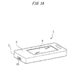
- Fig. 1 is a diagram illustrating the outer appearance of a blood glucose level measurement device 1 according to the present invention.
- the blood glucose level measurement device 1 is a portable measurement device configured in such a manner that a diabetic user can measure blood glucose on his/her own.
- the blood glucose level measurement device 1 has a long and thin chassis 2 (device main body), about the size of the user's palm.
- the device contributes thus to the blood glucose management of the user.
- Fig. 1A illustrates the configuration of the front side of the blood glucose level measurement device 1, and Fig. 1B the configuration of the rear side.
- a liquid crystal screen 4 for displaying measurement results and the like is provided on a panel 3 on the front side of the chassis 2.
- a test piece insertion groove 10 (corresponding to the fitting-removal section according to the present invention), into which there is inserted (as illustrated in Fig. 5 below) a test piece for measurement used in the blood glucose level measurement device 1, is provided at an end portion of the chassis 2.
- the test piece comprises a sensor that reacts with glucose in the blood sampled from the user, and that outputs an electric signal.
- the user places some blood of his/her own on the sensor, whereupon the measurement is carried out by the blood glucose level measurement device 1.
- the sensor there can be used, for instance, a sensor that relies on glucose oxidase (GOD), as an oxidoreductase, and that employs a hydrogen peroxide electrode as an electrode for signal output.
- GOD glucose oxidase
- the configuration of the test piece itself is a conventional one and not a core feature of the present invention, and hence a detailed explanation thereof will be omitted in the present specification.
- an operation button 7 for operating the blood glucose level measurement device 1 On the side face of the rear panel 3 of the chassis 2 there are provided, as illustrated in Fig. 1B , an operation button 7 for operating the blood glucose level measurement device 1, and a communication port B that connects, in a manner that enables communication, the blood glucose level measurement device 1 and an external device, for instance a computer or the like disposed outside the blood glucose level measurement device 1.
- the operation button 7 enables operations for all the processes that are performed in the blood glucose level measurement device 1, through a combination of various operations by the user on the operation button 7, for instance pressing, sliding, sustained pressing and the like.
- the operation button 7 corresponds to the operation unit according to the present invention.
- a control unit for controlling the various processes performed by the blood glucose level measurement device 1 is provided inside the latter.
- the main control units of the blood glucose level measurement device 1 there are provided a measurement control unit 20, a management control unit 30, a display control unit 40 and an external communication unit 50, as depicted in Fig. 2 .
- These control units are implemented by way of a computer program that is executed in a computer that is formed in the blood glucose level measurement device 1 and that comprises, for instance, a CPU, memory, a hard disk and the like, not shown.
- the above-described liquid crystal screen 4, operation button 7 and communication port 8 are appropriately connected to the control units illustrated in Fig. 2 .
- the control units of the blood glucose level measurement device 1 are formed by the measurement control unit 20 that performs mainly measurement control relating to the measurement of blood glucose levels; the management control unit 30 that performs management control relating to measurement results; the display control unit 40 that performs display control of the measurement results; and the external communication unit 50 that controls communication with the exterior of the measurement device.
- the blood glucose level measurement device 1 may be configured so as to include control units other than the above.
- the measurement control unit 20 has a test piece checking unit 21, a blood glucose level measurement unit 22, a measurement result storage unit 23 and a hypoglycemia alarm unit 24.
- the test piece checking unit 21 is a functional unit that checks whether the above-described test piece for blood glucose level measurement is set on the blood glucose level measurement device 1 in a state that enables measurement.
- the blood glucose level measurement unit 22 is a functional unit that measures a blood glucose level of the user on the basis of an output signal from the checked test piece.
- the measurement result storage unit 23 is a functional unit for saving and storing data on the results from the measurement performed by the blood glucose level measurement unit 22 in a storage device (memory) in the blood glucose level measurement device 1.
- the hypoglycemia alarm unit 24 is a functional unit that issues hypoglycemia alarm to the user when the measured results are lower than a standard range for an adequate blood glucose level.
- the management control unit 30 has a state flag setting unit 31, an elapsed time setting unit 32, and a parameter setting unit 33.
- the state flag setting unit 31 has the function of setting flags relating to the state of the body, upon blood glucose level measurement, that exerts an influence on the blood glucose level of the user. Management of the blood glucose level of the user can be performed efficiently thanks to such a function.
- state flags for post-exercise, pre-meal and post-meal are employed as flags that indicate the state of the body of the user. To set these state flags, the user operates the operation button 7, and follows the contents displayed on the liquid crystal screen 4.
- the user selects, through button operation, from among four state flags, namely a post-exercise flag, a pre-meal flag, a post-meal flag and no state flag.
- the state flag according to that selection is stored, in the blood glucose level measurement device 1, associated with a measured blood glucose level.
- These state flags relate to states of the body that are strongly linked to the blood glucose level of the user. Therefore, associating state flags to the measured blood glucose level is extremely useful for the management of blood glucose levels.
- the display control unit 40 is a control unit for displaying, for instance, measurement results of blood glucose level by the measurement control unit 20, as well as state flags set by the management control unit 30, on a liquid crystal screen of the blood glucose level measurement device 1.
- Fig. 3 illustrates an example of display on the liquid crystal screen 4 as performed by the display control unit 40.
- the icons and numerical values are displayed collectively in the display screen example.
- a graph display region DR1 being a rectangular display region at which measurement results are displayed in the form of a graph, is formed at the left of the liquid crystal screen 4.
- the icons displayed at the icon display region DR3 include an icon "HYPO" for hypoglycemia alarm, as well as a post-exercise flag icon Ic1, a pre-meal flag icon Ic2, a post-meal flag first icon Ic3 and a second icon Ic4, as the above-described state flags.
- An elapsed time after meal Et is displayed, alongside the post-meal flag first and second icons, on the icon display region DR3.
- the display control itself of the display control unit 40 is not a core feature of the present invention, and hence a detailed explanation thereof will be omitted in the present specification.
- the user can set information relating to the food intake amount ingested during a meal in the blood glucose level measurement device 1 according to the present example. Specifically, the user can subjectively select, as the food intake amount, one from among three benchmarks, namely 50%, 80% and 100%, where 100% denotes a full-stomach meal. In the blood glucose level measurement device 1 according to the present example, selection of this post-meal flag is displayed at the icon display region DR3 of Fig. 3 in the form of the post-meal flag first icon Ic3.
- Display of food intake amount is accomplished by modifying the number of bars that are displayed in the icon simultaneously with the display of the post-meal flag second icon Ic4.
- the number of bars is three (situation illustrated in Fig. 3 ), while for 80% and 50% of food intake amount the number of bars is two and one, respectively.
- the elapsed time setting unit 32 is a functional unit that sets the elapsed time from the point in time at which a meal is over, upon setting of the post-meal state flag in the state flag by setting unit 31. Prior to a measurement, the elapsed time setting unit 32 sets an elapsed time counter that counts automatically the elapsed time since the point in time at which a meal is over, and associates the time elapsed, counted by the counter, of the blood glucose level of the measurement results at that point in time. The elapsed time is displayed as an elapsed time after meal Et in the icon display region DR3 of Fig. 3 .
- the parameter setting unit 33 is a functional unit that sets various control parameters that are used by the blood glucose level measurement device 1. Examples of the parameters include, for instance, the time and date in the blood glucose level measurement device 1, as well as a container-unsealing date of a below-described test piece.
- the functional units in such a management control unit 30 allow the user to effectively manage, on his/her own, measurement results relating to blood glucose levels.
- the external communication unit 50 is a control unit for transmission, in particular of measurement results by the measurement control unit 20, and information such as state flags managed by the management control unit 30, to the exterior of the blood glucose level measurement device 1.
- communication control by the external communication unit 50 is not a core feature. Therefore, description is made only for the external communication function implemented by the external communication unit 50 in the present specification, and a detailed explanation thereof is omitted.
- Fig. 4 is an enlarged diagram of the outer appearance of the blood glucose level measurement device 1 in the vicinity of the test piece insertion groove 10.
- Fig. 5 is a top-view diagram of the blood glucose level measurement device 1 in a state where the front panel 3 is removed.
- Fig. 6 is a cross-sectional diagram along line A-A of Fig. 5 (the panel 3 is depicted as a broken line).
- a backlight 41 is provided at the rear face of the liquid crystal screen 4 of the blood glucose level measurement device 1.
- the backlight 41 has a plate-like shape, and emits light upon receiving power from a power source for blood glucose level measurement in the blood glucose level measurement device 1.
- the backlight 41 is an edge light-type backlight having a light source at an end portion side that is an opposite side to the test piece insertion groove 10, in the longitudinal direction of the blood glucose level measurement device 1.
- the backlight 41 corresponds to the light source section of the present invention.
- An illumination opening 45 is provided above (i.e. towards the device front side at which the liquid crystal screen 4 is disposed) the test piece insertion groove 10 that is provided on the side face of the chassis 2 in the longitudinal direction of the blood glucose level measurement device 1.
- the light guide member 42 is provided in the blood glucose level measurement device 1 in such a manner that an end 42a of the light guide member 42 is exposed at the illumination opening 45.
- the light guide member 42 has a thin, long shape, and has end portions 42a, 42b into/out of which light can enter/exit. The light guide member 42 allows light to be incident into one end and to exit through the other end.
- the lateral portion of the light guide member 42 (portion other than the end portions and that extends in the longitudinal direction) is preferably subjected to a surface treatment such that light incident into the light guide member 42 does not leak readily through the lateral portion.
- the light guide member 42 thus formed is disposed adjacent to the backlight in such a manner that light emitted by the backlight 41 can strike the end 42b of the light guide member 42, as illustrated in Fig. 5 and Fig. 6 .
- the light guide member 42 is also disposed in such a manner that the other end 42a is exposed out of the blood glucose level measurement device 1 at the illumination opening 45.
- the light guide member 42 is disposed in the blood glucose level measurement device 1 in such a manner so as to connect the backlight 41 of the liquid crystal screen 4 disposed at the center of the front side panel 3, as illustrated in Fig. 1A , with the illumination opening 45 disposed on a side of the chassis 2.
- the light guide member 42 is disposed in the blood glucose level measurement device 1 so as to slant slightly, i.e. in such a manner that the end 42b is positioned slightly higher than the end 42a in Fig. 6 .
- the direction of light that is guided within the light guide member 42 is defined thereby.
- this slanting causes the light from the end 42a to be irradiated downwards in Fig. 6 , i.e. towards the side at which the test piece is present.
- the range of light irradiation from the end 42a can be adjusted to some extent through adjustment of the inclination of the light guide member 42.
- a guide member 43 having a protrusion projecting slightly out of the device is disposed under the test piece insertion groove 10.
- the user can easily slip the test piece into the test piece insertion groove 10 thanks to the protrusion of the guide member 43.
- the test piece inserted into the test piece insertion groove 10 becomes electrically connected to the connection portion 44 provided at the back of the groove, there can take place the above-described checking of test piece insertion by the test piece checking unit 21, transmission of measurement results in the test piece to the device main body, and measurement of blood glucose level by the blood glucose level measurement unit 22.
- the configuration of the measurement device can be simplified, and consumption of current required for illumination can be reduced.
- This is preferable in terms of securing a power supply for driving the measurement device.
- the portable blood glucose level measurement device 1 combines the effects of securing driving power supply and enhancing user-friendliness. The desirability of the blood glucose level measurement device 1 in practice should therefore be appreciated.
- the backlight 41 and the light guide member 42 are configured separately, and are disposed adjacent to each other, but it is also possible, in an alternative configuration, to form the backlight 41 and the light guide member 42 continuously in the form of a single slab.
- the backlight 41 emits light in response to an operation of the operation button 7 by the user.
- the backlight 41 can be lighted up as a result of pushing, sliding or the like, of the operation button 7.
- light emitted by the backlight 41 is transmitted via the light guide member 42 and is irradiated through the illumination opening 45.
- the operation button 7 is a button for transmission of instructions by the user for performing the various controls described above based on Fig. 2 , and is also a button for triggering irradiation of light from the illumination opening 45.
- the explanation of the above-described examples deals with illumination from the illumination opening 45 upon fitting of the test piece.
- the above-described illumination can take place, through operation of the operation button 7, also upon removal of the fitted test piece.
- Blood of the user may be placed on the test piece before fitting of the test piece or after fitting of the test piece.
- the test piece is fitted to the test piece insertion groove 10, and in that state, the user operates the operation button 7, whereupon the backlight 41 emits light that is irradiated through the illumination opening 45, to illuminate thereby the site at which the blood is placed on the test piece.
- the user can perform as a result the blood placement operation in an easy manner.
- the backlight 41 may be caused to emit light automatically at the same time that the test piece is inserted into the test piece insertion groove 10, or at a timing after a predetermined time has elapsed after fitting of the test piece, irrespective of the presence or absence of illumination during placement on the test piece.
- the backlight 41 In terms of controlling power consumption, it is not desirable for the backlight 41 to be lighted up at all times. For instance, power consumption in the backlight 41 can be curbed by controlling the backlight 41 in such a manner that the latter lights up after a predetermined time has elapsed since some operation of the operation button 7 by the user.
- the luminous intensity at the illumination opening 45 ranges preferably from 1 ⁇ Cd/m 2 to 10000 Cd/m 2 . More preferably from 1 mCd/m 2 to 2000 Cd/m 2 , and yet more preferably from 1 Cd/m 2 to 100 Cd/m 2 .
- FIG. 7 and Fig. 8 are cross-sectional diagrams illustrating relevant portions of a measurement device 1 according to the present variation.
- Fig. 7 is a diagram illustrating schematically a horizontal cross section (transversal cross section) of the blood glucose level measurement device 1.
- Fig. 8 is a diagram illustrating schematically a vertical cross section (longitudinal cross section) of the measurement device 1.
- the blood glucose level measurement device 1 according to the present variation comprises an operation unit 46 for operating the blood glucose level measurement device 1, a light source 47 for light-up of the operation unit 46 , and a light guide member 42' for guiding light from the light source 47 to a test piece insertion groove 10'.
- Fig. 7 illustrates the plan-view arrangement relationship between the operation unit 46, the light source 47 and the light guide member 42' of the blood glucose level measurement device 1.
- Fig. 8 illustrates a perpendicular cross section of Fig. 7 .
- the operation unit 46 is provided in a panel 3' that makes up the front face of a chassis of the blood glucose level measurement device 1.
- the light source 47 for irradiating the operation unit 46 is disposed on a base 49 in the blood glucose level measurement device 1, below the operation unit 46.
- the light guide member 42' is formed between the light source 47 and the test piece insertion groove 10', in such a manner that light from the light source 47 is guided to the test piece insertion groove 10'.
- the operation unit 46 is formed of a material that is brightly defined by the light emitted by the light source 47.
- the operation unit 46 is lighted-up through light emission by the light source 47, and at the same time, the light from the light source 47 is guided to the test piece insertion groove 10' by way of the light guide member 92'.
- the blood glucose level measurement device 1 may have a light source for irradiation of the above-described communication port 8, and there is provided a light guide member that guides light from this light source to the test piece insertion groove. So long as light from a light source is guided by way of a light guide member, such a configuration is found to lie within the scope of the present invention, even if the light source is not a light source provided for test piece insertion, as in the above-described variations.
- An exposed end portion of the light guide member may be arranged arbitrarily so as to irradiate light that is guided from the light source, by way of the light guide member, onto a position in the vicinity of the operation button 7 and/or the communication port 8.
- the operation of the operation button 7 by the user, as well as access to the communication port 8, can be assisted thereby.
Abstract

Description
- The present invention relates to a measurement device that measures biological information of a user, to an illumination method in a biological information measurement device, and to a biological information measurement method.
- The operability of measurement devices for measuring blood glucose levels, as well as the preparations required for the measurements, among other considerations, are significant issues to users such as diabetic patients who have to measure blood glucose levels and who must control food intake amounts and exercise amounts, as instances of health management. Therefore, portable measurement devices have been developed in order for users to be able to measure blood glucose levels comparatively easily in the daily life. These devices incorporate various functions that help the user manage blood glucose levels.
- Ordinarily, sensors in portable measurement devices are disposable: upon each measurement, a new sensor is fitted to the sensor, and blood to be measured is placed on the sensor. In order to facilitate measurements in comparatively dark rooms, for instance during nighttime, measurement devices, which incorporate an illumination device that illuminates the vicinity of a region at which the blood is placed, have been developed (for instance, Japanese Patent Application Publication No.
2006-284981 2006-284481 - When considering a situation where devices for measuring biological information such as blood glucose levels are used, it is found that such devices are used not only during daytime, but are also often used in comparatively dark surroundings, for instance during nighttime. Therefore, user-friendliness upon fitting/removal of the sensor for biological information measurement to/from the device main body is directly linked to operability of the measurement device itself. Meanwhile, especially for portable measurement devices, limiting to the utmost the power consumption in the portable measurement device itself is a further requirement, in response to growing environmental awareness.
- Thus, user-friendliness has been enhanced in conventional art through arrangement, in the measurement device, of an illumination device (light-emitting diode or the like) for illumination of a blood-sampling site. However, the illumination device entails conversely greater power consumption and a shorter life of the power supply of the portable measurement device.
- In the light of the above problems, it is an object of embodiments of the invention to provide, in a measurement device that measures biological information of a user, an illumination function that improves user-friendliness, while limiting as much as possible increases in power consumption in the measurement device.
- According to one aspect, the present invention provides a biological information measurement device in which light emitted by a light source section that already functions as a light source for any component of the device, is guided, by way of a light guide member, to a predetermined site to/from which a sensor for measurements is fitted/removed. As a result, it becomes unnecessary to provide a new light source for sensor fitting/removal, and thus wasteful increases in power consumption in the measurement device are avoided.
- Specifically, embodiments provide a biological information measurement device that measures biological information of a user, including a device main body; a fitting-removal section which is provided in the device main body, and to/from which a sensor that measures the biological information is fitted/removed; a light source section that is provided within the device main body at a position spaced apart from the fitting-removal section and that functions as a light source for components of the biological information measurement device other than the fitting-removal section; and a light guide member that guides light emitted by the light source section to a predetermined position in the vicinity of the fitting-removal section to/from which the sensor is fitted/removed.
- In the biological information measurement device according to this aspect, for instance, the sensor for measurements is fitted to the fitting-removal section of the device main body. In that state, a sample to be measured is, for instance, placed on or absorbed by the sensor, as a result of which a signal relating to the biological information to be measured is transmitted by the sensor to the device main body. Biological information ultimately required by the device main body is generated on the basis of that signal. To measure the desired biological information using a biological information measurement device having such a configuration, the user must fit the sensor to the fitting-removal section, and remove the sensor once the measurement is over. Therefore, the operations of fitting and removing the sensor to/from the device main body upon operation of the measurement device by the user are found to be factors that significantly influence both the user-friendliness and the operability of the measurement device.
- In the biological information measurement device, therefore, the light source section functions as a light source for components of the biological information measurement device other than the fitting-removal section, at a position spaced apart from the fitting-removal section. The light source section is built-in as a component already present in the biological information measurement device, and not a new component that is built into the device to solve the above-described problems. In the biological information measurement device, therefore, an already built-in component that functions as any light source corresponds to the above-described light source section.
- However, by arranging the light guide member between the light source section and a predetermined position in the vicinity of the fitting-removal section, it becomes now possible to guide light from a light source section, not intended originally for illumination of the fitting-removal section, to the vicinity of the fitting-removal section, and to assist thereby fitting/removal of the sensor to/from the fitting-removal section. In particular, the light that is guided by the light guide member assists effectively the operation sensor fitting/removal operation by the user in a dimly-lit environment, so that light emission that accompanies such assistance does not consume power directly. Therefore, no unnecessary increase in power consumption is incurred by the biological information measurement device. The predetermined position may be any position from which light transmitted by the light guide member can be emitted and at which the sensor Litting/removal operations can be assisted. Such a predetermined position is for instance a position, suitable for the above-described assistance, in the vicinity of the fitting-removal section. The predetermined position may be the position of the fitting-removal section itself.
- The biological information measurement device may further include a display that displays biological information measured by way of the sensor. In this case, the light source section may be a backlight that functions as a light source for the display. The backlight is a light source for making it easier for the user to view the contents displayed on the display; i.e. the backlight is a component already built into the measurement device. In a biological information measurement device having such a configuration, therefore, light emitted by the backlight is guided to the predetermined position by the light guide member. As a result, illumination of the predetermined position can be secured without providing any new light source.
- In such a case, the fitting-removal section may be provided on a side face of the device main body; and the light guide member may have a length enabling light of the backlight to be guided to the predetermined position. That is, setting an appropriate length for the light guide member allows reliably conveying the light of the backlight to a distant position at which the fitting-removal section is provided.
- The abovementioned biological information measurement device may further include an operation unit for enabling a user to operate the biological information measurement device. In this case, the biological information measurement device may be configured so that, upon operation of the operation unit by the user, the light source section emits light and the light guide member guides the light to the predetermined position. In a case where the user operates the biological information measurement device via the operation unit, specifically, fitting of the sensor to the fitting-removal section and subsequent removal of the sensor therefrom can be made easier thanks to light emitted by a light-emitting section, upon contact with the operation unit.
- The biological information measurement device may be configured so that upon fitting of the sensor to the fitting-removal section, the light source section emits light and the light guide member guides the light to the predetermined position. In such a configuration, light is guided to a predetermined position, by way of a light guide member, after fitting of the sensor. Therefore, the user can perform more easily various manipulations on the fitted sensor, for instance placement of a biological sample. In that case, light may be emitted by the light source section simultaneously with fitting of the sensor to the fitting-removal section, or after fitting of the sensor.
- In the above-mentioned biological information measurement device, the biological information measurement device may be a device that measures a blood glucose level of a user, in which case a sensor for blood glucose level measurement, on which blood of the user is placed and which produces a current output according to a glucose level of the blood, may be fitted to/removed from the fitting-removal section. The biological information measurement device may be a user-portable device. The foregoing features are examples, and the biological information measurement device according to the present invention is not limited to those features.
- Another aspect of the present invention is an illumination method in a biological information measurement device. Specifically, the present invention also provides an illumination method in a biological information measurement device that measures biological information of a user and that has a device main body and a fitting-removal section to/from which a sensor that measures biological information of a user is fitted/removed from outside, the illumination method being a method for illuminating the vicinity of the fitting-removal section and including: a first step of causing light emission by a light source section that is provided within the device main body at a position spaced apart from the fitting-removal section and that functions as a light source for components of the biological information measurement device other than the fitting-removal section; and a second step of guiding light emitted by the light source section in the first step, to a predetermined position in the vicinity of the fitting-removal section to/from which the sensor is fitted/removed, by way of a light guide member that is provided between the light source section and the predetermined position. As is the case of the above-described biological information measurement device, in the illumination method according to the present invention as well illumination is provided during fitting/removal of the sensor, without providing any new light source for sensor fitting/removal. Therefore, device operability and user-friendliness can be enhanced without unnecessary rises in power consumption in the biological information measurement device. The technical ideas disclosed for the biological information measurement device apply in the same way to the illumination method according to the present invention.
- Another aspect of the present invention is a biological information measurement method that uses a biological information measurement device. Specifically, the present invention also provides a method for measuring biological information of a user in a biological information measurement device that has a device main body and a fitting-removal section to/from which a sensor that measures biological information of a user is fitted/removed from outside, the method including: a light emission step of causing light emission by a light source section that is provided within the device main body at a position spaced apart from the fitting-removal section and that functions as a light source for components of the biological information measurement device other than the fitting-removal section; and a fitting step of fitting the sensor to the fitting-removal section in a state where the light source section in the light emission step is emitting light to a light guide member that is provided between the light source section and a predetermined position in the vicinity of the fitting-removal section. In the measurement method according to the present invention as well, illumination at the predetermined position is carried out in the same manner as described above. This facilitates fitting/removal of the sensor to/from the device main body.
- A further aspect of the present invention is another biological information measurement method. Specifically, the present invention also provides a method for measuring biological information of a user in a biological information measurement device that has a device main body and a fitting-removal section to/from which a sensor that measures biological information of a user is fitted/removed from outside, the method including: a fitting step of fitting the sensor to the fitting-removal section; and a light emission step of, upon fitting of the sensor in the fitting step, causing a light source section that is provided within the device main body at a position spaced apart from the fitting-removal section and that functions as a light source for components of the biological information measurement device other than the fitting-removal section, to emit light to a light guide member that is provided between the light source section and a predetermined position in the vicinity of the fitting-removal section. By causing light to be emitted to the light guide member at the point in time at which the sensor is fitted, thus, light can be guided to the predetermined position, by way of the light guide member, also after fitting of the sensor. Therefore, the user can perform more easily various manipulations on the fitted sensor, for instance placement of a biological sample. In that case, light is emitted by the light source section at a timing simultaneously with fitting of the sensor to the fitting-removal section, or after fitting of the sensor.
- The measurement device that measures biological information of a user provides thus an illumination function that improves user friendliness and that allows limiting, as much as possible, increases in power consumption in the measurement device.
-
-
Fig. 1A is a first diagram illustrating the outer configuration of a blood glucose level measurement device according to the present invention; -
Fig. 1B is a second diagram illustrating the outer configuration of a blood glucose level measurement device according to the present invention; -
Fig. 2 is a functional block diagram of each functional unit formed in the blood glucose level measurement device illustrated inFig. 1 ; -
Fig. 3 is a diagram illustrating a display example of a liquid crystal screen in the blood glucose level measurement device illustrated inFig. 1 ; -
Fig. 4 is an enlarged diagram of the vicinity of a test piece insertion groove in the blood glucose level measurement device illustrated inFig. 1 ; -
Fig. 5 is a top-view diagram of the blood glucose level measurement device illustrated inFig. 1 , with a front panel removed; -
Fig. 6 is a cross-sectional diagram, along A-A, of the blood glucose level measurement device illustrated inFig. 5 ; -
Fig. 7 is diagram illustrating schematically a horizontal cross section of a blood glucose level measurement device according to a variation; and -
Fig. 8 is diagram illustrating schematically a vertical cross section of a blood glucose level measurement device according to a variation. - An explanation follows next, with reference to accompanying drawings, on a blood glucose level measurement device that corresponds to the biological information measurement device according to an embodiment of the present invention. The features in the embodiments described below are illustrative in nature, and the present invention is not limited to the features of the embodiments.
-
Fig. 1 is a diagram illustrating the outer appearance of a blood glucoselevel measurement device 1 according to the present invention. The blood glucoselevel measurement device 1 is a portable measurement device configured in such a manner that a diabetic user can measure blood glucose on his/her own. As illustrated in the figure, the blood glucoselevel measurement device 1 has a long and thin chassis 2 (device main body), about the size of the user's palm. As a result, operability by the user is enhanced, and measurement results can be managed and displayed, quickly and appropriately, as described below. The device contributes thus to the blood glucose management of the user. - Specifically,
Fig. 1A illustrates the configuration of the front side of the blood glucoselevel measurement device 1, andFig. 1B the configuration of the rear side. Aliquid crystal screen 4 for displaying measurement results and the like is provided on apanel 3 on the front side of thechassis 2. A test piece insertion groove 10 (corresponding to the fitting-removal section according to the present invention), into which there is inserted (as illustrated inFig. 5 below) a test piece for measurement used in the blood glucoselevel measurement device 1, is provided at an end portion of thechassis 2. The test piece comprises a sensor that reacts with glucose in the blood sampled from the user, and that outputs an electric signal. To perform a blood glucose level measurement, the user places some blood of his/her own on the sensor, whereupon the measurement is carried out by the blood glucoselevel measurement device 1. As the sensor there can be used, for instance, a sensor that relies on glucose oxidase (GOD), as an oxidoreductase, and that employs a hydrogen peroxide electrode as an electrode for signal output. The configuration of the test piece itself is a conventional one and not a core feature of the present invention, and hence a detailed explanation thereof will be omitted in the present specification. - On the side face of the
rear panel 3 of thechassis 2 there are provided, as illustrated inFig. 1B , anoperation button 7 for operating the blood glucoselevel measurement device 1, and a communication port B that connects, in a manner that enables communication, the blood glucoselevel measurement device 1 and an external device, for instance a computer or the like disposed outside the blood glucoselevel measurement device 1. Theoperation button 7 enables operations for all the processes that are performed in the blood glucoselevel measurement device 1, through a combination of various operations by the user on theoperation button 7, for instance pressing, sliding, sustained pressing and the like. Theoperation button 7 corresponds to the operation unit according to the present invention. - A control unit for controlling the various processes performed by the blood glucose
level measurement device 1 is provided inside the latter. As the main control units of the blood glucoselevel measurement device 1 there are provided ameasurement control unit 20, amanagement control unit 30, adisplay control unit 40 and anexternal communication unit 50, as depicted inFig. 2 . These control units are implemented by way of a computer program that is executed in a computer that is formed in the blood glucoselevel measurement device 1 and that comprises, for instance, a CPU, memory, a hard disk and the like, not shown. The above-describedliquid crystal screen 4,operation button 7 and communication port 8 are appropriately connected to the control units illustrated inFig. 2 . As a result, there are executed various program processes relating to, for instance, display of measurement results to the user, transmission of operation instructions from the user to the measurement device, and outward communication of data stored in the blood glucoselevel measurement device 1. The features of the control units of the blood glucoselevel measurement device 1 of the present invention are explained further on. - As described above, the control units of the blood glucose
level measurement device 1 are formed by themeasurement control unit 20 that performs mainly measurement control relating to the measurement of blood glucose levels; themanagement control unit 30 that performs management control relating to measurement results; thedisplay control unit 40 that performs display control of the measurement results; and theexternal communication unit 50 that controls communication with the exterior of the measurement device. However, the blood glucoselevel measurement device 1 may be configured so as to include control units other than the above. Specifically, themeasurement control unit 20 has a testpiece checking unit 21, a blood glucose level measurement unit 22, a measurementresult storage unit 23 and ahypoglycemia alarm unit 24. The testpiece checking unit 21 is a functional unit that checks whether the above-described test piece for blood glucose level measurement is set on the blood glucoselevel measurement device 1 in a state that enables measurement. The blood glucose level measurement unit 22 is a functional unit that measures a blood glucose level of the user on the basis of an output signal from the checked test piece. The measurementresult storage unit 23 is a functional unit for saving and storing data on the results from the measurement performed by the blood glucose level measurement unit 22 in a storage device (memory) in the blood glucoselevel measurement device 1. Thehypoglycemia alarm unit 24 is a functional unit that issues hypoglycemia alarm to the user when the measured results are lower than a standard range for an adequate blood glucose level. - The
management control unit 30 has a stateflag setting unit 31, an elapsedtime setting unit 32, and aparameter setting unit 33. The stateflag setting unit 31 has the function of setting flags relating to the state of the body, upon blood glucose level measurement, that exerts an influence on the blood glucose level of the user. Management of the blood glucose level of the user can be performed efficiently thanks to such a function. In the present example, state flags for post-exercise, pre-meal and post-meal, are employed as flags that indicate the state of the body of the user. To set these state flags, the user operates theoperation button 7, and follows the contents displayed on theliquid crystal screen 4. Specifically, the user selects, through button operation, from among four state flags, namely a post-exercise flag, a pre-meal flag, a post-meal flag and no state flag. The state flag according to that selection is stored, in the blood glucoselevel measurement device 1, associated with a measured blood glucose level. These state flags relate to states of the body that are strongly linked to the blood glucose level of the user. Therefore, associating state flags to the measured blood glucose level is extremely useful for the management of blood glucose levels. - Display of these state flags on the
liquid crystal screen 4 is accomplished by way of thedisplay control unit 40. Thedisplay control unit 40 is a control unit for displaying, for instance, measurement results of blood glucose level by themeasurement control unit 20, as well as state flags set by themanagement control unit 30, on a liquid crystal screen of the blood glucoselevel measurement device 1.Fig. 3 illustrates an example of display on theliquid crystal screen 4 as performed by thedisplay control unit 40. To facilitate the explanation, the icons and numerical values are displayed collectively in the display screen example. A graph display region DR1, being a rectangular display region at which measurement results are displayed in the form of a graph, is formed at the left of theliquid crystal screen 4. At the center there is formed a measured numerical value display region DR2 at which measured blood glucose levels and the like are displayed. An icon display region DR3 at which there are displayed icons having various meanings, as well as a predetermined elapsed time, is formed around the measured numerical value display region DR2. The icons displayed at the icon display region DR3 include an icon "HYPO" for hypoglycemia alarm, as well as a post-exercise flag icon Ic1, a pre-meal flag icon Ic2, a post-meal flag first icon Ic3 and a second icon Ic4, as the above-described state flags. An elapsed time after meal Et is displayed, alongside the post-meal flag first and second icons, on the icon display region DR3. The display control itself of thedisplay control unit 40 is not a core feature of the present invention, and hence a detailed explanation thereof will be omitted in the present specification. - In a case where the state flag set by the state
flag setting unit 31 is a post-meal flag, the user can set information relating to the food intake amount ingested during a meal in the blood glucoselevel measurement device 1 according to the present example. Specifically, the user can subjectively select, as the food intake amount, one from among three benchmarks, namely 50%, 80% and 100%, where 100% denotes a full-stomach meal. In the blood glucoselevel measurement device 1 according to the present example, selection of this post-meal flag is displayed at the icon display region DR3 ofFig. 3 in the form of the post-meal flag first icon Ic3. Display of food intake amount is accomplished by modifying the number of bars that are displayed in the icon simultaneously with the display of the post-meal flag second icon Ic4. In a case, for instance, of 100% food intake amount, the number of bars is three (situation illustrated inFig. 3 ), while for 80% and 50% of food intake amount the number of bars is two and one, respectively. By associating thus data relating to food intake amount with post-meal flags, the user can learn which meal amount corresponds to the measured blood glucose level. The user can grasp thus the relationship between food intake amount and blood glucose level, so that health management by the user relating to blood glucose levels is made easier in terms of, for instance, adjustment of food intake amount. - The elapsed
time setting unit 32 is a functional unit that sets the elapsed time from the point in time at which a meal is over, upon setting of the post-meal state flag in the state flag by settingunit 31. Prior to a measurement, the elapsedtime setting unit 32 sets an elapsed time counter that counts automatically the elapsed time since the point in time at which a meal is over, and associates the time elapsed, counted by the counter, of the blood glucose level of the measurement results at that point in time. The elapsed time is displayed as an elapsed time after meal Et in the icon display region DR3 ofFig. 3 . Thereby, the user can check, in addition to the food intake amount, how long after the end of a meal the measured blood glucose level corresponds to. This feature further facilitates health management relating to blood glucose levels. Theparameter setting unit 33 is a functional unit that sets various control parameters that are used by the blood glucoselevel measurement device 1. Examples of the parameters include, for instance, the time and date in the blood glucoselevel measurement device 1, as well as a container-unsealing date of a below-described test piece. The functional units in such amanagement control unit 30 allow the user to effectively manage, on his/her own, measurement results relating to blood glucose levels. - The
external communication unit 50 is a control unit for transmission, in particular of measurement results by themeasurement control unit 20, and information such as state flags managed by themanagement control unit 30, to the exterior of the blood glucoselevel measurement device 1. In the blood glucoselevel measurement device 1 of the present invention, communication control by theexternal communication unit 50 is not a core feature. Therefore, description is made only for the external communication function implemented by theexternal communication unit 50 in the present specification, and a detailed explanation thereof is omitted. - An explanation follows next, on the basis of
Fig. 4 to Fig. 6 , on the area of the testpiece insertion groove 10 at which a test piece for blood glucose level measurement is inserted in the blood glucoselevel measurement device 1.Fig. 4 is an enlarged diagram of the outer appearance of the blood glucoselevel measurement device 1 in the vicinity of the testpiece insertion groove 10.Fig. 5 is a top-view diagram of the blood glucoselevel measurement device 1 in a state where thefront panel 3 is removed.Fig. 6 is a cross-sectional diagram along line A-A ofFig. 5 (thepanel 3 is depicted as a broken line). Abacklight 41 is provided at the rear face of theliquid crystal screen 4 of the blood glucoselevel measurement device 1. Thebacklight 41 has a plate-like shape, and emits light upon receiving power from a power source for blood glucose level measurement in the blood glucoselevel measurement device 1. Thebacklight 41 is an edge light-type backlight having a light source at an end portion side that is an opposite side to the testpiece insertion groove 10, in the longitudinal direction of the blood glucoselevel measurement device 1. Thebacklight 41 corresponds to the light source section of the present invention. - An
illumination opening 45 is provided above (i.e. towards the device front side at which theliquid crystal screen 4 is disposed) the testpiece insertion groove 10 that is provided on the side face of thechassis 2 in the longitudinal direction of the blood glucoselevel measurement device 1. Thelight guide member 42 is provided in the blood glucoselevel measurement device 1 in such a manner that anend 42a of thelight guide member 42 is exposed at theillumination opening 45. Thelight guide member 42 has a thin, long shape, and hasend portions light guide member 42 allows light to be incident into one end and to exit through the other end. The lateral portion of the light guide member 42 (portion other than the end portions and that extends in the longitudinal direction) is preferably subjected to a surface treatment such that light incident into thelight guide member 42 does not leak readily through the lateral portion. Thelight guide member 42 thus formed is disposed adjacent to the backlight in such a manner that light emitted by thebacklight 41 can strike theend 42b of thelight guide member 42, as illustrated inFig. 5 andFig. 6 . Thelight guide member 42 is also disposed in such a manner that theother end 42a is exposed out of the blood glucoselevel measurement device 1 at theillumination opening 45. Specifically, thelight guide member 42 is disposed in the blood glucoselevel measurement device 1 in such a manner so as to connect thebacklight 41 of theliquid crystal screen 4 disposed at the center of thefront side panel 3, as illustrated inFig. 1A , with theillumination opening 45 disposed on a side of thechassis 2. - As illustrated in
Fig. 6 , thelight guide member 42 is disposed in the blood glucoselevel measurement device 1 so as to slant slightly, i.e. in such a manner that theend 42b is positioned slightly higher than theend 42a inFig. 6 . The direction of light that is guided within thelight guide member 42 is defined thereby. In the present example, this slanting causes the light from theend 42a to be irradiated downwards inFig. 6 , i.e. towards the side at which the test piece is present. Thus the range of light irradiation from theend 42a can be adjusted to some extent through adjustment of the inclination of thelight guide member 42. - A
guide member 43 having a protrusion projecting slightly out of the device is disposed under the testpiece insertion groove 10. The user can easily slip the test piece into the testpiece insertion groove 10 thanks to the protrusion of theguide member 43. Once the test piece inserted into the testpiece insertion groove 10 becomes electrically connected to theconnection portion 44 provided at the back of the groove, there can take place the above-described checking of test piece insertion by the testpiece checking unit 21, transmission of measurement results in the test piece to the device main body, and measurement of blood glucose level by the blood glucose level measurement unit 22. - In the blood glucose
level measurement device 1 having the above-described configuration, light from thebacklight 41, which is the light source for theliquid crystal screen 4, is transmitted by thelight guide member 42 and is irradiated to the outside of the device through theillumination opening 45. Theguide member 43 is positioned under theillumination opening 45, and hence the above illumination strikes the vicinity of the inlet portion of the testpiece insertion groove 10. As a result, fitting of the test piece to the blood glucoselevel measurement device 1 becomes easier. In particular, an illumination method that utilizes light from thebacklight 41, via thelight guide member 42, is very useful upon measurement of blood glucose levels in dimly-lit rooms, for instance at nighttime. No dedicated illumination device for test piece insertion is provided in the blood glucoselevel measurement device 1 according to the present invention. Instead, light from the backlight of theliquid crystal screen 4 is effectively used to a greater degree, thanks to thelight guide member 42. As a result, the configuration of the measurement device can be simplified, and consumption of current required for illumination can be reduced. This is preferable in terms of securing a power supply for driving the measurement device. In particular, the portable blood glucoselevel measurement device 1 combines the effects of securing driving power supply and enhancing user-friendliness. The desirability of the blood glucoselevel measurement device 1 in practice should therefore be appreciated. In the above-described examples, thebacklight 41 and thelight guide member 42 are configured separately, and are disposed adjacent to each other, but it is also possible, in an alternative configuration, to form thebacklight 41 and thelight guide member 42 continuously in the form of a single slab. - Herein, the
backlight 41 emits light in response to an operation of theoperation button 7 by the user. Specifically, thebacklight 41 can be lighted up as a result of pushing, sliding or the like, of theoperation button 7. Thereupon, light emitted by thebacklight 41 is transmitted via thelight guide member 42 and is irradiated through theillumination opening 45. That is, theoperation button 7 is a button for transmission of instructions by the user for performing the various controls described above based onFig. 2 , and is also a button for triggering irradiation of light from theillumination opening 45. - The explanation of the above-described examples deals with illumination from the
illumination opening 45 upon fitting of the test piece. However, the above-described illumination can take place, through operation of theoperation button 7, also upon removal of the fitted test piece. Blood of the user may be placed on the test piece before fitting of the test piece or after fitting of the test piece. In the latter case, the test piece is fitted to the testpiece insertion groove 10, and in that state, the user operates theoperation button 7, whereupon thebacklight 41 emits light that is irradiated through theillumination opening 45, to illuminate thereby the site at which the blood is placed on the test piece. The user can perform as a result the blood placement operation in an easy manner. In another method, thebacklight 41 may be caused to emit light automatically at the same time that the test piece is inserted into the testpiece insertion groove 10, or at a timing after a predetermined time has elapsed after fitting of the test piece, irrespective of the presence or absence of illumination during placement on the test piece. - In terms of controlling power consumption, it is not desirable for the
backlight 41 to be lighted up at all times. For instance, power consumption in thebacklight 41 can be curbed by controlling thebacklight 41 in such a manner that the latter lights up after a predetermined time has elapsed since some operation of theoperation button 7 by the user. In order to effectively support the operations of sensor fitting and removal by the user, the luminous intensity at theillumination opening 45 ranges preferably from 1 µCd/m2 to 10000 Cd/m2. more preferably from 1 mCd/m2 to 2000 Cd/m2, and yet more preferably from 1 Cd/m2 to 100 Cd/m2. - In the above-described example light from the
backlight 41, which is the light source for theliquid crystal screen 4, is used, by way of thelight guide member 42, as a light source for test piece insertion. However, if a light source other than thebacklight 41 is present in the blood glucoselevel measurement device 1, light emitted by that other light source may be guided to theillumination opening 45 by way of a light guide member. Such a configuration falls also within the scope of the invention. - A blood glucose
level measurement device 1 according to a variation of the present example will be explained next.Fig. 7 andFig. 8 are cross-sectional diagrams illustrating relevant portions of ameasurement device 1 according to the present variation.Fig. 7 is a diagram illustrating schematically a horizontal cross section (transversal cross section) of the blood glucoselevel measurement device 1.Fig. 8 is a diagram illustrating schematically a vertical cross section (longitudinal cross section) of themeasurement device 1. The blood glucoselevel measurement device 1 according to the present variation comprises anoperation unit 46 for operating the blood glucoselevel measurement device 1, alight source 47 for light-up of theoperation unit 46 , and a light guide member 42' for guiding light from thelight source 47 to a test piece insertion groove 10'.Fig. 7 illustrates the plan-view arrangement relationship between theoperation unit 46, thelight source 47 and the light guide member 42' of the blood glucoselevel measurement device 1.Fig. 8 illustrates a perpendicular cross section ofFig. 7 . - As illustrated in the figures, the
operation unit 46 is provided in a panel 3' that makes up the front face of a chassis of the blood glucoselevel measurement device 1. Thelight source 47 for irradiating theoperation unit 46 is disposed on a base 49 in the blood glucoselevel measurement device 1, below theoperation unit 46. As illustrated in the figures, the light guide member 42' is formed between thelight source 47 and the test piece insertion groove 10', in such a manner that light from thelight source 47 is guided to the test piece insertion groove 10'. In this example, theoperation unit 46 is formed of a material that is brightly defined by the light emitted by thelight source 47. Theoperation unit 46 is lighted-up through light emission by thelight source 47, and at the same time, the light from thelight source 47 is guided to the test piece insertion groove 10' by way of the light guide member 92'. In yet another variation, the blood glucoselevel measurement device 1 may have a light source for irradiation of the above-described communication port 8, and there is provided a light guide member that guides light from this light source to the test piece insertion groove. So long as light from a light source is guided by way of a light guide member, such a configuration is found to lie within the scope of the present invention, even if the light source is not a light source provided for test piece insertion, as in the above-described variations. An exposed end portion of the light guide member may be arranged arbitrarily so as to irradiate light that is guided from the light source, by way of the light guide member, onto a position in the vicinity of theoperation button 7 and/or the communication port 8. The operation of theoperation button 7 by the user, as well as access to the communication port 8, can be assisted thereby.
Claims (10)
- A biological information measurement device that
measures biological information of a user, comprising:a device main body;a fitting-removal section which is provided in the device main body, and to/from which a sensor that measures the biological information can be fitted/removed;a light source section that is provided within the device main body at a position spaced apart from the fitting-removal section and that functions as a light source for components of the biological information measurement device other than the fitting-removal section; anda light guide member that guides light emitted by the light source section to a predetermined position in the vicinity of the fitting-removal section to/from which the sensor can be fitted/removed. - The biological information measurement device according to claim 1, further comprising:a display that displays biological information measured by way of the sensor,wherein the light source section is a backlight that functions as a light source for the display.
- The biological information measurement device according to claim 2,
wherein the fitting-removal section is provided on a side face of the device main body, and
the light guide member has a length enabling light of the backlight to be guided to the predetermined position. - The biological information measurement device according to any one of claims 1 to 3, further comprising:an operation unit for enabling a user to operate the biological information measurement device,wherein upon operation of the operation unit by the user, the light source section emits light and the light guide member guides the light to the predetermined position.
- The biological information measurement device according to claim 4,
wherein upon fitting of the sensor to the fitting-removal section, the light source section emits light and the light guide member guides the light to the predetermined position. - The biological information measurement device according to any one of claims 1 to 5,
wherein the biological information measurement device is a device that measures a blood glucose level of a user, and
a sensor for blood glucose level measurement, on which blood of the user can be placed and which produces a current output according to a glucose level of the blood, can be fitted to/removed from the fitting-removal section. - The biological information measurement device according to any one of claims 1 to 6,
wherein the biological information measurement device is a user-portable device. - An illumination method in a biological information measurement device that measures biological information of a user and that has a device main body and a fitting-removal section to/from which a sensor that measures biological information of a user is fitted/removed from outside, the illumination method being a method for illuminating the vicinity of the fitting-removal section and comprising:a first step of causing light emission by a light source section that is provided within the device main body at a position spaced apart from the fitting-removal section and that functions as a light source for components of the biological information measurement device other than the fitting-removal section; anda second step of guiding light emitted by the light source section in the first step, to a predetermined position in the vicinity of the fitting-removal section to/from which the sensor is fitted/removed, by way of a light guide member that is provided between the light source section and the predetermined position.
- A method for measuring biological information of a user in a biological information measurement device that has a device main body and a fitting-removal section to/from which a sensor that measures biological information of a user is fitted/removed from outside, the method comprising:a light emission step of causing light emission by a light source section that is provided within the device main body at a position spaced apart from the fitting-removal section and that functions as a light source for components of the biological information measurement device other than the fitting-removal section; anda fitting step of fitting the sensor to the fitting-removal section in a state where the light source section in the light emission step is emitting light to a light guide member that is provided between the light source section and a predetermined position in the vicinity of the fitting-removal section.
- A method for measuring biological information of a user in a biological information measurement device that has a device main body and a fitting-removal section to/from which a sensor that measures biological information of a user is fitted/removed from outside, the method comprising:a fitting step of fitting the sensor to the fitting-removal section; anda light emission step of, upon fitting of the sensor in the fitting step, causing a light source section that is provided within the device main body at a position spaced apart from the fitting-removal section and that functions as a light source for components of the biological information measurement device other than the fitting-removal section, to emit light to a light guide member that is provided between the light source section and a predetermined position in the vicinity of the fitting-removal section.
Applications Claiming Priority (2)
| Application Number | Priority Date | Filing Date | Title |
|---|---|---|---|
| JP2010093571 | 2010-04-14 | ||
| JP2011057911A JP2011237408A (en) | 2010-04-14 | 2011-03-16 | Biological information measuring device, lighting method in the same and biological information measuring method |
Publications (2)
| Publication Number | Publication Date |
|---|---|
| EP2377465A1 true EP2377465A1 (en) | 2011-10-19 |
| EP2377465B1 EP2377465B1 (en) | 2014-08-27 |
Family
ID=44176330
Family Applications (1)
| Application Number | Title | Priority Date | Filing Date |
|---|---|---|---|
| EP11162484.7A Active EP2377465B1 (en) | 2010-04-14 | 2011-04-14 | Biological information measurement device, illumination method in a biological information measurement device, and biological information measurement method |
Country Status (5)
| Country | Link |
|---|---|
| US (1) | US20110257533A1 (en) |
| EP (1) | EP2377465B1 (en) |
| JP (1) | JP2011237408A (en) |
| KR (1) | KR20110115092A (en) |
| CN (1) | CN102279155A (en) |
Cited By (10)
| Publication number | Priority date | Publication date | Assignee | Title |
|---|---|---|---|---|
| US8465977B2 (en) | 2008-07-22 | 2013-06-18 | Roche Diagnostics Operations, Inc. | Method and apparatus for lighted test strip |
| US8894262B2 (en) | 2013-03-11 | 2014-11-25 | Roche Diagnostic Operations, Inc. | Blood glucose test strip illumination device and method |
| US9233204B2 (en) | 2014-01-31 | 2016-01-12 | Aseko, Inc. | Insulin management |
| US9483619B2 (en) | 2012-09-11 | 2016-11-01 | Aseko, Inc. | Means and method for improved glycemic control for diabetic patients |
| US9486580B2 (en) | 2014-01-31 | 2016-11-08 | Aseko, Inc. | Insulin management |
| US9886556B2 (en) | 2015-08-20 | 2018-02-06 | Aseko, Inc. | Diabetes management therapy advisor |
| US9892234B2 (en) | 2014-10-27 | 2018-02-13 | Aseko, Inc. | Subcutaneous outpatient management |
| US9897565B1 (en) | 2012-09-11 | 2018-02-20 | Aseko, Inc. | System and method for optimizing insulin dosages for diabetic subjects |
| US10036709B2 (en) | 2014-05-20 | 2018-07-31 | Roche Diabetes Care, Inc. | BG meter illuminated test strip |
| US11081226B2 (en) | 2014-10-27 | 2021-08-03 | Aseko, Inc. | Method and controller for administering recommended insulin dosages to a patient |
Families Citing this family (8)
| Publication number | Priority date | Publication date | Assignee | Title |
|---|---|---|---|---|
| JP5473862B2 (en) * | 2010-10-29 | 2014-04-16 | アークレイ株式会社 | Analysis equipment |
| JP5762570B2 (en) * | 2011-12-27 | 2015-08-12 | パナソニックヘルスケアホールディングス株式会社 | Biological sample measuring device |
| GB2513157B (en) * | 2013-04-17 | 2016-01-06 | Lifescan Scotland Ltd | Hand-held test meter with display illumination adjustment circuit block |
| JP6455425B2 (en) * | 2013-05-10 | 2019-01-23 | ニプロ株式会社 | measuring device |
| USD752758S1 (en) * | 2013-09-11 | 2016-03-29 | Samsung Electronics Co., Ltd. | Blood glucose meter |
| JP1519885S (en) * | 2014-06-10 | 2015-03-23 | ||
| EP3723611A4 (en) * | 2017-12-14 | 2021-11-03 | Essenlix Corporation | Improved optical transmission sample holder and analysis, particularly for hemoglobin |
| TWI707662B (en) * | 2019-09-12 | 2020-10-21 | 華廣生技股份有限公司 | Physiological sensing apparatus for reading a strip |
Citations (4)
| Publication number | Priority date | Publication date | Assignee | Title |
|---|---|---|---|---|
| WO2001008551A2 (en) * | 1999-07-28 | 2001-02-08 | Abbott Laboratories | Luminous glucose monitoring device |
| JP2006284481A (en) | 2005-04-04 | 2006-10-19 | National Institute Of Advanced Industrial & Technology | Detection part of biosensor |
| JP2006284981A (en) | 2005-04-01 | 2006-10-19 | Seiko Epson Corp | Image display device, method, and program |
| EP2103251A1 (en) * | 2008-03-21 | 2009-09-23 | Lifescan Scotland Limited | Analyte testing method and system |
Family Cites Families (5)
| Publication number | Priority date | Publication date | Assignee | Title |
|---|---|---|---|---|
| US108551A (en) * | 1870-10-25 | Improvement in horse hay-foxks | ||
| JP4085137B2 (en) * | 1998-02-20 | 2008-05-14 | アークレイ株式会社 | Biosensor system |
| US7444173B2 (en) * | 2000-12-29 | 2008-10-28 | Vertu Ltd. | Mobile telephone |
| JP5067228B2 (en) * | 2008-01-29 | 2012-11-07 | 株式会社Jvcケンウッド | Rotary joint |
| JP5286512B2 (en) * | 2008-04-18 | 2013-09-11 | 株式会社日立情報通信エンジニアリング | Laser annealing method and laser annealing apparatus |
-
2011
- 2011-03-16 JP JP2011057911A patent/JP2011237408A/en active Pending
- 2011-04-13 US US13/086,260 patent/US20110257533A1/en not_active Abandoned
- 2011-04-13 KR KR1020110034206A patent/KR20110115092A/en not_active Application Discontinuation
- 2011-04-14 CN CN2011100934775A patent/CN102279155A/en active Pending
- 2011-04-14 EP EP11162484.7A patent/EP2377465B1/en active Active
Patent Citations (4)
| Publication number | Priority date | Publication date | Assignee | Title |
|---|---|---|---|---|
| WO2001008551A2 (en) * | 1999-07-28 | 2001-02-08 | Abbott Laboratories | Luminous glucose monitoring device |
| JP2006284981A (en) | 2005-04-01 | 2006-10-19 | Seiko Epson Corp | Image display device, method, and program |
| JP2006284481A (en) | 2005-04-04 | 2006-10-19 | National Institute Of Advanced Industrial & Technology | Detection part of biosensor |
| EP2103251A1 (en) * | 2008-03-21 | 2009-09-23 | Lifescan Scotland Limited | Analyte testing method and system |
Cited By (45)
| Publication number | Priority date | Publication date | Assignee | Title |
|---|---|---|---|---|
| US8765482B2 (en) | 2008-07-22 | 2014-07-01 | Roche Diagnostics Operations, Inc. | Method and apparatus for lighted test strip |
| US8465977B2 (en) | 2008-07-22 | 2013-06-18 | Roche Diagnostics Operations, Inc. | Method and apparatus for lighted test strip |
| US9897565B1 (en) | 2012-09-11 | 2018-02-20 | Aseko, Inc. | System and method for optimizing insulin dosages for diabetic subjects |
| US10102922B2 (en) | 2012-09-11 | 2018-10-16 | Aseko, Inc. | Means and method for improved glycemic control for diabetic patients |
| US11131643B2 (en) | 2012-09-11 | 2021-09-28 | Aseko, Inc. | Method and system for optimizing insulin dosages for diabetic subjects |
| US9483619B2 (en) | 2012-09-11 | 2016-11-01 | Aseko, Inc. | Means and method for improved glycemic control for diabetic patients |
| US10629294B2 (en) | 2012-09-11 | 2020-04-21 | Aseko, Inc. | Means and method for improved glycemic control for diabetic patients |
| US10410740B2 (en) | 2012-09-11 | 2019-09-10 | Aseko, Inc. | Means and method for improved glycemic control for diabetic patients |
| US11733196B2 (en) | 2012-09-11 | 2023-08-22 | Aseko, Inc. | System and method for optimizing insulin dosages for diabetic subjects |
| US9965596B2 (en) | 2012-09-11 | 2018-05-08 | Aseko, Inc. | Means and method for improved glycemic control for diabetic patients |
| US9773096B2 (en) | 2012-09-11 | 2017-09-26 | Aseko, Inc. | Means and method for improved glycemic control for diabetic patients |
| US9811638B2 (en) | 2012-09-11 | 2017-11-07 | Aseko, Inc. | Means and method for improved glycemic control for diabetic patients |
| US8894262B2 (en) | 2013-03-11 | 2014-11-25 | Roche Diagnostic Operations, Inc. | Blood glucose test strip illumination device and method |
| US9486580B2 (en) | 2014-01-31 | 2016-11-08 | Aseko, Inc. | Insulin management |
| US9710611B2 (en) | 2014-01-31 | 2017-07-18 | Aseko, Inc. | Insulin management |
| US11783946B2 (en) | 2014-01-31 | 2023-10-10 | Aseko, Inc. | Method and system for insulin bolus management |
| US9965595B2 (en) | 2014-01-31 | 2018-05-08 | Aseko, Inc. | Insulin management |
| US10811133B2 (en) | 2014-01-31 | 2020-10-20 | Aseko, Inc. | System for administering insulin boluses to a patient |
| US11621074B2 (en) | 2014-01-31 | 2023-04-04 | Aseko, Inc. | Insulin management |
| US9604002B2 (en) | 2014-01-31 | 2017-03-28 | Aseko, Inc. | Insulin management |
| US11783945B2 (en) | 2014-01-31 | 2023-10-10 | Aseko, Inc. | Method and system for insulin infusion rate management |
| US9898585B2 (en) | 2014-01-31 | 2018-02-20 | Aseko, Inc. | Method and system for insulin management |
| US11857314B2 (en) | 2014-01-31 | 2024-01-02 | Aseko, Inc. | Insulin management |
| US11804300B2 (en) | 2014-01-31 | 2023-10-31 | Aseko, Inc. | Insulin management |
| US11081233B2 (en) | 2014-01-31 | 2021-08-03 | Aseko, Inc. | Insulin management |
| US10453568B2 (en) | 2014-01-31 | 2019-10-22 | Aseko, Inc. | Method for managing administration of insulin |
| US10535426B2 (en) | 2014-01-31 | 2020-01-14 | Aseko, Inc. | Insulin management |
| US9892235B2 (en) | 2014-01-31 | 2018-02-13 | Aseko, Inc. | Insulin management |
| US10255992B2 (en) | 2014-01-31 | 2019-04-09 | Aseko, Inc. | Insulin management |
| US9504789B2 (en) | 2014-01-31 | 2016-11-29 | Aseko, Inc. | Insulin management |
| US11490837B2 (en) | 2014-01-31 | 2022-11-08 | Aseko, Inc. | Insulin management |
| US9233204B2 (en) | 2014-01-31 | 2016-01-12 | Aseko, Inc. | Insulin management |
| US11158424B2 (en) | 2014-01-31 | 2021-10-26 | Aseko, Inc. | Insulin management |
| US11311213B2 (en) | 2014-01-31 | 2022-04-26 | Aseko, Inc. | Insulin management |
| US11468987B2 (en) | 2014-01-31 | 2022-10-11 | Aseko, Inc. | Insulin management |
| US10036709B2 (en) | 2014-05-20 | 2018-07-31 | Roche Diabetes Care, Inc. | BG meter illuminated test strip |
| US11081226B2 (en) | 2014-10-27 | 2021-08-03 | Aseko, Inc. | Method and controller for administering recommended insulin dosages to a patient |
| US10403397B2 (en) | 2014-10-27 | 2019-09-03 | Aseko, Inc. | Subcutaneous outpatient management |
| US11678800B2 (en) | 2014-10-27 | 2023-06-20 | Aseko, Inc. | Subcutaneous outpatient management |
| US11694785B2 (en) | 2014-10-27 | 2023-07-04 | Aseko, Inc. | Method and dosing controller for subcutaneous outpatient management |
| US10128002B2 (en) | 2014-10-27 | 2018-11-13 | Aseko, Inc. | Subcutaneous outpatient management |
| US9892234B2 (en) | 2014-10-27 | 2018-02-13 | Aseko, Inc. | Subcutaneous outpatient management |
| US9886556B2 (en) | 2015-08-20 | 2018-02-06 | Aseko, Inc. | Diabetes management therapy advisor |
| US11574742B2 (en) | 2015-08-20 | 2023-02-07 | Aseko, Inc. | Diabetes management therapy advisor |
| US10380328B2 (en) | 2015-08-20 | 2019-08-13 | Aseko, Inc. | Diabetes management therapy advisor |
Also Published As
| Publication number | Publication date |
|---|---|
| EP2377465B1 (en) | 2014-08-27 |
| US20110257533A1 (en) | 2011-10-20 |
| KR20110115092A (en) | 2011-10-20 |
| CN102279155A (en) | 2011-12-14 |
| JP2011237408A (en) | 2011-11-24 |
Similar Documents
| Publication | Publication Date | Title |
|---|---|---|
| EP2377465B1 (en) | Biological information measurement device, illumination method in a biological information measurement device, and biological information measurement method | |
| US9109926B2 (en) | Method and apparatus for providing power management in data communication systems | |
| EP2310849B1 (en) | Method and apparatus for lighted test strip | |
| US20110263959A1 (en) | Method of inputting data into an analyte testing device | |
| KR100504766B1 (en) | Blood glucose test meter having each measuring means at its both ends | |
| JP2011064596A (en) | Blood glucose meter | |
| JP6084568B2 (en) | Analyte monitor system | |
| JP6455425B2 (en) | measuring device | |
| KR20060119039A (en) | Blood glucose test meter of divide into three for multiple connection | |
| JP2007330510A (en) | Blood test device | |
| WO2006132953A2 (en) | Solar-powered integrated-diagnostic instrument | |
| WO2013038826A1 (en) | Notification system | |
| JP2015212685A (en) | Sensor and measuring device | |
| JP4352107B2 (en) | Liquid sample measuring device with lens | |
| JP4085137B2 (en) | Biosensor system | |
| JP2000131263A5 (en) | ||
| JP2007330509A (en) | Blood testing apparatus | |
| CN201026213Y (en) | Multifunctional laser hemostix | |
| JP2015092143A (en) | Measurement apparatus and measurement method |
Legal Events
| Date | Code | Title | Description |
|---|---|---|---|
| 17P | Request for examination filed |
Effective date: 20110414 |
|
| AK | Designated contracting states |
Kind code of ref document: A1 Designated state(s): AL AT BE BG CH CY CZ DE DK EE ES FI FR GB GR HR HU IE IS IT LI LT LU LV MC MK MT NL NO PL PT RO RS SE SI SK SM TR |
|
| AX | Request for extension of the european patent |
Extension state: BA ME |
|
| PUAI | Public reference made under article 153(3) epc to a published international application that has entered the european phase |
Free format text: ORIGINAL CODE: 0009012 |
|
| 17Q | First examination report despatched |
Effective date: 20120710 |
|
| GRAP | Despatch of communication of intention to grant a patent |
Free format text: ORIGINAL CODE: EPIDOSNIGR1 |
|
| INTG | Intention to grant announced |
Effective date: 20140321 |
|
| GRAS | Grant fee paid |
Free format text: ORIGINAL CODE: EPIDOSNIGR3 |
|
| GRAA | (expected) grant |
Free format text: ORIGINAL CODE: 0009210 |
|
| AK | Designated contracting states |
Kind code of ref document: B1 Designated state(s): AL AT BE BG CH CY CZ DE DK EE ES FI FR GB GR HR HU IE IS IT LI LT LU LV MC MK MT NL NO PL PT RO RS SE SI SK SM TR |
|
| REG | Reference to a national code |
Ref country code: GB Ref legal event code: FG4D |
|
| REG | Reference to a national code |
Ref country code: CH Ref legal event code: EP |
|
| REG | Reference to a national code |
Ref country code: AT Ref legal event code: REF Ref document number: 684097 Country of ref document: AT Kind code of ref document: T Effective date: 20140915 |
|
| REG | Reference to a national code |
Ref country code: IE Ref legal event code: FG4D |
|
| REG | Reference to a national code |
Ref country code: DE Ref legal event code: R096 Ref document number: 602011009399 Country of ref document: DE Effective date: 20141009 |
|
| REG | Reference to a national code |
Ref country code: AT Ref legal event code: MK05 Ref document number: 684097 Country of ref document: AT Kind code of ref document: T Effective date: 20140827 |
|
| REG | Reference to a national code |
Ref country code: LT Ref legal event code: MG4D |
|
| REG | Reference to a national code |
Ref country code: NL Ref legal event code: VDEP Effective date: 20140827 |
|
| PG25 | Lapsed in a contracting state [announced via postgrant information from national office to epo] |
Ref country code: ES Free format text: LAPSE BECAUSE OF FAILURE TO SUBMIT A TRANSLATION OF THE DESCRIPTION OR TO PAY THE FEE WITHIN THE PRESCRIBED TIME-LIMIT Effective date: 20140827 Ref country code: LT Free format text: LAPSE BECAUSE OF FAILURE TO SUBMIT A TRANSLATION OF THE DESCRIPTION OR TO PAY THE FEE WITHIN THE PRESCRIBED TIME-LIMIT Effective date: 20140827 Ref country code: NO Free format text: LAPSE BECAUSE OF FAILURE TO SUBMIT A TRANSLATION OF THE DESCRIPTION OR TO PAY THE FEE WITHIN THE PRESCRIBED TIME-LIMIT Effective date: 20141127 Ref country code: SE Free format text: LAPSE BECAUSE OF FAILURE TO SUBMIT A TRANSLATION OF THE DESCRIPTION OR TO PAY THE FEE WITHIN THE PRESCRIBED TIME-LIMIT Effective date: 20140827 Ref country code: PT Free format text: LAPSE BECAUSE OF FAILURE TO SUBMIT A TRANSLATION OF THE DESCRIPTION OR TO PAY THE FEE WITHIN THE PRESCRIBED TIME-LIMIT Effective date: 20141229 Ref country code: GR Free format text: LAPSE BECAUSE OF FAILURE TO SUBMIT A TRANSLATION OF THE DESCRIPTION OR TO PAY THE FEE WITHIN THE PRESCRIBED TIME-LIMIT Effective date: 20141128 Ref country code: FI Free format text: LAPSE BECAUSE OF FAILURE TO SUBMIT A TRANSLATION OF THE DESCRIPTION OR TO PAY THE FEE WITHIN THE PRESCRIBED TIME-LIMIT Effective date: 20140827 Ref country code: BG Free format text: LAPSE BECAUSE OF FAILURE TO SUBMIT A TRANSLATION OF THE DESCRIPTION OR TO PAY THE FEE WITHIN THE PRESCRIBED TIME-LIMIT Effective date: 20141127 |
|
| PG25 | Lapsed in a contracting state [announced via postgrant information from national office to epo] |
Ref country code: RS Free format text: LAPSE BECAUSE OF FAILURE TO SUBMIT A TRANSLATION OF THE DESCRIPTION OR TO PAY THE FEE WITHIN THE PRESCRIBED TIME-LIMIT Effective date: 20140827 Ref country code: HR Free format text: LAPSE BECAUSE OF FAILURE TO SUBMIT A TRANSLATION OF THE DESCRIPTION OR TO PAY THE FEE WITHIN THE PRESCRIBED TIME-LIMIT Effective date: 20140827 Ref country code: AT Free format text: LAPSE BECAUSE OF FAILURE TO SUBMIT A TRANSLATION OF THE DESCRIPTION OR TO PAY THE FEE WITHIN THE PRESCRIBED TIME-LIMIT Effective date: 20140827 Ref country code: LV Free format text: LAPSE BECAUSE OF FAILURE TO SUBMIT A TRANSLATION OF THE DESCRIPTION OR TO PAY THE FEE WITHIN THE PRESCRIBED TIME-LIMIT Effective date: 20140827 Ref country code: CY Free format text: LAPSE BECAUSE OF FAILURE TO SUBMIT A TRANSLATION OF THE DESCRIPTION OR TO PAY THE FEE WITHIN THE PRESCRIBED TIME-LIMIT Effective date: 20140827 Ref country code: IS Free format text: LAPSE BECAUSE OF FAILURE TO SUBMIT A TRANSLATION OF THE DESCRIPTION OR TO PAY THE FEE WITHIN THE PRESCRIBED TIME-LIMIT Effective date: 20141227 |
|
| PG25 | Lapsed in a contracting state [announced via postgrant information from national office to epo] |
Ref country code: NL Free format text: LAPSE BECAUSE OF FAILURE TO SUBMIT A TRANSLATION OF THE DESCRIPTION OR TO PAY THE FEE WITHIN THE PRESCRIBED TIME-LIMIT Effective date: 20140827 |
|
| PG25 | Lapsed in a contracting state [announced via postgrant information from national office to epo] |
Ref country code: CZ Free format text: LAPSE BECAUSE OF FAILURE TO SUBMIT A TRANSLATION OF THE DESCRIPTION OR TO PAY THE FEE WITHIN THE PRESCRIBED TIME-LIMIT Effective date: 20140827 Ref country code: RO Free format text: LAPSE BECAUSE OF FAILURE TO SUBMIT A TRANSLATION OF THE DESCRIPTION OR TO PAY THE FEE WITHIN THE PRESCRIBED TIME-LIMIT Effective date: 20140827 Ref country code: EE Free format text: LAPSE BECAUSE OF FAILURE TO SUBMIT A TRANSLATION OF THE DESCRIPTION OR TO PAY THE FEE WITHIN THE PRESCRIBED TIME-LIMIT Effective date: 20140827 Ref country code: SK Free format text: LAPSE BECAUSE OF FAILURE TO SUBMIT A TRANSLATION OF THE DESCRIPTION OR TO PAY THE FEE WITHIN THE PRESCRIBED TIME-LIMIT Effective date: 20140827 Ref country code: DK Free format text: LAPSE BECAUSE OF FAILURE TO SUBMIT A TRANSLATION OF THE DESCRIPTION OR TO PAY THE FEE WITHIN THE PRESCRIBED TIME-LIMIT Effective date: 20140827 |
|
| REG | Reference to a national code |
Ref country code: DE Ref legal event code: R097 Ref document number: 602011009399 Country of ref document: DE |
|
| PG25 | Lapsed in a contracting state [announced via postgrant information from national office to epo] |
Ref country code: PL Free format text: LAPSE BECAUSE OF FAILURE TO SUBMIT A TRANSLATION OF THE DESCRIPTION OR TO PAY THE FEE WITHIN THE PRESCRIBED TIME-LIMIT Effective date: 20140827 |
|
| PLBE | No opposition filed within time limit |
Free format text: ORIGINAL CODE: 0009261 |
|
| STAA | Information on the status of an ep patent application or granted ep patent |
Free format text: STATUS: NO OPPOSITION FILED WITHIN TIME LIMIT |
|
| 26N | No opposition filed |
Effective date: 20150528 |
|
| PG25 | Lapsed in a contracting state [announced via postgrant information from national office to epo] |
Ref country code: SI Free format text: LAPSE BECAUSE OF FAILURE TO SUBMIT A TRANSLATION OF THE DESCRIPTION OR TO PAY THE FEE WITHIN THE PRESCRIBED TIME-LIMIT Effective date: 20140827 Ref country code: MC Free format text: LAPSE BECAUSE OF FAILURE TO SUBMIT A TRANSLATION OF THE DESCRIPTION OR TO PAY THE FEE WITHIN THE PRESCRIBED TIME-LIMIT Effective date: 20140827 Ref country code: LU Free format text: LAPSE BECAUSE OF FAILURE TO SUBMIT A TRANSLATION OF THE DESCRIPTION OR TO PAY THE FEE WITHIN THE PRESCRIBED TIME-LIMIT Effective date: 20150414 |
|
| REG | Reference to a national code |
Ref country code: CH Ref legal event code: PL |
|
| REG | Reference to a national code |
Ref country code: IE Ref legal event code: MM4A |
|
| PG25 | Lapsed in a contracting state [announced via postgrant information from national office to epo] |
Ref country code: LI Free format text: LAPSE BECAUSE OF NON-PAYMENT OF DUE FEES Effective date: 20150430 Ref country code: CH Free format text: LAPSE BECAUSE OF NON-PAYMENT OF DUE FEES Effective date: 20150430 |
|
| REG | Reference to a national code |
Ref country code: FR Ref legal event code: PLFP Year of fee payment: 6 |
|
| PG25 | Lapsed in a contracting state [announced via postgrant information from national office to epo] |
Ref country code: IE Free format text: LAPSE BECAUSE OF NON-PAYMENT OF DUE FEES Effective date: 20150414 |
|
| PG25 | Lapsed in a contracting state [announced via postgrant information from national office to epo] |
Ref country code: BE Free format text: LAPSE BECAUSE OF FAILURE TO SUBMIT A TRANSLATION OF THE DESCRIPTION OR TO PAY THE FEE WITHIN THE PRESCRIBED TIME-LIMIT Effective date: 20140827 |
|
| PG25 | Lapsed in a contracting state [announced via postgrant information from national office to epo] |
Ref country code: MT Free format text: LAPSE BECAUSE OF FAILURE TO SUBMIT A TRANSLATION OF THE DESCRIPTION OR TO PAY THE FEE WITHIN THE PRESCRIBED TIME-LIMIT Effective date: 20140827 |
|
| REG | Reference to a national code |
Ref country code: FR Ref legal event code: PLFP Year of fee payment: 7 |
|
| PG25 | Lapsed in a contracting state [announced via postgrant information from national office to epo] |
Ref country code: HU Free format text: LAPSE BECAUSE OF FAILURE TO SUBMIT A TRANSLATION OF THE DESCRIPTION OR TO PAY THE FEE WITHIN THE PRESCRIBED TIME-LIMIT; INVALID AB INITIO Effective date: 20110414 Ref country code: SM Free format text: LAPSE BECAUSE OF FAILURE TO SUBMIT A TRANSLATION OF THE DESCRIPTION OR TO PAY THE FEE WITHIN THE PRESCRIBED TIME-LIMIT Effective date: 20140827 |
|
| PG25 | Lapsed in a contracting state [announced via postgrant information from national office to epo] |
Ref country code: TR Free format text: LAPSE BECAUSE OF FAILURE TO SUBMIT A TRANSLATION OF THE DESCRIPTION OR TO PAY THE FEE WITHIN THE PRESCRIBED TIME-LIMIT Effective date: 20140827 |
|
| REG | Reference to a national code |
Ref country code: FR Ref legal event code: PLFP Year of fee payment: 8 |
|
| PG25 | Lapsed in a contracting state [announced via postgrant information from national office to epo] |
Ref country code: MK Free format text: LAPSE BECAUSE OF FAILURE TO SUBMIT A TRANSLATION OF THE DESCRIPTION OR TO PAY THE FEE WITHIN THE PRESCRIBED TIME-LIMIT Effective date: 20140827 |
|
| PG25 | Lapsed in a contracting state [announced via postgrant information from national office to epo] |
Ref country code: AL Free format text: LAPSE BECAUSE OF FAILURE TO SUBMIT A TRANSLATION OF THE DESCRIPTION OR TO PAY THE FEE WITHIN THE PRESCRIBED TIME-LIMIT Effective date: 20140827 |
|
| PGFP | Annual fee paid to national office [announced via postgrant information from national office to epo] |
Ref country code: IT Payment date: 20230426 Year of fee payment: 13 Ref country code: FR Payment date: 20230425 Year of fee payment: 13 Ref country code: DE Payment date: 20230420 Year of fee payment: 13 |
|
| PGFP | Annual fee paid to national office [announced via postgrant information from national office to epo] |
Ref country code: GB Payment date: 20230419 Year of fee payment: 13 |