EP2372568A1 - Configuration management system, proxy system, and configuration management method - Google Patents
Configuration management system, proxy system, and configuration management method Download PDFInfo
- Publication number
- EP2372568A1 EP2372568A1 EP08879112A EP08879112A EP2372568A1 EP 2372568 A1 EP2372568 A1 EP 2372568A1 EP 08879112 A EP08879112 A EP 08879112A EP 08879112 A EP08879112 A EP 08879112A EP 2372568 A1 EP2372568 A1 EP 2372568A1
- Authority
- EP
- European Patent Office
- Prior art keywords
- proxy
- apparatuses
- configuration
- data
- configuration items
- Prior art date
- Legal status (The legal status is an assumption and is not a legal conclusion. Google has not performed a legal analysis and makes no representation as to the accuracy of the status listed.)
- Withdrawn
Links
Images


Classifications
-
- G—PHYSICS
- G06—COMPUTING; CALCULATING OR COUNTING
- G06F—ELECTRIC DIGITAL DATA PROCESSING
- G06F16/00—Information retrieval; Database structures therefor; File system structures therefor
- G06F16/20—Information retrieval; Database structures therefor; File system structures therefor of structured data, e.g. relational data
- G06F16/25—Integrating or interfacing systems involving database management systems
- G06F16/256—Integrating or interfacing systems involving database management systems in federated or virtual databases
Definitions
- the present invention relates to a configuration management system, proxy system, and configuration management method that manage resource configurations.
- An FCMDB (federated configuration management database) has been developed to virtually integrate data in different types of DBs (databases).
- the FCMDB is a DB that can operate plural MDRs (management data depositories) in a cross-sectional manner.
- An MDR corresponds to an operation management middleware DB that has IT-system operation management data (real data). It may be noted that the type and quantity of data vary from MDR to MDR.
- Fig. 20 is a drawing illustrating the outline of a configuration of a configuration management system.
- An FCMDB integrates data in the MDR for managing design information real data, data in the MDR for managing product information real data, data in the MDR for managing performance information real data, and data in the MDR for managing configuration information real data (e.g., information C'', C ⁇ , C' may be integrated into C).
- An FCMDB integrates data in different MDRs by use of the following functions. Namely, the FCMDB converts, into a common format (i.e., conversion into common format), information about configuration items (hereinafter referred to as "CI”: e.g., data about resources constituting an IT system such as a server, a storage, software, and the like) managed on an MDR-specific basis by use of different names and structures. Further, the FCMDB uses a common property having a unique value as a key to identify (i.e., reconcile) a CI that is managed by use of different local IDs in different MDs. Moreover, the FCMDB integrates information items belonging to the same CI (i.e., data integration). It may be noted that the FCMDB actually integrates data when returning data to a client. Further, the FCMDB also manages relationships between CIs ("manage" is a collective term for storing, updating, deleting, and registering).
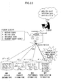
- a product number is managed by different MDRs by using "S/N:XYZ123", “PN:XYZ123”, “SERNO:XYZ123”, and “SN:XYZ123”, respectively.
- the FCMDB uses this common property as a key to integrate CIs managed by use of different local IDs. Namely, the FCMDB identifies CIs that are a "server” managed by the design information MDR, a "server” managed by the product information MDR, a "host” managed by the performance information MDR, and a "node” managed by the configuration information MDR, and integrates these CIs upon a client request to return it to the client.
- the FCMDB receives a request (i.e., query) from a client.
- the FCMDB collects identified CIs relating to the requested data from respective MDRs. These CIs are then integrated, and information about the integrated CI is transmitted to the client as a query result.
- a client requests data of resource A, resource B, and resource C.
- the FCMDB collects CIs A'', F3'', and C'' from the design information MDR, a CI B* from the product information MDR, CIs A ⁇ , B ⁇ , and C ⁇ from the performance information MDR, and CIs A', B', and C' from the configuration information MDR (it may be noted that A', A'', and A ⁇ have been identified in advance as resource A, and the same applies for resources B and C).
- Collected data may be all the data in the CIs, or may be partial data in the CIs.
- the FCMDB integrates the collected CIs into a query result, which is returned to the client.
- a particular MDR may have most data, resulting in access being concentrated on this MDR.
- the amount of data transfer increases for this MDR.
- An FCMDB may attempt to collect data simultaneously from MDRs, but cannot return a query result to the client until all the CIs are collected. It thus takes time in proportion to the amount of data returned from each MDR.
- the present invention is made to solve the above-noted problem, with the object to provide a configuration management system, proxy system, configuration management method that can distribute loads by providing a proxy (cache) between an FCMDB and MDRs.
- a configuration management system includes a plurality of databases that store information about resources as configuration items, a configuration management apparatus, a plurality of proxy apparatuses, and a proxy management apparatus, wherein the proxy management apparatus receives configuration items from the plurality of databases, reconciles the receives configuration items, selects a destination proxy apparatus such that processing by the plurality of proxy apparatuses is distributed over the proxy apparatuses, and sends the reconciled configuration items to the selected proxy apparatus, wherein the proxy apparatuses store configuration items sent from the proxy management apparatus, and wherein the configuration management apparatus receives a query from a client, selects among the plurality of proxy apparatuses a proxy apparatus that stores a configuration item that is to serve as a query result, and receives the configuration item from the selected proxy apparatus.
- a proxy system includes a plurality of proxy apparatuses, and a proxy management apparatus, wherein the proxy management apparatus receives configuration items from a plurality of databases that store information about resources as configuration items, reconciles the receives configuration items, selects a destination proxy apparatus such that processing by the plurality of proxy apparatuses is distributed over the proxy apparatuses, and sends the reconciled configuration items to the selected proxy apparatus, wherein the proxy apparatuses store configuration items sent from the proxy management apparatus, and send the configuration management apparatus one or more configuration items responsive to a request from the configuration management apparatus that receives a query from a client.
- a configuration management method includes a configuration item receiving step of receiving configuration items from a plurality of databases that store information about resources as configuration items, a reconcile step of reconciling the received configuration items, a destination proxy selecting step of selecting a destination proxy apparatus such that processing by the plurality of proxy apparatuses is distributed over the proxy apparatuses, a configuration item sending step of sending the reconciled configuration items to the selected proxy apparatus, a configuration item storing step of storing in the selected proxy apparatus the configuration items that are sent, and a configuration item receiving step of receiving a query from a client, selecting among the plurality of proxy apparatuses a proxy apparatus that stores a configuration item that is to serve as a query result, and receiving the configuration item from the selected proxy apparatus.
- Fig. 1 is a drawing for illustrating the overview of the first embodiment.
- a proxy system is situated between an FCMDB and MDRs.
- the proxy system includes a plurality of proxy apparatuses that store reconciled and integrated real data.
- the proxy apparatuses store configuration items (CIs) in a distributed manner, such that data integration has been performed for each CI.
- the MDRs have the same configuration as in the related art.
- a configuration management system 700 of the first embodiment includes an FCMDB (configuration management apparatus) 501, a proxy system 1, and a plurality of MDRs (i.e., MDR 201, MDR 202, MDR 203) (databases).
- FCMDB configuration management apparatus
- proxy system 1 proxy system 1
- MDRs MDRs 201, MDR 202, MDR 203
- the MDRs 201, 202, and 203 are databases that store information about resources as configuration items.
- Each of the MDRs 201, 202, and 203 includes a data acquisition service function unit 21 and a data management unit 23.
- the data acquisition service function unit 21 acquires data about IT resources from an external system.
- the data management unit 23 is a database function of the MDRs 201, 202, and 203, and stores data acquired by the data acquisition service function unit 21. Further, the data management unit 23 transmits the stored data as CIs to a proxy management apparatus 300 in the proxy system 1.
- the proxy system 1 includes two proxy apparatuses 101 and 102 and the proxy management apparatus 300 for managing these proxy apparatuses.
- the proxy apparatuses 101 and 102 have substantially the same configuration with each other.
- a proxy apparatus is denoted as "PROXY”
- the proxy management apparatus is denoted as "PROXY MANAGER”.
- the proxy management apparatus 300 acquires configuration items from the MDRs 201, 202, and 203, and reconcile the acquired configuration items. Further, the proxy management apparatus 300 selects a proxy apparatus as a transmission destination such that processing in the proxy apparatuses 101 and 102 is distributed over the proxy apparatuses, i.e., the numbers of configuration items stored in the proxy apparatuses 101 and 102 are substantially equal to each other. The proxy management apparatus 300 then transmits reconciled configuration items to the selected proxy apparatus.
- the proxy management apparatus 300 includes a data transfer unit 31, a data registration service function unit 32, and a data allocation information management unit 33.
- the data registration service function unit 32 receives CIs transmitted from the MDRs 201, 202, and 203.
- the data allocation information management unit 33 reconciles the CIs received by the data registration service function unit 32. Further, the data allocation information management unit 33 selects a proxy apparatus as a data allocation destination.
- the data transfer unit 31 transfers CIs to the selected proxy apparatus (i.e., the allocated proxy apparatus) .
- the proxy apparatuses 101 and 102 store the configuration items sent from the proxy management apparatus 300, and transmit CIs responsive to a request from the FCMDB 501 to the FCMDB 501.
- Each of the proxy apparatuses 101 and 102 includes a data acquisition service function unit 11, a data registration service function unit 12, and a data management unit 13.
- the data registration service function unit 12 receives CIs from the proxy management apparatus 300.
- the data management unit 13 is a database function for storing the CIs received by the data registration service function unit 12.
- the data management unit 13 returns requested CIs to the proxy management apparatus 300 based on a data request from the proxy management apparatus 300 that is received by the data acquisition service function unit 11.
- the data acquisition service function unit 11 receives a data request from the FCMDB 501.
- the FCMDB 501 receives a query from a client 600.
- the FCMDB 501 identifies, among the proxy apparatuses 101 and 102, the proxy apparatus that stores one or more configuration items that are to serve as a query result.
- the FCMDB 501 receives CIs from the identified proxy apparatus, and transmits the received CIs to the client 600 as a query result.
- the FCMDB 501 includes a data acquisition service function unit 51, a data registration service function unit 52, a data management unit 53, and a data mapping information management unit 54.
- the data acquisition service function unit 51 receives a query from the client 600.
- the data acquisition service function unit 51 also returns a query result to the client 600.
- the data registration service function unit 52 receives part of the CIs from the proxy system 1 at the time of data registration.
- the data management unit 53 is a database function of the FCMDB 501, and stores in a database the part of the CIs received by the data registration service function unit 52.
- the data mapping information management unit 54 stores, in a memory unit, allocation information regarding the CIs and the proxy apparatuses 101 and 102 of the proxy system 1.
- the configuration management system 700 serves to manage system configuration information about a management-target IT system 601.
- the MDRs 201, 202, and 203, the proxy apparatuses 101 and 102, the proxy management apparatus 300, and the FCMDB 501 in the configuration management system 700 are connected to each other through an operation-management-system network 800 to conduct data communication with each other.
- the MDRs 201, 202, and 203, the proxy apparatuses 101 and 102, the proxy management apparatus 300, and the FCMDB 501 are servers (i.e., computers) that include a CPU (Central Processing Unit), volatile and nonvolatile memory devices, and a communication interface.
- the function blocks illustrated in Fig. 2 are implemented through the collaboration of programs stored in the memory devices with hardware resources such as the CPU, memory devices, and communication interface.
- Fig. 4 Various types of data stored and used in the configuration management system 700 are illustrated in Fig. 4 through Fig. 7 .
- the MDRs 201, 202, and 203 store various types of data as illustrated in Fig. 4 and Fig. 5 in a DB.
- the MDR 201 stores resource design information separately for each resource in the management-target IT system 601.
- the MDR 201 stores each resource (server) ID as a CI type, and further stores properties inclusive of an IP address, a resource name, and a model number as well as values thereof on a CI-type-specific basis.
- CI types such as sv1, sv2, and so on are local IDs that are valid only within the MDR 201.
- the MDR 202 stores resource performance information separately for each resource in the management-target IT system 601.
- the MDR 202 stores each resource (server) ID as a CI type, and further stores properties inclusive of an IP address, a load average, and an average CPU utilization as well as values thereof on a CI-type-specific basis.
- CI types such as mdr2_id1, mdr2_id2, and so on are local IDs that are valid only within the MDR 202.
- the MDR 203 stores resource configuration information separately for each resource in the management-target IT system 601.
- the MDR 203 stores each resource (server) ID (server1, server2, switch1, etc.) as a CI type.
- server resource
- the MDR 203 further stores properties inclusive of an IP address, an apparatus name, a CPU clock frequency, a disk volume, and a status as well as values thereof.
- the MDR 203 further stores properties inclusive of an IP address, an apparatus name, a model number, a port quantity, and a status as well as values thereof.
- the MDR 203 stores properties inclusive of an IP address, an apparatus name, a disk volume, a disk utilization, and a status as well as values thereof. It may be noted that CI types such as sever1, server2, switch1, and so on are local IDs that are valid only within the MDR 203.
- a common property is the IP address.
- the IP address is used as a common property.
- Fig. 6 is a drawing illustrating data stored in the proxy management apparatus 300 and the FCMDB 501.
- Fig. 6-(A) illustrates various types of data managed by the data allocation information management unit 33 of the proxy management apparatus 300.
- the data allocation information management unit 33 stores an allocated destination proxy, a common property type, and a common property value for each CI type, thereby allocating a given CI type to a proxy apparatus.
- the data management unit 53 of the FCMDB 501 stores a CI type (global ID), a common property type, and a value thereof such that they are associated with each other (see Fig. 6-(B) ).
- the data mapping information management unit 54 of the FCMDB 501 stores a CI type (global ID) and a correspondence relationship between a proxy apparatus and a local ID for management within the proxy apparatus (see Fig. 6-(C) ).
- Fig. 7-(A) illustrates data stored in the proxy apparatus 101
- Fig. 7-(B) illustrates data stored in the proxy apparatus 102.
- the data management unit 13 stores property types and property values for each CI type such as lid0001, lid0002, svr1, and so on.
- the property types and property values are obtained by integrating data in the MDRs 201, 202, and 203.
- lid0001, lid0002, and so on are local IDs that are valid only within a proxy apparatus.
- Fig. 8 is a drawing illustrating electronic message data exchanged between the MDR 201, the proxy management apparatus 300, the proxy apparatus 101, and the FCMDB 501. As illustrated in Fig. 8 , exchanged electronic messages are provided in a format in which predefined tags are attached.
- Fig. 8-(A) illustrates an example of an electronic message format that is exchanged between the MDR 201 and the proxy management apparatus 300 and between the proxy management apparatus 300 and the proxy apparatus 101 at the time of new data registration.
- the MDR 201 Upon data being registered in the MDR 201, the MDR 201 sends the local ID used in the MDR 201 and the values of various types of properties including at least the common property to the proxy management apparatus 300 together with predetermined tags attached thereto.
- the proxy management apparatus 300 identifies an allocated destination proxy apparatus based on the common property (i.e., IP address in the first embodiment) contained in the received electronic message and the correspondence relationship stored in the data allocation information management unit 33.
- the proxy management apparatus 300 sends the received electronic message as it is to the identified proxy apparatus (i.e., proxy apparatus 101 in this example).
- the proxy apparatus 101 Upon receiving the electronic message, the proxy apparatus 101 sends the FCMDB 501 an electronic message in which predetermined tags are attached to the common property value and a local ID used in the proxy apparatus 101, i.e., the electronic message as illustrated in Fig. 8-(B) .
- the proxy apparatus 101 creates an electronic message for transmission to the FCMDB 501 by assigning a new local ID, and sends it to the FCMDB 501.
- the common property included in the transmitted electronic message may already be registered in the data management unit 13 (i.e., not new registration). In such a case, an electronic message for transmission to the FCMDB 501 is create by attaching the relevant local ID and transmitted to the FCMDB 501. Alternatively, no transmission may be performed in the absence of new registration since registration has already been made in the FCMDB 501.
- the FCMDB 501 Upon receiving the electronic message, the FCMDB 501 generates a global ID, and creates a correspondence between the generated global ID, the local ID included in the electronic message, and the sender proxy apparatus (i.e., proxy apparatus 101 in this example) for storage in the data mapping information management unit 54 (see Fig. 6-(C) ).
- the FCMDB 501 also causes the data management unit 53 to store the correspondence between the global ID and the common property value (see Fig. 6-(B) also).
- Fig. 8-(C) illustrates an example of an electronic message format that is transmitted from the proxy apparatus 101 to the FCMDB 501 as a query result upon a query request being issued from the client 600.
- the proxy apparatus 101 sends the properties and property values stored in the data management unit 13 to the FCMDB 501 as a query result by attaching predetermined tags.
- Fig. 8 has been explained with reference to electronic message data that is exchanged between the MDR 201, the proxy management apparatus 300, the proxy apparatus 101, and the FCMDB 501. The same or similar explanation also applies in the case of the MDR 202 or 203 and the proxy apparatus 102.
- Fig. 9 and Fig. 10 are flowcharts illustrating an operation performed by the configuration management system 700 when new resource registration is performed.
- a description will be given of the operation of the configuration management system 700 by referring to Fig. 9 and Fig. 10 .
- a function unit of an apparatus that is specified in parentheses performs a noted step.
- the passage "(data registration service function unit)" for S4 means that the data registration service function unit 32 of the proxy management apparatus 300 performs S4
- the passage "(data registration service function unit)" for S8 means that the data registration service function unit 12 of the proxy apparatus 101 (or proxy apparatus 102) performs S8.
- an apparatus is referred to as an agent that performs an action for the sake of convenience of explanation. An actual action, however, is performed by the function unit specified in parentheses in the figures upon exerting the function thereof.
- the MDR 201 receives data of the resources constituting the management-target IT system 601 from a user or an external system (S1). Further, the MDR 201 stores the received data by use of the configuration as illustrated in Fig. 4-(A) (S2), and transmits CIs (i.e., CI types, property types, and property values) to the proxy management apparatus 300 (S3).
- CIs i.e., CI types, property types, and property values
- the proxy management apparatus 300 receives the CIs from the MDR 201 (54), and reconcile the CIs (S5). After this, the proxy management apparatus 300 selects proxy apparatuses as data allocated destinations based on the table stored in the data allocation information management unit 33 (S6). When the common property is new, the proxy management apparatus 300 selects proxy apparatuses in a round-robin manner such that data are evenly allocated, i.e., CI quantities become even, followed by registering the correspondence relationships in a table.
- the proxy management apparatus 300 transmits CI data (S7) to a selected proxy apparatus (e.g., proxy apparatus 101) that is selected in S6.
- a selected proxy apparatus e.g., proxy apparatus 101
- the proxy apparatus 101 receives the CI data (S8), and stores the data (S9).
- the data is integrated in S9.
- the storage format used here is the same as the one illustrated in Fig. 7-(A) .
- the proxy apparatus 101 transmits part of the CI data (i.e., local ID and common property) to the FCMDB 501 (S10).
- the FCMDB 501 receives the part of the CI data (S11), and stores the received data as illustrated in Fig. 6-(B) (S12), followed by storing allocation information regarding CIs and the proxy apparatus as illustrated in Fig. 6-(C) .
- the FCMDB 501 receives a query issued by the client 600 (S21).
- the FCMDB 501 retrieves relevant data from the data management unit 53 (S22) when a result for the query is stored in the local database (some properties of the CIs are stored in the FCMDB 501 in the first embodiment). If all the data to be transmitted as a query result are obtained (Yes in S23), the FCMDB 501 returns the query result to the client 600 (S24). With this, the procedure comes to an end.
- the FCMDB 501 selects a proxy apparatus that has missing data based on the table stored in the data mapping information management unit 54 (S25), followed by requesting the selected proxy apparatus (e. g. , proxy apparatus 101 may be selected) to provide the missing data (S26).
- the proxy apparatus 101 receives the data request (S27), and returns the data stored in the data management unit 13 to the FCMDB 501 (S28).
- the FCMDB 501 receives the returned data (S22), and checks again whether all the data are obtained (S23). If all the data are obtained (Yes in S23), the query result is returned to the client 600 (S24) . With this, the procedure comes to an end. If all the data are not yet obtained (No in S23), the processes of S25 through S28 are performed with respect to other proxy apparatuses.
- the provision of plural proxy apparatuses that store reconciled, integrated data in a distributed manner on a CI-specific basis between an FCMDB and MDRs can distributed data in the proxy layer.
- the same number of CIs are allocated to each of the proxy apparatuses through round robin.
- the proxy apparatus having these CIs allocated thereto may receive excessive accesses, resulting in lower performance.
- the second embodiment provides a configuration management system that can distribute loads even when queries directed to particular CIs are frequently issued.
- Fig. 12 is a drawing illustrating an example of the outline of the second embodiment.
- the proxy system of the second embodiment reallocates CIs other than A and B from the excessively accessed proxy apparatus to other proxy apparatuses. With this arrangement, processing loads Of the proxy apparatuses can be distributed.
- FIG. 13 is a block diagram illustrating a configuration management system of the second embodiment.
- a proxy system 2 of a configuration management system 701 includes proxy apparatuses 111 and 112 and a proxy management apparatus 310.
- the proxy management apparatus 310 includes a load distribution management unit 34.
- Each of the proxy apparatuses 111 and 112 includes a load information management unit 14.
- the load distribution management unit 34 of then proxy management apparatus 310 transmits a collection request to the load information management unit 14 of each proxy apparatus to collect load information (e.g., the data amount of each stored CI, the data transfer amount of each CI, CPU utilization, access load, etc.).
- the load distribution management unit 34 of the proxy management apparatus 310 receives load information collected by the load information management unit 14 of each proxy apparatus, and adjusts CI data distribution based on the load information about each proxy apparatus, followed by instructing each proxy apparatus to move CI data.
- the load information management unit 14 of each proxy apparatus receives the collection request from the load distribution management unit 34 of the proxy management apparatus 310, and collects local load information, followed by transmitting the collected load information to the load distribution management unit 34.
- the function units of the proxy apparatuses 111 and 112 and the FCMDB 501 in the second embodiment perform additional processes for reallocating CIs.
- the additional processes will be described with reference the following flowcharts.
- the proxy management apparatus 310 requests (531) the proxy apparatuses 111 and 112 to collect load information in response to an instruction from the client 600 or at a specified time or at intervals specified by a user in advance such as constant intervals or the time at which the configuration management system 701 is not used by the user.
- Each of the proxy apparatuses 111 and 112 collects local load information in response to the load information collection request (S32, S33), followed by sending the load information, to the proxy management apparatus 310 (334, 335).
- the proxy management apparatus 310 adjusts data allocation based on the load information about the proxy apparatuses (S36).
- the load information may indicate the data transfer amount of each CI.
- the proxy management apparatus 310 divides the total amount of data transfer by the number of proxy apparatuses to calculate an average of data transfer amounts.
- the proxy management apparatus 310 then adjusts CI allocation such that the data transfer amounts in the proxy apparatuses become close to the average.
- the proxy management apparatus 310 takes into account differences in machine specifications between the proxy apparatuses if such differences exist. For example, CPU specifications may differ from proxy apparatus to proxy apparatus. In such a case, the proxy management apparatus 310 may adjust the total data transfer amount based on the CPU specifications (e.g., frequency).
- the CPU specifications e.g., frequency
- the proxy management apparatus 310 instructs the proxy apparatus 111 and the proxy apparatus 112 to move CIs (S37). It may be noted that the electronic instruction message sent to the proxy apparatuses 111 and 112 may include information about which CIs are to be moved. In the following, a description will be given of an example in which CIs are moved from the proxy apparatus 111 to the proxy apparatus 112.
- the proxy apparatus 111 transmits (S38) to the proxy apparatus 112 the CIs that are indicated as CIs to be moved by the move instruction from the proxy management apparatus 310. After this, the proxy apparatus 111 deletes the stored CIs that have been transmitted (S39). In response to instruction from the proxy apparatus 111, for example, the FCMDB 501 unregisters the allocation of the CIs to the proxy apparatus (S10).
- the proxy apparatus 112 receives the CIs sent from the proxy apparatus 111 (S41), and stores the received CIs as its own CIs (S42). After this, the proxy apparatus 112 attaches local IDs to the stored CIs according to need, and sends part of the CIs (i.e., common property and local ID) to the FCMDB 501 (S43).
- the FCMDB 501 receives the part of the CIs sent from the proxy apparatus 112 (S44), and stores the received part of the CIs (S45). Thereafter, the FCMDB 501 stores information about the allocation of the moved CIs to the proxy apparatus 112 (S46).
- the load distribution function is provided to redistribute data in response to load statuses when an uneven access pattern is observed.
- the configuration management system 701 can provide data to the user even faster.
- an FCMDB alone or each MDR manages backup version numbers. This gives rise to a problem in that loads are concentrated on the FCMDB or a particular MDR.
- the configuration management system of the third embodiment can perform version number management within the proxy system, thereby evenly distributing loads.
- Fig. 16 is a drawing illustrating an example of the outline of third embodiment.
- the current version i.e., version number
- version n is denoted as "vn” in Fig. 16
- An immediately preceding version 8 is obtained by merging version 4 and version 7.
- apparatuses, in the proxy system do not perform backup at respective, different timings, but perform backup simultaneously so as to distribute loads and to prevent data inconsistency caused by differences between versions.
- FIG. 17 is a block diagram illustrating a configuration management system of the third embodiment.
- a configuration management system 702 includes a FCMDB 521 and a proxy system 3.
- the FCMDB 521 includes a version number management unit 55.
- the version number management unit 55 issues a request to start version-number processing to each function unit of the FCMDB 521 and to the proxy system 3.
- the version number management unit 55 notifies the client 600 of an end of processing when the version-number processing comes to an end.
- the proxy system 3 of the configuration management system 702 includes proxy apparatuses 121 and 122 and a proxy management apparatus 320.
- the proxy management apparatus 320 includes a version number management unit 35, which receives version-number data (data indicative of an adopted number) from the FCMDB 521, and causes the data allocation information, management unit 33 of the proxy management apparatus 320 to store a differential between the current data and the data of a preceding version number.
- Each of the proxy apparatuses 121 and 122 includes a version number management unit 15, which receives version-number data from the FCMDB 521, and causes the data management unit 13 of the proxy apparatuses 121 and 122 to store a differential between the current data and the data of a preceding version, number.
- the function units of the proxy apparatuses 121 and 122, the proxy management apparatus 320, and the FCMDB 521 in the third embodiment perform additional processes for performing version-number management.
- the additional processes will be described with reference the following flowcharts.
- the FCMDB 521 Upon receiving an instruction to start version-number processing from the client 600, for example, the FCMDB 521 sends a notice indicative of the start of version-number processing to the proxy apparatuses 121 and 122 and the proxy management apparatus 320 (S51). Furthers, the FCMDB 521 stops receiving a request from the client 600 (S52).
- the proxy management apparatus 320 Upon receiving the notices the proxy management apparatus 320 stops receiving a request from the MDRs, and sends a notice of stoppage completion to the FCMDB 521 (S54). Further, the proxy apparatuses 121 and 122 stop receiving a request from the proxy management apparatus 320, and sends a notice of stoppage completion to the FCMDB 521 (S53).
- the FCMDB 521 Upon receiving the notice of stoppage completion, the FCMDB 521 adopts a version number (S55). The FCMDB 521 then notifies the proxy apparatuses 121 and 122 and the proxy management apparatus 320 of the adopted version-number data thereby to request version-number updating (S56). After this, the FCMDB 521 stores (S57) differential data (which refers to, and will hereinafter refer to, differential data between the current data and the immediately preceding version-number data) of data mapping information (i.e., data illustrated in Fig. 6-(C) ). Further, the FCMDB 521 stores (S58) differential data of the management data (i.e., data illustrated in Fig. 6-(B) ).
- the proxy management apparatus 320 receivers the version-number data (S61).
- the proxy management apparatus 320 stores differential data of the data allocation information (i.e., data illustrated in Fig. 6-(A) ), followed by sending a notice of completion to the FCMDB 521 upon completing the storing (S62).
- the proxy apparatuses 121 and 122 receive the version-number data (S59).
- the proxy apparatuses 121 and 122 store differential data of the management data (i.e., data illustrated in Fig. 7 ), followed by sending a notice of completion to the FCMDB 521 upon completing the storing (S60).
- the data stored by the processes performed in S57, S53, S60, and S62 are provided with the version number adopted in step S55.
- the FCMDB 521 After the completion of the processes of S57, S58, S60, and S62, the FCMDB 521 notifies the proxy apparatuses 121 and 122 and the proxy management, apparatus 320 of the completion of version-number processing (S63). Thereafter the FCMDB 521 starts receiving a request from the client 600 (S64).
- the proxy apparatuses 121 and 122 Upon being notified of the completion of version-number processing, the proxy apparatuses 121 and 122 resume receiving a request from the proxy management apparatus 320 (S65). Further, the proxy management apparatus 320 resumes receiving a request from the MDR (S66).
- the configuration management systems of the above-described embodiments may provide the following advantages.
- the configuration management systems of the above-described embodiments may be provided with a proxy system that makes use of FCMDB features, thereby evenly distributing data.
- the configuration management systems of the above-described embodiment may distribute accesses.
- the configuration management systems of the above-described embodiments may consolidate (i.e., reconcile and integrate) the same CI data in advance, thereby making data acquisition more efficient.
- the proxy system may be provided with a dynamic load distribution function, thereby dynamically redistributing data between proxy apparatuses in response to usage conditions.
- the version-number processing is evenly spread because the data are evenly distributed, thereby increasing the speed of version-number-updating processing as a whole.
- a proxy system serving as a proxy layer is provided in a configuration management system to evenly distribute date, thereby distributing loads to increase processing speed.
Abstract
Description
- The present invention relates to a configuration management system, proxy system, and configuration management method that manage resource configurations.
- An FCMDB (federated configuration management database) has been developed to virtually integrate data in different types of DBs (databases). The FCMDB is a DB that can operate plural MDRs (management data depositories) in a cross-sectional manner. An MDR corresponds to an operation management middleware DB that has IT-system operation management data (real data). It may be noted that the type and quantity of data vary from MDR to MDR.
-
Fig. 20 is a drawing illustrating the outline of a configuration of a configuration management system. An FCMDB integrates data in the MDR for managing design information real data, data in the MDR for managing product information real data, data in the MDR for managing performance information real data, and data in the MDR for managing configuration information real data (e.g., information C'', C^, C' may be integrated into C). - An FCMDB integrates data in different MDRs by use of the following functions. Namely, the FCMDB converts, into a common format (i.e., conversion into common format), information about configuration items (hereinafter referred to as "CI": e.g., data about resources constituting an IT system such as a server, a storage, software, and the like) managed on an MDR-specific basis by use of different names and structures. Further, the FCMDB uses a common property having a unique value as a key to identify (i.e., reconcile) a CI that is managed by use of different local IDs in different MDs. Moreover, the FCMDB integrates information items belonging to the same CI (i.e., data integration). It may be noted that the FCMDB actually integrates data when returning data to a client. Further, the FCMDB also manages relationships between CIs ("manage" is a collective term for storing, updating, deleting, and registering).
- In an example illustrated in
Fig. 21 , a product number is managed by different MDRs by using "S/N:XYZ123", "PN:XYZ123", "SERNO:XYZ123", and "SN:XYZ123", respectively. The FCMDB uses this common property as a key to integrate CIs managed by use of different local IDs. Namely, the FCMDB identifies CIs that are a "server" managed by the design information MDR, a "server" managed by the product information MDR, a "host" managed by the performance information MDR, and a "node" managed by the configuration information MDR, and integrates these CIs upon a client request to return it to the client. - A description of the operation of the FCMDB performed upon a client request will be given by referring to
Fig. 22 . - The FCMDB receives a request (i.e., query) from a client. The FCMDB collects identified CIs relating to the requested data from respective MDRs. These CIs are then integrated, and information about the integrated CI is transmitted to the client as a query result. In an example illustrated in
Fig. 22 , a client requests data of resource A, resource B, and resource C. In response, the FCMDB collects CIs A'', F3'', and C'' from the design information MDR, a CI B* from the product information MDR, CIs A^, B^, and C^ from the performance information MDR, and CIs A', B', and C' from the configuration information MDR (it may be noted that A', A'', and A^ have been identified in advance as resource A, and the same applies for resources B and C). Collected data may be all the data in the CIs, or may be partial data in the CIs. - The FCMDB integrates the collected CIs into a query result, which is returned to the client.
- The following document is known as a related-art document.
- [Patent Document 1] Japanese Laid-open Patent Publication No.
2001-51890 - The related problem is illustrated in
Fig. 23 , and will be described bellow. As illustrated inFig. 23 , a particular MDR may have most data, resulting in access being concentrated on this MDR. The amount of data transfer increases for this MDR. In this manner, an MDR having most data ends up being a bottleneck. An FCMDB may attempt to collect data simultaneously from MDRs, but cannot return a query result to the client until all the CIs are collected. It thus takes time in proportion to the amount of data returned from each MDR. - This problem does not arise if the arrangement is made such that all the data are cached in the FCMDB. However, such an arrangement is not suitable for the management of data in a large-scale system because the data amount becomes excessively large.
- The present invention is made to solve the above-noted problem, with the object to provide a configuration management system, proxy system, configuration management method that can distribute loads by providing a proxy (cache) between an FCMDB and MDRs.
- A configuration management system includes a plurality of databases that store information about resources as configuration items, a configuration management apparatus, a plurality of proxy apparatuses, and a proxy management apparatus, wherein the proxy management apparatus receives configuration items from the plurality of databases, reconciles the receives configuration items, selects a destination proxy apparatus such that processing by the plurality of proxy apparatuses is distributed over the proxy apparatuses, and sends the reconciled configuration items to the selected proxy apparatus, wherein the proxy apparatuses store configuration items sent from the proxy management apparatus, and wherein the configuration management apparatus receives a query from a client, selects among the plurality of proxy apparatuses a proxy apparatus that stores a configuration item that is to serve as a query result, and receives the configuration item from the selected proxy apparatus.
- A proxy system includes a plurality of proxy apparatuses, and a proxy management apparatus, wherein the proxy management apparatus receives configuration items from a plurality of databases that store information about resources as configuration items, reconciles the receives configuration items, selects a destination proxy apparatus such that processing by the plurality of proxy apparatuses is distributed over the proxy apparatuses, and sends the reconciled configuration items to the selected proxy apparatus, wherein the proxy apparatuses store configuration items sent from the proxy management apparatus, and send the configuration management apparatus one or more configuration items responsive to a request from the configuration management apparatus that receives a query from a client.
- A configuration management method includes a configuration item receiving step of receiving configuration items from a plurality of databases that store information about resources as configuration items, a reconcile step of reconciling the received configuration items, a destination proxy selecting step of selecting a destination proxy apparatus such that processing by the plurality of proxy apparatuses is distributed over the proxy apparatuses, a configuration item sending step of sending the reconciled configuration items to the selected proxy apparatus, a configuration item storing step of storing in the selected proxy apparatus the configuration items that are sent, and a configuration item receiving step of receiving a query from a client, selecting among the plurality of proxy apparatuses a proxy apparatus that stores a configuration item that is to serve as a query result, and receiving the configuration item from the selected proxy apparatus.
-
-
Fig. 1 is a drawing for illustrating the overview of a first embodiment. -
Fig. 2 is a drawing illustrating an example of the functional configuration of a configuration management system according to the first embodiment. -
Fig. 3 is a drawing illustrating an example of the physical configuration of the configuration management system according to the first embodiment. -
Fig. 4 is a drawing illustrating an example of data stored in MDRs according to the first embodiment. -
Fig. 5 is a drawing illustrating an example of data stored in MDRs according to the first embodiment. -
Fig. 6 is a drawing illustrating an example of data stored in a proxy management apparatus and an FCMDB according to the first embodiment. -
Fig. 7 is a drawing illustrating an example of data stored in a data management unit of a proxy apparatus according to the first embodiment. -
Fig. 8 is a drawing illustrating an example of electronic message data exchanged between the MDRs, the proxy management apparatus, the proxy apparatuses, and the FCMDB according to the first embodiment. -
Fig. 9 is a flowchart illustrating an operation performed by the configuration management system when new resource registration is performed according to the first embodiment. -
Fig. 10 is a flowchart illustrating an operation performed by the configuration management system when new resource registration is performed according to the first embodiment. -
Fig. 11 is a flowchart illustrating an operation performed when a client issues a query according to the first embodiment. -
Fig. 12 is a drawing for illustrating the overview of a second embodiment. -
Fig. 13 is a drawing illustrating an example of the functional configuration of a configuration management system according to the second embodiment. -
Fig. 14 is a drawing illustrating an example of an operation performed by the configuration management system according to the second embodiment. -
Fig. 15 is a drawing illustrating an example of an operation performed by the configuration management system according to the second embodiment. -
Fig. 16 is a drawing for illustrating the overview of a third embodiment. -
Fig. 17 is a drawing illustrating an example of the functional configuration of a configuration management system according to the third embodiment. -
Fig. 18 is a drawing illustrating an example of an operation performed by the configuration management system according to the third embodiment. -
Fig. 19 is a drawing illustrating an example of an operation performed by the configuration management system according to the third embodiment. -
Fig. 20 is a drawing illustrating an outline of the configuration of a related-part configuration management system. -
Fig. 21 is a drawing for illustrating the reconcile and integrate processes of the configuration management system. -
Fig. 22 is a drawing illustrating an operation performed by the configuration management system upon a request from a client. -
Fig. 23 is a drawing illustrating a problem of the related-art configuration management system. - In the following, a first embodiment will be described with reference to drawings.
Fig. 1 is a drawing for illustrating the overview of the first embodiment. - In the first embodiment, a proxy system is situated between an FCMDB and MDRs. The proxy system includes a plurality of proxy apparatuses that store reconciled and integrated real data. The proxy apparatuses store configuration items (CIs) in a distributed manner, such that data integration has been performed for each CI. The MDRs have the same configuration as in the related art.
- In the following, a description will be given of an example of the functional configuration of a configuration management system according to the first embodiment by referring to
Fig. 2 . - A
configuration management system 700 of the first embodiment includes an FCMDB (configuration management apparatus) 501, aproxy system 1, and a plurality of MDRs (i.e.,MDR 201,MDR 202, MDR 203) (databases). - The
MDRs MDRs service function unit 21 and adata management unit 23. The data acquisitionservice function unit 21 acquires data about IT resources from an external system. Thedata management unit 23 is a database function of theMDRs service function unit 21. further, thedata management unit 23 transmits the stored data as CIs to aproxy management apparatus 300 in theproxy system 1. - If the following, a description will be given of the interval configuration of the
proxy system 1. Theproxy system 1 includes twoproxy apparatuses proxy management apparatus 300 for managing these proxy apparatuses. Theproxy apparatuses Fig. 1 and subsequent drawings, a proxy apparatus is denoted as "PROXY", and the proxy management apparatus is denoted as "PROXY MANAGER". - The
proxy management apparatus 300 acquires configuration items from theMDRs proxy management apparatus 300 selects a proxy apparatus as a transmission destination such that processing in theproxy apparatuses proxy apparatuses proxy management apparatus 300 then transmits reconciled configuration items to the selected proxy apparatus. - The
proxy management apparatus 300 includes adata transfer unit 31, a data registrationservice function unit 32, and a data allocationinformation management unit 33. The data registrationservice function unit 32 receives CIs transmitted from theMDRs information management unit 33 reconciles the CIs received by the data registrationservice function unit 32. Further, the data allocationinformation management unit 33 selects a proxy apparatus as a data allocation destination. Thedata transfer unit 31 transfers CIs to the selected proxy apparatus (i.e., the allocated proxy apparatus) . - The
proxy apparatuses proxy management apparatus 300, and transmit CIs responsive to a request from theFCMDB 501 to theFCMDB 501. - Each of the
proxy apparatuses service function unit 11, a data registrationservice function unit 12, and adata management unit 13. The data registrationservice function unit 12 receives CIs from theproxy management apparatus 300. Thedata management unit 13 is a database function for storing the CIs received by the data registrationservice function unit 12. Thedata management unit 13 returns requested CIs to theproxy management apparatus 300 based on a data request from theproxy management apparatus 300 that is received by the data acquisitionservice function unit 11. The data acquisitionservice function unit 11 receives a data request from theFCMDB 501. - The
FCMDB 501 receives a query from aclient 600. TheFCMDB 501 identifies, among theproxy apparatuses FCMDB 501 receives CIs from the identified proxy apparatus, and transmits the received CIs to theclient 600 as a query result. - The
FCMDB 501 includes a data acquisitionservice function unit 51, a data registrationservice function unit 52, adata management unit 53, and a data mappinginformation management unit 54. - The data acquisition
service function unit 51 receives a query from theclient 600. The data acquisitionservice function unit 51 also returns a query result to theclient 600. The data registrationservice function unit 52 receives part of the CIs from theproxy system 1 at the time of data registration. Thedata management unit 53 is a database function of theFCMDB 501, and stores in a database the part of the CIs received by the data registrationservice function unit 52. Further, the data mappinginformation management unit 54 stores, in a memory unit, allocation information regarding the CIs and theproxy apparatuses proxy system 1. - In the following, a physical configuration of the
configuration management system 700 will be described by referring toFig. 3 . Theconfiguration management system 700 serves to manage system configuration information about a management-target IT system 601. TheMDRs proxy apparatuses proxy management apparatus 300, and theFCMDB 501 in theconfiguration management system 700 are connected to each other through an operation-management-system network 800 to conduct data communication with each other. TheMDRs proxy apparatuses proxy management apparatus 300, and theFCMDB 501 are servers (i.e., computers) that include a CPU (Central Processing Unit), volatile and nonvolatile memory devices, and a communication interface. The function blocks illustrated inFig. 2 are implemented through the collaboration of programs stored in the memory devices with hardware resources such as the CPU, memory devices, and communication interface. - Various types of data stored and used in the
configuration management system 700 are illustrated inFig. 4 through Fig. 7 . - A description will be first given of various types of data stored in the
MDRs Fig. 4 andFig. 5 . TheMDRs Fig. 4 andFig. 5 in a DB. - As illustrated in
Fig. 4-(A) , theMDR 201 stores resource design information separately for each resource in the management-target IT system 601. In the first embodiment, theMDR 201 stores each resource (server) ID as a CI type, and further stores properties inclusive of an IP address, a resource name, and a model number as well as values thereof on a CI-type-specific basis. It may be noted that CI types such as sv1, sv2, and so on are local IDs that are valid only within theMDR 201. - As illustrated in
Fig. 4-(B) , theMDR 202 stores resource performance information separately for each resource in the management-target IT system 601. In the first embodiment, theMDR 202 stores each resource (server) ID as a CI type, and further stores properties inclusive of an IP address, a load average, and an average CPU utilization as well as values thereof on a CI-type-specific basis. It may be noted that CI types such as mdr2_id1, mdr2_id2, and so on are local IDs that are valid only within theMDR 202. - As illustrated in
Fig. 5 , theMDR 203 stores resource configuration information separately for each resource in the management-target IT system 601. In the first embodiment, theMDR 203 stores each resource (server) ID (server1, server2, switch1, etc.) as a CI type. In the case of a CI type indicative of a server, theMDR 203 further stores properties inclusive of an IP address, an apparatus name, a CPU clock frequency, a disk volume, and a status as well as values thereof. In the case of a CI type indicative of a switch, theMDR 203 further stores properties inclusive of an IP address, an apparatus name, a model number, a port quantity, and a status as well as values thereof. In the case of a CI type indicative of a storage, further, theMDR 203 stores properties inclusive of an IP address, an apparatus name, a disk volume, a disk utilization, and a status as well as values thereof. It may be noted that CI types such as sever1, server2, switch1, and so on are local IDs that are valid only within theMDR 203. - Among the CIs stored in the
MDRs -
Fig. 6 is a drawing illustrating data stored in theproxy management apparatus 300 and theFCMDB 501. -
Fig. 6-(A) illustrates various types of data managed by the data allocationinformation management unit 33 of theproxy management apparatus 300. The data allocationinformation management unit 33 stores an allocated destination proxy, a common property type, and a common property value for each CI type, thereby allocating a given CI type to a proxy apparatus. - The
data management unit 53 of theFCMDB 501 stores a CI type (global ID), a common property type, and a value thereof such that they are associated with each other (seeFig. 6-(B) ). The data mappinginformation management unit 54 of theFCMDB 501 stores a CI type (global ID) and a correspondence relationship between a proxy apparatus and a local ID for management within the proxy apparatus (seeFig. 6-(C) ). - In the following, a description will be given of data stored in the
data management unit 13 of theproxy apparatuses Fig. 7. Fig. 7-(A) illustrates data stored in theproxy apparatus 101, andFig. 7-(B) illustrates data stored in theproxy apparatus 102. - The
data management unit 13 stores property types and property values for each CI type such as lid0001, lid0002, svr1, and so on. The property types and property values are obtained by integrating data in theMDRs -
Fig. 8 is a drawing illustrating electronic message data exchanged between theMDR 201, theproxy management apparatus 300, theproxy apparatus 101, and theFCMDB 501. As illustrated inFig. 8 , exchanged electronic messages are provided in a format in which predefined tags are attached. -
Fig. 8-(A) illustrates an example of an electronic message format that is exchanged between theMDR 201 and theproxy management apparatus 300 and between theproxy management apparatus 300 and theproxy apparatus 101 at the time of new data registration. Upon data being registered in theMDR 201, theMDR 201 sends the local ID used in theMDR 201 and the values of various types of properties including at least the common property to theproxy management apparatus 300 together with predetermined tags attached thereto. Theproxy management apparatus 300 identifies an allocated destination proxy apparatus based on the common property (i.e., IP address in the first embodiment) contained in the received electronic message and the correspondence relationship stored in the data allocationinformation management unit 33. Theproxy management apparatus 300 sends the received electronic message as it is to the identified proxy apparatus (i.e.,proxy apparatus 101 in this example). - Upon receiving the electronic message, the
proxy apparatus 101 sends the FCMDB 501 an electronic message in which predetermined tags are attached to the common property value and a local ID used in theproxy apparatus 101, i.e., the electronic message as illustrated inFig. 8-(B) . At the time of new registration theproxy apparatus 101 creates an electronic message for transmission to theFCMDB 501 by assigning a new local ID, and sends it to theFCMDB 501. The common property included in the transmitted electronic message may already be registered in the data management unit 13 (i.e., not new registration). In such a case, an electronic message for transmission to theFCMDB 501 is create by attaching the relevant local ID and transmitted to theFCMDB 501. Alternatively, no transmission may be performed in the absence of new registration since registration has already been made in theFCMDB 501. - Upon receiving the electronic message, the
FCMDB 501 generates a global ID, and creates a correspondence between the generated global ID, the local ID included in the electronic message, and the sender proxy apparatus (i.e.,proxy apparatus 101 in this example) for storage in the data mapping information management unit 54 (seeFig. 6-(C) ). TheFCMDB 501 also causes thedata management unit 53 to store the correspondence between the global ID and the common property value (seeFig. 6-(B) also). -
Fig. 8-(C) illustrates an example of an electronic message format that is transmitted from theproxy apparatus 101 to theFCMDB 501 as a query result upon a query request being issued from theclient 600. When theclient 600 issues a query regarding the IP address "192.168.0-1" (or issues a query indicative of a global ID), theproxy apparatus 101 sends the properties and property values stored in thedata management unit 13 to theFCMDB 501 as a query result by attaching predetermined tags. - The example illustrated in
Fig. 8 has been explained with reference to electronic message data that is exchanged between theMDR 201, theproxy management apparatus 300, theproxy apparatus 101, and theFCMDB 501. The same or similar explanation also applies in the case of theMDR proxy apparatus 102. -
Fig. 9 andFig. 10 are flowcharts illustrating an operation performed by theconfiguration management system 700 when new resource registration is performed. A description will be given of the operation of theconfiguration management system 700 by referring toFig. 9 andFig. 10 . In the flowcharts hereinafter illustrated, a function unit of an apparatus that is specified in parentheses performs a noted step. Even when function units having the same name are used, the passage "(data registration service function unit)" for S4 means that the data registrationservice function unit 32 of theproxy management apparatus 300 performs S4 while the passage "(data registration service function unit)" for S8 means that the data registrationservice function unit 12 of the proxy apparatus 101 (or proxy apparatus 102) performs S8. Further, the following descriptions will be given such that an apparatus is referred to as an agent that performs an action for the sake of convenience of explanation. An actual action, however, is performed by the function unit specified in parentheses in the figures upon exerting the function thereof. - Moreover, the following descriptions based on the flowcharts will be given with reference to operations between the
FCMDB 501, theproxy apparatus 101, theproxy management apparatus 300, and theMDR 201. The same or similar operations are performed in the case of theproxy apparatus 102 and theMDR - The
MDR 201 receives data of the resources constituting the management-target IT system 601 from a user or an external system (S1). Further, theMDR 201 stores the received data by use of the configuration as illustrated inFig. 4-(A) (S2), and transmits CIs (i.e., CI types, property types, and property values) to the proxy management apparatus 300 (S3). - The
proxy management apparatus 300 receives the CIs from the MDR 201 (54), and reconcile the CIs (S5). After this, theproxy management apparatus 300 selects proxy apparatuses as data allocated destinations based on the table stored in the data allocation information management unit 33 (S6). When the common property is new, theproxy management apparatus 300 selects proxy apparatuses in a round-robin manner such that data are evenly allocated, i.e., CI quantities become even, followed by registering the correspondence relationships in a table. - The
proxy management apparatus 300 transmits CI data (S7) to a selected proxy apparatus (e.g., proxy apparatus 101) that is selected in S6. - The
proxy apparatus 101 receives the CI data (S8), and stores the data (S9). The data is integrated in S9. The storage format used here is the same as the one illustrated inFig. 7-(A) . Further, theproxy apparatus 101 transmits part of the CI data (i.e., local ID and common property) to the FCMDB 501 (S10). - The
FCMDB 501 receives the part of the CI data (S11), and stores the received data as illustrated inFig. 6-(B) (S12), followed by storing allocation information regarding CIs and the proxy apparatus as illustrated inFig. 6-(C) . - In the following, a description will be given of the operation performed when a query is issued from the
client 600 by referring to the flowchart ofFig. 11 . - The
FCMDB 501 receives a query issued by the client 600 (S21). TheFCMDB 501 retrieves relevant data from the data management unit 53 (S22) when a result for the query is stored in the local database (some properties of the CIs are stored in theFCMDB 501 in the first embodiment). If all the data to be transmitted as a query result are obtained (Yes in S23), theFCMDB 501 returns the query result to the client 600 (S24). With this, the procedure comes to an end. - If all the data are not yet obtained (No in S23), the
FCMDB 501 selects a proxy apparatus that has missing data based on the table stored in the data mapping information management unit 54 (S25), followed by requesting the selected proxy apparatus (e. g. ,proxy apparatus 101 may be selected) to provide the missing data (S26). - The
proxy apparatus 101 receives the data request (S27), and returns the data stored in thedata management unit 13 to the FCMDB 501 (S28). - The
FCMDB 501 receives the returned data (S22), and checks again whether all the data are obtained (S23). If all the data are obtained (Yes in S23), the query result is returned to the client 600 (S24) . With this, the procedure comes to an end. If all the data are not yet obtained (No in S23), the processes of S25 through S28 are performed with respect to other proxy apparatuses. - According to the first embodiment, the provision of plural proxy apparatuses that store reconciled, integrated data in a distributed manner on a CI-specific basis between an FCMDB and MDRs can distributed data in the proxy layer.
- In the first embodiment, the same number of CIs are allocated to each of the proxy apparatuses through round robin. When a query directed to one or more particular CIs are frequently issued, the proxy apparatus having these CIs allocated thereto may receive excessive accesses, resulting in lower performance. The second embodiment provides a configuration management system that can distribute loads even when queries directed to particular CIs are frequently issued.
-
Fig. 12 is a drawing illustrating an example of the outline of the second embodiment. When excessive accesses are directed to CIs that are A and B, the proxy system of the second embodiment reallocates CIs other than A and B from the excessively accessed proxy apparatus to other proxy apparatuses. With this arrangement, processing loads Of the proxy apparatuses can be distributed. -
Fig. 13 is a block diagram illustrating a configuration management system of the second embodiment. Aproxy system 2 of aconfiguration management system 701 includesproxy apparatuses proxy management apparatus 310. Theproxy management apparatus 310 includes a loaddistribution management unit 34. Each of theproxy apparatuses information management unit 14. - The load
distribution management unit 34 of thenproxy management apparatus 310 transmits a collection request to the loadinformation management unit 14 of each proxy apparatus to collect load information (e.g., the data amount of each stored CI, the data transfer amount of each CI, CPU utilization, access load, etc.). The loaddistribution management unit 34 of theproxy management apparatus 310 receives load information collected by the loadinformation management unit 14 of each proxy apparatus, and adjusts CI data distribution based on the load information about each proxy apparatus, followed by instructing each proxy apparatus to move CI data. - The load
information management unit 14 of each proxy apparatus receives the collection request from the loaddistribution management unit 34 of theproxy management apparatus 310, and collects local load information, followed by transmitting the collected load information to the loaddistribution management unit 34. - In addition to what is described above, the function units of the
proxy apparatuses FCMDB 501 in the second embodiment perform additional processes for reallocating CIs. The additional processes will be described with reference the following flowcharts. - A description will be given of the operations of the
configuration management system 701 according to the second embodiment by referring to the flowcharts ofFig. 14 andFig. 15 . - The
proxy management apparatus 310 requests (531) theproxy apparatuses client 600 or at a specified time or at intervals specified by a user in advance such as constant intervals or the time at which theconfiguration management system 701 is not used by the user. Each of theproxy apparatuses - The
proxy management apparatus 310 adjusts data allocation based on the load information about the proxy apparatuses (S36). The load information may indicate the data transfer amount of each CI. In this case, theproxy management apparatus 310 divides the total amount of data transfer by the number of proxy apparatuses to calculate an average of data transfer amounts. Theproxy management apparatus 310 then adjusts CI allocation such that the data transfer amounts in the proxy apparatuses become close to the average. Further, theproxy management apparatus 310 takes into account differences in machine specifications between the proxy apparatuses if such differences exist. For example, CPU specifications may differ from proxy apparatus to proxy apparatus. In such a case, theproxy management apparatus 310 may adjust the total data transfer amount based on the CPU specifications (e.g., frequency). Various methods for adjustment in addition to what is described above may be devised. - The
proxy management apparatus 310 instructs theproxy apparatus 111 and theproxy apparatus 112 to move CIs (S37). It may be noted that the electronic instruction message sent to theproxy apparatuses proxy apparatus 111 to theproxy apparatus 112. - The
proxy apparatus 111 transmits (S38) to theproxy apparatus 112 the CIs that are indicated as CIs to be moved by the move instruction from theproxy management apparatus 310. After this, theproxy apparatus 111 deletes the stored CIs that have been transmitted (S39). In response to instruction from theproxy apparatus 111, for example, theFCMDB 501 unregisters the allocation of the CIs to the proxy apparatus (S10). - The
proxy apparatus 112 receives the CIs sent from the proxy apparatus 111 (S41), and stores the received CIs as its own CIs (S42). After this, theproxy apparatus 112 attaches local IDs to the stored CIs according to need, and sends part of the CIs (i.e., common property and local ID) to the FCMDB 501 (S43). - The
FCMDB 501 receives the part of the CIs sent from the proxy apparatus 112 (S44), and stores the received part of the CIs (S45). Thereafter, theFCMDB 501 stores information about the allocation of the moved CIs to the proxy apparatus 112 (S46). - In this manner, the load distribution function is provided to redistribute data in response to load statuses when an uneven access pattern is observed. With this arrangement, the
configuration management system 701 can provide data to the user even faster. - In a third embodiment, a description will be given of a configuration management system that uses the proxy system to manage version numbers of data backups Conventionally, an FCMDB alone or each MDR manages backup version numbers. This gives rise to a problem in that loads are concentrated on the FCMDB or a particular MDR. The configuration management system of the third embodiment can perform version number management within the proxy system, thereby evenly distributing loads.
-
Fig. 16 is a drawing illustrating an example of the outline of third embodiment. In an example illustrated inFig. 16 , the current version (i.e., version number) may be 9 ("version n" is denoted as "vn" inFig. 16 ). An immediately preceding version 8 is obtained by mergingversion 4 and version 7. In the configuration management system of the third embodiment, apparatuses, in the proxy system do not perform backup at respective, different timings, but perform backup simultaneously so as to distribute loads and to prevent data inconsistency caused by differences between versions. -
Fig. 17 is a block diagram illustrating a configuration management system of the third embodiment. Aconfiguration management system 702 includes a FCMDB 521 and aproxy system 3. TheFCMDB 521 includes a versionnumber management unit 55. - The version
number management unit 55 issues a request to start version-number processing to each function unit of theFCMDB 521 and to theproxy system 3. The versionnumber management unit 55 notifies theclient 600 of an end of processing when the version-number processing comes to an end. - The
proxy system 3 of theconfiguration management system 702 includesproxy apparatuses proxy management apparatus 320. Theproxy management apparatus 320 includes a versionnumber management unit 35, which receives version-number data (data indicative of an adopted number) from theFCMDB 521, and causes the data allocation information,management unit 33 of theproxy management apparatus 320 to store a differential between the current data and the data of a preceding version number. Each of theproxy apparatuses number management unit 15, which receives version-number data from theFCMDB 521, and causes thedata management unit 13 of theproxy apparatuses - In addition to what is described above, the function units of the
proxy apparatuses proxy management apparatus 320, and theFCMDB 521 in the third embodiment perform additional processes for performing version-number management. The additional processes will be described with reference the following flowcharts. - A description will be given of the operation of the
configuration management system 702 according to the third embodiment by referring to the flowcharts ofFig, 18 andFig. 19 . - Upon receiving an instruction to start version-number processing from the
client 600, for example, theFCMDB 521 sends a notice indicative of the start of version-number processing to theproxy apparatuses FCMDB 521 stops receiving a request from the client 600 (S52). - Upon receiving the notices the
proxy management apparatus 320 stops receiving a request from the MDRs, and sends a notice of stoppage completion to the FCMDB 521 (S54). Further, theproxy apparatuses proxy management apparatus 320, and sends a notice of stoppage completion to the FCMDB 521 (S53). - Upon receiving the notice of stoppage completion, the
FCMDB 521 adopts a version number (S55). TheFCMDB 521 then notifies theproxy apparatuses proxy management apparatus 320 of the adopted version-number data thereby to request version-number updating (S56). After this, theFCMDB 521 stores (S57) differential data (which refers to, and will hereinafter refer to, differential data between the current data and the immediately preceding version-number data) of data mapping information (i.e., data illustrated inFig. 6-(C) ). Further, theFCMDB 521 stores (S58) differential data of the management data (i.e., data illustrated inFig. 6-(B) ). - The
proxy management apparatus 320 receivers the version-number data (S61). Theproxy management apparatus 320 stores differential data of the data allocation information (i.e., data illustrated inFig. 6-(A) ), followed by sending a notice of completion to theFCMDB 521 upon completing the storing (S62). Theproxy apparatuses proxy apparatuses Fig. 7 ), followed by sending a notice of completion to theFCMDB 521 upon completing the storing (S60). - The data stored by the processes performed in S57, S53, S60, and S62 are provided with the version number adopted in step S55.
- After the completion of the processes of S57, S58, S60, and S62, the
FCMDB 521 notifies theproxy apparatuses apparatus 320 of the completion of version-number processing (S63). Thereafter theFCMDB 521 starts receiving a request from the client 600 (S64). - Upon being notified of the completion of version-number processing, the
proxy apparatuses proxy management apparatus 320 resumes receiving a request from the MDR (S66). - The configuration management systems of the above-described embodiments may provide the following advantages.
- The configuration management systems of the above-described embodiments may be provided with a proxy system that makes use of FCMDB features, thereby evenly distributing data. The configuration management systems of the above-described embodiment may distribute accesses.
- The configuration management systems of the above-described embodiments may consolidate (i.e., reconcile and integrate) the same CI data in advance, thereby making data acquisition more efficient.
- As in the configuration management systems of the above-described embodiments, the proxy system may be provided with a dynamic load distribution function, thereby dynamically redistributing data between proxy apparatuses in response to usage conditions.
- When the configuration management system is provided with the version-number management function, the version-number processing is evenly spread because the data are evenly distributed, thereby increasing the speed of version-number-updating processing as a whole.
- A proxy system serving as a proxy layer is provided in a configuration management system to evenly distribute date, thereby distributing loads to increase processing speed.
Claims (12)
- A configuration management system comprising:a plurality of databases that stores information about resources as configuration items;a configuration management apparatus;a plurality of proxy apparatuses; anda proxy management apparatus,wherein the proxy management apparatus receives configuration items from the plurality of databases, reconciles the receives configuration items, selects a destination proxy apparatus such that processing by the plurality of proxy apparatuses is distributed over the proxy apparatuses, and sends the reconciled configuration items to the selected proxy apparatus,wherein the proxy apparatuses store configuration items sent from the proxy management apparatus,and wherein the configuration management apparatus receives a query from a client, selects among the plurality of proxy apparatuses a prosy apparatus that stores a configuration item that is to serve as a query results and receives the configuration item from the selected proxy apparatus.
- The configuration management system as claimed in claim 1, wherein the proxy management apparatus selects a destination proxy apparatus such that the numbers of configuration items stored in the plurality of proxy apparatuses are substantially equal to each other, thereby selecting a destination proxy apparatus such that processing by the plurality of proxy apparatuses is distributed over the proxy apparatuses.
- The configuration management system as claimed in claim 1, wherein the proxy management apparatus receives proxy-apparatus-specific load information from the plurality of proxy apparatuses, and, based on the received load information, sends the plurality of proxy apparatuses an instruction to move configuration items that are stored in the plurality of proxy apparatuses such that loads are evenly distributed over the plurality of proxy apparatuses,
and wherein the plurality of proxy apparatuses exchange stored configuration items with each other based on the instruction to move. - The configuration management system as claimed in claim 1, wherein the configuration management apparatus determines a version number of a backup to send information indicative of the version number to the proxy management apparatus and the plurality of proxy apparatuses, and uses the version number to back up data about the plurality of proxy apparatuses that are locally stored,
wherein the proxy management apparatus uses the version number to back up data about the plurality of proxy apparatuses that are locally stored,
and wherein the plurality of proxy apparatuses use the version number to back up the configuration items that are locally stored. - A proxy system comprising:a plurality of proxy apparatuses; anda proxy management apparatus,wherein the proxy management apparatus receives configuration items from a plurality of databases that store information about resources as configuration items, reconciled the receives configuration items, selects a destination proxy apparatus such that processing by the plurality of proxy apparatuses is distributed over the proxy apparatuses, and sends the reconciled configuration items to the selected proxy apparatus,wherein the proxy apparatuses store configuration items sent from the proxy management apparatus, and send the configuration management apparatus one or more configuration items responsive to a request from the configuration management apparatus that receives a query from a client.
- The configuration management system as claimed in claim 5, wherein the proxy management apparatus selects a destination proxy apparatus such that the numbers of configuration items stored in the plurality of proxy apparatuses are substantially equal to each other, thereby selecting a destination proxy apparatus such that processing by the plurality of proxy apparatuses is distributed over the proxy apparatuses.
- The configuration management system as claimed in claim 5, wherein the proxy management apparatus receives proxy-apparatus-specific load information from the plurality of proxy apparatuses, and, based on the received load information, sends the plurality of proxy apparatuses an instruction to move configuration items that are stored in the plurality of proxy apparatuses such that loads are evenly distributed over the plurality of proxy apparatuses,
and wherein the plurality of proxy apparatuses exchange stored configuration items with each other based on the instruction to move. - The configuration management system as claimed in claim 5, wherein the proxy management apparatus uses a version number sent from the configuration management apparatus to back up data about the plurality of proxy apparatuses that are locally stored,
and wherein the plurality of proxy apparatuses use the version number to back up the configuration items that are locally stored. - A configuration management method, performing:a configuration item receiving step of receiving configuration items from a plurality of databases that store information about resources as configuration items;a reconcile step of reconciling the received configuration items;a destination proxy selecting step of selecting a destination proxy apparatus such that processing by the plurality of proxy apparatuses is distributed over the proxy apparatuses;a configuration item sending step of sending the reconciled configuration items to the selected proxy apparatus;a configuration item storing step of storing in the selected proxy apparatus the configuration items that are sent; anda configuration item receiving step of receiving a query from a client, selecting among the plurality of proxy apparatuses a proxy apparatus that stores a configuration item that is to serve as a query result, and receiving the configuration item from the selected proxy apparatus.
- The configuration management method as claimed in claim 9, wherein the destination proxy selecting step selects a destination proxy apparatus such that the numbers of configuration items stored in the plurality of proxy apparatuses are substantially equal to each other, thereby selecting a destination proxy apparatus such that processing by the plurality of proxy apparatuses is distributed over the proxy apparatuses.
- The configuration, management method as claimed in claim 9, further performing:a load information receiving step of receiving proxy-apparatus-specific load information from the plurality of proxy apparatuses;a move instruction sending step of sending, to the plurality of proxy apparatuses based on the received load information, an instruction to move configuration items that are stored in the plurality of proxy apparatuses such that loads are evenly distributed over the plurality of proxy apparatuses; anda configuration item exchanging step of exchanging configuration items stored in the plurality of proxy apparatuses between plurality of proxy apparatuses based on the instruction to move.
- The configuration management method as claimed in claim 9, further performing:a version-number determining step of determining a version number for a backup; anda backup step of backing up data about the plurality of proxy apparatuses by use of the version number, and backing up configuration items stored in the plurality of proxy apparatuses by use of the version number.
Applications Claiming Priority (1)
| Application Number | Priority Date | Filing Date | Title |
|---|---|---|---|
| PCT/JP2008/073390 WO2010073316A1 (en) | 2008-12-24 | 2008-12-24 | Configuration management system, proxy system, and configuration management method |
Publications (2)
| Publication Number | Publication Date |
|---|---|
| EP2372568A1 true EP2372568A1 (en) | 2011-10-05 |
| EP2372568A4 EP2372568A4 (en) | 2016-03-30 |
Family
ID=42286985
Family Applications (1)
| Application Number | Title | Priority Date | Filing Date |
|---|---|---|---|
| EP08879112.4A Withdrawn EP2372568A4 (en) | 2008-12-24 | 2008-12-24 | Configuration management system, proxy system, and configuration management method |
Country Status (4)
| Country | Link |
|---|---|
| US (1) | US8843511B2 (en) |
| EP (1) | EP2372568A4 (en) |
| JP (1) | JP5459222B2 (en) |
| WO (1) | WO2010073316A1 (en) |
Families Citing this family (8)
| Publication number | Priority date | Publication date | Assignee | Title |
|---|---|---|---|---|
| JP5463988B2 (en) | 2010-03-17 | 2014-04-09 | 富士通株式会社 | Configuration information management apparatus, configuration information management program, and configuration information management method |
| JP5625858B2 (en) | 2010-12-13 | 2014-11-19 | 富士通株式会社 | Component management apparatus, management program, and management method |
| JP5712686B2 (en) * | 2011-03-07 | 2015-05-07 | 株式会社リコー | Report creation apparatus, report creation system, report creation method, report creation program, and storage medium |
| JP5652280B2 (en) * | 2011-03-18 | 2015-01-14 | 富士通株式会社 | Information processing program, information processing apparatus, and information processing method |
| US8682846B2 (en) * | 2011-09-09 | 2014-03-25 | Hewlett-Packard Development Company, L.P. | Content item reconciliation |
| CN106922189B (en) * | 2014-09-19 | 2020-02-21 | 株式会社艾拉博 | Equipment agent device and control method thereof |
| US10210205B1 (en) * | 2014-12-31 | 2019-02-19 | Servicenow, Inc. | System independent configuration management database identification system |
| US10459753B2 (en) * | 2017-05-26 | 2019-10-29 | Cognizant Technology Solutions India Pvt. Ltd. | System and method for agent based centralized and efficient transaction recordings for service virtualization |
Citations (1)
| Publication number | Priority date | Publication date | Assignee | Title |
|---|---|---|---|---|
| US5970495A (en) * | 1995-09-27 | 1999-10-19 | International Business Machines Corporation | Method and apparatus for achieving uniform data distribution in a parallel database system |
Family Cites Families (6)
| Publication number | Priority date | Publication date | Assignee | Title |
|---|---|---|---|---|
| JPH0869404A (en) * | 1994-08-29 | 1996-03-12 | Fujitsu Ltd | Backup method for data and data processor utilizing same |
| JP2001051890A (en) | 1999-08-10 | 2001-02-23 | Toshiba Corp | Virtual decentralized file server system |
| US20020069241A1 (en) * | 2000-12-06 | 2002-06-06 | Girija Narlikar | Method and apparatus for client-side proxy selection |
| US7171681B1 (en) * | 2001-01-31 | 2007-01-30 | Secure Computing Corporation | System and method for providing expandable proxy firewall services |
| JP4077352B2 (en) * | 2003-03-31 | 2008-04-16 | 株式会社日立製作所 | Load balancing method, execution system thereof, and processing program thereof |
| US20070294237A1 (en) * | 2006-06-13 | 2007-12-20 | Mariam John | Enterprise-Wide Configuration Management Database Searches |
-
2008
- 2008-12-24 EP EP08879112.4A patent/EP2372568A4/en not_active Withdrawn
- 2008-12-24 WO PCT/JP2008/073390 patent/WO2010073316A1/en active Application Filing
- 2008-12-24 JP JP2010543657A patent/JP5459222B2/en not_active Expired - Fee Related
-
2011
- 2011-06-22 US US13/067,736 patent/US8843511B2/en not_active Expired - Fee Related
Patent Citations (1)
| Publication number | Priority date | Publication date | Assignee | Title |
|---|---|---|---|---|
| US5970495A (en) * | 1995-09-27 | 1999-10-19 | International Business Machines Corporation | Method and apparatus for achieving uniform data distribution in a parallel database system |
Non-Patent Citations (3)
| Title |
|---|
| FOREST CARLISLE ET AL: "CMDB Federation (CMDBf) Public Interim Draft 2", 1 August 2007 (2007-08-01), Internet, pages 1 - 51, XP055251468, Retrieved from the Internet <URL:http://xml.coverpages.org/CMDB-FederationV095-20070801.pdf> [retrieved on 20160218] * |
| None * |
| See also references of WO2010073316A1 * |
Also Published As
| Publication number | Publication date |
|---|---|
| EP2372568A4 (en) | 2016-03-30 |
| US8843511B2 (en) | 2014-09-23 |
| WO2010073316A1 (en) | 2010-07-01 |
| JP5459222B2 (en) | 2014-04-02 |
| US20110314050A1 (en) | 2011-12-22 |
| JPWO2010073316A1 (en) | 2012-05-31 |
Similar Documents
| Publication | Publication Date | Title |
|---|---|---|
| US8843511B2 (en) | Configuration management system, proxy system, and configuration management method | |
| US6820122B1 (en) | Maintenance of free resource information in a distributed system | |
| US11789925B2 (en) | System and method for conditionally updating an item with attribute granularity | |
| CN104935482B (en) | Distributed monitoring system and method | |
| US9754009B2 (en) | System and method for implementing a scalable data storage service | |
| CN100527090C (en) | Method for dynamically distributing computer resource | |
| US20050262183A1 (en) | Connection pool use of runtime load balancing service performance advisories | |
| US8191068B2 (en) | Resource management system, resource information providing method and program | |
| EP2904763B1 (en) | Load-balancing access to replicated databases | |
| US8195742B2 (en) | Distributed client services based on execution of service attributes and data attributes by multiple nodes in resource groups | |
| CN100593165C (en) | System and method for automatically updating a wireless device | |
| US11609697B2 (en) | System and method for providing a committed throughput level in a data store | |
| JP4970939B2 (en) | Hierarchical management of dynamic resource allocation in multi-node systems | |
| JP5582344B2 (en) | Connection management system and connection management server linkage method in thin client system | |
| US7437460B2 (en) | Service placement for enforcing performance and availability levels in a multi-node system | |
| DE602004004200T2 (en) | System and method for managing buffered objects using messaging connections | |
| US20050149294A1 (en) | Services search method | |
| US20050071842A1 (en) | Method and system for managing data using parallel processing in a clustered network | |
| CN105357296A (en) | Elastic caching system based on Docker cloud platform | |
| JP2007515008A (en) | Apparatus, system and method for controlling grid system resources on demand | |
| CN112532675A (en) | Method, device and medium for establishing network edge computing system | |
| CN109299056A (en) | A kind of method of data synchronization and device based on distributed file system | |
| US7085815B2 (en) | Scalable memory management of token state for distributed lock managers | |
| JP5604863B2 (en) | Configuration information management system, configuration information management method, distributed information management apparatus, and distributed information management program | |
| CN109542894B (en) | User data centralized storage method, device, medium and computer equipment |
Legal Events
| Date | Code | Title | Description |
|---|---|---|---|
| PUAI | Public reference made under article 153(3) epc to a published international application that has entered the european phase |
Free format text: ORIGINAL CODE: 0009012 |
|
| 17P | Request for examination filed |
Effective date: 20110622 |
|
| AK | Designated contracting states |
Kind code of ref document: A1 Designated state(s): AT BE BG CH CY CZ DE DK EE ES FI FR GB GR HR HU IE IS IT LI LT LU LV MC MT NL NO PL PT RO SE SI SK TR |
|
| DAX | Request for extension of the european patent (deleted) | ||
| RA4 | Supplementary search report drawn up and despatched (corrected) |
Effective date: 20160301 |
|
| RIC1 | Information provided on ipc code assigned before grant |
Ipc: G06F 17/30 20060101AFI20160224BHEP |
|
| 17Q | First examination report despatched |
Effective date: 20170406 |
|
| STAA | Information on the status of an ep patent application or granted ep patent |
Free format text: STATUS: THE APPLICATION HAS BEEN WITHDRAWN |
|
| 18W | Application withdrawn |
Effective date: 20171218 |