EP2371403A2 - Guidewire - Google Patents
Guidewire Download PDFInfo
- Publication number
- EP2371403A2 EP2371403A2 EP11158657A EP11158657A EP2371403A2 EP 2371403 A2 EP2371403 A2 EP 2371403A2 EP 11158657 A EP11158657 A EP 11158657A EP 11158657 A EP11158657 A EP 11158657A EP 2371403 A2 EP2371403 A2 EP 2371403A2
- Authority
- EP
- European Patent Office
- Prior art keywords
- coating agent
- strand
- hydrophilic coating
- coiled body
- coils
- Prior art date
- Legal status (The legal status is an assumption and is not a legal conclusion. Google has not performed a legal analysis and makes no representation as to the accuracy of the status listed.)
- Withdrawn
Links
Images


Classifications
-
- A—HUMAN NECESSITIES
- A61—MEDICAL OR VETERINARY SCIENCE; HYGIENE
- A61L—METHODS OR APPARATUS FOR STERILISING MATERIALS OR OBJECTS IN GENERAL; DISINFECTION, STERILISATION OR DEODORISATION OF AIR; CHEMICAL ASPECTS OF BANDAGES, DRESSINGS, ABSORBENT PADS OR SURGICAL ARTICLES; MATERIALS FOR BANDAGES, DRESSINGS, ABSORBENT PADS OR SURGICAL ARTICLES
- A61L31/00—Materials for other surgical articles, e.g. stents, stent-grafts, shunts, surgical drapes, guide wires, materials for adhesion prevention, occluding devices, surgical gloves, tissue fixation devices
- A61L31/08—Materials for coatings
- A61L31/10—Macromolecular materials
-
- A—HUMAN NECESSITIES
- A61—MEDICAL OR VETERINARY SCIENCE; HYGIENE
- A61L—METHODS OR APPARATUS FOR STERILISING MATERIALS OR OBJECTS IN GENERAL; DISINFECTION, STERILISATION OR DEODORISATION OF AIR; CHEMICAL ASPECTS OF BANDAGES, DRESSINGS, ABSORBENT PADS OR SURGICAL ARTICLES; MATERIALS FOR BANDAGES, DRESSINGS, ABSORBENT PADS OR SURGICAL ARTICLES
- A61L31/00—Materials for other surgical articles, e.g. stents, stent-grafts, shunts, surgical drapes, guide wires, materials for adhesion prevention, occluding devices, surgical gloves, tissue fixation devices
- A61L31/14—Materials characterised by their function or physical properties, e.g. injectable or lubricating compositions, shape-memory materials, surface modified materials
-
- A—HUMAN NECESSITIES
- A61—MEDICAL OR VETERINARY SCIENCE; HYGIENE
- A61M—DEVICES FOR INTRODUCING MEDIA INTO, OR ONTO, THE BODY; DEVICES FOR TRANSDUCING BODY MEDIA OR FOR TAKING MEDIA FROM THE BODY; DEVICES FOR PRODUCING OR ENDING SLEEP OR STUPOR
- A61M25/00—Catheters; Hollow probes
- A61M25/01—Introducing, guiding, advancing, emplacing or holding catheters
- A61M25/09—Guide wires
-
- A—HUMAN NECESSITIES
- A61—MEDICAL OR VETERINARY SCIENCE; HYGIENE
- A61L—METHODS OR APPARATUS FOR STERILISING MATERIALS OR OBJECTS IN GENERAL; DISINFECTION, STERILISATION OR DEODORISATION OF AIR; CHEMICAL ASPECTS OF BANDAGES, DRESSINGS, ABSORBENT PADS OR SURGICAL ARTICLES; MATERIALS FOR BANDAGES, DRESSINGS, ABSORBENT PADS OR SURGICAL ARTICLES
- A61L2400/00—Materials characterised by their function or physical properties
- A61L2400/10—Materials for lubricating medical devices
-
- A—HUMAN NECESSITIES
- A61—MEDICAL OR VETERINARY SCIENCE; HYGIENE
- A61M—DEVICES FOR INTRODUCING MEDIA INTO, OR ONTO, THE BODY; DEVICES FOR TRANSDUCING BODY MEDIA OR FOR TAKING MEDIA FROM THE BODY; DEVICES FOR PRODUCING OR ENDING SLEEP OR STUPOR
- A61M25/00—Catheters; Hollow probes
- A61M25/01—Introducing, guiding, advancing, emplacing or holding catheters
- A61M25/09—Guide wires
- A61M2025/09058—Basic structures of guide wires
- A61M2025/09083—Basic structures of guide wires having a coil around a core
-
- A—HUMAN NECESSITIES
- A61—MEDICAL OR VETERINARY SCIENCE; HYGIENE
- A61M—DEVICES FOR INTRODUCING MEDIA INTO, OR ONTO, THE BODY; DEVICES FOR TRANSDUCING BODY MEDIA OR FOR TAKING MEDIA FROM THE BODY; DEVICES FOR PRODUCING OR ENDING SLEEP OR STUPOR
- A61M25/00—Catheters; Hollow probes
- A61M25/01—Introducing, guiding, advancing, emplacing or holding catheters
- A61M25/09—Guide wires
- A61M2025/09133—Guide wires having specific material compositions or coatings; Materials with specific mechanical behaviours, e.g. stiffness, strength to transmit torque
Definitions
- the present invention relates to a guidewire forming a lubricating surface.
- a guidewire that guides a catheter or the like used by being inserted in a tubular organ such as a vessel, a digestive tract, or a ureter or an intracorporeal tissue for treatment or examination several kinds each provided on its surface with a hydrophilic coating agent to reduce a friction with the intracorporeal tissue are proposed.
- a lubricating coat 7 (a hydrophilic coating agent) is provided at the outer circumference of the entire instrument including a metal-made core wire 4 and coils (a first coil 5 and a second coil 6) provided at the end portion of the core wire 4.
- a hydrophilic polymer layer 3B (a hydrophilic coating agent) is provided on the surface of metal coils 2 wound around a tip portion of a wire main body 4 to be closely attached to each other.
- the hydrophilic coating agent may flow between coils of strand forming the coil, which may inhibit the movement of the coils of strand. Also, a part provided with the hydrophilic coating agent may be hardened. In this case, flexibility of the tip portion of the guidewire is impaired, and thus the guidewire may perforate a vessel or the like at the time of operating the guidewire.
- the present invention has been made to solve the foregoing technical problems, and an object of the present invention is to provide a guidewire in which the movement of coils of strand is not inhibited, and flexibility of a coiled body is secured even in a case of being coated with a hydrophilic coating agent.
- a guidewire according to the invention includes a core shaft, a coiled body including coils of strand wound around an outer circumference of the core shaft, and a hydrophilic coating agent coating at least a part of the coiled body, wherein at least the part of the coiled body is coated with the hydrophilic coating agent so that adjacent coils of strand coated with the hydrophilic coating agent are spaced apart from each other by a gap which prevents a contact of the coated surfaces of the adjacent coils of strand.
- each coil of strand of the coils of strand forming the coiled body means a 360° turn or winding of the strand.
- the coils of strand forming the coiled body may be wound around the outer circumference of the core shaft with a defined pitch assuring that adjacent coils of strand are spaced apart by a gap even after having been coated with the hydrophilic coating agent.
- Fig. 1 is a vertical cross-sectional view showing a guidewire according to an embodiment of the present invention.
- Fig. 2 is a partially enlarged view of the part A shown in Fig. 1 .
- a proximal side the left side is referred to as "a proximal side”
- the right side is referred to as "a front side” for convenience of explanation.
- the guidewire is shortened in the longitudinal direction to show the entirety schematically for ease of understanding. Accordingly, the scale ratio of the entire guidewire differs from the actual one.
- a guidewire 1 has a core shaft 2 tapered toward the front end and a coiled body 3 covering the tip portion of the core shaft 2.
- the front end of the core shaft 2 and the front end of the coiled body 3 are fixed at a most distal portion 4.
- the core shaft 2 and the coiled body 3 are fixed at brazed portions 9 (two locations) at positions on the proximal side from the most distal portion 4.
- a material constituting the core shaft 2 is not particularly limited.
- the material constituting the core shaft 2 can be selected from a stainless steel alloy, a super elastic alloy, a cobalt alloy, a piano wire, and tungsten, for example.
- a material constituting the coiled body 3 fixed at the tip portion of the core shaft 2 can be selected from radiopaque metals such as platinum, gold, and tungsten and radiolucent metals such as a stainless steel alloy, a super elastic alloy, a cobalt alloy, and a piano wire, for example.
- radiopaque metals such as platinum, gold, and tungsten
- radiolucent metals such as a stainless steel alloy, a super elastic alloy, a cobalt alloy, and a piano wire, for example.
- Examples of a material constituting the most distal portion 4 fixing the front end of the core shaft 2 and the front end of the coiled body 3 and the brazed portions 9 include an aluminum alloy brazing material, a silver brazing material, a gold brazing material, zinc, an Sn-Pb alloy, a Pb-Ag alloy, and an Sn-Ag alloy.
- the surfaces of coils of strand 31 forming the coiled body 3 are coated with a hydrophilic coating agent 5.
- the surfaces of the coils of strand 31 are coated with the hydrophilic coating agent 5 so that a gap 32 may be formed between the coils of strand 31.
- the coils of strand 31 forming the coiled body 3 and coated with the hydrophilic coating agent 5 may be wound around the outer circumference of the core shaft 2 with a defined pitch so that adjacent coils of strand 31 are spaced apart by the gap 32.
- the coil of strand 31 coated with the hydrophilic coating agent 5 will be described in detail with reference to Fig. 2 .
- the coil of strand 31 has an outward surface portion 311 corresponding to a surface directing outward, an inward surface portion 313 corresponding to a surface directing inward, and side surface portions 312 corresponding to side surfaces between the outward surface portion 311 and the inward surface portion 313.
- the surface portions 311 and 313 and the side surface portions 312 are defined as follows. That is, an intersecting point of two virtual lines made by tilting a line parallel to the central axis of the core shaft 2 45° clockwise and counterclockwise is overlapped on the center of the cross-section of the coil of strand.
- the cross-section of the coil of strand is partitioned into four areas by the two virtual lines.
- an area most distant from the core shaft 2 is defined as the outward surface portion 311.
- an area closest to the core shaft 2 is defined as the inward surface portion 313.
- two areas other than the outward surface portion 311 and the inward surface portion 313 are defined as the side surface portions 312.
- the coils of strand 31 are coated with the hydrophilic coating agent 5 so that the gap 32 may be formed between the side surface portions 312 of the adjacent coils of strand 31,
- the outward surface portion 311, the side surface portions 312, and the inward surface portion 313 are coated with the hydrophilic coating agent 5.
- the hydrophilic coating agent 5 coating the outward surface portion 311, the side surface portions 312, and the inward surface portion 313 is even in thickness.
- the coils of strand 31 are coated with the hydrophilic coating agent 5 so that the gap 32 may be formed between the side surface portions 312 of the adjacent coils of strand 31. Accordingly, the movement of the coils of strand 31 is not inhibited, and flexibility of the coiled body 3 is secured although the coils of strand 31 are coated with the hydrophilic coating agent 5.
- the coils of strand 31 are coated with the hydrophilic coating agent 5 so that the gap 32 may be formed.
- gas such as ethylene oxide
- the gas flows into the coil from the gaps 32 of the coiled body 3. Consequently, the inside of the coiled body 3 can be sterilized effectively.
- the gas can be exhausted easily after the sterilization.
- the coils of strand 31 can be coated with the hydrophilic coating agent 5 so that the gap 32 may be formed between the coils of strand 31.
- the gaps 32 are formed at the distal portion 35 of the coiled body 3.
- the distal portion 35 of the coiled body 3 can obtain lubricity due to hydrophilicity and can secure flexibility.
- the gaps 32 may be formed over the entire length of the coiled body 3.
- the entire length of the coiled body 3 becomes flexible.
- flexibility of the entire coiled body 3 can be secured more reliably.
- Examples of the material for the hydrophilic coating agent 5 coating the surfaces of the coils of strand 31 include nonionic hydrophilic polymers such as polyvinyl alcohol, polyvinyl pyrrolidone, polyethylene glycol, polyacrylamide, polymethylacrylamide, poly (2-hydroxyethyl methacrylate), and poly (N-hydroxyethyl acrylamide), anionic hydrophilic polymers such as polyacrylic acid, polymethacrylic acid, polymaleic acid, carboxymethyl cellulose, hyaluronic acid, and poly (2-acrylamide-2-methylpropanesulfonic acid), and cationic hydrophilic polymers such as polyethyleneimine, polyallylamine, and polyvinylamine.
- nonionic hydrophilic polymers such as polyvinyl alcohol, polyvinyl pyrrolidone, polyethylene glycol, polyacrylamide, polymethylacrylamide, poly (2-hydroxyethyl methacrylate), and poly (N-hydroxyethyl acrylamide
- hydrophilic polymers may be used as the materials for the hydrophilic coating agent 5. It is to be noted that, in a case of using plural kinds of ionic functional groups as the materials for the hydrophilic coating agent 5, it is preferable to prevent an ion complex from being formed. Thus, in the case of using ionic functional groups, it is preferable to use only either anionic or cationic functional groups.
- a polymer obtained by conducting radical polymerization of a monomer constituting the aforementioned polymer may be used as the material for the hydrophilic coating agent 5.
- the polymerization of a monomer facilitates control of the film thickness. Further, combination of several kinds of monomers enables control of hydrophilicity of the copolymer.
- a preferred polymerization when conducted is a living radical polymerization in which the molecular weight distribution is easily controlled such as a nitroxyl method, an atom transfer radical polymerization, or a reversible addition-fragmentation chain transfer polymerization.
- a mixture of a hydrophilic polymer and a hydrophobic polymer may be used as the material for the hydrophilic coating agent 5.
- the hydrophilic coating agent 5 comes into contact with a fluid or a body fluid such as blood, the liquid is removed from the hydrophobic polymer and is collected to the hydrophilic polymer by the action of the hydrophobic polymer. Accordingly, lubricity of the hydrophilic coating agent 5 can be maintained.
- hydrophilic coating agent 5 by using a copolymer of a hydrophilic monomer and a hydrophobic monomer as the hydrophilic polymer for the hydrophilic coating agent 5, lubricity of the hydrophilic coating agent 5 can be maintained for the same reason as that in the case of using the mixture of the hydrophilic polymer and the hydrophobic polymer.
- a hydrophilic polymer including an ionic polymer made of either anions or cations may be used as the material for the hydrophilic coating agent 5.
- the hydrophilic coating agent 5 comes into contact with a fluid or a body fluid such as blood, the hydrophilic polymers are to be dispersed by electrostatic repulsion of the ionic polymers themselves. Accordingly, flexibility of the hydrophilic coating agent 5 is improved, and flexibility of the coiled body 3 coated with the hydrophilic coating agent 5 can be secured more reliably.
- a narrow space is generated between the hydrophilic polymers that are to be dispersed, and water molecules flow into this space. Accordingly, water retentivity of the hydrophilic coating agent 5 is improved, and lubricity of the hydrophilic coating agent 5 can be maintained.
- cross-linked hydrophilic polymer gel can be used as the material for the hydrophilic coating agent 5.
- a fluid By gelling of the hydrophilic polymer, a fluid can be stored inside the gel. Accordingly, lubricity of the hydrophilic coating agent 5 can be maintained. Also, the gelling contributes to increase in mechanical strength of the hydrophilic coating agent 5. Accordingly, the hydrophilic coating agent 5 can be prevented from being peeled.
- a state of the hydrophilic polymer in the hydrophilic coating agent 5 used in the present invention can be selected from a state in which the straight-chain, branched, or spherical (including dendrimer) hydrophilic polymers are fixed on the coiled body 3 and such a state as a polymer brush in which one end of each hydrophilic polymer is fixed on the metal surface of the coiled body 3, for example.
- the especially preferable state of the hydrophilic polymer is the polymer brush state.
- the hydrophilic polymer in the polymer brush state the molecular weight is easily controlled. Accordingly, the gaps 32 of the coiled body 3 can be formed effectively, and thus flexibility of the coiled body 3 can be secured reliably.
- Examples of a method for fixing the straight-chain, branched, or spherical (including dendrimer) hydrophilic polymers on the coiled body 3 are known methods such as a method for immersing the coiled body 3 in a solution in which the aforementioned hydrophilic polymers are dissolved, a method for coating the coiled body with the solution with use of a brush, and a method by spray coating.
- a solvent used to prepare the solution in which the aforementioned hydrophilic polymers are dissolved only needs to be a highly polar solvent.
- the solvent can be selected from water, methanol, ethanol, N-propanol, acetonitrile, isopropyl alcohol, dimethyl sulfoxide, dimethyl acetamide, dimethyl formamide, and N-methyl-2-pyrrolidone, for example.
- examples of a method for forming the aforementioned polymer brush are known techniques referred to as a grafting-from method and a grafting-to method.
- the method for forming the polymer brush is not particularly limited. At the time of forming the polymer brush, the aforementioned methods can be selectively used in accordance with their respective functional characteristics.
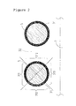
- Fig. 3 is a partially enlarged view of the coils of strand 31 coated with a hydrophilic coating agent 15.
- the coils of strand 31 are coated with the hydrophilic coating agent 15 so that the gap 32 may be formed between the side surface portions 312 of the adjacent coils of strand 31.
- the hydrophilic coating agent 15 coats the outer circumference of the coil of strand 31 so that a center 15a of a cross-section formed by the coil of strand 31 and the hydrophilic coating agent 15 may be displaced further in a direction of the outward surface portion 311 than a center 31a of a cross-section of the coil of strand 31.
- the thickness of the hydrophilic coating agent 15 becomes smaller in the order of the outward surface portion 311, the side surface portions 312, and the inward surface portion 313.
- the hydrophilic coating agent 15 is protruded in the direction of the outward surface portion 311.
- the coating thickness of the hydrophilic coating agent 15 is increased at the outward surface portion 311. Accordingly, since hydrophilicity is given to the guidewire for a long period, durability of lubricity of the guidewire 1 can be improved.
- the thickness of the hydrophilic coating agent 15 coating the inward surface portion 313 is small, a space between the core shaft and the coiled body 3 can be secured sufficiently. Accordingly, flexibility of the coiled body 3 can be further improved.
- Such a shape of the hydrophilic coating agent 15 can be formed by the following method, for example.
- the hydrophilic coating agent 15 Before coating the coils of strand 31 with the hydrophilic coating agent 15, to heighten affinity of the coils of strand 31 for the hydrophilic coating agent 15, it is preferable to irradiate the outer circumference of the coiled body 3 with ultraviolet to activate the surfaces of the coils of strand 31.
- the outward surface portion 311 of the coil of strand 31 is most activated, and the side surface portions 312 are second most activated.
- the amount of ultraviolet to be irradiated to each side surface portion 312 is less than that to be irradiated to the outward surface portion 311.
- the activation level of the side surface portion 312 is lower than that of the outward surface portion 311.
- the inward surface portion 313 is not activated since the irradiated light does not reach it. Due to such differences in activation, the activation level of the side surface portion 312 decreases from the side of the outward surface portion 311 toward the side of the inward surface portion 313.
- the larger amount of the hydrophilic coating agent 15 is attached to a more activated portion.
- the density of the hydrophilic coating agent 15 becomes lower in the order of the outward surface portion 311, the side surface portions 312, and the inward surface portion 313.
- the thickness of the hydrophilic coating agent 15 also changes in accordance with the differences in density.
- the density of the hydrophilic coating agent 15 at the side surface portion 312 gradually decreases from the side of the outward surface portion 311 toward the side of the inward surface portion 313.
- the film thickness of the hydrophilic coating agent 15 there also decreases in a similar manner.
- lubricity of the hydrophilic coating agent 15 at the outward surface portion 311 is greater than those of the side surface portions 312 and the inward surface portion 313. Also, lubricity of the hydrophilic coating agent 15 at the outward surface portion 311 can be maintained for a long period.
- the side surface portions 312 of the coil of strand 31 may be shielded by a shielding member made of a resin or a metal before irradiation of ultraviolet.
- a shielding member made of a resin or a metal before irradiation of ultraviolet.
- the entire coils of strand 31 extending in the direction of the long axis of the guidewire 1 may be coated with the hydrophilic coating agent 5 or 15.
Abstract
Description
- This application is based on Japanese Patent Application No.
2010-080081 - The present invention relates to a guidewire forming a lubricating surface.
- Conventionally, as for a guidewire that guides a catheter or the like used by being inserted in a tubular organ such as a vessel, a digestive tract, or a ureter or an intracorporeal tissue for treatment or examination, several kinds each provided on its surface with a hydrophilic coating agent to reduce a friction with the intracorporeal tissue are proposed.
- For example, in a medical instrument described in Japanese Patent Application Laid-Open No.
2004-215710 core wire 4 and coils (afirst coil 5 and a second coil 6) provided at the end portion of thecore wire 4. - Also, in a medical insertion instrument described in Japanese Patent Application Laid-Open No.
2008-237621 metal coils 2 wound around a tip portion of a wiremain body 4 to be closely attached to each other. - However, in the medical instrument merely provided with the hydrophilic coating agent as described in Japanese Patent Application Laid-Open No.
2004-215710 2008-237621 - The present invention has been made to solve the foregoing technical problems, and an object of the present invention is to provide a guidewire in which the movement of coils of strand is not inhibited, and flexibility of a coiled body is secured even in a case of being coated with a hydrophilic coating agent.
- This object is solved by a guidewire having the features of claim 1.
- A guidewire according to the invention includes a core shaft, a coiled body including coils of strand wound around an outer circumference of the core shaft, and a hydrophilic coating agent coating at least a part of the coiled body, wherein at least the part of the coiled body is coated with the hydrophilic coating agent so that adjacent coils of strand coated with the hydrophilic coating agent are spaced apart from each other by a gap which prevents a contact of the coated surfaces of the adjacent coils of strand.
- It is to be noted that each coil of strand of the coils of strand forming the coiled body means a 360° turn or winding of the strand.
- Further, according to the invention the coils of strand forming the coiled body may be wound around the outer circumference of the core shaft with a defined pitch assuring that adjacent coils of strand are spaced apart by a gap even after having been coated with the hydrophilic coating agent.
- Advantageous embodiments are subject matter of dependent claims.
- The foregoing and other objects, features, aspects and advantages of the invention will become more apparent from the following detailed description when taken in conjunction with the accompanying drawings.
-
Fig. 1 is a vertical cross-sectional view showing a guidewire according to a first embodiment of the present invention. -
Fig. 2 is a partially enlarged view of coils of strand coated with a hydrophilic coating agent of the guidewire according to the first embodiment of the present invention. -
Fig. 3 is a partially enlarged view of the coils of strand coated with a hydrophilic coating agent of a guidewire according to a second embodiment of the present invention. -
Fig. 4 shows a modification example of the second embodiment. - Preferred embodiments of the present invention will be described below with reference to the accompanying drawings, in which like reference characters designate similar or identical parts throughout the several views thereof.
- <1> A guidewire according to a first aspect includes a core shaft, a coiled body including coils of strand wound around an outer circumference of the core shaft, and a hydrophilic coating agent coating at least a part of the coiled body, wherein at least the part of the coiled body is coated with the hydrophilic coating agent so that adjacent coils of strand coated with the hydrophilic coating agent are spaced apart from each other by a gap which prevents a contact of the coated surfaces of the adjacent coils of strand.
- <2> A guidewire according to a second aspect is one in which, in the guidewire according to the first aspect, a center of a combined cross-section formed by the coil of strand and the hydrophilic coating agent is displaced further in a radial outward direction of the coiled body than a center of a cross-section of the coil of strand coated with the hydrophilic coating agent, as such.
- <3> A guidewire according to a third aspect is one in which, in the guidewire according to the first or second aspect, a thickness of the hydrophilic coating agent coating the coil of strand in an axial direction of the coiled body (a side surface direction of the coil of strand) is smaller than a thickness of the hydrophilic coating agent in a radial outward direction of the coiled body (an outward surface direction of the coil of strand).
- <4> A guidewire according to a fourth aspect is one in which, in the guidewire according to any one of the first to third aspects, a thickness of the hydrophilic coating agent coating the coil of strand in a radial inward direction of the coiled body (an inward surface direction of the coil of strand) is smaller than the thickness of the hydrophilic coating agent in an axial direction of the coiled body (a side surface direction of the coil of strand).
- <1> As described above, in the guidewire according to the first aspect, at least the part of the coiled body is coated with the hydrophilic coating agent so that the gap is formed between adjacent coils of strand. Accordingly, in this guidewire, the movement of the coils of strand is not inhibited, and flexibility of the coiled body is secured even in a case where the coils of strand are coated with the hydrophilic coating agent.
- <2> In the guidewire according to the second aspect, the center of the combined cross-section formed by the coil of strand and the hydrophilic coating agent is displaced further in the radial outward direction of the coiled body than the center of the cross-section of the coil of strand coated with the hydrophilic coating agent, as such. Accordingly, durability of lubricity of the coiled body by the hydrophilic coating agent can be improved while flexibility of the coiled body is secured.
- <3> In the guidewire according to the third aspect, the thickness of the hydrophilic coating agent coating the coil of strand in the axial direction of the coiled body (side surface direction of the coil of strand) is smaller than the thickness of the hydrophilic coating agent in the radial outward direction of the coiled body (outward surface direction of the coil of strand). Accordingly, the gap between the adjacent coils of strand can be still larger. This enables the adjacent coils of strand to be moved more freely. Also, in a case where the adjacent coils of strand come into contact with each other by bending the coiled body, portions each provided with the thin hydrophilic coating agent abut on each other. Accordingly, flexibility of the coiled body is secured further reliably.
- <4> In the guidewire according to the fourth aspect, the thickness of the hydrophilic coating agent coating the coil of strand in the radial inward direction of the coiled body (inward surface direction of the coil of strand) is smaller than the thickness of the hydrophilic coating agent in the axial direction of the coiled body (side surface direction of the coil of strand). Thus, a space between the core shaft and the coiled body can be secured sufficiently. Accordingly, flexibility of the coiled body can be further improved.
- Hereinafter, the guidewire according to the first embodiment of the present invention will be described with reference to
Figs. 1 and2 . -
Fig. 1 is a vertical cross-sectional view showing a guidewire according to an embodiment of the present invention.Fig. 2 is a partially enlarged view of the part A shown inFig. 1 . - It is to be noted that, in
Fig. 1 , the left side is referred to as "a proximal side," and the right side is referred to as "a front side" for convenience of explanation. - Also, in
Fig. 1 , the guidewire is shortened in the longitudinal direction to show the entirety schematically for ease of understanding. Accordingly, the scale ratio of the entire guidewire differs from the actual one. - In
Fig. 1 , a guidewire 1 has acore shaft 2 tapered toward the front end and a coiledbody 3 covering the tip portion of thecore shaft 2. The front end of thecore shaft 2 and the front end of thecoiled body 3 are fixed at a mostdistal portion 4. Also, thecore shaft 2 and thecoiled body 3 are fixed at brazed portions 9 (two locations) at positions on the proximal side from the mostdistal portion 4. - A material constituting the
core shaft 2 is not particularly limited. The material constituting thecore shaft 2 can be selected from a stainless steel alloy, a super elastic alloy, a cobalt alloy, a piano wire, and tungsten, for example. - A material constituting the
coiled body 3 fixed at the tip portion of thecore shaft 2 can be selected from radiopaque metals such as platinum, gold, and tungsten and radiolucent metals such as a stainless steel alloy, a super elastic alloy, a cobalt alloy, and a piano wire, for example. - Examples of a material constituting the most
distal portion 4 fixing the front end of thecore shaft 2 and the front end of the coiledbody 3 and the brazedportions 9 include an aluminum alloy brazing material, a silver brazing material, a gold brazing material, zinc, an Sn-Pb alloy, a Pb-Ag alloy, and an Sn-Ag alloy. - As shown in
Fig. 1 , the surfaces of coils ofstrand 31 forming thecoiled body 3 are coated with ahydrophilic coating agent 5. The surfaces of the coils ofstrand 31 are coated with thehydrophilic coating agent 5 so that agap 32 may be formed between the coils ofstrand 31. The coils ofstrand 31 forming thecoiled body 3 and coated with thehydrophilic coating agent 5 may be wound around the outer circumference of thecore shaft 2 with a defined pitch so that adjacent coils ofstrand 31 are spaced apart by thegap 32. - The coil of
strand 31 coated with thehydrophilic coating agent 5 will be described in detail with reference toFig. 2 . The coil ofstrand 31 has anoutward surface portion 311 corresponding to a surface directing outward, aninward surface portion 313 corresponding to a surface directing inward, andside surface portions 312 corresponding to side surfaces between theoutward surface portion 311 and theinward surface portion 313. In the present embodiment, thesurface portions side surface portions 312 are defined as follows. That is, an intersecting point of two virtual lines made by tilting a line parallel to the central axis of thecore shaft 2 45° clockwise and counterclockwise is overlapped on the center of the cross-section of the coil of strand. By doing so, the cross-section of the coil of strand is partitioned into four areas by the two virtual lines. Among the four areas, an area most distant from thecore shaft 2 is defined as theoutward surface portion 311. Also, among the four areas, an area closest to thecore shaft 2 is defined as theinward surface portion 313. Further, among the four areas, two areas other than theoutward surface portion 311 and theinward surface portion 313 are defined as theside surface portions 312. - As described above, the coils of
strand 31 are coated with thehydrophilic coating agent 5 so that thegap 32 may be formed between theside surface portions 312 of the adjacent coils ofstrand 31, - Also, the
outward surface portion 311, theside surface portions 312, and theinward surface portion 313 are coated with thehydrophilic coating agent 5. Thehydrophilic coating agent 5 coating theoutward surface portion 311, theside surface portions 312, and theinward surface portion 313 is even in thickness. - In this manner, in the guidewire of the first embodiment, the coils of
strand 31 are coated with thehydrophilic coating agent 5 so that thegap 32 may be formed between theside surface portions 312 of the adjacent coils ofstrand 31. Accordingly, the movement of the coils ofstrand 31 is not inhibited, and flexibility of thecoiled body 3 is secured although the coils ofstrand 31 are coated with thehydrophilic coating agent 5. - The coils of
strand 31 are coated with thehydrophilic coating agent 5 so that thegap 32 may be formed. Thus, when the guidewire 1 is sterilized by gas such as ethylene oxide, the gas flows into the coil from thegaps 32 of thecoiled body 3. Consequently, the inside of thecoiled body 3 can be sterilized effectively. In addition, the gas can be exhausted easily after the sterilization. - Meanwhile, at a distal portion 35 (refer to
Fig. 1 ) of thecoiled body 3, the coils ofstrand 31 can be coated with thehydrophilic coating agent 5 so that thegap 32 may be formed between the coils ofstrand 31. - In this case, the
gaps 32 are formed at thedistal portion 35 of thecoiled body 3. Thus, thedistal portion 35 of thecoiled body 3 can obtain lubricity due to hydrophilicity and can secure flexibility. - Alternatively, the
gaps 32 may be formed over the entire length of thecoiled body 3. In this case, the entire length of thecoiled body 3 becomes flexible. Thus, flexibility of the entirecoiled body 3 can be secured more reliably. - Examples of the material for the
hydrophilic coating agent 5 coating the surfaces of the coils ofstrand 31 include nonionic hydrophilic polymers such as polyvinyl alcohol, polyvinyl pyrrolidone, polyethylene glycol, polyacrylamide, polymethylacrylamide, poly (2-hydroxyethyl methacrylate), and poly (N-hydroxyethyl acrylamide), anionic hydrophilic polymers such as polyacrylic acid, polymethacrylic acid, polymaleic acid, carboxymethyl cellulose, hyaluronic acid, and poly (2-acrylamide-2-methylpropanesulfonic acid), and cationic hydrophilic polymers such as polyethyleneimine, polyallylamine, and polyvinylamine. Also, plural kinds of these hydrophilic polymers may be used as the materials for thehydrophilic coating agent 5. It is to be noted that, in a case of using plural kinds of ionic functional groups as the materials for thehydrophilic coating agent 5, it is preferable to prevent an ion complex from being formed. Thus, in the case of using ionic functional groups, it is preferable to use only either anionic or cationic functional groups. - Also, as the material for the
hydrophilic coating agent 5, a polymer obtained by conducting radical polymerization of a monomer constituting the aforementioned polymer may be used. The polymerization of a monomer facilitates control of the film thickness. Further, combination of several kinds of monomers enables control of hydrophilicity of the copolymer. A preferred polymerization when conducted is a living radical polymerization in which the molecular weight distribution is easily controlled such as a nitroxyl method, an atom transfer radical polymerization, or a reversible addition-fragmentation chain transfer polymerization. By using the living radical polymerization method, the thickness of thehydrophilic coating agent 5 on the coils ofstrand 31 can be controlled easily. - Still further, as the material for the
hydrophilic coating agent 5, a mixture of a hydrophilic polymer and a hydrophobic polymer may be used. In this case, when thehydrophilic coating agent 5 comes into contact with a fluid or a body fluid such as blood, the liquid is removed from the hydrophobic polymer and is collected to the hydrophilic polymer by the action of the hydrophobic polymer. Accordingly, lubricity of thehydrophilic coating agent 5 can be maintained. - Also, by using a copolymer of a hydrophilic monomer and a hydrophobic monomer as the hydrophilic polymer for the
hydrophilic coating agent 5, lubricity of thehydrophilic coating agent 5 can be maintained for the same reason as that in the case of using the mixture of the hydrophilic polymer and the hydrophobic polymer. - Still further, as the material for the
hydrophilic coating agent 5, a hydrophilic polymer including an ionic polymer made of either anions or cations may be used. In this case, when thehydrophilic coating agent 5 comes into contact with a fluid or a body fluid such as blood, the hydrophilic polymers are to be dispersed by electrostatic repulsion of the ionic polymers themselves. Accordingly, flexibility of thehydrophilic coating agent 5 is improved, and flexibility of thecoiled body 3 coated with thehydrophilic coating agent 5 can be secured more reliably. Also, a narrow space is generated between the hydrophilic polymers that are to be dispersed, and water molecules flow into this space. Accordingly, water retentivity of thehydrophilic coating agent 5 is improved, and lubricity of thehydrophilic coating agent 5 can be maintained. - Also, to maintain hydrophilicity of the aforementioned
hydrophilic coating agent 5, cross-linked hydrophilic polymer gel can be used as the material for thehydrophilic coating agent 5. - By gelling of the hydrophilic polymer, a fluid can be stored inside the gel. Accordingly, lubricity of the
hydrophilic coating agent 5 can be maintained. Also, the gelling contributes to increase in mechanical strength of thehydrophilic coating agent 5. Accordingly, thehydrophilic coating agent 5 can be prevented from being peeled. - A state of the hydrophilic polymer in the
hydrophilic coating agent 5 used in the present invention can be selected from a state in which the straight-chain, branched, or spherical (including dendrimer) hydrophilic polymers are fixed on thecoiled body 3 and such a state as a polymer brush in which one end of each hydrophilic polymer is fixed on the metal surface of thecoiled body 3, for example. - Among other things, the especially preferable state of the hydrophilic polymer is the polymer brush state. By using the hydrophilic polymer in the polymer brush state, the molecular weight is easily controlled. Accordingly, the
gaps 32 of thecoiled body 3 can be formed effectively, and thus flexibility of thecoiled body 3 can be secured reliably. - Examples of a method for fixing the straight-chain, branched, or spherical (including dendrimer) hydrophilic polymers on the
coiled body 3 are known methods such as a method for immersing thecoiled body 3 in a solution in which the aforementioned hydrophilic polymers are dissolved, a method for coating the coiled body with the solution with use of a brush, and a method by spray coating. - A solvent used to prepare the solution in which the aforementioned hydrophilic polymers are dissolved only needs to be a highly polar solvent. The solvent can be selected from water, methanol, ethanol, N-propanol, acetonitrile, isopropyl alcohol, dimethyl sulfoxide, dimethyl acetamide, dimethyl formamide, and N-methyl-2-pyrrolidone, for example.
- Also, examples of a method for forming the aforementioned polymer brush are known techniques referred to as a grafting-from method and a grafting-to method. The method for forming the polymer brush is not particularly limited. At the time of forming the polymer brush, the aforementioned methods can be selectively used in accordance with their respective functional characteristics.
- Next, a guidewire according to a second embodiment of the present invention will be described with reference to
Fig. 3 mainly on the difference from the first embodiment. -
Fig. 3 is a partially enlarged view of the coils ofstrand 31 coated with ahydrophilic coating agent 15. - As shown in
Fig. 3 , the coils ofstrand 31 are coated with thehydrophilic coating agent 15 so that thegap 32 may be formed between theside surface portions 312 of the adjacent coils ofstrand 31. - The
hydrophilic coating agent 15 coats the outer circumference of the coil ofstrand 31 so that acenter 15a of a cross-section formed by the coil ofstrand 31 and thehydrophilic coating agent 15 may be displaced further in a direction of theoutward surface portion 311 than acenter 31a of a cross-section of the coil ofstrand 31. The thickness of thehydrophilic coating agent 15 becomes smaller in the order of theoutward surface portion 311, theside surface portions 312, and theinward surface portion 313. - In the guidewire of the second embodiment, the
hydrophilic coating agent 15 is protruded in the direction of theoutward surface portion 311. In such a shape, the coating thickness of thehydrophilic coating agent 15 is increased at theoutward surface portion 311. Accordingly, since hydrophilicity is given to the guidewire for a long period, durability of lubricity of the guidewire 1 can be improved. - Also, since the thickness of the
hydrophilic coating agent 15 coating theinward surface portion 313 is small, a space between the core shaft and thecoiled body 3 can be secured sufficiently. Accordingly, flexibility of thecoiled body 3 can be further improved. - Such a shape of the
hydrophilic coating agent 15 can be formed by the following method, for example. - Before coating the coils of
strand 31 with thehydrophilic coating agent 15, to heighten affinity of the coils ofstrand 31 for thehydrophilic coating agent 15, it is preferable to irradiate the outer circumference of thecoiled body 3 with ultraviolet to activate the surfaces of the coils ofstrand 31. - When ultraviolet is irradiated from the outside of the
coiled body 3, theoutward surface portion 311 of the coil ofstrand 31 is most activated, and theside surface portions 312 are second most activated. The amount of ultraviolet to be irradiated to eachside surface portion 312 is less than that to be irradiated to theoutward surface portion 311. Thus, the activation level of theside surface portion 312 is lower than that of theoutward surface portion 311. Theinward surface portion 313 is not activated since the irradiated light does not reach it. Due to such differences in activation, the activation level of theside surface portion 312 decreases from the side of theoutward surface portion 311 toward the side of theinward surface portion 313. - When the
coiled body 3 activated in such a manner is coated with thehydrophilic coating agent 15, the larger amount of thehydrophilic coating agent 15 is attached to a more activated portion. Thus, the density of thehydrophilic coating agent 15 becomes lower in the order of theoutward surface portion 311, theside surface portions 312, and theinward surface portion 313. The thickness of thehydrophilic coating agent 15 also changes in accordance with the differences in density. Also, the density of thehydrophilic coating agent 15 at theside surface portion 312 gradually decreases from the side of theoutward surface portion 311 toward the side of theinward surface portion 313. The film thickness of thehydrophilic coating agent 15 there also decreases in a similar manner. - As a result, lubricity of the
hydrophilic coating agent 15 at theoutward surface portion 311 is greater than those of theside surface portions 312 and theinward surface portion 313. Also, lubricity of thehydrophilic coating agent 15 at theoutward surface portion 311 can be maintained for a long period. - Also, in a modification example of the second embodiment, the
side surface portions 312 of the coil ofstrand 31 may be shielded by a shielding member made of a resin or a metal before irradiation of ultraviolet. By irradiating the coil ofstrand 31 with ultraviolet thereafter, thehydrophilic coating agent 15 at theside surface portion 312 can be as thin as that at theinward surface portion 313, as shown inFig. 4 . This enables thegaps 32 of thecoiled body 3 to be formed further efficiently. Accordingly, flexibility of thecoiled body 3 can be secured further reliably. - Meanwhile, only a part of the coils of
strand 31 in the direction of the long axis of the guidewire 1 may be coated with thehydrophilic coating agent Figs. 1 to 4 . Alternatively, the entire coils ofstrand 31 extending in the direction of the long axis of the guidewire 1 may be coated with thehydrophilic coating agent - While the invention has been shown and described in detail, the foregoing description is in all aspects illustrative and not restrictive. It is therefore understood that numerous modifications and variations can be devised without departing from the spirit and scope of the invention.
-
- 1
- guidewire
- 2
- core shaft
- 3
- coiled body
- 31
- coil of strand
- 31a
- center of a cross-section of a coil of strand
- 311
- outward surface portion
- 312
- side surface portion
- 313
- inward surface portion
- 4
- most distal portion
- 5, 15
- hydrophilic coating agent
- 15a
- center of a cross-section of a coil of strand and a hydrophilic coating agent
Claims (4)
- A guidewire (1) comprising:a core shaft (2);a coiled body (3) including coils of strand wound around an outer circumference of the core shaft (2); anda hydrophilic coating agent (5; 15) coating at least a part of the coiled body (3), characterized in thatat least the part of the coiled body (3) is coated with the hydrophilic coating agent (5; 15) so that adjacent coils of strand (31) coated with the hydrophilic coating agent (5; 15) are spaced apart from each other by a gap (32) which prevents a contact of the coated surfaces of the adjacent coils of strand (31).
- The guidewire (1) according to claim 1, wherein a center (15a) of a combined cross-section formed by the coil of strand (31) and the hydrophilic coating agent (15) is displaced further in a radial outward direction of the coiled body (3) than a center (31a) of a cross-section of the coil of strand (31) as such.
- The guidewire (1) according to claim 1 or 2, wherein a thickness of the hydrophilic coating agent (15) coating the coil of strand (31) in an axial direction of the coiled body (3) is smaller than a thickness of the hydrophilic coating agent (15) in a radial outward direction of the coiled body (3).
- The guidewire (1) according to any one of claims 1 to 3, wherein a thickness of the hydrophilic coating agent (15) coating the coil of the strand (31) in a radial inward direction of the coiled body (3) is smaller than a thickness of the hydrophilic coating agent (15) in an axial direction of the coiled body (3).
Applications Claiming Priority (1)
| Application Number | Priority Date | Filing Date | Title |
|---|---|---|---|
| JP2010080081A JP4905740B2 (en) | 2010-03-31 | 2010-03-31 | Guide wire |
Publications (2)
| Publication Number | Publication Date |
|---|---|
| EP2371403A2 true EP2371403A2 (en) | 2011-10-05 |
| EP2371403A3 EP2371403A3 (en) | 2013-07-17 |
Family
ID=44484240
Family Applications (1)
| Application Number | Title | Priority Date | Filing Date |
|---|---|---|---|
| EP11158657.4A Withdrawn EP2371403A3 (en) | 2010-03-31 | 2011-03-17 | Guidewire |
Country Status (4)
| Country | Link |
|---|---|
| US (1) | US20110245729A1 (en) |
| EP (1) | EP2371403A3 (en) |
| JP (1) | JP4905740B2 (en) |
| CN (1) | CN102205164A (en) |
Families Citing this family (5)
| Publication number | Priority date | Publication date | Assignee | Title |
|---|---|---|---|---|
| JP5952562B2 (en) * | 2012-01-05 | 2016-07-13 | 株式会社グッドマン | Catheter and method for manufacturing catheter |
| JP5896479B2 (en) * | 2013-09-25 | 2016-03-30 | 朝日インテック株式会社 | Guide wire |
| JP5904672B2 (en) | 2013-09-25 | 2016-04-20 | 朝日インテック株式会社 | Guide wire |
| JP6275008B2 (en) * | 2014-09-16 | 2018-02-07 | 朝日インテック株式会社 | Guide wire |
| US20170065750A1 (en) * | 2015-09-03 | 2017-03-09 | Becton, Dickinson And Company | Iv anticoagulant treatment systems and methods |
Citations (3)
| Publication number | Priority date | Publication date | Assignee | Title |
|---|---|---|---|---|
| JP2004215710A (en) | 2003-01-09 | 2004-08-05 | Nippon Cable Syst Inc | Lubricating coating agent and medical instrument showing lubrication in moisture absorption |
| JP2008237621A (en) | 2007-03-27 | 2008-10-09 | Japan Lifeline Co Ltd | Medical insertion instrument and its production method |
| JP2010080081A (en) | 2008-09-24 | 2010-04-08 | Panasonic Corp | Secondary battery |
Family Cites Families (6)
| Publication number | Priority date | Publication date | Assignee | Title |
|---|---|---|---|---|
| US4534363A (en) * | 1982-04-29 | 1985-08-13 | Cordis Corporation | Coating for angiographic guidewire |
| US6203505B1 (en) * | 1998-06-05 | 2001-03-20 | Advanced Cardiovascular Systems, Inc. | Guidewires having a vapor deposited primer coat |
| US6494894B2 (en) * | 2000-03-16 | 2002-12-17 | Scimed Life Systems, Inc. | Coated wire |
| US7141024B2 (en) * | 2002-11-06 | 2006-11-28 | Benny Gaber | Maneuverable-coiled guidewire |
| US7182735B2 (en) * | 2003-02-26 | 2007-02-27 | Scimed Life Systems, Inc. | Elongated intracorporal medical device |
| JP5248932B2 (en) * | 2008-06-20 | 2013-07-31 | 株式会社パイオラックスメディカルデバイス | Guide wire and manufacturing method thereof |
-
2010
- 2010-03-31 JP JP2010080081A patent/JP4905740B2/en active Active
-
2011
- 2011-02-11 CN CN2011100365952A patent/CN102205164A/en active Pending
- 2011-02-25 US US13/035,215 patent/US20110245729A1/en not_active Abandoned
- 2011-03-17 EP EP11158657.4A patent/EP2371403A3/en not_active Withdrawn
Patent Citations (3)
| Publication number | Priority date | Publication date | Assignee | Title |
|---|---|---|---|---|
| JP2004215710A (en) | 2003-01-09 | 2004-08-05 | Nippon Cable Syst Inc | Lubricating coating agent and medical instrument showing lubrication in moisture absorption |
| JP2008237621A (en) | 2007-03-27 | 2008-10-09 | Japan Lifeline Co Ltd | Medical insertion instrument and its production method |
| JP2010080081A (en) | 2008-09-24 | 2010-04-08 | Panasonic Corp | Secondary battery |
Also Published As
| Publication number | Publication date |
|---|---|
| JP2011212034A (en) | 2011-10-27 |
| EP2371403A3 (en) | 2013-07-17 |
| US20110245729A1 (en) | 2011-10-06 |
| JP4905740B2 (en) | 2012-03-28 |
| CN102205164A (en) | 2011-10-05 |
Similar Documents
| Publication | Publication Date | Title |
|---|---|---|
| EP2371402B1 (en) | Guidewire coating presenting a crosslinking gradient | |
| JP2992251B2 (en) | Micro braided guidewire | |
| EP2371403A2 (en) | Guidewire | |
| JP3645107B2 (en) | Medical tube | |
| JP3830945B2 (en) | Composite braided guidewire | |
| US20160008585A1 (en) | Guide wire | |
| JP2005523981A5 (en) | ||
| US20140188004A1 (en) | Guidewire | |
| US20120245488A1 (en) | Guidewire | |
| TWI517869B (en) | Medical guide wire | |
| JP2012070979A (en) | Guide wire | |
| US10201680B2 (en) | Catheter | |
| JP2009233200A (en) | Guide wire | |
| US20190262588A1 (en) | Guide wire | |
| JP2006516454A (en) | In-vivo device with ionomer polymer sleeve | |
| JP4436047B2 (en) | Medical hydrogels composed of different polymer compounds | |
| WO2022092002A1 (en) | Guide wire and method of manufacturing guide wire | |
| JP7474775B2 (en) | Guidewires | |
| WO2021117657A1 (en) | Guide wire | |
| JP2024040728A (en) | catheter | |
| WO2019130775A1 (en) | Guide wire | |
| JP2006129935A (en) | Medical guidewire | |
| JPWO2019155550A1 (en) | Guide wire | |
| JP2020072769A (en) | catheter |
Legal Events
| Date | Code | Title | Description |
|---|---|---|---|
| PUAI | Public reference made under article 153(3) epc to a published international application that has entered the european phase |
Free format text: ORIGINAL CODE: 0009012 |
|
| AK | Designated contracting states |
Kind code of ref document: A2 Designated state(s): AL AT BE BG CH CY CZ DE DK EE ES FI FR GB GR HR HU IE IS IT LI LT LU LV MC MK MT NL NO PL PT RO RS SE SI SK SM TR |
|
| AX | Request for extension of the european patent |
Extension state: BA ME |
|
| PUAL | Search report despatched |
Free format text: ORIGINAL CODE: 0009013 |
|
| AK | Designated contracting states |
Kind code of ref document: A3 Designated state(s): AL AT BE BG CH CY CZ DE DK EE ES FI FR GB GR HR HU IE IS IT LI LT LU LV MC MK MT NL NO PL PT RO RS SE SI SK SM TR |
|
| AX | Request for extension of the european patent |
Extension state: BA ME |
|
| RIC1 | Information provided on ipc code assigned before grant |
Ipc: A61M 25/09 20060101ALI20130613BHEP Ipc: A61L 31/10 20060101AFI20130613BHEP Ipc: A61L 31/14 20060101ALI20130613BHEP |
|
| STAA | Information on the status of an ep patent application or granted ep patent |
Free format text: STATUS: THE APPLICATION IS DEEMED TO BE WITHDRAWN |
|
| 18D | Application deemed to be withdrawn |
Effective date: 20140118 |