EP2371316A1 - Surgical instrument, in particular electro-surgical instrument - Google Patents
Surgical instrument, in particular electro-surgical instrument Download PDFInfo
- Publication number
- EP2371316A1 EP2371316A1 EP11159304A EP11159304A EP2371316A1 EP 2371316 A1 EP2371316 A1 EP 2371316A1 EP 11159304 A EP11159304 A EP 11159304A EP 11159304 A EP11159304 A EP 11159304A EP 2371316 A1 EP2371316 A1 EP 2371316A1
- Authority
- EP
- European Patent Office
- Prior art keywords
- functional unit
- actuating element
- surgical instrument
- instrument
- electrosurgical instrument
- Prior art date
- Legal status (The legal status is an assumption and is not a legal conclusion. Google has not performed a legal analysis and makes no representation as to the accuracy of the status listed.)
- Granted
Links
Images


Classifications
-
- A—HUMAN NECESSITIES
- A61—MEDICAL OR VETERINARY SCIENCE; HYGIENE
- A61B—DIAGNOSIS; SURGERY; IDENTIFICATION
- A61B18/00—Surgical instruments, devices or methods for transferring non-mechanical forms of energy to or from the body
- A61B18/04—Surgical instruments, devices or methods for transferring non-mechanical forms of energy to or from the body by heating
- A61B18/12—Surgical instruments, devices or methods for transferring non-mechanical forms of energy to or from the body by heating by passing a current through the tissue to be heated, e.g. high-frequency current
- A61B18/14—Probes or electrodes therefor
- A61B18/1442—Probes having pivoting end effectors, e.g. forceps
-
- A—HUMAN NECESSITIES
- A61—MEDICAL OR VETERINARY SCIENCE; HYGIENE
- A61B—DIAGNOSIS; SURGERY; IDENTIFICATION
- A61B17/00—Surgical instruments, devices or methods, e.g. tourniquets
- A61B17/00234—Surgical instruments, devices or methods, e.g. tourniquets for minimally invasive surgery
- A61B2017/00353—Surgical instruments, devices or methods, e.g. tourniquets for minimally invasive surgery one mechanical instrument performing multiple functions, e.g. cutting and grasping
-
- A—HUMAN NECESSITIES
- A61—MEDICAL OR VETERINARY SCIENCE; HYGIENE
- A61B—DIAGNOSIS; SURGERY; IDENTIFICATION
- A61B17/00—Surgical instruments, devices or methods, e.g. tourniquets
- A61B17/28—Surgical forceps
- A61B17/29—Forceps for use in minimally invasive surgery
- A61B17/2909—Handles
- A61B2017/2912—Handles transmission of forces to actuating rod or piston
- A61B2017/2919—Handles transmission of forces to actuating rod or piston details of linkages or pivot points
- A61B2017/2922—Handles transmission of forces to actuating rod or piston details of linkages or pivot points toggle linkages
-
- A—HUMAN NECESSITIES
- A61—MEDICAL OR VETERINARY SCIENCE; HYGIENE
- A61B—DIAGNOSIS; SURGERY; IDENTIFICATION
- A61B17/00—Surgical instruments, devices or methods, e.g. tourniquets
- A61B17/28—Surgical forceps
- A61B17/29—Forceps for use in minimally invasive surgery
- A61B17/2909—Handles
- A61B2017/2912—Handles transmission of forces to actuating rod or piston
- A61B2017/2923—Toothed members, e.g. rack and pinion
-
- A—HUMAN NECESSITIES
- A61—MEDICAL OR VETERINARY SCIENCE; HYGIENE
- A61B—DIAGNOSIS; SURGERY; IDENTIFICATION
- A61B18/00—Surgical instruments, devices or methods for transferring non-mechanical forms of energy to or from the body
- A61B2018/0091—Handpieces of the surgical instrument or device
- A61B2018/00916—Handpieces of the surgical instrument or device with means for switching or controlling the main function of the instrument or device
-
- A—HUMAN NECESSITIES
- A61—MEDICAL OR VETERINARY SCIENCE; HYGIENE
- A61B—DIAGNOSIS; SURGERY; IDENTIFICATION
- A61B18/00—Surgical instruments, devices or methods for transferring non-mechanical forms of energy to or from the body
- A61B18/04—Surgical instruments, devices or methods for transferring non-mechanical forms of energy to or from the body by heating
- A61B18/12—Surgical instruments, devices or methods for transferring non-mechanical forms of energy to or from the body by heating by passing a current through the tissue to be heated, e.g. high-frequency current
- A61B18/14—Probes or electrodes therefor
- A61B2018/1405—Electrodes having a specific shape
- A61B2018/1412—Blade
-
- A—HUMAN NECESSITIES
- A61—MEDICAL OR VETERINARY SCIENCE; HYGIENE
- A61B—DIAGNOSIS; SURGERY; IDENTIFICATION
- A61B18/00—Surgical instruments, devices or methods for transferring non-mechanical forms of energy to or from the body
- A61B18/04—Surgical instruments, devices or methods for transferring non-mechanical forms of energy to or from the body by heating
- A61B18/12—Surgical instruments, devices or methods for transferring non-mechanical forms of energy to or from the body by heating by passing a current through the tissue to be heated, e.g. high-frequency current
- A61B18/14—Probes or electrodes therefor
- A61B18/1442—Probes having pivoting end effectors, e.g. forceps
- A61B2018/1452—Probes having pivoting end effectors, e.g. forceps including means for cutting
- A61B2018/1455—Probes having pivoting end effectors, e.g. forceps including means for cutting having a moving blade for cutting tissue grasped by the jaws
Definitions
- the invention relates to a surgical instrument, in particular electrosurgical instrument, according to claim 1.
- Surgical instruments that combine multiple functions are known in the art. In such combined instruments, there is no need to switch between the "individual instruments” needed at a given time. For example, laparoscopic operations, where instrument replacement is usually associated with costly extraction and insertion into the trocar, can be performed more efficiently. For example, combined instruments for vessel sealing and for cutting tissue are known.
- tissue that is to be removed.
- tissue is grasped and coagulated in a first step.
- the coagulated portion is severed with a cutting instrument.
- the coagulation takes place to close blood vessels and prevent bleeding during cutting.
- Such an instrument requires a first functional unit for gripping and a second functional unit for cutting the tissue, wherein a mechanism for Transmission of force or movement must be provided.
- the corresponding force can be expended by the user through controls on a handle, such as a hand-trigger or a fingerprint.
- actuating elements are provided, wherein each actuating element is associated with a functional unit.
- a hand trigger for grasping a finger trigger for cutting and a separate coagulation switch may be provided.
- the separate design of the actuators is perceived as disadvantageous, since the operation often has to be interrupted because, for example, a liquid gripping and cutting in one go is not possible.
- the user is limited, for example, when the index finger is used for cutting and is no longer available for the activation of the coagulation process.
- the various actuators lead to additional costs and relatively "bulky" instruments. Overall, the instrument in the application is unclear.
- 7,628,791 B2 Although proposed locking devices, but they only allow a catch before the cutting process begins. During the cutting process, a corresponding locking is not possible and would also be disadvantageous, as this would have the consequence in the known device that the cutting blade could not be moved back. Overall, the user is in accordance with the operation of the instrument US Pat. No. 7,628,791 B2 comparatively limited, for example, care must be taken during the cutting of the tissue that the tissue is sufficiently maintained.
- a surgical instrument in particular an electrosurgical instrument
- an actuating element for actuating at least one first and one second functional unit
- the actuating element is translationally and / or rotationally movable within a movement range, wherein a movement within a first portion of the Movement range, the first functional unit is actuated and by a movement within a second portion of the movement range, the second functional unit is actuated
- a Umkopplungsvorraum is provided such that, as a result of movement of the actuating element by a Umkopplungs Scheme between the first and second partial area an operative connection between the first functional unit and actuator can be interrupted and an operative connection between the second functional unit and actuator can be made.
- An essential point of the invention is that, due to the intended coupling device, a movement within the first partial area has no effect on the second functional unit, and vice versa, that a movement within the second partial area has no effect on the first functional unit.
- the user can thus focus on performing the first or second function, without having to take into account each other's function.
- For actuation of the functional units only one actuating element is necessary. Overall, the operability of the surgical instrument over the prior art is improved.
- an operative connection between the actuator and the first and / or second functional unit can be made or interrupted.
- At least one locking device is provided such that the first functional unit or a subcomponent thereof is locked in a movement of the actuating element within the second portion and possibly vice versa that the second functional unit or a sub-component thereof is locked in a movement of the actuating element within the first portion
- the locking device may be part of the Umkopplungsvorraum. Such locking further facilitates the operation of the surgical instrument. If, for example, the first functional unit is a retaining device or gripping device for a tissue, then it is ensured that the retaining device is constant with regard to its exerted force and / or position.
- the locking device or the coupling device comprises a toggle device.
- the toggle device can be designed such that a locking or decoupling can take place when a dead center is exceeded.
- the dead point in this case defines the transposition range.
- the Umkopplungs Symposium be punctiform, wherein the coupling can take place when the corresponding Umkopplungs.
- the locking or decoupling using a toggle device is structurally particularly simple and can be done in a simple manner.
- the coupling device or locking device comprises a guide rail, in which the actuating element, in particular (essentially) in a plane of movement, can be guided.
- the guide rail can be designed such that a decoupling or locking, possibly in cooperation with other components, can be triggered by a movement of the actuating element within the at least one guide rail.
- Such a guide rail facilitates the decoupling or locking and thus the operation of the surgical instrument.
- the guide rail V-shaped or U-shaped, wherein a first V / U-leg is shorter than a second V / U-leg.
- the guide rail is formed such that the locking is realized when the guide rail is disposed within the first, shorter V- / U-leg.
- the guide rail may be formed such that the lock is released when the actuating element is arranged or transferred into the second, longer V- / U-shaped legs.
- the guide rail be formed such that at a transfer from one leg into the other at the same time the coupling takes place.
- Such guide rails are structurally simple and facilitate the operation.
- the guide rail is in particular an integral part of a housing element, preferably a handle shell.
- the first / second functional unit comprises a cutting device, such as a mechanical cutting device or a laser cutting device, and / or a gripping device and / or a coagulation device, in particular RF coagulation device, and / or a water jet device, in particular a water jet cutting device, and / / or an optical device, such as a camera or a lighting device, and / or a suction device, and / or a flushing device, and / or a cryoprobe, and / or a biopsy device, such as a biopsy probe or a Biopbaldreiokfer, and / or a preferably monopolar cutting electrode.
- the first functional unit comprises a retaining device and the second functional unit comprises a cutting device.
- At least one rack and at least one gear for transmitting the action between the actuating element and at least one functional unit are provided.
- the gear is engageable with a row of teeth, which is preferably connected to a / the housing element, more preferably one / the handle shell, and in particular integrally formed with the housing element or the handle shell, such that a rotation of the gear translational Displacement of the rack relative to the housing element or the handle causes.
- a row of teeth which is preferably connected to a / the housing element, more preferably one / the handle shell, and in particular integrally formed with the housing element or the handle shell, such that a rotation of the gear translational Displacement of the rack relative to the housing element or the handle causes.
- the first / second functional unit in particular the cutting device and / or the retaining device, can be moved in two different directions by actuating the actuating element, preferably in any position within the corresponding partial area and / or actively. This further facilitates the operation of the surgical instrument.
- At least one third functional unit for example a coagulation device, can be actuated by a further (separate) actuating element.
- a further (separate) actuating element can take place independently of the actuation of the first or second functional unit. This facilitates the operation.
- the actuator may include a hand-trigger for ease of operation.
- the actuating element can be rotatable about at least two spaced rotational axes. By means of such a change in the axis of rotation, the same actuating element can apply force to different components in a particularly simple manner.
- the actuating element for actuating the first functional unit is rotatable about a first axis and for actuating the second functional unit about a second axis.
- the decoupling may include the displacement of the axes of rotation. The operation of the individual functional units is connected in this case only with little design effort.
- one / the second axis of rotation lies on a central axis of the toggle joint.
- one / the first / second rotation axis can be arranged within the guide rail, in particular within the shorter U / V leg.
- at least a small translation take place, so that the rotation axis shifts during the rotation.
- the displacement in this case is preferably less than 5 mm, more preferably less than 3 mm. If the actuating element is rotatable about the central axis of the toggle joint, an actuation of the corresponding functional unit can be carried out particularly easily.
- the actuating element is rotatable and, in particular via the toggle lever joint, drive a sliding device translationally.
- the sliding device can trigger a specific function, in particular via connecting elements, such as a push rod, and reduces the effort in the production.
- At least one spring element is provided such that a force of the actuating element can be transmitted via the spring element to the first / second functional unit.
- the force of the actuating element can be buffered or stored.
- such a spring element can pressurize the first / second functional unit when the first / second functional element is in a locked position.
- the functional unit is a retaining device, the tissue can be held reliably and with a constant force, without the user having to act on it.
- At least one spring element preferably a tension spring provided in such a way that the spring element exerts a restoring force upon displacement of the functional unit.
- a spring element allows in a simple manner that the corresponding function, for example, the retention of the tissue is achieved or deactivated without an active holding the user.
- the actuating element is designed such that the movement within the first portion and / or the second portion and / or the Umkopplungs Kunststoffes in a plane is feasible. This reduces the complexity of the application.
- the Umkopplungs- and / or locking device are reversible designed such that a reversal of motion of the actuating element leads to a leading back to the initial state coupling or to a cancellation of the lock. This facilitates the handling of the instrument.
- the surgical instrument allows ergonomic and effective working. Due to the (mechanical) decoupling of the subregions, no forces are transmitted to the respective other functional unit or the actuating element. For example, although the user first has to apply force to grasp the tissue (generally to actuate the first functional unit). After locking, however, it can work independently of this closing force (force) in the second subarea.
- the functions can be performed with the same "body parts” (for example middle and / or ring and / or little finger), leaving other "body parts” free for use. For example, the index finger when operating a cutting device remain free, so that it can be used to operate a coagulation switch, analogous to the withdrawal of a gun.
- a separate control element may be provided, possibly without an associated mechanical functional unit.
- an electrosurgical generator may be provided which generates an RF current which is conducted via the instrument through the gripped tissue.
- the HF current can be applied in a monopolar or bipolar mode.
- the signal for coagulation is usually by a finger switch, possibly also on the handle or by a foot switch.
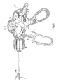
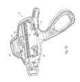
- Fig. 1 shows an electrosurgical instrument in a side view, which is designed for grasping tissue (first function), coagulation (third function) and cutting (second function).
- the gripping and cutting of tissue is carried out by a common actuator 5, specifically a manual trigger.
- the coagulation is controlled by a second actuator 6, specifically a fingerprint.
- the manual trigger 5 and the finger trigger 6 are compared with a handle housing 7, which has two opposite handles 8, arranged movable.
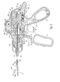
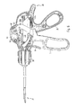
- the Fig. 2 and 3 show views of the electrosurgical instrument, wherein the manual trigger 5 is arranged in a first position.
- the manual trigger 5 is used for actuating both a gripping device 100 (as a first functional unit) and a cutting device 200 (as a second functional unit).
- the gripping device 100 comprises a jaw part 101, on which a gripper rod or a gripper wire 102 is arranged, so that a pulling movement in the direction of a proximal end 30 results in a closing movement of the jaw part 101 and vice versa a pushing movement in the direction of a distal end 31 an opening of the Jaw 101.
- a proximal Element / section is understood to be an element / section that lies farther away from the jaw part 101 than a corresponding distal element or a corresponding proximal section.
- the gripping device 100 further includes a pulling sleeve 104 connected to a proximal end of the gripping device wire 102.
- the tension sleeve 104 is connected to a spring plate 106 at a proximal end 105 (for example via a thread).
- a sleeve 108 At a distal end 107 of the tension sleeve 104, the latter is (slidably) guided in a sleeve 108 (threaded sleeve) and then proximally in a second spring plate 109.
- a first spring element 110 (concretely a coil spring) is arranged between the first spring plate 106 and the second spring plate 109.
- the tension sleeve 104, the first spring plate 106, the second spring plate 109 and the first spring element 110 are in turn slidably mounted in a recess 111 of a transmission element 112.
- the transmission element 112 is mounted within the handle shells 8, specifically within molded on this handle shell recesses 32, slidably.
- For sliding mounting of the transmission element 112 serve transmission element pin 113, which in the rail-like handle shell recesses 32 (see Fig. 2 ) are guided.
- the transmission element 112 has a transmission element stop 114 (possibly a plurality) which exerts a force on a distal end of the second spring plate 109 during a movement of the transmission element 112 in the proximal direction, which in turn indirectly via the first spring element 110, the first spring plate 106 and the pulling sleeve 104 exerts a pulling force on the picking device wire 102 in the proximal direction.
- a transmission element stop 114 possibly a plurality which exerts a force on a distal end of the second spring plate 109 during a movement of the transmission element 112 in the proximal direction, which in turn indirectly via the first spring element 110, the first spring plate 106 and the pulling sleeve 104 exerts a pulling force on the picking device wire 102 in the proximal direction.
- the pulling force acting on the picker wire 102 causes the jaw member 101 to close until either it is completely closed or against a tissue to be gripped. Fluctuations in fabric thicknesses can be compensated particularly simply by the spring element 110 without the fabric being too loose or too tight.
- the spring element thus also has an energy storage function, so that the user is facilitated in a structurally simple way, the operation of the instrument.
- a tension spring 115 (concretely a helical tension spring) is suspended, on the one hand, on the handle shells 8 and on the handle shells pins 33 arranged thereon, and on the other hand a proximal end 116 of the transmission element 112 such that a displacement of the transmission element 112 in the proximal direction counteracts a spring force of the tension spring 115.
- This can be done in the position according to Fig. 2 and 3
- Particularly easy automatic opening of the jaw part 101 can be ensured. This facilitates the operation of the electrosurgical instrument.
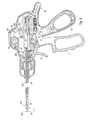
- the cutter 200 includes a knife 201 connected to a cutter bar or cutter wire 202.
- a proximal end 203 of the quick device wire 202 is connected to a transfer element 206 (via a threaded sleeve 204 and a pin 205).
- a displacement of the transfer member 206 in the distal direction via the cutter wire 202 results in a displacement of the knife 201 in the distal direction, so that tissue held in the jaw member 101 can be severed.
- a second spring element 208 is arranged in a transfer element recess 207, wherein a proximal end of the second spring element 208 strikes against a proximal end of the transfer element 206 and a distal end of the second spring element 208 abuts against a pin 34 which is stationary (for example integrally formed) with the pin Grips 8 is connected.
- the handles 8 further form a handle member 35, for example, for receiving a thumb of the user.
- a rotary member 36 is provided, with which the jaw part 101 and / or the knife 201 can be rotated.
- the toggle device 37 comprises a toggle plate 38 (substantially triangular).
- the toggle plate 38 includes a first toggle plate bore 39 and a second toggle plate bore 40, and toggle plate pins 41 (in FIG Fig. 3 dashed lines drawn).
- first toggle plate hole a stationary with the manual trigger 5 connected manual trigger 42 is guided.
- second toggle lever bore 40 a fixedly connected to the handles 8 handle shell pin 43 is guided.
- the (outwardly standing) toggle plate pins 41 are in a ellessplattenausEnglishung 44 a first transfer plate 45 and a ellessplattenausnaturalung 46 a second transfer plate 47 out (dashed lines).
- the transfer plate recess 44, 46 or the transfer plates 45, 47 lie one above the other in the figures.
- the transfer plates 45, 47 have second transfer plate recesses 48, 49 (in FIG Fig. 3 dashed lines), which are guided by the stationary connected to the transmission element 112 pins 117.
- the toggle device 37 thus comprises a first toggle joint 50 comprising the first toggle lever bore 39 and the puller pin 42, a second toggle joint 51 comprising the second toggle plate bore 40 and the handle cup pin 43, a third toggle joint 52 comprising the toggle plate pins 41 and the transmission plate recesses 44, 46, and a fourth toggle joint 53 comprising the second Consequentlysplattenausnaturalept 48, 49 and the pins 117 of the transmission element 112.
- the toggle joints 50-53 may also be formed differently from the construction shown here.
- the first toggle joint 50 is stationary relative to the hand trigger 5, the second toggle joint 51 is stationary relative to the handle shells 8, the fourth toggle joint 53 is stationary relative to the transmission element 112, whereas the third toggle joint 52 relative to the hand trigger 5, the handles 8 and the transmission element 112nd is mobile.
- the hand trigger 5 has one (or more) hand trigger pin 54 (see Fig. 2 ), which is held in a V-shaped recess 55 with a shorter V-leg 56 and a longer V-leg 57 (see Fig. 10 ). In the position according to Fig. 2 and 3 the manual trigger pin 54 is held in the shorter V-leg 56 and is locked by this. A closing movement of the manual trigger 5 thereby leads to a rotation of the manual trigger 5 about a first axis of rotation 58 (see FIG Fig. 2 ) defined by the manual pen 54. As a result of a rotation about the first axis of rotation 58, the transfer plates 45, 47 are stretched in relation to the toggle plate 38 (see FIG Fig.
- the dead point is achieved, for example, when a connecting line between the third and fourth toggle joint 52, 53 is perpendicular to a connecting line between the first and second toggle joint 50, 51 (this position is an intermediate position between the position in FIG Fig. 4 and 5 on the one hand and 6 and 7 on the other hand).
- the V-shaped recess 55 is arranged and formed such that the manual trigger pin 54 in the position according to FIG Fig. 7 and 8th is no longer locked (or the lock is resolved). Thus, in the position according to Fig. 7 and 8th the hand trigger 5 to rotate about a second axis of rotation 59, which is defined by the manual trigger 42.
- the gear 60 is in the distal direction to an end position according to Fig. 8 and 9 moved within the elongated handle cup recess 63.
- the gear 60 is rotated by the displacement and may also displace the transfer member 206 having transfer member teeth 209 in the distal direction.
- the knife 201 is thus displaced in the distal direction for severing the tissue.
- the transfer element 206 can be displaced by a comparatively small displacement of the gear 60 or a comparatively small rotation of the manual trigger 5 about the second rotation axis 59 by a comparatively large distance. This facilitates the operation of the electrosurgical instrument.
- the position according to Fig. 6 and 7 on the one hand and according to Fig. 8 and 9 on the other hand define at least a portion of a second portion of a range of movement of the manual trigger 5, in which only the cutting device 200 is actuated.
- a first subset of the range of motion defined by the positions in Fig. 2 and 3 on the one hand and the FIGS. 4 and 5 on the other hand at least partially defined, only the gripping device 100 can be operated.
- a Umkopplungs Scheme is defined, within which when closing the manual trigger 5 a locking of the gripping device 100 is made and a locking of the cutting device 200 is dissolved.
- a third functional unit specifically a coagulation functional unit, can be operated separately from the manual trigger 5 via the second actuating element (the finger trigger) 6.
- the gripping device 100 can be arbitrarily moved back and forth in the first subregion, the cutting device 200 in the second subregion of the movement subregion, which further improves operability.
- the knife 201 can be moved back and forth for severing, resulting in a comparatively smooth cut edge. Even when gripping tissue is ensured that in any position, the jaw part 101 can be opened further or further closed.
- two jaw halves of the jaw part 101 serve.
- the jaw part halves can be opened and closed. If the manual trigger 5 is pulled, for example via a closing movement of the user's hand, the jaw part 101 is closed via the gripping device 100. So tissue can be grasped and coagulated. Coagulation does not necessarily require a mechanical functional unit.
- the toggle lever device 37 is used for latching. If the manual trigger 5 is in the second partial area and thus drives the cutting device 200, it is decoupled from the first partial region or the gripping device 100. If the manual trigger 5 is pulled further in the second partial region, it moves the cutter 200 distalls the knife 201 distally through the clamped tissue and cuts it. If the manual trigger 5 is moved back in the direction of the latching point, the knife 201 is returned again. If the manual trigger 5 is moved beyond the latching point, the catch releases and the jaw halves can be opened.
- the first functional unit is preferably actuatable by stretching the toggle joint and the second functional unit by a rotation about the second axis of rotation.
- the gripper wire 102 and / or the cutter wire 202 are preferably guided in a tubular shaft 68.
Abstract
Description
Die Erfindung betrifft ein chirurgisches Instrument, insbesondere elektrochirurgisches Instrument, nach Anspruch 1.The invention relates to a surgical instrument, in particular electrosurgical instrument, according to claim 1.
Chirurgische Instrumente, die mehrere Funktionen zusammenfassen, sind im Stand der Technik bekannt. Bei derartig kombinierten Instrumenten entfällt ein Wechsel zwischen den zu einem bestimmten Zeitpunkt benötigten "Einzelinstrumenten". Beispielsweise laparoskopische Operationen, bei denen üblicherweise ein Instrumentenwechsel mit einem aufwändiges Herausziehen und Einführen in den Trokar verbunden ist, können so effizienter durchgeführt werden. Bekannt sind beispielsweise kombinierte Instrumente zur Gefäßversiegelung und zum Schneiden von Gewebe.Surgical instruments that combine multiple functions are known in the art. In such combined instruments, there is no need to switch between the "individual instruments" needed at a given time. For example, laparoscopic operations, where instrument replacement is usually associated with costly extraction and insertion into the trocar, can be performed more efficiently. For example, combined instruments for vessel sealing and for cutting tissue are known.
Eine häufige Anwendung für derartige Instrumente ist das Absetzen von Gewebe, das entnommen werden soll. Beim Absetzen wird in einem ersten Schritt Gewebe gegriffen und koaguliert. In einem zweiten Schritt wird der koagulierte Abschnitt mit einem Schneidinstrument durchtrennt. Die Koagulation erfolgt dabei, um Blutgefäße zu verschließen und eine Blutung beim Schneiden zu verhindern. Diese Schritte werden so oft wiederholt, bis das Gewebebündel vom Körper abgetrennt ist. Derartige Verfahren sind Standard bei Krebserkrankungen, beispielsweise bei einer Hysterektomie, bei der die Gebärmutter entfernt wird.A common application for such instruments is the removal of tissue that is to be removed. Upon settling, tissue is grasped and coagulated in a first step. In a second step, the coagulated portion is severed with a cutting instrument. The coagulation takes place to close blood vessels and prevent bleeding during cutting. These steps are repeated until the tissue bundle is separated from the body. Such methods are standard in cancers, for example, in a hysterectomy in which the uterus is removed.
Ein solches Instrument benötigt eine erste Funktionseinheit für das Greifen und eine zweite Funktionseinheit für das Schneiden des Gewebes, wobei eine Mechanik zur Übertragung von Kraft bzw. Bewegung vorgesehen sein muss. Die entsprechende Kraft kann vom Anwender durch Bedienelemente an einem Handgriff, beispielsweise einen Handabzug oder einen Fingerabzug, aufgewendet werden.Such an instrument requires a first functional unit for gripping and a second functional unit for cutting the tissue, wherein a mechanism for Transmission of force or movement must be provided. The corresponding force can be expended by the user through controls on a handle, such as a hand-trigger or a fingerprint.
Üblicherweise sind bei chirurgischen Instrumenten gemäß dem Stand der Technik mehrere Betätigungselemente vorgesehen, wobei jedes Betätigungselement einer Funktionseinheit zugeordnet ist. Dadurch können die Funktionseinheiten getrennt bedient werden. Beispielsweise können ein Handabzug zum Greifen, ein Fingerabzug zum Schneiden und ein separater Koagulationsschalter vorgesehen sein. Die separate Ausbildung der Betätigungselemente wird als nachteilig empfunden, da die Operation oftmals unterbrochen werden muss, weil beispielsweise ein flüssiges Greifen und Schneiden in einem Zug nicht möglich ist. Weiterhin ist der Benutzer eingeschränkt, beispielsweise wenn der Zeigefinger zum Schneiden gebraucht wird und nicht mehr für die Aktivierung des Koagulationsvorgangs zur Verfügung steht. Außerdem führen die verschiedenen Betätigungselemente zu Mehrkosten und vergleichsweise "sperrigen" Instrumenten. Insgesamt gesehen wird das Instrument in der Anwendung un-übersichtlicher.Usually, in surgical instruments according to the prior art, a plurality of actuating elements are provided, wherein each actuating element is associated with a functional unit. This allows the functional units to be operated separately. For example, a hand trigger for grasping, a finger trigger for cutting and a separate coagulation switch may be provided. The separate design of the actuators is perceived as disadvantageous, since the operation often has to be interrupted because, for example, a liquid gripping and cutting in one go is not possible. Furthermore, the user is limited, for example, when the index finger is used for cutting and is no longer available for the activation of the coagulation process. In addition, the various actuators lead to additional costs and relatively "bulky" instruments. Overall, the instrument in the application is unclear.
Weiterhin sind im Stand der Technik chirurgische Instrumente bekannt, bei denen zwei verschiedene Funktionen, konkret Greifen und Schneiden von Gewebe, mit nur einem Betätigungselement gesteuert werden können. Beispielsweise beschreibt die
Es ist Aufgabe der vorliegenden Erfindung, ein chirurgisches Instrument mit mindestens zwei Funktionseinheiten mit einfacher und sicherer Handhabung vorzuschlagen.It is an object of the present invention to provide a surgical instrument with at least two functional units with simple and safe handling.
Diese Aufgabe wird durch ein chirurgisches Instrument, insbesondere elektrochirurgisches Instrument, gemäß Anspruch 1 gelöst.This object is achieved by a surgical instrument, in particular electrosurgical instrument, according to claim 1.
Die Aufgabe wird insbesondere durch ein chirurgisches Instrument, insbesondere elektrochirurgisches Instrument, mit einem Betätigungselement zur Betätigung wenigstens einer ersten und einer zweiten Funktionseinheit gelöst, wobei das Betätigungselement innerhalb eines Bewegungsbereichs translatorisch und/oder rotatorisch bewegbar ist, wobei durch eine Bewegung innerhalb eines ersten Teilbereichs des Bewegungsbereichs die erste Funktionseinheit betätigbar ist und durch eine Bewegung innerhalb eines zweiten Teilbereichs des Bewegungsbereichs die zweite Funktionseinheit betätigbar ist, wobei eine Umkopplungsvorrichtung vorgesehen ist derart, dass in Folge einer Bewegung des Betätigungselements durch einen Umkopplungsbereich zwischen dem ersten und zweiten Teilbereich eine Wirkverbindung zwischen erster Funktionseinheit und Betätigungselement unterbrochen werden kann und eine Wirkverbindung zwischen zweiter Funktionseinheit und Betätigungselement hergestellt werden kann.The object is achieved, in particular, by a surgical instrument, in particular an electrosurgical instrument, with an actuating element for actuating at least one first and one second functional unit, wherein the actuating element is translationally and / or rotationally movable within a movement range, wherein a movement within a first portion of the Movement range, the first functional unit is actuated and by a movement within a second portion of the movement range, the second functional unit is actuated, wherein a Umkopplungsvorrichtung is provided such that, as a result of movement of the actuating element by a Umkopplungsbereich between the first and second partial area an operative connection between the first functional unit and actuator can be interrupted and an operative connection between the second functional unit and actuator can be made.
Ein wesentlicher Punkt der Erfindung liegt darin, dass aufgrund der vorgesehenen Umkopplungsvorrichtung eine Bewegung innerhalb des ersten Teilbereichs keine Auswirkung auf die zweite Funktionseinheit hat und umgekehrt, dass eine Bewegung innerhalb des zweiten Teilbereichs keine Auswirkung auf die erste Funktionseinheit hat. Der Anwender kann sich somit auf die Durchführung der ersten bzw. zweiten Funktion konzentrieren, ohne Rücksicht auf eine jeweils andere Funktion nehmen zu müssen. Zur Betätigung der Funktionseinheiten ist dennoch nur ein Betätigungselement notwendig. Insgesamt ist die Bedienbarkeit des chirurgischen Instruments gegenüber dem Stand der Technik verbessert.An essential point of the invention is that, due to the intended coupling device, a movement within the first partial area has no effect on the second functional unit, and vice versa, that a movement within the second partial area has no effect on the first functional unit. The user can thus focus on performing the first or second function, without having to take into account each other's function. For actuation of the functional units, however, only one actuating element is necessary. Overall, the operability of the surgical instrument over the prior art is improved.
Im Umkopplungsbereich, ggf. in einem Unterbereich des Umkopplungsbereiches, kann eine Wirkverbindung zwischen Betätigungselement und erster und/oder zweiter Funktionseinheit hergestellt oder unterbrochen sein.In the Umkopplungsbereich, possibly in a sub-region of the Umkopplungsbereiches, an operative connection between the actuator and the first and / or second functional unit can be made or interrupted.
Vorzugsweise ist mindestens eine Arretiervorrichtung vorgesehen derart, dass die erste Funktionseinheit oder eine Teilkomponente dieser bei einer Bewegung des Betätigungselements innerhalb des zweiten Teilbereichs arretiert ist und gegebenenfalls umgekehrt, dass die zweite Funktionseinheit oder eine Teilkomponente dieser bei einer Bewegung des Betätigungselements innerhalb des ersten Teilbereichs arretiert ist. Die Arretiervorrichtung kann Bestandteil der Umkopplungsvorrichtung sein. Eine derartige Arretierung erleichtert weiterhin die Bedienung des chirurgischen Instrumentes. Ist die erste Funktionseinheit beispielsweise eine Festhaltevorrichtung bzw. Greifvorrichtung für ein Gewebe, so ist gewährleistet, dass die Festhaltevorrichtung hinsichtlich ihrer ausgeübten Kraft und/oder ihrer Position konstant ist.Preferably, at least one locking device is provided such that the first functional unit or a subcomponent thereof is locked in a movement of the actuating element within the second portion and possibly vice versa that the second functional unit or a sub-component thereof is locked in a movement of the actuating element within the first portion , The locking device may be part of the Umkopplungsvorrichtung. Such locking further facilitates the operation of the surgical instrument. If, for example, the first functional unit is a retaining device or gripping device for a tissue, then it is ensured that the retaining device is constant with regard to its exerted force and / or position.
In einer bevorzugten Ausgestaltung umfasst die Arretiervorrichtung bzw. die Umkopplungsvorrichtung eine Kniehebeleinrichtung. Die Kniehebeleinrichtung kann derart ausgebildet sein, dass eine Arretierung bzw. Umkopplung bei Überschreiten eines Totpunktes stattfinden kann. Der Totpunkt definiert in diesem Fall den Umkopplungsbereich. Im Allgemeinen kann der Umkopplungsbereich punktförmig sein, wobei die Umkopplung bei Überschreiten des entsprechenden Umkopplungspunktes stattfinden kann. Die Arretierung bzw. Umkopplung mit Hilfe einer Kniehebeleinrichtung ist konstruktiv besonders einfach und kann auf einfache Art und Weise erfolgen.In a preferred embodiment, the locking device or the coupling device comprises a toggle device. The toggle device can be designed such that a locking or decoupling can take place when a dead center is exceeded. The dead point in this case defines the transposition range. In general, the Umkopplungsbereich be punctiform, wherein the coupling can take place when the corresponding Umkopplungspunktes. The locking or decoupling using a toggle device is structurally particularly simple and can be done in a simple manner.
In einer konkreten Ausführungsform umfasst die Umkopplungsvorrichtung bzw. Arretiervorrichtung eine Führungsschiene, in der das Betätigungselement, insbesondere (im Wesentlichen) in einer Bewegungsebene, führbar ist. Die Führungsschiene kann derart ausgebildet sein, dass eine Umkopplung bzw. Arretierung, gegebenenfalls im Zusammenwirken mit weiteren Komponenten, durch eine Bewegung des Betätigungselements innerhalb der mindestens einen Führungsschiene ausgelöst werden kann. Eine derartige Führungsschiene erleichtert die Umkopplung bzw. Arretierung und somit die Bedienung des chirurgischen Instruments.In a specific embodiment, the coupling device or locking device comprises a guide rail, in which the actuating element, in particular (essentially) in a plane of movement, can be guided. The guide rail can be designed such that a decoupling or locking, possibly in cooperation with other components, can be triggered by a movement of the actuating element within the at least one guide rail. Such a guide rail facilitates the decoupling or locking and thus the operation of the surgical instrument.
Vorzugsweise ist die Führungsschiene V- oder U-förmig ausgebildet, wobei ein erster V-/U-Schenkel kürzer ist als ein zweiter V-/U-Schenkel. Vorzugweise ist die Führungsschiene derart ausgebildet, dass die Arretierung realisiert ist, wenn die Führungsschiene innerhalb des ersten, kürzeren V-/U-Schenkels angeordnet ist. Weiter vorzugsweise kann die Führungsschiene derart ausgebildet sein, dass die Arretierung aufgehoben ist, wenn das Betätigungselement in den zweiten, längeren V-/U-förmigen Schenkel angeordnet bzw. überführt ist. Gegebenenfalls kann die Führungsschiene derart ausgebildet sein, dass bei einer Überführung vom einen Schenkel in den Anderen gleichzeitig die Umkopplung erfolgt. Derartige Führungsschienen sind konstruktiv einfach und erleichtern die Bedienung.Preferably, the guide rail V-shaped or U-shaped, wherein a first V / U-leg is shorter than a second V / U-leg. Preferably, the guide rail is formed such that the locking is realized when the guide rail is disposed within the first, shorter V- / U-leg. Further preferably, the guide rail may be formed such that the lock is released when the actuating element is arranged or transferred into the second, longer V- / U-shaped legs. Optionally, the guide rail be formed such that at a transfer from one leg into the other at the same time the coupling takes place. Such guide rails are structurally simple and facilitate the operation.
In einer konkreten Ausführungsform ist die Führungsschiene insbesondere integraler Bestandteil eines Gehäuseelementes, vorzugsweise einer Griffschale. Dadurch kann ein Bauteil eingespart werden, was den Kostenaufwand senkt.In a specific embodiment, the guide rail is in particular an integral part of a housing element, preferably a handle shell. As a result, a component can be saved, which reduces the cost.
Vorzugsweise umfasst die erste/zweite Funktionseinheit eine Schneidvorrichtung, wie beispielsweise eine mechanische Schneidvorrichtung oder eine Laserschneidvorrichtung, und/oder eine Festhaltevorrichtung bzw. Greifvorrichtung und/oder eine Koagulationsvorrichtung, insbesondere HF-Koagulationsvorrichtung, und/oder eine Wasserstrahlvorrichtung, insbesondere eine Wasserstrahlschneidvorrichtung, und/oder eine optische Einrichtung, wie beispielsweise eine Kamera oder eine Beleuchtungseinrichtung, und/oder eine Absaugvorrichtung, und/oder eine Spülvorrichtung, und/oder eine Kryosonde, und/oder eine Biopsievorrichtung, wie beispielsweise eine Biopsiesonde oder einen Biopsiegreifer, und/oder eine vorzugsweise monopolare Schneidelektrode. Weiter vorzugsweise umfasst die erste Funktionseinheit eine Festhaltevorrichtung und die zweite Funktionseinheit eine Schneidvorrichtung.Preferably, the first / second functional unit comprises a cutting device, such as a mechanical cutting device or a laser cutting device, and / or a gripping device and / or a coagulation device, in particular RF coagulation device, and / or a water jet device, in particular a water jet cutting device, and / / or an optical device, such as a camera or a lighting device, and / or a suction device, and / or a flushing device, and / or a cryoprobe, and / or a biopsy device, such as a biopsy probe or a Biopsiegreifreifer, and / or a preferably monopolar cutting electrode. Further preferably, the first functional unit comprises a retaining device and the second functional unit comprises a cutting device.
Weiter vorzugsweise sind mindestens eine Zahnstange und mindestens ein Zahnrad zur Wirkübertragung zwischen dem Betätigungselement und mindestens einer Funktionseinheit vorgesehen.Further preferably, at least one rack and at least one gear for transmitting the action between the actuating element and at least one functional unit are provided.
Vorzugsweise ist das Zahnrad in Eingriff mit einer Zahnreihe bringbar, die vorzugsweise mit einem/dem Gehäuseelement, weiter vorzugsweise einer/der Griffschale, verbunden ist und insbesondere integral mit dem Gehäuseelement bzw. der Griffschale ausgebildet ist, derart, dass eine Rotation des Zahnrades eine translatorische Verschiebung der Zahnstange gegenüber dem Gehäuseelement bzw. der Griffschale bewirkt. Dadurch wird die Kraftübertragung weiter vereinfacht, wobei weitere Bauteile eingespart werden können, was die Kosten senkt.Preferably, the gear is engageable with a row of teeth, which is preferably connected to a / the housing element, more preferably one / the handle shell, and in particular integrally formed with the housing element or the handle shell, such that a rotation of the gear translational Displacement of the rack relative to the housing element or the handle causes. As a result, the power transmission is further simplified, with additional components can be saved, which reduces costs.
In einer Weiterbildung ist die erste/zweite Funktionseinheit, insbesondere die Schneidvorrichtung und/oder die Festhaltevorrichtung durch Betätigen des Betätigungselementes, vorzugsweise in jeder Position innerhalb des entsprechenden Teilbereichs und/oder aktiv, in zwei verschiedene Richtungen bewegbar. Dies erleichtert weiter die Bedienung des chirurgischen Instruments.In a development, the first / second functional unit, in particular the cutting device and / or the retaining device, can be moved in two different directions by actuating the actuating element, preferably in any position within the corresponding partial area and / or actively. This further facilitates the operation of the surgical instrument.
In einer konkreten Ausführungsform ist mindestens eine dritte Funktionseinheit, beispielsweise eine Koagulationseinrichtung, durch ein weiteres (separates) Betätigungselement betätigbar. Dadurch kann eine weitere Funktion, beispielsweise das Koagulieren, unabhängig von der Betätigung der ersten oder zweiten Funktionseinheit erfolgen. Dies erleichtert die Bedienung.In a specific embodiment, at least one third functional unit, for example a coagulation device, can be actuated by a further (separate) actuating element. As a result, another function, for example coagulation, can take place independently of the actuation of the first or second functional unit. This facilitates the operation.
Weiterhin kann das Betätigungselement zur Vereinfachung der Bedienung einen Handabzug umfassen.Furthermore, the actuator may include a hand-trigger for ease of operation.
Das Betätigungselement kann um mindestens zwei voneinander beabstandete Rotationsachsen rotierbar sein. Durch eine derartige Veränderung der Rotationsachse kann dasselbe Betätigungselement besonders einfach verschiedene Komponenten mit Kraft beaufschlagen.The actuating element can be rotatable about at least two spaced rotational axes. By means of such a change in the axis of rotation, the same actuating element can apply force to different components in a particularly simple manner.
In einer konkreten Ausführungsform ist das Betätigungselement zur Betätigung der ersten Funktionseinheit um eine erste Achse und zur Betätigung der zweiten Funktionseinheit um eine zweite Achse rotierbar. Die Umkopplung kann die Verschiebung der Rotationsachsen umfassen. Die Betätigung der einzelnen Funktionseinheiten ist in diesem Fall nur mit geringem Konstruktionsaufwand verbunden.In a specific embodiment, the actuating element for actuating the first functional unit is rotatable about a first axis and for actuating the second functional unit about a second axis. The decoupling may include the displacement of the axes of rotation. The operation of the individual functional units is connected in this case only with little design effort.
Vorzugsweise liegt eine/die zweite Rotationsachse auf einer zentralen Achse des Kniehebelgelenks. Alternativ oder zusätzlich kann eine/die erste/zweite Rotationsachse innerhalb der Führungsschiene, insbesondere innerhalb des kürzeren U-/V-Schenkels angeordnet sein. Gegebenenfalls kann während der Rotation eine zumindest geringe Translation stattfinden, so dass die Rotationsachse sich während der Rotation verschiebt. Die Verschiebung ist in diesem Fall vorzugsweise kleiner als 5 mm, weiter vorzugsweise kleiner als 3 mm. Wenn das Betätigungselement um die zentrale Achse des Kniehebelgelenks rotierbar ist, kann eine Betätigung der entsprechenden Funktionseinheit besonders einfach erfolgen.Preferably, one / the second axis of rotation lies on a central axis of the toggle joint. Alternatively or additionally, one / the first / second rotation axis can be arranged within the guide rail, in particular within the shorter U / V leg. Optionally, during rotation at least a small translation take place, so that the rotation axis shifts during the rotation. The displacement in this case is preferably less than 5 mm, more preferably less than 3 mm. If the actuating element is rotatable about the central axis of the toggle joint, an actuation of the corresponding functional unit can be carried out particularly easily.
Vorzugsweise ist das Betätigungselement rotierbar und kann, insbesondere über das Kniehebelgelenk, eine Gleiteinrichtung translatorisch antreiben. Die Gleiteinrichtung kann eine bestimmte Funktion auslösen, insbesondere über Verbindungselemente, wie beispielsweise eine Schubstange, und verringert den Aufwand bei der Herstellung.Preferably, the actuating element is rotatable and, in particular via the toggle lever joint, drive a sliding device translationally. The sliding device can trigger a specific function, in particular via connecting elements, such as a push rod, and reduces the effort in the production.
In einer konkreten Ausführungsform ist mindestens ein Federelement derart vorgesehen, dass eine Kraft des Betätigungselements über das Federelement an die erste/zweite Funktionseinheit übertragen werden kann. Durch die Zwischenschaltung des Federelements kann die Kraft des Betätigungselementes abgepuffert oder gespeichert werden. Weiterhin kann ein derartiges Federelement die erste/zweite Funktionseinheit mit Druck beaufschlagen, wenn das erste/zweite Funktionselement in einer arretierten Position ist. Beispielsweise wenn die Funktionseinheit eine Festhaltevorrichtung ist, kann das Gewebe zuverlässig und mit konstanter Kraft festgehalten werden, ohne dass der Anwender dazu tätig werden muss.In a specific embodiment, at least one spring element is provided such that a force of the actuating element can be transmitted via the spring element to the first / second functional unit. By the interposition of the spring element, the force of the actuating element can be buffered or stored. Furthermore, such a spring element can pressurize the first / second functional unit when the first / second functional element is in a locked position. For example, if the functional unit is a retaining device, the tissue can be held reliably and with a constant force, without the user having to act on it.
Vorzugsweise ist mindestens ein Federelement; vorzugsweise eine Zugfeder, vorgesehen derart, dass das Federelement bei einer Verschiebung der Funktionseinheit eine Rückstellkraft auf diese ausübt. Ein derartiges Federelement erlaubt es auf einfache Weise, dass die entsprechende Funktion, beispielsweise das Festhalten des Gewebes, ohne ein aktives Halten des Anwenders gelöst bzw. deaktiviert wird.Preferably, at least one spring element; preferably a tension spring provided in such a way that the spring element exerts a restoring force upon displacement of the functional unit. Such a spring element allows in a simple manner that the corresponding function, for example, the retention of the tissue is achieved or deactivated without an active holding the user.
Vorzugsweise ist das Betätigungselement derart ausgebildet, dass die Bewegung innerhalb des ersten Teilbereiches und/oder des zweiten Teilbereiches und/oder des Umkopplungsbereiches in einer Ebene durchführbar ist. Dadurch wird der Aufwand bei der Anwendung reduziert.Preferably, the actuating element is designed such that the movement within the first portion and / or the second portion and / or the Umkopplungsbereiches in a plane is feasible. This reduces the complexity of the application.
Vorzugsweise sind/ist die Umkopplungs- und/oder Arretiervorrichtung derart reversibel ausgebildet, dass eine Bewegungsumkehr des Betätigungselementes zu einer in den Ausgangzustand zurückführenden Umkopplung bzw. zu einer Aufhebung der Arretierung führt. Dies erleichtert die Handhabung des Instrumentes.Preferably, the Umkopplungs- and / or locking device are reversible designed such that a reversal of motion of the actuating element leads to a leading back to the initial state coupling or to a cancellation of the lock. This facilitates the handling of the instrument.
Insgesamt ermöglicht das chirurgische Instrument ein ergonomisches und effektives Arbeiten. Durch die (mechanische) Entkopplung der Teilbereiche werden keine Kräfte auf die jeweils andere Funktionseinheit oder das Betätigungselement übertragen. Beispielsweise muss der Anwender zwar zunächst zum Greifen vom Gewebe (allgemein zum Betätigen der ersten Funktionseinheit) Kraft aufbringen. Nach der Arretierung kann er aber im zweiten Teilbereich unabhängig von dieser Schließkraft (Kraft) arbeiten. Die Funktionen können mit denselben "Körperteilen" durchgeführt werden (beispielsweise Mittel- und/oder Ring- und/oder kleiner Finger), wobei andere "Körperteile" zur Bedienung frei bleiben. Beispielsweise kann der Zeigefinger bei der Bedienung einer Schneidvorrichtung frei bleiben, so dass er, analog zum Abzug einer Pistole, zum Bedienen eines Koagulationsschalters eingesetzt werden kann.Overall, the surgical instrument allows ergonomic and effective working. Due to the (mechanical) decoupling of the subregions, no forces are transmitted to the respective other functional unit or the actuating element. For example, although the user first has to apply force to grasp the tissue (generally to actuate the first functional unit). After locking, however, it can work independently of this closing force (force) in the second subarea. The functions can be performed with the same "body parts" (for example middle and / or ring and / or little finger), leaving other "body parts" free for use. For example, the index finger when operating a cutting device remain free, so that it can be used to operate a coagulation switch, analogous to the withdrawal of a gun.
Weitere Vorteile ergeben sich bei der Verwendung der Erfindung in einem kombinierten Koagulations- und Schneidinstrument. Das Schließen eines Maulteils einer Greifvorrichtung und das Schneiden durch eine Schneidvorrichtung können beide in Schließrichtung des Handabzugs erfolgen. Das Zurückführen eines Messers in die Ausgangsstellung, das Entriegeln und das Öffnen des Maulteils können in die Gegenrichtung erfolgen. Dies ermöglicht eine schnelle Abfolge der Schritte: Greifen, Koagulieren und Schneiden. Auch ein vergleichsweise schnelles Schneiden von Gewebe ohne Koagulieren, mit nur einem Betätigungselement, analog einer Schere, ist so möglich. Das Kniehebelsystem ermöglicht die Zurückführung des Messers, die Entriegelung der Arretierung und das Öffnen des Maulteils in einer Bewegungsrichtung. Koagulationen können so mehrfach und vergleichsweise sicher, auch ohne Schnitt, ausgeführt werden. Das Instrument bietet eine gute Präparierfunktion, da das Maulteil aktiv vom Anwender geöffnet werden kann und nicht zwangsläufig von einer Feder abhängt.Further advantages arise when using the invention in a combined coagulation and cutting instrument. The closing of a jaw part of a gripping device and the cutting by a cutting device can both be done in the closing direction of the manual trigger. Returning a knife to the starting position, unlocking and opening the jaw part can take place in the opposite direction. This allows a quick sequence of steps: gripping, coagulating and cutting. Even a comparatively fast cutting of tissue without coagulation, with only one actuator, analogous to a pair of scissors, is so possible. The toggle lever system allows the knife to be returned, unlocked and the jaw open in one direction. Coagulations can thus be carried out repeatedly and comparatively safely, even without cutting. The instrument offers a good dissecting function, since the jaw part can be actively opened by the user and does not necessarily depend on a spring.
Für das Koagulieren kann ein separates Bedienelement vorgesehen sein, ggf. ohne eine zugeordnete mechanische Funktionseinheit. Zum Koagulieren kann ein elektrochirurgischer Generator vorgesehen sein, der einen HF-Strom erzeugt, der über das Instrument durch das gegriffene Gewebe geleitet wird. Der HF-Strom kann in einen monopolaren oder bipolaren Betrieb appliziert werden. Das Signal zur Koagulation erfolgt im Regelfall durch einen Fingerschalter, gegebenenfalls auch am Handgriff oder durch einen Fußschalter.For coagulation, a separate control element may be provided, possibly without an associated mechanical functional unit. For coagulation, an electrosurgical generator may be provided which generates an RF current which is conducted via the instrument through the gripped tissue. The HF current can be applied in a monopolar or bipolar mode. The signal for coagulation is usually by a finger switch, possibly also on the handle or by a foot switch.
Weitere Ausführungsformen ergeben sich aus den Unteransprüchen.Further embodiments emerge from the subclaims.
Nachfolgend wird die Erfindung auch hinsichtlich weiterer Nachteile und Vorteile anhand von einem Ausführungsbeispiel beschrieben, das anhand der Abbildungen näher erläutert wird.The invention will be described below with regard to further disadvantages and advantages with reference to an exemplary embodiment, which will be explained in more detail with reference to the figures.
Hierbei zeigen:
- Fig. 1
- ein elektrochirurgisches Instrument in einer Seitenansicht gemäß einer ersten Ausführungsform der Erfindung;
- Fig. 2
- das elektrochirurgische Instrument in einer ersten Innenansicht;
- Fig. 3
- das elektrochirurgische Instrument in einer ersten Schnittansicht;
- Fig. 4
- das elektrochirurgische Instrument in einer zweiten Innenansicht;
- Fig. 5
- das elektrochirurgische Instrument in einer zweiten Schnittansicht;
- Fig. 6
- das elektrochirurgische Instrument in einer dritten Innenansicht;
- Fig. 7
- das elektrochirurgische Instrument in einer dritten Schnittansicht;
- Fig. 8
- das elektrochirurgische Instrument in einer vierten Innenansicht;
- Fig. 9
- das elektrochirurgische Instrument in einer vierten Schnittansicht;
- Fig. 10
- eine Griffschale des elektrochirurgischen Instrumentes in einer Innenansicht.
- Fig. 1
- an electrosurgical instrument in a side view according to a first embodiment of the invention;
- Fig. 2
- the electrosurgical instrument in a first interior view;
- Fig. 3
- the electrosurgical instrument in a first sectional view;
- Fig. 4
- the electrosurgical instrument in a second interior view;
- Fig. 5
- the electrosurgical instrument in a second sectional view;
- Fig. 6
- the electrosurgical instrument in a third interior view;
- Fig. 7
- the electrosurgical instrument in a third sectional view;
- Fig. 8
- the electrosurgical instrument in a fourth interior view;
- Fig. 9
- the electrosurgical instrument in a fourth sectional view;
- Fig. 10
- a grip of the electrosurgical instrument in an interior view.
In der nachfolgenden Beschreibung werden für gleiche und gleich wirkende Teile dieselben Bezugsziffern verwendet.In the following description, the same reference numerals are used for the same and like parts.
Die
Die Greifvorrichtung 100 umfasst ein Maulteil 101, an dem eine Greifvorrichtungsstange oder ein Greifvorrichtungsdraht 102 angeordnet ist, so dass eine Zugbewegung in Richtung eines proximalen Endes 30 eine Schließbewegung des Maulteils 101 zur Folge hat und umgekehrt eine Schubbewegung in Richtung eines distalen Endes 31 eine Öffnung des Maulteils 101. Hier und im Folgenden soll unter einem proximalen Element/Abschnitt ein Element/Abschnitt verstanden werden, das/der vom Maulteil 101 weiter entfernt liegt als ein entsprechendes distales Element bzw. ein entsprechender proximaler Abschnitt.The
Die Greifvorrichtung 100 umfasst weiterhin eine Zughülse 104, die mit einem proximalen Ende des Greifvorrichtungsdrahts 102 verbunden ist. Die Zughülse 104 ist an einem proximalen Ende 105 mit einem Federteller 106 verbunden (beispielsweise über ein Gewinde). An einem distalen Ende 107 der Zughülse 104 ist diese (gleitfähig) in einer Hülse 108 (Gewindehülse) und an diese proximal anschließend in einem zweiten Federteller 109 geführt. Zwischen dem ersten Federteller 106 und dem zweiten Federteller 109 ist ein erstes Federelement 110 (konkret eine Schraubenfeder) angeordnet.The
Die Zughülse 104, der erste Federteller 106, der zweite Federteller 109 und das erste Federelement 110 sind wiederum in einer Ausnehmung 111 eines Übertragungselementes 112 gleitfähig gelagert. Das Übertragungselement 112 ist innerhalb der Griffschalen 8, konkret innerhalb von an dieser angeformten Griffschalenausnehmungen 32, gleitfähig gelagert. Zur gleitfähigen Lagerung des Übertragungselementes 112 dienen Übertragungselementzapfen 113, die in den schienenartigen Griffschalenausnehmungen 32 (siehe
Weiterhin weist das Übertragungselement 112 einen Übertragungselementanschlag 114 (gegebenenfalls mehrere) auf, der bei einer Bewegung des Übertragungselementes 112 in proximale Richtung eine Kraft auf ein distales Ende des zweiten Federtellers 109 ausübt, der wiederum mittelbar über das erste Federelement 110, den ersten Federteller 106 und die Zughülse 104 eine Zugkraft auf den Greifvorrichtungsdraht 102 in proximale Richtung ausübt.Furthermore, the
Die auf den Greifvorrichtungsdraht 102 wirkende Zugkraft führt zu einem Schließen des Maulteils 101, bis dieses entweder völlig geschlossen ist oder an ein zu greifendes Gewebe anliegt. Schwankungen in Gewebedicken können durch das Federelement 110 konstruktiv besonders einfach ausgeglichen werden, ohne dass das Gewebe zu locker oder zu fest gegriffen wird. Das Federelement hat somit auch eine Energiespeicherfunktion, so dass dem Anwender auf konstruktiv einfache Weise das Bedienen des Instrumentes erleichtert wird.The pulling force acting on the
Eine Zugfeder 115 (konkret eine Schraubenzugfeder) ist einerseits an den Griffschalen 8 bzw. an diesen angeordneten Griffschalenstiften 33 aufgehängt und andererseits an einem proximalen Ende 116 des Übertragungselementes 112 derart, dass ein Verschieben des Übertragungselementes 112 in proximale Richtung eine Federkraft der Zugfeder 115 entgegenwirkt. Dadurch kann in der Position gemäß
Die Schneidvorrichtung 200 umfasst ein Messer 201, das mit einer Schneidvorrichtungsstange oder einem Schneidvorrichtungsdraht 202 verbunden ist. Ein proximales Ende 203 des Schneldvorrichtungsdrahtes 202 ist (über eine Gewindehülse 204 und einen Stift 205) mit einem Transferelement 206 verbunden. Dies hat zur Folge, dass eine Verschiebung des Transferelementes 206 in distale Richtung über den Schneidvorrichtungsdraht 202 zu einer Verschiebung des Messers 201 in distale Richtung führt, so dass in dem Maulteil 101 gehaltenes Gewebe durchtrennt werden kann. In einer Transferelementausnehmung 207 ist ein zweites Federelement 208 angeordnet, wobei ein proximales Ende des zweiten Federelementes 208 an einem proximalen Ende des Transferelementes 206 anschlägt und ein distales Ende des zweiten Federelementes 208 an einen Stift 34 anschlägt, der ortsfest (beispielsweise integral angeformt) mit den Griffschalen 8 verbunden ist.The
Die Griffschalen 8 bilden weiterhin ein Griffelement 35 aus, beispielsweise zur Aufnahme eines Daumens des Anwenders. Außerdem ist ein Drehelement 36 vorgesehen, mit dem das Maulteil 101 und/oder das Messer 201 verdreht werden kann.The
In der Position des elektrochirurgischen Instrumentes gemäß den
Insgesamt umfasst die Kniehebelvorrichtung 37 somit ein erstes Kniehebelgelenk 50 umfassend die erste Kniehebelplattenbohrung 39 und den Handabzugsstift 42, ein zweites Kniehebelgelenk 51 umfassend die zweite Kniehebelplattenbohrung 40 und den Griffschalenstift 43, ein drittes Kniehebelgelenk 52 umfassend die Kniehebelplattenstifte 41 und die Übertragungsplattenausnehmungen 44, 46, und ein viertes Kniehebelgelenk 53 umfassend die zweiten Übertragungsplattenausnehmungen 48, 49 und die Stifte 117 des Übertragungselementes 112. Die Kniehebelgelenke 50-53 können auch abweichend von der hier dargestellten Konstruktion ausgebildet sein.Overall, the
Das erste Kniehebelgelenk 50 ist ortsfest gegenüber dem Handabzug 5, das zweite Kniehebelgelenk 51 ist ortsfest gegenüber den Griffschalen 8, das vierte Kniehebelgelenk 53 ist ortsfest gegenüber dem Übertragungselement 112, wohingegen das dritte Kniehebelgelenk 52 gegenüber dem Handabzug 5, den Griffschalen 8 und dem Übertragungselement 112 beweglich ist.The first toggle joint 50 is stationary relative to the
Der Handabzug 5 weist einen (oder mehrere) Handabzugsstift 54 (siehe
Der Totpunkt wird beispielsweise erreicht, wenn eine Verbindungslinie zwischen dem dritten und vierten Kniehebelgelenk 52, 53 auf eine Verbindungslinie zwischen dem ersten und zweiten Kniehebelgelenk 50, 51 (in etwa) senkrecht steht (diese Position ist eine Zwischenposition zwischen der Position gemäß
Die V-förmige Ausnehmung 55 ist derart angeordnet und ausgebildet, dass der Handabzugsstift 54 in der Position gemäß
Ausgehend von der Position gemäß
Die Stellung gemäß
Eine dritte Funktionseinheit, konkret eine Koagulationsfunktionseinheit, kann über das zweite Betätigungselement (den Fingerabzug) 6 separat vom Handabzug 5 bedient werden.A third functional unit, specifically a coagulation functional unit, can be operated separately from the
Die Greifvorrichtung 100 kann im ersten Teilbereich, die Schneidvorrichtung 200 im zweiten Teilbereich des Bewegungsteilbereichs beliebig hin und herbewegt werden, was die Bedienbarkeit weiter verbessert. Insbesondere beim Schneiden von Gewebe ist es vorteilhaft, wenn das Messer 201 zum Durchtrennen hin und herbewegt werden kann, was eine vergleichsweise glatte Schnittkante zur Folge hat. Auch beim Greifen von Gewebe ist gewährleistet, dass in jeder Position das Maulteil 101 weiter geöffnet oder weiter geschlossen werden kann. Alternativ ist es auch (abweichend von der gezeigten Ausführungsform) denkbar, weitere Rastmittel vorzusehen, die auch innerhalb des ersten bzw. zweiten Teilbereichs eine Arretierung erlauben, so dass bei bestimmten diskreten Positionen nur eine Bewegung in eine Richtung möglich ist.The
Zum Greifen und Koagulieren von Gewebe dienen zwei Maulteilhälften des Maulteils 101. Im ersten Teilbereich können die Maulteilhälften geöffnet und geschlossen werden. Wird der Handabzug 5 gezogen, beispielsweise über eine Schließbewegung der Hand des Anwenders, wird über die Greifvorrichtung 100 das Maulteil 101 geschlossen. So kann Gewebe gegriffen und koaguliert werden. Das Koagulieren benötigt dabei nicht zwangsläufig eine mechanische Funktionseinheit.For grasping and coagulating tissue, two jaw halves of the
Wird der Handabzug 5 über einen bestimmten Punkt hinausgezogen, verrastet die Greifvorrichtung 100 und das Maulteil 101 bleibt im geschlossenen Zustand. Zur Verrastung dient gemäß der konkreten Ausführungsform die Kniehebelvorrichtung 37. Befindet sich der Handabzug 5 im zweiten Teilbereich und treibt somit die Schneidvorrichtung 200 an, ist dieser vom ersten Teilbereich bzw. der Greifvorrichtung 100 entkoppelt, Wird der Handabzug 5 im zweiten Teilbereich weiter durchgezogen, bewegt die Schneidvorrichtung 200 das Messer 201 in distale Richtung durch das festgeklemmte Gewebe und durchtrennt dieses. Wird der Handabzug 5 wieder zurück in Richtung des Rastpunktes bewegt, wird das Messer 201 wieder zurückgeführt. Wird der Handabzug 5 über den Rastpunkt hinausgeführt, löst sich die Verrastung und die Maulteilhälften können geöffnet werden.If the
Im Allgemeinen ist die erste Funktionseinheit vorzugsweise durch Strecken des Kniehebelgelenkes und die zweite Funktionseinheit durch eine Rotation um die zweite Rotationsachse betätigbar. Dadurch erfolgt auf einfache Weise bei der Umkopplung ein Übergang von einer Zug- zu einer Schubbewegung, wobei der Anwender keinen Richtungswechsel bei der Betätigung durch das Betätigungselement durchführen muss, was die Handhabung des Instruments erleichtert.In general, the first functional unit is preferably actuatable by stretching the toggle joint and the second functional unit by a rotation about the second axis of rotation. As a result, a transition from a tensile to a thrust movement takes place in a simple manner during the decoupling, whereby the user does not have to make any changes in direction during the actuation by the actuating element, which facilitates the handling of the instrument.
Der Greifvorrichtungsdraht 102 und/oder der Schneidvorrichtungsdraht 202 sind vorzugsweise in einem Rohrschaft 68 geführt.The
An dieser Stelle sei darauf hingewiesen, dass alle oben beschriebenen Teile für sich alleine gesehen und in jeder Kombination, insbesondere die in den Zeichnungen dargestellten Details, als Erfindung beansprucht werden. Abänderungen hiervon sind dem Fachmann geläufig.It should be noted at this point that all the above-described parts taken alone and in any combination, in particular the details shown in the drawings, claimed as an invention. Variations thereof are familiar to the person skilled in the art.
- 55
- Betätigungselement (Handabzug)Actuating element (manual trigger)
- 66
- zweites Betätigungselement (Fingerabzug)second actuator (fingerprint)
- 77
- Griffgehäusehandle housing
- 88th
- Griffschalegrip
- 3030
- proximales Endeproximal end
- 3131
- distales Endedistal end
- 3232
- GriffschalenausnehmungGriffschalenausnehmung
- 3333
- GriffschalenstiftGrip pen
- 3434
- Stiftpen
- 3535
- Griffelementhandle element
- 3636
- Drehelementrotating member
- 3737
- KniehebelvorrichtungToggle device
- 3838
- KniehebelplatteToggle plate
- 3939
- erste Kniehebelplattenbohrungfirst toggle plate hole
- 4040
- zweite Kniehebelplattenbohrungsecond toggle plate hole
- 4141
- KniehebelplattenstiftToggle Pin
- 4242
- HandabzugsstiftHand trigger pin
- 4343
- GriffschalenstiftGrip pen
- 4444
- ÜbertragungsplattenausnehmungÜbertragungsplattenausnehmung
- 4545
- erste Übertragungsplattefirst transfer plate
- 4646
- ÜbertragungsplattenausnehmungÜbertragungsplattenausnehmung
- 4747
- zweite Übertragungsplattesecond transfer plate
- 4848
- zweite Übertragungsplattenausnehmungsecond transfer plate recess
- 4949
- zweite Übertragungsplattenausnehmungsecond transfer plate recess
- 5050
- erstes Kniehebelgelenkfirst toggle joint
- 5151
- zweites Kniehebelgelenksecond toggle joint
- 5252
- drittes Kniehebelgelenkthird toggle joint
- 5353
- viertes Kniehebelgelenkfourth toggle joint
- 5454
- HandabzugsstiftHand trigger pin
- 5555
- V-förmige AusnehmungV-shaped recess
- 5656
- kürzerer V-Schenkelshorter V-leg
- 5757
- längerer V-Schenkellonger V-leg
- 5858
- erste Rotationsachsefirst axis of rotation
- 5959
- zweite Rotationsachsesecond axis of rotation
- 6060
- Zahnradgear
- 6161
- HandabzugsausnehmungHandabzugsausnehmung
- 6363
- längliche Griffschalenausnehmungelongated handle shell recess
- 6464
- GriffschalenzahnGrip tooth
- 6868
- Rohrschafttubular shaft
- 100100
- Greifvorrichtunggripping device
- 101101
- Maulteiljaw
- 102102
- GreifvorrichtungsdrahtGripping device wire
- 103103
- proximales Ende des Greifvorrichtungsdrahtesproximal end of the picker wire
- 104104
- Zughülsepulling sleeve
- 105105
- proximales Ende der Zughülseproximal end of the tension sleeve
- 106106
- Federtellerspring plate
- 107107
- distales Ende der Zughülsesdistal end of the test tube
- 108108
- Hülseshell
- 109109
- zweiter Federtellersecond spring plate
- 110110
- erstes Federelementfirst spring element
- 111111
- Ausnehmungrecess
- 112112
- Übertragungselementtransmission element
- 113113
- ÜbertragungselementzapfenTransfer element cones
- 114114
- ÜbertragungselementanschlagTransmission element stop
- 115115
- Zugfedermainspring
- 116116
- proximales Ende des Übertragungselementesproximal end of the transmission element
- 117117
- Stiftpen
- 200200
- Schneidvorrichtungcutter
- 201201
- Messerknife
- 202202
- SchneidvorrichtungsdrahtWire cutter
- 203203
- proximales Ende des Schneidvorrichtungsdrahtesproximal end of the cutter wire
- 204204
- Gewindehülsethreaded sleeve
- 205205
- Stiftpen
- 206206
- Transferelementtransfer element
- 207207
- TransferelementausnehmungTransferelementausnehmung
- 208208
- zweites Federelementsecond spring element
- 209209
- TransferelementzahnTransfer element teeth
Claims (15)
wobei eine Umkopplungsvorrichtung vorgesehen ist derart, dass in Folge einer Bewegung des Betätigungselements (5) durch einen Umkopplungsbereich zwischen dem ersten und zweiten Teilbereich eine Wirkverbindung zwischen erster Funktionseinheit (100) und Betätigungselement (5) unterbrochen werden kann und eine Wirkverbindung zwischen zweiter Funktionseinheit (200) und Betätigungselement (5) hergestellt werden kann.Surgical instrument, in particular electrosurgical instrument, with an actuating element (5) for actuating at least a first (100) and a second functional unit (200), wherein the actuating element (5) is translationally and / or rotationally movable within a range of motion, wherein by movement the first functional unit (100) can be actuated within a first partial area of the movement area and the second functional unit (200) can be actuated by a movement within a second partial area of the movement area,
wherein a coupling device is provided such that as a result of a movement of the actuating element (5) through a coupling region between the first and second partial area, an operative connection between the first functional unit (100) and actuating element (5) can be interrupted and an operative connection between the second functional unit (200 ) and actuator (5) can be produced.
dadurch gekennzeichnet, dass
mindestens eine Arretiervorrichtung vorgesehen ist derart, dass zumindest eine Teilkomponente der ersten Funktionseinheit (100) bei einer Bewegung des Betätigungselements (5) im zweiten Teilbereich, insbesondere in einer vorgespannten Position, arretiert ist und gegebenenfalls umgekehrt, dass zumindest eine Teilkomponente der zweiten Funktionseinheit (200) bei einer Bewegung des Betätigungselements (5) im ersten Teilbereich arretiert ist.Surgical instrument, in particular electrosurgical instrument, according to claim 1,
characterized in that
at least one locking device is provided such that at least one subcomponent of the first functional unit (100) is locked in a movement of the actuating element (5) in the second partial area, in particular in a prestressed position, and possibly vice versa, that at least a subcomponent of the second functional unit (200) is locked in the first subregion during a movement of the actuating element (5).
dadurch gekennzeichnet, dass
die Arretiervorrichtung und/oder die Umkopplungsvorrichtung eine Kniehebelvorrichtung (37) umfasst.Surgical instrument, in particular electrosurgical instrument, according to claim 1 or 2,
characterized in that
the locking device and / or the coupling device comprises a toggle device (37).
dadurch gekennzeichnet, dass
die Umkopplungsvorrichtung und/oder die Arretiervorrichtung mindestens eine Führungsschiene umfasst, in der das Betätigungselement (5), insbesondere im Wesentlichen in einer Bewegungsebene, führbar ist,
wobei die Führungsschiene vorzugsweises V- oder U-förmig ausgebildet ist, wobei ein erster V-/U-Schenkel (56) kürzer ist als ein zweiter V-/U-Schenkel (57),
wobei die Führungsschiene weiter vorzugsweise ein insbesondere integraler Bestandteil eines Griffgehäuses (7), noch weiter vorzugsweise einer Griffschale (8), ist.Surgical instrument, in particular electrosurgical instrument, according to one of the preceding claims,
characterized in that
the coupling device and / or the locking device comprises at least one guide rail in which the actuating element (5) can be guided, in particular essentially in a plane of movement,
wherein the guide rail is preferably V- or U-shaped, wherein a first V / U leg (56) is shorter than a second V / U leg (57),
wherein the guide rail is further preferably a particular integral part of a handle housing (7), more preferably a handle shell (8).
dadurch gekennzeichnet, dass
die erste/zweite Funktionseinheit eine Schneidvorrichtung (200) und/oder eine Greifvorrichtung (100) und/oder eine Festhaltevorrichtung und/oder eine Koagulationsvorrichtung, insbesondere HF-Koagulationsvorrichtung, und/oder eine Wasserstrahlvorrichtung, insbesondere eine Wasserstrahlschneidvorrichtung, und/oder eine optische Einrichtung, wie beispielsweise eine Kamera und/oder ein Beleuchtungssystem, und/oder eine Absaugvorrichtung, und/oder eine Spülvorrichtung und/oder eine Kryosonde und/oder Biopsievorrichtung, wie beispielsweise eine Biopsiesonde oder ein Biopsiegreifer und/oder eine insbesondere ausfahrbare vorzugsweise monopolare Schneidelektrode umfasst.Surgical instrument, in particular electrosurgical instrument, according to one of the preceding claims,
characterized in that
the first / second functional unit comprises a cutting device (200) and / or a gripping device (100) and / or a holding device and / or a coagulation device, in particular an RF coagulation device, and / or a water jet device, in particular a water jet cutting device, and / or an optical device , such as a camera and / or an illumination system, and / or a suction device, and / or a flushing device and / or a cryoprobe and / or biopsy device, such as a biopsy probe or a Biopsiegreifer and / or a particular extendable preferably monopolar cutting electrode.
dadurch gekennzeichnet, dass
mindestens eine Zahnstange und mindestens ein Zahnrad (60) zur Übertragung eine durch das Betätigungselement (5) aufgebrachte Kraft auf mindestens eine Funktionseinheit (100, 200) vorgesehen sind,
wobei das Zahnrad (60) vorzugsweise in Eingriff mit einer ortsfest mit einem/dem Griffgehäuse (7), vorzugsweise einer Griffschale (8), verbundenen, insbesondere integral mit dem Griffgehäuse (7) bzw. der Griffschale (8) ausgebildeten, Zahnreihe bringbar ist derart, dass eine Rotation des Zahnrades (60) eine translatorische Verschiebung der Zahnstange gegenüber dem Griffgehäuse (7) bzw. der Griffschale (8) bewirkt.Surgical instrument, in particular electrosurgical instrument, according to one of the preceding claims,
characterized in that
at least one rack and at least one toothed wheel (60) are provided for transmitting a force applied by the actuating element (5) to at least one functional unit (100, 200),
wherein the gear (60) preferably in engagement with a stationary with a / the handle housing (7), preferably a handle shell (8), connected, in particular integrally formed with the handle housing (7) or the handle shell (8), row of teeth can be brought such that a rotation of the gear (60) causes a translational displacement of the rack relative to the handle housing (7) or the handle shell (8).
die erste/zweite Funktionseinheit (100, 200), insbesondere die Schneidvorrichtung (200) und/oder die Greifvorrichtung (100), durch Betätigung des Betätigungselementes (5), vorzugsweise in jeder Position und/oder aktiv, in zwei verschiedene Richtungen bewegbar ist.Surgical instrument, in particular electrosurgical instrument, according to one of the preceding claims, in particular according to claim 5, characterized in that
the first / second functional unit (100, 200), in particular the cutting device (200) and / or the gripping device (100), is movable in two different directions by actuation of the actuating element (5), preferably in any position and / or actively.
dadurch gekennzeichnet, dass
mindestens eine dritte Funktionseinheit, insbesondere eine Koagulationsvorrichtung, durch ein weiteres Betätigungselement (6), insbesondere einen Fingerabzug, betätigbar ist.Surgical instrument, in particular electrosurgical instrument, according to one of the preceding claims,
characterized in that
at least one third functional unit, in particular a coagulation device, by another actuating element (6), in particular a fingerprint, can be actuated.
dadurch gekennzeichnet, dass
das Betätigungselement (5) einen Handabzug umfasst.Surgical instrument, in particular electrosurgical instrument, according to one of the preceding claims,
characterized in that
the actuating element (5) comprises a manual trigger.
dadurch gekennzeichnet, dass
das Betätigungselement (5) um mindestens zwei voneinander beabstandete Rotationsachsen (58, 59) rotierbar ist,
wobei das Betätigungselement (5) vorzugsweise zur Betätigung der ersten Funktionseinheit (100) um eine erste Achse (58) und zur Betätigung der zweiten Funktionseinheit (200) um eine zweite Achse (59) rotierbar ist.Surgical instrument, in particular electrosurgical instrument, according to one of the preceding claims,
characterized in that
the actuating element (5) about at least two spaced-apart rotational axes (58, 59) is rotatable,
wherein the actuating element (5) is preferably rotatable about a first axis (58) for actuating the first functional unit (100) and about a second axis (59) for actuating the second functional unit (200).
dadurch gekennzeichnet, dass
eine/die erste/zweite Rotationsachse (58, 59) auf einer zentralen Achse der Kniehebelvorrichtung (37) liegt.Surgical instrument, in particular electrosurgical instrument, according to one of claims 3 to 10,
characterized in that
one / the first / second rotation axis (58, 59) lies on a central axis of the toggle device (37).
dadurch gekennzeichnet, dass
das Betätigungselement (5) rotierbar ist und, insbesondere über die Kniehebelvorrichtung (37), eine Gleiteinrichtung translatorisch antreiben kann.Surgical instrument, in particular electrosurgical instrument, according to one of the preceding claims,
characterized in that
the actuating element (5) is rotatable and, in particular via the knee lever device (37), can drive a sliding device translationally.
dadurch gekennzeichnet, dass
mindestens ein erstes Federelement (110) derart vorgesehen ist, dass eine Kraft des Betätigungselements (5) über das Federelement (110) an die erste/zweite Funktionseinheit (100, 200) übertragen wird.Surgical instrument, in particular electrosurgical instrument, according to one of the preceding claims,
characterized in that
at least one first spring element (110) is provided such that a force of the actuating element (5) via the spring element (110) to the first / second functional unit (100, 200) is transmitted.
dadurch gekennzeichnet, dass
das Betätigungselement derart ausgebildet ist, dass die Bewegung innerhalb des ersten Teilbereiches und/oder des zweiten Teilbereiches und/oder des Umkopplungsbereiches in einer, insbesondere derselben, Ebene durchführbar ist.Surgical instrument, in particular electrosurgical instrument, according to one of the preceding claims,
characterized in that
the actuating element is designed such that the movement within the first partial region and / or the second partial region and / or the coupling region in one, in particular the same, level is feasible.
dadurch gekennzeichnet, dass
die Umkopplungs- und/oder Arretiervorrichtung derart reversibel ausgebildet ist/sind, dass eine Bewegungsumkehr zu einer in den Ausgangzustand zurückführenden Umkopplung bzw. zu einer Aufhebung der Arretierung führt.Surgical instrument, in particular electrosurgical instrument, according to one of the preceding claims,
characterized in that
the Umkopplungs- and / or locking device is reversible / is formed such that a reversal of motion leads to a leading back to the initial state coupling or to a repeal of the lock.
Priority Applications (1)
| Application Number | Priority Date | Filing Date | Title |
|---|---|---|---|
| PL11159304T PL2371316T3 (en) | 2010-04-01 | 2011-03-23 | Surgical instrument, in particular electro-surgical instrument |
Applications Claiming Priority (1)
| Application Number | Priority Date | Filing Date | Title |
|---|---|---|---|
| DE102010016291A DE102010016291A1 (en) | 2010-04-01 | 2010-04-01 | Surgical instrument, in particular electrosurgical instrument |
Publications (2)
| Publication Number | Publication Date |
|---|---|
| EP2371316A1 true EP2371316A1 (en) | 2011-10-05 |
| EP2371316B1 EP2371316B1 (en) | 2018-11-07 |
Family
ID=44146509
Family Applications (1)
| Application Number | Title | Priority Date | Filing Date |
|---|---|---|---|
| EP11159304.2A Active EP2371316B1 (en) | 2010-04-01 | 2011-03-23 | Surgical instrument, in particular electro-surgical instrument |
Country Status (9)
| Country | Link |
|---|---|
| US (1) | US8936595B2 (en) |
| EP (1) | EP2371316B1 (en) |
| JP (1) | JP5502012B2 (en) |
| CN (1) | CN102210608B (en) |
| AU (1) | AU2011201242B2 (en) |
| BR (1) | BRPI1101177B1 (en) |
| DE (1) | DE102010016291A1 (en) |
| PL (1) | PL2371316T3 (en) |
| RU (1) | RU2506903C2 (en) |
Cited By (4)
| Publication number | Priority date | Publication date | Assignee | Title |
|---|---|---|---|---|
| EP2845551A1 (en) | 2013-09-10 | 2015-03-11 | ERBE Elektromedizin GmbH | Surgical Instrument Comprising an Improved Actuating Drive |
| EP2845550A1 (en) | 2013-09-10 | 2015-03-11 | Erbe Elektromedizin GmbH | Surgical instrument with plastic shaft |
| EP2853219A1 (en) | 2013-09-10 | 2015-04-01 | Erbe Elektromedizin GmbH | Vessel sealing instrument |
| WO2023198629A1 (en) * | 2022-04-14 | 2023-10-19 | Mühlbauer Gmbh & Co. Kg | Configuration changer mechanism, carrier devices, and system for processing pouch battery cell housings |
Families Citing this family (15)
| Publication number | Priority date | Publication date | Assignee | Title |
|---|---|---|---|---|
| US9844384B2 (en) * | 2011-07-11 | 2017-12-19 | Covidien Lp | Stand alone energy-based tissue clips |
| DE102012205018A1 (en) * | 2012-03-28 | 2013-10-02 | Olympus Winter & Ibe Gmbh | Electrosurgical grasping instrument for cutting tissue, has activation device that is provided with trigger which is coupled to switch which activates radio frequency (RF) generator which is connected to cutting electrode |
| CN103445861B (en) * | 2013-09-13 | 2016-04-13 | 安徽奥弗医疗设备科技股份有限公司 | A kind of overload protection arrangement of heat setting cutter |
| EP2992849B1 (en) | 2014-09-08 | 2020-06-17 | Erbe Elektromedizin GmbH | System for simultaneous tissue coagulation and tissue dissection |
| US9536309B2 (en) | 2014-11-27 | 2017-01-03 | Synaptive Medical (Barbados) Inc. | Method, system and apparatus for displaying surgical engagement paths |
| RU2601672C1 (en) * | 2015-06-11 | 2016-11-10 | Федеральное государственное бюджетное учреждение "Научный центр акушерства, гинекологии и перинатологии имени академика В.И. Кулакова" Министерства здравоохранения Российской Федерации | Method of cervical biopsy in patients suffering from cervical pathology |
| JP6197144B2 (en) * | 2015-08-05 | 2017-09-13 | オリンパス株式会社 | Treatment tool |
| GB201600546D0 (en) * | 2016-01-12 | 2016-02-24 | Gyrus Medical Ltd | Electrosurgical device |
| CN105919652B (en) * | 2016-06-23 | 2019-07-02 | 山东威瑞外科医用制品有限公司 | Ultrasonic cutter head with clamping limb driving device |
| PL3323366T3 (en) * | 2016-11-18 | 2021-01-25 | Erbe Elektromedizin Gmbh | Cryoprobe and method for producing same |
| US10751044B2 (en) | 2017-02-02 | 2020-08-25 | Covidien Lp | Vaginal tissue closure |
| DE102017104849A1 (en) | 2017-03-08 | 2018-09-13 | Aesculap Ag | A surgical instrument having a coupling mechanism for driving a cutting element |
| US10856931B2 (en) * | 2018-05-25 | 2020-12-08 | Ethicon Llc | Compound screw knife drive for electrosurgical shears |
| CN112155675B (en) * | 2020-10-14 | 2022-02-08 | 南通大学附属医院 | Minimally invasive surgical instrument and use method thereof |
| CN113017778B (en) * | 2021-02-26 | 2022-06-21 | 江西省人民医院 | Auxiliary instrument for treating gout under arthroscope |
Citations (6)
| Publication number | Priority date | Publication date | Assignee | Title |
|---|---|---|---|---|
| US5190560A (en) * | 1991-06-20 | 1993-03-02 | Woods John B | Instrument for ligation and castration |
| US5562655A (en) * | 1994-08-12 | 1996-10-08 | United States Surgical Corporation | Surgical apparatus having a universal handle for actuating various attachments |
| WO2001066025A1 (en) * | 2000-03-06 | 2001-09-13 | Hunt Robert B | Surgical instrument |
| US20050256533A1 (en) * | 2003-10-14 | 2005-11-17 | Roth Alex T | Single fold device for tissue fixation |
| DE10084618B4 (en) * | 1999-05-18 | 2009-08-27 | Cardica, Inc. (n.d.Ges.d.Staates Delaware), Menlo Park | Trocar for use during deployment of anastomosis device, has elongate member that cooperates with a deployment tool so that an anastomosis device can be delivered to an incision site by the deployment tool |
| US7628791B2 (en) | 2005-08-19 | 2009-12-08 | Covidien Ag | Single action tissue sealer |
Family Cites Families (39)
| Publication number | Priority date | Publication date | Assignee | Title |
|---|---|---|---|---|
| SU1022703A1 (en) * | 1979-12-20 | 1983-06-15 | Всесоюзный научно-исследовательский и испытательный институт медицинской техники | Device for correcting and fixing vertebral column of patients ill with scoliosis surgical apparatus for applying compression sutures |
| SU982676A1 (en) * | 1981-04-07 | 1982-12-23 | Всесоюзный научно-исследовательский и испытательный институт медицинской техники | Surgical cramp |
| US5040715B1 (en) * | 1989-05-26 | 1994-04-05 | United States Surgical Corp | Apparatus and method for placing staples in laparoscopic or endoscopic procedures |
| US5190541A (en) * | 1990-10-17 | 1993-03-02 | Boston Scientific Corporation | Surgical instrument and method |
| US5810811A (en) * | 1993-07-22 | 1998-09-22 | Ethicon Endo-Surgery, Inc. | Electrosurgical hemostatic device |
| GR940100335A (en) * | 1993-07-22 | 1996-05-22 | Ethicon Inc. | Electrosurgical device for placing staples. |
| DE4420608A1 (en) * | 1994-06-13 | 1995-12-14 | Delma Elektro Med App | Medical multifunctional instrument for endoscopic surgery |
| US6447511B1 (en) * | 1994-12-13 | 2002-09-10 | Symbiosis Corporation | Bipolar endoscopic surgical scissor blades and instrument incorporating the same |
| CA2168694A1 (en) * | 1995-03-20 | 1996-09-21 | Wayne P. Young | Trocar assembly with electrocautery penetrating tip |
| US6193718B1 (en) * | 1998-06-10 | 2001-02-27 | Scimed Life Systems, Inc. | Endoscopic electrocautery instrument |
| US6402748B1 (en) * | 1998-09-23 | 2002-06-11 | Sherwood Services Ag | Electrosurgical device having a dielectrical seal |
| WO2000027294A1 (en) * | 1998-11-05 | 2000-05-18 | Andrea Scarfi | A medical instrument for cutting tissue in the human or animal body |
| US6409728B1 (en) * | 1999-08-25 | 2002-06-25 | Sherwood Services Ag | Rotatable bipolar forceps |
| US6428539B1 (en) * | 2000-03-09 | 2002-08-06 | Origin Medsystems, Inc. | Apparatus and method for minimally invasive surgery using rotational cutting tool |
| US6551315B2 (en) * | 2000-12-06 | 2003-04-22 | Syntheon, Llc | Methods and apparatus for the treatment of gastric ulcers |
| US6673087B1 (en) * | 2000-12-15 | 2004-01-06 | Origin Medsystems | Elongated surgical scissors |
| US7101371B2 (en) * | 2001-04-06 | 2006-09-05 | Dycus Sean T | Vessel sealer and divider |
| US20090292282A9 (en) * | 2001-04-06 | 2009-11-26 | Dycus Sean T | Movable handle for vessel sealer |
| US8398634B2 (en) * | 2002-04-18 | 2013-03-19 | Intuitive Surgical Operations, Inc. | Wristed robotic surgical tool for pluggable end-effectors |
| US6616658B2 (en) * | 2001-11-08 | 2003-09-09 | Leonard Ineson | Electrosurgical pencil |
| US20030109872A1 (en) * | 2001-12-11 | 2003-06-12 | Muzzammel Mohiuddin M. | Variable angle cervical excision electrode |
| US7140528B2 (en) * | 2003-05-20 | 2006-11-28 | Ethicon Endo-Surgery, Inc. | Surgical stapling instrument having an electroactive polymer actuated single lockout mechanism for prevention of firing |
| US20050096645A1 (en) * | 2003-10-31 | 2005-05-05 | Parris Wellman | Multitool surgical device |
| US7367976B2 (en) * | 2003-11-17 | 2008-05-06 | Sherwood Services Ag | Bipolar forceps having monopolar extension |
| US7232440B2 (en) * | 2003-11-17 | 2007-06-19 | Sherwood Services Ag | Bipolar forceps having monopolar extension |
| US7131970B2 (en) * | 2003-11-19 | 2006-11-07 | Sherwood Services Ag | Open vessel sealing instrument with cutting mechanism |
| US7354447B2 (en) * | 2005-11-10 | 2008-04-08 | Ethicon Endo-Surgery, Inc. | Disposable loading unit and surgical instruments including same |
| DE102004055670A1 (en) * | 2004-08-11 | 2006-02-23 | Erbe Elektromedizin Gmbh | Electrosurgical instrument |
| JP2008532576A (en) * | 2005-02-02 | 2008-08-21 | ピーコック,ジェイムズ,シー | Complete vascular occlusion treatment system and method |
| US8197472B2 (en) * | 2005-03-25 | 2012-06-12 | Maquet Cardiovascular, Llc | Tissue welding and cutting apparatus and method |
| US20060271042A1 (en) * | 2005-05-26 | 2006-11-30 | Gyrus Medical, Inc. | Cutting and coagulating electrosurgical forceps having cam controlled jaw closure |
| WO2007033379A2 (en) * | 2005-09-14 | 2007-03-22 | Neoguide Systems, Inc. | Methods and apparatus for performing transluminal and other procedures |
| US7789878B2 (en) * | 2005-09-30 | 2010-09-07 | Covidien Ag | In-line vessel sealer and divider |
| US8241282B2 (en) * | 2006-01-24 | 2012-08-14 | Tyco Healthcare Group Lp | Vessel sealing cutting assemblies |
| US7766910B2 (en) * | 2006-01-24 | 2010-08-03 | Tyco Healthcare Group Lp | Vessel sealer and divider for large tissue structures |
| CA2656611C (en) * | 2006-07-06 | 2017-11-21 | Leroy L. Yates | Resecting device |
| US7721936B2 (en) * | 2007-01-10 | 2010-05-25 | Ethicon Endo-Surgery, Inc. | Interlock and surgical instrument including same |
| US7900805B2 (en) * | 2007-01-10 | 2011-03-08 | Ethicon Endo-Surgery, Inc. | Surgical instrument with enhanced battery performance |
| US8579897B2 (en) * | 2007-11-21 | 2013-11-12 | Ethicon Endo-Surgery, Inc. | Bipolar forceps |
-
2010
- 2010-04-01 DE DE102010016291A patent/DE102010016291A1/en not_active Withdrawn
-
2011
- 2011-03-21 AU AU2011201242A patent/AU2011201242B2/en active Active
- 2011-03-23 EP EP11159304.2A patent/EP2371316B1/en active Active
- 2011-03-23 PL PL11159304T patent/PL2371316T3/en unknown
- 2011-03-30 RU RU2011112016/14A patent/RU2506903C2/en active
- 2011-03-31 CN CN201110084403.5A patent/CN102210608B/en active Active
- 2011-03-31 BR BRPI1101177-7A patent/BRPI1101177B1/en active IP Right Grant
- 2011-04-01 JP JP2011082294A patent/JP5502012B2/en active Active
- 2011-04-01 US US13/078,625 patent/US8936595B2/en active Active
Patent Citations (6)
| Publication number | Priority date | Publication date | Assignee | Title |
|---|---|---|---|---|
| US5190560A (en) * | 1991-06-20 | 1993-03-02 | Woods John B | Instrument for ligation and castration |
| US5562655A (en) * | 1994-08-12 | 1996-10-08 | United States Surgical Corporation | Surgical apparatus having a universal handle for actuating various attachments |
| DE10084618B4 (en) * | 1999-05-18 | 2009-08-27 | Cardica, Inc. (n.d.Ges.d.Staates Delaware), Menlo Park | Trocar for use during deployment of anastomosis device, has elongate member that cooperates with a deployment tool so that an anastomosis device can be delivered to an incision site by the deployment tool |
| WO2001066025A1 (en) * | 2000-03-06 | 2001-09-13 | Hunt Robert B | Surgical instrument |
| US20050256533A1 (en) * | 2003-10-14 | 2005-11-17 | Roth Alex T | Single fold device for tissue fixation |
| US7628791B2 (en) | 2005-08-19 | 2009-12-08 | Covidien Ag | Single action tissue sealer |
Cited By (9)
| Publication number | Priority date | Publication date | Assignee | Title |
|---|---|---|---|---|
| EP2845551A1 (en) | 2013-09-10 | 2015-03-11 | ERBE Elektromedizin GmbH | Surgical Instrument Comprising an Improved Actuating Drive |
| EP2845550A1 (en) | 2013-09-10 | 2015-03-11 | Erbe Elektromedizin GmbH | Surgical instrument with plastic shaft |
| EP2845549A1 (en) | 2013-09-10 | 2015-03-11 | Erbe Elektromedizin GmbH | Surgical instrument with improved actuating mechanism |
| EP2853219A1 (en) | 2013-09-10 | 2015-04-01 | Erbe Elektromedizin GmbH | Vessel sealing instrument |
| EP3351198A1 (en) | 2013-09-10 | 2018-07-25 | Erbe Elektromedizin GmbH | Vessel sealing instrument |
| US10123834B2 (en) | 2013-09-10 | 2018-11-13 | Erbe Elektromedizin Gmbh | Surgical instrument comprising an improved actuating drive |
| US10314643B2 (en) | 2013-09-10 | 2019-06-11 | Erbe Elektromedizin Gmbh | Instrument for sealing vessels |
| US10675048B2 (en) | 2013-09-10 | 2020-06-09 | Erbe Elektromedizin Gmbh | Surgical instrument comprising plastic shaft |
| WO2023198629A1 (en) * | 2022-04-14 | 2023-10-19 | Mühlbauer Gmbh & Co. Kg | Configuration changer mechanism, carrier devices, and system for processing pouch battery cell housings |
Also Published As
| Publication number | Publication date |
|---|---|
| AU2011201242B2 (en) | 2013-03-28 |
| RU2011112016A (en) | 2012-10-10 |
| EP2371316B1 (en) | 2018-11-07 |
| BRPI1101177B1 (en) | 2021-06-01 |
| RU2506903C2 (en) | 2014-02-20 |
| CN102210608B (en) | 2015-01-28 |
| JP5502012B2 (en) | 2014-05-28 |
| PL2371316T3 (en) | 2019-04-30 |
| AU2011201242A1 (en) | 2011-10-20 |
| BRPI1101177A2 (en) | 2012-08-07 |
| JP2011212446A (en) | 2011-10-27 |
| DE102010016291A1 (en) | 2011-10-06 |
| US20110245825A1 (en) | 2011-10-06 |
| US8936595B2 (en) | 2015-01-20 |
| CN102210608A (en) | 2011-10-12 |
Similar Documents
| Publication | Publication Date | Title |
|---|---|---|
| EP2371316B1 (en) | Surgical instrument, in particular electro-surgical instrument | |
| EP1043957B1 (en) | Medical instrument for preparing tissue | |
| DE69530130T2 (en) | BIOPSY INSTRUMENT FOR ENDOSCOPIC TAKING OF MULTIPLE SAMPLES | |
| EP1156746B1 (en) | Instrument for cutting biological and notably human tissue | |
| EP2077773B1 (en) | Medical instrument | |
| DE19836481C1 (en) | Handle for a medical instrument | |
| DE102012221109B4 (en) | Surgical instrument and handle for a surgical instrument | |
| DE102007056388A1 (en) | Medical instrument for manipulating a uterus | |
| DE102011007119A1 (en) | Handling device for a micro-invasive-surgical instrument | |
| EP2769682A1 (en) | Endoscopic instrument and shaft for an endoscopic instrument | |
| EP2725988B1 (en) | Trocar system | |
| DE102006016214A1 (en) | Surgical instrument grip-handle e.g. for endoscope, uses resetting member for holding actuating element in idling position under pre-tension | |
| DE102014101658B4 (en) | scalpel holder | |
| WO1989007913A1 (en) | Tendon stripper | |
| EP2545857A2 (en) | Medical cutting instrument for cutting muscles and tendons | |
| EP4079240B1 (en) | Blade cartridge for a surgical instrument | |
| EP3815642B1 (en) | Blade cartridge and sealing instrument | |
| DE19915062C1 (en) | Surgical instrument | |
| DE202006005632U1 (en) | Endoscopic surgical instrument, comprising additional return element for smoother action | |
| DE102006056405A1 (en) | Tubular shaft device e.g. electrosurgical tubular shaft device, for e.g. coagulating tissue of patient, has pivot for rotatably supporting jaw parts and formed in such manner that rotational axis of pivot lies outside jaw parts | |
| WO2018060464A1 (en) | Surgical jaw-type instrument comprising a counterbalanced lever system | |
| DE102018100688A1 (en) | Surgical jaw instrument with central activation element | |
| DE7632753U (en) | Medical forceps, especially for tissue removal, sample exclusion, foreign body removal and the like | |
| DE102009025008A1 (en) | Medical needle holder for e.g. intracorporal suturing of wound, during endoscopic operations, has actuating lever arranged at proximal end of shaft and provided for moving stopper between pivoting and swivel out positions |
Legal Events
| Date | Code | Title | Description |
|---|---|---|---|
| PUAI | Public reference made under article 153(3) epc to a published international application that has entered the european phase |
Free format text: ORIGINAL CODE: 0009012 |
|
| AK | Designated contracting states |
Kind code of ref document: A1 Designated state(s): AL AT BE BG CH CY CZ DE DK EE ES FI FR GB GR HR HU IE IS IT LI LT LU LV MC MK MT NL NO PL PT RO RS SE SI SK SM TR |
|
| AX | Request for extension of the european patent |
Extension state: BA ME |
|
| 17P | Request for examination filed |
Effective date: 20111205 |
|
| 17Q | First examination report despatched |
Effective date: 20141007 |
|
| RAP1 | Party data changed (applicant data changed or rights of an application transferred) |
Owner name: ERBE ELEKTROMEDIZIN GMBH |
|
| GRAP | Despatch of communication of intention to grant a patent |
Free format text: ORIGINAL CODE: EPIDOSNIGR1 |
|
| STAA | Information on the status of an ep patent application or granted ep patent |
Free format text: STATUS: GRANT OF PATENT IS INTENDED |
|
| RIC1 | Information provided on ipc code assigned before grant |
Ipc: A61B 17/00 20060101ALN20180315BHEP Ipc: A61B 18/14 20060101AFI20180315BHEP Ipc: A61B 17/29 20060101ALI20180315BHEP |
|
| INTG | Intention to grant announced |
Effective date: 20180418 |
|
| GRAS | Grant fee paid |
Free format text: ORIGINAL CODE: EPIDOSNIGR3 |
|
| GRAJ | Information related to disapproval of communication of intention to grant by the applicant or resumption of examination proceedings by the epo deleted |
Free format text: ORIGINAL CODE: EPIDOSDIGR1 |
|
| GRAL | Information related to payment of fee for publishing/printing deleted |
Free format text: ORIGINAL CODE: EPIDOSDIGR3 |
|
| STAA | Information on the status of an ep patent application or granted ep patent |
Free format text: STATUS: EXAMINATION IS IN PROGRESS |
|
| GRAR | Information related to intention to grant a patent recorded |
Free format text: ORIGINAL CODE: EPIDOSNIGR71 |
|
| STAA | Information on the status of an ep patent application or granted ep patent |
Free format text: STATUS: GRANT OF PATENT IS INTENDED |
|
| INTC | Intention to grant announced (deleted) | ||
| GRAA | (expected) grant |
Free format text: ORIGINAL CODE: 0009210 |
|
| STAA | Information on the status of an ep patent application or granted ep patent |
Free format text: STATUS: THE PATENT HAS BEEN GRANTED |
|
| RIC1 | Information provided on ipc code assigned before grant |
Ipc: A61B 17/00 20060101ALN20180912BHEP Ipc: A61B 17/29 20060101ALI20180912BHEP Ipc: A61B 18/14 20060101AFI20180912BHEP |
|
| AK | Designated contracting states |
Kind code of ref document: B1 Designated state(s): AL AT BE BG CH CY CZ DE DK EE ES FI FR GB GR HR HU IE IS IT LI LT LU LV MC MK MT NL NO PL PT RO RS SE SI SK SM TR |
|
| INTG | Intention to grant announced |
Effective date: 20180928 |
|
| REG | Reference to a national code |
Ref country code: GB Ref legal event code: FG4D Free format text: NOT ENGLISH |
|
| REG | Reference to a national code |
Ref country code: CH Ref legal event code: EP Ref country code: AT Ref legal event code: REF Ref document number: 1061169 Country of ref document: AT Kind code of ref document: T Effective date: 20181115 |
|
| REG | Reference to a national code |
Ref country code: IE Ref legal event code: FG4D Free format text: LANGUAGE OF EP DOCUMENT: GERMAN |
|
| REG | Reference to a national code |
Ref country code: DE Ref legal event code: R096 Ref document number: 502011014958 Country of ref document: DE |
|
| REG | Reference to a national code |
Ref country code: NL Ref legal event code: MP Effective date: 20181107 |
|
| REG | Reference to a national code |
Ref country code: LT Ref legal event code: MG4D |
|
| PG25 | Lapsed in a contracting state [announced via postgrant information from national office to epo] |
Ref country code: LV Free format text: LAPSE BECAUSE OF FAILURE TO SUBMIT A TRANSLATION OF THE DESCRIPTION OR TO PAY THE FEE WITHIN THE PRESCRIBED TIME-LIMIT Effective date: 20181107 Ref country code: NO Free format text: LAPSE BECAUSE OF FAILURE TO SUBMIT A TRANSLATION OF THE DESCRIPTION OR TO PAY THE FEE WITHIN THE PRESCRIBED TIME-LIMIT Effective date: 20190207 Ref country code: HR Free format text: LAPSE BECAUSE OF FAILURE TO SUBMIT A TRANSLATION OF THE DESCRIPTION OR TO PAY THE FEE WITHIN THE PRESCRIBED TIME-LIMIT Effective date: 20181107 Ref country code: ES Free format text: LAPSE BECAUSE OF FAILURE TO SUBMIT A TRANSLATION OF THE DESCRIPTION OR TO PAY THE FEE WITHIN THE PRESCRIBED TIME-LIMIT Effective date: 20181107 Ref country code: BG Free format text: LAPSE BECAUSE OF FAILURE TO SUBMIT A TRANSLATION OF THE DESCRIPTION OR TO PAY THE FEE WITHIN THE PRESCRIBED TIME-LIMIT Effective date: 20190207 Ref country code: IS Free format text: LAPSE BECAUSE OF FAILURE TO SUBMIT A TRANSLATION OF THE DESCRIPTION OR TO PAY THE FEE WITHIN THE PRESCRIBED TIME-LIMIT Effective date: 20190307 Ref country code: LT Free format text: LAPSE BECAUSE OF FAILURE TO SUBMIT A TRANSLATION OF THE DESCRIPTION OR TO PAY THE FEE WITHIN THE PRESCRIBED TIME-LIMIT Effective date: 20181107 Ref country code: FI Free format text: LAPSE BECAUSE OF FAILURE TO SUBMIT A TRANSLATION OF THE DESCRIPTION OR TO PAY THE FEE WITHIN THE PRESCRIBED TIME-LIMIT Effective date: 20181107 |
|
| PG25 | Lapsed in a contracting state [announced via postgrant information from national office to epo] |
Ref country code: GR Free format text: LAPSE BECAUSE OF FAILURE TO SUBMIT A TRANSLATION OF THE DESCRIPTION OR TO PAY THE FEE WITHIN THE PRESCRIBED TIME-LIMIT Effective date: 20190208 Ref country code: RS Free format text: LAPSE BECAUSE OF FAILURE TO SUBMIT A TRANSLATION OF THE DESCRIPTION OR TO PAY THE FEE WITHIN THE PRESCRIBED TIME-LIMIT Effective date: 20181107 Ref country code: SE Free format text: LAPSE BECAUSE OF FAILURE TO SUBMIT A TRANSLATION OF THE DESCRIPTION OR TO PAY THE FEE WITHIN THE PRESCRIBED TIME-LIMIT Effective date: 20181107 Ref country code: AL Free format text: LAPSE BECAUSE OF FAILURE TO SUBMIT A TRANSLATION OF THE DESCRIPTION OR TO PAY THE FEE WITHIN THE PRESCRIBED TIME-LIMIT Effective date: 20181107 Ref country code: NL Free format text: LAPSE BECAUSE OF FAILURE TO SUBMIT A TRANSLATION OF THE DESCRIPTION OR TO PAY THE FEE WITHIN THE PRESCRIBED TIME-LIMIT Effective date: 20181107 Ref country code: PT Free format text: LAPSE BECAUSE OF FAILURE TO SUBMIT A TRANSLATION OF THE DESCRIPTION OR TO PAY THE FEE WITHIN THE PRESCRIBED TIME-LIMIT Effective date: 20190307 |
|
| PG25 | Lapsed in a contracting state [announced via postgrant information from national office to epo] |
Ref country code: DK Free format text: LAPSE BECAUSE OF FAILURE TO SUBMIT A TRANSLATION OF THE DESCRIPTION OR TO PAY THE FEE WITHIN THE PRESCRIBED TIME-LIMIT Effective date: 20181107 Ref country code: CZ Free format text: LAPSE BECAUSE OF FAILURE TO SUBMIT A TRANSLATION OF THE DESCRIPTION OR TO PAY THE FEE WITHIN THE PRESCRIBED TIME-LIMIT Effective date: 20181107 |
|
| REG | Reference to a national code |
Ref country code: DE Ref legal event code: R097 Ref document number: 502011014958 Country of ref document: DE |
|
| PG25 | Lapsed in a contracting state [announced via postgrant information from national office to epo] |
Ref country code: RO Free format text: LAPSE BECAUSE OF FAILURE TO SUBMIT A TRANSLATION OF THE DESCRIPTION OR TO PAY THE FEE WITHIN THE PRESCRIBED TIME-LIMIT Effective date: 20181107 Ref country code: EE Free format text: LAPSE BECAUSE OF FAILURE TO SUBMIT A TRANSLATION OF THE DESCRIPTION OR TO PAY THE FEE WITHIN THE PRESCRIBED TIME-LIMIT Effective date: 20181107 Ref country code: SM Free format text: LAPSE BECAUSE OF FAILURE TO SUBMIT A TRANSLATION OF THE DESCRIPTION OR TO PAY THE FEE WITHIN THE PRESCRIBED TIME-LIMIT Effective date: 20181107 Ref country code: SK Free format text: LAPSE BECAUSE OF FAILURE TO SUBMIT A TRANSLATION OF THE DESCRIPTION OR TO PAY THE FEE WITHIN THE PRESCRIBED TIME-LIMIT Effective date: 20181107 |
|
| PLBE | No opposition filed within time limit |
Free format text: ORIGINAL CODE: 0009261 |
|
| STAA | Information on the status of an ep patent application or granted ep patent |
Free format text: STATUS: NO OPPOSITION FILED WITHIN TIME LIMIT |
|
| 26N | No opposition filed |
Effective date: 20190808 |
|
| PG25 | Lapsed in a contracting state [announced via postgrant information from national office to epo] |
Ref country code: MC Free format text: LAPSE BECAUSE OF FAILURE TO SUBMIT A TRANSLATION OF THE DESCRIPTION OR TO PAY THE FEE WITHIN THE PRESCRIBED TIME-LIMIT Effective date: 20181107 Ref country code: SI Free format text: LAPSE BECAUSE OF FAILURE TO SUBMIT A TRANSLATION OF THE DESCRIPTION OR TO PAY THE FEE WITHIN THE PRESCRIBED TIME-LIMIT Effective date: 20181107 |
|
| REG | Reference to a national code |
Ref country code: CH Ref legal event code: PL |
|
| PG25 | Lapsed in a contracting state [announced via postgrant information from national office to epo] |
Ref country code: LU Free format text: LAPSE BECAUSE OF NON-PAYMENT OF DUE FEES Effective date: 20190323 |
|
| REG | Reference to a national code |
Ref country code: BE Ref legal event code: MM Effective date: 20190331 |
|
| PG25 | Lapsed in a contracting state [announced via postgrant information from national office to epo] |
Ref country code: LI Free format text: LAPSE BECAUSE OF NON-PAYMENT OF DUE FEES Effective date: 20190331 Ref country code: IE Free format text: LAPSE BECAUSE OF NON-PAYMENT OF DUE FEES Effective date: 20190323 Ref country code: CH Free format text: LAPSE BECAUSE OF NON-PAYMENT OF DUE FEES Effective date: 20190331 |
|
| PG25 | Lapsed in a contracting state [announced via postgrant information from national office to epo] |
Ref country code: BE Free format text: LAPSE BECAUSE OF NON-PAYMENT OF DUE FEES Effective date: 20190331 |
|
| PG25 | Lapsed in a contracting state [announced via postgrant information from national office to epo] |
Ref country code: TR Free format text: LAPSE BECAUSE OF FAILURE TO SUBMIT A TRANSLATION OF THE DESCRIPTION OR TO PAY THE FEE WITHIN THE PRESCRIBED TIME-LIMIT Effective date: 20181107 |
|
| PG25 | Lapsed in a contracting state [announced via postgrant information from national office to epo] |
Ref country code: MT Free format text: LAPSE BECAUSE OF FAILURE TO SUBMIT A TRANSLATION OF THE DESCRIPTION OR TO PAY THE FEE WITHIN THE PRESCRIBED TIME-LIMIT Effective date: 20181107 |
|
| REG | Reference to a national code |
Ref country code: AT Ref legal event code: MM01 Ref document number: 1061169 Country of ref document: AT Kind code of ref document: T Effective date: 20190323 |
|
| PG25 | Lapsed in a contracting state [announced via postgrant information from national office to epo] |
Ref country code: AT Free format text: LAPSE BECAUSE OF NON-PAYMENT OF DUE FEES Effective date: 20190323 |
|
| PG25 | Lapsed in a contracting state [announced via postgrant information from national office to epo] |
Ref country code: CY Free format text: LAPSE BECAUSE OF FAILURE TO SUBMIT A TRANSLATION OF THE DESCRIPTION OR TO PAY THE FEE WITHIN THE PRESCRIBED TIME-LIMIT Effective date: 20181107 |
|
| PG25 | Lapsed in a contracting state [announced via postgrant information from national office to epo] |
Ref country code: HU Free format text: LAPSE BECAUSE OF FAILURE TO SUBMIT A TRANSLATION OF THE DESCRIPTION OR TO PAY THE FEE WITHIN THE PRESCRIBED TIME-LIMIT; INVALID AB INITIO Effective date: 20110323 |
|
| PG25 | Lapsed in a contracting state [announced via postgrant information from national office to epo] |
Ref country code: MK Free format text: LAPSE BECAUSE OF FAILURE TO SUBMIT A TRANSLATION OF THE DESCRIPTION OR TO PAY THE FEE WITHIN THE PRESCRIBED TIME-LIMIT Effective date: 20181107 |
|
| PGFP | Annual fee paid to national office [announced via postgrant information from national office to epo] |
Ref country code: FR Payment date: 20230323 Year of fee payment: 13 |
|
| PGFP | Annual fee paid to national office [announced via postgrant information from national office to epo] |
Ref country code: PL Payment date: 20230227 Year of fee payment: 13 Ref country code: IT Payment date: 20230321 Year of fee payment: 13 Ref country code: GB Payment date: 20230321 Year of fee payment: 13 Ref country code: DE Payment date: 20230328 Year of fee payment: 13 |